
ProCurve 1800-8G - Router HP - Free user manual and instructions
Find the device manual for free ProCurve 1800-8G HP in PDF.


| Product Type | Managed Gigabit Ethernet Switch |
| Model | HP ProCurve 1800-8G |
| Ports | 8 x 10/100/1000 Mbps RJ-45 |
| Switching Capacity | 16 Gbps |
| MAC Address Table | 8K entries |
| Dimensions (W x D x H) | 17.5 x 10.5 x 4.5 cm (6.9 x 4.1 x 1.8 in) |
| Weight | 0.6 kg (1.3 lbs) |
| Power Supply | External power adapter, 100-240V AC, 12V DC 1A |
| Power Consumption | 12 W (maximum) |
| Management | Web-based interface, SNMP, CLI via serial console |
| VLAN Support | IEEE 802.1Q VLAN (up to 64 VLANs) |
| Quality of Service | IEEE 802.1p prioritization |
| Security Features | IEEE 802.1X authentication, port security, ACLs |
| Cooling | Fanless (silent operation) |
| Mounting | Desktop or wall-mountable |
| Operating Temperature | 0°C to 45°C (32°F to 113°F) |
| Humidity | 10% to 90% non-condensing |
| Warranty | Limited Lifetime (product and fan) |
| Maintenance | Keep clean and dry; no special cleaning required |
| Repairability | No user-serviceable parts; contact HP support for repair |
| Compliance | FCC, CE, RoHS |
Frequently Asked Questions - ProCurve 1800-8G HP
User questions about ProCurve 1800-8G HP
0 question about this device. Answer the ones you know or ask your own.
Ask a new question about this device
Download the instructions for your Router in PDF format for free! Find your manual ProCurve 1800-8G - HP and take your electronic device back in hand. On this page are published all the documents necessary for the use of your device. ProCurve 1800-8G by HP.
USER MANUAL ProCurve 1800-8G HP
Installation and
Getting Started Guide
ProCurve 1800-8G
ProCurve Switch 1800-8G
© Copyright 2006 Hewlett-Packard Development Company L.P.
The information contained herein is subject to change without notice.
This document contains proprietary information, which is protected by copyright. No part of this document may be photocopied, reproduced, or translated into another language without prior written consent of Hewlett-Packard.
Publication Number
5991-4725
October 2006
Applicable Product
ProCurve Switch 1800-8G (J9029A)
Safety
Before installing and operating this product, please read the “Installation Precautions:” in Chapter 2, “Installing the Switch”, and the safety statements in Appendix B, “Safety and EMC Regulatory Statements”.
Disclaimer
HEWLETT-PACKARD COMPANY MAKES NO WARRANTY OF ANY KIND WITH REGARD TO THIS MATERIAL, INCLUDING, BUT NOT LIMITED TO, THE IMPLIED WARRANTIES OF MERCHANTABILITY AND FITNESS FOR A PARTICULAR PURPOSE. Hewlett-Packard shall not be liable for errors contained herein or for incidental or consequential damages in connection with the furnishing, performance, or use of this material.
The only warranties for HP products and services are set forth in the express warranty statements accompanying such products and services. Nothing herein should be construed as constituting an additional warranty. HP shall not be liable for technical or editorial errors or omissions contained herein.
Hewlett-Packard assumes no responsibility for the use or reliability of its software on equipment that is not furnished by Hewlett-Packard.
Warranty
See the Customer Support/Warranty booklet included with the product.
A copy of the specific warranty terms applicable to your Hewlett-Packard products and replacement parts can be obtained from your HP Sales and Service Office or authorized dealer.
1 Switch Overview
Switch Hardware Features 1-1
LEDs 1-2
Switch Features 1-3
2 Installing the Switch
Included Parts 2-1
Installation Procedures 2-3
Summary 2-3
Installation Precautions: 2-4
- Prepare the Installation Site ..... 2-5
- Verify the Switch Passes Self Test ..... 2-6
- Mount the Switch 2-8
- Connect the Switch to a Power Source ..... 2-8
- Connect the Network Cables 2-9
3 Configuring the Switch
Initial Configuration 3-1
Changing PC's IP Address 3-2
Where to Go From Here 3-3
4 Troubleshooting
Basic Troubleshooting Tips .... 4-1
Diagnosing With the LEDs 4-2
Forgotten the IP Address or Password ..... 4-4
Hardware Diagnostic Tests 4-4
Testing the Switch by Resetting It 4-4
ProCurve Networking Customer Support Services ... 4-5
Before Calling Support 4-5
A Specifications
Physical A-1
Electrical A-1
Environmental A-1
Connectors.... A-2
Safety A-2
B Safety and EMC Regulatory Statements
Safety Information B-1
EMC Regulatory Statements ...... B-13
C Recycle Statements
Waste Electrical and Electronic Equipment (WEEE) Statements C-1
Index
Switch Overview
Switch Hardware Features
The ProCurve Switch 1800-8G (J9029A) is a multiport switch that can be used to build high-performance switched workgroup networks. This switch is a store-and-forward device that offers low latency for high-speed networking.

Switch Ports
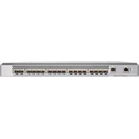
The switch has 8 auto-sensing 10/100/1000Base-T IEEE 802.3ab auto MDI/MDI-X RJ-45 ports. With this switch you can directly connect computers, printers, and servers to provide dedicated bandwidth to those devices, and you can build a switched network infrastructure by connecting it to hubs, other switches, or routers. In addition, the switch offers network management capabilities.
LEDs
The front panel of the switch provides status LEDs for system monitoring. The following table details the functions of the various indicators.
| System LED State Meaning | |
| Power(green) | On The switch is receiving power.Off The switch is NOT receiving power. |
| Fault(orange) | On The switch has a hardware failure, or has failed its self test. See chapter 4, “Troubleshooting” for more information.Off The normal state; indicates that there are no fault conditions on the switch. |
| Port LED State Meaning | ||
| Link/Act(green – overlaid with the port number) | On The port is enabled and receiving a link indication from the connected device.Off The port has no active network cable connected, or is not receiving link signal.Flashing Indicates that there is network activity on the port. | |
| FDx(green) | On Indicates the port is operating at full duplexOff Indicates the port is operating at half duplex | |
| Spd(green) | On Indicates the port is operating at 1000 Mbps.Off Indicates the port is operating at 10 or 100 Mbps. | |
Switch Features
The features of the ProCurve Switch 1800-8G include:
■ 8 auto-sensing 10/100/1000Base-T RJ-45 ports. ■ plug-and-play networking—all ports are enabled—just connect the network cables to active network devices and your switched network is operational. ■ IEEE 802.3ab Auto MDI/MDI-X on all twisted-pair ports, meaning that all connections can be made using straight-through twisted-pair cables. Cross-over cables are not required, although they will also work. The pin operation of each port is automatically adjusted for the attached device: if the switch detects that a 10/100 Mbps switch or hub is connected to the port, it configures the port as MDI; if the switch detects that a 10/100 Mbps end-node device is connected to the port, it configures the port as MDI-X. ■ automatic learning of the network addresses in each switch's 8000-address forwarding table. ■ automatically negotiated full-duplex operation for all 10/100/1000Base-T RJ-45 ports when connected to other auto-negotiating devices ■ easy management of the switch through several available interfaces:
- Web browser interface — an easy to use built-in graphical interface that can be accessed from common Web browsers.
- ProCurve Manager (PCM) — allows network administrators to discover and map the ProCurve Switch 1800 within their network and launch the ProCurve Switch 1800's built-in graphical interface from within PCM to configure the switch.
■ support for up to 64 IEEE 802.1Q-compliant VLANs so you can divide the attached end nodes into logical groupings that fit your business needs.
Switch Overview
Switch Hardware Features
■ support for up to 4 trunks so you can assign physical links to one logical link (trunk) that functions as a single, higher-speed link providing dramatically increased bandwidth. ■ support for many advanced features to enhance network performance—for a description, see the Management and Configuration Guide. ■ download of new switch software for product bug fixes.
Installing the Switch
The ProCurve Switch 1800-8G is easy to install. It comes with rubber feet that can be attached so the switch can be securely located on a horizontal surface. This chapter shows how to install the switch.
Included Parts
The following components ship with a ProCurve Switch 1800-8G:
■ ProCurve Switch 1800-8G Installation and Getting Started Guide (5991-4725), this manual ■ Customer Support/Warranty booklet ■ Four rubber feet ■ AC power adapter, one of the following:
12 V / 1 A adapter (40 degree C)
| Argentina | 5188-5679 |
| Australia/New Zealand | 5188-5678 |
| China | 5188-5677 |
| Continental Europe/Denmark | 5188-5673 |
| Japan | 5188-5676 |
| Korea | 5188-5675 |
| United Kingdom/Hong Kong | 5188-5672 |
| United States/Canada/Mexico | 5188-5671 |
13 V / 0.8 A adapter (55 degree C)
| Argentina | 5188-5699 |
| Australia/New Zealand | 5188-5698 |
| China | 5188-5697 |
| Continental Europe/Denmark | 5188-5693 |
| Japan | 5188-5696 |
| Korea | 5188-5695 |
| United Kingdom/Hong Kong | 5188-5692 |
| United States/Canada/Mexico | 5188-5691 |
Installation Procedures
Summary
Follow these easy steps to install your switch. The rest of this chapter provides details on these steps.
- Prepare the installation site. Make sure of the following:
- the network cabling is the correct type and length. See page 2-5. See page 2-4 for installation precautions.
- Verify the switch passes self test. This is a simple process of plugging the switch into a power source and observing that the LEDs on the switch's front panel show correct operation. See page 2-7.
- Mount the switch. The switch can be mounted on any horizontal surface.
- Connect power to the switch. Once the switch is mounted, plug in the AC power adapter. See page 2-8.
- Connect the network devices. Using the appropriate network cables, connect computers, servers, printers and other peripherals, and other network devices including other switches, hubs, or routers to the switch ports. See page 2-9.
At this point, the switch is fully installed and your network should be up and running. See the rest of this chapter if you need more detailed information on any of these installation steps.
Installation Precautions:
Follow these precautions when installing your switch.
Cautions
■ Make sure you use the power adapter supplied with the switch to connect it to an AC power source. ■ When installing the switch, since the unit does not have an On/Off power switch, an AC power outlet must be located near the switch and should be easily accessible in case the switch needs to be powered off. ■ Make sure the switch does not overload the power circuits, wiring, and over-current protection. To determine the possibility of overloading the supply circuits, add together the amperage ratings of all devices installed on the same circuit as the switch and compare the total with the rating limit for the circuit. The maximum amperage ratings are usually printed on the devices near the AC power connectors or power adapter connectors. ■ Do not install the switch in an environment where the operating ambient temperature might exceed 40 °C (104 °F). ■ Make sure the air flow around the sides of the switch is not restricted.
1. Prepare the Installation Site
■ Cabling Infrastructure - To ensure proper operation when installing the switch into a network, make sure that the current cables are suitable for 10Base-T, 100Base-TX, or 1000Base-T operation.
Be sure to follow the guidelines below to ensure proper operation when installing the switch into a network:
- Cable type: Unshielded twisted pair (UTP) or shielded twisted pair (STP) cables with RJ-45 connectors, maximum length 100 meters (328 ft); Category 3 or better for 10Base-T, Category 5 or better for 100Base-TX, and Category 5, 5e, or 6 for 1000Base-T.
- Protection from radio frequency interference emissions.
- Use electrical surge suppression.
- Use safe connections with no damaged cables, connectors or shields.
■ Installation Location - Before installing the switch, plan its location and orientation relative to other devices and equipment. At the front of the switch, leave at least 7.6 cm (3 inches) of space for the twisted-pair cabling. At the back of the switch, leave at least 2.6 cm (1 inch) of space for the adapter's power cord.
Installing the Switch
Installation Procedures
2. Verify the Switch Passes Self Test
Before mounting the switch in its network location, you should first check that it is working properly by plugging it into a power source and verifying that it passes its self test.
- Connect the adapter's power cord to the power connector on the back of the switch, and then plug the AC power adapter into a nearby properly grounded electrical outlet.

Note The switch does not have a power switch. It is powered on when the AC power adapter is connected to the switch and to a power source.
Caution Use only the AC power adapter supplied with the switch. Use of other adapters, including those that came with other ProCurve Networking products, may result in damage to the equipment.
- Check the LEDs on the switch. The LED behavior is described below.

When the switch is powered on, it performs its diagnostic self test. The self test takes approximately 8 seconds to complete.
Self Test LED Behavior:
During the self test:
- The LEDs will go on for a couple of seconds during the phases of the self test.
When the self test completes successfully:
• The Power LED stays on.
• The Fault LED stays off.
- In the default state, the FDx LED stays on and the Spd LED stays off.
- The port LEDs on the front of the switch go into their normal operational mode.
- If the ports are connected to active network devices the Link LEDs should be on.
If the LED display is different than what is described above, the self test has not completed correctly. Refer to chapter 4, "Troubleshooting" for diagnostic help.
3. Mount the Switch
After you have verified that the switch passes its self test, you are ready to mount the switch in a stable location. The switch can be mounted on a horizontal surface.
Horizontal Surface Mounting
Place the switch on a table or other horizontal surface. The switch comes with rubber feet in the accessory kit that can be used to help keep the switch from sliding on the surface.
Attach the rubber feet to the four corners on the bottom of the switch within the embossed angled lines. Use a sturdy surface in an uncluttered area. You may want to secure the networking cables and switch power cord to the table leg or other part of the surface structure to help prevent tripping over the cords.
Note
Make sure the air flow is not restricted around the sides of the switch.
4. Connect the Switch to a Power Source
- Plug the included AC power adapter into the switch's power connector and into a nearby AC power source.
- Re-check the LEDs during self test. See “Self Test LED Behavior:” on page 2-7.
5. Connect the Network Cables
Using the RJ-45 Connectors (10/100/1000Base-T ports)
To connect:
Push the RJ-45 plug into the RJ-45 jack until the tab on the plug clicks into place. When power is on for the switch and for the connected device, the Link/Act LED for the port should light to confirm a powered-on device (for example, an end node) is at the other end of the cable.
If the Link LED does not go on when the network cable is connected to the port, see "Diagnosing With the LEDs" in chapter 4, "Troubleshooting".

100-ohm unshielded or shielded twisted-pair cable:
• Category 3, 4, or 5 for 10 Mbps ports - Category 5 only for 100 Mbps ports - Category 5, 5e, or 6 for 1000 Mbps ports
Maximum distance: 100 meters
To disconnect:
Press the small tab on the plug and pull the plug out of the jack.
Installing the Switch
Installation Procedures
Configuring the Switch
Initial Configuration
The ProCurve Switch 1800-8G can be managed through a Web-browser interface that you can access from any PC or workstation in the connected network. For initial configuration, you may want to assign an IP address to the switch that is compatible with your existing network. However, you first need to access the Web interface using the switch's default IP address.
The following procedure shows how to access the Web interface and change the switch's IP address:
- Place the switch close to the PC that you will use for configuration. It helps if you can see the front panel of the switch while working on your PC.
- Connect the Ethernet port of your PC to any port on the front panel of your switch, start your PC (if it is not already running), connect power to the switch and when your PC has finished its start-up sequence, verify that you have a link by checking the LEDs on the front-panel of the switch (see “LEDs” on page 1-2 for more information).
- Set your PC's IP address to be on the same subnet as the switch. The default IP address of the switch is 192.168.2.10 and the subnet mask is 255.255.255.0, so the PC and switch are on the same subnet when they both have addresses that start 192.168.2.x. If the PC and switch are already on the same subnet, proceed directly to step 4. Otherwise, you must manually set the PC's IP
address to 192.168.2.x (where "x" can be any number from 1 to 255, except 10). If you are unfamiliar with this process, see "Changing PC's IP Address" on page 3-2.
- Open your Web browser and enter the address http://192.168.2.10. If your PC is properly configured, you will see the login page of your switch. If you do not see the login page, check your settings and repeat step 3.
- There is no default password, just click the Login button to access the Web management interface.
- From the menu, click SYSTEM, then IP Address. On the IP Address page, enter the IP address, Subnet Mask and Gateway IP Address for the switch, then click on the APPLY button.
No other configuration changes are required at this stage, but it is recommended that you configure an administrator password before logging out. From the menu, click SYSTEM, then Password. On the Password page, fill in all the fields before clicking on the APPLY button.
Note If you cannot remember the switch's IP address or password, you can restore the factory default settings by following the procedure described in the "Troubleshooting" section.
Changing PC's IP Address
To change the IP address of your PC:
- On Windows XP, go to Start, Settings, Network and Dial-up Connections.
- Right-click the connection icon of which the IP address you want to change, and then click Properties.
- In the General tab, under Components checked are used by this connection, click to select Internet Protocol (TCP/IP), and then click Properties to open the Internet Protocol (TCP/IP) Properties dialog box.
- In the Internet Protocol (TCP/IP) Properties dialog box, click to select Use the following IP address.
- In IP address, Subnet mask, and Default gateway, type your intended information.
- Click OK to save the changes and quit.
Where to Go From Here
For more information on the Web browser interface and all the features that can be configured on the ProCurve 1800-8G switch, see the ProCurve Series 1800 Switch Management and Configuration Guide, which is available on the ProCurve Networking Web site, http://www.procurve.com.
Troubleshooting
This section describes how to troubleshoot the switch. For more information, see the chapter “Troubleshooting” in the ProCurve Series 1800 Switch Management and Configuration Guide, which is available on the ProCurve Networking Web site, http://www.procurve.com.
This chapter describes the following:
■ basic troubleshooting tips (page 4-1) ■ diagnosing with the LEDs (page 4-2) ■ hardware diagnostic tests (page 4-4) ■ ProCurve Networking Customer Support Services (page 4-5)
Basic Troubleshooting Tips
Common problems and their solutions are listed in the following table.
For more information on possible network problems and their solutions, refer to the technical note “Troubleshooting LAN Performance and Intermittent Connectivity Problems”, which can be found on the ProCurve Networking Web site, http://www.procurve.com, in the Information Library section.
| Problem Resolution | |
| Switch fails Power On Self Test (POST) | Troubleshoot using the LEDs. See “Diagnosing With the LEDs” on page 4-2 |
| Link light does not light when a cable is connected. | Look for loose or obviously faulty connections. If they appear to be OK, make sure the connections are snug. If that does not correct the problem, try a different cable. |
Diagnosing With the LEDs
LED patterns on the switch may indicate a problem condition.
- Check in the table for the LED pattern that you see on your switch.
- Refer to the corresponding diagnostic tip on the next few pages.
| LED Pattern Indicating Problems | Diagnostic Tips | ||
| Power Fault Port Link | |||
| Off with power adapter plugged in | * | * | 1 |
| On Prolonged On * | 2 | ||
| On Off Off with cable | connected | 3 | |
| * This LED is not important for the diagnosis. | |||
Diagnostic Tips:
| Ti Problem Solution | ||
| 1 | The switch's power adapter is not plugged into an active AC power source, or the power adapter may have failed. | 1. Verify the AC power adapter is plugged into an active power source and to the switch. Make sure these connections are snug.2. Try power cycling the switch by unplugging and plugging in the power.3. If the Power LED is still not on, verify that the AC power source works by plugging another device into the outlet. Or try plugging the switch into a different outlet.If this condition persists, the switch's power adapter may have failed. Call your ProCurve Networking authorized network reseller, or use the electronic support services from ProCurve Networking to get assistance. See the Customer Support/Warranty booklet for more information. |
| 2 | A switch hardware failure was detected during self test. | Try power cycling the switch. If the fault indication reoccurs, the switch may have failed. Call your ProCurve Networking authorized network reseller, or use the electronic support services from ProCurve Networking to get assistance. See the Customer Support/Warranty card for more information. |
| 3 | The network connection is not working properly. | Try the following procedures:For the indicated port, verify that both ends of the cabling, at the switch and the connected device, are secure.Verify the connected device and switch are both powered on and operating correctly.Verify the connected devices comply with the appropriate IEEE 802.3 standard, including transmission of the Link signal.If the other procedures don't resolve the problem, try using a different port or a different cable. |
Troubleshooting
Forgotten the IP Address or Password
Forgotten the IP Address or Password
If you have forgotten the switch's IP address or administration password you can return the switch to its factory default state by doing the following:
- Remove the power adapter from the back of the switch.
- Connect port 1 to port 2 on the front panel using a standard network cable.
- Reconnect the power adapter to the rear of the switch.
- Wait at least 40 seconds before disconnecting port 1 from port 2.
After completing this procedure, there will be no password, the IP address will be returned to the default 192.168.2.10, and all configuration settings will be returned to factory defaults.
Hardware Diagnostic Tests
Testing the Switch by Resetting It
If you believe that the switch is not operating correctly, you can reset the switch to test its circuitry. To reset the switch, unplug and plug in the adapter's power adapter (power cycling).
Power cycling causes the switch to perform its power-on self-test, and almost always will resolve any temporary operational problems.
ProCurve Networking Customer Support Services
If you are still having trouble with your switch, ProCurve Networking offers support 24 hours a day, seven days a week through the use of a number of automated electronic services. See the Customer Support/Warranty booklet that came with your switch for information on how to use these services to get technical support. The ProCurve Networking Web site, http://www.procurve.com also provides up-to-date support information.
Additionally, your ProCurve Networking authorized network reseller can provide you with assistance, both with services that they offer and with services offered by ProCurve Networking.
Before Calling Support
Before calling your networking dealer or ProCurve Networking Support, to make the support process most efficient, you first should have retrieved the following information:
Information Item Information Location
- product identification the front of the switch
- details about the switch's status including the software (OS) version, a copy of the switch configuration, a copy of the switch Event Log, and a copy of the switch status and counters information
- copy of your network topology map, including network addresses assigned to the relevant devices
Web interface
your network records
Specifications
Physical
Width: 19.6 cm (7.7 in)
Depth: 11.6 cm (4.5 in)
Height: 4.4 cm (1.73 in)
Weight: 0.54 kg (1.19 lbs)
Electrical
DC voltage: 12-13 volts
Maximum current: 1.0-0.8 A
Environmental
Operating Non-Operating
Temperature: 0 °C to 40 °C (32 °F to 104 °F) -40 °C to 70 °C (-40 °F to 158 °F)
Relative humidity: 10 % to 90 % at 40 °C (104 °F) 10 % to 90 % at 65 °C (149 °F) (non-condensing)
Maximum altitude: 2 km (6,562 ft) 2 km (6,562 ft)
Specifications
Connectors
The 10/100/1000 Mbps RJ-45 twisted-pair ports are compatible with the following standards:
- IEEE 802.3ab 1000Base-T
- IEEE 802.3u 100Base-TX
- IEEE 802.3 10Base-T
Safety
The switch complies with these safety standards:
EN60950-1 / IEC 60950-1, CSA 22.2 No. 60950-1, UL 60950-1
Safety and EMC Regulatory Statements
Safety Information

WARNING
CAUTION
Documentation reference symbol. If the product is marked with this symbol, refer to the product documentation to get more information about the product.
A WARNING in the manual denotes a hazard that can cause injury or death.
A CAUTION in the manual denotes a hazard that can damage equipment.
Do not proceed beyond a WARNING or CAUTION notice until you have understood the hazardous conditions and have taken appropriate steps.
Grounding
These are safety class I products and have protective earthing terminals. There must be an uninterruptible safety earth ground from the main power source to the product's input wiring terminals, power cord, or supplied power cord set. Whenever it is likely that the protection has been impaired, disconnect the power cord until the ground has been restored.
Safety and EMC Regulatory Statements
Safety Information
For LAN cable grounding:
■ If your LAN covers an area served by more than one power distribution system, be sure their safety grounds are securely interconnected. ■ LAN cables may occasionally be subject to hazardous transient voltages (such as lightning or disturbances in the electrical utilities power grid). Handle exposed metal components of the network with caution.
Servicing
There are no user-serviceable parts inside these products. Any servicing, adjustment, maintenance, or repair must be performed only by service-trained personnel.
These products do not have a power switch; they are powered on when the adapter's power cord is plugged in.
Safety and EMC Regulatory Statements
Safety Information
Safety and EMC Regulatory Statements
Safety Information
Safety and EMC Regulatory Statements
Safety Information
Safety and EMC Regulatory Statements
Safety Information
Safety Information (Japan)
Safety Considerations
Safety Symbols

EMC Regulatory Statements
U.S.A.
FCC Class A
This equipment has been tested and found to comply with the limits for a Class A digital device, pursuant to part 15 of the FCC Rules. These limits are designed to provide reasonable protection against harmful interference when the equipment is operated in a commercial environment. This equipment generates, uses, and can radiate radio frequency energy and, if not installed and used in accordance with the instruction manual, may cause harmful interference to radio communications. Operation of this equipment in a residential area is likely to cause harmful interference in which case the user will be required to correct the interference at his own expense.
You are cautioned that changes or modifications not expressly approved by the party responsible for compliance could void your authority to operate the equipment.
Canada
This product complies with Class A Canadian EMC requirements.
Australia/New Zealand

This product complies with Australia/New Zealand EMC Class A requirements.
Japan
VCCI Class A
DECLARATION OF CONFORMITY
according to ISO/IEC Guide 22 and EN45014
Manufacturer's Name: Hewlett-Packard Company
Manufacturer's Address: 8000 Foothills Blvd
Roseville,
CA 95747-5502
U.S.A.
declares that the product:
Product Name: ProCurve Switch 1800-8G
ProCurve Switch 1800-24G
Model Number: J9029A and J9028A
Accessories:
Regulatory Model Number: RSVLC-0510
conforms to the following Product Specifications:
Safety: EN 60950:2001
IEC
60950:2001
EMC: EN 55022:1998 +A1:200 +A2:2003 / CISPR-22:1997 Class A +A1:2000 +A2:2002
EN 55024:1998)+A1:2001+A2:2003
EN 61000-3-2:2000 - Harmonics
EN 61000-3-3:1995 +A1:2001 +A2:2003 - Flicker
Supplementary Information:
The product herewith complies with the requirements of the Low Voltage Directive 73/23/EEC and the EMC Directive 89/336/EEC and carries the CE marking accordingly.
Tested with Hewlett-Packard Co. products only.
Roseville, 05-May-2006

Mike Avery,
Regulatory Engineering Manager
European Contact: Your local Hewlett-Packard Sales and Service Office or Hewlett-Packard GmbH, Department TRE, Herrenberger Strasse 140, D-71034 Böblingen (FAX: +49-7031-14-3143).
Recycle Statements
Waste Electrical and Electronic Equipment (WEEE) Statements

Disposal of Waste Equipment by Users in Private Household in the European Union
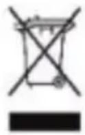
This symbol on the product or on its packaging indicates that this product must not be disposed of with your other household waste. Instead, it is your responsibility to dispose of your waste equipment by handing it over to a designated collection point for the recycling of waste electrical and electronic equipment. The separate collection and recycling of your waste equipment at the time of disposal will help to conserve natural resources and ensure that it is recycled in a manner that protects human health and the environment. For more information about where you can drop off your waste equipment for recycling, please contact your local city office, your household waste disposal service or the shop where you purchased the product.
connecting cables to switch ports ... 2-9
connecting the switch to a power source ... 2-8
connector specifications ... A-2
D
description
LEDs ... 1-2
diagnostic tests ... 4-4
testing the switch only ... 4-4-4-5
E
electrical specifications, switch ... A-1
EMC regulatory statements ... B-1 3
environmental specifications, switch ... A-1
F
FDx LEDs
description ... 1-2
H
horizontal surface, mounting switch on ... 2-8
I
included parts ... 2-1
installation
connecting the switch to a power source ... 2-8
on a horizontal surface ... 2-8
precautions ... 2-4
summary ... 2-3
L
LEDs
behavior during self test ... 2-7
descriptions of ... 1 - 2
error indications ... 4-2, 4-4
FDx
description ... 1-2
Link/Act ... 1 - 2
Power ... 1 - 2
behavior during self test ... 2 - 7
Link/Act LEDs ... 1 - 2
M
mounting the switch
on a horizontal surface ... 2-8
N
network devices
connecting to the switch ... 2-9
network ports
connecting to ... 2-9
standards compliance ... A - 2
P
parts, included with the switch ... 2 - 1
physical specifications, switch ... A - 1
port LEDs
FDx ... 1-2
Link/Act ... 1 - 2
ports
10/100Base-TX, location on switch ... 1-1
network connections ... 2 - 9
Power LED ... 1 - 2
behavior during self test ... 2-7
power source
connecting the switch to ... 2-8
precautions
mounting the switch ... 2-4
power requirements ... 2-4
R
rack
mounting precautions ... 2-4
regulatory statements ... B-13
resetting the switch
troubleshooting procedure ... 4-4 - 4-5
S
safety specifications ... A-2
self test
LED behavior during ... 2-7
specifications
connectors ... A-2
electrical ... A - 1
environmental ... A - 1
physical ... A - 1
safety ... A - 2
summary of switch installation ... 2 - 3
switch
connecting to a power source ... 2-8
electrical specifications ... A - 1
environmental specifications ... A-1
included parts ... 2 - 1
mounting on horizontal surface ... 2-8
physical specifications ... A - 1
switch operation
verifying after installation ... 2-6
T
testing
diagnostic tests ... 4-4
switch operation ... 4-4-4-5
tips for troubleshooting ... 3-3, 4-1
troubleshooting
basic tips ... 3-3, 4-1
common network problems ... 3-3, 4-1
diagnostic tests ... 4-4
testing the switch ... 4-4-4-5
Technical information in this document is subject to change without notice.
© Copyright 2006
Hewlett-Packard Development Company, L.P. Reproduction, adaptation, or translation without prior written permission is prohibited except as allowed under the copyright laws.
Printed in Taiwan
October 2006
Manual Part Number
5991-4725


- PROCURVE SWITCH 1800-8G
- © COPYRIGHT 2006 HEWLETT-PACKARD DEVELOPMENT COMPANY L.P
- PUBLICATION NUMBER
- APPLICABLE PRODUCT
- SAFETY
- DISCLAIMER
- WARRANTY
- SWITCH OVERVIEW
- INSTALLING THE SWITCH
- CONFIGURING THE SWITCH
- TROUBLESHOOTING
- A SPECIFICATIONS
- B SAFETY AND EMC REGULATORY STATEMENTS
- C RECYCLE STATEMENTS
- SWITCH HARDWARE FEATURES
- SWITCH PORTS
- LEDS
- SWITCH FEATURES
- INCLUDED PARTS
- INSTALLATION PROCEDURES
- SUMMARY
- INSTALLATION PRECAUTIONS
- CAUTIONS
- PREPARE THE INSTALLATION SITE
- VERIFY THE SWITCH PASSES SELF TEST
- SELF TEST LED BEHAVIOR
- DURING THE SELF TEST
- WHEN THE SELF TEST COMPLETES SUCCESSFULLY
- MOUNT THE SWITCH
- HORIZONTAL SURFACE MOUNTING
- NOTE
- CONNECT THE SWITCH TO A POWER SOURCE
- CONNECT THE NETWORK CABLES
- USING THE RJ-45 CONNECTORS (10/100/1000BASE-T PORTS)
- TO CONNECT
- TO DISCONNECT
- INITIAL CONFIGURATION
- CHANGING PC'S IP ADDRESS
- WHERE TO GO FROM HERE
- BASIC TROUBLESHOOTING TIPS
- DIAGNOSING WITH THE LEDS
- FORGOTTEN THE IP ADDRESS OR PASSWORD
- HARDWARE DIAGNOSTIC TESTS
- TESTING THE SWITCH BY RESETTING IT
- PROCURVE NETWORKING CUSTOMER SUPPORT SERVICES
- BEFORE CALLING SUPPORT
- INFORMATION ITEM INFORMATION LOCATION
- SPECIFICATIONS
- PHYSICAL
- ELECTRICAL
- ENVIRONMENTAL
- OPERATING NON-OPERATING
- CONNECTORS
- SAFETY AND EMC REGULATORY STATEMENTS
- SAFETY INFORMATION
- GROUNDING
- SERVICING
- SAFETY INFORMATION (JAPAN)
- EMC REGULATORY STATEMENTS
- CANADA
- AUSTRALIA/NEW ZEALAND
- JAPAN
- DECLARATION OF CONFORMITY
- RECYCLE STATEMENTS
- WASTE ELECTRICAL AND ELECTRONIC EQUIPMENT (WEEE) STATEMENTS
- DISPOSAL OF WASTE EQUIPMENT BY USERS IN PRIVATE HOUSEHOLD IN THE EUROPEAN UNION
- D
- E
- F
- H
- I
- L
- M
- N
- P
- R
- S
- T
Brand : HP
Model : ProCurve 1800-8G
Category : Router