
K 342 W - Cooker INDESIT - Free user manual and instructions
Find the device manual for free K 342 W INDESIT in PDF.


| Product Type | Freestanding Cooker |
| Brand | Indesit |
| Model | K 342 W |
| Width (cm) | 60 |
| Depth (cm) | 60 |
| Height (cm) | 85-90 (adjustable) |
| Weight (kg) | Approx. 50 |
| Hob Type | Gas (4 burners) |
| Oven Type | Electric conventional |
| Oven Capacity (L) | Approx. 65 |
| Oven Functions | Bake, grill, fan-assisted |
| Power Supply | 230 V / 50 Hz (electric); LPG or natural gas (hob) |
| Energy Class | A |
| Cleaning | Enamel oven cavity; removable door for easy cleaning |
| Safety Features | Flame failure device on gas burners; oven door lock |
| Control Type | Knobs |
| Color | White |
| Spare Parts Availability | Standard parts available; use authorized service centers |
| Repairability Index | 7/10 |
| Included Accessories | Grill rack, baking tray |
| Installation | Freestanding; gas connection required |
Frequently Asked Questions - K 342 W INDESIT
User questions about K 342 W INDESIT
0 question about this device. Answer the ones you know or ask your own.
Ask a new question about this device
Download the instructions for your Cooker in PDF format for free! Find your manual K 342 W - INDESIT and take your electronic device back in hand. On this page are published all the documents necessary for the use of your device. K 342 W by INDESIT.
USER MANUAL K 342 W INDESIT
Installation and use
GB Cooker with gas oven and gas grill
Instructions for installation and use 15

Fig. C Fig. D
Fig. E


Fig. F Fig. G
* At 15°C and 1013 mbar - dry gas
** Propane P.C.S. = 50.37 MJ/kg
*** Butane P.C.S. = 49.47 MJ/kg
Natural P.C.S. = 37.78 MJ/m³

K 342 G/R K 342 GB/R K 342 GS/R K 343 GS/R


To maintain the EFFICIENCY and SAFETY of this appliance, we recommend:
- call only the Service Centers authorized by the manufacturer • always use original Spare Parts
1 This appliance is intended for non-professional use within the home. 2 These instructions are only for those countries whose symbols appear in the booklet and on the serial number plate of the appliance. 3 This owner's manual is for a class 1 appliance (insulated) or class 2, subclass 1 appliances (installed between two cabinets). 4 Before using your appliance, read the instructions in this owner's manual carefully since it provides all the information you need to ensure safe installation, use and maintenance. Always keep this owner's manual close to hand since you may need to refer to it in the future. 5 When you have removed the packing, check that the appliance is not damaged. If you have any doubts, do not use the appliance and contact your nearest Ariston Service Centre. Never leave the packing components (plastic bags, polystyrene foam, nails, etc.) within the reach of children since they are a source of potential danger. 6 The appliance must be installed only by a qualified technician in compliance with the instructions provided. The manufacturer declines all liability for improper installation, which may result in personal injury and damage to property. 7 The electrical safety of this appliance can only be guaranteed if it is correctly and efficiently earthed, in compliance with regulations on electrical safety. Always ensure that the earthing is efficient. If you have any doubts, contact a qualified technician to check the system. The manufacturer declines all liability for damage resulting from a system which has not been earthed. 8 Before plugging the appliance into the mains, check that the specifications indicated on the data plate (on the appliance and/or packaging) correspond with those of the electrical and gas systems in your home. 9 Check that the electrical capacity of the system and sockets will support the maximum power of the appliance, as indicated on the data plate. If you have any doubts, contact a qualified technician. 10 An omnipolar switch with a contact opening of at least 3 mm or more is required for installation. 11 If the socket and appliance plug are not compatible, have the socket replaced with a suitable model by a qualified technician, who should also check that the cross-section of the socket cable is sufficient for the power absorbed by the appliance. The use of adaptors, multiple sockets and/or extensions is not recommended. If their use cannot be avoided, remember to use only single or multiple adapters and extensions which comply with current safety regulations. In these cases, never exceed the maximum current capacity indicated on the individual adaptor or extension and the maximum power indicated on the multiple adapter. 12 Do not leave the appliance plugged in if it is not in use. Switch off the main switch and gas supply when you are not using the appliance. 13 The openings and slots used for ventilation and heat dispersion must never be covered.
14 The user must not replace the supply cable of this appliance. Always contact an after-sales service centre which has been authorised by the manufacturer if the cable has been damaged or needs replacement. 15 This appliance must be used for the purpose for which it was expressly designed. Any other use (e.g. heating rooms) is considered to be improper and consequently dangerous. The manufacturer declines all liability for damage resulting from improper and irresponsible use. 16 A number of fundamental rules must be followed when using electrical appliances. The following are of particular importance:
- Do not touch the appliance when your hands or feet are wet.
- Do not use the appliance barefooted.
- Do not use extensions, but if they are necessary, caution must be exercised.
- Never pull the power supply cable or the appliance to unplug the appliance plug from the mains.
- Never leave the appliance exposed to atmospheric agents (rain, sun etc.)
- Do not allow children or persons who are not familiar with the appliance to use it, without supervision.
17 Always unplug the appliance from the mains or switch off the main switch before cleaning or carrying out maintenance. 18 If you are no longer using an appliance of this type, remember to make it unserviceable by unplugging the appliance from the mains and cutting the supply cable. Also make all potentially dangerous parts of the appliance safe, above all for children who could play with the appliance. 19 To avoid accidental spillage do not use cookware with uneven or deformed bottoms on the burners. Turn the handles of pots and pans inwards to avoid knocking them over accidentally. 20 Some parts of the appliance remain heated for a long time after use. Make sure not to touch them. 21 Never use flammable liquids such as alcohol or gasoline, etc. near the appliance when it is in use. 22 When using small electric appliances near the hob, keep the supply cord away from the hot parts. 23 Make sure the knobs are in the “•”/” _” position when the appliance is not in use. 24 When the appliance is in use, the heating elements and some parts of the oven door become extremely hot. Make sure you don't touch them and keep children well away. 25 Gas appliances require regular air exchange to ensure trouble-free performance. When installing the cooker, follow the instructions provided in the paragraph on "Positioning" the appliance. 26 The glass top (only on certain models) can shatter if it is overheated. Therefore, all of the burners or hot plates must be turned off before the top is closed. 27 If the cooker is placed on a pedestal, take the necessary precautions to prevent the same from sliding off the pedestal itself.
Installation
All instruction on the following pages must be carried out by a competent person (corgi registered) in compliance with gas safety (installation and use) regulation 1984.
Important: disconnect the cooker from the electricity and gas supply when any adjustment, etc.
Positioning your appliance
Your cooker is designed with a degree of protection against overheating in class X; the appliance can therefore be installed next to cabinets, provided the height does not exceed that of the hob. The wall touching the back panel of the cooker should be non-inflammable. Remember that during use, the back panel of the cooker may reach a temperature up to 50°C above that of the room temperature.
Important: this appliance may be installed and used only in permanently ventilated rooms in compliance with current directives. The following precautions should be taken:
a) The room must be provided with an external exhaust system obtained with a hood or with an electric ventilator that goes on automatically each time the unit is switched on.


In the case of chimneys or flues directly to the exterior (for cookers) with branches
b) The room must be provided with a system for air inflow which is necessary for a regular combustion. The air flow necessary for the combustion should be at least 2 m³/h for kW of installed power. The system may be realized by drawing the air directly from outside the building through a pipe that has at least a 100 cm² useable section and which must not be accidentally obstructed (Fig. A). And further it may be realized indirectly from other adjacent rooms which are provided with a ventilation pipe for the expulsion of the fumes to the outside of the building as foresaid, and which must not be part of the building in common use or rooms with risk of fire, or bedrooms (Fig. B).
Detail A: Adjacent room to be ventilated

Fig. A Fig. B Examples of ventilation openings Increased opening between for the comburent air the door and and floor
c) During prolonged use of the appliance you may consider it necessary to open a window to the outside to improve ventilation.
d) The liquefied petroleum gases, which are heavier than air, stagnate towards the ground. Therefore, the rooms containing LPG cans must have openings towards the outside in order to allow the venting from the ground of eventual gas leak. Thus, the LPG cans must not be installed or settled in rooms that are below the ground level, (cellar, etc.) whether the cans are empty or partially full. It is advisable to keep in the room only the can which is being used, and it must be placed away from direct heat sources (ovens, fireplaces, stoves, etc.) that could make the can reach temperatures higher than 50°C.
Levelling your appliance (only on a few models)
Your cooker is supplied with feet for levelling the appliance. If necessary, these feet can be screwed into the housings in the corners of the cooker base.

Mounting the legs (only on a few models)
Press-fit legs are supplied which fit under the base of your cooker.

Installation of the cooker
The appliance can be installed next to furniture units which are no taller than the top of the cooker hob. The wall in direct contact with the back panel of the cooker must be made of non-flammable material. During operation the back panel of the cooker could reach a temperature of 50°C above room temperature. For proper installation of the cooker, the following precautions must be taken:
a) The appliance can be placed in a kitchen, dining room or bedsit, but not in a bathroom. b) All furniture around the appliance must be placed at least 200 mm from the top of the cooker, should the surface of the appliance be higher than the worktop of this furniture. Curtains should not be placed behind the cooker or less than 200 mm away from the sides of the appliance. c) Any hoods must be installed according to the requirements in the installation manual for the hoods themselves. d) If the cooker is installed beneath a wall cabinet, the
latter must be situated at a minimum of 420 mm above the hob. The minimum distance between the worktop and kitchen units made of combustible material is 700 mm.
e) The wall in direct contact with the back panel of the cooker must be made of non-flammable materials.

Connecting the gas
The appliance should be connected to the mains or to a gas cylinder in compliance with current directives. Before making the connection, check that the cooker is regulated for the gas supply you are using. If not, follow the instructions indicated in the paragraph "Adapting to different types of gas". On some models the gas supply can be connected on the left or on the right, as necessary; to change the connection, reverse the position of the hose holder with that of the cap and replace the gasket (supplied with the appliance). When using liquid gas from a cylinder, install a pressure regulator which complies with current directive.
Important: check that the supply pressure complies with the values indicated in table 1 “Characteristics of the burners and nozzles” since this will ensure safe operation, correct consumption and ensure a longer life to your appliance.
Connection with hose
Make the connection using a gas hose complying with the characteristics provided in current directive. The internal diameter of the pipe used is as follows:
- 8mm for liquid gas;
- 13mm for methane gas.
When installing the hose, remember to take the following precautions:
- No part of the hose should touch parts whose temperature exceeds 50°C; • The length of the hose should be less than 1500 mm;
- The hose should not be subject to twisting or pulling, and should not have bends or kinks.
- The hose should not touch objects with sharp edges, any moving parts, and it should not be crushed;
- The full length of the hose should be easy to inspect in order to check its condition;
Check that the hose fits firmly into place at the two ends and fix it with clamps complying with current directive. If any of the above recommendations cannot be adopted, flexible metal pipes should be used.
Should the cooker be installed according to the conditions of Class 2, subdivision 1, only a flexible metal pipe which is in compliance with current safety standards should be used to make the connection to the gas mains.
Connecting a flexible jointless stainless steel pipe to a threaded attachment
Remove the hose holder fitted on the appliance. The gas supply pipe fitting is a threaded 1/2 gas cylindrical male attachment. Only pipes and gaskets complying with current directives. The full length of the pipe must not exceed 2000 mm.
Tight control
Important: when installation has been completed, check the pipe fitting for leaks with a soapy solution. Never use a flame. Once the connection has been made, ensure that the flexible metal tube does not touch any moving parts and is not crushed.
Connecting the supply cable to the mains
Install a normalised plug corresponding to the load indicated on the data plate. When connecting the cable directly to the mains, install an omnipolar circuit-breaker with a minimum contact opening of 3 mm between the appliance and the mains. The omnipolar circuit breaker should be sized according to the load and should comply with current regulations (the earth wire should not be interrupted by the circuit breaker).
The supply cable should be positioned so that it does not reach a temperature of more than 50°C with respect to the room temperature, along its length. Before making the connection, check that:
- the limiter valve and the home system can support the appliance load (see data plate);
- the mains is properly earthed in compliance with current directives and regulations;
- there is easy access to the socket and omnipolar circuit breaker, once the hob has been installed.
N.B: never use reducers, adaptors or shunts since they can cause heating or burning.
Adapting the cooker to different types of gas
To adapt the cooker to a different type of gas than the one it was originally set up for (as indicated on the label attached to the lid), follow these steps:
a) Replace the hose holder mounted on the appliance with the one supplied in the "cooker accessories" bag. Important: the hose holder for liquid gas is marked 8, and the one for methane gas is marked 13. Always fit the sealing gasket. b) Replacing the burner nozzles on the hob: - Remove the grids and slide the burners out of their housings. - Unscrew the nozzles using a 7 mm socket spanner, and replace them with nozzles for the new type of gas (see table 1 "Burner and nozzle characteristics"). - Reassemble all components by repeating the steps in reverse order.

c) Minimum regulation of the hob burners:
• Turn the tap to minimum.
- Remove the knob and adjust the regulation screw, which is located in or next to the tap pin, until the flame is small but steady.
N.B.: In the case of liquid gas, the regulation screw must be screwed in all the way.
- Check that the flame does not go out when you turn the tap quickly from high to low.
d) Regulating the primary air of the burners:
The primary air of the burners requires no regulation.
Adapting the gas oven to different types of gas
a) Replacing the oven burner nozzle: - Remove the warming drawer. - Remove the sliding protection "A" (see Fig. C). - Remove the screw and then the oven burner "V" (see Fig. D). Remove the oven door to facilitate this operation. - Unscrew the oven burner nozzle using the special socket spanner for the nozzles (see Fig. E), or better still a 7 mm socket spanner, and replace it with a nozzle suited to the new type of gas (see table 1).


Fig. C Fig. D
Fig. E
b) Minimum regulation of the gas oven burner with thermostat (see fig.):
- Light the burner as described in the paragraph "the oven knob" of the instruction booklet.
- Turn the knob to Max for about 10 minutes and then turn the knob to the Min setting;
- Remove the knob;
- Regulate the screw positioned outside the thermostat pin until the flame is small but steady.
N.B.: In the case of liquid gas, the regulation screw must be screwed in to the bottom.


Check that the burner does not turn off when you turn the knob from Max to Min and when you open and close the oven door quickly.
Adapting the gas grill to different types of gas
Replacing the nozzle of the grill burner:
- Remove the screw and then slide out the grill burner "V" (see Fig. F);
- Unscrew the grill burner nozzle using the special socket spanner for the nozzles (see Fig. G) or better still a 7 mm socket spanner; replace the nozzle with a nozzle for the new type of gas (see table 1).


Fig. F Fig. G
Important: When mounting the grill burner check that there is a space of at least 4 mm between the security thermocouple (if installed) and the burner.
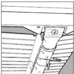
Pay particular attention to the plug wires and thermocouple tubes.
Important
On completion of the operation, replace the old rating sticker with one indicating the new type of gas used. This sticker is available from our Service Centres.
Note
Should the pressure of the gas used be different (or vary) from the recommended pressure, it is necessary to fit a suitable pressure regulator onto the inlet pipe in compliance with current National Regulations relative to "regulators for channelled gas".
Burner and nozzle characteristics
Table 1 Liquid Gas Natural Gas
| Burner Diameter (mm) | Thermal Power kW (p.c.s.*) | By-Pass 1/100 (mm) (mm) ** (mm) | Nozzle 1/100 (mm) | Flow* g/h | Nozzle 1/100 | Flow* l/h | Nozzle 1/100 | Flow* l/h | |||
| Nominal | Reduced | ||||||||||
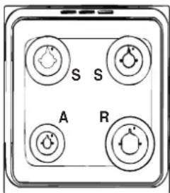
| Fast (Large)(R) | 100 | 3.00 | 0.7 | 41 | 86 | 218 | 214 | 116 | 286 | 143 | 286 |
| Semi Fast (Medium)(S) | 75 | 1.90 | 0.4 | 30 | 70 | 138 | 136 | 106 | 181 | 118 | 181 |
| Auxiliary (Small)(A) | 55 | 1.00 | 0.4 | 30 | 50 | 73 | 71 | 79 | 95 | 80 | 95 |
| Oven | - | 3.10 | 1.0 | 46 | 85 | 225 | 221 | 132 | 295 | 148 | 288 |
| Grill | - | 2.50 | - | - | 80 | 182 | 179 | 122 | 227 | 139 | 227 |
| Supply Pressures | Nominal (mbar) | 28-30 | 37 | 20 | 13 | ||||||
| Minimum (mbar) | 20 | 25 | 17 | 6,5 | |||||||
| Maximum (mbar) | 35 | 45 | 25 | 18 | |||||||
* At 15°C and 1013 mbar-dry gas ** Propane P.C.S. = 50,37 MJ/Kg *** Butane P.C.S. = 49,47 MJ/Kg Natural P.C.S. = 37,78 MJ/m³
| Table1 (For Hungary) | G 20 | G 25.1 | G 30 | ||||
| Burner | By-pass 1/100 (mm) | Thermal power kW | Nozzle 1/100 (mm) | Thermal power kW | Nozzle 1/100 (mm) | Thermal power kW | Nozzle 1/100 (mm) |
| Fast (R) | 41 | 3,30 | 116 | 2,60 | 116 | 2,60 | 86 |
| Semi Fast (S) | 30 | 2,10 | 106 | 1,70 | 106 | 1,70 | 70 |
| Auxiliary (A) | 30 | 1,15 | 79 | 0,90 | 79 | 0,90 | 50 |
| Oven | 46 | 3,50 | 132 | 2,60 | 132 | 3,00 | 85 |
| Grill | - | 2,60 | 122 | 2,00 | 122 | 2,40 | 80 |
| Supply pressures | 25 mbar | 25 mbar | 30 mbar | ||||
At 15°C and 1013 mbar-dry gas P.C.I. G20 37,780 MJ/m³ P.C.I. G30 122,8 MJ/m³ P.C.I. G25.1 32,510 MJ/m³
K 342 G/R
K 342 GB/R
K 342 GS/R
K 343 GS/R
Technical characteristics
Inner dimensions of the oven:
Width: 39 cm
Depth: 44 cm
Height: 34 cm
Inner Volume of the Oven:
58 It
Inner Dimensions of the Food Warmer:
Width: 42 cm
Depth: 44 cm
Height: 17 cm
Voltage and Frequency of Power Supply:
see data plate
Burners:
adaptable for use with all the types of gas indicated on the data plate situated inside the flap or, once the dishwarmer drawer has been opened, on the inside wall of the left-hand side panel.
CE
This appliance conforms with the following European Economic Community directives:
- 73/23/EEC of 19/02/73 (Low Voltage) and subsequent modifications;
- 89/336/EEC of 03/05/89 (Electromagnetic Compatibility) and subsequent modifications;
- 90/396/EEC of 29/06/90 (Gas) and subsequent modifications;
- 93/68/EEC of 22/07/93 and subsequent modifications.

The cooker with gas oven
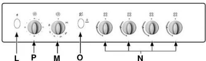
A Tray for Catching Overflows B Gas Burner C Flame Failure Device for Cooktop Burners (only a few models) D Top Grate E Control Panel F Adjustable Feet or Legs G Dripping Pan or Baking Sheet H Electronic Lighting Device (only a few models) K Oven Rack L Electronic Lighting for Hob Burners (only on certain models) M Oven and Grill Control Knob N Control Knobs for Gas Burners on Hob - Button for Oven and Rotisserie Light (only a few models) P Timer Knob (only a few models) Q Country Style Clock and Timer (only a few models)


The different functions and uses of the oven
The various functions included in the cooker are selected by operating the control devices located on the cooker control panel.
Control Knobs for the Gas Burners on the Hob (N)
The position of the gas burner controlled by each one of the knobs is shown by a symbol of a solid ring:•. To light one of the burners, hold a lighted match or lighter near the burner. Press down and turn the corresponding knob in the counter-clockwise direction to the maximum ⚙ setting. Each burner can be operated at its maximum, minimum or intermediate power. Shown on the knob are the different symbols for off • (the knob is on this setting when the symbol lines up with the reference mark on the control panel), for maximum ▶ and minimum ▶. To obtain these settings, turn the knob counter-clockwise with respect to the off position. To turn off the burner, turn the knob clockwise until it stops (corresponding again with the ● symbol).
Electronic Ignition for the Gas Hob
Some of the models are provided with instant electronic lighting of the hob gas burners; these models are identified by the presence of a lighting device (see detail H). This device operates when a slight pressure is applied to the "L" button marked with
* symbol. To light a specific burner just press the button labelled "L" while pushing the corresponding knob all the way in
and turning it counter-clockwise until it lights. For immediate lighting, first press the button and then turn the knob.
Some models are equipped with an ignition button incorporated into the control knob. If this is the case, the ignitor (H) is present, but not the "L" button (the symbol is located near each knob).
To light a burner, simply press the corresponding knob all the way in and then turn it anti-clockwise to the "High" setting, keeping it pressed in until the burner lights.
Important: Should the burner flames accidentally go out, turn off the control knob and wait at least 1 minute before trying to relight.
Models with Hob Gas Burner Safety Devices to Prevent
Leaks (only on certain models)
These models can be identified by the presence of the device itself (see detail C).
Important: Since the hob burners are equipped with a safety device, you must hold the control knob in for about 6 seconds after the burner has been lighted to allow the gas to pass until the safety thermocouple has heated.
Attention: before using the oven and grill for the first time, turn the oven on for approximately one half hour. Make sure that the oven is empty, the thermostat on high, the door open, and the room properly ventilated. The odor which can be detected at times is due to the evaporation off the substances used to protect the oven and the grill during the period between the time of production and installation of the appliance.
Attention: Only use the bottom shelf of the oven when using the rotisserie to cook (where present). For all other types of cooking, never use the bottom shelf and never place anything on the bottom of the oven when it is in operation because this could damage the enamel. Always place your cookware (dishes, aluminium foil, etc. etc.) on the grate provided with the appliance inserted especially along the oven guides.
Oven and Grill Control Knob (M)
This knob allows you to select the various features of the oven and to set the most appropriate cooking temperature from among those indicated on the knob itself (between Min and Max).
To light the oven burner, hold a lighted match or lighter near the "F" hole and, at the same time, press down and turn the oven knob counter-clockwise to the Max setting.

Since the cooker is equipped with a safety device which makes it necessary to keep the knob pressed in for about 6 seconds after the burner has been lighted to allow the gas to pass through freely.
The cooking temperature is selected by matching the desired temperature with the reference mark on the panel; the complete range of temperatures is shown below.
The temperature setting is then automatically reached and kept constant by the thermostat (which is controlled by the knob).
To use the grill, turn the knob clockwise till to setting after holding a lighted match or a lighter close to the grill burner. In the grill burner equipped with a safety device, the knob must be held pressed in for about 6 seconds in order to activate the flame failure device. In this way the infrared ray comes on for browning the food or cooking roast, chops, sausages, roast-beef, etc.; for grill cooking, place a drip-pan under the grill to catch the grease.

Important Notice: In the event the flame for the oven accidentally goes out, turn the control knob for the burner to the off position and do not relight the burner for at least one minute.
Important: when using the grill, the oven door must be left partly open by positioning the deflector "D" between door and panel to prevent the cooker knobs from overheating.

Attention
Avoid the children touch the oven door because it is very hot during the cooking.
Oven Light Button (O)
This button is marked by the symbol and switches on the light inside the oven so that you can monitor the cooking process without opening the door.
Cooking Control Timer Knob (only a few models)
Some models are equipped with a timer program to control when the oven shuts off during cooking. To use this feature, you must wind the "P" knob one full turn in the counter-clockwise direction
Then, turn the knob in the clockwise direction to set the time by matching up the indicator on the control panel with the number of minutes on the knob.
The rotisserie (only a few models)
To operate the rotisserie, proceed as follows:
a) place the dripping-pan on the 1st rack; b) insert the special rotisserie support on the 4th rack and position the spit by inserting it through the special hole into the rotisserie at the back of the oven; c) Activate the rotisserie by pressing the "O" button.

Storage recess below the oven (only a few models)
Below the oven a recess can be used to contain cooking pans and cooker accessories. Moreover, during oven operation, it may be used to keep food warm. To open the storage is necessary turn it downwards.
Caution: this storage recess must not be used to store inflammable materials.

Practical advice for burner use
In order to get the maximum yield it is important to remember the following:
- Use appropriate cookware for each burner (see table) so as to avoid flames overshooting the edges.
- At boiling point turn the knob to minimum.
- Use cookware with lids. • Always use cookware with flat bottoms.
| Burner ø Cookware diameter (cm) | |
| Fast (R) 24 - 26 | |
| Semi Fast (S) 16 - 20 | |
| Auxiliary (A) 10 - 14 | |
Country Style Clock and Timer

How to Set the Current Time
The oven must be connected to the power supply.
Pull and turn the knob in the clockwise direction to set the time.
N.B.: The clock is electric. Therefore, in the event of a power outage, the clock will stop for the entire time the oven remains without power. When the power comes back
on, the clock must be reset to the current time
Timer Feature
The timer operates by counting down a given period of time. This feature does not, however, turn the oven on or off. It merely emits an acoustical alarm when the time has run out.
How to Set the Timer
Turn the knob until the indicator is set on the length of time desired (using the inside numbers). The time is clearly visible through the transparent window on the indicator itself.
The timer will begin to count down immediately.
The sound will stop automatically after approximately 2 minutes and the timer will be set to the Symbol (clock function).
To turn off the buzzer, or to use only the clock, set the indicator on the symbol.
Cooking advice
The oven offers a wide range of alternatives that allow you to cook any type of food in the best possible way. With time, you will learn to make the best use of this versatile cooking appliance. The following directions are only a guideline, which may be varied according to your own personal experience.
Baking cakes
The oven should always be warm before putting in cakes. Wait until the end of preheating (about 10-15 minutes). Cake-
baking temperatures are normally around 160°C/200°C. Do not open the oven door during the baking process, as this could cause the cake to sink. In general:
| Pastry is too dry |
| Increase the temperature by 10°C and reduce the cooking time. |
Pastry dropped
Use less liquid or lower the temperature by 10°C.
Pastry is too dark on top
Place it on a lower rack, lower the temperature, and increase the cooking time.
Cooked well on the inside but sticky on the outside
Use less liquid, lower the temperature, and increase the cooking time.
The pastry sticks to the pan
Grease the pan well and sprinkle it with a dusting of flour or use greaseproof paper.
Cooking fish and meat
When cooking white meat, fowl, and fish, use low temperatures (150°C-175°C). When red meat must be superficially well-cooked but succulent inside, it is advisable to start with a high temperature (200-220°C) for a short time, and then reduce it later. Generally speaking, the more meat there is, the lower the temperature and the longer the cooking time should be. Place the meat in the center of the grid and put a spill tray underneath to catch grease drips. Insert the grid so that it is in the middle of the oven. If more heat from below is required, use the bottom shelf.
Cooker routine maintenance and cleaning
Before each operation, disconnect the cooker from the electricity. To assure the long life of the cooker, it must be thoroughly cleaned frequently, keeping in mind that:
- the enamelled parts and the self-cleaning panels are washed with warm water without using any abrasive powders or corrosive substances which could ruin them;
- the inside of the oven should be cleaned fairly often while it is still warm using warm water and detergent, followed by careful rinsing and drying;
- the flame spreaders should be washed frequently with hot water and detergent taking care to eliminate any scale;
- in cookers equipped with automatic lighting, the terminal part of the electronic instant lighting devices should be cleaned frequently and the gas outlet holes of the flame spreaders should be checked to make sure they are free of any obstructions;
- Stainless steel may become marked if it comes into contact with very hard water or harsh detergents (containing phosphorous) for long periods of time. After cleaning, it is advisable to rinse thoroughly and dry. It is also recommended to dry any water drops;
- On models with glass covers, the covers should be cleaned with hot water; the use of rough cloths or abrasives is to be avoided.
N.B: avoid closing the cover while the gas burners are still warm. Remove any liquid from the lid before opening it.
Important: periodically check the wear of the gas hose and substitute it if there are any defects; we recommended changing it every year.
Replacing the oven lamp
- Unplug the oven from the mains;
- Remove the glass cover of the lamp-holder;
- Remove the lamp and replace with a lamp resistant to high temperatures (300°C) with the following characteristics:
- Voltage 230V
- Wattage 25W
- Type E14

- Replace the glass cover and reconnect the oven to the mains.
Greasing the taps
The taps may jam in time or they may become difficult to turn. If so, they must be cleaned internally and the grease replaced.
N.B: This operation must be carried by a technician authorised by the manufacturer.
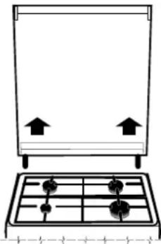
Removing the lid
The cooker lid can be removed to facilitate cleaning. To remove the lid, first open it completely and pull it upwards (see figure)
Practical advice for oven cooking
| Food to be cooked | Wt.(Kg) | Cooking position of shelves from bottom | Temperature(°C) | Pre-heating time(min) | Cooking time(min.) |
| Pasta | |||||
| Lasagne | 2.5 | 3 | 210 | 10 | 60-75 |
| Cannelloni | 2.5 | 3 | 200 | 10 | 40-50 |
| Pasta bakes au gratin | 2.5 | 3 | 200 | 10 | 40-50 |
| Meat | |||||
| Veal | 1.7 | 3 | 200 | 10 | 85-90 |
| Chicken | 1.5 | 3 | 220 | 10 | 90-100 |
| Duck | 1.8 | 3 | 200 | 10 | 100-110 |
| Rabbit | 2.0 | 3 | 200 | 10 | 70-80 |
| Pork | 2.1 | 3 | 200 | 10 | 70-80 |
| Lamb | 1.8 | 3 | 200 | 10 | 90-95 |
| Fish | |||||
| Mackerel | 1.1 | 3 | 180-200 | 10 | 35-40 |
| Dentex | 1.5 | 3 | 180-200 | 10 | 40-50 |
| Trout baked in paper | 1.0 | 3 | 180-200 | 10 | 40-45 |
| Pizza | |||||
| Napolitan | 1.0 3 220 15 15-20 | ||||
| Cake | |||||
| Biscuits | 0.5 | 3 | 180 | 15 | 30-35 |
| Tarts | 1.1 | 3 | 180 | 15 | 30-35 |
| Savoury pie | 1.0 | 3 | 180 | 15 | 45-50 |
| Raised Cakes | 1.0 | 3 | 165 | 15 | 35-40 |
| Grill cooking | |||||
| Veal steaks | 1 | 4 | 5 | 15-20 | |
| Cutlets | 1,5 | 4 | 5 | 20 | |
| Hamburgers | 1 | 3 | 5 | 7 | |
| Mackerels | 1 | 4 | 5 | 15-20 | |
| Toast sandwiches | n.° 4 | 4 | 5 | 5 | |
| Grill cooking with rotisserie | |||||
| Veal on the spit | 1 | - | 5 | 70-80 | |
| Chicken on the spit | 2 | - | 5 | 70-80 | |
| Grill cooking with multi-skewer rotisserie(only a few models) | |||||
| Meat kebabs | 1,0 | - | 5 | 40-45 | |
| Vegetable kebabs | 0,8 | - | 5 | 25-30 | |
NB: cooking times are approximate and may vary according to personal taste. When cooking using the grill, the dripping-pan must always be placed on the 1st oven rack from the bottom.
Installing the cooker

Fig C Fig D
Fig E


Fig F Fig G


Fig A Fig B
Installing the cooker
Fig. E


Fig. F, Fig. G


Baking sweets
Sweets that shrink
Use less liquid or lower the temperature by 10 °C
Lubricating the taps
Practical advice for oven cooking
| Alimentul de copt | Greutate (kg) | Pozitja pe raftul cuptorului (calculata de la partea inferioara) | Temperatura (°C) | Timpul de preincălzi re (min) | Timpul de coacere (min) |
| Paste | |||||
| Lasagna | 2'5 | 3 | 210 | 10 | 60-75 |
| Cannelloni | 2'5 | 3 | 200 | 10 | 40-50 |
| Paste gratinate | 2'5 | 3 | 200 | 10 | 40-50 |
| Carne | |||||
| Vitel | 1'7 | 3 | 200 | 10 | 85-90 |
| Pui | 1'5 | 3 | 220 | 10 | 90-100 |
| Rata | 1'8 | 3 | 200 | 10 | 100-110 |
| Iepure | 2'0 | 3 | 200 | 10 | 70-80 |
| porc | 2'1 | 3 | 200 | 10 | 70-80 |
| Miel | 1'8 | 3 | 200 | 10 | 90-95 |
| Peşte | |||||
| Scrumbie | 1'1 | 3 | 180-200 | 10 | 35-40 |
| Specie de peşte marin | 1'5 | 3 | 180-200 | 10 | 40-50 |
| Păstrăv | 1'0 | 3 | 180-200 | 10 | 40-45 |
| Pizza | |||||
| Naportana 1'0 3 220 15 15-20 | |||||
| Prăjituri | |||||
| Biscuți | 0'5 | 3 | 180 | 15 | 30-35 |
| Prăjitură cu marmeladă | 1'1 | 3 | 180 | 15 | 30-35 |
| Tură de salată | 1'0 | 3 | 180 | 15 | 45-50 |
| Turic crescute | 1'0 | 3 | 165 | 15 | 35-40 |
| Coacere cu grill | |||||
| Bistec de vițel | 1 | 4 | 5 | 15-20 | |
| Cotlet | 1'5 | 4 | 5 | 20 | |
| Hamburger | 1 | 3 | 5 | 7 | |
| Scrumbie | 1 | 4 | 5 | 15-20 | |
| Coacere grill cu rotisor | |||||
| Vitel fript | 1 | - | 5 | 70-80 | |
| Pui fript | 2 | - | 5 | 70-80 | |
| Coacere grill cu shashlik (doar anumite modele) | |||||
| Frigărui din carne | 1'0 | - | 5 | 40-45 | |
| Frigărui cu legume | 0'8 | - | 5 | 25-30 | |


Fig. C, Fig. D
Fig. E


Fig. F, Fig. G


Warning:
Baking table
- INSTALLATION
- POSITIONING YOUR APPLIANCE
- LEVELLING YOUR APPLIANCE (ONLY ON A FEW MODELS)
- MOUNTING THE LEGS (ONLY ON A FEW MODELS)
- INSTALLATION OF THE COOKER
- CONNECTING THE GAS
- CONNECTION WITH HOSE
- CONNECTING A FLEXIBLE JOINTLESS STAINLESS STEEL PIPE TO A THREADED ATTACHMENT
- TIGHT CONTROL
- CONNECTING THE SUPPLY CABLE TO THE MAINS
- ADAPTING THE COOKER TO DIFFERENT TYPES OF GAS
- ADAPTING THE GAS OVEN TO DIFFERENT TYPES OF GAS
- ADAPTING THE GAS GRILL TO DIFFERENT TYPES OF GAS
- IMPORTANT
- NOTE
- BURNER AND NOZZLE CHARACTERISTICS
- TECHNICAL CHARACTERISTICS
- BURNERS
- THIS APPLIANCE CONFORMS WITH THE FOLLOWING EUROPEAN ECONOMIC COMMUNITY DIRECTIVES
- THE COOKER WITH GAS OVEN
- THE DIFFERENT FUNCTIONS AND USES OF THE OVEN
- CONTROL KNOBS FOR THE GAS BURNERS ON THE HOB (N)
- ELECTRONIC IGNITION FOR THE GAS HOB
- MODELS WITH HOB GAS BURNER SAFETY DEVICES TO PREVENT
- OVEN AND GRILL CONTROL KNOB (M)
- ATTENTION
- OVEN LIGHT BUTTON (O)
- COOKING CONTROL TIMER KNOB (ONLY A FEW MODELS)
- THE ROTISSERIE (ONLY A FEW MODELS)
- PRACTICAL ADVICE FOR BURNER USE
- COUNTRY STYLE CLOCK AND TIMER
- HOW TO SET THE CURRENT TIME
- TIMER FEATURE
- HOW TO SET THE TIMER
- COOKING ADVICE
- BAKING CAKES
- PASTRY DROPPED
- PASTRY IS TOO DARK ON TOP
- COOKED WELL ON THE INSIDE BUT STICKY ON THE OUTSIDE
- THE PASTRY STICKS TO THE PAN
- COOKING FISH AND MEAT
- COOKER ROUTINE MAINTENANCE AND CLEANING
- REPLACING THE OVEN LAMP
- GREASING THE TAPS
- REMOVING THE LID
- INSTALLING THE COOKER
- FIG A FIG B
- BAKING SWEETS
- SWEETS THAT SHRINK
- LUBRICATING THE TAPS
- WARNING
- BAKING TABLE
Brand : INDESIT
Model : K 342 W
Category : Cooker