
GR-33 - Synthesizer ROLAND - Free user manual and instructions
Find the device manual for free GR-33 ROLAND in PDF.


User questions about GR-33 ROLAND
0 question about this device. Answer the ones you know or ask your own.
Ask a new question about this device
Download the instructions for your Synthesizer in PDF format for free! Find your manual GR-33 - ROLAND and take your electronic device back in hand. On this page are published all the documents necessary for the use of your device. GR-33 by ROLAND.
USER MANUAL GR-33 ROLAND
Thank you, and congratulations on your choice of the Roland GR-33 Guitar Synthesizer.
Before using this unit, carefully read the sections entitled:
- USING THE UNIT SAFELY (page 2-3)
- IMPORTANT NOTES (page 9)
These sections provide important information concerning the proper operation of the unit.
Additionally, in order to feel assured that you have gained a good grasp of every feature provided by your new unit, Owner's manual should be read in its entirety. The manual should be saved and kept on hand as a convenient reference.
Copyright © 2000 ROLAND CORPORATION
All rights reserved. No part of this publication may be reproduced in any form without the written permission of ROLAND CORPORATION.
INSTRUCTIONS FOR THE PREVENTION OF FIRE, ELECTRIC SHOCK, OR INJURY TO PERSONS
About WARNING and CAUTION Notices
| ▲WARNING | Used for instructions intended to alert the user to the risk of death or severe injury should the unit be used improperly. |
| ▲CAUTION | Used for instructions intended to alert the user to the risk of injury or material damage should the unit be used improperly. * Material damage refers to damage or other adverse effects caused with respect to the home and all its furnishings, as well to domestic animals or pets. |
About the Symbols
| △ | The △ symbol alerts the user to important instructions or warnings. The specific meaning of the symbol is determined by the design contained within the triangle. In the case of the symbol at left, it is used for general cautions, warnings, or alerts to danger. |
| ◎ | The ⊙ symbol alerts the user to items that must never be carried out (are forbidden). The specific thing that must not be done is indicated by the design contained within the circle. In the case of the symbol at left, it means that the unit must never be disassembled. |
| ◎ | The ● symbol alerts the user to things that must be carried out. The specific thing that must be done is indicated by the design contained within the circle. In the case of the symbol at left, it means that the power-cord plug must be unplugged from the outlet. |
ALWAYS OBSERVE THE FOLLOWING
WARNING
- Before using this unit, make sure to read the instructions below, and the Owner's Manual.

- Do not open (or modify in any way) the unit or its AC adaptor.

- Do not attempt to repair the unit, or replace parts within it (except when this manual provides specific instructions directing you to do so). Refer all servicing to your retailer, the nearest Roland Service Center, or an authorized Roland distributor, as listed on the "Information" page.

- Never use or store the unit in places that are:


- Subject to temperature extremes (e.g., direct sunlight in an enclosed vehicle, near a heating duct, on top of heat-generating equipment); or are
- Damp (e.g., baths, washrooms, on wet floors); or are
- Humid; or are
- Exposed to rain; or are
- Dusty; or are
-
Subject to high levels of vibration.
-
Make sure you always have the unit placed so it is level and sure to remain stable. Never place it on stands that could wobble, or on inclined surfaces.

- Be sure to use only the AC adaptor supplied with the unit. Also, make sure the line voltage at the installation matches the input voltage specified on the AC adaptor's body. Other AC adaptors may use a different polarity, or be designed for a different voltage, so their use could result in damage, malfunction, or electric shock.

WARNING
- Do not excessively twist or bend the power cord, nor place heavy objects on it. Doing so can damage the cord, producing severed elements and short circuits. Damaged cords are fire and shock hazards!

- This unit, either alone or in combination with an amplifier and headphones or speakers, may be capable of producing sound levels that could cause permanent hearing loss. Do not operate for a long period of time at a high volume level, or at a level that is uncomfortable. If you experience any hearing loss or ringing in the ears, you should immediately stop using the unit, and consult an audiologist.

- Do not allow any objects (e.g., flammable material, coins, pins); or liquids of any kind (water, soft drinks, etc.) to penetrate the unit.


- Immediately turn the power off, remove the AC adaptor from the outlet, and request servicing by your retailer, the nearest Roland Service Center, or an authorized Roland distributor, as listed on the "Information" page when:

- The AC adaptor, the power-supply cord, or the plug has been damaged; or
- Objects have fallen into, or liquid has been spilled onto the unit; or
- The unit has been exposed to rain (or otherwise has become wet); or
- The unit does not appear to operate normally or exhibits a marked change in performance.
WARNING
- In households with small children, an adult should provide supervision until the child is capable of following all the rules essential for the safe operation of the unit.

- Protect the unit from strong impact. (Do not drop it!)

- Do not force the unit's power-supply cord to share an outlet with an unreasonable number of other devices. Be especially careful when using extension cords—the total power used by all devices you have connected to the extension cord's outlet must never exceed the power rating (watts/amperes) for the extension cord. Excessive loads can cause the insulation on the cord to heat up and eventually melt through.

- Before using the unit in a foreign country, consult with your retailer, the nearest Roland Service Center, or an authorized Roland distributor, as listed on the "Information" page.

CAUTION
- The unit and the AC adaptor should be located so their location or position does not interfere with their proper ventilation.

Always grasp only the plug on the AC adaptor cord when plugging into, or unplugging from, an outlet or this unit.

- Whenever the unit is to remain unused for an extended period of time, disconnect the AC adaptor.

- Try to prevent cords and cables from becoming entangled. Also, all cords and cables should be placed so they are out of the reach of children.

- Never climb on top of, nor place heavy objects on the unit.

- Never handle the AC adaptor or its plugs with wet hands when plugging into, or unplugging from, an outlet or this unit.

- Before moving the unit, disconnect the AC adaptor and all cords coming from external devices.

Before cleaning the unit, turn off the power and unplug the AC adaptor from the outlet (p. 12).

- Whenever you suspect the possibility of lightning in your area, disconnect the AC adaptor from the outlet.

Contents
Getting Started 8
About theGuitar Synthesizer 8
What You Can Do with the GR-33 8
IMPORTANT NOTES 9
Panel Descriptions 10
Chapter 1 Producing Sounds 13
What You Need. 13
Installing the GK-2A 13
Making Connections 14
Necessary Steps—From Powering Up to Performance 15
About Play Mode 15
Reset to Default Factory Settings (Factory Reset) 16
Overall Settings for the GR-33 (SYSTEM) 17
Adjusting the Brightness of the Display (LCD Contrast) 17
Setting Input Sensitivity (PICKUP SENS) 17
Matching Pitches of Other Instruments 18
Adjusting theGuitarTuning(TunerFunction) 18
Selecting the output device (OUTPUT SELECT) 19
Turning off the guitar amp simulator (G.AMP SIM) 19
Playing the Internal Synth Sounds with the Guitar 20
What To Do if There is No Sound When the Guitar is Played 20
Chapter 2 Selecting and Playing Sounds (Patches) 21
What Is a Patch? 21
Rewritable Patches (User Patches) 21
Read-only Patches (Preset Patches) 21
Selecting a Patch 21
Using the Guitar (GK-2A) to Select Patches 21
Using the Base Module to Select Patches 22
Using the Base Module plus an External Foot Switch to Select Patches 23
Selecting Patches with an External MIDI Foot Controller 24
Changing the Patch Order 25
Chapter 3 Controlling Functions and Effects with the Base Module Pedals.....26
"Pedal Effect Mode": What It Is, and How to Call It Up 26
Getting the Same Effect While in Play Mode 26
Turning Arpeggiator and Harmonist On/Off 27
Changing Effects with the Pedals 28
Getting a Pedal Wah Effect (Wah) 28
Changing Pitch Dynamically (Pitch Glide) 28
Holding a Synth Tone After the String is Stopped (Hold) 28
Calling Up the Tuner Function with a Pedal 29
Chapter 4 Five Basic Modes 30
Play Mode 30
Pedal Effect Mode 31
Patch Edit Mode: What It Means, How It Works 32
System Mode 33
Procedures in Tuner Mode 33
Getting Into and Out of Each Mode 34
Chapter 5 Setting/Changing Sounds (Patches) 35
Details of Putting a Patch Together 35
What is a "Tone"? 35
Recording and Settings of Each Patch 35
Making separate settings for each string (STRING SELECT) 35
The Relationship Between Arpeggiator/Harmonist and Patches 36
Saving Patches 36
Cautions When Saving 36
Saving Patches From the GR-33 to Sequencers or Other MIDI Devices (Bulk Dump) 37
Receiving previously saved system or patch data (Bulk Load) 37
Naming the Patches (PATCH NAME) 38
Setting the Volume Level of Each Patch (PATCH LEVEL) 38
Changing the Feel of a Performance (PLAY FEEL) 39
Following the Guitar Sound Shape (Envelope Follow) 40
Increasing the Speed of Expression (Acceleration) 40
Changing Sound Placement (PAN) 41
Dividing Continuous Pitch Changes into Semitones (CHROMATIC) 42
When You Want to Make a Chord Resonate Beautifully 42
When You Want to Reproduce Piano-like Pitch Changes 42
Selecting Wah Types (WAH TYPE) 43
Selecting Pitch Glide Type (GLIDE TYPE) 44
Selecting Hold Type (HOLD TYPE) 45
Using the CTRL Pedal 46
Using the Expression Pedal 47
To Add Effects 47
To Switch Effects (EXP PEDAL) 47
Creating Synth Sounds 49
Selecting the basic ingredient (tone) of a sound (SELECT). 49
Increasing/Decreasing Attack Time (ATTACK) 49
Changing Tone Release (RELEASE) 50
Changing Tone Brightness (BRIGHTNESS) 50
Combining/Layering Two Sounds (Tones) 51
Determining Which Tones Will Be Sounded (LAYER) 51
Applying Detune (Subtle Pitch Shift) 51
Transposing by Semitones (TRANSPOSE) 51
Determining the Volume Balance of Two Tones (1:2 BALANCE) 52
What to do When a Tone is Supposed to Sound, but Doesn't 52
Chapter 6 Using the Built-in Effects. 53
About the Effects Processors and Available Effects 53
Making Multi-effects Settings 53
Turning multi-effects on/off (MULTI-FX SW) 53
Selecting a Type (MULTI-FX TYPE) 54
About Multi-Effects Parameters 55
Making Chorus Settings 74
MakingReverb Settings 74
Temporarily Turning Off Effects (EFFECT BYPASS) 75
When the Onboard Effects Don't Work 75
Chapter 7 The Arpeggiator Function 76
About the Arpeggiator Function 76
About "Arpeggio Patterns" 76
Effective Use of the Hold Function During Arpeggios 76
Changing the Sounding of Arpeggios 77
Turning Arpeggiator On and Off (HAR/ARP CONTROL) 77
Selecting Tones to Be Arpeggiated (HAR/ARP SELECT) 78
Selecting Arpeggio Patterns (ARP PATTERN) 79
Setting Tempo (ARP TEMPO) 79
Using the pedal to set the tempo (Tap Tempo Teach function) 79
Chapter 8 Adding Harmonies in a Specific Key (The Harmonist) ....80
About the Harmonist 80
What You Can Do with the Harmonist 80
Adding Synth Sounds to Guitar Sounds 80
Creating Harmonies with Two Synth Sounds 80
Operation 81
Turning the Harmonist On and Off (HAR/ARP CONTROL) 81
Selecting Harmony Tones (HAR/ARP SELECT) 82
Setting Harmonic Intervals (HARMONY STYLE) 82
Setting Transpose and "HARMONY STYLE" 83
Setting the Key (HARMONY KEY) 84
Changing the Key from an External Pedal or Other Device with MIDI Note Messages (HARMONY REMOTE) 84
Switching Between Major and Minor During a Performance 85
Chapter 9 Connecting to External Sound Generators and Sequencers......86
AboutMIDI. 86
Controlling an External MIDI Sound Device 86
Connecting to an External MIDI Sound Device 86
Setting MIDI Channel/Bend Range (BASIC CHANNEL, BEND RANGE) 86
Changing Patch and Other Parameters by Transmitting MIDI Messages from the GR-33 (MIDI [PC]) ... 88
Selecting Separate Sounds Programmed for Different Strings 89
Selecting More Than 128 Tones (MIDI [CC0], MIDI [CC32]) 89
Applying the Arpeggiator or Harmonist Using an External Sound Device 90
The Relationship Between Envelope Follow Function and MIDI Message 91
Controlling External MIDI Devices with the Pedal 91
Transposing Performance Data for an External Sound Generator (MIDI [TRANSPOSE]).... 92
What to do if an External Module Doesn't Produce Sound as Expected. 92
Using the GR-33 as an External Sequencer Input Tool 93
Connecting to a Sequencer 93
Input Procedures and Settings for Each Device 93
About "Local Control Off" 94
Creating Realistic Plucked String Instrument Sounds (Data) 94
Recording Arpeggiator and Harmonist Performances. 94
Reducing the Size of a MIDI Pitch Bend Message 95
Practical Use of MIDI Channels 96
What to do When You Have Difficulty Sequencing 96
Chapter 10 Other Convenient Functions. 97
Re-assigning Program Change Numbers in the Order of Patches 97
Terminating Transmission of the MIDI Controller No. 7 (Volume) 97
Terminating Transmission of the Bend Range Request Message 98
Chapter 11 Appendices 99
Troubleshooting 99
Error Messages 102
Roland Exclusive Messages 103
MIDI Implementation 105
MIDI Implementation Chart 119
Specifications 120
Index 121
Tone List 122
Patch List. 124
Getting Started
About the Guitar Synthesizer
The GR-33 guitar synthesizer, though small and compact, is big on functions and high-quality sounds.
Say "synthesizer," and people generally think of the typical kind with a keyboard controller. However, since the keys on a keyboard synthesizer are in essence simply advanced versions of basic on/off switches, synthesizers cannot really offer a faithful expression of strings or wind instruments.
On the other hand, with the guitar, the part of the instrument that actually vibrates (i.e. the string) is touched directly. As a result it excels in the expressive power that arises from slight changes in pitch—changes even smaller than a semitone—or vibrato or muting. And because guitars are easy to play, there are more people playing guitars than keyboards.
With these points in mind, the guitar synthesizer was developed as an instrument that, while played like a guitar, could be used for sound generation much like other synthesizers.
The guitar synthesizer is set up with separate pickups for each of the guitar's metal strings. These pickups register and send the frequency and amplitude information in each strings' vibration to the synthesizer, which then in turn expresses the data as pitch, volume, and tone.
By connecting an external MIDI device (e.g. another sound generator) via the MIDI OUT connector, you can also export guitar performance data while simultaneously playing the instrument's internal sound generator.
What You Can Do with the GR-33
While enjoying the experience of playing an ordinary guitar, you can choose from a huge palette of synthesizer sounds—384 in all.
You can take solos using synth sounds only, or layered guitar and synth sounds. You can even switch between the two modes as you play.
When playing chords, you can enjoy the rich, full ensemble sounds that a synthesizer provides.
You can switch from electric guitar to other instrument sounds—acoustic guitar, bass, organ, winds, ethnic instruments, and so on—in an instant, without physically changing instruments.
- When properly installed, the GK-2A divided pickup (sold separately) can also be used with an acoustic guitar strung with metal strings.
- Not only can you layer two synthesizer tones—and freely assign sounds to each string—you can also store fine adjustments to such settings as brightness and attack. You can also store differences between the pitch of the guitar and the synthesizer sounds (p. 49–52).
- With the Synth Harmonist function, you can add beautiful synthesizer harmonies—in keys you select—to guitar sounds or to synth sounds (p. 80).
- You can get various arpeggio effects with the built-in arpeggiator (p. 76).
- By applying effects (reverb, chorus and multi-effects) to a synthesizer sound, you can make it even richer and fuller (p. 53).
- You can use a variety of panning effects: use two different synth sounds in stereo, or spread out the six guitar string sounds from left to right, placing each sound in its ideal stereo location, and so on (p. 41).
- With the four tone-switching pedals, you can get various effects, such as wah-wah and whammy (p. 28-29).
- You can use the supplied expression pedal to control various aspects of the sound, such as volume and tone, while you play (p. 47). No additional equipment is required.
- You can also convert a guitar performance into MIDI messages that allow you to play external MIDI sound generators (p. 86).
- By recording your playing into a MIDI sequencer, you can create realistic plucked stringed instrument sounds—something that keyboards just can not do as easily—adding greater expression to melody parts (p. 93).
- Tuning is a snap when you use the guitar tuner function (p. 18).
In addition to the items listed under "USING THE UNIT SAFELY" on page 2, please read and observe the following:
Power Supply
- Do not use this unit on the same power circuit with any device that will generate line noise (such as an electric motor or variable lighting system).
- The AC adaptor will begin to generate heat after long hours of consecutive use. This is normal, and is not a cause for concern.
- Before connecting this unit to other devices, turn off the power to all units. This will help prevent malfunctions and/or damage to speakers or other devices.
Placement
- Using the unit near power amplifiers (or other equipment containing large power transformers) may induce hum. To alleviate the problem, change the orientation of this unit; or move it farther away from the source of interference.
- This device may interfere with radio and television reception. Do not use this device in the vicinity of such receivers.
- Do not expose the unit to direct sunlight, place it near devices that radiate heat, leave it inside an enclosed vehicle, or otherwise subject it to temperature extremes. Excessive heat can deform or discolor the unit.
- To avoid possible breakdown, do not use the unit in a wet area, such as an area exposed to rain or other moisture.
Maintenance
- For everyday cleaning wipe the unit with a soft, dry cloth or one that has been slightly dampened with water. To remove stubborn dirt, use a cloth impregnated with a mild, non-abrasive detergent. Afterwards, be sure to wipe the unit thoroughly with a soft, dry cloth.
- Never use benzine, thinners, alcohol or solvents of any kind, to avoid the possibility of discoloration and/or deformation.
Repairs and Data
- Please be aware that all data contained in the unit's memory may be lost when the unit is sent for repairs. Important data should always be backed up in another MIDI device (e.g., a sequencer), or written down on paper (when possible). During repairs, due care is taken to avoid the loss of data. However, in certain cases (such as when circuitry related to memory itself is out of order), we regret that it may not be possible to restore the data, and Roland assumes no liability concerning such loss of data.
Memory Backup
- This unit contains a battery which powers the unit's memory circuits while the main power is off. When this battery becomes weak, the message shown below will appear in the display. Once you see this message, have the battery replaced with a fresh one as soon as possible to avoid the loss of all data in memory. To have the battery replaced, consult with your retailer, the nearest Roland Service Center, or an authorized Roland distributor, as listed on the "Information" page.
"Battery Low!"
Additional Precautions
- Please be aware that the contents of memory can be irretrievably lost as a result of a malfunction, or the improper operation of the unit. To protect yourself against the risk of loosing important data, we recommend that you periodically save a backup copy of important data you have stored in the unit's memory in another MIDI device (e.g., a sequencer).
- Unfortunately, it may be impossible to restore the contents of data that was stored in another MIDI device (e.g., a sequencer) once it has been lost. Roland Corporation assumes no liability concerning such loss of data.
- Use a reasonable amount of care when using the unit's buttons, sliders, or other controls; and when using its jacks and connectors. Rough handling can lead to malfunctions.
- Never strike or apply strong pressure to the display.
- When connecting / disconnecting all cables, grasp the connector itself—never pull on the cable. This way you will avoid causing shorts, or damage to the cable's internal elements.
- To avoid disturbing your neighbors, try to keep the unit's volume at reasonable levels. You may prefer to use headphones, so you do not need to be concerned about those around you (especially when it is late at night).
- When you need to transport the unit, package it in the box (including padding) that it came in, if possible. Otherwise, you will need to use equivalent packaging materials.
- Use a cable from Roland to make the connection. If using some other make of connection cable, please note the following precautions.
- Some connection cables contain resistors. Do not use cables that incorporate resistors for connecting to this unit. The use of such cables can cause the sound level to be extremely low, or impossible to hear. For information on cable specifications, contact the manufacturer of the cable.
Panel Descriptions
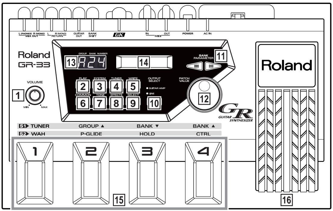
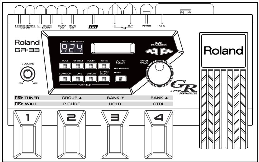
1 VOLUME Knob
The VOLUME knob adjusts the signal volume output from the MIX OUT jack. The center mark provides an easy reference setting when connecting the GR-33 to an instrument amp or mixer.
- The output level from the GUITAR OUT jack is controlled separately.
2 PLAY Button
This button selects Play mode.
To play sounds, press this button to enter Play mode. (The GR-33 is in Play mode at start-up.)
3 SYSTEM Button
This button selects System mode.
Press this button to enter System mode. When you are in System mode, you can make settings to the GR-33 itself, as opposed to making settings for specific sounds.
4 TUNER Button
This button selects Tuner mode.
When you press this button, the Tuner function will be turned on, and you can tune your instrument.
5 WRITE Button
Use this button to write a patch (Patch Write).
This button also confirms the Factory Reset and Bulk Dump operations.
6 COMMON Button
Press this button to access Patch Edit mode's COMMON settings—COMMON settings apply to an entire patch, as opposed to the settings that apply to its individual tones or effects.
Press this button to enter Patch Edit mode and adjust settings such as the patch name and patch pedal functions.
7 TONE Button
Press this button to access Patch Edit mode's TONE settings—TONE settings shape the sound of the individual tones that make up a patch.
8 EFFECTS Button
Press this button to access Patch Edit mode's EFFECTS settings—these settings allow you to adjust the patch's reverb, chorus, and multi-effect.
9 STRING SELECT Button
When selecting and activating the tones to be played in a patch (LAYER), and when setting transposition (TRANSPOSE) and other individual-string settings, use this knob to select the string you wish to set up.
10 OUTPUT SELECT Button
This button selects the output device connected to MIX OUT jacks.
11 BANK/PARAMETER Button
Press these buttons in Play mode to switch patch banks. In System mode and Patch Edit mode, these buttons select the parameter to be adjusted.
12 PATCH/VALUE Dial
In Play mode, turn this dial to scroll through the different patches or tones in order.
In System mode and Patch Edit mode, use this knob to adjust parameter values.
13 Three-digit Display
In Play mode, the three-digit display shows the currently selected patch's number.
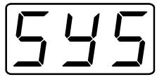
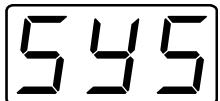
In System mode, Patch Edit mode, and Pedal Effect mode, this display shows "SYS," "Edit," or "PdL," respectively, to indicate the current mode. For parameters that can be set independently for each string, the display indicates the currently selected string's number.
14 Display
In Play mode, the main display shows the currently selected patch's name and the current Harmonist/Arpeggiator status.
In other modes, the display shows the value and status of the currently selected item, or "parameter." Various messages also appear on this display.
15 Foot Pedal
These are four foot-operated switches. In Play mode, together with the GK-2A's "S1," they primarily switch patches. After pressing the GK-2A's "S2" to go into Pedal Effect mode, you can step on a switch to activate performance effects such as wah, pitch glide, and hold.
16 Expression Pedal
Use this pedal to control a variety of things, including the volume, tone and pitch of the current synth sound, and the arpeggiator tempo.
- When you operate the expression pedal, please be careful not to get your fingers pinched between the movable part and the panel.
In households with small children, an adult should provide supervision until the child is capable of following all the rules essential for the safe operation of the unit.


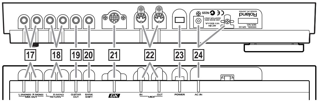
The output of the synthesizer is sent out, or "output," from here. Ordinarily, two cables are plugged into the L and R jacks, and the signal is then sent to a stereo amplifier.
You can use the L (PHONES) jack as a headphone jack for stereo headphones that have a standard 1/4 ” stereo plug—leave the R (MONO) jack unplugged.
You cannot simultaneously use the R (MONO) jack as a mono output while using the L (PHONES) jack as a headphone jack.
When there is nothing connected to the GUITAR OUT jack, the sound of the guitar itself is also mixed into these outputs.
- In order to fully experience the quality of the factory-installed patches, we recommend using a stereo amplifier or stereo headphones. When connecting the GR-33 to a mono amp, use only the R (MONO) jack.
18 GUITAR RETURN Jack L/R(MONO)
When using the GUITAR OUT jack (see below) as an external effect send, use this jack to return the signal. The synthesizer sound and the guitar sound with effects are output together from the MIX OUT jacks.
19 GUITAR OUT Jack
Use this jack when you want the guitar sound to be output from the GR-33 separately from the synth sound. Connect the jack to your guitar amp or guitar effects devices.
20 BANK SHIFT Jack
Use this jack for connecting a patch bank expansion foot switch to the GR-33.
You can connect two Boss FS-5U foot switches using a PCS-31 cable (each sold separately). Expansion foot switches control different functions in all modes except Play mode.
21 GK IN Connector
Use this special 13-pin branch cable, included with the GR-33, to connect the GK-2A divided pickup (sold separately).
- For connection to a guitar designed for use with a synthesizer, consult the guitar's manufacturer or your dealer.
22 MIDI Connectors (MIDI IN/OUT)
Plug MIDI cables into these jacks to connect the GR-33 to an external MIDI device. Do this when you want the GR-33 to control sounds in an external MIDI sound generator module, or to load tone data stored on an external MIDI storage device.
23 Power Switch
This is the switch that turns power to the GR-33 on and off.
24 AC Adapter Jack/Cord Hook
Connect the AC adapter included with the GR-33 to this jack. Hang the adapter cord on the cord hook to help prevent the accidental pulling out of the cord from the jack while you are playing.
- Use ONLY the AC adapter included with this guitar synthesizer.

The explanations in this manual include illustrations that depict what should typically be shown by the display. Note, however, that your unit may incorporate a newer, enhanced version of the system (e.g., includes newer sounds), so what you actually see in the display may not always match what appears in the manual.
Chapter 1 Producing Sounds
What You Need
The following items are necessary for getting sounds from your GR-33:
- GR-33 base module, with included accessories (AC adapter, 13-pin cable)
- Amplifier, speakers, and cables—a completely stereophonic system is preferable—or stereo headphones
- GK-2A divided pickup
Metal-stringed guitar with GK-2A properly installed
In addition to the above items, you should also have the following items on hand if needed:
- Guitar amplifier, guitar effects (for adding to guitar sounds)
- External bank shift switches (Boss FS-5U, optional) — to use two foot switches, a branch cable (stereo x 1 → mono x 2, 1/4" phone plugs) is required (p. 23)
- MIDI foot controller (FC-200 or similar unit, optional) (p. 24)
Installing the GK-2A
Before you can use your guitar with the GR-33, the GK-2A must first be properly installed on the guitar.
Following the procedure outlined in the GK-2A owner's manual, attach the GK-2A's pickup as shown in the picture.
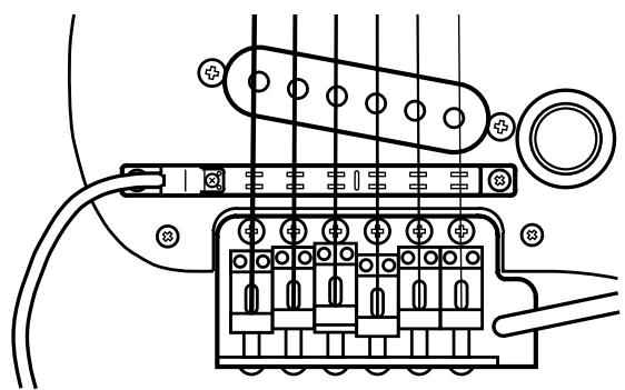
- Be sure the Divided Pickup is correctly oriented: the cord from the Pickup should emerge from under the sixth string.
- Assembly instructions for use of the GK-2A with the other device may appear in the GK-2A owner's manual. Installation for use with the GR-33 follows the same logic.
To confirm the quality of the GK-2A installation, please take special note of the following points:
- Make sure that the space between each string and its pickup is exactly 1mm when you press the top fret. (Do not allow the string to get too close to the pickup.)
- Do not allow the space between the guitar bridge and the GK-2A pickups to exceed 20 ~mm .
- Make sure that the placement of each of the pickups' six yokes (pole pieces) in relation to each string is correct.
For more detailed instructions, please refer to the GK-2A owner's manual.
Guitars That Cannot Be Used with the GK-2A
While the compact design of the GK-2A allows its installation on many different guitars, please note the following types of guitars on which it cannot be used:
a. 12-string, pedal steel, and other specially strung guitars; nylon-strung, gut-strung, and similar guitars; bass guitars. (The GK-2A will not operate successfully if installed on such instruments.)
b. Guitars which, due to their physical design, lack the space for proper mounting of the GK-2A.
Regarding situation “b.” above: You may be able to install the GK-2A after a minor modification of the guitar. Please consult the dealer where you purchased your GK-2A.
MEMO
Some guitar manufacturers are currently shipping guitars that can be connected directly to the GR series with a 13-pin cable, without the use of a GK-2A. For more information, please ask your dealer or these guitar manufacturers.
- Take care when dealing with guitars that have more than 25 frets, or unusually high tunings, as the response around the upper frets may not be sufficient for taking full advantage of the GR-33.
Making Connections
After setting up the guitar part of your system, connect your other equipment following the examples shown in the connection diagram below.
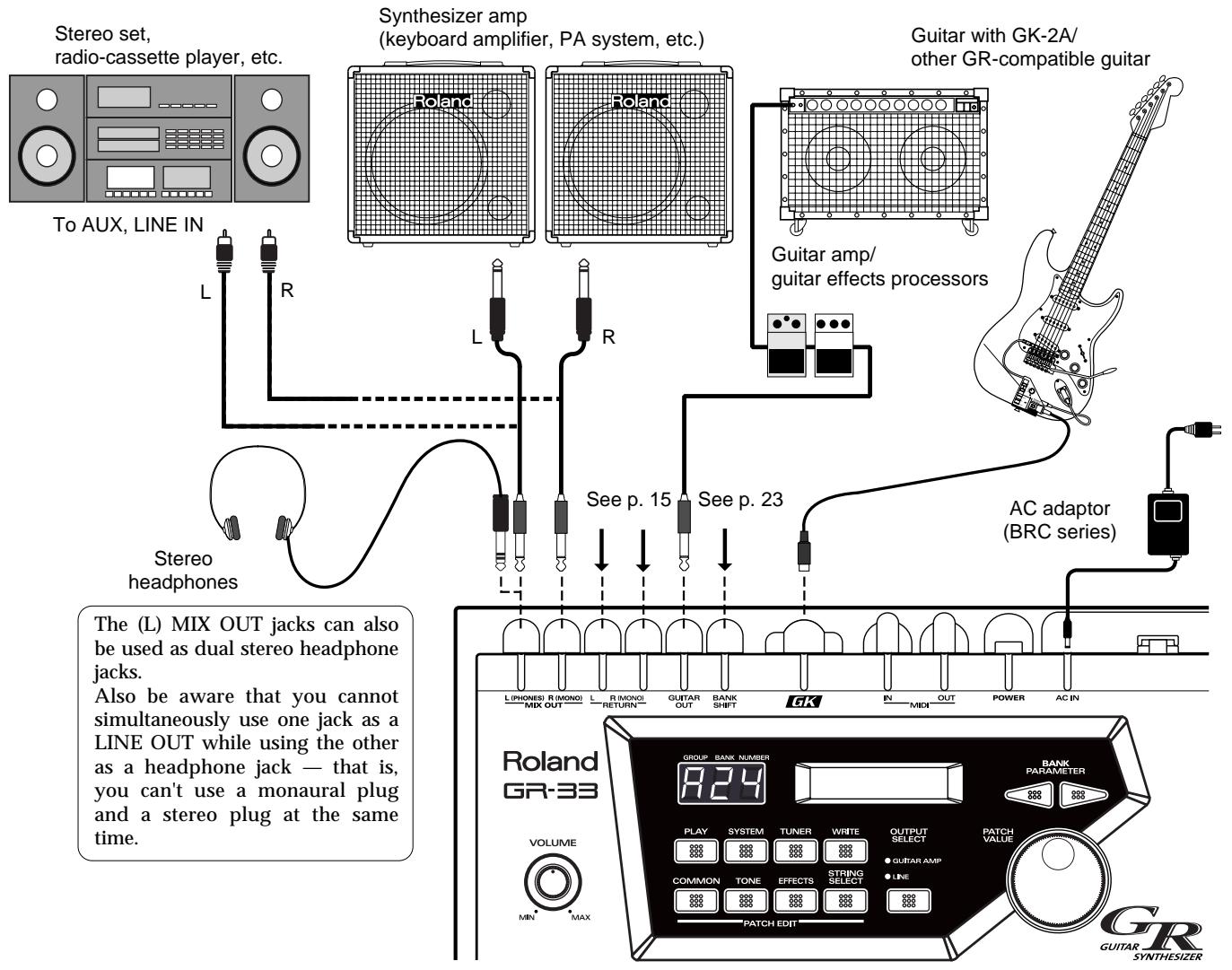
- To prevent malfunction and/or damage to speakers or other devices, always turn down the volume and turn off the power on all devices before making any connections.
- Raise the volume of the amplifier only after you turn on the power to all connected devices.
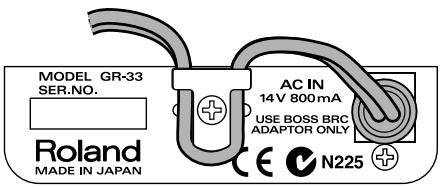
- To prevent the inadvertent disruption of power to your unit—as a result of the plug being pulled out accidentally—and to avoid applying undue stress to the AC adapter jack, anchor the power cord using the cord hook as shown in the illustration.
- If you are outputting a mono signal from the GR-33, connect the cable to the R (MONO) jack of the MIX OUT jacks.

To get the optimal performance from the GR-33, and to fully experience the quality of its patches, connect your setup to a stereo (two-channel) amplifier/speaker system, or to stereo headphones. Stereo equipment is the best way to hear the fullness of the GR-33's sound.
Outputting the guitar sound and synth sound separately
You can connect a general-purpose shielded cable to the GUITAR OUT jack to add external guitar effects or to send your guitar sound to your guitar amplifier. With this arrangement, you can control the sound of the guitar exactly the same way you would if the guitar were not connected to the GR-33. The synthesizer sound — without the guitar sound mixed in—will be output from the MIX OUT jacks.
Outputting the guitar sound and synth sound together
Connect cables only to the MIX OUT jacks—do not connect a cable to the GUITAR OUT jack. The sound of the guitar itself will be output along with the synth sound from the MIX OUT jacks. This way, both guitar and synthesizer sounds can be played through a single stereo (or mono, if necessary) amp.
Applying an external effect only to the guitar sound and outputting it along with the synth sound
Make the following connections.
GR-33 GUITAR OUT Jack
↓
External Effect Input
External Effect Output
↓
GR-33 GUITAR RETURN Jack
The synthesizer sound and the guitar sound with effects are output together from the MIX OUT jacks.
Listening through headphones
Make sure nothing is plugged into the L (MONO) MIX OUT jack, and connect a set of stereo headphones to the R (PHONES) jack.
- You cannot simultaneously use the R (MONO) jack as a LINE OUT while using the L (PHONES) jack as a headphone jack—that is, you can't use a monaural plug and a stereo plug at the same time.

For settings appropriate to your output device, refer to "Specifying the output device (OUTPUT SELECT)" (p. 19).
Necessary Steps—From Powering Up to Performance
- Once your connections have been completed (p. 14), turn on power to your various devices in the order specified. By turning on the devices in the wrong order, you risk causing malfunction and/or damage to speakers and other devices.
After you have finished checking your connections, turn the GR-33's VOLUME knob all the way counterclockwise—thus turning its volume all the way down—and press the power switch on the rear panel to turn on the GR-33.
(Pressing the switch again turns the power off.)

If you wish, use the procedure described in "Reset to Default Factory Settings (Factory Reset)" (p. 16) to return the GR-33's settings to their original values before beginning.
- This unit is equipped with a protection circuit. A brief interval (a few seconds) after power up is required before the unit will operate normally.
About Play Mode
After turning on the GR-33, confirm that "A11" appears in the three-digit display window. This is the number of the currently selected patch. Each patch contains a pair of tones that can you can switch with a pedal, etc. during performance. ( For details, see p. 21.)
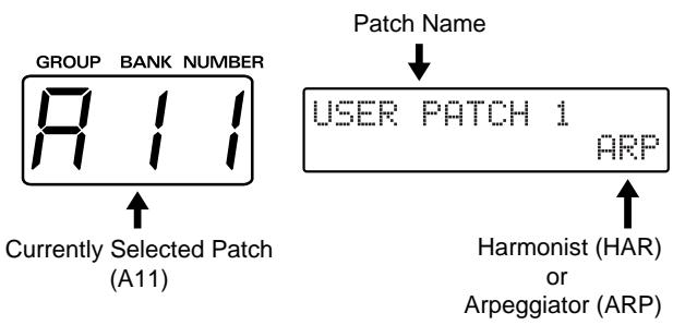

When a patch number—such as the "A11" that appears right after the power is turned on—is shown in the display, you are in Play mode. You will typically be in Play mode as you perform. Play mode is the basic state of the GR-33.
Until you are familiar with how everything in the GR-33 works, remember this: You can always return to Play mode by turning the power off and then on again.
(For more about how the dials and buttons work in Play mode, please see p. 30.)
Reset to Default Factory Settings (Factory Reset)

The procedure for restoring the GR-33's internal settings to the state they were in when the unit left the factory is called a "Factory Reset."
At the time of purchase, the GR-33's user patches (A11 to D84) are the same as preset patches E11 to H84. These patches, as well as the GR-33's system settings—including pickup sensitivity and the MIDI channels used for sending and receiving MIDI data—can be returned to their original factory-fresh state.

The Factory Reset operation undoes any settings you have changed and discards any edits you have made to its patches. If you have settings or patches you wish to preserve, use the Bulk Dump operation (p. 37) to save them to an external MIDI device, such as a sequencer, before performing the Factory Reset operation.
Performing a Factory Reset
- Press [SYSTEM] to enter System mode.
- Press [PARAMETER] to select "FACTORY RESET."
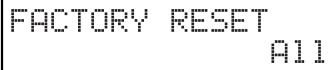
-
Turn [VALUE] to select the parameter—or group of parameters—you wish to reset.
-
All: Restores all settings to their original state.
- System: The System settings will be restored to their factory settings.
- User Patch: Patch settings will be restored to their original state.
- PC Number: Program Change numbers are re-assigned according to the current order of the patches.

For more detailed information about the "PC Number," refer to "Re-assigning Program Change Numbers in the Order of Patches" (p. 97).
- When you have selected the desired parameters, press [WRITE].
The message "Sure ?" appears, asking you to confirm that you want to go ahead and perform the Factory Reset operation.
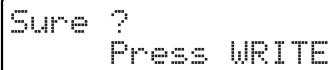
- To execute the operation, press [WRITE] again.
"Now Writing..." appears in the display. In a moment, the GR-33 automatically returns to Play mode, completing the factory Reset.
To cancel the operation, press [PLAY].
- This means that the processing of data is in progress. Once you press [WRITE], be sure not to turn off the power until to return to Play mode.
Overall Settings for the GR-33 (SYSTEM)
Adjusting the Brightness of the Display (LCD Contrast)
Adjusting the Brightness of the Display
- Press [SYSTEM] to enter System mode.
- Press [PARAMETER] to select "LCD CONTRAST."
LCD CONTRAST
8
- Turn [VALUE] to adjust the contrast.
- When you have finished adjusting the display, press [PLAY] to return to Play mode.
Setting Input Sensitivity (PICKUP SENS)
With the power turned on, adjust the input sensitivity of each string according to how the GK-2A is mounted and to match your own picking strength. Since these settings are stored automatically—and will not be lost even if the power is turned off—it is not necessary to reset the sensitivity each time you play.
Procedure for Setting Input Sensitivity
- Press [SYSTEM] to enter System mode.
- Press [PARAMETER] to select "PICKUP SENS."
Sensitivity-setting is activated, and the following appears in the display window:
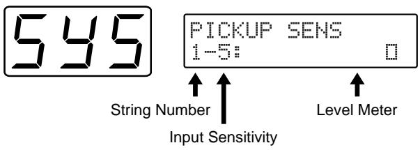
- When String 6 of the guitar is played, the string number in the display automatically switches to "6." The level meter shown in the display will light from the left, showing how strongly the string is played. The current input-sensitivity setting for the string will also be displayed next to the string number.
- Use [VALUE] to adjust the sensitivity so that the square indicator lights when you play most strongly in actual performance.
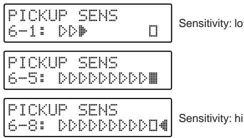
If the indicator furthest to the left is lit, the level is set too high, so turn [VALUE] to lower the sensitivity.
-
If the sensitivity is set too high, there may be dropouts in the sound, or the response to dynamic changes in your playing may be reduced. Setting sensitivity too low may also result in problems, so make this adjustment carefully.
-
Adjust Strings 5 to 1 using the same technique.
- When you have finished, press [PLAY] to return to Play mode.
In any of the following situations, please be sure to readjust the sensitivity settings!
- When using a guitar for which you have not yet made sensitivity adjustments
After performing a Factory Reset (p. 16) - When you change the mounting of the GK-2A to accommodate a change in the guitar, such as when string height has been readjusted
- When you replace a string with one of a different gauge In some rare cases, the sensitivity meter may show too high a reading even with sensitivity at its lowest setting. If this does occur, widen the space slightly between the GK-2A's separate pickups and the strings.
Using Multiple Guitars (GUITAR SELECT)
You can store four separate string-sensitivity setups that can be called up to match any of four guitars you are currently using.
■ Calling Up the Different Sensitivity Settings
- Press [SYSTEM] to enter System mode.
- Press [PARAMETER] to select "GUITAR SELECT."
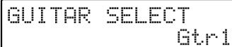
- Turn [VALUE] to select Gtr1-Gtr4.
The setting you select will be loaded.
- With the factory settings, this is set to "Gtr1."
If you wish to create a new input-sensitivity setup, press [PARAMETER] to select "PICKUP SENS," and then adjust the sensitivity settings for the current guitar's six strings. - After setting each string's sensitivity, press [PLAY] to return to Play mode.
Create four different input-sensitivity setups for Gtr1-Gtr4 to store the sensitivity settings for four different guitars. - The last-selected sensitivity setup is the one currently in effect.
Matching Pitches of Other Instruments
The master tuning (basic pitch) set at the factory for the GR-33's sounds and internal tuner is A = 440.0Hz .
If you need to match the GR-33's tuning to the tuning of another instrument—or if you want to change the master tuning for any other reason—perform the following steps.
Changing the Master Tune Setting
- Press [SYSTEM] to enter System mode.
- Press [PARAMETER] to select "MASTER TUNE."
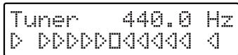
MASTER TUNE 440.0 Hz
- Turn [VALUE] to select the desired pitch. The pitch can be changed to any frequency from 427.4 to 452.6Hz .
-
Press [PLAY] to return to Play mode.
-
The pitch of the synthesizer sound does not change when you change the GR-33's Master Tune setting—the synth sound continues to follow the tuning of the guitar. Therefore, after adjusting the master tuning, you should use the Tuner function to re-tune your guitar to the new basic pitch, and the pitch of the synth sounds will play in the new tuning.
Adjusting the Guitar Tuning (Tuner Function)
To accurately set a guitar's pitch, use the GR-33's built-in tuner to tune the guitar. This tuner works exactly the same way other tuners on the market do.
Tuning the Guitar
- While pressing [S1] on the GK-2A, step on the first foot pedal—[1] (TUNER)—or press [TUNER].
The Tuner function is called up, and the following appears in the display.
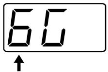
String Numbers 1 to 6
- Play String 6 on the guitar.
The string number automatically switches to "6."
The note to which String 6 is currently tuned—notes are tuned by semitones—is shown in the second position on the display. ("D#" in the figure shown below.)
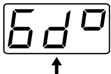
Pitch name
("D#" - The marking in the third place denotes sharp)
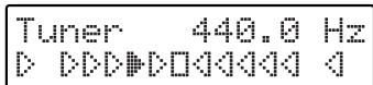
- Turn the string's tuning peg while playing String 6 until the screen shows the name of the note to which you want to tune the string.
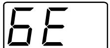
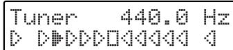
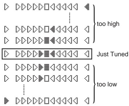
- Make fine adjustments to the string's tuning peg until the mark illuminated in the display moves to the center position and both side.
When the center indicator lights, String 6 is tuned precisely to "E."
- Tune each of the other strings, 5 to 1, to A, D, G, B, and E, respectively.
- When you are finished tuning, press any foot pedal, [S1] or [S2] on the GK-2A, or [PLAY], to return to Play mode.
Selecting the output device (OUTPUT SELECT)
In order for the GR-33 to produce the correct output levels, you must select the type of device to which its outputs are connected (MIX OUT).
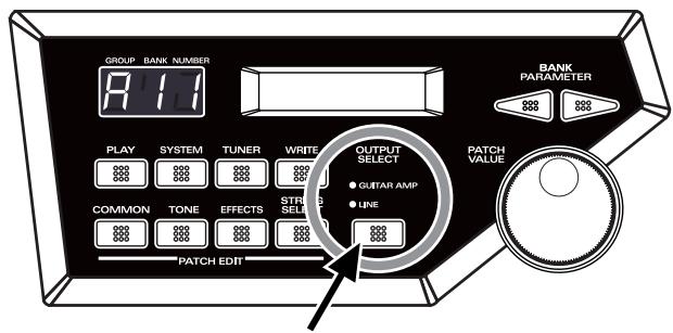
1. Press [OUTPUT SELECT] and select the appropriate setting.
The currently selected setting will light.
GUITAR AMP:
Select this when using a dedicated guitar amp.
LINE:
Select this when using a keyboard amp, general-purpose instrument amp, mixer, MTR, or headphones.
HINT
The GR-33's sound generator is a PCM synthesizer that can reproduce a wide range of timbres. To optimally capture its rich synthesizer sounds, use a keyboard amp, other general instrument amplifier, PA system, or other such equipment instead of a guitar amplifier if possible.
- Changing the OUTPUT SELECT setting will not affect the settings that are stored in each patch.
Turning off the guitar amp simulator (G.AMP SIM)
The GR-33 has a built-in guitar amp simulator (G.AMP SIM). If OUTPUT SELECT is set to "LINE," the guitar amp simulator will be applied only to the guitar sound itself. This allows you to create the illusion of the original guitar sound being played through a guitar amp, even when it is being fed directly into another device.
If you are not using the GR-33's internal guitar amp simulator—if you are using an external amp simulator effect device, for example—set the GR-33 as follows.
Turning the Amp Simulator Off
- Press [SYSTEM] to enter System mode.
- Press [PARAMETER] to select "G.AMP SIM"
G.AMP SIM
On
3. Turn [VALUE] to select "Off."
- Off:
The amp simulator will not be used.
On:
The amp simulator will be used when OUTPUT SELECT is set to "LINE."
4. Press [PLAY] to return to Play mode.
- When you once again wish to use the amp simulator, select "On" in Step 3.
Playing the Internal Synth Sounds with the Guitar
After checking the connections to the amplifier you are using, completing the sensitivity setup and tuning your guitar, try playing some sounds.
How to Play the GR-33's Sounds with the Guitar
- Make sure that the display indicates Play mode (p. 15).
- Set the GK-2A's selector switch to "SYNTH."
- Turn SYNTH VOL on the GK-2A counterclockwise to raise the volume to a suitable level.
- Set the VOLUME knob on the GR-33 to its center position.
- When you press Pedal 3, the number in the display changes to "A13," and the corresponding patch (sound) is selected.
You are now ready to play. Play your guitar while gradually turning up the volume on your amplifier, and you will hear the selected patch—patch A13—from the GR-33's internal sound generator.
To Hear the Normal Guitar Sound...
Set the GK-2A's selector switch to "MIX." If you then switch to "GUITAR," the synthesizer sound generator will be muted, and only the sound of the guitar will remain.
To Change the Volume of the Synth Sound Generator...
Adjust the volume using either the SYNTH VOL knob on the GK-2A or the GR-33's VOLUME knob.

Turning the GR-33's VOLUME knob changes the overall volume output from the MIX OUT jacks. Thus, when the guitar sound is included in the MIX OUT signal, both guitar and synthesizer sound levels are changed. (The guitar sound output from the GUITAR OUT jack is not affected. The guitar volume is also unchanged when you use the GK-2A's SYNTH VOL knob.)
What To Do if There is No Sound When the Guitar is Played
First, check the following:
- Check to see that amplifier and other equipment volume levels are correct, and confirm that all the equipment is properly connected (p. 14).
- Make sure the volume on both the GR-33 and the GK-2A are up. Also, make sure that the guitar/synth switch is not set to GUITAR.
When the Sound of a Specified Patch Fails to Play on All the Strings (or on a Particular String)
- Try pressing the expression pedal (p. 11) as far down as it will go.
- When using a monaural connection to your amp, be sure to connect your cable to the R (MONO) jack of the GR-33 MIX OUT jacks.
- Confirm that the synth sounds have not been muted for any strings in the TONE "LAYER" parameter in Patch Edit mode (p. 51).

If the volume levels of the strings vary widely, please recheck your input sensitivity (PICKUP SENS) settings (p. 17).
Chapter 2 Selecting and Playing Sounds (Patches)
What Is a Patch?
"Patch" is the term for the GR-33's tones that can be called up at any time with a foot switch or other device. There are 256 patches stored in the GR-33. As an example, the "A11" that appears in the display when the power is switched on indicates that patch number A11 has been called up, and that the unit is ready to be played.
This unit's basic unit of sound is the "tone." Tones consist of sound waveforms, such as "GR Piano," "Pipe Organ," and "Nylon Gtr mp" A total of 384 such tones are provided onboard. (How to choose tones p. 49; list of tones p. 122)
In any patch, up to two selected tones are combined, and then various settings and adjustments, such as brightness, attack, difference between synthesizer and guitar pitch, and the like are made. The user has full freedom to make these settings and adjustments so that the patch may best suit the song to be played.
Another result of changing these settings is that you can write and store 128 patches (in the first half of the patch bank). (For more detailed information about patches, please refer to p. 35.)
Patch numbers are indicated by a three-digit code: “a letter of the alphabet A-H (Group),” followed by “a numeral 1 to 8 (Bank),” and then “a numeral 1 to 4 (number on the pedal).” (Example: A83, d24, F61, etc.)
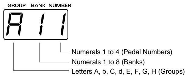

Consecutive numerals 001 to 256 can also be substituted (p. 24).
Selecting a Patch
Using the Guitar (GK-2A) to Select Patches
Sometimes (such as when you want to listen to all of the patches one after the order) you will want to select patches using only the guitar (GK-2A). In such cases, follow the steps below. (It is unnecessary to touch any pedal or anything else on the base module.)
Rewritable Patches (User Patches)
Patches in Groups A through d
(A11 to A84, b11 to b84, C11 to C84, and d11 to d84)
Here you can create patches to fit a song, or for other purposes, and then store those patches in memory.
(When you purchased your GR-33, the patches stored in these groups were the same as the following preset patches. If you want to reset the GR-33 patches to the original conditions, please carry out the Factory Reset operation explained on p. 16.)
Read-only Patches (Preset Patches)
Patches in Groups E through H
(E11 to E84, F11 to F84, G11 to G84, and H11 to H84)
This is a collection of 128 preset patches, which have already been completely prepared by Roland. These patches are read-only, so although they can be changed, they cannot be written over with another patch. However, this also means no worries that they might be erased accidentally.
Preset patches are called up and used in the manner as user patches. Furthermore, they are convenient as references and basic material for the user wishing to create original patches.
How to Select a Patch Using the Guitar
- Press [SYSTEM] to enter System mode.
- Press [PARAMETER] to select "S1/S2 FUNCTION."
S1/S2 FUNCTION Normal
-
Use [VALUE] to select "Patch Select."
-
Patch Select:
You can continuously switch patches with [S1] and [S2] on the GK-2A.
Normal:
Normal status. You cannot switch patches on the GK-2A. -
Press [PLAY] to return to Play mode.
- Pressing the GK-2A [UP/S2] once brings you to the next higher patch; by holding the switch down, you can switch continuously. Furthermore, when the other button (here the [DOWN/S1] button) is then also pressed, the switching occurs even faster. Pressing the [S1] and [S2] buttons in the reverse fashion will similarly return you to previous patches.
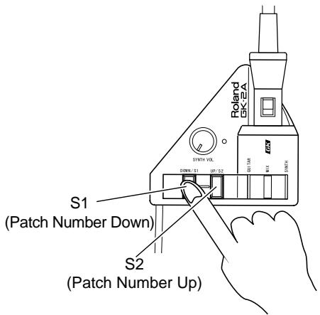
Now, using the GK-2A buttons to switch patches, try playing the guitar to listen to the patches in sequence.
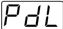
With the GR-33 in the state just described, you can get various pedal effects (explained later). For example hold, pitch glide, and the like can be obtained, by stepping on the base unit's four pedals. (For details, see p. 28.) To indicate this status, when "S1/S2 FUNCTION" is selected in "Patch Select," the "PdL" display appears (approximately once every four seconds) in the three-digit display, showing the patches and their corresponding numbers.
USER PATCH 1
Additionally, with the unit in this status, an external bank shift pedal can be used to change patch numbers, both up and down, just like the [S1] and [S2] buttons on the GK-2A.
Using the Base Module to Select Patches
Selecting Patches Using the Pedal
You can select patches using the pedal only when "S1/S2 FUNCTION" is set to "Normal."

For the "S1/S2 FUNCTION" settings, refer to p. 21.
To Use the Pedal for Calling Up Patches from the Same Group or Bank
When playing live or in the studio, by using the pedal on the base module, you can instantly select one of four patches from the same group or bank.
- Make sure that you are in the Play mode.
If you are not in the Play mode, press [PLAY]. - When you press pedals 1 to 4, you can instantly select a patch from the same bank of four patches in a group, with the number at the right in the display changing to show the number of the pedal currently pressed.
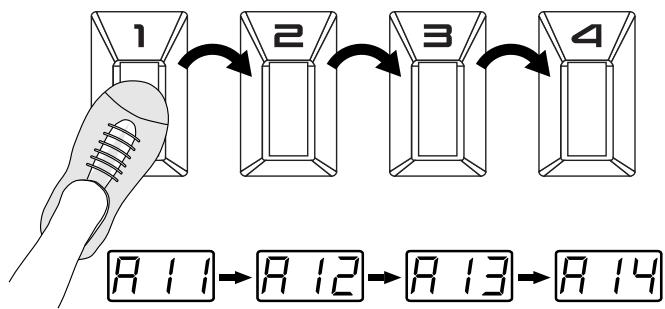
To Use the Pedal for Calling Up Patches from a Different Group or Bank
Used together with the GK-2A's [S1] button, you can use the pedal function to switch patches.
- Make sure that you are in the Play mode.
If you are not in the Play mode, press [PLAY].
- While pressing [S1] on the GK-2A, step on [GROUP ] (pedal 2).
Pedal 2 continues switching to the next group only while [S1] is being held; pressing the pedal allows you to progress to the next group.
- If you wish to change only the bank without changing the group, omit step 2, and proceed to step 3.
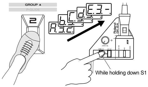
3. While pressing [S1] on the GK-2A, step on [BANK (pedal 4) or [BANK ] (pedal 3).
As long as the [S1] button is held down, pedal 4 works as a [BANK ] (BANK UP), and pedal 3 as a [BANK ] (BANK DOWN). The display starts to flash, and when you step on pedal 3 or 4, numbers for the bank digit (the middle number in the display) go down or up.
![ROLAND GR-33 - While pressing [S1] on the GK-2A, step on [BANK (pedal 4) or [BANK ] (pedal 3). - 1](/content/2025/01/130734/images/62bbdaf048e096cd4727cf0c3b56ebca82e17ed59df0b632bf0e3c81687b3319.jpg)
4. After selecting the desired group/bank, release [S1], then step on the pedals.
When you press a pedal, the patch will be finalized, and the sound will change.
![ROLAND GR-33 - After selecting the desired group/bank, release [S1], then step on the pedals. - 1](/content/2025/01/130734/images/98c052d3a42c713cbaa0eb9fc09156efa5bd2c2b77f9155e748906ca2993491c.jpg)
Selecting with the Dial
If you wish to use the dial to select patches, you must make the following setting for the dial.
- Press [SYSTEM] to enter System mode.
- Press [PARAMETER] to select "DIAL FUNCTION."
DIAL FUNCTION PATCH & VALUE
3. Use [VALUE] to select "PACK&VALUE."
- PATCH&VALUE:
The dial can be used both for selecting the patch number and for modifying values while editing. - VALUE Only:
The dial can be used only for modifying values while editing.
4. After making the setting, press [PLAY] to return to Play mode.
In Play mode, you can rotate the [VALUE] dial to select all 256 patches A11-H84.
You can also use [BANK/PARAMETER] to move forward/backward through the banks.
Using the Base Module plus an External Foot Switch to Select Patches
By plugging a foot switch into the BANK SHIFT jack on the rear panel, you can switch banks without pressing [S1] on the GK-2A.
With one DP-5 (sold separately) to rise through patch bank numbers, or with two Boss FS-5U foot switches and a branch cable (sold separately) to move both up and down through the patch banks, it's possible to perform this procedure using only your feet.
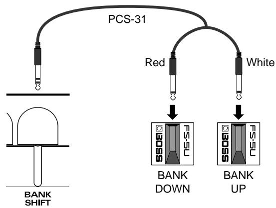
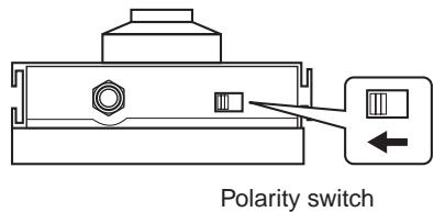
- Sometimes when pressing and releasing the foot switch to switch banks, you may find that while the bank does change, the patch number may not (light will flash); however, this does not indicate any malfunction. You can also make the setting with the FS-5U polarity switch, as shown in the figure below.
- If the "S1/S2 FUNCTION" has been set to "Patch Select," the action of the foot switch just described changes to switching patches up and down (p. 21).
Selecting Patches with an External MIDI Foot Controller
While the base module's four pedals are being used as designated pedals (p. 26) for such effects as hold and wah, you may also wish to switch patches using your foot. In such cases, you should hook up an external MIDI foot controller (e.g. FC-200, Boss FC-50, and so on). Make the settings, using the following procedure.
- Connect equipment as shown in the figure below.
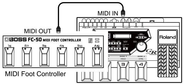
- Press [SYSTEM] to enter System mode.
The patch number display corresponds to the display on the MIDI foot controller, but with numbers 001 to 256 instead of the alphanumeric symbols in patch numbers used by the GR-33.
- Press [PARAMETER] to select "DISPLAY TYPE."
DISPLAY TYPE Grp/Brk/Num
-
Use [VALUE] to select "Decimal."
-
Decimal:
Patch numbers will be displayed as a decimal number in the range of 001-256.
- Grp/Bnk/Num:
Patch numbers will be displayed as a group/bank/ number from A11-H84.
- Press [PARAMETER] to select "S1/S2 FUNCTION."
- Use [VALUE] to select "Patch Select."

For details, refer to "Selecting a Patch/Using the Guitar (GK2A) to Select Patches."
- Press [PLAY] to return to Play mode.
The patch number displayed will be "001," rather than "A11." - Set the MIDI send channel of the MIDI foot controller to match the channel of the GR-33 (p. 86; the factory setting is channel Mono 11).
-
Use the MIDI foot controller to switch patches externally, operating the controller according to the instructions in the owner's manual.
-
The patch number using the numeral-only format that was set in step 4 is stored in memory even after the power is turned off. If necessary, return the patch number display to the Group/bank/number format. Additionally, user patches (001 to 128, or A11 to D84) can usually be selected when MIDI program change data is sent from the MIDI foot controller immediately after the power is turned on.
- MIDI program change numbers received by the GR-33 have a fixed one-to-one correspondence with the patches (001 to 128, or A11 to D84) they represent; this cannot be changed. (On the other hand, when patches are selected using the GR-33, you have the freedom to change and save the MIDI program change numbers that send the data to outside equipment. p. 88)
Changing the Patch Order
When sequencing patches while performing a piece, or while you are on stage, if the patches are from the same group/ bank (for example A11 to A14), you can switch patches very smoothly by using the pedals on the base module.
To change the order of the patches, perform the patch write (p. 36) operation. This designates the patch number (address) where the patch data from the present selection (or change) will be written.
Example: To change the contents of A21 and B62
First, to prevent the contents of patch A21 from being lost, clear a patch number that is not being used. (Since groups A through d of user patches are the same as groups E through H of preset patches, you may erase them without worry.)
After that, by writing B62 A21 , then temporary placeholder B62 , the order of A21 and B62 can be swapped.
- Select the "A21" patch.
2. Press [WRITE].
You enter Write mode, and the screen like the one below appears.
![ROLAND GR-33 - Press [WRITE]. - 1](/content/2025/01/130734/images/198ce5912a6edc57dd5336a01a6cb37686f91d68b92aef1bbdcbf1f6f47b9b8e.jpg)
Write to A21
3. Use [VALUE] to select the patch you want to write to.
![ROLAND GR-33 - Use [VALUE] to select the patch you want to write to. - 1](/content/2025/01/130734/images/4b0d6e1cedc0225b24b84bf5033af6d34b0cb3ead22094adb95ecb5c50a1ce34.jpg)
Write to C11
In this example, we will use "C11" as the writing destination patch.
4. After you have specified the writing destination patch, press [WRITE].
The following display will appear, asking you to confirm the operation.
![ROLAND GR-33 - After you have specified the writing destination patch, press [WRITE]. - 1](/content/2025/01/130734/images/e1547e3aab100bc8ceee3cba0d3be72028212d4ed89d658f1ffb3ad6716e2321.jpg)
Sure? Press WRITE
5. After making sure that you want to execute this operation, press [WRITE] once again.
![ROLAND GR-33 - After making sure that you want to execute this operation, press [WRITE] once again. - 1](/content/2025/01/130734/images/5a8bd35c1251ec4df25e51921bd551da2ba6f306cd3aab0ecb0927478134b94b.jpg)
Now writing...
"Now Writing..." appears in the display, the unit automatically returns to the Play mode, completing the writing procedure.
6. Using steps 1 to 5 above, write B62 A21 just as you did A21 temporary place-holder (C11).
7. Complete the rearrangement by using the same process to write the temporary place-holder (C11) B62
- Since patch groups E through H are read-only, you cannot rearrange their order or create temporary place-holders with them. (However, you can copy them for reference or to use them as starting material when writing new patches.)
Chapter 3 Controlling Functions and Effects with the Base Module Pedals
"Pedal Effect Mode": What It Is, and How to Call It Up

About Pedal Effect Mode
By using the four pedals on the GR-33, you can turn on and off the Arpeggiator (and Harmonist) function, and get effects such as synth sound hold and wah pedal. This is called "Pedal Effect mode," and along with the Play mode, is often used in performance.
How to Switch to Pedal Effect Mode
- Press [SYSTEM] to enter System mode, and set the "S1/ S2 FUNCTION" to "Normal."

For more detailed information and instructions for this procedure, refer to "Selecting a Patch/Using the Guitar (GK-2A) to Select Patches" (p. 21).
- Press [PLAY] to return to Play mode.
- Press [S2] on the GK-2A once.
As you enter Pedal Effect mode, "PdL" (Pedal) will start to blink in the GR-33's three-digit display.
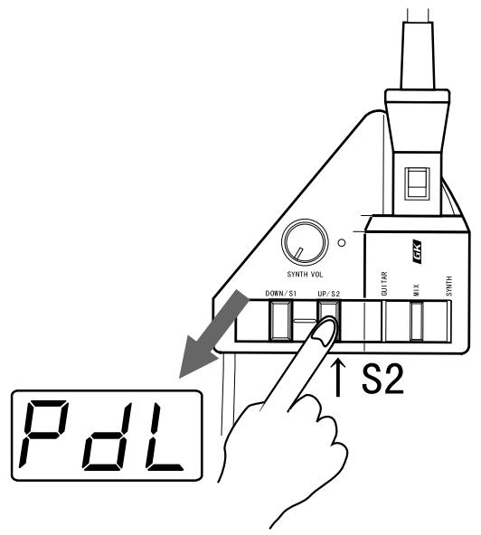
Press either [S1] or [S2] on the GK-2A to return to Play mode.
The same pedal can produce different effect amounts from patch to patch. These can be changed to suit a song—or for any other purpose—and can be saved as part of the patch.
For more information about each pedal effect function, and to learn how to change the effect amount, please see Chapter 5 (p. 35-52).
Getting the Same Effect While in Play Mode
If you have set "S1/S2 FUNCTION" in System mode to "Patch Select" in order to use the buttons of the GK-2A for selecting patches, you can use pedal effects in Play mode. The four pedals will act as they do in Pedal Effect mode instead of selecting patches as they normally would in Play mode. ("PdL" will appear once every four seconds or so in the 3-digit display, indicating that pedal effects are available.)

For more detailed information and instructions about this type of setup, refer to "Selecting a Patch/Using the Guitar (GK-2A) to Select Patches" (p. 21).
- With the exception of the arpeggio latch hold (p. 76), pressing more than one pedal at the same time can result in unexpected behavior, so please exercise due caution.
Turning Arpeggiator and Harmonist On/Off

About MULTI-FX
These are effects for the synthesizer sound.

For details, refer to p. 53.

About Arpeggiator
This is a function that automatically creates arpeggios — chords whose notes are played in sequence, rather than simultaneously — when a chord is played.

For details, refer to p. 76.

About Harmonist
This creates harmonies in designated keys using either guitar and synthesizer sounds, or two synthesizer sounds together.

For details, refer to p. 80.
The GR-33 comes with Multi-Effects, Arpeggiator, and Harmonist functions that can be turned on and off using the pedals.
- The MULTI-FX Bypass, Arpeggiator and Harmonist can be turned on or off individually for each Patch. To learn about these settings, refer to p. 46.
- You may hear a noise when MULTI-FX BYPASS is switched on/off, but this does not indicate a malfunction.
Using the pedals for on/off switching
- Enter Pedal Effect mode (p. 26). (As an alternative, set System mode "S1/S2 ACTION" to "Patch Select" and return to Play mode.)
- Press Pedal 4 (CTRL).
The specified function—MULTI-FX BYPASS, Arpeggiator, or Harmonist—will be switched on or off. This selection can be made by the Patch Edit mode "COMMON" setting "CTRL PEDAL" (p. 46).
MULTI FX BYPASS On/Off
"bYP" or "oFF" appears for approximateryone second in the three-digit display.
Arpeggiator On/Off
"Arp" or "oFF" appears for approximateryone second in the three-digit display.
The display responds as shown below when the Arpeggiator is being turned on.
USER PATCH 1
ARP
Harmonist On/Off
"HAr" or "oFF" appears for approximately one second in the three-digit display.
The display responds as shown below when the Harmonist is being turned on.
USER PATCH 1
HAR(F#m)
Key
Either the Arpeggiator or Harmonist—but not both—can be selected for a patch. Even when they are turned off, either the Arpeggiator or Harmonist is still selected. When the Arpeggiator (Harmonist) is turned on, the display of the Play mode shows "ARP" or "HAR" to indicate which one currently selected.. If the harmonist is selected, the currently selected key will also be displayed.
- When you want to switch from Arpeggiator in a certain patch to Harmonist (or vice versa), press [EFFECTS] to change the "HAR/ARP SELECT" setting.

For more detailed information and instructions for this procedure, refer to p. 78 and 82.
Changing Effects with the Pedals
In Pedal Effect mode (p. 26), you can get different effects by pressing Pedals 1 to 4 in the follow way.
Getting a Pedal Wah Effect (Wah)
You can get several of the most commonly used wah effects by pressing Pedal 1 (WAH). Repeatedly pressing and releasing the pedal produces changes in the sound resembling those produced by a guitar wah-wah pedal, allowing you to apply this effect to synthesizer sounds.
You can choose from a number of pre-programmed variations that use different combinations of rate of sound change, degree of change, panning, how different the sound becomes, and so on. These can then be saved in each patch. In addition, when you select "Modulation" in "WAH TYPE," you will hear a deep vibrato (undulating or wavering pitch) when the pedal is pressed instead of wah-type effects. This creates the mechanical-sounding vibrato characteristic of synths — if you prefer, you can create a more natural-sounding vibrato using your guitar fingering.

For more detailed information and instructions for this procedure, refer to "Selecting Wah Types (WAH TYPE)" (p. 43).
- You may find that when you first press Pedal 1 (WAH), the sound is different than when the patch was first selected. The sound may be muffled, or have a strange quality to it. Return to the original patch, switch to a different patch, and then return to the original patch again. If a bank shift pedal is connected, you can return to the original patch by pressing the bank down pedal while still in Pedal Effect mode.
Changing Pitch Dynamically (Pitch Glide)
Press Pedal 2 (P-GLIDE) to get a pitch glide effect. This effect creates continuous changes in pitch over variable time intervals, long or short. With chords—since you can glide while maintaining the harmonic intervals within the chord—this differs from a guitar's vibrato arm/vibrato bar/whammy bar, providing a unique effect.
As for the time duration and glide intervals, you can select from seven pre-programmed pitch rise and fall patterns, and then save them in patches.

For more detailed information and instructions for this procedure, refer to "Selecting Pitch Glide Type (GLIDE TYPE)" (p. 44).
- Depending on the selected tone, the tone settings, and performance conditions, the width of the effect may be limited.
Holding a Synth Tone After the String is Stopped (Hold)
Press Pedal 3 (HOLD) to activate the Hold function. When you use this effect, the synthesizer sound continues to play even after the guitar string has stopped vibrating.
You can select from a number of variations — hold the synthesizer chord while the guitar plays a melody, hold only one of two layered tones, hold only Strings 5 and 6, and more — and then save them in patches.

For more detailed information and instructions for this procedure, refer to "Selecting Hold Type (HOLD TYPE)" (p. 45).
- When the arpeggior is on, the behavior and available variations for the Hold function are different than when the arpeggior is off.

For more detailed information and instructions for this procedure, refer to "Effective Use of the Hold Function During Arpeggios" (p. 76).
When Pedal 1 (WAH) is pressed
"UAH" or "Mod" appears in the three-digit display.
When Pedal 2 (P-GLIDE) is pressed
"P.GL" appears in the three-digit display.
When Pedal 3 (HOLD) is pressed
"HLd" appears in the three-digit display.
Calling Up the Tuner Function with a Pedal
-
While pressing [S1] on the GK-2A, step on Pedal 1 (TUNER).
-
Perform this operation with "S1/S2 FUNCTION" set to "Normal."
The Tuner function is called up, and the following appears in the display.
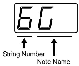
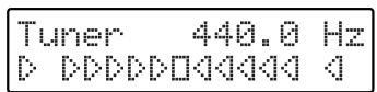
- Adjust the tuning.

For more detailed information and instructions for tuning, refer to "Adjusting the Guitar Tuning (Tuner Function)" (p. 18).
- After you have finished tuning, press any foot pedal or press [S1] or [S2] on the GK-2A.
You will return to Play mode.
Chapter 4 Five Basic Modes
The three main modes of the GR-33 allow you to:
- Select tones and perform "Play mode"
- Get effects such as wah or hold using the pedal on the base module "Pedal Effect mode"
-
Create and modify patches, and write them into memory "Patch Edit mode"
-
Establish settings for the entire GR-33 "System mode"
- Adjusting the tuning "Tuner mode"
How buttons, dials, and knobs work varies depending on the mode you are in.
Play Mode
In Play mode, the buttons and dials work as follows:
[BANK/PARAMETER] Button
Moves you forward and back through patch banks.
[PLAY]Button
Has no function in this mode.
[SYSTEM]Button
Switches to System mode (settings for the GR-33 itself).
[TUNER]Button
Switches to Tuner mode (p. 18).
[WRITE]Button
Writes the contents of a patch (p. 36).
[COMMON]Button
Switches to Patch Edit mode, COMMON (overall patch settings).
[TONE] Button
Switches to Patch Edit mode, TONE (sound-related patch settings).
[EFFECTS] Button
Switches to Patch Edit mode, EFFECTS (effect-related patch settings).
[STRING SELECT] Button
Has no function in this mode.
[OUTPUT SELECT] Button
Changes the output device selection (p. 19).
[PACK/VALUE] Dial
Moves forward and back through patches (p. 23).
- If the "DIAL FUNCTION" is set to "VALUE Only," this will be ignored.
Pedal 1-4
Switches patches (p. 22).
Expression Pedal
Changes the value of the selected parameter (p. 47).
GK-2A [S1]
While this is held down, pedal workings can be changed (p.
22, 29). (TUNER, GROUP , BANK , BANK )
GK-2A [S2]
Switches to Pedal Effect mode (p. 26).
External Bank Shift Pedal
For switching patch banks.
(This does the same thing as BANK and BANK ).
When "S1/S2 FUNCTION" is Set to "Patch Select"
When "S1/S2 FUNCTION" is set to "Patch Select," use the GK-2A's [S1] and [S2] buttons to move up and down through the patches. Operation of the following buttons will differ from normal Play mode as follows.
- Buttons and dials not listed here will function the same way as in normal Play mode.
Pedal 1-4
Function as in Pedal Effect mode (p. 31).
GK-2A [S1]
Advances through patches.
GK-2A [S2]
Goes back through patches.
External Bank Shift Pedal
Goes forward and back through patches.
HINT
When you want to check something by listening to patches played in order—or want to toggle between a pedal effect such as hold, and a patch—this is a convenient way to do so without having to switch modes. With PATCH INC/DEC BY S1/S2 selected, patch numbers are shown in the display, with “PdL” appearing about once every four seconds.
Pedal Effect Mode
In Pedal Effect mode, buttons and dials work as follows.
Additionally, you can change the nature of the available effects by pressing Pedals 1 to 4 in each patch. You can also change and re-record effects settings in User Patches A11 to d84.
[BANK/PARAMETER] Button
Goes forward and back through banks.
[PLAY] Button
Returns you to Play mode.
[SYSTEM]Button
Switches to System mode (settings for the GR-33 itself).
[TUNER] Button
Switches to Tuner mode (p. 18).
[WRITE]Button
Writes the contents of a patch (p. 36).
[COMMON]Button
Switches to Patch Edit mode, COMMON (overall patch settings).
[TONE] Button
Switches to Patch Edit mode, TONE (sound-related patch settings).
[EFFECTS] Button
Switches to Patch Edit mode, EFFECTS (effect-related patch settings).
[STRING SELECT] Button
Has no function in this mode.
[OUTPUT SELECT] Button
Changes the output device selection (p. 19).
[PACK/VALUE] Dial
Goes forward and back through patches (p. 23).
- If “DIAL FUNCTION” is set to “VALUE Only,” this will be ignored.
Pedal 1
WAH Adds effects such as a wah pedal-like sound or mechanical-sounding vibrato.
Pedal 2
P - GLIDE Adds pitch glide, an effect that creates wide, smooth changes in pitch.
Pedal 3
HOLD Causes synthesizer sounds to continue to play even after the guitar string has stopped vibrating.
Pedal 4
CTRL Turns the MULTI-FX BYPASS, the arpeggiator (p. 76) and harmonist (p. 80) on and off. Is also used as an auxiliary pedal for holding arpeggios (p. 76).
Expression Pedal
Changes the value of the selected parameter (p. 47).
GK-2A [S1] and [S2]
Press either of these to return to Play mode.
External Bank Shift Pedal (Bank Up)
This is used for the arpeggiator's Tap Tempo Teach function (p. 79). Also toggles between major and minor when using harmonist (p. 85).
External Bank Shift Pedal (Bank Down)
Returns sounds that have been changed with the wah function back to the way they sounded when the patch was first selected. (Returns to the original sound even after normal patch-switching procedures.)
Patch Edit Mode: What It Means, How It Works
In this mode, you can program patches.
Patch Edit mode is divided into three sections: COMMON, TONE, and EFFECTS.
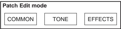
COMMON
This is where you name a Patch or set up pedal effects.
TONE
This is where you set up the tones that serve as the basis for synth sounds.
- EFFECTS
This is where you can set up reverb, chorus and multi-effects. Arpeggiator and Harmonist settings are also made here.
In Patch Edit mode, the buttons and dials work as follows:
[BANK/PARAMETER] Button
Use these buttons to select the parameter that you wish to adjust.
[PLAY]Button
Returns you to Play mode.
[SYSTEM]Button
Switches to System mode (settings for the GR-33 itself).
[TUNER] Button
Switches to Tuner mode (p. 18).
[WRITE]Button
Writes the contents of a patch (p. 36).
[COMMON]Button
Switches to Patch Edit mode, COMMON (overall patch settings).
- In the COMMON (concerned with patch settings) Patch Name Setting screen you can use this to switch between uppercase and lowercase characters (p. 38).
[TONE] Button
Switches to Patch Edit mode, TONE, (sound-related patch settings).
- In TONE (concerned with the sound of patches), pressing [TONE] will switch you between the 1ST and 2ND settings item.
[EFFECTS] Button
Switches to Patch Edit mode, EFFECTS (effect-related patch settings).
- If you are already viewing EFFECTS settings, pressing [EFFECTS] will turn the bypass function on/off (p. 75).
[STRING SELECT] Button
When adjusting a parameter that can be set independently for each string, use this button to select the string with which you want to work (p. 35).
- For parameters that are not set independently for each string, this button will have no effect.
[OUTPUT SELECT] Button
Changes the output device selection (p. 19).
[PACK/VALUE] Dial
Changes the value for the selected parameter.
Pedal 1-4
Used as auxiliary pedals in making any number of settings, and for confirming effects.
Expression Pedal
Used as auxiliary pedal in making any number of settings, and for confirming effects (p. 47).
GK-2A [S1] and [S2]
Changes the value for the selected parameter.
External Bank Shift Pedal
Changes the value for the selected parameter.

In Patch Edit mode, when you have modified even one parameter of the selected patch, the three-digit display will change. The decimal point of the lowest digit will light to indicate that the patch's settings have been modified.
Patch Edit mode
Period
If you wish to save the new settings, perform the Write operation (p. 36).
- If you change patches without performing the Write operation, your edits will be lost.
System Mode
In this mode you can make settings for the entire GR-33 — i.e., settings that do not change when you switch patches — such as input sensitivity and display brightness.
In System mode, the buttons and dials work as follows:
[BANK/PARAMETER] Button
Use these buttons to select the parameter that you wish to adjust.
[PLAY]Button
Returns you to Play mode.
[SYSTEM]Button
Has no function in this mode.
[TUNER] Button
Switches to Tuner mode (p. 18).
[WRITE]Button
Writes the contents of a patch. This is disabled during "BULK LOAD" (p. 37). It is used for initiating procedures and for confirmation in "BULK DUMP" and "FACTORY RESET" (p. 37, 16).
[COMMON]Button
Switches to Patch Edit mode, COMMON (overall patch settings).
[TONE] Button
Switches to Patch Edit mode, TONE (sound-related patch settings).
[EFFECTS] Button
Switches to Patch Edit mode, EFFECTS (effect-related patch settings).
[STRING SELECT] Button
Has no function in this mode.
[OUTPUT SELECT] Button
Changes the output device selection (p. 19).
[PACK/VALUE] Dial
Changes the value for the selected parameter.
Pedal 1-4
Has no function in this mode.
Expression Pedal
Changes the value of the selected parameter (p. 47).
GK-2A [S1] and [S2]
Changes the value for the selected parameter.
External Bank Shift Pedal
Changes the value for the selected parameter.
Procedures in Tuner Mode
In Tuner mode, the buttons and dials work as follows.
[BANK/PARAMETER] Button
Has no function in this mode.
[PLAY]Button
Returns you to Play mode.
[SYSTEM]Button
Switches to System mode (settings for the GR-33 itself).
[TUNER] Button
Has no function in this mode.
[WRITE]Button
Has no function in this mode.
[COMMON]Button
Switches to Patch Edit mode, COMMON (overall patch settings).
[TONE]Button
Switches to Patch Edit mode, TONE (sound-related patch settings).
[EFFECTS] Button
Switches to Patch Edit mode, EFFECTS (effect-related patch settings).
[STRING SELECT] Button
Has no function in this mode.
[OUTPUT SELECT] Button
Changes the output device selection (p. 19).
[PACK/VALUE] Dial
Changes the value for the "MASTER TUNE".
Pedal 1-4
Exits Tuner mode and returns you to Play mode.
Expression Pedal
Changes the value of the selected parameter (p. 47).
GK-2A [S1] and [S2]
Exits Tuner mode and returns you to Play mode.
External Bank Shift Pedal
Exits Tuner mode and returns you to Play mode.
Getting Into and Out of Each Mode
Here we will explain how to get into and out of each of the five modes: Play mode, Pedal Effect mode, Patch Edit mode, System mode and Tuner mode.
For modes other than Pedal Effect mode, you can press a single button on the GR-33 to enter the desired mode from any other mode. The following diagram shows the buttons corresponding to each mode, and the state of the three-digit display for each mode.
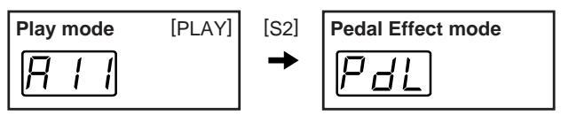
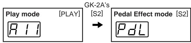
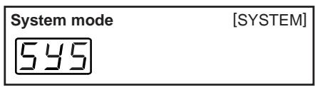
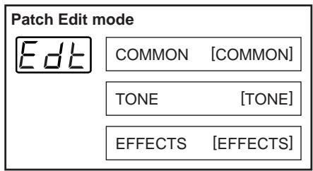

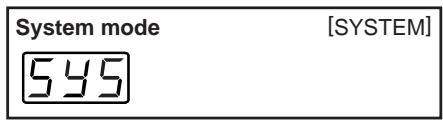
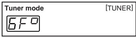
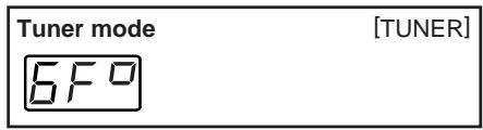
- Pedal Effect mode can be entered only from Play mode.
- If "S1/S2 FUNCTION" is not set to "Normal," it will not be possible to enter Pedal Effect mode.
Chapter 5 Setting/Changing Sounds (Patches)
Details of Putting a Patch Together
Every patch is constructed as shown in the following figure.
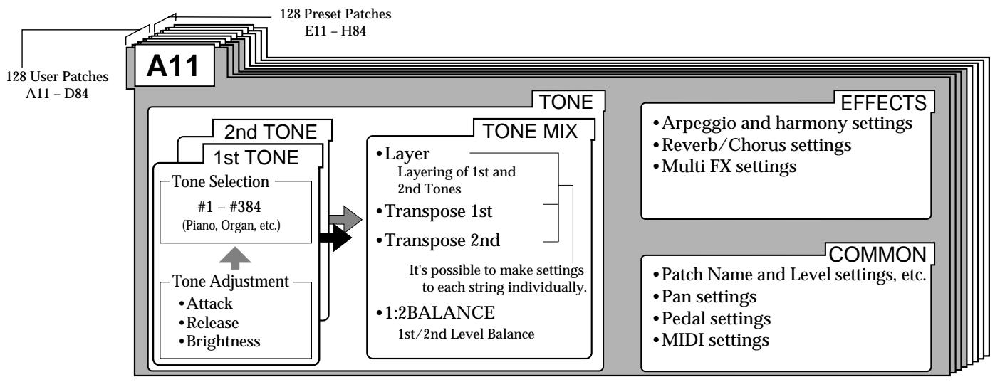
What is a "Tone"?
As shown in the above figure, you can select any two of the 384 built-in tones—the raw material for synth sounds—and use them in a patch.
The two tones in a patch are called the "1st tone" and the "2nd tone."
You can assign the selected tones separately to individual strings, and then layer them (p. 51). You can also adjust parameters such as attack (p. 49), release (p. 50), brightness (p. 50), and transpose (p. 51). In addition, you can also independently select a transposition (TRANSPOSE) for each string.
In addition to tone selections, tone settings can be saved in patches.
Recording and Settings of Each Patch
Besides patch tone-selection and string assignments—as well as tone settings—you can set and store the following items in a patch, as well as other items.
- Patch name (p. 38)
- How effects are applied (p. 53)
- Arpeggiator patterns and related settings (p. 76)
- Harmonist settings (p. 80)
- What happens when you step on a pedal (p. 43)
- Program numbers sent to external MIDI devices (p. 88)
- External sound generator transpositions (p. 51)
For more information about these settings, please consult the reference pages listed above for each item.
Making separate settings for each string (STRING SELECT)
Three of the TONE parameters—"LAYER," "1ST TRANSPOSE," and "2ND TRANSPOSE—and the four COMMON parameters—"MIDI [PC]," "MIDI [CC0]," "MIDI [CC32]," and "MIDI [TRANSPOSE]"—can be set separately for each string using the [STRING SELECT] button.
When you press [STRING SELECT], the three-digit display will indicate the selected string as follows.
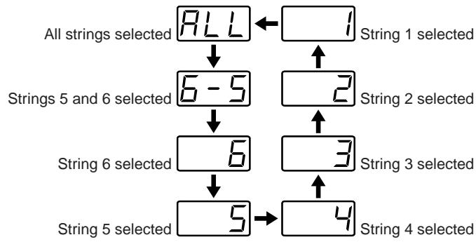
To set each string independently, press the [STRING SELECT] button to select the desired string, and then turn the [VALUE] dial to change the currently selected parameter's setting. For example, if you use the [STRING SELECT] button to select "5," and then turn the [VALUE] dial, the currently selected parameter's setting will change only for String 5. You can continue and adjust the settings for the other strings using the same method.
- If you use the [STRING SELECT] button to select "ALL" or "6-5," the parameter's value may blink, signifying that the settings for the selected strings are different from one another. If you turn the [VALUE] dial to select a value, the value will be applied to each selected string: to all strings if "ALL" is displayed, or to Strings 5 and 6 if "6-5" is displayed.
The Relationship Between Arpeggiator/ Harmonist and Patches
When you are playing, you can use the arpeggiator or the harmonist. For each patch, you can select one of these functions (p. 78, 82) and also determine whether or not it will be active (p. 77, 81) when the patch is selected.
Likewise, you can select arpeggio patterns—the sequence of strings that the arpeggiator function creates and plays—for each patch individually from among the available 50 patterns.

For more details about making these settings, refer to "Selecting Arpeggio Patterns (ARP PATTERN)" (p. 79).
Saving Patches
Generally, you create and modify patches by using [PARAMETER] to select parameters in Patch Edit mode, and turning [VALUE] to select the desired values.
It is important to remember that if you simply switch to another patch, the changes you have made will be lost, and the edited patch will revert to its original state. (The lowest decimal point in the three-digital display lights (p. 32) to warn you of this.) To save any changes you have made, use the following steps to perform the Patch Write operation before changing to another patch.
Performing a Patch Write
- Press [WRITE]—you enter Write mode, and a screen like the one shown below appears.
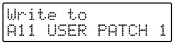
- Turn [VALUE] to choose the patch location to which you want to save the patch.
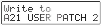
- After you have specified the writing destination, press [WRITE].
The following confirmation screen appears.
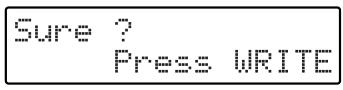
- After making sure that you want to complete this operation—and that you are ready to write over the patch currently in the selected destination location—press [WRITE] once again.
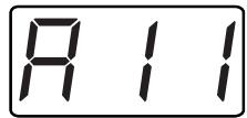
Now writing.
"Now Writing..." appears in the display. In a moment, the GR-33 automatically returns to Play mode, completing the writing procedure.
- To cancel the operation, press [PLAY].
Once you have performed these steps, the changes you have made to the patch will be recalled when that patch is selected, even if you switch to another patch or turn the power off.
- If you write without designating a location where the patch is to be saved, you will overwrite the original version of the patch, and that version of the patch will be discarded.
- As Patch Groups E through H are read-only, you cannot overwrite them by saving a patch to their locations.
Cautions When Saving
With Patch Write, the patch is written the way it actually sounds at the time you write it, and this includes whether the Arpeggiator or Harmonist functions are turned on or off. However, temporary tone changes made with the base module pedals, such as wah and pitch glide, or those from external expression pedals, will not be saved. This also applies to the temporary switching off of internal effects using the effect bypass function (p. 75).
- You do not have to manually save the System mode parameters that apply to the entire GR-33. Changes made to these settings are saved automatically, and are stored even after the power is turned off.
Saving Patches From the GR-33 to Sequencers or Other MIDI Devices (Bulk Dump)
Settings for all user patches—as well as all system settings—can be transferred in and out of the GR-33 using MIDI. You can also save patches externally to equipment that can record MIDI data. For this kind of operation, the GR-33 uses MIDI messages called "System Exclusive messages," or "SysEx" messages. Each System Exclusive message can be interpreted only by the device for which it is intended.
SysEx data sent from the GR-33, data read from a floppy disk, or data entered by other means can be stored in a MIDI sequencer using the sequencer's realtime recording or bulk librarian function. You can also send/receive SysEx data directly from one GR-33 to another by connecting the two via MIDI.
Sending System Settings or Patch Data to an External MIDI Device
- Turn off the power to the GR-33.
- Connect the GR-33's MIDI OUT to the MIDI IN connector on the external MIDI device.
- Turn on the power of the GR-33.
- Press [SYSTEM] to enter System mode.
- Press [PARAMETER] to select "BULK DUMP."

BULK DUMP
A11
- Turn [VALUE] to select the type of data you wish to transmit.
All: All user patches and system settings
System: System settings
User Patch: All user patches (128 patches)
Patch Group A: The 32 patches A11 to A84
Patch Group B: The 32 patches B11 to B84
Patch Group C: The 32 patches C11 to C84
Patch Group D: The 32 patches D11 to D84
Patch A11: Patch A11 only
Patch A12: Patch A12 only
:
Patch D84: Patch D84 only
- Put the external MIDI device in record mode. For example, start a MIDI sequencer's realtime recording.
- Press [WRITE]. The selected data is transmitted from the GR-33 to the external device. While data is being transmitted, the GR-33 display shows "Now Sending...".
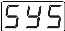
Now Sending...
- Sending is complete when the GR-33's previous display returns. If a sequencer is on the receiving end of a transfer, stop recording at this point.
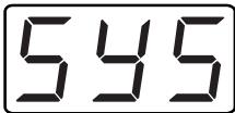
BULK DUMP
A11
- Press [PLAY] to return to Play mode.
Receiving previously saved system or patch data (Bulk Load)
Here's how you can receive system or patch data from an external device capable of recording MIDI data, or from another GR-33.
- Exclusive messages can be received only in the Bulk Load screen.
Receiving system settings or patch data from an external MIDI device
- Turn off the power to the GR-33.
- Connect the external MIDI device MIDI OUT to the MIDI IN connector on the GR-33.
- Turn on the power of the GR-33.
- Press [SYSTEM] to enter System mode.
- Press [PARAMETER] to select "BULK LOAD."
BULK LOAD
waiting...
- Transmit the data from the external device.
BULK LOAD
Receiving.
When reception is finished, the previous display will reappear.
BULK LOAD
waiting...
Chapter 5 Setting/Changing Sounds (Patches)
-
Press [PLAY] to return to Play mode.
-
If you send data for a single patch to the GR-33, you will need to perform the Patch Write operation (p. 36) on the GR-33 to store the patch in a patch memory location. When writing the received patch, you can specify the desired destination, so you are not forced to overwrite the same-numbered patch if it is one you wish to keep.
-
Except for the receiving of A11 through D84 as single patches, no special conditions apply for storing patch or system parameter data received via SysEx.
- Since data can be lost should unexpected events occur, we strongly recommend regularly using the Bulk Dump feature to back up your GR-33 data.
Naming the Patches (PATCH NAME)
You can assign a name of up to twelve characters to each patch. Assign a name that will help you remember the sound, or the song for which the patch is intended.
■Assigning a Name to a Patch
- Select the patch whose name you want to change, and press [COMMON] to enter Patch Edit mode.
- Press [PARAMETER] to select "PATCH NAME."

PATCH NAME USEB PATCH 1

-
Use [PARAMETER] to move the cursor to the character you wish to modify.
-
Turn [VALUE] to select the desired character, number or symbol.
-
You can press [COMMON] to switch between uppercase and lowercase characters.
-
Repeat Steps 3 and 4 to complete the name.
-
Press [WRITE] to perform the Patch Write operation (p. 36).
-
After performing the Patch Write operation, you will automatically return to Play mode.
- If you don't wish to save the Patch's new name, press [PLAY] to return to Play mode instead of pressing [WRITE].
Setting the Volume Level of Each Patch (PATCH LEVEL)
For things like switching between multiple patches while playing, having the volume of backing patches set lower than the volume of solo patches is a convenient feature. You can make these kinds of volume settings by recording the patch level (PATCH LEVEL) of each patch.
Determining and Recording Patch Volumes
- Select the patch whose volume you want to change, and press [COMMON] to enter Patch Edit mode.
- Press [PARAMETER] to select "PATCH LEVEL."
PATCH LEVEL
80
- Use [VALUE] to change the value.
The value changes within a range of 0 to 100. A setting of "0" silences to patch, and "100" sets it to maximum volume.
-
Press [WRITE] to perform the Patch Write operation (p. 36).
-
After performing the Patch Write operation, you will automatically return to Play mode.
- If you don't want to save the Patch, press [PLAY] to return to Play mode.
-
Even with PATCH LEVEL values the same, volume levels may change according to other settings. In the example below, the level has been set high. If PATCH LEVEL is then set to a low level, the balance of another patch is used. (The combination of the settings shown below may cause excessively high volume levels, so be careful not to allow this to result in damage to amps and speakers.)
-
When both the first and second tones are present.
- When the Reverb send level or Chorus send level is set to a high level.
-
When a high volume level is a characteristic of the tone itself.
-
When the brightness setting value is high.
- When wah effects are applied.
Changing the Feel of a Performance (PLAY FEEL)
Guitars differ from keyboards and other instruments in that the part of the instrument that actually vibrates (i.e. the string) is touched directly, allowing subtle control of the power with which it is played. To let the guitar synthesizer make maximum use of this feature, it is necessary to set the "playing response."
This selection is made with "PLAY FEEL" in the COMMON setting of Patch Edit mode. For example, by changing the Play Feel options like "finger picking" or "normal picking," you can get very natural-sounding expression of how much power is in the playing.
Changing and Recording Play Feel
- Select the patch whose PLAY FEEL you want to change, and press [COMMON] to enter Patch Edit mode.
- Press [PARAMETER] to select "PLAY FEEL."
PLAYFEEL Normal
-
Use [VALUE] to change the value.
-
For a detailed explanation, see the subsequent section, "The PLAY FEEL settings and their effects."
-
Press [WRITE] to perform the Patch Write operation (p. 36).
-
After performing the Patch Write operation, you will automatically return to Play mode.
- If you don't want to save the Patch, press [PLAY] to return to Play mode.
The PLAY FEEL settings and their effects
There are eight settings ("Normal," "Finger," "Hard," "Soft," "Tapping," "No Dynamics," "Envelope1," "Envelope2"), and eight settings that add the Accel function to each of these ("Accl Normal," "Accl Finger," "Accl Hard," "Accl Soft," "Accl Tapping," "Accl No Dynamics," "Accl Envelope1," "Accl Envelope2").
These meanings are as follows:
Normal:
General picking, thus the standard setting for play.
Finger (finger picking):
The setting for when you want to perform with the feeling finger picking provides. Sensitivity is a little higher than with normal picking.
Hard (hard picking):
This setting is for those who pick rather hard, and the sensitivity is a little lower than with normal picking.
- When there is a problem with the guitar's arrangement, and the only places GK-2A's divided pickup can be installed are too close to the strings, you may be able to improve the behavior with the settings in each patch.
Soft (soft picking):
For picking that is a little weaker. Sensitivity is a little higher than with normal picking.
Tapping (tapping play):
When making use of many kinds of picking techniques, such as tapping play (or "right-hand play"), pulling-off, or hammering-on, this setting provides very stable sound expression. The range of power that can be expressed is a bit narrow.
No Dynamics (no dynamics):
With this setting, no matter how hard or softly you play, you get uniform volume and tone. Use this setting with tones like Synth Lead or Organ when you want to transmit a feeling without expression.
Envelope1 (envelope follow type1):
This is for setting how much the synthesizer volume influences the amplitude of the strings.

For details, see the subsequent section, "Following the Guitar Sound Shape (Envelope Follow)."
Envelope2 (envelope follow type2):
This is for setting how much the overall tone (brightness) is influenced by the amplitude of the strings.

For details, see the subsequent section, "Following the Guitar Sound Shape (Envelope Follow)."
The eight types "Accl Normal," "Accl Finger," "Accl Hard," "Accl Soft," "Accl Tapping," "Accl No Dynamics," "Accl Envelope1," and "Accl Envelope2" add the Accel function to the previously listed eight types. Notes will sound more quickly than the first eight types.

For details, refer to "Increasing the Speed of Expression (Acceleration)" (p. 40).
- Picking strength and power range vary from player to player. The names of these settings ("normal," "soft," "hard," and so on) are for easy reference only, so you are encouraged to actually switch through the settings, and when you find ones that you feel are easy to play, that you feel have characteristics of instruments you'd like to play, paying no special attention to their names, go ahead and select those settings.
Following the Guitar Sound Shape (Envelope Follow)
When you select the "Envelope1" and "Envelope2" settings in the above PLAY FEEL section, the envelope follow function comes on, giving you that effect.
In this condition, changes in the strings' amplitude (changes due to picking, or from how the sound decays) are influenced by the volume or tone of the synthesizer sounds. You can get the following types of effects.
Envelope1 (envelope follow type1):
Here, the synthesizer volume influences the amplitude of the strings. You can get a natural feel when using decay tones (from guitars, electronic pianos, and so forth), so do try this setting. (Change in the synth sound's volume is a little more compressed, a bit more restrained than that of the guitar.
Envelope2 (envelope follow type2):
This is for setting how much the overall tone (brightness) is influenced by the amplitude of the strings. Along with the decay, which depends on the picking strength and time elapsed, this setting changes the sound's brightness (regulation of muffled sound) dynamically. Especially with Synth Lead tones, you can get that tone's characteristic effect. The following procedure, combined with the wah auto wah function, you can get a touch wah effect with extremely smooth response.
Getting a Touch Wah Effect with the PLAY FEEL "Envelope2" Setting
- Let's select a synth lead patch.
- Press [COMMON], use [PARAMETER] to move the cursor to "PLAY FEEL," and use [VALUE] to Select "Envelope2."
- Press [PARAMETER] to select "WAH TYPE."
- Use [VALUE] to select "AutoWah1-5."

For more details on WAH TYPE, refer to "Selecting Wah Types (WAH TYPE)" (p. 43).
-
Play the guitar to confirm that the wah effect is responding to the strength of the picking.
-
To save the settings in patches, press [WRITE] to perform the Patch Write operation (p. 36).
- When "Envelope1" or "Envelope2" is selected for PLAY FEEL, the envelope follow data will be sent from MIDI OUT as controller no. 18 (general purpose controller 3).
Increasing the Speed of Expression (Acceleration)
When you are making selections in PLAY FEEL (p. 39), when items containing "Accl" in the lower right corner of the display are selected, the GR-33's "Acceleration Function" is turned on. When put in this mode, the average speed from picking to sound is higher than usual.
However, when this function is being used, the effect of internal processing of string noise abatement is weakened. This means that for some tones, you may hear noise or pitch change when you pluck the string. If you use the Accelerator function, please confirm when you're creating a sound that there is no bothersome noise in the tone you are using.
Changing Sound Placement (PAN)
You can pan each of a patch's two tones to its own stereo location. For example, you can pan one tone to the far left in the stereo field, and the other to the far right.
You can also create complex stereo movement using a variety of pre-programmed stereo effects. This is done using the COMMON "PAN MODE" and "PAN" settings in Patch Edit mode.
Setting and Saving Sound Placement
- Select the patch whose pan position you want to set, and press [COMMON] to enter Patch Edit mode.
- Press [PARAMETER] to select "PAN MODE."
PAN MODE
Normal
-
Use [VALUE] to select the desired pan mode.
-
For more details, see the subsequent section, "Available value for PAN, and their effects."
-
If you are not using Normal or Cross Tones, proceed to step 6.
-
Press [PARAMETER] to select "PAN."
FAN
56
- Turn [VALUE] to select the desired value.
-
Press [WRITE] to perform the Patch Write operation (p. 36).
-
After performing the Patch Write operation, you will automatically return to Play mode.
- If you don't want to save the Patch, press [PLAY] to return to Play mode.
Available values for PAN, and their effects
Normal:
With a setting of 0, all sounds will be panned to the center. Changing the value within the range from -50 through 50 will cause the panning to change correspondingly. Both the 1st and the 2nd tone will be panned to the far right with a setting of 50, or to the far left with a setting of -50.
Cross Tones:
With the setting at "0," the selected tone is placed in the center of the stereo field. By changing the values across a range of -50 to 50, the tone's position shifts left or right: when a tone is set to 50, it is panned all the way to the right; setting it to -50 pans it all the way to the left. Therefore, by programming a patch with one tone set to 50 and the other to -50, you can create a rich, widespread stereo sound.
1-6, 6-1:
With this setting, each string is panned separately. When you select 1-6, the strings' sounds are placed in sequence from the left: String 1, String 2, all the way up to String 6. Conversely, with 6-1, the opposite positioning is used, i.e. String 6, String 5, all the way down to String 1.
Odd-Even, Even-Odd (Odd, Even):
This setting separates odd- and even-numbered strings, and places them left and right. With Odd-Even, the odd-numbered strings—1, 3, and 5—are panned left, and the even-numbered strings—2, 4, and 6—panned right. “Even-Odd” will produce the same effect as if “Odd-Even” were exchanged left to right.
Random Both, Random 1st, Random 2nd:
The stereo placement of the 1st and 2nd tones changes randomly. "Random 1st" and "Random 2nd" cause only the corresponding tone to move around randomly—the other tone is placed in the center.
Alternate Both, Alternate 1st, Alternate 2nd:
The perceived location of the 1st and 2nd tones assigned to each string is panned alternately to the left and right each time a tone is sounded. For patches having only one tone playing, the tone moves back and forth repeatedly. With a patch using both tones—but with the 1st tone to the right and the 2nd tone to the left—a special stereo effect is created that differs from what you get with the Random setting.
"Alternate 1st" and "Alternate 2nd" causes only the corresponding tone to jump back and forth—the other tone is placed in the center.
- Pan settings have no effect on the internal reverb and chorus.
- You can hear the selected panning effect only through equipment that can produce stereo sound—and is connected to the GR-33's MIX OUT using two cables—or when using stereo headphones.
- The PAN setting made here is ignored if you have a monaural type of MULTI-FX selected.
Dividing Continuous Pitch Changes into Semitones (CHROMATIC)
The GR-33 faithfully reproduces the slight pitch changes and in-between notes you get from fingering your guitar's strings.
However, should the need arise, you can also limit this subtle pitch response to semitone changes only. This is called the Chromatic function, and is turned on and off using the COMMON "CHROMATIC" setting in Patch Edit mode.
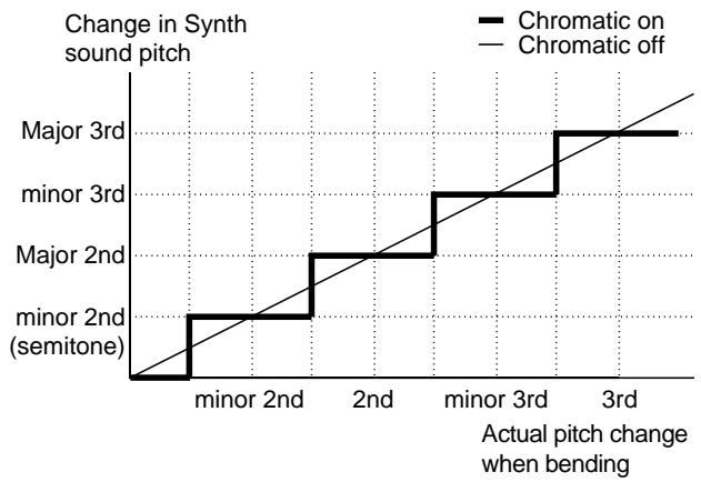
Turning the Chromatic Function On and Off and Saving It to Patches
- Select the patch you want to change, and press [COMMON] to go into Patch Edit mode.
- Press [PARAMETER] to select "CHROMATIC."
CHROMATIC
Off
-
Turn [VALUE] to select the desired setting.
-
For a detailed explanation, see the subsequent section, "Chromatic Settings and Available Effects."
-
Press [WRITE] to perform the Patch Write operation (p. 36).
-
After performing the Patch Write operation, you will automatically return to Play mode.
- If you don't want to save the Patch, press [PLAY] to return to Play mode.
Chromatic Settings and Available Effects
Off (Chromatic Off):
For guitar bending and vibrato, this setting allows you to make synth sounds faithfully reproduce subtle played pitch changes of less than a semitone.
When you select any setting other than Off, pitch changes are limited to semitones.
Type1:
If the pitch is changed smoothly, for example by bending the guitar string, the pitch will change in semitone steps. When the pitch changes, the currently-heard sound will not stop; it will merely change in pitch. There is no separate attack sound when the pitch changes—this is a change similar to the one you hear with the slurred playing of a recorder.
Type2:
If the pitch is changed smoothly, the pitch will change in semitone steps. When the pitch changes, the sound for the new pitch will be started over, or "retriggered." Thus, whenever the pitch changes, you will hear a new attack. If the retrigger occurs as a string's vibration is trailing off (decaying), the retriggered note will play at an appropriately reduced volume.
Type3:
This is basically the same effect as "Type2," except that the retriggered sound level is not influenced by the current state of the string's vibration.
When You Want to Make a Chord Resonate Beautifully
Due to subtle pitch changes resulting from the way each string is pressed, with patches using long notes, chords may end up sounding muddy. If this occurs, turn Chromatic on so that only pure semitones are heard, thus producing a beautifully in-tune chord. If you select "Type1," pitch differences will be barely audible, creating a natural-sounding resonance.
When You Want to Reproduce Piano-like Pitch Changes
In patches that emulate instruments which do not use pitch changes smaller than a semitone, Chromatic allows you to more easily imitate the instrument's sound. In such cases, when "Type2" or "Type3" is selected, the attack is reproduced with each pitch change. (Depending on the tone or melody, there may be times when "Type1" or Off' yield a better effect, so select the setting you like best.)
Selecting Wah Types (WAH TYPE)
There are 35 types, in seven groups, of wah effects you can get by stepping on and releasing pedal 1 in Pedal Effect mode, with differing ranges of tone change and different speeds, and along with one type of modulation (vibrato), there are a total of 36 variations of wah pedal effects.
Selecting Wah (or Modulation) Type
- Select the patch whose effect type you want to change, and press [COMMON] to go into Patch Edit mode.
- Press [PARAMETER] to select "WAH TYPE."
WAH TYPE
wah1
-
Use [VALUE] to change the setting.
-
For a detailed explanation, see the subsequent section, "Wah Pedal Variations that can be selected in WAH TYPE."
-
When making settings, play the guitar with pressing pedal 1 to try the effect.
-
Press [WRITE] to perform the Patch Write operation (p. 36).
-
After performing the Patch Write operation, you will automatically return to Play mode.
- If you don't want to save the Patch, press [PLAY] to return to Play mode.
Wah Pedal Variations that can be selected in WAH TYPE
The digit (1-5) at the end of the displayed type name indicates the speed at which the tone will change. When you step on and release the pedal, the numbers show, with "1" indicating the fastest tone change, and as these numbers get larger, the speed decreases.
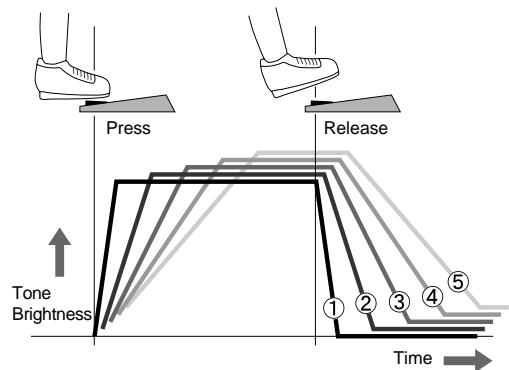
Examples of Wah1 to Wah5, Brightness1 to Brightness5, etc. (Changes over time)
Wah1-5:
This adds an effect that resembles a guitar wah pedal to the synthesizer sound. With this unique effect added to the sound, stepping on the pedal gives the tone a brighter "wah" sound, and when the pedal is released, the sound becomes darker, with an "oww" sound. By repeatedly stepping on and releasing the pedal, you can get an effect that sounds like "wah wah wah."
AutoWah1-5:
This is basically the same effect as the wah pedal (Wah 1-5), but rather than being applied with the pedal, with this novel method, the effect is automatically applied each time the guitar is picked. In this situation, the pedal still works to add affect, so you can use both of these options together. When combined with the Play Feel setting "Envelope2" on tones like Synth Bass, you can get a smooth "touch wah" effect.

For details on setting the "touch wah" effect, refer to "Following the Guitar Sound Shape (Envelope Follow)" (p. 40).
Brightness1-5:
This controls only the brightness of the sound, without adding the characteristic sound of the wah itself. In all other actions, it is absolutely identical to Wah 1 to 5.
NarrowWah1-5:
This compresses the tone difference from stepping on and releasing the pedal to half the range of the normal wah (Wah 1 to 5). In all other actions, it is absolutely identical to Wah 1 to 5.
R.Wah1-5 (Reverse Wah 1-5):
This reverses the tones from stepping on and releasing the pedal in normal wah (Wah 1 to 5) (i.e. step dark sound, release bright).
R.Brightness1-5 (Reverse Brightness 1-5):
This reverses the tones from stepping on and releasing the pedal in the brightness setting (Brightness 1 to 5) (i.e. step dark sound, release bright).
R.NarrowWah1-5 (Reverse Narrow Wah 1-5):
This reverses the tones from stepping on and releasing the pedal in Narrow (NarrowWah 1 to 5) (i.e. step dark sound, release bright).
Modulation:
When you select this setting, as you step on the pedal, then rather than a wah-type effect, a deep vibrato (wavering pitch) effect is added. Differing from the mood created by playing finger vibrato on the guitar, it gives a mechanical, synthesizer-sounding vibrato.
The speed and depth of the vibrato you get with this function is predetermined for each tone.
Chapter 5 Setting/Changing Sounds (Patches)
-
If you use wah once, the sound from a patch with a muffled sound may continue, or some other kind of peculiarity may change, even after releasing the wah pedal. If this happens, switch to another patch, and then call up the desired patch again to return to the original sound.
-
When the wah is "closed," that is, the sound of the wah effect is too dark (or muffled), switch "WAH TYPE" to either "NarrowWah 1 to 5" or "R.NarrowWah 1 to 5," and adjust this by changing the "BRIGHTNESS" (p. 50) setting.
- The application of wah-type effects varies with the selected tone.
Selecting Pitch Glide Type (GLIDE TYPE)
With the Pitch Glide you get by pressing pedal 2 in Pedal Effect mode, there are seven different ways to have the pitch change width and speed, with both up and down patterns prepared.
Selecting Pitch Glide Type
- Select the patch whose effect type you want to change, and press [COMMON] to go into Patch Edit mode.
- Press [PARAMETER] to select "GLIDE TYPE."
GLIDE TYPE
Down?
-
Use [VALUE] to change the setting.
-
For a detailed explanation, see the subsequent section, "Variations that can be selected for GLIDE TYPE."
-
When making settings, play the guitar with pressing pedal 2 to try the effect.
-
Press [WRITE] to perform the Patch Write operation (p. 36).
-
After performing the Patch Write operation, you will automatically return to Play mode.
- If you don't want to save the Patch, press [PLAY] to return to Play mode.
Variations that can be selected for GLIDE TYPE
Below are the seven types of effect you can select from.
These have been set as both "pitch up" and "pitch down," giving you four teen effects to choose from. For example,
"Up Type 5" is indicated by "Up5" and "Down Type 3" by "Down3."
Up1 (Down1):
When the pedal is pressed, the pitch changes continuously up to a perfect fourth. Release the pedal to return to the original pitch.
Up2 (Down2):
Just as in Up1 (Down1), the pitch change is a perfect fourth, but the time it takes to make the change is a little longer.
Up3 (Down3):
When the pedal is pressed, the pitch changes continuously up to a perfect fifth. Release the pedal to return to the original pitch.
Up4 (Down4):
When the pedal is pressed, the pitch changes continuously by one octave. Release the pedal to return to the original pitch.
Up5 (Down5):
The pitch change here is an octave, but the time it takes to make the change is a little longer. (The return time is the same as in Up4 (Down4)).
Up6 (Down6):
The pitch change in this effect is an octave, but both the time for the pitch to change and the return time are longer.
Up7 (Down7):
Press the pedal for an instant one-octave rise (or drop).
- The pitch change width when "Pitch" or "Tempo&Pitch" is assigned to an external expression pedal (p. 47) also corresponds to the selection in GLIDE TYPE (fourth, fifth, or one octave).
- With the Pitch Glide function, depending on the tone and range, the width of the pitch's rise may be limited.
Selecting Hold Type (HOLD TYPE)
With the Hold function on pedal 3 in Pedal Effect mode, for the qualities such as the sustaining of a tone's sounding, there are fifteen ready-made variations that can be selected according to the particular purpose, and saved to patches.
Selecting Hold Type
- Select the patch whose effect type you want to change, and press [COMMON] to go into Patch Edit mode.
- Press [PARAMETER] to select "HOLD TYPE."
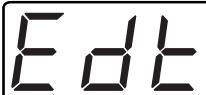
HOLD TYPE Damper A11
-
Use [VALUE] to change the setting.
-
For a detailed explanation, see the subsequent section, "Variations that can be selected for HOLD TYPE."
-
When making settings, play the guitar while pressing pedal 3 to try the effect.
-
Press [WRITE] to perform the Patch Write operation (p. 36).
-
After performing the Patch Write operation, you will automatically return to Play mode.
- If you don't want to save the Patch, press [PLAY] to return to Play mode.
Variations that can be selected for HOLD TYPE
There are three types of hold effects you can select: damper; sostenuto; and string.
Damper Hold/Damper:
When you play the guitar while holding down the pedal, the sound is sustained while playing continues, an effect like that of a piano's damper pedal.
When you hold the pedal down, you can play chords without letting the sound from all the notes played die away. However, even during Hold you cannot play the same string more than once in an attempt to layer the synth sounds coming from the same string.
- The guitar recognizes the pitch only as long as the string continues to vibrate, and this is reflected in the pitch of the synth sound at all times.
Sostenuto Hold/Sostenuto:
Only the synth sounds that are sounding at the moment the pedal is pressed will be held as long as the pedal remains pressed.
From the moment you go into Hold, to when the pedal is released, the sustained synth sound remains unaffected, even when you continue to play the guitar. Thus, it is convenient for things like holding a synth sound chord and layering it with a guitar melody, or for when you want to make the same effect using the first and second tones. (Strictly speaking, it isn't but) the Hold effect is very much like the sostenuto pedal of an electronic piano.
String Hold/String:
You can apply this hold effect to the strings of your choice. As with "Sostenuto" above, the synth sound being played at the instant you press the pedal is sustained, and continues even if the string stops vibrating.
What's different is that even without releasing the pedal, the synth sound from strings not being held can still be controlled with the guitar. This makes it possible to do things like hold the synth sound on strings 5 and 6, and play a melody over that with synth sound played by strings 1 through 4.
Releasing the pedal stops the held sound.
Here are the fifteen types, which can be selected by using [VALUE], as they actually appear (when Arpeggiator is off).
Damper All:
This damper hold works on all internal and external MIDI sound generators.
Damper 1st:
This damper hold works only on the first internal sound generator.
Damper 2nd:
This damper hold works only on the second internal sound generator.
Damper 1&2:
This damper hold works on both the first and second internal sound generators. (Not effective on external sound generators.)
Damper Ext:
This damper hold works only on external MIDI sound generators.
Damper Ext&1:
This damper hold works on the first internal sound generator and on external MIDI sound generators.
Damper Ext&2:
This damper hold works on the second internal sound generator and on external MIDI sound generators.
Chapter 5 Setting/Changing Sounds (Patches)
Sostenuto All:
This sostenuto hold works on all internal and external MIDI sound generators.
Sostenuto 1st:
This sostenuto hold works only on the first internal sound generator.
Sostenuto 2nd:
This sostenuto hold works only on the second internal sound generator.
Sostenuto 1&2:
This sostenuto hold works on both the first and second internal sound generators. (Not effective on external sound generators.)
Sostenuto Ext:
This sostenuto hold works only on external MIDI sound generators.
Sostenuto Ext&1:
This sostenuto hold works on the first internal sound generator and on external MIDI sound generators.
Sostenuto Ext&2:
This sostenuto hold works on the second internal sound generator and on external MIDI sound generators.
String:
This string hold works on all internal and external MIDI sound generators.
- When Arpeggiator is on, the fifteen choices shown above are reduced to four: "Damper"; "Sostenuto"; "Latch TypeA"; and "Latch TypeB." At such times, the Hold function is effective only on arpeggios, and you can use it in special ways such as changing the arpeggios to chords without the rhythm of the arpeggios being stopped.

For details, refer to "Effective Use of the Hold Function During Arpeggios" (p. 76).
Using the CTRL Pedal
Pedal 4 (the CTRL pedal) in Pedal Effect mode can be used as an on/off switch for either MULTI-FX or Arpeggiator/ Harmonist. This setting can be saved in patches.
- Specifying the function of the CTRL pedal
- Select the patch whose Pedal 4 function you wish to set, and press [COMMON] to enter Patch Edit mode.
- Press [PARAMETER] to select "CTRL PEDAL."
- Turn [VALUE] to select the desired setting.
HAR/ARP Control:
Each time you press the pedal, Arpeggiator/Harmonist will be switched on/off.
Multi-FX Bypass:
Each time you press the pedal, the MULTI-FX Bypass will be switched on/off.
-
Even by depressing the CTRL pedal, you won't be able to change the multi-effect to anything other than "Off" if the "MULTI-FX SW" (p. 53) parameter has been stored as being "Off" within the patch.
-
Press [WRITE] to perform the Patch Write operation (p. 36).
-
After performing the Patch Write operation, you will automatically return to Play mode.
- If you don't want to save the Patch, press [PLAY] to return to Play mode.
- You may hear a noise when MULTI-FX BYPASS is switched on/off, but this does not indicate a malfunction.
Using the Expression Pedal
By using the expression pedal (EXP pedal) attached to the GR-33, you can add various effects to synth sounds. You can choose from among eighteen effects that can be controlled with the EXP pedal, including pitch, volume, arpeggiator tempo and the like.
You can also use the EXP pedal for sending MIDI data for the selected control change number. All of the above settings can be saved in patches.
To Add Effects
Use the EXP pedal to immediately apply a designated effect to the patch.
- When you have used the EXP pedal to add an effect to a patch, and you switch to another patch, the pedal effect will be canceled regardless of the pedal's position. The newly selected patch will play as programmed—the EXP pedal's position will begin to affect the sound the first time it is moved after the sound has been selected.
However, if both of the patches being switched between have "Volume," "Volume 1st," or "Volume 2nd" assigned to them, the prevailing volume level, as determined by the position of the EXP pedal before the patch change, will be carried over to the patch being switched to.
To Switch Effects (EXP PEDAL)
Selecting the Expression Pedal Effect Type
- Select the patch whose effect type you want to change, and press [COMMON] to go into Patch Edit mode.
- Press [PARAMETER] to select "EXP PEDAL."
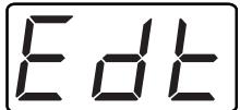
EXP PEDAL Volume
-
Turn [VALUE] to select the desired setting.
-
For more details, see the subsequent section, "Variations that can be selected for EXP PEDAL."
-
When setting up effects, play the guitar while pressing Pedal 1 to try out the effect.
-
Press [WRITE] to perform the Patch Write operation (p. 36).
-
After performing the Patch Write operation, you will automatically return to Play mode.
- If you don't want to save the Patch, press [PLAY] to return to Play mode.
Variations that can be selected for EXP PEDAL
Volume:
Adjusts the volume level, from zero up to the level set with the GK-2A's volume knob.
Volume 1st (1st Tone Volume):
Controls the volume of the 1st tone only. In patches using both tones, you get the effect of the 1st tone being added to the 2nd.
Volume 2nd (2nd Tone Volume:
Controls the volume of the 2nd tone only. In patches using both tones, you get the effect of the 2nd tone being added to the 1st.
Balance:
Changes the volume balance between the 1st and 2nd tones. With the pedal all the way up (back), only the 1st tone is heard, and when pressed completely down (forward), only the 2nd tone plays.
Tone Param (tone parameter):
Modifies the parameters that are specific to the selected tone. The change will depend on the selected tone.
Multi-FX Param (multi-effect parameter):
Modifies the parameters that are specific to the selected multi-effect. The change will depend on the selected multi-effect type.
- After selecting "Multi-FX Pparam," you may notice a slight noise as you move the EXP pedal---this is not a mulfunction.
Brightness:
Creates a continuous change to the brightness of the synth sound.
Wah (Wah Pedal):
Creates a guitar wah-wah-like effect, adding that characteristic sound to the patch's tones.
Pitch:
While preserving the structure of a chord, changes the pitch of the synthesizer's sound. With the pedal back, the sound plays at its normal pitch. The width of the pitch change is controlled by the change width setting selected for Pedal Effect mode's GLIDE TYPE.

For the "GLIDE TYPE" settings, refer to "Selecting Pitch Glide Type (GLIDE TYPE)" (p. 44).
Modulation:
Changes the depth of vibrato applied to the synth sound, from zero to maximum change. (The speed of the vibrato depends on the predetermined setting for the tones.)
Pan (Normal) (Normal Pan):
"PAN" (p. 41) settings in the patch are ignored, and stereo placement is controlled by the EXP pedal. Both of the patch's tones are panned together. Both tones are panned right when the pedal is pressed forward, and left when the pedal is brought back.
Pan (Cross Tones) (cross tone pan):
By manipulating the EXP pedal, you can move the location of the patch's 1st tone and 2nd tone over a range of -50 - +50 . The tones will move in opposite directions left/right, with 0 as the center location. The 1st tone is panned right with the pedal pressed forward, and left with the pedal all the way back. The 2nd tone is panned in the opposite directions.
Cho Send Level (chorus send level):
Changes the chorus level using the EXP pedal. When the pedal is pressed forward, the chorus level set in the patch is added to its sound. No chorus is added with the pedal all the way back.
Rev Send Level (reverb send level):
Changes the reverb level using the EXP pedal. (This does not affect the chorus level.) When the pedal is pressed forward, the reverb level set in the patch is added to its sound. No reverb is added with the pedal all the way back.
Changes arpeggio tempo. When the pedal is pressed forward, the arpeggio plays at the tempo programmed in the patch, while with the pedal all the way back, the tempo slows down.
Arp Tempo2 (Arpeggio Tempo 2):
Changes arpeggio tempo. When the pedal is pressed forward, the tempo speeds up, while with the pedal all the way back, the tempo returns to the rate programmed in the patch.
Arp Tempo3 (Arpeggio Tempo 3):
Adjusts arpeggio tempo in a range of plus or minus 20% from the center value, the value programmed in the patch.
Tempo&Pitch:
Changes pitch and arpeggio tempo simultaneously, creating a special effect that resembles the changing of a tape recorder's speed. The width of the pitch change is controlled by the change width setting selected in Pedal Effect mode's GLIDE TYPE.

For more on the "GLIDE TYPE" settings, refer to "Selecting Pitch Glide Type (GLIDE TYPE)" (p. 44).
CC1 to 31, CC64 to 95 (MIDI Control Change):
Sends control change data from MIDI OUT in response to changes in the EXP pedal's position. Select any control change number from 1 to 31, or from 64 to 95. Use this when you want to control external effects processors or parameters in external devices. This has no effect on the GR-33's internal sound generators.
- After selecting "Pan (Normal)" or "Pan (Cross Tones)," you may notice a slight noise as you move the EXP pedal—this is not a malfunction. Furthermore, "Pan (L-R)" and "Pan (Cross Tones)" do not affect the placement of reverb or chorus.
- Use the "Arp Tempo1," "Arp Tempo2," "Arp Tempo3," and "Tempo&Pitch" settings when the arpeggiator is on.
- "Volume 1st," "Volume 2nd," and "Balance," are most effective if both the 1st and 2nd tones are selected with "LAYER" (p. 51), and "1:2 BALANCE" (p. 49) is not assigned to only one of the tones.
- When "Pitch" or "Tempo&Pitch" is selected, depending on the tone and pitch range, the width of the pitch's rise may be limited.
- The effect of “Brightness” or “Wah” varies according to the patch's tones and their “BRIGHTNESS” (p. 50) settings.
Creating Synth Sounds
You can select from among the 384 built-in sounds that provide the foundation for the GR-33's patches, choosing a "1st tone" (first tone) and a "2nd tone" (second tone).
Following the steps below, let's actually select some tones and assemble a patch.
Selecting the basic ingredient (tone) of a sound (SELECT)
The 384 tones of the GR-33 are broadly divided by their sound into categories such as "PIANO" and "E.GUITAR."
For details refer to "Tone List" (p. 122).
How to Select a Tone
-
Select the patch you want to start with, and press [TONE] to enter Patch Edit mode.
-
Press [PARAMETER] to select "1ST SELECT."
-
If you wish to select the 2nd tone, choose "2ND SELECT."
- By pressing [TONE] you can switch between "1ST ATTACK" and "2ND ATTACK."
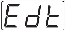
1ST SELECT
001 GR Piano
-
Turn [VALUE] to select the desired tone.
-
Only those tones in the category chosen in Step 3 will be displayed.

For details on the types of tone, refer to "Tone List" (p. 122).
-
Press [WRITE] to perform the Patch Write operation (p. 36).
-
After performing the Patch Write operation, you will automatically return to Play mode.
- If you don't want to save the Patch, press [PLAY] to return to Play mode.
- If "LAYER" is set to "Mute," "1st Tone," or "2nd Tone," either the 1st or 2nd tone—or neither tone—will sound. Change the LAYER setting as necessary.

For details on "LAYER" settings, refer to "Determining which tone will be sounded by each string (LAYER)" (p. 51).
Increasing/Decreasing Attack Time (ATTACK)
With the "ATTACK" setting, you can change the amount of time it takes for the 1st (or 2nd) tone you selected with 1ST SELECT (or 2ND SELECT) to rise to its highest volume. Use this setting to control whether the tone starts with a gentle rise, or with a sharp attack.
Changing the ATTACK TIME
- Select the patch whose ATTACK you wish to change, and press [TONE] to enter Patch Edit mode.
-
Press [PARAMETER] to select "1ST ATTACK."
-
If you want to change the ATTACK TIME of the 2nd tone, choose "2ND ATTACK."
- By pressing [TONE] you can switch between "1ST ATTACK" and "2ND ATTACK."

1ST ATTACK

-
Turn [VALUE] to select a value in the range of -50-50. With higher values, the volume of the sound rises to its full level more slowly. Decreasing the value changes this to a fast attack, like a percussion instrument's. (Setting the value to "0" means that the selected tone's original attack will be used.)
-
The ATTACK setting adjusts each tone's individual attack characteristics. Depending on the tone's original attack, the amount of possible change varies with the selected tone.
-
Press [WRITE] to perform the Patch Write operation (p. 36).
-
After performing the Patch Write operation, you will automatically return to Play mode.
- If you don't want to save the Patch, press [PLAY] to return to Play mode.
- If "LAYER" is set to "Mute," "1st Tone," or "2nd Tone," either the 1st or 2nd tone—or neither tone—will sound. Change the LAYER setting as necessary.

For details on "LAYER" settings, refer to "Specifying which tone will be sounded by each string (LAYER)" (p. 51).
Changing Tone Release (RELEASE)
With the "RELEASE" setting, you can change the decay of the 1st (or 2nd) tone you selected with 1ST SELECT (or 2ND SELECT). By increasing the release time, the sound fades away more gradually at the end of a note, even after the strings stop vibrating. With a short release, the sound stops at the moment the string stops vibrating, allowing you to play staccato, with real "bite."
Changing the Release
- Select the patch whose RELEASE you want to change, and press [TONE] to enter Patch Edit mode.
-
Press [PARAMETER] to select "1ST RELEASE."
-
If you want to change the RELEASE of the 2nd tone, choose "2ND RELEASE."
- By pressing [TONE] you can switch between "1ST RELEASE" and "2ND RELEASE."
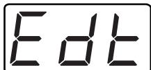
1ST RELEASE

- Turn [VALUE] to select a value in the range of -50-50. Increasing the value setting will lengthen the release time. Decreasing the value will shorten the release time. (Setting the value to "0" causes the original release of the selected tone to be used.)
-
The release setting is a method of adjusting each tone's individual release characteristics. Depending on the way in which the original tone ends, the amount of possible change varies with the selected tone.
-
Press [WRITE] to perform the Patch Write operation (p. 36).
-
After performing the Patch Write operation, you will automatically return to Play mode.
- If you don't want to save the Patch, press [PLAY] to return to Play mode.
- If "LAYER" is set to "Mute," "1st Tone," or "2nd Tone," either the 1st or 2nd tone—or neither tone—will sound. Change the LAYER setting as necessary.

For details on "LAYER" settings, refer to "Determining Which Tones Will Be Sounded (LAYER)" (p. 51).
Changing Tone Brightness (BRIGHTNESS)
By setting the "BRIGHTNESS" of the 1st (or 2nd) tone that you selected with 1ST SELECT (or 2ND SELECT), you can change the brightness of the patch. Changing the value adjusts the setting of the internal digital filter—an effect resembling a electric guitar's tone knob, but reinforced with digital circuitry—making the sound brighter (harder) or darker (softer).
(^*1) Digital filter:
A digital circuit that produces an effect that is similar to, but even more powerful than, the effect of an electric guitar's tone control knob.
Changing the Brightness
- Select the patch whose BRIGHTNESS you want to change, and press [COMMON] to enter Patch Edit mode.
-
Press [PARAMETER] to select "1ST BRIGHTNESS."
-
If you want to change the BRIGHTNESS of the 2nd tone, choose "2ND BRIGHTNESS."
- By pressing [TONE] you can switch between "1ST BRIGHTNESS" and "2ND BRIGHTNESS."

1ST BRIGHTNESS

-
Turn [VALUE] to select a value in the range of -50-50. Increasing the value will make the sound brighter and crisper. Decreasing the value will create a darker, muffled sound. (Setting the value to "0" preserves the original brightness of the selected tone.)
-
The brightness setting is a method of adjusting each tone's brightness characteristics. Depending on the tone's original sound, the amount of possible change varies with the selected tone.
-
Press [WRITE] to perform the Patch Write operation (p. 36).
-
After performing the Patch Write operation, you will automatically return to Play mode.
- If you don't want to save the Patch, press [PLAY] to return to Play mode.
- If LAYER is set to "Mute," "1st Tone," or "2nd Tone," either the 1st or 2nd tone—or neither tone, will sound. Change the LAYER setting as necessary.

For details on LAYER settings, refer to "Determining Which Tones Will Be Sounded (LAYER)" (p. 51).
Combining/Layering Two Sounds (Tones)
Determining Which Tones Will Be Sounded (LAYER)
You can determine how the 1st and 2nd tones will be combined using the TONE "LAYER" parameter in Patch Edit mode. This parameter allows you to activate only the 1st tone, only the 2nd, or both.
LAYER, combined with the [STRING SELECT] button, allows you to set up each string separately.
For example, you can group Strings 1 to 3 and Strings 4 to 6, and then set each group to play different tones.
Procedure for Changing the Layer Settings of the 1st and 2nd Tones
- Select the patch whose LAYER setting you want to change, and press [TONE] to enter Patch Edit mode.
- Press [PARAMETER] to select "LAYER."
LAYER
Both Tone
- Press [STRING SELECT] to select the string you wish to set up.

For more detailed information about the "STRING SELECT" button, refer to "Making separate settings for each string (STRING SELECT)" (p. 35).
-
When you want to set up all of the strings at once, choose "ALL."
-
Turn [VALUE] to select the desired setting.
Mute: Neither the 1st or 2nd tone will sound.
1st Tone: Only the 1st tone will sound.
2nd Tone: Only the 2nd tone will sound.
Both Tone: Both the 1st and 2nd tones will sound.
Weak Detune: A slight amount of detuning.
Strong Detune: A large amount of detuning.

For details on detune, refer to "Applying detune (Subtle Pitch Shift)."
-
If you wish to set up other strings, repeat Steps 3-4.
-
Press [WRITE] to perform the Patch Write operation (p. 36).
-
After performing the Patch Write operation, you will automatically return to Play mode.
- If you don't want to save the Patch, press [PLAY] to return to Play mode.
Applying Detune (Subtle Pitch Shift)
In Step 4 of the previous (LAYER) section, when you select either "Weak Detune" or "Strong Detune," both the first and second tones are played, and a detune effect that slightly offsets the pitch of each tone is added. Strong detune creates a much greater difference in the tones' pitch.
Detuning can add "thickness" to patches. You can make a patch sound quite huge by detuning a patch's tones, and then panning them left and right by setting the COMMON "PAN MODE" parameter (p. 41) to "Cross Tones" and positioning the tones to the left and right. Since detune is one of the "LAYER" settings, you can use it in combination with the "STRING SELECT" button to set the detuning for each string (p. 35).
Transposing by Semitones (TRANSPOSE)
Ordinarily in the GR-33, the pitch of the synth sound is the same as the guitar's. When the need arises, you can change this pitch relationship, offsetting it by semitones—this is called "transpose." By transposing, you can change the synthesizer's sound by different intervals—an octave, fifth, or the like—and then layer the synth sound with the sound of the guitar.
Also, with the built-in transpose setting, you can create separate transposition settings for the 1st ("1ST TRANSPOSE") and 2nd ("2ND TRANSPOSE") tones. This allows you to achieve a bigger, fatter sound by, for example, transposing both of the synthesizer sounds together, or by lowering one tone by an octave, and raising the other by a fifth from your guitar's original pitch.
When used in combination with the "STRING SELECT" button, you can set the transposition for each string individually.
Changing the Transposition of the Tone
- Select the patch whose TRANSPOSE you want to change, and press [TONE] to enter Patch Edit mode.
-
Press [PARAMETER] to select "1ST TRANSPOSE."
-
If you want to change the TRANSPOSE of the 2nd tone, choose "2ND TRANSPOSE."
- By pressing [TONE] you can switch between "1ST TRANSPOSE" and "2ND TRANSPOSE."
1ST TRANSPOSE
图
- Use [STRING SELECT] to select the string you wish to set up.

For more detailed information about the "STRING SELECT" button, refer to "Making separate settings for each string (STRING SELECT)" (p. 35).
-
When you want to make settings to all of strings together, choose "ALL."
-
Turn [VALUE] to select the desired value.
The available range of transposition, by semitone units, is -36 to +24. Setting the transposition to "12" raises the pitch by one octave; set it to "-24," and the pitch is shifted downward two octaves.
-
If you wish to set up other strings, repeat Steps 3-4.
-
Press [WRITE] to perform the Patch Write operation (p. 36).
-
After performing the Patch Write operation, you will automatically return to Play mode.
- If you don't want to save the Patch, press [PLAY] to return to Play mode.
- If LAYER is set to "Mute," "1st Tone," or "2nd Tone," either the 1st or 2nd tone—or neither tone—will sound. Change the LAYER setting as necessary.

For details on LAYER settings, refer to (p. 51).
Determining the Volume Balance of Two Tones (1:2 BALANCE)
When the 1st and second tones are being played simultaneously, you will need to balance the volume of the two tones. You can set the tone balance for each patch using the TONE "1:2 BALANCE" parameter in Patch Edit mode.
Balancing the Volume of Two Tones
- Select the patch whose setting you want to change, and press [TONE] to enter Patch Edit mode.
- Before changing the setting, set "LAYER" (p. 51) so both 1st and 2nd tones play: select "Both Tone," "Weak Detune," or "Strong Detune".
- Press [PARAMETER] to select "1:2 BALANCE."
1:2 BALANCE

- Turn [VALUE] to select a value in the range of -50-50. Setting the parameter to "50" causes only the 1st tone to sound, while "-50" causes only the 2nd tone to sound. "0" causes both tones to sound at equal volume.
-
Press [WRITE] to perform the Patch Write operation (p. 36).
-
After performing the Patch Write operation, you will automatically return to Play mode.
- If you don't want to save the Patch, press [PLAY] to return to Play mode.
What to do When a Tone is Supposed to Sound, but Doesn't
In cases where only the 1st or 2nd tone can be heard, one of the following may be the cause. Check the following items, and if one of them turns out to be the problem, refer to the specified page and change your settings accordingly.
All or one of the strings is set to "1st Tone" (1st tone only) or "2nd Tone" (2nd tone only), in LAYER (p. 51).
Is the "1:2 BALANCE" setting (p. 52) set to "50" or "-50"?
When "Cross Tones" is selected as the COMMON "PAN MODE" setting (p. 41) and the tones are panned left and right (50 and -50), only one channel is being output from your amp.
- "Volume 1st," "Volume 2nd," or "Balance" are selected as the expression pedal setting (p. 47), and the pedal is all the way back (or all the way forward).
* When neither the 1st nor 2nd tones can be heard, please refer to p. 99 and consult the checklist there.
Chapter 6 Using the Built-in Effects
About the Effects Processors and Available Effects
The GR-33 has the following three onboard effect processors.
a. MULTI-FX (Multi-effects)
b. CHORUS
c. REVERB
The overall structure of the EFFECTS as follows.
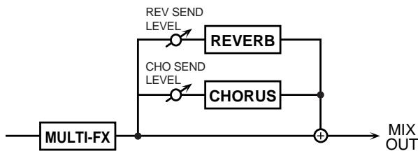
Chorus and Reverb connectcs in series.
MULTI-FX is Multi-effects which contains 40 types of effect, including distortion and delay. The MULTI-FX also has effect types named "Chorus," and "Reverb" but these can be applied separately from the Chorus (b) and Reverb (c) listed above. It is also possible to apply the effect to just one of the two tones.
Chorus is an effect that gives a wide, open sound, with a special type of wavering, like that of multiple instruments playing together.
Reverb is an effect that simulates the reverberation you get when performing in a room or hall with good acoustics. With the GR-33's built-in reverb, you also get delay (an effect that repeats a sound, sort of like a mountain echo).
The on/off settings of these effects can be stored for each patch.
- These effects are for use with the built-in sound generator. They don't work with guitar sounds or any other than the internal synth sound generator. However, if you use the GUITAR OUT (RETURN) jack, you can make additional connections to add external guitar-only effects. (p. 15)
- You may hear a noise when changing effects, but this does not indicate a malfunction.
Making Multi-effects Settings
Turning multi-effects on/off (MULTI-FX SW)
Use "MULTI-FX SW" to select the tone for which the multi-effect will be turned on/off, or to which the multi-effect will be applied.
Procedure for Multi-effect On/Off
- Select the patch for which Multi-effect is to be set, and press [EFFECTS] to go into Patch Edit mode.
- Use [PARAMETER] to select "MULTI-FX SW."
MULTI-FX SW Both
- Use [VALUE] to select the value.
Off: Turn off the multi-effect.
1st: Apply the multi-effect only to the 1st tone.
2nd: Apply the multi-effect only to the 2nd tone.
Both: Apply the multi-effect to both the 1st and the 2nd tones.
-
Press [WRITE] to perform the Patch Write operation (p. 36) and save the data.
-
After performing the Patch Write operation, you will automatically return to Play mode.
- If you don't want to save the Patch, press [PLAY] to return to Play mode.
HINT
In Pedal Effect mode (or if you have chosen "Patch Select" as the "S1/S2 FUNCTION"), you can press the pedal 4 (CTRL) to switch multi-effect bypass on/off while you play. However, you must make "CTRL PEDAL" settings (p. 46).
You can also press pedal 4 (CTRL) to switch bypass on/off for the multi-effect in Patch Edit mode as well if a multi-effect related setting item is selected.
Selecting a Type (MULTI-FX TYPE)
Multi Effects provides 40 different effects types (MULTI-FX TYPE). For each of these effect types, you can specify parameter values. By changing these parameters, various effects can be applied.
Parameters for each effects type are given on the following pages.
1: STEREO-EQ ( p.55)
2: OVERDRIVE ( p.55)
3: DISTORTION (→p. 56)
4: PHASER (→p. 56)
5: SPECTRUM (→p. 56)
6: ENHANCER (→p. 57)
7: AUTO-WAH ( p.57)
8: ROTARY (→p. 57)
9: COMPRESSOR (→p. 58)
10: LIMITER (→p. 58)
11: HEXA-CHO (→p. 59)
12: TREMOLO-CHORUS (→p. 59)
13: SPACE-D ( p.60)
14: STEREO-CHO (→p. 60)
15: STEREO-FL ( p.61)
16: STEP-FL ( p.61)
17: STEREO-DELAY (→p. 62)
18: MOD-DELAY (→p. 63)
19: 3-TAP-DELAY (→p. 63)
20: 4-TAP-DELAY (→p. 64)
21: TIMECTRL-DLY (→p. 65)
22: 2VOICE-P. SFT ( p.65)
23: FB-P. SFT (→p. 66)
24: REVERB (→p. 67)
25: GATE-REVERB (→p. 67)
26: OD→CHO (→p. 68)
27: OD→FL (→p. 68)
28: OD→DLY (→p. 69)
29: DS→CHO (→p. 69)
30: DS→FL (→p. 69)
31: DS→DLY (→p. 69)
32: EH→CHO (→p. 70)
33: EH→FL (→p. 70)
34: EH→DLY (→p. 71)
35: CHO DLY (→p. 71)
36: FL→DLY (→p. 72)
37: CHO→FL (→p. 72)
38: CHO/DLY ( p.73)
39: FL/DLY (→p. 73)
40: CHO/FL ( p.73)
Making Multi-effects Settings
- Select the patch for which Multi-effect is to be set, and press [EFFECTS] to go into Patch Edit mode.
- Use [PARAMETER] to select "MULTI-FX TYPE."
MULTI-FX TYPE 1: STEREO-EQ
- Use [VALUE] to select the effect type.
- Press [PARAMETER] to select the setting item for the effect type selected in step 3.
For a description of the effect type parameters, see the subsequent section, "About Multi-Effects Parameters."
- Use [VALUE] to select the value.
- Repeat steps 4 to 5 to set all parameters of the selected effect type.
-
Press [WRITE] to perform the Patch Write operation (p. 36).
-
After performing the Patch Write operation, you will automatically return to Play mode.
- If you don't want to save the Patch, press [PLAY] to return to Play mode.
The value of effect type items (parameters) marked with a “#” symbol can be controlled by the EXP pedal. For details on EXP pedal settings, refer to “Using the expression pedal” (p. 47).
About Multi-Effects Parameters
1: STEREO-EQ (Stereo equalizer)
This is a stereo equalizer which allows you to adjust the tone quality using a low range, two mid-range, and a high range control.
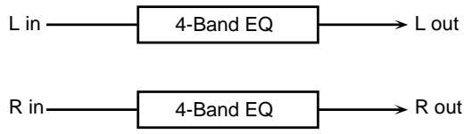
LOW FREQ (Low frequency) 200 Hz/400 Hz
Select the frequency (200Hz / 400Hz) at which the low frequency range will be adjusted.
LOW GAIN -15-+15 dB
Specify the low frequency gain (amount of boost or cut). Positive (+) settings will emphasize (boost) the low range.
HIGH FREQ (High frequency) 4000 Hz/8000 Hz
Select the frequency (4 kHz/8 kHz) at which the high range will be adjusted.
HIGH GAIN -15-+15 dB
Specify the high frequency gain (amount of boost or cut). Positive (+) settings will emphasize (boost) the high range.
P1 FREQ (Peaking 1 frequency)
200/250/315/400/500/630/800/1000/1250/1600/2000/2500/3150/ 4000/5000/6300/8000 (200-8000 Hz)
Specify the center frequency of the region in which the boost or cut will take place.
P1 Q (Peaking 1 Q) 0.5/1.0/2.0/4.0/8.0
Specify the width of the region centered on the P1 FREQ setting.
Higher settings will cause the region affected by P1 GAIN to be narrower.
P1 GAIN (Peaking 1 gain) -15-+15 dB
Specify the gain (amount of boost or cut) that will take place in the region specified by P1 FREQ and P1 Q.
Positive (+) settings will emphasize (boost) the region specified by P1 FREQ and P1Q.
P2 FREQ (Peaking 2 frequency)
200/250/315/400/500/630/800/1000/1250/1600/2000/2500/3150/ 4000/5000/6300/8000 (200-8000 Hz)
Specify the center frequency of the region in which the boost or cut will take place.
P2 Q (Peaking 2 Q) 0.5/1.0/2.0/4.0/8.0
Specify the width of the region centered on the P2 FREQ setting.
Higher settings will cause the region affected by P2 GAIN to be narrower.
P2 GAIN (Peaking 2 gain) -15-+15 dB
Specify the gain (amount of boost or cut) that will take place in the region specified by P2 FREQ and P2 Q.
Positive (+) settings will emphasize (boost) the region specified by P2 FREQ and P2Q.
LEVEL (Output level) 0-127 #
Specify the output volume.
2:OVERDRIVE
Overdrive produces a natural-sounding distortion similar to that produced by a vacuum tube amplifier.
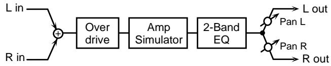
DRIVE 0-127 #
Specify the depth of distortion. The volume will change together with the depth of distortion.
PAN (Output pan) L64-0-R63
Specify the stereo location of the output sound.
A setting of L64 is far left, 0 is center, and R63 is far right.
AMP TYPE (Amp simulator type) Small/Built-In/2-Stack/3-Stack
Select the type of guitar amp.
Small: Small amp
Built-In: Built-in type amp
2-Stack: Large two-level stack
3-Stack: Large three-level stack
LOW GAIN -15--+15 dB
Adjust the low frequency gain (amount of boost or cut). Positive (+) settings will emphasize (boost) the low frequency range.
HIGH GAIN -15-+15 dB
Adjust the high frequency gain (amount of boost or cut). Positive (+) settings will emphasize (boost) the high frequency range.
LEVEL (Output level) 0-127
Specify the output volume.
You can use the Output Level setting to even out the volume difference between the sound with and without Overdrive.
3: DISTORTION
Distortion produces a more intense distortion than the Overdrive effect.
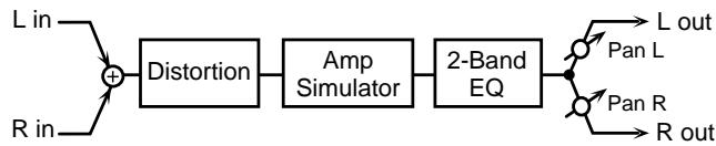
DRIVE 0-127 #
Adjust the amount of distortion. The volume will change together with the amount of distortion.
PAN (Output pan) L64-0-R63
Specify the stereo location of the output sound.
A setting of L64 is far left, 0 is center, and R63 is far right.
AMP TYPE (Amp simulator type) Small/Built-In/2-Stack/3-Stack
Specify the type of guitar amp.
Small: Small amp
Built-In: Built-in type amp
2-Stack: Large two-level stack
3-Stack: Large three-level stack
LOW GAIN -15--+15 dB
Specify the low range gain (amount of boost or cut).
Positive (+) settings will emphasize (boost) the low frequency range.
HIGH GAIN -15-+15 dB
Specify the high range gain (amount of boost or cut). Positive (+) settings will emphasize (boost) the high frequency range.
LEVEL (Output level) 0-127
Specify the output volume.
You can use the Output Level setting to even out the volume difference between the sound with and without Distortion.
4:PHASER
Phaser is an effect that adds a phase-shifted sound to the original sound to create time-varying change, modulating the sound.
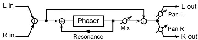
MANUAL 100 Hz-8000 Hz
Specify the center frequency at which the sound is modulated.
RATE 0.05-10.0 Hz #
Specify the frequency of modulation.
DEPTH 0-127
Specify the depth of modulation.
RESONANCE 0-127
Specify the amount of feedback for the phaser. Higher settings will give the sound a stronger character.
MIX (Mix level) 0-127
Adjust the ratio with whitch the phase-shifted sound is combined with the direct sound.
PAN (Output pan) L64-0-R63
Specify the stereo location of the output sound.
A setting of L64 is far left, 0 is center, and R63 is far right.
LEVEL (Output level) 0-127
Specify the output volume.
5: SPECTRUM
Spectrum is a type of filter which boosts or cuts the level at specific frequencies to modify the tone.
It functions similarly to the equalizer, but since the eight frequencies are fixed at positions ideal for giving the sound more character, more distinctive sounds can be created.
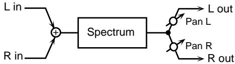
Determines the tone quality of Bands 1-8.
BAND1 (Band 1 gain) -15-+15 dB
Specify the gain (amount of boost or cut) at 250Hz .
BAND2 (Band 2 gain) -15--+15 dB
Specify the gain (amount of boost or cut) at 500Hz .
BAND3 (Band 3 gain) -15--+15 dB
Specify the gain (amount of boost or cut) at 1000Hz .
BAND4 (Band 4 gain) -15-+15 dB
Specify the gain (amount of boost or cut) at 1250Hz .
BAND5 (Band 5 gain) -15-+15 dB
Specify the gain (amount of boost or cut) at 2000Hz .
BAND6 (Band 6 gain) -15-+15 dB
Specify the gain (amount of boost or cut) at 3150Hz .
BAND7 (Band 7 gain) -15--+15 dB
Specify the gain (amount of boost or cut) at 4000Hz .
BAND8 (Band 8 gain) -15-+15 dB
Specify the gain (amount of boost or cut) at 8000Hz .
Q 0.5/1.0/2.0/4.0/8.0
Specify the range of all bands in which the level will be modified.
PAN (Output pan) L64-0-R63
Specify the stereo location of the output sound.
A setting of L64 is far left, 0 is center, and R63 is far right.
LEVEL (Output level) 0-127 #
Specify the output volume.
6: ENHANCER
Enhancer controls the overtone structure of the high frequency range, adding sparkle to the sound and improving the definition.
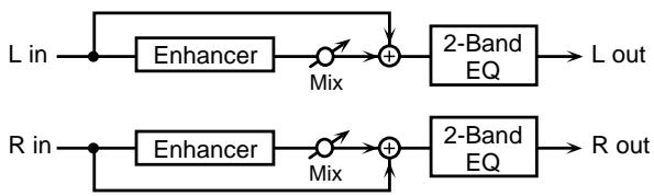
SENS (Sensitivity) 0-127
Specify the depth of the Enhancer effect.
MIX (Mix level) 0-127 #
Specify the proportion by which the overtones generated by the enhancer will be mixed with the original sound.
LOW GAIN -15--+15 dB
Specify the low frequency gain (amount of boost or cut).
Positive (+) settings will emphasize (boost) the low frequency range.
HIGH GAIN -15-+15 dB
Specify the high frequency gain (amount of boost or cut).
Positive (+) settings will emphasize (boost) the high frequency range.
LEVEL (Output level) 0-127
Specify the output volume.
7: AUTO-WAH
Auto Wah cyclically moves the frequency of a filter to produce a wah effect (cyclic modulation of the tone).
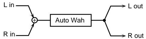
FILTER TYPE LPF/BPF
Specify the type of filter.
LPF:
The wah effect will be produced over a wide frequency range.
BPF:
The wah effect will be produced over a narrow frequency range.
RATE 0.05-10.0 Hz
Specify the modulation frequency of the wah effect.
DEPTH 0-127
Specify the modulation depth of the wah effect.
SENS (Sensitivity) 0-127
Specify the sensitivity with which the filter will be affected.
MANUAL 0-127 #
Specify the center frequency at which the wah effect will be produced.
PEAK 0-127
Specify how the wah effect will affect the region around the center frequency.
Lower settings will produce a wah effect in a broad area around the center frequency. Higher settings will produce a wah effect in a narrow area around the center frequency.
LEVEL (Output level) 0-127
Specify the output volume.
8: ROTARY
Rotary is an effect which simulates the sound of the rotary speakers of the past. Since the movement of the high frequency and low frequency rotors can be specified separately, the unique modulation can be simulated realistically. This effect is most effective on organ-type Patches.
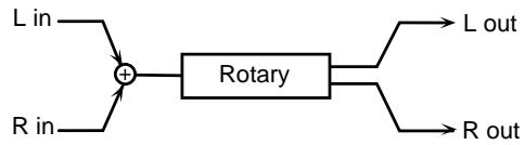
HIGH SLOW
(High frequency slow rate) 0.05-10.0 Hz
Specify the low-speed (SLOW) rotational speed of the high-range rotor.
LOW SLOW
(Low frequency slow rate) 0.05-10.0 Hz
Specify the low-speed (SLOW) rotational speed of the low-range rotor.
HIGH FAST
(High frequency fast rate) 0.05-10.0 Hz
Specify the high-speed (FAST) rotational speed of the high-range rotor.
LOW FAST
(Low frequency fast rate) 0.05-10.0 Hz
Specify the high-speed (FAST) rotational speed of the low-range rotor.
SPEED Slow/Fast #
Select the rotational speed of the low-range rotor and high-range rotor.
Slow:
The specified rotational speeds (the LOW SLOW RATE/ HI SLOW RATE values) will take effect.
Fast:
The specified rotational speeds (the LOW FAST RATE/ HI FAST RATE values) will take effect.
HIGH ACCL (High frequency acceleration) 0-15
Specify the time required for the rotational speed of the high-range rotor to change from the low speed to the high speed (or from the high speed to the low speed). More time will be required as the value of this parameter is decreased.
LOW ACCL (Low frequency acceleration) 0-15
Specify the time required for the rotational speed of the low-range rotor to change from the low speed to the high speed (or from the high speed to the low speed). More time will be required as the value of this parameter is decreased.
HIGH LEVEL (High frequency level) 0-127
Specify the volume of the high-range rotor.
LOW LEVEL (Low frequency level) 0-127
Specify the volume of the low-range rotor.
SEPARATION 0-127
Specify the spaciousness of the sound.
LEVEL (Output level) 0-127
Specify the output volume.
9: COMPRESSOR
Compressor is an effect which restricts high sound levels and boosts low sound levels, thus smoothing out variations in volume.
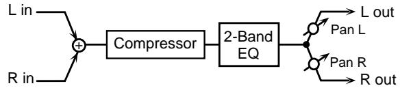
SUSTAIN 0-127
Specify the time over which low-level sounds are boosted to a constant volume level.
ATTACK 0-127
Specify the attack time of the input sound.
PAN (Output pan) L64-0-R63
Specify the stereo location of the output sound.
A setting of L64 is far left, 0 is center, and R63 is far right.
POST GAIN 0/+6/+12/+18 dB
Specify the output level.
LOW GAIN -15-+15 dB
Specify the low frequency range gain (amount of boost or cut). Positive (+) settings will emphasize (boost) the low frequency range.
HIGH GAIN -15-+15 dB
Specify the high frequency range gain (amount of boost or cut).
Positive (+) settings will emphasize (boost) the high frequency range.
LEVEL (Output level) 0-127 #
Specify the output volume.
10: LIMITER
Limiter is an effect which compresses sounds that are louder than a specified volume level, preventing distortion from occurring.
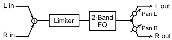
THRESHOLD (Threshold level) 0-127
Specify the volume level at which compression will begin.
RELEASE (Release time) 0-127
Specify the time from when the volume falls below the threshold level until the limiter effect no longer applies.
RATIO (Compression ratio) 1.5:1/2:1/4:1/100:1
Specify the compression ratio.
PAN (Output pan) L64-0-R63
Specify the stereo location of the output sound.
A setting of L64 is far left, 0 is center, and R63 is far right.
POST GAIN 0/+6/+12/+18 dB
Specify the level of the output sound.
LOW GAIN -15--+15 dB
Specify the gain (amount of boost or cut) for the low frequency range.
Positive (+) settings will emphasize (boost) the low frequency range.
HIGH GAIN -15-+15 dB
Specify the gain (amount of boost or cut) for the high frequency range.
Positive (+) settings will emphasize (boost) the high frequency range.
LEVEL (Output level) 0-127 #
Specify the output volume.
11: HEXA-CHORUS
Hexa-chorus is a six-stage chorus which adds depth and spaciousness to the sound. (Six chorus sounds with different delay times are overlaid.)
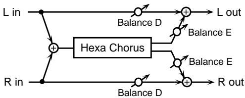
PRE DELAY (Pre delay time) 0.0-100 ms
Specify the delay time from the original sound until when the chorus sound is heard.
RATE 0.05-10.0 Hz #
Specify the modulation frequency of the chorus sound.
DEPTH 0-127
Specify the modulation depth of the chorus sound.
PRE DLY DEV (Pre delay deviation) 0-20
The Pre Delay parameter explained above specified the delay time from the original sound until when the chorus sound is heard. This Pre Delay Deviation parameter specifies the differences in Pre Delay time for each of the chorus sounds. Higher settings will cause each of the chorus sounds to be spread further apart.
DEPTH DEV (Depth deviation) -20--+20
Specify the difference in modulation depth between each of the chorus sounds.
PAN DEV (Pan deviation) 0-20
Specify the difference in stereo position between each of the chorus sounds.
With a setting of 0, all of the chorus sounds will be panned to the center. Setting this to 20 provides the greatest breadth.
BALANCE (Effect balance) D100:OE-D0:100E
Specify the volume balance between the original sound and the chorus sound.
With a setting of D100:0E only the original sound will be output, and with a setting of D0:100E only the chorus sound will be output.
LEVEL (Output level) 0-127
Specify the output volume.
12: TREMOLO-CHO (Tremolo Chorus)
Tremolo-chorus is a chorus with a tremolo effect (cyclic modulation of volume).
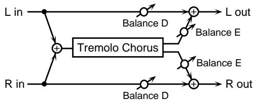
PRE DELAY (Pre delay time) 0.0-100 ms
Specify the delay time from the original sound until when the chorus sound is heard.
CHORUS RATE 0.05-10.0 Hz
Specify the modulation frequency of the chorus sound.
CHORUS DEPTH 0-127
Specify the modulation depth of the chorus sound.
TREM RATE (Tremolo rate) 0.05-10.0 Hz #
Specify the modulation frequency of the tremolo effect.
TREM SEP (Tremolo separation) 0-127
Specify the spaciousness of the tremolo effect.
TREM PHASE (Tremolo phase) 0-180
Adjusts the phase of the tremolo effect.
BALANCE (Effect balance) D100:OE-D0:100E
Specify the volume balance between the original sound and the tremolo-chorus sound.
With a setting of D100:0E only the original sound will be output, and with a setting of D0:100E only the tremolochorus sound will be output.
LEVEL (Output level) 0-127
Specify the output volume.
13: SPACE-D
Space-D is a multiple chorus that applies two-stage modulation in stereo. It does not produce a sense of modulation, but creates a transparent chorus effect.
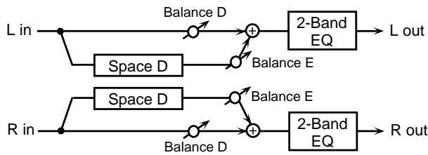
PRE DELAY (Pre delay time) 0.0-100 ms
Specify the delay time from the original sound until the chorus sound is heard.
RATE 0.05-10.0 Hz #
Specify the modulation frequency of the chorus sound.
DEPTH 0-127
Specify the modulation depth of the chorus sound.
PHASE 0-180
Specify the spaciousness of the chorus sound.
LOW GAIN -15--+15 dB
Specify the gain (amount of boost or cut) for the low frequency range.
Positive (+) settings will emphasize (boost) the low frequency range.
HIGH GAIN -15-+15 dB
Specify the gain (amount of boost or cut) for the high frequency range.
Positive (+) settings will emphasize (boost) the high frequency range.
BALANCE (Effect balance) D100:OE-D0:100E
Specify the volume balance between the original sound and the chorus sound.
With a setting of D100:0E only the original sound will be output, and with a setting of D0:100E only the chorus sound will be output.
LEVEL (Output level) 0-127
Specify the output volume.
14: STEREO-CHO (Stereo Chorus)
This is a stereo chorus. A filter allows you to adjust the tone of the chorus sound.
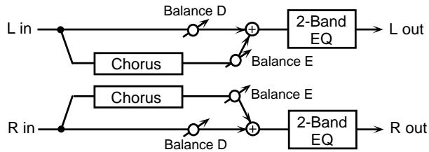
FILTER TYPE Off/LPF/HPF
Select the type of filter.
Off:
A filter will not be used.
LPF:
The frequency region above the Cutoff Freq setting will be cut.
HPF:
The frequency region below the Cutoff Freq setting will be cut.
CUTOFF FREQ (Cutoff frequency)
200/250/315/400/500/630/800/1000/1250/1600/2000/2500/3150/ 4000/5000/6300/8000 (200-8000 Hz)
Specify the frequency at which the filter will begin cutting.
PRE DELAY (Pre delay time) 0.0-100 ms
Specify the time delay from the original sound until the chorus sound is heard.
RATE 0.05-10.0 Hz #
Specify the modulation frequency of the chorus sound.
DEPTH 0-127
Specify the modulation depth of the chorus sound.
PHASE 0-180
Specify the spaciousness of the chorus sound.
LOW GAIN -15-+15 dB
Specify the gain (amount of boost or cut) for the low frequency range.
Positive (+) settings will emphasize (boost) the low frequency range.
HIGH GAIN -15-+15 dB
Specify the gain (amount of boost or cut) for the high frequency range.
Positive (+) settings will emphasize (boost) the high frequency range.
BALANCE (Effect balance) D100:OE-D0:100E
Specify the volume balance between the original sound and the chorus sound.
With a setting of D100:0E only the original sound will be output, and with a setting of D0:100E only the chorus sound will be output.
LEVEL (Output level) 0-127
Specify the output volume.
15: STEREO-FL (Stereo Flanger)
This is a stereo flanger (the LFO has the same phase for left and right). This produces a metallic resonance reminiscent of a jet airplane taking off and landing. A filter is provided so that you can adjust the tone of the flanger sound.
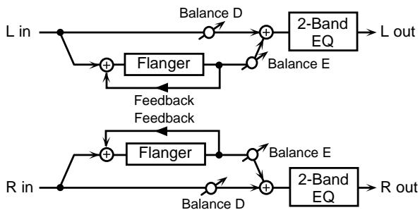
FILTER TYPE Off/LPF/HPF
Specify the type of filter.
Off:
A filter will not be used.
LPF:
Cut the frequency region above the Cutoff Freq setting.
HPF:
Cut the frequency region below the Cutoff Freq setting.
CUTOFF FREQ (Cutoff frequency)
200/250/315/400/500/630/800/1000/1250/1600/2000/2500/3150/ 4000/5000/6300/8000 (200-8000 Hz)
Specify the frequency at which the filter will begin cutting.
PRE DELAY (Pre delay time) 0.0-100 ms
Specify the time delay from the original sound until the flanger sound is heard.
RATE (LFO rate) 0.05-10.0 Hz #
Specify the modulation frequency of the flanger sound.
DEPTH (LFO depth) 0-127
Specify the modulation depth of the flanger sound.
PHASE 0-180
Specify the spaciousness of the flanger sound.
FEEDBACK -98-+98%
Specify the proportion (%) of the flanger sound that is to be returned to the input.
Positive (+) settings will return the signal to the input with the original phase, while negative (-) settings produce an inverted phase.
Higher settings will produce a more distinctive sound.
LOW GAIN -15--+15 dB
Specify the gain (amount of boost or cut) for the low frequency range.
Positive (+) settings will emphasize (boost) the low frequency range.
HIGH GAIN -15-+15 dB
Specify the gain (amount of boost or cut) for the high frequency range.
Positive (+) settings will emphasize (boost) the high frequency range.
BALANCE (Effect balance) D100:OE-D0:100E
Specify the volume balance between the original sound and the flanger sound.
With a setting of D100:0E only the original sound will be output, and with a setting of D0:100E only the flanger sound will be output.
LEVEL (Output level) 0-127
Specify the output volume.
16: STEP-FL (Step Flanger)
Step flanger is a flanger in which the pitch of the flanger sound changes in steps. The frequency of the pitch change can be specified as a note length of a specific tempo.
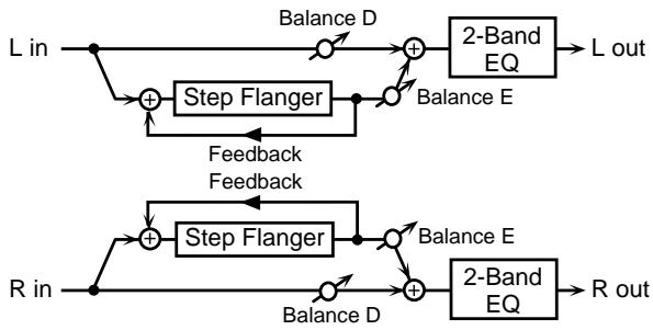
PRE DELAY (Pre delay time) 0.0-100 ms
Specify the time delay from the original sound until the flanger sound is heard.
RATE 0.05-10.0 Hz
Specify the modulation frequency of the flanger sound.
DEPTH 0-127
Specify the modulation depth of the flanger sound.
FEEDBACK -98-+98%
Specify the proportion (%) of the flanger sound that is to be returned to the input.
Positive (+) settings will return the signal to the input with the original phase, while negative (-) settings produce an inverted phase.
Higher settings will produce a more distinctive sound.
STEP RATE 0.05-10.0 Hz #
Specify the frequency of pitch change.
PHASE 0-180
Specify the spaciousness of the flanger sound.
LOW GAIN -15--+15 dB
Specify the gain (amount of boost or cut) for the low frequency range.
Positive (+) settings will emphasize (boost) the low frequency range.
HIGH GAIN -15-+15 dB
Specify the gain (amount of boost or cut) for the high frequency range.
Positive (+) settings will emphasize (boost) the high frequency range.
BALANCE (Effect balance) D100:OE-D0:100E
Specify the volume balance between the original sound and the flanger sound.
With a setting of D100:0E only the original sound will be output, and with a setting of D0:100E only the flanger sound will be output.
LEVEL (Output level) 0-127
Specify the output volume.
17:STEREO-DELAY
This is a stereo delay.
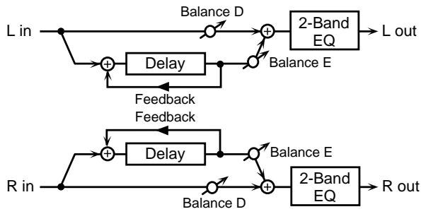
When Feedback Mode parameter is Normal:
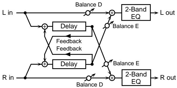
When Feedback Mode parameter is Cross:
FB MODE (Feedback mode) Normal/Cross
Specify the input destination to which the delay sound will be returned.
Normal:
The left delay sound will be returned to the left input, and the right delay sound to the right input.
Cross:
The left delay sound will be returned to the right input, and the right delay sound to the left input.
DELAY LEFT (Delay time left) 0.0-500 ms
Specify the delay time from the original sound until the left delay sound is heard.
DELAY RIGHT (Delay time right) 0.0-500 ms
Specify the delay time from the original sound until the right delay sound is heard.
PHASE LEFT (Feedback phase left) Normal/Invert
Specify the phase of the left delay sound.
Normal: The phase will not change.
Invert: The phase will be inverted.
PHASE RIGHT (Feedback phase right) Normal/Invert
Specify the phase of the right delay sound.
Normal: The phase will not change.
Invert: The phase will be inverted.
FEEDBACK (Feedback level) -98-+98 % #
Specify the proportion (%) of the delay sound that is to be returned to the input.
Positive (+) settings will return the sound to the input with the original phase, while negative (-) settings produce an inverted phase.
HF DAMP
200/250/315/400/500/630/800/1000/1250/1600/2000/2500/3150/ 4000/5000/6300/8000 (200-8000 Hz), Bypass
Specify the frequency at which the high frequency range of the delayed sound returned to the input will be cut.
If you do not want the sound to be cut, select Bypass.
LOW GAIN -15-+15 dB
Specify the gain (amount of boost or cut) for the low frequency range.
Positive (+) settings will emphasize (boost) the low frequency range.
HIGH GAIN -15-+15 dB
Specify the gain (amount of boost or cut) for the high frequency range.
Positive (+) settings will emphasize (boost) the high frequency range.
BALANCE (Effect balance) D100:OE-D0:100E
Specify the volume balance between the original sound and the delay sound.
With a setting of D100:0E only the original sound will be output, and with a setting of D0:100E only the delay sound will be output.
LEVEL (Output level) 0-127
Specify the output volume.
18: MOD-DELAY (Modulation Delay)
Modulation-delay is an effect which adds modulation to the delay sound. It produces a flanger-like effect.
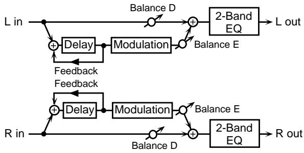
When Feedback Mode parameter is Normal:
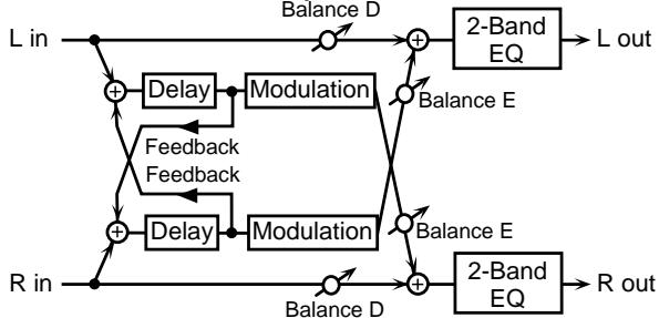
When Feedback Mode parameter is Cross:
FB MODE (Feedback mode) Normal/Cross
Specify the input destination to which the delay sound will be returned.
Normal:
The left delay sound will be returned to the left input, and the right delay sound to the right input.
Cross:
The left delay sound will be returned to the right input, and the right delay sound to the left input.
DELAY LEFT (Delay time left) 0.0-500 ms
Specify the delay time from the original sound until the left delay sound is heard.
DELAY RIGHT (Delay time right) 0.0-500 ms
Specify the delay time from the original sound until the right delay sound is heard.
FEEDBACK (Feedback level) -98-+98 %
Specify the proportion (%) of the delay sound that is to be returned to the input.
Positive (+) settings will return the sound to the input with the original phase, while negative (-) settings produce an inverted phase.
HF DAMP
200/250/315/400/500/630/800/1000/1250/1600/2000/2500/3150/ 4000/5000/6300/8000 (200-8000 Hz), Bypass
Specify the frequency at which the high frequency range of the delay sound returned to the input will be cut.
If you do not want the sound to be cut, select Bypass.
RATE 0.05-10.0 Hz #
Specify the modulation frequency of the modulation effect.
DEPTH 0-127
Specify the modulation depth of the modulation effect.
PHASE 0-180
Specify the spaciousness of the modulation sound.
LOW GAIN -15-+15 dB
Specify the gain (amount of boost or cut) of the low frequency range.
Positive (+) settings will emphasize (boost) the low frequency range.
HIGH GAIN -15-+15 dB
Specify the gain (amount of boost or cut) of the high frequency range.
Positive (+) settings will emphasize (boost) the high frequency range.
BALANCE (Effect balance) D100:OE-D0:100E
Specify the volume balance between the original sound and the modulation-delay sound.
With a setting of D100:0E only the original sound will be output, and with a setting of D0:100E only the modulation-delay sound will be output.
LEVEL (Output level) 0-127
Specify the output volume.
19: 3-TAP-DELAY (Triple Tap Delay)
Triple-tap-delay is an effect that produces delays in three directions: center, left and right. The delay time can also be specified as a note length relative to a specific tempo.
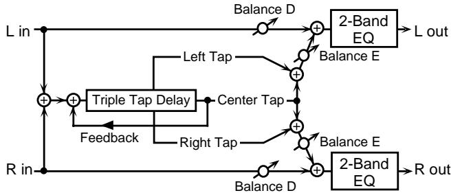
DELAY LEFT (Delay time left) 200-1000 ms
Specify the delay time from the original sound until the left delay sound is heard.
DELAY RIGHT (Delay time right)
Specify the delay time from the original sound until the right delay sound is heard.
- The setting values are the same as for DELAY LEFT.
DELAY CENTER (Delay time center)
Specify the delay time from the original sound until the center delay sound is heard.
- The setting values are the same as for DELAY LEFT.
FEEDBACK (Feedback level) -98%--+98% #
Specify the proportion (%) of the delay sound that is to be returned to the input.
Positive (+) settings will return the sound to the input with the original phase, while negative (-) settings produce an inverted phase.
HF DAMP
200/250/315/400/500/630/800/1000/1250/1600/2000/2500/3150/ 4000/5000/6300/8000 (200-8000 Hz), Bypass
Specify the frequency at which the high frequency range of the delayed sound returned to the input will be cut.
If you do not want the sound to be cut, select Bypass.
LEFT LEVEL 0-127
Specify the volume of the left delay sound.
RIGHT LEVEL 0-127
Specify the volume of the right delay sound.
CENTER LEVEL 0-127
Specify the volume of the center delay sound.
LOW GAIN -15--+15 dB
Specify the gain (amount of boost or cut) for the low frequency range.
Positive (+) settings will emphasize (boost) the low frequency range.
HIGH GAIN -15-+15 dB
Specify the gain (amount of boost or cut) for the high frequency range.
Positive (+) settings will emphasize (boost) the high frequency range.
BALANCE (Effect balance) D100:OE-D0:100E
Specify the volume balance between the original sound and the delay sound.
With a setting of D100:0E only the original sound will be output, and with a setting of D0:100E only the delay sound will be output.
LEVEL (Output level) 0-127
Specify the output volume.
20: 4-TAP-DELAY (Quadruple Tap Delay)
Quadruple-tap-delay provides four delays. The delay time for each delay can be specified as a note length relative to a specific tempo.
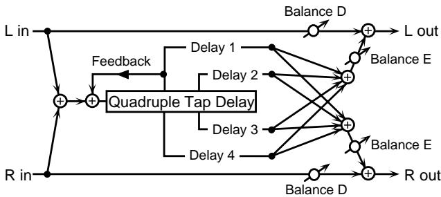
DELAY1 (Delay time 1) 200-1000 ms
Specify the delay time from the original sound until the delay 1 sound is heard.
- The setting values for Delay Time 2 to Delay time 4 are the same.
DELAY2 (Delay time 2)
Specify the delay time from the original sound until the delay 2 sound is heard.
DELAY3 (Delay time 3)
Specify the delay time from the original sound until the delay 3 sound is heard.
DELAY4 (Delay time 4)
Specify the delay time from the original sound until the delay 4 sound is heard.
LEVEL1 0-127
Specify the volume level of delay 1.
LEVEL2 0-127
Specify the volume level of delay 2.
LEVEL3 0-127
Specify the volume level of delay 3.
LEVEL4 0-127
Specify the volume level of delay 4.
FEEDBACK (Feedback level) -98%--+98% #
Specify the proportion (%) of the delay sound that is to be returned to the input.
Positive (+) settings will return the sound to the input with the original phase, while negative (-) settings produce an inverted phase.
HF DAMP
200/250/315/400/500/630/800/1000/1250/1600/2000/2500/3150/ 4000/5000/6300/8000 (200-8000 Hz), Bypass
Specify the frequency at which the high frequency range of the delayed sound returned to the input will be cut.
If you do not want the sound to be cut, select Bypass.
BALANCE (Effect balance) D100:OE-D0:100E
Specify the volume balance between the original sound and the delay sound.
With a setting of D100:0E only the original sound will be output, and with a setting of D0:100E only the delay sound will be output.
LEVEL (Output level) 0-127
Specify the output volume.
21:TIMECTRL-DLY (Time Control Delay)
This lets you control a delay time in real time.
When the delay time has been made to change, the delay time and pitch of the delayed sound change at the speed set for Acceleration. Depending on the settings you use, you can achieve some really tricky effects with this.
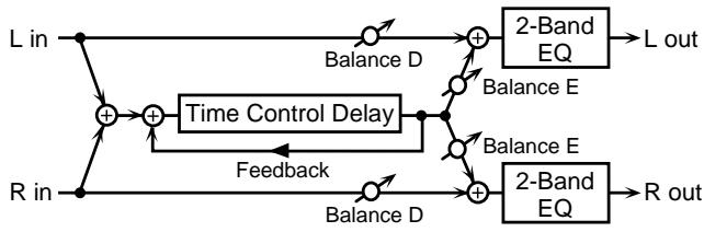
DELAY (Delay time) 200-1000 ms #
Specify the time delay from the original sound until the delay sound is heard.
FEEDBACK (Feedback level) -98-+98 %
Specify the proportion (%) of the delay sound that is to be returned to the input.
Positive (+) settings will return the sound to the input with the original phase, while negative (-) settings produce an inverted phase.
ACCELERATION 0-15
Specify the time over which the current delay time will change to the newly-specified delay time when the delay time is modified. The speed of the pitch change will be proportionate to the delay time.
HF DAMP
200/250/315/400/500/630/800/1000/1250/1600/2000/2500/3150/ 4000/5000/6300/8000 (200-8000 Hz), Bypass
Specify the frequency at which the high frequency range of the delayed sound returned to the input will be cut.
If you do not want the sound to be cut, select Bypass.
PAN (Output pan) L64-0-R63
Specify the stereo position of the delay sound.
A setting of L64 is far left, 0 is center, and R63 is far right.
LOW GAIN -15-+15 dB
Specify the gain (amount of boost or cut) for the low frequency range.
Positive (+) settings will emphasize (boost) the low frequency range.
HIGH GAIN -15-+15 dB
Specify the gain (amount of boost or cut) for the high frequency range.
Positive (+) settings will emphasize (boost) the high frequency range.
BALANCE (Effect balance) D100:OE-D0:100E
Specify the volume balance between the original sound and the delay sound.
With a setting of D100:0E only the original sound will be output, and with a setting of D0:100E only the delay sound will be output.
LEVEL (Output level) 0-127
Specify the output volume.
22: 2VOICE-P.SFT (2 Voice Pitch Shifter)
Pitch Shifter is an effect that shifts the pitch of the original sound. 2-voice-pitch-shifter has two pitch shifters, and is able to add two pitch-shifted sounds to the original sound.
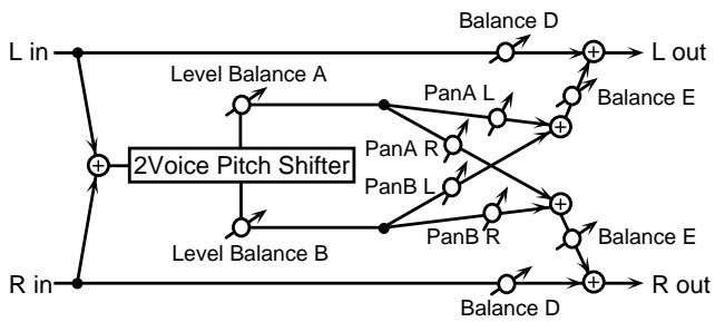
MODE (Pitch shifter mode) 1-5
Higher settings will cause the response to be slower, but the pitch will be steadier.
COARSE A (Coarse pitch A) -24--+12 #
Specify the pitch shift amount in semitones for pitch shift A. (-2 - +1 octave)
COARSE B (Coarse pitch B) -24--+12
Specify the pitch shift amount in semitones for pitch shift B. (-2 - +1 octave)
FINE A (Fine pitch A) -100-+100
Adjust the pitch shift amount in 2-cent units (1 cent = 1/100th of a semitone) for pitch shift A.
FINE B (Fine pitch B) -100--+100
Adjust the pitch shift amount in 2-cent units (1 cent = 1/100th of a semitone) for pitch shift B.
PRE DELAY A (Pre delay time A) 0.0-500 ms
Specify the time delay from the original sound until the pitch shift A sound is heard.
PRE DELAY B (Pre delay time B) 0.0-500 ms
Specify the time delay from the original sound until the pitch shift B sound is heard.
PAN A (Output pan A) L64-0-R63
Specify the stereo location of the pitch shift A sound.
A setting of L64 is far left, 0 is center, and R63 is far right.
PAN B (Output pan B) L64-0-R63
Specify the stereo location of the pitch shift B sound.
A setting of L64 is far left, 0 is center, and R63 is far right.
LVL BALANCE (Level balance) A100:OB-A0:100B
Adjust the volume balance between the pitch shift A and pitch shift B sounds.
With a setting of A100:0B only the pitch shift A sound will be output, and with a setting of A0:100B only the pitch shift B sound will be output.
BALANCE (Effect balance) D100:OE-D0:100E
Adjust the volume balance between the original sound and the pitch shift sound.
With a setting of D100:0E only the original sound will be output, and with a setting of D0:100E only the pitch shift sound will be output.
LEVEL (Output level) 0-127
Specify the output volume.
23: FB-P.SFT (Feedback pitch shifter)
This is a pitch shifter that is able to return the pitch shifted sound back to the input.
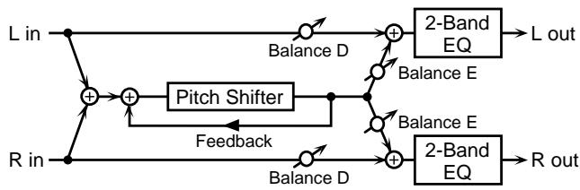
MODE (Pitch shifter mode) 1-5
Higher settings will cause the response to be slower, but the pitch will be steadier.
COARSE (Coarse pitch) -24--+12 #
Specify the pitch shift amount in semitone steps. (-2 - +1 octave)
FINE (Fine pitch) -100-+100
Adjust the pitch shift amount in 2-cent steps (1 cent = 1/100th of a semitone).
PRE DELAY (Pre delay time) 0.0-500 ms
Specify the time delay from the original sound until the pitch shift sound is heard.
FEEDBACK -98-+98%
Specify the proportion (%) of the pitch shift sound that is to be returned to the input.
Positive (+) settings will return the sound to the input with the original phase, while negative (-) settings produce an inverted phase.
PAN (Output pan) L64-0-R63
Specify the stereo location of the pitch shift sound.
A setting of L64 is far left, 0 is center, and R63 is far right.
LOW GAIN -15-+15 dB
Specify the gain (amount of boost or cut) of the low frequency range.
Positive (+) settings will emphasize (boost) the low frequency range.
HIGH GAIN -15-+15 dB
Specify the gain (amount of boost or cut) of the high frequency range.
Positive (+) settings will emphasize (boost) the high frequency range.
BALANCE (Effect balance) D100:OE-D0:100E
Specify the volume balance between the original sound and the pitch shift sound.
With a setting of D100:0E only the original sound will be output, and with a setting of D0:100E only the pitch shift sound will be output.
LEVEL (Output level) 0-127
Specify the output volume.
24: REVERB
Reverb adds reverberation to the original sound, simulating an acoustic space.
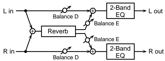
TYPE (Reverb type) Room1/Room2/Stage1/Stage2/Hall1/Hall2
Specify the type of reverb.
Room1: Short reverberation with high density
Room2: Short reverberation with low density
Stage1: Reverberation with heavy subsequent reverberation
Stage2: Reverberation with strong early reflections
Hall1: Clear reverberation
Hall2: Rich reverberation
PRE DELAY (Pre delay time) 0.0-100 ms
Specify the time delay from the original sound until the reverb is heard.
TIME (Reverb time) 0-127 #
Specify the length of reverberation.
HF DAMP
200/250/315/400/500/630/800/1000/1250/1600/2000/2500/3150/ 4000/5000/6300/8000 (200-8000 Hz), Bypass
Specify the frequency at which the high frequency portion of the reverb sound will be cut.
Lower frequency settings will cause a greater portion of the high range to be cut, producing a softer reverb sound.
If you do not want the sound to be cut, select Bypass.
LOW GAIN -15--+15 dB
Specify the gain (amount of boost or cut) of the low frequency range.
Positive (+) settings will emphasize (boost) the low frequency range.
HIGH GAIN -15-+15 dB
Specify the gain (amount of boost or cut) of the high frequency range.
Positive (+) settings will emphasize (boost) the high frequency range.
BALANCE (Effect balance) D100:OE-D0:100E
Specify the volume balance between the original sound and the reverb sound.
With a setting of D100:0E only the original sound will be output, and with a setting of D0:100E only the reverb sound will be output.
LEVEL (Output level) 0-127
Specify the output volume.
25: GATE-REVERB
Gate reverb is a type of reverb effect which cuts the reverb sound during its decay.
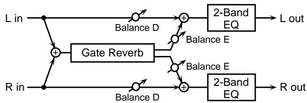
TYPE (Gatereverb type) Normal/Reverse/Sweep1/Sweep2
Specify the type of reverb.
Normal: Conventional gated reverb.
Reverse: Reverse reverb.
Sweep1: The reverb sound moves from right to left.
Sweep2: The reverb sound moves from left to right.
PRE DELAY (Pre delay time) 0.0-100 ms
Specify the time delay from the original sound until the reverb is heard.
GATE TIME 5-500 ms
Specify the length of the reverb sound.
LOW GAIN -15-+15 dB
Specify the gain (amount of boost or cut) of the low frequency range.
Positive (+) settings will emphasize (boost) the low frequency range.
HIGH GAIN -15-+15 dB
Specify the gain (amount of boost or cut) of the high frequency range.
Positive (+) settings will emphasize (boost) the high frequency range.
BALANCE (Effect balance) D100:OE-DO:100E # Specify the volume balance between the original sound and the reverb sound.
With a setting of D100:0E only the original sound will be output, and with a setting of D0:100E only the reverb sound will be output.
LEVEL (Output level) 0-127
Specify the output volume.
26: OD CHO (Overdrive Chorus)
This effect connects an overdrive and chorus in series.
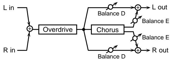
OD DRIVE 0-127 #
Specify the amount of distortion for the overdrive. The volume will change together with the amount of distortion.
OD PAN (Overdrive pan) L64-0-R63
Specify the stereo location of the overdrive sound.
A setting of L64 is far left, 0 is center, and R63 is far right.
CHO PRE DLY (Chorus pre delay time) 0.0-100 ms
This sets the interval from the time when the original sound is played until the time when the chorus sound is played.
CHO RATE (Chorus rate) 0.05-10.0 Hz
Specify the modulation frequency of the chorus sound.
CHO DEPTH (Chorus depth) 0-127
Specify the modulation depth of the chorus sound.
CHO BALANCE (Chorus balance) D100:OE-D0:100E
Specify the relative volume levels for the overdrive sound that does not pass through chorus, versus that which does. A setting of D100:0E will result in output of solely the overdrive sound, while a setting of D0:100E will cause only the overdrive sound that is passed through chorus to be output.
LEVEL (Output level) 0-127
Specify the output volume.
27: OD FL (Overdrive Flanger)
This effect connects an overdrive and a flanger in series.
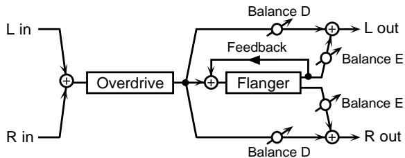
OD DRIVE 0-127 #
Specify the amount of distortion for the overdrive. The volume will change together with the amount of distortion.
OD PAN (Overdrive pan) L64-0-R63
Specify the stereo location of the overdrive sound.
A setting of L64 is far left, 0 is center, and R63 is far right.
FL PRE DLY (Flanger pre delay time) 0.0-100ms
Specify the time delay from the original sound until the flanger sound is heard.
FL RATE (Flanger rate) 0.05-10.0 Hz
Specify the modulation frequency of the flanger sound.
FL DEPTH (Flanger depth) 0-127
Specify the modulation depth of the flanger sound.
FL FEEDBACK (Flanger feedback level) -98-+98%
Specify the proportion (%) of the flanger sound that is to be returned to the input.
Positive (+) settings will return the sound to the input with the original phase, while negative (-) settings produce an inverted phase.
You can set a value from -98% to +98% , in steps of 2% . There is no feedback when the value is zero.
FL BALANCE (Flanger balance) D100:OE-D0:100E
Specify the volume balance between the overdrive sound that does not pass through the flanger and the overdrive sound that does pass through the flanger.
A setting of D100:0E will output only the overdrive sound, and a setting of D0:100E will output only the overdrive sound that is passed through the flanger.
LEVEL (Output level) 0-127
Specify the output volume.
28: OD DLY (Overdrive Delay)
This effect connects an overdrive and a delay in series.
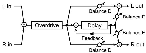
OD DRIVE 0-127 #
Specify the amount of distortion for the overdrive. The volume will change together with the amount of distortion.
OD PAN (Overdrive pan) L64-0-R63
Specify the stereo location of the overdrive sound.
A setting of L64 is far left, 0 is center, and R63 is far right.
DLY TIME (Delay time) 0.0-500 ms
Specify the time delay from the original sound until the delay sound is heard.
DLY FEEDBACK (Delay feedback level) -98-+98%
Specify the proportion (%) of the delay sound that is to be returned to the input.
Positive (+) settings will return the sound to the input with the original phase, while negative (-) settings produce an inverted phase.
You can set a value from -98% to +98% , in steps of 2% . There is no feedback when the value is zero.
DLY HF DAMP (Delay HF damp)
200/250/315/400/500/630/800/1000/1250/1600/2000/2500/3150/ 4000/5000/6300/8000 (200-8000 Hz), Bypass
Specify the frequency at which the high frequency range of the delayed sound returned to the input will be cut.
If you do not want the sound to be cut, select Bypass.
DLY BALANCE (Delay balance) D100:OE-D0:100E
Specify the volume balance between the overdrive sound that does not pass through the delay and the overdrive sound that does pass through the delay.
A setting of D100:0E will output only the overdrive sound, and a setting of D0:100E will output only the overdrive sound that is passed through the delay.
LEVEL (Output level) 0-127
Specify the output volume.
29: DS CHO (Distortion Chorus)
This effect connects distortion and chorus in series. The parameters are essentially the same as "26: OD CHO ," with the exception of the following two.
OD DRIVE DS DRIVE #
(Specify the amount of distortion.)
OD PAN DS PAN
(Specify the stereo location of the distortion sound.)
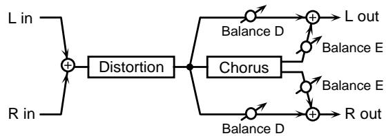
30: DS → FL (Distortion → Flanger)
This effect connects distortion and flanger in series. The parameters are essentially the same as in "27: OD FL ," with the exception of the following two.
OD DRIVE DS DRIVE #
(Specify the amount of distortion.)
OD PAN DS PAN
(Specify the stereo location of the distortion sound.)
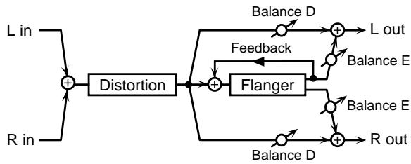
31: DS DLY (Distortion Delay)
This effect connects distortion and delay in series. The parameters are essentially the same as in "28: OD DLY ," with the exception of the following two.
OD DRIVE DS DRIVE #
(Specify the amount of distortion.)
OD PAN DS PAN
(Specify the stereo location of the distortion sound.)
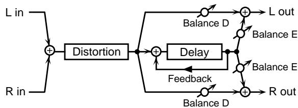
32: EH CHO (Enhancer Chorus)
This effect connects an enhancer and a chorus in series.
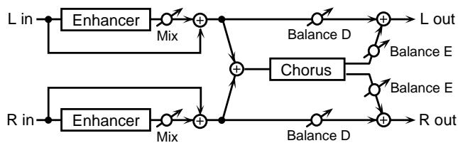
EH SENS (Enhancer sensitivity) 0-127
Specify the sensitivity of the enhancer.
EH MIX (Enhancer mix level) 0-127
Specify the volume of the overtones generated by the enhancer, relative to the original sound.
CHO PRE DLY (Chorus pre delay time) 0.0-100 ms
Specify the time delay from the original sound until the chorus sound is heard.
CHO RATE (Chorus rate) 0.05-10.0 Hz #
Specify the modulation frequency of the chorus sound.
CHO DEPTH (Chorus depth) 0-127
Specify the modulation depth of the chorus sound.
CHO BALANCE (Chorus balance) D100:OE-D0:100E
Specify the volume balance between the enhancer sound that does not pass through the chorus and the enhancer sound that does pass through the chorus.
A setting of D100:0E will output only the enhancer sound, and a setting of D0:100E will output only the enhancer sound that is passed through the chorus.
LEVEL (Output level) 0-127
Specify the output volume.
33: EH → FL (Enhancer → Flanger)
This effect connects an enhancer and a flanger in series.
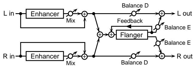
EH SENS (Enhancer sensitivity) 0-127
Specify the sensitivity of the enhancer.
EH MIX (Enhancer mix level) 0-127
Specify the volume of the overtones generated by the enhancer, relative to the original sound.
FL PRE DLY (Flanger pre delay time) 0.0-100 ms
Specify the time delay from the original sound until the flanger sound is heard.
FL RATE (Flanger rate) 0.05-10.0 Hz #
Specify the modulation frequency of the flanger sound.
FL DEPTH (Flanger depth) 0-127
Specify the modulation depth of the flanger sound.
FL FEEDBACK (Flanger feedback level) -98-+98 % Specify the proportion (%) of the flanger sound which will be returned to the input.
Positive (+) settings will return the sound to the input with the original phase, while negative (-) settings produce an inverted phase.
You can set a value from -98% to +98% , in steps of 2% . There is no feedback when the value is zero.
FL BALANCE (Flanger balance) D100:OE-DO:100E
Specify the volume balance between the enhancer sound that does not pass through the flanger and the enhancer sound that does pass through the flanger.
A setting of D100:0E will output only the enhancer sound, and a setting of D0:100E will output only the enhancer sound that is passed through the flanger.
LEVEL (Output level) 0-127
Specify the output volume.
34: EH DLY (Enhancer Delay)
This effect connects an enhancer and delay in series.
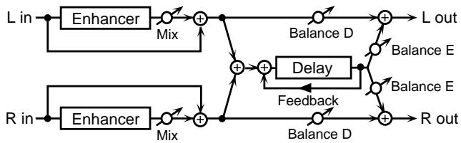
EH SENS (Enhancer sensitivity) 0-127
Specify the sensitivity of the enhancer.
EH MIX (Enhancer mix level) 0-127
Specify the volume of the overtones generated by the enhancer, relative to the original sound.
DLY TIME (Delay time) 0.0-500 ms
Specify the time delay from the original sound until the delay sound is heard.
DLY FEEDBACK (Delay feedback level) -98-+98 % #
Specify the proportion (%) of the delay sound that is to be returned to the input.
Positive (+) settings will return the sound to the input with the original phase, while negative (-) settings produce an inverted phase.
You can set a value from -98% to +98% , in steps of 2% . There is no feedback when the value is zero.
DLY HF DAMP (Delay HF damp)
200/250/315/400/500/630/800/1000/1250/1600/2000/2500/3150/ 4000/5000/6300/8000 (200-8000 Hz), Bypass
Specify the frequency at which the high frequency range of the delayed sound returned to the input will be cut.
If you do not want the sound to be cut, select Bypass.
DLY BALANCE (Delay balance) D100:OE-DO:100E
Specify the volume balance between the enhancer sound that does not pass through the delay and the enhancer sound that does pass through the delay.
A setting of D100:0E will output only the enhancer sound, and a setting of D0:100E will output only the enhancer sound that is passed through the delay.
LEVEL (Output level) 0-127
Specify the output volume.
35: CHO DLY (Chorus Delay)
This effect connects a chorus and a delay in series.
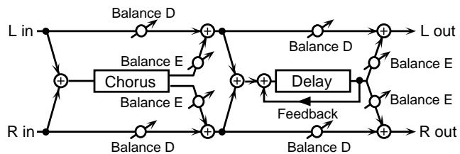
CHO PRE DELAY (Chorus pre delay time) 0.0-100 ms
Specify the time delay from the original sound until the chorus sound is heard.
CHO RATE (Chorus rate) 0.05-10.0 Hz #
Specify the modulation frequency of the chorus sound.
CHO DEPTH (Chorus depth) 0-127
Specify the modulation depth of the chorus sound.
CHO BALANCE (Chorus balance) D100:OE-D0:100E
Specify the volume balance between the original sound and the chorus sound.
With a setting of D100:0E only the original sound will be output, and with a setting of D0:100E only the chorus sound will be output.
DLY TIME (Delay time) 0.0-500 ms
Specify the time delay from the original sound until the delay sound is heard.
DLY FEEDBACK (Delay feedback level) -98-+98%
Specify the proportion (%) of the delay sound that is to be returned to the input.
Positive (+) settings will return the sound to the input with the original phase, while negative (-) settings produce an inverted phase.
You can set a value from -98% to +98% , in steps of 2% . There is no feedback when the value is zero.
DLY HF DAMP (Delay HF damp)
200/250/315/400/500/630/800/1000/1250/1600/2000/2500/3150/ 4000/5000/6300/8000 (200-8000 Hz), Bypass
Specify the frequency at which the high frequency range of the delayed sound returned to the input will be cut.
If you do not want the sound to be cut, select Bypass.
DLY BALANCE (Delay balance) D100:OE-D0:100E
Specify the volume balance between the chorus sound that passes through the delay and the chorus sound which does not pass through the delay.
With a setting of D100:0E only the chorus sound will be output, and with a setting of D0:100E only the chorus sound that passes through the delay will be output.
LEVEL (Output level) 0-127
Specify the output volume.
36: FL DLY (Flanger Delay)
This effect connects a flanger and a delay in series.
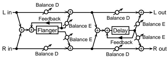
FL PRE DLY (Flanger pre delay time) 0.0-100 ms
Specify the time delay from the original sound until the flanger sound is heard.
FL RATE (Flanger rate) 0.05-10.0 Hz #
Specify the modulation frequency of the flanger sound.
FL DEPTH (Flanger depth) 0-127
Specify the modulation depth of the flanger sound.
FL FEEDBACK (Flanger feedback level) -98-+98%
Specify the proportion (%) of the flanger sound that is to be returned to the input.
Positive (+) settings will return the sound to the input with the original phase, while negative (-) settings produce an inverted phase.
You can set a value from -98% to +98% , in steps of 2% . There is no feedback when the value is zero.
FL BALANCE (Flanger balance) D100:OE-D0:100E
Specify the volume balance between the original sound and the flanger sound.
With a setting of D100:0E only the original sound will be output, and with a setting of D0:100E only the flanger sound will be output.
DLY TIME (Delay time) 0.0-500 ms
Specify the time delay from the original sound until the delay sound is heard.
DLY FEEDBACK (Delay feedback level) -98-+98%
Specify the proportion (%) of the delay sound that is to be returned to the input.
Positive (+) settings will return the sound to the input with the original phase, while negative (-) settings produce an inverted phase.
You can set a value from -98% to +98% , in steps of 2% . There is no feedback when the value is zero.
DLY HF DAMP (Delay HF damp)
200/250/315/400/500/630/800/1000/1250/1600/2000/2500/3150/ 4000/5000/6300/8000 (200-8000 Hz), Bypass
Specify the frequency at which the high frequency range of the delayed sound returned to the input will be cut.
If you do not want the sound to be cut, select Bypass.
DLY BALANCE (Delay balance) D100:OE-DO:100E
Specify the volume balance of the flanger sound that passes through the delay and the flanger sound which does not pass through the delay.
With a setting of D100:0E only the flanger sound will be output, and with a setting of D0:100E only the flanger sound that passes through the delay will be output.
LEVEL (Output level) 0-127
Specify the output volume.
37: CHO FL (Chorus Flanger)
This effect connects a chorus and flanger in series.

CHO PRE DLY (Chorus pre delay time) 0.0-100 ms
Specify the time delay from the original sound until the chorus sound is heard.
CHO RATE (Chorus rate) 0.05-10.0 Hz
Specify the modulation frequency of the chorus sound.
CHO DEPTH (Chorus depth) 0-127
Specify the modulation depth of the chorus sound.
CHO BALANCE (Chorus balance) D100:OE-D0:100E
Specify the volume balance between the original sound and the chorus sound.
With a setting of D100:0E only the original sound will be output, and with a setting of D0:100E only the chorus sound will be output.
FL PRE DLY (Flanger pre delay time) 0.0-100 ms
Specify the time delay from the original sound until the flanger sound is heard.
FL RATE (Flanger rate) 0.05-10.0 Hz #
Specify the modulation frequency of the flanger sound.
FL DEPTH (Flanger depth) 0-127
Specify the modulation depth of the flanger sound.
FL FEEDBACK (Flanger feedback level) -98-+98%
Specify the proportion (%) of the flanger sound that is to be returned to the input.
Positive (+) settings will return the sound to the input with the original phase, while negative (-) settings produce an inverted phase.
You can set a value from -98% to +98% , in steps of 2% . There is no feedback when the value is zero.
FL BALANCE (Flanger Balance) D100:OE-D0:100E
Specify the volume balance between the chorus sound that passes through the flanger and the chorus sound that does not pass through the flanger.
With a setting of D100:0E only the chorus sound will be output, and with a setting of D0:100E only the chorus that passes through the flanger sound will be output.
LEVEL (Output level) 0-127
Specify the output volume.
38:CHO/DLY (Chorus/Delay)
This effect connects a chorus and a delay in parallel. The parameters are essentially the same as "35: CHO DLY." However, Delay Balance specifies the volume balance between the original sound and the delay sound.
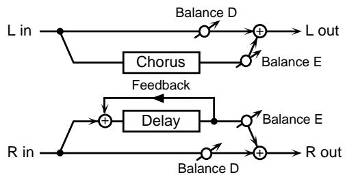
39: FL/DLY (Flanger/Delay)
This effect connects a flanger and a delay in parallel. The parameters are essentially the same as "36: FL DLY."
However, Delay Balance specifies the volume balance between the original sound and the delay sound.

40: CHO/FL (Chorus/Flanger)
This effect connects a chorus and a flanger in parallel. The parameters are essentially the same as "37:CHO FL."
However, Flanger Balance specifies the volume balance between the original sound and the flanger sound.
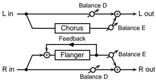
Making Chorus Settings
Here's how to adjust parameters such as modulation depth and speed for the chorus sound.
Procedure for Setting Chorus
- Select the patch for which Chorus is to be set, and press [EFFECTS] to go into Patch Edit mode.
- Use [PARAMETER] to select the CHORUS-related parameter.
For a description of the chorus parameter types, "Chorus parameters and their significance."
CHOSENDLEVEL 50
- Use [VALUE] to choose the setting value.
For the setting values, see the subsequent section, "Chorus parameters and their significance." - Repeat steps 2 to 3 to set all chorus parameters.
- Press [WRITE] to perform the Patch Write operation (p. 36).
-
After performing the Patch Write operation, you will automatically return to Play mode.
-
If you don't want to save the Patch, press [PLAY] to return to Play mode.
Chorus parameters and their significance
CHO SEND LEVEL (Chorus Send Level)
Specifies the volume of the chorus.
Increasing this setting will raise the volume.
CHORUS RATE
Specifies the modulation frequency of the chorus effect.
Higher values result in a faster modulation (cycle).
CHORUS DEPTH
Specifies the modulation depth of the chorus effect.
As this setting is increased, the modulation will become deeper.
CHORUS PRE-DELAY
Specifies the delay between when the original sound is heard and when chorusing begins.
Higher settings will make the sound more spacious.
CHORUS FEEDBACK
Adjusts the amount of chorus sound that is returned (fed back) to the input of the chorus.
Higher settings create more complex chorusing.
Making Reverb Settings
With the GR-33 you can pick one of eight types (REVERB TYPE), and then freely make your own settings to reverb amount and length. Depending on the type you select, delay (an effect that repeats a sound, sort of like a mountain echo), is also available.
Procedure for Setting Reverb
- Select the patch for which Reverb is to be set, and press [EFFECTS] to go into Patch Edit mode.
- Press [PARAMETER] to select "REVERB TYPE."
REVERB TYPE Room1
- Use [VALUE] to select the reverb type.
For the setting values, see the subsequent section, "Reverb parameters and their significance."
- Use [PARAMETER] to choose a reverb parameter that has not set.
For a description of the reverb parameter types, "Reverb parameters and their significance." - Use [VALUE] to choose the value.
- Repeat steps 4 to 5 to set all reverb parameters.
-
Press [WRITE] to perform the Patch Write operation (p. 36).
-
After performing the Patch Write operation, you will automatically return to Play mode.
- If you don't want to save the Patch, press [PLAY] to return to Play mode.
Reverb parameters and their significance
REVERB TYPE (Reverb/Delay Type)
Selects a type of reverb or delay.
Room1: Short reverb with high density
Room2: Short reverb with low density.
Stage1: Reverb with much subsequent reverberation
Stage2: Reverb with strong early reflections
Hall1: Reverb with clear reverberation.
Hall2: Reverb with rich reverberation.
Delay: Standard delay
Pan Delay: A delay effect with echoes that pan left and right.
REV SEND LEVEL (Reverb/Delay Send Level)
Specifies the volume of the reverb (or delay).
Increasing this setting will raise the volume.
REVERB TIME (Reverb/Delay Time)
When the REVERB TYPE is "Delay" or "Pan Delay" (delay), this sets the delay time. For other settings (reverb), this sets the time that the reverb will continue.
Higher settings will produce longer times.
REVERB HF DAMP (Reverb/Delay HF Damp)
Specifies the frequency above which the high-frequency content of the reverb sound will be reduced, or "damped."
Lower values cause a greater range of high frequencies to be cut, producing a softer reverb sound.
If you do not want to damp the high frequencies, set this parameter to BYPASS.
DELAY FEEDBACK
This parameter goes into effect only when REVERB TYPE is set to "Delay" or "Pan Delay." Specifies the amount of the delay effect's output to be returned — fed back – to its input. Higher values result in more repeats.
Temporarily Turning Off Effects (EFFECT BYPASS)
When you want to compare a sound with and without effect, and while you are making effect settings in the process of creating a patch, there will be times when you'll want a simple way to turn the internal Multi-effects on and off. You get this kind of convenience with the Effect Bypass.
■ Temporarily Turning Off an Effect
- In Patch Edit mode EFFECTS (effect-related settings), press [EFFECTS].
Of the onboard reverb, chorus, and multi-effects, the effect currently being edited will be switched off, and be bypassed. The three-digit display "Edit" will blink, showing that the unit is bypassed. The three-digit display "Edit" will blink, showing that the unit is bypassed.
-
Only the effect being edited will be bypassed by the Bypass function.
-
The Bypass function is available only in Patch Edit mode EFFECTS (effect-related settings).
-
Even if you use the Bypass function, the contents of the effect settings will not be affected.
-
Press [EFFECTS] once again.
The Bypass function will be defeated, and you will return to the state before you selected Bypass.
The three-digit display "Edit" will change from blinking back to steadily lit.
- Since Effect Bypass remains a temporary condition throughout, the bypass conditions are not preserved even when saving to patches or if the power is turned off. To turn off an effect in an individual patch, set REV SEND LEVEL (p. 75) and CHO SEND LEVEL (p. 74) to “0,” set MULTI-FX SW (p. 53) to “Off,” and store it in the patch.
When the Onboard Effects Don't Work
If the onboard reverb, chorus, or Multi-effects is having no effect, double-check reconfirm each of the following:
- Check whether "Edit" is blinking in the three-digit display (the Bypass function is working).
- Is the "MULTI-FX SW" (p. 53) settings set to "Off"?
- See if the "REV SEND LEVEL" (p. 75) value is adjusted to a suitable level.
- See if the "CHO SEND LEVEL" (p. 74) value is adjusted to a suitable level.
-
If the "Rev Send Level (Reverb Send Level)" function is selected, make sure that the expression pedal (p. 47) is not rocked back all the way.
-
If the "Cho Send Level (Chorus Send Level)" function is selected, make sure that the expression pedal (p. 47) is not rocked back all the way.
- Make sure that parameters such as the "LEVEL" of the effect type used by the Multi-effects are set to an appropriate value.
Chapter 7 The Arpeggiator Function
The GR-33 is equipped with an Arpeggiator function that is uniquely suited to guitar performances. When turned on, Arpeggiator takes over when a chord is strummed, and plays the chord's notes for you in simple or complex ways. The
arpeggiator can be create a basic backing using synthesizer sounds as you play the melody, and can also provide a wide variety of musical effects that have never before been possible with a guitar synthesizer.
About the Arpeggiator Function
About "Arpeggio Patterns"
Let's consider the simplest way to play an arpeggio on an actual acoustic guitar.
The left hand fingers the song's chord progression.
Meanwhile, the right hand plays a constant pattern, such as Strings 5, 4, 3, 4, 1, 3, 2, 3.
On the GR-33, the sequence of played strings ("5, 4, 3, 4..." is called an "arpeggio pattern," or sometimes simply "pattern." The GR-33 contains 50 preset arpeggio patterns. For each patch, you can select any one of the preset arpeggio patterns. When Arpeggiator is on, fingering a chord (or single note) and stroking the strings once causes the arpeggiator to play an arpeggio using synth sounds according to the patch settings that specify how the notes are to be played—ARP., TEMPO, and so on.
- If you play a string that is not part of the selected pattern—such as String 6 in the example above—or if you play a different number of strings, the GR-33 intelligently adapts the pattern to what you play. For example, it may use the played chord's lowest tone (root) as the basis for its arpeggio.
Effective Use of the Hold Function During Arpeggios
The hold effect obtained by pressing Pedal 3 while in Pedal Effect mode can be used to create a chord progression without stopping or breaking the rhythm produced by Arpeggiator.
When Arpeggiator is on, the effect of the Hold pedal is applied only to arpeggios—as opposed to its usual behavior. This means that it can hold the arpeggior's pattern playing one tone while you pluck out a melody with the other.
The GR-33 also has a latch hold that can cause arpeggios to continue to play even after the pedal is released. It will play until the pedal is pressed again.
The hold type is set by the COMMON "HOLD TYPE" parameter in Patch Edit mode.

For more detailed information and instructions about this parameter, refer to "Selecting Hold Type (HOLD TYPE)" (p. 45).
Hold Variations Available When Arpeggiator Is On
Any of the following hold variations can be selected when Arpeggiator is on.
Damper:
Pressing the pedal and playing the guitar produces an arpeggio that is held even after the string stops vibrating. If the strings are played again, the new notes are recognized by Arpeggiator and affect the held arpeggio.
Releasing the pedal ends the hold for the arpeggio—if the string has already stopped vibrating, the arpeggio stops. Use this feature when you want to change the content of arpeggios without breaking the rhythm created by Arpeggiator.
Sostenuto:
Pressing the pedal as you play while arpeggios are being produced causes the arpeggio currently being played to be held until the pedal is released. If a new string is played while the arpeggio is held, this new performance is not reflected in the arpeggio. This lets you to play guitar-sound melodies along with synth arpeggio backing.
Latch TypeA (Latch hold type A):
With an ordinary hold function, pressing the pedal starts the hold, and releasing the pedal ends it. With a latch hold, however, pressing the pedal once begins the hold, and pressing the pedal again ends it. On the GR-33, a latch hold is available only when using Arpeggiator.
When Arpeggiator is playing and Pedal 3 (HOLD) is pressed, the GR-33 holds the arpeggio being played at the moment the pedal is pressed. This is a latch hold, so the held arpeggio continues even if you release the pedal. The hold ends when you press the pedal again. As with "Sostenuto," no new notes you play affect the held arpeggio.
During the latch hold, you can use Pedal 4 (CTRL)—which normally toggles arpeggios on and off—to perform chord changes for the arpeggio to play without disrupting its rhythm. To do this, press and hold down Pedal 4 (CTRL), play the new chord, and release the pedal—Arpeggiator plays the new chord.
Latch TypeB (Latch hold type B):
The basic operation is the same as for "Latch TypeA"—the hold is maintained even if you take your foot off the pedal, and the hold is released when you press the pedal again. "Latch TypeB" is also like "Latch TypeA" in that nothing you play while the hold is on affects the held arpeggio.
The difference from "Latch TypeA" lies in what happens when the guitar is played while Pedal 4 (CTRL) is depressed—with "Latch TypeB," you can play new notes on the guitar to affect the held arpeggio, as with "Damper." However, when Pedal 4 is not held down, newly played strings do not affect the arpeggio, as with "Latch TypeA."
Changing the Sounding of Arpeggios
The GR-33's Arpeggiator function allows you to select the arpeggiated tone (HAR/ARP SELECT), the arpeggio pattern (ARP PATTERN), and the tempo (ARP TEMPO).
Turning Arpeggiator On and Off (HAR/ARP CONTROL)
Using pedal 4 (CTRL) to turn the arpeggiator on/off If you wish to turn the arpeggiator on/off while you perform, make the following settings.
- Press [COMMON] to enter Patch Edit mode.
- Use [PARAMETER] to select "CTRL PEDAL."
- Use [VALUE] to select "HAR/ARP Control."
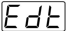
CTRL PEDAL HAR/ARP Control
-
Press [WRITE] and perform the Patch Write operation (p. 36) to save the data.
-
After Patch Write is completed, you will automatically return to Play mode.
-
If you decide not to save the data, press [PLAY] to return to Play mode.
-
Enter Pedal Effect mode.

For details on operation refer to ““Pedal Effect Mode”: What It Is, and How to Call It Up” (p. 26).
-
Alternatively, use the System mode item "S1/S2 FUNCTION" to choose "Patch Select" and return to Play mode.
-
Press pedal 4 (CTRL) to turn the arpeggiator on/off.
Turning the arpeggiator on/off in Patch Edit mode
Here's how to store the arpeggiator on/off setting in the patch.
- Press [EFFECTS] to enter Patch Edit mode.
- Use [PARAMETER] to select "HAR/ARP CONTROL."
- Use [VALUE] to turn the arpeggiator either "On" or "Off."
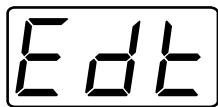
HAR/ARP CONTROL On
-
Press [WRITE] to perform the Patch Write operation (p. 36) to save the data.
-
After Patch Write is completed, you will automatically return to Play mode.
-
If you decide not to save the data, press [PLAY] to return to Play mode.
-
Alternatively, when one of the arpeggiator setting items "HAR/ARP CONTROL," "HAR/ARP SELECT," or "ARP PATTERN" are selected, you can use pedal 4 (CTRL) to turn the arpeggiator on/off.
- The arpeggiator on/off setting is independent for each patch. When you execute the Patch Write operation, the status at that time (on or off) will be reproduced the next time you recall that patch.
For each patch, either Arpeggiator or Harmonist can be selected, but not both.
Even with a patch in which these are turned off, either Arpeggiator or Harmonist is still selected. When the Arpeggiator (Harmonist) is turned on, the display of the Play mode shows "ARP" or "HAR" to indicate which one currently selected.
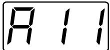
USER PATCH 1 ARP
To use Arpeggiator with a patch for which Harmonist is selected, follow the steps in the next section to set "HAR/ARP SELECT" to an Arpeggiator value such as "Arpeggio All."
- If you try to change an Arpeggiator-related setting—"HAR/ARP SELECT," "ARP PATTERN," or "ARP TEMPO"—for a patch in which Arpeggiator is turned off, Arpeggiator will be automatically turned on to let you check the new setting.
Selecting Tones to Be Arpeggiated (HAR/ARP SELECT)
The EFFECTS "HAR/ARP SELECT" (Harmony/Arpeggio select) parameter in Patch Edit mode determines for the currently selected patch whether the 1st tone, the 2nd tone, or an external sound generator is arpeggiated by Arpeggiator. Try making changes to this setting for the preset patches, and listen to the results.
Selecting Tones to Be Arpeggiated
- Select the patch for which Arpeggiator settings are to be modified, and press [EFFECTS] to go into Patch Edit mode.
- Press [PARAMETER] to select "HAR/ARP SELECT."
HAR/ARP SELECT Arpe9gio A11
- Turn [VALUE] to select the desired Arpeggiator setting.
For the Arpeggiator settings in "HAR/ARP SELECT," see the subsequent section, "Arpeggiator Settings that can be selected in HAR/ARP SELECT."
- Press [WRITE] to perform the Patch Write operation (p. 36).
To move to a different Arpeggiator parameter, use [PARAMETER] to select the desired parameter, and turn [VALUE] to change its setting.
- After performing the Patch Write operation, you will automatically return to Play mode.
- If you don't want to save the patch, press [PLAY] to return to Play mode.
Arpeggiator Settings that can be selected in HAR/ARP SELECT
Arpeggio All:
All tones from the internal sound generator and the external MIDI sound generator are arpeggiated.
Arpeggio 1st:
Only the 1st tone of the internal sound generator is arpeggiated.
Arpeggio 2nd:
Only the 2nd tone of the internal sound generator is arpeggiated.
Arpeggio 1&2:
The 1st and 2nd tones are both arpeggiated. (The external sound generator is not arpeggiated.)
Arpeggio Ext:
Only the external MIDI sound generator is arpeggiated.
Arpeggio Ext&1:
The 1st tone and the external MIDI sound generator are arpeggiated.
Arpeggio Ext&2:
The 2nd tone and the external MIDI sound generator are arpeggiated.
- You can also set the parameters that precede these—Harmony All, Harmony 1st, ..., Harmony Ext&2—but choosing one of these causes Arpeggiator to stop and selects Harmonist (p. 80). Please note that if Harmonist is chosen, it is not possible to set the “ARP PATTERN,” or “ARP TEMPO” parameters.
Selecting Arpeggio Patterns (ARP PATTERN)
The GR-33 contains 50 preset arpeggio patterns. For each patch, you can select any one of the preset arpeggio patterns.

For more detailed information about arpeggio patterns, please refer to "About "Arpeggio Patterns" (p. 76)."
Selecting Arpeggio Patterns
- Select the patch for which the Arpeggio pattern is to be modified, and press [EFFECTS] to go into Patch Edit mode.
- Press [PARAMETER] to select "ARP PATTERN."
ARP PATTERN Arpeggio 1
- Turn [VALUE] to select the desired Arpeggiator pattern.
- Press [WRITE] to perform the Patch Write operation (p. 36).
To move to a different Arpeggiator parameter, use [PARAMETER] to select the desired parameter, and turn [VALUE] to change its setting.
- After performing the Patch Write operation, you will automatically return to Play mode.
- If you don't want to save the Patch, press [PLAY] to return to Play mode.
Setting Tempo (ARP TEMPO)
You can freely vary the tempo of an arpeggio, and save the tempo in the patch. This is done using the "ARP TEMPO" (arpeggio tempo) parameter.
Setting Arpeggio Tempo
- Select the patch for which the arpeggio tempo is to be modified, and press [EFFECTS] to go into Patch Edit mode.
- Press [PARAMETER] to select "ARP TEMPO."
ARP TEMPO 120
- Turn [VALUE] to select the desired value.
The range for ARP TEMPO is from 50 to 250. As the setting is increased, the tempo speeds up.
- Press [WRITE] to perform the Patch Write operation (p. 36).
To move to a different Arpeggiator parameter, use [PARAMETER] to select the desired parameter, and turn [VALUE] to change its setting.
- After performing the Patch Write operation, you will automatically return to Play mode.
- If you don't want to save the Patch, press [PLAY] to return to Play mode.
Using the pedal to set the tempo (Tap Tempo Teach function)
You can set the arpeggiator tempo by pressing a pedal rhythmically at the desired tempo. This is called the Tap Tempo Teach function.
When you enter Patch Edit mode and make arpeggiator-related settings, Pedal 4 (CTRL) normally turns the arpeggiator on and off.
Pedal 4 (CTRL) can also be used for the Tap Tempo Teach function while you are setting the arpeggio tempo.
While the tempo is shown in the display for the Patch Edit mode EFFECTS "ARP. TEMPO" parameter, repeatedly press Pedal 4 (CTRL) at the desired tempo. The display will indicate "TAP," and the tempo will change accordingly.
When the tempo is set—when you've finished tapping—the "TAP" indicator will disappear.
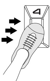
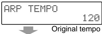
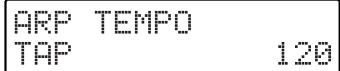
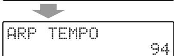
Changed
- The Tap Tempo function can also be activated using the BANK SHIFT pedal (Up side) in Pedal Effect mode when Arpeggiator is on.
- The modified tempo is a patch parameter. If desired, press the [WRITE] button to perform the Patch Write operation and save the tempo in the patch.
- Some preset patches set the value of “ARP TEMPO” to a multiple of the actual tempo in order to achieve a fine tremolo at the proper rate. In such cases, Tap Tempo may produce unexpected results.
Chapter 8 Adding Harmonies in a Specific Key (The Harmonist)
The GR-33 lets you use the TONE "TRANSPOSE" setting (p. p. 51) to shift the pitch of the 1st and 2nd tones relative to the guitar's pitch, creating an always-parallel harmony.
However, to create harmonies that are more musically useful, the differences in pitch between notes must follow the key of the song and the scale being played.
The GR-33's Harmonist function, also known as "Harmonist," creates harmonies in just this fashion. By setting the key of the melody a patch plays, Harmonist can create beautiful, appropriate harmonies by adding synth sounds to guitar sounds, or to other synth sounds.
About the Harmonist
Let's take a look at how Harmonist is put together, and compare it with the Transpose function.
The sample score shown below compares the effects of the Transpose function and Harmonist when playing the scale in the key of C major.
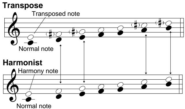
The difference in the results of the two methods is shown by the arrows in the figure.
The harmonies produced by parallel transposition may sound odd at times. The place on the scale where this problem occurs depends on the key, whether the key is major or minor, the interval between the main melodic line and the harmony, and so on.
The GR-33's Harmonist uses what it knows about the current key—which is already set in the patch—to continuously adjust the harmonic intervals between the guitar sound and synth sound, or between the 1st and 2nd tones, creating pleasing harmonies.
The GR-33's Harmonist also fully supports chord play. This means that complex chords can be created by playing a simple three-note chord, greatly reducing the chances of fingering mistakes during difficult performances.
What You Can Do with the Harmonist
Adding Synth Sounds to Guitar Sounds
The commercially available device known as "Harmonist" is a type of pitch shifter, and can only make guitar-sound harmonies for guitar sounds.
In contrast, the GR-33 Synth Harmonist lets you take the guitar sounds you normally use and make harmonies using any sounds you like.
These can be put to practical use, such as adding a marimba line to a clean guitar sound to produce a supporting harmony, or adding a rock organ to a distorted guitar to create a bluesy minor-key harmony.
And of course, you can always select a guitar tone on the GR-33 to create pure guitar harmonies.
If you wish to create a harmony between your guitar's sound and the GR-33's sounds, set the guitar/synth selector switch on the GK-2A to "MIX."
- To make all synth sounds contained in patches—from the 1st and 2nd tones to the external MIDI sound generator—harmonize with your guitar's sound, follow the steps on p. 82 to set “HAR/ARP SELECT” to “Harmony All.”
Creating Harmonies with Two Synth Sounds
You can make harmonies using only synth sounds, without hearing the guitar, by setting the guitar/synth selector switch on the GK-2A to "SYNTH."
You can produce a richer sound by using two similar tones to create harmony. It can also be quite effective to create harmonies with totally different tones—such as sax and muted trumpet—and select “CROSS TONES” with COMMON “PAN MODE” to assign these to the left and right stereo positions. You can also combine guitar sounds with the main melodic synth line by setting the switch on the GK-2A to “MIX.”
Operation
Turning the Harmonist On and Off (HAR/ARP CONTROL)
Using pedal 4 (CTRL) to turn Harmonist on/off
If you wish to turn Harmonist on/off while you perform, make the following settings.
- Press [COMMON] to enter Patch Edit mode.
- Use [PARAMETER] to select "CTRL PEDAL."
- Use [VALUE] to select "HAR/ARP Control."
CTRL PEDAL HAR/ARP Control
-
Press [WRITE] to execute the Patch Write operation (p. 36) and save the data.
-
After Patch Write is completed, you will automatically return to Play mode.
-
If you decide not to save the data, press [PLAY] to return to Play mode.
-
Enter Pedal Effect mode.

For details on operation, refer to ““Pedal Effect Mode”: What It Is, and How to Call It Up” (p. 26).
- Alternatively, use the System mode setting "S1/S2 FUNCTION" to choose "Patch Select" and return to Play mode.
- Press pedal 4 (CTRL) to turn the Harmonist on/off.
Turning the Harmonist on/off in Patch Edit mode
If you wish to store the Harmonist on/off setting in the patch, use the following procedure.
- Press [EFFECTS] to enter Patch Edit mode.
- Use [PARAMETER] to select "HAR/ARP CONTROL."
- Use [VALUE] to turn the Harmonist "On" or "Off."
HAR/ARP CONTROL On
-
Press [WRITE] to execute the Patch Write operation (p. 36) and save the data.
-
After Patch Write is completed, you will automatically return to Play mode.
- If you decide not to save the data, press [PLAY] to return to Play mode.
- Alternatively, when one of the Harmonist setting items "HAR/ARP CONTROL," "HAR/ARP SELECT," "HARMONY STYLE," "HARMONY KEY," or "HARMONY REMOTE" is selected, you can use pedal 4 (CTRL) to turn the Harmonist on/off.
- The Harmonist on/off setting is independent for each patch. When you execute the Patch Write operation, the status at that time (on or off) will be reproduced the next time you recall that patch.
For each patch, either Arpeggiator or Harmonist can be selected, but not both.
Even for a patch in which these are turned off, either Arpeggiator or Harmonist is still selected. When the Arpeggiator (Harmonist) is turned on, the display of the Play mode shows "ARP" or "HAR" to indicate which one currently selected.
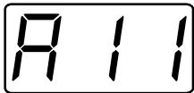
USER PATCH 1 HAR(F#m)
To use Harmonist with a patch in which Arpeggiator is selected, follow the steps in the next section to set "HAR/ARP SELECT" to a Harmonist setting such as "Harmony All."
- In patches where the harmonist is selected and turned off, changing the value of a related parameter—“HAR/ARP SELECT,” “HARMONY STYLE,” “HARMONY KEY,” or “HARMONY REMOTE”—will cause Harmonist to be automatically turned on.
Selecting Harmony Tones (HAR/ARP SELECT)
The "HAR/ARP SELECT" (Harmony/Arpeggio select) parameter for each patch determines whether the 1st tone, the 2nd tone, or an external sound generator produces the harmony.
Setting Harmony Select
- Select the patch for which Harmonist settings are to be modified, and press [EFFECTS] to go into Patch Edit mode.
- Press [PARAMETER] to select "HAR/ARP SELECT."
HAR/ARP SELECT Harmony A11
- Turn [VALUE] to select the desired Harmonist setting. For the harmonist settings in "HAR/ARP SELECT," see the subsequent section, "Harmonist Settings that can be selected in HAR/ARP SELECT."
-
Press [WRITE] to perform the Patch Write operation (p. 36). To move to a different Harmonist parameter, use [PARAMETER] to select the desired parameter, and turn [VALUE] to change its setting.
-
After performing the Patch Write operation, you will automatically return to Play mode.
- If you don't want to save the Patch, press [PLAY] to return to Play mode.
Harmonist Settings that can be selected in HAR/ARP SELECT
Harmony All:
All tones—from the internal sound generator and the external MIDI sound generator—produce harmonies.
Harmony 1st:
The 1st tone of the internal sound generator produces harmony.
Harmony 2nd:
The 2nd tone of the internal sound generator produces harmony.
Harmony 1&2:
Both the 1st and 2nd tones produce harmony.
Harmony Ext:
The external MIDI sound generator produces harmony.
Harmony Ext&1:
The 1st tone and the external MIDI sound generator produce harmony.
Harmony Ext&2:
The 2nd tone and the external MIDI sound generator produce harmony.
- You can also set the subsequent parameters—Arpeggio All, Arpeggio 1st, ..., Arpeggio Ext&2—but choosing one of these causes Harmonist to stop and selects Arpeggiator (p. 76). Please note that if Arpeggiator is chosen here, it is not possible to set the “HARMONY STYLE,” “HARMONY KEY,” or “HARMONY REMOTE” parameters.
Setting Harmonic Intervals (HARMONY STYLE)
The interval between the melody and harmony that Harmonist uses—a third, a fifth, or the like—is set with the "HARMONY STYLE" parameter.
Setting the Harmony Style
- Select the patch for which Harmony Style settings are to be modified, and press [EFFECTS] to go into Patch Edit mode.
- Press [PARAMETER] to select "HARMONY STYLE."
HARMONY STYLE +3rd
- Turn [VALUE] to select the desired harmony style interval.
An interval of -7th, -6th, -5th, -4th, -3rd, -2nd, +2nd, +3rd, +4th, +5th, +6th, +7th, or Diminish can be selected. "Diminish" produces a harmony that is always a diminished third (three semitones) from the melody, regardless of the HARMONY KEY setting. This is useful when playing in a diminished scale.
- Press [WRITE] to perform the Patch Write operation (p. 36).
To move to a different Harmonist parameter, use [PARAMETER] to select the desired parameter, and turn [VALUE] to change its setting.
- After performing the Patch Write operation, you will automatically return to Play mode.
- If you don't want to save the Patch, press [PLAY] to return to Play mode.
The various settings produce the following intervals between the melody and the harmony.
Key=C
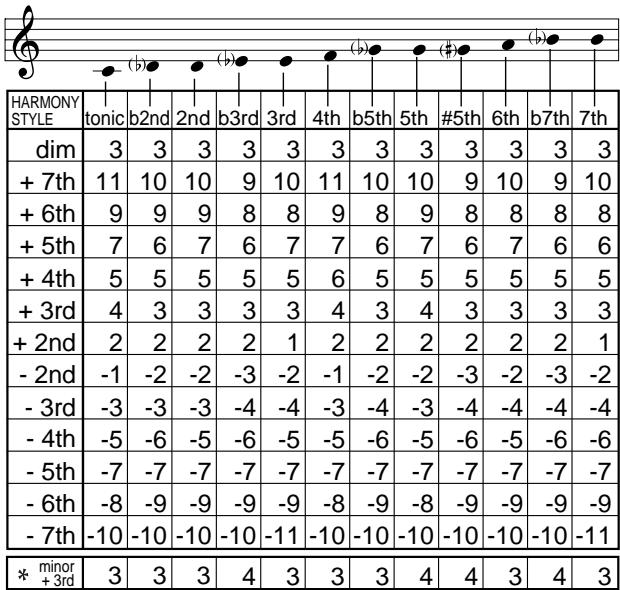
(Unit: semitone)
- When HARMONY STYLE is “+3,” and HARMONY KEY is set to “minor,” the harmony is made in a minor scale.
Setting Transpose and "HARMONY STYLE"
Transpose settings include the TONE "1ST TRANSPOSE" and "2ND TRANSPOSE" parameters, as well as COMMON "MIDI [TRANSPOSE]." Each of these is separate from "HARMONY STYLE," the Harmonist setting for the interval, and each produces its own independent effect.
This means that when using Harmonist, the transposition setting for any tone (or external sound generator) you intend to use as a harmony should normally be set to “0.” “
On the other hand, you may find it helpful to use Transpose to shift a melody or Harmonist harmony sound by octaves.
An Example:
Transposing the Harmony Down an Octave
As an example, let's use the 1st tone and 2nd tone to create a counter-melody relative to the main melody played by the guitar sound. The 1st tone will be shifted one octave down, and the 2nd tone will play a harmony a third above.
- Set the GK-2A Guitar/Synth selector switch to "MIX."
-
Select the patch you wish to use, and set up the 1st and 2nd tones.
-
For the tone settings, refer to "Creating Synth Sounds" (p. 49).
-
Press [TONE], and use [PARAMETER] to select "1ST TRANSPOSE."
- Turn [VALUE] to select " -12" (1 octave down).
1ST TRANSPOSE -12
The 1st tone will play one octave lower than the guitar sound.
-
A TRANSPOSE value can be set independently for each string. In this example, if you wish to shift all strings down by an octave, use [STRING SELECT] to make the three-digital display read "ALL," and then set the TRANSPOSE value to "-12."
-
Press [EFFECTS], and then use [PARAMETER] to choose "HAR/ARP SELECT."
- Turn [VALUE] to select "Harmony 2nd."
HAR/ARP SELECT Harmony 2nd
- Press [PARAMETER] to select "HARMONY STYLE."
- Turn [VALUE] to select “+3rd.”
HARMONY STYLE +3rd
The 2nd tone will play a harmony of a third above the guitar sound.
This produces a fat sound that sandwiches the guitar between a synth sound transposed down an octave and a synth harmony one third higher.
- The values for Transpose (TONE “1ST TRANSPOSE” and “2ND TRANSPOSE” and “MIDI [TRANSPOSE]”—36 to 0 to 24)—are displayed in semitones (one octave = 12). In contrast to this, however, the “HARMONY STYLE” values (-7th to +7th, and Diminish) are displayed in intervals (third, fifth, and so on). Remembering this will keep you from getting confused.
Setting the Key (HARMONY KEY)
The "HARMONY KEY" setting selects the key in which the patch's melody is to be played, such as C or Gm (G minor).
Setting the Harmony Key
- Select the patch for which the Harmony key setting is to be modified, and press [EFFECTS] to go into Patch Edit mode.
- Press [PARAMETER] to select "HARMONY KEY."
HARMONY KEY
- Turn [VALUE] to select the desired value.
For the possible values of HARMONY KEY, see the subsequent section, "Harmonist Setting Values that can be selected in HARMONY KEY."
- Press [WRITE] to perform the Patch Write operation (p. 36).
To move to a different Harmonist parameter, use [PARAMETER] to select the desired parameter, and turn [VALUE] to change its setting.
- After performing the Patch Write operation, you will automatically return to Play mode.
- If you don't want to save the Patch, press [PLAY] to return to Play mode.
Harmonist Setting Values that can be selected in HARMONY KEY
The values that can be chosen for HARMONY KEY are as follows.
C, C#, D, D#, E, F, F#, G, G#, A, A#, and B
Cm, C#m, Dm, D#m, Em, Fm, F#m, Gm, G#m, Am, A#m, and Bm
- If "Diminish" has been selected for the "HARMONY STYLE" setting described earlier, the harmony remains the same no matter what "HARMONY KEY" setting is selected. (The harmony is fixed at a diminished third above the melody.)
About the Key Display
In patches where Harmonist is chosen, you can check the selected key in Play mode without having to enter Patch Edit mode to access the "HARMONIST KEY" setting screen.
USER PATCH 1 HAR(C#m)
When "HARMONY STYLE" is set to "Diminish," "dim" is displayed instead of the selected key.
Changing the Key from an External Pedal or Other Device with MIDI Note Messages (HARMONY REMOTE)
The Harmonist key (HARMONY KEY) can be changed at any time during a performance by sending a MIDI note message to the GR-33 from an external MIDI device such as optional FC-200 MIDI foot controller or PK-5 MIDI pedal keyboard.
The parameter that determines whether this function is enabled or disabled for each patch is "HARMONY REMOTE" (harmony key remote).
Changing the Harmonist Key with an External MIDI Pedal
- Use a MIDI cable to connect the MIDI OUT connector on a MIDI keyboard, FC-200, or the like to the GR-33's MIDI IN connector.
- Set the MIDI send channel of the external device to the same MIDI channel as the GR-33 (p. 86).
- Select the patch with which you wish to use the remote key function, and press [EFFECTS] to enter Patch Edit mode.
- Press [PARAMETER] to select "HARMONY REMOTE."
HARMONY REMOTE Off
The current setting will be shown on the display. "On" signifies that the remote function is on, and "Off" means that it is not.
- Turn [VALUE] to select "On."
- Press [WRITE] to perform the Patch Write operation (p. 36).
To move to a different Harmonist parameter, use [PARAMETER] to select the desired parameter, and turn [VALUE] to change its setting.
- After performing the Patch Write operation, you will automatically return to Play mode.
-
If you don't want to save the Patch, press [PLAY] to return to Play mode.
-
Refer to the owner's manual for the external device, and send MIDI note messages to the GR-33.
If you are using the FC-200, press the "MODE" button on the pedal to switch to the Note mode.
No matter what mode the GR-33 is in, it will receive MIDI Note On messages and switch HARMONY KEY to the corresponding note.
- The Harmonist key remote function has no effect on a patch for which Harmonist has not been selected in “HAR/ARP SELECT,” even if “HARMONY REMOTE” is set to “On.”
- When “HARMONY REMOTE” is “On,” the GR-33’s internal sound generator does not produce sounds in response to received MIDI Note messages—Note messages are interpreted as instructions for changing keys, not for playing sounds. For this reason, “HARMONY REMOTE” should be left “Off” when not needed.
- "HARMONY REMOTE" is effective only in "Mono Mode" (p. 88).
Switching Between Major and Minor During a Performance
In Pedal Effect mode (p. 26), you can press the "Up" side of an external BANK SHIFT pedal to change the patch's "HARMONY KEY" setting (p. 84) from major to minor, or vice versa.
(for example, C# C# m C# C# m ...
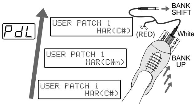
On some patches, the selected "HARMONY STYLE" setting may be "Diminish": the harmony is fixed at a diminished third above the melody, regardless of the "HARMONY KEY" setting. In such cases, the operation described above does not toggle "HARMONY KEY" between major and minor key—instead it toggles "HARMONY STYLE" between "Diminish" and "+"3rd." When you switch to "+"3rd," the key will be the key specified by "HARMONY KEY." As a result, you can toggle between diminished and a major (or minor) key.
(Example: Diminish F Diminish F..., or Diminish Gm Diminish Gm..., and so on)
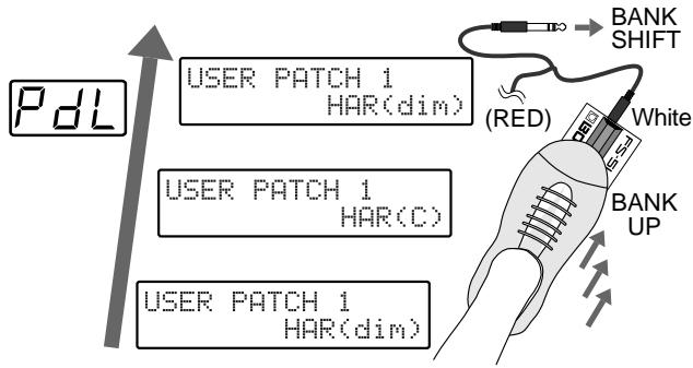
- To ensure proper reproduction of your performance when the GR-33 is used with a MIDI sequencer, the current major/minor toggled state is output from MIDI OUT.
Chapter 9 Connecting to External Sound Generators and Sequencers
Connecting an external sound generator to the GR-33 makes it possible to play sounds not included the 384 built-in tones, and to create fatter sounds by combining notes from the GR-33 and the external device.
The GR-33 can also serve as a convenient input tool for a MIDI sequencer (a device for recording performances). This chapter explains how to make such steps using external devices (and how to use MIDI functions).
About MIDI

MIDI stands for "Musical Instrument Digital Interface," a worldwide standard that enables electronic instruments and peripherals to share information about performances, sound switching, and other functions. MIDI is a standard that is shared by a wide range of instruments from different manufacturers. For instance, you could use a MIDI controller from company A to play a sound module from company B or send data to a sequencer from company C.
MIDI connectors (IN and OUT) are a standard feature of the GR-33. With MIDI, you can use the guitar to control external sound generators (such as synthesizers and samplers), or play the music you want to input into a MIDI sequencer.
Also, as we've already seen on p. 37, you can send data such as patch data to other equipment for performance or storage.
What follows is a list of some of the different types of MIDI messages that the GR-33 can handle.
"Note On messages" provide information on what string was played, and its pitch and force.
"Note Off messages" provide information on when a string stops vibrating.
"Bend messages" provide information for changing the pitch smoothly, such as when bending, sliding, or hammering.
"Program Change messages" transmit commands for switching patches.
"Control Change messages" provide information on changes in volume and effects.
"System Exclusive (SysEx) messages" provide information for exchanging patch data with external instruments.
Controlling an External MIDI Sound Device
Connecting to an External MIDI Sound Device
Follow the figure below to connect the GR-33 to an external MIDI sound device.
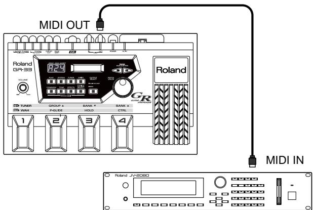
External MIDI Sound Device
Setting MIDI Channel/Bend Range (BASIC CHANNEL, BEND RANGE)
Once you've made the connections, make the required settings on the GR-33.
MIDI CHANNEL (BASIC CHANNEL)
When exchanging MIDI performance message with an external device, the GR-33 and the external device must be set to the same MIDI channel.
The channels available with MIDI range from 1 to 16. On the GR-33, you can choose to use one channel per string, for a total of six channels (Mono mode); or you can exchange information for all six strings on a single channel (Poly mode). In the case of Mono mode, you must specify the first channel (BASIC CHANNEL) of the six consecutive channels that will be used. Follow the steps described later to make the BASIC CHANNEL setting.
- For a detailed explanation of Mono mode and Poly mode, see the subsequent section, "Transmitting in Mono Mode or Poly Mode."
- When using the GR-33 in combination with a multitimbral sound module (a sound generator offering a number of performance parts) or a sequencer system (an automatic performance device), make sure the other instrument parts and channels do not overlap.
BEND RANGE
The GR-33 can even send continuous pitch changes obtained with techniques such as bending, finger vibrators, tremolo bar usage, and sliding to an external device. This is done using MIDI Pitch Bend Change messages, just as with the pitch bender on a keyboard. This means that the setting called Bend Range must be matched up on the sending and receiving instruments.
The GR-33 normally informs the external MIDI device of the Bend Range setting on the GR-33, and sends a message prompting change every time the patch is switched.
This means that the Bend Range value on the sound generator can be set automatically every time the patch is changed simply by matching the maximum Bend Range value that can be set on the external MIDI sound generator to the GR-33. (Setting Bend Range to as large a value as possible will help enable smooth pitch changes in a wider range. The settable range varies according to the receiving sound generator. For equipment having a different settable width in the bend up and down directions, match the setting to the narrowest maximum value.)
About messages that notify the external MIDI instrument of the Bend Range and prompt change
The messages used here are MIDI RPN (Registered Parameter Number) "Pitch Bend Sensitivity" messages (Control Change messages No. 100, No. 101, No. 6, and No. 38). (Sending of these messages can be stopped, if necessary. p. 98)
If you are using an external MIDI sound generator which cannot recognize such messages, manually change Bend Range on the external device to the same value on the GR-33. Refer to the Owner's Manuals for the external sound generator for information about its MIDI specifications.
Setting the Channel (and Sending Mode) and Bend Range
- Press [SYSTEM] to enter System mode.
- Press [PARAMETER] to select "BASIC CHANNEL."
BASIC CHANNEL Mono 1
- Use [VALUE] to select the setting value.
BASIC CHANNEL can be set to values of "Mono 1-11" (mono mode transmission) and "Poly 1-16" (poly mode transmission).
-
When transmitting in Mono mode, six consecutive channels are used. For this reason, it is not possible to select 12--16 as one of the first channels (BASIC CHANNEL).
-
When you finish making the setting for BASIC CHANNEL, press [PARAMETER] to choose "BEND RANGE."
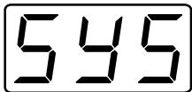
BEND RANGE
24
- Use [VALUE] to select the setting value.
BEND RANGE can be set to values of "0, 1, 2, 4, 5, 7, 12, 24."
-
Maximum the setting to the maximum value for Bend Range that can be set on the external sound generator, then press [PLAY] to return to the Play mode.
-
These are the setting items for the GR-33, and not patch settings, so there is no need to perform a Patch Write operation. The latest setting is automatically stored in memory, even after the power is switched off.
If the sending Bend Range on the GR-33 is set to "0," an effect similar to setting COMMON "CHROMATIC" (p. 42) to "Type3" is obtained for the sounds from the external MIDI sound generator.
When a multitimbral sound generator has been connected and Mono mode selected in step 3, the tones to be used are allocated to six parts on the sound generator. Also, the receiving channels are matched to the six connected channels selected on the GR-33. When in this state, you can play the external MIDI sound generator by playing the guitar own the GK-2A is mounted.
- If not sound is produced by the external MIDI sound generator, try turning the volume on the GK-2A all the up and setting the GK-2A's selector switch to "SYNTH" or "MIX."
If there's still no sound, check the sound-level settings on the sound generator, as well as the cable connections. If the setting "MIDI [PC]" described later (p. 88) has been changed, make sure that it is set to any setting other than "Off."
When Using the Volume Knob and Selector Switch on the GK-2A
When the volume on the GK-2A is adjusted, the change is sent by MIDI Control Change message No. 7 from MIDI OUT on the GR-33. (The receiving instrument should be set to recognize Control Change message No. 7.)
This makes it possible to control the volume level on the external device with the volume knob on the GK-2A. Also, when the selector switch on the GK-2A has been set to
"GUITAR," a value of zero is sent to the external sound generator on the Control Change message No. 7, and sound from the external sound generator also stops. When "MIX" or "SYNTH" is selected, values corresponding to the state of the GK-2A volume or the expression pedal are sent, and sound production is restarted.
Sending of Control Change message No. 7 can be stopped when necessary (p. 97).
Transmitting in Mono Mode or Poly Mode
Transmission in Mono or Poly mode, one or the other of which was selected at the same time as the channel in the MIDI CHANNEL setting, differs as follows.
Transmitting in Mono Mode
Number of channels used:
One channel per string is used. The number selected when specifying the channel in the System mode is taken as the start for automatically selecting six consecutive channels. (For example, when "Mono 3" is selected, the six channels from channel 3 to channel 8 are sequentially used for strings 1 through 6. This means that no channel from 12 to 16 can be selected as the starting channel when transmitting in Mono mode.)
Features:
Information on continuous pitch changes (MIDI Bend messages) can be sent independently for each string. This makes it possible to reproduce unique guitar techniques such as tremolo bar usage and harmonized bending.
Suitable usage conditions:
Mainly when using a multitimbal sound generator offering six or more parts
Transmitting in Poly Mode
Number of channels used:
A single common channel for all strings is used. The sending channel set in the System mode is used as-is.
Features:
Only a single channel is used for all guitar parts, so the number of MIDI channels used can be reduced. This enables control even for sound generators which cannot receive simultaneously on six channels.
However, it should be noted that when two or more strings are playing, Bend messages are not sent and the pitch changes at semitone intervals. This means that the pitch actually being played on the guitar cannot be reflected perfectly in the synth sound.
Suitable usage conditions:
When using an external sound generator with five or fewer parts, or when the number of MIDI channels (sound generator parts) must be reduced
- In poly mode, individual, string-specific MIDI settings are disabled. Instead, the settings for a single string are used.
Changing Patch and Other Parameters by Transmitting MIDI Messages from the GR-33 (MIDI [PC])
When the pedal or [VALUE] is used to change patches on the GR-33, a Program Change (tone change) message is sent to the external device from MIDI OUT. This can be used to change tones on the external sound generator or to change patches for guitar-sound effects.
The number of the Program Change message that is sent can be freely changed and saved to the patches on the GR-33. (At the time of purchase, Program Change numbers 1 through 128 are assigned sequentially to patches A11 through D84.)
Changing the Program Change Number Sent to the External Device During Patch Selection
- Select the patch whose setting you want to change, and press [COMMON] to enter Patch Edit mode.
- Press [PARAMETER] to select "MIDI [PC]."

3. Use the [STRING SELECT] to select "ALL" for the strings you wish to make settings.
If you wish to change settings for individual strings, refer to the following section "Selecting Separate Sounds for Different String."
![ROLAND GR-33 - Use the [STRING SELECT] to select "ALL" for the strings you wish to make settings. - 1](/content/2025/01/130734/images/507d4440cebb1055ea0560c9c480de72078bddcd1fab1d69334ff0d9bebcf604.jpg)
4. Use [VALUE] to choose the value.
The program change number can be selected from a range of Off and 1-128.
-
Press [WRITE] to perform the Patch Write operation (p. 36).
-
After performing the Patch Write operation, you will automatically return to Play mode.
- If you don't want to save the Patch, press [PLAY] to return to Play mode.
If you wish to play only the internal sound generator, select "Off" in the step 4 above. For patches that are set to "Off," you can also stop the transmission of performance data other than program changes.
Conversely, if there is a patch which should be played using only the external sound generator, just set the GR-33 patch "LAYER" setting (p. 51) to "Mute."
- It's not possible to alter the correspondences between Program Change numbers received by the GR-33 and the GR-33 patches called up by these numbers. The At the time of purchase, Program Change numbers 1 through 128 are assigned sequentially to patches A11 through D84, and this cannot be changed.
If you wish to start by matching the transmit numbers and receive numbers, access the System mode function FACTORY RESET, select "PC Number," and execute.
![ROLAND GR-33 - Use [VALUE] to choose the value. - 1](/content/2025/01/130734/images/19554745c9fb037efbba8afce86d7a63de00c788fe6114b295c8303f53e71cc6.jpg)
For more detailed information and instructions for this procedure, refer to "Re-assigning Program Change Numbers in the Order of Patches" (p. 97).
- Make changes in settings only when a MIDI loop connection is not being used.
Selecting Separate Sounds Programmed for Different Strings
It's possible to set different Program Change messages sent to an external sound generator not only for each patch, but even for each string.
In step 3 of the procedure just described, "Changing the Program Change Number Sent to the External Device During Patch Selection," set the [STRING SELECT] button to any string-number position other than "ALL" (such as 6-5, 6, 5, or the like), then use [VALUE] to make the change. This method makes it possible to change the Program Change number for just the string selected.
This also makes it simple to do unusual things like assigning a different tone to each of the six strings with the external sound generator. You can also mute out certain strings for the external sound generator by using the setting "OFF" for the desired strings.
- You can make settings for different strings for an external MIDI sound generator using the [STRING SELECT] button not only for Program Change messages, but for sending MIDI Bank Select messages as well (see the next section).
Selecting More Than 128 Tones (MIDI [CC0], MIDI [CC32])
When you use the GR-33 to select sounds on an external sound module that has a larger number of sounds than covered by the range of program change numbers (1--128), use MIDI Bank Select messages (control change numbers 0 and 32) in conjunction with the program change messages.
- The "bank" referred to here is an extended Program Change message set forth in the MIDI specification, and has absolutely nothing to do with the GR-33's bank number (the second place of the display that is, the "Bank" in "Bank Shift," "Bank Up, and "Bank Down"). Care should be taken not to confuse the two.
The GR-33 also supports this function for sending Bank Select messages.
Sending MIDI Bank Select Messages
- Select the patch whose setting you want to change, and press [COMMON] to enter Patch Edit mode.
- Use [PARAMETER] to select "MIDI [CC0]" (Control Change number 0).
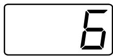
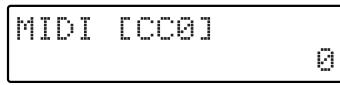
- Press [STRING SELECT] to select "ALL."
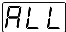
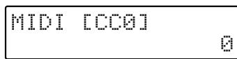
- Use [VALUE] to set the value for the tone to be called up (Off, 0 to 127).
- When you finish making the "MIDI [CC0]" setting, use [PARAMETER] to choose "MIDI [CC32]" (Control Change number 32).
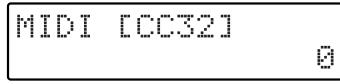
- Press [STRING SELECT] to select "ALL."
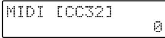
-
Use [VALUE] to set the value for the tone to be called up (Off, 0 to 127).
-
Press [WRITE] to perform the Patch Write operation (p. 36).
-
After performing the Patch Write operation, you will automatically return to Play mode.
- If you don't want to save the Patch, press [PLAY] to return to Play mode.
When you call up a patch for which the settings described above have been made, the Bank Select message and Program Change number set to the patch are used to call up a tone on the external MIDI sound generator at the same time.
If you're making a different setting for each string, then in steps 3 and 6 above, set the [STRING SELECT] button to any string-number position other than "ALL" (such as 6-5, 6, 5, ... 1), and use [VALUE] to change "MIDI [CC0]," and "MIDI [CC32]."
In Patch Edit mode, using [VALUE] to change the Program Change number or changes Control Change No. 0 or No. 32 causes MIDI messages corresponding to the selected numbers to be sent to the external MIDI sound generator as required, and the setting results appear on the external MIDI sound generator.
Also, if you move through the values quickly, such as by rotating [VALUE] quickly, the external sound generator may overflow with MIDI messages and issue a corresponding warning message (such as "MIDI Buffer Full").
Receiving MIDI Bank Select
Bank Select is the common setting for both sending and receiving. When the GR-33 is receiving, combinations of Bank Select and Program Change messages from an external device can be used to freely call up any of the 256 patches in the unit.
Preset patches (E11 through H84) can be called up with Control Change No. 0 value “1” and the appropriate Program Change message (1 through 128). Also, user patches (A11 through D84) can be called up with Control Change No. 0 value “0” and the appropriate Program Change message (1 through 128).
The receiving-side Bank Select setting correspondences for patches are also fixed and cannot be changed, even by overwriting the Bank Select and Program Change messages being sent.
A MIDI foot controller such as the FC-200 or Boss FC-50 may be connected (p. 24), using the foot controller to switch patches on the GR-33. In that case, Program Change messages and the like written to the called-up patch for the external MIDI sound generator are sent from MIDI OUT, making it possible to control all downstream devices as a group.
- Make changes in settings only when a MIDI loop connection is not being used.
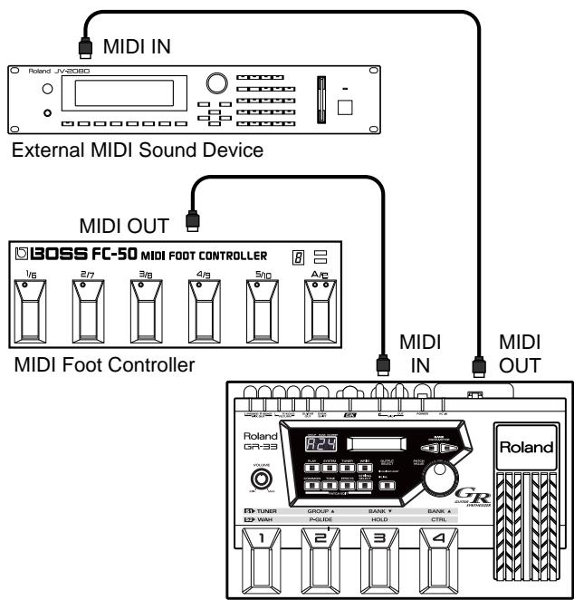
Performing the operation to sort Program Change numbers (p. 97) returns all Control Change No. 0 and No. 32 values to "0" for user patch Bank Select messages.
Applying the Arpeggiator or Harmonist Using an External Sound Device
Using Arpeggiator to Arpeggiate an External MIDI Sound Generator
You can use the GR-33's Arpeggiator to arpeggiate the sounds of an external MIDI sound generator in the same way as for the internal first and seconds tones.
When "Arpeggio All," "Arpeggio Ext," "Arpeggio Ext&1," or "Arpeggio Ext&2" is set in the EFFECTS setting "HAR/ARP SELECT"(p. 78) in the Patch Edit mode, the tones of the external MIDI sound generator are arpeggiated.
Using Harmonist to Create Harmonies with the External MIDI Sound Generator
Harmonies can be created using an external MIDI sound generator in the same way as when using the internal 1st tone and 2nd tone.
By setting the Patch Edit mode EFFECTS parameter "HAR/ARP SELECT" (p. 82) to a setting of "Harmony All,"
"Harmony Ext," "Harmony Ext&1," or "Harmony Ext&2, you can create a counter-melody using an external MIDI sound generator as well.
The Relationship Between Envelope Follow Function and MIDI Message
Patches that use the Envelope Follow function (p. 36)—in other words, patches for which “Envelope1” or “Envelope2” has been selected for the COMMON “PLAY FEEL” setting in the Patch Edit mode—send information on string amplitude (decay) during play to MIDI OUT on MIDI Control Change No. 18 (general control 3).
This is mainly used during recording and playback of performances on the GR-33 itself through a loop connection with a MIDI sequencer (p. 94), and is for recording guitar-string envelopes (decay information) along with the played sounds and playing back the performed sounds without change.
When using an external MIDI sound generator that can assign tone changes and other effects to any desired Control Change message that is received, you can also use No. 18 (sent as described above) to create changes in sounds.
Controlling External MIDI Devices with the Pedal
The GR-33's built-in pedal effects and some expansion pedal effects can also be applied to an external sound generator.
Pedal Effect 1 (WAH)
Messages about pressing and releasing the pedal are sent on Control Change No. 19. When "Modulation" has been selected as the "WAH TYPE" setting (p. 43), Control Change No. 1 is used, not No. 19.
Pedal Effect 2 (P-GLIDE)
MIDI Pitch Bend messages are used to create an effect similar to the effect for the built-in sound generator.
Pedal Effect 3 (HOLD)
This is achieved by causing issuance of MIDI Note Off messages to be paused during a hold. (A Control Change No. 64 used with keyboards is not sent. For control of the internal sound generator, however, pedal action is sent on Control Change No. 82 (general control 7).)
- When transmitting in Poly mode (p. 88), string-specific processing is impossible when the same pitch is played on different strings, so the hold effect can not be perfectly conveyed.
Pedal Effect 4 (CTRL)
Arpeggiator and Harmonist can be turned on and off in the same was as for the built-in sound generator.
About Expression Pedal Effects
When an expression pedal is used to apply some sort of effect, the pedal's action is output from MIDI OUT. This output is usually made with Control Change No. 4 (foot type), but other numbers can be used by changing the "EXP PEDAL" setting (p. 47) as follows.
"Volume": Control Change No. 7
"Pitch": MIDI Pitch Bend messages
"Modulation": Control Change No. 1
"Pan (Normal): Control Change No. 10
"Cho Send Level": Control Change No. 93
"Rev Send Level": Control Change No. 91
"Tempo&Pitch": MIDI Pitch Bend messages and Control Change No. 4
In addition to these, when a value from "CC1 to 31" or from "CC64 to 95" has been selected for the "EXP PEDAL" setting (p. 47), the Control Change message of the corresponding number follows the operation of the expression pedal and is output only from MIDI OUT. This makes it possible to use the pedal to control only the external MIDI sound generator.
- When the GR-33 receives Control Change No. 4, the synth sound of the GR-33's internal sound generator changes according to the function assigned to the expression pedal at that time. However, when a function using a specific Control Change message such as the foregoing No. 7, No. 1, or No. 91 has been assigned, No. 4 is ignored.
Transposing Performance Data for an External Sound Generator (MIDI [TRANSPOSE])
When using an external sound generator, notes in the bass (or treble) range not on the guitar can be sent by changing the COMMON setting "MIDI [TRANSPOSE]" in the Patch Edit mode to transpose the output from MIDI OUT.
Procedure for Setting MIDI [TRANSPOSE]
- Select the patch whose setting you want to change, and press [COMMON] to enter Patch Edit mode.
- Press [PARAMETER] to select "MIDI [TRANSPOE]."
![ROLAND GR-33 - Procedure for Setting MIDI [TRANSPOSE] - 1](/content/2025/01/130734/images/c0111c899a4d2f4fbef2158a55c10336638607f63301af45eaa7320c1d90e471.jpg)
MIDI [TRANSPOSE]
- Press [STRING SELECT] to select "ALL."
If you wish to change settings for individual strings, refer to "Selecting different sounds for each string" (p. 89).
![ROLAND GR-33 - Procedure for Setting MIDI [TRANSPOSE] - 2](/content/2025/01/130734/images/b41ddd1c6e90548fc0d51653f09f8a4f12c6379a1578733634f231b8f80496d9.jpg)
MIDI [TRANSPOSE]
- Use [VALUE] to choose the value.
The available range that can be selected in "MIDI [TRANSPOSE]," by semitone units, is -36 to +24.
-
Press [WRITE] to perform the Patch Write operation (p. 36).
-
After performing the Patch Write operation, you will automatically return to Play mode.
- If you don't want to save the Patch, press [PLAY] to return to Play mode.
What to do if an External Module Doesn't Produce Sound as Expected
If the external sound generator doesn't play as expected, double-check the following items.
- Do the MIDI channels for sending and receiving match? (p. 86)
- Make sure the volume level on the external sound generator has not been lowered by sending a MIDI Volume message been sent because of operation of expression pedal volume.
- Make sure the volume on the GK-2A or the expression pedal has not been turned down too low.
- Has the GK-2A select switch been set to "GUITAR"?
-
Make sure that a sound generator which cannot simultaneously receive six MIDI channels is receiving data from the GR-33 in the Mono mode (p. 88).
-
If the pitch sounds out of tune with the guitar, check “BEND RANGE.” (p. 86)
- If "BEND RANGE" has been set to "0," the pitch will change in semitone.
- When transmitting in the Poly mode, pitch changes during chord performances are in semitone (p. 86).
Using the GR-33 as an External Sequencer Input Tool
By connecting the GR-33 to a MIDI sequencer (a performance-recording and playback device), even guitarists who don't play keyboards can perform real-time recording to the sequencer.
Connecting to a Sequencer
Use MIDI cables to hook up the GR-33, sequencer (or computer running sequencer software) and multitimbral sound generator as shown in the figure.
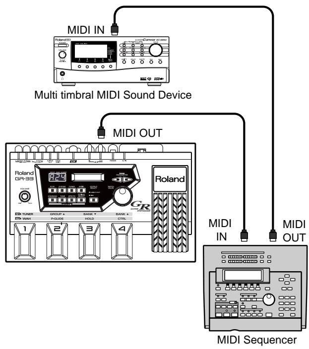
Input Procedures and Settings for Each Device
- Set the sending channel, sending mode, and bend range on the GR-33 to match the sound generator being used.

For details, refer to "Setting MIDI Channel/Bend Range (CHANNEL, BEND RANGE)" (p. 86).
- Turn on the Data Thru function (also called "Soft Thru") for MIDI IN OUT on the sequencer. (Make the setting so that MIDI message output from the GR-33 during recording is also output through MIDI OUT on the sequencer.)
- Switch on the power to the GR-33 while holding down the [PLAY] key to enable the "Local Control Off" state. When doing this, the display reads "LOCAL CONTROL OFF," and then the unit starts.

For more detailed information about Local Control Off, see the subsequent section, "About "Local Control Off."
- When everything is ready, play the guitar and make sure the external sound generator produces sound. If no problem is found, operate the external sequencer to start recording. When the recording is done, put the sequencer in the play mode and check what you've recorded.
- If you also wish to use the GR-33's sound generator in the song, also connect MIDI THRU on the external sound generator to MIDI IN on the GR-33. This makes it possible to use the GR-33 sound generator as well while listening to the performance of the external MIDI sound generator parts. (At this time, the sending MIDI channel should be selected so as not to conflict with the channel setting on the external sound generator.)
The setup just described can also be used to record tone changes and effects from the built-in and external pedals in addition to the sounds from the guitar performance. (While using Harmonist, pressing the "Up" side of an external BANK SHIFT pedal in the Pedal Effect mode toggles it between a major and minor key, and this information is also sent and recorded in the form of Control Change messages.)
- If you wish to record in a bass range that cannot be produced by the guitar, change the "MIDI [TRANSPOSE]" setting to " -12" (down one octave) or " -24" (down two octaves).
- If the sequencer you're using doesn't support simultaneous recording on more than channel, use the Poly mode for sending and recording (p. 88).
About "Local Control Off"
While the GR-33's internal sound generator and guitar controller are connected together, it is set to "Local On." In contrast to this, "Local Off" is when the GR-33's internal sound generator and guitar controller are separated, and only MIDI message from a sequencer is played. Also, guitar performance message is output only from MIDI OUT.
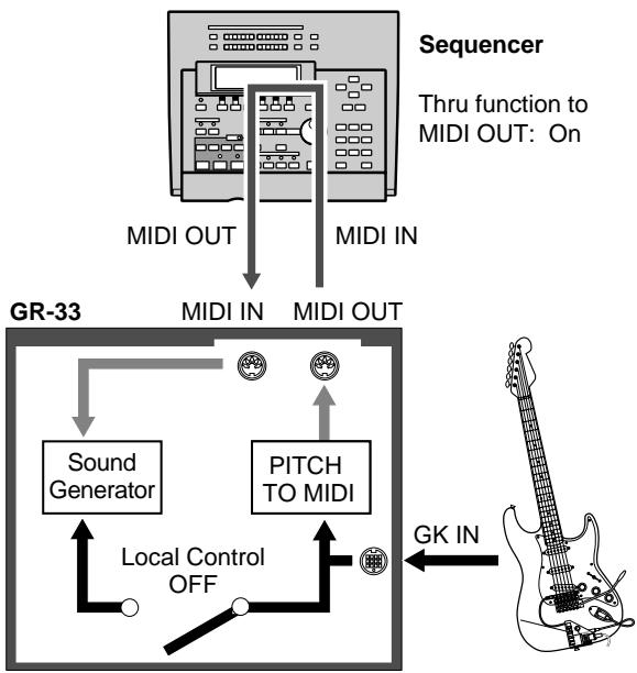
Collisions of performance data from both the guitar and the sequencer that occur at times such as when "soft thru" is enabled can be prevented by turning off local control.
To turn off local control, switch the power off and back on while holding down the [PLAY] button. (The setting for turning off local control is canceled when the power is switched on again, and is not saved in memory.)
- The detailed behavior of internal functions differs depending on whether local control is on or off. Local control is normally on, but you should be sure to switch off local control when a loop connection with external equipment is used.
Making a MIDI loop connection with local control remaining on may result in problems or faulty operation, such as failure to recognize switch operations.
- Set MIDI [PC], MIDI [CC0], and MIDI [CC32] only when a MIDI loop connection is not being used.
Creating Realistic Plucked String Instrument Sounds (Data)
Using the GR-33 to input parts for guitars and similar string instruments, including harps, koto, and others, makes it possible to achieve voicing and an expressive feeling of dispersions for separately plucked strings that cannot be reproduced with keyboard input. When doing this, however, attention should be given to the following points.
Make sure that no Quantize function (a function which forces data with loose input timing to conform to precise timing as eighth notes, sixteenth notes, or the like) has been enabled for input-data timing on the sequencer.
- When performing post-recording operation on the sequencer to shift the position of data, make sure that Bend messages are also shifted along with Note messages, so as not to destroy the correspondences between the two types of messages.
Also, those special changes in pitch that can only be produced by a guitar synthesizer (such as using the tremolo bar and harmonized bending) can also be input to the sequencer and played by means of transmission in the Mono mode, which uses one MIDI channel for each string.
Recording Arpeggiator and Harmonist Performances
Recording Arpeggiator Effects on a Sequencer
Example 1:
Arpeggiate the notes of the external MIDI sound generator, and record the results
Set the EFFECTS "HAR/ARP SELECT" setting in the Patch Edit mode to "Arpeggio Ext," then take the steps 1, 2 and 4 of "Input Procedures and Settings for Each Device" on p. 93.
(Pleases don't take step 3.) After taking step 4, play the guitar and make sure that the external MIDI sound generator is arpeggiated. Then, go to step 5 to record it.
Example 2:
Arpeggiate the GR-33's first and second tones, and record the results
Set the EFFECTS "HAR/ARP SELECT" setting in the Patch Edit mode to "Arpeggio 1st," "Arpeggio 2nd," or "Arpeggio 1&2," and carry out recording. (Arpeggios are played while recording, but only the original guitar-performance information—and not arpeggio information itself—is recorded on the sequencer.) If the same patch is used during playback, performance information is received from MIDI IN and the GR-33 rebuilds the arpeggios.
-
The setting "Arpeggio All" is not suitable for "HAR/ARP SELECT" when a sequencer and the GR-33 are connected by a MIDI cable (local control off).
-
As in Example 1 above, it is perfectly all right to record the arpeggios themselves with "Arpeggio Ext," then return this data unchanged from MIDI OUT on the sequencer (to a patch for which first and second tone arpeggios are off) to re-create the arpeggios. However, this method cannot be used to recreate performance where both tones were played but only the first tone was arpegiated.
- When using transmission in the Poly mode (p. 88), only the method described for Example 1 can be used to recording and playback.
■ Recording Harmonist Effects on a Sequencer
Example 1:
Make the first tone the melody and the second tone the harmony (or vice versa), and record the results
Set the EFFECTS "HAR/ARP SELECT" setting in the Patch Edit mode to "Harmony 2nd" (or "Harmony 1st"), and while in the same state as step 4 of "Input Procedures and Settings for Each Device" on p. 93, play the guitar and make sure the desired harmony is obtained. After that, continue from step 5 to record. The same harmony created when recording can be reproduced by using the same patch during playback.
- The Harmony feature is not available for playback in Poly mode. Use Mono mode.
Example 2:
Make the notes from the external MIDI sound generator the melody and the first and second tones the harmony, and record the results
Set the EFFECTS "HAR/ARP SELECT" setting in the Patch Edit mode to "Harmony 1&2," carry out recording in the same way as for Example 1, and play back the performance using the same patch. Make sure that the external sound generator and the GR-33 are set to the same MIDI channel at this time.
Reducing the Size of a MIDI Pitch Bend Message
With the guitar, the finger vibrato technique can be used to produce organic vibratos with amplitude and speed that can be freely varied—something that's very hard to do with a keyboard.
When creating sequencer data, the GR-33 records such finger vibratos, glissandos, and tremolo bar usage as MIDI Pitch Bend messages. As a result of this, the MIDI performance message that is output contains a large number of Pitch Bend messages. In some cases, however, these Pitch Bend messages can greatly inflate the amount of data and exceed the sequencer's memory capacity.
The Bend Data Thin function is available to keep this to a minimum.
The amount of Pitch Bend messages that are sent can be reduced by using the Bend Data Thin function. Although the smoothness of pitch changes deteriorates, this can reduce the amount of MIDI data.
■ Calling Up the Bend Data Thin Function
- Press [SYSTEM] to enter System mode.
- Press [PARAMETER] to select "BEND DATA THIN."
BEND DATA THIN Off
- Use [VALUE] to select "On."
-
Press [PLAY] to return to Play mode.
-
This is the setting items for the GR-33 (System mode), and not patch settings, so there is no need to perform a Patch Write operation. The latest setting is automatically stored in memory, even after the power is switched off.
This results in a reduced amount of pitch bend data transmissions until BEND DATA THIN is set to "Off" again. (While this function is active, the smoothness of pitch changes for the internal sound generator is also restricted.)
Practical Use of MIDI Channels
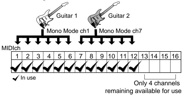
Transmitting in Mono Mode
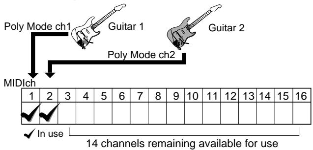
Transmitting in Poly Mode
A single MIDI system has 16 channels, and ordinarily 16 instrument parts can exist. With a guitar synthesizer,
however, each of the six strings takes up one channel.
This means that, for instance, two-part input with the guitar synth to an ensemble from a 16-part external multitimbral sound generator would use up 12 channels.
In cases like this, set the System mode setting "BASIC
CHANNEL" (p. 86) to "Poly 1" to "Poly 16" and send input to the sequencer with Poly mode sending. This lets you proceed with recording while using up only one channel per part, as with a keyboard instrument.
One drawback of transmitting in Poly mode is that it is not possible to send Pitch Bend messages for bending, sliding, vibratos, and the like when playing chords, but this mode can help in economical use of channels and parts when used judiciously separately from Mono mode input while giving consideration to the tones to be used and to single-note playing.
What to do When You Have Difficulty Sequencing
Double-check the MIDI cable connections (OUT IN, p. 93) and the setting for local control (on or off—p. 94).
When performing playback, be sure to check the MIDI channel and Bend Range settings (p. 86).
Be sure that the transmitting modes (Mono or Poly) match up. If only the sound for one string is heard during playback, you may be sending performance data to created with transmission in Mono mode a non-multitimbral sound generator.
If MIDI cannot be sent and recording is impossible for only a particular string, use the [STRING SELECT] button to set the COMMON "MIDI [PC]" setting in the Patch Edit mode to the string's number, and make sure that the setting is not "Off." (p. 88)
During transmission in Poly mode, pitch changes for chord play are in semitone steps. If continuous change in pitch is needed, use single-note playing or transmission in MIDI Mono mode.
If MIDI Bend Range is set to "1" or "2," unpleasant retriggering of sounds may occur frequently during a performance with continuous changes in pitch through bending or the like. When using the same Bend Range setting for both sending and receiving, make the value as large as possible. (p. 86)
To achieve faster sound generation and smooth pitch changes, the GR-33 transmits pitch as a combination of Note messages and Pitch bend messages. This means that if the sequencer's microscope (event list) screen shows only Note messages, what appears on-screen may differ from what is actually performed. If continuous pitch change is not required, you can create data that is displayed more faithfully by setting the sending Bend Range to "0" (p. 86).
Chapter 10 Other Convenient Functions
Re-assigning Program Change Numbers in the Order of Patches
If you have repeatedly changed the original settings of patches and re-written them to different memory locations, or have otherwise reordered the patches, the Program Change numbers “(MIDI [PC])” assigned to the patches no longer correspond to their actual order.
If you want the fixed reception program change numbers to once again correspond to the patch numbers starting at the first patch, use the following procedure to reassign the transmission program change numbers (to the factory settings) starting at the first patch.
- Please note that performing this operation causes all prior "MIDI [PC]" settings for the patches to be lost.
Re-assigning Program Change Numbers in the Order of Patches
- Press [SYSTEM] to enter System mode.
- Press [PARAMETER] to select "FACTORY RESET."
FACTORY RESET PC Number
- Turn [VALUE] to select "PC Number."
- Press [WRITE].
The message "Sure ?" appears, asking you to confirm that you want to perform the Factory Reset operation.
Sure? Press WRITE
- To perform the operation, press [WRITE] again.
"Now Writing..." appears in the display. In a moment, the GR-33 automatically returns to Play mode, completing the factory Reset.
The patches' Program Change numbers are re-assigned in sequence starting from the first patch (1, 2, 3,..., 127, 128). (All Control Change No. 0 (MIDI[CC0]) and No. 32 (MIDI[CC32]) values are returned to "0" for the sending of Bank Select messages for user patches.)
To cancel the operation, press any button other than [WRITE].
Terminating Transmission of the MIDI Controller No. 7 (Volume)
Control Change No. 7 is used not only for sending changes from the GK-2A's volume knob, but also for sending data from its "SYNTH - MIX - GUITAR" selector switch. You may occasionally encounter a MIDI-capable effects processor that cannot be set to ignore Control Change No. 7 volume control messages.
If this occurs, it will require your attention, because when the GR-33 has been connected via MIDI cables to an external effects processor—for the processing of guitar sounds and
MIDI control of the external effects—setting the selector switch on the GK-2A to “GUITAR” may mute the guitar sound, not just the synth sound.
When using the GR-33 in combination with a processor that cannot block out Control Change No. 7 messages, follow the steps below to prevent the GR-33 from sending this type of data.
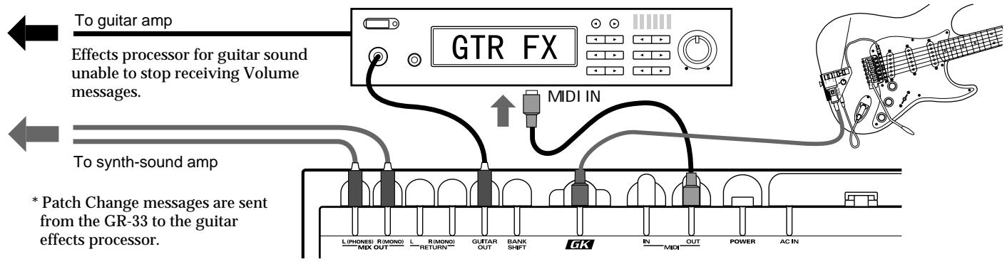
Terminating Transmission of the MIDI Controller No. 7
- Press [SYSTEM] to enter System mode.
- Press [PARAMETER] to select "VOL SEND SW."
VOL SEND SW
On
- Turn [VALUE] to select "Off."
-
Press [PLAY] to return to Play mode.
-
This is a system-wide setting, and not a patch setting, so there is no need to perform a patch write operation. The setting is automatically stored in memory even after the power is switched off.
This stops the transmission of Control Change No. 7 from MIDI OUT, eliminating the problem described above.
- This also terminates transmission of Control Change No. 7 messages for other volume-related control, so this setting should not used except when necessary. Please note that once transmission has been disabled, it remains so until you switch the setting back to "On" or restore system-related settings to their default values by performing a Factory Reset (p. 16).
Terminating Transmission of the Bend Range Request Message
The GR-33 informs any external MIDI device of the GR-33's current Bend Range setting each time a new patch is selected.
The messages used here are MIDI RPN (Registered Parameter Number) "Pitch Bend Sensitivity" messages—that is, Control Change messages No. 100, No. 101, No. 6, and No. 38.
If it is necessary for some reason to stop the transmission of these messages—such as when you wish to reduce the number of messages sent to a sequencer as you change patches on the GR-33—follow the steps below to turn off this function.
- Press [SYSTEM] to enter System mode.
- Press [PARAMETER] to select "BENDReq SW."
BEND REQ SW
On
- Turn [VALUE] to select "Off."
-
Press [PLAY] to return to Play mode.
-
This is a system-wide setting, and not a patch setting, so there is no need to perform a Patch Write operation. The setting is automatically stored in memory, even after the power is switched off.
Once you've done this, no Bend Range Request messages (MIDI Pitch Bend Sensitivity) are sent when changing patches. - Please note that once transmission has been disabled, it remains so until you return the setting to "On" or restore system-related settings to their default values by performing a Factory Reset (p. 16).
Chapter 11 Appendices
Troubleshooting
During Normal Play with Just the GR-33
No synth sounds are heard when the guitar is played
- If the unit's volume knob turned down too low?
Adjust the volume to an appropriate level. - Is the volume on the GK-2A turned down too low? Is the GK-2A's selector switch set to GUITAR?
Set the switch to SYNTH or MIX, and adjust the volume to an appropriate level. - Has the expression pedal assigned with the Volume function been returned to its raised position?
Depress the expression pedal. - Has neither the first nor second tone been selected for the Layer setting?
Assign the first (or second) tone to each of the strings (p. 51). - Is the "PACK LEVEL" setting too low?
Adjust the volume to an appropriate level (p. 38).
The pitch stays the same even when the Master Tune setting is changed.
- The only sounds that immediately change in pitch when the GR-33's Master Tune setting is changed are synth sounds controlled by an external MIDI instrument. Except when the patch "CHROMATIC" setting is set to a value from "Type1" to "Type3," synth sounds controlled by the guitar follow the guitar's actual pitch, regardless of the Master Tune setting.
After making the Master Tune setting (p. 18), use the built-in tuner to retune the guitar (p. 18) and ensure that all pitches (including the guitar) are in tune.
The Layer setting is correct, but one tone is not heard
- Is "1:2 BALANCE" (p. 52) set too much to the first tone or the second tone?
Adjust the setting to obtain a suitable balance. - Has the expression pedal assigned with tone balance been depressed (or returned to its raised position)?
Try operating the expression pedal.
The volume fluctuates from one string to another
- Are the "PickUP SENS" settings correct for each string?
Adjust the settings as required (p. 17).
Pitch doesn't rise when using Pitch Glide (or the expression pedal Pitch function)
- Functions that vary pitch continuously may experience a limited range of change during rising pitch due to the tone or register.
If a limitation is encountered, use with a narrower width of change (p. 44).
The sound change produced by an expression pedal varies from one tone to another
- For some of the 384 tones, the way the effect is applied varies subtly from the usual case when the Brightness or Wah-Wah function is assigned.
Actually assign the function and check in advance how the effect is applied (p. 47).
The way modulation is applied varies from one tone to another when using the unit's pedal effect or expression pedals
Each tone has an independent setting for the speed of undulations in pitch when using modulation.
Check the undulations in advance and choose a tone with an undulation speed that matches the song.
- The "Modulation" setting for the pedal effect (WAH) also has an independent setting in effect (undulation) depth for each tone.
Check the depth of the effect choose a tone with a depth that matches the song.
One tone is not heard when the expression pedal is used to change the tone's volume balance
-
Is the TONE "LAYER" setting set so that only the first or the second tone (but not both) is played?
Change the setting so that the first and second tones are both played (p. 51). -
Is the TONE "1:2 BALANCE" setting (p. 52) set to "50" or "-50"?
Change the setting to a value closer to "0" and check operation.
The built-in effects don't work
Is the EFFECTS setting item "REV SEND LEVEL" (p. 75), "CHO SEND LEVEL" (p. 74) set to "0," or "MULTI-FX SW" (p. 53) set to "Off"?
Select a type other than "Off."
- Are the "REV SEND LEVEL," "CHO SEND LEVEL," and volume-related Multi-effect parameters set to appropriate values?
Set them to appropriate values.
- Is the three-digit display blinking "Edit" to indicate that the unit is in EFFECT BYPASS mode?
Press [EFFECTS] to release the Bypass function (p. 75).
- The GR-33's built-in effects are exclusively for use with the internal synth sounds. They are not applied to the sounds of the guitar itself.
You can apply external effects for the guitar to only the guitar sounds by using the GUITAR OUT jack. (If you wish to use a single amp for both the guitar and synth sounds, you should also use the GUITAR RETURN jack as well.) (p. 15)
- If the "Cho Send Level (Chorus Send Level)" or "Rev Send Level (Reverb Send Level)" function is selected, make sure that the expression pedal (p. 47) is not rocked back all the way.
Depress the expression pedal.
The pitch of the synth sounds doesn't change in the same way as the pitch of the guitar sounds
- Some tones (such as percussion instruments and effect sounds) show different changes in pitch than with the guitar. This is not a defect.
- If Harmonist is on, scale changes for synth sounds are different from the guitar when “HAR/ARP SELECT” (p. 82) is set to “Harmony All” or “Harmony 1&2.”
Noise with subtle undulations is hear in extremely high registers
- This is a phenomenon peculiar to digital sound generators known as "aliasing noise." It may be audible when using the slide technique or the Pitch Shift function, but it is not a defect. The GR-33 is designed to minimize such noise during guitar play.
Pitch doesn't change smoothly
- Is COMMON “CHROMATIC” set to a value from “Type1” to “Type3”?
Set CHROMATIC to "Off" for patches that require continuous changes in pitch (p. 42). - Is the Bend Data Thin function (p. 95) in use? Using this function may result in a slight loss of smoothness when pitch changes, even during normal play.
Do not use the Bend Data Thin function when it is not needed.
"Battery Low!" appears in the display when the power is switched on
- This is a warning that means that the internal battery which maintains user patch and system setting data is almost dead. If this message appears, data may be lost is the battery is not replaced quickly.
Contact servicing by your dealer or qualified Roland service personnel.
When Changing Patch Settings
The display suddenly starts flashing
- In a parameter where the [STRING SELECT] button is valid and you select "ALL" (all strings) or "5-6" (strings 5 and 6), the blinking display indicates that the current settings differ between strings.
- During EFFECTS editing, a blinking "Edit" indicates that the bypass function is ON.
The sound doesn't vary when the settings are changed
- the GR-33's Attack, Release, and Brightness settings are intended to adjust the original data belonging to each tone. This means that the range of change differs according to the tone, and some tones may not show much of a change.
- Is the setting being changed one of the seven settings that can be made independently for each string (see the following item), and is the setting affecting only a particular string?
Use the [STRING SELECT] button to set it to "ALL." (p. 35)
Settings cannot be made independently for individual strings
- Is the setting one that cannot be made for individual strings?
→ The seven settings that can be made independently for each of the strings using the [STRING SELECT] button are TONE "Layer," "1ST TRANSPOSE," and "2ND TRANSPOSE," COMMON "MIDI [PC]," "MIDI [CC0]," "MIDI [CC32]" and "MIDI [TRANSPOSE]."
When Playing the GR-33 sound generator with a MIDI Keyboard or Other Instrument
No sound
- Do the MIDI channels for sending and receiving match?
Make sure the MIDI channels match (p. 86).
The P-GLIDE and HOLD pedal effects don't work
- The Hold and Pitch Glide functions cannot be used when play is controlled by MIDI messages from an external instrument (such as a keyboard).
Use the controls on the external instrument to apply pitch bending and holds.
Single notes are sounded when MIDI messages are sent from the external instrument, but messages such as Program Change are not received
- Are MIDI messages being sent to the five channels other than the first channel specified by the SYSTEM "BASIC CHANNEL" setting? MIDI messages other than Note messages and Bend messages must be sent to the first channel.
Be sure to send data from the external instrument to the first matching channel.
When Sending Performance Data from the GR-33 to an External MIDI Device (sound generator or Sequencer)
No sound from the external sound generator
- Do the MIDI channels for sending and receiving match?
Make sure the MIDI channels match (p. 86). - The volume level of the external sound generator may have been lowered by a MIDI Volume message (Control Change No. 7) sent from the GR-33.
Raise the volume on the GK-2A. - Make sure the volume on the GK-2A or the expression pedal has not been turned down too low.
Use the controls to increase the volume. - The sending of Note messages and the like also stops for patches for which COMMON "MIDI[PC]" is set to "Off."
Change the setting to a value from "1" to "128." (p. 88)
The external sound generator plays only one string (some strings can't be heard)
- Is the GR-33 using the Mono mode to send data to a sound generator which cannot simultaneously receive data on six MIDI channels?
For such sound generators, send data in the Poly mode (p. 88).
Notes in a bass register not on the guitar cannot be played
Output from MIDI OUT can be transposed as desired by changing the COMMON "MIDI[TRANSPOSE]" setting (p. 92).
The pitch is wrong (out of tune with the guitar)
- Is MIDI Bend Range the same for both sending and receiving?
If the pitch is off, adjust the Bend Range setting (p. 86).
Pitch doesn't change smoothly
- Is data being sent in the Poly mode? When transmitting in the Poly mode, pitch changes during chord performances are in semitone steps (p. 88).
Play with single notes, or use the Mono mode to send data.
Is the Bend Data Thin function (p. 95) in use?
Do not use the Bend Data Thin function when it is not needed.
Is SYSTEM "BEND RANGE" set to "1" or "2"?
When matching with sending and receiving, use as large a value as possible (p. 86). - If SYSTEM "BEND RANGE" has been set to "0," the pitch will change in semitone.
Change the setting to a preferable value (p. 86).
The Note messages input to the sequencer don't look like the scale that is actually played
- To start playing sounds rapidly and achieve smooth changes in pitch, the GR-33 transmits pitch as a combination of Note messages and Pitch Bend messages. This means that if only the Note messages are examined on the sequencer's microscope (event list) screen, the on-screen information may differ from what is actually performed.
If continuous pitch change is not required, you can create data that is displayed more faithfully by setting the sending Bend Range to "0." (p. 88)
Others
The volume level of the instrument connected to RETURN jack is too low.
- Could you be using a connection cable that contains a resistor?
Use a connection cable that does not contain a resistor.
Error Messages
Battery Low!
Cause: The internal backup battery (the battery which maintains the data in the user memory) is running down.
Solution: Contact your dealer or a nearby Roland service center to have the battery replaced.
Memory Damaged! Press WRITE
Cause: The contents of internal memory has been lost due to the backup battery having run down or to some malfunction.
Solution: Press [WRITE] to execute Factory Reset. If this does not resolve the problem, contact a nearby Roland service center.
MIDI Off Line!
Cause: There is a problem with the MIDI cable connection.
Solution: Check that the MIDI cable has not been disconnected or broken.
MIDI Buffer Full!
Cause: More MIDI data was received at once than could be handled by the GR-33.
Solution: Reduce the amount of MIDI data that is being received by the GR-33.
Wrong Address!
Cause: The System Exclusive address value that was received is incorrect.
Solution: Correct the address value.
Checksum Error!
Cause: The System Exclusive checksum value that was received is incorrect.
Solution: Correct the checksum value.
Roland Exclusive Messages
1. Data Format for Exclusive Messages
Roland's MIDI implementation uses the following data format for all Exclusive messages (type IV):
| Byte | Description |
| F0H | Exclusive Status |
| 41H | Manufacturer ID (Roland) |
| DEV | Device ID |
| MDL | Model ID |
| CMD | Command ID |
| [BODY] | Main data |
| F7H | End of exclusive |
-MIDI status:FOH,F7H
An Exclusive message must be flanked by a pair of status codes, starting with a Manufacturer ID immediately after F0H (MIDI version 1.0).
Manufacturer ID: 41H
The Manufacturer ID identifies the manufacturer of a MIDI instrument that sends an Exclusive message. Value 41H represents Roland's Manufacturer ID.
Device ID: DEV
The Device ID contains a unique value that identifies individual devices in the implementation of several MIDI instruments. It is usually set to 00H-0FH, a value smaller by one than that of a basic channel, but value 00H-1FH may be used for a device with several basic channels.
- Model ID: MDL
The Model ID contains a value that identifies one model from another. Different models, however, may share an identical Model ID if they handle similar data.
The Model ID format may contain 00H in one or more places to provide an extended data field. The following are examples of valid Model IDs, each representing a unique model:
01H
02H
03H
00H, 01H
00H, 02H
00H, 00H, 01H
Command ID:CMD
The Command ID indicates the function of an Exclusive message. The Command ID format may contain 00H in one or more places to provide an extended data field. The following are examples of valid Command IDs, each representing a unique function:
01H
02H
03H
00H, 01H
00H, 02H
00H, 00H, 01H
- Main data: BODY
This field contains a message to be exchanged across an interface. The exact data size and content will vary with the Model ID and Command ID.
2. Address-mapped Data Transfer
Address mapping is a technique for transferring messages conforming to the data format given in Section 1. It assigns a series of memory-resident records—waveform and tone data, switch status, and parameters, for example, to specific locations in a machine-dependent address space, thereby allowing access to data residing at the address a message specifies.
Address-mapped data transfer is therefore independent of models and data categories. This technique allows use of two different transfer procedures: one-way transfer and handshake transfer.
One-way transfer procedure (See Section 3 for details.)
This procedure is suited to the transfer of a small amount of data. It sends out an Exclusive message completely independent of the receiving device's status.
Connection Diagram
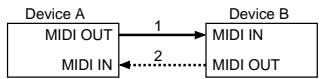
Connection at point 2 is essential for "Request data" procedures. (See Section 3.)
- Handshake-transfer procedure (This device does not use this procedure)
This procedure initiates a predetermined transfer sequence (handshaking) across the interface before data transfer takes place. Handshaking ensures that reliability and transfer speed are high enough to handle a large amount of data.
Connection Diagram
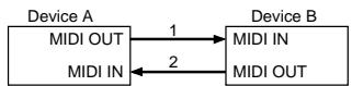
Connection at points 1 and 2 is essential.
Notes on the above procedures
- There are separate Command IDs for different transfer procedures.
- Devices A and B cannot exchange data unless they use the same transfer procedure, share identical Device ID and Model ID, and are ready for communication.
3. One-way Transfer Procedure
This procedure sends out data until it has all been sent and is used when the messages are so short that answerbacks need not be checked.
For longer messages, however, the receiving device must acquire each message in time with the transfer sequence, which inserts 20 milliseconds intervals.
Types of Messages
| Message | Command ID |
| Request data 1 | RQ1 (11H) |
| Data set 1 | DT1 (12H) |
-Request data #1: RQ1 (11H)
This message is sent out when there is a need to acquire data from a device at the other end of the interface. It contains data for the address and size that specify designation and length, respectively, of data required.
On receiving an RQ1 message, the remote device checks its memory for the data address and size that satisfy the request.
If it finds them and is ready for communication, the device will transmit a "Data set 1 (DT1)" message, which contains the requested data. Otherwise, the device won't send out anything.
| Byte | Description |
| F0H | Exclusive Status |
| 41H | Manufacturer ID (Roland) |
| DEV | Device ID |
| MDL | Model ID |
| 11H | Command ID |
| aaH | Address MSB |
| | | | |
| | | | |
| LSB | |
| ssH | Size MSB |
| | | | |
| | | | |
| LSB | |
| sum | Check sum |
| F7H | End of exclusive |
- The size of the requested data does not indicate the number of bytes that will make up a DT1 message, but represents the address fields where the requested data resides.
- Some models are subject to limitations in data format used for a single transaction. Requested data, for example, may have a limit in length or must be divided into predetermined address fields before it is exchanged across the interface.
- The same number of bytes comprises address and size data, which, however, vary with the Model ID.
- The error-checking process uses a checksum that provides a bit pattern where the last 7 bits are zero when values for an address, size, and that checksum are summed.
- Data set 1: DT1 (12H)
This message corresponds to the actual data transfer process.
Because every byte in the data is assigned a unique address, a DT1 message can convey the starting address of one or more bits of data as well as a series of data formatted in an address-dependent order.
The MIDI standards inhibit non real-time messages from interrupting an Exclusive one. This fact is inconvenient for devices that support a "soft-thru" function. To maintain compatibility with such devices, Roland has limited the DT1 to 256 bytes so that an excessively long message is sent out in separate 'segments'.
| Byte | Description |
| F0H | Exclusive Status |
| 41H | Manufacturer ID (Roland) |
| DEV | Device ID |
| MDL | Model ID |
| 12H | Command ID |
| aaH | Address MSB |
| | | | |
| | | | |
| LSB | |
| ddH | Data MSB |
| | | | |
| | | | |
| LSB | |
| sum | Check sum |
| F7H | End of exclusive |
- A DT1 message is capable of providing only the valid data among those specified by an RQ1 message.
- Some models are subject to limitations in data format used for a single transaction. Requested data, for example, may have a limit in length or must be divided into predetermined address fields before it is exchanged across the interface.
- The number of bytes comprising address data varies from one Model ID to another.
- The error-checking process uses a checksum that provides a bit pattern where the last 7 bits are zero when values for an address, size, and that checksum are summed.
Example of Message Transactions
Device A sending data to Device B
Transfer of a DT1 message is all that takes place.
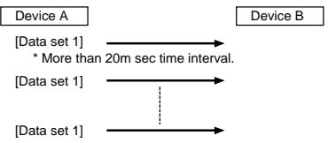
Device B requesting data from Device A
Device B sends an RQ1 message to Device A.
Checking the message, Device A sends a DT1 message back to Device B.
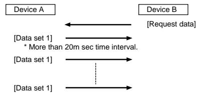
MIDI Implementation
Model: GR-33
Date: Jul. 21, 2000
Version: 1.01
1. Recognized Receive Data
■Channel Voice Message
Note Off
STATUS SECOND THIRD
8nH kkH vvH
9nH kkH 00H
n=MIDI Channel Number: 0H-FH(0-15) 0 = ch.1 15 = ch.16
kk=Note Number: 00H-7FH(0-127)
vv=Velocity: 00H-7FH(0-127)
Note On
STATUS SECOND THIRD
9nH kkH vvH
n=MIDI Channel Number: 0H-FH(0-15) 0=ch.1 15=ch.16
kk=Note Number: 00H-7FH(0-127)
vv=Velocity: 01H-7FH(1-127)
- vv=00H is received as Note-off (velocity 40H).
Control Change
Bank Select
STATUS SECOND THIRD
BnH 00H mmH
n=MIDI Channel Number: 0H-FH(0-15) 0=ch.1 15=ch.16
mm=Bank Number: 00H, 01H
- The LSB of Bank Select is ignored.
- Can be received only through the Basic channel.
OModulation
STATUS SECOND THIRD
BnH 01H vvH
n=MIDI Channel Number: 0H-FH(0-15) 0=ch.1 15=ch.16
vv=Modulation Depth: 00H-7FH(0-127)
- Can be received only through the Basic channel.
Foot Type
STATUS SECOND THIRD
BnH 04H vvH
n=MIDI Channel Number: 0H-FH(0-15) 0=ch.1 15=ch.16
vv=Control Value: 00H-7FH(0-127)
- Can be received only through the Basic channel.
Volume
STATUS SECONDTHIRD
BnH 07H vvH
n=MIDI Channel Number: 0H-FH(0-15) 0=ch.1 15=ch.16
vv=Volume: 00H-7FH(0-127)
- Can be received only through the Basic channel.
OPan
STATUS SECOND THIRD
BnH 0AH vvH
n=MIDI Channel Number: 0H-FH(0-15) 0=ch.1 15=ch.16
vv = Pan : 00H-40H-7FH(0-64-127)
- Can be received only through the Basic channel.
- The value 0 is left, 64 is center, and 127 is right. You can adjust in 127 steps from 0 to 127.
General Purpose #2
STATUS SECONDTHIRD
BnH 11H vvH
n=MIDI Channel Number: 0H-FH(0-15) 0=ch.1 15=ch.16
vv=Control Value: 00H-7FH(0-127)
0: minor, -7th,
1: minor, -6th,
2: minor, -5th,
3: minor, -4th,
4: minor, -3rd,
5: minor, -2nd,
6: minor, +2nd,
7: minor, +3rd,
8: minor, +4th,
9: minor, +5th,
10: minor, +6th,
11: minor, +7th
12: minor, Diminish,
64: major, -7th,
65: major, -6th,
66: major, -5th,
67: major, -4th,
68: major, -3rd,
69: major, -2nd,
70: major, +2nd,
71: major, +3rd,
72: major, +4th
73: major, +5th
74: major, +6th
75: major, +7th,
76: major, Diminish,
- Can be received only through the Basic channel.
- Received when Harmony is on, to switch the key between Major/Minor.
General Purpose #3
STATUS SECONDTHIRD
BnH 12H vvH
n=MIDI Channel Number: 0H-FH(0-15) 0=ch.1 15=ch.16
vv=Control Value: 00H-7FH(0-127)
- Can be received only through the Basic channel when this channel is set to POLY1-POLY16.
- When the Basic channel is set to MONO1-MONO11, reception takes place on the channels for each string.
- When the PLAY FEEL is set to ENVELOPE1 or ENVELOPE2, and recognized as the string envelope follow values.
General Purpose #4
STATUS SECONDTHIRD
BnH 13H vvH
n=MIDI Channel Number: 0H-FH(0-15) 0=ch.1 15=ch.16
vv=Control Value: 00H-7FH(0-127) 00H = Reset,
01H-3FH=OFF, 40H-7FH=ON
- Can be received only through the Basic channel.
- Having received this message, the GR-33 acts as if the onboard WAH(foot switch) is operated.
OHold1
| STATUS | SECOND | THIRD |
| BnH | 40H | vvH |
| n=MIDI Channel Number: | 0H-FH(0-15) 0=ch.1 15=ch.16 |
| vv=Control Value: | 00H-7FH(0-127) 00H-3FH=OFF,40H-7FH=ON |
- Can be received only through the Basic channel when this channel is set to POLY1-POLY16.
General Purpose #5
| STATUS | SECOND | THIRD |
| BnH | 50H | vwH |
n=MIDI Channel Number: 0H-FH(0-15) 0=ch.1 15=ch.16
vv=Control Value: 00H-7FH(0-127)00H-3FH=OFF,
40H-7FH=ON
- Functions as Tap Tempo Teach.
- Can be received only through the Basic channel when this channel is set to MONO1-MONO16.
General Purpose #6
| STATUS | SECOND | THIRD |
| BnH | 51H | vvH |
| n=MIDI Channel Number: | 0H-FH(0-15) 0=ch.1 15=ch.16 |
| vv=Control Value: | 00H-7FH(0-127) 00H-3FH=OFF, 40H-7FH=ON |
- Can be received only through the Basic channel when this channel is set to MONO1-MONO16.
- The specified function—MULTI-FX BYPASS, Arpeggiator, or Harmonist—will be switched on or off for each Patch.
General Purpose #7
| STATUS | SECOND | THIRD |
| BnH | 52H | vvH |
| n=MIDI Channel Number: | 0H-FH(0-15) 0=ch.1 15=ch.16 |
| vv=Control Value: | 00H-7FH(0-127) 00H-3FH=OFF,40H-7FH=ON |
- Can be received only through the Basic channel.
- Having received this message, the GR-33 acts as if the HOLD pedal is operated.
General Purpose #8
| STATUS | SECOND | THIRD |
| BnH | 53H | vwH |
| n=MIDI Channel Number: | 0H-FH(0-15) 0=ch.1 15=ch.16 |
| vv=Control Value: | 00H-7FH(0-127) 00H-3FH=OFF, |
| 40H-7FH=ON |
- Can be received only through the Basic channel.
- Having received this message, the GR-33 acts as if the CTRL pedal is operated when the Arpeggio is held.
General Effect 1 (Reverb Send Level)
| STATUS | SECOND | THIRD |
| BnH | 5BH | vwH |
| n=MIDI Channel Number: | 0H-FH(0-15) 0=ch.1 15=ch.16 |
| vv=Control Value: | 00H-7FH(0-127) |
- Can be received only through the Basic channel.
General Effect 3 (Chorus Send Level)
| STATUS | SECOND | THIRD |
| BnH | 5DH | vH |
| n=MIDI Channel Number: | 0H-FH(0-15) 0=ch.1 15=ch.16 |
| vv=Control Value: | 00H-7FH(0-127) |
- Can be received only through the Basic channel.
Program Change
| STATUS | SECOND |
| CnH | ppH |
| n=MIDI Channel Number: | 0H-FH(0-15) 0=ch.1 15=ch.16 |
| pp=Program Number: | 00H-7FH(0-127) 0=prg.1 127=prg.128 |
- Can be received only through the Basic channel.
- The recognized Program Change Number corresponds to each patch as follows.
| 1... | 4 = A11...A14 | 65...68 = C11...C14 |
| 5... | 8 = A21...A24 | 69...72 = C21...C24 |
| 9... | 12 = A31...A34 | 73...76 = C31...C34 |
| 13... | 16 = A41...A44 | 77...80 = C41...C44 |
| 17... | 20 = A51...A54 | 81...84 = C51...C54 |
| 21... | 24 = A61...A64 | 85...88 = C61...C64 |
| 25... | 28 = A71...A74 | 89...92 = C71...C74 |
| 29... | 32 = A81...A84 | 93...96 = C81...C84 |
| 33... | 36 = b11...b14 | 97...100 = d11...d2 |
| 37... | 40 = b21...b24 | 101...104 = d21...d2 |
| 41... | 44 = b31...b34 | 105...108 = d31...d3 |
| 45... | 48 = b41...b44 | 109...112 = d41...d4 |
| 49... | 52 = b51...b54 | 113...116 = d51...d5 |
| 53... | 56 = b61...b64 | 117...120 = d61...d6 |
| 57... | 60 = b71...b74 | 121...124 = d71...d7 |
| 61... | 64 = b81...b84 | 125...128 = d81...d8 |
- When you call the patches of the group E - H from the external device, send the value "1" of the control change number 0 before sending Program Change message.
| 1... 4 = E11...E14 | 65...68 = G11...G14 |
| 5... 8 = E21...E24 | 69...72 = G21...G24 |
| 9... 12 = E31...E34 | 73...76 = G31...G34 |
| 13... 16 = E41...E44 | 77...80 = G41...G44 |
| 17... 20 = E51...E54 | 81...84 = G51...G54 |
| 21... 24 = E61...E64 | 85...88 = G61...G64 |
| 25... 28 = E71...E74 | 89...92 = G71...G74 |
| 29... 32 = E81...E84 | 93...96 = G81...G84 |
| 33... 36 = F11...F14 | 97...100 = H11...H2 |
| 37... 40 = F21...F24 | 101...104 = H21...H2 |
| 41... 44 = F31...F34 | 105...108 = H31...H3 |
| 45... 48 = F41...F44 | 109...112 = H41...H4 |
| 49... 52 = F51...F54 | 113...116 = H51...H5 |
| 53... 56 = F61...F64 | 117...120 = H61...H6 |
| 57... 60 = F71...F74 | 121...124 = H71...H7 |
| 61... 64 = F81...F84 | 125...128 = H81...H8 |
- When you call the patches of the group A - d from the external device, send the value "0" of the control change number 0 before sending Program Change message.
Pitch Bend Change
| STATUS | SECOND | THIRD |
| EnH | IIH | mmH |
| n=MIDI Channel Number: | 0H-FH (0-15) | 0=ch.1 15=ch.16 |
| mm,ll=Value: | 00H, 00H - 7FH, 7FH (-8192 - +8191) | |
■Channel Mode Message
All Note Off
| STATUS | SECOND | THIRD |
| BnH | 7BH | 00H |
| n=MIDI Channel Number: | 0H-FH (0-15) | 0=ch.1 15=ch.16 |
- Can be received only through the Basic channel
- Turn off all notes that are now on.
- OMNI OFF
STATUS
BnH
SECOND
7CH
THIRD
00H
n = MIDI Channel Number:
0H-FH(0-15) 0=ch.1 15=ch.16
- Can be received only through the Basic channel.
- Will act the same as All Note Off.
- OMNI ON
STATUS
SECOND
THIRD
BnH
7DH
00H
n = MIDI Channel Number:
0H-FH(0-15) 0=ch.1 15=ch.16
- Can be received only through the Basic channel.
- Will act the same as All Note Off.
MONO
STATUS
SECOND
7EH
THIRD
mmH
n = MIDI Channel Number:
0H-FH(0-15) 0=ch.1 15=ch.16
mm=Number of Individual Channels:
00H-10H(0-16)
- Can be received only through the Basic channel.
- Will act the same as All Note Off.
POLY
STATUS
SECOND
7FH
THIRD
00H
n=MIDI Channel Number:
0H-FH(0-15) 0=ch.1 15=ch.16
- Can be received only through the Basic channel.
- Will act the same as All Note Off.
System Realtime Message
Active Sensing
STATUS
FEH
- Having received this message, the GR-33 expects to receive information of any status of data during about 420msec. If the GR-33 doesn't receive any message during that time, it acts as if the All Note Off message is received, and returns to normal operation (will not check interval of messages).
System Exclusive Message
STATUS
DATA BYTE
iiHddH
STATUS
eeH
F7H
FOH:
ii = ManufacturerID:
dd.....ee Data:
F7H:
System Exclusive
41H (65)
00H-7FH(0-127)
EOX (End Of Exclusive)
- For more details, refer to the page of "Roland Exclusive message" and Section 3 or after.
2. Transmitted Data
■Channel voice messages
Note Off
| STATUS | SECOND | THIRD |
| 9nH | kkH | 00H |
n=MIDI channel Number: 0H-FH(0-15) 0=ch.1 15=ch.16
kk=Note Number: 00H-7FH(0-127)
Note On
STATUS SECONDTHIRD
9nH kkH vvH
n=MIDI Channel Number: 0H-FH(0-15) 0=ch.1 15=ch.16
kk=Note Number: 00H-7FH(0-127)
vv = Velocity: 01H-7FH(1-127)
Control Change
Bank Select
STATUS SECOND THIRD
BnH 00H mmH
BnH 20H IIH
n=MIDI Channel Number: 0H-FH(0-15) 0=ch.1 15=ch.16
mm,ll=Bank Number: 00H, 00H - 7FH, 7FH (bank1-bank16384)
OModulation
STATUS SECOND THIRD
BnH 01H yyH
n=MIDI Channel Number: 0H-FH(0-15) 0=ch.1 15=ch.16
vv=Modulation Depth: 00H-7FH(0-127)
Foot type
STATUS SECONDTHIRD
BnH 04H vvH
n=MIDI Channel Number: 0H-FH(0-15) 0=ch.1 15=ch.16
vv=Control Value: 00H-7FH(0-127)
- When the Expression pedal is operated, the GR-33 sends this as the operation(Except some noted setting of the "EXP PEDAL" paramater).
Data Entry
STATUS SECOND THIRD
BnH 06H mmH
BnH 26H IIH
n=MIDI Channel Number: 0H-FH(0-15) 0=ch.1 15=ch.16
mm,ll=the value of the parameter specified by RPN
Volume
STATUS SECONDTHIRD
BnH 07H vvH
n=MIDI Channel Number: 0H-FH(0-15) 0=ch.1 15=ch.16
vv=Volume: 00H-7FH(0-127)
- Transmitted the total volume fixed with expression pedal and GK-2A operation.
- Not transmitted when the VOLUME SEND SW of SYSTEM menu is OFF.
OPan
STATUS SECOND THIRD
BnH 0AH vvH
n=MIDI Channel Number: 0H-FH(0-15) 0=ch.1 15=ch.16
vv=Pan: 00H-40H-7FH(0-64-127)
- Transmitted the action of the expression pedal when "EXP pedal" is set to "Pan (Normal)".
General Purpose #2
| STATUS | SECOND | THIRD |
| BnH | 11H | vwH |
n=MIDI Channel Number: 0H-FH(0-15) 0=ch.1 15=ch.16
vv=Control Value: 00H-7FH(0-127)00H-3FH=Major,
40H-7FH=Minor
- Transmitted when an external pedal is used to switch the harmony key between Major/ Minor.
General Purpose #3
| STATUS | SECOND | THIRD |
| BnH | 12H | vwH |
n=MIDI Channle Number: 0H-FH(0-15) 0=ch.1 15=ch.16
vv=Control Value: 00H-7FH(0-127)
- Transmitted the envelope data of the strings when the "PLAY FEEL" is set to ENVELOPE1 or ENVELOPE2.
- Data is sent only in Mono mode. Transmission doesn't take place in Poly mode.
General Purpose #4
| STATUS | SECOND | THIRD |
| BnH | 13H | vvH |
n=MIDI Channel Number: 0H-FH(0-15) 0=ch.1 15=ch.16
vv=Control value: 00H-7FH(0-127) 00H = Reset,
01H-3FH=OFF, 40H-7FH=ON
- Transmitted the operation of onboard WAH function (Pedal 1).
General Purpose #6
| STATUS | SECOND | THIRD |
| BnH | 51H | vwH |
n=MIDI Channel Number: 0H-FH(0-15) 0=ch.1 15=ch.16
vv=Control value: 00H-7FH(0-127)00H-3FH=OFF,
40H-7FH=ON
- Transmitted the operation of turning ON or OFF by CTRL pedal when this channel is set to MONO1-MONO16.
General Purpose #7
| STATUS | SECOND | THIRD |
| BnH | 52H | vvH |
n=MIDI Channel Number: 0H-FH(0-15) 0=ch.1 15=ch.16
vv=Control Value: 00H-7FH(0-127)00H-3FH=OFF,
40H-7FH=ON
- Transmitted the operation of onboard HOLD pedal when this channel is set to MONO1-MONO16.
General Purpose #8
| STATUS | SECOND | THIRD |
| BnH | 53H | vwH |
n=MIDI Channel Number: 0H-FH(0-15) 0=ch.1 15=ch.16
vv=Control Value: 00H-7FH(0-127)00H-3FH=OFF,
40H-7FH=ON
- Transmitted the operation of CTRL pedal when the Arpeggio is held, and the HOLD TYPE is set to Latch Type A/B.
General Effect #1 (Reverb Send Level)
| STATUS | SECOND | THIRD |
| BnH | 5BH | vvH |
n=MIDI Channel Number: 0H-FH(0-15) 0 = ch.1 15 = ch.16
vv=Control Value: 00H-7FH(0-127)
- Transmitted the action of the EXP pedal when the EXP pedal is set to "REV SEND LEVEL".
General Effect #3 (Chorus Send Level)
| STATUS | SECOND | THIRD |
| BnH | 5DH | vvH |
n=MIDI Channel Number: 0H-FH(0-15) 0=ch.1 15=ch.16
vv=Control Value: 00H-7FH(0-127)
- Transmitted the action of the EXP pedal when the EXP pedal is set to "CHO SEND LEVEL".
ORPN MSB/LSB
| STATUS | SECOND | THIRD |
| BnH | 65H | mmH |
| BnH | 64H | llH |
n=MIDI Channel Number: 0H-FH(0-15) 0=ch.1 15=ch.16
mm=Upper byte of the parameter data designated by RPN
ll=Lower byte of the parameter data designated by RPN
<
Control change includes RPN(registered parameter number), function which are defined by the MIDI standard.
The GR-33 can transmit only one RPN: pitch bend sensitivity(RPN#0).
RPN Data entry
MSB LSB MSB LSB Function
00H 00H mmH 00H pitch bend sensitivity The transmitted lower byte is always 00H.
- Transmitted when you change the BEND RANGE parameter on SYSTEM menu.
- Not transmitted when BEND REQ SW on SYSTEM menu is set to OFF.
Program change
| STATUS | SECOND |
| CnH | ppH |
n=MIDI Channel Number: 0H-FH(0-15) 0=ch.1 15=ch.16
pp=Program Number: 00H-7FH(0-127) 0 = prg.1127 = prg.128
Pitch Bend Change
| STATUS | SECOND | THIRD |
EnH lIH mmH
n=MIDI Channel Number: 0H-FH(0-15) 0=ch.1 15=ch.16
mm,ll=Value: 00H, 00H - 7FH, 7FH (-8192 - +8191)
System Realtime Message
Active Sensing
STATUS
FEH
- This message is always transmitted at about 270msec' interval.
System Exclusive message
| STATUS | DATA BYTES | STATUS |
| F0H | iiH,ddH,...,eeH | F7H |
F0H: System Exclusive
ii=ID Number: 41H (65)
dd,...,ee=Data: 00H-7FH (0-127)
F7H: EOX (End of Exclusive/System Common Message)
- For more details, refer to the page "Roland exclusive message" and Section3 or after.
3. Exclusive Communications
The GR-33 can transmit or receive system and patches parameters using system exclusive messages. Model ID of exclusive message available on the GR-33 is 00H 30H. Device ID is fixed at 10H.
When the GR-33 receives an Identify Request inquiry message, it will transmit an Identity Reply.
Request Data1 RQ1 (11H)
This message is to request the GR-33 to transmit its parameters.
The address and size indicate the type and amount of parameters requested.
The GR-33 itself does not send this message.
When the GR-33 receives this message, it responds with appropriate parameters if the following conditions are satisfied:
- The address indicated with RQ1 matches with one of the parameter base address of the GR-33.
- The requested size is larger than 2.
- When the Bulk Load standby in System mode.
With these conditions provided, the GR-33 transmits specified parameters in Data Set 1 (DT1) message.
Bytes Comments
F0H System Exclusive Status
41H Manufacturer ID (Roland)
10H Device ID (Dev=10H)
00H Model ID MSB (GR-33)
30H Model ID LSB (GR-33)
11H Command ID (RQ1)
aaH Address MSB
bbH Address
ccH Address
ddH Address LSB
ssH Size MSB
ssH Size
ssH Size
ssH Size LSB
sum Check sum
F7H EOX (End Of Exclusive)
- Data Set 1: DT1 (12H)
The GR-33 transmits this message in the following conditions.
If the address matches with one of the parameter base addresses of the GR-33, the received data is stored at the specified address of the memory.
- The message that can be received is only the one with data size of larger than two bytes.
The GR-33 transmits this message in the following conditions.
When data request (RQ1) is received with the Bulk Load standby in System mode, and the specified parameters are transmitted.
or you executes Bulk Dump function.
Regarding details of the parameter transmitted/sended, please refer to the Parameter Address Map.
Bytes Comments
F0H System Exclusive Status
41H Manufacturer ID (Roland)
10H Device ID (Dev = 10H)
00H Model ID MSB (GR-33)
30H Model ID LSB (GR-33)
12H Command ID (DT1)
aaH Address MSB
bbH Address
ccH Address
ddH Address LSB
eeH Data
:
ffH Data
sum Check Sum
F7H EOX (End of Exclusive)
Model ID
The Model ID of the GR-33 is 00H 30H.
Device ID
Device ID of the GR-33 is fixed at 10H.
/Example of creating the exclusive message/
If you want to set as the following the reverb parameter of temporary patch, create data as the following and send it to your GR-33.
Reverb setting:
REVERB TYPE : Hall1
REVSENDLEVEL:115
REVERB TIME:90
REVERB HF DAMP: Bypass
Transmitted data:
FOH 41H 10H 00H 30H 12H 02H 00H 00H 60H 04H 73H 5AH 11H 3CH F7H 1 2 3 4 5 6 7 8 9
- Exclusive status is F0H.
- Roland's Manufacturer ID is 41H.
- This is the device ID.(Fixed at 10H for GR-33)
- Model ID of the GR-33 is 00H 30H.
- DT1(Data Set1) Command ID is 12H.
- These are the parameter addresses. Please find the start address of the temporary Patch from the table of the start address. You can find the address as 02H 00H 00H 00H.
Next, please find the offset address of the Reverb Type from the table 4-2. That is 00H 00H 60H. The result will be 02H 00H 00H 60H.
02H 00H 00H 00H (the start address of the temporary patch) +) 00H 00H 61H (the offset address of the Reverb Type)
02H 00H 00H 61H
- The settings value for REVERB TYPE Hall1 is 4. This is expressed as 04H in hexadecimal notation with two digits. (Refer to the attached Chart A-1)
The settings value for REV SEND LEVEL is 115. This is expressed as 73H in hexadecimal notation with two digits.
The settings value for REVERB TIME is 90. This is expressed as 5AH in hexadecimal notation with two digits.
The settings value for REVERB HF DAMP Bypass is 0. This is expressed as 00H in hexadecimal notation with two digits. - This is the check sum byte.The error checking process uses a Checksum and provides a pattern where the last significant 7 bits are zero when values for address, data(or size) and the Checksum are summed.
If the address of the exclusive message that you wish to send is aa bb cc ddH and the data(or size) is ee ff hh iiH,
aa + bb + cc + dd + ee + ff + hh + ii = sum
sum ÷ 128 = quotient...remainder
128 - remainder = checksum
- However, when sum=0, then the checksum also results in 0.
In case of this example,
F0H 41H 10H 00H 30H 12H 02H 00H 00H 60H 04H 73H 5AH 11H ??H F7H address data checksum
Using the above formula, Checksum will be as follows.
02H + 00H + 00H + 60H + 04H + 73H + 5AH + 11H = 2 + 0 + 0 + 96 + 4 + 115 + 90 + 17 = 324(sum) 324(sum)÷ 128 = 2(quotient) 68(remainder)
[ \text{checksum} = 128 - 68(\text{remainder}) = 60 = 3\text{CH} ]
If you calculate with hexadecimal,
aa + bb + cc + dd + ee + ff = sum(xxH)
sum(xxH)÷ 80H = quotient...remainder
80H - remainder = checksum
Checksum will be as follows.
02H + 00H + 00H + 60H + 04H + 73H + 5AH + 11H = 144H
144H÷ 80H = 02H(quotient) 44H(remainder)
[ \text{checksum} = 80\mathrm{H} - 44\mathrm{H}(\text{remainder}) = 3\mathrm{CH} ]
- F7H is the mark of the end of exclusive.
Inquiry Message
Oldentity Request
| Bytes | Comments |
| F0H | Exclusive Status |
| 7EH | ID number (Universal Non-realtime Message) |
| 10H | Device ID |
| 06H | SubID#1 |
| 01H | SubID#2 |
| F7H | EOX (End of Exclusive) |
- The 7FH (Broadcast) device ID is also supported.
- Identity request can be received when Bulk Load is standby in System mode.
- When an Identity Request is received, the GR-33 will transmit the following Identity Reply.
Identity Reply
| Bytes | Comments |
| F0H | Exclusive Status |
| 7EH | ID number (Universal Non-realtime Message) |
| 10H | Device ID (fixed at 10H) |
| 06H | SubID#1 |
| 02H | SubID#2 |
| 41H | ID number(Roland) |
| 30H 01H | Device Family Code |
| 00H 00H | Device Family Number Code |
| 00H 00H 00H 00H | Software Revision Level |
| F7H | EOX (End of Exclusive) |
- When an Identity Request is received, the GR-33 will transmit the above Identity Reply.
4. Parameter Address Map
Addresses and sizes are expressed in 7-bit hexadecimal values.
| Address | MSB | LSB | |
| Binary | 0aaa aaaa | 0bbb bbbb | 0ccc ccccc0ddd dddd |
| 7 bit Hex | AA | BB | CCDD |
| Size | MSB | LSB | |
| Binary | 0sss ssss | 0ttt tttt | 0uuu uuuu0vvv vvvv |
| 7 bit Hex | SS | TT | UUVV |
| Start Address | Contents and Remarks |
| 00 00 00 00 | System Area *4-1 |
| 01 00 00 00 | Patch A11 (1) *4-2 |
| 01 01 00 00 | Patch A12 (2) *4-2 |
| 01 02 00 00 | Patch A13 (3) *4-2 |
| 01 03 00 00 | Patch A14 (4) *4-2 |
| 01 7F 00 00 | Patch D84 (128) *4-2 |
| 02 00 00 00 | Temporary Patch *4-2 |
- 4-1 System Area(Total size = 24H)
| Offset Address | Data | Contents | Remarks |
| 00 00 00 | 00 - 01 | OUTPUT SELECT | Line, Guitar Amp |
| 00 00 01 | 00 - 03 | GUITAR SELECT | Gtrl - 4 |
| 00 00 02 | 00 - 7E | MASTER TUNE | 427.4 - 452.6 [Hz] |
| 00 00 03 | 00 - 01 | G.AMP SIM | Off, On |
| 00 00 04 | 00 - 07 | BEND RANGE | 0, 1, 2, 4, 5, 7, 12, 24 [semi tone] |
| 00 00 05 | 00 - 01 | BEND DATA THIN | Off, On |
| 00 00 06 | 00 - 1A | BASIC CHANNEL | Mono 1 - 11, Poly 1 - 16 |
| 00 00 07 | 00 - 01 | S1/S2 FUNCTION | Normal, Patch Select |
| 00 00 08 | 00 - 01 | DIAL FUNCTION | PATCH & VALUE, VALUE Only |
| 00 00 09 | 00 - 01 | DISPLAY TYPE | Grp/Bnk/Num, Decimal |
| 00 00 0A | 00 - 01 | BEND REQ SW | Off, On |
| 00 00 0B | 00 - 01 | VOL SEND SW | Off, On |
| 00 00 0C | 00 - 07 | PICKUP SENS 1 | (String #1) (String #2) (String #3) (String #4) (String #5) (String #6) |
| 00 00 0D | |||
| 00 00 0E | |||
| 00 00 0F | |||
| 00 00 10 | |||
| 00 00 11 | |||
| 00 00 12 | 00 - 07 | PICKUP SENS 2 | (String #1) (String #2) (String #3) (String #4) (String #5) (String #6) |
| 00 00 13 | |||
| 00 00 14 | |||
| 00 00 15 | |||
| 00 00 16 | |||
| 00 00 17 | |||
| 00 00 18 | 00 - 07 | PICKUP SENS 3 | (String #1) (String #2) (String #3) (String #4) (String #5) (String #6) |
| 00 00 19 | |||
| 00 00 1A | |||
| 00 00 1B | |||
| 00 00 1C | |||
| 00 00 1D |
| 00 00 1E 00 00 1F 00 00 20 00 00 21 00 00 22 00 00 23 | 00 - 07 | PICKUP SENS 4 | (String #1) (String #2) (String #3) (String #4) (String #5) (String #6) | 1 - 8 |
/Example using RQ1/
To extract the all system parameters, send the following message to the GR-33.
F0 41 10 00 30 11 00 00 00 00 00 00 00 24 5C F7
/Example using DT1/
To change BEND RANGE to 12 and BEND DATA THIN to Off, send the following message to the GR-33.
F0 41 10 00 30 12 00 00 00 04 06 00 76 F7
- 4-2 Patch(Total size = 01H 00H)
| Offset Address | Data | Contents | Remarks |
| 00 00 00 :00 00 0B | 20 - 7F | PATCH NAME 1 - 12 | ASCII Character |
| 00 00 0C | 00 - 64 | PATCH LEVEL | 0 - 100 |
| 00 00 0D | 00 - 0F | PLAY FEEL | Normal, Finger, Hard, Soft, Tapping, No Dynamics, Envelopel, Envelope2, Accl Normal, Accl Finger, Accl Hard, Accl Soft, Accl Tapping, Accl No Dynamics, Accl Envelopel, Accl Envelope2 |
| 00 00 0E | 00 - 0B | PAN MODE | Normal, Cross Tones, 1-6, 6-1, Odd-Even, Even-Odd, Random Both, Random 1st, Random 2nd, Alternate Both, Alternate 1st, Alternate 2nd |
| 00 00 0F | 0E - 72 | PAN | -50 - +50 *1) |
| 00 00 10 | 00 - 03 | CHROMATIC | Off, Type1, Type2, Type3 |
| 00 00 11 | 00 - 23 | WAH TYPE | Wahl - 5, AutoWahl - 5, Brightness1 - 5, NarrowWahl - 5, R.Wahl - 5, R.Brightness1 - 5, R.NarrowWahl - 5, Modulation |
| 00 00 12 | 00 - 0D | GLIDE TYPE | Down7 - 1, Upl - 7 |
| 00 00 13 | 00 - 0E | HOLD TYPE (for Arpeggio OFF) | Damper All, Damper 1st, Damper 2nd, Damper 1&2, Damper Ext, Damper Ext&1, Damper Ext&2, Sostenuto All, Sostenuto 1st, Sostenuto 2nd, Sostenuto 1&2, Sostenuto Ext, Sostenuto Ext&1, Sostenuto Ext&2, String |
| 00 00 14 | 00 - 03 | HOLD TYPE (for Arpeggio ON) | Damper, Sostenuto, Latch TypeA, Latch TypeB |
| 00 00 15 | 00 - 01 | CTRL PEDAL | HAR/ARP Control, Multi-FX Bypass |
| 00 00 16 | 00 - 50 | EXP PEDAL | Volume, Volume 1st, Volume 2nd, Balance, Tone Param, Multi-FX Param, Brightness, Wah, Pitch, Modulation, Pan(Normal), Pan(Cross Tones), Cho Send Level, Rev Send Level, Arp Tempol - 3, Tempo & Pitch, CC 1 - 31, CC 64 - 95 |
| 00 00 1700 00 1800 00 1900 00 1A00 00 1B00 00 1C | 00 - 7F | MIDI [PC] (String #1)(String #2)(String #3)(String #4)(String #5)(String #6) | Transmit Program Change #1 - 128 |
| 00 00 1D00 00 1E00 00 1F00 00 2000 00 2100 00 22 | 00 - 01 | MIDI [PC] (Off/On) (String #1)(String #2)(String #3)(String #4)(String #5)(String #6) | 0: Transmit Program Change = Off, 1: Transmit Program Change = On |
| 00 00 2300 00 2400 00 2500 00 2600 00 2700 00 28 | 00 - 7F | MIDI [CC0] (String #1)(String #2)(String #3)(String #4)(String #5)(String #6) | Transmit CC#0 0 - 127 |
| 00 00 2900 00 2A00 00 2B00 00 2C00 00 2D00 00 2E | 00 - 01 | MIDI [CC0] (Off/On) (String #1)(String #2)(String #3)(String #4)(String #5)(String #6) | 0: Transmit CC#0 = Off, 1: Transmit CC#0 = On |
| 00 00 2F00 00 3000 00 3100 00 3200 00 3300 00 34 | 00 - 7F | MIDI [CC32] (String #1)(String #2)(String #3)(String #4)(String #5)(String #6) | Transmit CC#32 0 - 127 |
| 00 00 3500 00 3600 00 3700 00 3800 00 3900 00 3A | 00 - 01 | MIDI [CC32] (Off/On) (String #1)(String #2)(String #3)(String #4)(String #5)(String #6) | 0: Transmit CC#32 = Off, 1: Transmit CC#32 = On |
| 00 00 3B00 00 3C00 00 3D00 00 3E00 00 3F00 00 40 | 1C - 58 | MIDI [TRANSPOSE] (String #1)(String #2)(String #3)(String #4)(String #5)(String #6) | -36 - 24 [semi tone] |
| 00 00 41 | always 00 | (reserved) | (reserved) |
| 00 00 4200 00 43 | 0000 - 017F | 1ST SELECT (LSB)(MSB) | 0 - 383 (as Tone Number 001 - 384) *2) |
| 00 00 44 | OE - 72 | 1ST ATTACK | -50 - +50 |
| 00 00 45 | OE - 72 | 1ST RELEASE | -50 - +50 |
| 00 00 46 | OE - 72 | 1ST BRIGHTNESS | -50 - +50 |
| 00 00 4700 00 4800 00 4900 00 4A00 00 4B00 00 4C | 1C - 58 | 1ST TRANSPOSE (String #1)(String #2)(String #3)(String #4)(String #5)(String #6) | -36 - +24 [semi tone] |
| 00 00 4D | always 00 | (reserved) | (reserved) |
| 00 00 4E00 00 4F | 0000 - 017F | 2ND SELECT (LSB)(MSB) | 0 - 383 (as Tone Number 001 - 384) *2) |
| 00 00 50 | OE - 72 | 2ND ATTACK | -50 - +50 |
| 00 00 51 | OE - 72 | 2ND RELEASE | -50 - +50 |
| 00 00 52 | OE - 72 | 2ND BRIGHTNESS | -50 - +50 |
| 00 00 5300 00 5400 00 5500 00 5600 00 5700 00 58 | 1C - 58 | 2ND TRANPOSE (String #1)(String #2)(String #3)(String #4)(String #5)(String #6) | -36 - +24 [semi tone] |
| 00 00 59 | OE - 72 | 1:2 BALANCE | -50 - +50 |
| 00 00 5A00 00 5B00 00 5C00 00 5D00 00 5E00 00 5F | 00 - 05 | LAYER (String #1)(String #2)(String #3)(String #4)(String #5)(String #6) | Mute, 1st Tone, 2nd Tone, Both Tone, Weak Detune, Strong Detune |
| 00 00 60 | 00 - 07 | REVERB TYPE | Room1 - 2, Stagel - 2, Hall1 - 2, Delay, Pan Delay |
| 00 00 61 | 00 - 7F | REV SEND LEVEL | 0 - 127 |
| 00 00 62 | 00 - 7F | REVERB TIME | 0 - 127 |
| 00 00 63 | 00 - 11 | REVERB HF DAMP | 200, 250, 315, 400, 500, 630, 800, 1000, 1250, 1600, 2000, 2500, 3150, 4000, 5000, 6300, 8000 [Hz], Bypass |
| 00 00 64 | 00 - 7F | DELAY FEEDBACK | 0 - 127 |
| 00 00 65 | 00 - 7F | CHO SEND LEVEL | 0 - 127 |
| 00 00 66 | 00 - 7F | CHORUS RATE | 0 - 127 |
| 00 00 67 | 00 - 7F | CHORUS DEPTH | 0 - 127 |
| 00 00 68 | 00 - 7F | CHORUS PRE-DELAY | 0 - 127 |
| 00 00 69 | 00 - 7F | CHORUS FEEDBACK | 0 - 127 |
| 00 00 6A | 00 - 03 | MULTI-FX SW | Off, 1st, 2nd, Both |
| 00 00 6B | 00 - 27 | MULTI-FX TYPE | STEREO-EQ, OVERDRIVE, DISTORTION, PHASER, SPECTRUM, ENHANCED, AUTO-WAH, ROTARY, COMPRESSOR, LIMITER, HEXA-CHORUS, TREMOLO-CHO, SPACE-D, STERE-O-CHO, STERE-FL, STEP-FL, STERE-DELAY, MOD-DELAY, 3-TAP-DELAY, 4-TAP-DELAY, TIMETCR-LDY, 2VOICE-P.SFT, FB-P.SFT, REVERB, GATE-REVERB, OD->CHO, OD->FL, OD->DLY, DS->CHO, DS->FL, DS->DLY, EH->CHO, EH->FL, EH->DLY, CHO->DLY, FL->DLY, CHO->FL, CHO/DLY, FL/DLY, CHO/FL |
| 00 00 6C :00 00 77 | 00 - 7F | MULTI-FX PARAMETER 1 - 12 | 0 - 127 *3) |
| 00 00 78 | 00 - 01 | HAR/ARP CONTROL | Off, On |
| 00 00 79 | 00 - 0D | HAR/ARP SELECT | Harmony All, Harmony 1st, Harmony 2nd, Harmony l&2, Harmony Ext, Harmony Ext&l, Harmony Ext&2, Arpeggio All, Arpeggio 1st, Arpeggio 2nd, Arpeggio 1&2, Arpeggio Ext, Arpeggio Ext&l, Arpeggio Ext&2 |
| 00 00 7A | 00 - 0C | HARMONY STYLE | -7th, -6th, -5th, -4th, -3rd, -2nd, +2nd, +3rd, +4th, +5th, +6th, +7th, Diminish |
| 00 00 7B | 00 - 17 | HARMONY KEY | C,C#, D,D#, E,F#, G#, G#, A,A#, B,Cm, C#m, Dm, D#m, Em, Fm, F#m, Gm, G#m, Am, A#m, Bm |
| 00 00 7C | 00 - 01 | HARMONY REMOTE | Off, On |
| 00 00 7D00 00 7E | 0032 - 00FA | ARP TEMPO (LSB)(MSB) | 50 - 250 [b.p.m] *2) |
| 00 00 7F | 00 - 31 | ARP PATTERN | Pattern No. 1 - 50 *4) |
- 1) This parameter is enabled only when PAN MODE is set to Normal or Cross Tones.
- 2) This parameter is expressed with the parameter value equal to (MSB * 80H) + LSB. It is disregarded when only the MSB or LSB is received.
- 3) The correspondence of MULTI-FX PARAMETER 1-12 for each MULTI-FX TYPE is shown below (p. 113-117). Parameters appended with "#" can be controlled with the EXP pedal when the EXP PEDAL parameter is set to Multi-FX Param.
| MULTI-FX TYPE | MULTI-FX PARAMETER | Data | Remarks |
| 1. STEREO-EQ | 1. LOW FREQ | 00 - 01 | 200, 400 [Hz] |
| 2. LOW GAIN | 00 - 1E | -15 - +15 [dB] | |
| 3. HIGH FREQ | 00 - 01 | 4000, 8000 [Hz] | |
| 4. HIGH GAIN | 00 - 1E | -15 - +15 [dB] | |
| 5. P1 FREQ | 00 - 10 | 200, 250, 315, 400, 500, 630, 800, 1000, 1250, 1600, 2000, 2500, 3150, 4000, 5000, 6300, 8000 [Hz] | |
| 6. P1 Q | 00 - 04 | 0.5, 1.0, 2.0, 4.0, 9.0 | |
| 7. P1 GAIN | 00 - 1E | -15 - +15 [dB] | |
| 8. P2 FREQ | 00 - 10 | 200, 250, 315, 400, 500, 630, 800, 1000, 1250, 1600, 2000, 2500, 3150, 4000, 5000, 6300, 1000, 1250, 1600, 2000, 2500, 3150, 4000, 5000, 6300, 8000 [Hz] | |
| 9. P2 Q | 00 - 04 | 0.5, 1.0, 2.0, 4.0, 9.0 | |
| 10. P2 GAIN | 00 - 1E | -15 - +15 [dB] | |
| #11. LEVEL | 00 - 7F | 0 - 127 | |
| 12. - | |||
| 2. OVERDRIVE | #1. DRIVE | 00 - 7F | 0 - 127 |
| 2. PAN | 00 - 7F | L64 - R63 | |
| 3. AMP TYPE | 00 - 03 | Small, Built-In, 2-Stack, 3-Stack | |
| 4. LOW GAIN | 00 - 1E | -15 - +15 [dB] | |
| 5. HIGH GAIN | 00 - 1E | -15 - +15 [dB] | |
| 6. LEVEL | 00 - 7F | 0 - 127 | |
| 7. - | |||
| 8. - | |||
| 9. - | |||
| 10. - | |||
| 11. - | |||
| 12. - | |||
| 3. DISTORTION | #1. DRIVE | 00 - 7F | 0 - 127 |
| 2. PAN | 00 - 7F | L64 - R63 | |
| 3. AMP TYPE | 00 - 03 | Small, Built-In, 2-Stack, 3-Stack | |
| 4. LOW GAIN | 00 - 1E | -15 - +15 [dB] | |
| 5. HIGH GAIN | 00 - 1E | -15 - +15 [dB] | |
| 6. LEVEL | |||
| 00 - 7F | |||
| 0 - 127 | |||
| 7. - | |||
| 8. - | |||
| 9. - | |||
| 10. - | |||
| 11. - | |||
| #11. LEVEL | |||
| 00 - 7F | |||
| 0 - 127 | |||
| 12. - | |||
| 4. PHASER | 1. MANUAL | 00 - 7D | 100 - 8000 [Hz] |
| #2. RATE | 00 - 7D | 0.05 - 10.0 [Hz] | |
| 3. DEPTH | 00 - 7F | 0 - 127 | |
| 4. RESONANCE | 00 - 7F | 0 - 127 | |
| 5. MIX | 00 - 7F | 0 - 127 | |
| 6. PAN | |||
| 00 - 7F | |||
| L64 - R63 | |||
| 7. LEVEL | |||
| 00 - 7F | |||
| 0 - 127 | |||
| 8. - | |||
| 9. - | |||
| 10. - | |||
| 11. - | |||
| 12. - | |||
| 5. SPECTRUM | |||
| 1. BAND1 | 00 - 1E | -15 - +15 [dB] | |
| 2. BAND2 | 00 - 1E | -15 - +15 [dB] | |
| 3. BAND3 | 00 - 1E | -15 - +15 [dB] | |
| 4. BAND4 | 00 - 1E | -15 - +15 [dB] | |
| 5. BAND5 | 00 - 1E | -15 - +15 [dB] | |
| 6. BAND6 | 00 - 1E | -15 - +15 [dB] | |
| 7. BAND7 | 00 - 1E | -15 - +15 [dB] | |
| 8. BAND8 | 00 - 1E | -15 - +15 [dB] | |
| 9. Q | 00 - 04 | 0.5, 1.0, 2.0, 4.0, 8.0 | |
| 10. PAN | 00 - 7F | L64 - R63 | |
| #11. LEVEL | 00 - 7F | 0 - 127 | |
| 12. - | |||
| 6. ENHANCED | 1. SENS | 00 - 7F | 0 - 127 |
| #2. MIX | 00 - 7F | 0 - 127 | |
| 3. LOW GAIN | 00 - 1E | -15 - +15 [dB] | |
| 4. HIGH GAIN | 00 - 1E | -15 - +15 [dB] | |
| 5. LEVEL | 00 - 7F | 0 - 127 | |
| 6. - | |||
| # 7. LEVEL | 00 - 7F | 0 - 127 | |
| 8. - | - | - | |
| 9. - | - | - | |
| 10. - | - | - | |
| 11. - | - | - | |
| 12. - | - | - | |
| 10. LIMITER | 1. THRESHOLD | 00 - 7F | 0 - 127 |
| 2. RELEASE | 00 - 7F | 0 - 127 | |
| 3. RATIO | 00 - 03 | 1.5:1, 2:1, 4:1, 100:1 | |
| 4. PAN | 00 - 7F | L64 - R63 | |
| 5. POST GAIN | 00 - 03 | 0, +6, +12, +18 [dB] | |
| 6. LOW GAIN | 00 - 1E | -15 - +15 [dB] | |
| 7. HIGH GAIN | 00 - 1E | -15 - +15 [dB] | |
| # 8. LEVEL | 00 - 7F | 0 - 127 | |
| 9. - | - | - | |
| 10. - | - | - | |
| 11. - | - | - | |
| 12. - | - | - | |
| 11. HEXA-CHORUS | 1. PRE DELAY | 00 - 7D | 0.0 - 100 [msec] |
| # 2. RATE | 00 - 7D | 0.05 - 10.0 [Hz] | |
| 3. DEPTH | 00 - 7F | 0 - 127 | |
| 4. PRE DLY DEV | 00 - 14 | 0 - 20 | |
| 5. DEPTH DEV | 00 - 28 | -20 - 20 | |
| 6. PAN DEV | 00 - 14 | 0 - 20 | |
| 7. BALANCE | 00 - 64 | D100:OE - D0:100E | |
| 8. LEVEL | 00 - 7F | 0 - 127 | |
| 9. - | - | - | |
| 10. - | - | - | |
| 11. - | - | - | |
| 12. - | - | - | |
| 12. TREMOLO-CHO | 1. PRE DELAY | 00 - 7D | 0.0 - 100 [msec] |
| 2. CHORUS RATE | 00 - 7D | 0.05 - 10.0 [Hz] | |
| 3. CHORUS DEPTH | 00 - 7F | 0 - 127 | |
| # 4. TREM RATE | 00 - 7D | 0.05 - 10.0 [Hz] | |
| 5. TREM SEP | 00 - 7F | 0 - 127 | |
| 6. TREM PHASE | 00 - 5A | 0 - 180 | |
| 7. BALANCE | 00 - 64 | D100:OE - D0:100E | |
| 8. LEVEL | 00 - 7F | 0 - 127 | |
| 9. - | - | - | |
| 10. - | - | - | |
| 11. - | - | - | |
| 12. - | - | - - | |
| 13. SPACE-D | 1. PRE DELAY | 00 - 7D | 0.0 - 100 [msec] |
| # 2. RATE | 00 - 7D | 0.05 - 10.0 [Hz] | |
| 3. DEPTH | 00 - 7F | 0 - 127 | |
| 4. PHASE | 00 - 5A | 0 - 180 | |
| 5. LOW GAIN | 00 - 1E | -15 - +15 [dB] | |
| 6. HIGH GAIN | 00 - 1E | -15 - +15 [dB] | |
| 7. BALANCE | 00 - 64 | D100:OE - D0:100E | |
| 8. LEVEL | 00 - 7F | 0 - 127 | |
| 9. - | - | - | |
| 10. - | - | - | |
| 11. - | - | - | |
| 12. - | - | - | |
| 14. STEREO-CHO | 1. FILTER TYPE | 00 - 02 | |
| OFF, LPF, HPF | |||
| 2. CUTOFF FREQ | 00 - 10 | 200, 250, 315, 400, 500, 630, 800, 1000, 1250, 1600, 2000, 2500, 3150, 4000, 5000, 6300, 8000 [Hz] | |
| 3. PRE DELAY | 00 - 7D | 0.0 - 100 [msec] | |
| # 4. RATE | 00 - 7D | 0.05 - 10.0 [Hz] | |
| 5. DEPTH | 00 - 7F | 0 - 127 | |
| 6. PHASE | 00 - 5A | 0 - 180 | |
| 7. - | - | - | |
| 8. LOW GAIN | 00 - 1E | -15 - +15 [dB] | |
| 9. HIGH GAIN | 00 - 1E | -15 - +15 [dB] | |
| 10. BALANCE | 00 - 64 | D100:OE - D0:100E | |
| 11. LEVEL | 00 - 7F | 0 - 127 | |
| 12. - | - | - | |
| 15. STEREO-FL | 1. FILTER TYPE | 00 - 02 | |
| OFF, LPF, HPF | |||
| 2. CUTOFF FREQ | 00 - 10 | 200, 250, 315, 400, 500, 630, 800, 1000, 1250, 1600, 2000, 2000, 3150, 4000, 5000, 6300, 8000 [Hz] | |
| 3. PRE DELAY | 00 - 7D | 0.0 - 100 [msec] | |
| # 4. RATE | 00 - 7D | 0.05 - 10.0 [Hz] | |
| 5, DEPTH | 00 - 7F | 0 - 127 | |
| 6. PHASE | 00 - 5A | 0 - 180 | |
| 7. FEEDBACK | 00 - 62 | -98 - 98 [%] | |
| 8. LOW GAIN | 00 - 1E | -15 - +15 [dB] | |
| 9. HIGH GAIN | 00 - 1E | -15 - +15 [dB] | |
| 10. BALANCE | 00 - 64 | D100:OE - D0:100E | |
| 11. LEVEL | 00 - 7E | 0 - 127 | |
| 12. - | - | - | |
| 16. STEP-FL | 1. PRE DELAY | 00 - 7D | |
| 0.0 - 100 [msec] | |||
| 2. RATE | 00 - 7D | 0.05 - 10.0 [Hz] | |
| 3. DEPTH | 00 - 7F | 0 - 127 | |
| 4. FEEDBACK | 00 - 62 | -98 - 98 [%] | |
| # 5. STEP RATE | 00 - 7D | 0.05 - 10.0 [Hz] | |
| 6. PHASE | 00 - 5A | 0 - 180 | |
| 7. LOW GAIN | 00 - 1E | -15 - +15 [dB] | |
| 8. HIGH GAIN | 00 - 1E | -15 - +15 [dB] | |
| 9. BALANCE | 00 - 64 | D100:OE - D0:100E | |
| 10. LEVEL | 00 - 7F | 0 - 127 | |
| 11. - | - | - | |
| 12. - | - | - | |
| 17. STEREO-DELAY | 1. FB MODE | 00 - 01 | |
| Normal, Cross | |||
| 2. DELAY LEFT | 00 - 7E | 0.0 - 500 [msec] | |
| 3. DELAY RIGHT | 00 - 7E | 0.0 - 500 [msec] | |
| 4. PHASE LEFT | 00 - 01 | Normal, Invert | |
| 2. DELAY LEFT | 00 - 7E | 0.0 - 500 [msec] | |
| 3. DELAY RIGHT | 00 - 7E | 0.0 - 500 [msec] | |
| 4. FEEDBACK | 00 - 62 | -98 - 98 [%] | |
| 5. HF DAMP | 00 - 11 | 200,250,315,400,500,630,800,1000,1250,1600,2000,2500,3150,4000,5000,6300,8000[Hz], Bypass | |
| # 6. RATE | 00 - 7D | 0.05 - 10.0 [Hz] | |
| 7. DEPTH | 00 - 7F | 0 - 127 | |
| 8. PHASE | 00 - 5A | 0 - 180 | |
| 9. LOW GAIN | 00 - 1E | -15 - +15 [dB] | |
| 10. HIGH GAIN | 00 - 1E | -15 - +15 [dB] | |
| 11. BALANCE | 00 - 64 | D100:OE - D0:100E | |
| 12. LEVEL | 00 - 7F | 0 - 127 | |
| 19. 3-TAP-DELAY | 1. DELAY LEFT | 00 - 73 | 200 - 1000 [msec] |
| 2. DELAY RIGHT | 00 - 73 | 200 - 1000 [msec] | |
| 3. DELAY CENTER | 00 - 73 | 200 - 1000 [msec] | |
| # 4. FEEDBACK | 00 - 62 | -98 - +98 [%] | |
| 5. HF DAMP | 00 - 11 | 200,250,315,400,500,630,800,1000,1250,1600,2000,2500,3150,4000,5000,6300,8000[HZ], Bypass | |
| 6. LEFT LEVEL | 00 - 7F | 0 - 127 | |
| 7. RIGHT LEVEL | 00 - 7F | 0 - 127 | |
| 8. CENTER LEVEL | 00 - 7F | 0 - 127 | |
| 9. LOW GAIN | 00 - 1E | -15 - +15 [dB] | |
| 10. HIGH GAIN | 00 - 1E | -15 - +15 [dB] | |
| 11. BALANCE | 00 - 64 | D100:OE - D0:100E | |
| 12. LEVEL | 00 - 64 | D100:OE - D0:100E | |
| 20. 4-TAP-DELAY | 1. DELAY1 | 00 - 73 | 200 - 1000 [msec] |
| 2. DELAY2 | 00 - 73 | 200 - 1000 [msec] | |
| 3. DELAY3 | 00 - 73 | 200 - 1000 [msec] | |
| 4. DELAY4 | 00 - 73 | 200 - 1000 [msec] | |
| 5. LEVEL1 | 00 - 7F | 0 - 127 | |
| 6. LEVEL2 | 00 - 7F | 0 - 127 | |
| 7. LEVEL3 | 00 - 7F | 0 - 127 | |
| 8. LEVEL4 | 00 - 7F | 0 - 127 | |
| # 9. FEEDBACK | 00 - 62 | -98 - 98 [%] | |
| 10. HF DAMP | 00 - 11 | 200,250,315,400,500,630,800,1000,1250,1600,2000,2500,3150,4000,5000,6300,8000[Hz], Bypass | |
| 11. BALANCE | 00 - 64 | D100:OE - D0:100E | |
| 12. LEVEL | 00 - 7F | 0 - 127 | |
| 21. TIMECTRL-DLY | # 1. DELAY | 00 - 78 | 200 - 1000 [msec] |
| 2. FEEDBACK | 00 - 62 | -98 - 98 [%] | |
| 3. ACCELERATION | 00 - 0F | 0 - 15 | |
| 4. HF DAMP | 00 - 11 | 200,250,315,400,500,630,800,1000,1250,1600,2000,2500,3150,4000,5000,6300,8000[Hz], Bypass | |
| 5. PAN | 00 - 7F | L64 - R63 | |
| 6. LOW GAIN | 00 - 1E | -15 - +15 [dB] | |
| 7. HIGH GAIN | 00 - 1E | -15 - +15 [dB] | |
| 8. BALANCE | 00 - 64 | D100:OE - D0:100E | |
| 9. LEVEL | 00 - 7F | 0 - 127 | |
| 10. - | - | - | |
| 11. - | - | - | |
| 12. - | - | - | |
| 22. 2VOICE-P.SFT | 1. MODE | 00 - 04 | 1 - 5 |
| # 2. COARSE A | 00 - 24 | -24 - +12 | |
| 3. COARSE B | 00 - 24 | -24 - +12 | |
| 4. FINE A | 00 - 64 | -100 - +100 | |
| 5. FINE B | 00 - 64 | -100 - +100 | |
| 6. PRE DELAY A | 00 - 7E | 0.0 - 500 [msec] | |
| 7. PRE DELAY B | 00 - 7E | 0.0 - 500 [msec] | |
| 8. PAN A | 00 - 7F | L64 - R63 | |
| 9. PAN B | 00 - 7F | L64 - R63 | |
| 10. LVL BALANCE | 00 - 64 | A100:OB - A0:100B | |
| 11. BALANCE | 00 - 64 | D100:OE - D0:100E | |
| 12. LEVEL | 00 - 7F | 0 - 127 | |
| 23. FB-P.SFT | 1. MODE | 00 - 04 | 1 - 5 |
| # 2. COARSE | 00 - 24 | -24 - +12 | |
| 3. FINE | 00 - 64 | -100 - +100 | |
| 4. PRE DELAY | 00 - 7E | 0.0 - 500 [msec] | |
| 5. FEEDBACK | 00 - 62 | -98 - +98 [%] | |
| 6. PAN | 00 - 7F | L64 - R63 | |
| 7. LOW GAIN | 00 - 1E | -15 - +15 [dB] | |
| 8. HIGH GAIN | 00 - 1E | -15 - +15 [dB] | |
| 9. BALANCE | 00 - 64 | D100:OE - D0:100E | |
| 10. LEVEL | 00 - 7F | 0 - 127 | |
| 11. - | - | - | |
| 12. - | - | - | |
| 24. REVERB | 1. TYPE | 00 - 05 | Room1, Room2, Stage1, Stage2, Hall11, Hall12 |
| 2. PRE DELAY | 00 - 7D | 0.0 - 100 [msec] | |
| 3. TIME | 00 - 7F | 0 - 127 | |
| 4. HF DAMP | 00 - 11 | 200,250,315,400,500,630,800,1000,1250,1600,2000,2500,3150,4000,5000,6300,8000[Hz], Bypass) | |
| 5. LOW GAIN | 00 - 1E | -15 - +15 [dB] | |
| 6. HIGH GAIN | 00 - 1E | -15 - +15 [dB] | |
| 7. BALANCE | 00 - 64 | D100:OE - D0:100E | |
| 8. LEVEL | 00 - 7F | 0 - 127 | |
| 9. - | - | - | |
| 10. - | - | - | |
| 11. - | - | - | |
| 12. - | - | - | |
| 25. GATE-REVERB | 1. TYPE | 00 - 03 | Normal, Reverse, Sweep1, Sweep2 |
| 2. PRE DELAY | 00 - 7D | 0.0 - 100 [msec] | |
| 3. GATE TIME | 00 - 63 | 5 - 500 [msec] | |
| 4. LOW GAIN | 00 - 1E | -15 - +15 [dB] | |
| 5. HIGH GAIN | 00 - 1E | -15 - +15 [dB] | |
| # 6. BALANCE | 00 - 64 | D100:OE - D0:100E | |
| 7. LEVEL | 00 - 7F | 0 - 127 | |
| 8. - | - | - | |
| 9. - | - | - | |
| 10. - | - | - | |
| 11. - | - | - | |
| 12. - | - | - | |
| 26. OD->CHO | # 1. OD DRIVE | 00 - 7F | 0 - 127 |
| 2. OD PAN | 00 - 7F | L64 - R63 | |
| 3. CHO PRE DLY | 00 - 7D | 0.0 - 100 [msec] | |
| 4. CHO RATE | 00 - 7D | 0.05 - 10.0 [Hz] | |
| 5. CHO DEPTH | 00 - 7F | - | |
| 6. - | - | - | |
| 7. CHO BALANCE | 00 - 64 | D100:OE - D0:100E | |
| 8. LEVEL | 00 - 7F | 0 - 127 | |
| 9. - | - | - | |
| 10. - | - | - | |
| 11. - | - | - | |
| 12. - | - | - | |
| 27. OD->FL | # 1. OD DRIVE | 00 - 7F | 0 - 127 |
| 2. OD PAN | 00 - 7F | L64 - R63 | |
| 3. FL PRE DLY | 00 - 7D | 0.0 - 100 [msec] | |
| 4. FL RATE | 00 - 7D | 0.05 - 10.0 [Hz] | |
| 5. FL DEPTH | 00 - 7F | 0 - 127 | |
| 6. FL FEEDBACK | 00 - 62 | -98 - 98 [%] | |
| 7. FL BALANCE | 00 - 64 | D100:OE - D0:100E | |
| 8. LEVEL | 00 - 7F | 0 - 127 | |
| 9. - | - | - | |
| 10. - | - | - | |
| 11. - | - | - | |
| 12. - | - | - | |
| 28. OD->DLY | # 1. OD DRIVE | 00 - 7F | 0 - 127 |
| 2. OD PAN | 00 - 7F | L64 - R63 | |
| 3. DLY TIME | 00 - 7E | 0.0 - 500 [msec] | |
| 4. DLY FEEDBACK | 00 - 62 | -98 - 98 [%] | |
| 5. DLY HF DAMP | 00 - 11 | 200,250,315,400,500,630,800,1000,1250,1600,2000,2500,3150,4000,5000,6300,8000[Hz], Bypass | |
| 6. DLY BALANCE | 00 - 64 | D100:OE - D0:100E | |
| 7. LEVEL | 00 - 7F | 0 - 127 | |
| 8. - | - | - | |
| 9. - | - | - | |
| 10. - | - | - | |
| 11. - | - | - | |
| 12. - | - | - | |
| 29. DS->CHO | # 1. DS DRIVE | 00 - 7F | 0 - 127 |
| 2. DS PAN | 00 - 7F | L64 - R63 | |
| 3. CHO PRE DLY | 00 - 7D | 0.0 - 100 [msec] | |
| 4. CHO RATE | 00 - 7D | 0.05 - 10.0 [Hz] | |
| 5. CHO DEPTH | 00 - 7F | 0 - 127 | |
| 6. - | - | - | |
| 7. CHO BALANCE | 00 - 64 | D100:OE - D0:100E | |
| 8. LEVEL | 00 - 7F | 0 - 127 | |
| 9. - | - | - | |
| 10. - | - | - | |
| 11. - | - | - | |
| 12. - | - | - | |
| 30. DS->FL | # 1. DS DRIVE | 00 - 7F | 0 - 127 |
| 2. DS PAN | 00 - 7F | L64 - R63 | |
| 3. FL PRE DLY | 00 - 7D | 0.0 - 100 [msec] | |
| 4. FL RATE | 00 - 7E | 0.05 - 10.0 [Hz] | |
| 5. FL DEPTH | 00 - 7F | 0 - 127 | |
| 6. FL FEEDBACK | 00 - 62 | -98 - +98 [%] | |
| 7. FL BALANCE | 00 - 64 | D100:OE - D0:100E | |
| 8. LEVEL | 00 - 7F | 0 - 127 | |
| 9. - | - | - | |
| 10. - | - | - | |
| 11. - | - | - | |
| 12. - | |||
| 31. DS->DLY | # 1. DS DRIVE | 00 - 7F | 0 - 127 |
| 2. DS PAN | 00 - 7F | L64 - R63 | |
| 3. DLY TIME | 00 - 7E | 0.0 - 500 [msec] | |
| 4. DLY FEEDBACK | 00 - 62 | -98 - +98 [%] | |
| 5. DLY HF DAMP | 00 - 11 | 200,250,315,400,500,630,800,1000,1250,1600,2000,2500,3150,4000,5000,6300,800[Hz], Bypass | |
| 6. DLY BALANCE | 00 - 64 | D100:OE - D0:100E | |
| 7. LEVEL | 00 - 7F | 0 - 127 | |
| 8. - | - | - | |
| 9. - | - | - | |
| 10. - | - | - | |
| 12. - | - | - | |
| 32. EH->CHO | # 1. EH SENS | 00 - 7F | 0 - 127 |
| 2. EH MIX | 00 - 7F | 0 - 127 | |
| 3. CHO PRE DLY | 00 - 7D | 0.0 - 100 [msec] | |
| # 4. CHO RATE | 00 - 7D | 0.05 - 10.0 [Hz] | |
| 5. CHO DEPTH | 00 - 7F | 0 - 127 | |
| 6. - | - | - | |
| 7. CHO BALANCE | 00 - 64 | D100:OE - D0:100E | |
| 8. LEVEL | 0D - 7F | 0 - 127 | |
| 9. - | - | - | |
| 10. - | - | - | |
| 11. - | - | - | |
| 12. - | - | - | |
| 33. EH->FL | # 1. EH SENS | 00 - 7F | 0 - 127 |
| 2. EH MIX | 00 - 7F | 0 - 127 | |
| 3. FL PRE DLY | 00 - 7D | 0.0 - 100 [msec] | |
| # 4. FL RATE | 00 - 7D | 0.05 - 10.0 [Hz] | |
| 5. FL DEPTH | 00 - 7F | 0 - 127 | |
| 6. FL FEEDBACK | 00 - 62 | -98 - +98 [%] | |
| 7. FL BALANCE | 00 - 64 | D100:OE - D0:100E | |
| LEVEL | 00 - 7F | 0 - 127 | |
| 9. - | - | - | |
| 10. - | - | - | |
| 11. - | - | - | |
| 12. - | - | - | |
| 34. EH->DLY | # 1. EH SENS | 00 - 7F | 0 - 127 |
| 2. EH MIX | 00 - 7F | 0 - 127 | |
| 3. DLY TIME | 00 - 7E | 0.0 - 500 [msec] | |
| # 4. DLY FEEDBACK | 00 - 62 | -98 - +98 [%] | |
| 5. DLY HF DAMP | 00 - 11 | 200,250,315,400,500,630,800,1000,1250,1600,2000,2500,315,4000,5000,6300,8000[Hz], Bypass | |
| 6. - | - | - | |
| 7. DLY BALANCE | 00 - 64 | D100:OE - D0:100E | |
| LEVEL | 0D - 7F | 0 - 127 | |
| 9. - | - | - | |
| 10. - | - | - | |
| 11. - | - | - | |
| 12. - | - | - | |
| 35. CHO->DLY | # 1. CHO PRE DLY | 00 - 7D | 0.0 - 100 [msec] |
| # 2. CHO RATE | 00 - 7D | 0.05 - 10.0 [Hz] | |
| 3. CHO DEPTH | 00 - 7F | 0 - 127 | |
| 4. - | - | - | |
| 5. CHO BALANCE | 00 - 64 | D100:OE - D0:100E | |
| 6. DLY TIME | 00 - 7E | 0.0 - 500 [msec] | |
| 7. DLY FEEDBACK | 00 - 62 | -98 - +98 [%] | |
| 8. DLY HF DAMP | 00 - 11 | 200,250,315,400,500,630,800,1000,1250,1600,2000,2500,3150,4000,5000,6300,8000[Hz], Bypass | |
| 9. DLY BALANCE | 00 - 64 | D100:OE - D0:100E | |
| 10. LEVEL | 00 - 7F | 0 - 127 | |
| 11. - | - | - | |
| 12. - | - | - | |
| 36. FL->DLY | 1. FL PRE DLY | 00 - 7D | 0.0 - 100 [msec] |
| # 2. FL RATE | 00 - 7D | 0.05 - 10.0 [Hz] | |
| 3. FL DEPTH | 00 - 7F | 0 - 127 | |
| 4. FL FEEDBACK | 00 - 62 | -98 - +98 [%] | |
| 5. FL BALANCE | 00 - 64 | D100:OE - D0:100E | |
| 6. DLY TIME | 00 - 7E | 0.0 - 500 [msec] | |
| 7. DLY FEEDBACK | 00 - 62 | -98 - +98 [%] | |
| 8. DLY HF DAMP | 00 - 111 | 200,250,315,400,500,630,800,1000,1250,1600,2000,2500,3150,4000,5000,6300,8000[Hz], Bypass | |
| 9. DLY BALANCE | 00 -64 | D100:OE - D0:100E | |
| 10. LEVEL | 00 - 7F | 0 - 127 | |
| 11. - | - | - | |
| 12. - | - | - | |
| 37. CHO->FL | 1. CHO PRE DLY | 00 - 7D | 0.0 - 100 [msec] |
| 2. CHO RATE | 00 - 7D | 0.05 - 10.0 [Hz] | |
| 3. CHO DEPTH | 00 - 7F | 0 - 127 | |
| 4. CHO BALANCE | 00 - 64 | D100:OE - D0:100E | |
| 5. FL PRE DLY | 00 - 7D | 0.0 - 100 [msec] | |
| # 6. FL RATE | 00 - 7D | 0.05 - 10.0 [Hz] | |
| 7. FL DEPTH | 00 - 7F | 0 - 127 | |
| 8. FL FEEDBACK | 00 - 62 | -98 - +98 [%] | |
| 9. FL BALANCE | 00 - 64 | D100:OE - D0:100E | |
| 10. LEVEL | 00 - 7F | 0 - 127 | |
| 11. - | - | - | |
| 12. - | - | - | |
| 38. CHO/DLY | 1. CHO PRE DLY | 00 - 7D | 0.0 - 100 [msec] |
| # 2. CHO RATE | 00 - 7D | 0.05 - 10.0 [Hz] | |
| 3. CHO DEPTH | 00 - 7F | 0 - 127 | |
| 4. - | - | - | |
| 5. CHO BALANCE | 00 - 64 | D100:OE - D0:100E | |
| 6. DLY TIME | 00 - 7E | 0.0 - 500 [msec] | |
| 7. DLYFEEDBACK | 00 - 62 | -98 - +98 [%] | |
| 8. DLY HF DAMP | 00 - 11 | 200,250,315,400,500,630,800,1000,1250,1600,2000,2500,3150,400,500,6300,8000[Hz], Bypass | |
| 9. DLY BALANCE | 00 - 64 | D100:OE - D0:100E | |
| 10. LEVEL | 00 - 7F | 0 - 127 | |
| 11. - | - | - | |
| 12. - | - | - | |
| 39. FL/DLY | 1. FL PRE DLY | 00 - 7D | 0.0 - 100 [msec] |
| # 2. FL RATE | 00 - 7D | 0.05 - 10.0 [Hz] | |
| 3. FL DEPTH | 00 - 7F | 0 - 127 | |
| 4. FL FEEDBACK | 00 - 621 | -98 - +98 [%] | |
| 5. FL BALANCE | 00 - 64 | D100:OE - D0:100E | |
| 6. DLY TIME | 00 - 7E | 0.0 - 500 [msec] | |
| 7. DLY FEEDBACK | 00 - 62 | -98 - +98 [%] |
- 4)Arpeggio pattern number corresponds to each Pattern name as follows.
| No. | Pattern Name |
| 1 | Arpeggio 1 |
| 2 | Arpeggio 2 |
| 3 | Arpeggio 3 |
| 4 | Arpeggio 4 |
| 5 | Arpeggio 5 |
| 6 | Arpeggio 6 |
| 7 | Arpeggio 7 |
| 8 | Arpeggio 8 |
| 9 | Arpeggio 9 |
| 10 | Arpeggio10 |
| 11 | Riff 1 |
| 12 | Riff 2 |
| 13 | Riff 3 |
| 14 | Riff 4 |
| 15 | Riff 5 |
| 16 | Riff 6 |
| 17 | Riff 7 |
| 18 | Riff 8 |
| 19 | Riff 9 |
| 20 | Riff 10 |
| 21 | Riff 11 |
| 22 | Riff 12 |
| 23 | Riff 13 |
| 24 | Riff 14 |
| 25 | Waltz |
| 26 | Tango |
| 27 | Orient 1 |
| 28 | Orient 2 |
| 29 | Orient 3 |
| 30 | Orient 4 |
| 31 | SHAMISEN |
| 32 | Techno 1 |
| 33 | Techno 2 |
| 34 | Techno 3 |
| 35 | Techno 4 |
| 36 | Drum 1 |
| 37 | Drum 2 |
| 38 | Drum 3 |
| 39 | Bass 1 |
| 40 | Bass 2 |
| 41 | Bass 3 |
| 42 | Bossa 1 |
| 43 | Bossa 2 |
| 44 | Bossa 3 |
| 45 | Pop 1 |
| 46 | Pop 2 |
| 47 | Pop 3 |
| 48 | Pop 4 |
| 49 | Pop 5 |
| 50 | Finale |
/Example using RQ1/
To extract all the data of patch A12, send the following message to the GR-33.
F0 41 10 00 30 11 01 01 00 00 00 00 01 00 7D F7
/Example using DT1/
If you want to set as the following the chorus parameter of temporary patch, create data as the following and send it to your GR-33.
Chorus setting:
CHOSENDLEVEL: 127
CHORUS RATE:
CHORUS DEPTH: 35
CHORUS PRE-DELAY: 0
CHORUS FEEDBACK: 49
Transmitte data:
F0 41 10 00 30 12 02 00 00 65 7F 02 23 00 31 44 F7
A-1 Decimal VS Hexadecimal
With a MIDI System, the data value, the address, or size in an exclusive message is expressed in 7-bit hexadecimal values. The table below shows decimal value and thier hexadecimal counterparts.
| Decimal | Hex | Decimal | Hex | Decimal | Hex | Decimal | Hex |
| 0 | 00H | 32 | 20H | 64 | 40H | 96 | 60H |
| 1 | 01H | 33 | 21H | 65 | 41H | 97 | 61H |
| 2 | 02H | 34 | 22H | 66 | 42H | 98 | 62H |
| 3 | 03H | 35 | 23H | 67 | 43H | 99 | 63H |
| 4 | 04H | 36 | 24H | 68 | 44H | 100 | 64H |
| 5 | 05H | 37 | 25H | 69 | 45H | 101 | 65H |
| 6 | 06H | 38 | 26H | 70 | 46H | 102 | 66H |
| 7 | 07H | 39 | 27H | 71 | 47H | 103 | 67H |
| 8 | 08H | 40 | 28H | 72 | 48H | 104 | 68H |
| 9 | 09H | 41 | 29H | 73 | 49H | 105 | 69H |
| 10 | 0AH | 42 | 2AH | 74 | 4AH | 106 | 6AH |
| 11 | OBH | 43 | 2BH | 75 | 4BH | 107 | 6BH |
| 12 | OCH | 44 | 2CH | 76 | 4CH | 108 | 6CH |
| 13 | ODH | 45 | 2DH | 77 | 4DH | 109 | 6DH |
| 14 | OEH | 46 | 2EH | 78 | 4EH | 110 | 6EH |
| 15 | OFH | 47 | 2FH | 79 | 4FH | 111 | 6FH |
| 16 | 10H | 48 | 30H | 80 | 50H | 112 | 70H |
| 17 | 11H | 49 | 31H | 81 | 51H | 113 | 71H |
| 18 | 12H | 50 | 32H | 82 | 52H | 114 | 72H |
| 19 | 13H | 51 | 33H | 83 | 53H | 115 | 73H |
| 20 | 14H | 52 | 34H | 84 | 54H | 116 | 74H |
| 21 | 15H | 53 | 35H | 85 | 55H | 117 | 75H |
| 22 | 16H | 54 | 36H | 86 | 56H | 118 | 76H |
| 23 | 17H | 55 | 37H | 87 | 57H | 119 | 77H |
| 24 | 18H | 56 | 38H | 88 | 58H | 120 | 78H |
| 25 | 19H | 57 | 39H | 89 | 59H | 121 | 79H |
| 26 | 1AH | 58 | 3AH | 90 | 5AH | 122 | 7AH |
| 27 | 1BH | 59 | 3BH | 91 | 5BH | 123 | 7BH |
| 28 | 1CH | 60 | 3CH | 92 | 5CH | 124 | 7CH |
| 29 | 1DH | 61 | 3DH | 93 | 5DH | 125 | 7DH |
| 30 | 1EH | 62 | 3EH | 94 | 5EH | 126 | 7EH |
| 31 | 1FH | 63 | 3FH | 95 | 5FH | 127 | 7FH |
- When expressing a MIDI channel number or a program change number, please notice that the values are less by one. For example, MIDI channel is expressed as 0 through 15 instead of 1 through 16.
- The range of 7 bit can express 128 steps from 0 to 127. To express broader range, use several data bytes.
GUITAR SYNTHESIZER
Model GR-33
Date:Jul.21,2000
Version:1.01
MIDI Implementation Chart
| Function... | Transmitted | Recognized | Remarks | |
| Basic Channel | Default Changed | 1-16 1-16 | 1-16 1-16 | |
| Mode | Default Messages Altered | Mode 3, 4 (M=6) * 1 XXXXXXXXXXXXX | Mode 3, 4 (M=6) X | |
| Note Number: | True Voice | 0-127XXXXXXXXXXXX | 0-127 | |
| Velocity | Note ON Note OFF | O 9n V=1-127 O 9n V=0 | O X | |
| After Touch | Key's Ch's | X X | X X | |
| Pitch Bend | O | O | ||
| Control Change | 0, 32 1 4 6, 38 7 10 17 18 19 64 80 81 82 83 91 93 100, 101 1-31, 64-95 | O O O O O O O O O O O O O O O O O O O O O O O O O O O O O O O O O O O O O O O O O O O O O O O O O O O O O O O O O O O O O O O O O O O O O O O O O O O O O O O O O O O O O O O O O O O O O O O O O O O O O | O (MSB only) * 2 O * 2 O * 2 X O * 2 O * 2 O * 2 O * 2 O * 2 O * 2 O * 2 O * 2 O * 2 O * 2 O * 2 O * 2 O * 2 O * 2 | Bank Select Modulation Foot Type Data Entry Volume Panpot General Purpose 2 (Harmony Key) General Purpose 3 (Envelope1/2) General Purpose 4 (WAH Pedal) Hold 1 General Purpose 5 (Tap Tenpo Teach) General Purpose 6 (CTRL Pedal) General Purpose 7 (HOLD Pedal) General Purpose 8 (Arpeggio Hold) EFFECT 1 (Reverb) EFFECT 3 (Chorus) RPN LSB, MSB (Pitch Bend Sensitivity only) Assinable (EXP Pedal) |
| Prog Change | : True # | O 0-127 | O * 2 | Program Number 1-128 |
| System Exclusive | O | O * 4 | ||
| System Common | : Song Pos : Song Sel : Tune | X X X | X X X | |
| System Real Time | : Clock : Command | O O | X X | |
| Aux Message | : All sound off : Reset all controllers : Local ON/OFF : All Notes OFF : Active Sense : System Reset | X X X X X X O (123-127) * 2 O X | X X X X | |
| Notes | * 1 Can be memorized after powering off. * 2 Can be received only through the Basic channel. * 3 Can be received only in the POLY MODE reception. * 4 Can be received when Bulk Load is standby in System mode. | |||
Mode 1: OMNI ON, POLY
Mode 2: OMNI ON, MONO
O:Yes
Mode 3: OMNI OFF, POLY
Mode 4: OMNI OFF, MONO
X:No
Specifications
GR-33: GUITAR SYNTHESIZER
Sound generator
1 Part (Mono mode M = 6 / Poly mode switchable)
Maximum Polyphony
48 voices
Tones
384
Patches
User: 128
Preset: 128
Display
16 segments 6 characters backlit LCD
7 segments 3 characters LED
Effects
MULTI-FX (40 types)
Chorus
Reverb
- Connectors/Jacks
GK IN
BANK SHIFT
GUITAR OUT
GUITAR RETURN L
GUITAR RETURN R (MONO)
MIX OUT L (PHONES)
MIX OUT R (MONO)
MIDI IN
MIDI OUT
AC IN
Power Supply
AC14V (AC Adaptor)
Current Draw
800 ~mA
- Dimensions
5 lbs 9 oz (excluding the AC Adaptor)
- Accessories
Owner's Manual
AC Adaptor BRC series
GK Connecting Cable (C-13A, 5 m)
- Options
Divided Pickup: GK-2A
Unit Selector: US-20
GK Connecting Cable (C-13B, 10 m)
Foot Switch: FS-5U (BOSS) + PCS-31

In the interest of product improvement, the specifications and/or appearance of this unit are subject to change without prior notice.
Index
A
Acceleration 40
ARP PATTERN 79
ARP TEMPO 79
Arpeggiator 76
Arpeggio Patterns 76, 79
ATTACK 49
B
BASIC CHANNEL 86
Bend Data Thin Function 95
BEND RANGE 86
BENDREQ SW 98
BRIGHTNESS 50
BulkDump 37
Bulk Load 37
C
Chorus 74
CHROMATIC 42
CTRL Pedal 46
D
Detune 51
DIAL FUNCTION 23
DISPLAY TYPE 24
E
EFFECT BYPASS 75
Envelope Follow 40
EXP PEDAL 47
External Foot Switch 23
F
Factory Reset 16
G
G.AMP SIM 19
GK-2A 13
GUITAR SELECT 17
H
HAR/ARP CONTROL 77,81
HAR/ARP SELECT 78, 82
Harmonist 80
HARMONY KEY 84
HARMONY REMOTE 84
HARMONY STYLE 82
Hold 28,45
L
LAYER 51
Local Control Off 94
M
MIDI 86
CC0 89
PC 88
TRANSPOSE 92
MIDI Bank Select 89
MIDI Channel 86
MIDI Foot Controller 24
MIDI Sound Device 86
Mono Mode 88
MULTI-FX 53
MULTI-FX SW 53
MULTI-FX TYPE 54
0
Output 15
OUTPUT SELECT 19
P
PAN 41
Patch 21,35
Patch Edit Mode 32
PATCH LEVEL 38
PATCH NAME 38
Patch Write 36
Pedal Effect Mode 26, 31
PICKUP SENS 17
Pitch Glide 28,44
PLAYFEEL 39
Play Mode 15,30
Poly Mode 88
Preset Patches 21
Program Change Number 88
R
RELEASE 50
Reverb 74
S
Sequencer 93
STRING SELECT 35
System Mode 33
T
Tap Tempo Teach function 79
Tone 35
TRANSPOSE 51
Tuner Function 18
Tuner Mode 33
U
User Patches 21
V
VOLSEND SW 98
W
Wah 28,43
Tone List
No. Name
1 GR Piano
2 Cool Piano
3 Dark Piano
4 Old Upright
5 Piano&String
6 Piano&Choir
< E.PIANO>
7 SA Rhodes
8 StageRhd Sft
9 StageRhd Hrd
10 StageRhd Vsw
11 PopE.Pno Sft
12 PopE.Pno Hrd
13 PopE.Pno Vsw
14 BritePop EP
15 Detuned EP
16 E.P.&Strings
17 E.P.&SynVox
18 E.Org w/Pdl
19 Bee3 slw/fst
20 Bee3 Organ
21 Mad Organ
22 Rock Organ 1
23 Rock Organ 2
24 R-Organ Full
25 R&R Org&Gtr
26 Jazz Organ 1
27 Jazz Organ 2
28 60's Organ
29 CathedralOrg
30 Pipe Organ 1
31 Pipe Organ 2
32 P.Org&Choir
33 Shine On...
34 Sweep Organ
35 Organ Bell
36 NewAge Bells
37 Fantasia GR
38 Digiwave
39 Frog wave
40 JUNO AnaBell
41 Bell Pad
42 Bell Vox
43 SwellBellPad
44 Glockenspiel
45 Vibraphone
46 Xylophone
47 Marimba
48 Balaphone
No. Name
49 Kalimba
50 Steel Drum
51 Asian Gong
52 Jublag
53 Kajar
54 Angklung
55 Bendir
56 Timpani
57 Nylon Gtr mp
58 Nylon Gtr mf
59 NylonGtr Vsw
60 Super Nylon
61 Nylon & Str
62 Nylon & Chr
63 Acoustic6 mp
64 Acoustic6 mf
65 Ac.Harmonix
66 Acoustic6Vsw
67 Steel Away
68 AcGtr & Str
69 AcGtr & Chr
70 Acoustic-12
71 18strGtr
72 Pedal Steel
73 BPFGuitar
74 Slow Gtr
75 Clean Tele1
76 Clean Tele2
77 Dual Guitars
78 Clean Strat1
79 Clean Strat2
80 Muted Gt.
81 ScatGuitar
82 Dist Solo Gt
83 Lead Gtr +FB
84 BowedGuitar
85 TrPan D.Gtr
86 Heavy Duty
87 Dist Gtr Chd
88 Gtr Feedback
89 Drone Split
90 Tambura
91 Sitar
92 E.Sitar
93 Bouzouki
94 Bouzouki Ens
95 Banjo
No. Name
96 Mandolin
97 Trem Mandlin
98 Koto
99 Kayakeum
100 Shamisen
101 Shamisen Ens
102 Harp
103 Harp Trem
104 Ac.Upr.Bass
105 Upright Bass
106 Guitarron Bs
107 FingeredBass
108 Funky Bs Vsw
109 Slap Bass
110 Mute/Pick Bs
111 Muted Bass
112 Picked Bass
113 FretlessBass
114 Fat Fretless
115 Beat Bass
116 SH-101 Bs 1
117 SH-101 Bs 2
118 Bassic 101
119 Oct Bass 101
120 ResoBass 101
121 SH101 Zap Bs
122 TB-303 Bass
123 TB-303 Bs x2
124 TB Solid Bs
125 FunkySynBass
126 SinewaveBass
127 JP-4 Bass
128 FM SynthBass
129 Pedal Bass 1
130 Pedal Bass 2
131 Sys 700 Bs 1
132 Sys 700 Bs 2
133 ResoSynBass
134 TB-303 RezBs
135 Saw Yer Bass
136 Attack Flute
137 GR Flute
138 India Flute
139 MellowFlutes
140 Sing Flute
141 Scat Flute
142 Breathy
No. Name
WIND>
143 Oboe
144 Clarinet
145 Flt&Clarinet
146 Shanai
147 Mizmar
148 Ocarina
149 Tin Whistle
150 Blow Pipe
151 Sicu Pipe
152 Zampona
153 Shakuhachi
154 Soprano Sax
155 Sop Sax Ens.
156 AltoSaxSoft
157 AltoSaxHard
158 Breathy Alto
159 Alto Sax Vsw
160 AltoLead Sax
161 Blow Sax
162 Breathy Tnr
163 TenorSax Hrd
164 TenorSax Vsw
165 T.Sax Sect
166 Baritone Sax
167 Bari Sax Ens
168 Sax Sect x4
169 Harmonica 1
170 Harmonica 2
171 Accord Fr.
172 Squeeze Box
173 Trumpet
174 Trumpet Ens.
175 Attack Trump
176 MutedTrumpet
177 Lo-Fi RoomTp
178 Trombone
179 Tbone Sect.
180 Tbones&Saxes
181 Flugel Atk
182 Flugel Horn
183 Flugel Ens.
184 Solo F.Horn
185 F.Horn Ens.
186 GR Horns
187 Octave Brass
188 R&R Horn Ens
189 BrassSect GR
190 St.BrassSect
191 BrassSect x3
No. Name
192 Horn Sect
193 Big Brass
194 BrassSect x4
195 BrassFalloff
196 Mellow Horn
197 OBXP Brass
198 MG Brass
199 Saws Brass
200 Brassy Saw
201 Synth Brass1
202 Synth Brass2
203 Solo SynBrs
204 OB Lead 1
205 OB Lead 2
206 Sqr Lead 1
207 P5 Pipe
208 JP-8 Square
209 Sqr Lead 2
210 Synth Square
211 JP Det. Sqr
212 70's Lead
213 Cold Lead
214 Hollow Lead
215 FM Lead
216 700 Saw Ld
217 KG800 Ld
218 2Pole SawLd
219 GR300 Saw1
220 GR300 Saw2
221 JP-4 Lead
222 Puls Reso Ld
223 Alpha Lead
224 MG Saw 1
225 MG Saw 2
226 MG Saw 3
227 SH-5 Saw
228 SH-101 Saw
229 D-50 Saw 1
230 D-50 Saw 2
231 OB Saw
232 Synth Pulse1
233 JP-8 Pulse 1
234 JP-8 Pulse 2
235 JP-8 Pulse 3
236 Pulse Lead
237 JP Det.PIs
238 Detuned PIs
239 MG Triangle
240 2600 Sine
No. Name
241 Digi Lead 1
242 Digi Lead 2
243 RezBrassLead
244 DigiwaveLead
245 WAVE Table
246 Sync Sweep
247 JUNO Clavi
248 JUNOClaviRez
249 JUNOFunkClav
250 Simple Synth
251 JP Pluck 1
252 JP Pluck 2
253 Lo-Fi Keys
254 Nasty Keys 1
255 Nasty Keys 2
256 Pulse Key
257 JP PulseKey1
258 JP PulseKey2
259 Air Keys
260 Digital Gtr
261 Analog Gtr
262 WireString
263 VectorGuitar
264 Metro Pad
265 "VH" Synth
266 MG Det.Saw
267 Fat JP-6
268 Detuned Saw
269 JP Hollo
270 Fairies
271 Blaster
272 Daft wave
273 TB Reso Sqr
274 AuhVox Rave
275 Orch. Hit
276 Philly Hit
277 BrassVox Hit
278 FX TomHit
279 Drill Hit
280 Pcm Press
281 PC-2 Machine
282 Tape Stop
283 Perc Heaven
284 Analog Snare
285ScatVox Vsw
286 JzVoice Doos
287 St.Vox Doos
288 Voice Bahs
289 JzVoice Bop
No. Name
290 VowVowVox
291 London Choir
292 GregorianChr
293 Slow Choir
294 Hybrid Chr
295 Breathy Vox
296 Syn Vox
297 Voice Oohs
298 SweepVox Pad
299 Sweep SynVox
300 JX-8P Vox 1
301 JX-8P Vox 2
302 Machine Vox
303 St Strings
304 Mono Strings
305 GR33 Strings
306 Orch Strings
307 Fat Orc Str
308 Somber Str
309 BriteStrings
310 Slow Strings
311 TremoloString
312 Marcato Str.
313 Full Orch
314 Violin Solo
315 GR Cello
316 GR Fiddle
317 Erhu Vsw
318 Pizz
319 JP-8 Strings
320 JUNO Strings
321 OB Strings
322 OBXP Strings
323 JP-8Haunting
324 Hollow Pad
325 JP Synth Vox
326 Air Prologue
327 Fine Wine
328 Bowed PnoPad
329 DigiSaw Pad
330 Soft Pad
331 Warm Pad
332 SoundtrackGR
333 Vintage Pad
334 JUNO OrgPad
335 SynHarmonica
336 OB Synthy
337 Fat Pad
338 Prologue
339 Cosmos Pad
340 Saws Pad
No. Name
341 SawsSweep1
342 Sweep Pad
343 LFOSSweepSaw
344 SawsSweep2
345 JUNO Polaris
346 Filter Dance
347 Flying GR
348 Strobe Mode
349 LFO VOX
350 Slicer
351 IndustrialLp
352 Random White
353 Cold Wind
354 Wind & Waves
355 Pink Bomb
356 Noise Fall
357 Air Noise
358 lcy
359 Vox Noise
360 VoxNz Key
361 Atmospheric
362 Feedbackwave
363 Volcano EFX
364 Vocal Phrase
365 Oxygen-Jar
366 Motion Synth
367 Tempered2000
368 ComputerRoom
369 Emergency
370 Toy Gun
371 Rattle Efx
372 Salsa Split
373 Tabla&Sitar
374 Didgeri Flt
375 Didgeri Pipe
376 Salsa Phrase
377 DidgeridooPh
378 TablaBayaPhs
379 Drum Kit 1
380 Drum Kit 2
381 HandPercKIT
382 Vox Perc.Kit
383 Gamelan Kit
384 Indus. Kit
Group A (E)
| No. | PatchName | No. | PatchName |
| A11 | JAZZ SCAT | B11 | BLOW PIPE |
| A12 | DIDGERI FLT | B12 | MIZMAR |
| A13 | JANGLE PAD | B13 | HARMONICA |
| A14 | GR-300 LEAD | B14 | SOPRANO SAX |
| A21 | ★ 12ST GUITAR | B21 | ALTO SAX |
| A22 | ★ 303 TEKNO | B22 | BreathyT.SAX |
| A23 | GR STRINGS | B23 | TRUMPET |
| A24 | E.ORGAN/PDL | B24 | MUTE Tp |
| A31 | ROMANTIC PAD | B31 | F.HRN SECT |
| A32 | FRETLESS BS | B32 | T.SAX SECT |
| A33 | DAFT WAVE | B33 | Tp&Tb SECT |
| A34 | ● Cmaj-STRINGS | B34 | Tb&Sax SECT |
| A41 | ★ NYLON STR GT | B41 | OKTOBERFEST |
| A42 | MIDI PIANO | B42 | BIG BRASS |
| A43 | ● DIST. GUITAR | B43 | HUGE SAW BRS |
| A44 | E.SITAR | B44 | SAW BRASS |
| A51 | TABLA&SITAR | B51 | AC.BASS |
| A52 | DIDGERI PIPE | B52 | FINGERED BS |
| A53 | TABLA+VoxKit | B53 | SLAP BASS |
| A54 | SALSA SPLIT | B54 | DEEP FRETLES |
| A61 | GRAND PIANO | B61 | GUITARRON BS |
| A62 | ★ OD PIANO | B62 | TB-303 BASS |
| A63 | MIDI KEYS | B63 | PEDAL BASS |
| A64 | PANNING RHDS | B64 | TEKNO TAURUS |
| A71 | BS/RHODES | B71 | SAW YER BS |
| A72 | ROCK ORGAN | B72 | ● PICK WAH |
| A73 | PurpleORGAN | B73 | ROCK LEAD |
| A74 | GOTHIC | B74 | CLEAN TELE |
| A81 | ★ ACCORDION | B81 | JC STRAT |
| A82 | BAMBOO FLUTE | B82 | ★ STEEL STR GT |
| A83 | VOX FLUTE | B83 | ● PEDAL STEEL |
| A84 | TIN WHISTLE | B84 | FLAMENCO |
Group C (G)
| No. | PatchName |
| C11 | SITAR DRONE |
| C12 | ★ SHAMISEN |
| C13 | ★ OrientExpres |
| C14 | ● PLANET Am |
| C21 | TUBALAR BELL |
| C22 | ANGEL BELLs |
| C23 | ASIAN BELLs |
| C24 | STEEL DRUM |
| C31 | SoftDigi Swp |
| C32 | WICHITA PIPE |
| C33 | 70s SAW LEAD |
| C34 | BRITE SAW LD |
| C41 | DETUNED SAWS |
| C42 | SYNC LEAD |
| C43 | OD SYN LEAD |
| C44 | BELL PAD |
| C51 | AIR BELL PAD |
| C52 | WIRE STRINGS |
| C53 | NASTY KEYS |
| C54 | DIGI GUITAR |
| C61 | DIGI SAWS |
| C62 | BLASTER OCT. |
| C63 | 150 BPM |
| C64 | TAPE STOP |
| C71 | PHILLY HIT |
| C72 | ULTIMATE HIT |
| C73 | ORCH HIT |
| C74 | FIDDLE |
| C81 | HYB STRINGS |
| C82 | JP8 STRINGS |
| C83 | PHASER STR1 |
| C84 | PHASER STR2 |
Group D (H)
| No. | PatchName |
| D11 | CHOIR |
| D12 | GREGORIAN CH |
| D13 | LFO VOX |
| D14 | SOUNDTRACK |
| D21 | TotalEclipse |
| D22 | SWEEPING SAW |
| D23 | DEEP SWEEP |
| D24 | HOLLOW PAD |
| D31 | HYBRID PAD |
| D32 | JP SOFT PAD |
| D33 | FLG PROLOGUE |
| D34 | CONQUEROR |
| D41 | DIGI CHOIR |
| D42 ★ | PULSATER |
| D43 ★ | ORBIT SHUFFL |
| D44 | STEP FLANGER |
| D51 | STROBE MODE |
| D52 | FLYING GR |
| D53 | OXGEN-JAR |
| D54 ★ | DYNO SPACE |
| D61 | MOLTEN LAVA |
| D62 ★ | NIGHTMARE |
| D63 | FILTER DANCE |
| D64 | COSMOS |
| D71 | SPACESHIP |
| D72 | ALL WOUND UP |
| D73 | HUMAN DRUMS |
| D74 | PERC KIT |
| D81 | GAMELAN KIT |
| D82 | INDUS. KIT |
| D83 ★ | TRIBAL DRUMS |
| D84 ★ | DRUM KIT |
: Indicates a Patch for which Arpeggiator is On.
: Indicates a Patch for which Harmonist is On.
- Group A-D are user patches which can be overwritten. Their contents are identical to the read-only Group E-H above (preset patches).
MEMO
MEMO
IMPORTANT: THE WIRES IN THIS MAINS LEAD ARE COLOURED IN ACCORDANCE WITH THE FOLLOWING CODE.
BLUE: NEUTRAL
BROWN: LIVE
As the colours of the wires in the mains lead of this apparatus may not correspond with the coloured markings identifying the terminals in your plug, proceed as follows:
The wire which is coloured BLUE must be connected to the terminal which is marked with the letter N or coloured BLACK.
The wire which is coloured BROWN must be connected to the terminal which is marked with the letter L or coloured RED.
Under no circumstances must either of the above wires be connected to the earth terminal of a three pin plug.
For EU Countries
Apparatus containing Lithium batteries
ADVARSEL!
Lithiumbatteri - Ekspliosionsfare ved fejtagtg handtering.
Danger of explosion if battery is incorrectly replaced.
Replace only with the same or equivalent type recommended by the manufacturer.
Discard used batteries according to the manufacturer's instructions.
WARNING
Explosionsfara vid felaktigt batterbyte.
This product complies with the requirements of European Directive 89/336/EEC.
For the USA
FEDERAL COMMUNICATIONS COMMISSION RADIO FREQUENCY INTERFERENCE STATEMENT
This equipment has been tested and found to comply with the limits for a Class B digital device, pursuant to Part 15 of the FCC Rules. These limits are designed to provide reasonable protection against harmful interference in a residential installation. This equipment generates, uses, and can radiate radio frequency energy and, if not installed and used in accordance with the instructions, may cause harmful interference to radio communications. However, there is no guarantee that interference will not occur in a particular installation. If this equipment does cause harmful interference to radio or television reception, which can be determined by turning the equipment off and on, the user is encouraged to try to correct the interference by one or more of the following measures:
- Reorient or relocate the receiving antenna.
- Increase the separation between the equipment and receiver.
- Connect the equipment into an outlet on a circuit different from that to which the receiver is connected.
- Consult the dealer or an experienced radio/TV technician for help.
Unauthorized changes or modification to this system can void the users authority to operate this equipment.
This equipment requires shielded interface cables in order to meet FCC class B Limit.
For Canada
NOTICE
This Class B digital apparatus meets all requirements of the Canadian Interference-Caising Equipment Regulations.
AVIS
When you need repair service, call your nearest Roland Service Center or authorized Roland distributor in your country as
shown below.
AFRICA
EGYPT
Al Fanny Trading Office
P.O.Box 2904
El Horrieh Heliopolos, Cairo.
EGYPT
TEL: (02) 4185531
REUNION
That Other Music Shop
(PTY) Ltd.
11 Melle Street (Cnr Melle and
Juta Street)
Braamfontein, 2001
Republic of SOUTH AFRICA
TEL: (011) 403 4105
Paul Bothner (PTY) Ltd.
17 Werdmuller Centre Claremont 7700
Republic of SOUTH AFRICA
P.O.Box 23032
Claremont, Cape Town
SOUTH AFRICA, 7735
TEL: (021) 64 4030
ASIA
CHINA
Beijing Xinghai Musical
Instruments Co., Ltd.
6 Huangmuchang Chao Yang
District, Beijing, CHINA
TEL: (010) 6774 7491
HONG K
Tom Lee Music Co., Ltd.
Service Division
22-32 Pun Shan Street, Tsuen
Wan, New Territories,
HONG KONG
TEL:24150911
INDIA
Rivera Digitec (India) Pvt. Ltd.
409, Nirman Kendra Mahalaxmi
Flats Compound Off. Dr. Edwin
Moses Road, Mumbai-400011,
INDIA
TEL: (022) 498 3079
INDONESIA
PT Citra IntiRama
J1. Cideng Timur No. 15J-150
Jakarta Pusat
INDONESIA
TEL: (021) 6324170
KOREA
Cosmos Corporation
1461-9, Seocho-Dong.
Seocho Ku, Seoul, KOREA
TEL: (02) 3486-8855
MALAYSIA
Bentley Music SDN BHD
G.A. Yupangco & Co. Inc.
339 Gil J. Puyat Avenue
Makati, Metro Manila 1200,
PHILIPPINES
TEL: (02) 899 9801
SINGAPORE
Swee Lee Company
150 Sims Drive
SINGAPORE 387381
TEL: 748-1669
CRISTOFORIMUSIC PTE
LTD
Blk 3014, Bedok Industrial Park E,
02-2148, SINGAPORE 489980
TEL: 243 9555
TAIWAN
ROLAND TAIWAN
ENTERPRISE CO.,LTD.
Room 5, 9fl. No. 112 Chung Shan
N.Road Sec.2, Taipei, TAIWAN
R.O.C
TEL: (02) 2561 3339
THAILAND
Theera Music Co., Ltd.
330 Verng NakornKasem, Soi 2,
Bangkok 10100, THAILAND
TEL: (02) 2248821
VIETNAM
Saigon Music
138 Tran Quang Khai St.
District 1
Ho Chi Minh City
VIETNAM
TEL: (08) 844-4068
AUSTRALIA/
NEW ZEALAND
AUSTRALIA
Roland Corporation
Australia Pty., Ltd.
38 Campbell Avenue
Dee Why West. NSW 2099
AUSTRALIA
TEL: (02) 998
NEW ZEALAND
Roland Corporation (NZ) Ltd.
Auckland 3, NEW ZEALAND
TEL: (09) 3098 715
CENTRAL/LATIN
AMERICA
ARGENTINA
Instrumentos Musicales S.A.
Florida 656 2nd Floor
Office Number 206A
Buenos Aires
ARGENTINA, CP1005
TEL: (54-11) 4-393-6057
BRAZIL
Roland Brasil Ltda.
R. Coronel Octaviano da Silveira
203 05522-010
Sao Paulo BRAZIL
TEL: (011) 3743 9377
COSTA RICA
JUAN Bansbach
Instrumentos Musicales
Boulevard Andrews, Albrook,
Panama City
REP. DE PANAMA
TEL: (507) 315-0101
PARAGUAY
Distribuidora De
Instrumentos Musicales
J.E. Oleary ESQ. Manduvira
155, New National Road
26422 Patras, GREECE
TEL: 061-435400
HUNGARY
Intermusica Ltd.
Warehouse Area DEPO'Pf.83
H-2046 Torokbalint, HUNGARY
TEL: (23) 511011
IRELAND
Roland Ireland
Audio House, Belmont Court,
Donnybrook, Dublin 4.
Republic of IRELAND
TEL: (01) 2603501
ITALY
Roland Italy S. p. A.
131/133,4000-450 PORTC
PORTUGAL
TEL: (022) 208 4456
ROMANIA
FBS LINES
Plata Libertatii 1
RO-4200 Cheorgheni
TEL: (066) 164-609
RUSSIA
Slami Music Company
Sadojava-Triumfalnaja st., 16
103006 Moscow, RUSSIA
TEL: 095 209 2193
SPAIN
Roland Electronics
de Espana. S. A.
Calle Bolivia 239,08020
Barcelona, SPAIN
TEL: (93) 308 1000
SWEDEN
Roland Scandinavia A/S
SWEDISH SALES OFFICE
Danvik Center 28, 2 tr.
S-131 30 Nacka SWEDEN
TEL: (08) 702 0020
SWITZERLAND
Roland (Switzerland) AG
Musitronic AG
Gerberstrasse 5, CH-4410 Liestal,
SWITZERLAND
TEL: (061) 921 1615
UKRAINE
TIC-TAC
Mira Str. 19/108
P.O.Box 180
295400 Munkachevo, UKRAINE
TEL: (03131) 414-402
UNITED KINGDOM
Roland (U.K.) Ltd.
Atlantic Close, Swansea
Enterprise Park, SWANSEA
SA7 9FJ,
UNITED KINGDOM
TEL: (01792) 700139
MIDDLE EAST
BAHRAIN
Moon Stores
Bab Al Bahrain Road,
P.O.Box 20077
State of BAHRAIN
TEL: 211 005
CYPRUS
Radex Sound Equipment Ltd.
17 Diagorou St., P.O. Box 2046,
Nicosia CYPRUS
TEL: (02) 453 426
ISRAEL
Halilit P. Greenspoon &
Sons Ltd.
8 Retzif Fa'aliya Hashnya St.
Tel-Aviv-Yaho ISRAEL
TEL: (03) 6823666
JORDAN
AMMAN Trading Agency
Prince Mohammed St. P.O.Box
825 Amman 11118 JORDAN
TEL: (06) 4641200
KUWAIT
Easa Husain Al-Yousifi
Abdullah Salem Street,
Safat KUWAIT
TEL: 5719499
LEBANON
A. Chahine & Fils
P.O.Box 16-5857 Gergi Zeidan St.
Chahine Building, Achrafieh
Beirut,LEBANON
TEL: (01) 335799
QATAR
Badie Studio & Stores
P.O.Box 62
DOHA QATAR
TEL:423554
SAUDI ARABIA
aDaw利亚h Universal
Electronics API
P.O.Box 2154 ALKHOBAR 31952.
SAUDI ARABIA
TEL: (03) 898 2081
SYRIA
Technical Light & Sound
Center
Khaled Ibn Al Walid St.
P.O.Box 13520
Damascus - SYRIA
TEL: (011) 2235 384
TURKEY
Barkat muzik aleteri ithalat
ve ihracat Ltd Sti
Siraselviler cad.Guney is hani 84-
86/6, Taksim. Istanbul. TURKEY
TEL: (0212) 2499324
U.A.E.
Zak Electronics & Musical
Instruments Co. L.L.C.
Zabeel Road, Al Sheroog Bldg..
No. 14, Grand Floor DUBAI
U.A.E.
TEL: (04) 3360715
NORTH AMERICA
CANADA
Roland Canada Music Ltd.
(Head Office)
5480 Parkwood Way Richmond
B.C.,V6V2M4CANADA
TEL: (0604) 270 6626
Roland Canada Music Ltd.
(Toronto Office)
Unit 2, 109 Woodbine Downs
Blvd, Etobicoke, ON
M9W 6Y1 CANADA
TEL: (0416) 213 9707
U.S.A
Roland Corporation U.S.
5100 S. Eastern Avenue
Los Angeles, CA 90040-2938
U.S.A.
TEL: (323) 890 3700
As of June 1, 2000 (Roland)