
FC-300 - Control pedal ROLAND - Free user manual and instructions
Find the device manual for free FC-300 ROLAND in PDF.

| Product Type | MIDI Control Pedal |
| Brand | Roland |
| Model | FC-300 |
| Dimensions | 550 (W) x 250 (D) x 76 (H) mm |
| Weight | 5.3 kg (including batteries) |
| Power Supply | 9 V DC via adapter (PSA series), AA x6 batteries or RRC2 connection |
| Power Consumption | 94 mA (Economy mode disabled) / 61 mA (Economy mode enabled) |
| Estimated Battery Life | 6.5 h (Economy mode disabled) / 12 h (Economy mode enabled) with carbon batteries |
| Operating Modes | Standard, Control, SysEx, Patch |
| Built-in Pedals | 2 expression pedals, 2 CTL switches, 10 numeric switches |
| Display | 16-character x 2-line LCD, BANK/NUMBER display (7 segments) |
| Connections | MIDI IN/OUT, RRC2 OUT, AMP CONTROL 1/2, EXP PEDAL/CTL (3 jacks), MODE, DC IN |
| Memory Capacity | 100 Patches (Patch mode), 5 Pedal Settings (Control mode) |
| Included Accessories | Owner's manual, R6 (AA) batteries x6 (carbon) |
| Available Options | PSA series AC adapter, BOSS FS-5U/FS-6 foot switches, Roland EV-5 / BOSS FV-500L/FV-500H expression pedals |
| Safety | Use only the specified adapter; do not open or modify; avoid humidity, extreme temperatures, and shocks; observe battery polarity |
| Maintenance and Cleaning | Clean with a soft, dry cloth; for stubborn dirt, use a slightly damp cloth with a mild detergent; do not use thinners, alcohols, or solvents |
| Repairability and Spare Parts | Repairs must be carried out by an authorized Roland dealer or Roland after-sales service; no spare parts are available to the general public |
| General Information | Versatile MIDI pedalboard with four modes, two expression pedals, two control switches, and expandable up to 8 external switches/pedals; compatible with RRC2 connection for Roland devices |
Frequently Asked Questions - FC-300 ROLAND
User questions about FC-300 ROLAND
0 question about this device. Answer the ones you know or ask your own.
Ask a new question about this device
Download the instructions for your Control pedal in PDF format for free! Find your manual FC-300 - ROLAND and take your electronic device back in hand. On this page are published all the documents necessary for the use of your device. FC-300 by ROLAND.
USER MANUAL FC-300 ROLAND
This symbol indicates that in EU countries, this product must be collected separately from household waste, as defined in each region. Products bearing this symbol must not be discarded together with household waste.

-
Data Format for Exclusive Messages ....59
-
Address-mapped Data Transfer ....59
-
One-way Transfer Procedure 60
-
Recognized Receive Data 62
-
Transmitted Data....62
Transmitted Messages....62
-
Exclusive Communications....64
-
Parameter Address Map (Model ID = 00H 00H 20H)....64
Bouton MODE/DEL (effacer)
natural_image
Exploded view diagram of an electronic device showing battery pack, cylindrical components, and internal casing (no text or labels)NOTE
Mode Standard (p. 16)
Mode Control (p. 21)
- CC1\~CC31, CC33\~CC95
3
Copy from[WRITE]
01:
5
Copy from[WRITE]
PATCH On
6
Sure? [WRITE]
01-PATCH On
7
Delete MIDI ◀ [WRITE]▶
4
PATCH:Off Timing ◀ PEDAL RELEASE▶
Write to [WRITE]
01:
2
SYS: Economy Mode 4 OFE
2
Bulk Load Now Waiting...
2
Factory Reset Are you sure?
3
EXP2:Set to MIN [WRITE]
6
EXP2:Set to MAX [WRITE]
7
Roland's MIDI implementation uses the following data format for all Exclusive messages (type IV):
| Byte | Description |
| F0H | System Exclusive Status |
| 41H | Manufacturer ID (Roland) |
| DEV | Device ID |
| MDL | Model ID |
| CMD | Command ID |
| [BODY] | Main data |
| F7H | EOX (End of System Exclusive) |
MIDI status: F0H, F7H
An Exclusive message must be flanked by a pair of status codes, starting with a Manufacturer ID immediately after F0H (MIDI version 1.0).
Manufacturer ID: 41H
The Manufacturer ID identifies the manufacturer of a MIDI instrument that sends an System Exclusive message. Value 41H represents Roland's Manufacturer ID.
Device ID: DEV
The Device ID contains a unique value that identifies individual devices in the implementation of several MIDI instruments.
It is usually set to 00H–0FH, a value smaller by one than that of a basic channel, but value 00H–1FH may be used for a device with several basic channels.
Model ID: MDL
The Model ID contains a value that identifies one model from another. Different models, however, may share an identical Model ID if they handle similar data.
The Model ID format may contain 00H in one or more places to provide an extended data field.
The following are examples of valid Model IDs, each representing a unique model:
| 01H |
| 02H |
| 03H |
| 00H, 01H |
| 00H, 02H |
| 00H, 00H, 01H |
Command ID: CMD
The Command ID indicates the function of an Exclusive message.
The Command ID format may contain 00H in one or more places to provide an extended data field.
The following are examples of valid Command IDs, each representing a unique function:
| 01H |
| 02H |
| 03H |
| 00H, 01H |
| 00H, 02H |
| 00H, 00H, 01H |
Main data: BODY
This field contains a message to be exchanged across an interface.
The exact data size and content will vary with the Model ID and Command ID.
2. Address-mapped Data Transfer
Address mapping is a technique for transferring messages conforming to the data format given in Section 1.
It assigns a series of memory-resident records-waveform and tone data, switch status, and parameters, for example, to specific locations in a machine-dependent address space, thereby allowing access to data residing at the address a message specifies.
Address-mapped data transfer is therefore independent of models and data categories.
This technique allows use of two different transfer procedures: one-way transfer and handshake transfer.
One-way transfer procedure (See Section 3 for details.)
This procedure is suited to the transfer of a small amount of data. It sends out an Exclusive message completely independent of the receiving device's status.
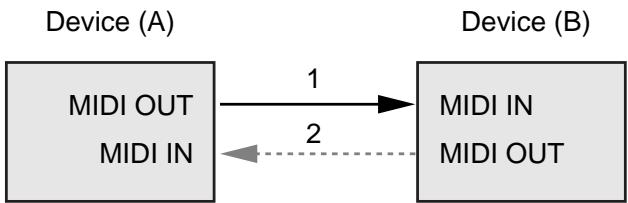
flowchart
graph LR
    A["MIDI OUT\nMIDI IN"] -->|1| B["MIDI IN\nMIDI OUT"]
    B -.->|2| A
Connection at point 2 is essential for "Request data" procedures. (See Section 3.)
Handshake-transfer procedure (This device does not use this procedure)
This procedure initiates a predetermined transfer sequence (handshaking) across the interface before data transfer takes place.
Handshaking ensures that reliability and transfer speed are high enough to handle a large amount of data.
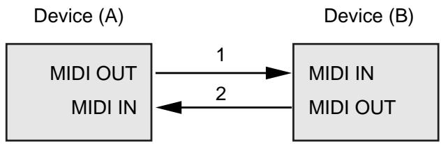
flowchart
graph LR
    A["MIDI OUT\nMIDI IN"] -->|1| B["MIDI IN\nMIDI OUT"]
    B -->|2| A
Connection at points 1 and 2 is essential.
MEMO
Notes on the above procedures
- There are separate Command IDs for different transfer procedures.
- Devices A and B cannot exchange data unless they use the same transfer procedure, share identical Device ID and Model ID, and are ready for communication.
3. One-way Transfer Procedure
This procedure sends out data until it has all been sent and is used when the messages are so short that answerbacks need not be checked.
For longer messages, however, the receiving device must acquire each message in time with the transfer sequence, which inserts 20 milliseconds intervals. In this method, as for the receiving device, it is necessary to receive data correctly in time.
Types of Messages
| Message | Command ID |
| Request data 1 | RQ1 (11H) |
| Data set 1 | DT1 (12H) |
Request data 1: RQ1 (11H)
This message is sent out when there is a need to acquire data from a device at the other end of the interface.
It contains data for the address and size that specify designation and length, respectively, of data required.
On receiving an RQ1 message, the remote device checks its memory for the data address and size that satisfy the request.
If it finds them and is ready for communication, the device will transmit a "Data set 1 (DT1)" message, which contains the requested data.
Otherwise, the device won't send out anything.
| Byte | Description |
| F0H | System Exclusive Status |
| 41H | Manufacturer ID (Roland) |
| DEV | Device ID |
| MDL | Model ID |
| 11H | Command ID |
| aaH | Address MSB |
| : | : |
| : | : |
| Address LSB | |
| ssH | Size MSB |
| : | : |
| : | : |
| Size LSB | |
| sum | Check sum |
| F7H | EOX (End of System Exclusive) |
MEMO
- The size of the requested data does not indicate the number of bytes that will make up a DT1 message, but represents the address fields where the requested data resides.
- Some models are subject to limitations in data format used for a single transaction. Requested data, for example, may have a limit in length or must be divided into predetermined address fields before it is exchanged across the interface.
- The same number of bytes comprises address and size data, which, however, vary with the Model ID.
- The error-checking process uses a checksum that provides a bit pattern where the last 7 bits are zero when values for an address, size, and that checksum are summed.
Data set 1: DT1 (12H)
This message corresponds to the actual data transfer process.
Because every byte in the data is assigned a unique address, a DT1 message can convey the starting address of one or more bits of data as well as a series of data formatted in an address-dependent order.
The MIDI standards inhibit non real-time messages from interrupting an Exclusive one. This fact is inconvenient for devices that support a “soft-thru” function.
To maintain compatibility with such devices, Roland has limited the DT1 to 256 bytes so that an excessively long message is sent out in separate 'segments.'
| Byte | Description |
| F0H | System Exclusive Status |
| 41H | Manufacturer ID (Roland) |
| DEV | Device ID |
| MDL | Model ID |
| 12H | Command ID |
| aaH | Address MSB |
| : | : |
| : | : |
| Address LSB | |
| ddH | Data MSB |
| : | : |
| : | : |
| Data LSB | |
| sum | Check sum |
| F7H | EOX (End of System Exclusive) |
MEMO
- A DT1 message is capable of providing only the valid data among those specified by an RQ1 message.
- Some models are subject to limitations in data format used for a single transaction. Requested data, or example, may have a limit in length or must be divided into predetermined address fields before it is exchanged across the interface.
- The number of bytes comprising address data varies from one Model ID to another.
- The error-checking process uses a checksum that provides a bit pattern where the last 7 bits are zero when values for an address, data, and that checksum are summed.
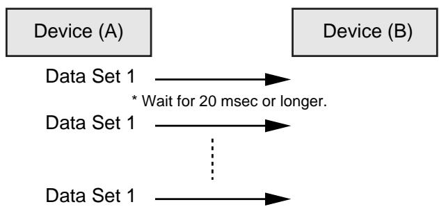
Example of Message Transactions
- Device A sending data to Device B Transfer of a DT1 message is all that takes place.
flowchart
graph LR
    A["Device (A)"] --> B["Device (B)"]
    A --> C["Data Set 1"]
    B --> D["Data Set 1"]
    C --> E["..."]
    D --> F["Data Set 1"]
    E --> G["Data Set 1"]
    style A fill:#f9f,stroke:#333
    style B fill:#f9f,stroke:#333
    style C fill:#ccf,stroke:#333
    style D fill:#ccf,stroke:#333
    style E fill:#ccf,stroke:#333
    style F fill:#cfc,stroke:#333
    note right of C: * Wait for 20 msec or longer.
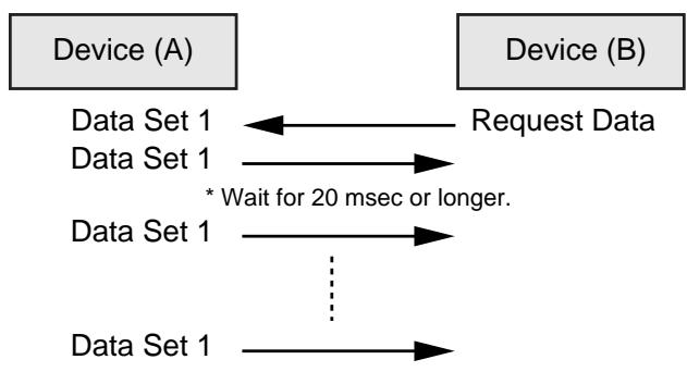
- Device B requesting data from Device A Device B sends an RQ1 message to Device A. Checking the message, Device A sends a DT1 message back to Device
flowchart
graph LR
    A["Device (A)"] -->|Request Data| B["Device (B)"]
    A --> C["Data Set 1"]
    B --> D["Data Set 1"]
    C --> E["* Wait for 20 msec or longer."]
    D --> F["..."]
    E --> G["..."]
    F --> H["Data Set 1"]
1. Recognized Receive Data
System Realtime Message
Active Sensing
| Status |
| FEH |
When FC-300 receives Active Sensing, it measures time intervals between incoming messages. If the subsequent message will not come within 400 msec after the previous one, FC-300 turns off Active Sensing for a period and stops measuring message intervals.
System Exclusive Message
| Status | Data | Status |
| F0H | iiH, ddH, ....., eeH | F7H |
| F0H | System Exclusive Status |
| ii | ID Number: The ID Number (manufacturer's ID) is used to distinguish one manufacturer's System Exclusive messages from another. Roland's manufacturer ID is 41H. ID Numbers 7EH and 7FH are used as Universal Non-realtime messages (7EH), and Universal Realtime message (7FH) for extending the MIDI standard. |
| dd, ..., ee | 00H-7FH (0-127) |
| F7H | EOX (End of System Exclusive) |
System Exclusive messages that the FC-300 can receive are Data Request (RQ1) and Data Set (DT1).
For a detailed explanation about Data Request (RQ1) and Data Set (DT1), refer to “Roland System Exclusive Messages” (p. 59) and “3. Exclusive Communications” (p. 64).
2. Transmitted Data
Transmitted Messages
Channel Voice Message
Note Off
| Status | Second | Third |
| 8nH | kkH | vvH |
| n = MIDI Channel Number | 0H-FH (ch.1-ch.16) |
| kk = Note Number | 00H-7FH (0-127) |
| vv = Velocity | 00H-7FH (0-127) |
* Specifically when Patch Mode is selected.
Note On
| Status | Second | Third |
| 9nH | kkH | vvH |
| n = MIDI Channel Number | 0H - FH (ch.1-ch.16) |
| kk = Note Number | 00H-7FH (0-127) |
| vv = Velocity | 01H-7FH (1-127) |
* Specifically when Patch Mode is selected.
Polyphonic Key Pressure
| Status | Second | Third |
| AnH | kkH | vvH |
| n = MIDI Channel Number | 0H - FH (ch.1-ch.16) |
| kk = Note Number | 00H-7FH (0-127) |
| vv = Polyphonic Key Pressure | 00H-7FH (0-127) |
* Specifically when Patch Mode is selected.
Control Change
| Status | Second | Third |
| BnH | ccH | vvH |
| n = MIDI Channel Number | 0H-FH (ch.1-ch.16) |
| cc = Control Number | 01H-1FH (1-31), 21H-5FH (33-95) |
| vv = Control Value | 00H-7FH (0-127) |
* Does not transmit while in System Exclusive Mode.
Bank Select
| Status | Second | Third |
| BnH | 00H | mmH |
| BnH | 20H | llH |
| n = MIDI Channel Number | 0H-FH (ch.1-ch.16) |
| mm = Upper bytes of Bank Select Number | 00H-7FH (0-127) |
| II = Lower bytes of Bank Select Number | 00H-7FH (0-127) |
* Specifically when Standard Mode and Patch Mode are selected.
Program Change
| Status | Second |
| CnH | ppH |
| n = MIDI Channel Number | 0H-FH (ch.1-ch.16) |
| pp = Program Number | 00H-7FH (prog.1-prog.128) |
* Specifically when Standard Mode and Patch Mode are selected.
Channel Pressure
| Status | Second |
| DnH | vvH |
| n = MIDI Channel Number | 0H - FH (ch.1-ch.16) |
| vv = Channel Pressure | 00H-7FH (0-127) |
* Does not transmit while in System Exclusive Mode.
Pitch Bend Change
| Status | Second | Third |
| EnH | llH | mmH |
| n = MIDI Channel Number | 0H - FH (ch.1-ch.16) |
| mm, II = Pitch Bend | 00 00H - 40 00H - 7F 7FH(-8192 - 0 - +8192) |
* Does not transmit while in System Exclusive Mode.
System Realtime Message
Start
| Status |
| FAH |
* Does not transmit while in System Exclusive Mode.
Continue
| Status |
| FBH |
* Does not transmit while in System Exclusive Mode.
Stop
| Status |
| FCH |
* Does not transmit while in System Exclusive Mode.
Active Sensing
| Status |
| FEH |
* During the normal operation, transmits at approx. 200 msec intervals.
* When message intervals are being monitored at the input section, the output of Active Sensing messages will cease for a certain period of time if the input interval exceeds 400 msec.
System Exclusive Message
| Status | Data | Status |
| F0H | iiH, ddH, ....., eeH | F7H |
| F0H | System Exclusive Status |
| ii = ID Number | 41H (65) |
| dd, ..., ee = data | 00H-7FH (0-127) |
| F7H | EOX (End of System Exclusive) |
For a detailed explanation, see “Roland System Exclusive Messages” (p. 59) and “3. Exclusive Communications” (p. 64).
MIDI Machine Control (MMC)
| Status | Data | Status |
| F0H | 7FH, 7FH, 06H, com | F7H |
| Byte | Description |
| F0H | System Exclusive Status |
| 7FH | ID Number (Universal Realtime Message) |
| 7FH | Device ID (Broadcast) |
| 06H | Sub-ID#1 (Machine Control Command) |
| com | Sub-ID#2 (MMC Command) |
| F7H | EOX (End of System Exclusive) |
* FC-300 can set the following MMC commands.
| com | |
| 01H | STOP |
| 02H | PLAY |
| 03H | DEFERRED PLAY |
| 04H | FAST FORWARD |
| 05H | REWIND |
| 06H | RECORD STROBE |
| 07H | RECORD EXIT |
| 08H | RECORD PAUSE |
| 09H | PAUSE |
* Does not transmit while in System Exclusive Mode.
3. Exclusive Communications
Using Roland's one-way System Exclusive message you can transfer data between FC-300 and another device.
You can use the following Model ID for the FC-300.
- 00H 00H 1EH (FC-300)
You can use System Exclusive messages to transmit and receive the FC-300's internal parameters in the form of bulk data.
• 00H 00H 20H (Foot Controller)
You can use System Exclusive messages to transmit and receive the FC-300's operational messages and display messages.
The Device ID can be set within the 00H to 1FH range.
For more on setting the Device ID, see “Réglage ‘Device ID’” (p. 52).
Request Data 1 RQ1 (11H)
| Byte | Description |
| F0H | System Exclusive Status |
| 41H | Manufacturer ID (Roland) |
| dev | Device ID (dev: 00H-0FH) |
| mdl | Model ID(mdl: 00H 00H 1EH) FC-300(mdl: 00H 00H 20H) Foot Controller |
| 11H | Command ID (RQ1) |
| aaH | Address MSB |
| bbH | Address LSB |
| ssH | Size MSB |
| ttH | Size LSB |
| sum | Checksum |
| F7H | EOX (End of System Exclusive) |
DATA SET 1 DT1 (12H)
| Byte | Description |
| F0H | System Exclusive Status |
| 41H | Manufacturer ID (Roland) |
| dev | Device ID (dev: 00H-0FH) |
| mdl | Model ID(mdl: 00H 00H 1EH) FC-300(mdl: 00H 00H 20H) Foot Controller |
| 12H | Command ID (DT1) |
| aaH | Address MSB |
| bbH | Address LSB |
| ddH | Data |
| : | : |
| eeH | Data |
| sum | Checksum |
| F7H | EOX (End of System Exclusive) |
4. Parameter Address Map (Model ID = 00H 00H 20H)
There are two types of the FC-300 System Exclusive message. FC-300 can send and receive the operation of this unit and display information by using the system exclusive message.
Address Block Map
| Address (H) | Block | Description |
| 10 00 | Mode Status | Read/Write |
| 20 00 | Pedal Status | Read |
| 30 00 | Pedal LED Status | Write |
| 40 00 | BANK/NUMBER Display Status | Write |
| 50 00 | Controller Status | Read/Write |
| 60 00 | Message Display Status | Write |
| 68 00 | Message Display User Font | Write |
| 70 00 | Tuner Display Status | Write |
| 71 00 | Tuner Pitch Status | Write |
Mode Status (Individual area)
| Address (H) | Size (H) | Data (H) | Parameter | Description |
| 10 00 | 00 01 | 00-01 | SYSEX Mode Status *1 | 0: Off, 1:On |
| 10 01 | 00 01 | 00-01 | SYSEX Mode Status *2 | 0: Off, 1:On |
| 10 02 | 00 01 | 00-01 | Function Mode Status *3 | 0: Play, 1:TUNER |
*1 Outputs on power-up or when Mode change is made.
Also outputs upon receiving Data Request (RQ1).
Data Set (DT1) is ignored.
*2 Mode Status is changed when Data Set (DT1) is received.
Changes the System Exclusive Mode when On is received.
MODE pedal is pressed same operation when Off is received in System Exclusive Mode.
*3 Changes the display of LCD in System Exclusive Mode when Data Set (DT1) is received.
Appears the received data in Message Display Status Address when PLAY is received.
Appears the TUNER screen and received data in Tuner Pitch Status Address when TUNER is received. (FC-300 has not TUNER function.)
Outputs when Data Request (RQ1) is received.
Pedal Status (Individual area)
| Address (H) | Size (H) | Data (H) | Parameter | Description |
| 20 00 | 00 01 | 00/7F | Pedal 1/6 Status | OFF/ON |
| 20 01 | 00 01 | 00/7F | Pedal 2/7 Status | OFF/ON |
| 20 02 | 00 01 | 00/7F | Pedal 3/8 Status | OFF/ON |
| 20 03 | 00 01 | 00/7F | Pedal 4/9 Status | OFF/ON |
| 20 04 | 00 01 | 00/7F | Pedal 5/10 Status | OFF/ON |
| 21 00 | 00 01 | 00/7F | CTL Pedal 1 Status | OFF/ON |
| 21 01 | 00 01 | 00/7F | CTL Pedal 2 Status | OFF/ON |
| 21 02 | 00 01 | 00/7F | CTL Pedal 4 Status | OFF/ON |
| 21 03 | 00 01 | 00/7F | CTL Pedal 6 Status | OFF/ON |
| 21 04 | 00 01 | 00/7F | CTL Pedal 8 Status | OFF/ON |
| 22 00 | 00 01 | 00/7F | EXP Pedal SW 1 Status | OFF/ON |
| 22 01 | 00 01 | 00/7F | EXP Pedal SW 2 Status | OFF/ON |
| 24 00 | 00 01 | 00-7F | EXP Pedal 1 Status | 0-127 |
| 24 01 | 00 01 | 00-7F | EXP Pedal 2 Status | 0-127 |
| 24 02 | 00 01 | 00-7F | CTL3/EXP3 Pedal Status | 0-127 |
| 24 03 | 00 01 | 00-7F | CTL5/EXP4 Pedal Status | 0-127 |
| 24 04 | 00 01 | 00-7F | CTL7/EXP5 Pedal Status | 0-127 |
| 25 00 | 00 01 | 00/7F | UP Pedal Status | OFF/ON |
| 25 01 | 00 01 | 00/7F | DOWN Pedal Status | OFF/ON |
- Outputs when pedal is operated while in the System Exclusive Mode.
- Also outputs Data Set (DT1) when Data Request (RQ1) is received.
• Data Set (DT1) is ignored.
LED Status (Individual area)
| Address (H) | Size (H) | Data (H) | Parameter | Description |
| 30 00 | 00 01 | 00/7F | Pedal 1/6 red LED Status | OFF/ON |
| 30 01 | 00 01 | 00/7F | Pedal 2/7 red LED Status | OFF/ON |
| 30 02 | 00 01 | 00/7F | Pedal 3/8 red LED Status | OFF/ON |
| 30 03 | 00 01 | 00/7F | Pedal 4/9 red LED Status | OFF/ON |
| 30 04 | 00 01 | 00/7F | Pedal 5/10 red LED Status | OFF/ON |
| 30 05 | 00 01 | 00/7F | Pedal 1/6 green LED Status | OFF/ON |
| 30 06 | 00 01 | 00/7F | Pedal 2/7 green LED Status | OFF/ON |
| 30 07 | 00 01 | 00/7F | Pedal 3/8 green LED Status | OFF/ON |
| 30 08 | 00 01 | 00/7F | Pedal 4/9 green LED Status | OFF/ON |
| 30 09 | 00 01 | 00/7F | Pedal 5/10 green LED Status | OFF/ON |
| 31 00 | 00 01 | 00/7F | CTL Pedal 1 LED Status | OFF/ON |
| 31 01 | 00 01 | 00/7F | CTL Pedal 2 LED Status | OFF/ON |
| 32 00 | 00 01 | 00/7F | EXP Pedal SW 1 LED Status | OFF/ON |
| 32 01 | 00 01 | 00/7F | EXP Pedal SW 2 LED Status | OFF/ON |
| 35 00 | 00 01 | 00/7F | UP Pedal LED Status | OFF/ON |
| 35 01 | 00 01 | 00/7F | DOWN Pedal LED Status | OFF/ON |
- Receives Data Set (DT1) in all mode, changes the LED status of each pedal only in the System Exclusive Mode.
• Data Request (RQ1) is ignored.
BANK/NUMBER Display Status (Individual area)
| Address (H) | Size (H) | Data (H) | Parameter | Description |
| 40 00 | 00 02 | 0abcdefg, 0000000h | Right | 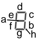 |
| 40 02 | 00 02 | 0abcdefg, 0000000h | Center | |
| 40 04 | 00 02 | 0abcdefg, 0000000h | Left |
- Receives Data Set (DT1) in all mode, changes the BANK/NUMBER display status only in the System Exclusive Mode.
- Each bit represents ON/OFF of corresponding display segment. Bit "0" = OFF; "1" = ON
• Data Request (RQ1) is ignored.
Controller Status (Individual area)
| Address (H) | Size (H) | Data (H) | Parameter | Description |
| 50 00 | 00 01 | 00/7F | AMP CON-TROL 1 Status | OFF/ON |
| 50 01 | 00 01 | 00/7F | AMP CON-TROL 2 Status | OFF/ON |
• Receives Data Set (DT1) in all mode.
- Changes status of AMP CONTROL jack when Data Set (DT1) is received.
- Outputs when Data Request (RQ1) is received.
Message Display Status (Individual area)
| Address (H) | Size (H) | Data (H) | Parameter | Description |
| 60 00 | 00 10 | 00-07,20-7D | Line 0Column 0 data | 00-07: User Font20-7D: ASCII characters |
| : | : | : | ||
| 60 0F | 00-07,20-7D | Line 0Column 15 data | ||
| 64 00 | 00 10 | 00-07,20-7D | Line 1Column 0 data | |
| : | : | : | ||
| 64 0F | 00-07,20-7D | Line 1Column 15 data |
• Receives Data Set (DT1) in all mode.
- Outputs when Data Request (RQ1) is received.
Message Display User Font (Individual area)
| Address (H) | Size (H) | Data (H) | Parameter | Description |
| 68 00 | 00 08 | 00-1F | User Font 1Line 0 data | *1 |
| : | : | : | ||
| 68 07 | 00-1F | User Font 1Line 7 data | ||
| 68 08 | 00 08 | 00-1F | User Font 2Line 0 data | |
| : | : | : | : | |
| 68 38 | 00 08 | 00-1F | User Font 8Line 7 data |
- Receives Data Set (DT1) in all mode, changes the user font of the LCD only in the System Exclusive Mode.
• Data Request (RQ1) is ignored.
*1 The bitmap data of the user font following displayed in LCD.
| Parameter | Data |
| User Font line0 data | 000xxxxx |
| User Font line1 data | 000xxxxx |
| User Font line2 data | 000xxxxx |
| User Font line3 data | 000xxxxx |
| User Font line4 data | 000xxxxx |
| User Font line5 data | 000xxxxx |
| User Font line6 data | 000xxxxx |
| User Font line7 data | 000xxxxx |
Tuner Display Status (Individual area)
| Address (H) | Size (H) | Data (H) | Parameter | Description |
| 70 01 | 00 01 | 00/7F | C#/DbDisplay Status | C#/Db |
| 70 02 | 00 01 | 00/7F | D#/EbDisplay Status | D#/Eb |
| 70 03 | 00 01 | 00/7F | F#/GbDisplay Status | F#/Gb |
| 70 04 | 00 01 | 00/7F | G#/AbDisplay Status | G#/Ab |
| 70 05 | 00 01 | 00/7F | A#/BbDisplay Status | A#/Bb |
- Receives Data Set (DT1) in all mode, changes the display of the LCD when only Function Mode Status is TUNER.
• Data Request (RQ1) is ignored.
Tuner Pitch Status (Individual area)
| Address (H) | Size (H) | Data (H) | Parameter | Description |
| 71 00 | 00 01 | 00, 01-06 | String Number | 00: OFF01: 1-6 |
| 71 01 | 00 01 | 00, 01-0D | Tuner Note Status | 00: No Signal01: C, 02: C#03: D, 04: D#05: E, 06: F07: F#, 08: G09: G#, 0A: A0B: A#, 0C: B |
| 71 02 | 00 01 | 00, 01-40-7F | Tuner Cent Status | 00: No Signal01: -5040: 07F: 50 |
- Receives Data Set (DT1) when only Function Mode Status is TUNER.
- Changes the display of the LCD when Data Set (DT1) is received.
• Data Request (RQ1) is ignored.
Mode 1: OMNI ON, POLY
Mode 2: OMNI ON, MONO
o: Yes
Mode 3: OMNI OFF, POLY
Mode 4: OMNI OFF, MONO
x: No
FC-300: PÉDALIER MIDI
RRC2 Buffer Full! 57
RRC2 Offline! 57
Index
RRC2 OUT 10
s
Sauvegarder 44
Set to MAX 56
Set to MIN 56
Standard 14,16
Supprimer 40
SYS 46
SysEx 59
System 46
System Exclusive 14,59
T
Threshold 56
Tx Channel 52
U
UTILITY 8
V
VALUE 8
W
Write 8,44
IMPORTANT: THE WIRES IN THIS MAINS LEAD ARE COLOURED IN ACCORDANCE WITH THE FOLLOWING CODE.
BLUE: NEUTRAL
BROWN: LIVE
As the colours of the wires in the mains lead of this apparatus may not correspond with the coloured markings identifying the terminals in your plug, proceed as follows:
The wire which is coloured BLUE must be connected to the terminal which is marked with the letter N or coloured BLACK. The wire which is coloured BROWN must be connected to the terminal which is marked with the letter L or coloured RED.
Under no circumstances must either of the above wires be connected to the earth terminal of a three pin plug.

This equipment has been tested and found to comply with the limits for a Class B digital device, pursuant to Part 15 of the FCC Rules. These limits are designed to provide reasonable protection against harmful interference in a residential installation. This equipment generates, uses, and can radiate radio frequency energy and, if not installed and used in accordance with the instructions, may cause harmful interference to radio communications. However, there is no guarantee that interference will not occur in a particular installation. If this equipment does cause harmful interference to radio or television reception, which can be determined by turning the equipment off and on, the user is encouraged to try to correct the interference by one or more of the following measures:
— Reorient or relocate the receiving antenna.
— Increase the separation between the equipment and receiver.
— Connect the equipment into an outlet on a circuit different from that to which the receiver is connected.
— Consult the dealer or an experienced radio/TV technician for help.
This device complies with Part 15 of the FCC Rules. Operation is subject to the following two conditions:
this device may not cause harmful interference, and
this device must accept any interference received, including interference that may cause undesired operation.
Unauthorized changes or modification to this system can void the users authority to operate this equipment.
This equipment requires shielded interface cables in order to meet FCC class B Limit.
Pour le Canada
NOTICE
This Class B digital apparatus meets all requirements of the Canadian Interference-Causing Equipment Regulations.
AVIS
9, EBN Hagar A1 Askalany Street,
ARD E1 Golf, Heliopolis,
Cairo 11341, EGYPT TEL: 20-2-417-1828
REUNION
Royal Cape Park, Unit 24
Londonderry Road, Ottery 7800
Cape Town, SOUTH AFRICA
TEL: (021) 799 4900
ASIA
CHINA
Roland Shanghai Electronics
Co., Ltd.
5F. No.1500 Pingliang Road
Shanghai 200090, CHINA
TEL: (021) 5580-0800
Roland Shanghai Electronics
Co., Ltd.
(BEIJING OFFICE)
10F. No.18 3 Section Anhuaxili
Chaoyang District Beijing
100011 CHINA TEL: (010) 6426
HONG KONG
Tom Lee Music Co., Ltd.
Service Division
22-32 Pun Shan Street, Tsuen
Wan, New Territories,
HONG KONG
TEL: 2415 0911
Parsons Music Ltd.
8th Floor, Railway Plaza, 39
Chatham Road South, T.S.T,
Kowloon, HONG KONG TEL: 2222-1862
TEL: 2333 1863
INDIA
Rivera Digitec (India) Pvt. Ltd.
409, Nirman Kendra
Mahalaxmi Flats Compound
Off. Dr. Edwin Moses R Mumbai 400011 INDIA
Mumbai-400011, INI TEI · (022) 2493 9051
INDONESIA
PT Citra IntiRama
J1. Cideng Timur No. 15J-150
Jakarta Pusat
INDONESIA
TEL: (021) 6324170
KOREA
Cosmos Corporation
1461-9, Seocho-Dong,
Seocho Ku, Seoul, KOREA
TEL: (02) 3486-8855
MALAYSIA
Roland Asia Pacific Sdn. Bhd.
45-1, Block C2, Jalan PJU 1/39,
Dataran Prima, 47301 Petaling Java Selangor MALAYSIA
Jaya, Selangor, MALAYSIA TEL: (02) 7805 3262
TEL: (05) 7805-5265
PHILIPPINES
G.A. Yupangco & Co. Inc.
339 Gil J. Puyat Avenue
Makati, Metro Manila 1200,
PHILIPPINES
TEL:(02) 899 9801
SINGAPORE
SWEE LEE MUSIC
COMPANY PTE. LTD.
150 Sims Drive,
SINGAPORE 387381
TEL: 6846-3676
TAIWAN
ROLAND TAIWAN
ENTERPRISE CO., LTD.
Room 5, 9fl. No. 112 Chung
Shan N.Road Sec.2, Taipei,
TAIWAN, R.O.C. TEL: (02) 2561 3229
THAILAND
Theera Music Co., Ltd.
330 Soi Verng NakornKasem,
New Road, Sumpantawongse,
Bangkok 10100, THAILAND TEL: (02) 224-8821
AUSTRALIA/ NEW ZEALAND
AUSTRALIA/
NEW ZEALAND
Roland Corporation
Australia Pty., Ltd.
38 Campbell Avenue
Dee Why West. NSW 2099
AUSTRALIA
For Australia
Tel: (02) 9982 8266
For New Zealand
Tel: (09) 3098 715
CENTRAL/LATIN AMERICA
ARGENTINA
Instrumentos Musicales S.A.
Av.Santa Fe 2055
(1123) Buenos Aires
ARGENTINA TEL: (011) 459
TEL: (011) 4508-2700
BARBADOS
A&B Music Supplies LTD
12 Webster Industrial Park
Wildey, St.Michael, Barbados TEL: (216) 128-1122
TEL: (246)430-1100
BRAZIL
Roland Brasil Ltda.
Rua San Jose, 780 Sala B
Parque Industrial San Jose
Cotia - Sao Paulo - SP, BRAZIL
TEL: (011) 4615 5666
CHILE
Comercial Fancy II S.A.
Rut.: 96.919.420-1
Nataniel Cox #739, 4th Floor
Santiago - Centro, CHILE
TEL: (02) 688-9540
COLOMBIA
Centro Musical Ltda.
Cra 43 B No 25 A 41 Bododega 9
Medellin, Colombia
TEL: (574)3812529
COSTA RICA
JUAN Bansbach Instrumentos
Musicales
Boulevard Andrews, Albrook,
Panama City, REP. DE
PANAMA TEL: 315-0101
TEL: 315-0101
PARAGUAY
Distribuidora De
Instrumentos Musicales
J.E. Olear y ESQ. Manduvira
Asuncion PARAGUAY TEL: (505) 21 492147
TEL: (595) 21 492147
PERU
Audionet
155, New National Road
Patras 26442, GREECE
TEL: 2610 435400
HUNGARY
Roland East Europe Ltd.
Warehouse Area 'DEPO' Pf.83
H-2046 Torokbalint, HUNGARY
HUNGARY TEL: (23) 511
TEL. (23) 511011
IRELAND
Roland Ireland
G2 Calmount Park, Calmount
Avenue, Dublin 12