
GYB00816ST - Boiler AEG - Free user manual and instructions
Find the device manual for free GYB00816ST AEG in PDF.


| Product type | Wall-mounted condensing boiler |
| Brand | AEG |
| Model | GYB00816ST |
| Dimensions (H x W x D) | 700 x 400 x 300 mm |
| Net weight | 35 kg |
| Power supply | 230 V / 50 Hz |
| Heating power (Pmax) | 28 kW |
| Energy class | A+ (according to EU regulation 811/2013) |
| Fuel type | Natural gas (G20/G25) |
| Maximum water pressure | 3 bar |
| Heating temperature range | 30 - 80 °C |
| Main functions | Central heating, domestic hot water production, time programming, summer/winter function |
| Maintenance and cleaning | Annual maintenance recommended by a professional, cleaning of burner and heat exchanger |
| Safety | Anti-freeze, overheat protection, lack of water, integrated safety gas valve |
| Available spare parts | Gas filter, circulation pump, electrodes, expansion vessel, thermocouple |
| Repairability index | 7.5/10 (manufacturer data) |
| Manufacturer warranty | 2 years (parts and labor) |
| Country of origin | Germany |
Frequently Asked Questions - GYB00816ST AEG
User questions about GYB00816ST AEG
0 question about this device. Answer the ones you know or ask your own.
Ask a new question about this device
Download the instructions for your Boiler in PDF format for free! Find your manual GYB00816ST - AEG and take your electronic device back in hand. On this page are published all the documents necessary for the use of your device. GYB00816ST by AEG.
USER MANUAL GYB00816ST AEG
1 Main components of the complete system

2 Parts description
3 Before installation
4 Overview Solo Situation

5 Overview Combi Situation
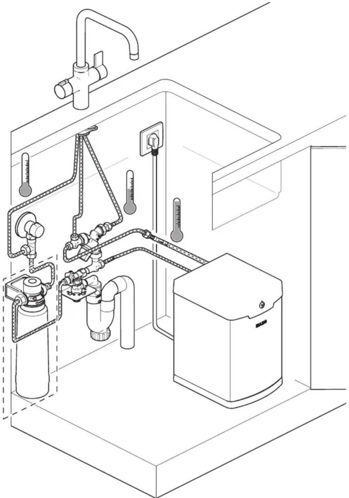
6 The tap Installed
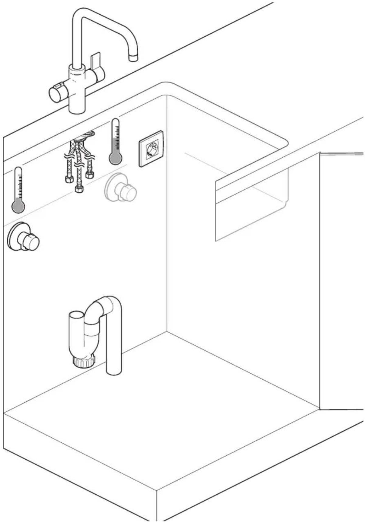
7 The filter installed (optional)
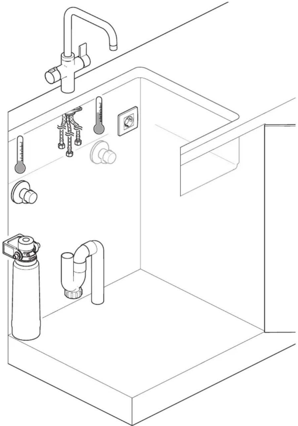
8 Attach t-piece to cold water supply

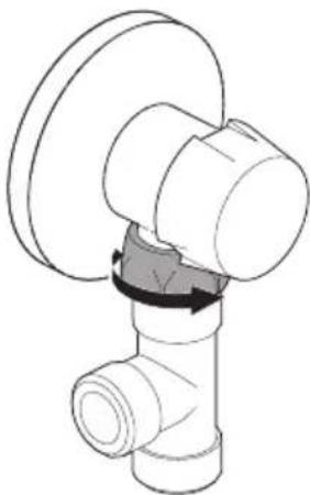

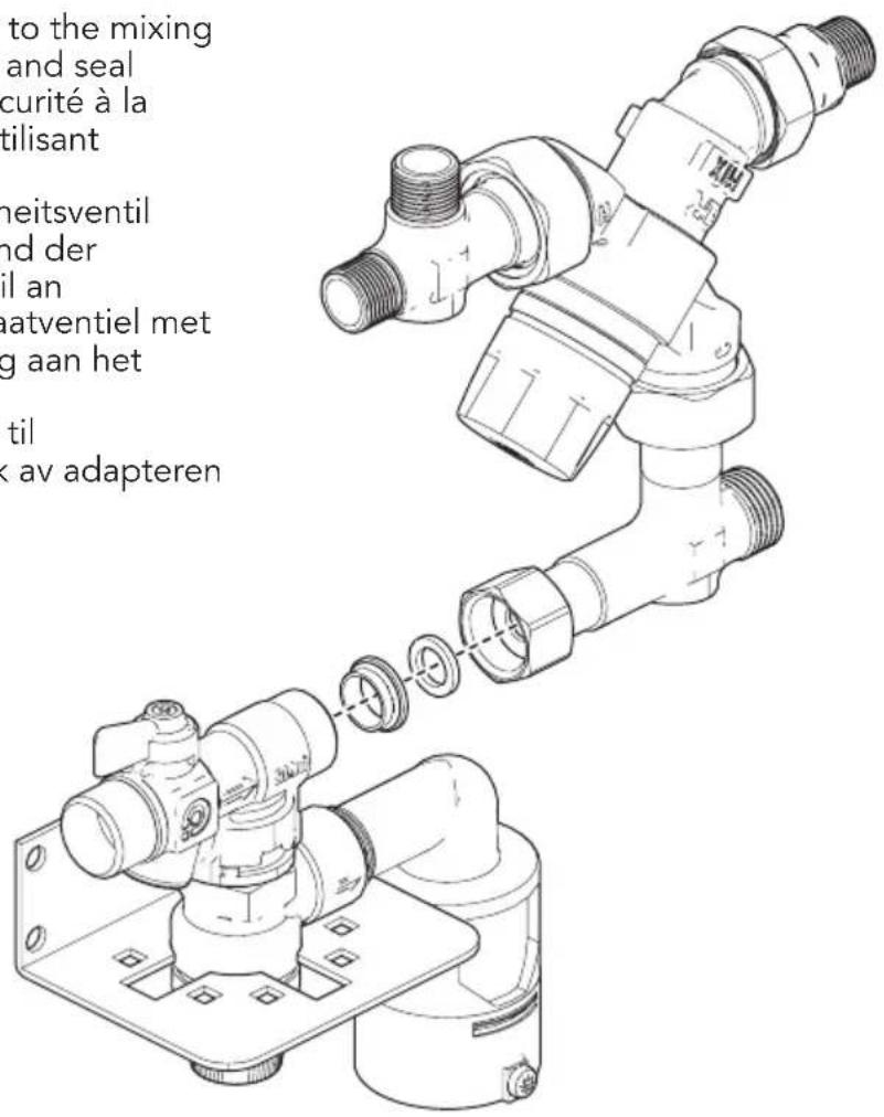
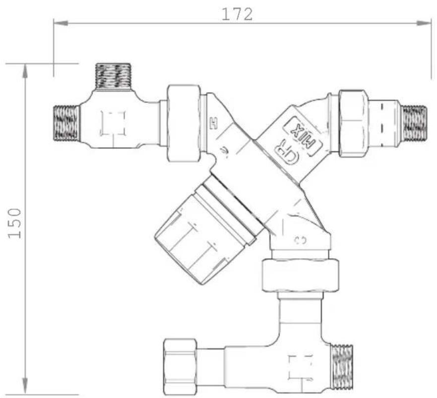
11 Attach the safety valve to the mixing valve using the adapter and seal
14 Connect filter hose
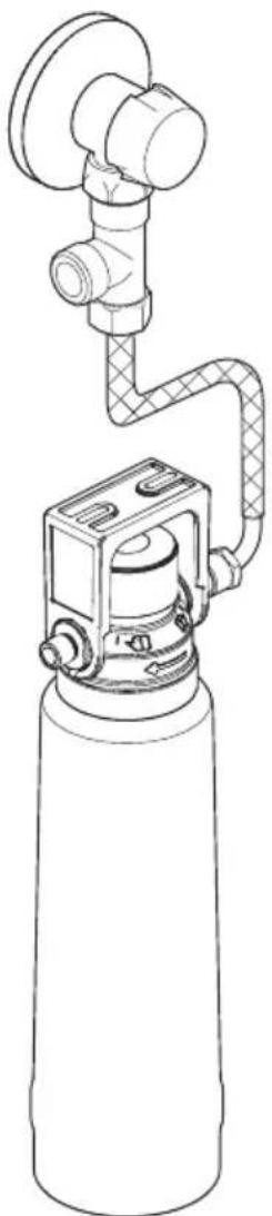
15 Connect cold water hose to filter and pressure safety valve
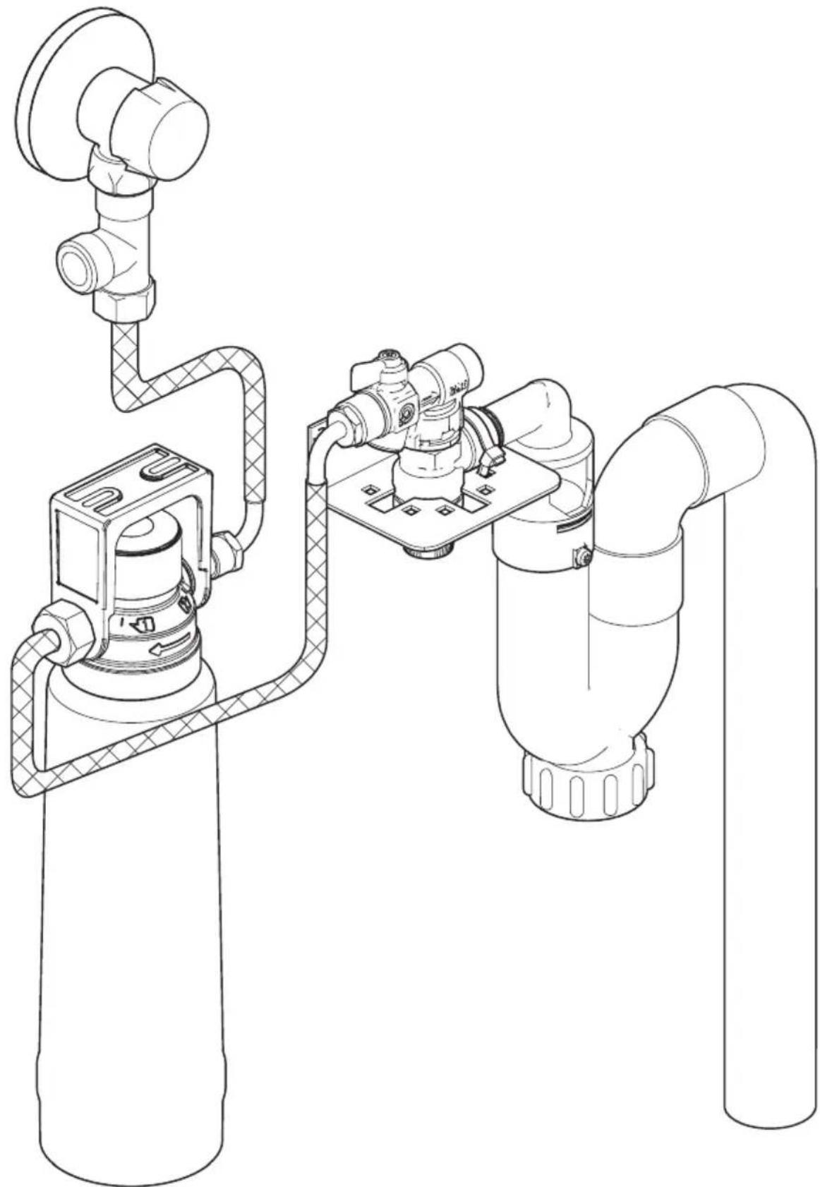
16 Connect cold water hose to t-piece and safety valve (situation without filter)
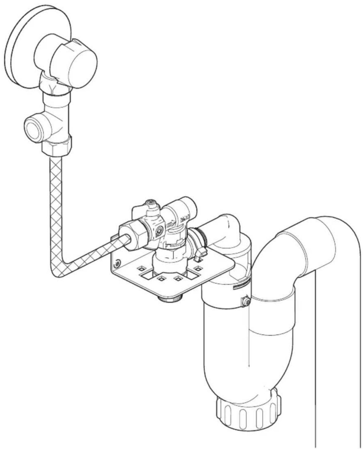
17 Connect cold water inlet boiler to pressure safety valve
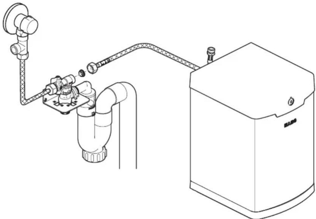
18 Connect cold water inlet boiler to mixing valve
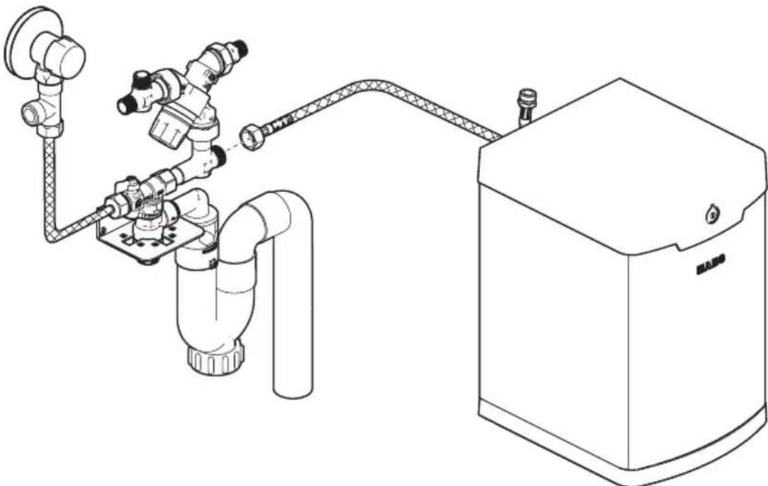
19 Connect boiling water hose boiler to boiling water inlet tap
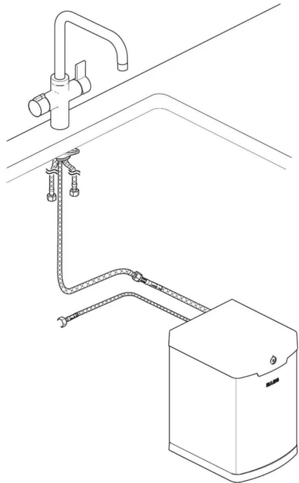
20 Connect boiling water extension hose
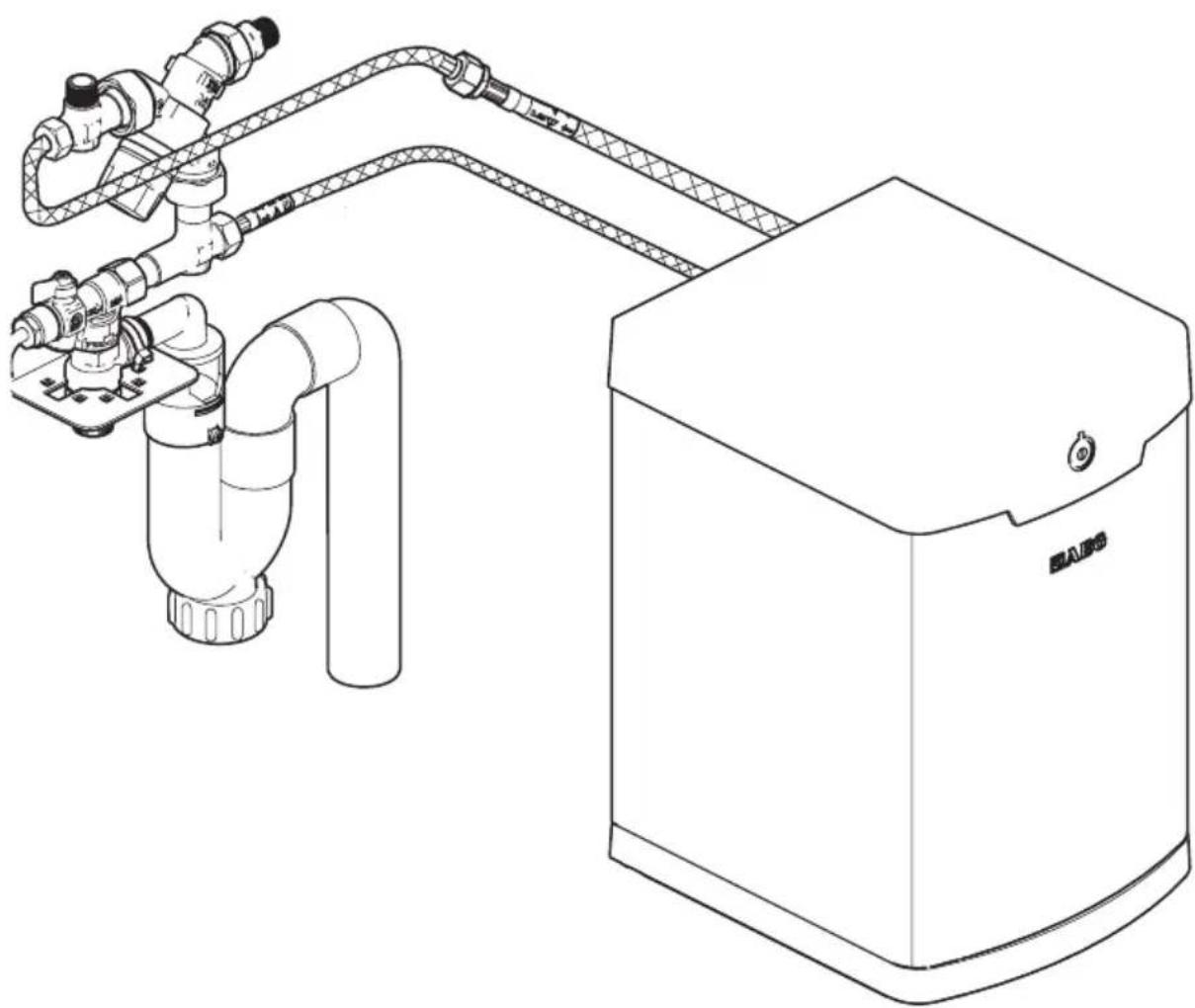
21 Connect boiling water inlet tap to mixing valve
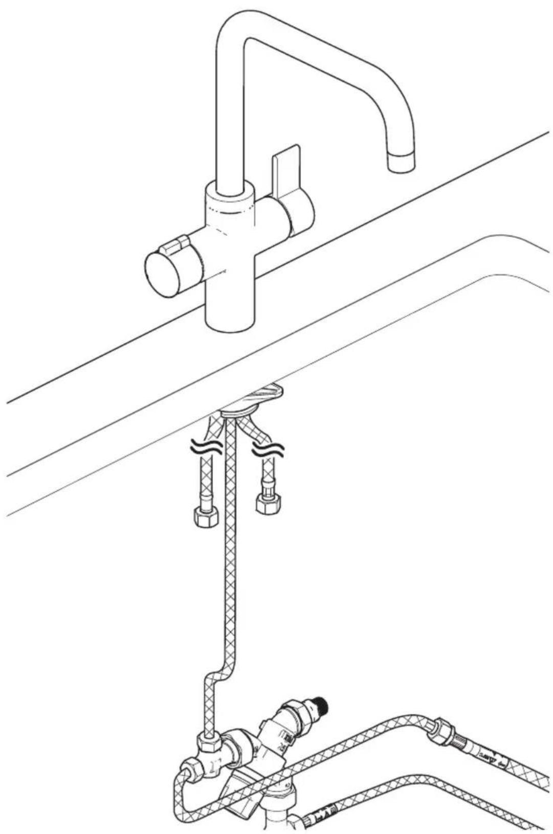
22 Connect cold water inlet tap to t-piece
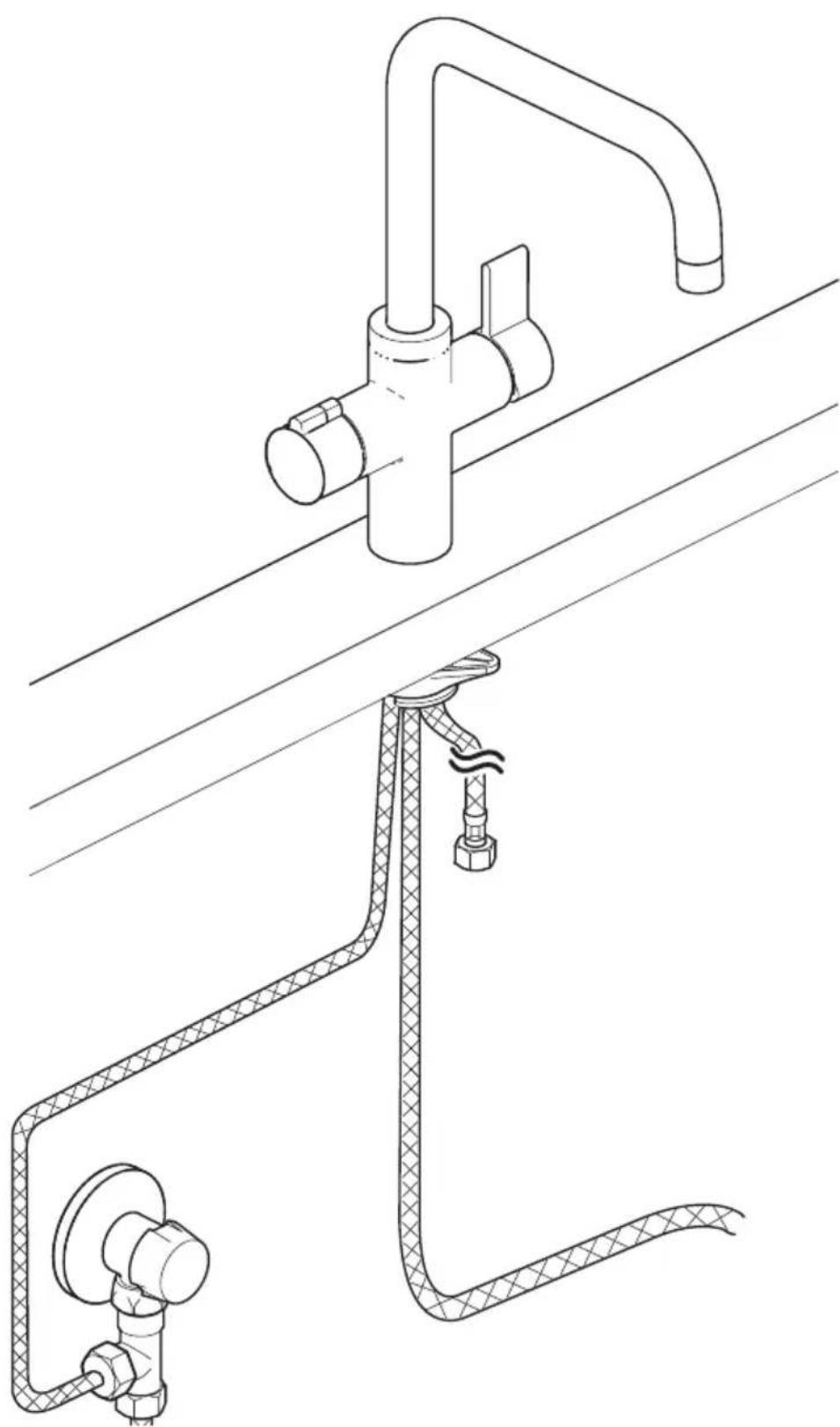
23 Connect warm water inlet tap to warm water supply
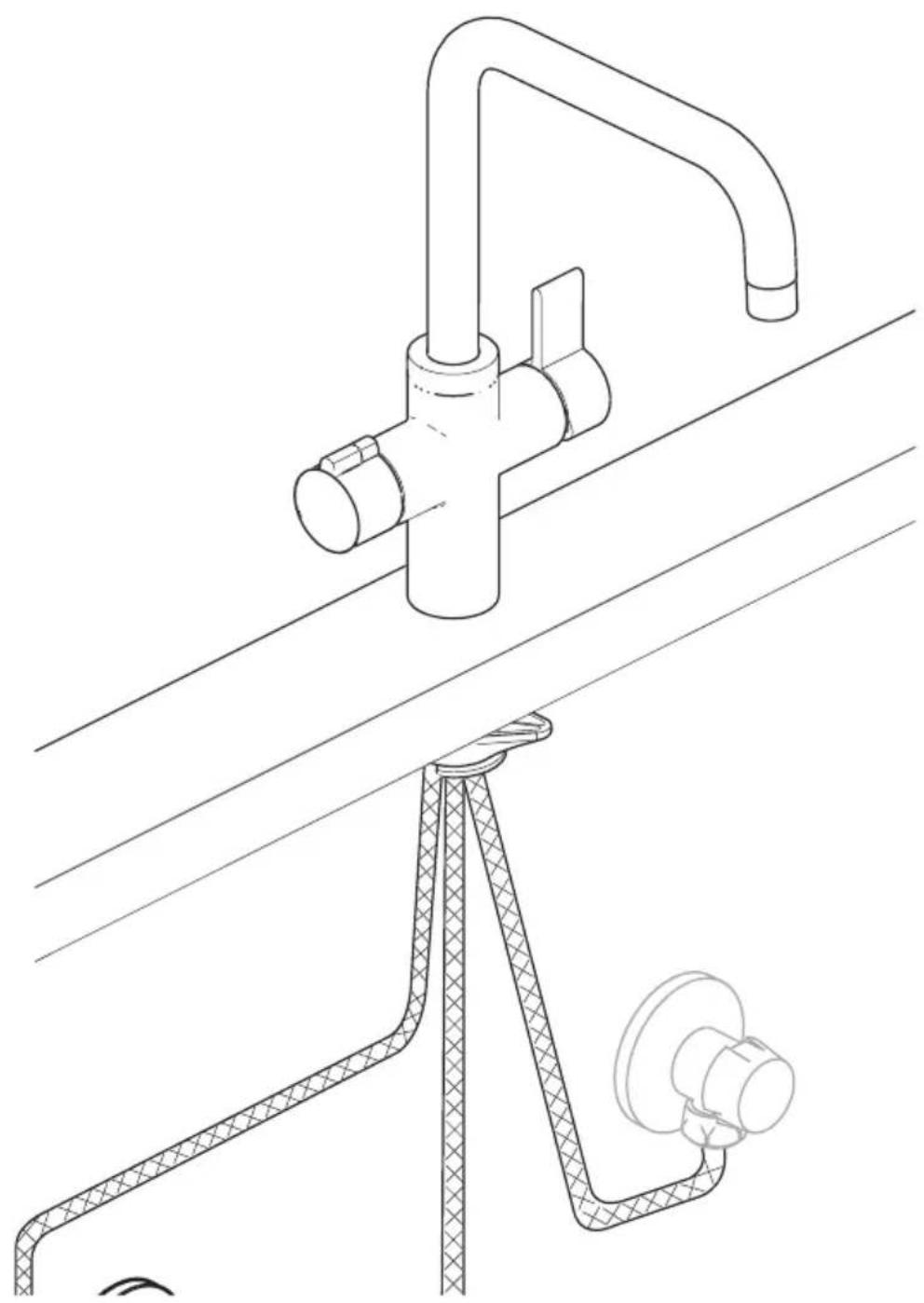
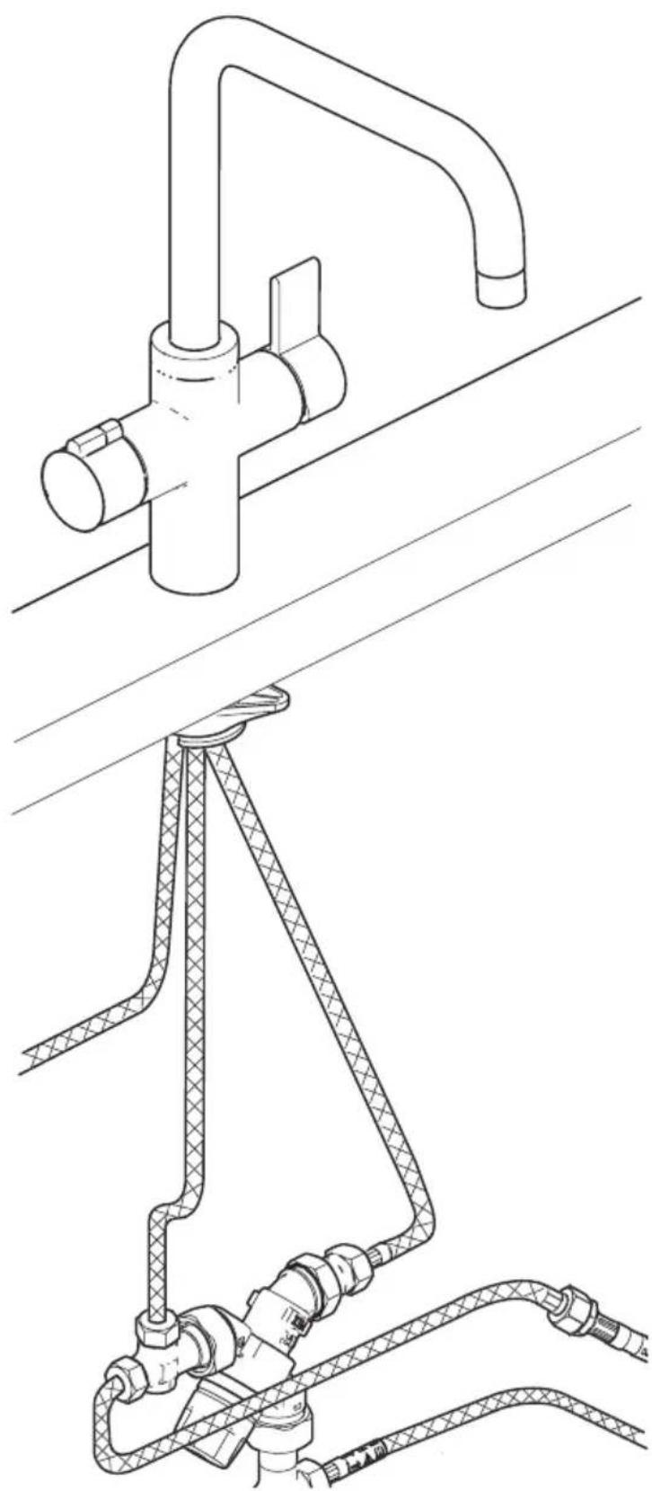
24 Connect warm water inlet tap to warm water outlet mixing valve
25 Use boiling water handle
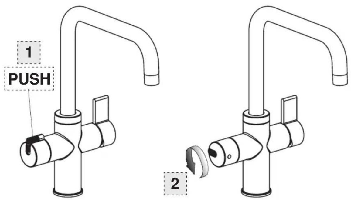
26 Use mixing handle 1
27 Use mixing handle 2
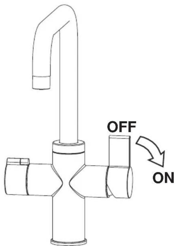
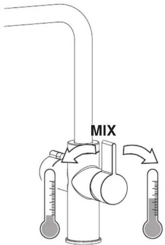
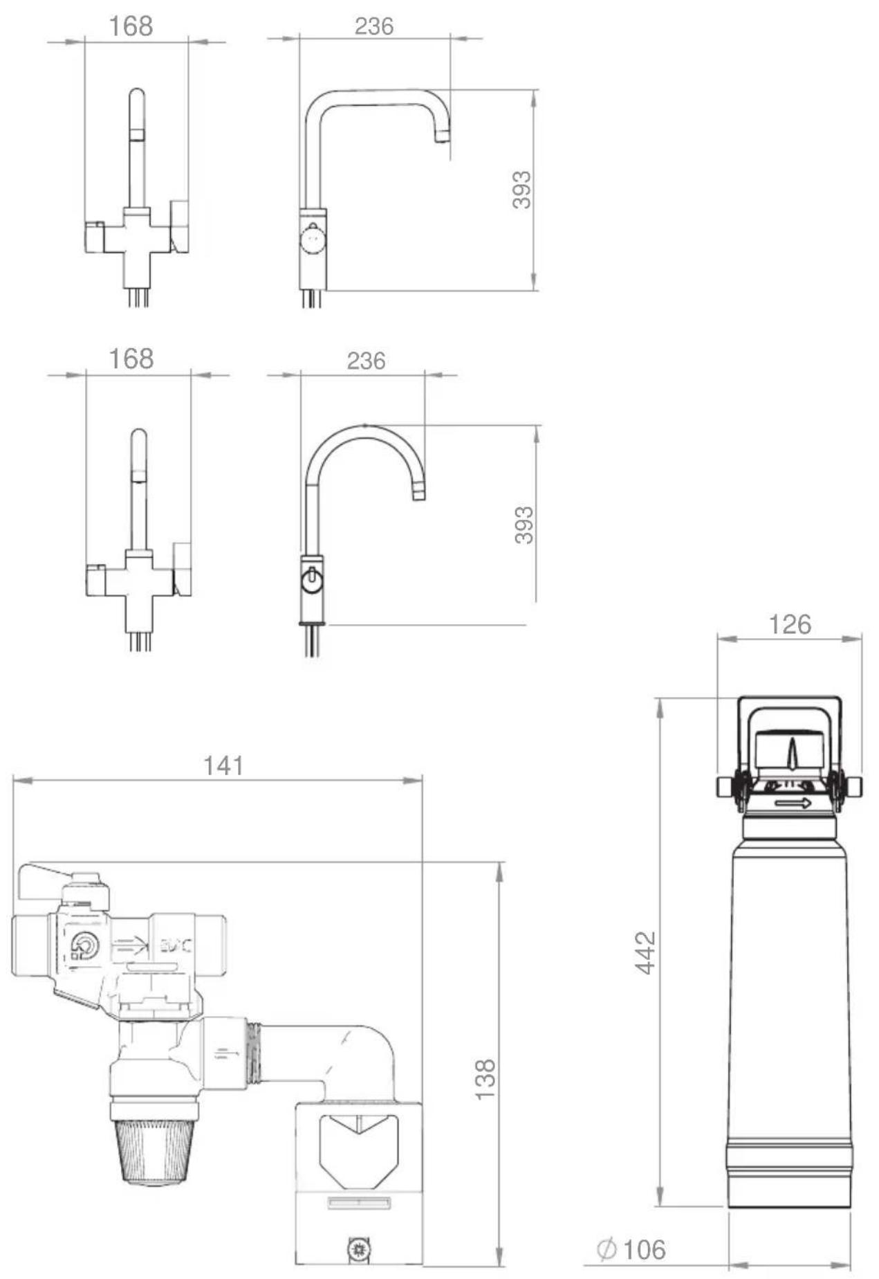
28 Built-in dimensions

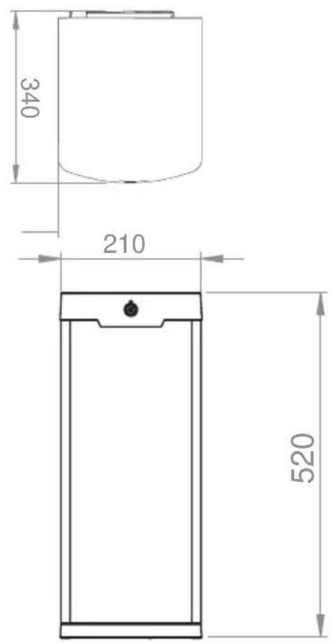
CONTENTS
- INTRODUCTION....27
- SAFETY INFORMATION ....28
- PRODUCT DESCRIPTION .... 31
- INSTALLATION....34
- DAILY USE 38
- MAINTENANCE, CARE AND CLEANING....40
- TROUBLESHOOTING ....40
- TECHNICAL INFORMATION ....42
FOR PERFECT RESULTS
Thank you for choosing this AEG product. We have created it to give you impeccable performance for many years, with innovative technologies that help make life simpler – features you might not find on ordinary appliances. Please spend a few minutes reading to get the very best from it.
Visit our website to:

Get usage advice, brochures, trouble shooter, service information: www.aeg.com

Register your product for better service: www.registeraeg.com

Buy Accessories, Consumables and Original spare parts for your appliance: www.aeg.com/shop
CUSTOMER CARE AND SERVICE
Always use original spare parts.
When contacting our Authorised Service Centre, ensure that you have the following data available: Model, PNC, Serial Number.
The information can be found on the rating plate.

Warning / Caution-Safety information.

General information and tips.

Environmental information.
Subject to change without notice.
1. INTRODUCTION
1.1 Intended use and unintended use
This AEG appliance is intended to be used to store, heat and provide drinking water. The appliance should only be used in household and similar environments, such as:
• In shops, offices and other similar working environments; • In farm houses; - By clients in hotels, motels and other residential type environments; • In bed and breakfast type environments.
The appliance should not be used:
- For commercial or industrial purposes; • In vehicles or on board ships or aircraft; • In locations with a corrosive or explosive atmosphere; • For medical purposes;
The appliance may only be used according to the instructions described in this manual. Any use other than described in this manual is considered unintended use.
1.2 General working principle
This AEG appliance stores, heats, and provides boiling drinking water in addition to cold and warm water.
To supply boiling water, cold water flows from the cold water supply to the boiler, where it is heated to 100 °C. From the boiler, the boiling water flows to the tap.
The cold water also flows from the cold water supply directly to the cold water inlet on the tap.
There are two ways to provide the tap with warm water:
– Warm water can be supplied by connecting the warm water supply, if available, to the warm water inlet on the tap. This situation is named the solo configuration. – Cold water and boiling water from the boiler can be mixed with the mixing valve. The mixed water outlet of the mixing valve can be connected to the warm water inlet on the tap. This situation is named the combi configuration.
1.3 Article numbers
The table below describes the available components of the appliance.
| Main parts Type Article number | ||
| Boiler 4 litres GYB00416ST | ||
| 8 litres GYB00816ST | ||
| Tap Curve – Chrome finish GYT11012CB | ||
| Square – Chrome finish GYT12012CB | ||
| Curve – Stainless steel finish GYT11012SB | ||
| Square – Stainless steel finish GYT12012SB | ||
| Pressure safety valve 8 bar GYB08016XA | ||
| 10 bar GYB10016XA | ||
| Mixing valve (for combi configuration only) | GYBMIX16XA | |
| Filter installation kit (optional) | Includes filter, filter head, filter hose and flow meter | A2HK0001 |
| Replacement water filter (optional) | A3HW0001 | |
2. SAFETY INFORMATION
2.1 Introduction
Before the installation and use of the appliance, carefully read the supplied instructions. Refer to the separate manuals supplied with the other components for other relevant information.
The manufacturer is not responsible if incorrect installation and/or use causes injuries and damages. Always keep the instructions with the appliance for future reference. The information in this manual is subject to change without notice.
2.2 Children and vulnerable people safety

WARNING! Risk of suffocation, injury or permanent disability.
- The appliance should not be used by children younger than 8 years.
- Children aged from 8 years and above must be supervised or instructed concerning the use of the appliance in a safe way and must understand the hazards involved.
- Persons with reduced physical, sensory or mental capabilities or lack of experience and knowledge must be supervised or instructed concerning the use of the appliance in a safe way and must understand the hazards involved.
- Children must be supervised to ensure that they do not play with the appliance.
- The appliance contains hot parts. Ensure that children do not have access to the appliance and lock possible access doors.
- Keep all packaging away from children.
2.3 Installation
- Only qualified, certified personnel may install the appliance. • Always remove all the packaging before installing the appliance.
- Do not install or use a damaged appliance.
- Do not install or use the appliance in a place where the temperature is less than 0 °C.
- The appliance is suitable for indoor use only.
- Do not install the appliance at an altitude of more than 2000 metres above sea level.
- Risk of scalding! An unstable work environment and air pressure differences may cause uncontrolled splashing of boiling water or developing steam. The appliance should not be installed in vehicles like boats or airplanes.
- Do not install the appliance in locations with a corrosive or explosive atmosphere.
- Only install the appliance according to the instructions described in this manual. Do not use extension hoses other than those provided with the appliance.
- The appliance may only be used together with the original AEG tap.
- Make sure to place all parts correctly and according to the instructions. Failure to do so may affect the proper functioning of the product.
- Unauthorized alterations to the appliance and technical modifications are not permitted.
2.4 Water connection
- Install a pressure reducing valve if the water pressure of the water supply exceeds the maximum allowed water pressure of the pressure safety valve. Refer to the section TECHNICAL INFORMATION for the maximum allowed water pressure of the pressure safety valve.
- Improper installation of the appliance can cause property damage. Observe the national installation regulations (e.g. EN 1717:2000), general hygiene conditions and technical data for the protection of the drinking water.
2.5 Electrical connection

WARNING! Risk of fire and electrocution!
- The appliance must be connected to a permanent and earthed AC wall socket (with 16A fuse).
- Electrical installation work must only be performed by a qualified electrician. This work must be carried out in accordance with all national and local regulations.
- Extension cables and multi-plug adapters are not permitted between the earthed AC wall socket and the plug of the boiler.
- Make sure the plug of the boiler and the power cable are not damaged. Contact the manufacturer or an electrician if parts are damaged.
- Connect the plug of the boiler to the earthed AC wall socket only at the end of the installation. Make sure that there is access to the plug and earthed AC wall socket after the installation. See the chapter "Installation".
2.6 Pressure safety valve installation
- Leave the outlet of the pressure-relief device open to the atmosphere so water may drip from the discharge pipe.
- The pressure safety valve is available in two different types (8 bar and 10 bar). Make sure you install the correct pressure safety valve, based on national and/or local regulations.
2.7 Filter installation
- A filter can be installed to reduce the hardness and/or chlorine values. The relevant water supplier can provide information on the hardness and chlorine value. AEG recommends using a filter if the hardness is more than 10 °DH.
- For hygiene reasons, the filter system must be flushed before using for the first time. Refer to the filter manual for information about flushing the filter.
- The filter installation kit and replacement water filter cartridges can be ordered online at shop.aeg.com, part code: 9029795565.
2.8 Use

WARNING!
Risk of scalding!
- Water can be very hot. Always turn on the tap carefully to prevent splashing.
- Only open the tap when placed directly above the sink to prevent splashing.
- Only use tap water in products which are (boiling) water resistant. Not all materials are boiling water resistant and this can lead to permanent deformation of the product or to serious injury.
- Wear protective equipment like oven gloves or pot-holders when you fill
products with boiling water.
- Use the appliance only for its intended use as described in this manual.
- Make sure the plug of the boiler and the power cable are not damaged when using the appliance. Contact the manufacturer or an electrician if parts are damaged.
- Clean the appliance regularly according to the instructions in this manual.
- Unauthorized alterations to the appliance and technical modifications are not permitted.
2.9 Care and cleaning
- The boiler and plug must not be directly or indirectly sprayed with water when cleaning.
- Clean the appliance with a dry, lint-free cloth. Do not use detergents or other solvents to clean the appliance.
2.10 Repair, disassemble, discard
- Only qualified, certified personnel may repair, disassemble or discard the appliance. Disconnect the appliance from the power supply when you repair, disassemble or discard the appliance.
- Use only original spare parts. The use of other parts will result in voiding of the warranty and the CE identification, and could lead to injuries.
- Recycle the materials with a recycling symbol. Put the packaging in applicable containers to recycle it. Help protect the environment and human health and to recycle waste of electrical and electronic appliances. Do not discard appliances marked with the [symbol] symbol with the household waste. Return the product to your local recycling facility or contact your municipal office.
2.11 Procedure in the event of breaks in operation
- After a break in operation exceeding two days (weekend, holiday, etc.), the appliance must be flushed with 4 or 8 litres of water before being
reused, depending on the capacity of your boiler.
- After a shutdown of 4 weeks or more, the filter cartridge must be replaced by a new one. Refer to the manual of the filter for more information.
3. PRODUCT DESCRIPTION
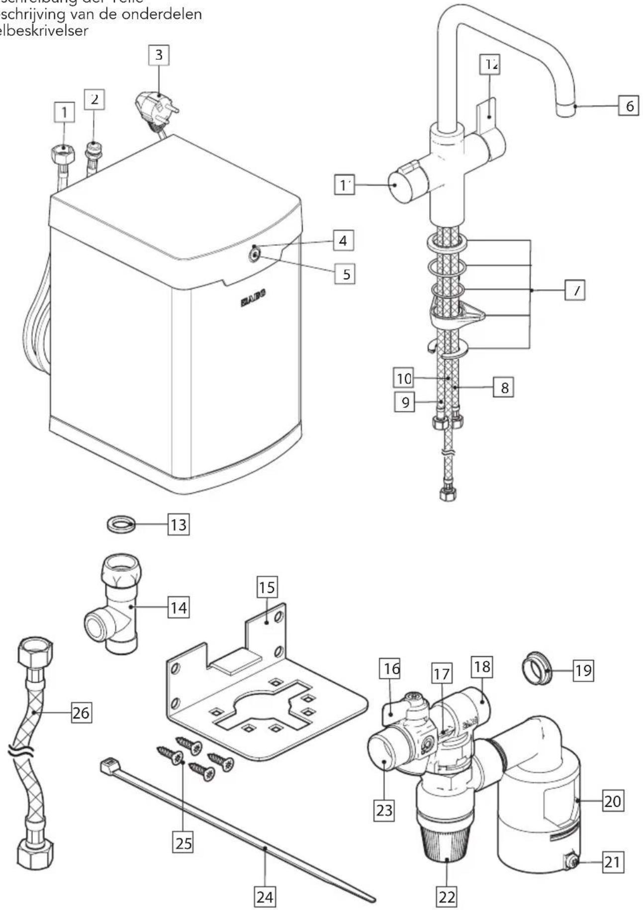
3.1 Main components appliance (see image 1)
| Part Description |
| A Boiler |
| B Tap |
| C Pressure safety valve with t-piece, hose, bracket, 4 screws and tie wrap |
| D Mixing valve with extension hose (for combi situation only) |
| E Filter with hose (optional) |
3.2 Main components boiler (see image 2)
| Part Description |
| 1 Cold water inlet (blue label) |
| 2 Boiling water outlet (red label) |
| 3 Plug |
| 4 LED indicator |
| 5 ON/OFF button |
3.3 Main components tap (see image 2)
| Part Description |
| 6 Spout |
| 7 Fastening set |
| 8 Cold water inlet (blue woven hose) |
| 9 Warm water inlet (red woven hose) |
| 10 Boiling water inlet (red label) |
| 11 Boiling water handle with safety system |
| 12 Mixer handle |
3.4 Main components pressure safety valve (see image 2)
| Part Description |
| 13 Seal |
| 14 T-piece |
| 15 Bracket |
| 16 Valve |
| 17 Flow direction indicators |
| 18 Cold water outlet |
| 19 Adapter |
| 20 Discharge connection |
| 21 Screw funnel |
| 22 Pressure-relief device |
| 23 Cold water inlet |
| 24 Tie wrap |
| 25 Screws |
| 26 Cold water hose |
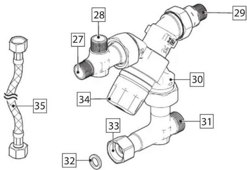
3.5 Main components mixing valve (for combi situation only; see image 2)
| Part Description |
| 27 Boiling water inlet or outlet (indicated by “H”) |
| 28 Boiling water inlet or outlet (indicated by “H”) |
| 29 Warm water outlet (indicated by “MIX”) |
| 30 Cold water inlet (indicated by “C”) |
| 31 Cold water outlet |
| 32 Seal |
| 33 Cold water inlet |
| 34 Temperature regulator |
| 35 Extension hose |
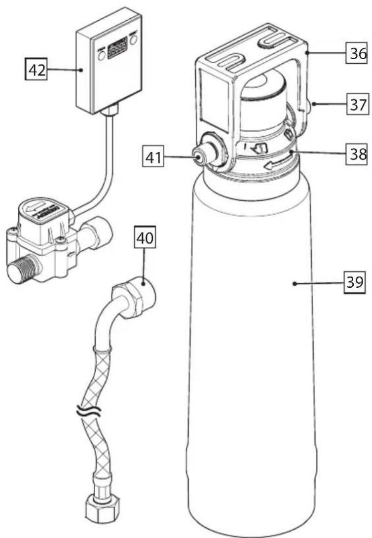
3.6 Main components filter (optional; see image 2)
| Part Description |
| 36 Bracket |
| 37 Water inlet |
| 38 Filter head |
| 39 Cartridge |
| 40 Filter hose |
| 41 Water outlet |
| 42 Flow meter |
4. INSTALLATION
4.1 Important installation information
- Read and follow all instructions in the SAFETY INFORMATION section.
- Refer to the separate manuals supplied with the other components for more relevant information.
4.2 Before installation
Step Action
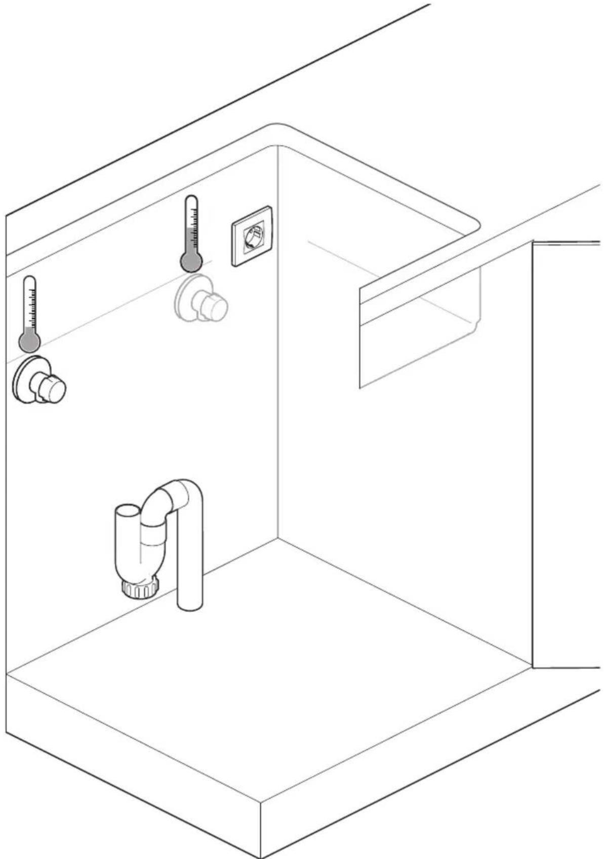
1 Make sure that you have the following installed in your kitchen cabinet (see image 3):
• Discharge pipe with siphon (∅ 40 mm) • Earthed AC wall socket (with 16A fuse) - Cold water supply (with water of drinking water quality and with a 3/8" outer thread) - Warm water supply (with a 3/8" outer thread). If not available you need to follow the instructions for the combi configuration.
2 Rinse all supplied hoses with water thoroughly
4.3 Before installation
Step Action
1 Determine which configuration you are going to install.
The appliance is available for 2 different configurations:
• Solo situation (see image 4) • Combi situation (see image 5)
The solo configuration supplies only boiling water. Warm water comes from the central boiler.
The combi configuration supplies both boiling and warm water.
2 Make sure you have all components.
If you install the solo configuration:
- Make sure you have the following components: A, B, C and E (optional). Make sure everything is complete and that no parts are missing (see image 1).
If you install the combi configuration:
- Make sure you have the following components: A, B, C, D and E (optional). Make sure everything is complete and that no parts are missing (see image 1).
| Step Action | |
| 3 Install the tap.- Install the tap (B) according to the instructions supplied with the tap (see image 6). | |
| 4 Optional: install the filter.- If you need a filter, install the filter (E) according to the instructions supplied with the filter (see image 7).- When you install the flow meter, mount the flow meter (42) to the filter according to the instructions supplied with the filter. | |
| 5 Attach the t-piece.- Attach the t-piece (14) to the cold water supply and place the seal (13) in between (see image 8). | |
| 6 Mount the pressure safety valve.If you install the solo configuration:- Attach the pressure safety valve (C) to the bracket (15) with the tie wrap (24) according to the instructions supplied with the pressure safety valve.- Place the pressure safety valve (C) with the discharge connection (20) on the siphon (see image 9).- Mount the bracket (15) with the four screws (25) to the wall of the kitchen cabinet (see image 10).If you install the combi configuration:- Mount the pressure safety valve (C) to the mixing valve (D) and place the adapter (19) and seal (32) in between (see image 11).- Attach the pressure safety valve (C) to the bracket (15) with the tie wrap (24) according to the instructions supplied with the pressure safety valve.- Place the pressure safety valve (C) with the discharge connection (20) on the siphon (see image 12).- Mount the bracket (15) with the four screws (25) to kitchen cabinet wall (see image 10). | |
| 7 Attach the discharge connection.- Attach the discharge connection (20) to the siphon using the screw funnel (21) (see image 13). | |
| 8 Connect the pressure safety valve. | |
| If you are using a filter: - Connect one end of the filter hose (40) to the t-piece (14) and the other end to the water inlet of the filter (37) (see image 14). - Connect one end of the cold water hose (26) to the water outlet of the filter (41) and the other end to the cold water inlet of the pressure safety valve (23) (see image 15). | |
| If you do not use a filter: - Connect one end of the cold water hose (26) to the t-piece (14) and the other end to the cold water inlet of the pressure safety valve (23) (see image 16). | |
| 9 Connect the boiler. | |
| If you install the solo configuration: - Connect the cold water inlet of the boiler (1) to the cold water outlet of the pressure safety valve (18) (see image 17). NOTICE! The cold water inlet of the boiler (1) bears a blue label. | |
| If you install the combi configuration: - Connect the cold water inlet of the boiler (1) to the cold water outlet of the mixing valve (31) (see image 18). NOTICE! The cold water inlet of the boiler (1) bears a blue label. | |
| 10 Connect the boiling water. | |
| If you install the solo configuration: - Connect the boiling water outlet of the boiler (2) to the boiling water inlet of the tap (10) (see image 19). NOTICE! The boiling water outlet of the boiler (2) bears a red label. The boiling water inlet of the tap (10) bears a red label. | |
| If you install the combi configuration: - Connect the boiling water outlet of the boiler (2) to one end of the extension hose (35). Connect the other end of the extension hose (35) to the boiling water inlet of the mixing valve (27 or 28) (see image 20). NOTICE! The boiling water outlet of the boiler (2) bears a red label. The boiling water inlet of the mixing valve (27 or 28) is indicated with “H”. - Connect the boiling water inlet of the tap (10) to the boiling water outlet of the mixing valve (27 or 28) (see image 21). NOTICE! The boiling water inlet of the tap (10) bears a red label. The boiling water outlet of the mixing valve (27 or 28) is indicated with “H”. | |
| 11 Connect the cold water.- Connect the cold water inlet of the tap (8) to the t-piece (14) (see image 22). NOTICE! The cold water inlet of the tap (8) is the blue woven hose. | |
| 12 Connect the warm water.If you install the solo configuration:- Connect the warm water inlet of the tap (9) to the warm water supply (see image 23). NOTICE! The warm water inlet of the tap (9) is the red woven hose.If you install the combi configuration:- Connect the warm water inlet of the tap (9) to the warm water outlet of the mixing valve (29) (see image 24). NOTICE! The warm water inlet of the tap (9) is the red woven hose. The warm water outlet of the mixing valve (29) is indicated with “MIX”. |
4.4 Filling the appliance with water

CAUTION! Do not insert the plug of the boiler into the earthed AC wall socket! First fill the system with cold water according to the instructions in this section.
To fill the appliance with cold water:
| Step Action | |
| 1 | Make sure all connections are tightened properly to prevent leakages. |
| 2 | Make sure water can drip freely from the pressure-relief device (22). |
| 3 | If the mixing valve is (D) installed, set the temperature with the temperature regulator (34). |
| 4 | Make sure the valve (16) on the pressure safety valve is in the OPEN position. |
| 5 | Open the cold water supply valve. |
| 6 | If present, open the warm water supply valve. |
| 7 | Check all connections for water tightness. |
| 8 | Push and hold the button on the boiling water handle (11). Turn the handle counterclockwise to open the valve. Keep the valve open until a constant flow of water flows out the spout. |
| 9 | Move the mixer handle (12) to the right to open the valve. Keep the valve open until a constant flow of water flows out the spout. The system is now fully filled with water. |
4.5 Starting the boiler
| Step Action |
| 1 Connect the plug of the boiler (3) to the earthed AC wall socket.CAUTION! Extension cables and multi-plug adapters are not permitted between the electrical socket and boiling water storage heater connection. |
| 2 Press the ON/OFF button (5) for min. 0.5 seconds. The white LED indicator (4) comes on when the boiler starts. Wait until the boiler is heated. For the 4 litre boiler approximately 15 minutes are necessary to heat. For the 8 litre boiler approximately 21 minutes are necessary to heat. |
| 3 Push and hold the button on the boiling water handle (11). Turn the handle counterclockwise to open the valve. Keep the valve open until the system is flushed with one boiler fill (4 or 8 litres). |
| 4 Give all user manuals to the end user of the appliance. The appliance is now fully installed and ready for daily use. |
5. DAILY USE
5.1 Important operation information
- Read and follow all instructions in the SAFETY INFORMATION section.
- Refer to the separate manuals supplied with the other components for other relevant information.
- The amount of boiling water provided is limited by the size of your boiler. When no boiling water is provided anymore, close the boiling water tap and wait until the boiler is heated. For the 4 litre boiler approximately 15 minutes are necessary to heat. For the 8 litre boiler approximately 21 minutes are necessary to heat.
5.2 Using the boiling water tap
The boiling water tap has a handle with safety function enabled with a pressure and rotation motion. The handle retracts if released and locks automatically.

WARNING! Temperature of water delivered by boiling water tap can be very hot and can cause scalding!
To open and close the boiling water tap:
| Step Action |
| 1 Push and hold the button on the boiling water handle (11). Turn the handle counterclockwise (see image 25). |
| 2 Release the button to close the boiling water tap. The handle closes automatically. |

To get the best results, for example to prepare coffee or tea, it is necessary to let the first water flow. This allows removing air bubbles that are in the water and tend to form a layer of foam on the preparation.
5.3 Using the mixed water tap

WARNING! Temperature of water delivered by mixed water tap can reach 65°C and can be hot!
To open and close the mixed water tap:
| Step Action |
| 1 Open the mixer handle (12) to the right to start water supply. The more the handle is opened the more water is supplied (see image 26). |
| 2 Move the mixer handle (12) forward to open cold water. Move the mixer handle backward to open warm water (see image 27). |
6. MAINTENANCE, CARE AND CLEANING
6.1 Important information
- Read and follow all instructions in the SAFETY INFORMATION section.
- Refer to the separate manuals supplied with the other components for other relevant maintenance, care and cleaning information.
6.2 Frequency of tasks
| Task Frequency | |
| Clean the appliance with a dry, lint-free cloth. Do not use detergents or other solvents to clean the appliance. | Monthly |
| Turn the pressure-relief device (22) clockwise to remove lime deposits and contamination. Makes sure the pressure-relief device is not blocked. | Every 6 months |
| Remove water and any lime deposits from the pressure-relief device (22) | Annually |
| Replace the filter cartridge Annually, or if the appliance is not used for 4 weeks or more. | |
7. TROUBLESHOOTING
7.1 Important troubleshooting information
- Read and follow all instructions in the SAFETY INFORMATION section.
- Refer to the separate manuals supplied with the other components for other relevant troubleshooting information.
- Refer to solutions provided in this section before you contact Customer Care and Service.

WARNING! If a solution does not result in the desired effect, disconnect the plug from the earthed AC wall socket and contact Customer Care and Service. Only qualified, certified personnel may repair the appliance. When contacting Customer Care and Service, ensure that you have the following data available:
- Model
- PNC
- Serial Number
The information can be found on the rating plate.
| Problem Cause Solution | ||
| The red LED light on the boiler flashes every 0.5 seconds. | The boiler is not filled with water and is turned on (dry-on situation). | This is a locked error and can only be reset by unplugging the power plug. |
| The red LED light on the boiler flashes every 1.0 seconds. | The sensors are disconnected and/or the thermal fuse is broken because of a faulty temperature. The heating element is turned off and the boiler is in error mode. | The appliance needs to be repaired. Contact Customer Care and Service. |
| No water from tap/steam comes out of the tap | A valve is closedA hose is bentNo water pressure | Make sure that all valves are openMake sure that hoses are not bentMake sure that the water pressure is not less than 0.15 MPaContact your water supplier if problems are not solved |
| No boiling water from tap | The boiler is turned offThe plug is disconnectedThe earth leakage protection switch is in the open position | Press the ON/OFF button (5) for min. 0.5 seconds.Connect the plug of the boiler (3) to the earthed AC wall socketMake sure the earth leakage protection switch is in closed position. |
| No warm water from tap | The boiler is turned offThe plug is disconnectedThe earth leakage protection switch is in the open positionThe temperature regulator of the mixing valve (26) is set to a low value | Press the ON/OFF button (5) for min. 0.5 secondsConnect the plug of the boiler (3) to the earthed AC wall socketMake sure the earth leakage protection switch is in closed positionIncrease the temperature with the temperature regulator (26) |
| Flow rate too low | The system contains scaling or contaminationA hose is bent | Make sure that hoses are not bentContact Customer Care and Service. |
| Problem Cause Solution | |
| Flow rate too high Too much pressure • | Close the valve of the pressure safety valve (23) or the cold water supply valve. • Place a pressure reducing valve |
| Water drips from the discharge pipe of the pressure-relief device | • Do not do anything. This is normal. |
8. TECHNICAL INFORMATION
8.1 Important other technical information
- Refer to the separate manuals supplied with the other components for other relevant technical information.
8.2 General data
| Name AEG ProSource |
| Ambient temperature 4~38 °C |
| Humidity range 25~85% relative humidity (RH) |
| Maximum operation height 2000 m |
| Protection grade IPX4 |
8.3 Electrical data
| 4 litre 8 litre | ||
| Connection Earthed AC wall socket | ||
| Voltage supply 230 V AC; 50 Hz | ||
| Max. power consumption | 2200 W | |
| Standby power loss (in ON position) | 15 W | 20 W |
| Standby power loss (in OFF position) | 0.4 W | 0.4 W |
8.4 Sanitary data
| 4 litre 8 litre | |
| Capacity boiler 4 | 8 | | |
| Minimum water supply pressure 0.15 MPa (1.5 bar) | |
| Maximum water supply pressure 0.4 Mpa (4 bar) | |
| Flow rate boiling water at 0,15 MPa (1.5 bar) flow pressure | Solo configuration: Approx. 2.4 l/minCombi configuration: Approx. 2.6 l/min |
| Flow rate boiling water at 0,4 MPa (4 bar) flow pressure | Solo configuration: Approx. 4.0 l/minCombi configuration: Approx. 3.7 l/min |
| Flow rate mixed water at 0,15 MPa (1.5 bar) flow pressure | Solo configuration: n.a.Combi configuration: Approx. 3.1 l/min |
| Flow rate mixed water at 0,4 MPa (4 bar) flow pressure | Solo configuration: n.a.Combi configuration: Approx. 5.8 l/min |
| Temperature regulation Thermostatic mixing valve | |
| Pressure safety Depends on local or national situation | |
| Heating time from 10 °C to 100 °C Approx. 15 minutes Approx. 21 minutes | |
| Max. chlorine value 100 mg/l | |
| Minimum temperature mixed water (°C) | Combi configuration: 35.8 |
| Maximum temperature mixed water (°C) | Combi configuration: 63.7 |
TABLE OF CONTENTS
- INTRODUCTION....45
- SAFETY INFORMATION....46
- PRODUCT DESCRIPTION....49
- INSTALLATION....52
- DAILY USE....56
- MAINTENANCE, CARE AND CLEANING....58
- TROUBLESHOOTING....58
- TECHNICAL INFORMATION......60
FOR PERFECT RESULTS
3. PRODUCT DESCRIPTION


- CONTENTS
- FOR PERFECT RESULTS
- VISIT OUR WEBSITE TO
- CUSTOMER CARE AND SERVICE
- INTRODUCTION
- INTENDED USE AND UNINTENDED USE
- GENERAL WORKING PRINCIPLE
- ARTICLE NUMBERS
- SAFETY INFORMATION
- CHILDREN AND VULNERABLE PEOPLE SAFETY
- INSTALLATION
- WATER CONNECTION
- ELECTRICAL CONNECTION
- PRESSURE SAFETY VALVE INSTALLATION
- FILTER INSTALLATION
- USE
- WARNING
- CARE AND CLEANING
- REPAIR, DISASSEMBLE, DISCARD
- PROCEDURE IN THE EVENT OF BREAKS IN OPERATION
- PRODUCT DESCRIPTION
- MAIN COMPONENTS APPLIANCE (SEE IMAGE 1)
- MAIN COMPONENTS BOILER (SEE IMAGE 2)
- MAIN COMPONENTS TAP (SEE IMAGE 2)
- MAIN COMPONENTS PRESSURE SAFETY VALVE (SEE IMAGE 2)
- MAIN COMPONENTS MIXING VALVE (FOR COMBI SITUATION ONLY; SEE IMAGE 2)
- MAIN COMPONENTS FILTER (OPTIONAL; SEE IMAGE 2)
- IMPORTANT INSTALLATION INFORMATION
- BEFORE INSTALLATION
- STEP ACTION
- FILLING THE APPLIANCE WITH WATER
- STARTING THE BOILER
- DAILY USE
- IMPORTANT OPERATION INFORMATION
- USING THE BOILING WATER TAP
- TO OPEN AND CLOSE THE BOILING WATER TAP
- USING THE MIXED WATER TAP
- TO OPEN AND CLOSE THE MIXED WATER TAP
- MAINTENANCE, CARE AND CLEANING
- IMPORTANT INFORMATION
- FREQUENCY OF TASKS
- TROUBLESHOOTING
- IMPORTANT TROUBLESHOOTING INFORMATION
- TECHNICAL INFORMATION
- IMPORTANT OTHER TECHNICAL INFORMATION
- GENERAL DATA
- ELECTRICAL DATA
- TABLE OF CONTENTS
Brand : AEG
Model : GYB00816ST
Category : Boiler