
DHR-1000 - VCR SONY - Free user manual and instructions
Find the device manual for free DHR-1000 SONY in PDF.


| Product Type | Video Cassette Recorder (VCR) |
| Brand | Sony |
| Model | DHR-1000 |
| Video Format | VHS |
| Dimensions (W x H x D) | Approx. 430 x 95 x 280 mm |
| Weight | Approx. 4.0 kg |
| Power Supply | 110-240 V AC, 50/60 Hz |
| Power Consumption | 20 W |
| Input/Output Terminals | RF In/Out, AV In/Out, S-Video Out, Audio Out (L/R) |
| Recording Modes | SP, LP, EP |
| Timer Recording | Yes, up to 8 programs |
| Special Features | Auto Tracking, On-Screen Display, Index Search, Hi-Fi Stereo Sound |
| Remote Control | Infrared with full function buttons |
| Safety Class | Class I (grounded) |
| Operating Temperature | 5°C to 40°C |
| Cleaning and Maintenance | Use a dry soft cloth for exterior; clean video heads with a head cleaning cassette |
| Spare Parts Availability | Contact Sony service center for belts, heads, and other parts |
| Repairability | Serviceable by authorized technicians; user-replaceable parts include remote batteries |
Frequently Asked Questions - DHR-1000 SONY
User questions about DHR-1000 SONY
0 question about this device. Answer the ones you know or ask your own.
Ask a new question about this device
Download the instructions for your VCR in PDF format for free! Find your manual DHR-1000 - SONY and take your electronic device back in hand. On this page are published all the documents necessary for the use of your device. DHR-1000 by SONY.
USER MANUAL DHR-1000 SONY
Digital Video Cassette Recorder
Operating Instructions
DV Digital Video Cassette Mini DV Digital Video Cassette
VCRplus+
DHR-1000
WARNING
To prevent fire or shock hazard, do not expose the unit to rain or moisture.


This symbol is intended to alert the user to the presence of uninsulated “dangerous voltage” within the product’s enclosure that may be of sufficient magnitude to constitute a risk of electric shock to persons.

This symbol is intended to alert the user to the presence of important operating and maintenance (servicing) instructions in the literature accompanying the appliance.
CAUTION
To prevent electric shock, do not use this polarized AC plug with an extension cord, receptacle or other outlet unless the blades can be fully inserted to prevent blade exposure.
Precautions
Safety
- Operate the unit only on 120 V AC, 60 Hz.
- If anything falls into the cabinet, unplug the unit and have it checked by qualified personnel before operating it any further.
- One blade of the plug is wider than the other for safety purposes and will fit into the power outlet only one way. If you are unable to insert the plug fully into the outlet, contact your Sony dealer.
- Unplug the unit from the wall outlet if you do not intend to use it for an extended period of time. To disconnect the cord, pull it out by the plug, never by the cord.
- Do not use the unit in areas where there is a danger of it becoming wet.
Installing
- This unit is equipped with a fan at the rear. Do not insert objects or touch the fan during operation.
- To prevent internal heat buildup, install the unit at least 5 cm away from the wall, and dust the unit periodically.
- Do not place the unit on surfaces (rugs, blankets, etc.) or near materials (curtains, draperies) that may block the ventilation slots.
- Do not install the unit near heat sources such as radiators or air ducts, or in a place subject to direct sunlight, excessive dust, mechanical vibration, or shock.
- Do not install the unit in an inclined position. It is designed to be operated in a horizontal position only.
- Keep the unit and cassettes away from equipment with strong magnets, such as microwave ovens or large loudspeakers.
- Do not place heavy objects on the unit.
- Do not place any objects containing liquid (e.g., vases) on the unit.
- If the unit is brought directly from a cold to a warm location, moisture may condense inside the VCR and cause damage to the video head and tape. When you first install the unit, or when you move it from a cold to a warm location, wait for about one hour before operating the unit.
Information
For customers in the USA
This equipment has been tested and found to comply with the limits for a Class B digital device, pursuant to Part 15 of the FCC Rules. These limits are designed to provide reasonable protection against harmful interference in a residential installation. This equipment generates, uses, and can radiate radio frequency energy and, if not installed and used in accordance with the instructions, may cause harmful interference to radio communications. However, there is no guarantee that interference will not occur in a particular installation. If this equipment does cause harmful interference to radio or television reception, which can be determined by turning the equipment off and on, the user is encouraged to try to correct the interference by one or more of the following measures:
- Reorient or relocate the receiving antenna.
- Increase the separation between the equipment and receiver.
- Connect the equipment into an outlet on a circuit different from that to which the receiver is connected.
- Consult the dealer or an experienced radio/TV technician for help.
You are cautioned that any changes or modifications not expressly approved in this manual could void your authority to operate this equipment.
Caution
Television programs, films, video tapes and other materials may be copyrighted. Unauthorized recording of such material may be contrary to the provisions of the copyright laws. Also, use of this recorder with cable television transmission may require authorization from the cable television transmission and/or program owner.
Owner's record
The model number is located at the rear and front of the unit and the serial number on the top. Record these numbers in the spaces provided below. Refer to them whenever you call upon your Sony dealer regarding this product.
Model No. ____
Serial No. ____
Table of contents
4 Features
Getting Started
8 Step 1: Unpacking
9 Step 2: Setting up the remote commander
11 Step 3: Hookups
27 Setting the clock
30 Presetting channels
33 Setting up cable box control
36 Setting up VCR Plus+
Basic Operations
38 Playing a tape
39 Recording TV programs
40 Recording TV programs using VCR Plus+
42 Setting the timer manually
Additional Operations
44 Playing/searching at various speeds
45 Displaying tape information
46 Selecting the sound
47 Recording stereo and bilingual programs
48 Recording TV programs using the quick timer
49 Searching using the index function
51 Checking/changing/cancelling timer settings
53 Adjusting the picture (Y/C delay)
54 Changing menu options
57 Erasing the cassette memory
Editing
58 Before editing
Editing with LANC cable
64 Connections
67 Copying a tape
68 Cutting out unwanted scenes
70 Assemble editing
73 Video insert editing
75 Audio insert editing
Editing without LANC cable
77 Connections
79 Copying a tape
80 Cutting out unwanted scenes
82 Video insert editing
84 Audio insert editing
Other editing features
86 Audio dubbing
88 Listening to the inserted/dubbed sound
89 Connecting a title or editing controller
91 Connecting a capture board or video printer
Additional Information
General setup information
Precautions
Troubleshooting
Specifications
Index to parts and controls
Index to MENU screens
Back cover Index
Features
Thank you for purchasing the Sony Digital Video Cassette Recorder (VCR). This Digital VCR has the following features:
High-quality digital picture and sound
Over 500 lines of horizontal resolution
This VCR achieves the highest resolution picture in home video equipment.
PCM-recorded digital sound
This VCR records sound as digital signals. There are two audio recording modes:
- 16-bit mode: for high sound quality. Sound is recorded and played back at 16-bit quantization and 48 kHz sampling frequency, the same quality as DAT (Digital Audio Tape).
- 12-bit mode: for audio dubbing. Sound is recorded and played back at 12-bit quantization and 32 kHz sampling frequency. This mode provides two stereo sound tracks.
Clear Frame Technology that enables clear still pictures
Conventional VCRs normally display still pictures by skipping every other scanning line. This VCR substitutes data for the missing lines and displays the still picture in more detail.
Advanced editing features
DV
With digital-to-digital connection, video and audio signals are transmitted in digital form for high-quality editing.
Detachable operation panel
Controls used for editing are arranged together on an operation panel. You can also detach the operation panel for convenient operation.
Edit Window
The Edit Window displays up to 10 edit points during assemble editing. This feature lets you check each editing start/end point visually.
Convenient features made possible with the DV format
Quick access with sub-code data
Index signals are written separately from video/audio signals on a sub-code data track. This enables the VCR to quickly locate a specific recording.
Recording data display
With the DV format, data such as the recording date and time are recorded onto the tape. Information such as the shutter speed, program AE mode, white balance, iris and gain are also recorded with a Sony digital camcorder. You can call up this information on the TV screen.
Cassette memory search
When you record programs on a tape with cassette memory, the programs are displayed as a list. Choose a program from the list and the VCR will locate the recording. You can also search for scenes recorded in the Photo mode with a digital camcorder.
Features (continued)
Using DV cassettes
Use D and MiniD cassettes with this VCR.
DV180 can record programs for 180 minutes and MiniDV60 can record for 60 minutes. You can use Mini DV cassettes with digital camcorders.
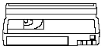
DV cassette
Mini DV cassette
You cannot use 8, Hi8, VHS, VHSC, SVHS, SVHSC, B, nor ED Beta tapes on this VCR.
Cassette memory
Cassette memory is an optional feature that is mounted on some DV cassettes and Mini DV cassettes. When you record a program, the recording date and time, and the programs' position on the tape are stored in the cassette memory so that you can quickly search for the program later on.
DV tapes with cassette memory are marked with the CMark. C114K indicates that 4 kbits of data can be stored on that cassette. This VCR can retrieve up to 16 kbits of data.
Notes
- You cannot play back a DV tape recorded in other color systems on this VCR. • DV anDV are trademarks.
To save a recording
To prevent accidental erasure of a recording, slide in the tab on the cassette so that the red portion becomes visible. To record on a tape, slide out the tab so that the red portion is hidden.

DV recording format
The following figure shows how signals are recorded on a DV tape.

Copyright precautions
On recording
You cannot record any software having copyright protection signals on this VCR. If you start recording protected video and audio signals, a warning message appears on the TV screen and the VCR stops recording.
If you timer record a program that is encoded with copyright protection signals, the VCR will continue recording but the video and audio signals will not be recorded on tape.
On playback
When you play back software having copyright protection signals on this VCR, you may not be able to copy it onto other equipment.
Getting Started Step 1: Unpacking
Check that you have the following items:
- Remote commander

- Control S cable

- LANC cable

- Size AA (R6) batteries

- S-Video cable

- Audio/video cable (3-phono to 3-phono)

- Cleaning cassette
- Cable mouse (cable box controller)


- 75-ohm coaxial cable with F-type connectors

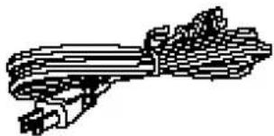
- AC power cord
Step 2: Setting up the remote commander
Notes
- With normal use, the batteries should last for approximately three to six months.
- If you will not use the remote commander for an extended period, remove the batteries to avoid possible damage from battery leakage.
- Do not use a new battery with an old one.
- Do not use different types of batteries together.

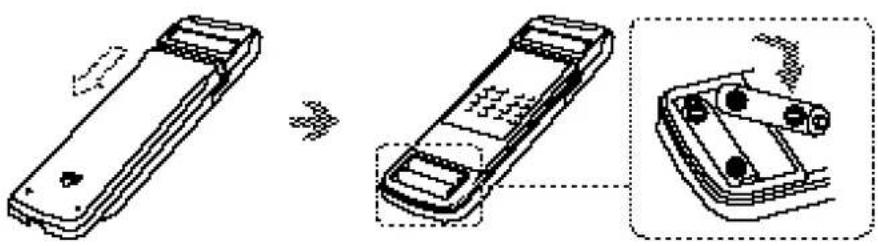
Inserting the batteries
Insert two size AA (R6) batteries by matching the + and - on the batteries with the diagram inside the battery compartment.
Setting the COMMAND MODE switch
To remotely control the VCR with the commander, set COMMAND MODE on the remote commander to the same position as that on the VCR. Usually set to VCR 4. If the other VCR does not have a COMMAND MODE switch, use the following setting:
VTR 1: For Sony Betamax format VCRs
VTR 2: For Sony 8mm format VCRs
VTR 3: For Sony VHS format VCRs
VTR 4: For Sony DV format VCRs
VTR 5 and 6: (reserve)
Using the remote commander
You can use this remote commander to operate this VCR and a Sony TV. The POWER, VOL +/-, CH +/-, TV / VTR, channel number, ENTER, DISPLAY and AUDIO MONITOR buttons on the remote commander can be used to operate your TV.
To operate Set TV / VTR to
the VCR □VTR and point at the remote sensor on the VCR
a Sony TV TV and point at the remote sensor on the TV
(continued)
Step 2: Setting up the remote commander (continued)
Notes
- If the TV uses a different remote control system from the one programmed to work with the VCR, you cannot control your TV with the remote commander.
- If you enter a new code number, the code number previously entered will be erased.
- When you replace the batteries of the remote commander, the code number automatically resets to 1 (Sony). Reset to the appropriate code number.
Controlling other TVs with the remote commander
The remote commander is preprogrammed to control non-Sony TVs. If your TV is listed in the table below, set the appropriate manufacturer's code number.
1 Set TV / VTR at the top of the remote commander to TV. 2 Hold down POWER, and enter your TV's code number(s) using the number buttons. Press the ENTER button. Then release POWER. Now you can use the POWER, VOL +/-, CH +/- and TV / VTR buttons to control your TV. To control the VCR, reset TV / VTR to VTR.
Code numbers of controllable TVs
If more than one code number is listed, try entering them one at a time until you find the one that works with your TV.
| Manufacturer Code number | |
| Sony 01 | |
| Akai 04 | |
| AOC 04 | |
| Centurion 12 | |
| Coronado 03 | |
| Curis-Mathes 12 | |
| Daytron 12 | |
| Emerson 03, 04, 14 | |
| Fisher 11 | |
| General Electric 06, 10 | |
| Goldstar 03, 04, 17 | |
| Hitachi 02, 03 | |
| J.C.Penney | 04, 12 |
| JVC | 09 |
| KMC | 03 |
| KTY | 03, 04 |
| Magnavox | 03, 08, 12 |
| Marantz | 04, 13 |
| MGA/Mitsubishi 04, 12, 13 | |
| NEC 04, 12 | |
| Manufacturer Code number | |
| Panasonic 06, 19 | |
| Philco | 03, 04 |
| Philips | 08 |
| Pioneer | 16 |
| Portland 03 | |
| Quasar 06 | |
| Radio Shack | 05, 14 |
| RCA 04, 10 | |
| Sampo | 12 |
| Samsung | 03, 12 |
| Sanyo | 11 |
| Scott 12 | |
| Sears | 07, 11 |
| Sharp | 03, 05, 18 |
| Sylvania | 08, 12 |
| Teknika | 03, 08, 14 |
| Toshiba | 07 |
| Wards | 03, 04, 12 |
| Yorx | 12 |
| Zenith | 15 |
Step 3: Hookups
Caution
- Connections between the VCR's VHF/UHF connector and the antenna terminals of the TV receiver should be made only as shown in the following instructions. Failure to do so may result in operation that violates the regulations of the Federal Communications Commission regarding the use and operation of RF devices. Never connect the output of the VCR to an antenna or make simultaneous (parallel) antenna and VCR connections at the antenna terminals of your receiver.
Note to CATV system installer
- This reminder is provided to call the CATV system installer's attention to Article 820-40 of the NEC that provides guidelines for proper grounding and, in particular, specifies that the cable ground shall be connected to the grounding system of the building, as close to the point of cable entry as practical.
* DSS ® is a registered trademarks of DIRECTV, Inc., a unit of Hughes Electronics Corporation.
Selecting the best hookup option
There are many ways in which your VCR can be hooked up. To hook up your VCR so that it works best for you, first scan through the table below. Then use the accompanying diagrams and procedures on the following pages to set up your VCR.
| If you have | Use | Refer to |
| TV that has audio/video inputs | Audio/video (A/V) hookup, then follow one of the hookups below. | Page 12 |
| Cable box that is compatible with the VCR's cable box control feature | Hookup 1 | Page 14 |
| No cable box or incompatible cable box with only a few scrambled channels | Hookup 2 | Page 16 |
| Antenna only, no cable TV | Hookup 3 | Page 18 |
| Incompatible cable box with many scrambled channels | Hookup 4 | Page 20 |
| DSS®(Digital Satellite System)* receiver | Hookup 5 | Page 22 |
| Incompatible cable box with only a few scrambled channels, using an A/B switch | Hookup 6 | Page 24 |
After you've completed the connections, follow the instructions for setup. During setup, if you need more details on the procedure described, page numbers are provided where you can find complete, step-by-step instructions.
After you've completed the setup, you're ready to use your VCR. Procedures differ depending on the hookup you used.
Before you get started
- Turn off the power to all equipment.
- Do not connect the AC power cords until all of the connections are completed.
- Be sure you make connections firmly. Loose connections may cause picture distortion.
- If your TV doesn't match any of the examples provided, see your nearest Sony dealer or qualified technician.
Audio/video (A/V) hookup
Note
- To play a tape in stereo, you must use the A/V connection.
If your TV has audio/video (A/V) input jacks, you will get a better picture and sound if you hook up your VCR using these connections. In addition, for a true “home theater” experience, you should connect the audio outputs of your VCR or TV to your stereo system. If your TV has an S-video input jack, you will enjoy an even better picture if you connect to the TV with the supplied S-video cable.
If your TV doesn't have A/V inputs, see the following pages for antenna or cable hookups.
If you're planning to use your VCR only to play back pictures and movies, you're finished setting up the VCR after you've made these connections. If you want to record off-air or off your cable TV system, complete these connections first, and then go to the following pages for antenna or cable hookups.
A Use this hookup if your TV has stereo jacks![graph LR A["VCR"] --> B["LINE OUT"] B --> C["Audio/video cable (supplied)"] C --> D["S-video cable (supplied)"] D --> E["TV"] E --> F["IN"] F --> G["Audio OUT"] G --> H["Stereo receiver"] H --> I["AUX IN"] I --> J["Audio cable (not supplied)"] J --> K["Audio/video cable (supplied)"] K --> L["Audio/v…](/content/2026/06/1301747/images/1e2798fa4a006176e4b662d8c33fb3813c1f690c8f213266856f9fed7dabf4cc.jpg)
B Use this hookup if your TV doesn't have stereo jacks.![graph TD A["VCR"] --> B["LINE OUT"] B --> C["VIDEO"] C --> D["S-video cable (supplied)"] D --> E["TV"] E --> F["IN"] F --> G["VIDEO"] G --> H["VIDEO"] H --> I["Audio cable (not supplied)"] I --> J["Stereo receiver"] J --> K["AUX IN"]](/content/2026/06/1301747/images/17d8177abc0cd3f134cfd210438cd0cb7cd537afa0e7ea1d31d33396b446bc62.jpg)
C Use this hookup if your TV has S-Link™ function.
If your TV has the S-Link™ (A/V bus control) function, hook up your VCR using the connection shown below. Your TV will automatically switch to the A/V inputs for your VCR when you play back or operate the menu on the VCR.
![graph LR A["VCR"] --> B["Line-1N"] A --> C["Line-CUT"] B --> D["Audio/video cable (supplied)"] C --> D D --> E["Control S cable (supplied)"] E --> F["TV"] F --> G["Audio OUT"] G --> H["Stereo receiver"] H --> I["Audio cable (not supplied)"] I --> J["AURIN"]](/content/2026/06/1301747/images/005cd6d5b69ce1c9a03669a5cc97f4989c558eb992fdf3de298e35e6c9207e1d.jpg)
A/V hookup: VCR setup
After you've connected your TV and completed antenna or cable hookup, use the following procedure to set up the VCR.
Press MENU and select ADVANCED OPTIONS.

For details, see page 54.

Set AUTO ANT SEL to OFF and press EXECUTE.
Hookup 1
Using cable box control
Recommended use
You should use this hookup if you have a cable box, especially if your cable system scrambles all or most channels. This hookup allows the VCR's cable box control feature to control the channel on the cable box, simplifying the recording process. A list of compatible cable boxes is on page 34.
What you can do with this hookup
- Record any channel using the VCR's cable box control feature to select channels on the cable box.
What you can't do with this hookup
- Record with the cable box turned off
- Record one channel while watching another channel
![graph TD A["Wall"] --> B["Cable box"] B --> C["Cable Mouse"] C --> D["VCR"] D --> E["Positioning the Cable Mouse"] E --> F["Rear of TV"] F --> G["VHF/UHF A"] G --> H["Match the type of connector on your TV: A, B, or C."] F --> I["VHF B"] I --> J["For connector types B and C, no UHF connection is req…](/content/2026/06/1301747/images/240aa4940675a7829aa36c956754bb667157c122f2d936276c71c12caa858ed7.jpg)
Hookup 1: VCR setup
1. Set the RF UNIT switch to CH 3 or CH 4, whichever channel is not used in your area. If both are used, set the switch to either channel. If you made A/V connections (from page 12), you can skip this step.
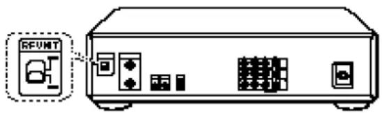
For details, see page 92.
2. Turn on your cable box. 3. Press EASY SET UP on the VCR. The SET UP menu appears.
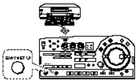
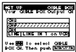
1. The CLOCK SET menu appears. Select AUTO and press EXECUTE. For details, see page 27. 2. The CABLE BOX menu appears. Set CABLE BOX CONTROL to ON and press EXECUTE. For details, see page 33. 3. Enter your cable box code number and press EXECUTE. For details, see page 33. 4. Select your cable box output channel and press EXECUTE. For details, see page 33.
Normal display ←
![NET UP C:\WINDOWS\NET U++=1 to ++1+0 Then push [M-XX-0] Push [M-XXX-0] to quill](/content/2026/06/1301747/images/f1df500f49f4a0cb7666b4f0ce3ba084b1e2edf604737111a05325335784bb90.jpg)
![MCT UP COLD PCC ORLE FOR CONTROL CHIKING U++=1 to ++1+0 Then push [M2-Xu-1] Push [HITISL +0 1] to quill](/content/2026/06/1301747/images/045886cb726105c50ab1b12003bb4fc3592f38e1054f7bcb80c2ac0afca939d8.jpg)


Hookup 1: VCR Plus+ channel setup
1. Find the VCR Plus+ Channel Listing in your program guide. For details on the VCR Plus+ Channel Listing, see page 36. 2. If the channels in the program guide are different from the channels that you actually use on your TV, set the channels that are different as follows:
Press MENU and select SET VCR Plus+ CHANNELS. Enter the program guide channel, then the channel you use on your TV.
For details, see page 37. Press EXECUTE.
Automatic clock setting
Once you've set up the VCR, it automatically sets the clock the first time you turn off the VCR. After that, whenever you turn off the VCR, it checks the time and adjusts the clock, even for Daylight Saving Time. The VCR sets the clock by picking up a time signal that's provided by some TV channels.
If you want to use the timer to record right away, or if the channels in your area do not carry time signals, set the clock manually. For details, see pages 27–29.
Note
- To use the automatic clock setting feature, leave the cable box on.
- Depending on your area, the automatic clock setting feature may not set the clock correctly. In this case, set the clock manually according to the procedure on page 29.
Hookup 2
No cable box or Incompatible cable box with only a few scrambled channels
Recommended use
Use this hookup if you do not have a cable box. Also use this hookup if your cable company cannot supply a cable box that is compatible with the VCR's cable box control feature, and your cable system scrambles only a few channels.
What you can do with this hookup
- Record any unscrambled channel by selecting the channel on the VCR
What you can't do with this hookup
- Record scrambled channels that require a cable box
![graph TD A["Wall"] --> B["VCR"] B --> C["Cable box"] C --> D["Rear of TV"] D --> E["A"] D --> F["B"] D --> G["C"] style A fill:#f9f,stroke:#333 style B fill:#ccf,stroke:#333 style C fill:#cfc,stroke:#333 style D fill:#fcc,stroke:#333 note1["Connect this cable directly to your TV if you don't have a…](/content/2026/06/1301747/images/e97b6cfd582997db019826566ffd8e5fde6800c5fd4df6a661e8477a94f4920a.jpg)
Hookup 2: VCR setup
1 Set the RF UNIT switch to CH 3 or CH 4, whichever channel is not used in your area. If both are used, set the switch to either channel. If you made A/V connections (from page 12), you can skip this step.

For details, see page 92.
2 Press EASY SET UP on the VCR. The SET UP menu appears.

1 The CLOCK SET menu appears. Select AUTO and press EXECUTE. For details, see page 27.
![SET UP CLOCK SET OK DOWN! 10:00 U++=1 to ++1+0 Then push [M-X] 0 Push [M-T] X L 0 1 to quill](/content/2026/06/1301747/images/2e2d0b372124444ecd2a2941bacea81db416084cc9c522979c15c45ca5d08c11.jpg)
2 The CABLE BOX menu appears. Set CABLE BOX CONTROL to OFF and press EXECUTE. For details, see page 33.

3 The TUNER PRESET menu appears. Set ANTENNA/CABLE to CABLE and press EXECUTE. For details, see page 30.
![SET UP TUNER PROGET 3016-2000 RST 1000 Use: 1.0 +1+1 Then push [0.0001s] Push 3.0 4.0 5.0 1.0 quil](/content/2026/06/1301747/images/f8e425e9ed8fef15395123d234089c3754eae608ce30f2fe25d1aed6e83cd1a2.jpg)
4 The AUTO PRESET starts. For details, see page 30.

Normal display ←

Hookup 2: VCR Plus+ channel setup
1 Find the VCR Plus+ Channel Listing in your program guide. For details on the VCR Plus+ Channel Listing, see page 36. 2 If the channels in the program guide are different from the channels that you actually use on your TV, set the channels that are different as follows:
Press MENU and select SET VCR Plus+ CHANNELS.
Enter the program guide channel, then the channel you use on your TV.


Press EXECUTE. For details, see page 36.
Automatic clock setting
Once you've set up the VCR, it automatically sets the clock the first time you turn off the VCR. After that, whenever you turn off the VCR, it checks the time and adjusts the clock, even for Daylight Saving Time. The VCR sets the clock by picking up a time signal that's provided by some TV channels.
If you want to use the timer to record right away, or if the channels in your area do not carry time signals, set the clock manually. For details, see pages 27–29.
Note
- To use the automatic clock setting feature, leave the cable box on.
- Depending on your area, the automatic clock setting feature may not set the clock correctly. In this case, set the clock manually according to the procedure on page 29.
Hookup 3
Antenna hookup
Make the following connections if you're using an antenna (if you don't have cable TV).
A Use this hookup if you're using:
- VHF/UHF antenna (you get channels 2–13 and channels 14 and higher)
- UHF-only antenna (you get channels 14 and higher) • separate VHF and UHF antennas
![graph TD A["VCR"] --> B["IN CUT"] B --> C["Ground"] D["Rear of TV"] --> E["A"] D --> F["B"] D --> G["C"] E --> H["VHF/UHF"] F --> I["VHF"] G --> J["UHF"] style A fill:#f9f,stroke:#333 style D fill:#ccf,stroke:#333 style E fill:#cfc,stroke:#333 style F fill:#cfc,stroke:#333 style G fill:#cfc,stroke:#…](/content/2026/06/1301747/images/0a53bd4a1853274c4c663a1b68083de03e1361811cd4c4eb0c49b561c7085681.jpg)
B Use this hookup if you're using a VHF-only antenna (you get channels 2–13 only)
If you cannot connect your antenna cable to the VCR directly
If your antenna cable is a flat cable (300-ohm twin lead cable), attach an external antenna connector (not supplied) so that you can connect the cable to the VHF/UHF IN connector. If you have separate cables for VHF and UHF antennas, you may use a U/V band mixer (not supplied). For details, see page 92.
Hookup 3: VCR setup
1 Set the RF UNIT switch to CH 3 or CH 4, whichever channel is not used in your area. If both are used, set the switch to either channel. If you made A/V connections (from page 12), you can skip this step.

For details, see page 92.
2 Press EASY SET UP on the VCR. The SET UP menu appears.

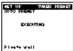
1 The CLOCK SET menu appears. Select AUTO and press EXECUTE. For details, see page 27. 2 The CABLE BOX menu appears. Set CABLE BOX CONTROL to OFF and press EXECUTE. For details, see page 33. 3 The TUNER PRESET menu appears. Set ANTENNA/CABLE to ANT and press EXECUTE. For details, see page 30. 4 The AUTO PRESET starts. For details, see page 30.
Normal display ←

![OKT UP COLD BOX COLD BOX CONTROL OK T (4:0) U+1: 1 to ++1+d Then push [OK-2001] Push ⬊[1]→[2]→[3]→[4]→[5]→[6]→[7]→[8]→[9]→[10]→[11]→[12]→[13]→[14]→[15]→[16]→[17]→[18]→[19]→[20]](/content/2026/06/1301747/images/7914f4c9be8369e1e615a2fad528aa767800e48d049c2fe0e67a970e1bb59d27.jpg)


Hookup 3: VCR Plus+ channel setup
1 Find the VCR Plus+ Channel Listing in your program guide. For details on the VCR Plus+ Channel Listing, see page 36. 2 If the channels in the program guide are different from the channels that you actually use on your TV, set the channels that are different as follows:
Press MENU and select SET VCR Plus+ CHANNELS.
For details, see page 37. Enter the program guide channel, then the channel you use on your TV.
Press EXECUTE.
Automatic clock setting
Once you've set up the VCR, it automatically sets the clock the first time you turn off the VCR. After that, whenever you turn off the VCR, it checks the time and adjusts the clock, even for Daylight Saving Time.
The VCR sets the clock by picking up a time signal that's provided by some TV channels.
If you want to use the timer to record right away, or if the channels in your area do not carry time signals, set the clock manually. For details, see pages 27–29.
Note
- To use the automatic clock setting feature, leave the cable box on.
- Depending on your area, the automatic clock setting feature may not set the clock correctly. In this case, set the clock manually according to the procedure on page 29.
Hookup 4
Incompatible cable box with many scrambled channels
Recommended use
Use this hookup if your cable company cannot supply a cable box that is compatible with the VCR's cable box control feature, and your cable system scrambles all, or most channels.
What you can do with this hookup
- Record any channel by selecting the channel on the cable box
What you can't do with this hookup
- Record with the cable box turned off
- Record one channel while watching another channel
- Record by selecting channels directly with the VCR
![graph TD A["Wall"] --> B["Cable box"] B --> C["VCR"] C --> D["Rear of TV"] D --> E["A Match the type of connector on your TV: A, B, or C."] D --> F["B For connector types B and C, no UHF connection is required."] D --> G["C UHF"]](/content/2026/06/1301747/images/fea8504d50bd28cd2190aa4ef6dd270e58e956ef2516fde7e5483b4c78768521.jpg)
Hookup 4: VCR setup
1 Set the RF UNIT switch to CH 3 or CH 4, whichever channel is not used in your area. If both are used, set the switch to either channel. If you made A/V connections (from page 12), you can skip this step.

For details, see page 92.
2 Turn on your cable box. 3 Press EASY SET UP on the VCR. The SET UP menu appears.

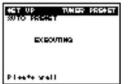
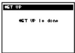
1 The CLOCK SET menu appears. Select MANUAL and press EXECUTE. For details, see page 27. 2 The CABLE BOX menu appears. Set CABLE BOX CONTROL to OFF and press EXECUTE. For details, see page 33. 3 The TUNER PRESET menu appears. Set ANTENNA/CABLE to ANT and press EXECUTE. For details, see page 30. 4 The AUTO PRESET starts. For details, see page 30.
Normal display ←
![SET UP R:100 19.56 U++=3 10 ++1+cl Then push [M-X]- Push INITIAL 50 10 quil](/content/2026/06/1301747/images/0971bb81a28f8f045b4eec40511e066e263cac7c1d3a2bffe012e04813849ddf.jpg)
![NET UP COLD POX COLD POX CONTROL OK (OK) U++=1 to ++1+0 Then push [M-X]- Push [M]#1XL Net 1 to quil](/content/2026/06/1301747/images/dd0d054d7d96d25014eb8842852c76789a3356bc15fa59cd3aa08229b20c0cf1.jpg)
![NET UP TUMOR PROSET RIMERS/CIRCLE value=0.0014 U++=3 10 ++1+0 Then push [0x200] Push COPY SET UP 10 quill](/content/2026/06/1301747/images/014fe7188b2f70fac75874222b3669b09d93d50895442dc1b60fcd61f660195e.jpg)
Hookup 4: VCR Plus+ channel setup
1 Find the VCR Plus+ Channel Listing in your program guide. For details on the VCR Plus+ Channel Listing, see page 36. 2 Enter all the channels you want to record and the cable box output channel (usually 2, 3, or 4):
Press MENU and select SET VCR Plus+ CHANNELS.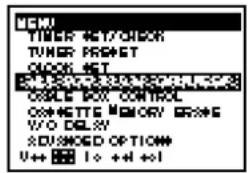
Enter the program guide channel, then the cable box output channel.
Press EXECUTE. For details, see page
Note
- You have to set the channel manually on the cable box for each recording.
Automatic clock setting
To use the Auto Clock Set feature with this hookup, you need to manually select a channel that carries a time signal:
1 Tune the cable box to a channel that carries a time signal. 2 Select AUTO in the CLOCK SET menu to turn on the Auto Clock Set feature. 3 Turn off the VCR. It automatically sets the clock and adjusts for Daylight Saving Time by picking up the time signal.
If you want to use the timer to record right away, or if the channels in your area do not carry time signals, set the clock manually. For details, see pages 27 - 29.
Note
- To use the automatic clock setting feature, leave the cable box on.
- Depending on your area, the automatic clock setting feature may not set the clock correctly. In this case, set the clock manually according to the procedure on page 29.
Hookup 5
DSS (Digital Satellite System) receiver
Recommended use
Use this hookup if you have a DSS receiver. It allows the VCR's cable box control feature to control the channel on the DSS receiver, simplifying the recording process. You should use this hookup if you have a DSS receiver. A list of compatible DSS receivers is on page 34.
DSS (Digital Satellite System) is a satellite broadcast that provides superior digital-quality video and crisp digital-quality audio. A variety of program packages are available through your program providers. It also has program guides that are sorted by program categories.
What you can do with this hookup
- Record any channel using the VCR's cable box control feature to select channels on the DSS receiver
What you can't do with this hookup
- Record any channel from cable or an antenna (To record channels from cable or an antenna, turn off the cable box control feature.)
- Use a cable box • Record programs with VCR Plus+
![graph TD A["Wall"] --> B["or"] B --> C["VCR"] C --> D["AUDIO VIDEO"] D --> E["Audio VIDEO"] E --> F["DSS receiver"] F --> G["Cable Mouse"] G --> H["VHF/UHF"] H --> I["Rear of TV"] I --> J["A Match the type of connector on your TV: A, B or C"] I --> K["B For connector types B and C, no UHF connection…](/content/2026/06/1301747/images/cdaa0abb2777832ae4a7c33e2eb553fbb25b9ac4f8317b264654fccf4b91d163.jpg)
Hookup 5: VCR setup
1 Set the RF UNIT switch to CH 3 or CH 4, whichever channel is not used in your area. If both are used, set the switch to either channel. If you made A/V connections (from page 12), you can skip this step.
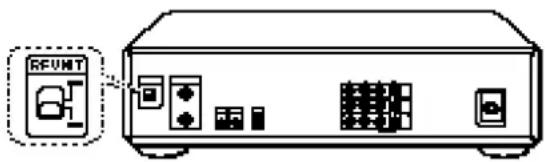
For details, see page 92.
2 Turn on your DSS receiver. 3 Press EASY SET UP on the VCR. The SET UP menu appears.

1 The CLOCK SET menu appears. Select AUTO and press EXECUTE. For details, see page 27.
![NET UP C:\WINDOWS\100\US U++=3 10 ++1+cl Then push [M-X]X-1 Push [M111X 95] 10 quill](/content/2026/06/1301747/images/f001c29dfb27b2b75b9a63c651944dc879f44a2f8b5a11e3be87531ae32f0f2b.jpg)
2 The CABLE BOX menu appears. Set CABLE BOX CONTROL to ON and press EXECUTE. For details, see page 33.
![NET UP COLD POX COLD POX CONTROL ORDER: U++=1 to ++1+0 Then push [M-X]- Push [NITIXL W] 10 quill](/content/2026/06/1301747/images/ad649e888dbdc500eb69fd236ebb11e9d1da597591fefc3800b5aa18b58b679d.jpg)
3 Enter your DSS receiver code number and press EXECUTE. For details, see page 33.

4 Select LINE (LINE IN 1 on VCR) and press EXECUTE. For details, see page 33.

5 The AUTO PRESET starts. For details, see page 33. Normal display ←

Automatic clock setting
If you connect an antenna or cable to the VCR, the Auto Clock Set feature will function. It automatically sets the clock and adjusts for Daylight Saving Time the first time you turn off the VCR.
The VCR sets the clock by picking up a time signal provided by some TV channels.
If you want to use the timer to record right away, or if the channels in your area do not carry time signals, set the clock manually. For details, see pages 27–29.
Note
- To use the automatic clock setting feature, leave the DSS receiver on.
- Depending on your area, the automatic clock setting feature may not set the clock correctly. In this case, set the clock manually according to the procedure on page 29.
You are now ready to use your VCR
Procedures differ slightly depending on the hookup used. Make a note of which hookup you used (Hookup 5) so that you can always follow the correct instructions.
Notes
- To successfully record a program from the DSS receiver, proceed as follows:
- Leave the DSS receiver on all the time.
- Turn off the display (menu screen, channel number, etc.) of the DSS receiver.
- To record or receive locked channels, unlock the channel before the VCR starts recording.
- To set pay-per-view programs in the timer setting, order the pay-per-view program before the VCR starts recording.
- Some programs are copy protected. You cannot record these programs.
Hookup 6
Incompatible cable box with only a few scrambled channels, using an A/B switch
Recommended use
By using an A/B switch (not supplied), this hookup allows you to record both scrambled and unscrambled channels conveniently.
What you can do with this hookup
- Record any unscrambled channel by selecting the channel directly on the VCR (the A/B switch is set to A)
- Record any scrambled channel by selecting the channel on the cable box (the A/B switch is set to B)
What you can't do with this hookup
- Record one scrambled channel while watching another channel
![graph TD A["Wall"] --> B["Splitter"] B --> C["Cable box"] C --> D["VCR"] D --> E["Rear of TV"] E --> F["A"] E --> G["B"] E --> H["C"] style A fill:#f9f,stroke:#333 style B fill:#ccf,stroke:#333 style C fill:#cfc,stroke:#333 style D fill:#fcc,stroke:#333 style E fill:#cff,stroke:#333 style F fill:#ff…](/content/2026/06/1301747/images/391535281b654bbd6db587693062dcc4ff241c1cb7bed888bceb1112b96ad831.jpg)
Hookup 6: VCR setup
1 Set the RF UNIT switch to CH 3 or CH 4, whichever channel is not used in your area. If both are used, set the switch to either channel. If you made A/V connections (from page 12), you can skip this step.

For details, see page 92.
2 Set the A/B switch to "A." 3 Press EASY SET UP on the VCR. The SET UP menu appears.

1 The CLOCK SET menu appears. Select AUTO and press EXECUTE. For details, see page 27.
![NET UP C:\WINDOWS\DATA\SYSTEM\V++ U++=1 10 ++1+0 Then push [M-2-X]- Push [M-1-X] 10 quill](/content/2026/06/1301747/images/6170afc3464959a496c9e44dff55ebeaae36de9006d16f9069d4e8dc3634a612.jpg)
2 The CABLE BOX menu appears. Set CABLE BOX CONTROL to OFF and press EXECUTE. For details, see page 33.
![NET UP COLD POX CONTROL OK FOR U++=1 to ++1+0 Then push [M2-Xu-1] Push ⌊HITI3.4n 1 to quil](/content/2026/06/1301747/images/b35f879498b2bc23a07c83eb8bc86548b67a8ee5db5a8d42520cc45a7de0f97e.jpg)
3 The TUNER PRESET menu appears. Set ANTENNA/CABLE to CABLE and press EXECUTE. For details, see page 30.
![4ST UP TUNER PROGET START/0015 START 0015 U++ 1.0 ++1+1 Then push [0.0015] Push 3.0 4.0 5.0 6.0 7.0 8.0 9.0 10.0 11.0](/content/2026/06/1301747/images/38f282c66e5d6f02cee37b35c45b485addf8e4af7d380021cd33a6f6f02a9acb.jpg)
4 The AUTO PRESET starts. For details, see page 30.

Normal display ←

4 Preset the cable box output channel (usually 2, 3 or 4).
Press MENU and select TUNER PRESET.
Set MANUAL SET to ADD and press EXECUTE.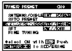
For details, see page 31.
Hookup 6: VCR Plus+ channel setup
1 Find the VCR Plus+ Channel Listing in your program guide. For details on the VCR Plus+ Channel listing, see page 36. 2 For unscrambled channels, if the channels in the program guide are different from the channels that you actually use on your TV, set the channels that are different as follows:
Press MENU and select SET VCR Plus+ CHANNELS.
Enter the program guide channel, then the channel you use on your TV.
Press EXECUTE. For details, see page
3 For scrambled channels, enter all the scrambled channels you want to record and the cable box output channel (usually 2, 3, or 4):
Press MENU and select SET VCR Plus+ CHANNELS.
Enter the program guide channel, then the cable box output channel.
For details, see page 37. Press EXECUTE.
(continued)
Getting Started
Hookup 6 (continued)
You are now ready to use your VCR
To record an unscrambled channel
1 Set the A/B switch to "A."
2 Select channels on the VCR.
To record a scrambled channel
1 Set the A/B switch to "B."
2 Select channels on the cable box (for details on the cable box, see page 33).
To watch TV
1 Turn off your VCR, or press the VCR's TV/VTR button until the VTR indicator in the display window goes off. 2 Set the A/B switch to "B." 3 Turn on your cable box. 4 Set the TV to the cable box output channel (usually 2, 3, or 4). 5 Set the cable box to the channel you want to watch.
Setting the clock

Notes
- The clock cannot be set automatically if the VCR cannot receive a channel that carries a time signal in your area. If so, set the clock manually (page 29).
- If there are only a few channels in your area that carry time signals, setting the clock automatically may take up to about 30 minutes. If nothing happens even after you wait about 30 minutes, set the clock manually (page 29).
- If you use Hookup 1 or 4, make sure you leave the cable box on.
Using the Auto Clock Set feature
Some TV and cable channels transmit time signals with their broadcasts. Your VCR can pick up this time signal to automatically set the clock. The Auto Clock Set feature works only if a channel in your area is broadcasting a time signal. If broadcasters in your area are not yet sending time signals, set the time manually (page 29).
Before you start...
- Turn on the VCR and the TV.
- Set the TV to the VCR channel (channel 3 or 4). If your TV is connected to the VCR using A/V connections, set the TV to video input.
- Press TV/VTR to display the VTR indicator in the VCR's display window.
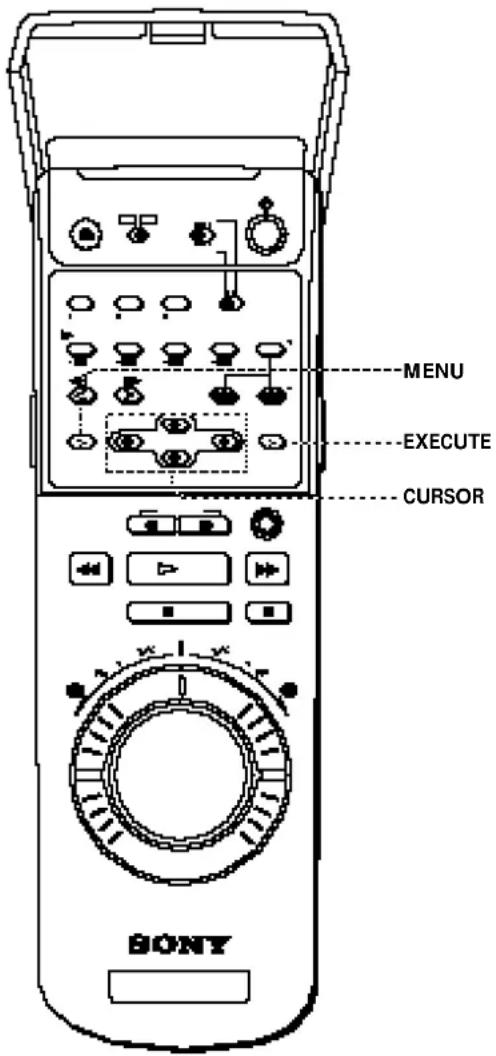
1 Press MENU, then press the CURSOR (↑/↓) buttons to move the cursor (I) to CLOCK SET and press EXECUTE. When using the EASY SET UP procedure, skip this step.

2 Press the CURSOR (←/→) buttons to select AUTO, then press EXECUTE.
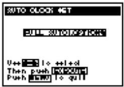
The AUTO CLOCK SET menu appears on the TV screen.

3 Press the CURSOR (←/→) buttons to select FULL AUTO, then press EXECUTE.
![AUTO LOCK GET E:\WINDOWS\DATA\1000\. U++ = 3:10 +1+0 Then push [0-200] Push = 5.001 to quit](/content/2026/06/1301747/images/4e2ca1e171d0f27acffc954faeda244b20e5e674303db1a3091e6e5adf0c8f0d.jpg)
4 To activate the Auto Clock Set function, turn the VCR off.
The VCR automatically sets the clock. The VCR automatically searches for a channel that carries a time signal and sets your time zone and daylight saving time (if applicable). If your clock is set, but displays the wrong time zone or daylight saving time, you can adjust these settings without turning off the Auto Clock Set feature (page 28).
When the Auto Clock Set feature does not work well
Depending on your area, the automatic clock setting feature may not set the clock correctly. In this case, set the clock manually according to the procedure on page 29.
(continued)
Setting the clock (continued)
Note
- If you use both the cable box control feature and the Auto Clock Set feature, the VCR automatically changes channels on the cable box until a channel that carries a time signal is found whenever you turn off the VCR. If you want to stop the search, change the channel of the cable box with the channel buttons either on the VCR or on the remote commander.
If the clock is not activated
1 Follow steps 1 and 2 in "Using the Auto Clock Set feature."
2 Press the CURSOR (←/→) buttons to select OPTIONS in the AUTO CLOCK SET menu, then press EXECUTE.
The CLOCK SET CHANNEL menu appears.
3 Press the CURSOR (←/→) buttons to select AUTO or MANUAL.
- If you select AUTO: The VCR automatically searches for a channel that carries a time signal. - If you select MANUAL: Set a channel that carries a time signal using the number buttons. Use this option if you know that channel. Most PBS member stations broadcast a time signal. For the fastest response, set the VCR to your local PBS station.
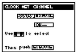

4 Press EXECUTE.
The YOUR TIME ZONE AND DAYLIGHT SAVING TIME menu appears.
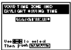
5 Press the CURSOR (←/→) buttons to select AUTO or MANUAL.
- If you select AUTO: The VCR automatically sets your time zone and daylight saving time (if applicable). - If you select MANUAL: 1 Press EXECUTE, then set the time zone of your area using the CURSOR (↑/↓) buttons. 2 Press EXECUTE, then select STANDARD TIME or DAYLIGHT SAVING TIME using the CURSOR (↑/↓) buttons.


6 Press EXECUTE.
7 To activate the Auto Clock Set function, turn the VCR off.

Using the Manual Clock Set
1 Press MENU.
The main MENU appears on the TV screen.
2 Press the CURSOR (↑/↓) buttons
to move the cursor (■) to CLOCK SET, then press EXECUTE.

3 Press the CURSOR (←/→) buttons
to select MANUAL, then press EXECUTE.

4 Set the month using the CURSOR
(↑/↓) buttons.

5 Press CURSOR → to highlight the
day and set the day using the CURSOR (↑/↓) buttons.

The day of the week is set automatically.
6 Press CURSOR → to highlight the
year and set the year using the CURSOR (↑/↓) buttons.

7 Press CURSOR → to highlight the
hour and set the hour using the CURSOR (↑/↓) buttons.

8 Press CURSOR → to highlight the
minutes and set the minutes using the CURSOR (↑/↓) buttons.

9 Press EXECUTE to start the clock.
Presetting channels
Skip this section if you are using cable box / DSS receiver control.

Tip
- When receiving a VHF, UHF or CATV channel, the display changes as follows each time you press the DISPLAY button.
Channel number, program name, and station's call letters (if the broadcaster sends those services)
↓ Date, time, remaining tape length, and time counter
This VCR is capable of receiving VHF channels 2 to 13, UHF channels 14 to 69 and unscrambled CATV channels 1 to 125. First, we recommend that you preset the receivable channels in your area using automatic presetting. Then, if there are any unwanted channels, disable them manually. If you have decided which channels you wish to preset, set them directly using manual presetting.
Before you start...
- Turn on the VCR and the TV.
- Set the TV to the video channel (channel 3 or 4). If your TV is connected to the VCR using A/V connections, set the TV to video input.
- Press TV/VTR to display the VTR indicator in the VCR's display window.
- Press INPUT SELECT so that a channel number appears in the VCR's display window.
Presetting all receivable channels automatically
1 Press MENU, then press the CURSOR (↑/↓) buttons to move the cursor (I) to TUNER PRESET and press EXECUTE.
When using the EASY SET UP procedure, skip this step.

2 Press the CURSOR (↑/↓) buttons to move the cursor (■) to ANTENNA/CABLE.

3 Select ANT or CABLE using the CURSOR (←/→) buttons:
- To preset cable TV channels, select CABLE.
- To preset VHF and UHF channels, select ANT.

4 Press the CURSOR (↑/↓) buttons to move the cursor (■) to AUTO PRESET, then press EXECUTE.
All receivable channels are preset in numerical sequence. When no more receivable channels can be found, presetting stops and the picture from the lowest numbered channel is displayed on the TV screen.


Presetting/deleting channels manually
1 Display the TUNER PRESET menu.
For instructions, follow steps 1 and 2 in "Presetting all receivable channels automatically."

2 Select the channel to preset or delete:
- To preset a channel, enter the channel number by pressing the number buttons then ENTER.
- To delete a channel, select the channel number by pressing CH +/-
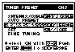
3 Set MANUAL SET to ADD or ERASE, using the CURSOR (←/→) buttons:
- To preset a channel, select ADD.
- To delete a channel, select ERASE.
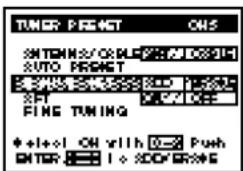
4 Repeat steps 2 and 3 to preset or delete channels as required, then press EXECUTE.
Presetting channels (continued)

If the picture is not clear
Normally, the Auto Fine Tuning (AFT) function automatically tunes in channels clearly. If, however, the picture of a channel is not clear, you may also use the manual tuning function.
1. Display the TUNER PRESET menu. For instructions, follow steps 1 and 2 in "Presetting all receivable channels automatically" on page 30.

2. Select the channel you want to fine-tune by pressing the number buttons and then ENTER.


3. Press the CURSOR (↑/↓) buttons to move the cursor (■) to FINE TUNING. The fine tuning meter appears.
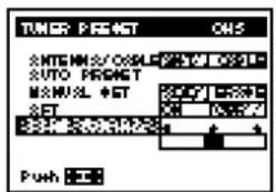
4. Press the CURSOR (←/→) buttons to get a clearer picture, then press EXECUTE. Note that the AFT setting switches to OFF.

Setting up cable box control
(Skip this section if you are using Hookup 2, 3, or 4)


Your VCR includes a cable box control feature which allows the VCR to control most brands of cable boxes/DSS receivers via the Cable Mouse. With cable box control, the VCR controls channels on the cable box/DSS receivers for timer recording. You can also use the VCR's remote commander to change channels on the cable box/DSS receiver whenever the cable box/DSS receiver is turned on even if the VCR is turned off. To use cable box control, you need to connect the Cable Mouse (page 14) and set the code number and output channel. This VCR is programmed with codes necessary to control channel selection on most brands of cable boxes at the time this VCR was manufactured. It is possible that new cable boxes may be introduced that cannot be controlled with this VCR's Cable Mouse. If you have a cable box that is incompatible with this VCR, contact your cable operator — they may be able to provide you with a compatible cable box.
Before you start...
- Turn on your TV and set it to the video channel.
- Turn on your cable box/DSS receiver.
- Press POWER to turn on the VCR.
1. Press MENU, then press the CURSOR (↑/↓) buttons to move the cursor (I) to CABLE BOX CONTROL and press EXECUTE. When using the EASY SET UP procedure, skip this step.

2 Press the CURSOR (←/→) buttons to select ON, then press EXECUTE.
3 Enter the cable box/DSS receiver code number by pressing the number buttons, then press EXECUTE. Find your cable box/DSS receiver code number from the chart on the next page.

4 • If you want to control a cable box, select the output channel for the cable box using the CURSOR (↑/↓) buttons, then press EXECUTE. • If you want to control a DSS receiver, select LINE (LINE IN 1 on VCR) using the CURSOR (↑/↓) buttons, then press EXECUTE.
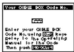

(continued)
Setting up cable box control (continued)
DSS receiver/Cable box brands and the corresponding cable box code numbers
If more than one code number is listed, try entering them one by one, until you come to the correct code for your equipment.
| DSS receiver brand | Code numbers | Cable box brand | Code numbers | Cable box brand | Code numbers |
| Sony | 650 | Jasco | 164, 326 | SL Marx | 051 |
| RCA | 577 | Jerrold | 014, 022, 025026, 035, 037058, 109, 287487 | Spectravision | 069 |
| Linsay | 451 | Sprucer | 032, 318 | ||
| Standard Components | 107, 166 | ||||
| Cable box brand | Code numbers | Macom | 044 | Starcom | 014, 026, 058109 |
| ABC | 018, 022, 024028, 217 | Magnavox | 038, 043, 080345 | Stargate | 026, 051 |
| Antronix | 218 | Memorex | 011 | STS | 167 |
| Archer | 033, 050, 164218 | Movie Time | 089, 167, 214 | Sylvania | 012 |
| BBT | 278 | Northcoast | 325 | T-Cable Teletext | 116 |
| Cable Star | 067 | Novaplex | 629 | Tandy | 269 |
| Cabletenna | 033 | NSC | 074, 081, 167214 | Tatung | 108 |
| Cable time | 172, 282, 388,459 | Oak | 018, 030259 | Teknica | 157 |
| Century | 164 | Omniview | 382 | Tele+1 | 454 |
| Citizen | 164, 326, 327 | Panasonic | 032, 118 | TeleCaption | 232 |
| Clyde Cablevision | 097 | Paragon | 011 | Teleservice | 292 |
| Color Voice | 036, 042 | Philips | 036, 038, 039040, 041, 042071, 301, 345 | Texscan | 012, 107 |
| Comband | 243, 244 | Philips ECG | 253 | TFC | 321 |
| Comtronics | 051, 071 | Pioneer | 034, 155, 271544, 695 | Timeless | 429 |
| Decsat | 434 | Popular Mechanics | 411 | Tocom | 023, 024, 070 |
| Diamond | 046 | Toshiba | 011 | ||
| Eagle Comtronics | 051 | Pulsar | 011 | Tudi | 297 |
| Eastern | 013, 285 | RCA | 032 | TV86 | 074 |
| Electricord | 089 | Realistic | 218 | TV COM | 018, 030, 259 |
| Electus | 055 | Recoton | 411 | Uniden | 236 |
| Filmnet | 454 | Regal | 031, 270, 284290 | Unika | 033, 164, 218 |
| Focus | 411 | Regency | 013 | United Artists | 018 |
| Garrard | 164 | Rembrandt | 081 | United Cable | 014 |
| GC Electronics | 027, 067, 341 | RK | 315, 317, 490 | Universal | 033, 050, 067088, 089, 164202, 218, 333 |
| GE | 243, 244 | Samsung | 051, 155 | Videoway | 261 |
| GEC | 097 | Satbox | 386 | Vidtech | 255 |
| Gemini | 026, 068, 081253 | Scientific Atlanta | 017, 019028, 288338 | Viewstar | 038, 071, 074,122, 222, 269300 |
| General Instrument | 022, 287, 487 | Seam | 521 | Wave Master | 576 |
| Hamlin | 020, 031, 045270, 284 | Sharp | 324 | Westminster cable | 116 |
| Hitachi | 022 | Signal | 051 | Zenith | 011, 065, 536 |
| Signature | 022 | Zentek | 411 |
Note
• Some cable boxes, even from brands listed on the right may not be compatible.
To ensure current operation
- Place the Cable Mouse so that it hangs out over the cable box/DSS receiver front.
- Do not place the cable box/DSS receiver on top of the VCR.
- Position the cable box/DSS receiver away from the VCR.
- Point the remote commander at the VCR, not at the cable box/DSS receiver.
![graph TD A["Remote Control"] -->|Signal flow| B["Device with Monitor"] B -->|Signal flow| C["Printer"] style A fill:#f9f,stroke:#333 style C fill:#bbf,stroke:#333 subgraph Side view D["Computer"] E["Monitor"] end](/content/2026/06/1301747/images/cfe2b5383e77249e0013a87856806c233e8bfb9335c494b4134f4c11ceecb018.jpg)
To check the cable box/DSS receiver control setting
1 Press CH +/- on the remote commander. Does the channel indicator on the cable box/DSS receiver change? (Point the remote commander at the VCR, not at the cable box/DSS receiver.) 2 Press all 10 number buttons (0 to 9) on the remote commander. Does the channel indicator on the cable box/DSS receiver change?
If the answer to both 1 and 2 is "yes," you have made the correct setting.
If you cannot get your VCR to control the cable box/DSS receiver
- Check that the Cable Mouse is connected to the CABLE BOX CONTROL jack on the VCR.
- Check the position of the Cable Mouse.
- Place the cable box/DSS receiver and VCR away from each other. Do not place the cable box/DSS receiver on top of the VCR.
- Try the setup again making sure to use the correct control code. If the cable box/DSS receiver still does not respond, try other codes.
Note
- Make sure to turn off the VCR when you plug in or unplug the Cable Mouse. If you unplug the Cable Mouse and plug it in again, turn on the VCR before you use the cable box control feature.
If your cable box still does not operate with the Cable Mouse, contact your cable company to see if they can provide you with a compatible cable box.
Setting up VCR Plus+
Example of "PlusCode"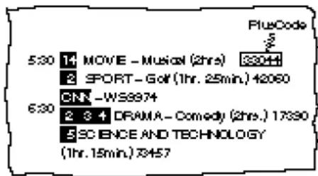
Example of "Channel Line-up Chart"
| CABLE CH | CABLE TV | VCR Plus+GUIDE CH |
| 16 | AM American Movie Classics | 35 |
| 17 | BRV Bravo (program grid only) | 54 |
| 20 | CNN Cable News Network | 42 |
| 21 | CSP C-SPAN | 28 |
| 22 | DS The Disney Channel | 53 |
| 25 | DSC The Decouy Channel | 37 |
| 34 | ESN ESPN | 34 |
| 35 | FAM The Family Channel | 47 |
| 5 | HED Home Box Phone | 33 |
| 27 | UF Lifetime | 46 |
| 29 | MAY Sports | 45 |
| 30 | MTV Music Television | 46 |
| 31 | NK Unitedodeon | 38 |
| 38 | SO Sports Channel | 59 |
| 39 | SCR Sports Channel America. | 70 |
| 45 | SHO Showtime | 41 |
| 17 | TES TBS SuperStation | 43 |
| 44 | TMC The Movie Channel | 58 |
| 49 | TNN The Nashville Network | 49 |
| 50 | TNT Tumen Network Television | 52 |
| 51 | USA USA Network | 44 |
How VCR Plus+ works
Whenever you want to record a TV program, all you need to do is look up the program's "PlusCode," a number assigned to each program that's published in the TV section of most newspapers, cable TV listings, and even TV GUIDE magazine. Then, just enter the PlusCode of the program you want and the VCR is automatically programmed to record that show. It's that simple.
How to set up your VCR
Setting up your VCR involves coordinating the TV channel number (the number you turn to on your TV or VCR to watch a program) with the guide channel (the number that's assigned to that channel in your program guide). To get the guide channel numbers, find the "Channel Line-up Chart" in the program guide for your area that features VCR PlusCodes. It usually looks like the example to the left.
For each channel your VCR receives, use the Channel Line-up Chart to check that the channel numbers match. For example, if HBO is listed in the Channel Line-up Chart on channel 33, and your VCR receives HBO on channel 15, you need to coordinate these numbers using the following procedure. For channels in which the numbers are the same, you can skip this procedure.


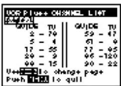
1 Press MENU, then press the CURSOR (↑/↓) buttons to move the cursor (I) to SET VCR Plus+ CHANNELS and press EXECUTE. When using the EASY SET UP procedure, skip this step. 2 Enter the guide channel number assigned in the program guide and press ENTER. The TV CH column is highlighted. 3 • If you made Hookup 1, 2, or 3, enter the actual number on your TV (and VCR) and press ENTER. • If you made Hookup 4, enter the cable output channel (usually 2, 3, or 4) and press ENTER. • If you made Hookup 5, enter the actual number on your TV (and VCR) for an unscrambled channel and press ENTER. For a scrambled channel, enter the cable box output channel (usually 2, 3, or 4) and press ENTER. 4 Repeat steps 3 and 4 for each channel whose numbers don't match. 5 When you have set all channels, press EXECUTE to confirm your channel settings. 6 When you've finished, press MENU to exit.


Basic Operations Playing a tape


Tips
- For further information on searching and playback functions, see "Playing/searching at various speeds" on page 44.
- If a cassette is inserted already, press POWER to turn on the VCR, then press ▶ PLAY to play a tape.
1 Turn on your TV and set it to the video channel:
- If the TV is connected to the VCR using the audio/video cable, set the TV to video input.
- If the TV is connected to the VCR using only the antenna cable, set the TV to the channel for the VCR.
2 Press ▲ EJECT to open the cassette panel.
3 Insert a cassette.
The VCR turns on.

To insert a Mini DV cassette, place it in the center of the tray.

Press ▷ PLAY to start playing.
When the tape reaches the end, it automatically rewinds to the beginning. (The power remains on.)
Additional tasks
| To | Press |
| Stop play | ■ STOP |
| Pause play | ■ PAUSE |
| Resume play after pause | ■ PAUSE or ▷ PLAY |
| Search forward | ⇨ SEARCH |
| Search backward | ⇨ SEARCH |
| Fast-forward the tape | ▶▶ FF during stop |
| Rewind the tape | ◀◀ REW during stop |
| View the picture during fast | ▶▶ FF during fast-forward◀◀ REW during rewind |
| Eject the tape | ▲ EJECT |
Recording TV programs

Tips
- To select channels, you can also use the number buttons on the remote commander. Enter the desired channel number using the number buttons, then press ENTER.
- If you don't want to watch TV while recording, you can turn off the TV. When using a cable box, make sure to leave it on.
Note
- If you insert a tape with its protect tab showing red – the VCR starts playing. To record on this tape, slide the tab so the red portion is not visible.
- the VCR ejects it when you press ● REC.
1 Turn on your TV and set it to the video channel:
- If the TV is connected to the VCR using the audio/video cable, set the TV to video input.
- If the TV is connected to the VCR using only the antenna cable, set the TV to the channel for the VCR.
- When using a cable box, turn it on.
2 Press ▲ EJECT to open the cassette panel.
3 Insert a cassette.
The VCR turns on. To insert a Mini DV cassette, place it in the center of the tray.
4 Press CH +/- to select the channel you want to record.
As you press CH +/-, the channel changes as follows:

To record a source connected to one of the inputs, select L1, L2 or DV.
5 Press ● REC to start recording.
When the tape reaches the end, it automatically rewinds to the beginning.
To stop recording
Press ■ STOP.
Watching a TV program while recording another
You can watch a TV program and record another at the same time. If the TV is connected to the VCR using the audio/video cable, set the TV to TV input.
If the TV is connected to the VCR using only the antenna cable, press TV/VTR to turn off the VTR indicator on the front panel, then select the desired channel on the TV.
Recording TV programs using VCR Plus+


Notes
- You cannot set a PlusCode in the following cases:
- When the VCR is turned off.
- While recording using the timer or quick timer.
- The timer will not accept settings in the following cases:
- When you select DAILY for a Saturday or Sunday program.
- When you select DAILY or WEEKLY for a program more than seven days ahead.
- When you enter PlusCode of a program that has already ended.
Just enter the program's "PlusCode" listed in the TV program guide. The date, times and channel of that program are set automatically. You can preset up to eight programs at a time.
Before you start...
- Check that the clock is set to the correct time.
- Insert a tape with its protect tab not slid to red. Make sure the tape is longer than the total recording time.
- Turn on your TV and set it to the video channel.
1 Slide down the back cover of the remote commander, then press VCR Plus+.
2 Press the PlusCode number buttons to enter the program's PlusCode.
If you make a mistake, press TIMER CLEAR and enter the correct PlusCode.

3 Press ONCE, DAILY, or WEEKLY:
To record Press
Only once ONCE
Everyday Monday to Friday DAILY
Once a week WEEKLY
The date, start and stop times, and channel number appear on the screen. Check that the information is correct. If it is not, press TIMER CLEAR to cancel.

4 To preset another timer setting, repeat steps 1 to 4.
5 Press POWER to turn off the VCR.
"TIMER" appears in the display window and the VCR stands by for recording. When using a cable box, leave it on.
Tip
- To cancel the procedure, press VCR Plus+ before pressing ONCE, DAILY, or WEEKLY.
Notes
- If the VCR beeps repeatedly, this means that: - The PlusCode is incorrect. - ONCE, DAILY, or WEEKLY was selected incorrectly. You cannot select DAILY or WEEKLY for a program that airs more than seven days ahead.
- If you timer record a program that is encoded with copyright protection signals, the VCR will continue recording but the video and audio signals will not be recorded on tape.
To stop recording
To stop the VCR while recording, press ■ STOP.
To use the VCR after setting the timer
To use the VCR before a timer recording begins, just press POWER. "TIMER" disappears and the VCR switches on. Remember to press POWER to reset the VCR in timer recording standby after using the VCR.
You can also do the following tasks while the VCR is recording:
- Reset the counter
- Display the tape counter on the TV screen with the DISPLAY button.
- Check the timer settings.
- Watch another TV program.
Setting the timer manually

Notes
- "TIMER" and the cassette mark flashes in the display window when you press POWER with no tape inserted.
- If you timer record a program that is encoded with copyright protection signals, the VCR will continue recording but the video and audio signals will not be recorded on tape.
If VCR Plus+ is not available in your area, follow the instructions below to set the timer to record programs.
Before you start...
- Check that the clock is set to correct time.
- Insert a tape with its protect tab not slid to red. Make sure the tape is longer than the total recording time.
- Turn on your TV and set it to the video channel.
- When using a cable box, turn it on.
1 Press MENU, then press the CURSOR (↑/↓) buttons to move the cursor (■) to TIMER SET/CHECK and press EXECUTE.
If the clock needs to be set, "Please set the clock" appears on the screen and the VCR automatically enters the clock setting mode.
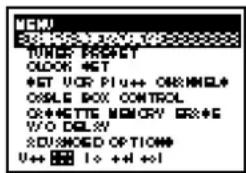
2 Set the date, start and stop times, and channel:
1 Press CURSOR → to highlight each item in turn. 2 Press CURSOR ↑/↓ to set each item. To correct a setting, press CURSOR ← to return to that setting and reset. To record a source connected to one of the inputs, select L1 or L2 in the "CH" position.

3 Press CURSOR → to confirm the setting.
The cursor (■) appears in the leftmost column.
To preset another timer setting, move the cursor to the next line and repeat steps 2 and 3.

4 Press EXECUTE.
5 Press POWER to turn off the VCR.
"TIMER" appears in the display window and the VCR stands by for recording. When using a cable box, leave it on.
Tips
- To set the channel for timer recording, you can also use CH +/- or the number buttons.
- To change or correct a setting before confirming it, press CURSOR ← to highlight the item you want to change and reset it.
To stop recording
To stop the VCR while recording, press ■ STOP.
Daily/weekly recording
When you set the date to start recording in step 2 above, press CURSOR ↓ to select the recording pattern. Each time you press the button, the indication changes as follows.
the current date → SUN-SAT → MON-SAT → MON-FRI
→ EVERY SAT ..... → EVERY MON → EVERY SUN
→ 1 month later → (dates count down) → the current date
SUN-SAT (from Sunday to Saturday)
MON-SAT (from Monday to Saturday)
MON-FRI (from Monday to Friday)
EVERY SAT (every Saturday)
EVERY MON (every Monday)
EVERY SUN (every Sunday)
Additional operations Playing/searching at various speeds


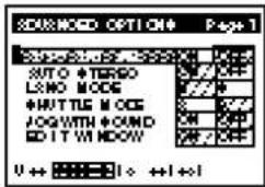
- If you want to hear the sound during slow motion and frame by frame set JOG WITH SOUND in the ADVANCED OPTIONS menu to ON (page 54).
Using buttons on the remote commander
| Playback options | Operation |
| Play at twice the normal speed | During playback, press · 2.To change direction, press FRAME ◀ or ||►. |
| Viewing in a high-speed picture | During playback, press ◀ or ►►. |
| Play in slow motion | During playback or pause, press ► SLOW .To change direction, press FRAME ◀ or ||►. |
| Play frame by frame | During pause, press FRAME ◀ or ||►. |
To resume normal playback
Press ▷PLAY.
Using shuttle ring
| Playback options | Operation |
| Play at various speeds | During playback or pause:Turn the shuttle ring and hold it at the speed you want.1/5: 1/5 of normal speed1: normal speed·2: double speed ∅/∅ : approximately 10 or 25 times normal speedThe VCR switches between the two speeds as you turn the shuttle ring. |
| Fast-forward/rewind | During stop:Turn the shuttle ring on the VCR to or and release.Turn the shuttle ring to or again to view the picture during fast-forward or rewind.* |
* This feature is not available when using a remote commander or when controlling another VCR from this VCR.
To resume normal playback
Press ▷PLAY.
Using jog dial
During playback or pause, turn the jog dial to play the picture at a speed slower than normal speed. This feature is useful for locating a specific point on the tape.
Rewinding the tape and starting playback automatically
During stop, press ▷ while pressing ◀ on the control panel. The tape rewinds to the beginning (▷ flashes), then starts playing automatically.
Displaying tape information

Tip
- The display appears on the TV screen indicating information about the tape, but the information will not be recorded on the tape.
Notes
- The counter resets to "0H00M00S" whenever a tape is reinserted. • The counter stops counting when it comes to a portion with no recording.
- The counter indication may be inaccurate when a tape that has blank portions is rewound or fast-forwarded repeatedly.
- During fast-forward, rewind, or search, the tape speed automatically adjusts to the remaining amount of tape. In these cases, the counter or time code indication may stop momentarily.
- Use the remaining time display as an approximate indication. In rare cases, depending on the tape type, the indication may be inaccurate.
Displaying the recording data
When recording with the digital VCR, data such as the recording date, time and the channel number are also recorded onto the tape at the same time. If you play back a tape recorded with a Sony digital camcorder, you can check the shutter speed, program AE mode, white balance, iris and gain.
To display the recording data, press DATA CODE during playback. Each time you press DATA CODE, the display changes as follows. The data appears only during playback.
![graph TD A["Data display off"] --> B["Recording data and time"] B --> C["Sony camcorder settings\nShutter speed, AE mode, White balance, Gain\nWhen the tape was recorded on this VCR, “---” appears instead."]](/content/2026/06/1301747/images/e3ed158ed382aa177f56e35beae89cca8704edb636c0cef2ddf2124910c8bdfa.jpg)
Displaying the remaining tape counter
When a tape is inserted, each time you press COUNTER SELECT, the tape counter, the time code, and the remaining time counter appear in sequence. To display them on the TV screen, press DISPLAY to turn the display on, then press COUNTER SELECT.
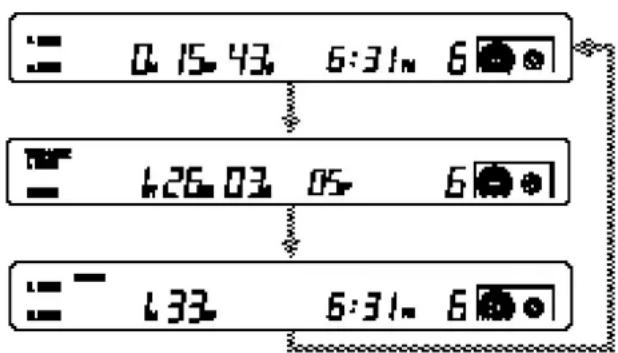
Using the tape counter
Press COUNTER SELECT to display the tape counter. At the point on a tape that you want to find later, press COUNTER RESET on the operation panel to reset the counter to "0H00M00S." Search for the point afterwards by referring to the counter.
Selecting the sound
Playing stereo or bilingual programs
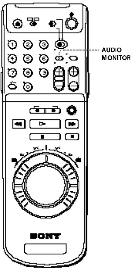
Press AUDIO MONITOR to select the desired sound. Each press of the button changes the display on the VCR.

Playing the desired audio track
When listening to a tape on which commentary or background music has been recorded afterwards, you can specify the playback audio tracks.
This function is available when playing back a tape recorded in 12-bit audio recording mode.
For details, see page 84.
1 Press ▷ PLAY. 2 Select the position corresponding to the desired audio tracks with the AUDIO MONITOR selector on the control panel.
- To listen to stereo 1 track: set to STEREO 1.
- To listen to stereo 2 track: set to STEREO 2.
- To listen to both stereo 1 and stereo 2 tracks: set to MIX.
You can adjust the audio balance between the stereo 1 track and stereo 2 track by using the AUDIO MIX BALANCE control when you select "MIX."

Notes
- When you connect the VCR to the TV with only the antenna cable, the sound is always heard in mono.
- When you play back a tape recorded in the 12-bit mode, "STEREO 1" always appears in the display window regardless of the Audio Monitor setting.
Recording stereo and bilingual programs
Tips
- When a stereo program is received, the STEREO indicator lights up. When a bilingual program is received, the BILINGUAL indicator lights up.
- You can also use the AUDIO MONITOR selector on the control panel to monitor the sound when recording from the DV input. The selector setting will not affect the sound recorded.
- For information on how the VCR records sound, see "How the audio mode is decided" on page 61.
Note
- Set SAP in the ADVANCED OPTIONS menu to MAIN (page 54) when not recording SAP sound, or no sound will be recorded on the right audio track.
Recording stereo programs
This VCR automatically receives and records stereo programs. When a stereo program is received, the STEREO indicator lights up. If there is noise in the stereo program, set AUTO STEREO in the ADVANCED OPTIONS menu to OFF. The sound will be recorded in monaural but with less noise. For details, see page 55.
Recording bilingual programs
Normally, this VCR records only the main sound. To record SAP (Second Audio Program) sound, set SAP in the ADVANCED OPTIONS menu to AUTO (the SAP indicator lights up). For details, see page 56.
To select the bilingual sound while recording
Press AUDIO MONITOR to select the sound you want. This operation does not affect the recording.
Selecting the sound during playback
Press AUDIO MONITOR to select the sound you want.
| Indicator | Selected dound STEREO | BILINGUAL |
| MAIN/L and SUB/R or STEREO | STEREO | MAIN and SAP |
| MAIN/L | LEFT channel | MAIN |
| SUB/R | RIGHT channel | SAP |
Recording TV programs using the quick timer

Tip
- You can also set the quick timer and start recording when the VCR is in stop mode. Recording starts when you press QUICK TIMER more than twice.
Note
- When you set the quick timer while the time code is displayed, the remaining recording time and the current time appear in the display window.
After starting recording in the normal way, you can have the VCR stop recording automatically after a specified duration.
1 While recording, press QUICK TIMER once.

2 Press QUICK TIMER repeatedly to set the duration.
Each press advances the time in increments of 30 minutes.

The duration decreases minute by minute to 0:00, then the VCR stops recording and turns off automatically.
To extend the duration
Press QUICK TIMER repeatedly to set the new duration.
To stop recording
To stop the VCR while recording, press ■ STOP.
Searching using the index function

Note
- When searching in order of the actual positions of the recordings on the tape, an index signal close to the current position may not be located.
The VCR marks the tape with an index signal at the point where each recording begins. Using these signals as references, you can find a specific recording. There are three kinds of search:
- Searching the beginnings of recordings: Index search
- Searching a point on the tape where the recorded date changes: Date search
- Searching for scenes recorded in the photo mode with a digital camcorder: Photo search
Searching in the list
If the tape has a cassette memory, the recordings are listed in the chronological order in which they were made. You can search using this chronological list.
If the tape does not have a cassette memory, you cannot search for scenes in chronological order.
1 Press SEARCH SELECT to select the search type: INDEX, DATE, or PHOTO SEARCH.
The indicator of the search type you selected lights. The chronological list appears on the monitor screen.

2 Press ◀◀◀ or ▶▶◀ to select a recording.
The VCR starts searching and when it locates the recording, begins playback. During Photo search, the VCR pauses.

Searching in the order of the actual positions of the recordings on the tape
When you use a tape without a cassette memory, the VCR searches in the order of the actual positions of the recordings, regardless of the setting of CASSETTE MEMORY in the ADVANCED OPTIONS menu. When you use a tape with a cassette memory, set CASSETTE MEMORY in the ADVANCED OPTIONS menu to "OFF" (page 54).
1 Press SEARCH SELECT to select the search type.
The indicator of the search type you selected lights.
2 Press I◀◀ or ▶▶I repeatedly to locate the recording you want.
The VCR starts searching backwards or forwards until the index number comes to zero, then plays back the recording. During Photo search, the VCR pauses.

(continued)
Searching using the index function (continued)
Tips
- If the search type is not displayed on the TV screen, press the DISPLAY button on the remote commander.
- If you use a tape with the CIII4K mark, the cassette memory stores up to 33 index signals. (The number changes depending on the combination of index, date, and photo data stored.) This VCR is capable of storing and retrieving up to 16 kbits of cassette memory.
- To locate recordings whose signals are not stored in the cassette memory, or to locate recordings in order of their position on the tape, set CASSETTE MEMORY in the ADVANCED OPTIONS menu to "OFF." Use the procedure for "Searching in order of the actual positions of the recordings on the tape" to search for a recording.
- You can also search for programs using the "Index Tieler" signal, but the data such as the recording date and time and the title does not appear in the display window.
Notes
• Each program is indexed at its beginning. If you record another program over the beginning of the first program, you will not be able to search the original program.

- Searching may not be done correctly if the signal was not recorded on a Sony-brand digital video equipment.
How signals are recorded
The VCR marks the tape when:
– Recording starts from the stop mode. - Recording is resumed after changing the program position during recording pause. – Timer recording starts.
There are three different signals for each search method. The type of signal recorded and where it is recorded (on the tape itself or in the cassette memory) depends on the video equipment used for recordings. Please note that if the signals for certain search type are not recorded, you cannot do that type of search.
When you record on this VCR
| Signals for In cassette memory On tape |
| Index search Yes Yes |
| Date search No Yes |
| Photo search No No |
When you record with a Sony digital camcorder (DCR-VX1000/VX700/PC7*)
| Signals for In cassette memory On tape |
| Index search No No |
| Date search Yes Yes |
| Photo search Yes Yes |
* The index signal cannot be recorded in the cassette memory (DCR-PC7 only).
Checking/changing/cancelling timer settings


Tip
- To check the settings, you can also use the TIMER CHECK button on the rear of the remote commander. Turn on the VCR and press TIMER CHECK. The TIMER SET/CHECK screen appears.
Before you start...
- Turn on your TV and set it to the video channel.
1 Press POWER to turn on the VCR.
2 Press MENU and select TIMER SET/CHECK.
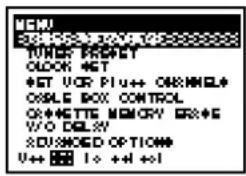
3 Check the timer settings:
- If you do not want to change or cancel the settings, press EXECUTE, then turn the VCR off to return to recording standby.
- If you want to change or cancel the settings, press the CURSOR (↑/↓) buttons to move the cursor (■) to the setting you want to change or cancel.
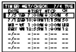
4 Change or cancel the timer setting:
- To change the setting, press the CURSOR (←/→) buttons to highlight the item you want to change, and reset it using the CURSOR (↑/↓) buttons. Then, press CURSOR → to move the cursor to the leftmost column.
- To cancel the setting, press the TIMER CLEAR button on the rear of the remote commander.

5 Press EXECUTE.
If any settings remain, turn off the VCR to return to recording standby.
Checking/changing/cancelling timer settings (continued)
When the timer settings overlap
When the timer settings are overlapped, overlapped programs or part painted as below are not recorded.
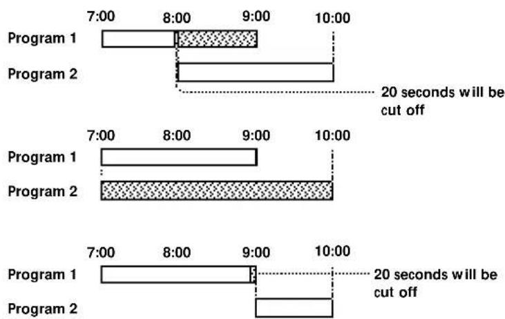
Adjusting the picture (Y/C delay)

When playing back a source recorded from an analog VCR, the color of the picture may shift right or left.
You can adjust this color shift by using the Y/C delay function.
The Y/C delay function works when playing back or viewing the input from the DV connector.
1 During playback or pause or when the DV input is displayed, press MENU. 2 Press the CURSOR (↑/↓) buttons to move the cursor (■) to Y/C DELAY, then press EXECUTE. 3 Press the CURSOR (←/→) buttons to correct the color shift of the picture. 4 Press EXECUTE to return to the original screen.


Tips
• The video signals are composed of Y (luminance) and C (chrominance) signals. The Y/C delay function adjusts the time lag between Y and C signals. - You cannot record the adjusted picture.
Changing menu options

Tips
- The menu settings are held until the AC plug is disconnected.
1 Press MENU.
2 Press the CURSOR (↑/↓) buttons to move the cursor (■) to ADVANCED OPTIONS, then press EXECUTE.
The ADVANCED OPTIONS menu appears on the TV screen.
3 Press the CURSOR (↑/↓) buttons to move the cursor (■) to the option you want to change.
If you press ↓ at the lowest line, the next page appears.

Page 1
Page 2
4 Press CURSOR (←/→) to change the setting.
5 Press EXECUTE to return to the original screen.
Menu choices
Initial settings are indicated ● mark.
Page 1
| Menu option | Set this option to |
| AUTO ANT SEL | ● ON if your TV is connected only to VHF/UHF OUT on the VCR. To play a tape, set the TV to the VCR channel (channel 3 or 4). |
| OFF if your TV is connected to both VHF/UHF OUT and LINE OUT on the VCR. To play a tape, set the TV to VCR input. | |
| AUTO STEREO | ● ON to receive stereo programs. |
| OFF to reduce noise in a stereo program. Although the sound may improve, the sound becomes monaural. | |
| LANC MODE | ● M to control another VCR from this VCR using the ◆LANC connection. |
| S to control this VCR from another equipment using the ◆LANC connection. | |
| SHUTTLE MODE | A to control, via the ◆LANC connection a VCR that doesn’t have a reverse slow motion function. |
| ● B to control, via the ◆LANC connection VCR that has a reverse slow motion function. | |
| JOG WITH SOUND | ON to listen to the sound when playing the tape frame by frame or at a slower speed than normal. |
| ● OFF to turn off the sound. | |
| EDIT WINDOW | ● ON to turn on the on-screen window display for assemble editing. |
| OFF to turn off the on-screen window display for assemble editing. |
Note
- When you connect a video printer and use the PRINT button on the remote commander supplied with this VCR, set LANC MODE to "S."
Changing menu options (continued)
Notes
- When recording TV programs, the audio recording mode is automatically set to 16-bit mode.
- When recording from the DV jack, the audio recording mode is automatically set to the same mode as the input audio.
| Menu option | Set this option to |
| DIMMER | ON to make the display window dim. |
| OFF to make it brighter. | |
| LINE IN AUDIO | 16 to record the audio in 16-bit recording mode. |
| 12 to record the audio in 12-bit recording mode. | |
| SAP | AUTO to record SAP sound. |
| OFF to record the main sound. | |
| L1 IN VIDEO | S to select the S-video signal when both the S-video and video jacks are connected. The video signal is selected automatically when only the video jack is connected. |
| NORM to select the video signal when both the S-video and video jacks are connected.(When you use the S-video picture, make sure to set to “S.”) | |
| CASSETTE MEMORY | AUTO to search the recording with the cassette memory. If the tape does not have a cassette memory, the VCR will search recordings using index signals recorded on the tape itself. |
| OFF to search recordings using the index signals recorded on the tape at all times. |
Erasing the cassette memory
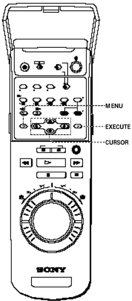
Some DV cassettes and Mini DV cassettes have cassette memories where data such as recorded date and time is stored. If you don't need the stored data, erase the memory with the following procedure.
1 Press MENU.
2 Press the CURSOR (↑/↓) buttons to move the CURSOR (I) to CASSETTE MEMORY ERASE, then press EXECUTE.

3 Press the CURSOR (↑/↓) buttons to select the data to erase, then press CURSOR (←/→) to set it to YES.

Select To erase
ALL DATA The entire memory
INDEX DATA Signals for INDEX SEARCH
DATE DATA Signals for DATE SEARCH
PHOTO DATA Signals for PHOTO SEARCH
4 Press EXECUTE.
A message appears to confirm the operation.

5 Press EXECUTE.
The data you selected is erased, then the VCR returns to the original screen.
Notes
- You cannot erase the cassette memory while the protect tab on the cassette is slid to show red.
- If the cassette memory is larger than 16kbits, you can select ALL DATA only.
Editing Before editing
Editing methods
This section introduces you to various ways to edit tape recordings. You can cut out unwanted scenes or assemble your favorite scenes in the order you prefer. To edit tapes, you need to connect another VCR or camcorder.
Copying a whole tape
You can copy the contents of one tape to another.

Cutting out unwanted scenes
While making a copy of a tape, you can cut out unwanted scenes.

Assemble editing
You can select various scenes from a source tape and record them in any order you choose.
To use this function, you need a VCR equipped with a LANC jack.
![graph TD A["Source tape"] --> B["Video"] B --> C["Audio"] C --> D["Edited tape"] D --> E["Video"] E --> F["Audio"] F --> G["Edited tape"] style A fill:#f9f,stroke:#333 style D fill:#ccf,stroke:#333](/content/2026/06/1301747/images/12bb3882bb26e26e504ad46408f1ed85af227ff18d01349c7b9f7f75014d532e.jpg)
Note
- Use a source tape recorded on this VCR for insert editing. Otherwise, editing may result in poor sound and picture. If the source tape was recorded on another VCR (including other DHR-1000s), copy the tape on this VCR and use the copied tape.
Tips
- By executing video insert and audio insert editing at the same time, you can replace both the video and the audio at the same time. - With this VCR, you can execute V.O.S (video on sound editing), where you can record audio first, then insert video to match the previously recorded audio.
Insert editing
You can replace an existing scene with material from another recording. For insert editing, use this VCR as the recording machine. The following methods of insert editing are available with this VCR.
Video insert editing
You can replace an existing scene with another recording, retaining the sound.

Audio insert editing (16-bit mode)
The VCR replaces the original audio with 16-bit mode audio, while retaining the picture.

Audio insert editing (12-bit mode)
The VCR replaces the original audio with 12-bit mode audio, while retaining the picture.
With 12-bit mode, you can select the track, stereo 1 or 2 track, to be replaced.
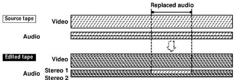
(continued)
Before editing (continued)
Audio dubbing
You can add commentary or background music to a tape recorded in 12-bit audio mode. The sound is recorded on the stereo 2 track.
Note
- Use a source tape recorded on this VCR for insert editing. Otherwise, editing may result in poor sound and picture. If the source tape was recorded on another VCR (including other DHR-1000s), copy the tape on this VCR and use the copied tape.
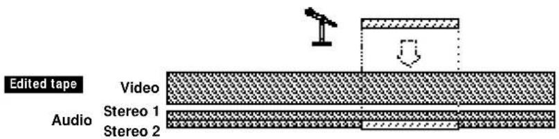
12-bit/16-bit audio modes
When using the DV standard VCR, the sound is recorded in either 12-bit or 16-bit mode.
Tip
- The DCR-VX1000/VX700/PC7 digital video camera recorders record the sound in 12-bit audio mode (Stereo 1).

The 12-bit mode consists of two separate stereo tracks — Stereo 1 and 2.

The 16-bit mode uses the whole audio area to record one stereo track.
Checking the audio mode
During playback, the indicator corresponding to the audio mode lights up.

How the audio mode is decided
The audio mode depends on the recording source or connection.
- When recording from the DV jack: the sound is recorded in the same audio mode as the source tape.
- When recording from the LINE IN connectors: you can select the audio mode by setting LINE IN AUDIO in the ADVANCED OPTIONS menu (on page 54).
- When recording TV programs using the tuner of this VCR: the sound is recorded in 16-bit mode.
(continued)
Before editing (continued)
Tips
- If the other VCR has a LANC jack of 5-pin DIN type, connect with the VK-810 Control L connecting cable (not supplied). • The jacks labeled CONTROL L or REMOTE have the same function as LANC jacks.
Notes
- The VCR (recorder) receives the time code data from the LANC jack only when the other VCR (player) is set to show the time code indications.
- If this VCR cannot control the other VCR, check the settings of "LANC MODE" and "SHUTTLE MODE" on both VCRs.
- The time code of this VCR follows the Drop Frame mode. To correct the error, the time codes may not be displayed on some frames.
Notes
- With the DV connection, the sound is recorded in the same audio mode as the source tape. To record in a different audio mode from the source tape, use the LINE connection instead.
- The DV jack of this VCR outputs playback video and audio signals only. Signals from the VCR's tuner or line inputs are not output from the DV jack.
- If you insert the sound on the stereo 2 track of the picture under the following conditions, the inserted sound will be muted even if you select to listen to both sound on stereo 1 track and stereo 2 track: You make the player VCR enter the playback pause mode, or slow or high-speed playback, and then record that picture on this VCR with the DV connection.
Tip
- With the DV connection, the playback VCR transmits the recording data on the source tape. So when you play back the recorded tape and press the DATA CODE button, the same time and input data as on the source tape is displayed.
Connectors and features used for editing
LANC jack
The LANC (Local Application Control) connection lets you control the connected equipment for easier editing. The LANC connection transmits signals such as control signals, status data and time code data. When connecting VCRs with the LANC cable, you need to set the LANC mode for each VCR.
- On the VCR that controls the other VCR: set LANC mode to "M."
- On the VCR to be controlled from the other VCR or editing machine: set LANC mode to "S."
In a case of a commander that does not have a LANC mode switch or a LANC mode menu, LANC mode is usually set to "S."
Time code
Time codes are signals recorded on the tape so that you can precisely specify a point on the tape. This signal is recorded on the tape for every frame (about 30 frames per second). On this VCR, time codes are recorded automatically during recording.
To check the time code, press COUNTER SELECT until the TIME CODE appears in the display window.
Time code indication
Usually, the time code is recorded consecutively from "0H00M00S00F," from the beginning of the tape. However, if there are blank sections in the tape, time codes are recorded out of sequence and assemble editing will not function correctly. To prevent this, first copy the source tape and use the copied tape for editing. The time code will be recorded consecutively on the copied tape.
DV connection
The DV jack transmits video and audio signals in digital form.
The video and audio signals are sent with hardly any degradation, enabling high-quality editing. The signal flow is automatically detected so you do not need to make separate connections for input and output.
Because more data is sent through the DV connection compared to the LINE connection, some features are not available with this connection.
- The on-screen display of the other VCR cannot be sent with the DV input picture. To view the on-screen display, connect the other VCR directly to a TV. – Picture adjustments made on the other VCR, such as Y/C delay cannot be sent with the DV input picture. The other VCR's playback picture is recorded on this VCR in its original state.
- If you playback/record both of the main and sub tracks, the mixed sound is output/recorded from the DV jack regardless of the Audio Monitor setting. The Audio Monitor setting is effective only when you playback/record the analog signal.
- Contents of the cassette memory are not transmitted.
- If the source tape is played back at speeds other than normal, the audio signals are not transmitted.
Selecting the connection for your VCR
Before editing, check whether the other VCR has a ⬆LANC jack or not. The operating procedures differ depending on whether or not you make the ⬆LANC connection.
To use the assemble editing feature, you need to connect to a VCR equipped with a ⬆LANC jack.
Does the other VCR have a ⬇LANC jack?

Yes → go to "Editing with LANC cable – Connections" page 64. No → go to "Editing without LANC cable – Connections" page 77.
When using this VCR as the playback machine
In the following pages, editing procedures are explained using this VCR as the recording machine. To use this VCR as the playback machine, note the following:
- When connecting the ⬆LANC jack, set LANC MODE in the ADVANCED OPTIONS menu to "S" (page 54).
- If the other VCR has the time code function, press DISPLAY on this VCR so that the time code counter appears in the display window.
- If you play back an audio dubbed tape and connect the other VCR to this VCR's LINE OUT jacks, set the AUDIO MONITOR selector on the VCR to MIX. Then select the precise balance between the tracks with the AUDIO MIX BALANCE control.
For further instructions, refer to the manual of the recording VCR or the editing controller.
(continued)
Connections
Notes
- If you connect both LANC jacks on the front and rear panel, the front one is selected.
- When you connect the other VCR using the DV jack, index signals, and the contents of the cassette memory are not transmitted.
To a digital VCR with DV jack
With this connection, you can edit tapes with high-quality video and audio.
![graph TD A["Player"] --> B["Digital VCR (Camcorder)"] B --> C["TV"] C --> D["Recorder"] D --> E["This VCR"] E --> F["DV INOUT"] E --> G["DC/W/DC"] F --> H["LVNC cable (supplied)"] G --> I["LVNC cable (not supplied)"] H --> J["DV connecting cable (supplied)"] I --> J J --> K["Signal flow"]](/content/2026/06/1301747/images/b8b7f317be8962403828550a9988e8ed17ecdcbcbe2c3f7dbdeb162bb8a54f16.jpg)
Notes
- If you connect both LINE IN and LINE OUT jacks of this VCR to the other VCR, select the input correctly to prevent a humming noise.
- If you connect the cables to both the LINE-1 IN VIDEO and LINE-1 IN S-VIDEO jacks, the signal from the S-VIDEO jack is sent to the VCR and "S" lights in the display window. If you want to use the video signal from the VIDEO jack, set L1 IN VIDEO in the ADVANCED OPTIONS menu to "NORM" (page 54).
To a VCR without DV jack
If you do not need to change connections frequently, connect to the LINE-1 IN jacks on the rear of this VCR.
![graph TD A["Player"] --> B["Another VCR"] B --> C["TV"] C --> D["Recorder"] D --> E["This VCR"] E --> F["LANC cable (supplied)"] F --> G["Audio/video cable (supplied)"] G --> H["S-video cable (supplied, when the other VCR has a S-VIDEO OUT jack)"] H --> I["LANC OUT"] I --> J["Line 1"] J --> K["L-MIN…](/content/2026/06/1301747/images/4de4ff19090703b5949fd72f24a3a0ff2a047eec4b9b6f06de7adbfb1017089a.jpg)
: Signal flow
Note
- Distorted signals (e.g., when played back at a speed other than normal) will not be recorded properly.
To a camcorder without DV jack
The LINE-2 IN jacks on the front of the VCR are convenient if you connect or disconnect a camcorder frequently.
Tip
- To connect a monaural VCR, use the LINE-2 IN jack and connect to the L jack (white) (leave the red audio plug unconnected). The monaural audio from the L jack will be recorded on both left and right tracks.
Notes
- If you connect the cables to both the LINE-2 IN VIDEO and LINE-2 IN S-VIDEO jacks, the signal from the S-VIDEO jack is sent to the VCR and "S" lights in the display window. If you want to use the video signal from the VIDEO jack, set L2 IN VIDEO in the ADVANCED OPTIONS menu to "NORM" (page 54).
- Distorted signals (e.g., when played back at a speed other than normal) will not be recorded properly.
Tips
• Editing is not possible with a tape that is copyright protected. - When you finish editing, set the EDIT switch to "OFF."
Tip
• LANC mode of camcorders is usually fixed to S.
![graph TD A["Player"] --> B["Camcorder"] B --> C["TV"] C --> D["This VCR"] D --> E["LANC cable (supplied)"] E --> F["Audio/video cable (supplied)"] F --> G["S-video cable (supplied, when the other VCR has a S-VIDEO OUT jack)"] G --> H["S-VIDEO OUT jack"] H --> I["LANC cable (supplied)"] I --> J["Audi…](/content/2026/06/1301747/images/d0125727df55de77e89ddda3000c6c899942d4ba45d19d5a3962cd32878b1158.jpg)
Preparation
On the player
- Insert a source tape.
- If the player VCR has an EDIT switch, set it to ON.
- Set LANC mode to "S."
- Turn off the on-screen display.
On the recorder (this VCR)
- Insert a tape.
- Press INPUT SELECT so that the jack to which the player is connected appears in the display window: "DV," "L1," or "L2"
- Set LANC mode to "M."
1 Press MENU. The MENU screen appears on the TV screen. 2 Select ADVANCED OPTIONS by pressing CURSOR (↑/↓) buttons and press EXECUTE. 3 Select LANC MODE by pressing CURSOR (↑/↓) buttons. 4 Select M by pressing CURSOR (←/→) buttons. 5 Press EXECUTE.
(continued)
Connections (continued)
Tip
- For the DCR-VX1000/VX700/PC7 digital video camera, set SHUTTLE MODE to "B."
Notes
• The REC LEVEL and REC BALANCE controls do not function on a source input through the DV jack. - With the DV connection, the playback VCR's AUDIO MONITOR and AUDIO MIX BALANCE do not function on the source audio output through the DV jack.
- Set the shuttle mode.
1 Press MENU.
The MENU screen appears on the TV screen.
2 Select ADVANCED OPTIONS by pressing CURSOR (↑/↓) buttons and press EXECUTE. 3 Select SHUTTLE MODE by pressing CURSOR (↑/↓) buttons. 4 Select "A" or "B" by pressing CURSOR (←/→) buttons.
A: When slow playback in reverse direction is not available on the other VCR.
B: When slow playback in reverse direction is available on the other VCR.
5 Press EXECUTE.
- When you connect to the LINE 1/2 IN jacks, select the audio recording mode.
1 Press MENU.
The MENU screen appears on the TV screen.
2 Select ADVANCED OPTIONS by pressing CURSOR (↑/↓) buttons and press EXECUTE. 3 Select LINE IN AUDIO by pressing CURSOR (↑/↓) buttons. 4 Select 16 or 12 by pressing CURSOR (←/→) buttons.
16: When you want higher-quality sound and need not add sound later. 12: When you want to add sound later with insert editing or audio dubbing.
If you are going to make insert recording, select the original mode of the recording tape.
- When you connect to the LINE 1/2 IN jacks, adjust the recording level and balance with the REC LEVEL and REC BALANCE controls. Play back the source, then adjust the controls so that the red indicators of the level meter do not light up. Select the balance according to your need (normally, set it to the center).
Controlling the other VCR with LANC connection
With the LANC connection, you can control the other VCR by using the operation panel of this VCR (synchronized editing feature).
Notes
- The VCR (recorder) receives the time code data from the LANC jack only when the other VCR (player) is set to show the time code indications.
- If this VCR cannot control the other VCR, check the settings of "LANC MODE" and "SHUTTLE MODE" on both VCRs.

Copying a tape
With this function, the tapes in both VCRs are rewound to the beginning, then the source tape is copied until one of the tapes reaches its end. If you want to start copying from the middle of the tape, see page 68.
Before you start editing, set up the system according to the instructions on pages 64 to 66.

1 Press DUPLICATE ENTIRE TAPE.
The indicator lights up.
To cancel copying, press DUPLICATE
ENTIRE TAPE again.
2 Press START/PAUSE.
Both tapes are rewound to the
beginning. The source tape starts
playing, and a few seconds later, this
VCR starts recording.
When either tape reaches its end, both tapes stop.
tapes stop.
Note
• The first few seconds may not be recorded.
To stop copying
To stop while copying, press ■ (STOP).
Cutting out unwanted scenes
With this function, you can start editing from the middle of the tape, and cut out unwanted scenes while making a copy.
Before you start editing, set up the system according to the instructions on pages 64 to 66.


1 Search for the points where you want to start playing or recording, and set both VCRs to playback pause mode. 2 Press EDIT STANDBY.
The EDIT STANDBY indicator lights. This VCR is set to recording pause, and the other VCR is set to playback pause.
3 Press START/PAUSE.
Playback starts on the other VCR and recording starts on this VCR.
4 Press START/PAUSE just before the beginning of the unwanted scene (A).
Both VCRs are set to pause.
If the tape passes the desired point
Press RECORDER and rewind the tape to point Ⓐ, with the shuttle ring or jog dial.
Notes
- If you press ■ STOP to stop editing, the source picture may be recorded after it stops.
- This procedure is not possible if you connect this VCR to the DCR-VX1000/VX700/PC7 digital video camera via the DV cable and you use this VCR as the playback machine.
- If you record on the beginning part of the tape, or on the part just after an unrecorded portion, the first part of the recording may be dropped.
- When you record on a new or fully rewound tape, do a trial recording for about 15 seconds, then start the actual recording. If you start the actual recording from the beginning of the tape, the first part may not be recorded when you play back the tape on another VCR.
5 Search for the point to resume recording (®).
1 Press PLAYER and start playing the tape. 2 Locate the point with the jog dial or shuttle ring. 3 Set the other VCR to playback pause.

6 Press START/PAUSE to resume recording.
7 To cut out other scenes, repeat steps 4 to 6.
8 To finish editing, press START/PAUSE to set the VCRs to recording pause, then press EDIT STANDBY.
Both VCRs stop.
Assemble editing
You can select various scenes called "events" from a source tape and record them in any order you choose. You can edit up to 10 events at a time.
Before you start editing, set up the system according to the instructions on pages 64 to 66.

Tip
- If you do not want to display the edit window, set EDIT WINDOW in the ADVANCED OPTIONS menu to OFF (page 54). The editing procedure is the same as when editing with the Edit Window.
Note
• Horizontal lines may appear in the top left (or right) screen. However, this will not affect the edited picture.
Looking at the Edit Window
The Edit Window appears during assemble editing and shows the events you have chosen. 5 events are displayed at a time for a total of 10 events.
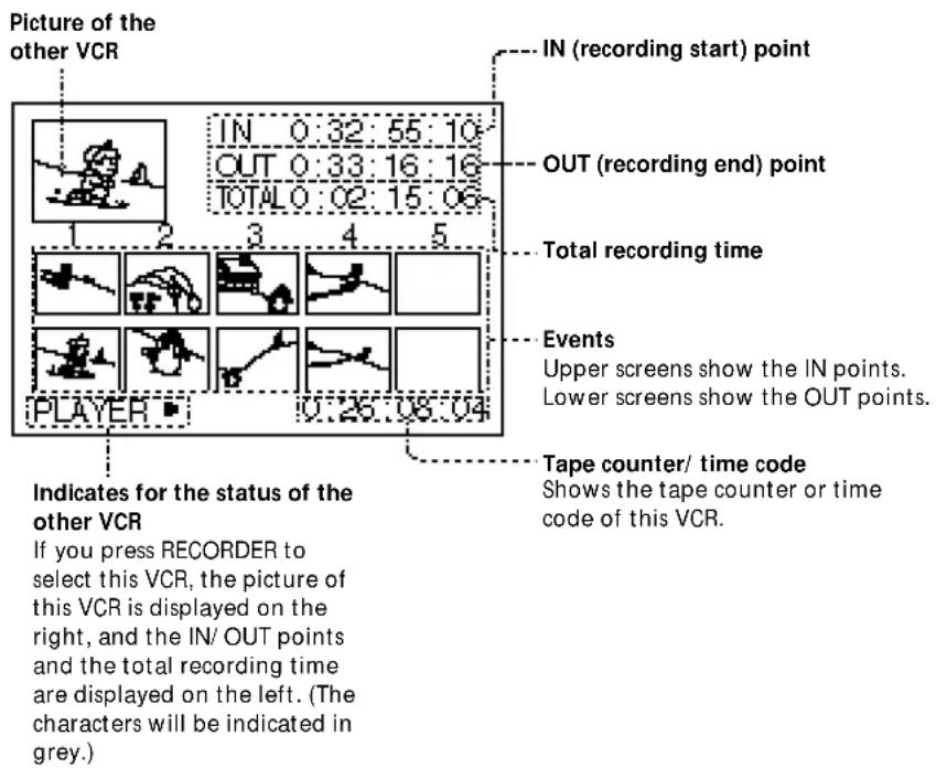
Notes
- If the remaining time appears in the display window of the main unit, you cannot execute assemble editing.
- Do not select another input while assemble editing is being executed. Editing may not function correctly.
- This VCR may malfunction if the IN/OUT points are not separated by more than two seconds.
- If an event you want to record is marked with a time code of less than 0:01:00:00, the event will be edited inaccurately. In this case, use the manual editing procedure.
- If the time code of the other VCR is displayed as "-:-:- :—" during fast-forward or rewind, assemble edit may not function.
- You cannot press PLAYER while this VCR is in playback mode.
- Do not press MARK while the other VCR is in stop mode. Assemble editing may not function correctly.
- If you record over a previous recording, the end of the new recording will not continue on to the original recording smoothly.
- If you record on the beginning part of the tape, or on the part just after an unrecorded portion, the first part of the recording may be dropped.
- When you record on a new or fully rewound tape, do a trial recording for about 15 seconds, then start the actual recording. If you start the actual recording from the beginning of the tape, the first part may not be recorded when you play back the tape on another VCR.
Tips
• To prevent tape damage, the tape automatically stops if recording pause continues for 5 minutes. • To record to the end after the last event, leave the OUT point of the last event unspecified.
1 If the other VCR has a time code function, set it to the time code display.
If not, set it to tape counter.
2 Press ASSEMBLE.
The indicator lights up.
3 Designate the IN point of the first event.
1 Press PLAYER and start playing the tape. 2 Locate the IN point with the jog dial or shuttle ring. 3 Press MARK. The IN point is stored.
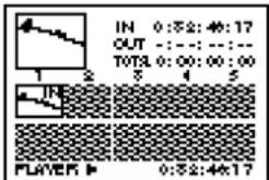
4 Designate the OUT point.
1 Locate the OUT point with the jog dial or shuttle ring. 2 Press MARK. The OUT point of the first event is stored. The total recording time is displayed. A few seconds later, "IN" flashes and you can designate the IN/OUT points for the next event.

5 To designate other events, repeat steps 3 and 4.
You can designate up to 10 events.
To check/change events
Press EVENT BACK or EVENT FWD to display each event in turn, and change the IN/OUT points according to the procedure in steps 3 and 4 if required.
6 Locate the point you want to start recording on this VCR.
1 Press RECORDER. 2 Press ▶ (PLAY), then search for the recording start point with the jog dial or shuttle ring. 3 Press START/PAUSE so that this VCR is set to recording pause.
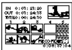
(continued)
Assemble editing (continued)
7 Press START / PAUSE.
The whole screen appears and assemble editing starts.
When editing ends, this VCR is set to recording pause and the screen in step 6 reappears.

To assemble edit more than 10 events
1 Press ASSEMBLE.
The assemble editing mode is canceled, and the IN/OUT points stored in memory are erased.
2 Repeat steps 2 to 7.
Note
- The recording does not stop the moment you press ■ to stop editing. The source picture may be recorded a little longer than you expected.
To stop assemble editing
To stop while editing, press START/PAUSE.
This VCR is set to recording pause, and you can check the events or change the recording starting point.
When you press START/PAUSE again, editing restarts from the first event.
To end assemble editing
Press ASSEMBLE.
All the IN/OUT points are erased.
Video insert editing
Notes
- Do not change the counter display during insert editing. Editing may not function accurately.
- Insert editing cannot be made on a blank portion of the tape. When a blank is detected, the VCR stops editing.
- If you record on the beginning part of the tape, or on the part just after the unrecorded portion, the first part of recording may be dropped.
You can replace the original picture with a scene from the source tape, while retaining the original sound.
Before you start editing, set up the system according to the instructions on pages 64 to 66.
For video insert editing, use the tape recorded by this VCR. If you want to edit the one recorded by other VCRs (including other DHR-1000s), first, you have to dub it to the tape on this VCR, then edit it. If you edit the tape recorded by the other VCRs, the sound quality may be reduced and the picture may be noisy.

1 Press COUNTER SELECT so that the tape counter appears.
2 Locate the end point (Ⓐ) of the scene to be recorded over.
1 Press RECORDER. 2 Press ▶ (PLAY), then locate the recording end point with the jog dial or shuttle ring. 3 Press COUNTER RESET.

(continued)
Video insert editing (continued)
Tips
• To execute V.O.S (video on sound) editing: 1 Record the audio. 2 Follow the insert editing procedure to record the video. - You can insert audio with the video by pressing the STEREO1 INSERT or/and STEREO 2 INSERT button(s) in step 4. - If you do not want to stop insert editing when the counter comes to "0H00M00S," change the counter display to the time code.
3 Locate the start point (®) of the scene to be recorded over.
Locate the beginning of the scene to be recorded over with the jog dial or shuttle ring.

4 Press VIDEO INSERT.
The indicator lights up.
5 Locate the playback start point (©) of the source tape.
1 Press PLAYER. 2 Press ▶ (PLAY), then locate the playback start point with the jog dial or shuttle ring. 3 Release the jog dial or the shuttle ring at the beginning of the source scene. The EDIT STANDBY indicator lights.

6 Press START/PAUSE.
The other VCR starts playback and this VCR starts recording. When the tape counter reaches "0H00M00S," the EDIT STANDBY indicator turns off and this VCR stops while the other VCR continues playing. To stop the other VCR, press PLAYER, then ■ (STOP).

To stop recording manually, press START/PAUSE.
Audio insert editing
Tips
- If you do not want to stop insert editing when the counter comes to "0H00M00S," change the counter display to the time code.
- You can insert both video and audio by pressing VIDEO INSERT in step 4.
Notes
- Do not change the counter display during insert editing. Editing may not function accurately.
- Insert editing cannot be made on a blank portion of the tape. When a blank is detected, the VCR stops editing.
- It may take up to 7 seconds for the sound to switch to the source tape. You cannot start recording until the sound switches.
- If you record on the beginning part of the tape, or on the part just after the unrecorded portion, the first part of recording may be dropped.
You can replace the original sound with sound from the source tape, while retaining the original picture.
Before you start editing, set up the system according to the instructions on pages 64 to 66.
For audio insert editing, use the tape recorded by this VCR. If you want to edit the one recorded by other VCRs (include other DHR-1000s), first, you have to dub it to the tape on this VCR, then edit it. If you edit the tape recorded by other VCRs, the sound quality may be reduced and the picture may be noisy.

1 Press COUNTER SELECT so that the tape counter appears.
2 Locate the end point of the scene to be recorded over.
1 Press RECORDER. 2 Press ▶ (PLAY), then locate the recording end point with the jog dial or shuttle ring. 3 Press COUNTER RESET.
3 Locate the start point of the scene to be recorded over.
Locate the beginning of the scene to be recorded over with the jog dial or shuttle ring.
4 Press STEREO 1 INSERT and/or STEREO 2 INSERT as follows:
When you record from DV input
Press both STEREO 1 INSERT and STEREO 2 INSERT.
You cannot replace stereo 1 track or stereo 2 track only.
When you record from LINE inputs
- To record in 16-bit audio, press both STEREO 1 INSERT and STEREO 2 INSERT.
- To record in 12-bit audio on the stereo 1 track, press STEREO 1 INSERT.
- To record in 12-bit audio on the stereo 2 track, press STEREO 2 INSERT.
For more information, refer to the chart on the next page.
A few seconds after you press the button, the sound switches to the source tape.
(continued)
Audio insert editing (continued)
Tip
- During recording, the indicators light according to the audio mode and the track being recorded. Example: when sound is recorded onto the stereo 1 track in 12-bit audio.

Note
- Depending on the VCR, when you playback mixed sound (stereo 1 track and stereo 2 track), the volume of stereo 1 track may change depending on whether sound is recorded on stereo 2 track or not.
5 Locate the playback start point of the source tape.
1 Press PLAYER. 2 Press ▶ (PLAY), then locate the playback start point with the jog dial or shuttle ring. 3 Release the jog dial or the shuttle ring at the beginning of the sound to be inserted. The EDIT STANDBY indicator lights.
6 Press START/PAUSE.
The other VCR starts playback and this VCR starts recording. When the tape counter reached "0H00M00S," the EDIT STANDBY indicator turns off and this VCR stops while the other VCR continues playing. To stop the other VCR, press PLAYER, then ■ (STOP).
To stop recording manually, press START/PAUSE.
How the audio recording mode selection affects editing results
When you record from DV input
This VCR automatically records in the same audio mode as the source tape, regardless of the LINE IN AUDIO setting in the ADVANCED OPTIONS menu. For this connection, press both the STEREO 1 INSERT and STEREO 2 INSERT buttons.
When you record from LINE inputs
The sound is recorded in the audio mode selected in LINE IN AUDIO in the ADVANCED OPTIONS menu. Normally, choose the original audio mode of the tape to be edited. Select the track to be replaced according to the audio recording mode.
| Original audio Menu Pressed Editing result mode of the choice button(s) edited tape | : Replaced section | ||
| 12-bit 12-bit STEREO 1 | Stereo1 | ||
| Stereo2 | |||
| STEREO 2 | Stereo1 | ||
| Stereo2 | |||
| STEREO 1 and STEREO 2 | Stereo1 | ||
| Stereo2 | |||
| NO AUDIO (Deleted) | |||
| 16-bit STEREO 1 and STEREO 2* | Stereo1 | ||
| Stereo2 | |||
| 16-bit 12-bit STEREO 1 and STEREO 2* | |||
Original audio Menu Pressed Editing result mode of the choice button(s) edited tape *Insert editing cannot be executed if you press only one button.
Connections
Note
- When you connect the other VCR using the DV jack, the data, index signals and the contents of the cassette memory are not transmitted.
Notes
- If you connect both LINE IN and LINE OUT jacks of this VCR to the other VCR, select the input correctly to prevent a humming noise.
- If you connect the cables to both the LINE-1 IN VIDEO and LINE-1 IN S-VIDEO jacks, the signal from the S-VIDEO jack is sent to the VCR and "S" lights in the display window. If you want to use the video signal from the VIDEO jack, set L1 IN VIDEO in the ADVANCED OPTIONS menu to "NORM" (page 54).
To a digital VCR with DV jack
With this connection, you can edit tapes with high-quality video and audio.
![graph TD A["Player"] --> B["Digital VCR (Camcorder)"] B --> C["DV INPUT"] C --> D["DV connecting cable (not supplied)"] D --> E["TV"] E --> F["Recorder"] F --> G["This VCR"] G --> H["DV INPUT + VIDEO UL3MC"] H --> I["Signal flow"]](/content/2026/06/1301747/images/2b404bc53cb32f22a1fe2cada9a5346c43b0e2369894aafadbc9f73f87c528da.jpg)
To a VCR without DV jack
If you do not need to change connections frequently, connect to the LINE-1 IN jacks on the rear of this VCR.
![graph TD A["Player"] --> B["The other VCR"] B --> C["TV"] C --> D["Recorder"] D --> E["This VCR"] E --> F["L-3AUDIO-R"] F --> G["+ VIDEO"] G --> H["Audio/video cable (supplied)"] H --> I["S-video cable (supplied, when the other VCR has a S VIDEO OUT jack)"] I --> J["Audio/video cable (supplied)"] J…](/content/2026/06/1301747/images/a984c800cad140f79a3e1e8815caf41c02d5dae823e3dadbbe939e9636bf5df4.jpg)
Note
- Distorted signals (e.g. when played back at a speed other than normal) will not be recorded properly.
(continued)
Connections (continued)
Tip
• To connect a monaural VCR, use the LINE-2 IN jack and connect to the L jack (white) (leave the red audio plug unconnected). The monaural audio from the L jack will be recorded on both left and right tracks.
Notes
- If you connect the cables to both the LINE-2 IN VIDEO and LINE-2 IN S-VIDEO jacks, the signal from the S-VIDEO jack is sent to the VCR and "S" lights in the display window. If you want to use the video signal from the VIDEO jack, set L2 IN VIDEO in the ADVANCED OPTIONS menu to "NORM" (page 54).
- Distorted signals (e.g. when played back at a speed other than normal) will not be recorded properly.
Tips
• Editing is not possible with a tape that is copyright protected. - When you finish editing, set EDIT switch to "OFF."
Notes
- The REC LEVEL and REC BALANCE controls do not function on a source input through the DV jack.
- With the DV connection, the playback VCR's AUDIO MONITOR and AUDIO MIX BALANCE do not function on the source audio output through the DV jack.
To a camcorder without DV jack
The LINE-2 IN jacks on the front of the VCR is convenient if you connect or disconnect a camcorder frequently.
![graph TD A["Player"] --> B["Camcorder"] B --> C["Audio/video cable (supplied)"] C --> D["Recorder"] D --> E["This VCR"] B --> F["Line OUT"] D --> G["Line 2IN"] C --> H["S-video cable (supplied, when the other VCR has a S VIDEO OUT jack)"]](/content/2026/06/1301747/images/c2daf9edc4caf39f2ee7f9d7f7acb26e559181d1afdb8a07e3f5a6ac0c005303.jpg)
: Signal flow
Preparation
On the player
- Insert a source tape.
- If the player VCR has an EDIT switch, set it to ON.
- Turn off the on-screen display.
On the recorder (this VCR)
- Insert a tape.
- Press INPUT SELECT so that the jack to which the player is connected appears in the display window: "L1," "L2," or "DV"
- When you connect to the LINE 1/2 IN jacks, adjust the recording level and balance with the REC LEVEL and REC BALANCE controls. Play back the source, then adjust the controls so that the red indicators of the level meter do not light up. Select the balance according to your need (normally, set it to the center).
Copying a tape
You can copy a whole tape to the other tape.
Before editing, set up the system according to the instructions on pages 77 to 78.

1 Search for the points where you want to start playing or recording, and set both VCRs to stop.
2 Press ● REC on this VCR while holding down ■ PAUSE.
This VCR is set to recording pause.
3 Search for the point to start playback on the other VCR, and set it to playback pause.
For best results, pause the tape a few seconds before the beginning of the scene.
4 Press the pause button on the other VCR to start playback. At the beginning of the scene you want to record, press II PAUSE on this VCR to start recording.
Note
- If you start recording as soon as playback starts, the first few seconds of the picture and/or sound may become distorted.
To stop copying
Press ■ STOP on this VCR and the other VCR.
Cutting out unwanted scenes
With this function, you can cut out unwanted scenes while making a copy.
Before you start editing, set up the system according to the instructions on pages 77 to 78.


1 Search for the points where you want to start playing or recording, and set both VCRs to stop.
2 Press ● REC on this VCR while holding down Ⅱ PAUSE.
This VCR is set to recording pause.
3 Search for the point to start playback on the other VCR, and set it to playback pause.
For best results, pause the tape a few seconds before the beginning of the scene.
4 Press the pause button on the other VCR to start playback. At the beginning of the scene you want to record, press II PAUSE on this VCR to start recording.
Note
- If you start recording as soon as playback starts, the first few seconds of the picture and/or sound may become distorted.
Notes
- If you press ■ STOP to stop editing, the source picture may be recorded after it stops.
- If you record on the beginning part of the tape, or on the part just after an unrecorded portion, the first part of the recording may be dropped.
- When you record on a new or fully rewound tape, do a trial recording for about 15 seconds, then start the actual recording. If you start the actual recording from the beginning of the tape, the first part may not be recorded when you play back the tape on another VCR.
5 Press II PAUSE on this VCR just before the beginning of the unwanted scene (A). This VCR is set to recording pause.
6 Search for the point (®) to resume recording on the other VCR. After searching, set the other VCR to playback pause.
7 Press the pause button on the other VCR to start playback, then press III PAUSE on this VCR to resume recording.
8 To cut out other scenes, repeat steps 5 to 7.
To finish editing
Press ■ STOP on both VCRs.
Video insert editing
Notes
- Do not change the counter display during insert editing. Editing may not function accurately.
- Insert editing cannot be made on a blank portion of the tape. When a blank is detected, the VCR stops editing.
- If you record on the beginning part of the tape, or on the part just after the unrecorded portion, the first part of recording may be dropped.
You can replace the original picture with a scene from the source tape, while retaining the original sound.
Before you start editing, set up the system according to the instructions on pages 77 to 78.
For video insert editing, use the tape recorded by this VCR. If you want to edit the one recorded by other VCRs (including other DHR-1000s), first, you have to dub it to the tape on this VCR, then edit it. If you edit the tape recorded by the other VCRs, the sound quality may be reduced and the picture may be noisy.


1 Press COUNTER SELECT so that the tape counter appears.
2 Locate the end point (A) of the scene to be recorded over.
1 Press ▷ PLAY, then locate the recording end point with the jog dial or shuttle ring. 2 Press COUNTER RESET.

3 Locate the start point (⑧) of the scene to be recorded over.
Locate the beginning of the scene to be recorded over with the jog dial or shuttle ring.

4 Press VIDEO INSERT.
The indicator lights up.
Tips
• To execute V.O.S (video on sound) editing: 1 Record the audio. 2 Follow the insert editing procedure to record the video. - You can insert audio with the video by pressing the STEREO 1 INSERT or/and STEREO 2 INSERT button(s) in step 4. - If you do not want to stop insert editing when the counter comes to "0H00M00S," change the counter display to the time code.
5 Locate the playback start point of the source tape (©), then set the VCR to playback pause.
For best results, pause the tape a few seconds before the beginning of the scene.

6 Press the pause button on the other VCR to start playback. At the beginning of the scene you want to replace, press III PAUSE on this VCR to start recording.
Video insert editing starts. When the tape counter reaches "0H00M00S," recording stops automatically.
7 Press ■ STOP on the other VCR.
Audio insert editing
Tips
- If you do not want to stop insert editing when the counter comes to "0H00M00S," change the counter display to the time code.
- You can insert both video and audio by pressing VIDEO INSERT in step 4.
Notes
- Do not change the counter display during insert editing. Editing may not function accurately.
- Insert editing cannot be made on a blank portion of the tape. When a blank is detected, the VCR stops editing.
- It may take up to 7 seconds for the sound to switch to the source tape. You cannot start recording until the sound switches.
- If you record on the beginning part of the tape, or on the part just after the unrecorded portion, the first part of recording may be dropped.
You can replace the original sound with sound from the source tape, while retaining the original picture.
Before you start editing, set up the system according to the instructions on pages 77 to 78.
For audio insert editing, use the tape recorded by this VCR. If you want to edit the one recorded by other VCRs (include other DHR-1000s), first, you have to dub it to the tape on this VCR, then edit it. If you edit the tape recorded by the other VCRs, the sound quality may be reduced and the picture may be noisy.

1 Press COUNTER SELECT so that the tape counter appears.
2 Locate the end point of the scene to be recorded over.
1 Press ▷ PLAY, then locate the recording end point with the jog dial or shuttle ring. 2 Press COUNTER RESET.
3 Locate the start point of the scene to be recorded over.
Locate the beginning of the scene to be recorded over with the jog dial or shuttle ring.
4 Press STEREO 1 INSERT and/or STEREO 2 INSERT as follows:
When you record from DV input
Press both STEREO 1 INSERT and STEREO 2 INSERT. You cannot replace stereo 1 track or stereo 2 track only.
When you record from LINE inputs
- To record in 16-bit audio, press both STEREO 1 INSERT and STEREO 2 INSERT.
- To record in 12-bit audio on the stereo 1 track, press STEREO 1 INSERT.
- To record in 12-bit audio on the stereo 2 track, press STEREO 2 INSERT. For more information, refer to the chart on the next page.
A few seconds after you press the button the sound switches to the source tape.
5 Locate the playback start point of the source tape (©), then set the VCR to playback pause.
For best results, pause the tape a few seconds before the beginning of the scene.
6 Press the pause button on the other VCR to start playback. At the beginning of the scene you want to replace, press III PAUSE on this VCR to start recording.
Audio insert editing starts.
When the tape counter reaches "0H00M00S", the recording tape stops automatically.
7 Press ■ STOP on the other VCR.
How the audio recording mode selection affects editing results
When you record from DV input
This VCR automatically records in the same audio mode as the source tape, regardless of the LINE IN AUDIO setting in the ADVANCED OPTIONS menu. For this connection, press both the STEREO 1 INSERT and STEREO 2 INSERT buttons.
When you record from LINE inputs
The sound is recorded in the audio mode selected in LINE IN AUDIO in the ADVANCED OPTIONS menu. Normally, choose the original audio mode of the tape to be edited. Select the track to be replaced according to the audio recording mode.
Tip
- During recording, the indicators light according to the audio mode and the track being recorded. Example: when sound is recorded onto the stereo 1 track in 12-bit audio.

Note
- Depending on the VCR, when you playback mixed sound (stereo 1 track and stereo 2 track), the volume of stereo 1 track may change depending on whether sound is recorded on stereo 2 track or not.
| Original audio Menu Pressed Editing result mode of the choice button(s) edited tape | : Replaced section | ||
| 12-bit 12-bit STEREO 1 | Stereo1 | ||
| Stereo2 | |||
| STEREO 2 | Stereo1 | ||
| Stereo2 | |||
| STEREO 1 and STEREO 2 | Stereo1 | ||
| Stereo2 | |||
| NO AUDIO (Deleted) | |||
| 16-bit STEREO 1 and STEREO 2* | Stereo1 | ||
| Stereo2 | |||
| 16-bit 12-bit STEREO 1 and STEREO 2* | |||
| 16-bit STEREO 1 and STEREO 2* | |||
*Insert editing cannot be executed if you press only one button.
Audio dubbing
Notes
- You cannot use the audio dubbing feature on a tape recorded in 16-bit audio mode.
- When a microphone and a source to LINE-2 IN are both connected, the mixed sound of the two sources is recorded. The audio from the microphone is recorded in monaural.
You can add music or commentary to a tape recorded in 12-bit audio mode.
Music or narration is recorded on the stereo 2 track, while the original sound on stereo 1 track remains.
For audio dubbing, use the tape recorded by this VCR. If you want to edit the one recorded by other VCRs (including other DHR-1000s), first, you have to dub it to the tape on this VCR, then edit it. If you edit the tape recorded by the other VCRs, the sound quality may be reduced and the picture may be noisy.
Connection![graph TD A["Microphone"] -->|Audio cable (not supplied)| B["Line OUT"] B --> C["Audio equipment"] C --> D["This VCR"] D --> E["Line 2R"] E --> F["Audio R"] F --> G["DUI/OUT"] G --> H["MIO PHINER PHINELD"] H --> I["Signal flow"]](/content/2026/06/1301747/images/96ef14e72ae5bcec40ebdec177a1d5d810a5c8c1bd7e8b40102006125dd75f8e.jpg)
Preparation
- Insert a prerecorded tape into this VCR.
- Press INPUT SELECT so that "L2" appears in the display window.
- Set the audio recording mode to 12-bit.
1 Press MENU.
The MENU screen appears on the TV screen.
2 Select ADVANCED OPTIONS by pressing the CURSOR (↑/↓) buttons and press EXECUTE. 3 Select LINE IN AUDIO by pressing the CURSOR (↑/↓) buttons. 4 Select "12" by pressing CURSOR (←/→) buttons.
Adjust the recording level and balance with the REC LEVEL and REC BALANCE controls.
While playing the source or speaking into the microphone, adjust the controls so that the red indicators of the level meter do not light up.
Select the balance according to your need (normally, set it to the center).
Operation
Tips
- If you do not want to stop insert editing when the counter comes to "0H00M00S," change the counter display to the time code.
- For fade-in operation, turn the REC LEVEL control clockwise from the zero point.
- For fade-out operation, turn the REC LEVEL control counterclockwise to the zero point.
Notes
- Do not change the counter display during insert editing. Editing may not function accurately. • Audio dubbing cannot be made on a blank portion of the tape. When a blank is detected, the VCR stops editing.
- It may take up to 7 seconds for the sound to switch to the source tape. You cannot start recording until the sound switches.
- If you record on the beginning part of the tape, or on the part just after the unrecorded portion, the first part of recording may be dropped.
1 Press COUNTER SELECT so that the tape counter appears. 2 Locate the end point of the scene to be recorded over.
1 Press ▷ PLAY, then locate the recording end point with the jog dial or shuttle ring. 2 Press COUNTER RESET. 3 Press ■ PAUSE.
3 Locate the start point of the scene to be recorded over.
Locate the jog dial or shuttle ring to left, and release it when the desired scene appears on the TV screen.
4 Press AUDIO DUB. 5 Press II PAUSE on this VCR and start playing the audio source or speaking into the microphone.
The source audio is recorded on the stereo 2 track of the tape, while the picture appears on the TV screen (the audio on the stereo 1 track is not played).
When the tape counter reaches "0H00M00S," recording stops automatically.
6 Stop playback of the audio equipment.
Listening to the inserted/dubbed sound
1 Start playback of the inserted/dubbed tape.
2 Set the AUDIO MONITOR selector to the track you want to hear:
- For stereo 1 track, set to STEREO 1.
- For stereo 2 track, set to STEREO 2.
- For both stereo 1 and stereo 2 tracks, set to MIX.
AUDIO MONITOR

STEREO 1 MIX STEREO 2

When you select "MIX," you can adjust the audio balance between the stereo 1 and stereo 2 tracks with the AUDIO MIX BALANCE control.
The PCM MODE indicators light according to the contents of the tape.
Lights while playing back a tape recorded in 16-bit mode.

Connecting a titler or editing controller
Connecting a titler
Notes
- You cannot make the DV connection when using the titler. To use a digital SEG, connect it with the LINE jacks. You cannot make the DV connection.
![graph TD A["Audio/video cable"] --> B["Titler"] B --> C["To LANC jack (When the other VCR has a LANC jack)"] C --> D["Another VCR"] D --> E["TV"] E --> F["This VCR"] F --> G["S-video cable"] G --> H["Audio/video cable"] H --> I["To LINE output"] I --> J["Audio/video cable"] style A fill:#f9f,stroke:…](/content/2026/06/1301747/images/a55c5455bfe01f540fca3f1a04334d95619e28069a260c368419ac15bc87ee4c.jpg)
(continued)
Connecting a titler or editing controller (continued)
Notes
- When you connect an editing controller with the DV connection, you cannot connect a titler or a digital SEG in addition.
- If you use an RM-E1000 as the editing controller, and this VCR is set up as the recording machine without the DV connection, occasionally, editing may start about one second later than the IN point. In this case, try changing the player search mode (FF/REW or CUE/REV) on the editing controller.
- Connections differ depending on the controller model. Refer to the manual of the connected equipment. To use a controller equipped with a titler function, you need to make audio/video connections in addition to the connection shown on the right. While recording, press INPUT SELECT on this VCR to select the video that you want to record.
Connecting an editing controller
![graph TD A["TV"] --> B["This VCR"] B --> C["DV INPUT+VIDEO GLAHC"] C --> D["DV connecting cable"] D --> E["Editing controller"] E --> F["To LANC jack"] F --> G["LANC cable"] G --> H["Another VCR"] H --> I["Other VCRs"] style A fill:#f9f,stroke:#333 style B fill:#ccf,stroke:#333 style C fill:#cfc,str…](/content/2026/06/1301747/images/2c53013b8a9c30d284f2effba2fc60057e830a9ede6f2651113fd962bd0179c5.jpg)
: Signal flow
Preparation
- When you make the LANC connection, follow "Connections" on page 64.
- When you don't make the LANC connection, follow "Connections" on page 77.
For further instructions, refer to the manual of the connected equipment.
Connecting a capture board or video printer
You can output a still picture to your computer using a capture board (optional) and print out the picture using a video printer (optional).
Connecting the DVBK-1000 capture board
With this connection, you can output a still picture to your computer.
![graph TD A["DVBK-1000 (for IBM compatible computer)"] --> B["TV"] A --> C["This VCR"] A --> D["DV connecting cable"] D --> E["LANC cable"] F["TV"] --> G["This VCR"] H["DV INPUT & VIDEO & PLC"] --> I["DV connecting cable"] style A fill:#f9f,stroke:#333 style F fill:#ccf,stroke:#333 style H fill:#cfc,…](/content/2026/06/1301747/images/41db1c086f8867dc1bb3009a5e3213860a986be547fd937361d9b432aedcd31c.jpg)
For further instructions, refer to the manual of the connected equipment.
Note
- If your video printer does not have an S-VIDEO input jack, connect to the video input jack on your video printer with a video cable.
- If your video printer has a LANC jack, connect the LANC jacks on your VCR and video printer with the LANC cable and set LANC MODE in the ADVANCED OPTIONS menu on your VCR to "S." You can print out with the PRINT button on the remote commander of this VCR.
- For further instructions, refer to the manual of the connected equipment.
Connecting a video printer
With this connection, you can print out a still picture.
![graph TD A["Video printer"] --> B["TV"] B --> C["This VCR"] D["S-video cable"] --> E["L-VIDEO-R"] E --> F["+ VIDEO"] F --> G["+ VIDEO"] G --> H["+ VIDEO"] H --> I["+ VIDEO"] I --> J["+ VIDEO"] J --> K["+ VIDEO"] K --> L["+ VIDEO"] L --> M["+ VIDEO"] M --> N["+ VIDEO"] N --> O["+ VIDEO"] O --> P["+ V…](/content/2026/06/1301747/images/9bedc790d06300fd6a0c89d62862a98c9088300abb57408d4b956bc664cb8df3.jpg)
: Signal flow
Additional information General setup information


Setting the RF unit
When connecting the VCR to the TV using only the antenna cable, you must set the RF UNIT switch on the rear of the VCR so that the TV can receive the correct signal from the VCR.
1 Set the RF UNIT switch on the rear of the VCR to CH3 or CH4, whichever channel is not used in your area.
If both are used, set the switch to either channel.
2 Press POWER to turn on the VCR. 3 Press TV/VTR to turn on the VTR indicator in the VCR's display window. 4 Press CH +/- to display a channel number in the display window. Select an active channel number in your area. 5 Turn on your TV and set it to the channel you selected in step 1 (channel 3 or 4).
The selected TV channel broadcast appears on the TV screen. If the channels change when you press CH +/- on the VCR, you have made the correct setting.
Whenever you use the VCR, set the TV to the channel selected in step 1.
Attaching the external antenna connector
When using a 300-ohm twin lead cable for VHF/UHF antenna, use the EAC-32 antenna connector (not supplied) to connect the antenna to the VCR
1 Loosen the screws on the antenna connector. 2 Wind the twin leads around the screws on the antenna connector. 3 Retighten the screws.
Attaching a UHF/VHF band mixer
When using both 75-ohm coaxial cable and 300-ohm twin lead cable for VHF/UHF antenna, use the EAC-66 UHF/VHF band separator/mixer (not supplied) to connect the antenna to the VCR
1 Loosen the screws on the mixer. 2 Wind the twin leads around the screws on the mixer. 3 Retighten the screws. 4 Connect the 75-ohm coaxial cable to the mixer.
Precautions
Notes on the video cassette recorder
Do not install the unit in a place subject to direct sunlight or heat sources
If you do, its cabinet, mechanical parts, etc., may be damaged.
Do not install the unit in an extremely hot place.
If the unit is left in a car parked with its windows closed (especially in summer), its cabinet may be damaged or it may not work correctly.
If the unit is brought directly from a cold to a warm location.
Moisture may condense inside the unit and cause damage to the video head and tape. If you use the unit in a place subject to direct cold currents from an air conditioner, moisture may also condense inside the unit.
Do not place heavy objects on the unit.
The cabinet may be damaged, or the VCR may not work correctly.
Do not handle the recorder roughly.
Avoid rough handling or mechanical shock.
To avoid damaging the cabinet finish.
Plastic is often used for the surface finishing of the recorder. Do not spray a volatile solvent such as an insecticide toward the cabinet or place rubber or vinyl products on the cabinet for a long time. If you do, the finish of the cabinet may be damaged or the coating may come off.
Do not clean the cabinet with thinner or benzine.
The cabinet may be damaged or its coating may come off. When you use a chemical-impregnated cloth, use it according to its directions.
Clean the cabinet with a soft dry cloth.
When the cabinet is very dirty, clean it with a soft dry cloth lightly moistened with a mild detergent solution and finish it with a dry cloth.
Do not put magnetic objects close to the unit
Magnetic fields may damage the recording.
Checking the video heads every 1000 hours
A VCR is a high-precision piece of equipment that records and plays back the picture on a magnetic tape. In particular, the video head and other mechanical parts become dirty or worn. To maintain a clean picture, we recommend maintenance every 1000 hours, though the using condition may differ depending on temperature, humidity, dust, etc.
(continued)
Precautions (continued)
Cleaning of the video heads
If the video heads are contaminated, the pictures cannot be recorded properly or the playback pictures become noisy. If the following phenomena occur, use the cleaning cassette (supplied) or Sony video head cleaning cassette (not supplied) to clean the heads.
- Square-shaped noise appears on the playback picture.
- A part of the playback picture does not move.
- The playback picture does not appear on the screen.
Symptoms caused by contaminated video heads
If these pictures appear on the screen, use the cleaning cassette.
After prolonged use, the video heads may become worn out. If optimum picture quality is not restored even after you have cleaned the video heads with the cleaning cassette, the video heads may have worn out. In that case, you have to replace the video heads with new ones. Please consult your Sony dealer.
Notes on the video cassettes
Usable cassettes
We recommend using Standard-DV/Mini-DV cassettes to get the most out of the high reliability of the DV format.
Cleaning the terminal
If the terminal of the DV or Mini-DV cassette gets dirty, or dust sticks to the terminal, the VCR may not work correctly.
Clean the connector with the swab once every ten times you eject a cassette.
Terminal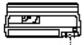
When affixing a label on the cassette
Be sure to affix a label only on the location as illustrated below so as not to cause malfunction of the VCR.
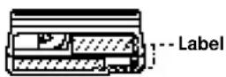
After using a cassette
After use, please be sure to rewind the tape completely (to prevent picture and sound distortion). Return it to its case and store in an upright position.
About moisture condensation
If the unit or tape is brought directly from a cold to a warm location, moisture may condense inside or outside the unit or tape. If you use the tape or video heads in this condition, the tape may adhere to the head drum, and the video heads or the tape may be damaged, or malfunction may occur.
Moisture condensation is likely to occur under the following conditions:
- The unit is brought from the cold outdoors to a warm indoor location.
- The unit is brought from the air-conditioned indoors to the hot outdoors.
- The unit is used in a place subject to cold currents from an air conditioner.
When bringing the unit from a cold place to a warm place or vice versa, put it in a plastic bag and seal the bag tightly. After bringing it into the new place, leave the bag on for about an hour, and remove the bag when the air temperature inside it has reached the temperature surrounding it.
If moisture condensation occurred
You cannot operate the unit except to press ▲ EJECT. If you insert a cassette, it is ejected automatically. If this occurs, turn on the power, wait about an hour for the moisture to evaporate.
Troubleshooting
If you have any questions or problems not covered below, please consult your nearest Sony dealer.
| Symptom | Remedy | |
| Power | The POWER switch does not function. | Connect the mains lead securely. |
| The power is turned on but the VCR does not operate. | Turn off the power and disconnect the mains lead. After about one minute, connect the mains lead and turn on the VCR.Press the CL button. Reset the clock, timer, and menu settings.Moisture condensation has occurred. With the power left on, leave the VCR to dry for one to two hours. | |
| Clock | The clock has stopped and “-:- -” lights in the display window. | The clock stops if the VCR is disconnected from the wall outlet for more than 30 minutes. Reset the clock (and timer). |
| Playback | The playback picture does not appear on the TV screen. | Make sure the TV is set to the channel for the VCR. If you are using a A/V hook up, set it to video input.The menu appears on the screen. Press MENU to make it disappear.No recording on the tape.The video heads are dirty. Clean the video heads. |
| With DV connection, the playback picture of the other VCR does not appear on the monitor screen. | Disconnect the DV cable and connect it again. INPUT SELECT is set to “L1” or “L2.” Select “DV.”The other VCR is not playing back. | |
| A mosaic pattern appears in the playback picture or a part of the picture does not appear. | The video heads are dirty (see below). Clean the video heads using the Sony video head cleaning cassette. Do not use a commercially available wet-type cleaning cassette, as it may damage the video heads.Symptoms caused by contaminated video heads    initial terminalThe video heads may have to be replaced. Consult your local Sony dealer for more information.The tape is defective. Use a new tape.Use Sony brand DV tapes. initial terminalThe video heads may have to be replaced. Consult your local Sony dealer for more information.The tape is defective. Use a new tape.Use Sony brand DV tapes. | |
| The pictures input from the LINE-1/LINE-2 IN jacks or DV IN jack do not appear on the monitor screen. | Press INPUT SELECT to select the correct input.If you connect cables to both audio/video jacks and S-VIDEO jack of LINE-1 IN/LINE-2 IN, signals from the S-VIDEO jack take priority. (“S” lights in the display window.) To select signals from the LINE-1 IN video jack, set “L1 IN VIDEO” in the ADVANCED OPTIONS menu to “NORM.”To select signals from the LINE-2 IN jacks, disconnect the cable from the jack you do not use. | |
| The picture has no sound. | When you play a tape recorded in 12-bit mode, set the AUDIO MONITOR selector to the track when the sound is recorded.The tape is defective. Use a new tape. | |
| Playback (continued) | Mixed sound is heard. | ·When you play a bilingual tape, select the sound you want by pressing AUDIO MONITOR.·When you play a tape recorded in 12-bit mode, set the AUDIO MONITOR selector to the track when the sound is recorded. |
| Though the tape is recorded in stereo, playback sound is monaural. | ·Audio from one track only is selected. Press AU MONITOR MAIN/SUB. | |
| The playback sound is skipped. | ·The tape is defective. Use a new tape. | |
| Recording | A TV program does not appear. | ·Make sure the TV is set to the channel for the VCR. If you are using a A/V hookup, set it to video input.·Make sure the cable box and/or DSS receiver is/are turned on.·Replace the Cable mouse. |
| TV reception is poor. | ·Adjust the TV antenna. | |
| The tape ejects when you press ●REC. | ·Check that the protect tab is set to the recording enable position. | |
| Nothing happens when you press ●REC. | ·Make sure the tape has been rewound to the beginning.·Select the correct source with the INPUT SELECT or PROG+/-button(s). | |
| Timer recording | The timer does not operate. | ·Check that the clock is set.·Make sure a tape has been inserted.·Check that the protect tab is set to the recording enable position.·Make sure the tape has been rewound to the beginning.·Make sure your timer settings have not already passed the current time.·Check that the decoder is turned on.·The clock stops if the power to the VCR is interrupted for more than 30 minutes. Reset the clock and timer.·Make sure the cable box or/and DSS receiver is/are turned on.·Replace the Cable mouse. |
| Editing | The picture of the other VCR does not appear. | ·Make sure the connections between VCRs are firm.·Select the correct input with the INPUT SELECT or CH +/-button(s). |
| The tape ejects when you press START/PAUSE. | ·Check that the protect tab is set to the recording enable position.·You cannot copy any software having copyright protection signals. | |
| Time codes are not sequential in the display. | ·In the DF (Drop Frame) mode, the time code may skip from 29-frame to 02-frame.·There is an unrecorded portion (blank) between recorded portions. are not recorded in sequence.·The video heads are dirty. Clean the video heads using the video head cleaning cassette.·Time code display may stop when you fast-forward or rewind the tape. |
(continued)
Troubleshooting (continued)
| Symptom | Remedy | |
| Editing (continued) | Assemble editing does not operate. | ·The counter is set to the remaining time display. Press COUNTER SELECT so that the tape counter or time code appears in the display window. |
| The VCR stops during insert editing. | ·The VCR stops automatically when the tape counter reaches 0:00:00. Set the editing end point to 0:00:00. ·There is an unrecorded portion on the source tape. ·The portion to be replaced is recorded in both 12-bit and 16-bit audio modes. | |
| The picture from the input jack is distorted. | ·The signal played back by the DVD player or VCR, or received by the DSS receiver includes a copyright protection signal. Disconnect the device and connect it to the TV directly. | |
| Remote commander | The remote commander does not function. | ·The batteries are weak. Replace all the batteries with new ones. ·No batteries are inserted in the battery compartment. ·Turn on the power of the main unit. ·Make sure you are pointing the remote commander at the remote sensor on the VCR. ·Select the same command mode on the VCR and the remote commander. |
| When operating this VCR with the supplied remote commander, other Sony video equipment as well as this VCR start operation. | ·COMMAND MODE selectors of this VCR and other Sony video equipment are set to the same number. Change the setting of the COMMAND MODE selector on this VCR. | |
| Others | A tape cannot be inserted. | ·Check that a tape isn't already in the tape compartment. |
| The tape is ejected. | ·Moisture condensation has occurred. With the power left on, leave the VCR to dry for one to two hours. | |
| The tape counter stops. | ·The counter display stops when an unrecorded portion is displayed. ·The counter display may stop when you fast-forward or rewind the tape. | |
| “- : - -” flashes in the display window of the main unit. | ·Set the clock on the menu screen. | |
| The Index Titler or Cassette Label recorded by a camcorder does not appears on the TV screen. | ·The Index Titler or Cassette Label function does not work with this VCR. |
Specifications
System
Recording format
DV standard (consumer Digital VCR format, SD specifications)
Video signal
EIA STANDARD, NTSC color system
Usable cassettes
DV cassettes and Mini-DV cassettes
Recording time
180 minutes (when using the DV-180 cassette)
Fast-forward and rewind time
Approx. 1.5 min. (with DV-180 tape)
Video
Quantization word length
8-bit
Sampling frequency
13.5 MHz
Horizontal resolution
More than 500 lines
Audio
Quantization word length
16-bit linear or 12-bit non-linear
Sampling frequency
32 kHz 12-bit (recording mode)
48 kHz 16-bit (recording mode)
44.1 kHz 16-bit (playback only)
32 kHz 16-bit (playback only)
Tuner section
Tuning system
PLL synthesizer system
Audio tuning system
Inter-carrier system
Channel coverage
VHF 2 to 13
UHF 14 to 69
CATV A-8 to A-1, A to W, W+1 to
W+84
Antenna
75-ohm antenna terminal for VHF/UHF
Timer section
Clock
Quartz locked
Timer indication
24-hour cycle
Timer setting
Max. 8 programs per month
Power back-up
Built-in self-charging capacitor
Back-up duration: up to 30 minutes
(continued)
Specifications (continued)
Inputs and outputs
Antenna
75-ohm antenna terminal for VHF/UHF
Mini jack (plug in power) (1)
CONTROL S IN
Mini jack (1)
DV IN/OUT
DV type 4-pin jack (1)
LINE IN 1 and 2
VIDEO IN, pin jack (1 each) Input signal: 1 Vp-p, 75 ohms, unbalanced, sync negative
AUDIO IN, pin jack (2 each) Input level: 2 Vrms (full bits) Input impedance: more than 47 kohms
S-VIDEO IN, Mini DIN 4-pin connector (1 each)
Y (luminance signal): 1 Vp-p, 75 ohms, unbalanced, sync negative C (colour signal): 0.286 Vp-p, 75 ohms, unbalanced
LINE OUT 1 and 2
VIDEO OUT, pin jack (1 each) Output signal: 1 Vp-p, 75 ohms, unbalanced, sync negative
AUDIO OUT, pin jack (2 each) Standard output: 2 Vrms (full bits) Output impedance: less than 10 kohms
S-VIDEO OUT, Mini DIN 4-pin connector (1 each)
Y (luminance signal): 1 Vp-p, 75 ohms, unbalanced, sync negative C (colour signal): 0.286 Vp-p, 75 ohms, unbalanced
Headphone jack
Mini jack (monaural, 1)
General
Power requirements
120 V AC, 60 Hz
Power consumption
43 W
Operating temperature
5°C to 40°C
Storage temperature
-20°C to 60°C
Dimensions
Approx. 430 · 129 · 376 mm (17 · 5 1/8 · 13 3/4 inches) (w/h/d, including projecting parts and controls)
Mass
Approx. 10 kg (22 lbs 70 z)
Supplied accessories
AC power cord (1) Audio/video cable (1)
Cable Mouse (1)
Cleaning cassette (1) Control S cable (1)
LANC cable (1)
Remote commander (1)
S-video cable (1)
Size AA(R6) batteries (2)
75-ohm coaxial cable (1)
Design and specifications are subject to change without notice.
Index to parts and controls
Refer to the pages indicated in ( ) for details.
Front panel

16BIT/12BIT indicator (61) 2 Cassette panel (38) 3 ▲ EJECT button (38) 4 See section A below. 5 OPERATION PANEL OPEN/CLOSE button (102) 6 Audio indicators
7 Display window (104) 8 VTR indicator (39) 9 See section B below. 10 Remote sensor 11 Power switch
A![graph TD A["1"] --> B["●"] C["2"] --> D["●"] E["3"] --> F["○"] G["Box"] --> H[" "] I["4"] --> J["●"] style A fill:#f9f,stroke:#333 style C fill:#f9f,stroke:#333 style E fill:#f9f,stroke:#333 style G fill:#ccf,stroke:#333 style I fill:#ccf,stroke:#333 style J fill:#ccf,stroke:#333](/content/2026/06/1301747/images/916563a742152009587b8954c297649a20ea6d59a7fe6d0b170ec105178b02d3.jpg)
1 MIC (microphone) jack (86) 2 PHONES jack 3 CL button (92) 4 PHONE LEVEL control
B![graph TD A["1"] --> B["3"] B --> C["4"] B --> D["3"] B --> E["2"]](/content/2026/06/1301747/images/7a12f10b6e8e508241cf07e2fbb1aefa06ed3604f5e90b891403e63ae2c47e15.jpg)
1 LINE-2 IN jacks (65, 78) 2 LANC jack (62, 64) 3 LINE-2 IN S-VIDEO jack (65, 78) 4 DV IN/OUT jack (64, 77)
(continued)
Index to parts and controls (continued)
Operation panel

1 Menu buttons (MENU, CURSOR and EXECUTE buttons) (27, 54) 2 See section C on the next page. 3 PCM MODE indicators (88) 4 See section D on the next page. 5 MARK button (70) 6 ▶ (play) button (66) 7 ■ (stop) button (66) 8 II (pause) button (66) 9 PLAYER button (66) 10 RECORDER button (66) 11 Shuttle ring (66) 12 Jog dial (66)
13 ● REC button (39) 14 II PAUSE button (38) 15 CHANNEL +/- buttons (39) 16 ▶▶FF button (38) 17 ▷ PLAY button (38) 18 ◀◀ REW button (38) 19 ■ STOP button (38) 20 EASY SET UP button (15) 21 QUICK TIMER button (48) 22 See section E on the next page. 23 COMMAND MODE switch
(continued)
C![graph TD A["1"] --> B["2"] C["1"] --> D["3"] E["4"] --> F["4"]](/content/2026/06/1301747/images/d8d3348365ea3eaf497ec4fba3fcbc0411ad8ff40dd84aef410ff893f164df97.jpg)
1 AUDIO MONITOR selector (63, 88)
2 AUDIO MIX BALANCE control (63, 88)
3 REC BALANCE control (66, 86)
4 REC LEVEL control (66, 86)
D![graph TD A["1"] --> B["2"] B --> C["3"] C --> D["4"] D --> E["5"] E --> F["6"] F --> G["7"] G --> H["8"] H --> I["9"] I --> J["10"] J --> K["11"] K --> L["12"] L --> M["13"] M --> N["14"] N --> O["15"] O --> P["16"] P --> Q["17"] Q --> R["18"] R --> S["19"] S --> T["20"]](/content/2026/06/1301747/images/85d3f6bd88dbbceaebb8f9c657d6539fdb5d25e12abd6c2cc69b980626840f1e.jpg)
1 VIDEO INSERT button (74, 82)
2 STEREO 1 INSERT button (75, 84)
3 STEREO 2 INSERT/AUDIO DUB button (75, 84, 87)
4 ASSEMBLE button (71)
5 EVENT BACK/FWD buttons (71)
6 START/PAUSE button (67)
7 EDIT STANDBY button (68)
8 DUPLICATE ENTIRE TAPE button (67)
E![graph TD A["1"] --> B["2"] C["3"] --> D["4"] E["5"] --> F["6"] G["7"] --> H["8"] I["0"] --> J["1"] K["9"] --> L["1"] M["4"] -.-> N["5"] O["7"] -.-> P["8"] Q["0"] -.-> R["1"]](/content/2026/06/1301747/images/0784ee44fb55819805e8076150a227a04e52a240ca0696945caedaaf5812ed62.jpg)
1 TV/VTR button (39)
2 AU (audio) MONITOR MAIN/SUB button (97)
3 AUX DATA button (This button works the same as the DATA CODE button on the remote commander.) (45)
4 COUNTER RESET button (45, 73)
5 COUNTER SELECT button (45, 73)
6 ◀◀/▶▶ (index search previous/next) buttons (49)
7 SEARCH SELECT button and indicators (49)
8 DISPLAY button (45)
9 INPUT SELECT button (65, 78)
Detaching the operation panel Attaching the operation panel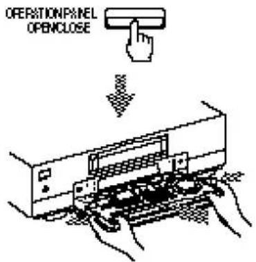

Note - Be careful not to push the OPERATION PANEL OPEN/CLOSE button.
(continued)
Index to parts and controls (continued)
Display window

1 TIME CODE indicator (45, 62) 2 REMAIN (remaining time) indicator (45) 3 TIMER indicator (40, 42) 4 REC (recording) indicator 5 DV OUT/IN indicator 6 S video input indicator (64, 77)
7 Cassette indicator 8 Channel indicator (39) 9 Current time/Quick timer/Frame indicator (39, 45, 48, 62) 10 Tape counter (45, 62) 11 Peak level meter (86)
Rear panel

1 RF UNIT CH3/CH4 switch (15, 92) 2 ILANC jack (62, 64) 3 LINE-1 IN jacks (64, 77) 4 AC IN connector 5 LINE-1 OUT jacks (12, 13)
6 LINE-2 OUT jacks ⑦ CABLE BOX CONTROL (CONTROL S OUT) jack (14, 22) 8 S LINK (CONTROL S IN) jack (13) 9 VHF/UHF IN/OUT connectors (14)
(continued)
Index to parts and controls (continued)
Remote commander
Front with cover closed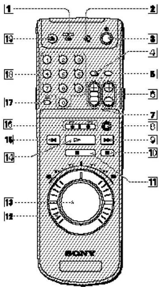
1 TV/VTR switch (9) 2 COMMAND MODE switch (9) 3 POWER button (40) 4 AUDIO MONITOR buttons (46) 5 TV/VTR button (9) 6 CHANNEL +/- buttons (39) 7 VOL (volume) +/- buttons (for TV only) (9) 8 ● REC button (39) 9 ▶▶FF button (38) 10 II PAUSE button (38) 11 ■ STOP button (38) 12 Shuttle ring (44) 13 Jog dial (44) 14 ▷ PLAY button (38) 15 ◀ REW button (38) 16 SEARCH 🏠/▶ buttons (38) 17 ENTER button (31) 18 Number buttons (31) 19 ▲ EJECT button (38)
Front with cover opened
1 DATA CODE button (45) 2 COUNTER SELECT button (45, 73) 3 COUNTER RESET button (45, 73) 4 COMMAND MODE switch (9) 5 PRINT button (91) 6 SEARCH SELECT button (49) 7 SEARCH ▶▶▶ button (49) 8 SEARCH ◀◀ button (49) 9 EXECUTE button (27, 54) 10 CURSOR ↑/↓/←/→ buttons (27, 54) 11 MENU button (27, 54) 12 FRAME ◀/▶ buttons (44) 13 ▶ SLOW button (44) 14 · 2 button (44) 15 DISPLAY button (45)
(3,5,13,14, are also used as Teletext buttons for TV)
Rear with cover opened
1 VCR Plus+ number buttons (40) 2 ONCE button (40) 3 DAILY button (40) 4 WEEKLY button (40) 5 TIMER CLEAR button (40) 6 VCR Plus+ button (40)
MENU chart
This VCR has a various functions available on the TV screen. To operate these functions, use the MENU buttons on the remote commander or control panel.
Refer to the pages indicated in ( ) for details.


![CLOCK SET SUM![].USE U++ != 10 ++1+cl Then push [SUM]uto Push = 1000 to quit](/content/2026/06/1301747/images/5e8ffa32e6956bc890ef17e8ac46c5e99a4d7016495e6d0cc4033dfb9b2c7e17.jpg)


TIM ER SET/CHECK (51)
Setting timer recordings.
You can also check, change and cancel the recordings, including the ones set with VCR Plus+ feature.
TUNER PRESET (30)
Tuning the VCR to receive broadcast channels.
CLOCK SET (27)
Enabling/disabling the auto AUTO CLOCK SET feature.
You can set the date and time manually if you select MANUAL.
SET VCR Plus+ CHANNELS (36)
Setting guide channels to the broadcasts you preset, or changing the program position order.
CABLE BOX CONTROL (33)
Setting the cable box/DSS receiver.
CASSETTE MEMORY ERASE (57)
Erasing the contents of the cassette memory of the DV or Mini DV tape.
Y/C DELAY (53)
Adjusting the difference in time between Y(luiminance) and C(chrominance).
ADVANCED OPTIONS (Page 1, Page 2) (54)
Changing the optional setup choices.
Index
12-bit/16-bit audio mode 4, 61
A
Adjusting the picture 53
AV hook up 12
Antenna hook up 18, 92
AFT (Auto Fine Tuning) 32
Audio dubbing 86
Audio recording mode 4, 46
Auto clock set 27
B
Bilingual program 47
C
Cable box 14, 16, 20, 33
Cable mouse 14, 22, 35
Cassette memory 6
erasing 57
searching 49
Channel setup 30
Cleaning 94
Clock 27
Command mode 9
Connection
to another VCR 64, 77
to a titler or an editing
controller 89
to a capture board or a video
printer 91
Copyright 7
D
Date search 49
DSS receiver 22, 33
DV
cassette 6
connection 4, 62, 64, 77
format 7
E, F, G, H
Easy Set Up 15, 17, 19, 21, 23, 25
Editing
audio dubbing 86
audio insert 75, 84
assemble editing 70
connections 64, 77
controls 66
copy a tape 67, 79
cutting out unwanted scenes 68, 80
methods 58
video insert 73, 82
Edit Window 4, 70
Hook ups 11
|
Insert editing audio insert 75, 84 video insert 73, 82 video on sound 74, 83
Insert editing audio insert 75, 84 video insert 73, 82 video on sound 74, 83
J, K
Jog dial 44
L
LANC connection 64 jack 62 mode 55
LANC connection 64 jack 62 mode 55
M, N
Menu changing options 54 chart 108
0
Operation panel 102
P
Photo search 49 Playback 38 at various speeds 38, 44 Protect tab 6
Q
Quick timer 48
R
Remote commander 9 Recording 39 Recording data 45 Remaining tape counter 45 RF unit 92
S
Safety tab 6 Searching using index functions 49 Shuttle ring 44 Stereo 1/2 track 7, 88 Sub code sector 7 Supplied accessories 8 S-video 12, 64 System-Link 13
T, U
Tape counter 45
Time code 62
Timer recording 40
cancelling 51
changing 51
checking 51
Tuner preset 30
V, W, X
VCR Plus+ 36, 40
Video printing 91
Video on sound 74, 83
Video capture board 91
Y
Y/C delay 53
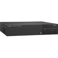

- DIGITAL VIDEO CASSETTE RECORDER
- WARNING
- TO PREVENT FIRE OR SHOCK HAZARD, DO NOT EXPOSE THE UNIT TO RAIN OR MOISTURE
- CAUTION
- PRECAUTIONS
- SAFETY
- INSTALLING
- INFORMATION
- FOR CUSTOMERS IN THE USA
- OWNER'S RECORD
- TABLE OF CONTENTS
- GETTING STARTED
- BASIC OPERATIONS
- ADDITIONAL OPERATIONS
- EDITING
- EDITING WITH LANC CABLE
- EDITING WITHOUT LANC CABLE
- OTHER EDITING FEATURES
- ADDITIONAL INFORMATION
- FEATURES
- HIGH-QUALITY DIGITAL PICTURE AND SOUND
- OVER 500 LINES OF HORIZONTAL RESOLUTION
- PCM-RECORDED DIGITAL SOUND
- CLEAR FRAME TECHNOLOGY THAT ENABLES CLEAR STILL PICTURES
- ADVANCED EDITING FEATURES
- DV
- DETACHABLE OPERATION PANEL
- EDIT WINDOW
- CONVENIENT FEATURES MADE POSSIBLE WITH THE DV FORMAT
- QUICK ACCESS WITH SUB-CODE DATA
- RECORDING DATA DISPLAY
- CASSETTE MEMORY SEARCH
- FEATURES (CONTINUED)
- USING DV CASSETTES
- CASSETTE MEMORY
- NOTES
- TO SAVE A RECORDING
- DV RECORDING FORMAT
- COPYRIGHT PRECAUTIONS
- ON RECORDING
- ON PLAYBACK
- GETTING STARTED STEP 1: UNPACKING
- STEP 2: SETTING UP THE REMOTE COMMANDER
- INSERTING THE BATTERIES
- SETTING THE COMMAND MODE SWITCH
- USING THE REMOTE COMMANDER
- STEP 2: SETTING UP THE REMOTE COMMANDER (CONTINUED)
- CONTROLLING OTHER TVS WITH THE REMOTE COMMANDER
- CODE NUMBERS OF CONTROLLABLE TVS
- STEP 3: HOOKUPS
- NOTE TO CATV SYSTEM INSTALLER
- SELECTING THE BEST HOOKUP OPTION
- BEFORE YOU GET STARTED
- AUDIO/VIDEO (A/V) HOOKUP
- NOTE
- C USE THIS HOOKUP IF YOUR TV HAS S-LINK™ FUNCTION
- A/V HOOKUP: VCR SETUP
- HOOKUP
- USING CABLE BOX CONTROL
- RECOMMENDED USE
- WHAT YOU CAN DO WITH THIS HOOKUP
- WHAT YOU CAN'T DO WITH THIS HOOKUP
- HOOKUP 1: VCR SETUP
- HOOKUP 1: VCR PLUS+ CHANNEL SETUP
- AUTOMATIC CLOCK SETTING
- NO CABLE BOX OR INCOMPATIBLE CABLE BOX WITH ONLY A FEW SCRAMBLED CHANNELS
- HOOKUP 2: VCR SETUP
- HOOKUP 2: VCR PLUS+ CHANNEL SETUP
- ANTENNA HOOKUP
- A USE THIS HOOKUP IF YOU'RE USING
- IF YOU CANNOT CONNECT YOUR ANTENNA CABLE TO THE VCR DIRECTLY
- HOOKUP 3: VCR SETUP
- HOOKUP 3: VCR PLUS+ CHANNEL SETUP
- INCOMPATIBLE CABLE BOX WITH MANY SCRAMBLED CHANNELS
- HOOKUP 4: VCR SETUP
- HOOKUP 4: VCR PLUS+ CHANNEL SETUP
- DSS (DIGITAL SATELLITE SYSTEM) RECEIVER
- HOOKUP 5: VCR SETUP
- YOU ARE NOW READY TO USE YOUR VCR
- INCOMPATIBLE CABLE BOX WITH ONLY A FEW SCRAMBLED CHANNELS, USING AN A/B SWITCH
- HOOKUP 6: VCR SETUP
- HOOKUP 6: VCR PLUS+ CHANNEL SETUP
- HOOKUP 6 (CONTINUED)
- TO RECORD AN UNSCRAMBLED CHANNEL
- TO RECORD A SCRAMBLED CHANNEL
- TO WATCH TV
- SETTING THE CLOCK
- USING THE AUTO CLOCK SET FEATURE
- BEFORE YOU START
- WHEN THE AUTO CLOCK SET FEATURE DOES NOT WORK WELL
- SETTING THE CLOCK (CONTINUED)
- IF THE CLOCK IS NOT ACTIVATED
- USING THE MANUAL CLOCK SET
- PRESS MENU
- PRESS THE CURSOR (↑/↓) BUTTONS
- PRESS THE CURSOR (←/→) BUTTONS
- SET THE MONTH USING THE CURSOR
- PRESS CURSOR → TO HIGHLIGHT THE
- PRESS EXECUTE TO START THE CLOCK
- PRESETTING CHANNELS
- TIP
- PRESETTING ALL RECEIVABLE CHANNELS AUTOMATICALLY
- PRESETTING/DELETING CHANNELS MANUALLY
- DISPLAY THE TUNER PRESET MENU
- SELECT THE CHANNEL TO PRESET OR DELETE
- SET MANUAL SET TO ADD OR ERASE, USING THE CURSOR (←/→) BUTTONS
- REPEAT STEPS 2 AND 3 TO PRESET OR DELETE CHANNELS AS REQUIRED, THEN PRESS EXECUTE
- PRESETTING CHANNELS (CONTINUED)
- IF THE PICTURE IS NOT CLEAR
- SETTING UP CABLE BOX CONTROL
- SETTING UP CABLE BOX CONTROL (CONTINUED)
- DSS RECEIVER/CABLE BOX BRANDS AND THE CORRESPONDING CABLE BOX CODE NUMBERS
- TO ENSURE CURRENT OPERATION
- TO CHECK THE CABLE BOX/DSS RECEIVER CONTROL SETTING
- IF YOU CANNOT GET YOUR VCR TO CONTROL THE CABLE BOX/DSS RECEIVER
- SETTING UP VCR PLUS
- HOW VCR PLUS+ WORKS
- HOW TO SET UP YOUR VCR
- BASIC OPERATIONS PLAYING A TAPE
- TIPS
- TURN ON YOUR TV AND SET IT TO THE VIDEO CHANNEL
- PRESS ▲ EJECT TO OPEN THE CASSETTE PANEL
- INSERT A CASSETTE
- PRESS ▷ PLAY TO START PLAYING
- RECORDING TV PROGRAMS
- PRESS CH +/- TO SELECT THE CHANNEL YOU WANT TO RECORD
- PRESS ● REC TO START RECORDING
- TO STOP RECORDING
- WATCHING A TV PROGRAM WHILE RECORDING ANOTHER
- RECORDING TV PROGRAMS USING VCR PLUS
- TO USE THE VCR AFTER SETTING THE TIMER
- SETTING THE TIMER MANUALLY
- PRESS MENU, THEN PRESS THE CURSOR (↑/↓) BUTTONS TO MOVE THE CURSOR (■) TO TIMER SET/CHECK AND PRESS EXECUTE
- SET THE DATE, START AND STOP TIMES, AND CHANNEL
- PRESS CURSOR → TO CONFIRM THE SETTING
- PRESS EXECUTE
- PRESS POWER TO TURN OFF THE VCR
- DAILY/WEEKLY RECORDING
- ADDITIONAL OPERATIONS PLAYING/SEARCHING AT VARIOUS SPEEDS
- USING JOG DIAL
- REWINDING THE TAPE AND STARTING PLAYBACK AUTOMATICALLY
- DISPLAYING TAPE INFORMATION
- DISPLAYING THE RECORDING DATA
- DISPLAYING THE REMAINING TAPE COUNTER
- USING THE TAPE COUNTER
- SELECTING THE SOUND
- PLAYING STEREO OR BILINGUAL PROGRAMS
- PLAYING THE DESIRED AUDIO TRACK
- RECORDING STEREO AND BILINGUAL PROGRAMS
- RECORDING STEREO PROGRAMS
- RECORDING BILINGUAL PROGRAMS
- TO SELECT THE BILINGUAL SOUND WHILE RECORDING
- SELECTING THE SOUND DURING PLAYBACK
- RECORDING TV PROGRAMS USING THE QUICK TIMER
- TO EXTEND THE DURATION
- SEARCHING USING THE INDEX FUNCTION
- SEARCHING IN THE LIST
- PRESS SEARCH SELECT TO SELECT THE SEARCH TYPE: INDEX, DATE, OR PHOTO SEARCH
- PRESS ◀◀◀ OR ▶▶◀ TO SELECT A RECORDING
- SEARCHING IN THE ORDER OF THE ACTUAL POSITIONS OF THE RECORDINGS ON THE TAPE
- PRESS SEARCH SELECT TO SELECT THE SEARCH TYPE
- PRESS I◀◀ OR ▶▶I REPEATEDLY TO LOCATE THE RECORDING YOU WANT
- SEARCHING USING THE INDEX FUNCTION (CONTINUED)
- HOW SIGNALS ARE RECORDED
- CHECKING/CHANGING/CANCELLING TIMER SETTINGS
- PRESS POWER TO TURN ON THE VCR
- PRESS MENU AND SELECT TIMER SET/CHECK
- CHECK THE TIMER SETTINGS
- CHANGE OR CANCEL THE TIMER SETTING
- CHECKING/CHANGING/CANCELLING TIMER SETTINGS (CONTINUED)
- WHEN THE TIMER SETTINGS OVERLAP
- ADJUSTING THE PICTURE (Y/C DELAY)
- CHANGING MENU OPTIONS
- MENU CHOICES
- CHANGING MENU OPTIONS (CONTINUED)
- ERASING THE CASSETTE MEMORY
- SELECT TO ERASE
- EDITING BEFORE EDITING
- EDITING METHODS
- COPYING A WHOLE TAPE
- CUTTING OUT UNWANTED SCENES
- ASSEMBLE EDITING
- INSERT EDITING
- VIDEO INSERT EDITING
- AUDIO INSERT EDITING (16-BIT MODE)
- AUDIO INSERT EDITING (12-BIT MODE)
- BEFORE EDITING (CONTINUED)
- AUDIO DUBBING
- BIT/16-BIT AUDIO MODES
- CHECKING THE AUDIO MODE
- HOW THE AUDIO MODE IS DECIDED
- CONNECTORS AND FEATURES USED FOR EDITING
- LANC JACK
- TIME CODE
- DV CONNECTION
- SELECTING THE CONNECTION FOR YOUR VCR
- WHEN USING THIS VCR AS THE PLAYBACK MACHINE
- CONNECTIONS
- TO A DIGITAL VCR WITH DV JACK
- TO A VCR WITHOUT DV JACK
- TO A CAMCORDER WITHOUT DV JACK
- PREPARATION
- ON THE PLAYER
- ON THE RECORDER (THIS VCR)
- CONNECTIONS (CONTINUED)
- CONTROLLING THE OTHER VCR WITH LANC CONNECTION
- COPYING A TAPE
- PRESS DUPLICATE ENTIRE TAPE
- PRESS START/PAUSE
- TO STOP COPYING
- SEARCH FOR THE POINT TO RESUME RECORDING (®)
- PRESS START/PAUSE TO RESUME RECORDING
- TO CUT OUT OTHER SCENES, REPEAT STEPS 4 TO
- TO FINISH EDITING, PRESS START/PAUSE TO SET THE VCRS TO RECORDING PAUSE, THEN PRESS EDIT STANDBY
- LOOKING AT THE EDIT WINDOW
- IF THE OTHER VCR HAS A TIME CODE FUNCTION, SET IT TO THE TIME CODE DISPLAY
- PRESS ASSEMBLE
- DESIGNATE THE IN POINT OF THE FIRST EVENT
- DESIGNATE THE OUT POINT
- TO DESIGNATE OTHER EVENTS, REPEAT STEPS 3 AND
- TO CHECK/CHANGE EVENTS
- LOCATE THE POINT YOU WANT TO START RECORDING ON THIS VCR
- ASSEMBLE EDITING (CONTINUED)
- PRESS START / PAUSE
- TO ASSEMBLE EDIT MORE THAN 10 EVENTS
- TO STOP ASSEMBLE EDITING
- TO END ASSEMBLE EDITING
- PRESS COUNTER SELECT SO THAT THE TAPE COUNTER APPEARS
- LOCATE THE END POINT (Ⓐ) OF THE SCENE TO BE RECORDED OVER
- VIDEO INSERT EDITING (CONTINUED)
- LOCATE THE START POINT (®) OF THE SCENE TO BE RECORDED OVER
- PRESS VIDEO INSERT
- LOCATE THE PLAYBACK START POINT (©) OF THE SOURCE TAPE
- AUDIO INSERT EDITING
- LOCATE THE END POINT OF THE SCENE TO BE RECORDED OVER
- LOCATE THE START POINT OF THE SCENE TO BE RECORDED OVER
- PRESS STEREO 1 INSERT AND/OR STEREO 2 INSERT AS FOLLOWS
- WHEN YOU RECORD FROM LINE INPUTS
- AUDIO INSERT EDITING (CONTINUED)
- LOCATE THE PLAYBACK START POINT OF THE SOURCE TAPE
- HOW THE AUDIO RECORDING MODE SELECTION AFFECTS EDITING RESULTS
- WHEN YOU RECORD FROM DV INPUT
- LOCATE THE END POINT (A) OF THE SCENE TO BE RECORDED OVER
- LOCATE THE START POINT (⑧) OF THE SCENE TO BE RECORDED OVER
- LOCATE THE PLAYBACK START POINT OF THE SOURCE TAPE (©), THEN SET THE VCR TO PLAYBACK PAUSE
- PRESS THE PAUSE BUTTON ON THE OTHER VCR TO START PLAYBACK. AT THE BEGINNING OF THE SCENE YOU WANT TO REPLACE, PRESS III PAUSE ON THIS VCR TO START RECORDING
- PRESS ■ STOP ON THE OTHER VCR
- LISTENING TO THE INSERTED/DUBBED SOUND
- CONNECTING A TITLER OR EDITING CONTROLLER
- CONNECTING A TITLER OR EDITING CONTROLLER (CONTINUED)
- CONNECTING AN EDITING CONTROLLER
- CONNECTING A CAPTURE BOARD OR VIDEO PRINTER
- CONNECTING THE DVBK-1000 CAPTURE BOARD
- CONNECTING A VIDEO PRINTER
- ADDITIONAL INFORMATION GENERAL SETUP INFORMATION
- SETTING THE RF UNIT
- ATTACHING THE EXTERNAL ANTENNA CONNECTOR
- ATTACHING A UHF/VHF BAND MIXER
- NOTES ON THE VIDEO CASSETTE RECORDER
- DO NOT INSTALL THE UNIT IN A PLACE SUBJECT TO DIRECT SUNLIGHT OR HEAT SOURCES
- DO NOT INSTALL THE UNIT IN AN EXTREMELY HOT PLACE
- IF THE UNIT IS BROUGHT DIRECTLY FROM A COLD TO A WARM LOCATION
- DO NOT PLACE HEAVY OBJECTS ON THE UNIT
- DO NOT HANDLE THE RECORDER ROUGHLY
- TO AVOID DAMAGING THE CABINET FINISH
- DO NOT CLEAN THE CABINET WITH THINNER OR BENZINE
- CLEAN THE CABINET WITH A SOFT DRY CLOTH
- DO NOT PUT MAGNETIC OBJECTS CLOSE TO THE UNIT
- CHECKING THE VIDEO HEADS EVERY 1000 HOURS
- PRECAUTIONS (CONTINUED)
- CLEANING OF THE VIDEO HEADS
- NOTES ON THE VIDEO CASSETTES
- USABLE CASSETTES
- CLEANING THE TERMINAL
- WHEN AFFIXING A LABEL ON THE CASSETTE
- AFTER USING A CASSETTE
- ABOUT MOISTURE CONDENSATION
- IF MOISTURE CONDENSATION OCCURRED
- TROUBLESHOOTING
- TROUBLESHOOTING (CONTINUED)
- SPECIFICATIONS
- SYSTEM
- RECORDING FORMAT
- VIDEO SIGNAL
- RECORDING TIME
- FAST-FORWARD AND REWIND TIME
- VIDEO
- QUANTIZATION WORD LENGTH
- SAMPLING FREQUENCY
- HORIZONTAL RESOLUTION
- AUDIO
- TUNER SECTION
- TUNING SYSTEM
- AUDIO TUNING SYSTEM
- CHANNEL COVERAGE
- ANTENNA
- TIMER SECTION
- CLOCK
- TIMER INDICATION
- TIMER SETTING
- POWER BACK-UP
- SPECIFICATIONS (CONTINUED)
- INPUTS AND OUTPUTS
- CONTROL S IN
- DV IN/OUT
- LINE IN 1 AND
- LINE OUT 1 AND
- HEADPHONE JACK
- GENERAL
- POWER REQUIREMENTS
- POWER CONSUMPTION
- OPERATING TEMPERATURE
- STORAGE TEMPERATURE
- DIMENSIONS
- MASS
- SUPPLIED ACCESSORIES
- INDEX TO PARTS AND CONTROLS
- FRONT PANEL
- INDEX TO PARTS AND CONTROLS (CONTINUED)
- OPERATION PANEL
- DISPLAY WINDOW
- REAR PANEL
- REMOTE COMMANDER
- MENU CHART
- TIM ER SET/CHECK (51)
- TUNER PRESET (30)
- CLOCK SET (27)
- SET VCR PLUS+ CHANNELS (36)
- CABLE BOX CONTROL (33)
- CASSETTE MEMORY ERASE (57)
- Y/C DELAY (53)
- ADVANCED OPTIONS (PAGE 1, PAGE 2) (54)
- INDEX
- A
- B
- C
- D
- E, F, G, H
- INSERT EDITING AUDIO INSERT 75, 84 VIDEO INSERT 73, 82 VIDEO ON SOUND
- JOG DIAL
- LANC CONNECTION 64 JACK 62 MODE
- M, N
- P
- Q
- R
- S
- T, U
- V, W, X
- Y
Brand : SONY
Model : DHR-1000
Category : VCR