
UVW-1800P - VCR SONY - Free user manual and instructions
Find the device manual for free UVW-1800P SONY in PDF.



| Product Type | Professional VCR (Betacam SP) |
| Model | UVW-1800P |
| Brand | Sony |
| Dimensions (W x H x D) | 430 x 132 x 410 mm (16.9 x 5.2 x 16.1 inches) |
| Weight | 15 kg (33 lbs) |
| Power Supply | 100-240 V AC, 50/60 Hz |
| Power Consumption | 80 W |
| Video Format | Betacam SP |
| Recording/Playback Time | Up to 90 minutes with large cassette |
| Video Output | Composite, Y/C, component (BNC) |
| Audio Output | 2 channels (XLR, RCA) |
| Control Interface | RS-422, RS-232C, parallel remote |
| Editing Functions | Insert/assemble editing, preview, Jog/Shuttle |
| Time Code | LTC/VITC reader/generator |
| Operating Temperature | 5°C to 40°C (41°F to 104°F) |
| Storage Temperature | -20°C to 60°C (-4°F to 140°F) |
| Humidity | 20% to 80% (non-condensing) |
| Head Drum | Replaceable (cleaning recommended every 500 hours) |
| Maintenance | Clean tape path with specified cleaning cassette; avoid dust |
| Safety | Class I equipment; use grounded outlet; do not remove cover |
| Spare Parts | Available through Sony authorized service centers |
Frequently Asked Questions - UVW-1800P SONY
User questions about UVW-1800P SONY
0 question about this device. Answer the ones you know or ask your own.
Ask a new question about this device
Download the instructions for your VCR in PDF format for free! Find your manual UVW-1800P - SONY and take your electronic device back in hand. On this page are published all the documents necessary for the use of your device. UVW-1800P by SONY.
USER MANUAL UVW-1800P SONY
Videocassette Recorder
Model:
UVW-1800/1800P
Operating Instructions page i (E)
Before operating the unit, please read this manual thoroughly and retain it for future reference.
The model and serial numbers are located at the rear. Record the serial number in the space provided below. Refer to these numbers whenever you call upon your Sony dealer regarding this product.
Model No. UVW-1800
Serial No. -
WARNING
To prevent fire or shock hazard, do not expose the unit to rain or moisture.

RISK OF ELECTRIC SHOCK
DO NOT OPEN

CAUTION TO REDUCE THE RISK OF ELECTRIC SHOCK
DO NOT REMOVE COVER (OR BACK)
NO USER-SERVICEABLE PARTS INSIDE
REFER SERVICING TO QUALIFIED SERVICE PERSONNEL

This symbol is intended to alert the user to the presence of uninsulated "dangerous voltage" within the product's enclosure that may be of sufficient magnitude to constitute a risk of electric shock to persons.

This symbol is intended to alert the user to the presence of important operating and maintenance (servicing) instructions in the literature accompanying the appliance.
Caution
Television programs, films, video tapes and other materials may be copyrighted. Unauthorized recording of such material may be contrary to the provisions of the copyright laws.
For the customers in USA
This equipment has been tested and found to comply with the limits for a Class A digital device, pursuant to Part 15 of the FCC Rules. These limits are designed to provide reasonable protection against harmful interference when the equipment is operated in a commercial environment. This equipment generates, uses, and can radiate radio frequency energy and, if not installed and used in accordance with the instruction manual, may cause harmful interference to radio communications. Operation of this equipment in a residential area is likely to cause harmful interference in which case the user will be required to correct the interference at his own expense.
You are cautioned that any changes or modifications not expressly approved in this manual could void your authority to operate this equipment.
The shielded interface cable recommended in this manual must be used with this equipment in order to comply with the limits for a digital device pursuant to Subpart B of Part 15 of FCC Rules.
For the customers in Canada
This apparatus complies with the Class A limits for radio noise emissions set out in Radio Interference Regulations.
For the customers in the United Kingdom
WARNING
THIS APPARATUS MUST BE EARTHED
IMPORTANT
The wires in this mains lead are coloured in accordance with the following code:
Green-and-yellow
Earth
Blue
Neutral
Brown:
Live
As the colours of the wires in the mains lead of this apparatus may not correspond with the coloured markings identifying the terminals in your plug, proceed as follows:
The wire which is coloured green-and-yellow must be connected to the terminal in the plug which is marked by the letter E or by the safety earth symbol ^ or coloured green or green-and-yellow.
The wire which is coloured blue must be connected to the terminal which is marked with the letter N or coloured black.
The wire which is coloured brown must be connected to the terminal which is marked with the letter L or coloured red.
Contents
Precautions ....3 (E)
Chapter 1
Overview
Features....1-2 (E)
Chapter 2
Identification of
Parts and Controls
Front Panel 2-2 (E)
Rear Panel.... 2-5 (E)
Chapter 3
Preparations
Before Use 3-2 (E)
Cassettes....3-3(E)
Cassettes Which Can Be Used ....3-3 (E)
Inserting and Ejecting a Cassette ....3-3 (E)
Record Inhibit Function 3-4 (E)
Reference Video Signals 3-5 (E)
Chapter 4
Recording and
Playback
Playback Operation 4-2 (E)
Preparation for Playback.... 4-2 (E)
Playback Operation 4-3 (E)
Recording Operation 4-4 (E)
Preparation for Recording 4-4 (E)
Recording Operation 4-6 (E)
Superimposed Text Information....4-7 (E)
Chapter 5
Editing
Cut Editing....5-2 (E)
A/B Roll Editing 5-6 (E)
Phase Adjustments....5-11 (E)
Chapter 6
Time Data
Displaying Time Data 6-2 (E)
Settings for Longitudinal Time Code and User Bits ......6-3 (E)
Synchronizing the Internal Time Code Generator With an
External Time Code Generator 6-6 (E)
Contents
Chapter 7 Menus
Chapter 8 Maintenance
Chapter 9 Operational Problems
Appendixes
Menu Organization....7-2 (E)
Hierarchical Structure 7-2 (E)
Menu Screens....7-3 (E)
Menu Operations....7-8 (E)
Buttons Used to Change the Setting....7-8 (E)
Operation Sequence 7-9 (E)
Self-Diagnosis Functions.... 8-2 (E)
Condensation 8-3 (E)
Regular Checks and Maintenance....8-4 (E)
Digital Hours Meter 8-4 (E)
Head Cleaning....8-5 (E)
Alarm Messages.... 9-2 (E)
Trouble-Shooting Chart....9-4 (E)
Specification.....A-2(E)
Glossary....A-6 (E)
Index 1-1 (E)
To take best advantage of the many features of this unit, note the following important points.
Usable cassette tapes (see page 3-3(E))
Use only metal cassette tapes with this unit. Do not use oxide tapes.
Reference video input (see page 3-5(E))
When recording or playing back videotapes on this unit, always input a composite video signal synchronized with the video signal to be used to the REF. VIDEO INPUT connector. Especially when recording and editing, failure to input a reference video signal to the REF. VIDEO INPUT connector will prevent the built-in time base corrector (TBC) from functioning correctly, causing picture breakup. Even if you are recording only audio signal or time code, do not fail to input a reference video signal.
Input video signal type selection (see page 4-5(E))
For recording, it is important that the VIDEO IN switch on the subsidiary control panel is correctly set to match the type of video signal input. In particular, when inputting a component signal, set this switch to the "Y-R,B" position, and set the component signal input connector selection switch on the rear panel to the appropriate position. If these switches are not set correctly, not only will recording not be possible, but the input signal will also not appear on the monitor.
Setting the cassette record-inhibit plug (see page 3-4(E))
Recording on a cassette is impossible when its record-inhibit plug is pushed in. If the record-inhibit plug is pushed in on the cassette you are going to use, either use a new tape, or pull out the plug and use the tape after making sure that it contains no important material.
Controlling tape transport remotely (see page 7-3(E))
The tape transport buttons on this unit are normally disabled when the REMOTE indicator is lit. However, you can use these buttons if you set the LOCAL ENABLE menu item to ALL ENABLE. The factory default setting for this item is STOP & EJECT.
Storing in a rack
When installing this unit in a standard 19-inch rack, you can stack up to three units in one rack. When stacking four or more units, be sure to leave space equivalent to one unit height, or 44.45 mm (1 3/4 inches) between units.
Chapter 1 Overview
This chapter overviews the features of the UVW-1800/1800P.
Features.... 1.2 (E)
The UVW-1800/1800P is a Betacam SP videocassette recorder, capable of recording and playing back composite video, component video and analog audio signals. With an external control unit connected, jog and shuttle functions are available, and the unit can be used as the recorder in an editing system.
Betacam SP format
Excellent video and audio characteristics
Compared with a conventional format, Betacam SP format provides better video and audio performance, with improved signal-to-noise ratio, frequency characteristics, and detail reproduction, and greatly enhanced overall video and audio quality.
Compatibility with other Betacam SP VTRs
A metal tape cassette recorded on this unit can also be played back on other Betacam SP VTRs. Again, metal tape cassettes recorded on other Betacam SP VTRs can be played back on the UVW-1800/1800P. The cassette size is detected automatically.
Full range of recording and playback functions
Built-in time code generator and reader
The built-in time code generator allows the unit to record time codes (LTC or user bits) simultaneously with the video and audio signals. The built-in time code reader allows the unit to read time codes (LTC or user bits) from a tape.
Built-in time base corrector (TBC)
The built-in time base corrector allows you to obtain a stable playback picture with no horizontal jitter or color fluctuation.
Microprocessor servo system
Four microprocessor-controlled DC motors provide direct drive for the drum, capstan and reels, enabling quick and accurate tape access.
Audio noise reduction
Longitudinal audio tracks 1 and 2 use the same Dolby C-type noise reduction 21 as a conventional Betacam SP system. These circuits are always operating when recording or playing back.
1) Because this unit does not record the AFM carrier wave, noise may be heard when tapes recorded on this unit are played back by other VTRs in the BVW series. If necessary, lower the audio levels of channels 3 and 4 on the other VTR.
2) Dolby noise reduction manufactured under license from Dolby Laboratories Licensing Corporation. "DOLBY" and the double-D symbol DO are trademarks of Dolby Laboratories Licensing Corporation.
Other features
Compact, power-saving design
The unit is light and simple, and very energy-efficient.
Menu-based set-up system
All the initial settings for system operation conditions and so forth are accessed through a simple menu system, from the subsidiary control panel.
Remote control function
The unit can be operated from a remote control unit through the RS-422A serial interface.
It is also possible to use the CONTROL S connector on the front panel to connect a simple remote control unit (SIRCS type remote control unit such as an SVRM-100) to carry out search operations.
Digital hours meter
The digital hours meter keeps cumulative totals of four values: the total hours powered on, the drum rotation time, the tape running time, and the numbering of threading/unthreading operations. These are displayed as superimposed text on the video monitor.
Superimposed text output
The VIDEO 2 (SUPER) OUTPUT connector provides a monitor video output which can have various information (time codes, tape speed, system settings, etc.) superimposed on it. The superimpose function can be enabled or disabled as required.
S-Video connectors
With VTRs or other peripheral equipment having S-Video connectors, these connectors provide a high-grade interface for video signal transfer.
Self-diagnosis functions
If an operating fault occurs, the system attempts to diagnose the problem, and produces an error code on the time counter display and superimposed video output.
Alarm indications
If an erroneous operation or connection is made, the system superimposes information on the monitor screen giving the nature of the error and actions to be taken. The cause of the problem is also indicated in the time counter display.
Chapter 2 Identification of Parts and Controls
This chapter lists the names of all the controls and other components used in the operation of the unit.
Front Panel 2-2 (E)
Rear Panel 2-5 (E)
Front Panel


Front Panel
Tape transport section
Tape transport section
Rear Panel

Rear Panel
Video inputs

Video inputs
Side control panel
Side control panel
Indicators
Subsidiary control panel
The subsidiary control panel is behind a flap on the front panel. Open the flap as shown in the figure.

Pull the flap forward and down, then push into the panel.
Accessing the subsidiary control panel
● Switches, Controls and Adjusters
25 AUDIO INPUT LEVEL controls These adjust the audio input levels for each of channels 1 and 2 when recording.

Selects whether the unit is controlled remotely from a device connected to the REMOTE connector on the rear panel, or locally from the control panel.
21 CTL/LTC/U-BIT switch
Selects the type of time data (CTL/LTC or user bits) displayed.
Note
When the REMOTE/LOCAL switch is set to REMOTE, this switch is ignored, and the selection is made from the external device connected.
22 VIDEO IN selector switch
Selects the type of video input signal for recording or playing back a component signal (the "Y-R,B" position), a composite signal (COMPOSITE position), or an S-VIDEO signal (S-VIDEO position).
23 CHARACTER switch
Determines whether or not character information such as time codes is superimposed on the video output signal from the VIDEO 2 (SUPER) OUTPUT connector.
24 TC (time code) IN selector switch
Selects whether the time code from the internal time code generator is used (INT position) or the time code input from an external source (EXT position).
Adjust this when necessary to accurately adjust the subcarrier phase of the output signal (composite) of the unit with respect to the reference video signal.
27 SYNC adjuster
Adjust this when necessary to accurately adjust the sync phase of the output signal (composite) of the unit with respect to the reference video signal.
● Menu, control, Time code, Digital Hours Meter Button
32 TC (time code) PRESET button-
Press this button to preset the LTC or user-bit value shown on the time counter display.
For details of how to set time code values, see the section "Settings for Longitudinal Time Code and User Bits" (page 6-3(E)).
33 HOURS METER button
Pressing this button switches the information superimposed on the monitor screen to show the digital hours meter values. The time counter display also shows the hours meter information at the same time. Pressing the button again returns to the normal indications.
For details of the digital hours meter, see the section "Digital Hours Meter" (page 8-4(E)).
28 MENU button
Pressing this button displays menu options on the monitor screen and the time counter display. Pressing the button again returns to normal operating mode.
For details of menu operations, see the section "Menu Operations" (page 7-8(E)).

29 Arrow direction (1 1 2) buttons Use these buttons to move around the menu settings, and also for setting time code values.
For details of how to set time code values, see the section "Settings for Longitudinal Time Code and User Bits" (page 6-3(E)).
30 RESET (NO) button
This button resets menu settings to their factory defaults, resets a time code value to zero, and is also used for a negative response to a menu question.
31 SET (YES) button
This button confirms new menu or time code settings. It is also used for a positive response to a menu question.
Video outputs
Video outputs
Audio inputs and outputs
Audio inputs and outputs
Power, time code and control signals

Always power off the UVW-1800/1800P before connecting a remote control unit to the TBC REMOTE connector (Load current: Max. 300mA)
Power, time code and control signals
Chapter 3 Preparations
This chapter describes various preparatory aspects of operation of the UVW-1800/1800P.
Before Use 3-2 (E)
Cassettes 3-3 (E)
Cassettes Which Can Be Used. 3-3 (E)
Inserting and Ejecting a Cassette.... 3-3 (E)
Record Inhibit Function.... 3-4 (E)
Reference Video Signals.... 3-5 (E)
Before Use
Safety notes
Power supply
- Ensure that the unit is connected to a power supply of the correct rating.
- Do not place any heavy objects on the power cord, and be careful not to damage the power cord. Using a damaged power cord is dangerous.
- When disconnecting the power cord, do not pull the cord itself, hold the plug while pulling it out.
Do not dismantle the unit
Do not remove the casing. If you insert your hand there is a danger of electric shock.
Do not drop foreign objects into the casing.
If flammable objects, metal objects, water, or other undesirable substances enter the casing, this can cause malfunction.
In the event of a malfunction
If there should be a strange sound, smell, or smoke emanating from the unit, immediately power off the unit, disconnect the power supply and all signal connections, then refer to your supplier or Sony service representative.
Notes on operation
Operation and storage locations
Avoid operation or storage in any of the following places.
- Locations subject to extremes of temperature (operating temperature range 5 °C to 40 °C (41 °F to 104 °F)).
- Locations subject to direct sunlight for long periods, or close to heating appliances (note that the interior of a car left in summer with the windows closed can exceed 50 °C (122 °F)).
Operate the unit in a horizontal position
This unit is designed to be operated in a horizontal position. Do not operate it on its side, or tilted through an excessive angle (exceeding 20°).
Avoid violent impacts
Dropping the unit, or otherwise imparting a violent shock to it, is likely to cause it to malfunction.
Do not obstruct ventilation openings
To prevent the unit from overheating, do not obstruct the ventilation openings, for example by wrapping the unit in a cloth while it is in operation.
Care
If the casing or panel is dirty, wipe it gently with a soft dry cloth. In the event of extreme dirt, use a cloth steeped in a neutral detergent to remove the dirt, then wipe with a dry cloth. Applying alcohol, thinners, insecticides, or other volatile solvents may result in deforming the casing or damaging the finish.
Shipping
• Always remove the cassette before shipping the unit. - Pack the unit in its original carton or equivalent packing, and take care not to impart violent shocks in transit.
Cassettes
Cassettes Which Can Be Used
This unit only accepts metal tapes.
Use the following '1/2-inch Betacam SP cassettes.
| Metal tape | |
| Small (S) cassettes | BCT-5MA/10MA/20MA/30MA, UVWT-10MA/20MA/30MA |
| Large (L) cassettes | BCT-5MLA/10MLA/20MLA/30MLA/60MLA/90MLA, UVWT-60MLA/90MLA |
Inserting and Ejecting a Cassette
Always check that the unit is powered on before attempting to insert or eject a cassette.
Inserting a cassette

Inserting a cassette
1 Turn the POWER switch on.
2 Check the following points, then insert the cassette.
- The cassette must be inserted with the side that the tape is visible uppermost. • There must be no slack in the tape.
- There must be no message "HUMID!" in the time counter display.
- The cassette must be inserted with the side that the tape is visible uppermost.
- There must be no slack in the tape.
- There must be no message "HUMID!" in the time counter display.
For details of how to remove slack in the tape, see the section "Removing slack in the tape" (on the next page).
If the message "HUMID!" appears in the time counter display, see Section "Condensation" (page 8-3(E)).
To insert a small cassette, align it with the marks on the cassette compartment.
The cassette is automatically drawn into the unit, and the tape wound round the head drum. The tape is stationary while the head drum rotates, and the STOP button lights.

Cassettes
Removing slack in the tape
Carefully rotate one of the reels with your finger in the direction of the arrows until it stops.

Removing slack in the tape
No double insertion of cassettes
When you insert a cassette, the orange lock-out plate appears in the cassette compartment to prevent double insertion.
Ejecting the cassette
Press the EJECT button.
The tape is wound back into the cassette (this takes several seconds), and then the cassette is ejected from the unit.
If the time counter display is showing CTL values, it is reset.
Record Inhibit Function
To protect recorded material which you wish to keep, press in the record-inhibit plug on the cassette.

Record-inhibit plug
When you insert a cassette with the record-inhibit plug pushed in into the cassette compartment, the REC INHIBIT indicator lights, and it is not possible to record.
To re-record on the cassette, return the record-inhibit plug to its original position.
Reference Video Signals
When this unit is being used, a composite video signal, synchronized to the signal being used must be input to the REF. VIDEO INPUT connector to enable the time base corrector (TBC) to operate correctly, and ensure stable operation.
If no reference video signal is input, then during recording or editing, or in EE mode the monitor screen will tend to drift vertically, as shown in the figure below.

The monitor screen and the time counter display also show alarm messages. (Example: When the VIDEO 2 (SUPER) OUTPUT connector is used with the "REF. ALARM" set to ON in the menu.)

During playback, a monitor picture is normally stable without a reference video signal input.
For details of changing the menu settings, see the section "Menu Operations" (page 7-8(E)).
Chapter 4 Recording and Playback
This chapter describes the preparation necessary before using the unit for recording or playback, including connections and switch settings, and basic operating procedures. It also describes the text information which can be superimposed on the monitor screen.
Playback Operation ....4-2 (E)
Preparation for Playback....4-2 (E)
Playback Operation.... 4-3 (E)
Recording Operation.... 4-4 (E)
Preparation for Recording....4-4 (E)
Recording Operation.... 4-6 (E)
Superimposed Text Information ....4-7 (E)
Playback Operation
This section describes the connections, switch settings, and basic operating procedures for playback of both video and audio signals.
Preparation for Playback
Connect the unit to the monitor and make the switch settings as shown in the following figure.

a) The VIDEO IN connectors of the PVM-1444Q are provided with automatic termination function.
Connections and switch settings


UVW-1800/1800P Operation
1 Insert a cassette.
The STOP button lights, then a few seconds later the tape is ready to start running. At this point a still picture appears on the monitor. Always be sure to use a metal tape.
2 Press the PLAY button.
Playback begins.
To stop playback
Press the STOP button.
This puts the UVW-1800/1800P into stop mode. This unit automatically enters standby-off mode if it is left in stop mode for eight minutes.
You can change the time to switch to stand-by off mode in the TAPE PROTECTION menu. For details, see under "TAPE PROTECTION" (page 7-6(E)).
If the tape reaches the end during playback
The tape is automatically rewound to the beginning and the unit stops. You can disable this automatic rewind function using the menu.
For details, see "AUTO REW" (page 7-3(E)).
Adjusting the audio playback volume
Carry this out on the monitor.
Simple search function
With the F. FWD/REW item in the AUTO EE SELECT of OPERATIONAL FUNCTION menu set to PB, holding down the F FWD or REW button provides a monochrome search function at 16 times normal speed in the forward or reverse direction respectively. Press the PLAY button again to return to normal playback.
Recording Operation
This section describes the connections, switch settings, and basic operating procedures for recording a component video signal and audio signal.
Preparation for Recording
Connect this unit as the recorder and a UVW-1600/1600P as the player as shown in the following figure. To check the video and audio signals being recorded, connect the UVW-1800/1800P to a monitor as described in the Section "Playback Operation" (page 4-2(E)).
![graph TD A["Video signal generator (from example, Sony Tektronix TSG 130/TSC 131A)"] --> B["BNC cable"] C["REF. VIDEO 75 Ω termination switch: ON"] --> D["UVW-1800/1800P (recorder)"] E["Component input connector selection switch: COMPONENT 2 (upper position)"] --> F["AUDIO INPUT 600 Ω ON/OFF switch:…](/content/2026/06/1301732/images/a182f1b1e7266c5a7f36f7edb793d9a1a0bcd12d3d888adfeb742638cf8f63a6.jpg)
Connections
CB3
If you do not input a reference video signal, the monitor picture will be subject to vertical instability. When carrying out recording, always input a reference video signal.
For details of reference video signals, see the Section "Reference Video Signals" (page 3-5(E)).
Switch and control settings
After completing the connections, make the switch and control settings as follows.

Switch and control settings
1. Power on the video monitor. 2. Set the input selector of the monitor to the input connector connected to the UVW-1800/1800P. 3. Following the instructions in the appropriate operation manual, prepare the player for playback. 4. Power on the UVW-1800/1800P. 5. Set the VIDEO IN selector switch to Y-RJB. 6. Set the time counter display selector switch according to the time data to be used. 7. Adjust the AUDIO INPUT LEVEL controls so that the audio level meters indicate around 0 VU when the audio signal is at its maximum.
Recording Operation
Recording Operation
In order to carry out recording of the video and audio signals, check that you have made the connections and carried out the switch setting procedure correctly, then use the following procedure.

Operation
1 Insert a cassette in the UVW-1800/1800P. Always be sure to use a metal tape. Before inserting the cassette, check that it is not record-inhibited. For details see the Section "Record Inhibit Function" (page 3-4(E)). 2 Check that the REC INHIBIT indicator is not lit. 3 Hold down the REC button, and press the PLAY button. Recording starts. 4 Press the PLAY button on the player. Playback starts.
To stop recording
Press the STOP button.
When the subsidiary control panel CHARACTER switch is in the ON position, the video signal output from the VIDEO 2 (SUPER) OUTPUT connector includes superimposed indications of time data and the operating state of this unit.
Selecting the information displayed and the character type and position of the indications
The information displayed and the character type and position of the indications can be selected by using the menu item "DISPLAY CONTROL." The factory default settings are as follows.
Information displayed : Time data selected by the time counter display selective switch, and the operating status of the unit
Character type : White characters on a black background Character position : Bottom center of the screen
For details of the setting method, see under "DISPLAY CONTROL" (page 7-4(E)).

Displayed information (factory default)
1Type of time data
This indicates the type of time data as follows.
| Indication | Meaning |
| CTL | CTL counter data |
| TCR | LTC reader data |
| UBR | LTC reader user bit data |
| TCG | Time code data from time code generator |
| UBG | User bit data from time code generator |
| T+R | Time code data from time code reader.Interpolated by the time code reader to make up for the time code data not correctly read from the tape. |
| U+R | User bit data from time code reader.Last data is retained by the time code reader, as the new data has not been read correctly from the tape. |
Superimposed Text Information
Drop-frame indication for time code reader (onUVW-1800only)
"." : A single dot indicates drop-frame mode. ":" : Two dots (i.e. a colon) indicate non-drop-frame mode.
Drop-frame indication for time code generator (on UVW-1800 only)
"." : A single dot indicates drop-frame mode. ":" : Two dots (i.e. a colon) indicate non-drop-frame mode.
UVW-1800/1800P operating status
| Indication | Operating status | |
| THREADING | Cassette is inserted, and tape is being threaded. | |
| UNTHREADING | Tape is being unthreaded to eject cassette. | |
| CASSETTE OUT | No cassette is inserted. | |
| STANDBY OFF | Tape is not on standby. | |
| T.RELEASE | Tape tension is released. | |
| STOP | Tape is stopped. | |
| F.FWD | Fast forward. | |
| REW | Rewind. | |
| PREROLL | Preroll. | |
| PLAY | Play (servo not locked) | |
| PLAY | LOCK | Play (servo locked) |
| PLAY | PAUSE | Playback pause |
| REC | Recording (servo not locked) | |
| REC | LOCK | Recording (servo locked) |
| REC | PAUSE | Recording pause |
| EDIT | Edit mode (servo not locked) | |
| EDIT | LOCK | Edit mode (servo locked) |
| JOG | STILL | Still picture in jog mode |
| JOG | FWD | Jog mode in forward direction (▶indicator lights) |
| JOG | REW | Jog mode in reverse direction (◀indicator lights) |
| SHUTTLE | (speed) | Shuttle mode ( playback speed) |
| PAUSE | Shuttle mode playback pause | |
Chapter 5 Editing
By connecting two or more UVW-1800/1800P units or using UVW-1600/1600P units as players, and connecting an editing control unit such as a PVE-500, it is possible to assemble an editing system; the UVW-1800/1800P can be used as the recorder in such an editing system. This section describes the connections required for cut editing and for A/B roll editing, and the phase adjustments required for editing.
Cut Editing 5-2 (E)
A/B Roll Editing.... 5-6 (E)
Phase Adjustments 5-11 (E)
Cut Editing
The figure below illustrates a system for cut editing using the UVW-1800/1800P with a UVW-1600/1600P.
For details of editing operations, refer to the operation manual for the editor being used. For details of the connections and settings on each of the other pieces of equipment, refer to the respective operation manuals.

Example configuration of system for cut editing (component signals)
Switch settings on the UVW-1800/1800P (recorder) and UVW-1600/1600P (player)
| Switches | UVW-1800/1800P | UVW-1600/1600P |
| REMOTE/LOCAL switch | REMOTE | REMOTE |
| VIDEO IN selector switch | Y-R, B | - |
| Component input connector selection switch | 1 | - |
| AUDIO INPUT 600 Ω ON/OFF switch | ON | - |
| REF. VIDEO 75 Ω termination switch | ON | OFF |
Monitoring the video signals
To monitor the video signals, connect monitors as shown in the figure below. The connections are the same for the recorder and player.
To obtain superimposed information on the monitor screen, set the CHARACTER switch to the ON position.

Connecting a video monitor
Cut Editing
Reference video signal and editor connections


Reference video signal and editor connection
Video and audio signal connections
Using BNC cable and VDC-C5 dubbing cable
Video and audio signal connection 1
Using BNC cables
Video and audio signal connection 2
A/B Roll Editing
The figure below illustrates a system for A/B roll editing using the UVW-1800/1800P with two UVW-1600/1600P units.
![graph TD A["PVM-1444Q (source monitor)"] --> B["VIDEO IN (component)"] B --> C["VIDEO 2 (SUPER) OUTPUT"] C --> D["AUDIO INPUT"] D --> E["VIDEO IN (composite)"] E --> F["PVM-1444Q (main monitor)"] C --> G["UVW-1800/1800P (recorder)"] G --> H["REMOTE (9-pin)"] H --> I["COMPONENT 1 OUTPUT"] I --> J["AU…](/content/2026/06/1301732/images/7c623df9d4dc3d3aa45c286c80cc6fe3dbddf630fdc15bc624781709324ebc3c.jpg)
Example configuration of system for A/B roll editing (component signals)
Switch settings on the UVW-1800/1800P (recorder) and UVW-1600/1600P (player)
| Switches | UVW-1800/1800P | UVW-1600/1600P |
| REMOTE/LOCAL switch | REMOTE | REMOTE |
| VIDEO IN selector switch | Y-R, B | - |
| Component input connector selection switch | 1 | - |
| AUDIO INPUT 600 Ω ON/OFF switch | ON | - |
| REF. VIDEO 75 Ω termination switch | ON | ON |
Monitoring the audio and video signals
To monitor the audio signals, connect speakers as shown in the figure below.
For details of video monitor connections, see the section "Monitoring the video signals" under "Cut Editing" above (page 5-3(E)).

Connecting speakers

A/B Roll Editing
Reference video signal connections

Reference video signal connections
Control signal connections
Control signal connections
A/B Roll Editing
Video and audio signal connections
![graph TD A["MXP-290 audio mixer"] -->|LINE OUT 2| B["COMPONENT 1 INPUT"] A -->|MIC/LINE IN 4| C["COMPONENT 1 OUTPUT"] A -->|XLR cable ×2| D["VDC-C5 doubling cable"] A -->|XLR cable ×2| E["UVW-1800/1800P (player 1)"] A -->|VDC-C5 doubling cable| F["UVW-1600/1600P (player 2)"] A -->|VDC-C5 doubling ca…](/content/2026/06/1301732/images/d2e7c45c4f20352178910dbe58228b715bf3633974aa58339d5e062413ea0860.jpg)
Video and audio signal connections
Phase Adjustments
When using two or more players, as in an A/B roll editing system, phase synchronization of the signals (i.e. system sync) is necessary and for composite signals only, the subcarrier phase must also be in sync. If not, picture instabilities or color break-up may occur at edit points. After configuring the editing system, use a Vectorscope to adjust the sync and subcarrier phase of the recorder and players. Subcarrier phase adjustment is necessary only when using composite signals.
![graph TD A["UVW-1600/1600P (player 1)"] --> B["Switcher (DFS-500 a), etc."] C["UVW-1600/1600P (player 2)"] --> B D["PVE-500 editing control unit"] --> E["Black Burst OUT"] F["UVW-1800/1800P (recorder)"] --> G["PGM OUT"] H["Vectorscope (Sony Tektronix 1750/1751, etc.)"] --> I["BNC cable (A)"] I --> J…](/content/2026/06/1301732/images/b6982bdfa36accd6f1afe75a44fad564ee950564543f77e4545e8b92bde2da62.jpg)
Connections for phase adjustment
Phase adjustment procedure
1 Press the SCH button on the Vectorscope.
The Vectorscope switches to "SCH" mode.
2 Press the B channel button on the Vectorscope.
This displays the black burst signal from the switcher.
3 Press the EXT button on the Vectorscope.
This switches the Vectorscope to external synchronization mode.
(Continued)
Phase Adjustments
4 Adjust the phase synchronization control on the Vectorscope so that the sync and subcarrier phases are close to the reference line.

5 Output the player 1 signal from the PVE-500.
6 Press the A channel button on the Vectorscope.
This displays the sync phase and subcarrier phase (composite signals only) of the signal from player 1.
On the subsidiary control panel of player 1, adjust the SYNC and SC adjustment controls, using a Phillips screwdriver, so that the output from player 1 on channel (A) is in correct phase alignment with the black burst signal on channel (B).

Note
When component signals are used the subcarrier phase does not appear.
8 Output the player 2 signal from the PVE-500.
Repeat steps 6 and 7 to adjust the sync and subcarrier phase of the output from player 2.
Chapter 6 Time Data
The time data used by the UVW-1800/1800P for both recording and display include CTL signal count values, longitudinal time codes (LTC), and user bit data. This chapter describes how to display time data, and how to set LTC and user bit values.
Displaying Time Data 6-2 (E)
Settings for Longitudinal Time Code and User Bits ...6-3 (E)
Synchronizing the Internal Time Code Generator With an External Time Code Generator......6-6 (E)
Displaying Time Data
During recording or playback, you can display the time data selected on this unit on the monitor and on the time counter display. During editing, the data displayed is selected by the editor.
On the time counter display
Use the time counter display selector switch to select the data to be displayed on the time counter display.

Time counter display selector switch
Resetting the CTL data displayed
Press the RESET button.
The indication in the time counter display is reset to "0:00:00:00".
On the monitor screen
See the section "Superimposed Text Information" (page 4-7(E)).
Settings for Longitudinal Time Code and User Bits
Using the internal time code generator it is possible to preset the longitudinal time code (LTC) value to be recorded on the tape to any desired initial value. This section describes how to preset the LTC value, and also how to preset the user bit data which is also written on the same track.
Switch and menu settings
Carry out the following switch and menu settings.

Switch settings
Menu settings
| Mode | Setting |
| RUN MODE | “FREE RUN” or “REC RUN” |
| DF MODE (for UVW-1800 only) | Normally “DF” |
For details of the RUN MODE and DF MODE settings, see under "TIME CODE" (page 7-5(E)).
Settings for Longitudinal Time Code and User Bits
Setting procedure
Setting the initial value for time code or user bits
1 Set the time counter display selector switch to LTC or U-BIT, to display the required time data on the monitor and time counter display.
2 Press the TC PRESET button.
The current setting is displayed on the monitor screen and the time counter display. At this point the leftmost digit flashes.
One of the following displays appears on the monitor screen.

Time code presetting

User bit presetting
Note
If you press the TC PRESET button while CTL value is displayed, the following alarm message appears on the monitor screen.


Set the time counter display selector switch to LTC or U-BIT.
3 Use the left and right arrow buttons to select the digit in the value which is flashing. 4 Use the up and down arrow buttons to adjust the value of the flashing digit. Note that user bit data values are in hexadecimal (digits 0-9 and A-F). 5 Repeat steps 3 and 4 as required to set the required value. To set the value to 00:00:00:00, press the RESET (NO) button. 6 Press the SET (YES) button. Either of the two displays shown immediately below appears on the monitor screen and the third display shown below in the time counter display.

Monitor screen

Monitor screen
Time counter display
Once the setting is saved, the monitor screen and time counter display return to normal.
Note
If you power off this unit while it is in the process of saving the settings, settings may be lost. Wait until saving is completed before powering the unit off.
Internal time code generator running modes
There are two different modes of operation for the internal time code generator, selected by the RUN MODE setting as follows.
"FREE RUN": The time code generator begins to run from the instant the preset value is saved.
"REC RUN": The time code generator runs only during recording.
Presetting the time data value to reflect real time
In the menu, set RUN MODE to "FREE RUN", and set the time data value to the current time.
Synchronizing the Internal Time Code Generator With an External Time Code Generator
If a time code signal (LTC values) is input to this unit, the internal time code generator is automatically synchronized to the time code value input from an external source. Using this function, it is possible to have a number of VTRs all set to synchronized time codes, and to copy time codes precisely from one tape to another.
Connections and switch settings
Carry out the following connections and switch settings.

Connections and switch settings
When an external time code is input, the running mode of the internal time code generator is as follows.
RUN MODE: Automatically set to "FREE RUN."
DF MODE (for UVW-1800 only): Automatically set to either drop-frame mode or non-drop-frame mode according to the mode of the input time code.
After setting the TC IN selector switch to EXT position, the internal time code generator begins to run in synchrony with the external time code generator.
The internal time code generator continues to run in the same way even if the external time code generator is disconnected.
Checking the internal time code generator counting
Stop the tape, and press the REC button.
Check that the same value as the input time code value is displayed.
Chapter 7 Menus
This chapter describes the organization of the principal set-up menus (selecting the superimposed information on the monitor screen, time code, run mode, etc.) and how to use them.
Menu Organization....7-2 (E)
Hierarchical Structure 7-2 (E)
Menu Screens.... 7-3 (E)
Menu Operations 7-8 (E)
Buttons Used to Change the Setting ....7-8 (E)
Operation Sequence 7-9 (E)
Menu Organization
Hierarchical Structure
The menu screens are arranged in a three-level tree structure, as shown in the figure below. The top-level selections (level 1) access the main divisions of the settings, and except for the MENU GRADE item, the settings themselves are made on levels 2 and 3. The screens are divided into two groups: the basic settings, to which frequent access is normally required, and extended settings, which are less frequently used.
In the following figure, bold lines indicate the basic menu screens, and thin lines the extended menu screens.
Menu organization
| Level 1 | Level 2 | Level 3 |
| OPERATIONAL FUNCTION | AUTO EE SELECT | CASSETTE OUT |
| F.FWD/REW | ||
| STOP | ||
| STANDBY OFF | ||
| LOCAL ENABLE | ||
| MAX SRCH SPEED | ||
| AUTO REW | ||
| PREROLL TIME | ||
| AFTER CUE-UP | ||
| CUT-IN FIELD | ||
| PLAY START | ||
| STEP SEARCH | ||
| DISPLAY CONTROL | CHARA. POSITION | |
| CHARA. TYPE | ||
| DISPLAY INFO | ||
| PEAK HOLD | ||
| BRIGHTNESS | ||
| ALARM | ||
| REF. ALARM | ||
| TIME CODE | RUN MODE | |
| DF MODE (only on UVW-1800) | ||
| UB BINARY GP. | ||
| PHASE CORR. | ||
| CF FLAG | ||
| TAPE PROTECTION | FROM STOP | STOP TIMER |
| NEXT MODE | ||
| FROM STILL | STILL TIMER | |
| NEXT MODE | ||
| VIDEO CONTROL | TBC DELAY | |
| BLANKING LINE | ||
| BLANKING DECODE | ||
| MENU GRADE | ||
Menu Screens
The table below lists the menu screens and explains the meaning of each setting. In the table the following conventions are used:
- Factory default settings are preceded by an asterisk (*). Each indication appears twice: the upper version is what appears on the monitor screen, and the lower version in parentheses appears on the time counter display.
- The time counter display indications are preceded by a number of angle brackets: '>' indicates an item in a level 2 menu, and '»' and '>>' indicate an item or a parameter in a lower level menu.
Menu selections
| OPERATIONAL FUNCTION: Operation settings(Operational) | Description of settings | |
| AUTO EE SELECT(> Auto EE)Determine whether the unit enters EE mode or PB mode when audio and video signals from other equipment are input.When this unit is used as the recorder for cut editing, it is possible to output the input audio and video signals to the monitor. The term "EE" mode is used to refer to this feature, which enables the entire editing operation to be carried out with a single monitor. | CASSETTE OUT(>> Cass. Out)When the cassette has been ejected | * EE (>>> EE): Output audio and video signal input from other equipmentPB (>>> PB): Mute audio and video signal input |
| F. FWD/REWa)(>> F. FWD/REW)Operations when in fast forward or rewind mode | EE (>>> EE): Output audio and video signal input from other equipment* PB (>>> PB): Mute audio and video signal input | |
| STOP(>> STOP)Operations when in stop mode | EE (>>> EE): Output audio and video signal input from other equipment* PB (>>> PB): Output audio and video signal recorded on a tape | |
| STANDBY OFF(>> STBY OFF)Operations when in standby off mode | EE (>>> EE): Output audio and video signal input from other equipment* PB (>>> PB): Mute audio and video signal input | |
| LOCAL ENABLE(> Local ENA)Select which of the tape transport control buttons(EJECT, REW, PLAY, F FWD, STOP and REC) operate when the REMOTE/LOCAL switch is set to REMOTE. | ALL DISABLE (>> ALL DIS): All of the tape transport control buttons are disabled.* STOP & EJECT (>> STOP&EJ): Only the STOP and EJECT buttons are enabled.ALL ENABLE (>> ALL ENA): All of the tape transport control buttons are enabled, and settings such as preroll time change or time data display selection are effective. | |
| MAX SRCH SPEED(> Max SRCH)Maximum search speed | ×35 (>> ×35) (for UVW-1800) or ×42 (>> ×42) (for UVW-1800P): Allow searching at up to the maximum tape transport speed of 35 or 42 times normal. The picture cannot be seen on the monitor at this speed.* ×16 (>> ×16): Restrict the search speed to the maximum 16 times normal for which the picture can be seen on the monitor. Use this setting when using search mode for cuing. | |
| AUTO REW(> AUTO REW)Whether to rewind automatically when playback reaches the end of a tape | * ENABLE (>> ENABLE): Rewind automatically.DISABLE (>> DISABLE): Do not rewind automatically. | |
| PREROLL TIME(> Preroll) | Set the preroll time in seconds, from 0 to 15. If a PVE-500 or other editing control unit is connected, this setting is ignored, and the editing control unit setting takes precedence.0 SEC (>> 0 sec) - * 5 SEC (>> 5 sec) -15 SEC (>> 15 sec) | |
a) Note
(Continued)
Set this item to PB when you want to use the F FWD and REW buttons to view playback at 16 times normal speed. If this item is set to EE, holding down the F FWD and REW buttons produces EE pictures.
Menu Organization
Menu selections (continued)
| OPERATIONAL FUNCTION: Operation settings (Operational) | Description of settings |
| AFTER CUE-UP(> After Cue)Operating mode after cue-up | *STOP (>> STOP): Stop modeSTILL (>> STILL): Search mode still |
| CUT-IN FIELD(> CUT-IN FIELD)Field timing for beginning editing | *1ST FIELD (>> 1 FLD): Begin editing on the 1st field and end on the 2nd field.2ND FIELD (>> 2 FLD): Begin editing on the 2nd field and end on the 1st field.1ST/2ND FIELD (>> 1/2 FLD): Use the timing command sent from the editing control unit. |
| PLAY START(> Play start)Timing for switching to playback mode from stop. In an editing system including an editor such as a PVE-500 editing control unit, adjusting this setting so that the delay before switching to playback mode is the same on all the decks of the editing system means that there is no longer a need to synchronize the decks for editing, and the preroll time can be shortened. | 16 FRAME DELAY (>> 16 delay) - 4 FRAME DELAY (>> 4 delay): The larger the numerical value, the longer the delay. By adjusting this setting, it is possible to reduce the phase synchronization time and preroll time during editing.UVW-1800: * 5 FRAME DELAY (>> 5 delay)UVW-1800P: * 4 FRAME DELAY (>> 4 delay) |
| STEP SEARCH(> Step SRCH)Determine whether or not the tape is transported in units of fields during low-speed playback. | *OFF (>> OFF): Transport the tape regardless of fields.During still playback, guard bands (noise bars) can appear at any location in the picture.ON (>> ON): Transport the tape in units of fields.During still playback, guard bands (noise bars) appear along the upper and lower edges of the picture. |
| DISPLAY CONTROL: Settings related to indications(Display) on the monitor and the unit | Description of settings |
| CHARA. POSITION(> Chara pos)Position of text superimposed on output from VIDEO 2(SUPER) OUTPUT connector to monitorNoteIf time code values which appear superimposed on the monitor screen are to be recorded on another VTR,position them in the lower two-thirds of the screen. Time code values displayed in the top one-third of the monitor screen may appear to be delayed by one frame. | Default is bottom center of screen.Use the arrow direction keys to adjust the indication position while watching the monitor. Press the MENU button to confirm the setting and return to the level 1 menu. |
| CHARA. TYPE(> Chara type)Type of characters in text superimposed on output fromVIDEO 2 (SUPER) OUTPUT connector to monitor | *WHITE (WITH BKGD) (>> White): White characters on black backgroundBLACK (WITH BKGD) (>> Black): Black characters on white backgroundWHITE (OUTLINE) (>> W/outline): White characters with black outlineBLACK (OUTLINE) (>> B/outline): Black characters with white outlinePress the MENU button to confirm the setting and return to the level 1 menu. |
| DISPLAY INFO(> DISP Info)Information superimposed on output from VIDEO 2(SUPER) OUTPUT connector to monitorNoteWhen the TIME DATA & UB or TIME DATA & CTLsetting is selected, the lower time data may appear to be delayed by one frame from the upper value. | *TIME DATA & STATUS (>> Time & STA): Time data and operating statusTIME DATA & UB (>> Time & UB): Time data selected using the time counter display switch and user bit value (when user bit is selected with the time counter display switch, user bit and LTC value)TIME DATA & CTL (>> Time & CTL): Time data selected using the time counter display switch and CTL value (when CTL is selected with the time counter display switch, CTL and user bit value)TIME DATA (>> Time): Time data only |
| PEAK HOLD(> Peak hold)Peak hold time for audio level meters | Set the time from zero (OFF) to 1.5 seconds in steps of0.1 second.1.5 SEC (>> 1.5 sec) - * OFF (>> OFF) |
| BRIGHTNESS(> Brightness)Brightness of front panel indicators | Set brightness as a percentage of the maximum.* 100% (>> 100%)66% (>> 66%)33% (>> 33%) |
| ALARM(> ALARM)Determine whether alarms are issued or not. | * ON (>> ON): Alarms are issued.OFF (>> OFF): Alarms are not issued. |
| REF. ALARM(> REF. ALARM)Determine whether alarms related to reference videosignal are issued or not. | ON (>> ON): Alarms are issued.* ON (LIMITED) (>> ON (Limit)): Alarms are issued inrecording, editing and EE mode.OFF (>> OFF): Alarms are not issued. |
| TIME CODE: Settings related to the time code (Time code) generator | Description of settings |
| RUN MODE (> RUN mode)Run mode of the time code generator.NoteSet to "FREE RUN" when carrying out editing with an editor. With the "REC RUN" setting, assemble editing and other operations will not be carried out correctly. | FREE RUN (>> FREE RUN): Time code generator keeps running.REC RUN (>> REC RUN): Time code generator only runs while recording. |
| DF MODE (only on UVW-1800) (> DF mode)Select whether the time code generator and CTL counter operate in drop-frame or non-drop-frame mode.Normally select drop-frame mode, to keep in sync with real time. The non-drop-frame mode is useful for example when using computer graphics, and working on a frame count basis. | ON (DF) (>> ON DF): Drop-frame modeOFF (NDF) (>> OFF NDF): Non-drop-frame mode |
| UB BINARY GP.(> UB BINARY Gp) (for UVW-1800)Select the user bit binary group flag of the time code generator.NoteWhen the TC IN switch is set to EXT, the user-bit binary group flag setting follows the setting in the time code input to the TIME CODE IN connector. | 000 (>> 000): Character set not specified001 (>> 001): 8-bit characters conforming to ISO646 and ISO2022010 (>> 010): Undefined011 (>> 011): Undefined100 (>> 100): Multi-cassette101 (>> 101): Multiplex110 (>> 110): Alternate111 (>> 111): Undefined |
| UB BINARY GP.(> Binary Gp) (for UVW-1800P)NoteWhen the TC IN switch is set to EXT, the user-bit binary group flag setting follows the setting in the time code input to the TIME CODE IN connector. | 00 (>> 00): Not specified01 (>> 01): ISO character10 (>> 10): Unassigned-111 (>> 11): Unassigned-2 |
(Continued)
Menu Organization
Menu selections (continued)
| TIME CODE: Settings related to the time code (Time code) generator | Description of settings |
| PHASE CORR. (> PHASE CORR.) Time code generator phase correction | * OFF (>> OFF): Phase is not corrected. ON (>> ON): Phase is corrected. |
| CF FLAG (> CF flag) Set color framing flag on or off in a unused bit of time code data Note This setting relates only to the control of the CF flag bit in the internal time code generator of this unit. It has no effect on normal color framing. | * OFF (>> OFF): Set color framing flag off. ON (>> ON): Set color framing flag on. |
| TAPE PROTECTION: Settings related to tape (Tape protet) protection | Description of settings | |
| FROM STOP (>From STOP) Protected mode and time to switch from stop mode for protection of the tape and head drum | STOP TIMER(>>STP Timer)Time to switch to protected mode from stop mode | Select time from 15 settings from 0.5 seconds to 30 minutes.30 MIN (>>> 30 min) - * 8 MIN (>>> 8 min) - 0.5 SEC (>>> 0.5 sec) |
| NEXT MODE(>> Next mode)Tape protection mode when time set in STOP TIMER setting elapsesNoteWhen this unit is in tension release mode, the drum is still rotating, so the picture can be monitored. In tension release mode, though the unit is also in "standby on" mode (i.e. is on standby), so if the distinction between "standby on" and "standby off" is important (for example when broadcasting), care should be taken over the setting. | * STANDBY OFF (>>> STANDBY): Standby off mode TENSION RELEASE (>>> T. RLSE): The tape tension is released, but the picture can still be seen on the monitor. | |
| FROM STILL (>From STILL) Protected mode and time to switch from search mode still or pause for protection of the tape and head drum | STILL TIMER(>> STL timer)Time to switch to protected mode from search mode still or pause | Select time from 15 settings from 0.5 seconds to 30 minutes.30 MIN (>>> 30 min) - * 8 MIN (>>> 8 min) - 0.5 SEC (>>> 0.5 sec) |
| NEXT MODE(>> Next mode)Tape protection mode when time set in STILL TIMER setting elapsesNoteWhen this unit is in tension release mode, the drum is still rotating, so the picture can be monitored. For both the STEP FWD and TENSION RELEASE settings, the unit is also in "standby on" mode (i.e. is on standby), so if the distinction between "standby on" and "standby off" is important (for example when broadcasting), care should be taken over the setting. | * STEP FWD (>>> Step): The tape is advanced at ×1/30 speed for 2 seconds.STANDBY OFF (>>> STANDBY): Standby off mode TENSION RELEASE (>>> T. RLSE): The tape tension is released, but the picture can still be seen on the monitor. | |
| VIDEO CONTROL: Settings related to video (Video) control | Description of settings | |
| TBC DELAY(> TBC delay)Time base corrector delay in video EE mode or editing modeNoteWhen used as the recorder of an editing system, select SYNC DELAY; when broadcasting, select VIDEO DELAY. | ·SYNC DELAY (>> Sync): The synchronization signal included in the output video signal is delayed from the reference signal by the operating time of the TBC, and output synchronized to the video signal.VIDEO DELAY (>> Video): The synchronization signal included in the output video signal is synchronized to the reference signal, and only the video signal output is delayed. | |
| BLANKING LINE(>BLK line)Determine whether or not to output video signals during blanking. Settings can be made for each of the lines between line 12 and 20 for UVW-1800, and between line 9 and 23 for UVW-1800P. | UVW-1800:12 LINE (>> 12 line) -20LINE (>> 20 line)UVW-1800P:9 LINE (>>9line) -23 LINE(>> 23 line) | ·MASK(>>> Mask): Video signal is not output.HALF(>>> Half): Only a half of video signal (only for line 20 on UVW-1800, and only for line 23 on UVW-1800P) is output.OUTPUT(>>> Output):Video signal is output. |
| BLANKING DECODE(> BLK decode)Determine a method of separating input composite video signals into a luminance signal and chrominance signal during blanking. Settings can be made for each of the lines between line 12 and 19 for UVW-1800, and between line 9 and 22 for UVW-1800P. | UVW-1800:12 LINE (>> 12 line) -19LINE (>> 19 line)UVW-1800P:9 LINE (>>9line) -22 LINE(>> 22 line) | ·BLACK & WHITE (>>> B&W): Input signals are processed as black and white signals.BPF(>>> BPF): Input signals are processed with a band-pass filter. |
| MENU GRADE: Menu screen selection (Menu grade) | Description of settings |
| — | * BASIC (> Basic): Display basic menu screens. ENHANCED (> Enhanced): Display extended menu screens. |
Menu Operations
Although the menu screens are divided into basic and extended categories, the method of operation is the same.
This section describes, as an example, the procedure required to change the setting for the tape protection mode used when the deck is stopped. Check the location of this setting in the menu tree by referring to the previous section; it is in the level 2 menu screen "TAPE PROTECTION", which is an extended menu screen.
Buttons Used to Change the Setting
This operation uses the following buttons on the subsidiary control panel.
Buttons used to change the menu setting and their functions
| MENU button | ·Entering menu mode·Leaving menu mode |
| ↑↓buttons | Moving the reverse video cursor up and down to change the selection within a menu screen; if held down, the reverse video cursor continues to move. |
| ←→buttons | ·The → button moves to the menu at the next lower level.·The ← button moves to the menu at the next higher level. If either button is held down, the reverse video cursor continues to move. |
| RESET (NO) button | ·Returns a setting to its factory default.·Answers 'no' to a question on the monitor screen. |
| SET (YES) button | ·Confirms a changed setting.·Answers 'yes' to a question on the monitor screen. |
Operation Sequence
Displaying the extended menus

Displaying the extended menus
1. Press the MENU button.
The level 1 menu appears on the monitor screen. The factory default setting is basic menu screens only.
The reverse video cursor shows the current selection; in the figure below, this is "OPERATIONAL FUNCTION." The -> mark indicates this item has an associated submenu.
The time counter display shows the selected item only, often in abbreviated form.
Level 1 menu display (basic menu screen)
Monitor screen

Time counter display
The "MENU GRADE" setting has no associated submenus. In such a case, the current setting also appears in abbreviated form to the right of the screen. When the factory default setting is currently selected, the ":" indication precedes that setting. In this case the setting does not appear on the time counter display.
(Continued)
Menu Operations
2 Press the button to select "MENU GRADE :BASIC".
Selecting MENU GRADE :BASIC


Time counter display Monitor screen
3 Press the ➞ button.
This displays all of the settings, and the current selection appears on the monitor screen in reverse video. The <— mark indicates the "BASIC" has an associated menu at the next higher level. The "*" indication precedes the factory default setting.
Displaying the settings

Time counter display Monitor screen
4 Press the ↓ button to select "ENHANCED".
Selecting ENHANCED

Time counter display Monitor screen
5 Press the SET (YES) button.
The messages shown below appear in the monitor screen and the ti display, and the new setting is saved in memory.
Messages when saving settings
Once the saving operation is completed, both the monitor screen and time counter display return to the normal state.
Notes
- If you power off this unit while it is in the process of saving the settings, settings may be lost. Wait until saving is completed before powering the unit off.
- If you do not press the SET (YES) button, and press the MENU button, the settings are not saved; the displays shown below appear for 0.5 seconds, and the menu system is forcibly exited. If making more than one setting, be sure to press the SET (YES) button after finishing all the desired settings.
Forcibly aborting the menus
Menu Operations
Changing the "NEXT MODE" setting
![graph TD A["1"] --> B["MENU"] B --> C["TC PRESET"] C --> D["HOURS METER"] D --> E["RESET (NO)"] E --> F["SET (YES)"] F --> G["3,5,7"] G --> H["2"] H --> I["4,6,8"] I --> J["9"]](/content/2026/06/1301732/images/f1e95a3e6fddf5656476a4d6758345246fa7cc7455412f0bf23bd202f778c281.jpg)
Changing the NEXT MODE setting
Press the MENU button.
The level 1 extended menu appears on the monitor screen.
The reverse video cursor shows the current selection, "MENU GRADE"
- ENHAN", made in the previous section. When the currently selected setting is not the factory default setting, the "•" indication instead of the ":" indication precedes that setting.
Press the ↑ button to select "TAPE PROTECTION".

2 Press the ↑ button to select "TAPE PROTECTION".
Selecting TAPE PROTECTION


Time counter display
Monitor screen
1 Press the → button.
The level 2 menu screen appears.
When this menu appears for the first time, "FROM STOP" is selected.
Level 2 menu screen (TAPE PROTECTION)
Monitor screen

Time counter display
4 Press the LG button to select "FROM STILL".
Selecting FROM STILL
Monitor screen

Time counter display
5 Press the → button.
The level 3 menu screen appears.
When this menu appears for the first time, "STILL TIMER" is selected.
Level 3 menu screen (FROM STILL)
Monitor screen

Time counter display
(Continued)
Menu Operations
6 Press the ↓ button to select "NEXT MODE".
Selecting NEXT MODE
Monitor screen
Time counter display
7 Press the → button.
The settings for "NEXT MODE" appear.
When this menu screen appears for the first time, "STEP FWD" is selected.
Setting screen display
Monitor screen

Time counter display
8 Press the button to select "TENSION RELEASE".
Selecting TENSION RELEASE
Monitor screen

Time counter display
9 Press the SET (YES) button.
The "Saving" message appears on the monitor (as shown below), and the new setting is saved in memory.
Messages when saving settings
Once the saving operation is completed, both the monitor screen and time counter display return to the normal state.
Notes
- If you power off this unit while it is in the process of saving the settings, settings may be lost. Wait until saving is completed before powering the unit off.
- If you do not press the SET (YES) button, and press the MENU button, the settings are not saved; the displays shown below appear for 0.5 seconds, and the menu system is forcibly exited. If making more than one setting, be sure to press the SET (YES) button before moving to the next item.
Forcibly aborting the menus
Menu Operations
Returning menu settings to the factory default
Returning a specific menu setting to its factory default
In the screen for making the setting, press the RESET (NO) button.
In the example above of the "NEXT MODE" setting, press the RESET (NO) button in step 8 to return to the factory default of "STANDBY OFF".
Returning all menu settings to the factory default
1 Press the MENU button to display the level 1 menu.
2 Press the RESET (NO) button.
The following message appears on the monitor screen, which is intended to the user to confirm the reinitialization.
Request for confirmation of reinitialization
3 Press the SET (YES) button.
This returns all menu settings to their factory defaults. The "Saving" message appears on the monitor, and the new setting is saved in memory.
Notes
- If you power off this unit while it is in the process of saving the settings, the reinitialization can not be ensured. Wait until saving is completed before powering the unit off.
- If instead of pressing the SET (YES) button, you press the RESET (NO) button, the reinitialization is not carried out, and the display returns to the level 1 menu screen.
Chapter 8 Maintenance
This chapter describes the self-diagnosis functions with which the UVW-1800/1800P is provided, the action to be taken in the event of condensation on the head drum, the digital hours meter, and the head-cleaning process needed to ensure high video and audio reproduction quality.
Self-Diagnosis Functions 8-2 (E)
Condensation....8-3 (E)
Regular Checks and Maintenance ....8-4 (E)
Digital Hours Meter....8-4 (E)
Head Cleaning 8-5 (E)
Self-Diagnosis Functions
The UVW-1800/1800P is provided with self-diagnosis functions which detect internal faults. If a fault is detected, the UVW-1800/1800P displays an error code in the time counter display and an error message on the monitor screen.
To display error messages on the monitor screen, the monitor must be connected to the VIDEO 2 (SUPER) OUTPUT connector, and the CHARACTER switch on the subsidiary control panel must be in the ON position.

When an error message appears on the monitor screen, follow the direction displayed.
Condensation
If the unit is suddenly moved from a cold to a warm location, or used in a very humid place, moisture from the air can condense on the head-drum. If the tape is run in this state, the tape may stick to the drum, in which case it is highly likely to be damaged. To lessen the risk of this occurring, this unit is fitted with a condensation detection system.
If moisture condenses on the head-drum while the unit is operating
The indication "HUMID !" appears in the time counter display. The following indication also appears on the monitor.

Condensation warning indication
If this happens, the cassette is ejected automatically.
Before resuming the operation, wait until the alarm message disappears, without turning the unit off.
If the condensation warning appears immediately after powering on
Leave the unit powered on and wait until the indication disappears. While the indication is present, it is not possible to insert a cassette.
Once the warning indication disappears, the unit is ready for use.
Regular Checks and Maintenance
Digital Hours Meter
The digital hours meter keeps a cumulative count of the total operating time, the drum rotation time, the tape transport operating time, and the number of threading and unthreading operations. These counts can be displayed on the monitor and time counter display; use them as guidelines for scheduling maintenance. Consult your Sony service representative about necessary periodic maintenance checks.
Digital hours meter indications
The digital hours meter provides the following four display items.
T1: OPERATION
Cumulative total of hours unit is powered on, in units of 10 hours
T2: DRUM ROTATION
Cumulative total of hours of drum rotation with tape threaded, in units of 10 hours
T3: TAPE RUNNING
Cumulative total of hours of tape transport operation, in units of 10 hours
CT: THREADING
Cumulative number of tape threading/unthreading operation pairs, in units of 10 operation pairs
Except for the total operation time, there are two counts for each item: the cumulative total from manufacture, and a 'trip' count resettable.
Displaying the digital hours meter
Press the HOURS METER button.
Monitor display
All four counts appear.
The four-digit value to the left of the slash is the resettable trip count, and the right value is the cumulative total from manufacture.
Time counter display
One of the four indications appears. Use the □ and ↓ buttons to change the item displayed.
Initially, only the trip value appears. Press the ☐ button to display the cumulative total to the right of the slash, as long as the button is held down.
Digital hours meter
Ending the digital hours meter display
Press the HOURS METER button.
Resetting the trip values
Consult your Sony service representative.
Head Cleaning
Clean both the video and audio heads using the special BCT-5CLN cleaning cassette. Follow the instructions for the cleaning cassette carefully, as improper use can damage the heads.
Cleaning procedure
Insert the cleaning cassette, hold down the PLAY button and press the EJECT button. This carries out a five-second cleaning operation. The EJECT indicator flashes during this period, and all tape transport buttons other than the EJECT button are disabled.
Notes
- Up to three consecutive cleaning operations are possible. Cleaning above this level may damage the heads.
- Be sure the unit is not left with the cleaning cassette in place, as this can cause damage to the heads.
Chapter 9 Operational Problems
If an alarm message appears on the screen, or the unit appears to be malfunctioning, check this chapter before consulting your Sony service representative.
Alarm Messages 9-2 (E)
Trouble-Shooting Chart....9-4 (E)
Alarm Messages
There are a number of messages which may appear on the monitor screen during operation. (A message also appears in the time counter display.)
![graph TD A["ALARM"] --> B["REMOTE MODE IS SELECTED"] B --> C["SET REMOTE/LOCAL SWITCH TO LOCAL."] D["Time counter display"] --> E["Cause"] D --> F["Direction"] G["Monitor screen"] --> A](/content/2026/06/1301732/images/9618f3ce040ab257f04b2b52739d9c07b5e948ee7cd69e9d01aa6a145cc5383b.jpg)
Alarm messages
These alarm messages indicate misoperations or problems with the unit such as condensation on the drum.
To display these messages on the monitor screen, the monitor must be connected to the VIDEO 2 (SUPER) OUTPUT connector, and the CHARACTER switch on the subsidiary control panel must be in the ON position. It is possible to disable the display of warning indications in the menu system, by setting the ALARM and REF. ALARM items to OFF.
For details of the menu settings see the section "Menu Operations" (page 7-8(E)).
If an alarm message is indicated, take appropriate action according to its contents.
The alarm messages indications are listed below.
Alarm messages
| Alarm messages on the monitor screen | Alarm messages in the time counter display | |
| Cause | Direction | |
| ABNORMAL SETTINGS SELECTED IN SETUP MENU. | SET ITEMS IN THE SETUP MENU TO THE APPROPRIATE VALUES. CONTACT YOUR DEALER IF THIS ALARM APPEARS AGAIN DESPITE THE ABOVE PROCEDURE. | Irr. SETUP ! |
| MOISTURE HAS BEEN DETECTED. | KEEP THE POWER ON AND WAIT UNTIL THIS INDICATION GOES OFF. | HUMID! |
| REMOTE MODE IS SELECTED. | SET REMOTE/LOCAL SWITCH TO LOCAL. | REMOTE! |
| KEY IS JAMMED. CHECK THE FOLLOWING KEYS: (EJECT) (STOP) (F. FWD) (REW) (PLAY) (REC) (UP) (DOWN) (RIGHT) (LEFT) (SET) (H. M.) (TC SET) (MENU) (RESET) | Key short! | |
| NO CASSETTE IN VTR. | — | No Casse! |
| RECORD INHIBIT PLUG ON THE CASSETTE IS SET TO INHIBIT. | — | REC INH.I |
| CTL MODE IS SELECTED. | SET CTL/TC/UB SWITCH TO TC OR UB. | CTL mode ! |
| TC EXTERNAL IS SELECTED. | SET TC INT/EXT SWITCH TO TC INT. | TC EXT! |
| TCG RUN MODE IS SET TO REC RUN. | SET TCG RUN MODE (SETUP MENU) TO FREE RUN. | REC RUN ! |
| REF VIDEO IS NOT DETECTED. | INPUT A REF VIDEO SIGNAL. | No REF! |
| A BLACK/WHITE SIGNAL IS BEING USED FOR REF VIDEO. | USE A COLOR SIGNAL. | B&W REFI |
| A NON-STANDARD SIGNAL IS BEING USED FOR REF VIDEO. | USE A STANDARD SIGNAL. | REF NON-STD |
| INPUT VIDEO IS NOT DETECTED. | SUPPLY A VIDEO SIGNAL TO VIDEO INPUT. | No INPUT ! |
Trouble-Shooting Chart
| Tape problems | ||
| Symptom | Cause | Remedy |
| Recording is not possible. | The record-inhibit plug on the cassette is pressed ina). | Pull out the plug, or use a different tape. |
| The tape transport controls (PLAY, F FWD, REW buttons etc.) do not operate. | The REMOTE/LOCAL switch is in the REMOTE position, and the LOCAL ENABLE menu setting is "STOP & EJECT" or "ALL DISABLE"a). | Set the REMOTE/LOCAL switch to LOCAL, or change the menu setting to "ALL ENABLE". |
| No cassette is loaded3). | Insert a cassette. | |
| Time code problems | ||
| Symptom | Cause | Remedy |
| It is not possible to preset the time counter display to an arbitrary value. | The TC IN selector switch is in the EXT positiona). | Set the TC IN selector switch to the INT position. |
| The CTL/LTC/U-BIT switch is in the CTL position. | Set the CTL/LTC/U-BIT switch to the LTC or U-BIT position. (It is not possible to preset time counter values.) | |
| The REMOTE/LOCAL switch is in the REMOTE position, and the LOCAL ENABLE menu setting is "STOP & EJECT" or "ALL DISABLE"a). | Set the REMOTE/LOCAL switch to LOCAL, or change the menu setting to "ALL ENABLE". | |
| Although the tape transport is operating, the time counter value does not change. | The MENU button, TC PRESET button or HOURS METER button has been pressed. | Press the button again, to exit from menu setting mode, time code presetting mode or Hours meter mode, as the case may be. (In either of these modes, the time counter display does not show time counter information.) |
| The time counter display is showing user bit data. | Set the CTL/LTC/U-BIT switch to the LTC or CTL position. | |
a) In these states an alarm message appears both on the monitor screen and time counter display.
| Monitor problems | ||
| Symptom | Cause | Remedy |
| A "V" appears on the screen. | The TBC DELAY menu item is set to "VIDEO DELAY". | Set TBC DELAY to "SYNC DELAY". (The UVW-series has a built-in time base corrector. Therefore, in editing mode or video EE mode, the output video signal is delayed exactly 8 lines behind the reference signal. This means that when the TBC DELAY setting is "VIDEO DELAY", the video appears 8 lines lower on the monitor, and a "V" appears. However, even if the TBC DELAY item is set to "SYNC DELAY", if the monitor is synchronized to an external reference, a "V" also appears. This is not a malfunction.) |
| A reference video signal is not being input. Alternatively, the input video signal is not synchronized to the reference signala) . | Input a reference signal which is synchronized to the input video signal. Alternatively, use the REF. VIDEO INPUT connector on this unit in loop-through mode, and connect to the player REF. VIDEO INPUT. (In editing mode, the servo synchronizes to the input video signal. Therefore, if the input video signal and reference video signal are not synchronized, the time base corrector and servo will not synchronize, and therefore the picture will break up. Recording in this condition, however, will not affect the quality of the recording.) | |
| The time code (or other time counter indication) superimposed on the monitor is one frame behind. | The time code is being displayed in the top third of the screen. | Move the display position down. (When using a superimposed time code, and recording on another VTR avoid the top third of the screen. In the UVW-series, the time code is superimposed as soon as read, and therefore even discontinuous time information such as user bit data can be displayed with the minimum of delay. However, since the new data value is still being processed while the beam is scanning the top third of the screen, the data from the previous frame appears if the time code is displayed within this area.) |
| The picture does not appear in video EE mode. | The connector to which the video signal is input does not match the setting of the VIDEO IN selector switch. | Make the setting of the VIDEO IN selector switch match the connector to which the video signal is input. When inputting a component signal, also set the component input connector selection switch correctly. |
| No superimposed information appears on the monitor screen. | The CHARACTER switch is in the OFF position. | Set the CHARACTER switch to the ON position. |
| The monitor is not connected to the VIDEO 2 (SUPER) OUTPUT connector. | Connect the monitor to the VIDEO 2 (SUPER) OUTPUT connector. (To display superimposed information, the monitor must be connected to the VIDEO 2 (SUPER) OUTPUT connector.) | |
| The monitor screen is too bright. | The monitor INPUT connector 75 Q termination switch is in the OFF position, or there is no terminating device. | Set the monitor INPUT connector 75 Q termination switch to the ON position, or connect a terminating device. |
| The monitor screen is too dark. | The 75 C/termination of the video signal input is duplicated. For example, when using the REF. VIDEO INPUT connector for a loop-through connection, the 75 a termination switches of the REF. VIDEO INPUT connector and the VIDEO INPUT connector are both set to the ON position. | Set the 75 ft termination switch of the connector being used for a loop-through connection to the OFF position. |
| The video image is too dark when editing a composite video signal. | ||
a) In this state an alarm message appears on the monitor screen and time counter display.
Trouble-Shooting Chart
| Audio problems | ||
| Symptom | Cause | Remedy |
| It is not possible to disable the Dolby noise reduction. | — | On this unit, it is not possible to disable the Dolby noise reduction. |
Appendixes
Specification A-2(E)
Glossary....A-6 (E)
Specification
General
Power requirements UVW-1800: 120 V AC, 50/60 Hz. UVW-1800P for Europe: 220 to 240 V AC, 50/60 Hz. UVW-1800P for USA/Canada: 120 V AC, 50/60 Hz.
Power consumption: 85 W. Operating temperature: +5°C to +40°C (+41°F to +104°F). Storage temperature: -20°C to +60°C (-4°F to +140°F). Humidity: less than 80%. Mass: 19 kg (41 lb 12 oz). External dimensions: 427 mm (W) x 193 mm (H) x 474 mm (D) excluding external projections (16 5/4" x 7 5/g" x 18 5/s").
Tape transport system
Tape speed: UVW-1800: 118.6 mm/s. UVW-1800P: 101.5 mm/s. Maximum recording/playback time: UVW-1800: 90 minutes or longer (for BCT-90MLA). UVW-1800P: 100 minutes or longer (for BCT-90MLA).
Fast forward/rewind time: 180 s or less (for BCT-90MLA).
Recommended cassettes: Betacam SP 1 /2-inch cassette. Metal tapes: BCT-5MA/10MA/20MA/30MA, UVWT-10MA/20MA/30MA, BCT-5MLA/10MLA/20MLA/30MLA/60MLA/90MLA, UVWT-60MLA/90MLA or equivalent.
Video system
Recording method: Luminance: frequency modulation. Chrominance: time division/time compression chrominance frequency modulation.
| Metal tape | |||
| Bandwidth | Luminance | NTSC: 30 Hz to 4 MHz +1.0 dB/-4.0 dBPAL: 25 Hz to 5 MHz +1.0 dB/-4.0 dB | |
| Color difference (R-Y/B-Y) | NTSC: 30 Hz to 1.5 MHz +1.0 dB/-4.0 dBPAL: 25 Hz to 1.5 MHz +1.0 dB/-4.0 dB | ||
| S/N ratio | Luminance (component IN/OUT) | NTSC: 49 dB or more, PAL: 46 dB or more | |
| Chrominance | Amplitudemodulation | NTSC: 52 dB or more, PAL: 48 dB or more | |
| Phasemodulation | NTSC: 52 dB or more, PAL: 48 dB or more | ||
| K factor (2T pulse) | 3% or less | ||
| Y/C delay | 30 ns or less | ||
Audio System
Recording method: Bias
| Metal tape | |
| Frequency characteristics | 50 Hz to 15 kHz +2.0 dB/-3.0 dB |
| S/N ratio (at 3% distortion level for NTSC) (Referred to peak levela)Weighted CCIR 468-3 for PAL) | NTSC: 70 dB or morePAL: 66 dB or more |
| Distortion (THD) (at 1 kHz reference level) | 1.5% or less |
| Wow and flutter | 0.15% rms or less |
a) Peak levels +8 dB above operational level
Processor adjustment range
Main unit (UVW-1800/1800P)
System subcarrier phase: 360° pp
System sync phase: ±300 ns
With BVR-50/50P TBC remote control unit connected
| Video level | ±3 dB |
| Chrominance level | ±3 dB |
| Set-up level | UVW-1800: 0 to +15 IREUVW-1800P: 0 to +100 mV |
| Chrominance phase | ±15° |
| System subcarrier phase | 360° pp |
| System sync phase | -1 to +3 Vs (fine adjustment range 300 ns pp) |
| Y/C delay | ±100 ns |
Input connectors
Video input
REF. VIDEO BNC x 2 (loop-through connection) Black burst or 1.0 Vp-p ±0.3 V, 75 Ω, sync negative (286 mV for UVW-1800, 300 mV for UVW-1800P)
VIDEO BNC x 2 (loop-through connection)
COMPONENT 1 Composite video, 1.0 Vp-p, 75 Ω, sync negative 12-pin connector (male)
Luminance: 1.0 Vp-p, 75 Ω, sync negative
Chrominance: R-Y: 0.7 Vp-p, 75 Ω B-Y: 0.7 Vp-p, 75 Ω
COMPONENT 2 BNC x 3 Y: 1.0 Vp-p, 75 Ω, sync negative
| AUDIO CH-1/2 | XLR 3-pin x 2 (female)ON: +4 dBu, 600 Ω, balancedOFF: +4 dBu, 10 K, balanced(0 dBu = 0.775 Vrms) |
| TIME CODE IN | BNC x 10.5 to 18 Vp-p, 600Ω, unbalanced |
Output connectors
Video output
| VIDEO 1/2 (SUPER) | BNC X 2Composite video, 1.0 Vp-p, 75 Ω, sync negative(286 mV for UVW-1800, 300 mV for UVW-1800P)Switch selection on the subsidiary control panel controlswhether time codes and other superimposedinformation are output from VIDEO 2 (SUPER)OUTPUT. |
| COMPONENT 1 | 12-pin multi (female)Luminance: 1.0 Vp-p, 75 , sync negativeChrominance: R-Y: 0.7 Vp-p, 75 ΩB-Y: 0.7 Vp-p, 75 Ω |
| COMPONENT 2 | BNC x 3Y: 1.0 Vp-p, 75 Ω, sync negativeR-Y: 0.7 Vp-p, 75 ΩB-Y: 0.7 Vp-p, 75 Ω |
| S-VIDEO | DIN 4-pin x 1 |
| Audio output | |
| AUDIO CH-1/2 | XLR 3-pin x 2 (male)+4 dBu (600 Ω load), low impedance, balanced |
| MONITOR AUDIO | RCA pin jack x 1 |
| TIME CODE OUT | BNC x 12.2 Vp-p, 600 Ω, unbalanced |
HEADPHONES
Standard stereo jack
Maximum -14 dBu, 8 Ω
(0 dBu = 0.775 Vrms)
Remote connectors
TBC REMOTE: 15-pin multi x 1
REMOTE: 9-pin multi x 1
CONTROL S: stereo minijack x 1
Supplied accessories
Power cord x 1
9-pin remote control cable x 1
Operating Instructions x 1
Optional accessories
RMM-130 Rack Mount Adaptor
BCT-5CLN Cleaning Cassette
BK-2006/2007 TBC Remote Control Unit
BVR-50/50P TBC Remote Control Unit
VDC-C5 12-pin Dubbing Cable
SVRM-100 Remote Control Unit
Design and specifications are subject to change without notice.
Glossary
A/B roll edit
An edit in which two or more players are used to create special effects such as dissolve and wipe, and one recorder is used to record the results of the edit. Using an editing controller allows efficient control of the VTRs and very precise editing.
B-Y signal
A chrominance signal determined by subtracting the Y (luminance) signal from the B (blue) signal. One of the component signals.
Bridging connection
A connection which allows a signal input to an input terminal to pass through the unit and exit from an output terminal as input to external equipment. Also called loop-through connection.
Capstan
A drive mechanism that moves the tape at a specific speed. Its rotation normally synchronizes with a reference sync signal.
Chrominance signal
Color signal containing color information such as hue and saturation. Also called C signal.
Color frame
The color subcarrier phase, whose one cycle consists of two frames (four fields) in NTSC format and four frames (eight fields) in PAL format.
Color framing
Maintenance of continuity in the color subcarrier phase between one frame and the next, for the purpose of avoiding noise on the picture.
Component signal
A video signal consisting of a luminance signal (Y) and two chrominance signals (R-Y, B-Y).
Composite signal
A composite video signal containing video, burst, and sync signals.
CTL
Abbreviation of control signal. A pulse signal recorded on a longitudinal track of the tape in units of fields. Counting this signal allows the number of frames to be used to display the tape running time. It is also used as a control signal to adjust the relationship between the scanning position of the video heads and tape movement during playback to match that during recording.
Drop frame mode
In NTSC format, the actual number of frames per second is approximately 29.97, while that for the time code is specified as 30. Drop frame mode is a mode in which the time code is advanced in such a way that the difference in frame value between real time and the time codes is corrected. In this mode, two frames are skipped at the beginning of each minute, except for every tenth minute, so that the frame value for time codes matches that for real time.
EE mode
Abbreviation of Electric to Electric mode. Video and audio signals are supplied to the VTR's internal circuits, but not to the recording heads.
External synchronization
Synchronization of the signals and tape transport of a VTR with those of a reference VTR.
IRE
A unit for expressing video level as determined by the Institute of Radio Engineers (now called the Institute of Electrical and Electronic Engineers).
LNG recording
Abbreviation of longitudinal recording. A method of recording audio signals by radio frequency bias method on the longitudinal track of the tape using the fixed head.
LTC
Abbreviation of Longitudinal Time Code. A time code recorded in a separate track at the edge of the tape.
Luminance signal
The signal that determines the brightness of the picture. Also called Y signal. One of the component signals.
Metal tape
Magnetic tape coated with microscopic particles of metal dispersed in a liquid binder. It allows high-density recording.
Moisture condensation
Condensation of moisture on the tape transport mechanisms. If moisture condenses on the head-drum, the tape adheres to the drum and causes malfunction.
Non-drop-frame mode
A mode of advancing the time code in such a way that the difference in frame values between real time and the time code is neglected. Using this mode produces a difference of approximately 86 seconds per day between real time and time code, which causes problems when editing programs in units of seconds using the number of frames as a reference.
Oxide tape
Magnetic tape coated with microscopic particles of ferric oxide dispersed in a liquid binder.
R-Y signal
A chrominance signal determined by subtracting the Y (luminance) signal from the R (red) signal. One of the component signals.
Reference video signal
A video signal consisting of a sync signal or sync and burst signals, used as a reference.
SMPTE
Society of Motion Picture and Television Engineers.
S/N ratio
Abbreviation of Signal-to-Noise ratio. The higher the S/N ratio, the less noise and higher the picture quality.
Search mode
A VTR mode used when searching for specific scenes, by viewing the video output or time codes while playing back the tape at various speeds in forward or reverse direction.
Servo lock
Synchronizing the drum rotation phase and tape transport phase with a reference signal during playback and recording so that the video heads scan the tape in the same pattern during playback and recording.
Superimpose
To put a picture (or a set of characters) onto another so that both can be seen at the same time.
S-video input connector
A connector that inputs Y (luminance) and C (chrominance) signals separately to reduce interference between Y and C signals, and to help reproduce noiseless images.
Sync signal
A reference signal consisting of vertical and horizontal sync signals used for synchronizing the scanning patterns of the video camera and the monitor.
TBC
Abbreviation of Time Base Corrector. Electronic circuits to electrically stabilize the playback signals by removing color variation and roll in the playback picture caused by irregularity in drum rotation and tape movement. Time base correction reduces deterioration of picture quality when transmitting or copying playback signals.
Time code
Signals recorded on the tape to supply information on tape position such as the hour, minute, second and frame, to assist in setting edit points or searching for particular scenes. There are two types of time code: LTC and VITC.
Tracking
Electrically controlling the video head so that the playback phase matches the recording phase of the tape. Especially when playing back the tape with a VTR other than the one used for recording, adjusting the tracking prevents noise from appearing on the picture.
User bits
Sections of the time code consisting of a total of 32 bits used for recording information such as the year, month and day, tape ID number or a program ID number.
Glossary
V-blanking
The portion of the video signal that occurs between the end of one field and the beginning of the next. During this time, the electron beams in the cameras and monitors are turned off so that they can return from the bottom of the screen to the top without showing traces of movement on the screen. When the position of V-blanking is not adjusted correctly, a horizontal black bar appears on the screen.
VBS
Abbreviation of Video, Burst and Sync. A composite signal consisting of video signal, burst signal and sync signal.
VITC
Abbreviation of Vertical Interval Time Code. Time code recorded on a video signal track during V-blanking interval. It can be read correctly even during slow or still picture playback.
Index
A
AC IN connector 2-7(E)
Alarm 1-3(E), 9-2(E), 9-3(E)
ALARM (menu) 7-4(E)
REF. ALARM (menu) 7-4(E)
Arrow direction (☐) buttons 2-4(E), 7-8(E) to 7-16(E)
Audio signals 1-2(E)
adjusting input level 4-5(E)
adjusting playback volume 4-2(E)
connections
for editing 5-5(E), 5-10(E)
for playback 4-2(E)
for recording 4-4(E)
input and output connectors 2-6(E)
AUDIO INPUT 600 Ω ON/OFF switch 2-6(E), 5-2(E), 5-6(E)
AUDIO INPUT LEVEL controls 2-4(E), 4-5(E)
Audio level meters 2-3(E), 4-5(E)
AUDIO OUTPUT CH-1 and CH-2 connectors 2-6(E)
B
Betacam SP format 1-2(E), 3-3(E)
C
Cassette insertion aperture 2-2(E)
Cassettes 1-2(E)
cassettes which can be used 3-3(E)
inserting and ejecting 3-3(E)
record inhibit function 3(E), 3-4(E), 4-6(E)
CHARACTER switch 2-4(E), 4-7(E), 9-5(E)
COMPONENT 1 INPUT connector 2-5(E)
COMPONENT 1 OUTPUT connector 2-6(E)
COMPONENT 2 INPUT connector 2-5(E)
COMPONENT 2 OUTPUT connector 2-6(E)
Component input connector selection switch 3(E), 2-5(E)
Condensation 8-3(E), 9-3(E)
Connections
for editing
control signals 5-4(E), 5-9(E)
monitors or speakers 5-3(E), 5-7(E)
reference video signals 5-4(E), 5-8(E)
video and audio signals 5-5(E), 5-10(E)
for playback 4-2(E)
for recording 4-4(E)
CONTROL S connector 2-6(E)
CTL
displaying 4-7(E), 6-2(E)
CTL/LTC/U-BIT switch 2-4(E)
setting for displaying time data 6-2(E)
setting for LTC and user-bits settings 6-3(E), 6-4(E)
setting for recording 4-5(E)
D
Digital hours meter 1-3(E), 8-4(E), 8-5(E)
Dolby noise reduction 1-2(E), 9-6(E)
E
EDIT MODE indicator 2-3(E)
Editing
A/B roll 5-6(E)
connections 5-7(E) to 5-10(E)
switch settings 5-6(E)
Cue-up
AFTER CUE-UP (menu) 7-3(E)
Cut 5-2(E)
connections 5-3(E) to 5-5(E)
switch settings 5-2(E)
phase adjustments 5-11(E), 5-12(E)
Preroll
PLAY START (menu) 7-4(E)
Setting field timing for beginning editing
CUT-IN FIELD (menu) 7-3(E)
EE mode 7-3(E), 9-5(E)
EJECT button 2-2(E), 3-4(E)
Error indication 1-3(E), 8-2(E)
F
F FWD button 2-2(E), 4-3(E)
Head cleaning 8-5(E)
HEADPHONES connector 2-3(E)
HEADPHONES level controls 2-3(E)
HOURS METER button 2-4(E), 8-4(E)
Indicators 2-4(E), 5-11(E), 5-12(E)
about indications on the monitor and unit 7-4(E), 7-5(E)
about menu screen selection 7-7(E)
about operation 7-3(E), 7-4(E)
about settings of the time code generator 7-5(E)
about tape protection 7-6(E)
about video control 7-7(E)
operations 7-8(E) to 7-16(E)
MENU button 2-4(E), 9-4(E)
Metal tape 3-3(E), 3-4(E), 4-6(E), 9-3(E)
MONITOR AUDIO connector 2-6(E)
0
Operating status
AUTO EE SELECT (menu) 7-3(E)
displaying 4-7(E), 4-8(E)
p
Phase adjustments 2-4(E), 5-11(E), 5-12(E)
PLAY button 2-2(E), 4-3(E), 4-6(E)
Playback operation 4-2(E), 4-3(E)
POWER switch 2-3(E)
R
Rack storing 3(E)
REC button 2-2(E), 4-6(E)
REC INHIBIT indicator 2-3(E), 4-6(E)
Recording operation 4-5(E), 4-6(E), 9-4(E)
REF. VIDEO termination switch 2-5(E), 9-4(E)
REF. VIDEO INPUT connectors 2-5(E), 3-5(E)
Reference video signals 3(E), 3-5(E)
connections for editing 5-4(E), 5-8(E)
connections for recording 4-4(E)
Remote control 1-3(E)
connecting equipment 2-7(E), 5-4(E), 5-8(E)
connectors 2-7(E)
LOCAL ENABLE (menu) 3(E), 7-3(E), 9-4(E)
REMOTE connector 2-7(E)
REMOTE indicator 3(E), 2-3(E)
REMOTE/LOCAL switch 3(E), 2-4(E), 9-4(E)
RESET (NO) button 2-4(E), 7-8(E), 7-16(E)
REW button 2-2(E), 4-3(E)
S
S-VIDEO INPUT connector 2-5(E)
S-VIDEO OUTPUT connector 2-6(E)
SC adjuster 2-4(E), 5-12(E)
Self-diagnosis functions 1-3(E), 8-2(E)
SET (YES) button 2-4(E)
LTC and user bits settings 6-5(E)
menu operations 7-8(E), 7-11(E), 7-15(E), 7-16(E)
Set-up (initial settings) 1-3(E), 9-3(E)
Side control panel 2-2(E), 2-3(E)
STOP button 2-2(E), 4-3(E), 4-6(E)
Subsidiary control panel 2-2(E), 2-4(E)
Superimpose
CHARA. POSITION (menu) 7-4(E)
CHARA. TYPE (menu) 7-4(E)
DISPLAY INFO (menu) 7-4(E)
Switch and control settings
for editing 5-2(E), 5-6(E)
for displaying time data 6-2(E)
for LTC and user bits settings 6-3(E) to 6-6(E)
for playback 4-2(E)
for recording 4-5(E)
SYNC adjuster 2-4(E), 5-12(E)
Synchronizing with external equipment
reference video signals 3(E), 3-5(E)
time code 6-6(E)
T
Tape end indicator 2-3(E)
TAPE indicator 2-3(E)
Tapes 1-2(E),9-4(E)
tape protection
FROM STILL (menu) 7-5(E)
FROM STOP (menu) 7-5(E)
tape transport
AUTO REW (menu) 7-3(E)
control buttons 2-2(E)
See "Time base corrector"
TBC REMOTE connector 2-7(E)
TC IN selector switch 2-4(E), 6-3(E), 6-6(E)
TC PRESET button 2-4(E), 6-4(E)
Time base corrector (TBC) 3(E), 1-2(E)
TBC DELAY (menu) 7-6(E)
Time code (LTC) 3(E), 1-2(E)
displaying 4-7(E), 4-8(E), 6-2(E)
DISPLAY INFO (menu) 7-4(E)
input and output connectors 2-7(E)
settings 6-3(E) to 6-5(E)
synchronizing with external equipment 6-6(E)
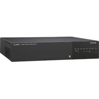
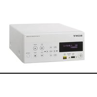

- VIDEOCASSETTE RECORDER
- UVW-1800/1800P
- OPERATING INSTRUCTIONS PAGE I (E)
- WARNING
- TO PREVENT FIRE OR SHOCK HAZARD, DO NOT EXPOSE THE UNIT TO RAIN OR MOISTURE
- CAUTION
- FOR THE CUSTOMERS IN USA
- FOR THE CUSTOMERS IN CANADA
- FOR THE CUSTOMERS IN THE UNITED KINGDOM
- THIS APPARATUS MUST BE EARTHED
- IMPORTANT
- CONTENTS
- CHAPTER 7 MENUS
- CHAPTER 8 MAINTENANCE
- CHAPTER 9 OPERATIONAL PROBLEMS
- APPENDIXES
- USABLE CASSETTE TAPES (SEE PAGE 3-3(E))
- REFERENCE VIDEO INPUT (SEE PAGE 3-5(E))
- INPUT VIDEO SIGNAL TYPE SELECTION (SEE PAGE 4-5(E))
- SETTING THE CASSETTE RECORD-INHIBIT PLUG (SEE PAGE 3-4(E))
- CONTROLLING TAPE TRANSPORT REMOTELY (SEE PAGE 7-3(E))
- STORING IN A RACK
- CHAPTER 1 OVERVIEW
- BETACAM SP FORMAT
- EXCELLENT VIDEO AND AUDIO CHARACTERISTICS
- COMPATIBILITY WITH OTHER BETACAM SP VTRS
- FULL RANGE OF RECORDING AND PLAYBACK FUNCTIONS
- BUILT-IN TIME CODE GENERATOR AND READER
- BUILT-IN TIME BASE CORRECTOR (TBC)
- MICROPROCESSOR SERVO SYSTEM
- AUDIO NOISE REDUCTION
- OTHER FEATURES
- COMPACT, POWER-SAVING DESIGN
- MENU-BASED SET-UP SYSTEM
- REMOTE CONTROL FUNCTION
- DIGITAL HOURS METER
- SUPERIMPOSED TEXT OUTPUT
- S-VIDEO CONNECTORS
- SELF-DIAGNOSIS FUNCTIONS
- ALARM INDICATIONS
- CHAPTER 2 IDENTIFICATION OF PARTS AND CONTROLS
- FRONT PANEL
- REAR PANEL
- VIDEO INPUTS
- SUBSIDIARY CONTROL PANEL
- NOTE
- POWER, TIME CODE AND CONTROL SIGNALS
- CHAPTER 3 PREPARATIONS
- BEFORE USE
- SAFETY NOTES
- POWER SUPPLY
- DO NOT DISMANTLE THE UNIT
- DO NOT DROP FOREIGN OBJECTS INTO THE CASING
- IN THE EVENT OF A MALFUNCTION
- NOTES ON OPERATION
- OPERATION AND STORAGE LOCATIONS
- OPERATE THE UNIT IN A HORIZONTAL POSITION
- AVOID VIOLENT IMPACTS
- DO NOT OBSTRUCT VENTILATION OPENINGS
- CARE
- SHIPPING
- CASSETTES
- CASSETTES WHICH CAN BE USED
- INSERTING AND EJECTING A CASSETTE
- INSERTING A CASSETTE
- REMOVING SLACK IN THE TAPE
- NO DOUBLE INSERTION OF CASSETTES
- EJECTING THE CASSETTE
- RECORD INHIBIT FUNCTION
- REFERENCE VIDEO SIGNALS
- CHAPTER 4 RECORDING AND PLAYBACK
- PLAYBACK OPERATION
- PREPARATION FOR PLAYBACK
- TO STOP PLAYBACK
- IF THE TAPE REACHES THE END DURING PLAYBACK
- ADJUSTING THE AUDIO PLAYBACK VOLUME
- SIMPLE SEARCH FUNCTION
- RECORDING OPERATION
- PREPARATION FOR RECORDING
- CB
- SWITCH AND CONTROL SETTINGS
- TO STOP RECORDING
- SELECTING THE INFORMATION DISPLAYED AND THE CHARACTER TYPE AND POSITION OF THE INDICATIONS
- TYPE OF TIME DATA
- SUPERIMPOSED TEXT INFORMATION
- DROP-FRAME INDICATION FOR TIME CODE READER (ONUVW-1800ONLY)
- DROP-FRAME INDICATION FOR TIME CODE GENERATOR (ON UVW-1800 ONLY)
- CHAPTER 5 EDITING
- CUT EDITING
- MONITORING THE VIDEO SIGNALS
- REFERENCE VIDEO SIGNAL AND EDITOR CONNECTIONS
- VIDEO AND AUDIO SIGNAL CONNECTIONS
- A/B ROLL EDITING
- MONITORING THE AUDIO AND VIDEO SIGNALS
- PHASE ADJUSTMENTS
- PHASE ADJUSTMENT PROCEDURE
- CHAPTER 6 TIME DATA
- DISPLAYING TIME DATA
- ON THE TIME COUNTER DISPLAY
- RESETTING THE CTL DATA DISPLAYED
- ON THE MONITOR SCREEN
- SETTINGS FOR LONGITUDINAL TIME CODE AND USER BITS
- SWITCH AND MENU SETTINGS
- INTERNAL TIME CODE GENERATOR RUNNING MODES
- PRESETTING THE TIME DATA VALUE TO REFLECT REAL TIME
- SYNCHRONIZING THE INTERNAL TIME CODE GENERATOR WITH AN EXTERNAL TIME CODE GENERATOR
- CONNECTIONS AND SWITCH SETTINGS
- CHECKING THE INTERNAL TIME CODE GENERATOR COUNTING
- MENU ORGANIZATION
- HIERARCHICAL STRUCTURE
- MENU SCREENS
- MENU OPERATIONS
- BUTTONS USED TO CHANGE THE SETTING
- OPERATION SEQUENCE
- DISPLAYING THE EXTENDED MENUS
- PRESS THE MENU BUTTON
- PRESS THE SET (YES) BUTTON
- NOTES
- CHANGING THE "NEXT MODE" SETTING
- PRESS THE ↑ BUTTON TO SELECT "TAPE PROTECTION
- RETURNING MENU SETTINGS TO THE FACTORY DEFAULT
- RETURNING A SPECIFIC MENU SETTING TO ITS FACTORY DEFAULT
- RETURNING ALL MENU SETTINGS TO THE FACTORY DEFAULT
- CONDENSATION
- IF MOISTURE CONDENSES ON THE HEAD-DRUM WHILE THE UNIT IS OPERATING
- IF THE CONDENSATION WARNING APPEARS IMMEDIATELY AFTER POWERING ON
- REGULAR CHECKS AND MAINTENANCE
- DIGITAL HOURS METER INDICATIONS
- T1: OPERATION
- T2: DRUM ROTATION
- T3: TAPE RUNNING
- CT: THREADING
- DISPLAYING THE DIGITAL HOURS METER
- MONITOR DISPLAY
- TIME COUNTER DISPLAY
- ENDING THE DIGITAL HOURS METER DISPLAY
- RESETTING THE TRIP VALUES
- HEAD CLEANING
- CLEANING PROCEDURE
- ALARM MESSAGES
- TROUBLE-SHOOTING CHART
- SPECIFICATION
- GENERAL
- TAPE TRANSPORT SYSTEM
- VIDEO SYSTEM
- AUDIO SYSTEM
- PROCESSOR ADJUSTMENT RANGE
- MAIN UNIT (UVW-1800/1800P)
- WITH BVR-50/50P TBC REMOTE CONTROL UNIT CONNECTED
- INPUT CONNECTORS
- VIDEO INPUT
- OUTPUT CONNECTORS
- HEADPHONES
- REMOTE CONNECTORS
- SUPPLIED ACCESSORIES
- OPTIONAL ACCESSORIES
- GLOSSARY
- A/B ROLL EDIT
- B-Y SIGNAL
- BRIDGING CONNECTION
- CAPSTAN
- CHROMINANCE SIGNAL
- COLOR FRAME
- COLOR FRAMING
- COMPONENT SIGNAL
- COMPOSITE SIGNAL
- CTL
- DROP FRAME MODE
- EE MODE
- EXTERNAL SYNCHRONIZATION
- IRE
- LNG RECORDING
- LTC
- LUMINANCE SIGNAL
- METAL TAPE
- MOISTURE CONDENSATION
- NON-DROP-FRAME MODE
- OXIDE TAPE
- R-Y SIGNAL
- REFERENCE VIDEO SIGNAL
- SMPTE
- S/N RATIO
- SEARCH MODE
- SERVO LOCK
- SUPERIMPOSE
- S-VIDEO INPUT CONNECTOR
- SYNC SIGNAL
- TBC
- TIME CODE
- TRACKING
- USER BITS
- V-BLANKING
- VBS
- VITC
- INDEX
- A
- B
- C
- D
- E
- F
- P
- R
- S
- T
Brand : SONY
Model : UVW-1800P
Category : VCR