
DUR141Z - String Trimmer MAKITA - Free user manual and instructions
Find the device manual for free DUR141Z MAKITA in PDF.


| Product Type | Cordless Grass Trimmer |
| Brand | Makita |
| Model | DUR141Z |
| Battery Voltage | 18 V |
| Battery Type | Lithium-ion (sold separately) |
| Cutting Diameter | 30 cm |
| Cutting Line Diameter | 2 mm |
| Total Length | 150 cm (telescopic) |
| Weight (without battery) | 2.8 kg |
| Noise Level | 80 dB(A) |
| Vibration Level | 2.5 m/s² |
| Head Type | Rotary, top loading |
| Cutting System | Nylon line |
| Power Source | Makita 18 V battery (sold separately) |
| Charge Time (4 Ah battery) | Approximately 45 minutes |
| Runtime (4 Ah battery) | Approximately 30 minutes |
| Protection | Double insulation |
| Features | Telescopic handle, adjustable grip, blade guard |
| Maintenance and Cleaning | Clean after each use, check line, lubricate moving parts |
| Safety | Wear goggles and gloves, do not use in rain |
| Spare Parts and Repairability | Available: cutting heads, line, batteries, chargers |
Frequently Asked Questions - DUR141Z MAKITA
User questions about DUR141Z MAKITA
0 question about this device. Answer the ones you know or ask your own.
Ask a new question about this device
Download the instructions for your String Trimmer in PDF format for free! Find your manual DUR141Z - MAKITA and take your electronic device back in hand. On this page are published all the documents necessary for the use of your device. DUR141Z by MAKITA.
USER MANUAL DUR141Z MAKITA
GB Cordless String Trimmer Instruction manual
1 010820 2 010821
3 012858
4 013641

5 012391 6 012128


7 015659 8 012397

9 012441 10 012396

11 012404 12 012394
13 012393 14 012408

15 012409 16 012440


17 012412 18 012413
19 012414 20 012415
21 012416 22 012417


23 012395 24 012399


25 012400 26 012401


27 012402 28 012403
29 012406 30 012405

31 012407 32 012398

ENGLISH (Original instructions)
Explanation of general view
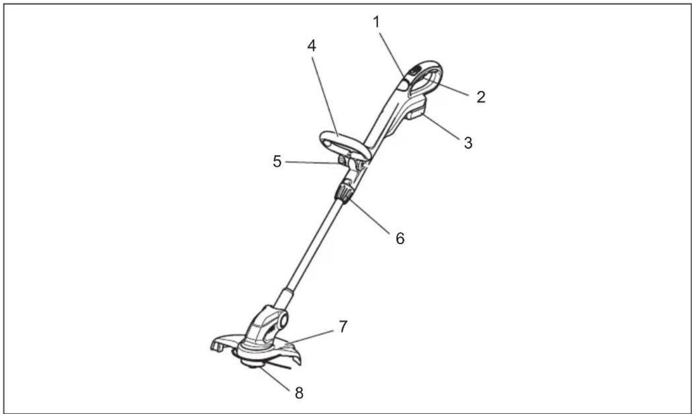
| 1. Indication lamp | 12. Indicator lamps | 22. Spring |
| 2. Switch trigger | 13. Check button | 23. Spool holder |
| 3. Battery cartridge | 14. Lock-off button | 24. Nylon cord |
| 4. Front grip | 15. Shaft | 25. Retainer for nylon cord end |
| 5. Clamping nut | 16. Grip | 26. Spool |
| 6. Lock grip | 17. Hex bolt | 27. Shoulder strap |
| 7. Guard | 18. Screws | 28. Hook |
| 8. Nylon cutting head | 19. Cutter cover | 29. Motor housing |
| 9. Red indicator | 20. Nylon cord eyehole | 30. Lock button |
| 10. Button | 21. Notch of the nylon cutting head installation port | |
| 11. Star marking |
SPECIFICATIONS
| Model DUR141 DUR181 | ||
| No load speed 6,000 min | -1 | 7,800 min-1 |
| Overall length 1,229 mm - 1,433 mm | 1,229 mm - 1,433 mm | |
| Cutting diameter with nylon cutting head 260 mm 260 mm | ||
| Nylon cord diameter | 1.65 mm | 1.65 mm |
| Net weight | 2.6 - 2.9 kg | 2.6 - 3.0 kg |
| Rated voltage | D.C. 14.4 V | D.C. 18 V |
- Due to our continuing program of research and development, the specifications herein are subject to change without notice.
- Specifications may differ from country to country.
- The weight may differ depending on the attachment(s), including the battery cartridge. The lightest and heaviest combination, according to EPTA-Procedure 01/2014, are shown in the table.
Applicable battery cartridge and charger
| Battery cartridge | D.C.14.4 V Model | BL1415N/BL1430B/BL1440/BL1460B |
| D.C.18 V Model | BL1815N/BL1820B/BL1830B/BL1840B/BL1850B/BL1860B | |
| Charger | DC18RC/DC18RD/DC18RE/DC18SD/DC18SE/DC18SF/DC18SH | |
• Some of the battery cartridges and chargers listed above may not be available depending on your region of residence.
WARNING:
- Only use the battery cartridges and chargers listed above. Use of any other battery cartridges and chargers may cause injury and/or fire.
Symbols
END017-5
The following show the symbols used for the equipment. Be sure that you understand their meaning before use.

..... Take particular care and attention.

..... Read instruction manual.

Danger; be aware of thrown objects.

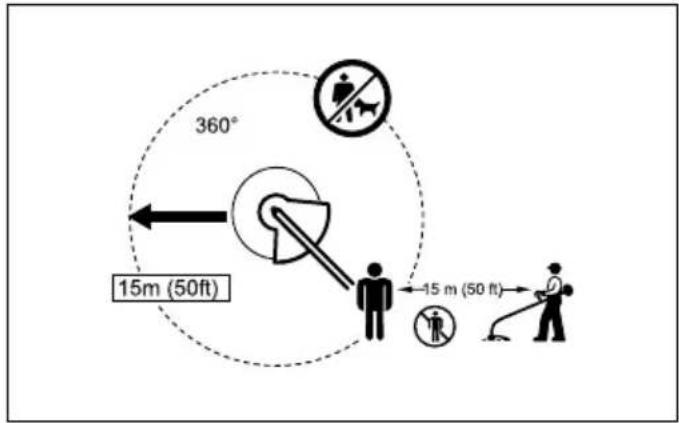
The distance between the tool and bystanders must be at least 15 m.

Keep bystanders away.
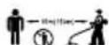
Keep distance at least 15 m.

...... Avoid kickback.

...... Wear safety glasses.

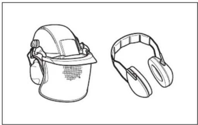
...... Wear ear protection.

......Wear a helmet, goggles and ear protection.

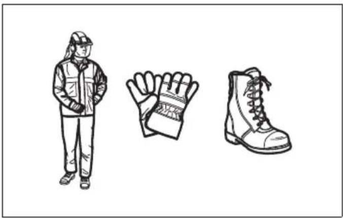
...... Wear protective gloves.

...... Wear sturdy boots with nonslip soles. Steeltoed safety boots are recommended.

...... Do not expose to moisture.

Ni-MH Li-ion
Only for EU countries
Due to the presence of hazardous components in the equipment, waste electrical and electronic equipment, accumulators and batteries may have a negative impact on the environment and human health.
Do not dispose of electrical and electronic appliances or batteries with household waste!
In accordance with the European Directive on waste electrical and electronic equipment and on accumulators and batteries and waste accumulators and batteries, as well as their adaptation to national law, waste electrical equipment, batteries and accumulators should be stored separately and delivered to a separate collection point for municipal waste, operating in accordance with the regulations on environmental protection.
This is indicated by the symbol of the crossed-out wheeled bin placed on the equipment.

Guaranteed sound power level according to EU Outdoor Noise Directive.

Sound power level according to Australia NSW Noise Control Regulation
IMPORTANT SAFETY INSTRUCTIONS
GEB092-5

WARNING! Read all safety warnings and all tructions. Failure to follow the warnings and tructions may result in electric shock, fire and/or ous injury.
Save all warnings and instructions for future reference.
- Be familiar with the controls and proper use of the equipment.
- Cutting elements continue to rotate after the motor is switched off.
- Never allow children or people unfamiliar with the instructions to use the machine.
- Stop using the machine while people, especially children, or pets are nearby.
- Only use the machine in daylight or good artificial light.
- Before using the machine and after any impact, check for signs of wear or damage and repair as necessary.
- Take care against injury from any device fitted for trimming the filament line length. After extending
new cutter line always return the machine to its normal operating position before switching on.
-
Never fit metal cutting elements.
-
This appliance is not intended for use by persons (including children) with reduced physical, sensory or mental capabilities, or lack of experience and knowledge, unless they have been given supervision or instruction concerning use of the appliance by a person responsible for their safety. Children should be supervised to ensure that they do not play with the appliance.
-
Use the tool with the utmost care and attention.
-
Operate the tool only if you are in good physical condition. Perform all work calmly and carefully. Use common sense and keep in mind that the operator or user is responsible for accidents or hazards occurring to other people or their property.
-
Never operate the tool when tired, feeling ill or under the influence of alcohol or drugs.
-
The tool should be switched off immediately if it shows any signs of unusual operation.
Intended use of the tool
- Use right tool. The cordless string trimmer is only intended for cutting grass, light weeds. It should not be used for any other purpose such as hedge cutting as this may cause injury.
Personal protective equipment (Fig. 1 & 2)
- Dress Properly. The clothing worn should be functional and appropriate, i.e. it should be tight-fitting but not cause hindrance. Do not wear either jewelry or clothing which could become entangled with high grass. Wear protective hair covering to contain long hair.
- When using the tool, always wear sturdy shoes with a non-slip sole. This protects against injuries and ensures a good footing.
- Wear protective glasses or goggles.
Electrical and battery safety
- Avoid dangerous environment. Don't use the tool in damp or wet locations or expose it to rain. Water entering the tool will increase the risk of electric shock.
- Recharge only with the charger specified by the manufacturer. A charger that is suitable for one type of battery pack may create a risk of fire when used with another battery pack.
- Use power tools only with specifically designated battery packs. Use of any other battery packs may create a risk of injury and fire.
- Do not dispose of the battery(ies) in a fire. The cell may explode. Check with local codes for possible special disposal instructions.
- Do not open or mutilate the battery(ies). Released electrolyte is corrosive and may cause damage to the eyes or skin. It may be toxic if swallowed.
Starting up the tool (Fig. 3)
-
Make sure that there are no children or other people within a working range of 15 meters (50 ft), also pay attention to any animals in the working vicinity. Otherwise stop using the tool.
-
Before use always check that the tool is safe for operation. Check the security of the cutting tool and the guard and the switch trigger/lever for easy and proper action. Check for clean and dry handles and test the on/off function of the switch.
- Check damaged parts before further use of the tool. A guard or other part that is damaged should be carefully checked to determine that it will operate properly and perform its intended function. Check for alignment of moving parts, binding of moving parts, breakage of parts, mounting, and any other condition that may affect its operation. A guard or other part that is damaged should be properly repaired or replaced by our authorized service center unless indicated elsewhere in this manual.
- Switch on the motor only when hands and feet are away from the cutting tool.
- Before starting make sure that the cutting tool has no contact with hard objects such as branches, stones etc. as the cutting tool will revolve when starting.
Method of operation
- Never operate the machine with damaged guards or without the guards in place.
- Only use the tool in good light and visibility. During the winter season beware of slippery or wet areas, ice and snow (risk of slipping). Always ensure a safe footing.
- Take care against injury to feet and hands from the cutting tool.
- Keep hands and feet away from the cutting means at all times and especially when switching on the motor.
- Never cut above waist height.
- Never stand on a ladder and run the tool.
- Never work on unstable surfaces.
- Don't overreach. Keep proper footing and balance at all times.
- Always be sure of your footing on slopes.
- Walk, never run.
- Remove sand, stones, nails etc. found within the working range. Foreign particles may damage the cutting tool and can cause to be thrown away, resulting in a serious injury.
- Never touch moving hazardous parts before the machine is disconnected from the mains and the moving hazardous parts have come to a complete stop.
- Should the cutting tool hit stones or other hard objects, immediately switch off the motor and inspect the cutting tool.
- Before commencing cutting, the cutting tool must have reached full working speed.
- During operation always hold the tool with both hands. Never hold the tool with one hand during use. Always ensure a safe footing.
- All protective equipment such as guards supplied with the tool must be used during operation.
-
Except in case of emergency, never drop or cast the tool to the ground or this may severely damage the tool.
-
Never drag the tool on the ground when moving from place to place, the tool may become damaged if moved in this manner.
- Always remove the battery cartridge from the tool:
– whenever leaving the tool unattended;
– before clearing a blockage;
– before checking, cleaning or working on the tool;
– before making any adjustments, changing accessories or storing;
- whenever the tool starts vibrating unusually;
- whenever transporting the tool.
- Don't force the tool. It will do the job better and with less likelihood of a risk of injury at the rate for which it was designed.
Maintenance instructions
- The condition of the cutting tool, protective devices must be checked before commencing work.
- Turn off the motor and remove the battery cartridge before carrying out maintenance, replacing the cutting tool and cleaning the tool.
- After use, disconnect the battery cartridge from the tool and check for damage.
- Check for loose fasteners and damaged parts such as nearly halfway cut-off state in the cutting tool.
- When not in use store the equipment in a dry location that is locked up or out of children's reach.
- Use only the manufacturer's recommended replacement parts and accessories.
- Always ensure that ventilation openings are kept clear of debris.
- Inspect and maintain the tool regularly, especially before/after use. Have the tool repaired only by our authorized service center.
- Keep handles dry, clean and free from oil and grease.
SAVE THESE INSTRUCTIONS.
WARNING:
DO NOT let comfort or familiarity with product (gained from repeated use) replace strict adherence to safety rules for the subject product. MISUSE or failure to follow the safety rules stated in this instruction manual may cause serious personal injury.
Important safety instructions for battery cartridge ENC007
ENC007-17
- Before using battery cartridge, read all instructions and cautionary markings on (1) battery charger, (2) battery, and (3) product using battery.
- Do not disassemble or tamper with the battery cartridge. It may result in a fire, excessive heat, or explosion.
-
If operating time has become excessively shorter, stop operating immediately. It may result in a risk of overheating, possible burns and even an explosion.
-
If electrolyte gets into your eyes, rinse them out with clear water and seek medical attention right away. It may result in loss of your eyesight.
-
Do not short the battery cartridge:
(1) Do not touch the terminals with any conductive material.
(2) Avoid storing battery cartridge in a container with other metal objects such as nails, coins, etc.
(3) Do not expose battery cartridge to water or rain.
A battery short can cause a large current flow, overheating, possible burns and even a breakdown.
-
Do not store and use the tool and battery cartridge in locations where the temperature may reach or exceed 50 °C (122 °F).
-
Do not incinerate the battery cartridge even if it is severely damaged or is completely worn out. The battery cartridge can explode in a fire.
-
Do not nail, cut, crush, throw, drop the battery cartridge, or hit against a hard object to the battery cartridge. Such conduct may result in a fire, excessive heat, or explosion.
-
Do not use a damaged battery.
-
The contained lithium-ion batteries are subject to the Dangerous Goods Legislation requirements. For commercial transports e.g. by third parties, forwarding agents, special requirement on packaging and labeling must be observed. For preparation of the item being shipped, consulting an expert for hazardous material is required. Please also observe possibly more detailed national regulations.
Tape or mask off open contacts and pack up the battery in such a manner that it cannot move around in the packaging.
-
When disposing the battery cartridge, remove it from the tool and dispose of it in a safe place. Follow your local regulations relating to disposal of battery.
-
Use the batteries only with the products specified by Makita. Installing the batteries to non-compliant products may result in a fire, excessive heat, explosion, or leak of electrolyte.
-
If the tool is not used for a long period of time, the battery must be removed from the tool.
-
During and after use, the battery cartridge may take on heat which can cause burns or low temperature burns. Pay attention to the handling of hot battery cartridges.
-
Do not touch the terminal of the tool immediately after use as it may get hot enough to cause burns.
-
Do not allow chips, dust, or soil stuck into the terminals, holes, and grooves of the battery cartridge. It may cause heating, catching fire, burst and malfunction of the tool or battery cartridge, resulting in burns or personal injury.
-
Unless the tool supports the use near high-voltage electrical power lines, do not use the battery cartridge near high-voltage electrical power lines. It may result in a malfunction or breakdown of the tool or battery cartridge.
-
Keep the battery away from children.
SAVE THESE INSTRUCTIONS.
CAUTION: Only use genuine Makita batteries. Use of non-genuine Makita batteries, or batteries that have been altered, may result in the battery bursting causing fires, personal injury and damage. It will also void the Makita warranty for the Makita tool and charger.
Tips for maintaining maximum battery life
- Charge the battery cartridge before completely discharged. Always stop tool operation and charge the battery cartridge when you notice less tool power.
- Never recharge a fully charged battery cartridge. Overcharging shortens the battery service life.
- Charge the battery cartridge with room temperature at 10 °C - 40 °C (50 °F - 104 °F). Let a hot battery cartridge cool down before charging it.
- When not using the battery cartridge, remove it from the tool or the charger.
- Charge the battery cartridge if you do not use it for a long period (more than six months).
PARTS DESCRIPTION (Fig. 4)
FUNCTIONAL DESCRIPTION
WARNING:
• Always be sure that the tool is switched off and battery cartridge is removed before adjusting or checking function on the tool. Failure to switch off and remove the battery cartridge may result in serious personal injury from accidental start-up.
Installing or removing battery cartridge (Fig. 5)
CAUTION:
- Always switch off the tool before installing or removing of the battery cartridge.
- Hold the tool and the battery cartridge firmly when installing or removing battery cartridge. Failure to hold the tool and the battery cartridge firmly may cause them to slip off your hands and result in damage to the tool and battery cartridge and a personal injury.
To remove the battery cartridge, slide it from the tool while sliding the button on the front of the cartridge.
To install the battery cartridge, align the tongue on the battery cartridge with the groove in the housing and slip it into place. Insert it all the way until it locks in place with a little click. If you can see the red indicator on the upper side of the button, it is not locked completely.
CAUTION:
• Always install the battery cartridge fully until the red indicator cannot be seen. If not, it may accidentally fall out of the tool, causing injury to you or someone around you.
- Do not install the battery cartridge forcibly. If the cartridge does not slide in easily, it is not being inserted correctly.
Battery protection system (Lithium-ion battery with star marking) (Fig. 6)
Lithium-ion batteries with a star marking are equipped with a protection system. This system automatically cuts off power to the tool to extend battery life.
The tool will automatically stop during operation if the tool and/or battery are placed under one of the following conditions:
- Overloaded:
The tool is operated in a manner that causes it to draw an abnormally high current.
In this situation, release the switch trigger on the tool and stop the application that caused the tool to become overloaded. Then pull the switch trigger again to restart.
If the tool does not start, the battery is overheated. In this situation, let the battery cool before pulling the switch trigger again.
- Low battery voltage:
The remaining battery capacity is too low and the tool will not operate. In this situation, remove and recharge the battery.
Indicating the remaining battery capacity
Only for battery cartridges with the indicator (Fig. 7)
Press the check button on the battery cartridge to indicate the remaining battery capacity. The indicator lamps light up for a few seconds.
| Indicator lamps | Remaining capacity | ||
| Lighted Off Blinking | |||
| 75% to 100% | |||
| 50% to 75% | |||
| 25% to 50% | |||
| 0% to 25% | |||
| Charge the battery. | |||
| The battery may have malfunctioned. | |||
015658
NOTE:
- Depending on the conditions of use and the ambient temperature, the indication may differ slightly from the actual capacity.
- The first (far left) indicator lamp will blink when the battery protection system works.
Power switch action
WARNING:
- Before inserting the battery cartridge in the tool, always check to see that the switch trigger actuates properly and returns to the "OFF"
position when released. Do not pull the switch trigger hard without pressing in the lock-off button.
This can cause switch breakage. Operating a tool with a switch that does not actuate properly can lead to loss of control and serious personal injury.
To prevent the switch trigger from being accidentally pulled, a lock-off button is provided.
To start the tool, move the lock-off button forward and pull the switch trigger. Release the switch trigger to stop.
(Fig. 8)
Indication lamp (Fig. 9)
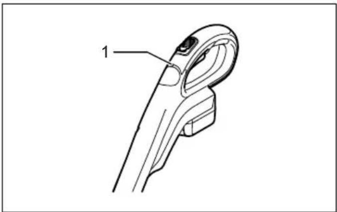
Running the tool allows the indication lamp to show the battery cartridge capacity status.
When the tool is also overloaded and has stopped during operation, the lamp lights up in red.
Refer to the following table for the status and action to be taken for the indication lamp.
| Indication lamp Status Action | to be taken | |
| The lamp blinks in red. This indicates the | e appropriate time to replace the battery cartridge when the battery power becomes low. | Recharge the battery cartridge as soon as possible. |
| The lamp lights up in red. (Note 1) | This function works when the battery power is almost used up. At this time, tool stops immediately. | Recharge the battery cartridge. |
| The lamp lights up in red. (Note 1) | Autostop due to overload. Turn off the tool. | |
Note 1: The time at which the indication lamp lights up varies by the temperature around the work area and the battery cartridge conditions.
012443
Adjusting the shaft length

WARNING:
- Before adjusting the shaft length, release the switch trigger and remove the battery cartridge from the string trimmer. Failure to release the trigger and removing the battery cartridge may cause a personal injury.
To adjust the length of the shaft, turn the grip counterclockwise until the shaft is unlocked and pull out or push in to the desired length. (Fig. 10)
Nylon cutting head
NOTICE:
- The bump feed will not operate properly if the nylon cutting head is not rotating.
The nylon cutting head is a single string trimmer head provided with a bump & feed mechanism.
To cause the nylon cord to feed out, the cutting head should be bumped against the ground while the tool is running. As the nylon cord is feeding out it will automatically be cut to the proper length by the cutter on the guard. (Fig. 11)
NOTE:
- If the nylon cord does not feed out while bumping the head, rewind/replace the nylon cord by following the procedures described under “Installing or removing the nylon cutting head” and “Winding a new nylon cord on the spool.”
- Do not bump the tool to the concrete or asphalt surface. Bumping to this kind of objects may cause the tool damage.
ASSEMBLY

WARNING:
• Always be sure that the tool is switched off and battery cartridge is removed before carrying out any work on the tool. Failure to switch off and remove the battery cartridge may result in serious personal injury from accidental start-up.
- Never start the tool unless it is completely assembled. Operation of the tool in a partially assembled state may result in serious personal injury from accidental start-up.
Installing the front grip (Fig. 12)
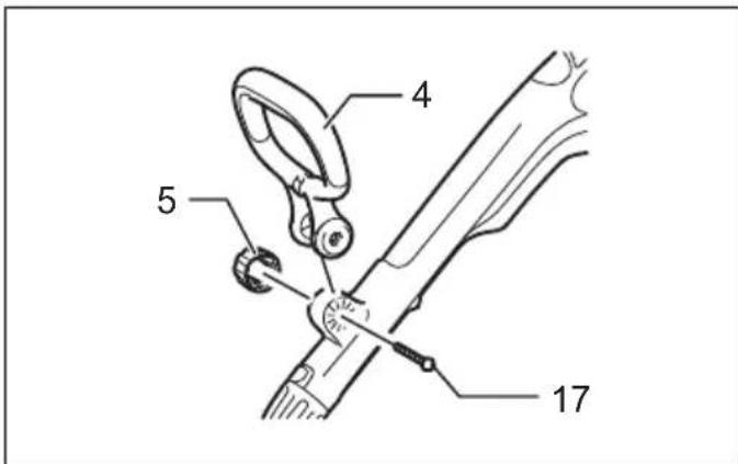
Put the front grip on the front grip holder and secure it with a hex bolt and the clamping nut provided with the string trimmer as shown in the figure. At this time, the hex bolt
needs to be installed from the side in which the hex bolt lock port is located and the clamping nut needs to be installed from the opposite side.
NOTE:
- The front grip has a edge-to-edge cut slit in its mounting area. Using this slit allows you to easily install the front grip on the front grip holder.
The front grip angle is adjustable. To adjust the front grip angle, loosen the claming nut, set the front grip at an proper angle according to your work and then tighten the nut clockwise firmly.
Installing the guard

CAUTION:
- While installing the guard, be careful not to contact the nylon cord cutter provided on the guard.
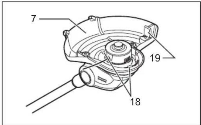
Contact with the cutter could result in personal injury. Mount the guard by fitting it on to the motor housing so that the nylon cord is not pinched between the guard and the motor housing, and then secure it with two screws. Before starting the trimmer, take away the cutter cover from the cord cutter. (Fig. 13)
Installing or removing the nylon cutting head

WARNING:
- Before installing or removing the nylon cutting head (both spool cover and spool, and hereafter called this way), make sure that the tool is switched off and the battery cartridge is removed from the tool. Failure to switch off the tool and remove the battery cartridge may cause a personal injury.

CAUTION:
- While installing or removing the nylon cutting head, be careful not to contact the nylon cord cutter provided on the guard. Contact with the cutter could result in personal injury.
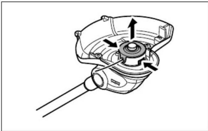
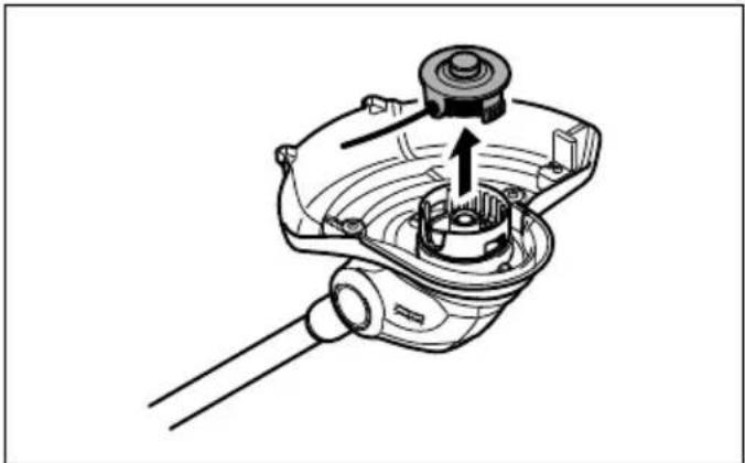
To remove the nylon cutting head (spool and spool cover) from the string trimmer, press in the latches forcefully on both sides of the spool cover and raise it. (Fig. 14 & 15)
NOTICE:
- Make sure that the spring is installed inside the spool holder.
To install a cord-newly-wound nylon cutting head (spool and spool cover) on the string trimmer, align the nylon cord eyehole with the notch of the nylon cutting head
installation port on the trimmer and then press in it until a click is heard. (Fig. 16)
Winding a new nylon cord on the spool
Remove the spool from the spool cover and take off the remaining used nylon cord from the spool. (Fig. 17)
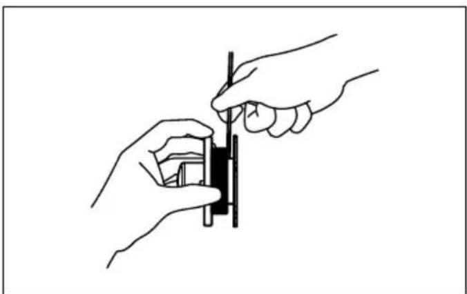
Insert a nylon cord to the retainer shown in the figure. (Fig. 18)
Wind it tightly flat around the spool in the direction of arrow on the spool so that the wound nylon cord surface appears uniform over the winding area. (Fig. 19)
Temporarily fix a nylon cord at the notch shown in the figure. (Fig. 20)
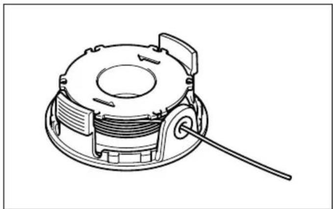
Bring the nylon cord through the nylon cord eyehole in the spool cover. (Fig. 21)
After installing the nylon cutting head, make sure that the nylon cord comes out by pressing the spool and pulling the nylon cord. (Fig. 22)
OPERATION
Attachment of shoulder strap
CAUTION:
When you use the tool in combination of the backpack-type power supply such as portable power pack, do not use the shoulder harness included in the tool package, but use the hanging band recommended by Makita.
If you put on the shoulder harness included in the tool package and the shoulder harness of the backpack-type power supply at the same time, removing the tool or backpack-type power supply is difficult in case of an emergency, and it may cause an accident or injury. For the recommended hanging band, ask Makita Authorized Service Centers. (Fig. 23)
Hook the shoulder strap in a hole in the front grip.
Operation
CAUTION:
- Do not cut high grass at a time. Cutting high grass at a time near the root may cause the trimmer motor spindle to be entangled by grass which leads to the motor under overload, resulting in damage to the trimmer.
CAUTION:
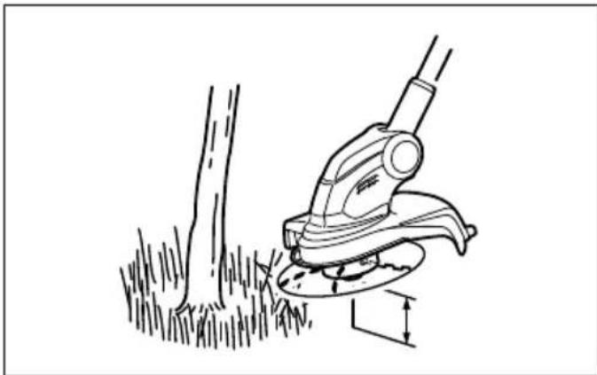
- Use the trimmer without getting the spool into a contact with the ground surface. Using the spool contacting the ground surface may cause the motor under overload resulting in damage to the trimmer. (Fig. 24 & 25)
CAUTION:
- Do not force the trimmer in densely growing grass. (Fig. 26)
CAUTION:
- Do not use the trimmer as if you dig out the ground with it. (Fig. 27)
Cutting the grass near a tree, concrete block, brick or garden stone (Fig. 28)
Hold the trimmer tilting at a level so that it does not contact the ground surface and cut the grass using the nylon cord tip like knocking the ground. In this work, smooth feeding out is needed because the nylon cord wears more quickly than usual.
NOTE:
- Getting the trimmer too close to a tree, concrete block, brick or garden stone or the like during performing the edging work or such similar cutting work may cause the nylon cord to be cut off halfway inside the spool cover. At this time, take the spool out of the spool cover and then set the nylon cord again properly by referring to the section titled “Installing or removing the nylon cutting head” and “Winding a new nylon cord on the spool”. Using the tip of the nylon cord during operation brings the best result of operation and therefore it is recommended to keep the tool more than 5 cm away from the tree, concrete block, brick or garden stone or the like.
Start the trimmer before getting close to the grass to be cut.
Cut the grass using the nylon cord tip by moving the trimmer from right to left and proceed slowly, keeping the trimmer tilted at the angle of about 30° in relation to the ground surface.
When cutting high grass, cut in layers always beginning from the top with each cut length short.
Using the tool as an edger
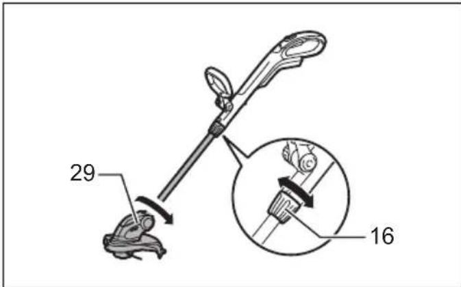
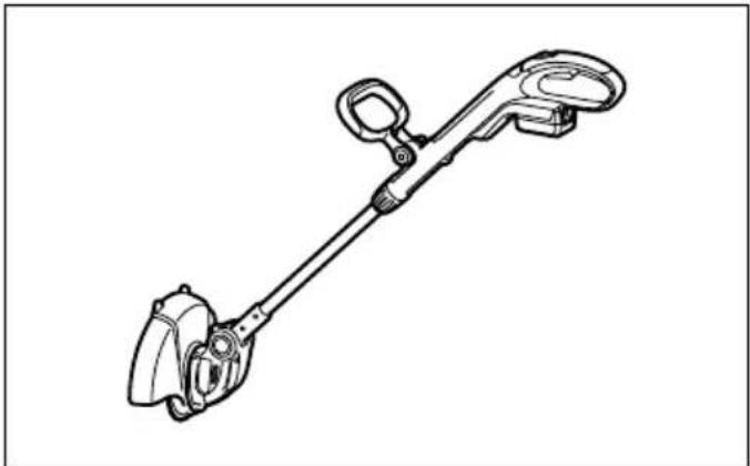
Using the tool as an edger allows the operator to cut along the edge of the concrete block, brick and the like. (Fig. 29) For using the tool as an edger, hold the shaft of the trimmer with one hand and turn the grip counter clockwise to loosen the shaft. Rotate the shaft with the motor housing 180° and tighten the grip clockwise until it locks.
(Fig. 30)
NOTE:
- Before rotating the shaft, it needs to be fully shortened or extended.
• After changing to the edger position, make sure that the motor housing and shaft are locked.
To obtain a good result of finish cutting, move parallel to the edge you are going to perform an edging work.
(Fig. 31)
Cutting the grass in a tight place or on a slope
WARNING:
- When cutting the grass on a slope, be careful of stones, grass and other foreign objects thrown from the cutting head area.
- When cutting the grass on a slope, make sure that you always keep a good and stable footing.
To ease the work in a tight place which restricts the height, such as cutting the grass under an outdoor wood deck and similars, push the lock button and then bend down the cutting head so that the shaft is parallel to the ground surface. Adjusting the cutting head angle properly in this way helps you cut the grass on a slope. (Fig. 32)
MAINTENANCE
WARNING:
- Always be sure that the tool is switched off and battery cartridge is removed before attempting to perform inspection or maintenance on the tool. Failure to switch off and remove the battery cartridge may result in serious personal injury from accidental start-up.
NOTICE:
Never use gasoline, benzine, thinner, alcohol or the like. Discoloration, deformation or cracks may result. To maintain product SAFETY and RELIABILITY, repairs, any other maintenance or adjustment should be performed by Makita Authorized Service Centers, always using Makita replacement parts.
OPTIONAL ACCESSORIES
CAUTION:
• These accessories or attachments are recommended for use with your Makita tool specified in this manual. The use of any other accessories or attachments might present a risk of injury to persons. Only use accessory or attachment for its stated purpose.
If you need any assistance for more details regarding these accessories, ask your local Makita Service Center.
- Nylon cutting head
- Nylon cords
- Shoulder strap
- Goggles
- Makita genuine battery and charger
NOTE:
- Some items in the list may be included in the tool package as standard accessories. They may differ from country to country.
Noise
ENG905-1
The typical A-weighted noise level determined according to EN786:
Model DUR141
Sound pressure level ( LpA ): 75 dB (A)
Sound power level ( LWA ): 83.7 dB (A)
Uncertainty (K): 2.5 dB (A)
The noise level under working may exceed 80 dB (A).
Model DUR181
Sound pressure level ( LpA ): 82 dB (A)
Sound power level ( LWA ): 88.5 dB (A)
Uncertainty (K): 2.5 dB (A)
ENG907-1
- The declared noise emission value(s) has been measured in accordance with a standard test method and may be used for comparing one tool with another.
- The declared noise emission value(s) may also be used in a preliminary assessment of exposure.
WARNING:
- Wear ear protection.
- The noise emission during actual use of the power tool can differ from the declared value(s) depending on the ways in which the tool is used especially what kind of workpiece is processed.
- Be sure to identify safety measures to protect the operator that are based on an estimation of exposure in the actual conditions of use (taking account of all parts of the operating cycle such as the times when the tool is switched off and when it is running idle in addition to the trigger time).
Vibration
ENG904-2
The vibration total value determined according to EN786: Vibration emission ( an ): 2.5 m/s 2 or less Uncertainty (K): 1.5 m/s 2
ENG901-2
- The declared vibration total value(s) has been measured in accordance with a standard test method and may be used for comparing one tool with another.
- The declared vibration total value(s) may also be used in a preliminary assessment of exposure.
WARNING:
- The vibration emission during actual use of the power tool can differ from the declared value(s) depending on the ways in which the tool is used especially what kind of workpiece is processed.
- Be sure to identify safety measures to protect the operator that are based on an estimation of exposure in the actual conditions of use (taking account of all parts of the operating cycle such as the times when the tool is switched off and when it is running idle in addition to the trigger time).
EC Declaration of Conformity For European countries only
The EC declaration of conformity is included as Annex A to this instruction manual.
WAARSCHUWING! Lees alle
| Akü | D.C. 14,4V Model | BL1415N/BL1430B/BL1440/BL1460B |
| D.C. 18V Model | BL1815N/BL1820B/BL1830B/BL1840B/BL1850B/BL1860B | |
| Şarj cihazı | DC18RC/DC18RD/DC18RE/DC18SD/DC18SE/DC18SF/DC18SH | |


- ENGLISH (ORIGINAL INSTRUCTIONS)
- APPLICABLE BATTERY CARTRIDGE AND CHARGER
- WARNING
- SYMBOLS
- IMPORTANT SAFETY INSTRUCTIONS
- SAVE ALL WARNINGS AND INSTRUCTIONS FOR FUTURE REFERENCE
- INTENDED USE OF THE TOOL
- PERSONAL PROTECTIVE EQUIPMENT (FIG. 1 & 2)
- ELECTRICAL AND BATTERY SAFETY
- STARTING UP THE TOOL (FIG. 3)
- METHOD OF OPERATION
- MAINTENANCE INSTRUCTIONS
- SAVE THESE INSTRUCTIONS
- IMPORTANT SAFETY INSTRUCTIONS FOR BATTERY CARTRIDGE ENC007
- TIPS FOR MAINTAINING MAXIMUM BATTERY LIFE
- PARTS DESCRIPTION (FIG. 4)
- FUNCTIONAL DESCRIPTION
- INSTALLING OR REMOVING BATTERY CARTRIDGE (FIG. 5)
- CAUTION
- BATTERY PROTECTION SYSTEM (LITHIUM-ION BATTERY WITH STAR MARKING) (FIG. 6)
- INDICATING THE REMAINING BATTERY CAPACITY
- ONLY FOR BATTERY CARTRIDGES WITH THE INDICATOR (FIG. 7)
- NOTE
- POWER SWITCH ACTION
- INDICATION LAMP (FIG. 9)
- ADJUSTING THE SHAFT LENGTH
- NYLON CUTTING HEAD
- NOTICE
- ASSEMBLY
- INSTALLING THE FRONT GRIP (FIG. 12)
- INSTALLING THE GUARD
- INSTALLING OR REMOVING THE NYLON CUTTING HEAD
- WINDING A NEW NYLON CORD ON THE SPOOL
- OPERATION
- ATTACHMENT OF SHOULDER STRAP
- CUTTING THE GRASS NEAR A TREE, CONCRETE BLOCK, BRICK OR GARDEN STONE (FIG. 28)
- USING THE TOOL AS AN EDGER
- (FIG. 30)
- (FIG. 31)
- CUTTING THE GRASS IN A TIGHT PLACE OR ON A SLOPE
- MAINTENANCE
- OPTIONAL ACCESSORIES
- NOISE
- MODEL DUR141
- MODEL DUR181
- VIBRATION
- EC DECLARATION OF CONFORMITY FOR EUROPEAN COUNTRIES ONLY
Brand : MAKITA
Model : DUR141Z
Category : String Trimmer