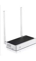
N300RT - Router Totolink - Free user manual and instructions
Find the device manual for free N300RT Totolink in PDF.


| Product Type | Wireless N300 Router |
| Wireless Standard | IEEE 802.11b/g/n |
| Maximum Wireless Speed | 300 Mbps |
| Frequency Band | 2.4 GHz |
| LAN Ports | 4 x 10/100 Mbps |
| WAN Port | 1 x 10/100 Mbps |
| Antennas | 2 x External 5 dBi |
| Power Supply | 5V DC, 1A |
| Dimensions (W x D x H) | 180 x 130 x 30 mm |
| Weight | 0.2 kg |
| Security | WEP, WPA/WPA2-PSK, WPA2-Enterprise, SPI Firewall |
| Management | Web-based GUI, WPS, QoS |
| Operating Temperature | 0°C to 40°C |
| Storage Temperature | -20°C to 70°C |
| Humidity | 10% to 90% non-condensing |
| Package Contents | Router, Power Adapter, Ethernet Cable, Quick Start Guide |
| Maintenance | Clean with a soft, dry cloth; avoid liquids |
Frequently Asked Questions - N300RT Totolink
User questions about N300RT Totolink
0 question about this device. Answer the ones you know or ask your own.
Ask a new question about this device
Download the instructions for your Router in PDF format for free! Find your manual N300RT - Totolink and take your electronic device back in hand. On this page are published all the documents necessary for the use of your device. N300RT by Totolink.
USER MANUAL N300RT Totolink
1. ABOUT THIS GUIDE......3
1.1 Navigation of the User's Guide....3
2. PRODUCT OVERVIEW....3
2.1 Introduction....3
2.2 Features .... 3
2.3 Panel Layout ....4
2.3.1 Front Panel 4
2.3.2 Rear Panel 5
3. HARDWARE INSTALLATION....6
3.1 Hardware Installation....6
3.2 Check the Installation....6
3.3 Set up the Computer ....6
4. CONNECTING TO INTERNET 8
4.1 Accessing Web page 8
4.2 Changing Password ......9
4.3 Setup Wizard....10
4.3.1 Router Mode 12
4.3.2 Wireless ISP Client Mode 17
4.3.3 Wireless Client Mode 18
4.3.4 Repeater Mode 19
4.3.5 Bridge with AP 21
4.3.6 Client Mode 22
4.4 Quick Setup....22
4.5 Status 24
4.4.1 System status....24
4.4.2 Statistics 25
4.4.3 System log 26
5. ADVANCED SETTINGS....27
5.1 TCP/IP Settings....27
5.1.1 LAN Interface 27
5.1.2 WAN Interface 29
5.1.2.1 PPPoE 30
5.1.2.2 PPTP 31
5.1.2.3 L2TP 32
5.1.3 Alias IP 33
5.1.4 VLAN Settings.... 33
5.2 Wireless....34
5.2.1 Basic Settings 35
5.2.2 Security Settings 39
5.2.3 Site Survey.... 39
5.2.4 WDS....39
5.2.5 Advanced Settings 40
5.2.6 Access Control 42
5.2.7 WPS Settings 42
5.2.8 Schedule 43
5.3 Route Setup 43
5.3.1 Static Route 43
5.3.2 Routing Table 45
5.4 Firewall 45
5.4.1 IP Filtering 46
5.4.2 Port Filtering.... 46
5.4.3 MAC Filtering 47
5.4.4 URL Filtering 47
5.4.5 Port Forwarding.... 48
5.4.6 DMZ 48
5.4.7 Denial-of-Service.... 49
5.4.8 NAT Mapping.... 50
5.5 Management....50
5.5.1 Upgrade Firmware 50
5.5.2 Save/Reload Setting 51
5.5.3 Web Login Password 51
5.5.4 TR-069 Config 52
5.5.5 Date and Time.... 53
5.5.6 Reboot Router 53
5.5.7 Reboot Schedule.... 53
All the photos and product specifications mentioned in this manual are for references only, as the upgrading of software and hardware. They are subject to change without notice. No part of the specifications may be reproduced in any form or by any means or used to make any derivative such as translation, transformation, or adaptation without permission from TOTOLINK. If you want to know more about our products information, please visit our website at http://www.totolink.net
Copyrights 2013 by TOTOLINK All rights reserved.
1. ABOUT THIS GUIDE
Thank you very much for purchasing this router. This guide will introduce the features of this router and tell you how to connect, use and configure the router to access Internet. Please follow the instructions in this guide to avoid affecting the router's performance by improper operation.
1.1 Navigation of the User's Guide
Product Overview: Describes the router's function and its features.
Hardware Installation: Describes the hardware installation and settings on user's computer.
Connecting to Internet: Tells you how to connect your computer to Internet successfully by the router.
Advanced Settings: Lists all technical functions including Wireless, TCP/IP Settings, Firewall and System of the router.
2. PRODUCT OVERVIEW
2.1 Introduction
This is a wireless router which integrates with internet-sharing router, 4-port switch and firewall all-in-one. It allows users to connect to Internet by DHCP/Static IP/PPPoE(dual access)/PPTP(dual access)/L2TP(dual access) and can deliver high speed wireless data rate. The VLAN function also makes amazing interactive entertainment experience of IPTV be achieved easily. Multiple encryptions including wireless LAN 64/128-bit WEP, WPA/WPA2 and WPA-mixed security are supported by the router. The IP, Port, URL and MAC address filtering function also makes it easy for user management. In view of the above, it will allow you to connect your network wirelessly in an easy and secure way better than ever. It is really a high performance and cost-effective solution for home and small offices.
2.2 Features
Complies with IEEE 802.11n and IEEE 802.11g/b standards for 2.4GHz Wireless LAN.
Supports DHCP, Static IP, PPPoE, PPTP and L2TP broadband functions and supports dual access.
Provides six operation modes: Wireless ISP Client Router, Wireless Client, Repeater, Router, Bridge with AP and Client.
- Connects to secure network easily and fast using WPS (one-button).
- Provides 64/128-bit WEP, WPA/WPA2 and WPA-Mixed security.
▶ VLAN function for IPTV or other internet services.
Supports IP, Port, MAC, URL filtering and Port Forwarding.
QoS function allocates network bandwidth reasonably.
Supports SSH Server function to ensure the security of remote login.
➢ Setup Wizard simplifies the basic settings of the router.
2.3 Panel Layout
2.3.1 Front Panel
The front panel of this router consists of 8 LEDs, which is designed to indicate connection status.
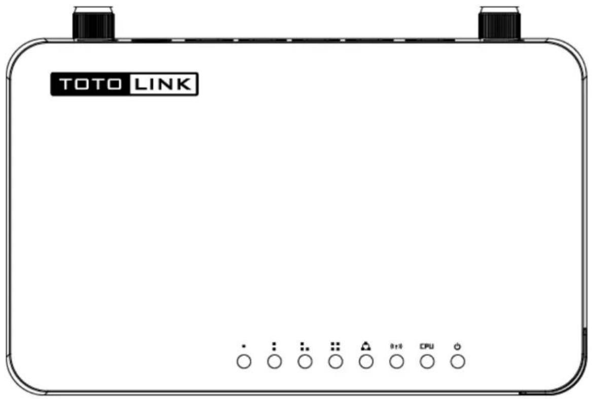
| POWER | This indicator lights blue when the router powered on, otherwise it is off. | |
| CPU | This indicator blinks blue when router powered on. | |
| WLAN | This indicator blinks blue when there are wireless devices connected and transmitting data to the router. | |
| WAN | On | When the WAN port is connected successfully the indicator lights blue. |
| Blink | During transmitting or receiving data through the WAN port the indicator blinks blue. | |
| Off | There is no device linked to the WAN port. | |
| 1/2/3/4 LAN | On | When the LAN port has a successful connection, the corresponding indicator lights blue. |
| Blink | During transmitting or receiving data through the LAN port the corresponding indicator blinks blue. | |
| Off | There is no device linked to the LAN port. | |
2.3.2 Rear Panel
The figure below shows the rear panel of this router.

| Power ON/OFF | Turn on or turn off the router by the switch. |
| DC IN | The Power socket is where you will connect the power adapter. |
| WAN | This port is where you will connect with the cable to access Internet. |
| 1/2/3/4 LAN | This port connects the router to local PC. |
| RST • WPS Button | The button is on the opposite of the rear panel. Press for about 2~3 seconds, the system LED indicator keep solid light, it means WPS working, while press for about 10 seconds, all LEDs blinks quickly, the device will restore to factory default settings. |
3. HARDWARE INSTALLATION
3.1 Hardware Installation
For those computers you wish to connect with Internet by this router, each of the computers must be properly connected with the router through provided UTP LAN Cables.
- Connect the provided UTP LAN cable to one of the router's LAN port.
- Connect the other end of the UTP LAN cable to your computer's LAN port.
- Connect the second UTP LAN cable to router's WAN port.
- Connect the other end of the UTP LAN cable to ADSL or Modem port.
- Plug the Power Adapter into the router and then into an outlet.
- Turn on your computer.
- Check and confirm that the Power & LAN LED on the router are ON.
3.2 Check the Installation
The control LEDs of the router are clearly visible and the status of the network link can be seen instantly:
-
With the power source on, once the device is connected to the broadband modem, the Power, WPS, LAN, WLAN and WAN port LEDs of the WLAN Router will light up indicating a normal status.
-
When the WAN Port is connected to Internet successfully, the WAN LED will light up.
-
When the LAN Port is connected to the computer system, the LAN LED will light up.
3.3 Set up the Computer
The default IP address of the router is 192.168.1.1, the default Subnet Mask is 255.255.255.0. Both of these parameters can be changed as you want. In this guide, we will use the default values for description.
Connect the local PC to the LAN port on the router. There are then two ways to configure the IP address for your PC.
◆ Configure the IP address manually
Configure the network parameters. The IP address is 192.168.1.xxx ("xxx" range from 2 to 254). The Subnet Mask is 255.255.255.0 and Gateway is 192.168.1.1 (router's default IP address).
♦ Obtain an IP address automatically
Set up the TCP/IP Protocol in Obtain an IP address automatically mode on your PC.
Now, you can run the Ping command in the command prompt to verify the network connection between your PC and the router. Open a command prompt, and type in ping 192.168.1.1, then press Enter.
C:\Documents and Settings\Administrator>ping 192.168.1.1
Pinging 192.168.1.1 with 32 bytes of data:
Reply from 192.168.1.1: bytes=32 time<1ms TTL=64
Reply from 192.168.1.1: bytes=32 time<1ms TTL=64
Reply from 192.168.1.1: bytes=32 time<1ms TTL=64
Reply from 192.168.1.1: bytes=32 time<1ms TTL=64
Ping statistics for 192.168.1.1:
    Packets: Sent = 4, Received = 4, Lost = 0 (0% loss),
Approximate round trip times in milli-seconds:
    Minimum = 0ms, Maximum = 0ms, Average = 0ms
C:\Documents and Settings\Administrator>
Figure 3-1 Successful Ping command
If the result displayed is similar to the figure 3-1, it means that the connection between your PC and the router has been established.
C:\Documents and Settings\Administrator>ping 192.168.1.1
Pinging 192.168.1.1 with 32 bytes of data:
Request timed out.
Request timed out.
Request timed out.
Request timed out.

Ping statistics for 192.168.1.1:
    Packets: Sent = 4, Received = 0, Lost = 4 (100% loss),

C:\Documents and Settings\Administrator>
Figure 3-2 Failure Ping command
If the result displayed is similar to the figure 3-2, it means that your PC has not connected to the router successfully. Please check it following below steps:
1. Is the connection between your PC and the router correct?
If correct, the LAN port on the router and LED on your PC's adapter should be lit.
2. Is the TCP/IP configuration for your PC correct?
Since the router's IP address is 192.168.1.1, your PC's IP address must be within the range of 192.168.1.2 \~ 192.168.1.254, the Gateway must be 192.168.1.1.
4. CONNECTING TO INTERNET
This chapter introduces how to configure the basic functions of your router so that you can surf the Internet.
4.1 Accessing Web page
Connect to the router by typing 192.168.1.1 in the address field of web browser. Then press Enter key.

Then below window will pop up that requires you to enter valid User Name and Password.
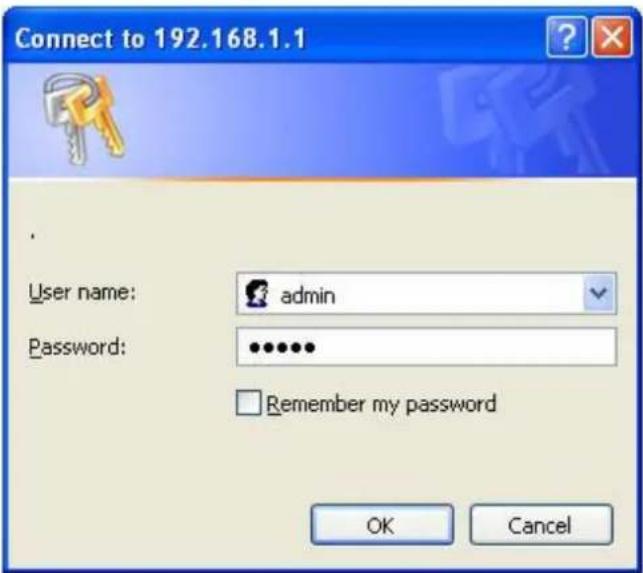
Enter admin for User Name and Password, both in lower case letters. Then click OK button or press Enter key.
Now you will get into the web interface of the device. The Main screen will appear.
Note: If the above screen does not prompt, it means that your web-browser has been set to using a proxy. Go to Tools menu>Internet Options>Connections>LAN Settings, in the screen that appears, cancel the Using Proxy checkbox, and click OK to finish it.
Now you have logged into the web interface of the router. First, you will see the System Status page.

4.2 Changing Password
Now, we recommend that you change the password to protect the security of your router. Please go to Management—Web Login Password change the password required to log in your router.
PASSWORD SETUP
This page is used to set the account to access the web server of Access Point. Empty user name and password will disable the protection.

User Name: type in the name that you use to login the web interface of the router. New Password: new password is used for administrator authentication. Confirm Password: new password should be re-entered to verify its accuracy.
Note: password length is 8 characters maximum, characters after the 8^th position will be truncated.
4.3 Setup Wizard
Setup Wizard is provided as part of the web configuration utility. Users can simply finish the settings on this page to access Internet.
| Status | - |
| Setup Wizard | + |
| • Setup Wizard | |
| Quick Setup | - |
| TCP/IP Settings | - |
| Wireless | - |
| Route Setup | - |
| Firewall | - |
| Management | - |
| Advanced | - |
- Click on the Setup Wizard on the left navigation menu, then the following screen will appear. Click Next to continue.
SETUP WIZARD
The setup wizard will guide you to configure access point for first time. Please follow the setup wizard step by step.
- Show Operation Mode
- Choose your Time Zone
- Setup LAN Interface
- Setup WAN Interface
- Wireless Basic Setting
- Wireless Security Setting
Next>>
- This router provides six operation modes: Wireless ISP Client Router, Wireless Client and Repeater (Range Extender), Router, Bridge with AP and Client. As the default mode is Router mode, you just need to click Next to continue other settings. Otherwise, click Setup Operation Mode Button to select one operation mode according to need.
1. MODE
This page shows you the selected router mode.
| Router | In this mode, the device is supposed to connect to internet via ADSL/Cable Modem. The NAT is enabled and PCs in LAN ports share the same IP to ISP through WAN port. The connection type can be setup in WAN page by using PPPOE, DHCP client, PPTP client, L2TP client or static IP. |
Cancel <
- After click Setup Operation Mode Button, the operation mode select interface will appear, please choose the proper mode refer to the introduction. Click Save Changes.
OPERATION MODE
You can setup different modes to LAN and WLAN interface for NAT and bridging function.
| ○ Wireless ISP Client Router | Wirelessly connect to WISP station/hotspot to share Internet to local wireless and wired network |
| ○ Wireless Client | In this mode, all ethernet ports are bridged together and the wireless client will connect to ISP access point. The NAT is enabled and PCs in ethernet ports share the same IP to ISP through wireless LAN. You can connect to the ISP AP in Site-Survey page. The connection type can be setup in WAN page by using PPPOE, DHCP client, PPTP client, L2TP client or static IP. |
| ○ Repeater(Range Extender) | Extend your existing wireless coverage by relaying wireless signal. |
| ○ Router | In this mode, the device is supposed to connect to internet via ADSL/Cable Modem. The NAT is enabled and PCs in LAN ports share the same IP to ISP through WAN port. The connection type can be setup in WAN page by using PPPOE, DHCP client, PPTP client, L2TP client or static IP. |
| ○ Bridge with AP | Combine two local networks via wireless connection. |
| ○ Client | Acting as a "Wireless Adapter" to connect your wired devices(e.g.Xbox/PS3) to a wireless network. |
Save Changes << Back
A: Wireless ISP Client Router
In this mode, it will wirelessly connect to WISP station/hotspot to share Internet to local wireless and wired network.
B: Wireless Client
In this mode, all Ethernet ports are bridged together and the wireless client will connect to ISP access point. The NAT is enabled and PCs in Ethernet ports share the same IP to ISP through wireless LAN. You can connect to the ISP AP in Site-Survey page. The connection type can be setup in WAN page by using PPPOE, DHCP client, PPTP client, L2TP client or static IP.
C: Repeater (Range Extender)
In this mode, the device can copy and reinforce the existing wireless signal to extend the coverage of the signal, especially for a large space to eliminate signal-blind corners. It is good for extending your existing wireless coverage by relaying wireless signal.
D: Router
In this mode, the device enables multi-users to share Internet via ADSL/Cable Modem. The Wireless port share the same IP to ISP through Ethernet WAN port .The Wireless port acts the same as a LAN port while at AP Router mode. The connection type can be setup in WAN page by using PPPOE, DHCP client, PPTP client, L2TP client or static IP.
E: Bridge with AP
In this mode, the device can be used to combine multiple local networks together to the
same one via wireless connections, especially for a home or office where separated networks can't be connected easily together with a cable.
F: Client
In this mode, the device can be connected to another device via Ethernet port and act as a "Wireless Adapter" to connect your wired device to a wireless network.
4.3.1 Router Mode
After selecting the Router mode in the last step, click next to continue the other settings.
- This page allows you to maintain the system time synchronizing with a public time server over the Internet. Here, you can specify the device's time zone according to GMT (Greenwich Mean Time). Then click Next.
2. TIME ZONE SETTING
You can maintain the system time by synchronizing with a public time server over the Internet.
□ Enable NTP client update
□ Automatically Adjust Daylight Saving
Time Zone Select:
(GMT+03:00)Moscow, St. Petersburg, Volgograd
SNTP server:
192.5.41.41 - North America
Cancel <
Enable NTP client update: NTP means Network Time Protocol which is used to make the computer's time synchronized with its server or clock source, such as Quartz and GPS. It can provide high-precision time correction and prevent harmful protocol attack by confirming encryption. You need to check this box to activate this page.
Automatically Adjust Daylight Saving: If the Time Zone you choose implements daylight saving time, please select this option.
Time Zone Select: Select the Time Zone where the router is located.
SNTP server: Please choose the corresponding SNTP server to get right time.
- This page is used to configure the parameters for local area network which connects to the LAN port of your Access Point.
3. LAN INTERFACE SETUP
This page is used to configure the parameters for local area network which connects to the LAN port of your Access Point. Here you may change the setting for IP address, subnet mask, DHCP, etc..
IP Address:
192.168.1.1
Subnet Mask:
255.255.255.0
Cancel
<<Back
Next>>
IP Address: this is the IP address to be represented by the LAN (including WLAN) interface that is connected to the internal network. This IP will be used for the routing of the internal network (it will be the Gateway IP for all the devices connected on the internal
network).
Subnet Mask: this is used to define the device IP classification for the chosen IP address range. 255.255.255.0 is a typical netmask value for Class C networks which support IP address range from 192.0.0.x to 223.255.255.x. Class C network netmask uses 24 bits to identify the network and 8 bits to identify the host.
- This interface is used to configure the parameters for Internet network which connects to the WAN port of your Access Point.
4.WAN INTERFACE SETUP
This page is used to configure the parameters for Internet network which connects to the WAN port of your Access Point. Here you may change the access method to static IP, DHCP, PPPoE, PPTP or L2TP by click the item value of WAN Access type.
WAN Access Type:
DHCP Client

Cancel
<<Back
Next>>
WAN Access Type: there are five methods provided to allow you to access Internet. Please choose the appropriate one according to the information from your ISP (Internet Service Provider).
(1). Static IP
If your ISP has provided the fixed IP that allows you to access Internet, please choose this option.
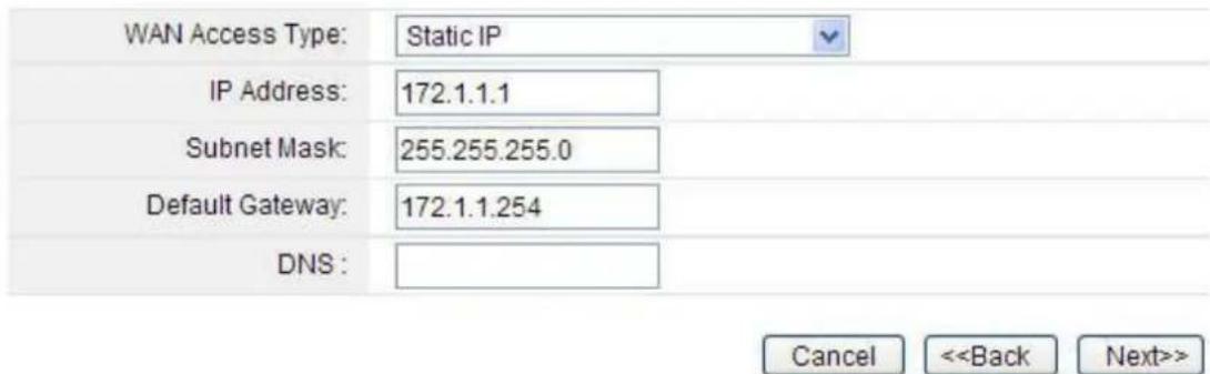
IP Address: the IP address provided by your ISP.
Subnet Mask: This is used to define the device IP classification for the chosen IP address range. 255.255.255.0 is a typical net mask value for Class C networks. Generally it is provided by your ISP.
Default Gateway: This is the IP address of the host router that resides on the external network and provides the point of connection to the next hop towards the Internet. This can be a DSL modem, Cable modem, or a WISP gateway router. The router will direct all the packets to the gateway if the destination host is not within the local network.
DNS: The Domain Name System (DNS) is an Internet “phone book”, which translates domain names to IP addresses. These fields identify the server IP addresses where the DNS requested are forwarded by this router.
(2). DHCP
Dynamic Host Configuration Protocol (DHCP) is a local area network protocol. If you choose this mode, you will get a dynamic IP address from your ISP automatically.

(3). PPPoE
Point-to-Point Protocol over Ethernet (PPPoE) is a virtual private and secure connection between two systems that enables encapsulated data transport. It replied on two widely accepted standards: PPP and Ethernet. The router supports dual access in this WAN type, you could choose the proper one according to what your ISP provides for you.
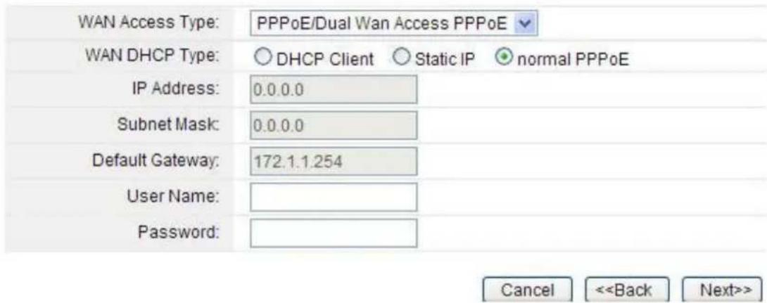
User Name: a specific valid ADSL user name provided by your ISP.
Password: the corresponding valid password provided by your ISP.
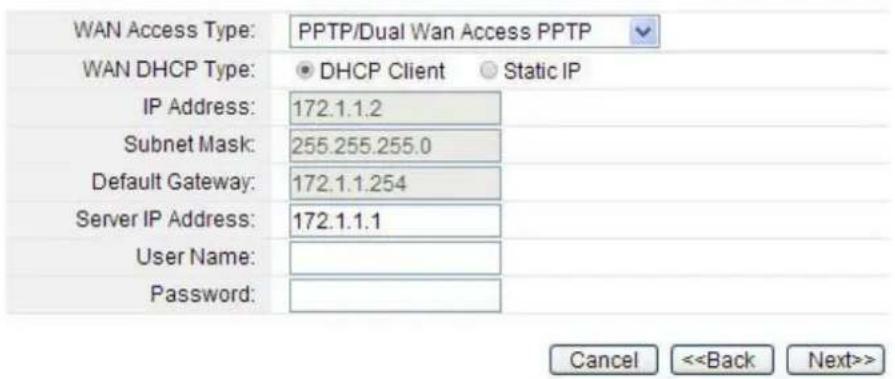
(4). PPTP
PPTP means Point to Point Tunneling Protocol is a VPN connection that only applies in Europe. If you choose one of them, please type in all the information that your ISP provided for this protocol:
(5). L2TP
L2TP means Layer 2 Tunneling Protocol is a VPN connection that only applies in Europe, Middle East and Africa (MEA) regions. If you choose one of them, please type in all the information that your ISP provided for this protocol:

- The general wireless settings, such as wireless mode, SSID and channel can be configured in this section.
5. WIRELESS BASIC SETTING
This page is used to configure the parameters for wireless LAN clients which may connect to your Access Point. Here you may change wireless encryption settings as well as wireless network parameters.

Band: In fact, this option allows you to choose the radio standard for operation of your router. 802.11b and 802.11g are old 2.4GHz mode, while 802.11n (2.4GHz and/or 5GHz, in this case, only supports 2.4GHz) is the latest standard based on faster Orthogonal Frequency Division Multiplexing (OFDM) modulation. Here, you can choose the last one 2.4GHz (B+G+N), this mode offers better compatibility.
Mode: Wireless mode specifies the operating mode of the device. The mode depends on the network topology requirements. There are 2 operating modes supported in this software.
AP: This mode allows users with laptop to surf Internet by wireless connection. It's designed to add wireless function for existed wired router which is just suitable for home and small offices.
Client: If you choose this mode, the Channel Number and Channel Width can't be edited.
Note: If you select WDS, you can't change SSID.
SSID---Service Set Identifier used to identify your 802.11 wireless LAN should be specified while operating in AP or AP+WDS mode. All the client devices within the range will receive broadcast messages from the access point advertising this SSID.
Channel Width---This is the spectral width of the radio channel. Supported wireless channel spectrum widths:
20MHz is the standard channel spectrum width.
40MHz is the channel spectrum with the width of 40MHz (selected by default).
Control Sideband---This function is to control the sideband of the radio channel.
Upper: By default, it is Upper, and the Channel Number is 11.
Lower: If you choose Lower, the Channel Number will change to Auto automatically and you can't change the Control Sideband at the same time. The selectable Channel Number now will range from 1 to 9. Only when you choose other Channel Number you will activate the Control Sideband again. If you choose Upper, the Channel Number selectable will range from 5 to 13.
Channel Number---this option provides selectable channel numbers.
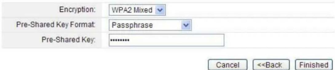
- By default, the encryption type is disabled. For a secure connection, WPA2 Mixed is recommended for you to protect your network.
6. WIRELESS SECURITY SETUP
This page allows you to setup the wireless security. Turn on WEP or WPA by using Encryption Keys could prevent any unauthorized access to your wireless network.
CHANGE SETTING SUCCESSFULLY!
Do not turn off or reboot the Device during this time. Please wait 34 seconds ...| Wi-Fi Configuration | |
| Mode | Local AP |
| Band | 2.4 GHz (B+G+N) |
| SSID | TOTOLINK N150RT |
| Channel Number | 9 |
| Encryption | Disabled(AP), Disabled(WDS) |
| BSSID | 78:44:76:b4:b7:42 |
| WISP status | |
| Mode | Wireless ISP |
| SSID | zion |
| Encryption | WPA |
| BSSID | 00:0e:e8:64:07:56 |
| Status | Connected |
| Connected Clients | 1 |
| Signal Strength | 36% |
4.3.3 Wireless Client Mode
The first three steps are the same with Router mode too. Wireless Basic Setting interface is also different with the Router mode. See below. Please5. WIRELESS BASIC SETTING
This page is used to configure the parameters for wireless LAN clients which may connect to your Access Point. Here you may change wireless encryption settings as well as wireless network parameters.  After configuration, it will also come back to the system status interface, and you can see the Wi-Fi Configuration column. The signal strength is also shown here. 4.3.4 Repeater Mode
1. In the Repeater Mode, the Time Zone Setting is the same with the Router Mode. 2. The LAN Interface Setting is the same with the Router Mode too. 3. The WAN interface setting is unvalued in Repeater Mode. See Below:4.WAN INTERFACE SETUP
This page is used to configure the parameters for Internet network which connects to the WAN port of your Access Point. Here you may change the access method to static IP, DHCP, PPPoE, PPTP or L2TP by click the item value of WAN Access type.  4. Wireless Basic Setting interface is also different with the Router mode. See below:5. WIRELESS BASIC SETTING
This page is used to configure the parameters for wireless LAN clients which may connect to your Access Point. Here you may change wireless encryption settings as well as wireless network parameters.  5. Click Find Wi-Fi networks Button, the site survey interface will appear. You should click Site Survey button to scan the wireless network, and then choose one as upper AP. After selection please click next to continue the setup wizard.WIRELESS SITE SURVEY
This page provides tool to scan the wireless network. If any Access Point or IBSS is found, you could choose to connect it manually when client mode is enabled. Site Survey| SSID | BSSID | Channel | Type | Encrypt | Signal | Select |
| TOTOLINK N302R+ | 78:44:76:00:00:00 | 11(B+G+N) | AP | no | 64 | |
| zion | 00:0e:e8:64:07:56 | 9 (B+G) | AP | WPA-PSK | 60 | |
| TOTOLINK N500RDG | 78:44:76:00:00:04 | 11(B+G+N) | AP | no | 58 | |
| TOTOLINK iPuppy | 00:0c:43:30:50:88 | 11(B+G+N) | AP | no | 50 | |
| arirang | 20:dc:e6:9d:fc:62 | 6(B+G+N) | AP | WPA-PSK/WPA2-PSK | 6 | |
| iptime | 64:e5:99:23:81:d4 | 11(B+G+N) | AP | no | 6 |
Next>>
6. When there comes to this page, you should enter the correct Pre-Shared Key to connect to the network if the network has enabled encryption. Then click Connect button.WIRELESS SITE SURVEY
This page provides tool to scan the wireless network. If any Access Point or IBSS is found, you could choose to connect it manually when client mode is enabled. 4.3.6 Client Mode
The first three steps are the same with the Repeater Mode. The Wireless Basic Setting is different from Repeater Mode. See below:5. WIRELESS BASIC SETTING
This page is used to configure the parameters for wireless LAN clients which may connect to your Access Point. Here you may change wireless encryption settings as well as wireless network parameters.  It will come back to status interface, and you can see the Wi-Fi Configuration column in the system status page. If you have setup Client mode successfully, you will see that the Mode is Infrastructure Client here, and the signal strength is also shown in this page.| Wi-Fi Configuration | |
| Mode | Infrastructure Client |
| Band | 2.4 GHz (B+G+N) |
| SSID | TOTOLINK N150RT |
| Channel Number | 9 |
| Encryption | WPA |
| BSSID | 00:00:00:00:00:00 |
| Status | Scanning |
| Signal Strength | 0% |
4.4 Quick Setup
Quick Setup is provided as part of the web configuration utility. Users can simply finish the settings all in one page to access Internet. In this section, you can setup LAN, WAN, WLAN and Time Zone Settings. Please click Save button to apply the configuration when you have completed the settings on this page.QUICK SETUP
LAN Interface Setup| IP Address:: | 192.168.1.1 |
| Subnet Mask:: | 255.255.255.0 |
| WAN Access Type: | DHCP Client |
| DNS Type | Attain DNS Automatically Set DNS Manually |
| DNS 1: | |
| DNS 2: |
| Disable Wireless LAN Interface | |
| Band: | 2.4 GHz (B+G+N) |
| Mode: | AP |
| SSID: | TOTOLINK N150RT |
| Channel Width: | 40MHz |
| Control Sideband: | Upper |
| Channel Number: | 11 |
| Data Rate: | Auto |
| Encryption: | Disable |
| Enable NTP client update | |
| Time Zone Select: | (GMT+03:00)Moscow, St. Petersburg, Volgograd |
| SNTP server: | 192.5.41.41 - North America |
Save
LAN Interface Setup
IP Address: This is the IP addresses to be represented by the LAN (including WLAN) interface that is connected to the internal network. This IP will be used for the routing of the internal network (it will be the Gateway IP for all the devices connected on the internal network). Subnet Mask: This is used to define the device IP classification for the chosen IP address range. 255.255.255.0 is a typical netmask value for Class C networks which support IP address range from 192.0.0.x to 223.255.255.x. Class C network netmask uses 24 bits to identify the network and 8 bits to identify the host.WAN Interface Setup
This part allows you to configure the WAN port parameters so that your computer can access Internet. Since we have discussed WAN Access Type on Setup Wizard, please refer to Setup Wizard to fill in the parameters.WLAN Interface Setup
Band: In fact, this option allows you to choose the radio standard for operation of your router. 802.11b and 802.11g are old 2.4GHz mode, while 802.11n (2.4GHz and/or 5GHz, in this case, only supports 2.4GHz) is the latest standard based on faster Orthogonal Frequency Division Multiplexing (OFDM) modulation. Here, you can choose the last one 2.4GHz (B+G+N), this mode offers better compatibility. Mode: Wireless mode specifies the operating mode of the device. The mode depends on the network topology requirements. There are 2 operating modes supported in this software. AP: This mode allows users with laptop to surf Internet by wireless connection. It's designed to add wireless function for existed wired router which is just suitable for home and small offices. Client: If you choose this mode, the Channel Number and Channel Width can't be edited.Time Zone Setting:
Enable NTP client update: NTP means Network Time Protocol which is used to make the computer's time synchronized with its server or clock source, such as Quartz and GPS. It can provide high-precision time correction and prevent harmful protocol attack by confirming encryption. You need to check this box to activate this page. Time Zone Select: Select the Time Zone where the router is located. SNTP server: Please choose the corresponding SNTP server to get right time.4.5 Status
4.4.1 System status
The System Status provides basic network settings of this router, including LAN, WAN and Wireless configuration. Also, you could get the current running firmware version or firmware related information from this presentation. WAN Configuration| Connect type | Getting IP from DHCP server... |
| IP Address | 0.0.0.0 / 0.0.0.0 / 0.0.0.0 |
| MAC Address | 78:44:76:b4:b7:45 |
| DNS | 0.0.0.0 |
| Mode | Local AP |
| Band | 2.4 GHz (B+G+N) |
| SSID | TOTOLINK N150RT |
| Channel Number | 11 |
| Encryption | WPA(AP), Disabled(WDS) |
| BSSID | 78:44:76:b4:b7:42 |
| Connected Clients | 1 |
| Connect type | Fixed IP |
| IP Address | 192.168.1.1 / 255.255.255.0 / 192.168.1.1 |
| DHCP Server | Enabled |
| MAC Address | 78:44:76:b4:b7:42 |
| Uptime | 0day:0h:1m:42s |
| Firmware Version | TOTOLINK-N150RT-V1.0.0-B20130917.1705 |
| Build Time | Tue Sep 17 17:06:05 CST 2013 |
| Mode | Infrastructure Client |
| Band | 2.4 GHz (B+G+N) |
| SSID | zion |
| Channel Number | 9 |
| Encryption | WPA |
| BSSID | 00:0e:e8:64:07:56 |
| Status | Connected |
| Signal Strength | 78% |
4.4.2 Statistics
This page shows the counter for sent and received packets regarding to wireless and Ethernet networks.STATISTICS
This page shows the packet counters for transmission and reception regarding to wireless and Ethernet networks.| Wireless LAN | Sent Packets | 3680 |
| Received Packets | 29836 | |
| Ethernet LAN | Sent Packets | 1679 |
| Received Packets | 3565 | |
| Ethernet WAN | Sent Packets | 0 |
| Received Packets | 0 |
4.4.3 System log
This page can be used to set remote log server and show the system log.SYSTEM LOG
This page can be used to set remote log server and show the system log.  Enable Log: this option enables the registration routine of the system log messages. By default it is disabled. Below items including system all, wireless, Dos allows you to choose the log type. Enable Remote Log: enables remote log sending function while System log messages are sent to a remote server. Log Server IP Address: this is the host IP address where system log messages should be sent. After finished, please click Save Changes.5. ADVANCED SETTINGS
This chapter allows users to configure advanced settings includes TCP/IP settings, Wireless, Route Setup, Firewall and System Management. These settings are only for more technically advanced users who have sufficient knowledge about wireless LAN. Also they should not be changed unless you know what effect the changes will have on your wireless router.5.1 TCP/IP Settings
5.1.1 LAN Interface
Local Area Network (LAN) is a group of subnets regulated and ruled by router. The design of network structure is related to what type of public IP addresses coming from your ISP. This part allows you to configure the parameters for LAN which connects to the LAN port of your Access Point.  IP Address: This is the IP addresses to be represented by the LAN (including WLAN) interface that is connected to the internal network. This IP will be used for the routing of the internal network (it will be the Gateway IP for all the devices connected on the internal network). Note: If this IP address changed, you can log into the WEB configuration interface only using the new IP address. AND if the new IP address and the original IP address are not in the same segment, the Virtual Server and DMZ Host service will not work. If you need to enable these functions, you will have to reset this IP address. Subnet Mask: This is used to define the device IP classification for the chosen IP address range. 255.255.255.0 is a typical netmask value for Class C networks which support IP address range from 192.0.0.x to 223.255.255.x. Class C network netmask uses 24 bits to identify the network and 8 bits to identify the host. DHCP: You can disable or enable this function here. DHCP Client Range: the range of IP addresses that will be assigned to each computer connected with the router. DHCP Lease Time: the IP addresses given out by the DHCP server will only be valid for the duration specified by the lease time. Increasing the time ensure client operation without interrupt, but could introduce potential conflicts. Lowering the lease time will avoid potential address conflicts, but might cause more slight interruptions to the client while it will acquire new IP addresses from the DHCP server. The time is expressed in seconds. Static DHCP: click the Set Static DHCP button to go to the Static DHCP setup interface. Domain name: this represents the name of your IP address. 802.1d Spanning Tree: Multiple interconnected bridges create larger networks using the IEEE 802.1d Spanning Tree Protocol (STP), which is used for finding the shortest path within the network and to eliminate loops from the topology. If the STP is turned on, the router will communicate with other network devices by sending and receiving Bridge Protocol Data Units (BPDU). STP should be turned off (selected by default) when this router is the only bridge on the LAN or when there are no loops in the topology as there is no sense for the bridge to participate in the Spanning Tree Protocol in this case. For IP Routing Usage: you can enable or disable this function for IP routing usage. When you enable this function, please enter the second IP address and subnet mask in the corresponding field. It will come out the Static DHCP Setup interface after you click the Set Static DHCP button. Check the box to enable static DHCP, it allows you to reserve IP addresses and assign the same IP address to the network device with the specified MAC address any time it requests an IP address.STATIC DHCP SETUP
This page allows you reserve IP addresses, and assign the same IP address to the network device with the specified MAC address any time it requests an IP address. This is almost the same as when a device has a static IP address except that the device must still request an IP address from the DHCP server. 5.1.2 WAN Interface
This part allows you to configure the WAN port parameters so that your computer can access Internet. Since we have discussed WAN Access Type on Setup Wizard, we will mainly explain PPPoE, PPTP, L2TP and the other settings here.WAN INTERFACE SETUP
This page is used to configure the parameters for Internet network which connects to the WAN port of your Access Point. Here you may change the access method to static IP, DHCP, PPPoE, PPTP or L2TP by click the item value of WAN Access type. Save Changes
MTU: it means Max Transmit Unit for packet. When using slow links, large packets can cause some delays thereby increasing lag and latency. DNS: Domain Name System. Every Internet host must have a unique IP address, also they may have a human-friendly, easy to remember name such as www.yahoo.com. The DNS server converts the user-friendly name into its equivalent IP address. Clone MAC Address: MAC address is the physical address of your computer's network card. Generally, every network card has one unique Mac address. Since many ISPs only allow one computer in LAN to access Internet, users can enable this function to make more computers surf Internet. Enable UPnP: the UPnP (Universal Plug and play) protocol is supported to bring to network connected devices the ease of installation and configuration which is already available for directly connected PC peripherals with the existing Windows "Plug and Play" system. You can enable this function so that the router doesn't need to work out which port need to be opened. Enable IGMP Proxy: IGMP is the abbreviation of Internet Group Management Protocol. It is a communication protocol which is mainly used for managing the membership of Internet Protocol multicast groups. If you select this checkbox, the application of multicast will be executed through WAN port. In addition, such function is available in NAT mode. Enable Ping Access on WAN: enable users use Ping command to access WAN.5.1.2.1 PPPoE
Select PPPoE option if ISP provides a PPPoE connection. You should enter the following parameters.  User Name/Password: enter the User Name and Password provided by your ISP. WAN DHCP type: it's available only for PPPoE connection. If your ISP provides an extra type to connect to a local area network such as DHCP Client/Static IP/normal PPPoE, you should select the type and enter the right parameters provided by ISP to enable the secondary connection. DNS: Domain Name System. If you select Set DNS Manually, you will have to type in the DNS address by yourself. It is chosen to Attain DNS by default. Connection Type: provides three modes to connect to the Internet. - Constant: the connection can be re-established automatically. - Connection on demand: the Internet connection can be terminated automatically after a specified inactivity period (idle time) and be re-established when you want to access the Internet again. - Connection manually: you can click Connect or Disconnect button to connect/disconnect immediately. Service Name (AC): this is optional. It describes the service name your ISP provided to you. Generally, leaving these fields blank will work. MTU: it means Max Transmit Unit for packet. When using slow links, large packets can cause some delays thereby increasing lag and latency. Clone MAC Address: MAC address is the physical address of your computer's network card. Generally, every network card has one unique Mac address. Since many ISPs only allow one computer in LAN to access Internet, users can enable this function to make more computers surf Internet.5.1.2.2 PPTP
You should select PPTP option if ISP provides a PPTP connection and enter the following parameters. Please refer to PPPoE configuration if there are the same parameters.   WAN DHCP type: it's available only for PPTP connection. If your ISP provides an extra type to connect to a local area network such as DHCP Client/Static IP, you should select the type and enter the right parameters provided by ISP to enable the secondary connection. MPPE: You can enable MPPE Encryption or MPPC compression here. MPPE provides link encryption. Link encryption encrypts data as it passes between the calling and answering routers. MPPC provides a method to negotiate and utilize compression protocols over PPP encapsulated links. DNS Type: If you select Set DNS Manually, you will have to type in the DNS address by yourself. It is chosen to Attain DNS by default while you select the DHCP client mode. Besides, it is Set DNS type while you select the Static IP.5.1.2.3 L2TP
You should select L2TP option if ISP provides a L2TP connection and enter the following parameters. Please refer to PPPoE configuration if there are the same parameters.  5.1.3 Alias IP
Alias IP means virtual IP. You can choose to enable this function according to your requirement.ALIAS IP SETUP
From this page you can register aliases to IP ports Access Point. 5.1.4 VLAN Settings
VLAN means Virtual Local Area Network, this function provides you a very convenient way to manage hosts by grouping them based on the physical port. You can also manage the in/out rate of each port. VLANs are created to provide the segmentation services traditionally provided by routers. VLANs address issues such as scalability, security, and network management. It can effectively satisfy user's individual requirement that if one of your family members want to watch IPTV but others want to surf Internet. You can enjoy more amazing interactive entertainment experience by IPTV. Enable VLAN
| Enable | Ethernet/Wireless | WAN/LAN | Forwarding Rule | Tag | VID(1~4090) | Priority | CFI |
| Ethernet Port1 | LAN | NAT | 3022 | 0 | |||
| Ethernet Port2 | LAN | NAT | 3030 | 7 | |||
| Ethernet Port3 | LAN | NAT | 500 | 0 | |||
| Ethernet Port4 | LAN | NAT | 1 | 3 | |||
| Wireless 1 Primary AP | LAN | NAT | 1 | 0 | |||
| Wireless 1 Virtual AP1 | LAN | NAT | 1 | 0 | |||
| Wireless 1 Virtual AP2 | LAN | NAT | 1 | 0 | |||
| Wireless 1 Virtual AP3 | LAN | NAT | 1 | 0 | |||
| Wireless 1 Virtual AP4 | LAN | NAT | 1 | 0 | |||
| Ethernet Port5 | WAN | NAT | 1 | 0 |
Apply Changes
Enable VLAN: this option enables VLAN function. Ethernet/Wireless: specifies the WAN port and wireless AP. WAN/LAN: defines the WAN port or LAN port. Forwarding Rule: VLAN feature also support forwarding rule as bridge and NAT between LAN port and WAN port. Tag: enable the function of VLAN with tag. The router will add specific VLAN number to all packets on the LAN while sending them out. Please type the tag value and specify the priority for the packets sending by LAN. VID: type the value as the VLAN ID number. The range is from 1 to 4090. Priority: Type the packet priority number for such VLAN. The range is from 0 to 7. CFI: enable the CFI function which indicates whether MAC is encapsulated by standard format. After the VLAN settings, please click Apply Changes to finish TCP/IP Settings.5.2 Wireless
5.2.1 Basic Settings
On this page, you could configure the parameters for Wireless LAN client that may connect to your Access Point. Since we have discussed wireless settings on Setup Wizard, here we will focus on the encryption, WMM function and Data Rate.  Click Multiple APs button, the multiple APs setup interface will appear. You can add other SSID for different needs. What's more, you can setup different encryption for different SSIDs in Security Settings section. We will introduce in 5.2.2 Security SettingsMULTIPLE APS
This page shows and updates the wireless setting for multiple APs.| No. | Enable | Band | SSID | Data Rate | Broadcast SSID | WMM | Access | Active Client List |
| AP1 | 2.4 GHz (B+G+N) | TOTOLINK N1 | Auto | Enabled | Enabled | LAN+WAN | Show | |
| AP2 | 2.4 GHz (B+G+N) | TOTOLINK N1 | Auto | Enabled | Enabled | LAN+WAN | Show | |
| AP3 | 2.4 GHz (B+G+N) | TOTOLINK N1 | Auto | Enabled | Enabled | LAN+WAN | Show | |
| AP4 | 2.4 GHz (B+G+N) | TOTOLINK N1 | Auto | Enabled | Enabled | LAN+WAN | Show |
Data Rate
This defines the data rate (in Mbps) at which the device should transmit wireless packets. You can fix a specific data rate between MCS 0 and MCS 7 also. It is recommended to use Auto option, especially if you are having trouble getting connected or losing data at a higher rate. MCS means Modulation Coding Scheme. Before 802.11n standard emerges, most Access Points complies with 802.11a/b/g standards and the data rate ranges from 1Mbps to 54Mbps, including only 12 possible physical speed. But when it comes to 802.11n technology, the physical speed can be affected by many factors, such as modulation type, coding rate, space flow quantity, whether 40MHz banding and so on. Combining these factors together will create a lot of selectable physical speed. Thus, 802.11n proposes the term MCS. You can consider this term to be a whole combination of these factors and every digit represents a combination. Note: If you select 20MHz Channel Spectrum width the maximum data rate is MCS7 (65Mbps). If you select 40MHz Channel Spectrum width the maximum data rate is MCS7(150Mbps). Associate Clients: Click Show Active Clients Button it will come to WiFi Station interface.ACTIVE WIRELESS CLIENT TABLE
This table shows the MAC address, transmission, reception packet counters and encrypted status for each associated wireless client.| MAC Address | Mode | Tx Packet | Rx Packe | Tx Rate (Mbps) | Power Saving | Expired Time (s) |
| None | --- | --- | --- | --- | --- | --- |
| Encryption: | WEP |
| 802.1x Authentication: | Disabled |
| Authentication: | WEP |
| Key Length: | WPA |
| WPA2 | |
| WPA-Mixed |
1) WEP
WEP (Wired Equivalent Privacy) is based on the IEEE 802.11 standard and uses the RC4 encryption algorithm. Enabling WEP allows you to increase security by encryption data being transferred over your wireless network. WEP is the oldest security algorithm, and there are few applications that can decrypt the WEP key in less than 10 minutes.  Key Length: 64-bit/128-bit, by default it is 64-bit. 64-bit—For 64 bits WEP key, either 5 ASCII characters, such as 12345 (or 10 hexadecimal digitals leading by 0x, such as 0x414234445.) 128-bit—For 128 bits WEP key, either 13 ASCII characters, such as ABCDEFGHIJKLM (or 26 hexadecimal digits leading by 0x, such as 0x4142434445464748494A4B4C4D). Key Format: If you choose 64 bit, there will be two Key Formats selectable: ASCII (5 characters) and Hex (10 characters). If 128-bit, the Key Formats should comply with ASCII (13 characters) or Hex (26 characters) Encryption Key: Please refer to Key Length to set this parameter.2) 802.1x Authentication
WPA (Wi-Fi Protected Access) is separated into two categories: WPA/PSK and WPA/802.1x. If you choose 802.1x Authentication, you will have to provide the RADIUS Server IP Address, Port and Password so that the encryption key will be obtained dynamically from RADIUS server.  RADIUS Server IP Address: Enter the IP address of RADIUS server. RADIUS Server Port: the UDP port number that the RADIUS server that is used to authenticate the messages sent between them. RADIUS Server Password: enter the password. RADIUS: Remote Authentication Dial-In User Service (RADIUS) is a security authentication client/server protocol that supports authentication, authorization and accounting, which is widely used by Internet Service Provider. It is the most common method of authenticating and authorizing dial-up and tunneled network users.3) WPA/WPA2
Wi-Fi Protected Access (WPA) is the most dominating security mechanism in industry. It is separated into two categories: WPA-personal or called WPA Pre-Share Key (WPA/PSK), and WPA-Enterprise or called WPA/802.1x. WPA2 means Wi-Fi Protected Access 2, it is the current most secure method of wireless security and required for 802.11n performance. TKIP--Temporal Key Integrity Protocol is one cipher for data encryption supported by WPA. AES--Advanced Encryption Standard is another cipher for data encryption supported by WPA.  Pre-Shared Key Format/Pre-Shared Key: This is a pre-defined key used for encryption during data transmission. It has two formats: Passphrase and Hex (64 characters). Then you need to enter the Pre-Shared Key, either 8\~63 ASCII characters, such as 012345678 (or 64 Hexadecimal digits leading by 0x, such as "0x321253abcde...").4) WPA Mixed
This option mixes WPA/WPA2 together. It will provide the best security for your router.  Note: Since WEP has been proved vulnerable, you may consider using WPA2 for the most secure connection. You should select the appropriate security mechanism according to your needs. No matter which security suite you select, they all will enhance the over-the-air data protection and/or privacy on your wireless network. Enable Universal Repeater Mode: enable the repeater mode and search for wireless networks in range on all the supported channels while device is operating in Access Point. 5.2.2 Security Settings
You can setup wireless security in this page. Setup different encryptions for different SSIDs so that makes your wireless network more secure. It is very practical for protecting your private information.WIRELESS SECURITY SETUP
This page allows you to setup the wireless security. Turn on WEP or WPA by using Encryption Keys could prevent any unauthorized access to your wireless network.  Encryption: Disabled 5.2.3 Site Survey
Utility will search for wireless networks in range on all the supported channels while device is operating in Access Point mode. This page provides a tool to scan the wireless network. If any Access Point or IBSS is found, you could choose to connect it manually when client mode is enabled.WIRELESS SITE SURVEY
This page provides tool to scan the wireless network. If any Access Point or IBSS is found, you could choose to connect it manually when client mode is enabled. Site Survey| SSID | BSSID | Channel | Type | Encrypt | Signal | Select |
| zion | 00:0e:e8:64:07:56 | 9 (B+G) | AP | WPA-PSK | 52 | ○ |
| iptime-n7004ns | 00:08:9f:00:00:20 | 9 (B+G) | AP | WPA-PSK | 32 | ○ |
| ChinaNet-qNFG | 0c:96:bf:7e:d8:08 | 1(B+G+N) | AP | WPA-PSK/WPA2-PSK | 28 | ○ |
| TOTOLINK iPuppy | 00:0c:43:30:50:88 | 6(B+G+N) | AP | WPA2-PSK | 20 | ○ |
5.2.4 WDS
WDS means Wireless Distribution System. It is a protocol for connecting two access points wirelessly. Usually, it can be used for the following application: 1. Provide bridge traffic between two LANs though the air. 2. Extend the coverage range of a WLAN. To meet the above requirement, you must set these APs in the same channel and set MAC address of other APs which you want to communicate with in the table and then enable the WDS.  Enable WDS: by default, you can't select the checkbox to enable WDS. MAC Address: the other AP's MAC Address that you want to communicate with. Data Rate: please choose the transmission data rate. Comment: describes the reason why you want to communicate with others. The WDS Security Setup allows you to set encryption for your WDS connection. You can refer to the Wireless Security Setup.5.2.5 Advanced Settings
This page handles advanced wireless settings that are only for more technically advanced users who have a sufficient knowledge about wireless LAN technology. These settings should not be changed unless you know what effect the changes will have on your Access Point. Apply Changes
Fragment Threshold: specifies the maximum size for a packet before data is fragmented into multiple packets. The range is 256-2346 bytes. Setting the Fragment Threshold too low may result in poor network performance. The use of fragment can increase the reliability of frame transmissions. Because of sending smaller frames, collisions are much less likely to occur. However, lower values of the Fragment Threshold will result in lower throughput as well. Minor or no modifications of the Fragmentation Threshold value is recommended while default setting of 2346 is optimum in most of the wireless network use cases. RTS Threshold: determines the packet size of a transmission and, through the use of an access point, helps control traffic flow. The range is 0-2347bytes. The default value is 2347, which means that RTS is disabled. RTS/CTS (Request to Send/Clear to Send) are the mechanism used by the 802.11 wireless networking protocol to reduce frame collisions introduced by the hidden terminal problem. RTS/CTS packet size threshold is 0-2347 bytes. If the packet size the node wants to transmit is larger than the threshold, the RTS/CTS handshake gets triggered. If the packet size is equal to or less than threshold the data frame gets sent immediately. System uses Request to Send/Clear to Send frames for the handshake that provide collision reduction for an access point with hidden stations. The stations are sending a RTS frame first while data is sent only after a handshake with an AP is completed. Stations respond with the CTS frame to the RTS, which provide clear media for the requesting station to send the data. CTS collision control management has a time interval defined during which all the other stations hold off the transmission and wait until the requesting station will finish transmission. Beacon Interval: By default, it is set to 100ms. Higher Beacon interval will improve the device's wireless performance and is also power-saving for client side. If this value set lower than 100ms, it will speed up the wireless client connection. Preamble Type: this option is to define the length of the sync field in an 802.11 packet. Most modern wireless network uses shot preamble with 56 bit sync filed instead of long preamble with 128 bit sync filed. However, some original 11b wireless network devices only support long preamble. By default, Long Preamble is selected. IAPP: Inter-Access Point Protocol is designed for the enforcement of unique association throughout an ESS (Extended Service Set) and for secure exchange of station's security context between current access point (AP) and new AP during handoff period. It is enabled by default. Protection: it is disabled by default. Aggregation: A part of the 802.11n standard. It allows sending multiple frames per single access to the medium by combining frames together into one larger frame. It creates the larger frame by combining smaller frames with the same physical source and destination end points and traffic class (i.e. QoS) into one large frame with a common MAC header. It is enabled by default. Frames- determine the number of frames combined on the new larger frame. Bytes- determine the size (in Bytes) of the larger frame. Short GI: short Guide Interval. It is to assure the safety of propagation delays and reflections for the sensitive digital data. WLAN Partition: divides the WLAN to several parts. 20/40MHz Coexist: enable this function will make the device select the channel with better performance automatically. It is disabled by default. RF Output Power: you can select the output power of the wireless device. The default value is 100%. It will deliver the best performance of the device.5.2.6 Access Control
 By default, Wireless Access Control Mode is disabled. There are two ways to set the Access Control List: 1. If you select Allow List and enter the MAC Address of wireless client, the listed address will have granted access to the Access Point while the other access will be denied. 2. If you select Deny List and enter the MAC Address of wireless client, the listed address will have denied access to the Access Point while the other access will be granted. MAC Address: the wireless MAC address that you allow to access or not. Comment: describe the reason why you allow or deny the access of the MAC Address. You need to click Apply Changes to make your setting work. Current Access Control List: this list will show all the current access control that you have set. And you're able to delete some or all of them using the Delete Selected or Delete All button.5.2.7 WPS Settings
WPS (Wi-Fi Protected Setup) provides easy procedure to make network connection between wireless station and wireless access point with the encryption of WPA and WPA2.  Self-PIN Number: it will show the PIN Number of your device. Push Button Configuration: click Start PBC button to invoke Push-Button style WPS setup procedure. The router will wait for WPS requests from wireless clients about two minutes. The WPS LED on the router will blink fast when WPS is in progress. It will return to normal condition after two minutes. (You need to setup WPS within two minutes.) STOP WSC: Click the button to stop WSC function. Client PIN Number: please input the PIN code specified in wireless client you wish to connect, and click Start PIN button. The WPS LED on the router will blink fast when WPS is in progress. It will return to normal condition after two minutes. (You need to setup WPS within two minutes) Current Key Info: If the wireless security (encryption) function of the router is properly configured, you can see the encryption information on the list.5.2.8 Schedule
This router has a built-in real time clock which can update itself manually or automatically by means of Network Time Protocol (NTP). As a result, you can not only schedule the router to dialup to the Internet at a specified time, but also restrict Internet access to certain hours so that users can connect to the Internet only during certain hours, say, business hours. The schedule is also applicable to other functions. You have to set your time before setting schedule.WIRELESS SCHEDULE
This page allows you setup the wireless schedule rule. Please do not forget to configure system time before enable this feature. 5.3 Route Setup
5.3.1 Static Route
This page is used to setup dynamic or static routing protocol. Enable Dynamic Route
You may want to set up your router to route computers or devices on your network to other local networks through other routers. If other routers support dynamic routing such as RIP (Routing Information Protocol), you can enable this feature on your router to automatically learn the required routes to reach those networks. It is required that the same dynamic routing protocol and version is also enabled on the other routers in order your router and the other users to exchange information about the network. Select the checkbox to enable Dynamic Route function. Note: Configuring this feature assumes that you have some general networking knowledge. NAT: by default, this option is selected. Detailed information about this parameter refers to the discussion before. Transmit: allows your router to send out network information to other routers so other routers can dynamically build routes to your network. Disabled— disable sending routing information from your router to other routers. RIP1— sends out routing information to other routers using the RIP version 1 protocol. RIP2— sends out routing information to other routers using the RIP version 2 protocol. Receive: allows your router to receive network information from other routers so your router can build routes to other networks. Disabled— disable receiving routing information from other router to your router. RIP1— receive routing information from other routers using the RIP version 1 protocol. RIP2— receive routing information from other routers using the RIP version 2 protocol. Enable Static Route: this part allows you to specify that a specific target IP addresses passes through a determined gateway manually. IP Address: type in the target network IP. Subnet Mask: type in the Netmask. Gateway: type in the Gateway IP. Metric: enter the metric or priority of the route. The metric range is 1 to 15, the lowest number 1 being the highest priority. Interface: click the drop-down list and select the interface on your router where the route is active. Static Route Table: this table will list the detailed information about the target network IP.5.3.2 Routing Table
This table shows detail information of all the routing entry.ROUTING TABLE
This table shows the all routing entry.| Destination | Gateway | Genmask | Metric | Interface | Type |
| 239.255.255.250 | 0.0.0.0 | 255.255.255.255 | 0 | LAN | Dynamic |
| 192.168.1.0 | 0.0.0.0 | 255.255.255.0 | 0 | LAN | Dynamic |
| 224.0.0.0 | 0.0.0.0 | 240.0.0.0 | 0 | LAN | Dynamic |
5.4 Firewall
While the broadband users demand more bandwidth for multimedia, interactive applications, or distance learning, security has been always the most concerned. The firewall of this router helps to protect you local network against attack from unauthorized outsiders. It also restricts users in the local network from accessing the Internet. Furthermore, it can filter out specific packets that trigger the router to build an unwanted outgoing connection. 5.4.1 IP Filtering
 Enable IP filtering: you can select this checkbox to enable IP Filtering function. Local IP Address: the IP address that you want to filter. Protocol: choose which particular protocol type should be filtered. Here you can choose UDP/TCP. Comment: describe the reason why you want to filter the IP address. Just few words are saved there usually. IP Filter Table: this table will list the detailed information about the IP addresses that will be filtered.5.4.2 Port Filtering
 Enable Port Filtering: you can select this checkbox to enable Port Filtering function. Port Range: the port range that you want to filter. Protocol: choose which particular protocol type should be filtered. Here you can choose UDP/TCP. Comment: describe the reason why you want to filter these ports. Just few words are saved there usually. PORT Filter Table: this table will list the detailed information about the ports that will be filtered.5.4.3 MAC Filtering
 Enable MAC Filtering: you can check the box to enable MAC Filtering function. MAC Address: the MAC address that you want to filter. Comment: describe the reason why you want to filter the MAC address. Just few words are saved there usually. MAC Filter Table: this table will list the detailed information about the MAC addresses that will be filtered.5.4.4 URL Filtering
URL FILTERING
URL filter is used to deny LAN users from accessing the internet. Block those URLs which contain keywords listed below.  Enable URL Filtering: you can select this checkbox to enable URL filtering function. URL Addresses: type in the keywords contained in URLs that you don't allow LAN users to access. URL Filter Table: this table will list the detailed information about the keywords contained in URLs that you don't allow LAN users to access.5.4.5 Port Forwarding
 Port Forwarding creates a transparent tunnel through a firewall/NAT, granting an access from the WAN side to the particular network service running on the LAN side. These settings are only necessary if you wish to host some sort of server like a web server or mail server on the private local network behind your Gateway's NAT firewall. Enable Port Forwarding: you can select this checkbox to enable Port Forwarding function. IP Address: enter the Port's IP address. Protocol: choose which particular protocol type should be forwarding. Here you can choose Both/UDP/TCP. Port Range: set the range that the port forward to. Comment: describe the reason why you want to use port forward function. Just few words are saved there usually. Port Forwarding Table: this table will list the detailed information about the ports that will be forwarded.5.4.6 DMZ
DMZ
A Demilitarized Zone is used to provide Internet services without sacrificing unauthorized access to its local private network. Typically, the DMZ host contains devices accessible to Internet traffic, such as Web (HTTP) servers, FTP servers, SMTP (e-mail) servers and DNS servers. Enable DMZ DMZ Host IP Address: Apply Changes DMZ means Demilitarized Zone. It can be enabled and used as a place where services can be placed such as Web Servers, Proxy Servers and E-mail Servers such that these services can still serve the local network and are at the same time isolated from it for additional security. DMZ is commonly used with the NAT functionality as an alternative for the Port Forwarding while makes all the ports of the host network device be visible from the external network side. Enable DMZ: you can select this checkbox to Enable DMZ function. DMZ Host IP Address: type in the IP address of the DMZ host.5.4.7 Denial-of-Service
The DoS Prevention functionality helps you to detect and mitigate the DoS attack. The attacks are usually categorized into two types, the flooding-type attacks and the vulnerability attacks. The flooding-type attacks will attempt to exhaust all your system's resource while the vulnerability attacks will try to paralyze the system by offending the vulnerabilities of the protocol or operation system. The DoS Prevention function enables the router to inspect every incoming packet based on the attack signature database. Any malicious packet that might duplicate itself to paralyze the host in the secure LAN will be strictly blocked and a Syslog message will be sent as warning, if you set up Syslog server. Also this router monitors the traffic. Any abnormal traffic flow violating the pre-defined parameter, such as the number of thresholds, is identified as an attack and the CPE will activate its defence mechanism to mitigate in a real-time manner.  Enable DoS Prevention: check this box to enable DoS prevention function. This page shows the attack types that DoS prevention function can detect: Whole System Flood: SYN Whole System Flood: FIN Whole System Flood: UDP ICMP Smurf IP Land IP Spoof| Whole System Flood: ICMP | IP TearDrop |
| Per-Source IP Flood: SYN | PingofDeath |
| Per-Source IP Flood: FIN | TCP Scan |
| Per-Source IP Flood: UDP | TCP SynWithData |
| Per-Source IP Flood: ICMP | UDP Bomb |
| TCP/UDP PortScan | UDP EchoChargen |
5.4.8 NAT Mapping
NAT Mapping function is very useful for a domestic network with one wireless router and a few devices with private IP addresses.NAT MAPPING
 Public IP Address: enter the public IP address provided by corresponding service provider. Private IP Address: enter the private IP address of your PC.5.5 Management
5.5.1 Upgrade Firmware
New version of firmware will be released to improve the various efficiency or to fix some bugs. Following the steps show below so as to realize upgrading. This page allows you to upgrade the Access Point firmware to new version. Please note: DO NOT power off the device during the upload because it may crash the system.UPGRADE FIRMWARE
This page allows you upgrade the Access Point firmware to new version. Please note, do not power off the device during the upload because it may crash the system.  Firmware version: shows the current firmware version. Choose File: select the firmware version you want to upgrade on your computer. Click Upload to upgrade the firmware version.5.5.2 Save/Reload Setting
This page allows you to save current settings to a file or reload the settings from the file which was saved previously. Besides, you can reset the current configuration to factory default.SAVE/RELOAD SETTINGS
This page allows you save current settings to a file or reload the settings from the file which was saved previously. Besides, you could reset the current configuration to factory default.  Save Settings to File: click Save... button to download the current settings of the Access Point to your computer. Load Settings from File: if you want to reload the settings from the file saved before, you could click Choose File button to choose the right file then click Upload button. Reset Settings to Default: this Reset button is provided to allow you to restore the router settings to the default factory settings.5.5.3 Web Login Password
In this section you can modify the administrator password to protect your device from unauthorized configuration. The default administrator's password should be changed on the very first system setup.PASSWORD SETUP
This page is used to set the account to access the web server of Access Point. Empty user name and password will disable the protection.| User Name: | admin | |
| New Password: | ...... | |
| Confirmed Password: | ||
| Apply Changes | ||
5.5.4 TR-069 Config
TR-069 stands for CPE WAN Management Protocol. It is a protocol for communication between Customer Premise Equipment (CPE) and Auto-Configuration Server (ACS) that encompasses secure auto-configuration as well as other CPE management functions within a common framework. On this page you can configure the TR-069 CPE and change the setting of ACS.TR-069 CONFIG
On this page you can configure the TR-069 CPE. Here you can change the setting of ACS. ACS:
URL: enter the URL of ACS which is provided by your ISP User Name & Password: provided by your ISP. Enable periodic information: choose On to enable the periodic information. Interval periodic updates: the interval of periodic inform (only if you enable the periodic information does it take effect)Connection Request
User Name: enter the CPE Connection Request User Name. Password: enter CPE Connection Request Password. Port: enter the CPE connection port number for connecting to ACS.5.5.5 Date and Time
 You can specify the device's time zone according to GMT (Greenwich Mean Time) or copy computer time as the current time only by clicking the Copy Computer Time button. Enable NTP client update: NTP means Network Time Protocol which is used to make the computer's time synchronized with its server or clock source, such as Quartz and GPS. It can provide high-precision time correction and prevent harmful protocol attack by confirming encryption. You need to check this box to activate this page. Time Zone Select: Select the Time Zone where the router is located. SNTP server: Please choose the corresponding SNTP server to get right time.5.5.6 Reboot Router
You can just click Reboot to restore the router to default factory setting.REBOOT ROUTER
Reboot Router Reboot Router5.5.7 Reboot Schedule
After enabled the Reboot schedule, the router will automatically reboot at the time that you set here. You have to set your time before setting schedule.REBOOT SCHEDULE
The schedule function allows you to setup the time that the router will reboot automatically.  Save Changes5.6 Advanced
The Advanced Setup includes DDNS, QoS, Operation Mode and SSH Server. You can configure these function refer to the introduction below. 5.6.1 DDNS
DDNS means Dynamic Domain Name System. The ISP often provides you with a dynamic IP address when you connect to the Internet via your ISP. It means that the public IP address assigned to your router changes each time you access the Internet. The Dynamic DNS feature lets you assign a domain name to a dynamic WAN IP address. It allows the router to update its online WAN IP address mappings on the specified Dynamic DNS server. Once the router is online, you will be able to use the registered domain name to access the router or internal virtual servers from the Internet. It is particularly helpful if you host a web server, FTP server, or other server behind the router. Before you user the Dynamic DNS feature, you have to apply for free DDNS service to the DDNS service providers. The router provides up to three accounts from three different DDNS service providers. This router supports three service providers: DynDNS, TZO and NOIP.DYNAMIC DNS
Dynamic DNS is a service, that provides you with a valid, unchanging, internet domain name (an URL) to go with that (possibly everchanging) IP-address  Enable DDNS: please select this checkbox to enable DDNS function. Service Provider: choose one service provider where you have applied for free DDNS service. Domain Name: type in the domain name you registered from the DDNS provider. User Name/Email: enter the User Name or Email you registered from the DDNS provider. Password/Key: enter the Password or Key you set for the User Name. Click Save Changes to finish the setting.5.6.2 QoS
QoS means Quality of Service. Deploying QoS management to guarantee that all applications receive the service levels required and sufficient bandwidth to meet performance expectations is indeed one important aspect of modern enterprise network. Since numerous TCP-based applications tend to continually increase their transmission rate and consume all available bandwidth, we need QoS to control the bandwidth use. On this page, you could set the QoS rules.  Automatic Uplink Speed: this option allows you to set the total uplink speed automatically. Manual Uplink Speed (Kbps): set the uplink speed by entering a number in the blank. Automatic Downlink Speed: this allows you to set the total downlink. By default, it is 4096Kbps as well. Manual Downlink Speed (Kbps): set the uplink speed by entering a number in the blank. QoS Rule Setting Address type: it allows users control the bandwidth by IP or MAC. Local IP Address: enter the IP address range if address type is IP. MAC address: enter the MAC address if address type is MAC. Mode: Guaranteed minimum bandwidth and restricted maximum bandwidth are selectable. Uplink Bandwidth: please set the max uplink bandwidth. Downlink Bandwidth: please set the max downlink bandwidth. Current QoS Rules Table: this table will list the detailed parameter about QoS. Click Apply Changes to finish the setting.5.6.3 Operation mode
This parameter specifies the operating network modes for the router. Since we have introduced on the Setup Wizard section, just refer to Setup WizardOPERATION MODE
You can setup different modes to LAN and WLAN interface for NAT and bridging function.| ○ Wireless ISP Client Router | Wirelessly connect to WISP station/hotspot to share Internet to local wireless and wired network |
| ○ Wireless Client | In this mode, all ethernet ports are bridged together and the wireless client will connect to ISP access point. The NAT is enabled and PCs in ethernet ports share the same IP to ISP through wireless LAN. You can connect to the ISP AP in Site-Survey page. The connection type can be setup in WAN page by using PPPOE, DHCP client, PPTP client, L2TP client or static IP. |
| ○ Repeater(Range Extender) | Extend your existing wireless coverage by relaying wireless signal. |
| ○ Router | In this mode, the device is supposed to connect to internet via ADSL/Cable Modem. The NAT is enabled and PCs in LAN ports share the same IP to ISP through WAN port. The connection type can be setup in WAN page by using PPPOE, DHCP client, PPTP client, L2TP client or static IP. |
| ○ Bridge with AP | Combine two local networks via wireless connection. |
| ○ Client | Acting as a "Wireless Adapter" to connect your wired devices(e.g.Xbox/PS3) to a wireless network. |
OPERATION MODE HELP
Client Router: In this mode, the device enables multiusers to Internet from WISP. The LAN port devices share the same IP from WISP through Wireless port. While connecting to WISP, the Wireless port works as a WAN port at AP client Router mode. The ethernet port acts as a LAN port Repeater(Range Extender): In this mode, the device can copy and reinforce the existing wireless signal to extend the coverage of the signal, especially for a large space to eliminate signal-blind corners Router: In this mode, the device enables multiusers to share Internet via ADSL/Cable Modem. The Wireless port share the same IP to ISP through ethernet WAN port. The Wireless port acts the same as a LAN port while at AP Router mode Bridge with AP: In this mode, the device can be used to combine multiple local networks together to the same one via wireless connections, especially for a home or office where separated networks can not be connected easily together with a cable Client: In this mode, the device can be connected to another device via Ethernet port and act as an adaptor to grant your wired devices access to a wireless network, especially for a Smart TU.Mdia Player or game console only with an Ethernet port Be sure to click the Save button to save your settings on this page << Back5.6.4 SSH Server
SSH SERVER
SSH Server, allow you login router by command GUI.  Enable SSH Server: SSH means Secure Share. It is the most secure protocol specially used for remote login and other web service. Server User: type in a name for the SSH server. SSH Password: type in the password for security.
- ABOUT THIS GUIDE......3
- PRODUCT OVERVIEW....3
- HARDWARE INSTALLATION....6
- CONNECTING TO INTERNET 8
- ADVANCED SETTINGS....27
- TCP/IP Settings....27
- Wireless....34
- Route Setup 43
- Firewall 45
- Management....50
- ABOUT THIS GUIDE
- Navigation of the User's Guide
- PRODUCT OVERVIEW
- Introduction
- Features
- Panel Layout
- Front Panel
- Rear Panel
- HARDWARE INSTALLATION
- Hardware Installation
- Check the Installation
- Set up the Computer
- ◆ Configure the IP address manually
- ♦ Obtain an IP address automatically
- Is the connection between your PC and the router correct?
- Is the TCP/IP configuration for your PC correct?
- CONNECTING TO INTERNET
- Accessing Web page
- Changing Password
- PASSWORD SETUP
- Setup Wizard
- SETUP WIZARD
- MODE
- OPERATION MODE
- A: Wireless ISP Client Router
- B: Wireless Client
- C: Repeater (Range Extender)
- D: Router
- E: Bridge with AP
- F: Client
- Router Mode
- TIME ZONE SETTING
- LAN INTERFACE SETUP
- 4.WAN INTERFACE SETUP
- (3). PPPoE
- (4). PPTP
- (5). L2TP
- WIRELESS BASIC SETTING
- WIRELESS SECURITY SETUP
- CHANGE SETTING SUCCESSFULLY!
- Wireless ISP Client Mode
- Wireless Client Mode
- Repeater Mode
- WIRELESS SITE SURVEY
- Next>>
- Bridge with AP
- Client Mode
- Quick Setup
- QUICK SETUP
- Save
- LAN Interface Setup
- WAN Interface Setup
- WLAN Interface Setup
- Time Zone Setting:
- Status
- System status
- Statistics
- STATISTICS
- System log
- SYSTEM LOG
- ADVANCED SETTINGS
- TCP/IP Settings
- LAN Interface
- STATIC DHCP SETUP
- WAN Interface
- Save Changes
- PPPoE
- PPTP
- L2TP
- Alias IP
- ALIAS IP SETUP
- VLAN Settings
- Enable VLAN
- Apply Changes
- Wireless
- Basic Settings
- MULTIPLE APS
- Data Rate
- ACTIVE WIRELESS CLIENT TABLE
- 1) WEP
- 2) 802.1x Authentication
- 3) WPA/WPA2
- 4) WPA Mixed
- Security Settings
- WIRELESS SECURITY SETUP
- Site Survey
- WDS
- Advanced Settings
- Access Control
- WPS Settings
- Schedule
- WIRELESS SCHEDULE
- Route Setup
- Static Route
- Enable Dynamic Route
- Routing Table
- ROUTING TABLE
- Firewall
- IP Filtering
- Port Filtering
- MAC Filtering
- URL Filtering
- URL FILTERING
- Port Forwarding
- DMZ
- DMZ
- Denial-of-Service
- NAT Mapping
- NAT MAPPING
- Management
- Upgrade Firmware
- UPGRADE FIRMWARE
- Save/Reload Setting
- SAVE/RELOAD SETTINGS
- Web Login Password
- TR-069 Config
- TR-069 CONFIG
- ACS:
- Connection Request
- Date and Time
- Reboot Router
- REBOOT ROUTER
- Reboot Schedule
- REBOOT SCHEDULE
- Advanced
- DDNS
- DYNAMIC DNS
- QoS
- Operation mode
- OPERATION MODE HELP
- SSH Server
- SSH SERVER
Brand : Totolink
Model : N300RT
Category : Router