
PK 741 RQO GH - Cooktop HOTPOINT - Free user manual and instructions
Find the device manual for free PK 741 RQO GH HOTPOINT in PDF.
User questions about PK 741 RQO GH HOTPOINT
0 question about this device. Answer the ones you know or ask your own.
Ask a new question about this device
Download the instructions for your Cooktop in PDF format for free! Find your manual PK 741 RQO GH - HOTPOINT and take your electronic device back in hand. On this page are published all the documents necessary for the use of your device. PK 741 RQO GH by HOTPOINT.
USER MANUAL PK 741 RQO GH HOTPOINT
Operating Instructions
HOB
Contents
Operating Instructions,1
Warnings,3
Assistance,6
Description of the appliance,7
Installation, 10
Start-up and use,15
Precautions and tips,16
Maintenance and care, 17
Troubleshooting, 17
PT
Portuges
WARNING: The appliance and its accessible parts become hot during use. Care should be taken to avoid touching heating elements. Children less than 8 years of age shall be kept away unless continuously supervised. This appliance can be used by children aged from 8 years and above and persons with reduced physical, sensory or mental capabilities or lack of experience and knowledge if they have been given supervision or instruction concerning use of the appliance in a safe way and understand the hazards involved. Children shall not play with the appliance. Cleaning and user maintenance shall not be made by children without supervision.
WARNING: Unattended cooking on a hob with fat or oil can be dangerous and may result in fire. NEVER try to extinguish a fire with water, but switch off the appliance and then cover flame e.g. with a lid or a fire blanket.
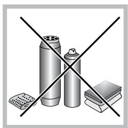
WARNING: Danger of fire: do not store items on the cooking surfaces.
WARNING: If the surface in glass-ceramic is cracked, switch off the appliance to avoid the possibility of electric shock.
Never use steam cleaners or pressure cleaners on the appliance.
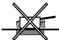
Remove any liquid from the lid before opening it. Do not close the glass cover (if present) when the gas burners or electric hotplates are still hot.
The appliance is not intended to be operated by means of an external timer or separate remote control system.
CAUTION: the use of inappropriate hob guards can cause accidents.
FR
Avertissements
J 1 J 1 J 1 J 1 J 1 J 1 J 1 J 1 J 1 J 1 J 1 J 1 J 1
i 1
a 45 j. j j j j j j j j j j j j j j j j j j j j j j j j j j j j j j j j j j j j j j j j j j j j j j j j j j j j j j j
- appliance model (Mod.)
- serial number (S/N)
This information is found on the data plate located on the appliance and/or on the packaging.
FR
Assistance
Indiquez-lui :
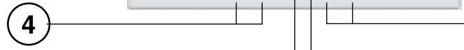
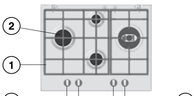
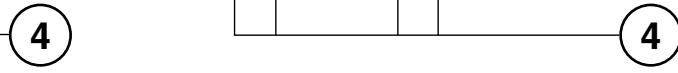
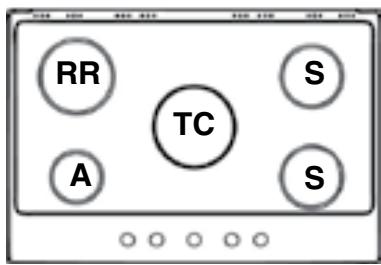
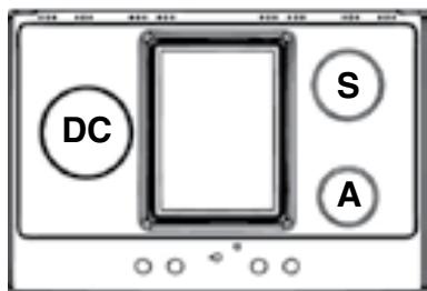
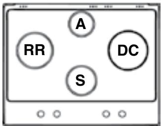
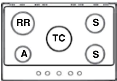
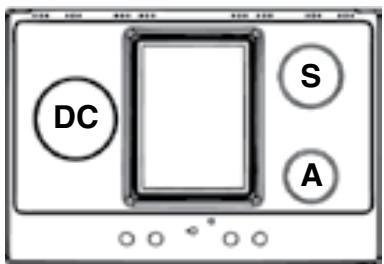
Description of the appliance
Overall view
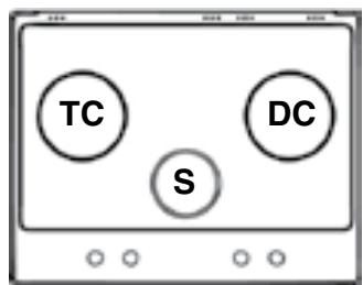
1 Support Grid for COOKWARE
2 GAS BURNERS
3 CERAMIC GLASS MODULE
4 Control Knobs for GAS BURNERS
5 INDICATOR LIGHT FOR CERAMIC GLASS MODULE*
6 Control Knobs for CERAMIC GLASS MODULE
7 Ignition for GAS BURNERS
8 SAFETY DEVICES
- The INDICATOR LIGHT for CERAMIC GLASS MODULE switches on whenever the selector knob is moved from the 'off' position.
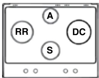
- GAS BURNERS differ in size and power. Use the diameter of the cookware to choose the most appropriate burner to cook with.
- Control Knobs for GAS BURNERS and CERAMIC GLASS MODULE* adjust the power or the size of the flame.
- GAS BURNER IGNITION* enables a specific burner to be lit automatically.
-
SAFETY DEVICE* stops the gas flow if the flame is accidentally extinguished.
-
Only available on certain models.
FR
ailll jaiall baaia * gajjial aal yall sddg jll jll
Jgj jnnn nn nnnn nn nnnn nn nnnn nn nnnn nn nnnn nn nnnn nn nnnn nn nnnn nn nnnn nn nnnn nn nnnn nn nnnn nn nnnn nn nnnn nn nnnn nn nnnn nn nnnn nn nnnn nn nnnn nn nnnn nn nnnn nn nnnn nn nnnn nn nnnn nn nnnn nn
ailll lal jai jai jai jai y** jai j
aaii jj j j

Installation
! Before operating your new appliance please read this instruction booklet carefully. It contains important information for safe use, installation and care of the appliance.
! Please keep these operating instructions for future reference. Pass them on to possible new owners of the appliance.
Positioning
!Keep packaging material out of the reach of children. It can become a choking or suffocation hazard (see Precautions and tips).
! The appliance must be installed by a qualified professional according to the instructions provided. Incorrect installation may cause harm to people and animals or may damage property.
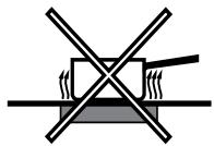
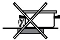
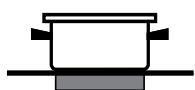
! This unit may be installed and used only in permanently ventilated rooms in accordance with current national regulations. The following requirements must be observed:
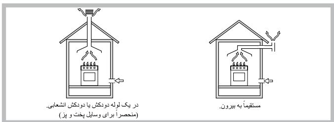
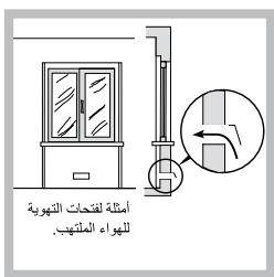
- The room must be equipped with an air extraction system that expels any combustion fumes. This may consist of a hood or an electric fan that automatically starts each time the appliance is switched on.
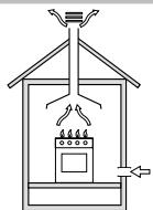
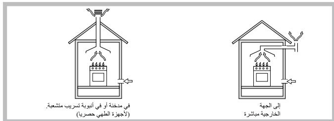
In a chimney stack or branched flue, (exclusively for cooking appliances)
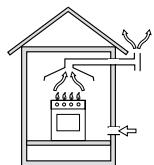
Directly to the Outside
- The room must also allow proper air circulation, as air is needed for combustion to occur normally. The flow of air must not be less than 2m^3/h per kW of installed power.
Examples of ventilation holes for combustant air.
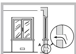
The air circulation system may take air directly from the outside by means of a pipe with an inner cross section of at least 100~cm^2 ; the opening must not be vulnerable to any type of blockages.
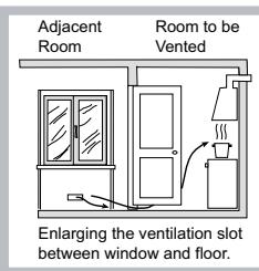
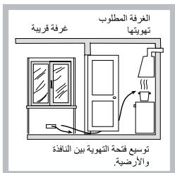
The system can also provide the air needed for combustion indirectly, i.e. from adjacent rooms fitted with air circulation tubes as described above. However, these rooms must not be communal rooms, bedrooms or rooms that may present a fire hazard.
- Liquid petroleum gas sinks to the floor as it is heavier than air. Therefore, rooms containing LPG cylinders must also be equipped with vents to allow gas to escape in the event of a leak. As a result LPG cylinders, whether partially or completely full, must not be installed or stored in rooms or storage areas that are below ground level (cellars, etc.). It is advisable to keep only the cylinder being used in the room, positioned so that it is not subject to heat produced by external sources (ovens, fireplaces, stoves, etc.) which could raise the temperature of the cylinder above 50^ .
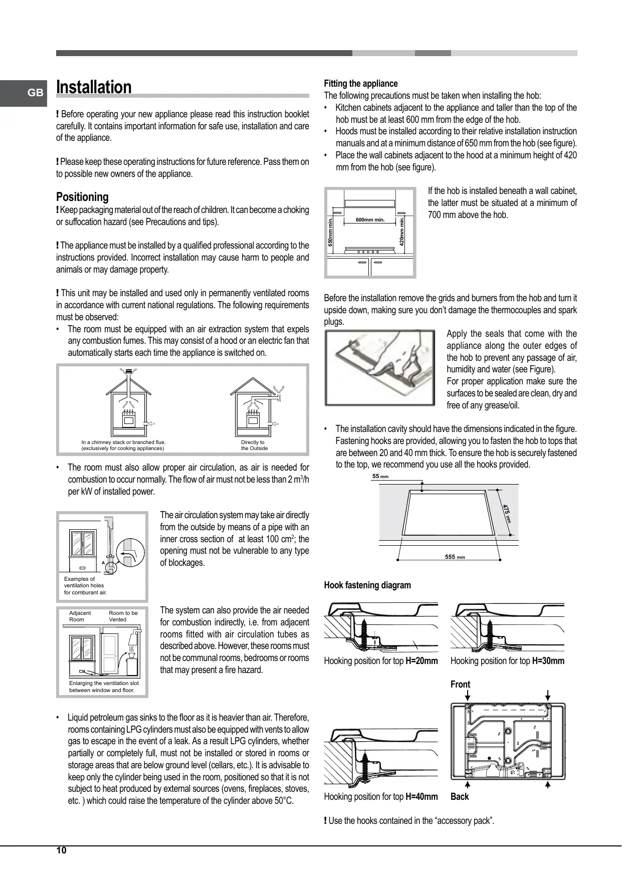
Fitting the appliance
The following precautions must be taken when installing the hob:
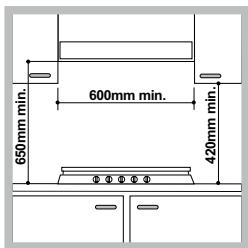
- Kitchen cabinets adjacent to the appliance and taller than the top of the hob must be at least 600mm from the edge of the hob.
- Hoods must be installed according to their relative installation instruction manuals and at a minimum distance of 650mm from the hob (see figure).
- Place the wall cabinets adjacent to the hood at a minimum height of 420 mm from the hob (see figure).
If the hob is installed beneath a wall cabinet, the latter must be situated at a minimum of 700 mm above the hob.
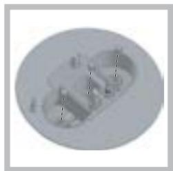
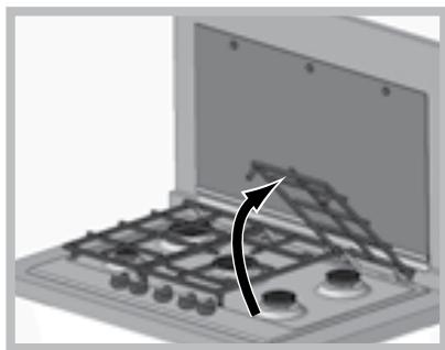
Before the installation removes the grids and burners from the hob and turn it upside down, making sure you don't damage the thermocouples and spark plugs.
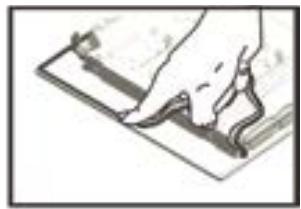
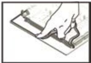
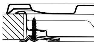
Apply the seals that come with the appliance along the outer edges of the hob to prevent any passage of air, humidity and water (see Figure).
For proper application make sure the surfaces to be sealed are clean, dry and free of any grease/oil.
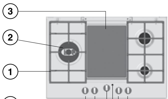
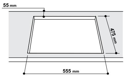
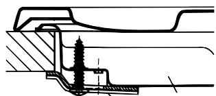
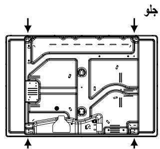
- The installation cavity should have the dimensions indicated in the figure. Fastening hooks are provided, allowing you to fasten the hob to tops that are between 20 and 40 ~mm thick. To ensure the hob is securely fastened to the top, we recommend you use all the hooks provided.

Hook fastening diagram
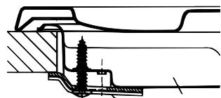
Hooking position for top H=20mm

Hooking position for top H=30mm
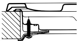
Hooking position for top H=40mm
Back
! Use the hooks contained in the "accessory pack".
- Where the hob is not installed over a built-in oven, a wooden panel must be installed as insulation. This must be placed at a minimum distance of 20mm from the lower part of the hob.
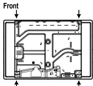
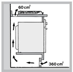
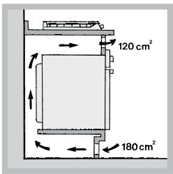
Ventilation
To ensure adequate ventilation, the back panel of the cabinet must be removed. It is advisable to install the oven so that it rests on two strips of wood, or on a completely flat surface with an opening of at least 45 × 560 mm (see diagrams).

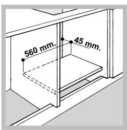
Where a hob is installed above an oven without a forced ventilation cooling system, adequate ventilation must be provided inside the cabinet by means of air holes through which air can pass (see figure).
Electrical connection
Hobs equipped with a three-pole power supply cable are designed to operate with alternating current at the voltage and frequency indicated on the data plate (this is located on the lower part of the appliance). The earth wire in the cable has a green and yellow cover. If the appliance is to be installed above a built-in electric oven, the electrical connection of the hob and the oven must be carried out separately, both for electrical safety purposes and to make extracting the oven easier.
Connecting the supply cable to the mains
Install a standardised plug corresponding to the load indicated on the data plate.
The appliance must be directly connected to the mains using an omnipolar circuit-breaker with a minimum contact opening of 3mm installed between the appliance and the mains. The circuit-breaker must be suitable for the charge indicated and must comply with current electrical regulations (the earthing wire must not be interrupted by the circuit-breaker). The supply cable must not come into contact with surfaces with temperatures higher than 50^ .
! The installer must ensure that the correct electrical connection has been made and that it is compliant with safety regulations.
Before connecting to the power supply, make sure that:
- The appliance is earthed and the plug is compliant with the law.
- The socket can withstand the maximum power of the appliance, which is indicated on the data plate.
- The voltage is in the range between the values indicated on the data plate.
- The socket is compatible with the plug of the appliance. If the socket is incompatible with the plug, ask an authorised technician to replace it. Do not use extension cords or multiple sockets.
! Once the appliance has been installed, the power supply cable and the electrical socket must be easily accessible.
! The cable must not be bent or compressed.
! The cable must be checked regularly and replaced by authorised technicians only (see Assistance).
! The manufacturer declines any liability should these safety measures not be observed.
Gas connection
The appliance should be connected to the main gas supply or to a gas cylinder in compliance with current national regulations. Before carrying out the connection, make sure the cooker is compatible with the gas supply you wish to use. If this is not the case, follow the instructions indicated in the paragraph "Adapting to different types of gas."
When using liquid gas from a cylinder, install a pressure regulator which complies with current national regulations.
! Check that the pressure of the gas supply is consistent with the values indicated in Table 1 ("Burner and nozzle specifications"). This will ensure the safe operation and longevity of your appliance while maintaining efficient energy consumption.
Connection with a rigid pipe (copper or steel)
! Connection to the gas system must be carried out in such a way as not to place any strain of any kind on the appliance.
There is an adjustable L-shaped pipe fitting on the appliance supply ramp and this is fitted with a seal in order to prevent leaks. The seal must always be replaced after rotating the pipe fitting (seal provided with appliance). The gas supply pipe fitting is a threaded 1/2 gas cylindrical male attachment.
Connecting a flexible jointless stainless steel pipe to a threaded attachment
The gas supply pipe fitting is a threaded 1/2 gas cylindrical male attachment. These pipes must be installed so that they are never longer than 2000mm when fully extended. Once connection has been carried out, make sure that the flexible metal pipe does not touch any moving parts and is not compressed.
!Only use pipes and seals that comply with current national regulations.
Checking the tightness of the connection
! When the installation process is complete, check the pipe fittings for leaks using a soapy solution. Never use a flame.
Adapting to different types of gas
To adapt the hob to a different type of gas other than default type (indicated on the rating plate at the base of the hob or on the packaging), the burner nozzles should be replaced as follows:
- Remove the hob grids and slide the burners off their seats.
- Unscrew the nozzles using a 7 mm socket spanner, and replace them with nozzles for the new type of gas (see table 1 "Burner and nozzle characteristics").
- Reassemble the parts following the above procedure in the reverse order.
- Once this procedure is finished, replace the old rating sticker with one indicating the new type of gas used. Sticker are available from any of our Service Centres.
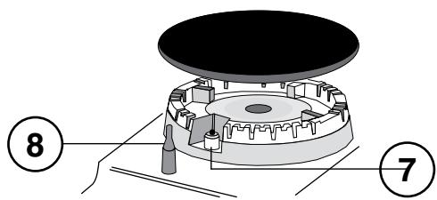
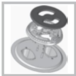
Replacing the nozzles on separate "double flame " burners
-
Remove the grids and slide the burners from their housings. The burner consists of 2 separate parts (see figure);
-
Unscrew the burers with a 7 mm wrench spanner. The internal burner has a nozzle, the external burner has two (of the same size). Replace the nozzle with models suited to the new type of gas (see table 1).
- Replace all the components by repeating the steps in reverse order.
Replacing the Triple ring burner nozzles
- Remove the pan supports and lift the burners out of their housing. The burner consists of two separate parts (see pictures).
- Unscrew the nozzles using a 7 mm socket spanner. Replace the nozzles with models that are configured for use with the new type of gas (see Table 1). The two nozzles have the same hole diameter.
- Replace all the components by completing the above operations in reverse order.
- Adjusting the burners' primary air Does not require adjusting.
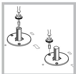
- Setting the burners to minimum
- Turn the tap to the low flame position;
- Remove the knob and adjust the adjustment screw, which is positioned in or next to the tap pin, until the flame is small but steady.
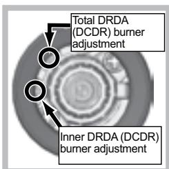
! In the event of single-control DRDA (DCDR) burners, adjustment can be performed by intervening on the 2 screws located near the tap pin (see picture).
- Having adjusted the flame to the required low setting, while the burner is alight, quickly change the position of the knob from minimum to maximum and vice versa several times, checking that the flame does not go out.
- Some appliances have a safety device (thermocouple) fitted. If the device fails to work when the burners are set to the low flame setting, increase this low flame setting using the adjusting screw.
- Once the adjustment has been made, replace the seals on the by-passes using sealing wax or a similar substance.
If the appliance is connected to liquid gas, the regulation screw must be fastened as tightly as possible.
! Once this procedure is finished, replace the old rating sticker with one indicating the new type of gas used. Stickers are available from any of our Service Centres.
! Should the gas pressure used be different (or vary slightly) from the recommended pressure, a suitable pressure regulator must be fitted to the inlet pipe (in order to comply with current national regulations).
| DATA PLATE | |
| Electrical connections | see data plate |
| CE | This appliance conforms to the following European Economic Community directives: - 2006/95/EC dated 12/12/06 (Low Voltage) and subsequent amendments - 2004/108/EC dated 15/12/04 (Electromagnetic Compatibility) and subsequent amendments - 93/68/EEC dated 22/07/93 and subsequent amendments. - 2009/142/EC dated 30/11/09 (Gas) and subsequent amendments. - 2012/19/EU and subsequent amendments. |
Burner and nozzle specifications (for 60 cm and 65 cm versions only)
| Table 1 | Liquid Gas | Natural Gas | ||||||||
| Burner | Diameter (mm) | Thermal power kW (p.c.s.* ) Reduced | Thermal power kW (p.c.s.* ) Nominal | By-pass 1/100 (mm) | Nozzle 1/100 (mm) | Flow* (g/h) | Thermal power kW (p.c.s.* ) Nominal | Nozzle 1/100 (mm) | Flow* (l/h) | |
| *** | ** | |||||||||
| Reduced Fast (RR) | 100 | 0.70 | 2.60 | 39 | 80 | 189 | 186 | 2.60 | 122 (H) | 248 |
| Semi Fast (S) | 75 | 0.40 | 1.65 | 28 | 64 | 120 | 118 | 1.65 | 96 (Y) | 157 |
| Auxiliary (A) | 55 | 0.40 | 1.00 | 28 | 50 | 73 | 71 | 1.00 | 79 (6) | 95 |
| Triple Crown (TC) | 130 | 1.50 | 3.30 | 61 | 65x2 | 240 | 236 | 3.60 | 103x2 | 343 |
| Double Flame (DCDR Internal) (2) | 36 | 0.40 | 0.90 | 27 | 44 | 65 | 64 | 0.90 | 74 | 86 |
| Double Flame (DCDR External) 2 nozzle (2) | 130 | 1.50 | 3.60 | 55 | 67x2 | 262 | 257 | 3.60 | 100x2 | 343 |
| Supply pressures | Nominal (mbar) | 28-30 | 37 | 20 | ||||||
| Minimum (mbar) | 20 | 25 | 17 | |||||||
| Maximum (mbar) | 35 | 45 | 25 | |||||||
(2) For dual-control DRDA (DCDR) burner only
At 15^ and 1013,25 mbar - dry gas
Propane P.C.S. = 50.37 MJ/Kg
** Butane P.C.S. = 49.47 MJ/Kg
Natural P.C.S. = 37.78 MJ/m³

PK630RT...
PK640R...
PK640.1R...
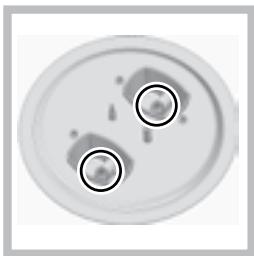
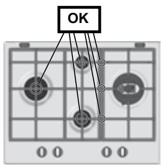
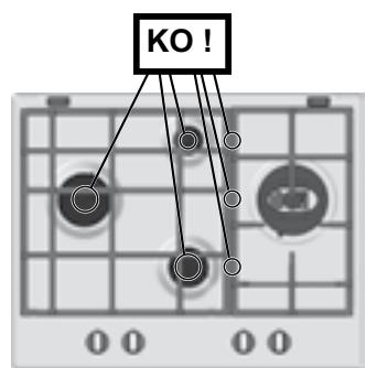
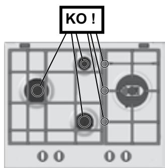
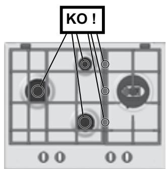
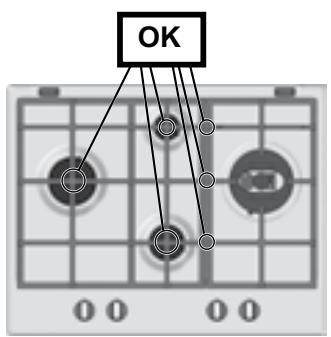
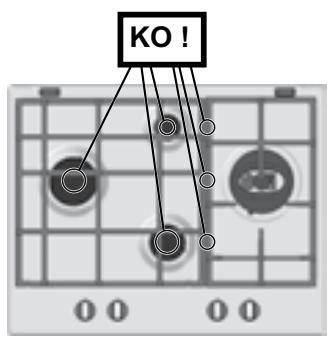
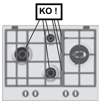
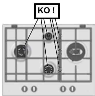
! For model PK 640.1... only: The grids may be positioned incorrectly. If this happens, the spokes will appear particularly misaligned and the intersection point will no longer be at the centre of the burner. The figures below illustrate correct positioning (OK) and some examples of incorrect positioning (KO!).
Burner and nozzle specifications (for 75 cm versions only)
| Table 1 | Liquid Gas | Natural Gas | ||||||||
| Burner | Diameter (mm) | Thermal power kW (p.c.s.*) Reduced | Thermal power kW (p.c.s.*) Nominal | By-pass 1/100 (mm) | Nozzle 1/100 (mm) | Flow* (g/h) | Thermal power kW (p.c.s.*) Nominal | Nozzle 1/100 (mm) | Flow* (l/h) | |
| *** | ** | |||||||||
| Reduced Fast (RR) | 100 | 0.70 | 2.60 | 39 | 80 | 189 | 186 | 2.60 | 122 (H) | 248 |
| Semi Fast (S) | 75 | 0.40 | 1.65 | 28 | 64 | 120 | 118 | 1.65 | 96 (Y) | 157 |
| Auxiliary (A) | 55 | 0.40 | 1.00 | 28 | 50 | 73 | 71 | 1.00 | 79 (6) | 95 |
| Triple Crown (TC) | 130 | 1.50 | 3.30 | 61 | 65x2 | 240 | 236 | 3.60 | 103x2 | 343 |
| Double Flame (DCDR Internal) (2) | 36 | 0.40 | 0.90 | 28 | 44 | 65 | 64 | 0.90 | 74 | 86 |
| Double Flame (DCDR External) 2 nozzle (2) | 130 | 1.50 | 4.10 | 61 | 70x2 | 298 | 293 | 4.10 | 110x2 | 390 |
| Supply pressures | Nominal (mbar) | 28-30 | 37 | 20 | ||||||
| Minimum (mbar) | 20 | 25 | 17 | |||||||
| Maximum (mbar) | 35 | 45 | 25 | |||||||
(2) For dual-control DRDA (DCDR) burner only
At 15^ and 1013,25 mbar - dry gas
**
Propane P.C.S. = 50.37 MJ/Kg
***
Butane P.C.S. = 49.47 MJ/Kg
Natural P.C.S. = 37.78 MJ/m³
PK750T...
PK741RQO...
Start-up and use
! The position of the corresponding gas burner or electric hotplate* is shown on every knob.
Gas cooker hobs are equipped with discrete power adjustment that allows for accurately adjusting the flame to 5 different power levels. Thanks to this system, gas hobs are also capable of guaranteeing the same cooking results for each recipe, as the optimal power level for the desired type of cooking can be identified in an easier, more accurate way.
Gas burners
Each burner can be adjusted to one of the following settings using the corresponding control knob:

Off
Maximum

Minimum
To light one of the burners, hold a lit match or lighter near the burner and, at the same time, press down and turn the corresponding knob anti-clockwise to the maximum setting.
Since the burner is fitted with a safety device, the knob should be pressed for approximately 2-3 seconds to allow the automatic device keeping the flame alight to heat up.
When using models with an ignition button, light the desired burner pressing down the corresponding knob as far as possible and turning it anticlockwise towards the maximum setting.
! If a flame is accidentally extinguished, turn off the control knob and wait for at least 1 minute before trying to relight it.
To switch off the burner, turn the knob in a clockwise direction until it stops (when reaches the "●" position).
Discrete flame adjustment
The selected burner can be adjusted - by means of the knob - to 5 different power levels. To shift between levels, simply turn the knob towards the desired power level.
A click signals the passage from one power level to the other.
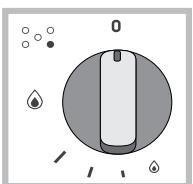
The selected power level is indicated by the corresponding symbol (symbols). The system guarantees accurate flame adjustment and uniform cooking results by facilitating selection of the desired power level.
The "double-flame" burner
This gas burner consists of two concentric flame rings that can operate jointly or independently (in case of dual-control only).
As the burner is fitted with a safety device, the knob should be pressed down for approximately 2-3 seconds until the device keeping the flame automatically alight heats up.
Dual control:
Each ring comprising the burner has its own control knob:
The knob marked with the symbol controls the outer ring.
The knob marked with the symbol controls the inner ring.
To activate any one of the two rings, press the corresponding knob and turn
it anti-clockwise to the maximum power setting

In order to use the double-flame burner to its full potential, avoid simultaneously setting the inner ring to minimum power and the outer ring to maximum power.
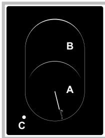
Ceramic Glass Module*
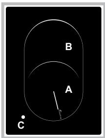
This cooktop is fitted with dual-ring radiant heating elements located beneath the glass. It is possible to turn on only the circular part of the element (identified by the letter “A”) or the cooking surface can be enlarged by tuming on both “A” and “B”. To turn only the circular “A” element, simply turn the knob in the clockwise direction to any one of the 12 available settings. To add the “B” section, turn
the knob to setting 12 and then click it into the setting. Then proceed by turning the knob in the counter-clockwise direction to one of the 12 settings. The figure shows the heating zones, which become red when the element is turned on.
A. Circular heating zone;
B. Extended heating zone;
C. Indicator light to show when the cooking zone is above 60^ , even after the heating element has been turned off.
When the knob is on any of the settings other than "Off", the Indicator Light for Ceramic Glass Module comes on.
Practical advice on using the burners
To ensure the burners operate efficiently:
- Use appropriate cookware for each burner (see table) so that the flames do not extend beyond the bottom of the cookware.
Always use cookware with a flat base and a cover. - When the contents of the pan reach boiling point, turn the knob to minimum.
Pans to be used on 60 - 65 cm hobs
| Burner | Ø Cookware diameter (cm) |
| Reduced Rapid (RR) | 24 - 26 |
| Semi Rapid (S) | 16 - 20 |
| Auxiliary (A) | 10 - 14 |
| Triple Crown (TC) | 24 - 26 |
| Double Flame (DCDR internal) | 10 - 14 |
| Double Flame (DCDR external) | 24 - 26 |
Pans to be used on 75 cm hobs
| Burner | Ø Cookware diameter (cm) |
| Reduced Rapid (RR) | 24 - 26 |
| Semi-Rapid (S) | 16 - 20 |
| Auxiliary (A) | 10 - 14 |
| Triple Crown (TC) | 24 - 26 |
| Double Flame (DCDR internal) | 10 - 14 |
| Double Flame (DCDR external) | 26 - 28 |
! On the models supplied with a reducer shelf, remember that this should be used only for the Double flame internal (DCDR internal) burner when you use casserole dishes with a diameter under 12 cm.
- Only available on certain models.
To identify the type of burner, refer to the designs in the section entitled, "Burner and Nozzle Specifications".
Practical Advise on Using the Ceramic Glass Module*
| Set. | Radiant Burner |
| 0 | Off. |
| 1 | To melt butter and chocolate. |
| 2 | To heat liquids. |
| 3 | |
| 4 | For creams and sauces. |
| 5 | |
| 6 | For cooking at the boiling point. |
| 7 | |
| 8 | For Roasts. |
| 9 | |
| 10 | For boiling large pieces of meat. |
| 11 | |
| 12 | For frying. |
| For utilising both cooking areas. |
To obtain the best results from your hob:
- Use flat-bottomed pans to ensure that they adhere to the cooking zone perfectly.
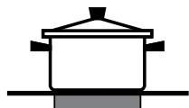
- Always use pans with a diameter that is large enough to cover the hotplate fully, in order to use all the available heat.
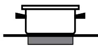
- Make sure that the bottom of the cookware is always dry and clean to guarantee correct adherence and long life, not only for the cooking zones but also for the cookware itself.
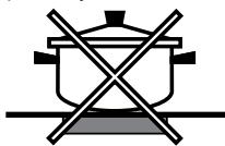
- Avoid using the same cookware that is used on gas burners: the heat concentration on gas burners may deform the base of the pan, causing it not to adhere correctly.
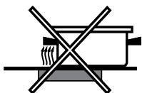
- Never leave a cooking zone on without cookware on it because as it heats up and rapidly reaches the maximum level, which could damage the heating elements.
! There might be traces of grease left by the glue used to seal the glass which should be removed before using the appliance with a mild cleaning product. During the first few hours of use you might smell rubber but this will disappear quickly.
Precautions and tips
! This appliance has been designed and manufactured in compliance with international safety standards. The following warnings are provided for safety reasons and must be read carefully.
General safety
This is a class 3 built-in appliance.
- Gas appliances require regular air exchange to maintain efficient operation. When installing the hob, follow the instructions provided in the paragraph on "Positioning" the appliance.
- These instructions are only valid for the countries whose symbols appear in the manual and on the serial number plate.
- The appliance was designed for domestic use inside the home and is not intended for commercial or industrial use.
- The appliance must not be installed outdoors, even in covered areas. It is extremely dangerous to leave the appliance exposed to rain and storms.
- Do not touch the appliance with bare feet or with wet or damp hands and feet.
- The appliance must be used by adults only for the preparation of food, in accordance with the instructions outlined in this booklet. Any other use of the appliance (e.g. for heating the room) constitutes improper use and is dangerous. The manufacturer may not be held liable for any damage resulting from improper, incorrect and unreasonable use of the appliance.
- Ensure that the power supply cables of other electrical appliances do not come into contact with the hot parts of the oven.
- The openings used for ventilation and dispersion of heat must never be covered.
Always make sure the knobs are in the "●"/"○" position when the appliance is not in use.
- When unplugging the appliance always pull the plug from the mains socket, do not pull on the cable.
- Never carry out any cleaning or maintenance work without having detached the plug from the mains.
- In case of malfunction, under no circumstances should you attempt to repair the appliance yourself. Repairs carried out by inexperienced persons may cause injury or further malfunctioning of the appliance. Contact a Service Centre (see Assistance).
- Always make sure that pan handles are turned towards the centre of the hob in order to avoid accidental burns.
- Do not close the glass cover (if present) when the gas burners or electric hotplates are still hot.
- Do not leave the electric hotplate switched on without a pan placed on it.
- Do not use unstable or deformed pans.
- The appliance should not be operated by people (including children) with reduced physical, sensory or mental capacities, by inexperienced individuals or by anyone who is not familiar with the product. These individuals should, at the very least, be supervised by someone who assumes responsibility for their safety or receive preliminary instructions relating to the operation of the appliance.
- Do not let children play with the appliance.
- The appliance is not intended to be operated by means of an external timer or separate remote-control system.
Disposal
- When disposing of packaging material: observe local legislation so that the packaging may be reused.
-
The European Directive 2012/19/EU on Waste Electrical and Electronic Equipment (WEEE), requires that old household electrical
-
Only available on certain models.
appliances must not be disposed of in the normal unsorted municipal waste stream. Old appliances must be collected separately in order to optimise the recovery and recycling of the materials they contain and reduce the impact on human health and the environment. The crossed out "wheeled bin" symbol on the product reminds you of your obligation, that when you dispose of the appliance it must be separately collected.
Consumers should contact their local authority or retailer for information concerning the correct disposal of their old appliance.
Maintenance and care
Switching the appliance off
Disconnect your appliance from the electricity supply before carrying out any work on it.
Cleaning the appliance
! Do not use abrasive or corrosive detergents such as stain removers, anti-rust products, powder detergents or sponges with abrasive surfaces: these may scratch the surface beyond repair.
! Never use steam cleaners or pressure cleaners on the appliance.
- It is usually enough to wash the hob with a damp sponge and dry it with absorbent kitchen roll.
- The removable parts of the burners should be washed frequently with warm water and soap and any burnt-on substances removed.
- For hobs which lighth automatically, the terminal part of the electronic instant lighting devices should be cleaned frequently and the gas outlet holes should be checked for blockages.
- Before using the ceramic glass module, the surface must be cleaned, using a damp cloth to remove dust or food residues. The ceramic glass surface should be cleaned regularly with a solution of warm water and a non-abrasive detergent.
Periodically, special products will need to be used to clean the surface. First, remove all food buildup or grease with a cleaning scraper, e.g. CERAL (not supplied).
Clean the cooking surface when it is still warm with a suitable cleaning product (such as the one in the Solutions product line available from any After-Sales Service
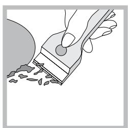
Centre) and paper towels. Then rub with a damp cloth and dry. Aluminum foil, plastic items, objects made of synthetic material, sugar or foods with a high sugar content that have melted onto the surface must be removed immediately with a scraper while the cooking surface is still hot.
Special cleaning products for ceramic glass surfaces form a transparent protective layer which fights dirty buildup. This also protects the surface from damage caused by food with a high sugar content. Do not use abrasive sponges or cleaning products under any circumstances. This holds true for chemically aggressive cleaners, like oven sprays and stain removers.
- Stainless steel can be marked by hard water that has been left on the surface for a long time, or by aggressive detergents containing phosphorus. After cleaning, rinse and dry any remaining drops of water.
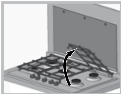
! It is not necessary to remove the pan supports in order to clean the hob surface. Thanks to the support system, simply lift and hold the pan supports or rotate them until they rest against a rear support.
Do not place the hot grids on top of the glass cover (if applicable), otherwise the rubber plugs on the glass may be damaged.
Gas tap maintenance
Over time, the taps may become jammed or difficult to turn. If this happens, the tap must be replaced.
! This procedure must be performed by a qualified technician authorised by the manufacturer.
Troubleshooting
It may happen that the appliance does not function properly or at all. Before calling the service centre for assistance, check if anything can be done. First, check to see that there are no interruptions in the gas and electrical supplies, and, in particular, that the gas valves for the mains are open.
The burner does not light or the flame is not even around the burner. Check whether:
The gas holes on the burner are clogged.
- All the movable parts that make up the burner are mounted correctly.
There are draughts near the appliance.
The flame dies in models with a safety device.
Check to make sure that:
- You pressed the knob all the way in.
- You keep the knob pressed in long enough to activate the safety device.
- The gas holes are not blocked in the area corresponding to the safety device.
The burner does not remain lit when set to minimum.
Check to make sure that:
The gas holes are not blocked.
There are no draughts near the appliance.
The minimum setting has been adjusted properly.
The cookware is unstable.
Check to make sure that:
- The bottom of the cookware is perfectly flat.
- The cookware is positioned correctly at the centre of the burner.
The pan support grids have been positioned correctly.
Installation
J 1 J 1 J 1 J 1 J 1 J 1 J 1 J 1 J 1 J 1 J 1 J 1 J 1 J 1 J 1 J 1 J 1 J 1 J 1 J 1 J 1 J 1 J 1 J 1 J 1 J 1 J 1 J 1 J 1 J 1 J 1 J 1 J 1 J 1 J
1234567890123456789012345678901234567890123456789012345678901234567890123456789012345678901234567890123456789
Jus
.
(s)
152 152
1/2 1/2
Cui j0jS
Jg jn Jn 4y g y dy n nn ane aag
1/2 j 1/2
2000 j 1 1 1 1 1 1 1 1 1 1 1 1 1 1 1 1 1 1 1 1 1 1 1 1 1 1 1 1 1 1 1 1 1 1
a
aJg jI JI JI JI JI JI JI JI JI JI JI JI JI
Jus
J 1
i 1
i:la jil s jiu jil
J 1 J 1 J 1 J 1 J 1 J 1 J 1 J 1 J 1 J 1 J 1 J 1 J 1 J 1 J 1 J 1 J 1 J 1 J 1 J 1 J 1 J 1 J 1 J 1 J 1 J 1 J 1 J 1 J 1 J 1 J 1 J 1 J 1 J 1 J
Jy
3 3 3 3 3 3 3 3 3 3 3 3 3 3 3 3 3 3 3 3 3 3 3 3 3 3 3 3 3 3 3 3 3 3 3 3 3 3 3 3 3 3 3 3 3 3 3 3 3 3 3
i 1
y
.
15 24
.
jSg jdi dSd Sd Sd Sd Sd Sd Sd Sd Sd Sd Sd Sd Sd Sd Sd Sd Sd Sd
41 1 J oJ 00000000000000000000000000000000000000000000000000000000000
b1 = 4 b2 = 0
aS a buaa jiaba a Joc a J 1 1 1 1 1 1 1 1 1 1 1 1
i
y
4y 1 y j 1 j 1 j 1 j 1 j 1 j 1 j 1 j 1 j 1 j 1 j 1 j 1 j 1 j 1 j 1 j 1 j 1 j 1 j 1 j 1 j 1 j 1 j 1 j 1 j 1 j 1 j 1 j 1 j 1 j 1 j 1 j 1 j 1 j 1
- a5 = a6 + 3d a_5 = 32
L
H=30mm
H=20mm


H=40mm 2

FA
B.S.6891 B.S.6172/B.S.5440.Par.2:
:dydyj jy j y j y j y j j.
a
J 1
218 = 2
j 5 j j j j j j j j j j j j j j j j j j j j j j j j j j j j j j j j j j j j j j
1 2
\*
12 j 12 j 12 j 12 j 12 j 12 j 12 j 12 j 12 j 12 j 12 j 12 j 12 j 12 j 12 j 12 j 12 j 12 j 12 j 12 j 12 j 12 j 12 j 12 j 12 j 12 j

A
Aiyaiyaiyaiyaiyaiyaiyaiyaiyaiyaiyaiyaiyaiyaiyaiyaiyaiyaiyaiyaiyaiyaiyaiyaiyaiyaiyaiyaiyaiyaiyaiyaiyaiyaiyaiyaiyaiyaiyaiyaiyaiyaiyaiyaiyaiyaiyaiyaiyaiyaiyai
4y 4y 4y 4y 4y 4y 4y 4y 4y 4y 4y 4y 4y 4y 4y 4y 4y 4y 4y 4y 4y 4y 4y 4y
"golis" j 10000000000000000000000000000000000000000000000000
la ala jolaloljglas 4
la aai jydo yLac uanai (y)
j j 11111111111111111111111111111111111111111111111
| (سالميَفَس) مطْفَلِهُ | شامع |
| 24 - 26 | (RR) صَمَسَسَيرَب |
| 16 - 20 | (S) نَمَسَرْب |
| 10 - 14 | (A) صَسَسَسَسَسَسَسَسَسَسَسَسَسَسَسَسَسَسَسَسَسَسَسَسَسَسَسَسَسَسَسَسَسَسَسَسَسَسَسَسَسَسَسَسَسَسَسَسَسَسَمَسَسَسَسَسَسَسَسَسَسَسَسَسَسَسَسَسَسَسَسَسَسَسَسَسَسَسَسَسَسَسَسَسَسَسَسَسَسَسَسَسَسَسَسَسَسَسَسَسَفَلَدْ |
| 24 - 26 | (TC) صَمَسَسَمَسَسَسَسَسَسَسَسَسَسَسَسَسَسَسَسَسَسَسَسَسَسَسَسَسَسَسَسَسَسَسَسَسَسَسَسَسَسَسَسَسَسَسَسَسَسَمَسَسَمَسَسَسَسَسَسَسَسَسَسَسَسَسَسَسَسَسَسَسَسَسَسَسَسَسَسَسَسَسَسَسَسَسَسَسَسَسَسَسَسَسَسَسَسَسَمَسَسَسَمَسَسَسَسَسَسَسَسَسَسَسَسَسَسَسَسَسَسَسَسَسَسَسَسَسَسَسَسَسَسَسَسَسَسَسَسَسَسَسَسَسَسَسَسَسَمَمَسَسَسَسَسَسَسَسَسَسَسَسَسَسَسَسَسَسَسَسَسَسَسَسَسَسَسَسَسَسَسَسَسَسَسَسَسَسَسَسَسَسَسَسَسَسَسَسَمَمَسَسَمَسَسَسَسَسَسَسَسَسَسَسَسَسَسَسَسَسَسَسَسَسَسَسَسَسَسَسَسَسَسَسَسَسَسَسَسَسَسَسَسَسَسَسَسَسَs65-60-60-60-60-60-60-60-60-60-60-60-60-60-60-60-60-60-60-60-60-60-60-60-60-60-60-60-60-60-60-60-60-60-60 - 60 - 60 - 60 - 60 - 60 - 60 - 60 - 60 - 60 - 60 - 60 - 60 - 60 - 60 - 60 - 60 - 60 - 60 - 60 - 60 - 60 - 60 - 60 - 60 - 60 - |
| (سالميَفَس) مطْفَلِهُ | شامع |
| 24 - 26 | (RR) صَمَسَسَمَسَسَمَسَسَمَسَسَمَسَسَمَسَسَمَسَسَمَسَسَمَسَسَمَسَسَمَسَسَمَسَسَمَسَسَمَسَسَمَسَسَمَسَسَمَسَسَمَمَسَمَسَسَمَسَسَمَسَسَمَسَسَمَسَسَمَسَسَمَسَسَمَسَسَمَسَسَمَسَسَمَسَسَمَسَسَمَسَسَمَسَسَمَسَسَمَسَسَm— |
| 16 - 20 | (S) صَمَسَسَمَسَسَمَسَسَمَسَسَمَسَسَمَسَسَمَسَسَمَسَسَمَسَسَمَسَسَمَسَسَمَسَسَمَسَسَمَس— |
| 10 - 14 | (A) صَس—" |
| 24 - 26 | (TC) صَمَسَمَس— |
| 10 - 14 | (DCDR) صَمَسَمَس— |
| 26 - 28 | (DCDR) صَمَسَمَس— |
75jg jg 83
1
1 5 5 5 5 5 5 5 5 5 5 5 5 5 5 5 5 5 5 5 5 5 5 5 5 5 5 5 5 5 5 5 5 5 5 5 5 5 5 5 5 5 5 5 5 5 5 5 5 5 5 4
j5
j 1 j j j j j j j j j j j j j j j j j j j j j j j j j j j j j j j j j j j j j
gol
j51

J12

L 1 L 1 L 1 L 1 L 1 L 1 L 1 L 1 L 1 L 1 L 1 L 1 L 1 L 1 L 1 L 1 L 1 L 1 L 1 L 1 L 1 L 1 L 1 L 1 L 1 L 1 L 1 L 1 L 1 L 1 L 1 L 1 L 1 L 1 L
3 2 1 1 1 1 1 1 1 1 1 1 1 1 1 1 1 1 1 1 1 1 1 1 1 1 1 1 1 1 1 1 1 1 1 1 1 1 1 1 1 1 1
C 1
(6jiailw 65g jyijilw 60 gla Jla yj k) JJg dai chia
J 1 J 1 J 1 J 1 J 1 J 1 J 1 J 1 J 1 J 1 J 1 J 1 J 1 J 1 J 1 J 1 J 1 J 1 J 1 J 1 J 1 J 1 J 1 J 1 J 1 J 1 J 1 J 1 J 1 J 1 J 1 J 1 J 1 J 1 J
()CERA (204
Sg 100000000000000000000000000000000000000000000000000000
S ACD = S COD + S BDO - S CDA
Jgai jai jia jua jia jia jia jia jia jia jia

a a a a a a a a a a a a a a a a a a a a a a a a
auiuuii iuiiuiuiuiuiuiuiuiuiuiuiuiuiuiui
i
olusnsds
1j j 000000000000000000000000000000000000000
0
y j 1
a
1
J 1 J 1
yds yds yds yds
a 1
aee baa 5 jjoojj jayaaas yss good aal as alalolal
aLd 1
J 1
21
ydsd 10000000000000000000000000000000000000000000000000000000000
JSLjLcLw jLgBjLgSjLjIjIyOoOyOyOyOyOyOyOy
a
#
J 1
aaiy aaii 1
S
3 15s jgsol
jai piia iia. iuaa uuaia gaa jai da jaii dusd aas yjg jyj
i 1 j 1 o 1 1 1 1 1 1 1 1 1 1
4a 1
a
a a a a a a a a a a a a a a a a a a a a
jai
a a a a a a a a a a a a a a a a a a a
50 50
Lg 1
aai 1
j 100
jlll jdi liaiyiaea i jla
ailll llll llll lllllllll
L
jla gis jn nlll, jall aal lal gaaalld jy 1d . jgaiiiaaiaa
aal aal alal lal 10
Jusll Jssllnssy
-
-
-
-
-
-
-
-
-
-
-
-
-
-
-
-
- 1.
-
-
-
-
-
-
-
-
-
-
-
-
-
-
-
j
:J 1
e jlln jj j j jlll j j j j j j j j j
600 2
ailllll lllllllllllllllllllllllllllll
B.S.6891, B.S.6172/B.S.5440:
ailll lllbially
jay jyiaai aai ayj yaj yagai gaiyai yaiyai yaiyai yaiyai
jlll jlll lgl y 100
a 1
aalaaalaln a b y s lslcwlj 2 no jol glll
100 11 12 13 14 15 16 17 18 19 20
.
aayy 1 ygill gll yddill b
biolily
i 1
aiaaa aee aee aee aee aee aee aee aee aee aee aee aee aee aee aee aee
a 1
buae Jaua (s) jaa Jaua 1.4
jll jll
Aeguaa 1 Jjell aagaaeauuul u jgall uuiuie pueaaln aegaii 5
jSaj jbiwll jaiu kla! jdi jiljia jzjjl jslij
Jn aiee ann nnnn ennnnne eannnnn neennnnnne
aaii jia jia jia jia iiaaiial aie Ujuaaiy.
yj yj yj yj yj yj yj yj yj yj yj yj yj yj yj yj yj yj yj yj yj yj yj yj yj yj yj yj yj yj yj yj yj yj yj yj yj
(1)
AR
g j 1
jkaal jajl jai jai jai jai jai jai jai jai jai jai jai jai jai jai jai jai jai jai jai jai jai jai jai jai jai jai jai jai jai jai jai jai jai jai jai jai jai jai jai jai jai jai jai jai jai jai jai jai jai jai jali jali jali jali jali jali jali jali jali jali jali jali jali jali jali jali jali jali jali jali jali jali jali jali jali jali jali jali jali jali jali jali jali jali jali jali jali jali jali jali jali jali jali jali jali jali jali jali jali jali
jai jia jiall jia jiali
Jg jyj (Jzjj) j 1
cblc
aLiLi aLiLi aLiLi aLiLi aLiLi
| (مَس) مطْعْدُ الحَلِيَ بَعْدُ | معربي |
| 24-26 | (RR) صَبْعْدُ الحَلِيَ بَعْدُ |
| 16-20 | (S) صَبْعْدُ |
| 10-14 | (A) صَبْعْdُ |
| 24-26 | (TC) صَبْعْدُ |
| 10-14 | (الحَبْدُ DCDR) صَبْعْدُ |
| 24-26 | (الحَبْدُ DCDR) صَبْعْdُ |
| 65-60 مَسَنَسَنَسَنَسَنَسَنَسَنَسَنَسَنَسَنَسَنَسَنَسَنَسَنَسَنَسَنَسَنَسَنَسَنَسَنَسَنَسَنَسَنَسَنَسَنَسَنَسَнَسَنَسَنَسَنَسَنَسَنَسَنَسَنَسَنَسَنَسَنَسَنَسَنَسَنَسَنَسَنَسَنَسَنَسَنَسَنَسَنَسَنَسَنَسَنَسَنَسَnَسَنَسَنَسَnَسَnَسَnَسَnَسَnَسَnَسَnَسَnَسَnَسَnَسَnَسَnَسَnَسَnَسَnَسَnَسَnَسَnَسَnَسَnَسَnَسَnَسَnَسَnَسَnَسَs | |
| (مَس) مطْعْدُ الحَلِيَ بَعْدُ | مazersف惕 |
| 24-26 | (RR) صَبْعْدُ الحَلِيَ بَعْدُ |
| 16-20 | (S) صَبْعْdُ |
| 10-14 | (A) صَبْعْdُ |
| 24-26 | (TC) صَبْعْdُ |
| 10-14 | (الحَبْdُ DCDR) صَبْعْdُ |
| 26-28 | (الحَبْdُ DCDR) صَبْعْdُ |
15 75
g 12 n 12n 12n 12n 12n 12n 12n 12n 12n 12n 12n 12n 12n 12n 12n 12n 12n 12n 12n 12n 12n 12n 12n 12n 12n 12n 12
a
L 1
5 5 5 5 5 5 5 5 5 5 5 5 5 5 5 5 5 5 5 5 5 5 5 5 5 5 5 5 5 5 5 5 5 5 5 5 5 5 5 5 5 5 5 5 5 5 5 5 5 5 5
jai j
aal aal alal alal alal alal alal alal alal alal
Aolai 1 a
(“”)gglgglgglg) 1
y
5 5
allll lalll sioo ool y llll o joi oaii
aaiy
jssll) 4d jssll jssll jcc dall aal lal y
11
aallll aal lss
"zjzjzjj111
a aalaaalbauuuaa aalaaal aalaaal
aaii aaii ai iiaai
aaiy jj yj
PK630RT...
PK640R...
PK640.1R...
PK750T...
PK741RQO...
P 640.1... jlll
.(KO!)
e 1 1 1 1 1 1 1 1 1 1 1 1 1 1 1 1 1 1 1 1 1 1 1 1 1 1 1 1 1 1 1 1 1 1 1
aal aal
- jsl 1
.
J
Jr
jai jao jao jai jai jai jai jai jai jai jai jai jai jai jai jai jai jai jai jai jai jai jai jai jai jai jai jai jai jai jai jai jai jai jai jai jai jai jai jai jai jai
:J 05
Jaliljulil
JJI JJIJIJIJIJIJIJIJIJIJIJIJIJIJIJIJIJIJIJIJIJIJIJIJIJIJIJIJIJIJIJIJIJIJIJIJIJIJIJIJIJIJIJIJIJIJIJIJIJIJIJIJIJIJIJIJIJIJIJIJIJIJIJIJIJIJIJIJIJIJIJIJIJIJIJIJIJIJIJIJIJIJIJIJIJIJIJIJIJIJIJIJIJIJIJIJIJIJIJIJIJ
jai jia gai jia gill aiaial gai yie jaiy
#
:J 05
.
AilSa jiaaa jiebll
:j 15
lalaiabungebali elijxsc
Jss Jssssssssssssssssssssssssssssss
Jauuue aae aee
jglal go biizally ckiial g jzily ckiial 1
Aolaoa aalldaiyiaajgiabjraaiuulipduiu yll Jussele
j 1000000000000000000000000000000000000000
laic aaiall algal all j
a b
a
J 1 J 1 J 1 J 1 J 1 J 1 J 1 J 1 J 1 J 1 J 1 J 1 J 1 J 1 J 1 J 1 J 1 J 1 J 1 J 1 J 1 J 1 J 1 J 1 J 1 J 1 J 1 J 1 J 1 J 1 J 1 J 1 J 1 J 1 J
(2) = ( x1,y1) , = ( x2,y2)
aaiy i 10000000000000000000000000000000000000000000000000000000000000000
Aaalalalalalalalalalalalalalalalalalal
yie 1
i
jiaai jiai jia
aaiiilllll llllllll lllllllllllllllllllllllllllllllllllllll
aaii aiai iiai iiaiaiaiaiaia
aalell aegill
aaii iiaaiy
AR
J 3 jj j j
aaii i 1
jll"
a a a a a a a a a a a a a a a a a a a a a a a a
Glllgljll Jauuuiuui jy g ujjial jls juiuuiuui jjai
12 jbiin jbiin biin jbiin gdi jki jgi jjia jjia jjia jjia jjia jjia
alglgellillllglj
y
a 1
i j 1
aaln aiee eae ee eae ae eae ae eae ae ae ae ae ae ae ae ae ae ae ae ae ae ae ae ae ae ae ae ae ae ae ae ae ae ae ae ae ae ae ae ae ae ae ae ae ae ae ae ae ae ae ae ae ae ae ae ae ae ae ae ae ae ae ae ae ae ae ae ae ae ae ae ae ae ae ae ae ae ae ae ae ae ae ae ae ae ae ae ae ae ae ae aaee
1
a a a a a a a a a a a a a a a a a a a a a a a
Jgll JkJyJgJgJgJgJg
a a a a a a a a a a a a a a a a a a a a a a
Aiiiai ciil j lo iaiiai joi all oji si laisi (a) 1
aasall jaaannn aaii
a a a a a a a a a a a a a a a a a a a a a a a a a a a a a a a a a a a a a a a a a a
jlll lssuul aalaiy ay jle Jusall
J 1
#
a 2012/19/EU
e (WEEE)
aiee eae aee
a 1 a 1 1 1 1 1 1 1 1 1 1 1 1 1 1 1 1 1 1 1 1 1 1 1 1 1 1 1 1 1 1 1
b2 = 12,b3 = - 18,b_4 = 116
gaiy jie 0jai jai y aal gai bai jai jai
aill jie jn aalll lall ay bally alld