
PRF0120497 - Range hood ELICA - Free user manual and instructions
Find the device manual for free PRF0120497 ELICA in PDF.


| Product Type | Range hood |
| Brand | Elica |
| Model | PRF0120497 |
| Dimensions (W x D x H) | 60 x 30 x 50 cm |
| Net weight | 12 kg |
| Power supply | 220-240 V, 50/60 Hz |
| Motor power | 200 W |
| Maximum airflow | 650 m³/h |
| Noise level | 55 dB (A) |
| Mounting type | Wall-mounted |
| Grease filter | Dishwasher-safe aluminum |
| Charcoal filter | Optional, recommended replacement every 6 months |
| Lighting | LED, 2 x 3 W |
| Number of speeds | 3 |
| Control | Push buttons |
| Material | Stainless steel |
| Energy class | A |
| Main functions | Suction, extraction or recirculation, lighting |
| Maintenance and cleaning | Clean grease filters regularly, wipe surface with a soft cloth |
| Safety | Automatic delayed shut-off |
| Spare parts available | Filters, bulbs, remote control |
Frequently Asked Questions - PRF0120497 ELICA
User questions about PRF0120497 ELICA
0 question about this device. Answer the ones you know or ask your own.
Ask a new question about this device
Download the instructions for your Range hood in PDF format for free! Find your manual PRF0120497 - ELICA and take your electronic device back in hand. On this page are published all the documents necessary for the use of your device. PRF0120497 by ELICA.
USER MANUAL PRF0120497 ELICA
EN Instruction on mounting and use
1-2-3-4-5-6-7-8-9- 10-11-12-13-14-15- 16-17-18-19-20-21- 22-28

4-5-6-7-23a-24-25a- 26a-27-28 4-5-6-7-23b-24-25b- 26b-27-28


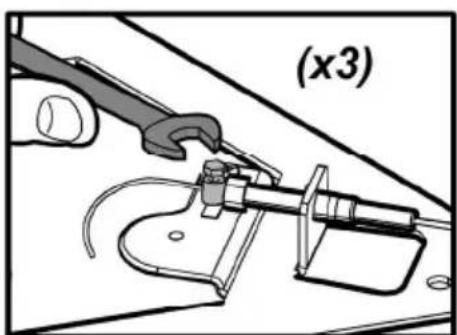
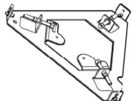
2


3
3.4


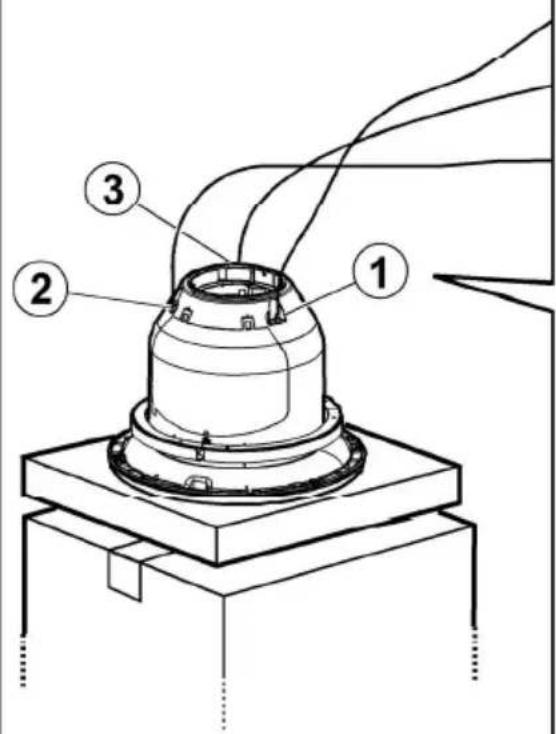
9
9.1
9.2

9.3

x3

9.4
9.5 9.6
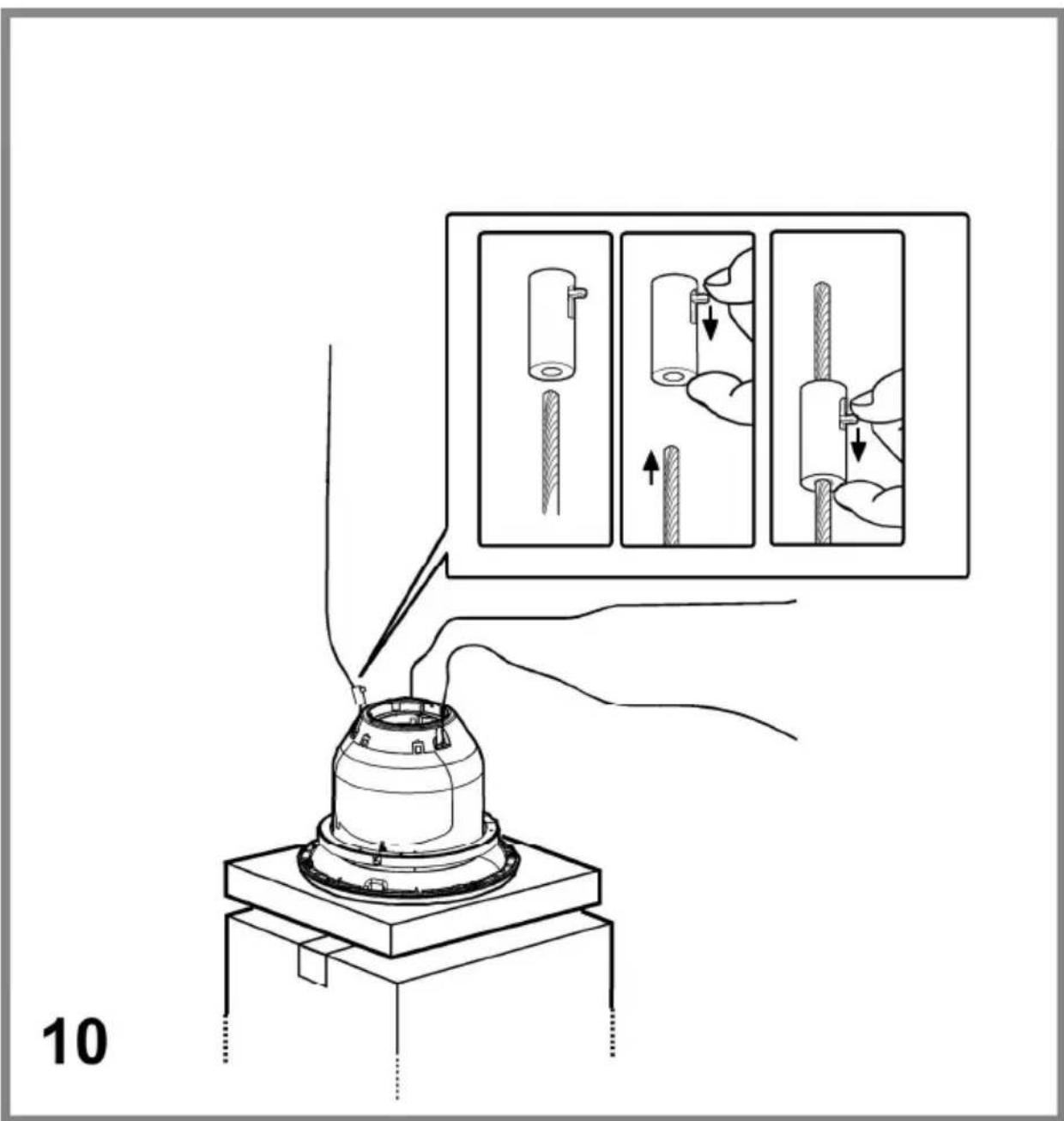


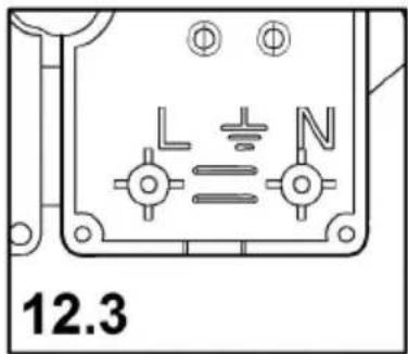


15


20
21
22


23a


23b



24a


25a
25b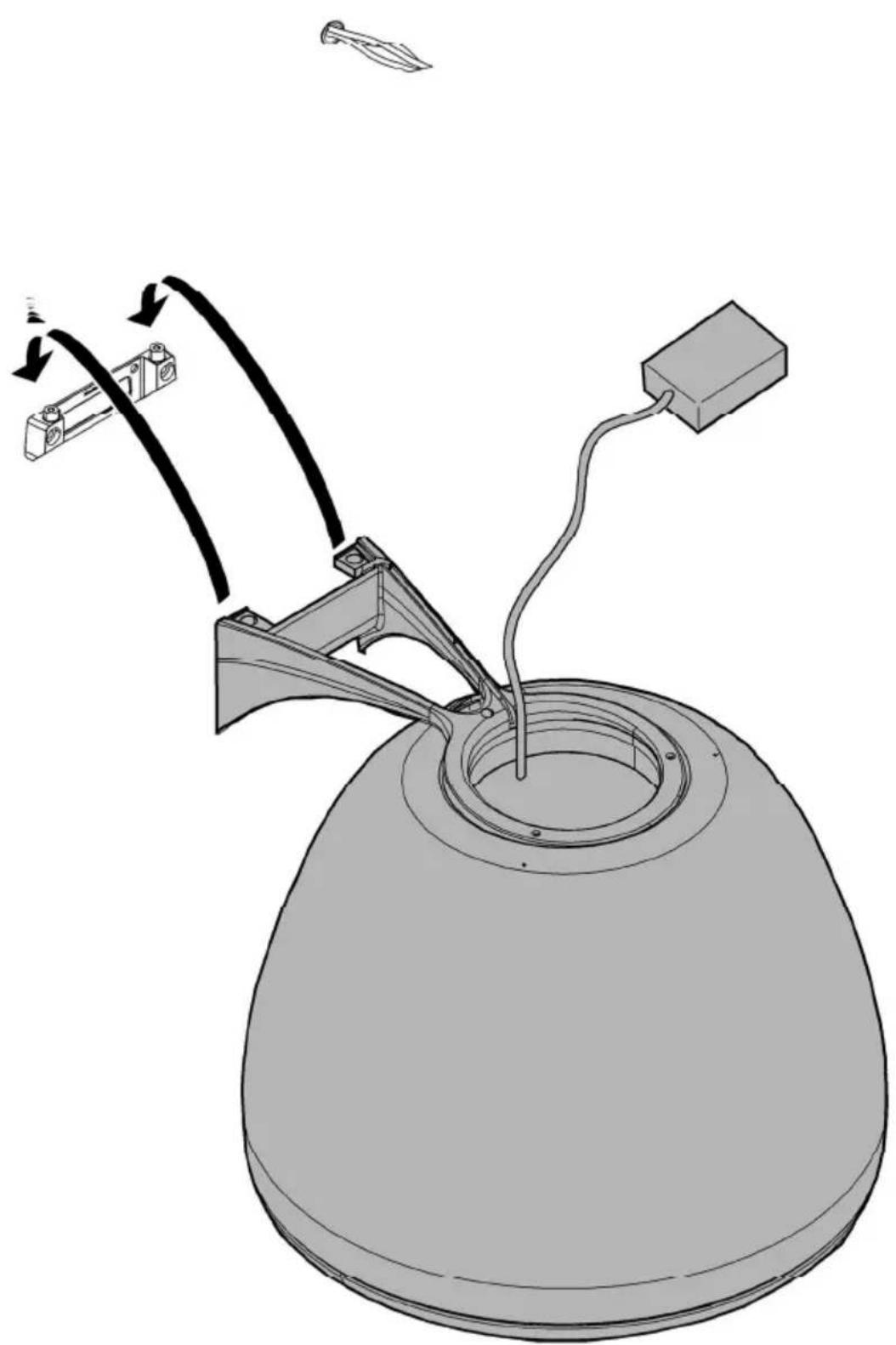


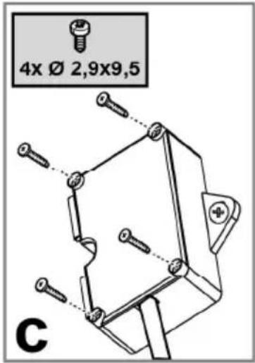
26a.1
26a.3

26a


26b


28


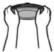


29

30.1

30.2

30
EN - Instruction on mounting and use
Closely follow the instructions set out in this manual. All responsibility, for any eventual inconveniences, damages or fires caused by not complying with the instructions in this manual, is declined. This appliance is intended to be used in household and similar applications such as: - staff kitchen areas in shops, offices and other working environments; - farm houses; - by clients in hotels, motels and other residential type environments; - bed and breakfast type environments.
! It is important to conserve this booklet for consultation at any moment. In the case of sale, cession or move, make sure it is together with the product. ! Read the instructions carefully: there is important information about installation, use and safety. ! Do not carry out electrical or mechanical variations on the product or on the discharge conduits. ! Before proceeding with the installation of the appliance verify that there are no damaged all components. Otherwise contact your dealer and do not proceed with the installation.
Note: the elements marked with the symbol “(*)” are optional accessories supplied only with some models or elements to purchase, not supplied.
The hood can look different to that illustrated in the drawings in this booklet. The instructions for use, maintenance and installation, however, remain the same.

Caution
Before any cleaning or maintenance operation, disconnect hood from the mains by removing the plug or disconnecting the mains electrical supply. Always wear work gloves for all installation and maintenance operations.
This appliance can be used by children aged from 8 years and above and persons with reduced physical, sensory or mental capabilities or lack of experience and knowledge if they have been given supervision or instruction concerning use of the appliance in a safe way and understand the hazards involved.
Children shall not be allowed to tamper with the controls or play with the appliance.
Cleaning and user maintenance shall not be made by children without supervision.
The premises where the appliance is installed must be sufficiently ventilated, when the kitchen hood is used together with other gas combustion devices or other fuels.
The hood must be regularly cleaned on both the inside and outside (AT LEAST ONCE A MONTH).
This must be completed in accordance with the maintenance instructions provided. Failure to follow the instructions provided regarding the cleaning of the hood and filters will lead to the risk of fires.
Do not flambé under the range hood.
The use of exposed flames is detrimental to the filters and may cause a fire risk, and must therefore be avoided in all circumstances.
Any frying must be done with care in order to make sure that the oil does not overheat and ignite.
CAUTION: Accessible parts of the hood may become hot when used with cooking appliances.
For lamp replacement use only lamp type indicated in the Maintenance/Replacing lamps section of this manual.
WARNING! Do not connect the appliance to the mains until the installation is fully complete.
With regards to the technical and safety measures to be adopted for fume discharging it is important to closely follow the regulations provided by the local authorities.
The air must not be discharged into a flue that is used for exhausting fumes from appliance burning gas or other fuels.
Do not use or leave the hood without the lamp correctly mounted due to the possible risk of electric shocks.
Never use the hood without effectively mounted grids.
The hood must NEVER be used as a support surface unless specifically indicated.
Use only the fixing screws supplied with the product for installation or, if not supplied, purchase the correct screws type.
Use the correct length for the screws which are identified in the Installation Guide.
In case of doubt, consult an authorised service assistance centre or similar qualified person.
WARNING! Failure to install the screws or fixing device in accordance with these instructions may result in electrical
hazards.
Do not use with a programmer, timer, separate remote control system or any other device that switches on automatically.
Note: any imperfections in cosmetic appearance are to be considered as particular characteristics of the product itself.
This appliance is marked according to the European directive 2012/19/EC on Waste Electrical and Electronic Equipment (WEEE). By ensuring this product is disposed of correctly, you will help prevent potential negative consequences for the environment and human health, which could otherwise be caused by inappropriate waste handling of this product.

The symbol ■ on the product, or on the documents accompanying the product, indicates that this appliance may not be treated as household waste. Instead it should be taken to the appropriate collection point for the recycling of electrical and electronic equipment. Disposal must be carried out in accordance with local environmental regulations for waste disposal.
For further detailed information regarding the process, collection and recycling of this product, please contact the appropriate department of your local authorities or the local department for household waste or the shop where you purchased this product.
Appliance designed, tested and manufactured according to:
- Safety: EN/IEC 60335-1; EN/IEC 60335-2-31, EN/IEC 62233.
• Performance: EN/IEC 61591; ISO 5167-1; ISO 5167-3; ISO 5168; EN/IEC 60704-1; EN/IEC 60704-2-13; EN/IEC 60704-3; ISO 3741; EN 50564; IEC 62301.
- EMC: EN 55014-1; CISPR 14-1; EN 55014-2; CISPR 14-2; EN/IEC 61000-3-2; EN/IEC 61000-3-3. Suggestions for a correct use in order to reduce the environmental impact: Switch ON the hood at minimum speed when you start cooking and keep it running for a few minutes after cooking is finished. Increase the speed only in case of large amount of smoke and vapour and use boost speed(s) only in extreme situations. Replace the charcoal filter(s) when necessary to maintain a good odour reduction efficiency. Clean the grease filter(s) when necessary to maintain a good grease filter efficiency. Use the maximum diameter of the ducting system indicated in this manual to optimize efficiency and minimize noise.
Use
The hood has been made for use in the internal recirculating filtering version.
Cooking fumes and steam are aspirated inside the hood, filtered and cleaned, passing through the fat filter/s and the carbon filter/s that MUST be supplied with the hood.
Important
It is possible to buy an extraction operation Kit.
In this case the charcoal filter must not be installed.
Furthermore, the use of the extraction kit may require a different installation of the hood from what is shown in this manual; therefore, before starting the installation of the hood, buy the extraction kit and consult the instructions enclosed with the kit.
Installation
Specialised personnel must carry out both the electrical and the mechanical installation.
The minimum distance between the supporting surface for the cooking equipment on the hob and the lowest part of the range hood must be not less than 50cm from electric cookers and 65cm from gas or mixed cookers.
If the instructions for installation for the gas hob specify a greater distance, this must be adhered to.

Electrical connection
The mains tension must correspond to the tension shown on the characteristic label situated inside the hood.
The product is meant for connecting directly to the mains supply, therefore apply a regulation bipolar switch that ensures complete disconnection from the mains in the conditions of category III over-tension, conforming to the installation rules.
Warning! Detail B (fixing bracket to the ceiling) is equipped with a conductor (yellow-green) that must be connected to the earth of the domestic electrical plant. Fig. 16-17

ATTENTION! Be particularly careful about positioning excess cable. Failure to observe this indication could cause grave damage to the apparatus and/or an electric shock to the user or the installer.
Warning! Changing the interconnection cable must be carried out by the authorised technical assistance service.
Mounting
Before beginning installation:
- Check that the product purchased is of a suitable size for the chosen installation area.
- Remove the charcoal (*) filter/s if supplied (see also relative paragraph). This/these is/are to be mounted only if you want to use the hood in the filtering version.
- Check (for transport reasons) that there is no other supplied material inside the hood (e.g. packets with screws (*), guarantees (*), etc.), eventually removing them and keeping them.
This type of cooker hood must be fixed to the ceiling.
Very heavy product; hood handling and installation must be carried out by at least two persons.
Expansion wall plugs are provided to secure the hood to most types of walls/ceilings. However, a qualified technician must verify suitability of the materials in accordance with the type of wall/ceiling. The wall/ceiling must be strong enough to take the weight of the hood. Do not tile, grout or silicone this appliance to the wall. Surface mounting only.
Operation
The hood has an on-board controller which can also be used with the specific remote control (only supplied on some models) Control panel on hood

T1. Suction speed (power) control key.
Press repeatedly until the desired speed is selected, choosing between:
Speed OFF – LED L1: off
Speed 1 (low suction) – LED L1: green light
LED L2 turns green and flashes if the delayed hood deactivation is enabled (only with remote control).
Speed 2 (medium suction) – LED L1: yellow light
LED L2 turns yellow and flashes if the delayed hood deactivation is enabled (only with remote control).
Speed 3 (high suction) – LED L1: blue light
LED L2 turns blue and flashes if the delayed hood deactivation is enabled (only with remote control).
Speed 4 (intensive suction) – LED L1: Blue button
Note 1: Speed 4 has a limited duration of 5 min., and then the hood passes automatically to speed 2.
T2. Light control key (hob light-dim light)
Press briefly to light up the hob
Keep it pressed longer to light up the dim light
Note: The dim light is only available on some models.
Grease filter saturation warning - LED L1: red light
The warning is visible for about one minute after switching the hood off. When this warning appears the grease filter requires maintenance.
Charcoal filter saturation warning - LED L1: red light
The warning is available for about one minute after switching the hood off.
When this warning appears the charcoal filter requires maintenance.
Deactivation/activation of charcoal filter saturation warning:
This warning is normally activated, to deactivate it:
with hood off, press keys T1 and T2 simultaneously until you hear a beep.
Release both keys and press the same keys again, T1 and T2, shortly.
LED L1 lights up steady with a red light (warning on) and then starts to flash (warning off).
Repeat the operation if you want to reactivate the warning. LED L1 switches from flashing red (warning off) to a steady light (warning on).
Filter saturation warning reset
With the hood off, press keys T1 and T2 simultaneously for at least 5 seconds. LED L1 will stop signalling saturation.
Repeat the operation in case of simultaneous warnings of both filters.
Remote control affiliation
The affiliation of the remote control is displayed with both LEDs on, which show several colours in sequence.
Automatic operation (sensor), connection with SNAP®
Warning! It is recommended to perform the 'Adjusting the parameters for automatic operation' (see relevant paragraph) before using the automatic mode and connect the hood to the SNAP®.
Automatic operation (sensor)
The hood will switch on at an adequate speed depending on the cooking fumes detected by the hood sensor.
To activate this function:
Press keys T1 and T2 simultaneously. LED L1 will light up showing several colours, whereas LED L2 will turn white.
Automatic operation of the hood with SNAP®
Note: SNAP® is an auxiliary suction unit capable of operating together with the hood. For further information, refer to the manual supplied with SNAP®
To activate this function:
Press keys T1 and T2 simultaneously. LED L1 will light up showing several colours, whereas LED L2 will turn orange.
Adjusting the parameters for automatic operation.
Note: All the calibration, selection, adjustment, and logical connection operations described below are possible with hood OFF and involve:
- Hood calibration (automatic or manual).
• Hob selection (gas - induction or electrical)
- Logical connection between hood and SNAP (if in possession of SNAP ).
Sensor calibration
Note: Calibration lasts about 5 minutes. LEDs L1 and L2 turn white and flash.
Calibration is required to allow the hood sensor to run properly. Calibration can be:
Automatic:
every time the hood is reconnected to the mains (e.g. upon first installation or after a blackout).
Manual:
To be carried out if unsatisfactory automatic operation is detected and under normal kitchen conditions.
Press and hold key T1..
Hob selection (gas - induction or electrical)
Simultaneously press keys T1 and T2 until you hear a beep. Release the keys and press solely T2 (within about 5 seconds) to access the hob selection mode.
Press T2 again to choose the required hob according to the layout below:
Orange LED 2: Gas hob
Blue LED 2: Induction hob
White LED 2: Electrical hob
The selected key remains on to indicate the selection. After 10 seconds, the key flashes temporarily to indicate that the selection made has been recorded.
Logical connection between hood and SNAP ® (if in the possession of SNAP ®).
The connection between hood and SNAP ® is automatic. No setting is required.
Remote control
Warning! Some functions of this remote control may only be activated with certain hood models.

Remote control affiliation:
Keep T2 + T5 pressed within the first minute the hood is powered. Once pairing is complete it is displayed on the hood.
Description of the remote control functions
T1. OFF key T2. ON/OFF key and dim light intensity adjustment T3. Suction speed (power) control key: T4. Hob light ON/OFF key T5. Delayed hood ON/OFF key T6. Sensor ON/OFF key. T7. Filter saturation warning reset key. L3. Remote control operation LED
Note: touch the keys lightly to select the available functions.
T1. OFF key: Press to switch the hood off. T2. ON/OFF key and dim light intensity adjustment: Press briefly to switch the dim light on or off. Press longer to adjust intensity. Note: The dim light is only available on some models.
T3. Suction speed (power) control key: Touch the key starting from any position, turning it clockwise or anticlockwise to increase or decrease suction speed. The key is divided into several sectors. You can select the desired speed directly in the corresponding sector as follows:
T3a: Speed 1 (low suction)
T3b: Speed 2 (medium suction)
T3c: Speed 3 (high suction)
T3d: Speed 4 (intensive suction)
T4. Hob light ON/OFF key: Press to switch the hob light on or off.
T5. Delayed hood ON/OFF key: Press to program the delayed switch-off of the hood based on the suction speed (power) active at that moment:
Speed 1 (low suction): 20 minutes
Speed 2 (medium suction): 15 minutes
Speed 3 (high suction): 10 minutes
T6. Sensor ON/OFF key: Keep it pressed to activate/deactivate the mode with sensor which manages fume extraction in automatic mode.
Note: The sensor is only available in some models.
T7. Filter saturation warning reset key.
Maintenance of the remote control
Cleaning the remote control:
Clean the remote control with a damp cloth and a neutral detergent solution, without abrasive substances.
Changing the battery:
- Open the battery compartment.
- Replace the flat batteries with 3 new 1.5 V type AAA batteries.
Respect the polarity indicated in the battery compartment when inserting the new batteries!
Close the battery compartment again.

Disposal of the batteries
Ultimate disposal of the batteries should be handled according to all national laws and regulations. Do not place used batteries in your regular waste.
Ultimate disposal of the batteries must be done safely.
Contact your local waste management officials for other information regarding the environmentally sound collection, recycling, and disposal of the batteries.
Maintenance
Cleaning
Clean using ONLY the cloth dampened with neutral liquid detergent. DO NOT CLEAN WITH TOOLS OR INSTRUMENTS. Do not use abrasive products. DO NOT USE ALCOHOL!
Grease filter
Fig. 28-29-30
Traps cooking grease particles.
This must be cleaned at least once a month (or when the filter saturation indication system - if present on the model in your possession - indicates this necessity), using non-aggressive detergents, in a dishwasher, which must be set to a low
temperature and a short cycle (Tmax: 70°C).
When washed in a dishwasher, metal parts may discolour slightly.
The filter must be dried in an oven for one hour at a max temperature of 100°C; if the filter is still moist, repeat the operation.
Replace the filter at least every 2 years.
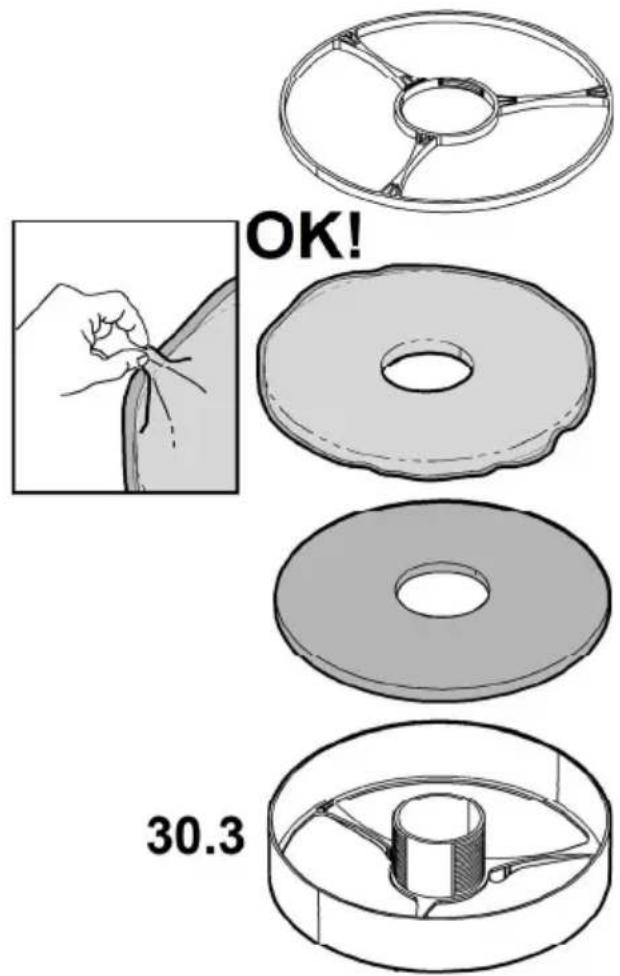
Attention! After having performed maintenance on the filter, FIRST install the grease filter in the specific container and THEN the charcoal filter. The latter can be recognised as it is sealed inside a braiding.
Once the container has been repositioned, make sure only the grease filter is visible.
Charcoal filter (filter version only)
Fig. 28-29-30
It absorbs unpleasant odours caused by cooking.
Attention! The active charcoal filter can be recognised as it is sealed inside a braiding. Perform disassembly, maintenance and cleaning operations of the filter, managing it with the utmost care to avoid damaging or opening the braiding.
The charcoal filter can be washed once every two months (or when the filter saturation indication system – if present on the model in your possession – indicates this necessity) using hot water and a suitable detergent, or in a dishwasher at 65°C (if the dishwasher is used, select the full cycle function and leave dishes out).
Eliminate excess water without damaging the filter, then put it in the oven for 10 minutes at 100°C to dry completely. Replace the mattress every 3 years and when the cloth is damaged.
Attention! After having performed maintenance on the filter, FIRST install the grease filter in the specific container and THEN the charcoal filter. The latter can be recognised as it is sealed inside a braiding.
Once the container has been repositioned, make sure only the grease filter is visible.
Replacing lamps
Fig. 29
The hood is equipped with a lighting system based on LED technology.
The LEDs guarantee an optimum lighting, a duration up to 10 times as long as the traditional lamps and allow to save 90% electrical energy.
To purchase spare LEDs, contact the technical assistance service.
Speed 4 (intensive aspiration) – LED L1: sky blue button
T3d: Speed 4 (intensive aspiration)
Electrical and Electronic Equipment (WEEE)
- EN - INSTRUCTION ON MOUNTING AND USE
- CAUTION
- USE
- IMPORTANT
- INSTALLATION
- ELECTRICAL CONNECTION
- MOUNTING
- BEFORE BEGINNING INSTALLATION
- OPERATION
- GREASE FILTER SATURATION WARNING - LED L1: RED LIGHT
- CHARCOAL FILTER SATURATION WARNING - LED L1: RED LIGHT
- FILTER SATURATION WARNING RESET
- REMOTE CONTROL AFFILIATION
- AUTOMATIC OPERATION (SENSOR), CONNECTION WITH SNAP®
- AUTOMATIC OPERATION (SENSOR)
- AUTOMATIC OPERATION OF THE HOOD WITH SNAP®
- ADJUSTING THE PARAMETERS FOR AUTOMATIC OPERATION
- SENSOR CALIBRATION
- AUTOMATIC
- MANUAL
- REMOTE CONTROL
- DESCRIPTION OF THE REMOTE CONTROL FUNCTIONS
- MAINTENANCE OF THE REMOTE CONTROL
- CLEANING THE REMOTE CONTROL
- CHANGING THE BATTERY
- DISPOSAL OF THE BATTERIES
- MAINTENANCE
- CLEANING
- GREASE FILTER
- FIG
- TRAPS COOKING GREASE PARTICLES
- CHARCOAL FILTER (FILTER VERSION ONLY)
- IT ABSORBS UNPLEASANT ODOURS CAUSED BY COOKING
- REPLACING LAMPS
Brand : ELICA
Model : PRF0120497
Category : Range hood