
VTI-4085-V511 - Surveillance Camera BOSCH - Free user manual and instructions
Find the device manual for free VTI-4085-V511 BOSCH in PDF.


| Product Type | Surveillance Camera |
| Brand | Bosch |
| Model | VTI-4085-V511 |
| Dimensions (H x W x D) | Approx. 10 x 6 x 6 cm |
| Weight | Approx. 150 g |
| Power Supply | 12V DC via included adapter |
| Power Consumption | 5 W typical |
| Video Resolution | 1080p Full HD |
| Field of View | 90° wide angle |
| Night Vision | Infrared up to 10 m |
| Connectivity | Ethernet (RJ-45) |
| Storage | MicroSD card up to 128 GB |
| Weatherproof Rating | IP67 (indoor/outdoor) |
| Mounting | Wall or ceiling mount included |
| Operating Temperature | -20°C to 50°C |
| Maintenance | Clean lens with soft dry cloth |
| Safety Features | Tamper alarm, encryption |
| Spare Parts | Mounting kit, power adapter (order via Bosch service) |
| Repairability | User-replaceable lens and cable |
| Warranty | 2 years |
| Manual Language | English |
Frequently Asked Questions - VTI-4085-V511 BOSCH
User questions about VTI-4085-V511 BOSCH
0 question about this device. Answer the ones you know or ask your own.
Ask a new question about this device
Download the instructions for your Surveillance Camera in PDF format for free! Find your manual VTI-4085-V511 - BOSCH and take your electronic device back in hand. On this page are published all the documents necessary for the use of your device. VTI-4085-V511 by BOSCH.
USER MANUAL VTI-4085-V511 BOSCH
natural_image
BOSCH security camera with visible lens and port, no text or symbols on bodyAN bullet 4000 IR
960H Day/Night IR Bullet Camera

BOSCH
en User Manual
简体中文版 使用手册
Table of Contents
1 Cautions
2 Important safety instruction
3 Features
4 Components
5 Camera parts
6 Installation
6.1 Mounting position
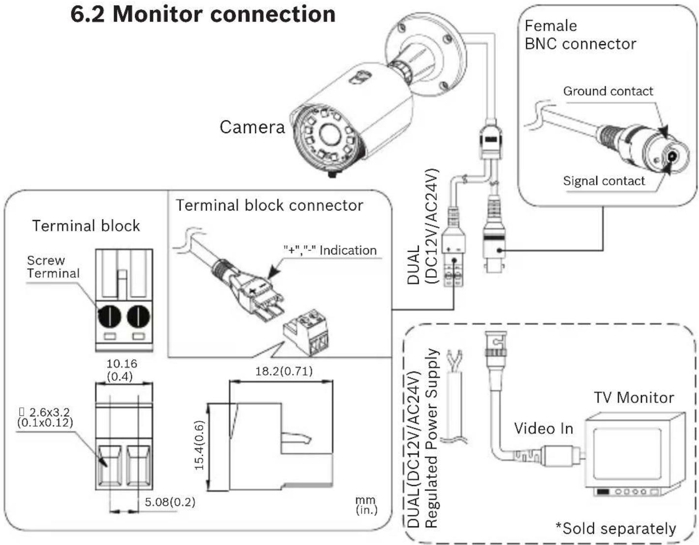
6.2 Monitor connection
6.3 Camera adjustment
7 OSD menu structure
8 Specification
8.1 Dimensions
1 Cautions
This device complies with Part 15 of the FCC Rules. Operation is subject to the following two conditions;
- This device may not cause harmful interference.
- This device must accept any interference received, including interference that may cause undesired operation.

Note!
This equipment has been tested and found to comply with the limits for a Class A digital device, pursuant to part 15 of the FCC Rules. These limits are designed to provide reasonable protection against harmful interference when the equipment is operated in a commercial environment. This equipment generates, uses, and can radiate radio frequency energy and, if not installed and used in accordance with the instruction manual, may cause harmful interference to radio communications. Operation of this equipment in a residential area is likely to cause harmful interference in which case the user will be required to correct the interference at his own expense.”

WARNING
This is a class A product. In a domestic environment this product may cause radio interference in which case the user may be required to take adequate measures.

CAUTION!
Any changes or modifications in construction of this devies which are not expressly approved by the party responsible for compliance could void the user's authority to operate the equipment.

CAUTION!
- A regulated DC12V 500mA power supply is recommended for use with this camera for the best picture and the most stable operation.
An unregulated power supply can cause damage to the camera.
When unregulated power supply is applied, product warranty will be out of subject. - It is recommended that the camera is used with a monitor that has a CCTV quality 75 video impedance level. If your monitor is switched to high impedance then please adjust accordingly.
- Do not attempt to disassemble the camera to gain access to the internal components. Refer servicing to your dealer.
- Never face the camera towards the sun or any bright or reflective light, which may cause smear on the picture and possible damage to the CCD.
- Do not remove the serial sticker for the warranty service.
- Do not expose the camera to rain or other types of liquid.
- The apparatus must be connected to a mains socket-outlet with a protective earthing connection.

Correct Disposal of This Product (Waste Electrical & Electronic Equipment)
(Applicable in the European Union and other European countries with separate collection systems)
This marking shown on the product or its literature, indicate that it should not be disposed with other household wastes at the end of its working life. To prevent possible harm to the environment or human health from uncontrolled waste disposal, please separate this from other types of wastes and recycle it responsibly to promote the sustainable reuse of material resources.
This product should not be mixed with other commercial wastes purchased this product, or their local government office, for details of where and how they can take item for environmentally safe recycling. Business users should contact their supplier and check the terms and conditions of the purchase contract.
Household users should contact either the retailer where they for disposal.

CAUTION:
CAUTION
RISK OF ELECTRIC SHOCK DO NOT OPEN

TO REDUCE THE RISK OF ELECTRIC SHOCK, DO NOT REMOVE COVER(OR BACK). NO USER. SERVICING TO QUALIFIED SERVICE PERSONNEL.

This symbol is intended to alert the user to the presence of uninsulated “dangerous voltage” within the product’s enclosure that may be of sufficient magnitude to constitute a risk of electric shock to persons.
This symbol is intended to alert the user to the presence of important operating and maintenance(servicing) instruction in the literature accompanying the appliance.

CAUTION!
These servicing instructions are for use by qualified service personnel only. To reduce the risk of electric shock do not perform any servicing other than that contained in the operating instructions unless you are qualified to do so.
Use Class 2 Power Supply Only
2 Important safety instructions
- Read these instructions.
- Keep these instructions.
- Heed all warnings.
- Follow all instructions.
- Do not use this apparatus near water.
-
Clean only with dry cloth.
-
Do not block any ventilation openings. Install in accordance with the manufacturer's instructions.
-
Do not install near any heat sources such as radiators, heat registers, stoves, or other apparatus (including amplifiers) that produce heat.
-
Do not defeat the safety purpose of the polarized or grounding-type plug. A polarized plug has two blades with one wider than the other. A grounding type plug has two blades and a third grounding prong. The wide blade or the third prong are provided for your safety. If the provided plug does not fit into your outlet, consult an electrician for replacement of the obsolete outlet.
-
Protect the power cord from being walked on or pinched particularly at plugs, convenience receptacles, and the point where they exit from the apparatus.
-
Only use attachments/accessories specified by the manufacturer.
-
Use only with the cart, stand, tripod, bracket, or table specified by the manufacturer, or sold with the apparatus. When a cart is used, use caution when moving the cart/apparatus combination to avoid injury from tip-over.

-
Unplug this apparatus during lightning storms or when unused for long periods of time.
-
Refer all servicing to qualified service personnel. Servicing is required when the apparatus has been damaged in any way, such as power-supply cord or plug is damaged, liquid has been spilled or objects have fallen into the apparatus, the apparatus has been exposed to rain or moisture, does not operate normally, or has been dropped.
3 Features
The camera has the following features:
• Ultra high resolution, 960H (1/3") Sensor.
- 5-50mm lens with True Day/Night filter for optimum performance in various lighting conditions.
• 720 TV Lines Horizontal Sensor Resolution.
• Integrated IR LED's for discrete surveillance in dark environments.
- Optimized IR beam pattern for a more even illumination throughout the camera's field of view.
• Multi language On Screen Display (OSD) with joystick control.
• True Wide Dynamic Range. (WDR)
3DNR
• 15 Privacy Zones.
- Motion Detection.
• External lens adjustment.
- Cable managed bracket for secure and clean installation.
• Vandal resistant (IK08)
• Outdoor rated (IP66)
4 Components
| Qty Description | |||
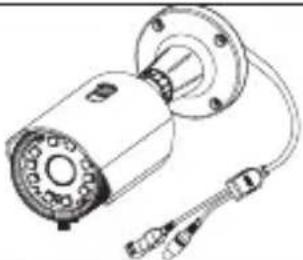 | 1 | VTI-4085-V5x1(C)camera with integratedmounting bracket | |
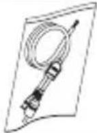 | 1 | Video OutputTest Cable | |
 | 4 | Screws(PH/1(SUS) 5x30) | |
 | 1 | Wrench(M6 hex) | |
 | 1 Guide Pattern | ||
 | 1 | User Manual(this booklet) | |
5 Camera parts

1 Sunshield Fixing Bolt
2 Sunshield
3 Housing Front
4 Housing Body
5 Housing Back
6 Mounting Bracket
7 Photo cell
8 Lens Knob
9 LED
10 Lens

6 Installation
6.1 Mounting position
To prevent injury, this apparatus must be securely attached to the floor/wall in accordance with the installation instructions.
NOTICE! The image sensors in modern cameras are highly sensitive and require special care for proper performance and extended lifetime. Follow the guidelines for optimum results with your camera:
- Do not expose to direct sunlight or bright spotlights in operating and nonoperating conditions.
- Avoid bright lights in the field of view of the camera. Bright lights cause a “smearing” effect, which is visible as white lines above and below the highlight. Prolonged exposure to bright lights may cause bleaching of the sensor's color filters. This will be visible as colored spots in the picture and is irreversible.
WARNING! The mounting surface, mounting screws/plugs, and junction box must be stable and capable of supporting a maximum load of 10kg (22 pounds). Mounting to an improper surface or using improper mounting material can cause camera malfunction and is a potential safety hazard.
WARNING! Make sure that appropriate mounting screws and anchors are used for the surface to which the camera is mounted. The supplied universal mounting screws can be used with most plastic anchors, please confirm compatibility before mounting the camera.
CAUTION! To prevent humidity problems, the camera must be installed in dry conditions, and the cable leads should be sealed after they are connected.

6 Installation
6.3 Camera adjustment
CAUTION! To prevent humidity problems, the camera must be installed in dry conditions. The lens knobs (located on the bottom of the camera) and protection cap (located on the rear of the camera) provide protection against water ingress when fully tightened. Therefore never remove or keep them loosened after installation. Doing so could cause water ingress and/or condensation on the inside of the camera window.
- Open the protection cap on the rear of the camera (only needed to access service monitor connection and OSD control)
- Connect service monitor (optional)
- Loosen the zoom and focus knob
- Adjust zoom and focus
- Fasten the zoom and focus knob tightly
- Adjust OSD settings (refer to OSD section)
- Disconnect service monitor cable (optional)
- Check rubber seal is in place on the protection cap. Close and firmly tighten the protection cap on the rear of the camera.
7 OSD menu structure
| MAIN MENU | 1st Sub 2nd Sub 3rd Sub 4th | Sub | ||
| EXPOSURE | AUTO | HIGH LUMINANCE | FLICKERLESS OFF,ON | |
| BRIGHTNESS 00 ~ 255 | ||||
| LOW LUMINANCE | MODE | OFF, AGC, SLOW, AGC->SLOW, AGC->SLOW->AGC | ||
| AGC MAX 6, 12 | 18, 24, 30, 36 | |||
| DSS MAX | 2, 48, 16, 32, 64, 128, 256 | |||
| BRIGHTNESS | x0.25, x0.50, x0.75, x1.00 | |||
| RETURN | ||||
| MANUAL | MODE | SHUTTER, SLOW | ||
| SHUTTER | 1/50(PAL), 1/120(PAL) 1/60(NTSC), 1/100(NTSC) 1/250,1/500, 1/1000,1/2000 1/4000,1/10000, 1/100000 | |||
| AGC | 6, 12, 18, 24, 30, 36, 42, 44. 8 | |||
| RETURN | ||||
| MAIN MENU | 1st Sub 2nd S | Sub 3rd Sub 4th $ub | ||
| WHITE BAL | ATW | SPEED | 000 ~ 255 | |
| DELAY CNT | 000 ~ 255 | |||
| ATW FRAME | x0.50, x1.00, x1.50, x2.00 | |||
| ENVIRONMENT | INDOOR, OUTDOOR | |||
| RETURN | ||||
| PUSH | ||||
| USER1 | B-GAIN | 000 ~ 255 | ||
| R-GAIN | 000 ~ 255 | |||
| RETURN | ||||
| USER2 | B-GAIN | 000 ~ 255 | ||
| R-GAIN | 000 ~ 255 | |||
| RETURN | ||||
| MANUAL | LEVEL | 000 ~ 128 | ||
| RETURN | ||||
| PUSH LOCK | ||||
7 OSD menu structure
| MAIN MENU | 1st Sub 2nd Sub | 3rd Sub 4th Sub | ||
| DAY&NIGHT | AUTO | DELAY CNT 000 | ~ 015 | |
| DAY -> NIGHT 000 ~ 014 | ||||
| NIGHT -> DAY 000 ~ 015 | ||||
| BURST ON, OFF | ||||
| IR OPTIMIZER ON, OFF | ||||
| RETURN ON, OFF, AUTO | ||||
| BW | BURST ON, OFF | |||
| IR OPTIMIZER ON, OFF | ||||
| IR LED MODE | ||||
| RETURN | ||||
| COLOR | ||||
| WDR/BLC | WDR MODE | ON | LEVEL 000 ~ 015 | |
| CONTRAST1 000 | ~ 007 | |||
| CONTRAST2 000 | ~ 004 | |||
| OFF | ||||
| BLC MODE | ON | BLC ZONE | TOP, LEFT, RIGHT, BOTTOM, CENTER | |
| LEVEL 000 ~ 015 | ||||
| OFF | ||||
| HLC MODE | ON. AUTO | CLIP LEVEL | 000 ~ 255 | |
| SCALE | 000 ~ 015 | |||
| OFF |
| DNR | 2DNR MODE | ON, OFF | ||
| 2DNR LEVEL | 000 ~ 015 | |||
| 3DNR MODE | ON, OFF | |||
| 3DNR LEVEL | 000 ~ 063 | |||
| RETURN |
| IMAGE | FLIP | OFF, V-FLIPH-FLIP, HV-FLIP | ||
| FREEZE ON, OFF | ||||
| EZOOM 1x ~ 3x | ||||
| CONTRAST | 000 ~ 063 | |||
| SHARPNESS | 000 ~ 015 | |||
| RETURN | ||||
7 OSD menu structure
| MAIN MENU | 1st Sub 2nd | Sub 3rd Sub 4th | Sub | |
| SPECIAL | CAMERA TITLE | ON | EDIT MODE | |
| RETURN | ||||
| OFF | ||||
| LANGUAGE | ENGLISH中文Русский ESPAÑOL DEUTSCH FRANCAISE PORTUGUÊS日本語 | |||
| PRIVACY | AREA SEL 1 ~ 15 | |||
| MODE ON, OFF | ||||
| POSITION POSITION | ON EDIT | |||
| COLOR | WHITE, BLACK, RED, GREEN, BLUE, YELLOW, CYAN, MAGENTA | |||
| TRANSPARENCY | 0.00, 0.05, 0.75, 1.00 | |||
| MOSAIC ON, OFF | ||||
| RETURN | ||||
| MOTION DETECT | ON | DETECT SENSE 000 ~ 127 | ||
| BLOCK DISP ON, OFF | ||||
| MONITOR AREA | AREA SEL: 1 ~ 4 | |||
| MODE: ON. OFF | ||||
| TOP: 000 ~ 015 | ||||
| BOTTOM: 000 ~ 015 | ||||
| LEFT: 000 ~ 023 | ||||
| RIGHT: 000 ~ 023 | ||||
| RETURN | ||||
| RETURN | ||||
| OFF | ||||
| RETURN | ||||
| FACTORY DEFAULT | ||||
| EXIT | ||||
| SAVE & EXIT | ||||
* Important Note:
- Any changes made to the camera settings must be saved prior to exiting the OSD menu. Otherwise all changes will be discarded.
8 Specification
| Model | VTI-4085-V521(NTSC) VTI-4085-V511(PAL) | |
| Image Device | Ultra high resolution, 960H (1/3") Sensor | |
| Scanning System | 2 : 1 Interlace | |
| Scanning Frequency | 15.734 KHz(H),59.94 Hz(V) | 15.625 KHz(H), 50 Hz(V) |
| H. Sensor Res. | 720TVL | |
| Actual H. Res. | 620TVL | |
| Total Pixels | 1028(H) x 508(V) 1028(H) x 596(V) | |
| Effective Pixels | 976(H) x 494(V) 976(H) x 582(V) | |
| S/N Ratio | More than 50dB (AGC Off, 3DNR on) | |
| Min. Illumination | 0 Lux (IR LED On) | |
| Sync. System | Internal | |
| Gamma | r = 0.45 | |
| Video Output | 1.0 Vp-p Composite (75Ω) | |
| Lens | Varifocal Auto IRIS & DN Lens Built-in | |
| Lens focal length | 5-50mm | |
| Aperture | F1.4~360 | |
| Lens adjustment | External | |
| Electronic Shutter | 1/60 sec 1/50 sec | |
| WDR | Yes | |
| BLC | OFF / BLC / HLC / WDR | |
| White Balance | ATW / PUSH / USER1 / USER2 / MANUAL / PUSH-LOCK | |
| 2DNR / 3DNR | On / Off (Level Adjustable) | |
| Function | MIRROR / FREEZE / FLIP / CONTRAST / SHARPNESS / DSS | |
| Motion Detection | Zone 4ea | |
| Privacy Masking | Zone 15ea | |
| Language | English, Simplified Chinese, German, French, Russian, Portuguese, Spanish, Japanese | |
| Day & Night | True Day & Night with ICR Mechanism | |
| OSD | Built-in | |
| OSD Control | External | |
| IR LED [m(ft)] 850 nm | max 100m (330ft) | |
| IR Angle H/V 39/24 degrees | ||
| IP Rating | IP66 (Water resistant) | |
| Operating Temperature | -30 °C to +50 °C (-22 °F to +122 °F) | |
| Storage Temperature | -20°C to +60°C (-4°F to +140°F) | |
| Power Consumption | Dual : DC12V(±10%), Max. 730 mA / AC24V(±10%), Max. 9.1 W | |
| Cable Management Bracket | Yes | |
| Video interface | 1 standard BNC connector for analog output | |
| Weight | Approx. 1.9kg(including bracket) | |
| Housing material Casted/machined Aluminium | ||
| Paint color Camera / bracket: Black RAL9017Sunshield: Silver grey RAL9006 | ||
| Vandal resistant | Yes (IK08) | |
| Outdoor rated | Yes (IP66) | |
8-1 Dimensions

mm
(in.)
目录
Bosch Security Systems
www.boschsecurity.com
(c) Bosch Security Systems, 2013


- AN bullet 4000 IR
- 960H Day/Night IR Bullet Camera
- BOSCH
- Table of Contents
- Cautions
- This device complies with Part 15 of the FCC Rules. Operation is subject to the following two conditions;
- Note!
- WARNING
- CAUTION!
- Correct Disposal of This Product (Waste Electrical & Electronic Equipment)
- CAUTION
- RISK OF ELECTRIC SHOCK DO NOT OPEN
- Important safety instructions
- Features
- Components
- Camera parts
- Installation
- Mounting position
- Camera adjustment
- 目录
- Bosch Security Systems
- www.boschsecurity.com
Brand : BOSCH
Model : VTI-4085-V511
Category : Surveillance Camera