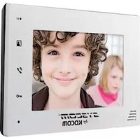
KCVD372W - Intercom Syscom - Free user manual and instructions
Find the device manual for free KCVD372W Syscom in PDF.


| Product Type | Wired Video Intercom System |
| Brand | Syscom |
| Model | KCVD372W |
| Display | 3.5-inch TFT LCD color screen |
| Camera | CMOS sensor with infrared night vision |
| Audio | Full-duplex two-way intercom with echo cancellation |
| Power Supply | DC 12V / 1A (adapter included) |
| Power Consumption | Standby: <1W, Active: <5W |
| Connection Type | 2-wire (non-polarized) or 4-wire system |
| Door Release | Remote electric lock release (12V) |
| Memory | Automatic capture of up to 10 visitor images |
| Dimensions (Monitor) | 215 x 140 x 25 mm |
| Dimensions (Door Station) | 90 x 130 x 30 mm |
| Weight (Monitor) | Approx. 350 g |
| Weight (Door Station) | Approx. 200 g |
| Functions | Audio/video intercom, door release, monitoring, call intercom, night vision, volume adjustment, brightness control |
| Cleaning | Wipe with a dry, soft cloth. Do not use chemical cleaners. |
| Safety | For indoor use only. Keep away from water. Use only supplied power adapter. |
| Spare Parts | Available from authorized distributors: monitors, door stations, cables, power adapters |
| Repairability | Designed for modular replacement. Contact support for service. |
| Operating Temperature | 0°C to +40°C |
Frequently Asked Questions - KCVD372W Syscom
User questions about KCVD372W Syscom
0 question about this device. Answer the ones you know or ask your own.
Ask a new question about this device
Download the instructions for your Intercom in PDF format for free! Find your manual KCVD372W - Syscom and take your electronic device back in hand. On this page are published all the documents necessary for the use of your device. KCVD372W by Syscom.
USER MANUAL KCVD372W Syscom
To receive after-sales service, have the following
ready when you contact our branches
- Name of the product
- Model number of the product
-
The area of problem
-
Phone number and address at which you can be contacted.
Warranty Card
| PRODUCT | |
| MODEL | |
| DATE PURCHASED | |
| WARRANTY PERIOD | |
| AGENCY ADDRESS |
- KOCOM Warranties the original purchaser of this product as follows.
1) This product is produced under strict quality control and inspection procedures.
2) If this product breaks down during proper use as a result of product defect, KOCOM
will repair it within one year from date of purchase free of charge.
3) The following cases will be subject to charge, even during warranty period:
a. Breakdown during transport, or through careless treatment, by consumer.
b. Breakdown cause by unauthorized repair, or system purification.
c. Breakdown caused by natural disaster or power disorder.
KOCOM

http://www.kocom.com
E-mail: export@kocom.co.kr
This manual is based on the date as shown in the right and specifications are subject to
change without notice for quality improvement
KCV-D372 09.10
KOCOM
HOMEMANAGER
KCV-D372MANUAL
[7inch Digital color video phone]
2 WIRE COLOR
HANDSFREE VIDEOPHONE
■ 7inch Digital LCD (NTSC / PAL)
■ LCD OSD Menu
■ Room to Door Communication and Monitoring
■ Ultra Low Power Consumption
■ Surface Mount Installation
■ Door Opener Connectable from Either
Monitor or Camera(DC)
■ Connection up to 1 Door Camera and
2 Monitors
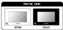

natural_image
Front view of a white electronic device labeled 'KO.COM' with control panel and buttons (no readable text beyond branding)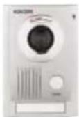
□KC-MC32

□KC·C62
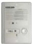
□KC-MC22

□KC-MC11

Contents
■ Cautions for safety 4
■ Specifications 6
■ Product functions and features 6
■ Installation location 6
■ Components of product 7
■ Name and functions of each part 7
■ Camera installation 8
■ Product connection diagram 10
■ Instructions for operation 11
Cautions for Safety
For safe use, please stick to the following cautions.
- Please, save this manual after reading these instructions carefully. - Read and understand all instructions to set up rightly.
- This Cautons for Safety may include items that are not contained in specifications of the product that consumer purchases.
• If you need assistance with the set-up or operation, please contact with A/G center.
The important marks in the manual,
To help our customers to understand this manual, to prevent any personal injury or property damage, some marks are used in the manual.
The marks and the drawing signs are below. Please, understand the marks before reading the manual
The meaning of the drawing signs.
| Sign to snow what not to do | Misnanding the device with ignoring this sign may result in serious injury or death. |
| Misnanding the device with ignoring this sign may result physician injury or material damage. | |
| Sign to tell you, I've you should listen the instructions. | Sign to tell you that you read more shorten and long high mileage, clock shock, clock warning! |
| Sign to tell you for you can't dozessbe his cru. | Sign to tell you that you must unplug the unit. |
Caution
- Cautions for set-up

• The law limits destroying the power lines to an authorized person from government. The work from an unauthorized person causes fire or electric shock.
- Place this unit securely on a stable surface. Serious damage and/or injury may result if the unit falls
• Do not set up this unit near the leading place because I may expose you to dangerous voltages or other risks.
• Even if your product is water proof, do not install it, sentled place of water leakage, which can a short circuit
• The work of disinforcing vares needs skills and experiences. So please, for assistance, contact your dealer or call service center.

• The communication lines should be pull in being instant from the power source. This may result in the use of line, electric shock and communication disorder.
• Selling the communication lines in a high humid place such as outside without any profession from rain causes the communication disorder.
* Keep the book at the wall-mounted device sale. The book may cause the physical injury.

+ Think about the thickness and quality of wall material. The unqualified material may move the device tail

Cautions for Use
• Do not overload on the device.

Cautions for Repairs and Maintenance
- Keep the mode of the device clean. Having the dust made without any cleaning for a long time causes the use necessary, could your order or service order to get cleaning service
- I know to a device when you want to check the price. If there is no plug, please turn off the circuit breaker
* Unplug this device when you try to move it to another place. If the electric line is connected inside of the unit, please contact your dealer or service center.
• Do not use liquid or aerial cleaners. Use a demo clock for cleaning

Warning
Warnings for Usage
- Do not install this unit near the water and dust, for example, in a bathroom or near the washing machine. It caused the end electric shock.
Do not install the unit near the 1st, for example, near kitchen sink, book or the line.
- Do not install near the nodous gar such as Hydrogen Sulfida, metal power end the like.

- Do not give any damage, break and modify the plug. Overloading, heating, cutting causes the damage.
- Do not place the plug near the heater. The damaged code causes fire and electric shock. Do not put the power code when unplugging
- The damaged code causes the and elastic shock. Must pull with plus. Do not touch with wet hands, it causes the elastic shock.
* Do not use any other volume, except the marked regular voltage.
- Do not use the power terminal at the unit to other electric device except the designed device.
- Do not install the unit of the leaking piece if it doesn't have any waterproof mask. Do not install the unit when the power is on
* Instal the circuit breaker after checking the safety such as electric shock and leakage. Turn of the power before you install or A/S

+ Check the suitability of the lines for inditing when you use the existing lines,
- Do the wiring work by using the designed material.
• Connect the electric wire with the designed wave and ground.
- Do not connect with any other devices except the designed devices to compose the system.

- Unp. electric wire and communication lines from the units before moving to another place,
Cautions for Use

- This unit is not designed for security purpose. - Do not handle the unit with the wet hands.
- Do not place a pot with water or a small metal material on the Units
- Do not cover the venting opening or put any metal material in the unit. - Open the main gate after checking ID: the image and sound system can not work. Call A6
- During fundamentals, avoid using this unit. - There may be a remote risk of an electric shock from lightning.
- Do not modify the unit
• Do not disassemble the back and cabinet power

Cautions for Abnormality

- Unplug this unit, from plug socket and refer servicing to an authorized service center when the following conditions occur:
• I would have been spilled into the unit. 4 he and does not work remotely by closing the opening instructions
- If the unit exhibits a delta change in performance. - If the unit has been dropped or physically damaged.
Caution
Safety Instructions, Warnings and Cautions of Each System
- Do not disassemble this unit at will as this device is composed by procedure parts. - Install the unit by following the set-up instructions of Kason,
- Do not touch or insert any foreign substances for example, ticker, magnetic, opener and the live
- Make L-Type at the end of wire as the rain can effect on the system by following the wire during the rainy season.
Videophone
- Separate the AC/DC lines with the hook of the wall-mounted type when insulating. - Connect the lines after peeling the wires properly
• Do not distribute signal line with AC line. • Use the designed driver to connect the lines to terminal
- Do not clean the LCD with the damp cloth for cleaning. Use the only dry and soft bath. - Do not install the main gate monitor at the leaking piece,
© Things You Need to Know
• This product is designed as a home voicephone and cannot use continuously live monitor camera.
- I there is temperature difference between inner part of camera and surrounding dew condensation occurs on camera lens and may disturb image.
I dew condensation is removed from current lens image quality recovers
- While LED light examination range is narrower than camera shot range at night, so there is a case amount of light at night than any.
So it is difficult to see the tape in low illumination condition due to noise increases on screen, but it is not from detect.
- Monitor screen liquid crystal pane is not in defect when some pixels always light or black out.
• Please install monitor and camera over from away. Also avoid installing all a place with too much nose, because too much nose around camera causes phone call inferiorly
• Do not place an object within 20cm in front of monitor. It causes phone call latency, especially because microphone is installed at the top of monitor.
- If strong light such as sunlight flows into camera module, screen saturation for stronger mark and image shaking might occur.
This is not a defect, so please do not install camera where a direct ray of light do not flow it possible.
Cautions
• In some cases there is occurrence of product destruction, malfunction, noise mixing and picture quality deterioration due to many of other items induced
valaga or thunder with communication wiring of monitor/cbsman, monitor/extended monitor.
Do not wire with power line such as outdoor wiring or AC power, or phone and other tools.
• You cannot use if you incorrectly write the AC voltage between monitor/camera, monitor/extended monitor. Call the store or agency where you purchased
this product and consult to solve the problem
Before that unstable damage might be caused due to authorizing AC voltage on communication wiring of monitor/camera, monitor/extended monitor
• Do not ever dispatch the product. I may cause electrocution accident when touching high-voltage circuit inside his product
- Outside power authoring this product must be continued at product description and use mixed values. However that higher voltage is authorized, unlike damage might be caused due to product destruction.
• Power must be connected to domestic voltage product sales, voltage consent, or inner wiring.
ll connected to other mouse power or inverter-type power: product destruction, noise mixing, and picture disorder for may occur
- Do not drop in a product. Glass is used for monitor and might break, or cause other circuit inferiorly.
In such case, immediately turn down the power switch, and call to consult agency or store in which this product was purchased.
- If related near transmission antennas such as broadcasting station, electric wave may mix and cause picture distortion or voice mixing.
- Avoid installing near track with strong dichromagnetic waves such as microwaves and cell phones, or if may cause picture distortion.
• Do not install monitor in following places.
① Above or around water heater, rice socket, heater ② Floor exposed to direct rays of the sun ③ Place with temperature below OC such as cold alone
Place with high humidity such as bathroom, bathroom, heated room
Place with a lot or gas, dust, smoke. Chargous place with springs of water or chemicals
- Do not wipe with insecticide, drugs or chemicals such as thinner and alcohol, or if may damage
the surface of his product.
- Beware of occurrence of image quality deterioration or malfunction from cause of humidity due to
pereferior of chemicals or water, no camera is used here.
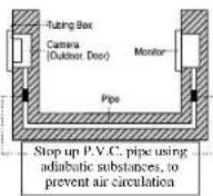
- As in the picture, it prevents temperature difference of camera (busode) and monitor (trade), and
• Cimare the best of the first 4th year Limited to be partly lazy.
• When product is tested in winter below 5°C, war for approximately 2 hours to correct. Dew transformer
in motor and center use to temper more other effects made and outside may cause product defect.
AVOC FLOWING TAKAO AND CHAPAN. It was clearly expanded to turn of the 2nd floor market in
Fig. 10. Occurring
Specifications
| TYPE | connection condition | railway line type and distance | ||||
| Line type | cross section hf | 0.3 | 0.5 | 0.6 | CAT5 | |
| Diameter of h | 0.6 | 0.8 | 1.0 | |||
| Distance | monitor × camera monitor × extension monitor | 100 | 120 | 150 | 100 | [ml] |
*Power consumption: On standby : 0.5V±20%, in communication: 10.5V±10%, in door aperture : 5V±10%
■ Specifications ■ Max wiring distance
| Model number | KCV-D372 |
| Power | DC12V=35V |
| Assurance temperature | 0°C ~ 40°C |
| Communication system | Standard type |
| LCD | 7 Digital LCD (W/DC / PAL, Also switching) |
| Wiring | Common: 2 wires (Non polarity)Extension monitor: 2 wires (Litter) |
| Mount type | Surface mount. |
| Dimension | 222 KW × 44 TH × 26 Ømm |
Product functions and features
- Display product working condition with OSD: Display cell condition, monitor condition, speaking condition, open door condition, Tin, Bright error message on OSD
- When no signal on image, converts to standby condition
- Very low consumption of electric power in standby: 0.7W of electric power consumed in standby condition, reducing electric charges.
- Use of Digital 7LCD Panel: Image is very clear and quality excision due to use of digital LCD Panel.
- Nonpolar 2 wire method between camera and monitor: Can be easily installed due to nonpolar 2 wire method between cameras and monitors.
- Extension monitor's 2 wire method: Extension monitor can be easily installed with 2 wire polar.
- Long distance wiring: Can install up to 150m between camera and monitor.
- Can connect door opener to monitor and camera
1) Can connect DC door opener to camera. 2) Can connect DC type door opener to monitor. 3) Power of simultaneous function of door opener connected to camera and monitor. - Automatic centrifugation test of connection between camera and monitor
- Automatic connection with connection between cameras and monitor
: Connect wiring between camera and monitor, authorize power, and when normally wired, "too-doc" sound (ft times) will be on, if disconnected or camera is malfunctioning, "too-doc/too-doc" sound (2 times) will be on for 5 seconds, and screen error (Please check camera or connection message will be on as LED switches all on monitor, enabling to confirm wiring condition between camera and monitor.
* Turn AC power switch CH, ON before taking measures for above causes.
Installation location

■ Monitor installation location
Standard monitor installation height is about 1,500mm where screen center is at eye level in his case, well hanging metal center (center of plung) is 1,450mm above ground level. Standard installation height
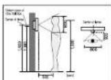
■ Camera installation location
Camera installation in height Standard camera installation height is when lens is about 1,400mm above the floor. In this case, camera stock center (bring box) is above 1,380mm above ground level. Standard installation in height
The above angle of view is based on the KO-362 camera. Two numbers were shown to the angle of view.
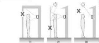
■ Caution of camera installation
- Avoid installing corners exposed to direct ray of light and sun. - Remove backlight and defence of visitor's face, which means illumination about. - Avoid installing corners in places such as the following picture. 1) Place highlighting sky as background 2) Place with white wall reflecting direct ray of light 3) Place with direct ray of light
■ Monitor installation
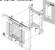
Directly connecting cut-all power cord with power wire If Do not do such electric work on your own installing product in the way requires reliance on electric installation man with electric work license. 2 Intake with mounting pipe while cutting of power cord and connecting with power wire so electric wire must do not expose. Damad intersection exposed electric wire cause tin or electric shock worker.
3) Such electric work requires connection after Ieroplan of supplied power.
1) Remove wall-hanger bracket metal behind monitor.
2) install wall-hanger bracket metal on 1 type box or wall with attached VIs.
3) Connect wiring to monitor back terminal referring to product connection diagram.
4) Hang marillar on wall-hanging metal, and fix marillar on wall-hanger brocket metal using attached Vire
5) Plus marker's power plus into consent and check to add if the power switch is [ON].
on the left side @ monitor.
Components of product
■ Monitor components
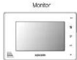
A Wall Hangar Frame


DC 12/V Adapter


DC Door Lock Wire
- Screw for fixing monitor - Wall Hanger Flying Screws
Name and functions of each part
■ The front side
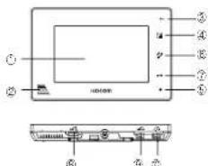
① Monitor screen (LCD) : Output of image sent from camera
② Speaker ③ Microphone
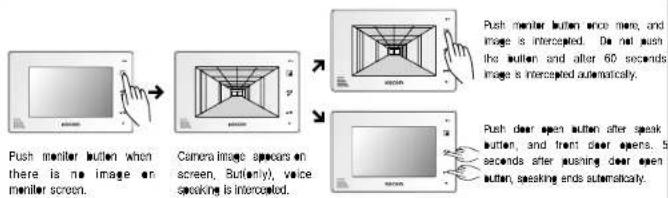
④ Monitor button: Push this button to check around camera when inside, and image is shown for 60 seconds. Using interpreted balance camera and imaging
(Voice intercepted between camera and phone) © Motion lamp. When there is cal. light cameras of
- Motion lamp: When there is call from camera of
pcntor motion it lickers and switches on when on call.
⑥ Speak button: Use this button to star / stop speaking
⑦ Open door button: Use this burton to open front door with connected door switch.
⑧ Brightness adjustment volume : Adjusting LCD screen brightness to use.
■ The Back side
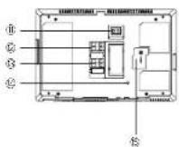
Call volume adjustment switch: Adjusting call sound in 3 steps
high, medium, low to use.
* Cannot adjust call sound to "none"
① Speaking volume adjustment switch - Adjust speaking volume transmitted from camera to monitor up 2 steps, hirs, medium
transmitted from cable (e monitor in 5 steps ring), motion,
© DC door
12. Camera terminal: Connects camera with 2 wire con
d) Extension monitor terminal: Compact extension monitor with
2 wire nonpolar.
Color adjustment volume: Adjust color on LCD screen (in shipment.
adjusted to standard color)
⑤ Power input section : nout DC power and bc power cord
Components of product
■ Door Camera components
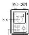
Speaker Call button

Main body

Screws for fixing main body on the wall.

Screes for being camera to main frame supporter

upward adjusting supporter for long angle
[KC-MC22]


Main beer supporter
4x10mm body supporter

4x16rm camera
[KC-MC32][KC-MC11]

Speaker Call button

Man body supporter

[Unreadable]
Screws for fixing main body on the wall
Screen for living cancer in main frame supporter

1. wench

812403

Man body supporter
※Please check the Model Name of your door camera.
![KC-MC22 CAMERA [KC-MC22] Non Polarity MONITOR 34 3 3 3 3 3 3 3 3 3 FG Non Polarity Power Supply P.S. DC Electric Door Lock 1RED : LINE 1 Monitor 2ORANGE : LINE 2 Connection 3BLACK : DOOR 1 Door Lock 4BROWN : DOOR 2 Connection 5GREEN : FG ※ Only one Electric door lock should be connected to the door camera or monitor.](/content/2026/06/1281922/images/6034bdb2a4e9d98651491eb231bc14bcaa6daaa934c2955277f2f36a61139e15.jpg)
Camera installationCamera insta
*Please check the Model Name of your door camera.
![KC-C62 CAMERA [KC-C62] Non Polarity MONITOR Non Polarity Power Supply PS DC Electric Door Lock AC/DC Electric Door Lock Power Supply PS Monitor extension Only one Electric door lock should be connected to the door camera or monitor.](/content/2026/06/1281922/images/78ecfe45c2589d1d221fa8c3d3d1989f248a0fe8d4cd864d15a862b47de8af1e.jpg)
KC-MC11
![[KC-MC11] Non Polarity Non Polarity FG Non Polarity Power Supply P.S. DC Electric Door Lock AC/DC Electric Door Lock Power Supply P.S. Monitor extension Only one Electric door lock should be connected to the door camera or monitor.](/content/2026/06/1281922/images/421877dab00a8c2bd3ffe043c3cab7af814eb4a63c5c77bc19a68921f37a00c6.jpg)
KC-MC32
![[KC-MC32] Non Polarity FG Non Polarity Power Supply P.S. DC Electric Door Lock × Only one Electric door lock should be connected to the door camera or monitor. Non Polarity Polarity AC/DC Electric Door Lock Power Supply P.S. Monitor extension](/content/2026/06/1281922/images/9cf604631e1d4a90cbeb57df3bb9c3fe11757abb81b481ba85aa1554b5db4e3e.jpg)
Product connection diagram
If you connect other types of cable in the middle of communication cable wiring between monitor/camera, monitor/extension monitor or divide parallel 2wick to 1 pattern, image screen may shake or quality may deteriorate.
Also, wire not used in communication wiring must be deleted or connect product.

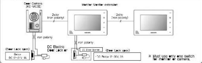
■ Product connection diagram
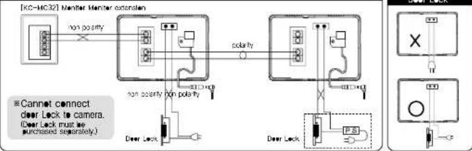
- Beware in installation of pushing open door button, which causes DC switch connected to camera and AC (or DC) switch connected to monitor to motion.
- Connect DC switch and AC switch movement power separately. Switch connecting to camera can only use DC switch, and switch connecting to monitor can use AC or DC type.
※Door opener caution total product wiring diagram Connection method, Method for use as below
Wiring diagram
flowchart
graph LR
    A["Door Camera (KC-WC32)"] -->|2nd/100% priority| B["Monitor Monitor extension"]
    B -->|2nd/100% priority| C["Monitor (DC) with 100% priority"]
    D["DC Electric Door Lock or"] -->|non priority| E["DC Box Upper"]
    E --> F["DC Box Lower"]
    G["(Dear Lock spec)"] --> H["(Dear Lock spec)"]
    I["(Dear Lock spc)"] --> J["(Dear Lock spc)"]
    K["DC 2V-30V, IA"] --> L["(DC 2V-30V, IA)"]
    M["DC 2V-30V, IA"] --> N["(DC 2V-30V, IA)"]
    O["DC 2V-30V, IA"] --> P["(DC 2V-30V, IA)"]
    Q["DC 2V-30V, IA"] --> R["(DC 2V-30V, IA)"]
    S["DC 2V-30V, IA"] --> T["(DC 2V-30V, IA)"]
    U["DC 2V-30V, IA"] --> V["(DC 2V-30V, IA)"]
    W["DC 2V-30V, IA"] --> X["(DC 2V-30V, IA)"]
    Y["DC 2V-30V, IA"] --> Z["(DC 2V-30V, IA)"]
    AA["DC 2V-30V, IA"] --> AB["(DC 2V-30V, IA)"]
    AC["DC 2V-30V, IA"] --> AD["(DC 2V-30V, IA)"]
    AE["DC 2V-30V, IA"] --> AF["(DC 2V-30V, IA)"]
    AG["DC 2V-30V, IA"] --> AH["(DC 2V-30V, IA)"]
    AI["DC 2V-30V, IA"] --> AJ["(DC 2V-30V, IA)"]
    AK["DC 2V-30V, IA"] --> AL["(DC 2V-30V, IA)"]
    AM["DC 2V-30V, IA"] --> AN["(DC 2V-30V, IA)"]
    AO["DC 2V-30V, IA"] --> AP["(DC 2V-30V, IA)"]
    AQ["DC 2V-30V, IA"] --> AR["(DC 2V-30V, IA)"]
    AS["DC 2V-30V, IA"] --> AT["(DC 2V-30V, IA)"]
    AU["DC 2V-30V, IA"] --> AV["(DC 2V-30V, IA)"]
    AW["DC 2V-30V, IA"] --> AX["(DC 2V-30V, IA)"]
    AY["DC 2V-30V, IA"] --> AZ["(DC 2V-30V, IA)"]
    BA["DC 2V-30V, IA"] --> BB["(DC 2V-30V, IA)"]
    BC["DC 2V-30V, IA"] --> BD["(DC 2V-30V, IA)"]
    BE["DC 2V-30V, IA"] --> BF["(DC 2V-30V, IA)"]
    BG["DC 2V-30V, IA"] --> BH["(DC 2V-30V, IA)"]
    BI["DC 2V-30V, IA"] --> BJ["(DC 2V-30V, IA"]
    BK["DC 2V-30V, IA"] --> BL["(DC 2V-30V, IA"]
    BM["DC 2V-30V, IA"] --> BN["(DC 2V-30V, IA"]
    BO["DC 2V-30V, IA"] --> BP["(DC 2V-30V, IA"]
    BQ["DC 2V-30V, IA"] --> BR["(DC 2V-30V, IA"]
    BS["DC 2V-30V, IA"] --> BT["(DC 2V-30V, IA"]
    BU["DC 2V-30V, IA"] --> BV["(DC 2V-30V, IA"]
    BW["DC 2V-30V, IA"] --> BX["(DC 2V-30V, IA"]
    BY["DC 2V-30V, IA"] --> BZ["(DC 2V-30V, IA"]
    CA["DC 2V-30V, IA"] --> CB["(DC 2V-30V, IA"]
    CC["DC 2V-30V, IA"] --> CD["(DC 2V-30V, IA"]
    CE["DC 2V-30V, IA"] --> CF["(DC 2V-30V, IA"]
    DG["DC 2V-30V, IA"] --> DH["(DC 2V-30V, IA"]
    DI["DC 2V-30V, IA"] --> DJ["(DC 2V-30V, IA"]
    DK["DC 2V-30V, IA"] --> DL["(DC 2V-30V, IA"]
    DM["DC 2V-30V, IA"] --> DE["(DC 2V-30V, IA"]
    FD["DC 2V-30V, IA"] --> ED["(DC 2V-30V, IA"]
    EF["DC 2V-30V, IA"] --> GF["(DC 2V-30V, IA"]
    GH["DC 2V-30V, IA"] --> ID["(DC 2V-30X SA)"]
    IJ["DC 2Wx6789"] --> AJ["(DC Box Upper)"]
    AK["DC Box Lower"] --> AL["(DC Box Lower)"]
Wiring diagram on monitor
flowchart
graph TD
    A["Door Lock"] -->|non polarity| B["Monitor Monitor extension"]
    B -->|polarity| C["Control Switch"]
    C --> D["P.S."]
    D --> E["Output"]
    style A fill:#f9f,stroke:#333
    style B fill:#ccf,stroke:#333
    style C fill:#cfc,stroke:#333
    style D fill:#fcc,stroke:#333
    style E fill:#ffc,stroke:#333
Door opener wiring diagram on door camera in DC

flowchart
graph LR
    A["non polarity"] --> B["Monitor"]
    C["DC Deer Lock (Adapter)"] --> B
    B --> D["Monitor extension"]
    D --> E["..."]
    style A fill:#f9f,stroke:#333
    style C fill:#ccf,stroke:#333
    style B fill:#cfc,stroke:#333
    style D fill:#fcc,stroke:#333
    note right of D: "Cannot connect deer Lock to monitor."
    note right of B: "non polarity"
    note right of D: "DC Deer Lock (Adapter)"
Instructions for operation
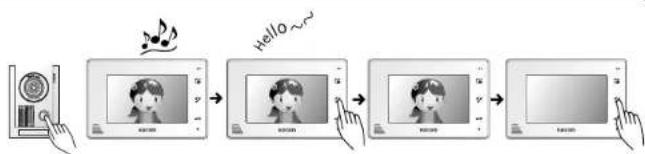
■ Calling from camera
flowchart
graph LR
    A["Read into CD"] --> B["Music Note: Note: Note is not present"]
    B --> C["Hello ~"]
    C --> D["View: Please click the note"]
    D --> E["Next Step: Click to show the next note"]
    E --> F["End: Screen with icon"]
Push call button from camera. You can hear call sound from all connected monitors, and camera image comes out on screen, ①Push monitor button to enter the door for 60 seconds. ②Push speak button to check the call,
Push open door button to Call ends when you push open front door. About 5 open door button and seconds after pushing the speak button once again, button, call ends automatically.
※ Open door opener works only in speaking condition, and does not work when no image is on screen,
■ Using monitor tool
■ Monitor screen time
- Not pushing speak (or monitor) button after calling from camera : 15 seconds
Pushing monitor button to check around camera : 60 seconds
Push speak button to speak with camera : 3 minutes
■ Screen brightness, call sound, speak volume adjustments
- Screen brightness adjustment : Screen brightness variable to volume
Call sound adjustment : Call sound variable in 3 steps (high/medium/low).
- Speak volume adjustment - Speak sound (monitor output voice) variable in 3 steps (high/medium/low)

- To receive after-sales service, have the following
- KOCOM
- HOMEMANAGER
- KCV-D372MANUAL
- WIRE COLOR
- HANDSFREE VIDEOPHONE
- Contents
- Cautions for Safety
- For safe use, please stick to the following cautions.
- Caution
- - Cautions for set-up
- Cautions for Use
- Cautions for Repairs and Maintenance
- Warning
- Warnings for Usage
- Cautions for Abnormality
- Safety Instructions, Warnings and Cautions of Each System
- Videophone
- © Things You Need to Know
- Cautions
- Product functions and features
- Installation location
- Components of product
- Name and functions of each part
- Camera installationCamera insta
- Product connection diagram
- ■ Product connection diagram
- Instructions for operation
- ■ Monitor screen time
- ■ Screen brightness, call sound, speak volume adjustments
Brand : Syscom
Model : KCVD372W
Category : Intercom