
CS500PLCN100 - Powerline Adapter KONIG - Free user manual and instructions
Find the device manual for free CS500PLCN100 KONIG in PDF.


| Product Type | Powerline Adapter (CPL) |
| Brand | KONIG |
| Model | CS500PLCN100 |
| Network Interface | 1 x RJ45 Ethernet port 10/100 Mbps |
| Standard | HomePlug AV (up to 200 Mbps) |
| LED Indicators | Power, PLC Link (red/orange/green), Ethernet Link |
| Buttons | Security (pairing), Reset |
| Power Supply | Mains 100-240 V, 50/60 Hz (direct wall outlet connection) |
| Installation | Plug and Play, no configuration required |
| Safety | Do not open the device, do not expose to water, unplug if problem occurs |
| Maintenance | Clean with a dry cloth, no solvents or abrasive products |
| Repairability | Only qualified technician intervention |
| Warranty | Void if unauthorized modification or alteration |
| Operating Temperature | Room temperature (avoid areas of excessive heat) |
| Compatibility | Must be paired with at least one other HomePlug AV compatible adapter |
| Box Contents | Powerline adapter, Ethernet cable, quick start guide |
Frequently Asked Questions - CS500PLCN100 KONIG
User questions about CS500PLCN100 KONIG
0 question about this device. Answer the ones you know or ask your own.
Ask a new question about this device
Download the instructions for your Powerline Adapter in PDF format for free! Find your manual CS500PLCN100 - KONIG and take your electronic device back in hand. On this page are published all the documents necessary for the use of your device. CS500PLCN100 by KONIG.
USER MANUAL CS500PLCN100 KONIG
CS500PLCN100

MANUAL (p. 2)
Nano HomePlug 500Mbps
MODE D'EMPLOI (p. 13)
Nano HomePlug 500 Mbps
MANUALE (p. 23)
Nano HomePlug 500 Mbps
HASZNÁLATI ÚTMUTATÓ (o. 34.)
Nano HomePlug 500 Mbit/s
Nano HomePlug 500 Mbit/s
MANUAL DE USO (p. 29)
Nano HomePlug 500 Mbps
KÄYTTÖOHJE (s. 39)
Nano HomePlug 500 Mbps
Chapter 1: HomePlug Power Line Installation
1.1 System Diagram
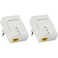
Add high-speed Internet access to any room in your home with this Nano HomePlug AV Ethernet Bridge. You can play HD movies, music, online multi-player games and much more.
Note: This Nano HomePlug AV Ethernet Bridge needs to pair with at least one other HomePlug AV compatible device in order to create a working system.
![graph TD A["Modem / Router"] --> B["Internet Connection"] C["Ethernet connection"] --> B B --> D["CS500PLCN100"] B --> E["Ethernet cable"] B --> F["Power line"] B --> G["CS500PLCN100"]](/content/2026/06/1280370/images/859dddd4f5e9dec3cfe0c6cabc9763f2cf332630494c40b3bee62b749287c83c.jpg)
1.2 Casing details
Casing details / Status lights
The front of the device contains 3 types of status lights (see below)

Power
Light on: Power is on
Light off: Power is off
PLC link
The PLC (Power Line) link light will indicate the overall speed of your network with 3 colors.
Red: Minimum connection speed / weak signal with speed less than 50 Mbps
Orange: Normal signal with standard network speed between 50 – 100 Mbps
Green: Excellent signal strength with optimal network speed of 100 Mbps+ Off: No connection / No activity
Ethernet link
Solid green: 10/100 port linked
Off: Ethernet link not active
Bottom details

Security button
This function is designed to generate an individual HomePlug network group in a multi-node environment. Please refer to the "Individual HomePlug Network Setup" section below for more details.
Reset button
This function is used to clear all data and restore all settings to the factory default values.
Note: The HomePlug must be plugged in to restore all factory settings. Hold the Reset button until the status light begins to flash.
1.3 Initial setup
The CS500PLCN100 is a Plug-and-Play device. You can easily use the device without any complicated configurations and settings. You can also use the device to connect network devices like computers and game consoles directly. You can also connect devices like Blu-Ray Disc™ player to a router or modem for internet access.
Connect the HomePlug AV Ethernet Bridge to a computer or modem / router:
- Plug one end of the Ethernet cable into an Ethernet port on the bottom of the HomePlug.
-
Plug the HomePlug into an AC wall power outlet near the device you want to connect to. (Note: Do not plug this HomePlug into a power strip that has surge protection. Doing so will degrade the power line performance. For best performance, plug the HomePlug directly into a wall outlet.)
-
To connect to a computer, plug the other end of the Ethernet cable into an available Ethernet port of your computer.
-
To connect to a modem / router, plug the other end of the Ethernet cable into an available Ethernet port of your modem / router.
-
Make sure that the PLC link light is solid green.
-
Your HomePlug is now connected in the network.
Chapter 2: Individual HomePlug AV Network Setup (optional)
Since all HomePlug units do have a default security key, they will automatically be linked to all other HomePlug units sharing the same electrical lines. If there are other HomePlug units in the building (such as in an office or apartment building), you may want to create your own individual HomePlug network group so that other HomePlug units cannot connect to your network. The section below describes how to use the security button for reconfiguration in some situations.
2.1 Creating a new individual HomePlug AV Network (Network AB)
Two unassociated HomePlug units (A and B) are forming a network.
![graph LR A["Computer"] -->|Data Line| B["Device A"] B -->|Data Line| C["Device B"] C -->|Data Line| D["Laptop"]](/content/2026/06/1280370/images/2b25d9c6ecbdc819e215ad52ef7f366ca13e47181eb2ad30c428bda46e070482.jpg)
The procedure is as follows:
- Press and hold the security button on HomePlug A for about 10 seconds. Release when the power light flashes. The password to HomePlug A has just been erased. It must be linked to your network to adopt the new network security key.
- Do the same for HomePlug B.
- Now, HomePlug A and B are now networked separately.
- Press and hold the security button on HomePlug A for 2 seconds and then release.
- The power light of bridge A starts to flash.
- Within 120 seconds press and hold the security button on HomePlug B for 2 seconds and then release.
- Both HomePlug A and B are now networked together.
2.2 Adding HomePlug C to an existing Network AB (Network ABC)
![graph TD A["Desktop Computer"] -->|Wireless| C["Network Equipment"] B["Laptop"] -->|Wireless| C C -->|Wireless| A A -->|Wireless| B B -->|Wireless| C C -->|Wireless| A](/content/2026/06/1280370/images/e6d1b9cec83f57106f68c132be3fc7a3f1787924f1055586b494927f4db3261a.jpg)
The procedure is as follows:
- Press and hold the security button on HomePlug C for about 10 seconds. Release when the power light flashes. The password to HomePlug C has just been erased. It must be linked to your network to adopt the new network security key.
- Press and hold the security button on HomePlug C for 2 seconds. The power light starts to flash.
- Within 120 seconds, press and hold the security button on HomePlug C for 2 seconds and then release.
- HomePlug A, HomePlug B and HomePlug C are now networked.
2.3 Removing HomePlug B from HomePlug A and C network and join HomePlug D and E (Network BDE)
![graph TD subgraph_Remove_HomePlug_B["Remove HomePlug B from Network ABC to Network DE"] A1["Computer"] --> A2["A"] A2 --> A3["User icon"] A3 --> A4["User icon"] A4 --> A5["User icon"] A5 --> A6["User icon"] A6 --> A7["User icon"] A7 --> A8["User icon"] A8 --> A9["User icon"] A9 --> A10["User icon"]…](/content/2026/06/1280370/images/ee43e7667ef28da4fe90e50e47e6e480ad1a20da0986e367f5c8976caf491b1f.jpg)
The procedure is as follows:
- Press and hold the security button on HomePlug B for about 10 seconds. Release when the power light flashes. The password to HomePlug B has just been erased and HomePlug B removes itself from HomePlug A and C.
- Press and hold the security button on HomePlug D for 2 seconds. The power light starts to flash.
- Within 120 seconds after the power light on HomePlug D starts to flash, press and hold the security button on HomePlug B for 2 seconds and then release.
- HomePlug B and HomePlug D are now connected to each other. Therefore, together with HomePlug E, they will form the network BDE.
Chapter 3: Troubleshooting & disclaimer
If your HomePlug AV Ethernet Bridge has difficulty communicating with each other, check the following:
• Try power cycling the unit by unplugging it from the wall socket for 10 seconds and plug it in again.
- Hold the Reset button on each HomePlug for 15 seconds and try to re-connect. The HomePlug's light will flash, and the HomePlug will be reset and attempt to link using the default factory settings.
- Try plugging the HomePlug into an adjacent power outlet.
- The HomePlug works better when plugged directly into the wall power outlet. Connecting the HomePlug to a power strip or surge protector may degrade the network performance or completely stop network signals.
- This HomePlug should not be used in areas with excessive heat.
- Certain florescent or incandescent lights are noise sources for the electrical wiring and can degrade the performance.
- If your building has more than one circuit breaker box, your HomePlug may not be able to connect between the different circuit breaker boxes. In this case, connect one HomePlug to a power outlet located on each of the circuit boxes. Connect an Ethernet cable between each of the HomePlug units to link the different HomePlug together. This will allow the HomePlug units from different circuit breaker boxes to be connected.
- To enter standby mode, simply remove the Ethernet cable from the HomePlug and wait about 3 minutes.
Disclaimer: This product was designed to be plugged directly into a wall socket as shown in the diagram below. Any other use may hamper the function of the product.


Safety precautions:



To reduce risk of electric shock, this product should ONLY be opened by an authorised technician when service is required. Disconnect the product from mains and other equipment if a problem should occur. Do not expose the product to water or moisture.
Maintenance:
Clean the product only with a dry cloth.
Do not use cleaning solvents or abrasives.
Warranty:
Any changes and/or modifications to the product will void the warranty. We cannot accept any liability for damage caused by incorrect use of this product.
Disclaimer:
Designs and specifications are subject to change without notice. All logos, brands and product names are trademarks or registered trademarks of their respective holders and are hereby recognized as such.
Disposal:

- This product is designated for separate collection at an appropriate collection point. Do not dispose of this product with household waste.
- For more information, contact the retailer or the local authority responsible for waste management.
This product has been manufactured and supplied in compliance with all relevant regulations and directives, valid for all member states of the European Union. It also complies with all applicable specifications and regulations in the country of sales.
Formal documentation is available upon request. This includes, but is not limited to: Declaration of Conformity (and product identity), Material Safety Data Sheet and product test report.
Please contact our customer service desk for support:
via website: http://www.nedis.com/en-us/contact/contact-form.htm
via e-mail: service@nedis.com
via telephone: +31 (0)73-5993965 (during office hours)
NEDIS B.V., De Tweeling 28, 5215 MC 's-Hertogenbosch, THE NETHERLANDS
DEUTSCH
Kapitel 1: HomePlug Powerline Installation
1.1 Systemdiagramm
1.2 Behuizingdetails
Behuizingdetails / Statuslampjes
Buton de siguranță



- CHAPTER 1: HOMEPLUG POWER LINE INSTALLATION
- 1.1 SYSTEM DIAGRAM
- 1.2 CASING DETAILS
- CASING DETAILS / STATUS LIGHTS
- POWER
- PLC LINK
- ETHERNET LINK
- BOTTOM DETAILS
- SECURITY BUTTON
- RESET BUTTON
- 1.3 INITIAL SETUP
- CHAPTER 2: INDIVIDUAL HOMEPLUG AV NETWORK SETUP (OPTIONAL)
- 2.1 CREATING A NEW INDIVIDUAL HOMEPLUG AV NETWORK (NETWORK AB)
- 2.3 REMOVING HOMEPLUG B FROM HOMEPLUG A AND C NETWORK AND JOIN HOMEPLUG D AND E (NETWORK BDE)
- CHAPTER 3: TROUBLESHOOTING & DISCLAIMER
- SAFETY PRECAUTIONS
- MAINTENANCE
- WARRANTY
- DISCLAIMER
- DISPOSAL
- DEUTSCH
- KAPITEL 1: HOMEPLUG POWERLINE INSTALLATION
- 1.1 SYSTEMDIAGRAMM
- 1.2 BEHUIZINGDETAILS
- BEHUIZINGDETAILS / STATUSLAMPJES
- BUTON DE SIGURANȚĂ
Brand : KONIG
Model : CS500PLCN100
Category : Powerline Adapter