BF15A (2000) - Outboard motor Honda - Free user manual and instructions
Find the device manual for free BF15A (2000) Honda in PDF.


| Product Type | Outboard Motor |
| Brand | Honda |
| Model | BF15A (2000) |
| Year | 2000 |
| Power Output | 15 HP (11.2 kW) |
| Engine Type | 4-Stroke |
| Displacement | 345 cc |
| Number of Cylinders | 2 |
| Fuel Type | Unleaded Gasoline |
| Starting System | Manual Recoil (Electric Start Optional) |
| Control System | Tiller Handle |
| Gear Shift | Forward, Neutral, Reverse |
| Weight | Approx. 47 kg (103.6 lbs) |
| Overall Length | 680 mm (26.8 in) |
| Overall Width | 500 mm (19.7 in) |
| Overall Height | 1100 mm (43.3 in) |
| Transom Height | 508 mm (20 in) |
| Fuel Tank Capacity | 12 L (3.2 gal) |
| Cooling System | Water Cooling |
| Propeller Type | Aluminum 3-Blade |
| Maintenance Interval | Oil change every 100 hours, Spark plug annually |
| Safety Features | Engine stop switch lanyard, overheat alarm |
Frequently Asked Questions - BF15A (2000) Honda
User questions about BF15A (2000) Honda
0 question about this device. Answer the ones you know or ask your own.
Ask a new question about this device
Download the instructions for your Outboard motor in PDF format for free! Find your manual BF15A (2000) - Honda and take your electronic device back in hand. On this page are published all the documents necessary for the use of your device. BF15A (2000) by Honda.
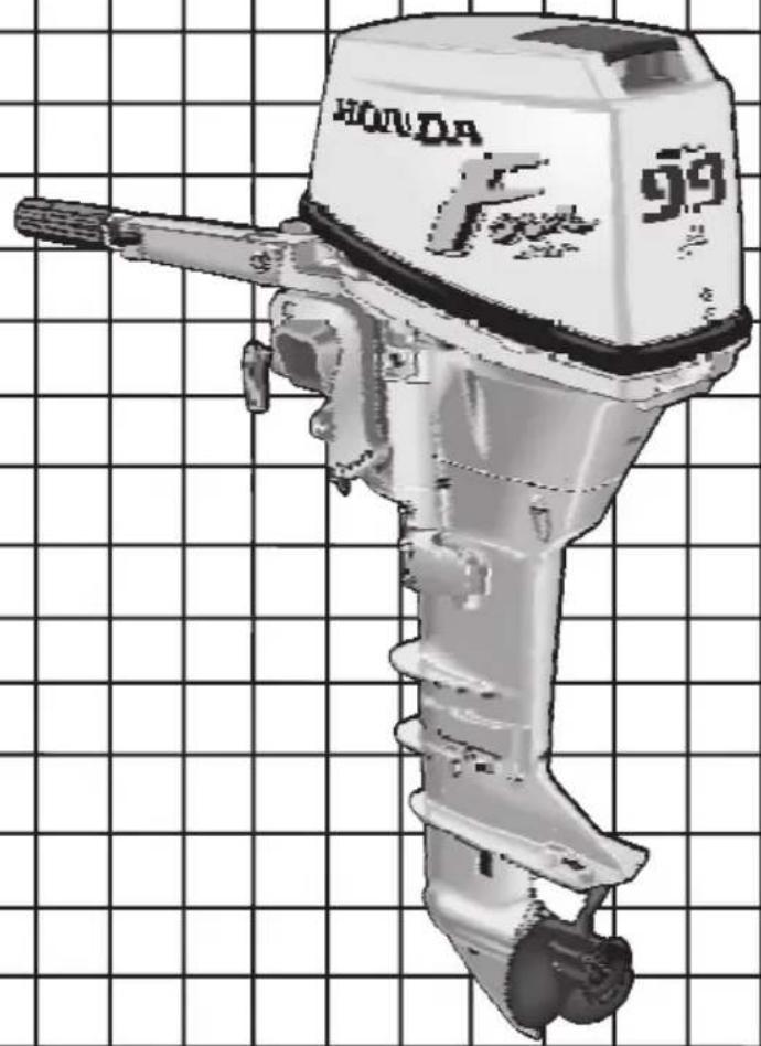
USER MANUAL BF15A (2000) Honda
Includes Remote Control Supplement
natural_image
Illustration of a Honda F-99 electric shaver on a grid background (no text or symbols on the device itself)
Keep this owner's manual handy, so you can refer to it at any time.
This owner's manual is considered a permanent part of the outboard motor and should remain with the outboard motor if resold.
The information and specifications included in this publication were in effect at the time of approval for printing. Honda Motor Co., Ltd. reserves the right, however, to discontinue or change specifications or design at any time without notice and without incurring any obligation whatever. No part of this publication may be reproduced without written permission.
INTRODUCTION
Congratulations on your selection of a Honda outboard motor. We are certain you will be pleased with your purchase of one of the finest outboard motors on the market.
We want to help you get the best results from your new outboard motor and to operate it safely. This manual contains the information on how to do that; please read it carefully.
As you read this manual, you will find information preceded by a NOTICE symbol. That information is intended to help you avoid damage to your outboard motor, other property, or the environment.
We suggest you read the warranty policy to fully understand its coverage and your responsibilities of ownership. The warranty policy is a separate document that should have been given to you by your dealer.
When your outboard motor needs scheduled maintenance, keep in mind that your Honda servicing dealer is specially trained in servicing Honda outboard motors. Your Honda servicing dealer is dedicated to your satisfaction and will be pleased to answer your questions and concerns.
Best Wishes,
Honda Motor Co., Ltd.
A FEW WORDS ABOUT SAFETY
Your safety and the safety of others are very important. And using this outboard motor safely is an important responsibility.
To help you make informed decisions about safety, we have provided operating procedures and other information on labels and in this manual. This information alerts you to potential hazards that could hurt you or others.
Of course, it is not practical or possible to warn you about all the hazards associated with operating or maintaining a outboard motor. You must use your own good judgment.
You will find important safety information in a variety of forms, including:
- Safety Labels — on the outboard motor.
- Safety Messages — preceded by a safety alert symbol ⚠ and one of three signal words, DANGER, WARNING, or CAUTION.
These signal words mean:

DANGER
You WILL be KILLED or SERIOUSLY HURT if you don't follow instructions.

WARNING
You CAN be KILLED or SERIOUSLY HURT if you don't follow instructions.

CAUTION
You CAN be HURT if you don't follow instructions.
- Safety Headings — such as IMPORTANT SAFETY INFORMATION.
- Safety Section — such as OUTBOARD MOTOR SAFETY.
- Instructions — how to use this outboard motor correctly and safely.
This entire book is filled with important safety information — please read it carefully.
CONTENTS
OUTBOARD MOTOR SAFETY 7
IMPORTANT SAFETY INFORMATION....7
Operator Responsibility 7
Refuel With Care 8
Carbon Monoxide Hazard 8
SAFETY LABEL LOCATIONS 9
CONTROLS & FEATURES 10
COMPONENT & CONTROL LOCATIONS 10
CONTROLS 12
Engine Stop Switch 12
Choke Knob 12
Throttle Grip 13
Throttle Friction Knob 13
Gearshift Lever 14
Recoil Starter Grip 14
Electric Starter Button 14
Steering Friction Bolt 15
Tilt Lever 15
Transom Angle Adjusting Rod 16
Engine Cover Lock Lever 16
Fuel Priming Bulb 17
Fuel Cap Vent Knob 17
FEATURES 1/
Fuel Gauge 17
Oil Pressure Indicator Light 17
Water Check Hole 17
Anode 18
Overrev Limiter 18
INSTALLATION 19
INSTALLATION POSITION 19
INSTALLATION HEIGHT 19
OUTBOARD MOTOR ATTACHMENT 20
MOTOR ANGLE FOR CRUISING 21
MOTOR ANGLE ADJUSTMENT 21
BATTERY CONNECTIONS 22
Models With Electric Starter 22
Models Without Electric Starter 22
Battery Installation 23
EMERGENCY PROCEDURES 23
Connections to the Battery 24
BEFORE OPERATION 25
ARE YOU READY TO GET UNDER WAY? 25
Knowledge 25
Safety Apparel 25
IS YOUR OUTBOARD MOTOR READY TO GO? 25
Safety Inspection 26
Maintenance Inspection 26
OPERATION 27
SAFE OPERATING PRECAUTIONS....27
BREAK-IN PROCEDURE 27
PORTABLE FUEL TANK PLACEMENT AND CONNECTIONS ..... 27
Fuel Tank Placement 27
Fuel Hose Connections 28
Fuel Priming....28
STARTING THE ENGINE 29
EMERGENCY STARTING 33
STOPPING THE ENGINE....34
Emergency Engine Stopping 34
Normal Engine Stopping 34
GEAR SHIFTING 35
STEERING 36
CRUISING 37
TILTING THE OUTBOARD MOTOR 38
SERVICING YOUR HONDA OUTBOARD MOTOR 40
THE IMPORTANCE OF MAINTENANCE 40
MAINTENANCE SAFETY 41
Safety Precautions....41
TOOL KIT AND SPARE PARTS 42
MAINTENANCE SCHEDULE 43
REFUELING 44
FUEL RECOMMENDATIONS....45
COOLING SYSTEM CLEANING AND FLUSHING 45
Cleaning and Flushing With the Flush Kit....46
Cleaning and Flushing Without the Flush Kit 46
ENGINE OIL LEVEL CHECK 47
ENGINE OIL CHANGE 48
ENGINE OIL RECOMMENDATIONS 49
GEAR OIL LEVEL CHECK 49
GEAR OIL CHANGE 50
LUBRICATION 51
SPARK PLUG SERVICE 52
FUEL FILTER REPLACEMENT....53
RECOIL STARTER ROPE INSPECTION 55
ANODE REPLACEMENT 55
PROPELLER REPLACEMENT 56
HELPFUL TIPS & SUGGESTIONS 57
STORING YOUR OUTBOARD MOTOR....57
Storage Preparation 57
Storage Precautions 59
Removal From Storage 60
TRANSPORTING....60
TAKING CARE OF UNEXPECTED PROBLEMS 61
ENGINE WILL NOT START 61
ENGINE OVERHEATS 62
BATTERY DOES NOT CHARGE AND ELECTRIC STARTER
(applicable models) DOES NOT OPERATE 63
Fuse Replacement 63
SUBMERGED MOTOR 64
TECHNICAL & CONSUMER INFORMATION 66
TECHNICAL INFORMATION......66
Serial Number Locations 66
Carburetor Modification for High Altitude Operation 67
Oxygenated Fuels 68
Emission Control System Information 69
Specifications....71
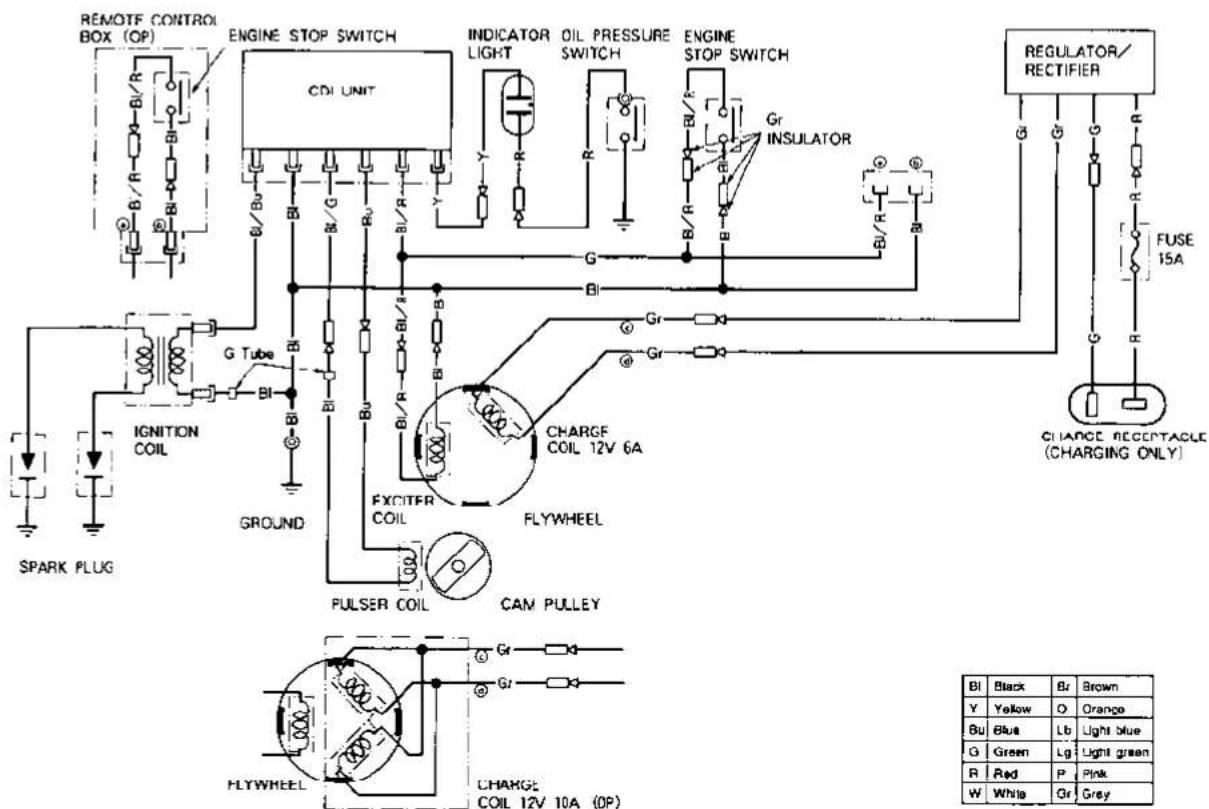
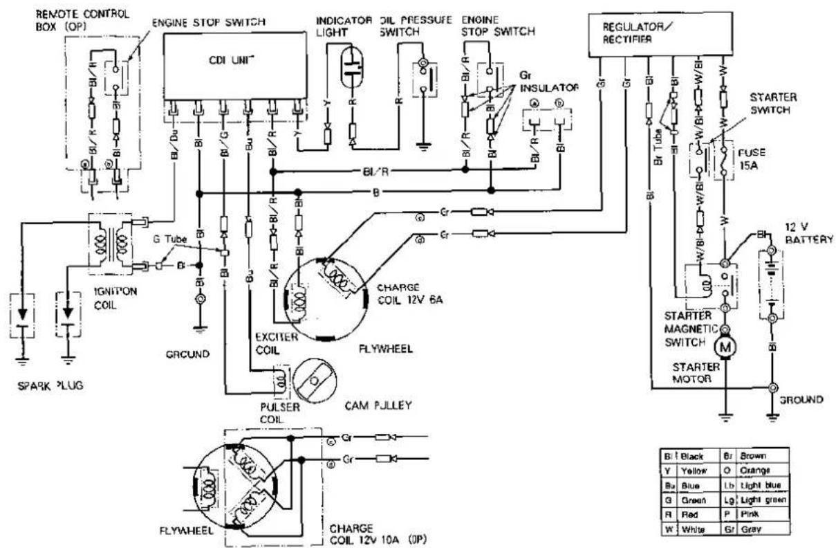
WIRING DIAGRAMS 74
CONSUMER INFORMATION 76
Honda Publications 76
Warranty Service Information 77
INDEX 78
QUICK REFERENCE INFORMATION......Inside back cover
OUTBOARD MOTOR SAFETY
IMPORTANT SAFETY INFORMATION
Honda BF9.9A and BF15A outboard motors are designed for use with boats that have a suitable manufacturer's power recommendation, and other uses can result in injury to the operator or damage to the outboard motor and other property.
Most accidents can be prevented if you follow all instructions in this manual and on the outboard motor. The most common hazards are discussed below, along with the best way to protect yourself and others.
Operator Responsibility
- It is the operator's responsibility to provide the necessary safeguards to protect people and property. Know how to stop the engine quickly in case of emergency. Understand the use of all controls.
- Stop the engine immediately if anyone falls overboard, and do not run the engine while the boat is near anyone in the water.
• Always stop the engine if you must leave the controls for any reason.
- Attach the emergency stop switch lanyard securely to the operator.
• Always wear a PERSONAL FLOTATION DEVICE (PFD) while on the boat.
- Familiarize yourself with all laws and regulations relating to the boating and the use of outboard motors.
- Be sure that anyone who operates the outboard motor receives proper instruction.
- Be sure the outboard motor is properly mounted on the boat.
- Do not remove the engine cover while the engine is running.
- Do not attempt to modify the outboard motor.
- Do not remove any labels, covers, or safety devices; they are installed for your safety.
Refuel With Care
- Gasoline is extremely flammable, and gasoline vapor can explode. Refuel outdoors, in a well-ventilaed area, with the engine stopped. Never smoke near gasoline, and keep other flames and sparks away.
- Remove any portable fuel tank from the boat for refueling. Keep the portable fuel tank away from the battery or other potential spark sources.
- Refuel carefully to avoid spilling fuel. Avoid overfilling the fuel tank.
- After refueling, tighten the filler cap securely. If any fuel is spilled, make sure the area is dry before starting the engine.
Carbon Monoxide Hazard
Exhaust gas contains poisonous carbon monoxide. Avoid inhalation of exhaust gas. Never run the engine in a closed garage or confined area.
SAFETY LABEL LOCATIONS
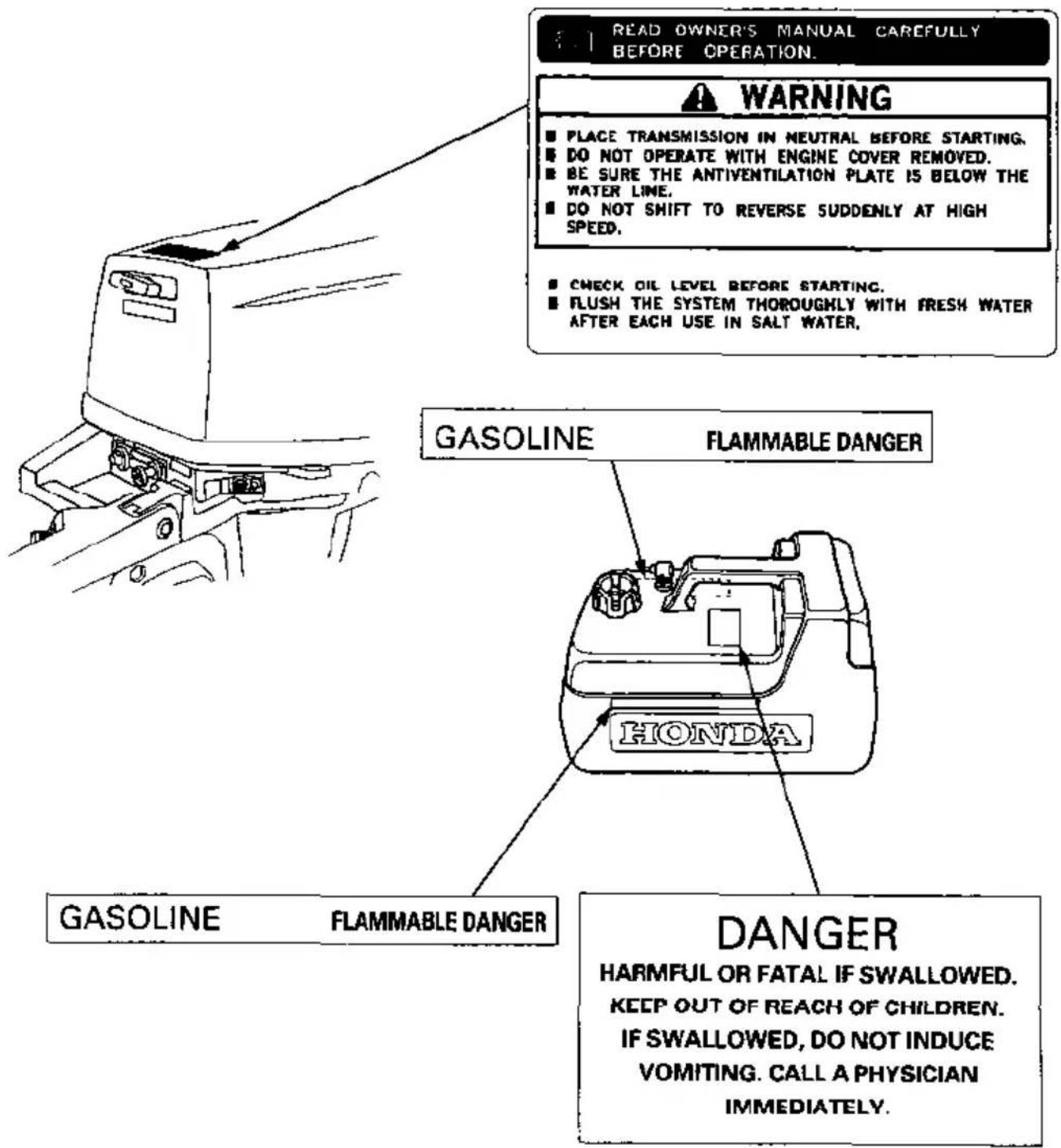
The labels shown here contain important safety information. Please read them carefully. These labels are considered permanent parts of your outboard motor. If a label comes off or becomes hard to read, contact an authorized Honda servicing dealer for a replacement.
CONTROLS & FEATURES
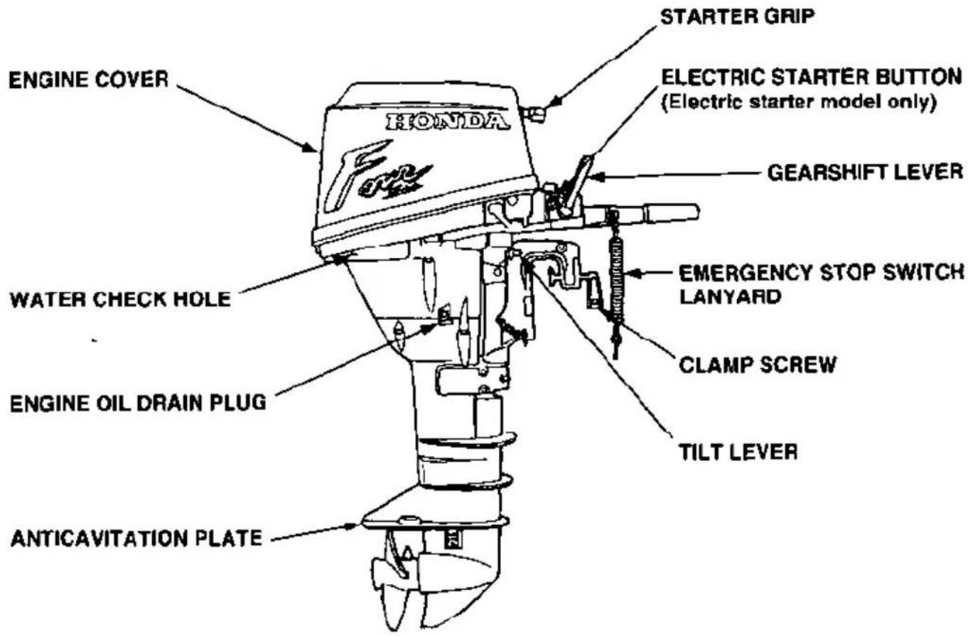
COMPONENT & CONTROL LOCATIONS
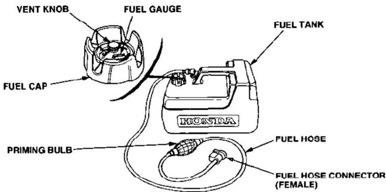
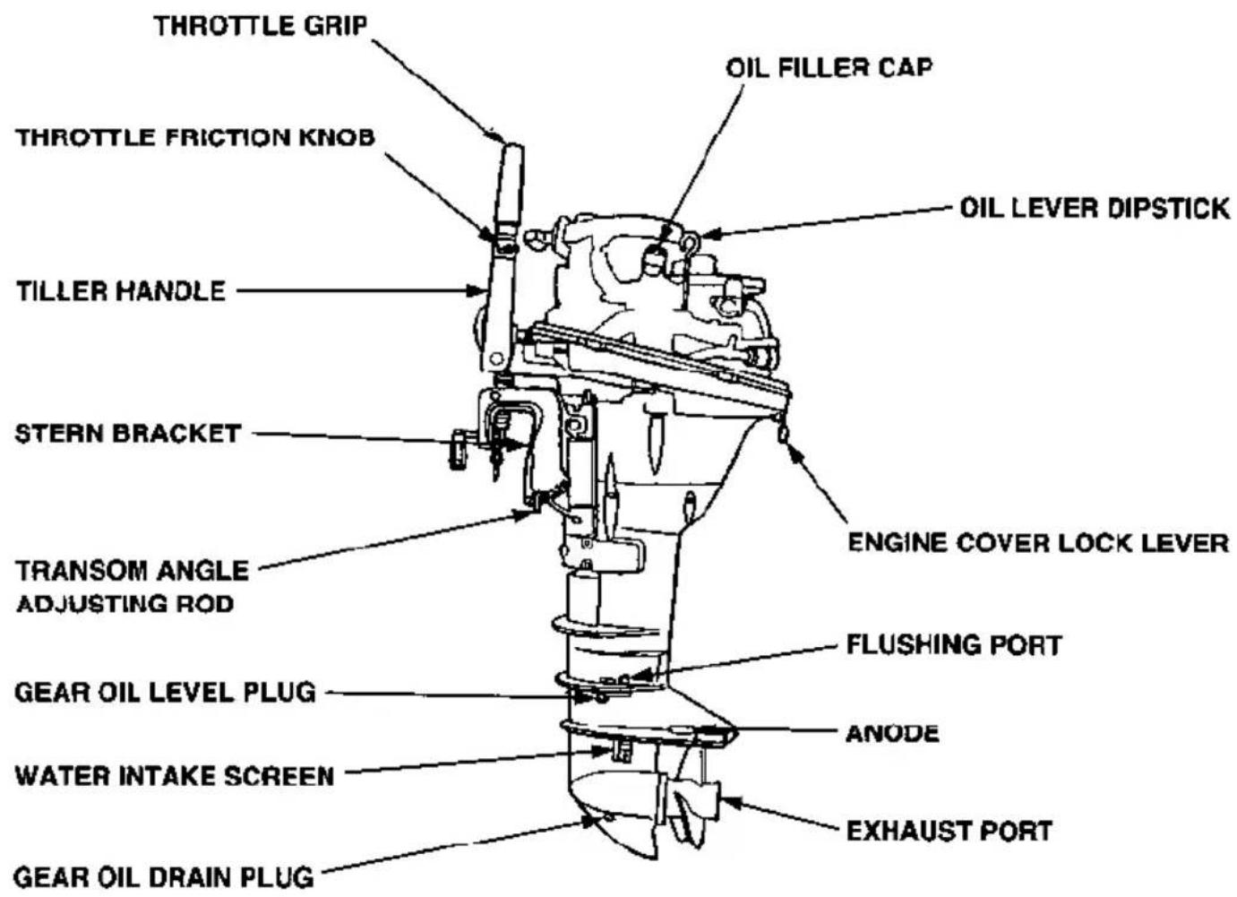
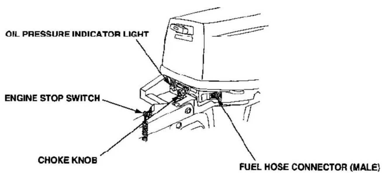
CONTROLS
Engine Stop Switch
The engine stop switch has controls for normal engine stopping and emergency engine stopping.
In normal operation, press the engine stop button to stop the engine.
A clip and lanyard system stops the engine automatically if the operator falls away from the controls.
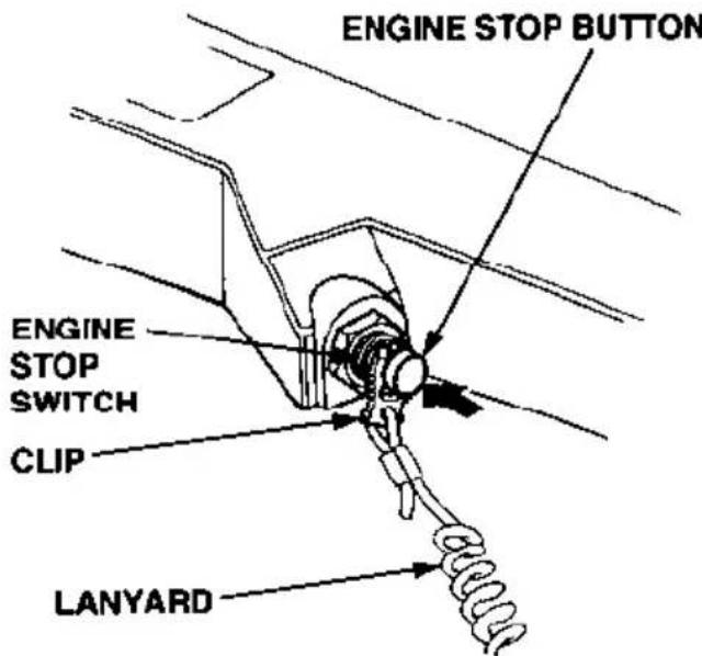
The switch clip must be inserted in the engine stop switch in order for the engine to start and run. The other end of the lanyard attaches to the operator's wrist. If the operator falls away from the controls, the lanyard pulls the clip out of the switch.
Always attach the lanyard to your wrist before operating the outboard motor.
A spare switch clip is supplied with the tool kit.
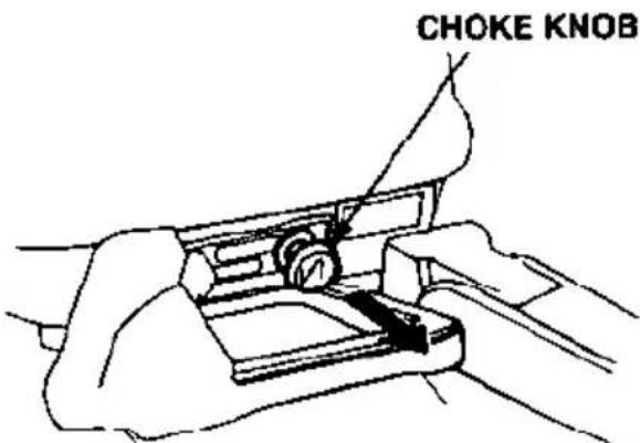
Choke Knob
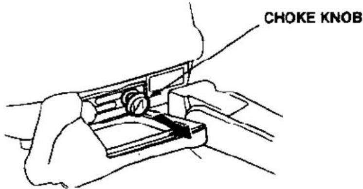
The choke knob opens and closes the choke valve in the carburetor.
The CLOSED position enriches the fuel mixture for starting.
The OPEN position provides the correct fuel mixture for operation after starting, and for restarting a warm engine.
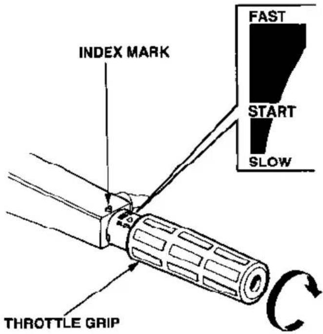
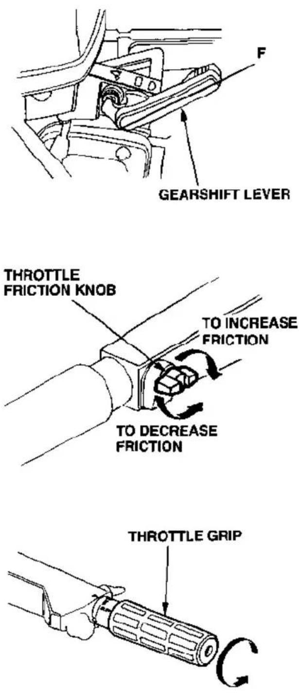
Throttle Grip
The throttle grip controls engine speed.
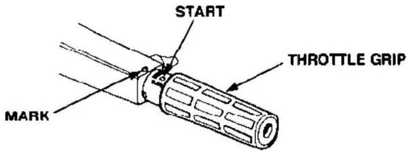
An index mark on the tiller arm indicates throttle position.
The BF9.9A gearshift mechanism limits throttle grip movement when the gearshift lever (p. 14) is in the N (neutral) position.
The BF15A gearshift mechanism limits throttle grip movement when the gearshift lever (p. 14) is in the R (reverse) or N (neutral) position.
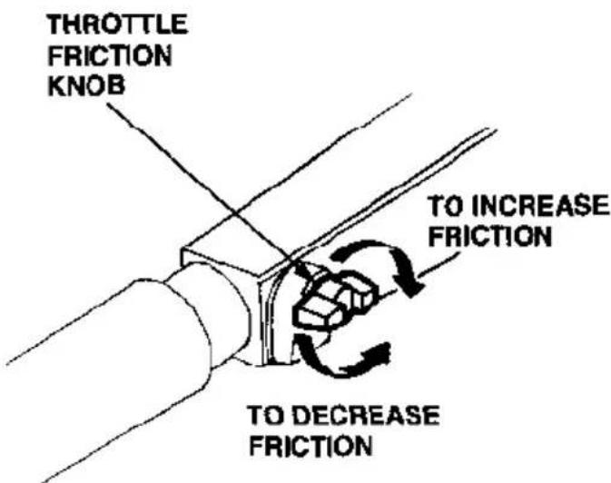
Throttle Friction Knob
The throttle friction knob adjusts resistance to throttle grip rotation.
Turn the knob clockwise to increase friction for holding a throttle setting while cruising.
Turn the knob counterclockwise to decrease friction for easy throttle grip rotation.
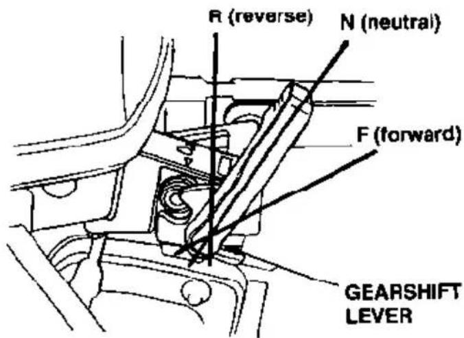
Gearshift Lever
The gearshift lever is used to select F (forward), N (neutral), or R (reverse) gears.
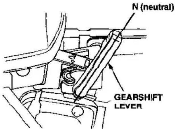
The engine can be started with the gearshift lever in the N (neutral) position only.
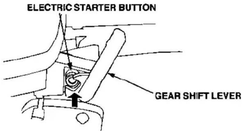
If the gearshift lever is in the F (forward) or R (reverse) position, the recoil starter will not operate, and the electric starter button (applicable models) is blocked.
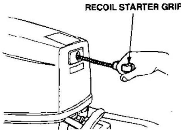
Recoil Starter Grip
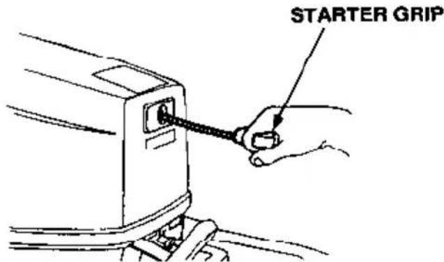
Pull the starter grip to operate the recoil starter for starting the engine manually.
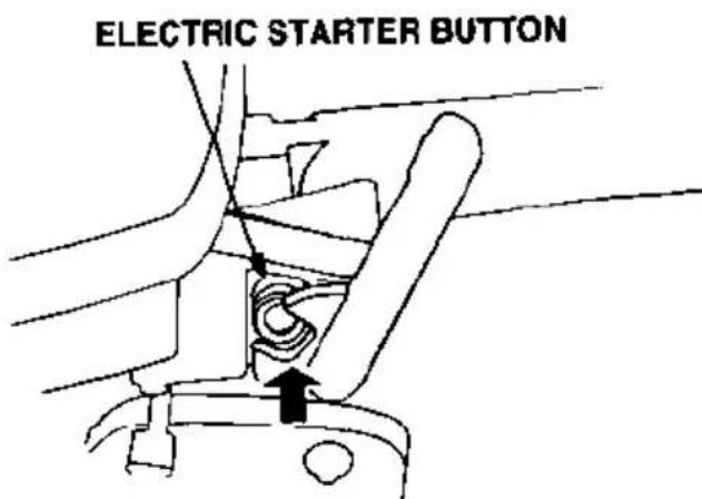
Electric Starter Button (models equipped with electric starter)
Press the starter button to start the motor.
Steering Friction Bolt
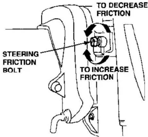
The steering friction bolt adjusts steering resistance.
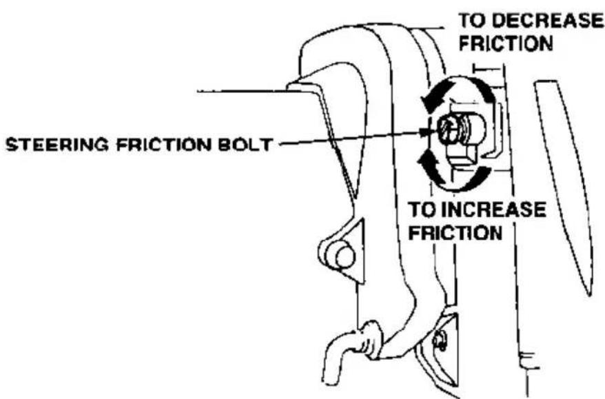
Turn the bolt clockwise to increase friction for holding a steady course while cruising or to prevent the outboard motor from swinging while trailing the boat.
Turn the bolt counterclockwise to reduce steering friction.
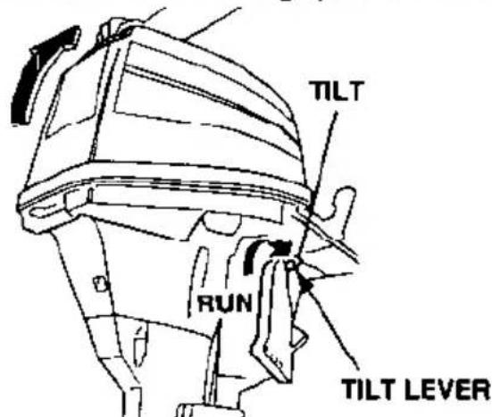
Tilt Lever
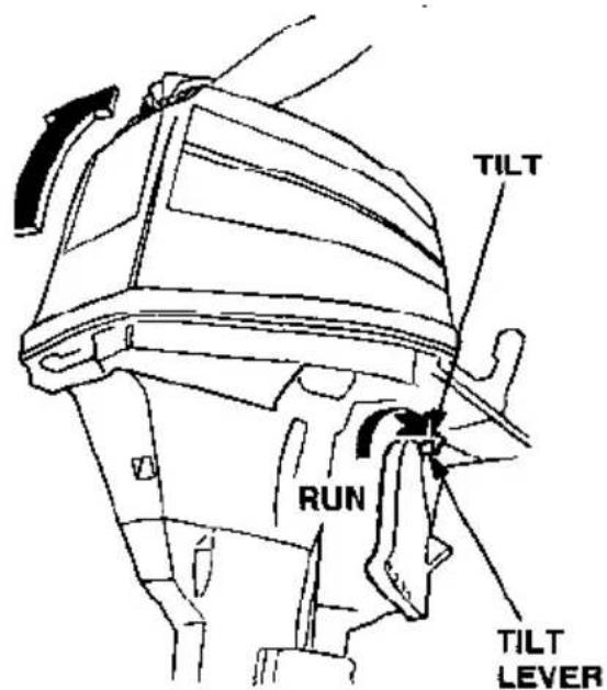
The tilt lever enables the outboard motor to be raised for shallow water operation, beaching, launching, or mooring.
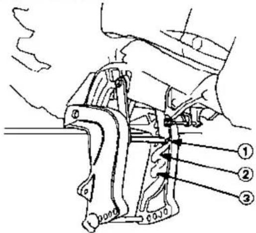
To tilt, move the lever to the TILT position, then raise the outboard motor until the tilt mechanism engages at 30°, 45° or 70° (p. 38).
To return the outboard motor to the normal running position, move the tilt lever to the RUN position, raise the outboard motor slightly to disengage the tilt mechanism, then slowly lower the engine.
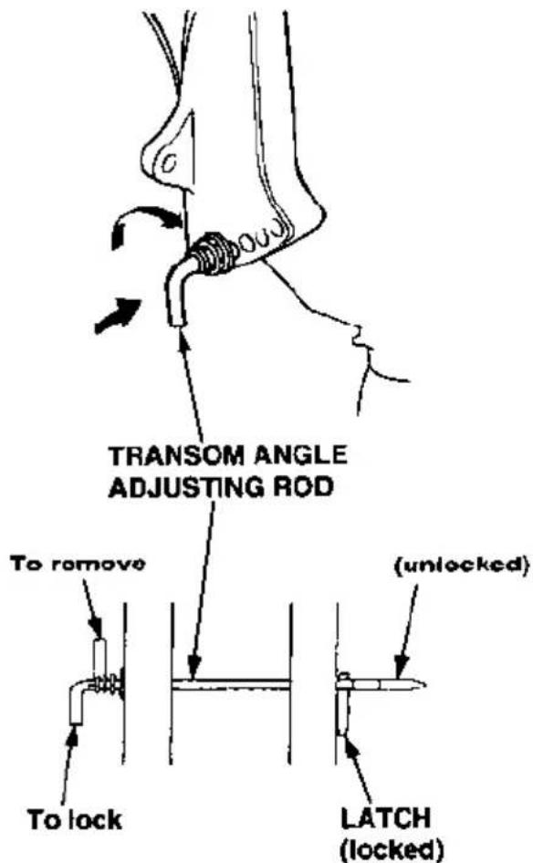
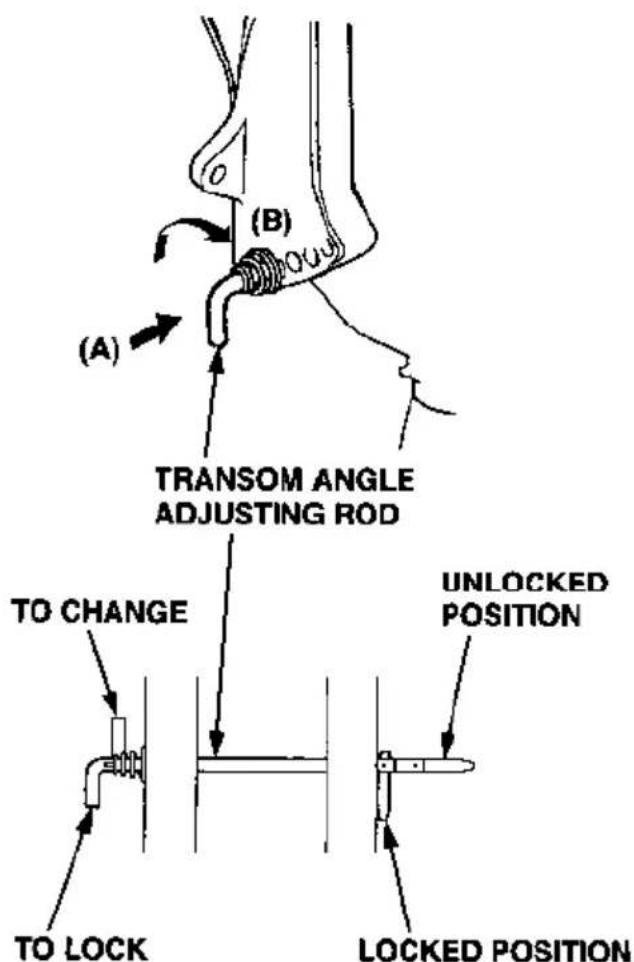
Transom Angle Adjusting Rod
The transom angle adjusting rod is used to adjust the angle of the outboard motor in the normal operating position (see page 21).
To adjust, first tilt the outboard motor, so it is not resting on the rod.
Push the rod in, and turn the end of the rod up, so the latch will fall into line with the rod.
Remove the rod, and reinsert it in the desired position.
Push the rod in, and turn the end of the rod down, so the latch will fall to the locked position. Then release the rod.
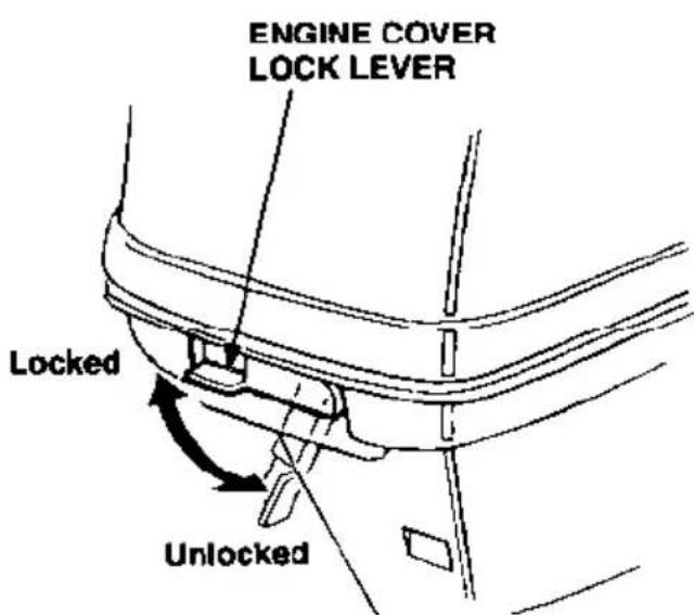
Engine Cover Lock Lever
The engine cover lock lever fastens the cover to the outboard motor.
To remove the cover, move the lever to the unlocked position, then lift off the cover.
To install the cover, position the cover on the outboard motor, then move the lever to the locked position.
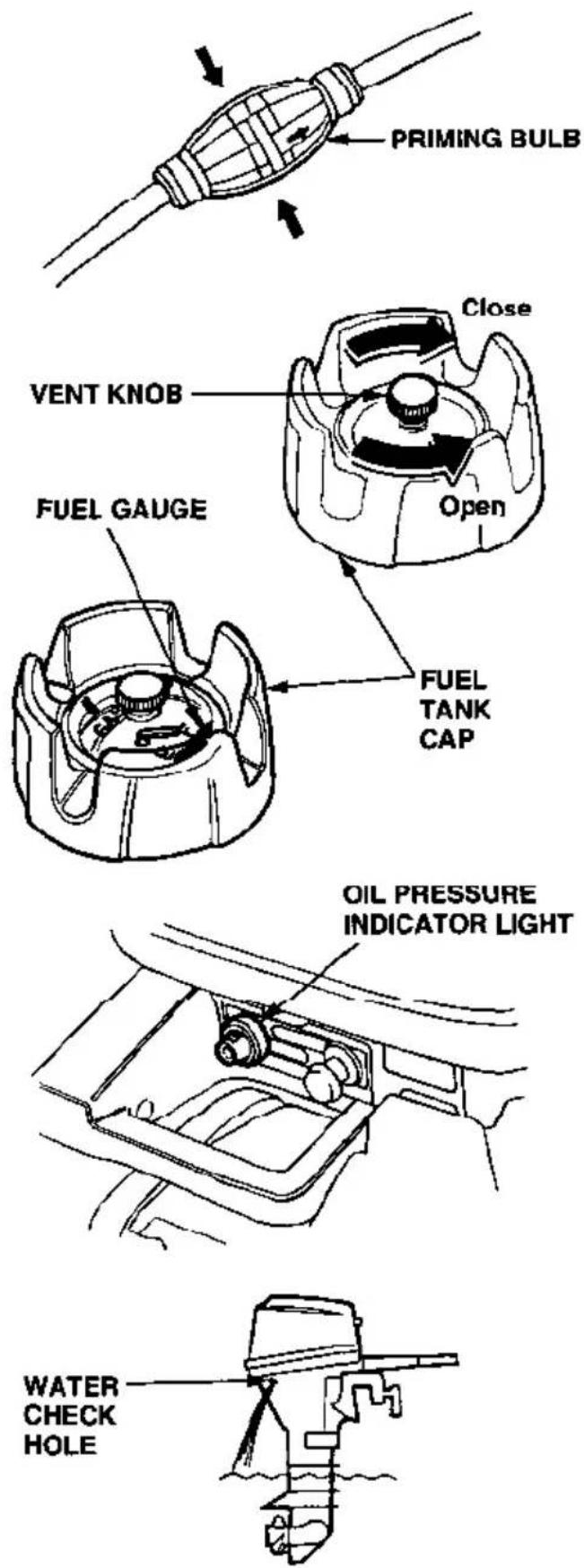
Fuel Priming Bulb
A priming bulb is built into the fuel hose that connects the portable fuel tank to the outboard motor.
Before operating the outboard motor, squeeze the priming bulb until it feels firm. This will ensure that fuel is supplied to the engine (see page 28).
Fuel Cap Vent Knob
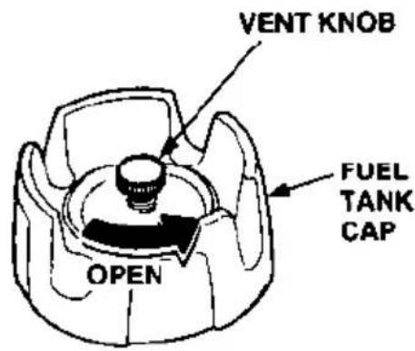
The cap is provided with a vent knob to seal the portable fuel tank for carrying it to and from the boat. Open the vent knob 2 or 3 turns before operating the outboard motor (see page 28).
FEATURES
Fuel Gauge
A fuel gauge is built into the cap of the portable fuel tank (see page 44).
Oil Prssure Indicator Light
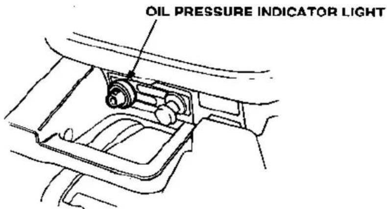
The oil pressure indicator light should remain lit while the engine is running. The light indicates that oil pressure is OK (see page 31).
Water Check Hole
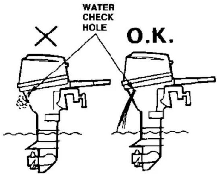
Water should flow from the water check hole while the engine is running. This shows that water is circulating through the engine cooling system (see page 32).
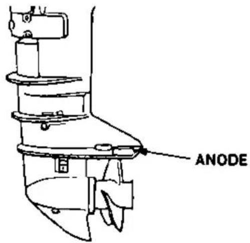
Anode
The anode is a sacrificial material which helps to protect the outboard motor from corrosion.
Overrev Limiter
The engine is equipped with an overrev limiter to prevent the possibility of mechanical damage from excessive engine speed.
The overrev limiter may be activated during operation, limiting engine speed, if the outboard motor is tilted excessively, or when ventilation occurs during a sharp turn.
If the overrev limiter is activated, check the height and angle of the outboard motor.
NOTICE
Excessive tilt angle during operation can cause propeller ventilation, overheating, and water pump damage.
INSTALLATION
It is your responsibility to choose a boat suitable for the outboard motor.
WARNING
Do not exceed the boat manufacturer's power recommendation. Damage and injury may result.
INSTALLATION POSITION
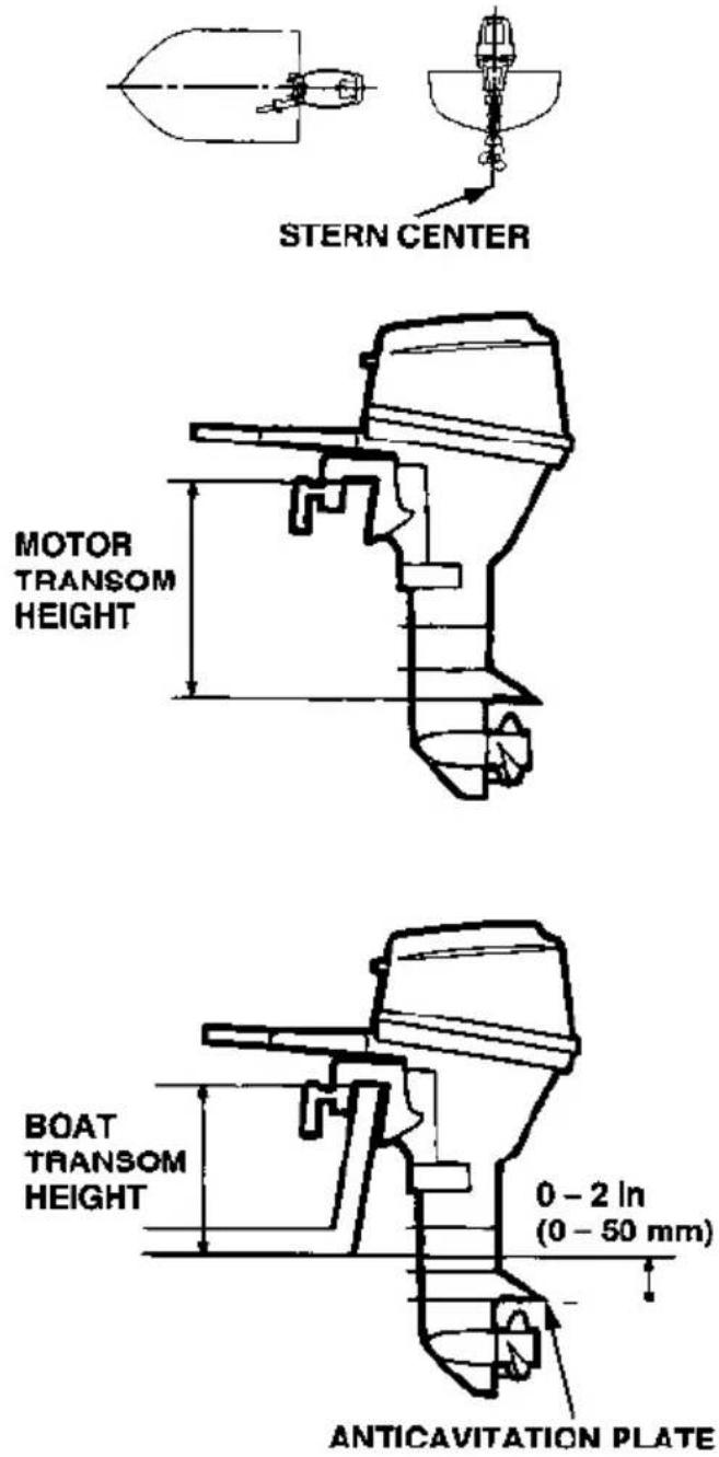
Install at the stern, at the center line of the boat.
INSTALLATION HEIGHT
For proper propeller depth and engine cooling, the boat and outboard motor transom height must match.
Three outboard motor transom heights are available. Match your boat's transom height to the outboard motor transom height shown below.
| Outboard Motor | |
| Type | Transom Height |
| Short : S | 17.3 in (440 mm) |
| Long : L | 22.4 in (570 mm) |
| Extra Long : X | 28.0 in (710 mm) |
The anticavitation plate should be 0 - 2 in (0 - 50 mm) below the bottom of the boat. With the boat in the water, loaded and motor off, the anticavitation plate should be about 3.9 in (100 mm) below the surface of the water.
NOTICE
Running the outboard motor without sufficient cooling water will damage the water pump and overheat the engine.
OUTBOARD MOTOR ATTACHMENT
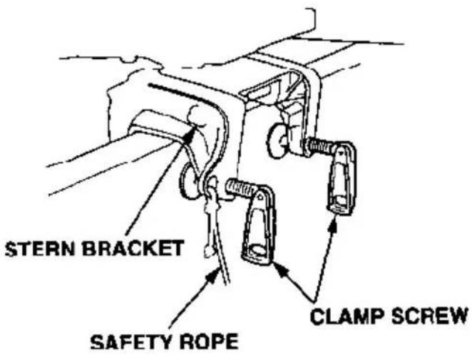
Attach the stern bracket to the trans- som and tighten the clamp screws.
NOTICE
- Before operating the boat, check the tightness of the clamp screws.
- Tie a rope through the hole in the stem bracket and secure the other end of the rope to the boat. This will prevent accidental loss of the motor.
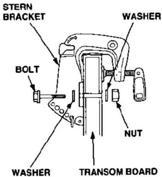
To prevent the outboard motor from falling accidentally, you may further secure the stern bracket to the trans- som board with commercially avail- able bolts, nuts and washers.
After attaching the stern bracket to the transom board, be sure to apply sealant (THREEBOND 1216 or equivalent) to the bolt holes.
This modification should be made by your authorized Honda marine dealer.
MOTOR ANGLE FOR CRUISING
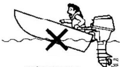
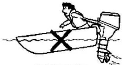
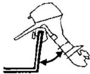
Adjust the motor so the propeller shaft is parallel with the water surface.
natural_image
Cartoon illustration of a person in a boat with a cross symbol, no text or symbols presentINCORRECT CAUSES BOAT TO "SQUAT"
natural_image
Simple line drawing of a person rowing a boat with a cross symbol on the water (no text or labels)INCORRECT CAUSES BOAT TO "PLOW"
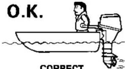
CORRECT GIVES MAXIMUM PERFORMANCE
MOTOR ANGLE ADJUSTMENT
If the propeller shaft is not parallel with the water surface, adjust by changing the transom angle adjusting rod position.
There are four adjusting stages.
-
Push in (A) the adjusting rod, twist upwards (B) and pull out to remove.
-
Inserting the rod in the proper hole, twist it down to lock.
NOTICE
To prevent damage to the motor or boat, make sure the transom angle adjusting bolt is locked.
BATTERY CONNECTIONS
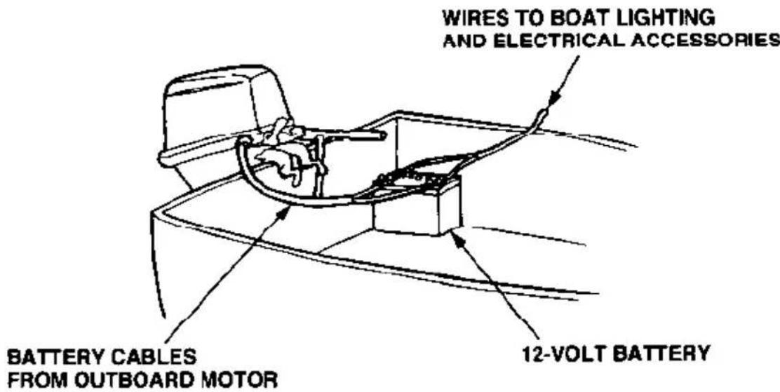
Honda BF9.9A and BF15A outboard motors produce a 12-volt, 6-ampere battery-chaging current and are equipped for connection to a 12-volt battery. The battery-charging circuit is protected by a 15-ampere fuse located in the engine compartment.
The outboard motor's 12-volt output is intended for battery charging only. Lights and electrical accessories for the boat should be connected to the battery.
Models With Electric Starter
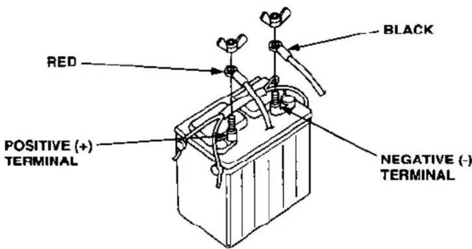
These models are equipped with battery cables. The positive (+) cable has a red band at the battery connector. The negative (−) cable has a black band at the battery connector.
For electric starter operation, use a 12-volt battery with an ampere-hour rating of at least 40 Ah.
Models Without Electric Starter
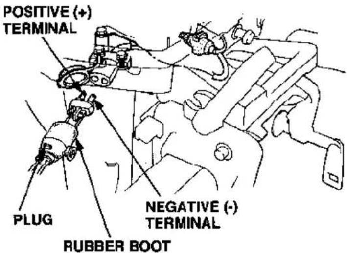
These models are equipped with a 12-volt dc battery-charging receptacle and a plug which can be wired to a 12-volt battery to power lights and electrical accessories for the boat.
The receptacle is provided with a rubber cap, which should be attached when the plug is removed, in order to keep the receptacle clean and dry.
To prepare the outboard motor for connection to a battery, pull the plug out of its rubber boot, route suitable electrical wires through the boot, and screw them to the plug positive (+) and negative (−) terminals. Coat the plug terminals with grease, and reinstall the plug in the rubber boot.
Battery Installation
Place the battery in a corrosion-resistant battery box that is securely mounted in a location away from the fuel tank and protected from water and direct sunlight.
WARNING
The battery contains sulfuric acid (electrolyte), which is highly corrosive and poisonous.
Getting electrolyte in your eyes or on your skin can cause serious burns.
Wear protective clothing and eye protection when working near the battery.
EMERGENCY PROCEDURES
Eyes — Flush with water from a cup or other container for at least 15 minutes (water under pressure can damage the eye). Immediately call a physician, local poison control center, or 911.
Skin — Remove contaminated clothing. Flush the skin with large quantities of water. Call a physician immediately.
Swallowing — Drink water or milk. Call your local poison control center or a physician immediately.
Connections to the Battery
Connect the positive (+) battery cable to the positive (+) battery terminal, then connect the negative (−) battery cable to the negative (−) battery terminal.
The negative (−) battery cable should always be removed from the battery when connecting or disconnecting the positive (+) battery cable, so tools cannot cause a short circuit if they touch a grounded part while being used on the positive (+) battery terminal fitting.
NOTICE
Be careful to avoid connecting the battery in reverse polarity, as that will damage the battery-charging system in the outboard motor.
BEFORE OPERATION
ARE YOU READY TO GET UNDERWAY?
Your safety is your responsibility. A little time spent in preparation will significantly reduce your risk of injury.
Knowledge
Read and understand this manual. Know what the controls do and how to operate them.
Familiarize yourself with the outboard motor and its operation before you get underway. Know what to do in case of emergencies.
Familiarize yourself with all laws and regulations relating to boating and the use of outboard motors.
Safety Apparel
Always wear a PFD while on the boat. Attach the emergency stop switch lanyard securely to your PFD or your wrist.
For your safety, and to maximize the service life of your equipment, it is very important to take a few moments before you operate the outboard motor to check its condition. Be sure to take care of any problem you find, or have your servicing dealer correct it, before you operate the outboard motor.
WARNING
Improperly maintaining this out- board motor, or failing to correct a problem before operation, could cause a malfunction in which you could be seriously injured.
Always perform a preoperation inspection before each operation, and correct any problem.
Safety Inspection
- Look around for signs of oil or gasoline leaks. Make sure the fuel tank is in good condition and properly secured in the boat (see page 27). Check that the fuel hose is undamaged and properly connected (see page 28). Wipe up any spills before starting the engine.
- Check the stern bracket to be sure the outboard motor is securely installed.
- Check that all controls are operating properly.
- Replace any damaged parts.
- Check that all fasteners are in place and securely tightened.
Maintenance Inspection
- Check the engine oil level (see page 47). Running the engine with a low oil level can cause engine damage.
- Check to be sure the propeller is undamaged, and the retaining nut is secured with a cotter pin (see page 56).
- Check that the anode is securely attached to the anticavitation plate and is not excessively worn (see page 55). The anode helps to protect the outboard motor from corrosion.
- Make sure the tool kit and spare parts are onboard (see page 42). Replace any missing items.
- Check the fuel level in the fuel tank (see page 44).
OPERATION
SAFE OPERATING PRECAUTIONS
To safely realize the full potential of this outboard motor, you need a complete understanding of its operation and a certain amount of practice with its controls.
Before operating the outboard motor for the first time, please review the IMPORTANT SAFETY INFORMATION on page 7 and the chapter titled BEFORE OPERATION.
For your safety, avoid starting or operating the engine in an enclosed area. Your engine's exhaust contains poisonous carbon monoxide gas which can collect rapidly in an enclosed area and cause illness or death.
BREAK-IN PROCEDURE
Proper break-in procedure allows the moving parts to wear in smoothly for best performance and long service life.
For the first 10 hours, run the outboard motor at low speed, and avoid full-throttle operation.
PORTABLE FUEL TANK PLACEMENT AND CONNECTIONS
Fuel Tank Placement
Place the portable fuel tank in a well-ventilated location, away from direct sunlight.
WARNING
Gasoline is highly flammable and explosive.
You can be burned or seriously injured when handling fuel.
- Stop the engine and keep heat, sparks, and flame away.
- Handle fuel only outdoors.
- Wipe up spills immediately.
natural_image
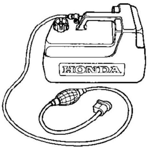
Line drawing of a Honda electric vehicle charging station with attached cable (no text or symbols)To ensure that the outboard motor will be able to draw fuel from the tank, place the tank within 6 feet of the outboard motor and not more than 3 feet below the fuel connector on the outboard motor.
Secure the portable fuel tank in the boat, so it won't move around and become damaged.
Before use, open the fuel tank vent by turning the vent knob at least 2 or 3 turns counterclockwise.
Fuel Hose Connections
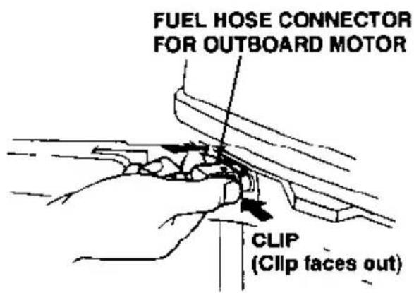
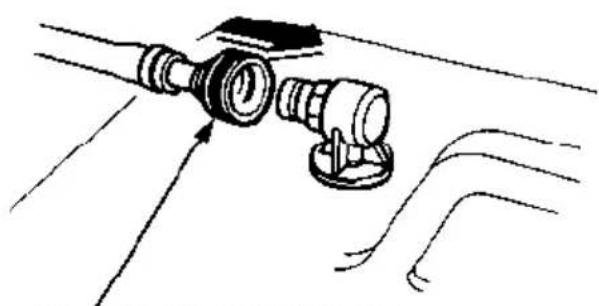
Connect the fuel hose to the tank and the outboard motor, as shown. Be sure both connectors snap securely into place.
Fuel Priming
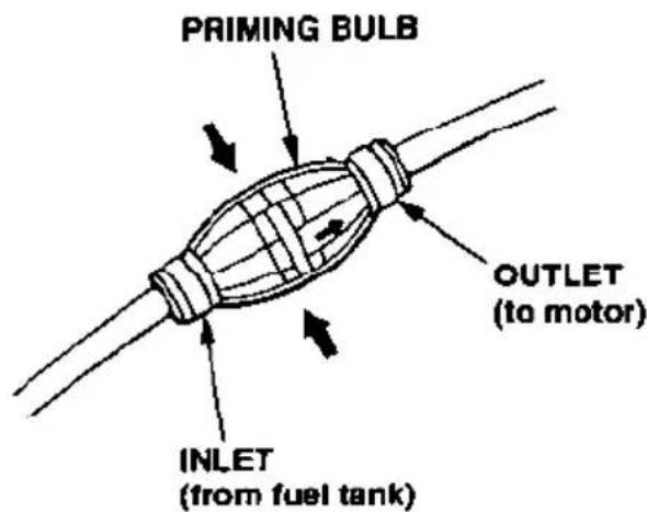
Hold the priming bulb with the outlet end higher than the inlet end. Squeeze the primer bulb several times, until it feels firm, indicating that fuel has reached the carburetor.
Check to be sure there are no fuel leaks before starting the engine.
Do not squeeze the priming bulb when the engine is running, because that could flood the carburetor.
natural_image
Diagram of a mechanical assembly with no visible text or symbolsFUEL HOSE CONNECTOR FOR FUEL TANK
STARTING THE ENGINE
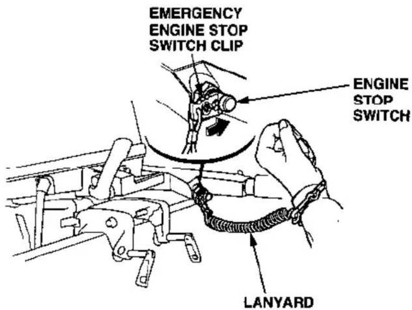
- Put the emergency engine stop switch clip in the engine stop switch, and attach the lanyard to your wrist.
The engine will not start or run, unless the clip is in the switch.
The emergency engine stop switch clip and lanyard system is a safety device that will stop the engine if you fall away from the controls while operating the boat.
Always attach the lanyard to your wrist before starting the engine.
- Check the position of the gear-shift lever. It must be in the N (neutral) position for starting.
If the gearshift lever is in the F (forward) or R (reverse) position, the recoil starter will not operate, and the electric starter button (applicable models) is blocked.
- Align the throttle grip START position with the mark on the tiller handle.
- To start a cold engine, pull out the choke knob. To restart a warm engine, leave the choke knob pushed in.
- Operate the starter.
USING THE RECOIL STARTER
Pull the recoil starter grip slowly until you feel resistance, then pull briskly.
NOTICE
- Do not allow the starter grip to snap back against the engine. Return it gently to prevent damage to the starter.
- Do not pull the starter grip while the engine is running, as that may damage the starter.
USING THE ELECTRIC STARTER (applicable models)
Press the starter button to operate the electric starter.
NOTICE
- Do not use the starter motor for more than 5 seconds. If the engine fails to start, release the starter button, and wait at least 10 seconds before operating the starter motor again.
- Do not press the electric starter button while the engine is running. This may damage the starter.
- After starting, check the oil pressure indicator light. The light should be on while the engine is running. If the light is off, stop the engine immediately, check the engine oil level, and inspect the engine for oil leaks.
If the engine fails to start, check the emergency stop switch clip.
If the oil level is OK, but the light stays off while the engine is running, take the motor to an authorized Honda marine dealer immediately.
- After starting, be sure water is flowing out of the water check hole.
NOTICE
If water does not flow out, or if steam comes out, stop the engine. check to see if the screen in the cooling water inlet is obstructed. Do not operate the engine until the problem has been corrected.
-
If the choke was used, push it in gradually as the engine warms up.
-
Before leaving the dock, check the operation of the emergency stop switch.
EMERGENCY STARTING
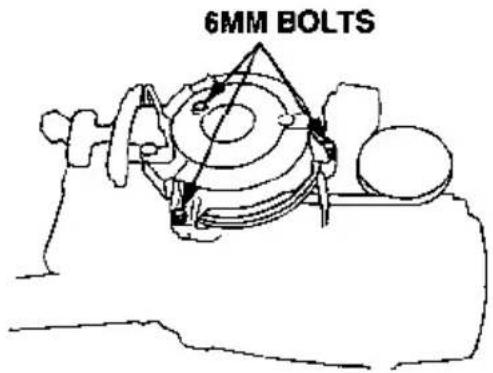
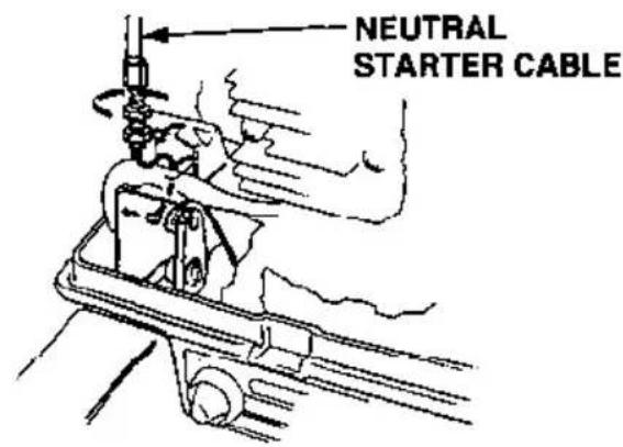
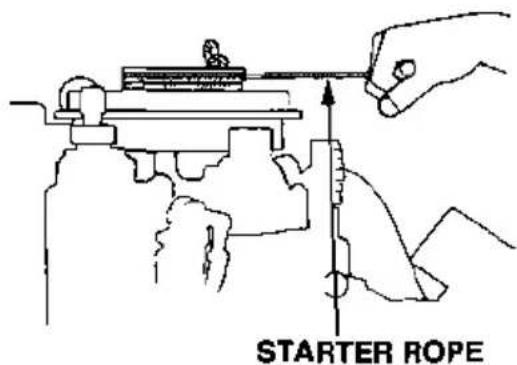
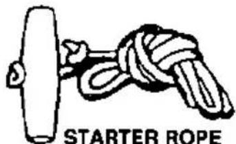
If the recoil starter is not working properly, the engine can be started with the spare starter rope in the tool kit.
- Remove the engine cover.
-
Remove the recoil starter by removing the three 6 mm bolts.
-
Disconnect the neutral starter cable.
-
Follow steps 1 through 4 of the normal engine starting procedure (p. 29 & 30).
-
Wind the spare rope clockwise around the pulley, and then pull it straight out to start the engine.
Keep clear of moving parts.
- Leave the recoil starter off and reinstall engine cover.
WARNING
Exposed moving parts can cause injury. Use extreme care when installing the engine cover. Do not operate the outboard motor without the engine cover.
STOPPING THE ENGINE
Emergency Engine Stopping
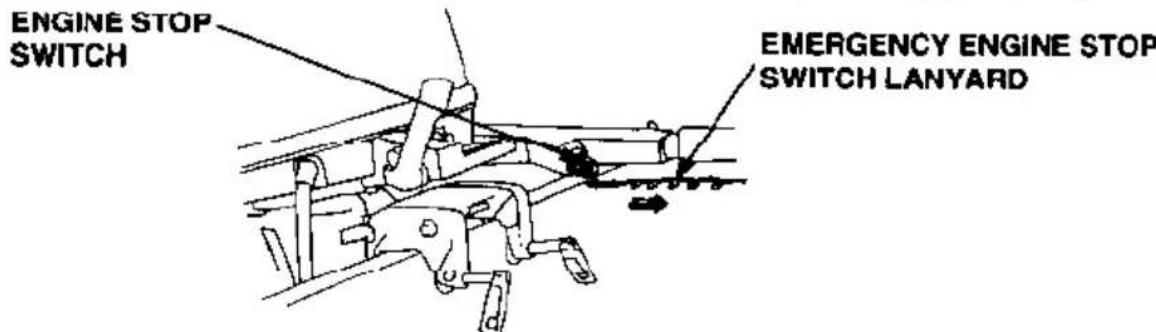
Disengage the emergency engine stop switch clip from the engine stop switch by pulling the lanyard.
It is a good idea to stop the engine with the emergency engine stop switch lanyard from time to time to be sure that the switch is operating properly.
Normal Engine Stopping
- Turn the throttle grip to the SLOW position, and move the gearshift lever to the N (neutral) position.
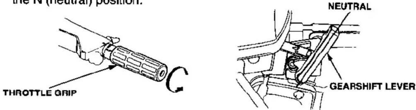
- Push the engine stop switch button until the engine stops.
- Remove the emergency engine stop switch lanyard and store it.
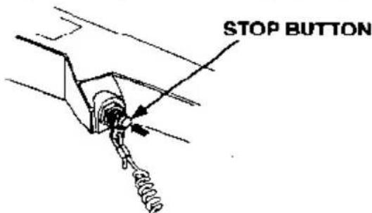
In the event that the engine does not stop when you push the engine stop switch, pull the emergency engine stop switch lanyard. If the engine continues to run, pull the choke knob to stop the engine.
GEAR SHIFTING
Put the tilt lever in the RUN position to prevent the outboard motor from tilting up when operating in reverse (refer to page 38).
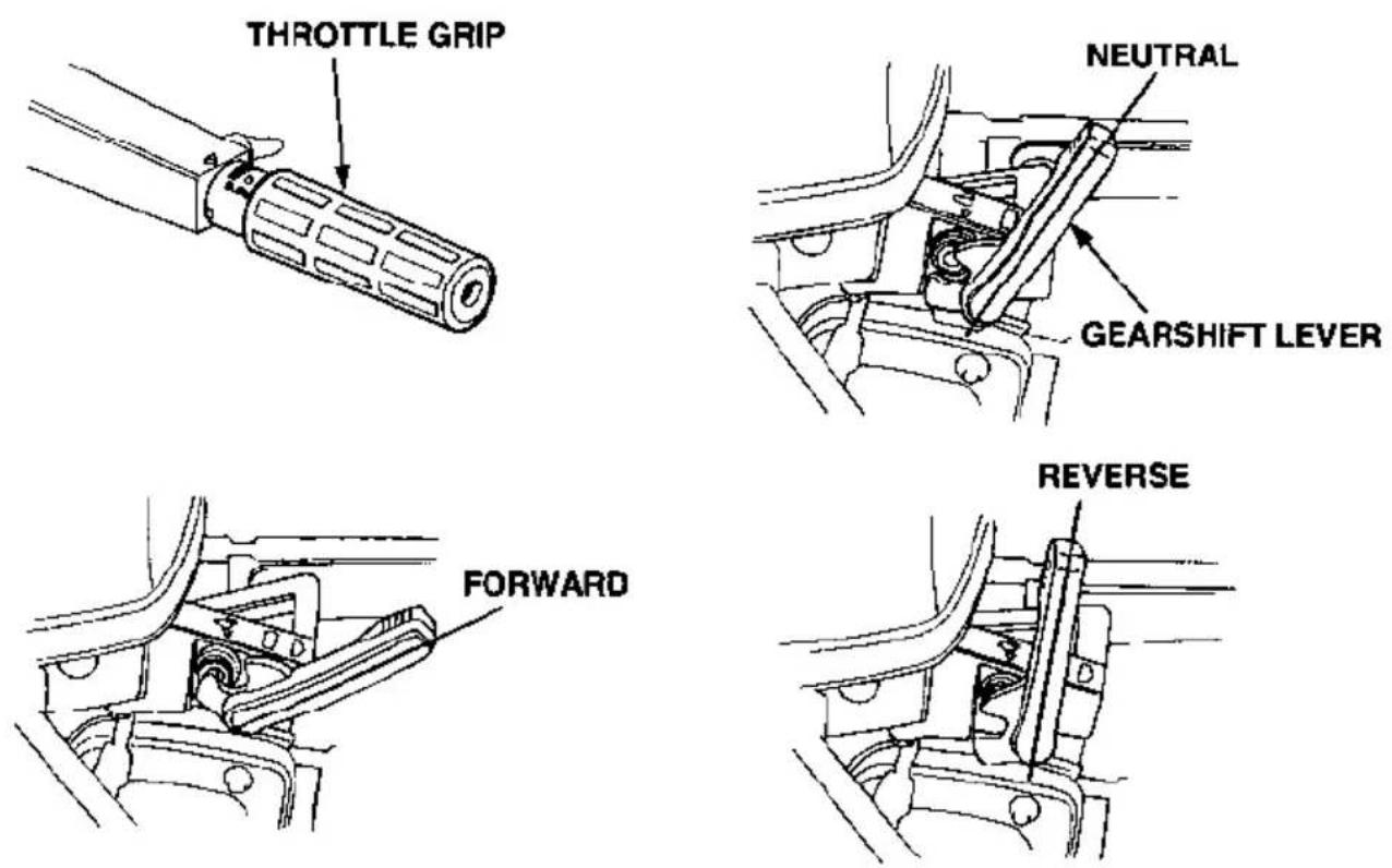
The gearshift lever has 3 positions: FORWARD, NEUTRAL, and REVERSE. An indicator at the base of the gearshift lever aligns with letters F, N, or R on the engine case to show the gear that has been selected.
Turn the throttle grip to SLOW to decrease engine speed before moving the gearshift lever.
NOTICE
When operating in reverse, proceed with caution to avoid hitting any underwater obstructions with the propeller.
The BF9.9A gear shift mechanism limits throttle opening in the N (neutral) position. The BF15A gear shift mechanism limits throttle opening in the N (neutral) and R (reverse) positions. Both outboard motors allow the throttle to be opened to FAST with the gear shift lever in the F (forward) position.
STEERING
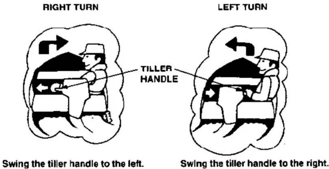
To turn to the right, swing the tiller handle to the left. To turn to the left, swing the tiller handle to the right.
Boats equipped with a remote control steering wheel are controlled in the same way as a car.
The steering friction should be adjusted so that stable boat operation is maintained with a minimum of operator effort.
CRUISING
With the gearshift lever in the forward position F, turn the throttle grip toward FAST to increase speed. For normal cruising, open the throttle about 3/4.
To hold the throttle at a steady setting, turn the throttle friction knob clockwise. To free the throttle grip for manual speed control, turn the friction knob counterclockwise.
This outboard motor is provided with an overrev limiter in order to prevent a breakdown due to excessive engine speed. If for example, the outboard motor is tilted excessively, or ventilation occurs during a sharp turn, the engine may overrev, activating the overrev limiter, causing engine speed to become unstable. If the engine speed becomes unstable when the outboard motor is run with the grip near the "fully open" position, return the grip to the "low speed" side until the speed becomes stable.
For best performance, passengers and equipment should be distributed evenly to balance the boat.
TILTING THE OUTBOARD MOTOR
Tilt the motor to prevent the propeller and gear case from hitting bottom when the boat is beached or stopped in shallow water.
- Stop the engine and put the gearshift lever into NEUTRAL.
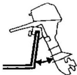
- Pull the tilt lever toward you, set the lever in the TILT position, and raise the engine to either the 30^ , 45^ or 70^ tilt position.
NOTICE
Do not use the throttle grip to tilt the outboard motor.
①
③
natural_image
Diagram of a mechanical device with a lever and adjustment arrows indicating motion (no text or symbols)70° (when mooring)
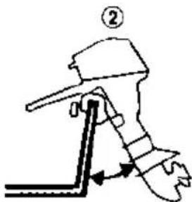
45°
natural_image
Diagram of a mechanical clamp or lever mechanism (no text or symbols present)30° (when cruising in shallow water)
- To return the engine to the normal RUN position, move the tilt lever away from you until it stops, tilt the engine up slightly, then lower the engine slowly.
NOTICE
- Make sure water comes out from the cooling water check hole.
- When the outboard motor is tilted, cruise at low speed.
- Never operate in reverse when the outboard motor is tilted, because the outboard motor will rise suddenly.
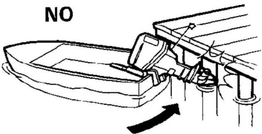
NOTICE
To avoid damaging the motor, be very careful when mooring a boat, especially when its motor is tilted up. Don't allow the motor to strike against the pier or other boats.
SERVICING YOUR HONDA OUTBOARD MOTOR
THE IMPORTANCE OF MAINTENANCE
Good maintenance is essential for safe, economical, and trouble-free operation. It will also help reduce air pollution.
WARNING
Improperly maintaining this outboard motor, or failure to correct a problem before operation, can cause a malfunction in which you can be seriously hurt or killed.
Always follow the inspection and maintenance recommendations and schedules in this owner's manual.
To help you properly care for your outboard motor, the following pages include a maintenance schedule, routine inspection procedures, and simple maintenance procedures using basic hand tools. Other service tasks that are more difficult, or require special tools, are best handled by professionals and are normally performed by a Honda technician or other qualified mechanic.
The maintenance schedule applies to normal operating conditions. If you operate your outboard motor under unusual conditions, consult an authorized Honda marine dealer for recommendations applicable to your individual needs and use.
Remember that your authorized Honda marine dealer knows your outboard motor best and is fully equipped to maintain and repair it.
To ensure the best quality and reliability, use only new, genuine Honda parts or their equivalents for repair and replacement.
Maintenance, replacement, or repair of emission control devices and systems may be performed by any engine repair establishment or individual, using parts that are “certified” to EPA standards.
MAINTENANCE SAFETY
Some of the most important safety precautions follow. However, we cannot warn you of every conceivable hazard that can arise in performing maintenance. Only you can decide whether or not you should perform a given task.
WARNING
Failure to properly follow maintenance instructions and precautions can cause you to be seriously hurt or killed.
Always follow the procedures and precautions in the owner's manual.
Safety Precautions
- Make sure the engine is off before you begin any maintenance or repairs. This will eliminate several potential hazards:
— Carbon monoxide poisoning from engine exhaust.
Be sure there is adequate ventilation whenever you operate the engine.
— Burns from hot parts.
Let the engine and exhaust system cool before touching.
— Injury from moving parts.
Do not run the engine unless instructed to do so.
- Read the instructions before you begin, and make sure you have the tools and skills required.
- To reduce the possibility of fire or explosion, be careful when working around gasoline. Use only a nonflammable solvent, not gasoline, to clean parts. Keep cigarettes, sparks, and flames away from all fuel-related parts.
TOOL KIT AND SPARE PARTS
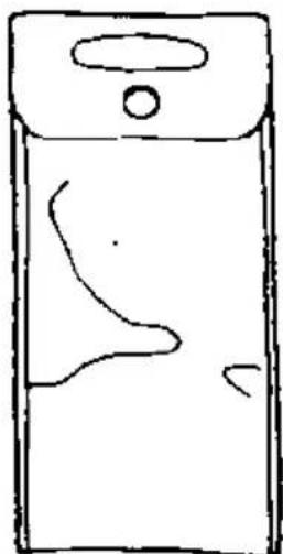
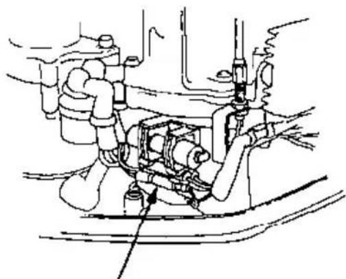
The following tools and spare parts are supplied with the outboard motor for maintenance, adjustment, and emergency repairs.
Tool Kit
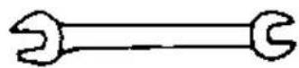
9 X 12 mm WRENCH

10 X 12 mm WRENCH
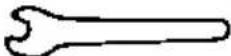
8 mm WRENCH

FLAT SCREWDRIVER

PHILIPS SCREWDRIVER

OIL CHECK SCREWDRIVER
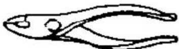
PLIERS

SCREWDRIVER HANDLE
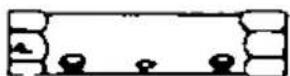
18 X 19 mm
SOCKET WRENCH
natural_image
Simple line drawing of a smartphone with a handle and screen (no text or symbols)TOOL BAG
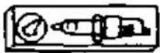
SPARE SPARK
PLUG
natural_image
Technical line drawing of a mechanical assembly with no visible text or symbolsSPARE FUSE (ELECTRIC STARTER MODEL ONLY)
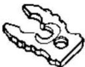
EMERGENCY STOP
SWITCH CLIP
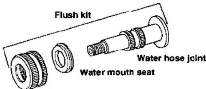
Water mouth nut
MAINTENANCE SCHEDULE
| REGULAR SERVICE PERIOD (3)ITEM Perform at every indicated month or operating hour interval, whichever comes first. | EACH USE | FIRST MONTH OR 20 HRS | EVERY 6 MONTHS OR 100 HRS | EVERY YEAR OR 200 HRS. | ||
| • | Engine oil | Check level | ○ | |||
| Change | ○ | ○ | ||||
| • | Gear case oil | Check level | ○ | |||
| Change | ○ | ○ | ||||
| Check for water contamination | ○ | |||||
| Starter rope | Check | ○ | ||||
| Carburetor linkage | Check | ○(2) | ○(2) | |||
| • | Valve clearance | Check-Readjust | ○(2) | ○(2) | ||
| • | Spark plug | Check-Clean | ○ | |||
| Propeller (cotter pin) | Check | ○ | ○ | |||
| Anode | Check | ○ | ||||
| Lubrication | Grease | ○(1) | ○(1) | |||
| Fuel tank | Clean | ○ | ||||
| Fuel filter | Replace | ○(2) | ||||
| • | Thermostat | Check | ○(2) | |||
| Fuel line | Check (Replace if necessary) | ○ | Every 2 years (2) | |||
- Emission-related items.
NOTE: (1) Lubricate more frequently when used in salt water.
(2) These items should be serviced by an authorized Honda marine dealer, unless the owner has the proper tools and is mechanically proficient. See the Honda Shop Manual.
(3) For professional commercial use, log hours of operation to determine proper maintenance intervals.
REFUELING
Fuel tank capacity
3.2 US gal (12.0 ℓ, 2.6 Imp gal)
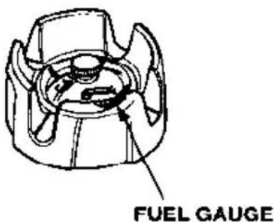
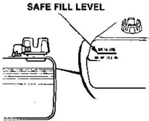
Check the fuel gauge and refill the tank to the SAFE FILL LEVER mark if necessary
⚠ WARNING
Gasoline is highly flammable and explosive.
You can be burned or seriously injured when handling fuel.
- Stop the engine and keep heat, sparks, and flame away.
- Handle fuel only outdoors.
- Wipe up spills immediately.
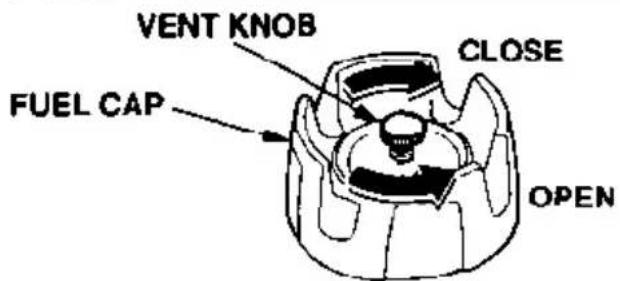
Remove the fuel tank from the boat for refilling. Turn the vent knob counterclockwise to the open position and remove the fuel cap.
Refuel in a well-ventilated area. Fill the fuel tank up to teh SAFE FILL LEVEL mark only. Inspect the condition of the fuel cap gasket and replace if necessary.
After refilling, install and tighten the fuel cap securely. turn the vent knob clockwise to the closed position. Return the fuel tank to the boat.
FUEL RECOMMENDATIONS
Use unleaded gasoline with a pump octane rating of 86 or higher.
These outboard motors are certified to operate on unleaded gasoline. Unleaded gasoline produces fewer engine and spark plug deposits and extends exhaust system life.
Never use stale or contaminated gasoline or an oil/gasoline mixture. Avoid getting dirt or water in the fuel tank.
Occasionally you may hear light "spark knock" or "pinging" (metallic rapping noise) while operating under heavy loads. This is no cause for concern.
If spark knock or pinging occurs at a steady engine speed, under normal load, change brands of gasoline. If spark knock or pinging persists, see an authorized Honda marine dealer.
NOTICE
Running the engine with persistent spark knock or pinging can cause engine damage.
Running the engine with persistent spark knock or pinging is misuse, and the Distributor's Limited Warranty does not cover parts damaged by misuse.
COOLING SYSTEM CLEANING AND FLUSHING
After each use in salt water or dirty water, thoroughly clean and flush the outboard motor.
WARNING
- For safety, the propeller must be removed.
- Be sure the outboard motor is securely mounted, and do not leave it unattended while running.
- Keep children and pets away from the area, and stay clear of moving parts during this procedure.
NOTICE
Running the engine without water can cause serious engine damage due to overheating. Be sure that water flows from the water check hole while the engine is running. If not, stop the engine and determine the cause of the problem.
Cleaning and Flushing With the Flush Kit
-
Wash the outside of the outboard motor with clean, fresh water.
-
Remove the flush bolt.
-
Flush the cooling system, using the water hose flush kit and a water hose.
a. Attach a hose from a fresh water faucet to the water hose connector of the flush kit.
b. Remove the propeller.
c. Turn on the fresh water supply to the hose.
d. Start the engine and run in neutral at idle for at least 10 minutes.
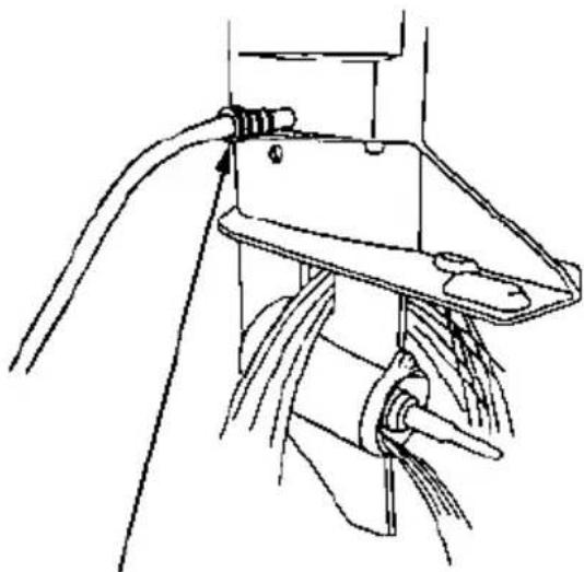
natural_image
Technical line drawing of a mechanical assembly with wires and components (no text or symbols)WATER HOSE CONNECTOR
Cleaning and Flushing Without the Flush Kit
-
Wash the outside of the outboard motor with clean, fresh water.
-
Remove the propeller.
-
Stand the motor in a suitable container of water. The water level must be at least 2 inches above the anticavitation plate.
-
Start the engine and run slowly for at least 10 minutes.
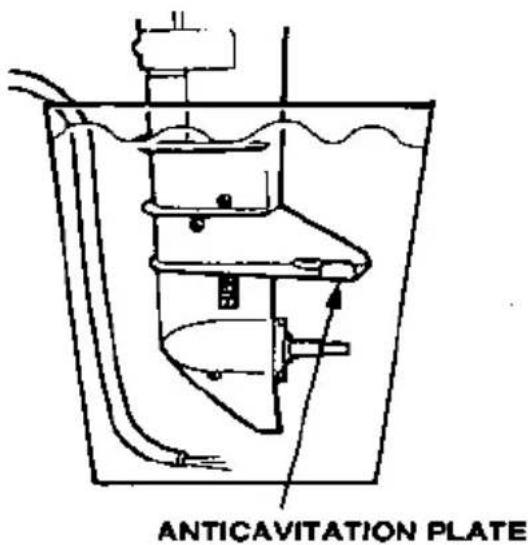
ENGINE OIL LEVEL CHECK
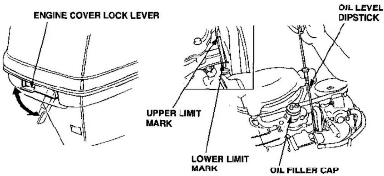
Check the engine oil level with the engine stopped and the outboard motor in a vertical position.
- Move the engine cover lock lever down to unlock the cover, and remove the cover.
- Remove the dipstick and wipe it clean.
- Insert the dipstick all the way in, then remove it and check the oil level shown on the dipstick.
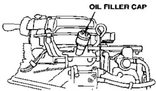
- If the oil level is low, remove the oil filler cap, and add oil to reach the upper limit mark shown on the dipstick. Use the oil recommended on page 49.
NOTICE
Running the engine with a low oil level can cause engine damage.
-
Install the oil filler cap and tighten it securely.
-
Install the engine cover, and lock it by moving the lever up.
ENGINE OIL CHANGE
Drain the used oil while the engine is warm. Warm oil drains quickly and completely.
-
Move the engine cover lock lever (page 47) down to unlock the cover, and remove the cover.
-
Place a suitable container below the engine oil drain location to catch the used oil, then remove the oil filler cap and the drain plug.
-
Allow the used oil to drain completely, then reinstall the drain plug, and tighten it securely.
NOTICE
Improper disposal of engine oil can be harmful to the environment. If you change your own oil, please dispose of the used oil properly. Put it in a sealed container, and take it to a recycling center. Do not discard it in a trash bin or dump it on the ground.
- With the outboard motor in a vertical position, fill to the upper limit mark on the dipstick (p. 47) with the recommended oil (p. 49).
Engine oil capacity: 1.2 US qt (1.1 ℓ, 1.0 Imp qt)
-
Install the oil filler cap and tighten it securely.
-
Install the engine cover, and lock it by moving the lever up.
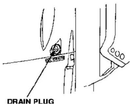
ENGINE OIL RECOMMENDATIONS
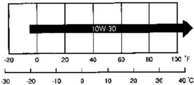
Oil is a major factor affecting performance and service life. Use 4-stroke automotive detergent oil.
SAE 10W-30 is recommended for general use.
SAE Viscosity Grades
line
| Temperature (°C) | Value | |---|---| | -20 | 10W-30 | | 0 | 10W-30 | | 20 | 10W-30 | | 40 | 10W-30 | | 60 | 10W-30 | | 80 | 10W-30 | | 100 | 10W-30 | | -30 | 10W-30 | | -20 | 10W-30 | | -10 | 10W-30 | | 0 | 10W-30 | | 10 | 10W-30 | | 20 | 10W-30 | | 30 | 10W-30 | | 40 | 10W-30 |AMBIENT TEMPERATURE
The SAE oil viscosity and service classification are in the API label on the oil container. Honda recommends that you use API SERVICE category SF or SG.
GEAR OIL LEVEL CHECK
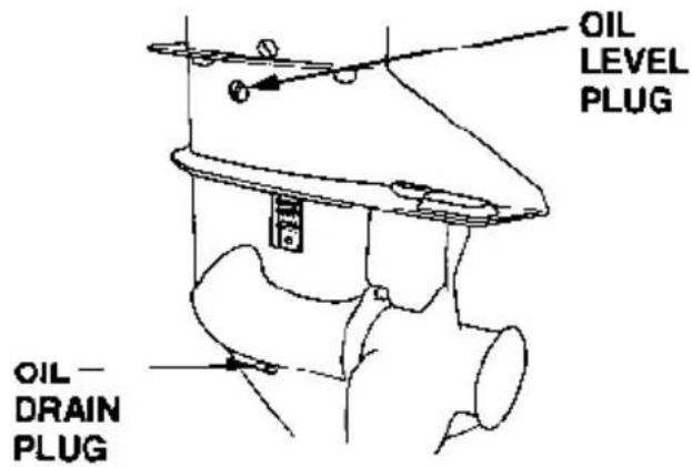
Check the oil level when the motor is in the vertical position. Remove the level plug and see if oil flows out.
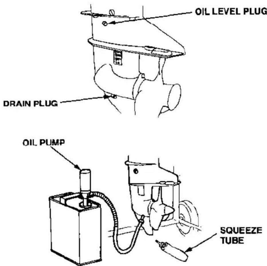
If no oil flows out, use a commercially available oil pump or squeeze tube to fill the gear case with the gear oil recommended on page 50. Pump or squeeze fresh oil through the OIL DRAIN plug hole until oil begins flowing out through the OIL LEVEL plug hole.
If there is water in the oil, the water will flow out first when the drain plug is removed, or the oil will be a milky color. If water is detected in the oil, the outboard motor should be inspected by an authorized Honda Outboard Motor dealer.
GEAR OIL CHANGE
Recommended oil : Marine SAE90 hypoid gear oil API Service Classification (GL-4 or GL-5)
Oil Capacity : 0.25 US qt (0.24 ℓ, 0.21 Imp qt)
Remove the level plug and drain plug and allow the gear oil to thoroughly drain into a suitable container.
Pump or squeeze the recommended gear oil through the OIL DRAIN plug hole until oil starts flowing out through the OIL LEVEL plug hole.
Use new sealing washers. Install the oil level plug first and then the oil drain plug. Tighten securely.
LUBRICATION
Apply marine anticorrosion grease to the following areas:
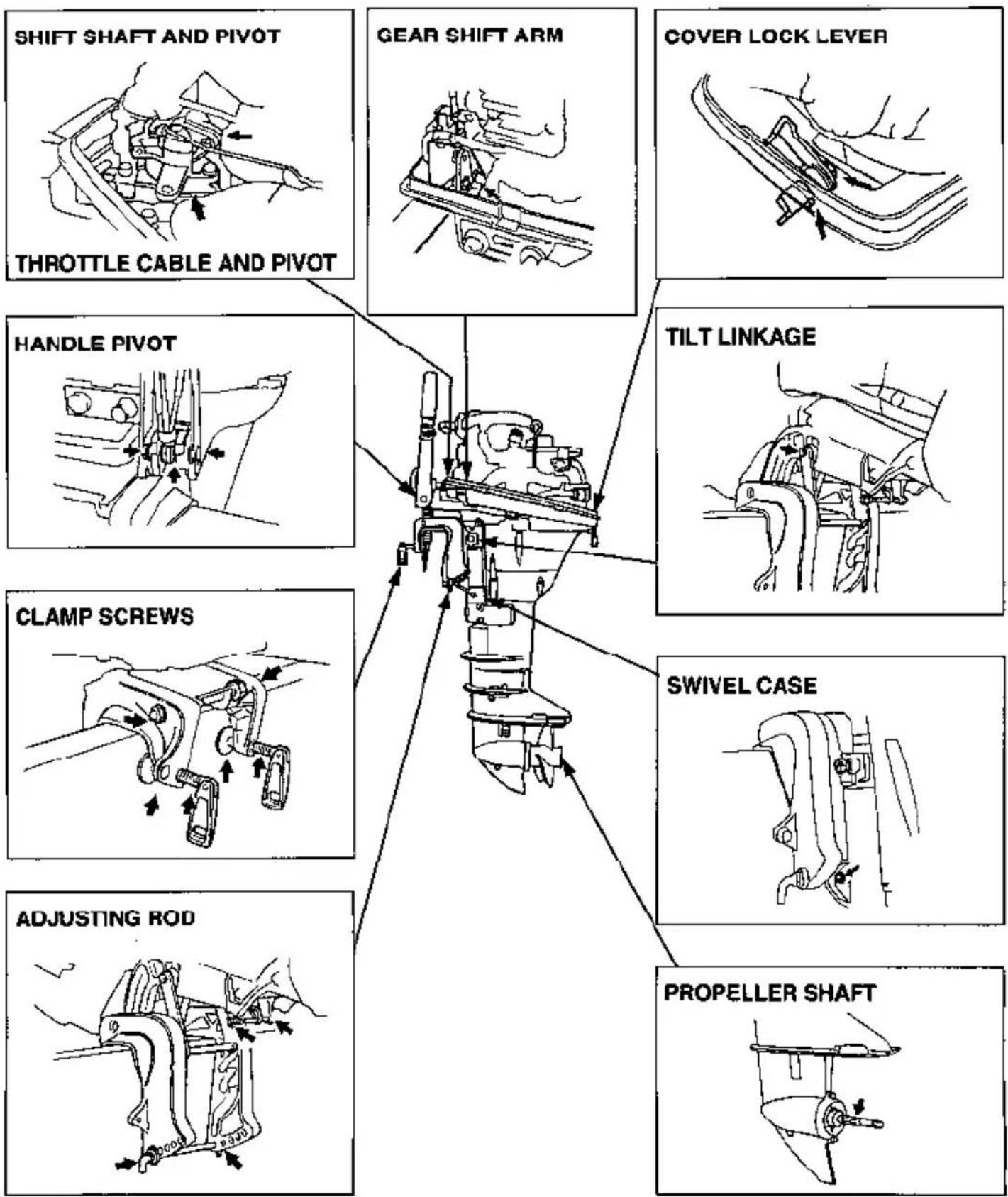
Apply anticorrosion oil to pivot surfaces where grease cannot penetrate.
SPARK PLUG SERVICE
Recommended spark plugs:
BF9.9A: DR-5HS (NGK), X16FSR-U (DENSO)
BF15A: DR-6HS (NGK), X20FSR-U (DENSO)
To ensure proper engine operation, the spark plugs must be properly gapped and free of deposits.
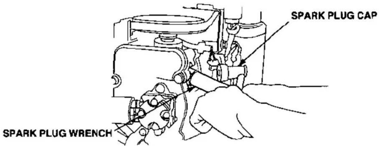
- Remove the engine cover.
- Remove the spark plug caps.
- Use the wrench supplied in the tool kit to remove the spark plugs.
-
Visually inspect the spark plugs. Discard the spark plugs if there is apparent wear, or if the insulators are cracked or chipped. Clean the spark plugs with a wire brush if they are to be reused.
-
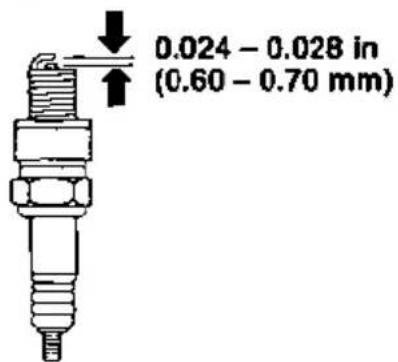
Measure the plug gaps with a feeler gauge.
Correct as necessary by carefully bending the side electrode.
The gaps should be:
0.024 - 0.028 in (0.60 - 0.70 mm)
-
Thread the plugs in by hand to prevent cross threading.
-
After the spark plugs are seated, tighten with a spark plug wrench to compress the washers.
If installing new spark plugs, tighten 1/2 turn after the spark plugs seat to compress the washers. If reinstalling used spark plugs, tighten 1/8–1/4 turn after the spark plugs seat to compress the washers.
NOTICE
- The spark plugs must be securely tightened. Improperly tightened plugs can become very hot and may cause engine damage.
- Use only the recommended spark plugs or equivalent. Spark plugs which have an improper heat range may cause engine damage.
FUEL FILTER REPLACEMENT
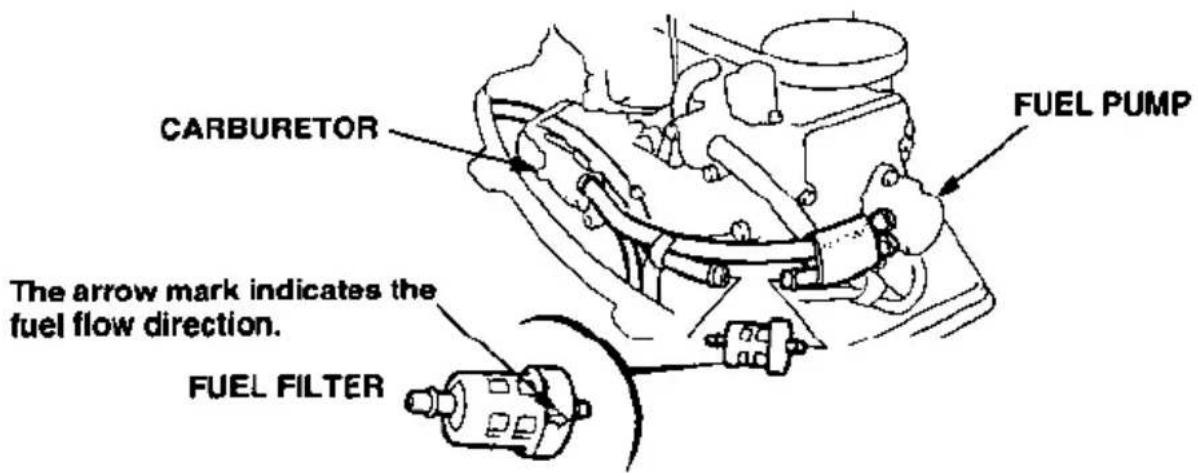
The fuel filter is located between the fuel coupling and the fuel pump. Water or sediment accumulated in the fuel filter can cause loss of power or hard starting. To prevent engine malfunction, replace the fuel filter regularly.
WARNING
Gasoline is highly flammable and explosive.
You can be burned or seriously injured when handling fuel.
- Keep heat, sparks and flame away.
- Handle fuel only outdoors.
-
Wipe up spills immediately.
-
Disconnect the fuel tank line from the motor.
- Remove the engine cover, and remove the fuel filter. Before removing the filter, place clamps on the fuel tubes on each side of the filter to prevent fuel leakage.
- Install the new fuel filter, so that the arrow on the fuel filter is on the fuel pump side. Fuel flow will be impeded if the filter is installed backward.
-
If loss of power or hard starting is found to be caused by excessive water or sediment accumulated in the fuel filter, inspect the fuel tank. Clean the fuel tank if necessary.
-
Remove the clamps used to close the fuel tubes. Connect the fuel tank line to the motor. Turn the fuel tank vent knob counterclockwise to the open position, pump the primer bulb, and check for leaks.
RECOIL STARTER ROPE INSPECTION
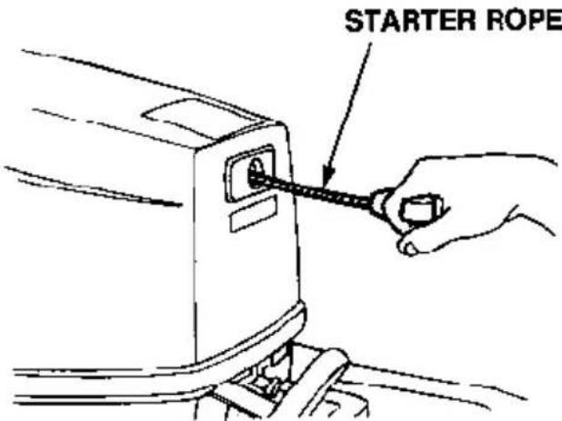
Inspect the recoil starter rope, and replace it if it becomes frayed.
Always keep the tool kit's emergency starter rope onboard in case the recoil starter rope fails.
ANODE REPLACEMENT
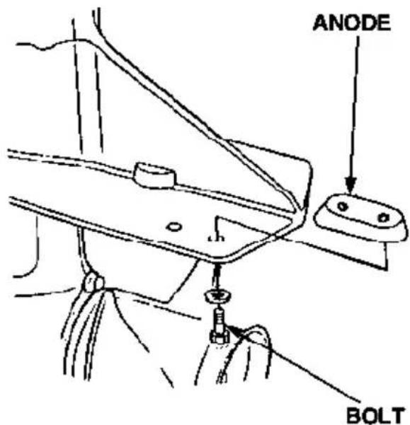
The anode is a sacrificial material which helps to protect the outboard motor from corrosion.
Replace the anode when it has been reduced to about half its original side, or if it is crumbling.
NOTICE
Painting or coating the anode will defeat its purpose and will lead to rust and corrosion damage to the outboard motor. The anode must be exposed to the water.
SERVICING YOUR HONDA OUTBOARD MOTOR
PROPELLER REPLACEMENT
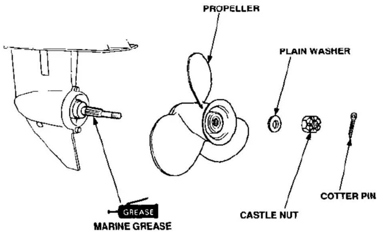
If the propeller is damaged by striking a rock, or other obstacle, replace the propeller as follows.
- Remove the cotter pin, then remove the 14 mm castle nut, plain washer, and the propeller.
- Install the new propeller in the reverse sequence to removal. Be sure to replace the cotter pin with a new one.
HELPFUL TIPS & SUGGESTIONS
STORING YOUR OUTBOARD MOTOR
Storage Preparation
Proper storage preparation is essential for keeping your pump troublefree and looking good. The following steps will help to keep rust and corrosion from impairing your outboard motor's function and appearance, and will make the engine easier to start when you use the outboard motor again.
Cleaning and Flushing
Wash the outside of the outboard motor with clean, fresh water, and flush the cooling system as described on page 46.
Disengage the emergency engine stop switch clip from the engine stop switch, and pull the recoil starter rope several times to expel any water remaining in the water pump.
Touch up any damaged paint, and coat areas that may rust with a light film of oil. Lubricate controls with a silicone spray lubricant.
Fuel
Gasoline will oxidize and deteriorate in storage. Old gasoline will cause hard starting, and it leaves gum deposits that clog the fuel system. If the gasoline in your fuel tank and carburetor deteriorates during storage, you may need to have the carburetor and other fuel system component serviced or replaced.
The length of time that gasoline can be left in your fuel tank and carburetor without causing functional problems will vary with such factors as gasoline blend, your storage temperatures, and whether the fuel tank is partially or completely filled. The air in a partially filled fuel tank promotes fuel deterioration. Very warm storage/temperatures accelerate fuel deterioration. Fuel deterioration problems may occur within a few months, or even less if the gasoline was not fresh when you filled the fuel tank.
The Distributor's Limited Warranty does not cover fuel system damage or engine performance problems resulting from neglected storage preparation.
-
Disconnect the fuel hose from the outboard motor.
-
With the outboard motor in a vertical position, place an approved gasoline container below the fuel drain outlet, and use a funnel to avoid spilling fuel. Loosen the drain screw to drain fuel from the carburetor.
WARNING
Gasoline is highly flammable and explosive.
You can be burned or seriously injured when handling fuel.
- Keep heat, sparks, and flame away.
- Handle fuel only outdoors.
- Wipe up spills immediately.
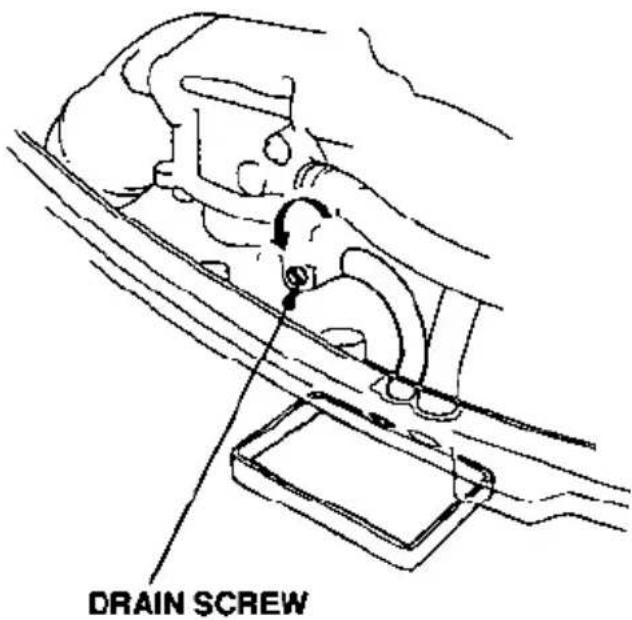
- After the fuel has drained from the carburetor, tighten the drain screw securely.
- Drain the fuel tank into an approved gasoline container, or if you need to store fuel in the portable fuel tank, you can extend fuel storage life by filling the fuel tank with fresh gasoline and adding a fuel stabilizer that is formulated for that purpose. Firmly close the fuel cap vent knob.
Engine Oil
- Change the engine oil (see page 48).
- Remove the spark plugs (see page 52)
- Pour a tablespoon (5 - 10 cc) of clean engine oil into each cylinder.
- Pull the starter rope several times to distribute the oil in the cylinders.
- Reinstall the spark plugs.
Storage Precautions
Select a well-ventilated storage area. If possible, avoid storage areas with high humidity.
If your portable fuel tank contains gasoline, store it away from any appliance that operates with a flame, such as a furnace, water heater, or clothes dryer. Also avoid any area with a spark-producing electric motor, or where power tools are operated.
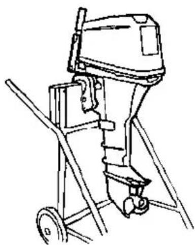
Store the outboard motor either vertically, or horizontally with the tiller handle side down, as shown.
If storing horizontally, be sure to fold the tiller handle, so the outboard motor rests on it's case protectors. Be sure all water has drained from the outboard motor before placing it on its side, so no residual water can enter the engine exhaust port.
NOTICE
Any other storage position may cause damage or oil leakage.
natural_image
Line drawing of a manual labor machine with wheels and handle (no text or symbols)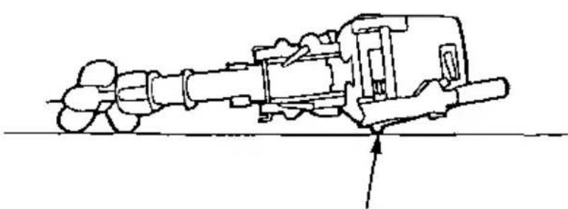
natural_image
Technical line drawing of a mechanical assembly with no visible text or symbolsCASE PROTECTORS
Cover the outboard motor to keep out dust. Do not use sheet plastic as a dust cover. A nonporous cover will trap moisture, promoting rust and corrosion.
Removal From Storage
Check your outboard motor as described in the BEFORE OPERATION chapter of this manual.
If the cylinder was coated with oil during storage preparation, the engine may smoke briefly at startup. This is normal.
TRANSPORTING
When trailering a boat with the outboard motor attached, leave the engine in the normal running position, if possible, and tighten the steering friction bolt securely (p. 36).
If there is insufficient road clearance in the normal running position, then tilt the outboard motor, leave the tilt lever in the tilt position, and use a motor support device, such as a transom-saver bar, or remove the outboard motor from the boat.
To transport the outboard motor when removed from the boat, secure it in either the vertical or horizontal position shown on page 59
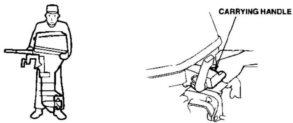
To carry, hold the outboard motor by the carrying handle, or hold by the carrying handle and the lug beneath engine cover lock lever as shown below.
NOTICE
Lifting the outboard motor by the engine cover, or using the installed outboard motor as a handle or lever to move the boat, can damage the outboard motor.
TAKING CARE OF UNEXPECTED PROBLEMS
ENGINE WILL NOT START
- Is the emergency stop switch clip in place?
- Is the gearshift lever in neutral?
- Is there fuel in the fuel tank?
- Is the fuel tank vent knob turned to open?
-
Is fuel reaching the carburetor?
-
Is the fuel system primed by squeezing the primer bulb?
Loosen the carburetor drain screw to see if there is fuel in the carburetor float bowl.
WARNING
If any fuel is spilled, make sure the area is dry before testing the spark plug or starting the engine. Spilled fuel or fuel vapor may ignite.
TAKING CARE OF UNEXPECTED PROBLEMS
- Are the spark plugs firing?
a. Remove and inspect the spark plugs. clean and dry the plugs, and check the electrode gaps (p. 52).
b. Install the spark plugs in their caps, and ground the side electrode to any engine ground away from the spark plug holes.
c. With recoil starter
Put the gearshift lever in the "NEUTRAL" position, pull the starter grip hard, and check to see whether or not a spark appears across the gap of the spark plug.
With electric starter (applicable models)
Put the gear lever in the "NEUTRAL" position, operate the starter motor, and check whether or not a spark appears across the gap of the spark plug.
If the spark plugs are OK, reinstall them, and try to start the engine.
If a spark does not appear, either replace the spark plugs or contact your authorized Honda marine motor dealer.
ENGINE OVERHEATS
- Is the water intake screen clogged?
- Is the thermostat faulty?
- Is the water level correct?
BATTERY DOES NOT CHARGE AND ELECTRIC STARTER (applicable models) DOES NOT OPERATE
The battery-charging circuit (all models) and the electric starter relay circuit (applicable models) are protected by a 15-ampere fuse.
If the fuse burns out, running the engine will not charge the battery (all models), and the electric starter (applicable models) will not operate.
Fuse Replacement
- With the engine stopped, remove the engine cover.
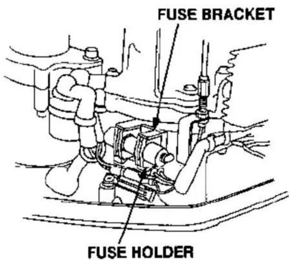
- Remove the fuse holder from the fuse bracket. Pull the rubber cover off the end of the fuse holder, and unscrew the fuse holder cap.
- Remove and inspect the fuse. If the fuse is burnt out, Install a replacement 15 A fuse. The outboard motor is supplied with a spare 15 A fuse, which is located below the fuse holder.
NOTICE
Never use a fuse with a rating greater than 15 amperes. Serious damage to the electrical system could result.
- Reinstall the fuse holder and engine cover.
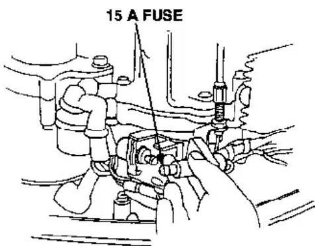
Before further operation, try to determine and correct the electrical problem that caused the fuse to burn out. An uncorrected electrical problem may cause the fuse to burn out again.
SUBMERGED MOTOR
A submerged motor must be serviced immediately after it is recovered from the water in order to minimize corrosion.
If there is a Honda marine dealership nearby, take the motor immediately to the dealer. If you are far from a dealership, proceed as follows:
-
Remove the engine cover, and rinse the motor with fresh water to remove salt water, sand, mud, etc.
-
Loosen the carburetor drain screw (p. 58), drain the contents of the carburetor into a suitable container, then tighten the drain screw.
-
Change the engine oil (p. 48). If there was water in the engine crankcase, or the used engine oil showed signs of water contamination, then a second engine oil change should be performed after running the engine for 1/2 hour.
-
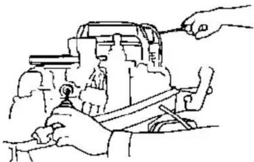
Remove the spark plugs. Disengage the emergency engine stop switch clip from the engine stop switch and pull the recoil starter several times to completely expel water from the cylinders.
natural_image
Line drawing of hands operating a mechanical device with tools (no text or symbols)NOTICE
- When cranking the engine with an open ignition circuit (spark plugs removed from the ignition circuit), disengage the emergency engine stop switch clip from the engine stop switch to prevent electrical damage to the ignition system.
-
If the engine was running when it submerged, there may be mechanical damage, such as bent connecting rods. If the engine binds when cranked, do not attempt to run the engine until it has been repaired.
-
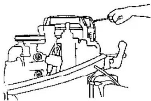
Pour a teaspoon of engine oil into each spark plug hole, then pull the recoil starter several times to lubricate the inside of the cylinders. Reinstall the spark plugs and engage the emergency engine stop switch clip with the engine stop switch.
-
Attempt to start the engine.
-
If the engine fails to start, remove the spark plugs, clean and dry the electrodes, then reinstall the spark plugs and attempt to start the engine again.
-
If the engine statrs, and no mechanical damage is evident, continue to run the engine for 1/2 hour or longer (be sure the water level is at least 2 inches above the anticavitation plate).
-
As soon as possible, take the motor to a Honda marine dealer for inspection and service.
natural_image
Line drawing of a mechanical assembly with a hand adjusting parts (no text or symbols)TECHNICAL & CONSUMER INFORMATION
TECHNICAL INFORMATION
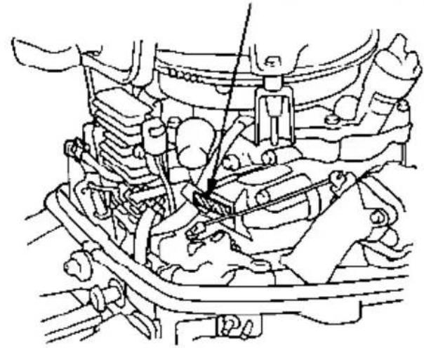
Serial Number Locations
ENGINE SERIAL NUMBER
natural_image
Technical line drawing of an engine cylinder assembly (no text or labels)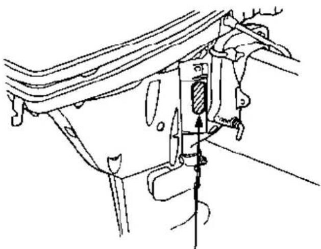
natural_image
Technical line drawing of a mechanical assembly with no visible text or symbolsFRAME SERIAL NUMBER
Record the engine and frame serial numbers in the space below. You will need these serial numbers when ordering parts, and when making technical or warranty inquiries (see page 77).
Engine serial number: ____
Frame serial number:
Carburetor Modification for High Altitude Operation
At high altitude, the standard carburetor air-fuel mixture will be too rich. Performance will decrease, and fuel consumption will increase. A very rich mixture will also foul the spark plug and cause hard starting.
High altitude performance can be improved by specific modifications to the carburetor. If you always operate your engine at altitudes above 5,000 feet (1,500 meters), have an authorized Honda marine dealer perform this carburetor modification.
Even with carburetor modification, engine horsepower will decrease about 3.5% for each 1,000-foot (300-meter) increase in altitude. The effect of altitude on horsepower will be greater than this if no carburetor modification is made.
NOTICE
When the carburetor has been modified for high altitude operation, the air-fuel mixture will be too lean for low altitude use. Operation at altitudes below 5,000 feet (1,500 meters) with a modified carburetor may cause the engine to overheat and result in serious engine damage. For use at low altitudes, have an authorized Honda marine dealer return the carburetor to original factory specifications.
TECHNICAL & CONSUMER INFORMATION
Oxygenated Fuels
Some conventional gasolines are being blended with alcohol or an ether compound. These gasolines are collectively referred to as oxygenated fuels. To meet clean air standards, some areas of the United States and Canada use oxygenated fuels to help reduce emissions.
If you use an oxygenated fuel, be sure it is unleaded and meets the minimum octane rating requirement.
Before using an oxygenated fuel, try to confirm the fuel's contents. Some states/provinces require this information to be posted on the pump.
The following are the EPA-approved percentages of oxygenates:
ETHANOL
(ethyl or grain alcohol) 10% by volume
You may use gasoline containing up to 10% ethanol by volume. Gasoline containing ethanol may be marketed under the name "Gasohol".
MTBE
(Methyl Tertiary Butyl Ether) 15% by volume
You may use gasoline containing up to 15% MTBE by volume.
METHANOL
(methyl or wood alcohol) 5% by volume
You may use gasoline containing up to 5% methanol by volume, as long as it also contains cosolvents and corrosion inhibitors to protect the fuel system. Gasoline containing more than 5% methanol by volume may cause starting and/or performance problems. It may also damage metal, rubber, and plastic parts of your fuel system.
If you notice any undesirable operating symptoms, try another service station, or switch to another brand of gasoline.
Fuel system damage or performance problems resulting from the use of an oxygenated fuel containing more than the percentages of oxygenates mentioned above are not covered under warranty.
Emission Control System Information
Source of Emissions
The combustion process produces carbon monoxide, oxides of nitrogen, and hydrocarbons. Control of hydrocarbons and oxides of nitrogen is very important because, under certain conditions, they react to form photochemical smog when subjected to sunlight. Carbon monoxide does not react in the same way, but it is toxic.
Honda utilizes lean carburetor settings and other systems to reduce the emissions of oxides of nitrogen, and hydrocarbons.
The U.S. Clean Air Act
EPA regulations require all manufacturers to furnish written instructions describing the operation and maintenance of emission control systems.
The following instructions and procedures must be followed in order to keep the emissions from your Honda engine within the emission standards.
Tampering and Altering
Tampering with or altering the emission control system may increase emissions beyond the legal limit. Among those acts that constitute tampering are:
- Removal or alteration of any part of the intake, fuel, or exhaust systems.
- Altering or defeating the governor linkage or speed-adjusting mechanism to cause the engine to operate outside its design parameters.
Problems That May Affect Emissions
If you are aware of any of the following symptoms, have your engine inspected and repaired by your servicing dealer.
• Hard starting or stalling after starting.
- Rough idle.
- Misfiring or backfiring under load.
• Afterburning (backfiring).
- Black exhaust smoke or high fuel consumption.
Replacement Parts
The emission control systems on your Honda engine were designed, built, and certified to conform with EPA emission regulations. We recommend the use of genuine Honda parts whenever you have maintenance done. These original-design replacement parts are manufactured to the same standards as the original parts, so you can be confident of their performance. The use of replacement parts that are not of the original design and quality may impair the effectiveness of your emission control system.
A manufacturer of an aftermarket part assumes the responsibility that the part will not adversely affect emission performance. The manufacturer or rebuilder of the part must certify that use of the part will not result in a failure of the engine to comply with emission regulations.
Maintenance
Follow the maintenance schedule on page 26. Remember that this schedule is based on the assumption that your machine will be used for its designed purpose. Sustained high-load or high-temperature operation, will require more frequent service.
Specifications
| Model | BF9.9A | |||
| Description code | BABS | |||
| Rated power | 7.4 kW (9.9 HP) | |||
| Full throttle range | 4,500 — 5,500 rpm | |||
| Engine type | 4-stroke OHC in-line twin cylinder | |||
| Displacement | 17.1 cu in (280 cm3) | |||
| Spark plug gap | 0.024 — 0.028 in (0.60 — 0.70 mm) | |||
| Starter system | With recoil starter (without electric starter) | |||
| Recoil starter & electric starter (with electric starter) | ||||
| Ignition system | C.D.. | |||
| Lubrication system | Trochoid pump pressure lubrication | |||
| Specified oil | Engine: API standard (SF or SG) SAE 10W-30Gear case: Marine SAE 90 hypoid gear oilAPI Service Classification (GL-4 or GL-5) | |||
| Oil capacity | Engine: 1.2 US qt, (1.1 ℓ, 1.0 Imp qt)Gear case: 0.25 US qt, (0.24 ℓ, 0.21 Imp qt) | |||
| D.C. output | 12V — 6A/6,000min-1(rpm) | |||
| Cooling system | Water cooling with thermostat (volumetric pump) | |||
| Exhaust system | Underwater exhaust | |||
| Spark plug | DR-5HS (NGK), X16FSR-U (DENSO) | |||
| Fuel pump | Diaphragm type fuel pump | |||
| Fuel | Automotive gasoline (86 pump octane) | |||
| Tank capacity | 3.2 US gal (12.0 ℓ, 2.6 Imp gal) | |||
| Steering equipment | Tiller handle | |||
| Tilt angle | 3-stage adjustment (30°, 45° and 70°) | |||
| Angle of rotation | 40° (both sides) | |||
| Dimensions | Length | S Model21.7 in (550 mm) | L Model21.7 in (550 mm) | X Model21.7 in (550 mm) |
| Height | 41.3 in (1,050 mm) | 46.5 in (1,180 mm) | 52.0 in (1,320 mm) | |
| Width | 12.6 in (320 mm) | 12.6 in (320 mm) | 12.6 in (320 mm) | |
| Outboard motor transom height | 17.3 in (440 mm) | 22.4 in (570 mm) | 28.0 in (710 mm) | |
| Standard propeller(No. of blades-diameter x pitch) | S Model9-1/2 x 9-1/2 in (3-240 x 240 mm)L, X Model9 1/2 x 8 5/8 in (3 240 x 220 mm) | |||
| Gear change | Forward-Neutral Reverse (dog type) | |||
| Dry weightwithout electric starter | S Model93.7 lbs (42.5 kg) | L Model95.9 lbs (43.5 kg) | X Model102.5 lbs (46.5 kg) | |
Honda outboards are power rated in accordance with NMMA procedures and using the ICOMIA standard 28/23.
| Model | BF15A | |||
| Description code | BAAS | |||
| Rated power | 11.2 kW (15 HP) | |||
| Full throttle range | 5,000 — 6,200 rpm | |||
| Engine type | 4-stroke OHC in-line twin cylinder | |||
| Displacement | 17.1 cu-in (280 cm3) | |||
| Spark plug gap | 0.024 — 0.028 in (0.60 — 0.70 mm) | |||
| Starter system | With recoil starter (without electric starter) | |||
| Recoil starter & electric starter (with electric starter) | ||||
| Ignition system | C.D.I. | |||
| Lubrication system | Trochoid pump pressure lubrication | |||
| Specified oil | Engine: API standard (SF or SG) SAE 10W-30Gear case: Marine SAE 90 hypoid gear oilAPI Service Classification (GL-4 or GL-5) | |||
| Oil capacity | Engine: 1.2 US qt, (1.1 ℓ, 1.0 lmp qt)Gear case: 0.25 US qt, (0.24 ℓ, 0.21 lmp qt) | |||
| D.C. output | 12V — 6A/6,000min-1(rpm) | |||
| Cooling system | Water cooling with thermostat (volumetric pump) | |||
| Exhaust system | Underwater exhaust | |||
| Spark plug | DR-6HS (NGK), X20FSR-U (DENSO) | |||
| Fuel pump | Diaphragm type fuel pump | |||
| Fuel | Automotive gasoline (86 pump octane) | |||
| Tank capacity | 3.2 US gal (12.0 ℓ, 2.6 lmp gal) | |||
| Steering equipment | Tiller handle | |||
| Tilt angle | 3-stage adjustment (30°, 45° and 70°) | |||
| Angle of rotation | 40° (both sides) | |||
| Dimensions | Length | S Model21.7 in (550 mm) | L Model21.7 in (550 mm) | X Model21.7 in (550 mm) |
| Height | 41.3 in (1,050 mm) | 46.5 in (1,180 mm) | 52.0 in (1,320 mm) | |
| Width | 12.6 in (320 mm) | 12.6 in (320 mm) | 12.6 in (320 mm) | |
| Outboard motor transom height | 17.3 in (440 mm) | 22.4 in (570 mm) | 28.0 in (710 mm) | |
| Standard propeller(No. of blades-diameter x pitch) | S Model9-1/2 x 9-1/2 in (3-240 x 240 mm)L, X Model9-1/2 x 8-5/8 in (3-240 x 220 mm) | |||
| Gear change | Forward-Neutral Reverse (dog type) | |||
| Dry weightwithout electric starter | S Model93.7 lbs (42.5 kg) | L Model95.9 lbs (43.5 kg) | X Model— | |
Honda outboards are power rated in accordance with NMMA procedures and using the ICOMIA standard 28/23.
BF9.9A & BF15A Tuneup
| Spark plug gap | 0.024-0.028 in (0.60-0.70 mm) | See page 52. |
| Idle speed | 1,100 ± 50 rpm | See shop manual. |
| Valve clearance (cold) | Intake: 0.12 + 0.02 mmExhaust: 0.15 ± 0.02 mm | See shop manual. |
| Other specifications | No other adjustments needed. | |
WIRING DIAGRAMS
TECHNICAL & CONSUMER INFORMATION
Models equipped with an Electric Starer
TECHNICAL & CONSUMER INFORMATION
TECHNICAL & CONSUMER INFORMATION
CONSUMER INFORMATION
Honda Publications
These publications will give you additional information for maintaining and repairing your outboard motor. You may order them from your Honda outboard motor dealer.
Shop Manual
This manual covers complete maintenance and overhaul procedures. It is intended to be used by a skilled technician.
Parts Catalog
This manual provides complete, illustrated parts lists.
Warranty Service Information
Honda marine dealership personnel are trained professionals. They should be able to answer any question you may have. If you encounter a problem that your dealer does not solve to your satisfaction, please discuss it with the dealership's management. The Service Manager or General Manager can help. Almost all problems are solved in this way.
If you are dissatisfied with the decision made by the dealership's management, contact the Honda Marine Customer Relations Office. You can write:
American Honda Motor Co., Inc.
Marine Division
Customer Relations Office
4900 Marconi Drive
Alpharetta, Georgia 30005-8847
Or telephone: (770) 497-6400
When you write or call, please give us this information:
• Model and serial number (see page 66)
• Name of the dealer who sold the outboard motor to you
• Name and address of the dealer who services your outboard motors
- Date of purchase
- Your name, address, and telephone number
• A detailed description of the problem
INDEX
A
Anode 18
ANODE REPLACEMENT 55
B
BATTERY CONNECTIONS 22
BEFORE OPERATION 25
ARE YOU READY TO GET UNDER WAY? 25
Knowledge 25
Safety Apparel 25
IS YOUR OUTBOARD MOTOR READY TO GO? 25
Maintenance Inspection 26
Safety Inspection 26
BREAK-IN PROCEDURE 27
C
Choke Knob 12
CONTENTS 3
CONTROLS & FEATURES....10
COMPONENT & CONTROL LOCATIONS 10
CONTROLS 12
Choke Knob 12
Electric Starter Button 14
Engine Cover Lock Lever 16
Engine Stop Switch....12
Fuel Cap Vent Knob 17
Fuel Priming Bulb 17
Gear Shift Lever....14
Recoil Starter Grip 14
Steering Friction Bolt 15
Throttle Friction Knob 13
Throttle Grip 13
Tilt Lever 15
Transom Angle Adjusting Rod 16
FEATURES 17
Anode 18
Fuel Gauge 17
Oil Pressure Indicator Light 17
Overrev Limiter 18
Water Check Hole 17
CRUISING 37
Carbon Monoxide Hazard 8
E
Electric Starter Button 14
Emergency Engine Stopping 34
EMERGENCY STARTING 33
Emission Control System Information 69
Engine Cover Lock Lever 16
ENGINE OIL CHANGE 48
ENGINE OIL LEVEL CHECK 47
ENGINE OIL RECOMMENDATIONS 49
ENGINE WILL NOT START 61
Engine Stop Switch 12
F
FEATURES 17
Anode 18
Fuel Gauge 17
Oil Pressure Indicator Light 17
Overrev Limiter....18
Water Check Hole 17
FUEL FILTER REPLACEMENT 53
FUEL RECOMMENDATIONS 45
Fuel Cap Vent Knob 17
Fuel Gauge 17
Fuel Hose Connections 28
Fuel Priming 28
Fuel Priming Bulb....17
Fuel Tank Placement 27
G
GEAR OIL CHANGE 50
GEAR OIL LEVEL CHECK 49
GEAR SHIFTING 35
Gearshift Lever 14
H
HELPFUL TIPS AND SUGGESTIONS 57
STORING YOUR OUTBOARD MOTOR....57
Removal From Storage 60
Storage Precautions 59
Storage Preparation....57
Honda Publications 76
1
INTRODUCTION....1
IMPORTANT SAFETY INFORMATION....7
INSTALLATION....19
BATTERY CONNECTIONS 22
INSTALLATION HEIGHT 19
INSTALLATION POSITION 19
MOTOR ANGLE ADJUSTMENT 21
MOTOR ANGLE FOR CRUISING 21
OUTBOARD MOTOR ATTACHMENT 20
L
LUBRICATION 51
M
Maintenance Inspection 26
MAINTENANCE SAFETY 41
Safety Precautions 41
MAINTENANCE SCHEDULE 43
MOTOR ANGLE ADJUSTMENT 21
MOTOR ANGLE FOR CRUISING 21
N
Normal Engine Stopping 34
0
Oil Pressure Indicator Light 17
OPERATION 27
BREAK-IN PROCEDURE 27
CRUISING 37
EMERGENCY STARTING 33
GEAR SHIFTING 35
PORTABLE FUEL TANK PLACEMENT AND CONNECTIONS 27
Fuel Hose Connections 28
Fuel Priming 28
Fuel Tank Placement 27
SAFE OPERATING PRECAUTIONS 27
STARTING THE ENGINE 29
STEERING 36
STOPPING THE ENGINE....34
Emergency Engine Stopping 34
Normal Engine Stopping 34
TILTING THE OUTBOARD MOTOR 38
OUTBOARD MOTOR ATTACHMENT 20
Overrev Limiter 18
Oxygenated Fuels 68
P
PORTABLE FUEL TANK 27
Fuel Hose Connections 28
Fuel Priming 28
Fuel Tank Placement 27
PROPELLER REPLACEMENT 56
Q
QUICK REFERENCE INFORMATION ____ Inside back cover
R
Recoil Starter Grip 14
RECOIL STARTER ROPE INSPECTION 55
REFUELING 44
Removal From Storage 60
\$
SAFE OPERATING PRECAUTIONS....27
SAFETY, A FEW WORDS ABOUT 2
Safety Inspection....26
SAFETY, OUTBOARD MOTOR 7
IMPORTANT SAFETY INFORMATION ....7
Carbon Monoxide Hazard 8
Operator Responsibility 7
Refuel With Care 8
SAFETY LABEL LOCATIONS 9
SPARK PLUG SERVICE 52
STARTING THE ENGINE 29
STEERING 36
STOPPING THE ENGINE....34
STORING YOUR OUTBOARD MOTOR....57
Serial Number Locations 66
Specifications 71
Steering Friction Bolt 15
Storage Precautions 59
Storage Preparation 57
SUBMERGED MOTOR 64
T
TAKING CARE OF UNEXPECTED PROBLEMS 61
TECHNICAL & CONSUMER INFORMATION 66
TECHNICAL INFORMATION....66
THE IMPORTANCE OF MAINTENANCE 40
Throttle Friction Knob 13
Throttle Grip 13
TILTING THE OUTBOARD MOTOR 38
Tilt Lever 15
TOOL KIT AND SPARE PARTS 42
TRANSPORTING....60
Transom Angle Adjusting Rod 16
W
Warranty Service Information....77
Water Check Tube 17
WIRING DIAGRAMS 74
MEMO
MEMO
MEMO
QUICK REFERENCE INFORMATION
| Fuel | Type | Unleaded gasoline with a pump octane rating of 86 or higher(page 45) |
| Capacity | 3.2 US gal (12.0 ℓ) | |
| Engine Oil | Type | SAE 10W-30, API SF or SG, for general use (page 49) |
| Capacity | 1.2 US qt (1.1 ℓ) | |
| Gear Oil | Type | Marine SAE 90 hypoid, API GL-4 or GL-5 |
| Capacity | 0.25 US qt (0.24 ℓ) | |
| Spark Plug | Type | BF9.9A: DR-5HS (NGK), X16FSR-U (DENSO)BF15A: DR-6HS (NGK), X20FSR-U (DENSO) |
| Gap | 0.024 - 0.028 in (0.60 - 0.70 mm)(page 52) | |
| Carburetor | Idle speed | 1,100 ± 50 rpm |
| Maintenance | Before each use | Check engine oil level(page 47).Check fuel hose(page 28).Check propeller and cotter pin(page 56).Check anode(page 55) |
| First 20 hours | Change engine oil(page 48).Change gear oil(page 50).Check carburetor linkage.Check/adjust valve clearance.Grease lubrication points(page 51). | |
| Subsequent | Refer to the maintenance schedule on page 43. |
Owner's Manual
Outboard Motor BF9.9A/15A
REMOTE CONTROL
Thank you for purchasing a Honda Outboard Motor.
This owner's manual supplement covers specific information about the Honda remote control equipped BF9.9A and BF15A outboard motors. Refer to the BF9.9A/15A owner's manual for all other information.
The owner's manual and this supplement contain information on how to operate your new outboard motor safely. Please read them carefully.
Keep the owner's manual and this supplement handy, so you can refer to them at any time, and be sure they accompany the outboard motor if you sell it.
We recommend that you read the warranty policy to fully understand your rights and responsibilities. The warranty policy is a separate document provided by your dealer.
The information in this publication was in effect at the time of approval for printing. American Honda Motor Co., Inc. reserves the right to discontinue or change specifications or design at any time without notice and without incurring any obligation whatever. No part of this publication may be reproduced without written permission.
1. SAFETY
- COMPONENT IDENTIFICATION 3
- INSTALLATION (see remote control installation instructions)
- PRE-OPERATION CHECKS . 4
- STARTING THE ENGINE 5
- OPERATION 17
- STOPPING THE ENGINE 18
- MAINTENANCE
- TRANSPORTING/STORAGE
- TROUBLESHOOTING
- SPECIFICATIONS
- WIRING DIAGRAM 19
- OPTIONAL PARTS 20
- WARRANTY SERVICE
The HIGHLIGHTED sections required no changes from the BF9.9A/15A owner's manual. These sections are not covered in this supplement.
The NON-HIGHLIGHTED sections contain only new information about a Remote Control Equipped BF9.9A/15A.
Refer to the BΓ9.9A/15A owner's manual for all other information.
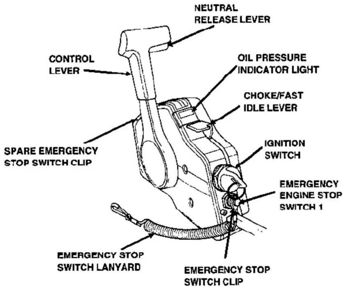
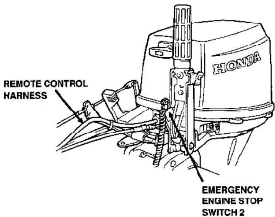
3. PRE-OPERATION CHECKS
Steering friction bolt
Operate the steering wheel right and left and check for the amount of drag felt.
Adjust the steering friction bolt so that a slight amount of drag is felt. The steering should move smoothly and freely.
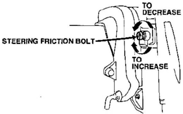
Remote control friction adjustment
Operate the remote control lever into forward and reverse gears and check for the amount of drag felt.
Adjust the remote control friction adjuster so that a slight amount of drag is felt. The remote control lever should move smoothly and freely.
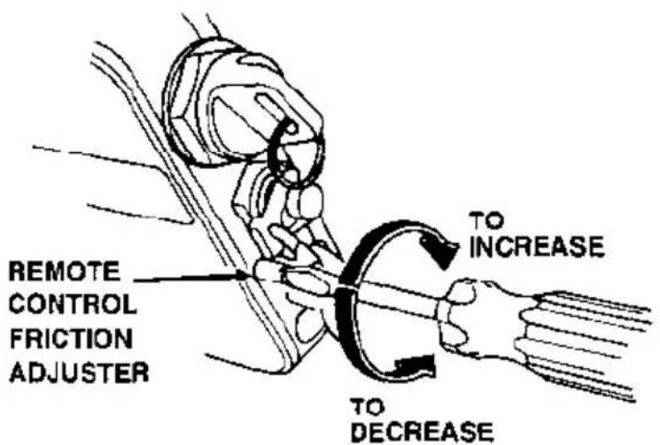
In addition to the above items review the pre-operation check list shown in the BF9.9A/15A owner's manual page 14.
Controls
Remote control lever
The remote control lever controls gear selection and throttle opening positions. It is necessary to pull up the neutral release lever to operate the remote control lever.
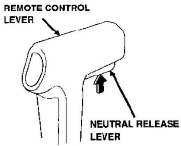
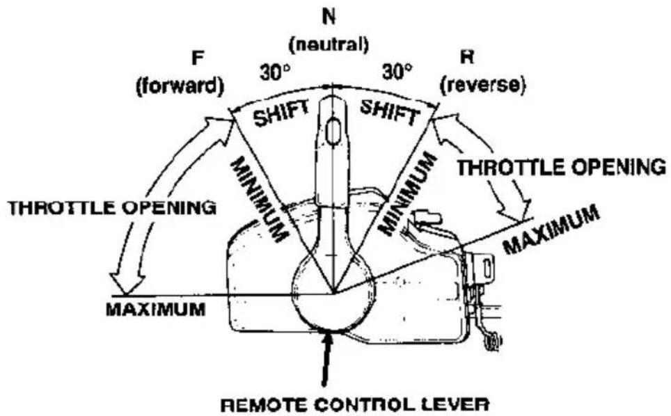
F (forward):
Moving the lever to the F position (approximately 30° from the N position) will engage the forward gear. Moving the lever farther from the F position will increase the throttle opening and the boat forward speed.
N (neutral):
The engine idles and the transmission gears are disengaged.
R (reverse):
Moving the lever to the R position (approximately 30° from the N position) will engage the reverse gear. Moving the lever farther from the R position will increase the throttle opening and the boat reverse speed.
5. STARTING THE ENGINE
Neutral release lever
The neutral release lever is on the remote control lever to prevent an accidental gear engagement.
The remote control lever will not engage forward or reverse gear unless the neutral release lever is pulled up.
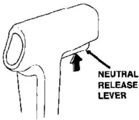
Ignition switch
The remote control box is equipped with a key type ignition switch.
Key positions:
START
To activate the starter motor and start the engine. The remote control lever must be in the neutral position.
ON
To run the engine after starting.
The battery will discharge if the key is left in this position with the engine not running.
OFF
To stop the engine (IGNITION OFF).
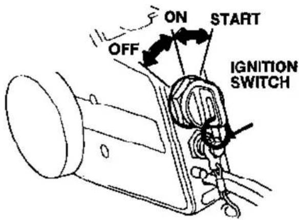
Emergency stop switch lanyard
The emergency stop switch lanyard is provided to stop the engine immediately in the event the operator should fall overboard or away from the controls.
The emergency stop switch clip must be engaged with the emergency engine stop switch or the engine will not start. When the emergency stop switch clip becomes disengaged from the emergency engine stop switch the engine will stop immediately.
The emergency engine stop switch should not be used to normally stop the engine. Use the ignition switch to normally stop the engine.
Attach the emergency stop switch lanyard securely to the operator when operating the outboard motor.
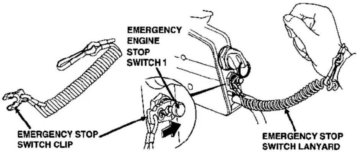
A spare emergency stop switch clip is provided on the remote control box.
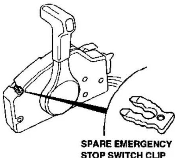
Choke/Fast idle lever
The choke/fast idle lever provides two functions:
- Electric choke solenoid activation for easy engine start up.
- Engine fast idle.
The choke/fast idle lever will not move unless the remote control lever is in the N (neutral) position. Conversely, the remote control lever will not move unless the choke/fast idle lever in the lowest position.
Lift and hold the choke/fast idle lever up fully, this will provide a rich fuel mixture and the correct fast idle. Do not run the engine while holding the lever in the choke position.
Gradually lower the choke/fast idle lever to the lowest position to decrease the choke and fast idle.
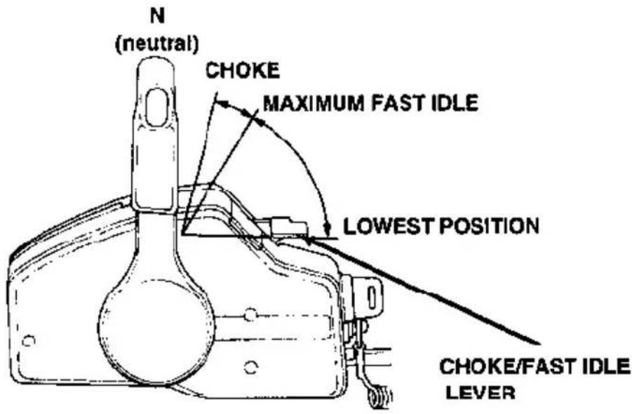
Manual choke knob
A manual choke knob is provided on the left side of the motor which can be used in the event the battery is discharged. When recoil starting, pull the choke knob and a rich fuel mixture will be provided to the engine. After the engine starts, be sure to push in the choke knob.
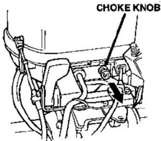
Oil pressure indicator light
The green oil pressure indicator light turns OFF when the oil level is low and/or the engine lubrication system is faulty.
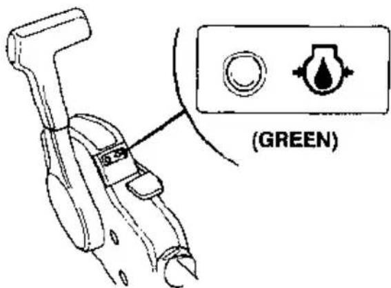
Fuel line connection
Refer to the BF9.9A/15A owner's manual page 15.
Electric starting (ignition key)
NOTICE
The anti-ventilation plate must be lowered into the water and be at least 2 inches below the surface. Running the outboard motor out of the water will damage the water pump and overheat the engine.
- Engage the emergency stop switch clip located at one end of the emergency stop switch lanyard with the emergency engine stop switch 1. Attach the other end of the emergency engine stop switch lanyard securely to the operator.
The engine will not start unless the emergency stop switch clip is engaged with the emergency engine stop switch.
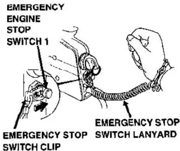
WARNING
If the operator does not attach the emergency stop switch lanyard, and is thrown from his seat or out of the boat, the out-of-control boat can seriously injure the operator, passengers, or bystanders. Always properly attach the lanyard before starting the motor.
A spare emergency stop switch clip is provided on the remote control box.
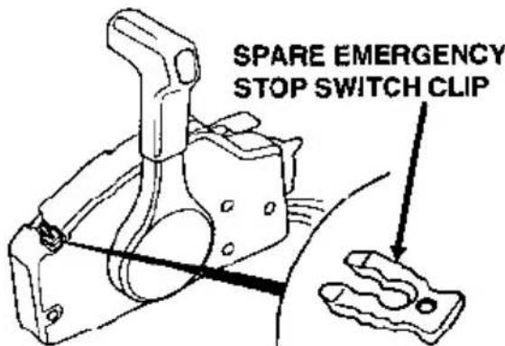
- Move the control lever to the N (neutral) position.
The engine will not start unless the control lever is in the N (neutral) position.
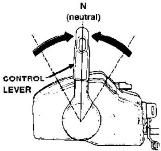
- When the engine is cold and/or the ambient temperature is low, lift and hold the choke/fast idle lever up fully. This will provide a rich fuel mixture and the correct fast idle.
When the engine is warm, it may be necessary to raise the choke/fast idle lever slightly. Hold it in this position.
The choke/fast idle lever will not move unless the control lever is in the N (neutral) position.
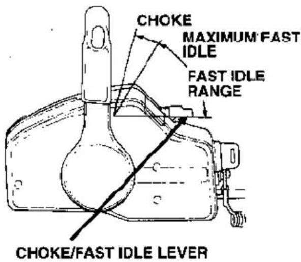
- While holding the choke/fast idle lever in the up position, turn the ignition key to the START position and release the key when the engine starts. The starter motor consumes a large amount of current. Do not run it continuously for more than 5 seconds at a time. If the engine does not start within 5 seconds wait at least 10 seconds before using the starter motor again.
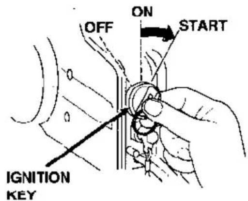
NOTICE
Do not turn the ignition key to the start position while the engine is running. This can damage the starter motor and flywheel.
5. STARTING THE ENGINE
- After starting the engine, return the lever slowly to the position where the engine does not stall. Hold the lever in position.
The control lever will not move unless the choke/fast idle lever is returned to the lowest position.
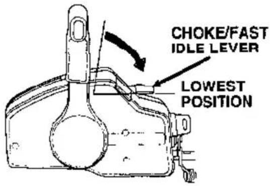
- After the engine starts, verify water is flowing through the water check hole. The amount of water coming out of the water check hole will vary due to thermostat operation. Stop the engine if water does not come out the water check hole or if you see steam. Check the water intake screens and the water check hole port and if necessary remove any obstructions. If the problem continues, contact your closest authorized Honda Marine or Honda Outboard Motor dealer.
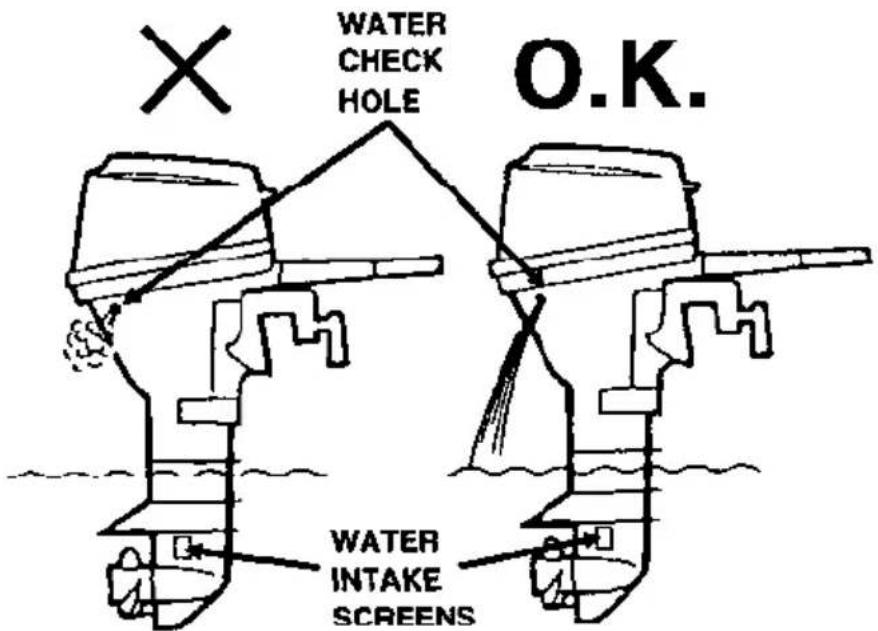
NOTICE
Running the outboard motor with an obstruction in the cooling system can damage the water pump and overheat the engine.
- With the engine running, check to see if the green engine oil pressure indicator light turns ON.
Stop the engine if the oil pressure indicator light does not turn ON. Check the engine oil level. If the oil level is normal and the oil pressure indicator light does not turn ON, contact your closest authorized Honda Marine or Honda Outboard Motor dealer.
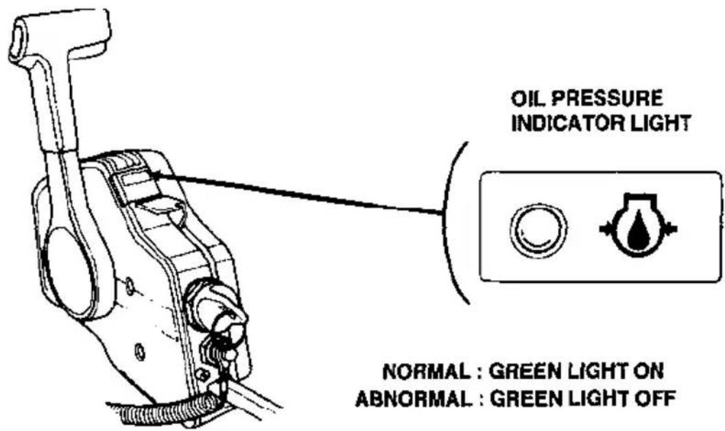
Recoil starting
If the electric starting system will not start the engine. The engine can be started using the recoil starter.
- Move the control lever to the N (neutral) position.
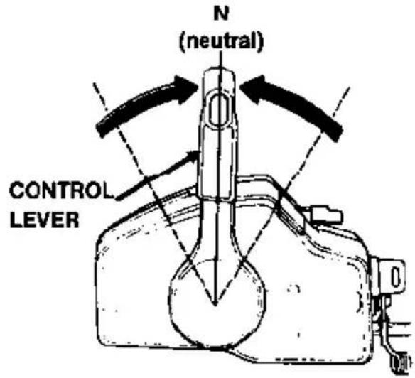
- Turn the ignition key to the ON position. Engage the emergency stop switch clip, located at one end of the emergency stop switch lanyard, with emergency engine stop switch 1.
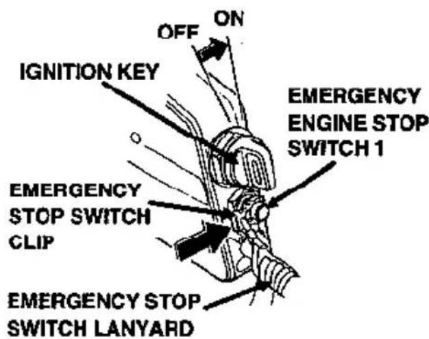
- Engage an emergency stop switch clip with emergency engine stop switch 2.
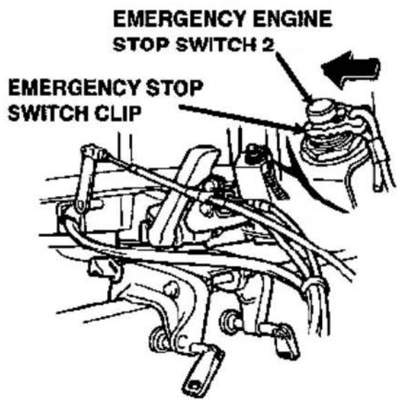
- If the engine is cold and/or the ambient temperature is low, pull and hold the manual choke knob out. The choke knob is located on the front of the outboard motor.
If the fuel system is working properly, it should only be necessary to pull the recoil starter 1 or 2 times with the choke knob out.
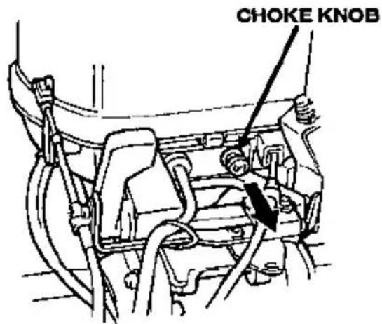
- Lift the choke/fast idle lever. The choke/fast idle lever will stay up in the fast idle position.
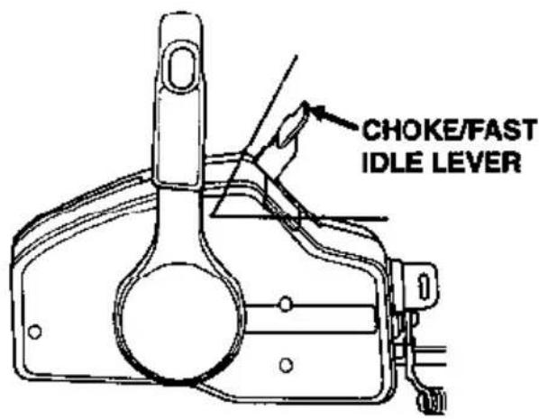
-
Pull the recoil starter rope slowly until resistance is felt, then pull briskly.
-
If it was necessary to use the manual choke knob to start the engine, slowly return it to its initial position.
-
Slowly return the choke/fast idle lever to the lowest position to where the engine does not stall.
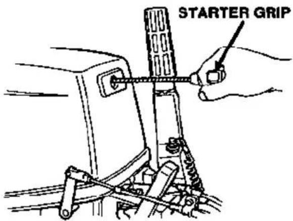
- After the engine starts, monitor the water discharge and the oil pressure indicator light.
5. STARTING THE ENGINE
Electric starting (starter button)
If the choke solenoid kit is not installed or not working, the engine can be started using the starter button on the side of the engine.
-
Perform steps 1 \~ 5 in this supplement (pages 14,15).
-
Press the electric starter button and start the engine.
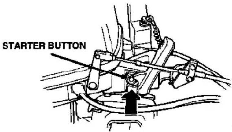
- Perform steps 7 \~ 9 in this supplement (page 15).
Emergency starting
If the electric starting system and/or the recoil starter will not start the engine. The engine can be started using the spare starter rope from the tool kit.
- Perform steps 1 \~ 5 in this supplement (pages 14,15)
- Perform steps 1 \~ 4 in the BF9.9A/15A owner's manual (page 20).
- Perform steps 7 \~ 9 in this supplement (page 15)
- Perform step 5 in the BF9.9A/15A owner's manual (page 20).
Gear shifting
While pulling up the neutral release lever, move the control lever 30° toward F (forward) or 30° toward R (reverse) to engage the desired gear.
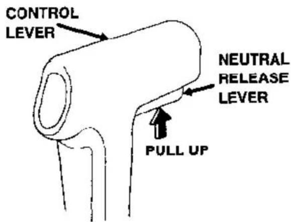
Moving the control lever farther from 30° will increase throttle opening and boat speed.
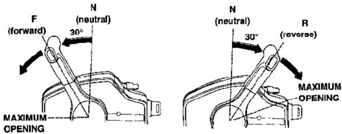
The control lever will not move unless the neutral release lever is pulled up and the choke/fast idle lever is in the lowest position.
For optimum fuel economy, limit throttle opening to 23 .
Emergency engine stop
Disengage the emergency stop switch clip from either emergency engine stop switch 1 or 2 by pulling the emergency stop switch lanyard.
It is a good idea to stop the engine with the emergency stop switch lanyard from time to time to be sure that the switch is operating properly.
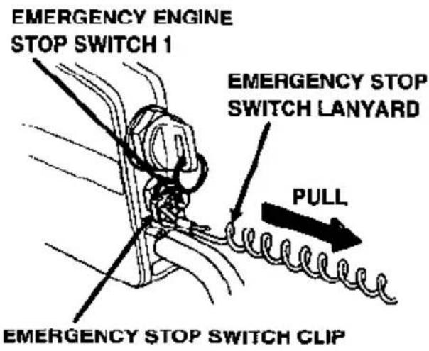
Normal engine stop
- Move the control lever to the N (neutral) position.
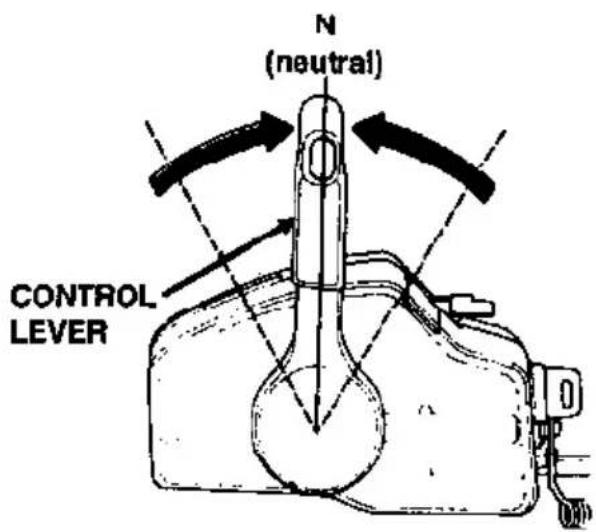
- Turn the ignition key to the OFF position.
When the boat is not in use, remove and store the ignition key.
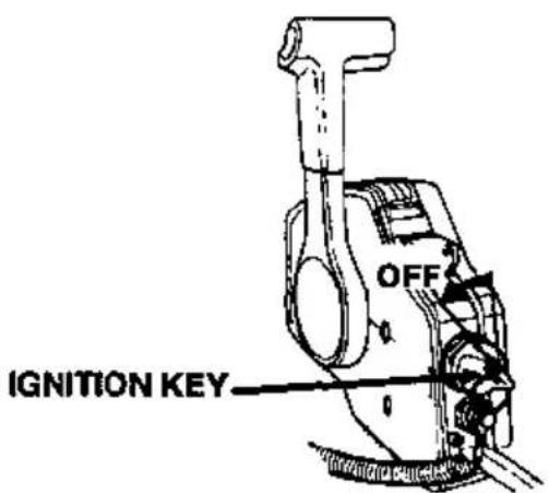
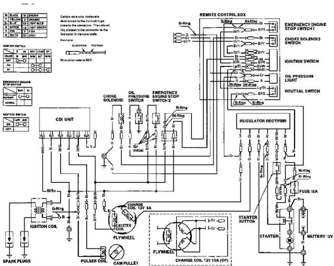
- WIRING DIAGRAM
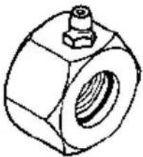
natural_image
Technical line drawing of a hexagonal nut with a central hole and a small protrusion (no text or symbols)Steering Tube Seal (Anodized Aluminum or Stainless Steel)
There are additional optional parts available. See your authorized Honda Marine or Honda Outboard Motor dealer for a complete list.
HONDA
31ZV460A
00X31-ZV4-600A
2509307
PRINTED IN U.S.A.
HONDA
31ZV4631
00X31-ZV4-6310

Printed on Recycled Paper
KINKOS
EM 50.2002.08
PRINTED IN U.S.A.
- INTRODUCTION
- A FEW WORDS ABOUT SAFETY
- CONTENTS
- OUTBOARD MOTOR SAFETY 7
- CONTROLS & FEATURES 10
- INSTALLATION 19
- BEFORE OPERATION 25
- OPERATION 27
- SERVICING YOUR HONDA OUTBOARD MOTOR 40
- HELPFUL TIPS & SUGGESTIONS 57
- TAKING CARE OF UNEXPECTED PROBLEMS 61
- TECHNICAL & CONSUMER INFORMATION 66
- INDEX 78
- QUICK REFERENCE INFORMATION......Inside back cover
- OUTBOARD MOTOR SAFETY
- IMPORTANT SAFETY INFORMATION
- Operator Responsibility
- Refuel With Care
- Carbon Monoxide Hazard
- SAFETY LABEL LOCATIONS
- CONTROLS & FEATURES
- COMPONENT & CONTROL LOCATIONS
- CONTROLS
- Engine Stop Switch
- Choke Knob
- Throttle Grip
- Throttle Friction Knob
- Gearshift Lever
- Recoil Starter Grip
- Electric Starter Button (models equipped with electric starter)
- Steering Friction Bolt
- Tilt Lever
- Transom Angle Adjusting Rod
- Engine Cover Lock Lever
- Fuel Priming Bulb
- Fuel Cap Vent Knob
- FEATURES
- Fuel Gauge
- Oil Prssure Indicator Light
- Water Check Hole
- Anode
- Overrev Limiter
- NOTICE
- INSTALLATION
- WARNING
- INSTALLATION POSITION
- INSTALLATION HEIGHT
- OUTBOARD MOTOR ATTACHMENT
- MOTOR ANGLE FOR CRUISING
- MOTOR ANGLE ADJUSTMENT
- BATTERY CONNECTIONS
- Models With Electric Starter
- Models Without Electric Starter
- Battery Installation
- EMERGENCY PROCEDURES
- Connections to the Battery
- BEFORE OPERATION
- ARE YOU READY TO GET UNDERWAY?
- Knowledge
- Safety Apparel
- Safety Inspection
- Maintenance Inspection
- OPERATION
- SAFE OPERATING PRECAUTIONS
- BREAK-IN PROCEDURE
- PORTABLE FUEL TANK PLACEMENT AND CONNECTIONS
- Fuel Tank Placement
- Fuel Hose Connections
- Fuel Priming
- STARTING THE ENGINE
- EMERGENCY STARTING
- STOPPING THE ENGINE
- Emergency Engine Stopping
- Normal Engine Stopping
- GEAR SHIFTING
- STEERING
- CRUISING
- TILTING THE OUTBOARD MOTOR
- SERVICING YOUR HONDA OUTBOARD MOTOR
- THE IMPORTANCE OF MAINTENANCE
- MAINTENANCE SAFETY
- Safety Precautions
- TOOL KIT AND SPARE PARTS
- Tool Kit
- REFUELING
- Fuel tank capacity
- US gal (12.0 ℓ, 2.6 Imp gal)
- ⚠ WARNING
- FUEL RECOMMENDATIONS
- Use unleaded gasoline with a pump octane rating of 86 or higher.
- COOLING SYSTEM CLEANING AND FLUSHING
- Cleaning and Flushing With the Flush Kit
- Cleaning and Flushing Without the Flush Kit
- ENGINE OIL LEVEL CHECK
- ENGINE OIL CHANGE
- ENGINE OIL RECOMMENDATIONS
- GEAR OIL LEVEL CHECK
- GEAR OIL CHANGE
- LUBRICATION
- SPARK PLUG SERVICE
- Recommended spark plugs:
- FUEL FILTER REPLACEMENT
- RECOIL STARTER ROPE INSPECTION
- ANODE REPLACEMENT
- PROPELLER REPLACEMENT
- HELPFUL TIPS & SUGGESTIONS
- STORING YOUR OUTBOARD MOTOR
- Storage Preparation
- Cleaning and Flushing
- Fuel
- Engine Oil
- Storage Precautions
- Removal From Storage
- TRANSPORTING
- TAKING CARE OF UNEXPECTED PROBLEMS
- ENGINE WILL NOT START
- ENGINE OVERHEATS
- BATTERY DOES NOT CHARGE AND ELECTRIC STARTER (applicable models) DOES NOT OPERATE
- Fuse Replacement
- SUBMERGED MOTOR
- TECHNICAL & CONSUMER INFORMATION
- TECHNICAL INFORMATION
- Serial Number Locations
- Carburetor Modification for High Altitude Operation
- Oxygenated Fuels
- ETHANOL
- MTBE
- METHANOL
- Emission Control System Information
- Source of Emissions
- The U.S. Clean Air Act
- Tampering and Altering
- Problems That May Affect Emissions
- Replacement Parts
- Maintenance
- CONSUMER INFORMATION
- Honda Publications
- Shop Manual
- Parts Catalog
- Warranty Service Information
- INDEX
- A
- B
- C
- E
- F
- G
- H
- 1
- L
- M
- N
- 0
- P
- Q
- R
- \$
- T
- W
- MEMO
- Owner's Manual
- Outboard Motor BF9.9A/15A
- SAFETY
- PRE-OPERATION CHECKS
- Remote control friction adjustment
- Remote control lever
- F (forward):
- N (neutral):
- R (reverse):
- STARTING THE ENGINE
- Neutral release lever
- Ignition switch
- START
- ON
- OFF
- Emergency stop switch lanyard
- Choke/Fast idle lever
- Manual choke knob
- Oil pressure indicator light
- Fuel line connection
- Electric starting (ignition key)
- Recoil starting
- Electric starting (starter button)
- Emergency engine stop
- Normal engine stop
- HONDA
Brand : Honda
Model : BF15A (2000)
Category : Outboard motor