BF40D (2014) - Outboard motor Honda - Free user manual and instructions
Find the device manual for free BF40D (2014) Honda in PDF.


| Product Type | Outboard Motor |
| Brand | Honda |
| Model | BF40D (2014) |
| Engine Type | 4-Stroke, OHV, 2-Cylinder |
| Displacement | 808 cm³ (49.3 cu in) |
| Maximum Power | 29.4 kW (40 HP) at 5000-6000 rpm |
| Fuel System | Programmed Fuel Injection (PGM-FI) |
| Fuel Type | Unleaded Gasoline (87 octane or higher) |
| Fuel Tank Capacity | 25 L (6.6 US gal) (external) |
| Starting System | Electric Start |
| Engine Weight | 95 kg (209 lb) |
| Transom Height | L (508 mm) or X (635 mm) shaft |
| Gear Ratio | 2.33:1 |
| Propeller | 3-blade, aluminum or stainless steel |
| Tilt & Trim | Power Trim & Tilt |
| Safety Features | Emergency stop switch, over-rev limiter, oil pressure warning |
| Maintenance | Oil change every 100 hrs, spark plugs every 200 hrs, gear oil annually |
| Spare Parts | Propeller, oil filter, fuel filter, anodes, spark plugs |
| Repairability | Modular design with accessible components; dealer service recommended |
Frequently Asked Questions - BF40D (2014) Honda
User questions about BF40D (2014) Honda
0 question about this device. Answer the ones you know or ask your own.
Ask a new question about this device
Download the instructions for your Outboard motor in PDF format for free! Find your manual BF40D (2014) - Honda and take your electronic device back in hand. On this page are published all the documents necessary for the use of your device. BF40D (2014) by Honda.
USER MANUAL BF40D (2014) Honda
BF40D·BF50D Owner's Manual
Click to \$ave As
natural_image
Silhouette of a person wearing a helmet and holding a device, against a blue grid background (no text or symbols)Includes US and Canadian Models
WARNING:
The engine exhaust from this product contains chemicals known to the State of California to cause cancer, birth defects, or other reproductive harm.
Keep this Owner's Manual handy, so you can refer to it at any time. This Owner's Manual is considered a permanent part of the outboard motor and should remain with the outboard motor if resold.
© 2013 Honda Motor Co., Ltd. – All Rights Reserved
The information and specifications included in this publication were in effect at the time of approval for printing. Honda Motor Co., Ltd. reserves the right, however, to discontinue or change specifications or design at any time without notice and without incurring any obligation whatever. No part of this publication may be reproduced without written permission.
INTRODUCTION
Congratulations on your selection of a Honda outboard motor. We are certain you will be pleased with your purchase of one of the finest outboard motors on the market.
We want to help you get the best results from your new outboard motor and to operate it safely. This manual contains information on how to do that; please read it carefully.
As you read this manual you will find information preceded by a
NOTICE symbol. That information is intended to help you avoid damage to your outboard motor, other property, or the environment.
We suggest you read the warranty policy to fully understand its coverage and your responsibilities of ownership.
When your outboard motor needs scheduled maintenance, keep in mind that your Honda Marine dealer is specially trained in servicing Honda outboard motors. Your Honda Marine dealer is dedicated to your satisfaction and will be pleased to answer your questions and concerns.
Best Wishes, Honda Motor Co., Ltd.
INTRODUCTION
A FEW WORDS ABOUT SAFETY
Your safety and the safety of others are very important. And using this outboard motor safely is an important responsibility.
To help you make informed decisions about safety, we have provided operating procedures and other information on labels and in this manual. This information alerts you to potential hazards that could hurt you or others.
Of course, it is not practical or possible to warn you about all the hazards associated with operating or maintaining an outboard motor. You must use your own good judgment.
You will find important safety information in a variety of forms, including:
- Safety Labels – on the outboard motor.
- Safety Messages – preceded by a safety alert symbol ⚠️ and one of three signal words, DANGER, WARNING, or CAUTION.
These signal words mean:
You WILL be KILLED or SERIOUSLY HURT if you don't follow instructions.

You CAN be KILLED or SERIOUSLY HURT if you don't follow instructions.

You CAN be HURT if you don't follow instructions.
- Safety Headings – such as IMPORTANT SAFETY INFORMATION.
- Safety Section – such as OUTBOARD MOTOR SAFETY.
- Instructions – how to use this outboard motor correctly and safely.
This entire book is filled with important safety information – please read it carefully.
CONTENTS
OUTBOARD MOTOR SAFETY 7
IMPORTANT SAFETY INFORMATION ...... 7
SAFETY LABEL LOCATIONS 9
CONTROLS AND FEATURES 13
CONTROL AND FEATURE IDENTIFICATION CODES 13
COMPONENT AND CONTROL LOCATIONS ... 14
CONTROLS 20
LH and LHT Types (tiller handle) 20 Ignition Switch 20
Emergency Stop Switch Clip and Emergency Stop Switch 20
Throttle Grip 21
Throttle Friction Adjuster 22
Gearshift Lever 22
Steering Friction Adjuster 22
Transom Angle Adjusting Rod 23
Tilt Lever 23
LRT and XRT Types (remote control/ side-mount control type) [standard equipment (LRTC type)], [optional equipment (LRTA and XRTA types)] 24
Ignition Switch 24
Emergency Stop Switch Clip and Emergency Stop Switch 25
Gearshift/Throttle Control Lever 26
Fast Idle Lever 27
LHT, LRT and XRT Types (power trim/tilt)
Power Trim/Tilt Switch 28
Power Tilt Switch (engine pan) 28
Manual Relief Valve 29
Except LHA and LHTC types TRL (Trolling) Control Switch [optional equipment]....29
Common Controls ....30
Tilt Lock Lever 30
Engine Cover Latches ....30
Trim Tab 30
INSTRUMENTS 31
Trim Meter [standard equipment (Canadian types)], [optional equipment (LRTA and XRTA types)] ....31
Tachometer [standard equipment (Canadian types)], [optional equipment (LRTA and XRTA types)] ....31
Fuel Gauge [standard equipment (Canadian types)], [optional equipment (American types)] ....31
CONTENTS
INDICATORS 32
Alternator (ACG) Indicator 32
Malfunction Indicator 32
Oil Pressure Indicator 33
Overheat Indicator 34
Cooling System Indicator 34
OTHER FEATURES 35
Overrev Limiter 35
Portable Fuel Tank [standard equipment (Canadian types)], [optional equipment (American types)] ..... 35
Fuel Filler Cap Vent Knob 36
Fuel Priming Bulb 36
NMEA Interface Coupler 36
Anodes 37
BEFORE OPERATION 38
ARE YOU READY TO GET UNDERWAY? ..... 38
IS YOUR OUTBOARD MOTOR READY TO GO? 38
Tiller Handle Height/Angle Adjustment (LH and LHT types) 40
OPERATION 41
SAFE OPERATING PRECAUTIONS ....41
BREAK-IN PROCEDURE 41
TRANSOM ANGLE ADJUSTMENT (LH Type) ..42
PORTABLE FUEL TANK [standard equipment (Canadian types)] [optional equipment (American types)] .....43
FUEL HOSE CONNECTIONS ....43
FUEL PRIMING 44
INFREQUENT OR OCCASIONAL USE .....45
STARTING THE ENGINE ....45 LH and LHT Types (tiller handle) ....45
LRT and XRT Types (remote control) Side-Mount Control Type ....48
EMERGENCY STARTING ....51
STOPPING THE ENGINE ....54 Emergency Engine Stopping ....54 Normal Engine Stopping ....55
GEARSHIFT AND THROTTLE OPERATION ....57 LH and LHT Types (tiller handle) ....57 LRT and XRT Types (remote control) ....58
STEERING ....59 LH and LHT Types (tiller handle) ....59
Steering Friction Adjuster 59
LRT and XRT Types (remote control) .....59
CONTENTS
CRUISING 60
TRIM TAB 63
TOOL KIT and OWNER'S MANUAL 69
MAINTENANCE SCHEDULE 70
TRIM TAB ADJUSTMENT 72
MANUAL RELIEF VALVE 73
ENGINE COVER REMOVAL AND INSTALLATION 73
Engine Oil Level Check 74
Engine Oil Change 76
Engine Oil Recommendations 78
Spark Plug Service 78
Lubrication Points 80
REFUELING 81
FUEL RECOMMENDATIONS 83
Fuel Filter/Water Separator Inspection and Service ....84
Portable Fuel Tank and Tank Filter Cleaning [standard equipment (Canadian types)], [optional equipment (American types)] .....87
Anode Replacement 88
Propeller Replacement ....89
CLEANING AND FLUSHING 91
Cleaning and Flushing 91
STORAGE 94
Fuel 94
Engine Oil 97
HOISTING THE OUTBOARD MOTOR .....97
STORAGE PRECAUTIONS 97
REMOVAL FROM STORAGE 98
TRANSPORTING 99
WITH OUTBOARD MOTOR INSTALLED ON BOAT 99
WITH OUTBOARD MOTOR REMOVED FROM BOAT 99
CONTENTS
TAKING CARE OF UNEXPECTED PROBLEMS ... 100
ENGINE WILL NOT START 100
HARD STARTING OR STALLS AFTER STARTING 103
ENGINE OVERHEATS 104
FUSES 105
Electric Starter Will Not Operate 105
Battery Will Not Charge 105
Fuse Replacement 106
OIL PRESSURE INDICATOR GOES OFF AND ENGINE SPEED IS LIMITED 107
OVERHEAT INDICATOR COMES ON AND ENGINE SPEED IS LIMITED 108
SUBMERGED OUTBOARD MOTOR 110
TECHNICAL INFORMATION ....112
Serial Number Locations 112
Battery 113
Emission Control System Information .....113
Star Label 116
Specifications 118
CONSUMER INFORMATION 121
Honda Publications ......121
Customer Service Information ....121
Warranty Statements 124
Distributor's Limited Warranty 124
Emission Control System Warranty 129
Distributor's Warranty ....133
INDEX 136
OUTBOARD MOTOR SAFETY
IMPORTANT SAFETY INFORMATION
The Honda BF40D/BF50D outboard motors are designed for use with boats that have a suitable manufacturer's power recommendation. Other uses can result in injury to the operator or damage to the outboard motor and other property.
Most injuries or property damage can be prevented if you follow all instructions in this manual and on the outboard motor. The most common hazards are discussed in this chapter, along with the best way to protect yourself and others.
Operator Responsibility
- It is the operator's responsibility to provide the necessary safeguards to protect people and property. Know how to stop the engine quickly in case of emergency. Understand the use of all controls.
-
Stop the engine immediately if anyone falls overboard, and do not run the engine while the boat is near anyone in the water.
• Always stop the engine if you must leave the controls for any reason. -
Attach the emergency stop switch lanyard securely to the operator.
• Always wear a PFD (Personal Flotation Device) while on the boat. - Familiarize yourself with all laws and regulations relating to boating and the use of outboard motors.
- Be sure that anyone who operates the outboard motor receives proper instruction.
- Be sure the outboard motor is properly mounted on the boat.
- Do not remove the engine cover while the engine is running.
OUTBOARD MOTOR SAFETY
Refuel With Care
- Gasoline is extremely flammable, and gasoline vapor can explode. Refuel outdoors, in a well-ventilated area, with the engine stopped. Never smoke near gasoline, and keep other flames and sparks away.
- Refuel carefully to avoid spilling fuel. Avoid overfilling the fuel tank.
• After refueling, tighten the filler cap securely. If any fuel is spilled, make sure the area is dry before starting the engine.
Carbon Monoxide Hazard
Exhaust contains poisonous carbon monoxide, a colorless, odorless gas. Breathing carbon monoxide can cause loss of consciousness and may lead to death.
If you run the engine in an area that is confined, or even partly enclosed, the air you breathe could contain a dangerous amount of exhaust gas.
Never run your outboard inside a garage or other enclosure.
SAFETY LABEL LOCATIONS
US, Puerto Rico, and US Virgin Islands Types
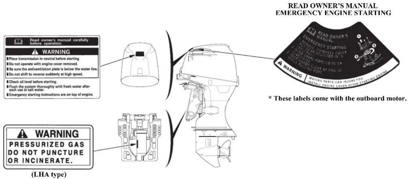
The label shown here contains important safety information. Please read it carefully. This label is considered a permanent part of your outboard motor. If the label comes off or becomes hard to read, contact an authorized Honda Marine dealer for a replacement.
OUTBOARD MOTOR SAFETY
SAFETY LABEL LOCATIONS
Canadian Types
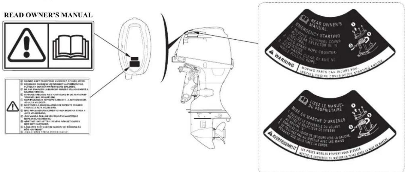
* These labels come with the outboard motor.
The label shown here contains important safety information. Please read it carefully. This label is considered a permanent part of your outboard motor. If the label comes off or becomes hard to read, contact an authorized Honda Marine dealer for a replacement.
OUTBOARD MOTOR SAFETY
![PORTABLE FUEL TANK [standard equipment (Canadian types)] [optional equipment (American types)] FUEL CAUTION FLAMMABLE DANGEROUS GASOLINE REMOVE FROM BOAT FOR FILLING 4T 1 2 3 4 INFLAMMABLE DANGEREUX GAZOLINE SOBTIR DU BATEAU POUR REFAIRE LE PLEIND ESSENCE GASOLINE EXTREMELY FLAMMABLE FOR USE AS A MOTOR FUEL ONLY - MAY CONTAIN LEAD ANTI-KNOCK COMPOUNDS DANGER HARMFUL OR FATAL: IF SWALLOWED. KIEP OUT OF REACH OF CHILDREN. IF SWALLOWED. DO NOT INDUCE VOMITING. CALL A PHYSICIAN IMMEDIATELY. CAUTION KEEP TOTALLY CLOSED WHEN NOT IN USE. KEEP AWAY FROM HEAT SPARKS AND OPEN FLAME SECURE ABOVE DECK IN WELL VENTILATED AREA. DO NOT USE FOR LONG TERM FUEL STORAGE. DO NOT USE FULL/OL MIXTURE/COLLOW MOTOR MANUFACTURERS RECOMMENDATIONS.](/content/2026/06/1277068/images/2c95eb06453e4259deabca77c20808e9c7c02277ad01aad8645ad57e0049a9df.jpg)
OUTBOARD MOTOR SAFETY
Canadian Types
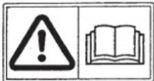
- Honda outboard motor is designed to give safe and dependable service if operated according to instructions. Read and understand the Owner's Manual before operating the outboard motor. Failure to do so could result in personal injury or equipment damage.
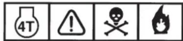
- Gasoline is harmful or fatal if swallowed. Keep the fuel tank out of reach of children.
- Gasoline is extremely flammable and is explosive under certain conditions. Refuel in a well-ventilated area with the engine stopped.
- Do not smoke or allow flames or sparks where the engine is refueled or where gasoline is stored.
- Do not overfill the fuel tank. After refueling make sure that the fuel tank cap is closed properly and securely.
- Be careful not to spill any fuel while refueling. Spilled fuel or fuel vapor may ignite. If any fuel is spilled, make sure that the area is dry before starting the engine.
CONTROLS AND FEATURES
CONTROL AND FEATURE IDENTIFICATION CODES
| Model BF40D BF50D | ||||||||
| Type LHA LRTA LRTC LHTC LRTA LRTC XRTA | ||||||||
| Shaft Length | L ● | ● ● ● | ● ● | |||||
| X ● | ||||||||
| Tiller Handle ● ● | ||||||||
| Remote Control | ● ● | ● | ● ● | |||||
| Gas Assist Tilt | ● | |||||||
| Power Trim/Tilt | ● ● | ● ● ● | ● | |||||
| Tachometer | * | ● | ● | * | ● | * | ||
| Trim Meter | * | ● | ● | * | ● | * | ||
| TRL (Trolling) Control Switch | * | * | * | * | * | |||
*: Optional equipment
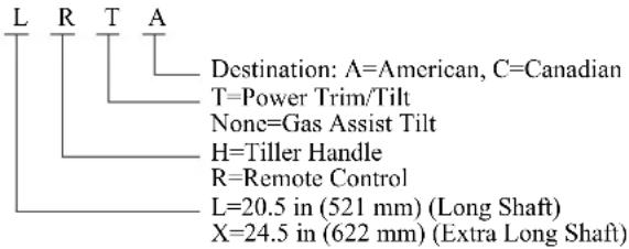
Refer to this chart for an explanation of the Type Codes used in this manual to identify control and feature applications.
TYPE CODE (Example)
COMPONENT AND CONTROL LOCATIONS
LH and LHT Types
![(tiller handle) SPARK PLUG (inside the cover) ENGINE COVER ENGINE OIL FILLER CAP POWER TRIM/ TILT SWITCH (LHT type only) ENGINE COVER LATCH (front) ENGINE COVER LATCH (rear) TILLER HANDLE FUEL LINE CONNECTOR STERN BRACKET POWER TILT SWITCH (LHT type only) OIL LEVEL DIPSTICK COOLING SYSTEM INDICATOR IDLE PORT TILT LOCK LEVER TILT LEVER (LH type only) TRANSOM ANGLE ADJUSTING ROD ANODE METAL TRIM TAB ANODE METAL (each side) ENGINE OIL DRAIN BOLT COVER MANUAL RELIEF VALVE (LHT type only) EXHAUST PORT/ WATER OUTLET PORT ANTIVENTILATION PLATE COOLING WATER INTAKE PORT WASH SCREW GEAR OIL CHECK SCREW GEAR OIL DRAIN/FILL SCREW PROPELLER [standard equipment (Canadian types)] [optional equipment (American types)]](/content/2026/06/1277068/images/a0c30b4c564ce999280f30c7c973deae50d3db0fd1c0dc650adbf9df4492fee9.jpg)
LRT and XRT Types (remote control)
![SPARK PLUG (inside the cover) ENGINE COVER LATCH (front) ENGINE OIL FILLER CAP ENGINE COVER LATCH (rear) FUEL LINE CONNECTOR STERN BRACKET POWER TILT SWITCH IDLE PORT ANODE METAL (each side) TRIM TAB EXHAUST PORT/ WATER OUTLET PORT PROPELLER [standard equipment (Canadian types)] [optional equipment (American types)] WEAR OIL DRAIN/FILL SCREW WASH SCREW TILT LOCK LEVER COOLING SYSTEM INDICATOR ENGINE OIL DRAIN BOLT COVER ANTIVENTILATION PLATE COOLING WATER INTAKE PORT MANUAL RELIEF VALVE](/content/2026/06/1277068/images/2960a3980788d6bbd8701b94bd9d0ba84cd42ae2342ba04c24e27515d1197c46.jpg)
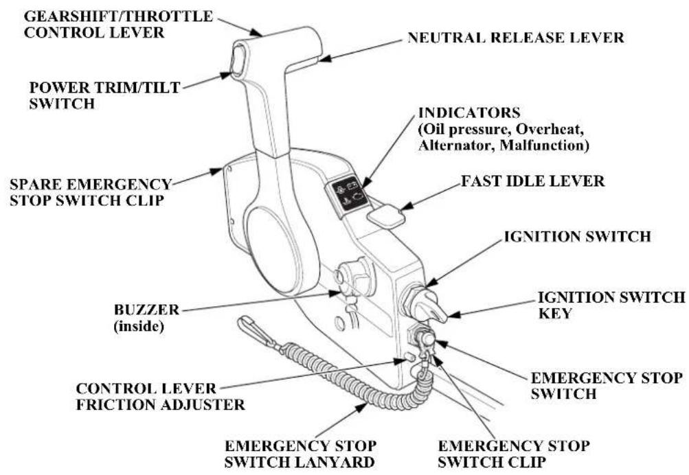
Remote Control Box
Side-Mount Control Type
[standard equipment (LRTC type)], [optional equipment (LRTA and XRTA types)]
CONTROLS AND FEATURES
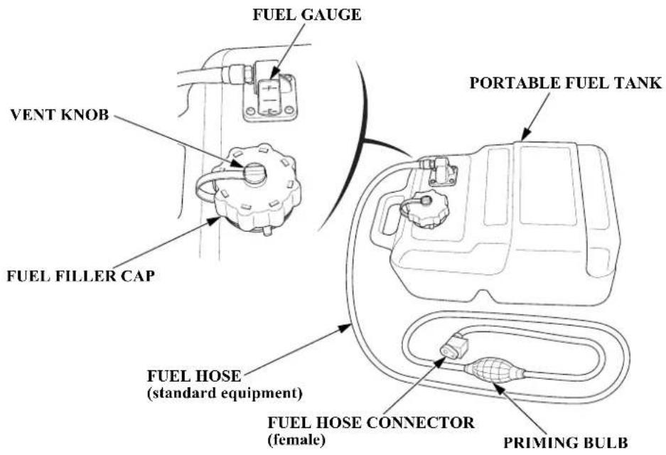
Portable Fuel Tank
[standard equipment (Canadian types)]
[optional equipment (American types)]
CONTROLS AND FEATURES
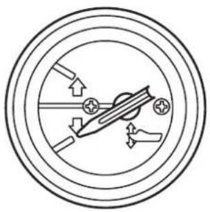
Trim Meter
[standard equipment (Canadian types)]
[optional equipment (LRTA and XRTA types)]
natural_image
Pure diagram of a mechanical or electrical component inside concentric circles, without any text, numbers, or symbols.Tachometer
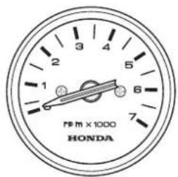
[standard equipment (Canadian types)]
[optional equipment (LRTA and XRTA types)]
Trolling Control Switch Panel [optional equipment (other LHA and LHTC types)]
flowchart
graph TD
    A["UP"] --> B["TRU"]
    B --> C["DN"]
    C --> D["Directional Arrow"]
    D --> E["Up/Down"]
TRL (Trolling) CONTROL SWITCH
CONTROLS AND FEATURES
CONTROLS
LH and LHT Types (tiller handle)
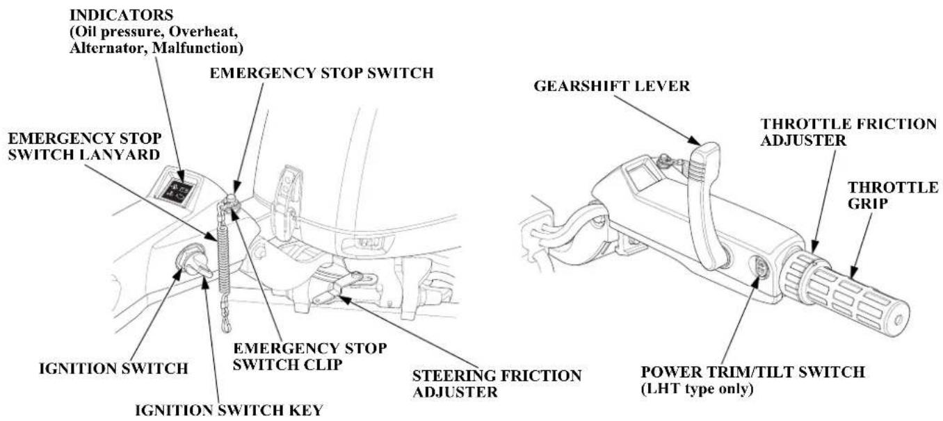
Ignition Switch
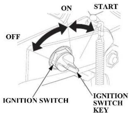
The ignition switch controls the ignition system and the starter motor.
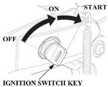
Turning the ignition switch key to the START position operates the starter motor. The key automatically returns to the ON position when released from the START position.
The engine will not start unless the gearshift lever is in the N (neutral) position (p. 45) and the emergency stop switch clip is in the emergency stop switch.
Turning the ignition switch to the OFF position stops the engine.
Emergency Stop Switch Clip and Emergency Stop Switch
CONTROLS AND FEATURES
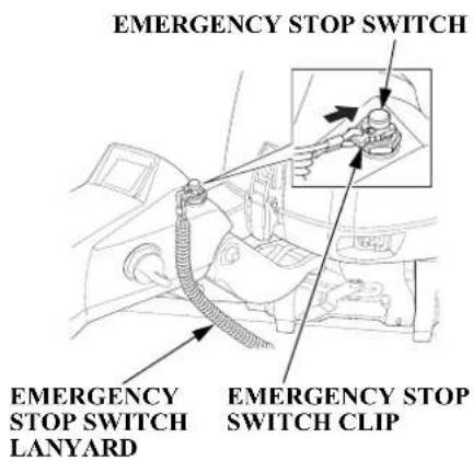
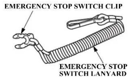
The emergency stop switch clip must be inserted in the emergency stop switch in order for the engine to start and run. The emergency stop switch lanyard must be attached securely to the operator or to the operator's PFD (Personal Flotation Device).
When used as described, the emergency stop switch and emergency stop switch lanyard system stops the engine if the operator falls away from the controls.
A spare switch clip is provided in the tool bag (p. 69).
Throttle Grip
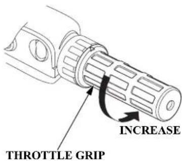
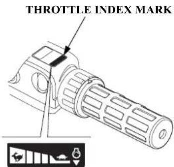
The throttle grip controls engine speed.
The throttle index mark shows throttle position and is helpful for setting the throttle correctly when starting (p. 46).
CONTROLS AND FEATURES
Throttle Friction Adjuster
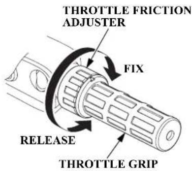
The throttle friction adjuster adjusts resistance to throttle grip rotation.
Turn the adjuster clockwise to increase friction for holding a throttle setting while cruising.
Turn the adjuster counterclockwise to decrease friction for easy throttle grip rotation.
Gearshift Lever
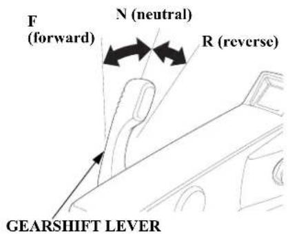
The gearshift lever is used to select F (forward), N (neutral), or R (reverse) gears.
The engine can be started with the gearshift lever in the N (neutral) position only.
Steering Friction Adjuster
STEERING FRICTION ADJUSTER
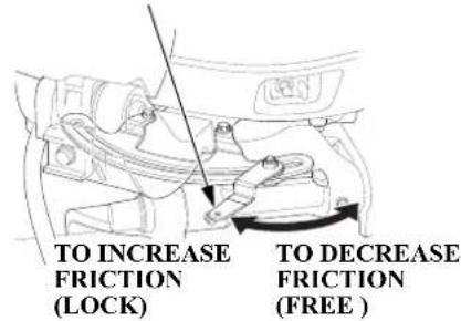
The steering friction adjuster adjusts steering resistance.
Less friction allows the outboard motor to turn more easily. More friction helps to hold a steady course while cruising or to prevent the outboard motor from swinging while trailering the boat.
Transom Angle Adjusting Rod (LH type)
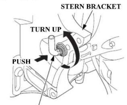
TRANSOM ANGLE ADJUSTING ROD (storage position)
TO CHANGE UNLOCKED POSITION
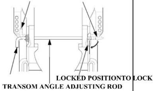
The transom angle adjusting rod limits the tilt angle of the outboard motor when fully lowered.
Proper adjustment prevents the outboard motor from being trimmed too low (p. 60).
There are five transom angle adjustment positions. Four are controlled by the adjusting rod and the fifth is controlled by the stern bracket. In order to use the fifth position, remove the adjusting rod and store it in the storage location, then lower the outboard motor down to the stern bracket stop position.
Tilt Lever (LH type)
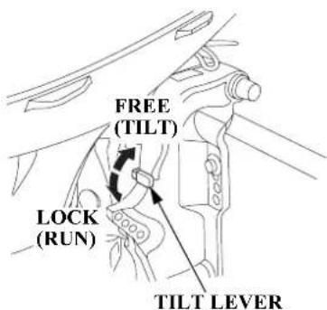
Moving the tilt lever to the FREE (TILT) position allows the outboard motor to be tilted and moving the tilt lever to the LOCK (RUN) position locks the outboard motor in the desired position. Use the tilt lever to temporarily tilt the outboard motor when the boat is operating in shallow water, or mooring in shallow water. The tilt lever must be in the LOCK (RUN) position before operating the outboard motor or the outboard motor could tilt up when operating in reverse.
CONTROLS AND FEATURES
LRT and XRT Types (remote control/side-mount control type) [standard equipment (LRTC type)] [optional equipment (LRTA and XRTA types)]
For panel-mount or top-mount remote control information, refer to the instructions provided with the remote control equipment.
Ignition Switch
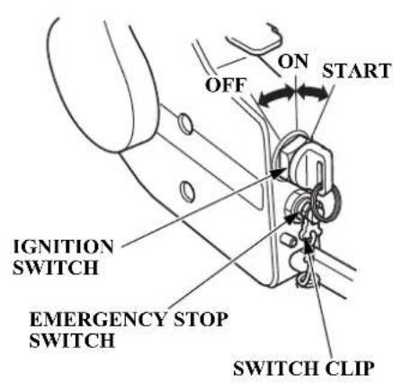
The ignition switch controls the ignition system and the starter motor.
Turning the ignition switch key to the START position operates the starter motor. The key automatically returns to the ON position when released from the START position.
The ignition switch can be used to start the engine only when the control lever is in the N (neutral) position (p. 48) and the emergency stop switch clip is in the emergency stop switch.
Turning the ignition switch to the OFF position stops the engine.
Emergency Stop Switch Clip and Emergency Stop Switch
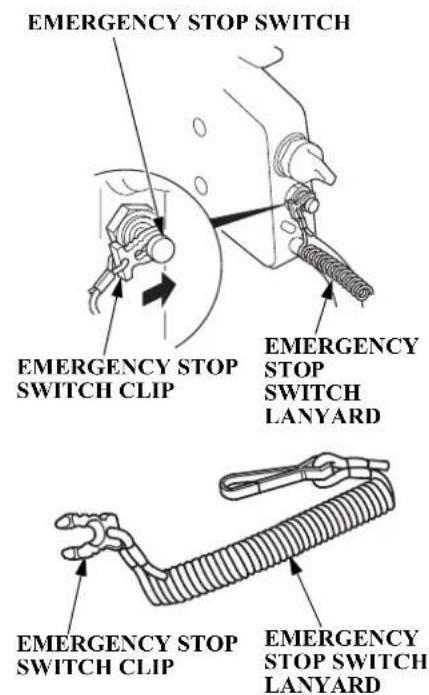
The emergency stop switch clip must be inserted in the emergency stop switch in order for the engine to start and run. The emergency stop switch lanyard must be attached to the operator's PFD (Personal Flotation Device) or to the operator securely.
When used as described, the emergency stop switch clip and emergency stop switch lanyard system stops the engine if the operator falls away from the controls.
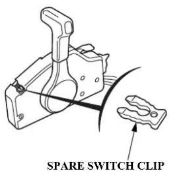
A spare switch clip is stored in a slot in the control housing.
CONTROLS AND FEATURES
Gearshift/Throttle Control Lever
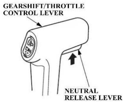
The gearshift/throttle control lever controls engine speed and selects F (forward), N (neutral), or R (reverse) gears.
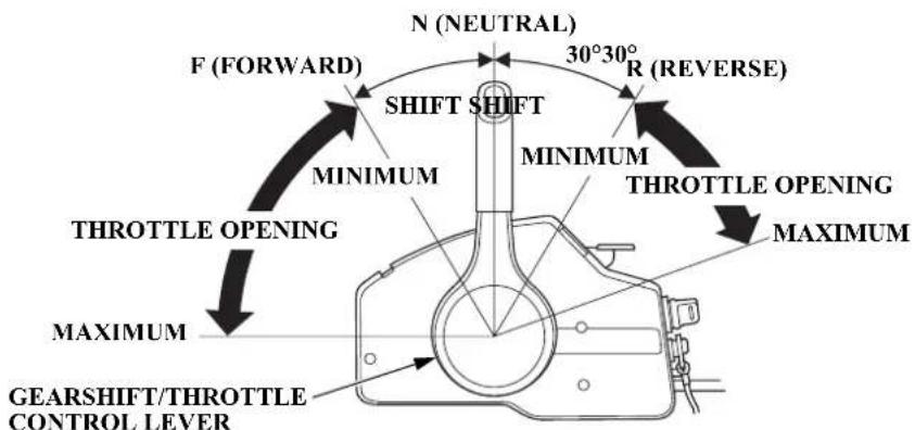
Moving the control lever 30^ from N (neutral) selects the gear, and further movement increases engine speed.
The control lever automatically locks itself in the N (neutral) position. To move the lever out of the N (neutral) position, you must squeeze the neutral release lever on the underside of the lever handle.
A friction adjuster near the base of the control lever adjusts the operating resistance of the control lever. Refer to p. 58.
Less friction allows easier control lever movement. More friction helps to hold a steady throttle setting while cruising.
Fast Idle Lever
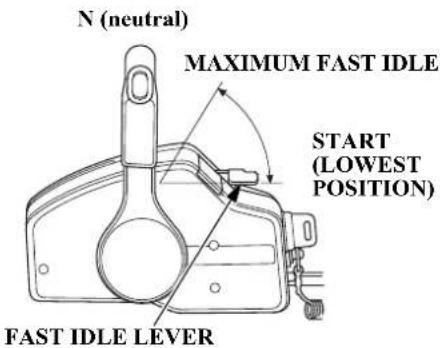
Use the fast idle lever to accelerate engine warm-up after starting the engine. Do not use the fast idle lever when starting the engine.
See page 50 for engine warm-up instructions.
The fast idle lever allows you to increase the idle speed only when the control lever is in the N (neutral) position. Place the fast idle lever in its START (fully lowered) position to cancel the fast idle and return the control lever to normal operation.
CONTROLS AND FEATURES
LHT, LRT and XRT Types (power trim/tilt)
Power Trim/Tilt Switch
LHT Type
TILLER HANDLE
LRT and XRT Types
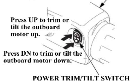
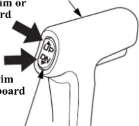
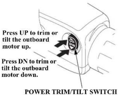
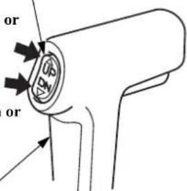
Press UP to trim or tilt the outboard motor up.
CONTROL LEVER
Press DN to trim or tilt the outboard motor down.
POWER TRIM/TILT SWITCH
The power trim/tilt switch is located on the control lever. It is a rocker switch with UP and DN (down) positions for changing the angle of the outboard motor.
You can use the power trim/tilt switch anytime whether the boat is underway, stopped, or the ignition switch is in the OFF position. It is necessary for the ignition switch to be in the ON position for the trim meter to indicate the outboard motor angle. Trim the outboard motor to obtain the best performance and stability (p. 60).
Tilt the outboard motor for shallow water operation, beaching, launching, or mooring.
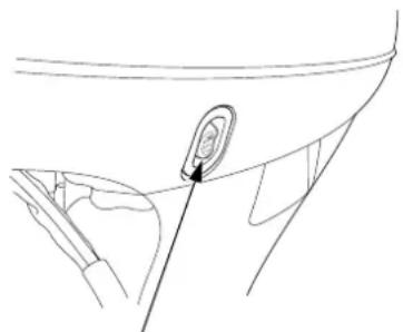
Power Tilt Switch (engine pan)
natural_image
Line drawing of a car interior showing a circular component inserted into the seat area (no text or symbols)POWER TILT SWITCH
The power tilt switch is located on the engine pan. It is a rocker switch with UP and DN (down) positions for changing the angle of the outboard motor.
The power tilt switch will operate without turning the ignition switch ON.
This switch is used with the engine stopped to raise the outboard motor for mooring, trailering, or maintenance.
CONTROLS AND FEATURES
Manual Relief Valve
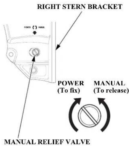
The outboard motor can be tilted manually after opening the manual relief valve. This allows the outboard motor to be tilted up or down when no battery is connected.
Check that nobody is under the outboard motor before opening the manual relief valve. If the manual relief valve is loosened (turned counterclockwise) when the outboard motor is tilted up, the outboard motor will suddenly tilt down.
Except LHA and LHTC types TRL (Trolling) Control Switch [optional equipment]
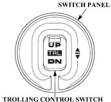
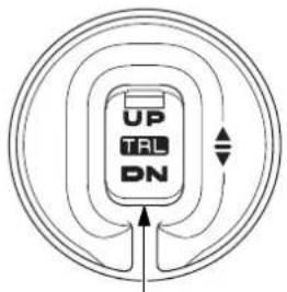
The Trolling Control Switch is a rocker switch with UP and DN (down) positions to adjust the trolling speed up or down in 50 RPM increments within the range of 800 to 1,100 RPM.
If you press and hold the TRL control switch while cruising with the throttle closed, the mode changes to trolling mode (p. 62)
CONTROLS AND FEATURES
Common Controls
Tilt Lock Lever
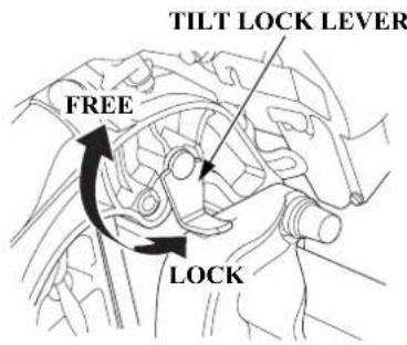
The tilt lock lever is used to support the outboard motor in the fully-raised position.
When the boat is to be moored for a long time, tilt the outboard motor up as far as it will go. Then move the tilt lock lever to the LOCK position, and gently lower the outboard motor until the lever contacts the stern bracket.
Engine Cover Latches
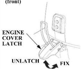
(front)
(rear)
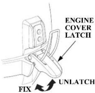
The engine cover latches fasten the engine cover to the outboard motor.
Trim Tab
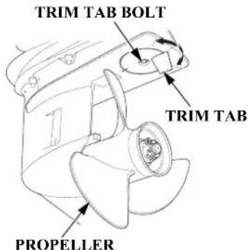
The trim tab compensates for “torque steer,” which is a reaction of the outboard motor to propeller rotation.
If uncompensated, torque steer would make the outboard motor tend to turn to one side.
When the trim tab is correctly adjusted (p. 72), steering effort is equal in either direction.
INSTRUMENTS
Trim Meter
[standard equipment (Canadian types)]
[optional equipment (LRTA and XRTA types)]
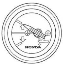
The trim meter indicates the relative trim angle of the outboard motor.
Refer to the trim meter when using the power trim/tilt switch to achieve the best performance from the boat.
Tachometer
[standard equipment (Canadian types)]
[optional equipment (LRTA and XRTA types)]
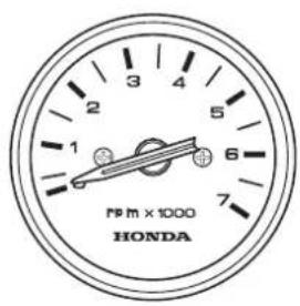
The tachometer shows engine speed in revolutions per minute.
Refer to the tachometer when using the throttle and power trim/tilt controls to achieve the best performance from the boat.
Fuel Gauge
[standard equipment (Canadian types)]
[optional equipment (American types)]
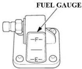
A fuel gauge is built into the fuel tank connector of the portable fuel tank.
INDICATORS
The indicator lights come on and the buzzer sounds when you turn the ignition switch ON, allowing you to see that they are working. If an indicator does not light during this test, it cannot alert you if that system develops a problem. Have your Honda Marine dealer check for burned-out bulbs or other problems. Under normal conditions, the following occur when the ignition switch is turned ON:
- The ACG, Malfunction, Oil Pressure, and Overheat indicators light.
- The buzzer will beep twice.
- The Malfunction, Oil Pressure, and Overheat indicators will go out after the second beep.
- The ACG indicator will go out after the engine starts.
- The Oil Pressure indicator will light again after the engine starts and will stay lit to indicate the oil pressure is normal.
Alternator (ACG) Indicator
LH and LHT Types
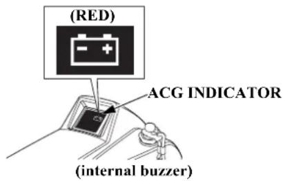
LRT and XRT Types
(side-mount control)
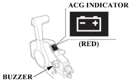
The ACG indicator turns on and the buzzer sounds in one-second intervals when the charging system is faulty.
Malfunction Indicator
LH and LHT Types
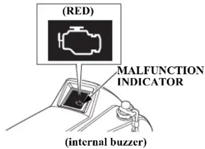
LRT and XRT Types
(side-mount control)
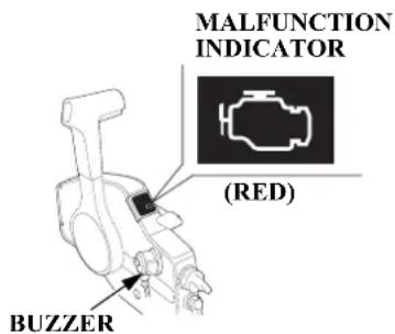
CONTROLS AND FEATURES
When the engine control system detects an engine control system malfunction, the malfunction indicator turns on and the buzzer sounds at one-second intervals.
Oil Pressure Indicator
LH and LHT Types
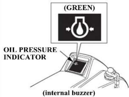
LRT and XRT Types (side-mount control)
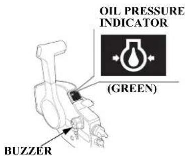
When the oil pressure indicator is lit, oil pressure is OK.
If oil pressure becomes low, the indicator will go off, and the engine protection system will limit engine speed. Refer to TAKING CARE OF UNEXPECTED PROBLEMS, on p. 107.
All models are equipped with a buzzer that sounds continuously when the oil pressure indicator goes off.
Low oil pressure indicates that the engine oil level is low or that there is a problem with the engine lubrication system.
CONTROLS AND FEATURES
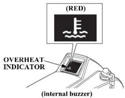
Overheat Indicator
LH and LHT Types
LRT and XRT Types (side-mount control)
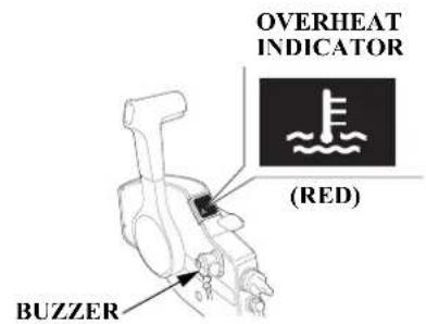
When the alert triggers, the overheat indicator comes on and the buzzer sounds a steady tone as the engine speed is reduced to 1,800 rpm. If the condition persists for another 20 seconds, the engine shuts off. Refer to TAKING CARE OF UNEXPECTED PROBLEMS, on p. 108.
All models are equipped with a buzzer that sounds continuously when the red light comes on.
Engine overheating may be the result of clogged water intakes.
Cooling System Indicator
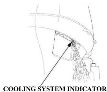
Water should flow from the cooling system indicator while the engine is running. This shows that water is circulating through the cooling system.
If water stops flowing while the engine is running, it indicates a cooling system problem, such as clogged water intakes, which will cause engine overheating. Refer to TAKING CARE OF UNEXPECTED PROBLEMS, on p. 108.
CONTROLS AND FEATURES
The cooling system indicator discharge port can also become plugged.
OTHER FEATURES
Overrev Limiter
The engine is equipped with an overrev limiter to prevent the possibility of mechanical damage from excessive engine speed.
The overrev limiter may be activated during operation, limiting engine speed, if the outboard motor is trimmed or tilted up excessively, or when propeller ventilation occurs during a sharp turn.
If the overrev limiter is activated, check the trim angle of the outboard motor.
Check to see if the correct propeller is installed.
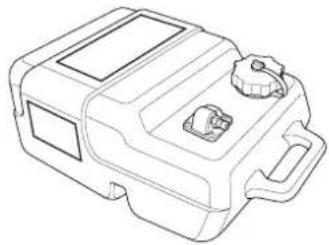
Portable Fuel Tank [standard equipment (Canadian types)] [optional equipment (American types)]
natural_image
Line drawing of a mechanical device with handle and internal components (no text or symbols)The portable fuel tank has a capacity of 6.6 US gal (25 L) and has a fuel gauge built into the fuel tank connector.
CONTROLS AND FEATURES
Fuel Filler Cap Vent Knob
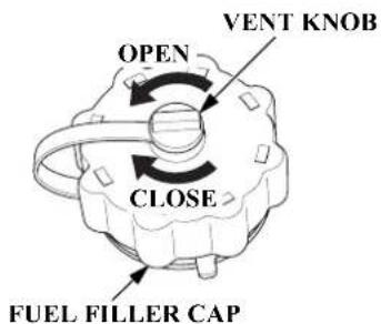
The fuel filler cap is provided with a vent knob to seal the portable fuel tank for carrying it to and from the boat. Open the vent by turning the vent knob counterclockwise all the way before starting the engine.
Fuel Priming Bulb
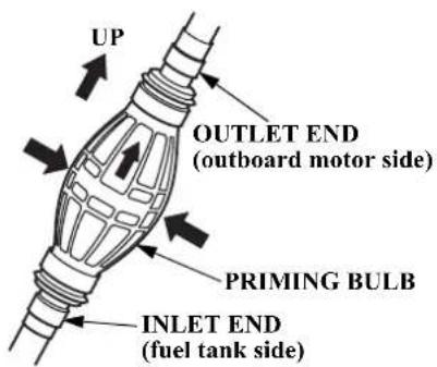
A priming bulb is built into the fuel hose that connects the fuel tank to the outboard motor.
Before starting the engine, hold the priming bulb up in the direction of the arrow; then squeeze the priming bulb until it feels firm. This will ensure that fuel is supplied to the engine (p. 44).
NMEA Interface Coupler
The NMEA2000 ^® interface coupler can provide information regarding engine speed, fuel consumption, and various warnings to an existing NMEA2000 network via an optional interface cable. Contact your dealer for more information.
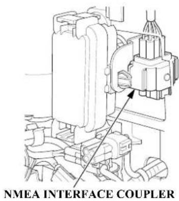
CONTROLS AND FEATURES
Anodes
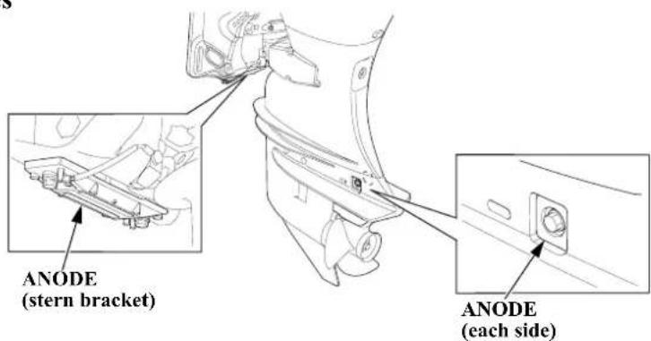
The anodes are made of a sacrificial material that helps to protect the outboard motor from corrosion.
There are two anodes on the gear case, one on the stern bracket and two small anodes in the water passages of the engine block.
BEFORE OPERATION
ARE YOU READY TO GET UNDERWAY?
Your safety is your responsibility. A little time spent in preparation will significantly reduce your risk of injury.
Knowledge
Read and understand this manual. Know what the controls do and how to operate them.
Familiarize yourself with the outboard motor and its operation before you get underway. Know what to do in case of an emergency.
Familiarize yourself with all laws and regulations relating to boating and the use of outboard motors.
Safety
Always wear a PFD (Personal Flotation Device) while on the boat.
Attach the emergency stop switch clip securely to the operator or to the operator's PFD (Personal Flotation Device).
For your safety, and to maximize the service life of your equipment, it is very important to take a few moments before you operate the outboard motor to check its condition. Be sure to take care of any problem you find, or have your authorized Honda Marine dealer correct it, before you operate the outboard motor.
WARNING
Improperly maintaining this outboard motor or failing to correct a problem before operation can cause a malfunction in which you could be seriously hurt or killed.
Always perform a pre-operation inspection before each operation, and correct any problem.
Before beginning your pre-operation checks, be sure the ignition switch is in the OFF position.
BEFORE OPERATION
Safety Inspection
- Before each use, look around underneath the engine for signs of oil or gasoline leaks.
- If you are using the portable fuel tank (standard or optional equipment), make sure it is in good condition and properly secured in the boat (p. 43).
- Check that the fuel hose is undamaged and properly connected.
- Wipe up any spills before starting the engine.
- Check the stern bracket to be sure the outboard motor is securely installed.
- Check that all controls are operating properly.
-
Replace any damaged parts.
-
Check that all fasteners are in place and securely tightened.
- Check the emergency stop switch for proper operation (p. 20, 25). Start the engine. Make sure the engine stops by pulling the emergency stop switch clip from the emergency stop switch (p. 54).
Maintenance Inspection
- Check the engine oil level (p. 74). Running the engine with a low oil level can cause engine damage.
- Check to be sure the propeller is undamaged and the castle nut is secured with the cotter pin (p. 89).
-
Check that the anodes are securely attached to the stern bracket and the gear case (p. 88) and are not excessively worn. The anodes help protect the outboard motor from corrosion.
-
Make sure a tool kit and the emergency starter rope are onboard (p. 69). Replace any missing items.
- Check the fuel level in the fuel tank (p. 81).
- Check that the battery fluid is between the upper and lower levels, and the battery leads are connected securely.
- Check the fuel filter for water contamination (p. 84).
BEFORE OPERATION
Tiller Handle Height/Angle Adjustment (LH and LHT types)
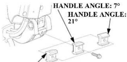
HANDLE ANGLE: 13°
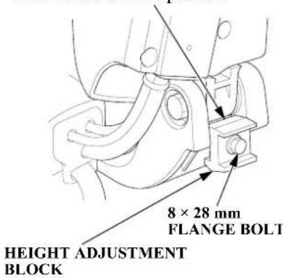
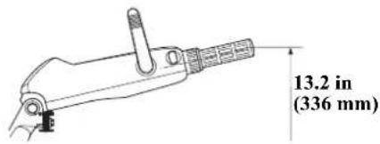
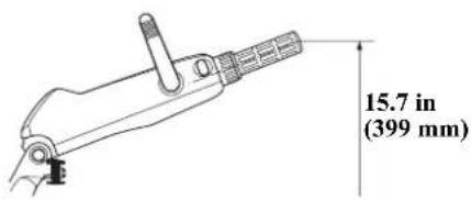
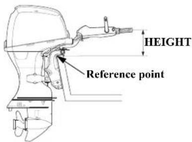
The tiller handle height and angle can be adjusted to three positions by changing the installation direction of the height adjustment block. Select a suitable height and angle for the operator and secure the block.
- Raise the tiller handle and remove the 8 × 28 mm flange bolt and the height adjustment block.
- Pull down the tiller handle. Determine the height adjustment block installation direction and secure the block with the 8 × 28 mm flange bolt.
Install the height adjustment block so that the selected angle of the tiller handle is in this position.
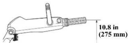
HANDLE ANGLE: 7°
HANDLE ANGLE: 13°
HANDLE ANGLE: 21°
OPERATION
SAFE OPERATING PRECAUTIONS
To safely realize the full potential of this outboard motor, you need a complete understanding of its operation and a certain amount of practice with its controls.
Before operating the outboard motor for the first time, please review the IMPORTANT SAFETY INFORMATION on page 7 and the chapter titled BEFORE OPERATION.
For your safety, do not start or run the engine in a confined or partly enclosed area. Your engine's exhaust contains poisonous carbon monoxide, a colorless, odorless gas that can collect rapidly. Breathing carbon monoxide can cause loss of consciousness and may lead to death.
BREAK-IN PROCEDURE
Break-in period: 10 hours
Proper break-in operation allows the moving parts to wear in smoothly for best performance and long service life. Avoid continuous operation at a steady speed.
First 15 minutes:
Run the engine at trolling speed. Use the minimum throttle opening necessary to operate the boat at a safe trolling speed.
Next 45 minutes:
Run the engine up to a maximum of 2,000 to 3,000 rpm, which is about 10% to 30% of maximum throttle opening. Operating at maximum 2,000 \~ 3,000 rpm should be limited to 50% of the 45 minutes.
Next 60 minutes:
Run the engine up to a maximum of 4,000 to 5,000 rpm, which is about 50% to 80% of maximum throttle opening. Operating at maximum 4,000 \~ 5,000 rpm should be limited to 50% of the 60 minutes. 30-second full-throttle bursts are OK, but do not operate the engine continuously at full throttle.
For boats that plane easily, bring the boat up on plane, and then reduce the throttle opening to the recommended rpm range.
Next 8 hours:
Do not run the engine at full throttle for more than 5 minutes at a time.
OPERATION
TRANSOM ANGLE
ADJUSTMENT (LH Type)
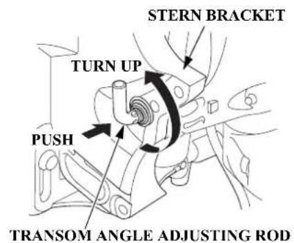
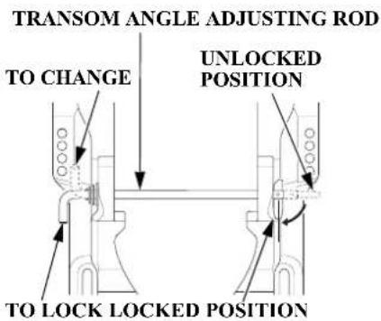
The transom angle adjusting rod limits the tilt angle of the outboard motor when fully lowered.
Proper adjustment prevents the outboard motor from being trimmed too low (p. 60).
To adjust, first tilt the outboard motor so it is not resting on the rod.
Push the rod in and turn the end of the rod up, so the latch will fall into line with the rod.
Remove the rod and reinsert it in the desired position.
Push the rod in and turn the end of the rod down, so the latch will fall to the locked position. Then release the rod.
NOTICE
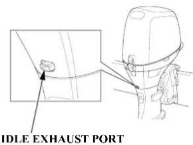
Do not allow water to enter the idle exhaust port or the engine can be damaged.
PORTABLE FUEL TANK [standard equipment (Canadian types)] [optional equipment (American types)]
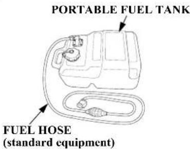
Place the portable fuel tank in a well-ventilated location, away from direct sunlight, to reduce the possibility of a gasoline vapor explosion.
To ensure that the outboard motor will be able to draw fuel from the tank, place the tank within 6 feet (2 m) of the outboard motor and not more than 3 feet (1 m) below the fuel connector on the outboard motor.
Secure the portable fuel tank in the boat so that it won't move around and become damaged.
WARNING
Gasoline is highly flammable and explosive.
You can be burned or seriously injured when handling fuel.
- Stop the engine and keep heat, sparks, and flame away.
- Handle fuel only outdoors.
- Wipe up spills immediately.
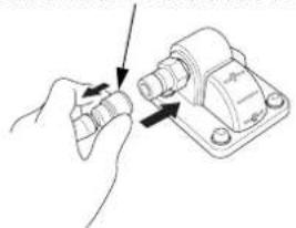
FUEL HOSE CONNECTIONS
Turn the portable fuel tank vent knob counterclockwise to the open position.
FUEL HOSE CONNECTOR
natural_image
Hand holding a mechanical component with arrows indicating assembly or adjustment (no text or symbols)(fuel tank side)
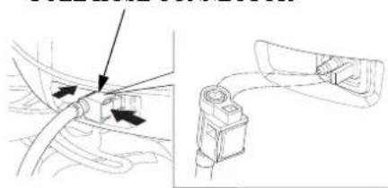
FUEL HOSE CONNECTOR
natural_image
Technical diagram showing a car's cable and connector assembly (no text or labels)(outboard motor side)
OPERATION
Connect the fuel hose to the tank and the outboard motor, as shown. Be sure both connectors snap securely into place. Always disconnect the fuel hose when storing or transporting the outboard motor.
FUEL PRIMING
If you are using a portable fuel tank, turn the portable fuel tank vent knob counterclockwise to the open position.
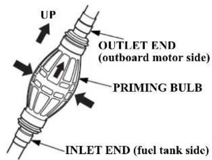
Hold the priming bulb up in the direction of the arrow; then squeeze the priming bulb several times until it feels firm, indicating that fuel has reached the engine.
Check to be sure there are no fuel leaks before starting the engine.
Do not touch the priming bulb with the engine running or when tilting up the outboard motor. The vapor separator could overflow.
WARNING
Gasoline is highly flammable and explosive.
You can be burned or seriously injured when handling fuel.
- Stop the engine and keep heat, sparks, and flame away.
- Handle fuel only outdoors.
- Wipe up spills immediately.
OPERATION
INFREQUENT OR OCCASIONAL USE
If your outboard motor will be used on an infrequent or intermittent basis, please refer to the fuel section of the STORAGE chapter (p. 94) for additional information regarding fuel deterioration.
STARTING THE ENGINE
Control Page
Side-Mount Control Type ..... 48
LH and LHT Types (tiller handle)
EMERGENCY STOP SWITCH
EMERGENCY STOP SWITCH LANYARD
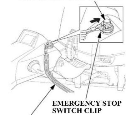
- Put the emergency stop switch clip in the emergency stop switch, and attach the emergency stop switch lanyard securely to the operator or to the operator's PFD (Personal Flotation Device).
The engine will not start or run unless the emergency stop switch clip is in the emergency stop switch.
The emergency stop switch clip and emergency stop switch lanyard system is a safety device that will stop the engine if you fall away from the controls while operating the boat.
Always attach the emergency stop switch lanyard securely to the operator or to the operator's PFD before starting the engine.
OPERATION
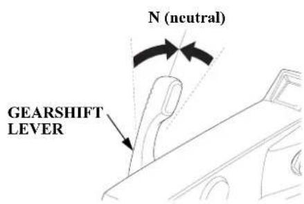
- Check the position of the gearshift lever. It must be in the N (neutral) position for starting.
The engine will not start if the gearshift lever is in the F (forward) or R (reverse) position.
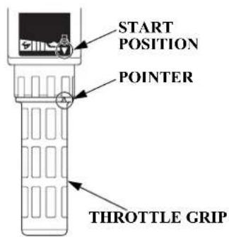
- Align the engine start symbol “” on the tiller handle with the pointer “▶” on the throttle grip.
-
Turn the ignition switch key to the ON position; the buzzer will sound twice.
-
Turn the ignition switch key to the START position and hold it there until the engine starts. When the engine starts, release the key, allowing it to return to the ON position.
If the engine fails to start within 5 seconds, release the key and wait at least 10 seconds before operating the starter again.
NOTICE
- Using the electric starter for more than 5 seconds at a time will overheat the starter motor and can damage it.
- Turning the ignition switch key to the START position while the engine is running can damage the starter motor and flywheel.
Also, as the engine warms up, the throttle grip can be turned to the SLOW position without stalling.
- Before getting underway, allow the engine to warm-up sufficiently to ensure good performance.
Above 41^ F ( 5^ C), warm-up the engine for at least 3 minutes.
Below 41^ F ( 5^ C), warm-up the engine for at least 5 minutes at 2,000 rpm.
NOTICE
- If the engine is not properly warmed up before raising the engine speed, the buzzer and overheat indicator may activate and the engine speed will be automatically reduced.
- The cooling system may freeze in areas where the temperature reaches 32^ ( 0^ ) or below. Cruising at high speed without warming the engine up may cause engine damage.
During the warm-up period, check the oil pressure indicator (p. 33), overheat indicator (p. 34), and cooling system indicator (p. 34).
If the indicators show any abnormal condition, immediately stop the engine and determine the cause of the problem. Refer to TAKING CARE OF UNEXPECTED PROBLEMS on p. 107 - 108.
OPERATION
LRT and XRT Types (remote control)
Side-Mount Control Type [standard equipment (LRTC type)] [optional equipment (LRTA and XRTA types)]
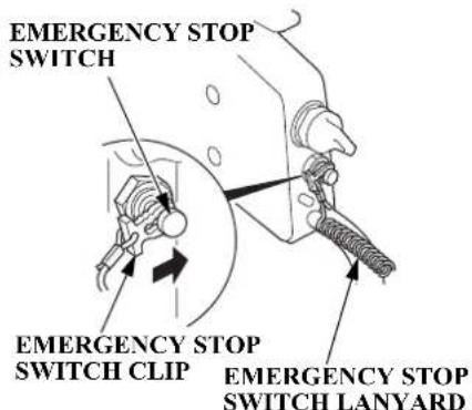
- Put the emergency stop switch clip in the emergency stop switch, and securely to the operator or to the operator's PFD (Personal Flotation Device).
The engine will not start or run unless the emergency stop switch clip is in the emergency stop switch.
The emergency stop switch clip and emergency stop switch lanyard system is a safety device that will stop the engine if you fall away from the controls while operating the boat.
Always attach the emergency stop switch lanyard securely to the operator or to the operator's PFD before starting the engine.
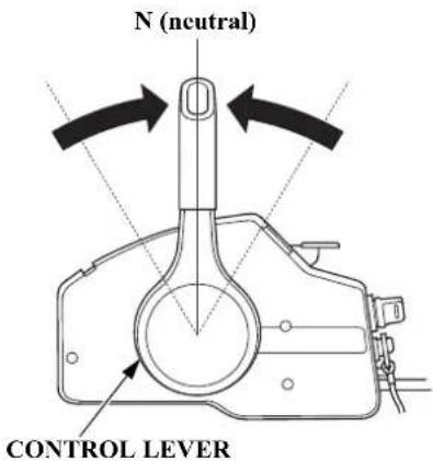
- Set the control lever in the N (neutral) position.
The engine will not start if the F (forward) or R (reverse) gears are engaged.
OPERATION
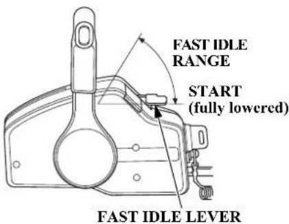
- Leave the fast idle lever in the START (fully lowered) position.
The fast idle lever cannot be raised unless the control lever is in the N (neutral) position.
The control lever cannot be moved away from the N (neutral) position unless the fast idle lever is lowered.
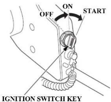
-
Turn the ignition switch key to the ON position; the buzzer will sound twice.
-
Turn the ignition switch key to the START position and hold it there until the engine starts.
When the engine starts, release the key, allowing it to return to the ON position.
If the engine fails to start within 5 seconds, release the key and wait at least 10 seconds before operating the starter again.
NOTICE
• Using the electric starter for more than 5 seconds at a time will overheat the starter motor and can damage it.
- Turning the ignition switch key to the START position while the engine is running can damage the starter motor and flywheel.
OPERATION
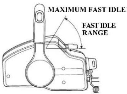
- Before getting underway, allow the engine to warm-up sufficiently to ensure good performance.
Above 41^ F ( 5^ C), warm-up the engine for at least 3 minutes.
Below 41^ F ( 5^ C), warm-up the engine for at least 5 minutes at 2,000 rpm. Raise the fast idle lever to achieve approximately 2,000 rpm.
NOTICE
- If the engine is not properly warmed up before raising the engine speed, the buzzer and overheat indicator may activate and the engine speed will be automatically reduced.
- The cooling system may freeze in areas where the temperature reaches 32^ (0^) or below. Cruising at high speed without warming the engine up may cause engine damage.
During the warm-up period, check the oil pressure indicator (p. 33), overheat indicator (p. 34), and cooling system indicator (p. 34).
If the indicators show any abnormal condition, immediately stop the engine and determine the cause of the problem. Refer to TAKING CARE OF UNEXPECTED PROBLEMS on p. 107 - 108.
- If the fast idle lever was used to warm-up the engine, gradually lower the lever as the engine warms up.
When the fast idle lever is fully lowered, the control lever can be moved away from the N (neutral) position.
EMERGENCY STARTING
If the battery is discharged or the starter motor is inoperative, you can start the engine manually using the emergency starter rope supplied with the outboard motor.
(front)
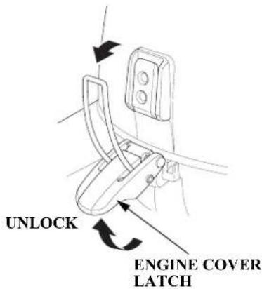
(rear)

- Turn the ignition switch key to the OFF position (p. 56).
- Unlatch the engine cover latches and remove the engine cover.
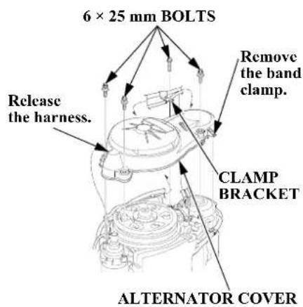
- Remove the four 6 × 25 mm bolts and clamp bracket, release the harness from the clamper, then remove the alternator cover.
- Install the clamp bracket with the 6 × 25 mm bolt.
NOTE:
Take care not to lose the bolts.
OPERATION
- Set the controls the same as for normal starting (p. 45 - 46, 48 - 49).
Turn the ignition switch key to the ON position.
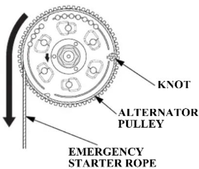
- Set the alternator pulley so the cutouts are on the right and left sides of the alternator pulley as shown. Hook the knot at the end of the starter rope (accessory) against a cutout in the alternator pulley, and wind the starter rope one and half turns counterclockwise along the groove in the alternator pulley.
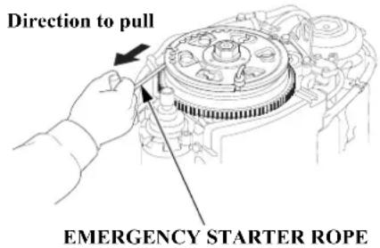
- Pull the emergency starter rope slowly until resistance is felt, then pull briskly.
Keep away from moving parts while pulling the rope.
If necessary, rewind the rope and pull again. If the engine does not start after several attempts, refer to TAKING CARE OF UNEXPECTED PROBLEMS on p. 100 - 102.
WARNING
Exposed moving parts can cause injury.
- Do not operate the outboard motor without the engine cover.
- Use extreme care when installing the engine cover.
OPERATION
- If the fast idle control(s) was used to start the engine, return the control(s) to the normal operating position as the engine warms up.
During the warm-up period, check the oil pressure indicator (p. 33), overheat indicator (p. 34), and cooling system indicator (p. 34).
-
Leave the alternator cover off, but install the engine cover (p. 73) and lock it in place by latching the engine cover latches.
-
If it was necessary to remove the emergency stop switch lanyard from you to perform the emergency starting procedure, be sure the lanyard is attached securely to operator before operating the outboard motor.
-
Have your closest authorized Honda Marine dealer check your electrical system and correct the problem so that you can use the electric starter.
OPERATION
STOPPING THE ENGINE
Emergency Engine Stopping
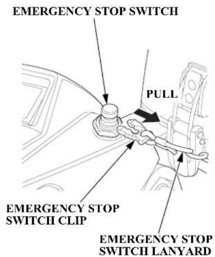
LH and LHT Types (tiller handle)
LRT and XRT Types (remote control)
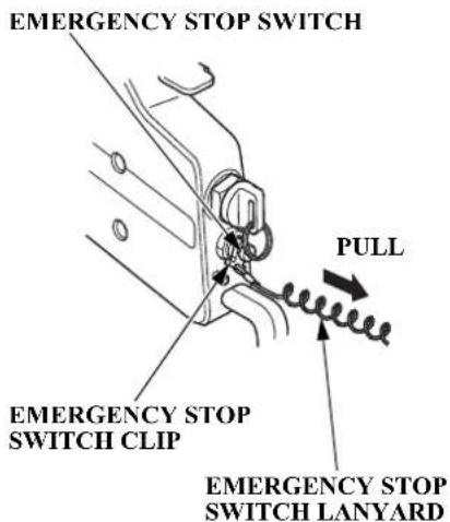
To stop the engine in an emergency, pull the emergency stop switch clip out of the emergency stop switch by pulling the emergency stop switch lanyard.
We suggest that you stop the engine this way occasionally to verify that the emergency stop switch is operating properly.
Turn the ignition switch key to the OFF position after verifying the emergency stop switch operation.
OPERATION
Normal Engine Stopping
LH and LHT Types (tiller handle)
LRT and XRT Types (remote control)
Side-Mount Control Type
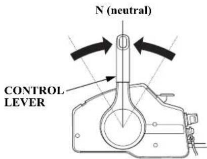
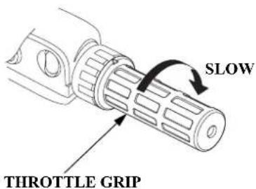
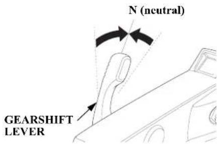
- Move the throttle grip to the slowest speed and the gearshift lever or control lever to the N (neutral) position.
After cruising at full throttle, cool down the engine by idling for a few minutes before stopping the engine.
OPERATION
LH and LHT Types (tiller handle)
LRT and XRT Types (remote control)
-
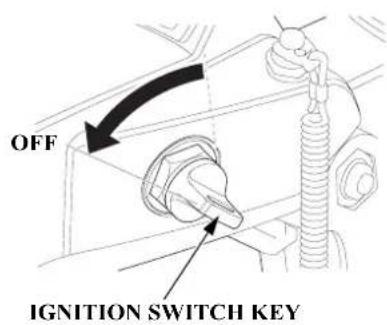
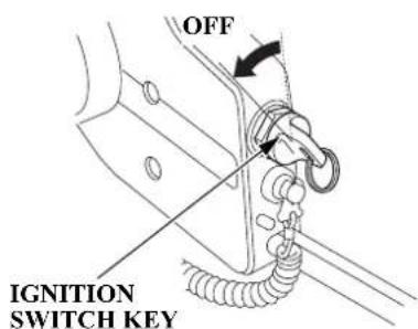
Turn the ignition switch key to the OFF position to stop the engine. In the event that the engine does not stop when the ignition switch key is turned to the OFF position, pull the emergency stop switch clip out of the emergency stop switch by pulling the emergency stop switch lanyard (p. 54).
-
When the boat is not in use, remove and store the ignition switch key and the emergency stop switch clip and lanyard. If you are using a portable fuel tank, disconnect the fuel hose if you will be storing or transporting the outboard motor.
GEARSHIFT AND THROTTLE OPERATION
LH and LHT Types (tiller handle)
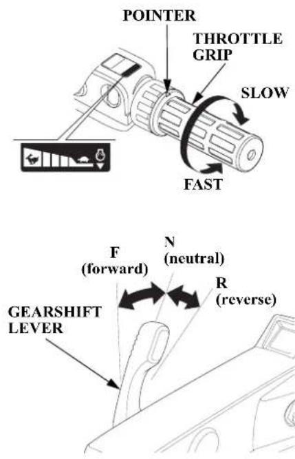
To shift gears, turn the throttle grip to the SLOW position; then move the gearshift lever to select the F (forward), N (neutral), or R (reverse) gears.
The engine can be started with the gearshift lever in the N (neutral) position only.
The throttle grip can be turned to the FAST position only when the gearshift lever is in the F (forward) position.
THROTTLE FRICTION ADJUSTER
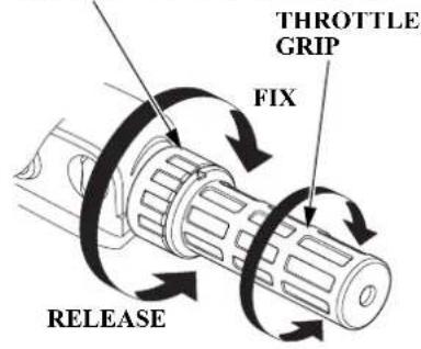
Use the throttle friction adjuster to help hold a constant throttle setting while cruising.
Turn the adjuster clockwise to increase throttle grip friction for holding a constant speed.
Turn the adjuster counterclockwise to decrease friction for easy grip rotation.
OPERATION
LRT and XRT Types (remote control)
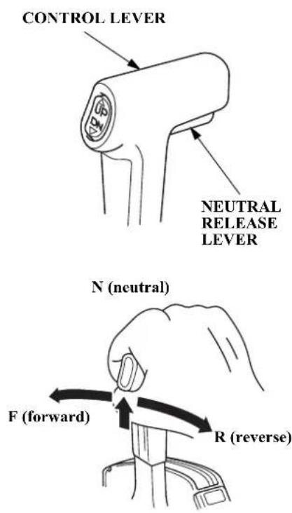
To shift gears, move the control lever to select the F (forward), N (neutral), or R (reverse) gear.
The control lever cannot be moved from the N (neutral) position unless the neutral release lever is squeezed.
Moving the control lever beyond the gear selection range increases engine speed.
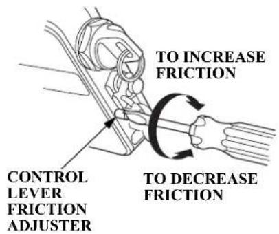
Adjust the control lever friction adjuster so the control lever will hold a constant throttle setting while cruising.
STEERING
LH and LHT Types (tiller handle)
RIGHT TURN LEFT TURN
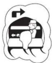
Move the tiller handle to the left.
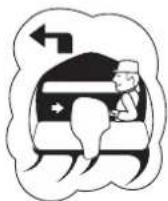
Move the tiller handle to the right.
Steer by moving the tiller handle opposite the direction you want the boat to turn.
Steering Friction Adjuster
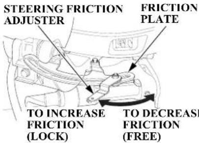
Use the steering friction adjuster to help hold a steady course while cruising.
Move the adjuster to the LOCK direction to increase steering friction for holding a steady course.
Move the adjuster to the FREE direction to decrease friction for easy turning.
NOTICE
Do not apply grease or oil on the friction plate. Grease or oil will reduce the friction of the adjuster.
LRT and XRT Types (remote control)
Steer the boat in the same manner as an automobile.
OPERATION
CRUISING
Engine Speed
For best fuel economy, limit the throttle opening to 80%. Use the throttle friction control (p. 57, 58) to help you hold a steady speed.
For rough water conditions or large waves, slow down to prevent the propeller from rising out of the water.
The engine is equipped with an overrev limiter to prevent the possibility of mechanical damage from excessive engine speed.
If, for example, the outboard motor is tilted excessively or propeller ventilation occurs during a sharp turn, the engine may overrev, activating the overrev limiter.
If engine speed becomes unstable at high speed due to activation of the overrev limiter, reduce speed and check the trim angle of the outboard motor.
Trim
LH Type
Install the outboard motor at the best trim angle for stable cruising and maximum power.
Trim angle too large: Causes boat to "squat."
Trim angle too small: Causes boat to "bow steer."
It is necessary to trim the angle of the outboard motor to compensate for changes in boat load, weight distribution, water conditions, or propeller selection.
Under normal conditions, the boat will perform best when the
antiventilation plate is level with the water surface.
When cruising into a high wind, trim the outboard motor down slightly to level the boat and improve stability. With a tail wind, trim the outboard motor up slightly.
LHT, LRT and XRT Types
Use the power trim/tilt switch to trim the outboard motor for the best performance and stability.
You can use the power trim/tilt switch at any time, whether the boat is underway or stopped.
Press the UP or DN (down) side of the switch to adjust the angle of the outboard motor.
Refer to the trim meter (p. 31) for an indication of whether the outboard motor is trimmed high or low.
OPERATION
It is necessary to trim the angle of the outboard motor to compensate for changes in boat load, weight distribution, water conditions, or propeller selection.
Under normal conditions, the boat will perform best when the antiventilation plate is level with the water surface.
When cruising into a high wind, trim the outboard motor down slightly to level the boat and improve stability. With a tail wind, trim the outboard motor up slightly.
NOTICE
Excessive trim/tilt angle during operation can cause propeller ventilation, overheating, and water pump damage. This type of damage is not covered by the Distributor's Limited Warranty (p. 124).
LHT Type
LRT and XRT Types
POWER TRIM/TILT SWITCH
Press UP to trim or tilt the outboard motor up.
Press DN to trim or tilt the outboard motor down.
CONTROL LEVER
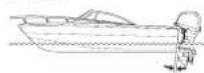
OUTBOARD MOTOR TRIMMED TOO LOW
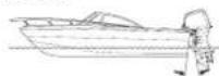
OUTBOARD MOTOR TRIMMED TOO HIGH
OUTBOARD MOTOR
TRIMMED CORRECTLY

BOW TOO LOW DUE TO
- LOAD IN THE FRONT
- OUTBOARD MOTOR TRIMMED TOO LOW
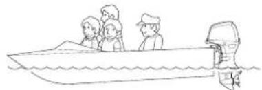
natural_image
Simple line drawing of a boat with passengers on deck and a speedboat nearby (no text or symbols)BOW TOO HIGH DUE TO
- LOAD IN THE REAR
- OUTBOARD MOTOR TRIMMED TOO HIGH
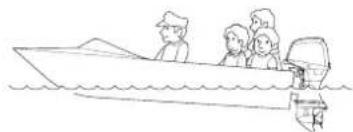
natural_image
Line drawing of a speedboat with passengers on water (no text or symbols)OPERATION
Trolling Speed Control [optional equipment (except LHA and LHTC types)]
SWITCH PANEL
![Honda BF40D (2014) - Trolling Speed Control [optional equipment (except LHA and LHTC types)] - 1](/content/2026/06/1277068/images/c17a85074797252482252f462408d4af86e642097c1c9c0405baf5f663b82a18.jpg)
flowchart
graph TD
    A["UP"] --> B["TRL"]
    B --> C["DN"]
    C --> D["Bottom Layer"]
    style A fill:#f9f,stroke:#333
    style B fill:#ccf,stroke:#333
    style C fill:#cfc,stroke:#333
    style D fill:#fcc,stroke:#333
TRL (Trolling) CONTROL SWITCH
DN: Reduce engine speed UP: Increase engine speed
Place the outboard motor in-gear with the throttle control in the fully closed (idle) position. Press and hold the UP or DN side of the TRL control switch to activate the Trolling Speed Control. The buzzer will make one long sound indicating activation. The initial trolling speed is set at 800 RPM.
The engine speed can be adjusted in 50 RPM increments by pressing the UP or DN side of the TRL control switch. A short sound of the buzzer occurs each time the engine speed is adjusted.
In Trolling Speed Control mode, the engine speed can be adjusted between 800 and 1,100 RPM.
Continuing to press the switch when at either of these limits will result in two short sounds from the buzzer. The throttle control will operate when in the Trolling Speed Control mode, but once the speed reaches 3,000
RPM, the Trolling Speed Control is deactivated. If 3,000 RPM is not reached and the throttle is closed, the engine speed will decrease to the Trolling Speed Control setting.
TRIM TAB
If steering effort is not equal in both directions, adjust the trim tab to compensate for “torque steer,” which is the reaction of the outboard motor to propeller rotation.
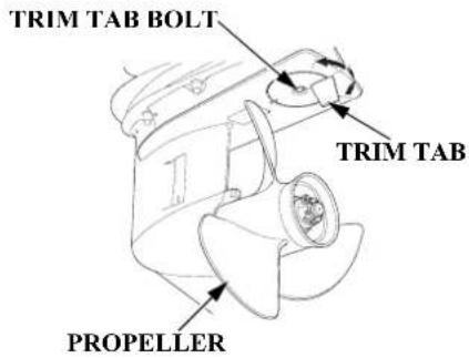
Adjust the trim tab with the engine stopped. Loosen the trim tab bolt above the trim tab, turn the trim tab, and then tighten the bolt securely.
When the trim tab is correctly adjusted, steering effort will be equal in both directions.
Refer to TRIM TAB ADJUSTMENT on p. 72.
LHT, LRT and XRT Types
When operating in shallow water, use the power trim/tilt switch (p. 61) to tilt the outboard motor so that the propeller and gear case won't hit the bottom.
Proceed at low speed, and monitor water flow from the cooling system indicator (p. 34) to be sure the outboard motor is not tilted so high that the water intakes are out of the water.
NOTICE
An excessive trim/tilt angle during operation can cause propeller ventilation, overheating, and water pump damage. This type of damage is not covered by the Distributor's Limited Warranty (p. 124).
LH Type
When operating in shallow water, tilt the outboard motor, using the tilt lever, so the propeller and gear case won't hit the bottom.
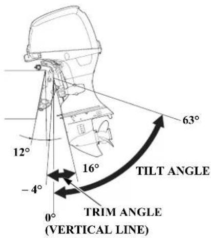
(when transom angle is 12°)
OPERATION
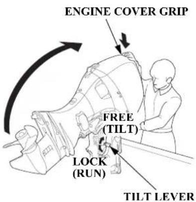
To tilt the outboard motor, move the tilt lever to the FREE (TILT) position, then raise the outboard motor to the desired position by pulling on the engine cover grip.
NOTICE
Do not use the tiller handle as a lever to raise the outboard motor. Applying excessive force to the tiller handle can damage it.
While the outboard motor is tilted, proceed at a low speed, and do not operate the outboard motor in reverse. The outboard motor will rise suddenly if operated in reverse.
Monitor water flow from the cooling system indicator (p. 34) to be sure the outboard motor is not tilted so high that the water intake is out of the water.
NOTICE
An excessive tilt angle during operation can cause propeller ventilation, overheating, and water pump damage. This type of damage is not covered by the Distributor's Limited Warranty (p. 124).
To return the outboard motor to the normal operating position, move the tilt lever to the LOCK (RUN) position. You may need to raise the outboard motor slightly to disengage the tilt mechanism, and then slowly lower the outboard motor.
MOORING, BEACHING, LAUNCHING
Before tilting up, leave the outboard motor in the running position for one minute after stopping the engine to drain the water from inside the engine.
Stop the engine and disconnect the fuel hose from the outboard motor before tilting the outboard motor.
LH Type
Use the tilt lever to raise and lower the outboard motor as described on p. 64.
LHT, LRT and XRT Types
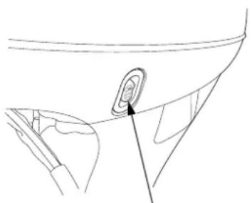
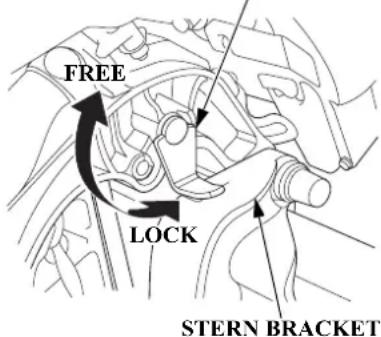
To raise the outboard motor out of the water while the engine is stopped and the boat is moored, or for maximum clearance when beaching or launching, use the power tilt switch on the engine pan to tilt the outboard motor up as far as it will go. Move the tilt lock lever to the LOCK position, and then gently lower the outboard motor until the lever contacts the stern bracket.
If more clearance is needed to swing the tilt lock lever into the LOCK position, rock the outboard motor forward slightly by pulling on the engine cover grip.
To lower the outboard motor, tilt up, move the tilt lock lever to the FREE position, and then lower the outboard motor to the desired position.
natural_image
Line drawing of a car interior showing a circular object with an arrow pointing to it (no text or symbols)POWER TILT SWITCH (LHT, LRT and XRT Types)
TILT LOCK LEVER
(lock position)
NOTICE
Do not attempt to use the power tilt switch to tilt the outboard motor down while the tilt lock lever is in the LOCK position. Damage to the power tilt system may occur.
OPERATION
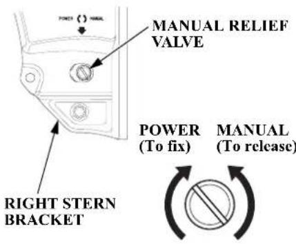
The outboard motor can also be tilted manually after opening the manual relief valve. This feature enables the outboard motor to be tilted up or down when no battery is connected.
For manual tilting, use a flat blade screwdriver to turn the valve counterclockwise 2 and a half turns. Close the valve firmly after positioning the engine.
Check that nobody is under the outboard motor before opening the manual relief valve. If the manual relief valve is loosened (turned counterclockwise) when the outboard motor is tilted up, the outboard motor will suddenly tilt down.
Be sure the valve is closed before operating the outboard motor. If the valve is not closed, the outboard motor will tilt up when operated in reverse.
MULTIPLE OUTBOARD MOTORS
On boats equipped with more than one outboard motor, all motors normally operate at the same time.
If one or more motor(s) is stopped while the other(s) is running, put the stopped motor in “N” (neutral) and tilt it up so its propeller is above the water's surface.
If the propeller of the stopped motor is left in the water, it may turn as the boat moves through the water, causing a reverse flow of water from the exhaust side. This reverse flow will happen if the stopped engine's propeller is in the water, its gearshift is in "R" (reverse), and the boat is moving forward. Reverse flow can cause an engine malfunction.
SERVICING YOUR OUTBOARD MOTOR
THE IMPORTANCE OF MAINTENANCE
Proper maintenance is essential for safe, economical, and trouble-free operation. It will also help reduce air pollution.
WARNING
Improperly maintaining this outboard motor or failure to correct a problem before operation can cause a malfunction in which you could be seriously hurt or killed.
Always follow the inspection and maintenance recommendations and schedules in this Owner's Manual.
To help you properly care for your outboard motor, the following pages include a maintenance schedule, routine inspection procedures, and simple maintenance procedures using basic hand tools. Other service tasks that are more difficult or require special tools are best handled by professionals and are normally performed by a Honda technician or other qualified mechanic.
The maintenance schedule applies to normal operating conditions. If you operate your outboard motor under unusual conditions, consult an authorized Honda Marine dealer for recommendations applicable to your individual needs and use.
Remember that your authorized Honda Marine dealer knows your outboard motor best and is fully equipped to maintain and repair it.
To ensure the best quality and reliability, use only new, Honda Genuine parts or their equivalents for repair and replacement.
Maintenance, replacement, or repair of the emission control devices and systems may be performed by any marine engine repair establishment or individual, using parts that are “certified” to EPA standards.
SERVICING YOUR OUTBOARD MOTOR
MAINTENANCE SAFETY
Some of the most important safety precautions follow. However, we cannot warn you of every conceivable hazard that can arise in performing maintenance. Only you can decide whether or not you should perform a given task.
WARNING
Failure to properly follow maintenance instructions and precautions can cause you to be seriously hurt or killed.
Always follow the procedures and precautions in the Owner's Manual.
Safety Precautions
- Make sure the engine is off before you begin any maintenance or repairs. This will eliminate several potential hazards:
— Carbon monoxide poisoning from engine exhaust.
Do not start or run the engine in a confined or partly enclosed area.
— Burns from hot parts.
Let the engine and exhaust system cool before touching.
— Injury from moving parts.
Do not run the engine unless instructed to do so.
- Read the instructions before you begin, and make sure you have the tools and skills required.
• To reduce the possibility of fire or explosion, be careful when working around gasoline. Use only a nonflammable solvent, not gasoline, to clean parts. Keep cigarettes, sparks, and flames away from all fuel-related parts. - Wear gloves when handling the propeller to protect your hands from sharp edges.
SERVICING YOUR OUTBOARD MOTOR
SPARE SWITCH CLIP (LH and LHT Types) AND EMERGENCY STARTER ROPE
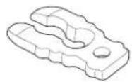
SPARE SWITCH CLIP (LH and LHT Types)
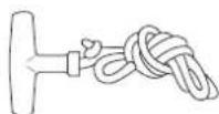
EMERGENCY STARTER ROPE
Always carry the spare switch clip and the emergency starter rope onboard. The spare clip may either be stored in the tool bag or in an easily accessible location on the boat along with the emergency starter rope.
TOOL KIT and OWNER'S MANUAL
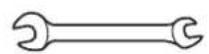
8 × 10 mm WRENCH

FLAT SCREWDRIVER
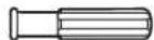
GRIP
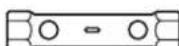
18×19mm
SOCKET WRENCH
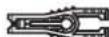
FUSE PULLER
natural_image
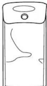
Simple line drawing of a rectangular container with a lid and internal curved lines (no text or symbols)TOOL BAG
natural_image
Simple line drawing of a rectangular frame with curved lines inside, no text or symbols present.OWNER'S MANUAL
The owner's manual and tool kit can be used to perform simple maintenance procedures and emergency repairs. Keep these items on the boat so that they will always be available if you need them.
If your tool kit needs replacement, it is not available as a kit and each item must be ordered individually.
SERVICING YOUR OUTBOARD MOTOR
MAINTENANCE SCHEDULE
Follow the MAINTENANCE SCHEDULE table and service your outboard motor accordingly. Please note, a claim for warranty coverage will not be denied simply because the maintenance schedule for your outboard motor was not followed. However, any part(s) that fails specifically due to lack of maintenance, or improperly performed maintenance, would not be covered under the Distributor's Limited Warranty.
| REGULAR SERVICE PERIOD (3)Perform at every indicated month or operating hour interval, whichever comes first. | Each use After use | First month or 20 hrs. | Every 6 months or 100 hrs. | Every year or 200 hrs. | Every 2 years or 400 hrs. | Refer to page | |
| ITEM | |||||||
| Engine oil Check level o 74 | |||||||
| Change o o 76 | |||||||
| Gear case oil | Change | o (2) | o (2) | — | |||
| Engine oil filter | Replace | o (2) | — | ||||
| Timing belt | Check-adjust | o (2) | — | ||||
| Throttle linkage | Check-adjust | o (2) | o (2) | — | |||
| Idling speed | Check-adjust | o (2) | o (2) | — | |||
| Valve clearance | Check-adjust | o (2) | — | ||||
| Spark plug | Check-adjust/Replace | o | 78 – 79 | ||||
| Propeller and cotter pin | Check | o | 89 | ||||
| Anode metal (Outside engine) | Check | o | 88 | ||||
| Anode metal (Inside engine) | Check | o (2) | — | ||||
| Lubrication | Grease | o (1) | o (1) | 80 | |||
| Fuel tank and tank filter | Clean | o | 87 | ||||
| Thermostat | Check | o (2) | — | ||||
(1) Lubricate more frequently when used in salt water.
(2) These items should be serviced by your servicing dealer, unless you have the proper tools and are mechanically proficient. Refer to the Honda shop manual for service procedures. See “Honda Publications” on page 121 for ordering information.
(3) For professional commercial use, log hours of operation to determine proper maintenance intervals.
SERVICING YOUR OUTBOARD MOTOR
| REGULAR SERVICE PERIOD (3)Perform at every indicated month or operating hour interval, whichever comes first. | Each use After use | First month or 20 hrs. | Every 6 months or 100 hrs. | Every year or 200 hrs. | Every 2 years or 400 hrs. | Refer to page | |
| ITEM | |||||||
| Fuel filter(Low pressure side) | Check | o (5) | o | 84 – 87 | |||
| Replace o | |||||||
| Fuel filter(High pressure side) | Check o (2) | — | |||||
| Replace o (2) | |||||||
| Fuel line Check o (7) | — | ||||||
| Replace Every 2 years (If necessary) (2) (8) | |||||||
| Battery and cable connection Check level-tightness o — | |||||||
| Bolts and nuts | Check-tightness | o (2) | o (2) | — | |||
| Crankcase breather tube | Check | o (2) | — | ||||
| Cooling water passages | Clean | o (4) | — | ||||
| Water pump | Check | o (2) | — | ||||
| Emergency stop switch | Check | o | 39 | ||||
| Engine oil leak | Check | o | — | ||||
| Each operation part | Check | o | — | ||||
| Engine condition (6) | Check | o | — | ||||
| Power Trim/Tilt | Check | o (2) | — | ||||
| Shift Cable | Check-adjust | o (2) | — | ||||
(1) Lubricate more frequently when used in salt water.
(2) These items should be serviced by your servicing dealer, unless you have the proper tools and are mechanically proficient. Refer to the Honda shop manual for service procedures. See “Honda Publications” on page 121 for ordering information.
(3) For professional commercial use, log hours of operation to determine proper maintenance intervals.
(4) When operating in salt water, turbid or muddy water, the engine should be flushed with clean water after each use.
(5) Check for water and contamination.
(6) Upon starting, check for unusual engine sounds and cooling water flowing freely from the check hole.
(7) Check the fuel line for leaks, cracks or damage. If it is leaking, cracked or damaged, take it to your servicing dealer for replacement before using your outboard.
(8) Replace the fuel line if there are signs of leaks, cracks or damage.
SERVICING YOUR OUTBOARD MOTOR
TRIM TAB ADJUSTMENT
The trim tab compensates for “torque steer,” which is a reaction of the outboard motor to propeller rotation.
If uncompensated, torque steer would make the outboard motor tend to turn to one side.
When the trim tab is correctly adjusted, steering effort is equal in either direction.
If steering effort is unequal, loosen the trim tab bolt and adjust the angle of the trim tab. Retighten the trim tab bolt securely.
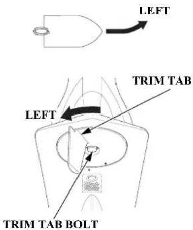
If less effort is required to make left turns, move the back of the trim tab left.
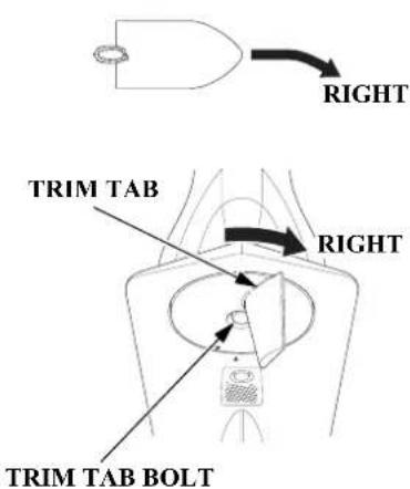
If less effort is required to make right turns, move the back of the trim tab right.
Adjust the trim tab in small increments, and retest steering effort with the boat evenly loaded and running at cruising speed.
MANUAL RELIEF VALVE
LHT, LRT and XRT Types
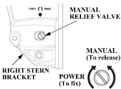
The outboard motor can be tilted manually after opening the manual relief valve. This feature enables the outboard motor to be tilted up or down when no battery is connected.
For manual tilting, use a flat blade screwdriver to turn the valve counterclockwise 2 and a half turns. Close the valve firmly after positioning the engine.
Check that nobody is under the outboard motor before opening the manual relief valve. If the manual relief valve is loosened (turned counterclockwise) when the outboard motor is tilted up, the outboard motor will suddenly tilt down.
Be sure the valve is closed before operating the outboard motor. If the valve is not closed, the outboard motor will tilt up when operated in reverse.
ENGINE COVER REMOVAL AND INSTALLATION
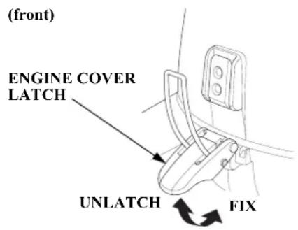
(rear)
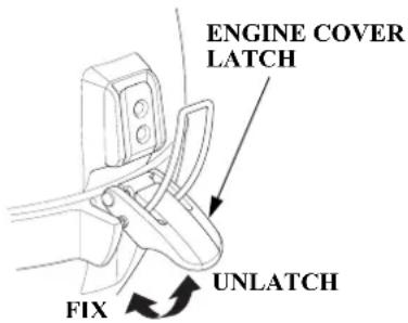
The engine cover latches fasten the engine cover to the outboard motor.
To remove the engine cover, unlatch both front and rear latches, then lift the engine cover off the outboard motor.
To install the engine cover, place the cover on the outboard motor, then latch both front and rear latches securely.
SERVICING YOUR OUTBOARD MOTOR
Engine Oil Level Check
Check the engine oil level with the engine stopped and the outboard motor in the vertical position.
- Unlatch and remove the engine cover (p. 73).
- Remove the oil level dipstick and wipe it clean.
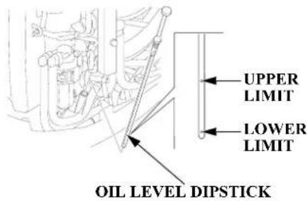
- Insert the dipstick all the way in, then remove it and check the oil level shown on the dipstick.
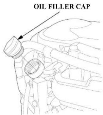
- If the oil level is low, remove the oil filler cap, and add oil to reach the upper limit mark shown on the dipstick. Use the oil recommended on p. 78.
NOTICE
Running the engine with a low oil level can cause engine damage.
- Install the oil filler cap and tighten it securely.
- Install and lock the engine cover.
SERVICING YOUR OUTBOARD MOTOR
When you check the oil level with the dipstick, you might notice the engine oil appears milky or the oil level has increased. If you notice either condition, change the engine oil. See the following table for an explanation of these conditions.
| Operating Method Result Effect | ||
| Running the engine below 3,000 rpm for more than 30% of the time so the engine does not warm up. | • Water condenses in the engine and mixes with the oil, resulting in a milky appearance. | The engine oil deteriorates, becomes less efficient as a lubricant, and causes an engine malfunction. |
| Frequent starting and stopping without allowing the engine to warm up. | • Unburned fuel mixes with the oil, increasing the volume of oil. | |
SERVICING YOUR OUTBOARD MOTOR
Engine Oil Change
An engine oil evacuation device may be used to remove the engine oil.
Drain the used oil while the engine is warm. Warm oil drains quickly and completely.
- Unlatch and remove the engine cover (p. 73). Remove the oil filler cap (p. 74).
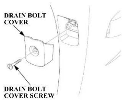
- Loosen the drain bolt cover screw using a flat blade screwdriver and remove the drain bolt cover.
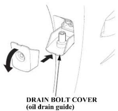
- Place the drain bolt cover as shown to use it as an oil drain guide. Place a suitable container under the guide.
SERVICING YOUR OUTBOARD MOTOR
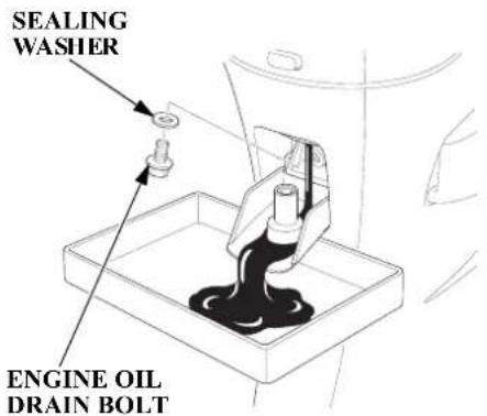
- Remove the engine oil drain bolt and sealing washer.
- Allow the used oil to drain completely, then install a new sealing washer on the engine oil drain bolt, and tighten it securely.
- Reinstall the drain bolt cover.
NOTICE
Improper disposal of engine oil can be harmful to the environment. If you change your own oil, please dispose of the used oil properly. Put it in a sealed container, and take it to a recycling center. Do not discard it in a trash bin, dump it on the ground, or pour it down a drain.
- With the outboard motor in a vertical position, fill to the upper limit mark on the dipstick (p. 74) with the recommended oil.
Engine oil refill capacity:
Without oil filter change:
2.1 US qt (2.0 L)
With oil filter change:
2.2 US qt (2.1 L)
- Install the oil filler cap and tighten it securely.
- Install and lock the engine cover.
SERVICING YOUR OUTBOARD MOTOR
Engine Oil Recommendations
Oil is a major factor affecting performance and service life. Use 4-stroke detergent oil.
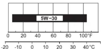
SAE 5W-30 is recommended for general use.
Honda recommends that you use API service category SG, SH or SJ oil. The SAE oil viscosity and service category are in the API label on the oil container.
Spark Plug Service
RECOMMENDED SPARK PLUGS: DR7EB (NGK) X22 ESR-UB (DENSO)
NOTICE
Incorrect spark plugs can cause engine damage.
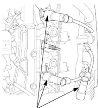
- Unlatch and remove the engine cover (p. 73).
natural_image
Technical line drawing of mechanical components with no visible text or symbolsSPARK PLUG CAPS
SPARK PLUG WRENCH
natural_image
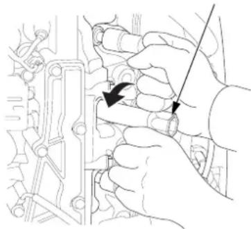
Line drawing of hands performing a mechanical tool on a vehicle engine (no text or symbols)-
Disconnect the spark plug caps from the spark plugs.
-
Remove the spark plugs with a spark plug wrench.
SERVICING YOUR OUTBOARD MOTOR
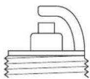
New plug
Plug needing replacement
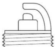
- Inspect the spark plugs. Replace them if the electrodes are worn, or if the insulators are cracked or chipped.
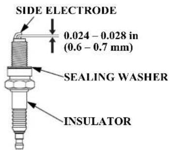
- Measure the spark plug electrode gap with a wire-type feeler gauge. Correct the gap, if necessary, by carefully bending the side electrode.
The gap should be: 0.024 - 0.028 in (0.6 - 0.7 mm)
-
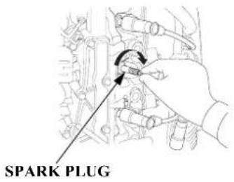
Install the spark plugs carefully, by hand, to avoid cross-threading.
-
After each spark plug seats, tighten with a spark plug wrench to compress the sealing washer.
If reinstalling used spark plugs, tighten 1/8 - 1/4 turn after the spark plugs seat.
If installing new spark plugs, tighten 1/2 turn after the spark plugs seat.
NOTICE
Loose spark plugs can overheat and damage the engine.
Overtightening the spark plugs can damage the threads in the cylinder head.
-
Attach the spark plug caps.
-
Install and lock the engine cover.
SERVICING YOUR OUTBOARD MOTOR
Lubrication Points
Apply Honda Marine waterproof grease to the parts shown below:
Lubrication interval:
After the first 20 hours or 1 month, then every 100 hours or 6 months (refer to the maintenance schedule on page 70).
NOTICE
To prevent corrosion, apply anticorrosion oil to pivot surfaces where grease cannot penetrate.
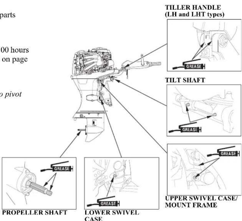
Apply Honda Marine Corrosion Inhibitor (or equivalent) to all areas under the engine cover and any exposed metal surfaces except the belts.
SERVICING YOUR OUTBOARD MOTOR
REFUELING
If you do not anticipate cycling through at least one complete tank of fuel within a 30 day period, we recommend adding Honda Marine Fuel Stabilizer each time you refuel.
Portable Fuel Tank [standard equipment (Canadian types)] [optional equipment (American types)]
FUEL TANK CAPACITY: 6.6 US gal (25 L)
Check the fuel gauge and refill the tank when necessary.
Remove the fuel tank from the boat for refueling.
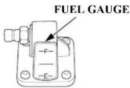
- Turn the vent knob counterclockwise all the way to open the vent.
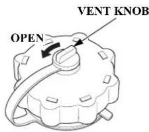
- Turn the fuel filler cap counterclockwise so that it touches the pressure relief tab.
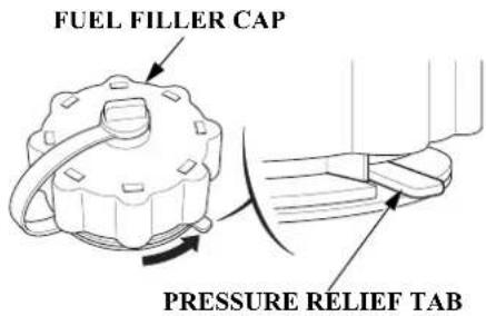
- Press down the pressure relief tab, and then turn the fuel filler cap 1/4 counterclockwise. Release the pressure relief tab. Wait to relieve pressure.
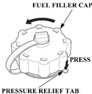
- The fuel filler cap will lock again. Press down the pressure relief tab, and turn counterclockwise to remove the fuel filler cap.
SERVICING YOUR OUTBOARD MOTOR
SAFE FILL LEVEL
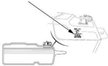
Refuel in a well-ventilated area. Fill the tank to the SAFE FILL LEVEL line.
After refueling, install the cap and tighten it until you hear it click. Close the vent by turning the vent knob clockwise all the way, and return the fuel tank to the boat.
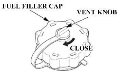
Using the fuel tank mounted in the boat.
Check the fuel level and refill if necessary. Do not fill the fuel tank above the UPPER LIMIT. Refer to the boat manufacturer's instructions.
NOTICE
Fuel can damage paint and plastic. Be careful not to spill fuel when filling your fuel tank. Damage caused by spilled fuel is not covered under warranty.
WARNING
Gasoline is highly flammable and explosive.
You can be burned or seriously injured when handling fuel.
- Stop the engine and keep heat, sparks, and flame away.
- Handle fuel only outdoors.
- Wipe up spills immediately.
Never refill the fuel tank inside a building where gasoline fumes may reach flames or sparks. Keep gasoline away from appliance pilot lights, barbecues, electric appliances, power tools, etc.
Spilled fuel is not only a fire hazard, it causes environmental damage. Wipe up spills immediately.
SERVICING YOUR OUTBOARD MOTOR
FUEL RECOMMENDATIONS
Use unleaded gasoline with a pump octane rating of 86 or higher.
Your outboard motor is certified to operate on unleaded gasoline. Unleaded gasoline produces fewer engine and spark plug deposits and extends exhaust system life.
Never use stale or contaminated gasoline or an oil/gasoline mixture. Avoid getting dirt or water in the fuel tank.
You may use unleaded gasoline containing no more than 10% ethanol (E10) or 5% methanol by volume. In addition, methanol must contain cosolvents and corrosion inhibitors.
Use of fuels with content of ethanol or methanol greater than shown above may cause starting and/or performance problems. It may also damage metal, rubber, and plastic parts of the fuel system.
Engine damage or performance problems that result from using a fuel with percentages of ethanol or methanol greater than shown above are not covered under warranty.
If your outboard motor will be used on an infrequent or intermittent basis, please refer to the fuel section of the STORAGE chapter (p. 94) for additional information regarding fuel deterioration.
SERVICING YOUR OUTBOARD MOTOR
Fuel Filter/Water Separator Inspection and Service
The fuel filter is located under the engine cover between the fuel coupling and the fuel pump.
Water or sediment accumulation in the filter can cause loss of power or hard starting. To prevent engine malfunction, inspect the filter and replace when necessary.
A red ring float is located inside the strainer cup. It floats on top of the water and indicates how much water has accumulated in the strainer cup.
WARNING
Gasoline is highly flammable and explosive.
You can be burned or seriously injured when handling fuel.
- Stop the engine and keep heat, sparks, and flame away.
- Handle fuel only outdoors.
- Wipe up spills immediately.
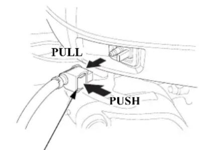
FUEL HOSE CONNECTOR
- Remove the engine cover (p. 73) and disconnect the fuel hose connector from the outboard motor.
SERVICING YOUR OUTBOARD MOTOR
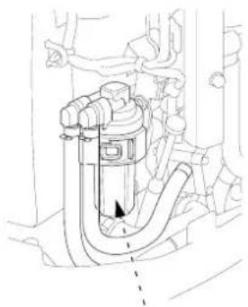
natural_image
Technical line drawing of a mechanical component with no visible text or symbolsFUEL FILTER (inside strainer cup)
- Inspect the filter for water and/or sediment accumulation.
If water and/or sediment are present, clean the strainer cup and filter or replace the filter as described in the following steps. Always replace the filter at the scheduled replacement interval (p. 71).
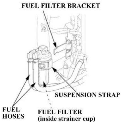
-
Remove the suspension strap from the fuel filter bracket, and then remove the strap from the fuel filter assembly.
-
Place commercially available hose clips on the fuel hoses on each side of the filter to prevent fuel leakage when the fuel hoses are disconnected.
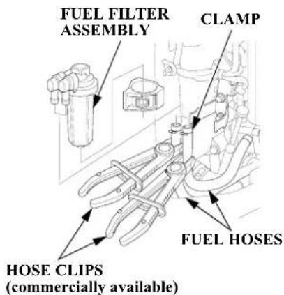
- Disconnect the fuel tubes from the fuel filter assembly.
SERVICING YOUR OUTBOARD MOTOR
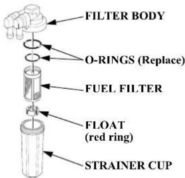
- Unscrew the strainer cup from the filter body.
-
Thoroughly clean the strainer cup and fuel filter. If the fuel filter is contaminated, replace it with a new one.
-
Install the fuel filter, float, O-rings and strainer cup. Use new O-rings.
TIGHTENING TORQUE: 2.2 lbf·ft (3 N·m, 0.3 kgf·m)
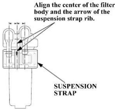
- Install the suspension strap to the fuel filter assembly as shown above.
-
Reinstall the fuel filter assembly and suspension strap in the reverse order of removal.
-
Connect the fuel hoses to the fuel filter securely with the hose clamps. Remove the fuel hose clips used to close the fuel hoses.
- Securely connect the fuel hose connector to the outboard motor (refer to page 43).
- Prime the engine using the priming bulb (p. 44). Check for fuel leaks. Repair any fuel leaks if necessary.
- Install and lock the engine cover.
If loss of power or hard starting are found to be caused by excessive water or sediment accumulation in the fuel filter, inspect the fuel tank.
Clean the fuel tank and tank filter if necessary. It may be necessary to drain the fuel tank completely and refill with fresh gasoline.
Portable Fuel Tank and Tank Filter Cleaning [standard equipment (Canadian types)] [optional equipment (American types)]
WARNING
Gasoline is highly flammable and explosive.
You can be burned or seriously injured when handling fuel.
- Stop the engine and keep heat, sparks, and flame away.
- Handle fuel only outdoors.
- Wipe up spills immediately.
Fuel Tank
FUEL HOSE
(standard equipment)
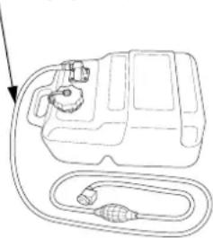
natural_image
Line drawing of a car fuel pump with attached hoses and valve (no text or symbols)Empty the portable fuel tank into an approved gasoline container. Use a funnel to avoid spilling fuel. Rinse the fuel tank with nonflammable solvent to remove any accumulated sediment.
SERVICING YOUR OUTBOARD MOTOR
Fuel Tank Filter
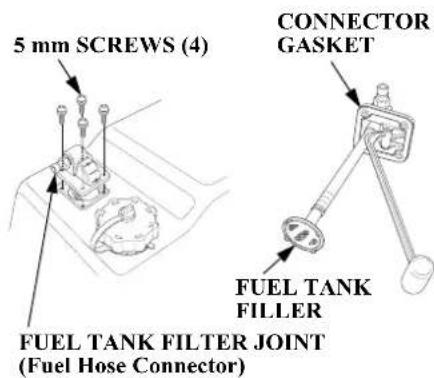
- Remove the four 5 mm screws using a flat screwdriver, then remove the fuel hose connector and fuel tank filter from the tank.
- Clean the filter in nonflammable solvent. Inspect the fuel tank filter and the connector gasket. Replace them if damaged.
- Reinstall the filter and hose connector in the fuel tank. Tighten the four 5 mm screws securely.
Anode Replacement
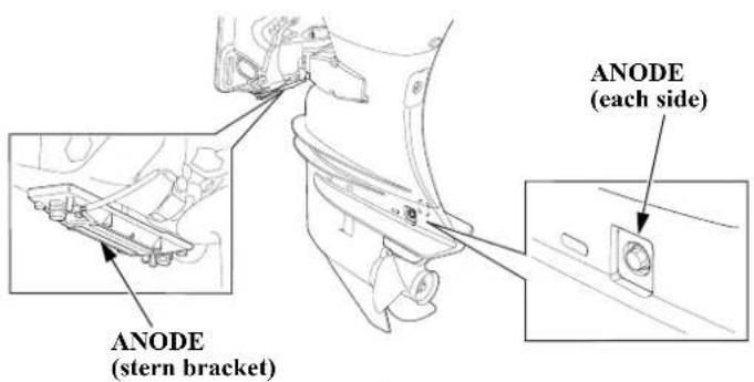
The anodes are located on each side of the gear case and on the stern bracket. They are made of a sacrificial material that helps to protect the outboard motor from corrosion.
Replace the anodes when they have been reduced to about half their original size, or if they are crumbling.
NOTICE
Painting or coating the anodes will def eat their purpose and will lead to rust and corrosion damage to the outboard motor. The anodes must be exposed to the water in order to protect the outboard motor.
Propeller Replacement [standard equipment (Canadian types)] [optional equipment (American types)]
Before replacing the propeller, remove the emergency stop switch clip from the emergency stop switch to prevent any possibility of the engine being started while you are working with the propeller. The propeller blades may have sharp edges, so wear heavy gloves to protect your hands.
Operating the outboard motor at higher altitudes will reduce available power. This may require decreasing the propeller pitch to maintain correct engine RPM.
Removal
-
Remove the cotter pin, unscrew the castle nut, remove the washer, and then remove the propeller and thrust washer.
-
Inspect the propeller shaft for any fishing line or debris.
Installation
- Apply marine grade grease to the propeller shaft.
- Install the thrust washer with the grooved side toward the gear case.
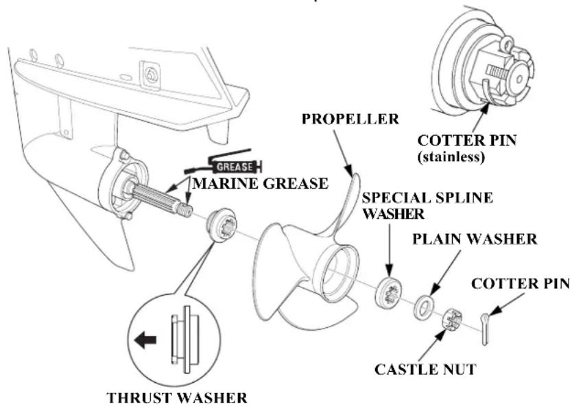
SERVICING YOUR OUTBOARD MOTOR
- Install the propeller, the special spline washer and the plain washer.
- Lightly tighten the castle nut by hand or wrench until the propeller has no free play.
- Tighten the castle nut using a torque wrench. CASTLE NUT TIGHTENING TORQUE: 0.7 lbf·ft (1 N·m, 0.1 kgf·m)
- Then, using a torque wrench, tighten the castle nut until the first available groove in the castle nut aligns with the cotter pin hole. Do not tighten past the first alignment of the castle nut groove and the cotter pin hole.
NOTICE
TIGHTENING TORQUE LIMIT: 25 lbf·ft (35 N·m, 3.5 kgf·m) Do not tighten the castle nut above the TIGHTENING TORQUE LIMIT, or the propeller and shaft may be damaged.
- Be sure to replace the cotter pin with a new one.
- Use a Honda Genuine stainless steel cotter pin or equivalent cotter pin and bend the pin ends as shown.
Note that these wrenches are not included with the tool set that comes with the outboard motor. Contact your authorized Honda Marine dealer for additional tool information.
CLEANING AND FLUSHING
Cleaning and Flushing
After each use in salt water or dirty water, thoroughly clean and flush the outboard motor with fresh water.
Touch up any damaged paint, and coat areas that may rust with Honda Corrosion Inhibitor, or equivalent. Lubricate controls with a silicone spray lubricant.
NOTICE
Do not apply water or corrosion inhibitor directly to the electrical components under the engine cover, such as the HO2 sensor and timing belt. If water or corrosion inhibitor penetrates these components, they may be damaged. Before applying a corrosion inhibitor, cover the HO2 sensor and timing belt with a protective material to prevent damage.
Cleaning
Wash the outside of the outboard motor with clean, fresh water, and flush the cooling system as follows.
Flushing With a Garden Hose Garden Hose Adapter (optional equipment)
It is necessary to run the engine during the flushing procedure. For safety, remove the propeller from the outboard motor (p. 89).
- Tilt down the outboard motor.
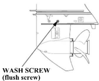
- Remove the wash screw and sealing washer from the WASH screw hole in the gear case. Be sure not to remove the oil level screw from the OIL LEVEL screw hole in the gear case.
CLEANING AND FLUSHING
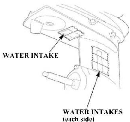
- Cover the three water intakes with duct tape as shown above.
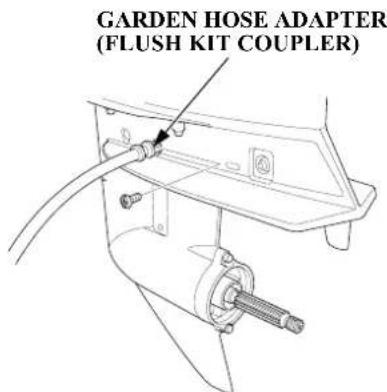
- Remove the sealing washer from the wash screw and install the sealing washer on the flush kit coupler.
-
Install the flush kit coupler into the WASH screw hole and connect a fresh water hose to the garden hose adapter.
-
Move the gearshift lever or control lever to the N (neutral) position. Flush the outboard motor in the neutral position only.
- Turn on the fresh water supply to the flush kit coupler.
NOTICE
Running the engine without good water circulation can cause overheating and water pump damage.
Damage caused by running the outboard motor without sufficient cooling water is not covered by the Distributor's Limited Warranty (p. 124).
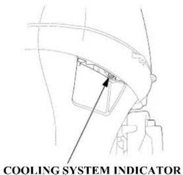
-
Start the engine. Monitor the cooling system indicator. Stop the engine if water does not come out of the cooling system indicator and check the fresh water supply.
-
Allow the engine to run at idle for at least 5 minutes to clean the inside of the outboard motor.
-
Stop the engine, and disconnect the fuel hose from the outboard motor. Remove the garden hose adapter.
-
Remove the sealing washer from the garden hose adapter and install the sealing washer on the wash screw.
If tape was used to cover the three water intakes in step 3, remove the tape now.
-
Install the wash screw into the gear case securely.
-
Tilt up the outboard motor and move the tilt lock lever to the LOCK position.
STORAGE
Fuel
NOTICE
Depending on the region where you operate your outboard, fuel formulations may deteriorate and oxidize rapidly. Fuel deterioration and oxidation can occur in as little as 15 days and may cause damage to the fuel system. Please check with your servicing dealer for local storage recommendations.
Gasoline will oxidize and deteriorate in storage. Old gasoline will cause hard starting, and it leaves gum deposits that clog the fuel system. If the gasoline in your fuel tank and vapor separator deteriorates during storage, you may need to have the vapor separator and other fuel system components serviced or replaced.
The length of time that gasoline can be left in your fuel tank and vapor separator without causing functional problems will vary with such factors as gasoline blend, your storage temperatures, and whether the fuel tank is partially or completely filled. The air in a partially filled fuel tank promotes fuel deterioration. Very warm storage temperatures accelerate fuel deterioration. Fuel deterioration problems may occur in less than 15 days, if the gasoline was not fresh when you filled the fuel tank.
You can extend fuel storage life by adding a gasoline stabilizer that is formulated for that purpose, or you can avoid fuel deterioration problems by draining all the fuel from the fuel tank and vapor separator.
The Distributor's Limited Warranty does not cover fuel system damage or engine performance problems resulting from neglected storage preparation.
Adding a Fuel Stabilizer
When adding a fuel stabilizer, fill the fuel tank with fresh gasoline. If only partially filled, air in the tank will promote fuel deterioration during storage. If you keep an additional container of gasoline for refueling, be sure that it contains only fresh gasoline.
- Drain the vapor separator before adding fuel stabilizer.
- Add Honda Marine fuel stabilizer following the instructions on the label.
- After adding a fuel stabilizer, run the engine in water for 10 minutes to be sure that the treated gasoline has replaced the untreated gasoline in the vapor separator.
- Turn the engine OFF.
Draining the Fuel System
You can avoid fuel deterioration problems by draining the fuel tank and vapor separator. Before draining and checking the fuel system, check the fuel filter for contamination and/or water accumulation. The fuel filter must be free of any contamination before proceeding (p. 84). Draining the vapor separator will not drain the fuel filter bowl.
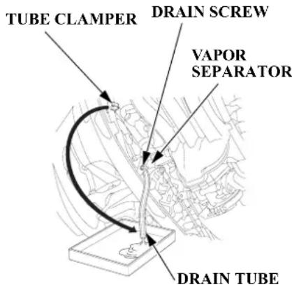
- Disconnect the fuel hose connector from the outboard motor (p. 84).
- Remove the engine cover (p. 73).
- Release the drain tube from its clamp along the high pressure fuel hose and set the end of the tube toward the outside of the engine undercase. Place an approved gasoline container below the end of the tube, and use a funnel to avoid spilling gasoline.
- Loosen the vapor separator drain screw.
WARNING
Gasoline is highly flammable and explosive.
You can be burned or seriously injured when handling fuel.
- Stop the engine and keep heat, sparks, and flame away.
- Handle fuel only outdoors.
- Wipe up spills immediately.
STORAGE
- Tilt the outboard motor up until gasoline flows out of the drain tube.
- Leave it in that position until the gasoline stops flowing.
-
After thoroughly draining, tighten the drain screw securely.
-
Check the drained gasoline for the presence of water or contamination. If either is present, you will have to reassemble and run the outboard to refill the vapor separator with gasoline and then drain it again. Repeat the following procedure until no water or contamination is present in the removed gasoline.
a. Make sure the gasoline supply is not contaminated.
b. Reassemble the outboard and reconnect the fuel line connector.
c. Place the outboard in water. Use the priming bulb to refill the fuel system and run the outboard at idle for 3 minutes.
d. Stop the outboard and follow the procedure beginning with step 1 above.
- Secure the drain tube to the clamp along the high pressure fuel hose.
- Install the engine cover.
- Drain the fuel tank into an approved gasoline container, or if you need to store fuel in the fuel tank, you can extend fuel storage life by filling the fuel tank with fresh gasoline and adding Honda Marine fuel stabilizer following the directions on the container. Close the fuel cap vent.
If using the portable fuel tank, close the fuel filler cap vent knob. Store the portable fuel tank in a cool dry place out of direct sunlight.
Engine Oil
- Change the engine oil (p. 76).
- Remove the spark plugs (p. 78), and remove the emergency stop switch clip from the emergency stop switch.
- Pour 1 - 2 teaspoons (5 - 10 cm ^3 ) (p. 111) of clean engine oil into each cylinder.
- Using the emergency starter rope (p. 52), rotate the flywheel a few revolutions to distribute the oil in the cylinders.
- Reinstall the spark plugs (p. 79).
HOISTING THE OUTBOARD MOTOR
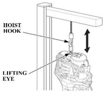
- Unlatch and remove the engine cover (p. 73).
- Attach the hoist hook to the lifting eye.
-
Disconnect the outboard motor from the boat, hoist the outboard motor, and move it to the storage area.
-
After the outboard motor is placed in storage and disconnected from the hoist, install the engine cover.
STORAGE PRECAUTIONS
Select a well-ventilated storage area. If possible, avoid storage areas with high humidity.
If storing a container of gasoline, such as the portable fuel tank (standard or optional equipment), store it away from any appliance that operates with a flame, such as a furnace, water heater, or clothes dryer. Also avoid any area with a spark producing electric motor, or where power tools are operated.
STORAGE
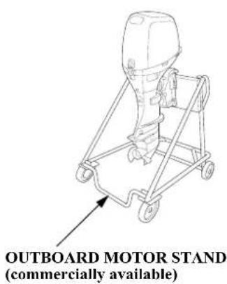
If the outboard motor will be removed from the boat for storage, we recommend storing it vertically by mounting it on a commercially available stand.
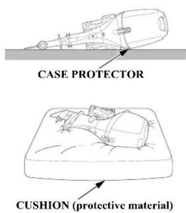
If it is necessary to store the outboard motor horizontally as shown, drain the vapor separator (p. 95), and drain the engine oil (p. 76), before removing the outboard motor from the boat.
Position the outboard motor with its case protector side down, and rest the outboard motor on a cushion of protective material.
NOTICE
Any other horizontal storage position may cause damage to the outboard motor or oil leakage.
Cover the outboard motor to keep out dust. Do not use plastic sheet as a dust cover. A nonporous cover will trap moisture, promoting rust and corrosion.
REMOVAL FROM STORAGE
Check your outboard motor as described in the BEFORE OPERATION chapter of this manual.
If the cylinders were coated with oil during storage preparation, the engine may smoke briefly at startup. This is normal.
TRANSPORTING
WITH OUTBOARD MOTOR INSTALLED ON BOAT
When trailering a boat with the outboard motor attached, always disconnect the fuel line from the portable fuel tank.
LH and LHT Types (tiller handle)
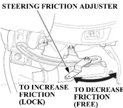
Tighten the steering friction adjuster to prevent the outboard motor from moving while trailing the boat.
LRT and XRT Types (remote control)
Use an outboard motor support bar to prevent the outboard motor from moving while trailering the boat. Refer to the manufacturer's instructions for using an outboard motor support bar.
All Types
The preferred method is to leave the engine in the normal running position, but if there is insufficient road clearance, you can tilt the outboard motor using a commercially available outboard motor support bar available through your dealer. Refer to the manufacturer's instructions for using an outboard motor support bar.
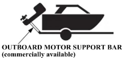
WITH OUTBOARD MOTOR REMOVED FROM BOAT
Secure the outboard motor in either the vertical or horizontal position shown on p. 98.
TAKING CARE OF UNEXPECTED PROBLEMS
ENGINE WILL NOT START
| Possible Cause Correction | |
| Clip not inserted in emergency stop switch. Insert clip in emergency stop switch. | |
| Gearshift lever or control lever not in neutral position. | Shift to neutral (p. 45 or 48). |
| Throttle grip not in START position (tiller handle type). | Turn throttle lever or grip to START position (p. 46). |
| Fast idle lever raised (remote control/side-mount type). | Leave fast idle lever in the START position (p. 49). |
TAKING CARE OF UNEXPECTED PROBLEMS
ENGINE WILL NOT START
| Possible Cause Correction | |
| Out of fuel. Refuel (p. 81). | |
| Fuel vent closed (portable fuel tank). | Open fuel filler cap vent (p. 36). |
| Fuel hose not primed. | Squeeze priming bulb (p. 44). |
| Fuel filter or fuel tank filter clogged. | Replace fuel filters (p. 84 and 88). |
| Bad fuel; outboard motor stored without treating or draining gasoline, or refueled with bad gasoline. | Drain fuel tank and vapor separator (p. 95). Refill with fresh gasoline (p. 81). |
TAKING CARE OF UNEXPECTED PROBLEMS
ENGINE WILL NOT START
| Possible Cause Correction | |
| Battery connections loose or corroded. | Clean and tighten battery connections. |
| Battery discharged. Recharge battery. | |
| Fuse(s) blown. | Replace fuse(s) (p. 105). |
| Spark plugs faulty, fouled, or improperly gapped. | Gap or replace spark plugs (p. 78). |
| Spark plugs wet with fuel (flooded engine). | Dry and reinstall spark plugs. Start engine with the throttle open. |
| Fuel system malfunction, fuel pump failure, ignition malfunction, stuck valves, starter malfunction, switch malfunction, or electrical problem in the starting circuit, etc. | Use starting procedure (p. 45, 48); if engine still will not start, then take outboard motor to an authorized Honda Marine dealer, or refer to the shop manual. |
TAKING CARE OF UNEXPECTED PROBLEMS
HARD STARTING OR STALLS AFTER STARTING
| Possible Cause Correction | |
| Throttle grip not in START position (tiller handle type). | Turn throttle grip to START position (p. 46). |
| Fast idle lever raised (remote control/side-mount type). | Leave fast idle lever in the START position (p. 49). |
| Fuel vent closed (portable fuel tank). | Open fuel filler cap vent (p. 36). |
| Fuel hose not primed. | Squeeze priming bulb (p. 44). |
| Fuel filter or fuel tank filter clogged. | Replace fuel filters (p. 84 and 88). |
| Bad fuel; outboard motor stored without treating or draining gasoline, or refueled with bad fuel. | Drain fuel tank and vapor separator (p. 95). Refill with fresh gasoline (p. 81). |
TAKING CARE OF UNEXPECTED PROBLEMS
HARD STARTING OR STALLS AFTER STARTING
| Possible Cause Correction | |
| Spark plugs faulty, fouled, or improperly gapped. | Gap or replace spark plugs (p. 78). |
| Fuel system malfunction, fuel pump failure, ignition malfunction, etc. | Take outboard motor to an authorized Honda Marine dealer, or refer to the shop manual. |
ENGINE OVERHEATS
| Possible Cause Correction | |
| Water intake screens clogged. Clean water intake screens. | |
| Faulty thermostat or water pump. Take outboard motor to | an authorized Honda Marine dealer, or refer to the shop manual. |
TAKING CARE OF UNEXPECTED PROBLEMS
FUSES
Electric Starter Will Not Operate
The 10A, 15A, and 30A fuses protect the electric starter relay and related circuits.
The 10A (3) fuse protects the ignition switch and related circuits. If this fuse blows, the engine will not start or run, and the power trim/tilt switch will not activate the trim/tilt mechanism.
Battery Will Not Charge
A 30A (7) alternator fuse protects the alternator circuit. If the alternator fuse blows, the engine will not charge the battery.
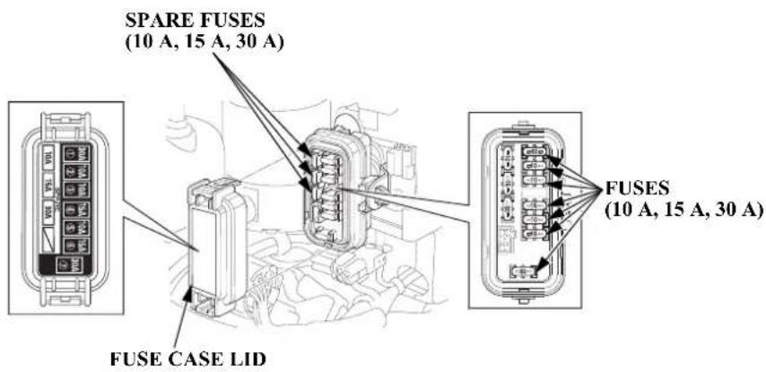
| Fuse No. | Rating Connected Components | |
| 1 30 | A Gathered | fuse (No. 2, 4, 5, 6 Fuses) |
| 2 10 | A Fuel pump | (high pressure side) |
| 3 | 10 A | Power trim/tilt relay, Main relay, Warning buzzer, Indicator, Starter solenoid switch, each meters |
| 4 15 | A Ignition coils | |
| 5 10 | A Data link | connector, HO2 sensor, Trim angle sensor |
| 6 15 | A PGM-FI | ECM, Fuel injectors, CKP sensor 1, 2 |
| 7 30 | A Alternator | (regulator rectifier-battery charging) |
TAKING CARE OF UNEXPECTED PROBLEMS
Fuse Replacement
NOTICE
Disconnect the battery cable at the battery negative (−) terminal before replacing the fuse.
Failure to do so may cause a short circuit.
Main Fuse
- Stop the engine and disconnect the battery cable.
- Remove the engine cover.
- Remove the fuse case lid.
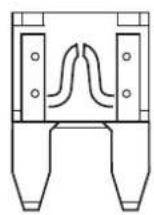
BLOWN FUSE
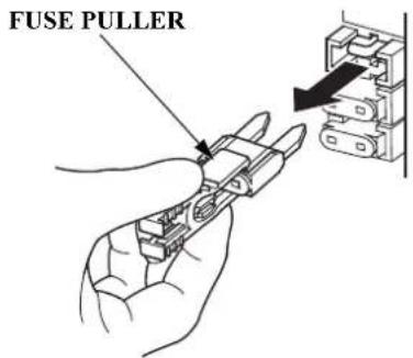
- Use the fuse puller to remove the fuses. If a fuse is blown, install a replacement fuse of the same specified rating. The outboard motor is supplied with spare fuses in the fuse holder.
MAIN FUSE RATINGS: 10 A, 15 A, 30 A
-
Reinstall the fuse case lid, and the engine cover.
-
Reconnect the battery.
NOTICE
Never use a fuse with a rating greater than specified. Serious damage to the electrical system could result.
If a blown fuse is found, try to determine and correct the electrical problem that caused the blown fuse. An uncorrected electrical problem may cause the fuse to blow again.
If fuses continue to blow, take the outboard motor to an authorized Honda Marine dealer for inspection and service, or refer to the shop manual.
TAKING CARE OF UNEXPECTED PROBLEMS
OIL PRESSURE INDICATOR GOES OFF AND ENGINE SPEED IS LIMITED
LH and LHT Types (tiller handle)
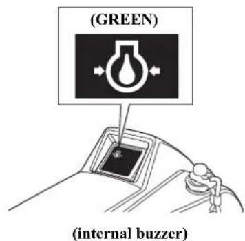
LRT and XRT Types (remote control)
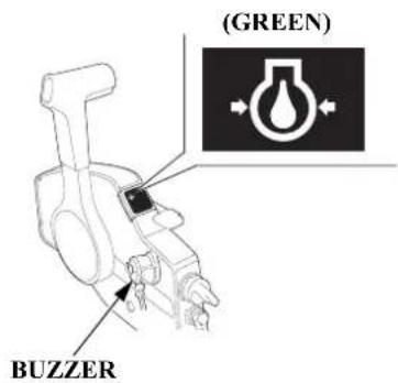
TAKING CARE OF UNEXPECTED PROBLEMS
If the throttle is closed suddenly after full throttle operation, engine speed may drop below the specified idle rpm, and that could activate the engine protection system momentarily.
If low oil pressure activates the engine protection system, stop the engine, check the engine oil level (p. 74), and add oil if needed.
With the engine oil at the recommended level, restart the engine. If the lubrication system is OK, the oil pressure indicator should come on within 30 seconds, and the engine will respond normally to throttle control lever operation.
If the engine protection system remains activated after 30 seconds, return to the nearest boat landing, and have the outboard motor inspected by an authorized Honda Marine dealer.
OVERHEAT INDICATOR COMES ON AND ENGINE SPEED IS LIMITED
LH and LHT Types (tiller handle)
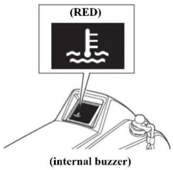
LRT and XRT Types (remote control)
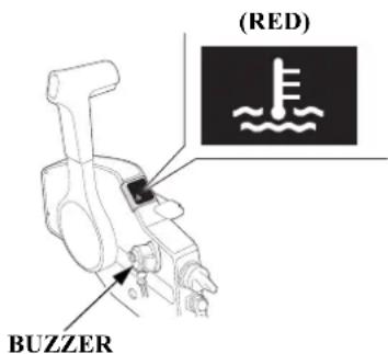
TAKING CARE OF UNEXPECTED PROBLEMS
If the engine is stopped after running at full throttle, and then restarted soon afterward, that could activate the engine protection system momentarily.
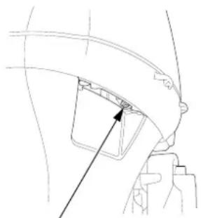
natural_image
Technical line drawing of a mechanical component with a highlighted section (no text or symbols)COOLING SYSTEM INDICATOR
If overheating activates the engine protection system, idle the engine in neutral, and check the cooling system indicator.
If water is flowing from the cooling system indicator, continue idling for 30 seconds. If the cooling system is OK, the overheat indicator should go off within 30 seconds, and the engine will respond normally to throttle control lever operation.
If there is no water flowing from the cooling system indicator, stop the engine, and tilt the outboard motor to inspect the water intake screens. If restricted, clean the water intake screens, return the outboard motor to the running position, restart the engine, and check the cooling system indicator again.
If there is still no water flowing from the cooling system indicator, or if the engine protection system remains activated after 30 seconds, return to the nearest boat landing, and have the outboard motor inspected by an authorized Honda Marine dealer.
TAKING CARE OF UNEXPECTED PROBLEMS
SUBMERGED OUTBOARD MOTOR
A submerged outboard motor must be serviced immediately after it is recovered from the water in order to minimize corrosion.
If there is a Honda Marine dealership nearby, take the outboard motor to the dealer immediately. If you are far from a dealer, proceed as follows:
- Remove the engine cover, and rinse the outboard motor with fresh water to remove salt water, sand, mud, etc.
-
Drain the vapor separator as described on p. 95.
-
Change the engine oil as described on p. 76 – 78. If there was water in the engine crankcase, or if the used engine oil showed signs of water contamination, then a second engine oil change should be performed after running the engine for half an hour.
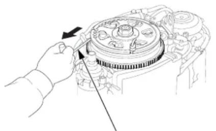
natural_image
Line drawing of a hand operating a mechanical component with a tool, no text or symbols presentEMERGENCY STARTER ROPE
-
Remove the alternator cover (p. 51).
-
Remove the spark plugs (p. 78), and remove the emergency stop switch clip from the emergency stop switch. Pull the emergency starter rope, rotate the flywheel a few revolutions to completely expel any water from the engine's cylinders.
If the engine was running when it submerged, there may be mechanical damage, such as bent connecting rods. If the engine binds when cranked, do not attempt to run the engine until it has been repaired.
NOTICE
When cranking the engine with an open ignition circuit (spark plugs removed from the ignition circuit), remove the clip from the emergency stop switch to prevent possible damage to the ignition system.
TAKING CARE OF UNEXPECTED PROBLEMS
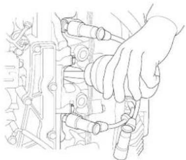
natural_image
Line drawing of a hand adjusting internal components of an engine (no text or symbols)- Pour 1 - 2 teaspoons (5 - 10 cm ^3 ) of engine oil into each spark plug hole, and then pull the emergency starter rope several times to lubricate the inside of the cylinders.
-
Reinstall the spark plugs and alternator cover, and put the emergency stop switch clip into the emergency stop switch.
-
Attempt to start the engine. Be sure the water level is at least 2 inches (5 cm) above the antiventilation plate.
NOTICE
Running the outboard motor without sufficient cooling water will damage the water pump and overheat the engine.
If the engine fails to start, remove the spark plugs and dry them, then reinstall the spark plugs and attempt to start the engine again.
If the engine starts, and no mechanical damage is evident, continue to run the engine for a half hour or longer. Be sure the water level is at least 2 inches (5 cm) above the antiventilation plate to avoid overheating and water pump damage.
- As soon as possible, take the outboard motor to an authorized Honda Marine dealer for inspection and service.
TECHNICAL INFORMATION
Serial Number Locations
Record the product identification number, the engine serial number, and the date of purchase in the space provided on this page. You will need these numbers when ordering parts, and when making technical or warranty inquiries (p. 121).
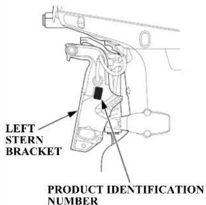
The product identification number is stamped on a plate attached on the left side of the stern bracket.
Product identification number:
Date of purchase:
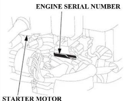
The engine serial number is stamped on the cylinder block under the starter motor which is located in the front of the engine.
Engine serial number:
Battery
For complete information, refer to the battery manufacturer's instructions.
Minimum Requirements
12V - 52Ah/5HR (65Ah/20HR) (CCA420A)
NOTICE
- Be careful to avoid connecting the battery in reverse polarity, as this will damage the battery-charging system in the outboard motor.
- Do not disconnect the battery cables while the engine is running. Disconnecting the cables while the engine is running will damage the outboard motor's electrical system.
- Battery cable extension: Extending the original battery cable will cause the battery voltage to drop due to the increased length of the cable and number of connections. This voltage drop may cause the buzzer to sound momentarily when engaging the starter motor and may prevent the engine from starting. If the engine starts and the buzzer sounds momentarily, there may be barely sufficient voltage reaching the engine.
WARNING: Battery posts, terminals, and related accessories contain lead and lead compounds. Wash your hands after handling.
Emission Control System Information
Source of Emissions
The combustion process produces carbon monoxide, oxides of nitrogen, and hydrocarbons. Control of hydrocarbons and oxides of nitrogen is very important because, under certain conditions, they react to form photochemical smog when subjected to sunlight. Carbon monoxide does not react in the same way, but it is toxic.
Honda utilizes appropriate air/fuel ratios and other emissions control systems to reduce the emissions of carbon monoxide, oxides of nitrogen, and hydrocarbons.
Ignition Timing Control System
The system constantly adjusts the ignition timing, reducing the amount of HC, CO, and NOx produced.
TECHNICAL INFORMATION
PGM-FI System
The PGM-FI system uses sequential multiport fuel injection. It has two subsystems: Engine Control, and Fuel Control. The Engine Control Module (ECM) uses various sensors to determine how much air is going into the engine. It then controls how much fuel to inject under all operating conditions.
The U.S., California Clean Air Acts, and Environment Canada
EPA, California, and Canadian regulations require all manufacturers to furnish written instructions describing the operation and maintenance of emission control systems.
The following instructions and procedures must be followed in order to keep the emissions from your Honda engine within the emission standards.
Tampering and Altering
NOTICE
Tampering is a violation of Federal and California law.
Tampering with or altering the emission control system may increase emissions beyond the legal limit. Among those acts that constitute tampering are:
- Removal or alteration of any part of the intake, fuel, or exhaust systems.
- Alterations that would cause the engine to operate outside its design parameters.
Problems That May Affect Emissions
If you are aware of any of the following symptoms, have your engine inspected and repaired by your servicing dealer.
- Hard starting or stalling after starting.
- Rough idle.
- Misfiring or backfiring under load.
• Afterburning (backfiring). - Black exhaust smoke or high fuel consumption.
Replacement Parts
The emission control systems on your Honda engine were designed, built, and certified to conform with EPA and California emission regulations. We recommend the use of Honda Genuine parts whenever you have maintenance done. These original-design replacement parts are manufactured to the same standards as the original parts, so you can be confident of their performance. The use of replacement parts that are not of the original design and quality may impair the effectiveness of your emission control system.
A manufacturer of an aftermarket part assumes the responsibility that the part will not adversely affect emission performance. The manufacturer or rebuilder of the part must certify that use of the part will not result in a failure of the engine to comply with emission regulations.
Maintenance
Follow the maintenance schedule on p. 70. Remember that this schedule is based on the assumption that your machine will be used for its designed purpose. Sustained high-load operation, or use in unusual conditions, will require more frequent service.
TECHNICAL INFORMATION
Star Label US, Puerto Rico, and US Virgin Islands
A Star label was applied to this outboard motor in accordance with the requirements of the California Air Resources Board.
The Star Label means Cleaner Marine Engine
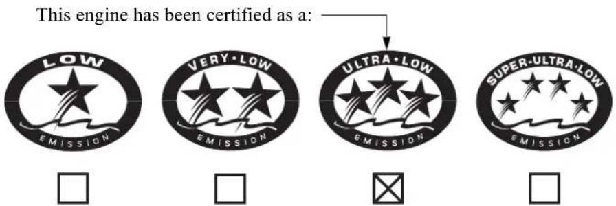
The Symbol for Cleaner Marine Engines:
Cleaner Air and Water - for healthier lifestyle and environment.
Better Fuel Economy - burns up to 30 - 40 percent less gas and oil than conventional carbureted two-stroke engines, saving money and resources.
Longer Emission Warranty - protects consumer for worry-free operation.
TECHNICAL INFORMATION

One Star Low Emission
The one-star label identifies engines that meet the Air Resources Board's Personal Watercraft and Outboard marine engine 2001 exhaust emission standards. Engines meeting these standards have 75% lower emissions than conventional carbureted two-stroke engines. These engines are equivalent to the U.S. EPA's 2006 standards for marine engines.

Two Stars Very Low Emission
The two-star label identifies engines that meet the Air Resources Board's Personal Watercraft and Outboard marine engine 2004 exhaust emission standards. Engines meeting these standards have 20% lower emissions than One Star-Low Emission engines.

Three Stars Ultra Low Emission
The three-star label identifies engines that meet the Air Resources Board's Personal Watercraft and Outboard marine engine 2008 exhaust emission standards or the Sterndrive and Inboard marine engine 2003-2008 exhaust emission standards. Engines meeting these standards have 65% lower emissions than One Star-Low Emission engines.

Four Stars Super Ultra Low Emission
The four-star label identifies engines that meet the Air Resources Board's Sterndrive and Inboard marine engine 2009 exhaust emission standards. Personal Watercraft and Outboard marine engines may also comply with these standards. Engines meeting these standards have 90% lower emissions than One Star-Low Emission engines.
Cleaner Watercraft - Get the Facts 1-800-END-SMOG www.arb.ca.gov
TECHNICAL INFORMATION
Specifications
| MODEL BF40D | ||
| Description code | BBDJ | |
| TypeLH LRT | ||
| Overall length 31 | .3 in (794 mm) 27.3 in (694 mm) | |
| Overall width 14 | 6 in (372 mm) | |
| Overall height 53 | .7 in (1,364 mm) | |
| Transom height (when transom angle is 12°) | 20.5 in (521 mm) | |
| Dry mass [weight]* | 220 lbs (100 kg) 216 lbs (98 kg) | |
| Rated power 29.8 kW (40 HP) | ||
| Full throttle range | 5,000 – 6,000 rpm | |
| Engine type 4 stroke OHC in-line 3 cylinder | ||
| Displacement | 49.3 cu-in (808 cm3) | |
| Spark plug gap 0 | 024 – 0.028 in (0.6 – 0.7 mm) | |
| Steering control system | Tiller handle | Outboard motor-mounted, remote control |
| Starter system Electric starter | ||
| Ignition system Full transistor battery | ||
| Lubrication system | Trochoid pump pressure lubrication | |
| Specified oil | Engine: API standard (SG, SH, SJ)SAE/FC-W 5W-30Gear case: API standard (GL-4) SAE 90Hypoid gear oil |
| Oil capacity | Engine: 2.1 US qt (2.0 L)without oil filter change2.2 US qt (2.1 L)with oil filter changeGear case: 0.43 US qt (0.41 L) |
| CARB star label | ULTRA · LOW EMISSION |
| D.C. output | 12V – 17A |
| Cooling system | Water cooling with thermostat |
| Exhaust system Water exhaust | |
| Spark plugs | DR7EB (NGK), X22 ESR-UB (DENSO) |
| Fuel pump | Low pressure side: mechanical typeHigh pressure side: electrical type |
| Fuel | Unleaded gasoline(86 pump octane or higher) |
| Gear change | Dog type (Forward-Neutral-Reverse) |
| Steering angle | 35° right and left |
| Trim angle | – 4° to 12° (when Transom angle is 12°) |
| Tilt up angle | 63° (when Transom angle is 12°) |
| Transom angle | 8°, 12°, 16°, 20°, 24° |
* With propeller
Honda outboard motors are power rated in accordance with NMMA procedures and using the ICOMIA standard 28/23.
Specifications
| MODEL BF50D | ||
| Description code | BBEJ | |
| TypeLHT LRT, XRT | ||
| Overall length 31.3 in (794 mm) 27.3 in (694 mm) | ||
| Overall width 14.6 in (372 mm) | ||
| Overall height 53.7 in (1,364 mm) | LRT: 53.7 in (1,364 mm)XRT: 57.7 in (1,465 mm) | |
| Transom height (when transom angle is 12°) | 20.5 in (521 mm) | LRT: 20.5 in (521 mm)XRT: 24.5 in (622 mm) |
| Dry mass [weight]* | 225 lbs (102 kg) LRT: 216 lbs (98 kg)XRT: 225 lbs (102 kg) | |
| Rated power 37.3 kW (50 HP) | ||
| Full throttle range | 5,500 – 6,000 rpm | |
| Engine type 4 stroke OHC in-line 3 cylinder | ||
| Displacement | 49.3 cu-in (808 cm3) | |
| Spark plug gap 0 | 024 – 0.028 in (0.6 – 0.7 mm) | |
| Steering control system | Tiller handle | Outboard motor-mounted, remote control |
| Starter system Electric starter | ||
| Ignition system Full transistor battery | ||
| Lubrication system | Trochoid pump pressure lubrication | |
| Specified oil | Engine: API standard (SG, SH, SJ)SAE/FC-W 5W-30Gear case: API standard (GL-4) SAE 90Hypoid gear oil |
| Oil capacity | Engine: 2.1 US qt (2.0 L)without oil filter change2.2 US qt (2.1 L)with oil filter changeGear case: 0.43 US qt (0.41 L) |
| CARB star label | ULTRA · LOW EMISSION |
| D.C. output | 12V – 17A |
| Cooling system | Water cooling with thermostat |
| Exhaust system W | Water exhaust |
| Spark plugs | DR7EB (NGK), X22 ESR-UB (DENSO) |
| Fuel pump | Low pressure side: mechanical typeHigh pressure side: electrical type |
| Fuel | Unleaded gasoline(86 pump octane or higher) |
| Gear change | Dog type (Forward-Neutral-Reverse) |
| Steering angle | 35° right and left |
| Trim angle | – 4° to 12° (when Transom angle is 12°) |
| Tilt up angle | 63° (when Transom angle is 12°) |
| Transom angle | 8°, 12°, 16°, 20°, 24° |
* With propeller
Honda outboard motors are power rated in accordance with NMMA procedures and using the ICOMIA standard 28/23.
TECHNICAL INFORMATION
BF40D/BF50D Tune-up
| Spark plug gap | 0.024 - 0.028 in (0.6 - 0.7 mm) | See page 79 |
| Idle speed 850 ± 50 rpm See shop manual | ||
| Valve clearance Intake: 0.15 ± 0.02 mm | Exhaust: 0.23 ± 0.02 mm | See shop manual |
| Other specifications No other adjustment is needed | ||
CONSUMER INFORMATION
Honda Publications (United States, Puerto Rico, and U.S. Virgin Islands)
These publications will give you additional information for maintaining and repairing your outboard motor.
Shop Manual
This manual covers complete maintenance and overhaul procedures. It is intended to be used by a skilled technician.
Available through your Honda Marine dealer or visit http://marine.honda.com/owners/manuals/shop-manuals.
Parts Catalog
This manual provides complete, illustrated parts lists. The catalog is available through your Honda Marine dealer.
Accessory Catalog
Your authorized Honda Marine dealer offers a wide selection of accessories (optional equipment, oils, and lubricants) to enhance your boating experience.
Visit http://marine.honda.com and click on PARTS & ACCESSORIES to see the entire catalog of accessories.
Customer Service Information
Contacting Honda
Your Owner's Manual was written to cover most of the questions you might ask about your Honda. Any questions not answered in the Owner's Manual can be answered by your Honda dealer. If your dealer doesn't have an immediate answer, they should be able to get it for you.
If you have a difference of opinion with your dealer, please remember that each dealership is independently owned and operated. That's why it's important to work to resolve any differences at the dealership level. If the service personnel are unable to assist you, please discuss your concerns with the dealer management such as the Service Manager or the dealership's owner.
If you need to contact Honda regarding your experiences with your Honda product or with your dealer, please contact the Honda office in your region:
American Honda Motor Co., Inc.
Marine Division
Customer Relations Office 4900 Marconi Drive
Alpharetta, GA 30005-8847
Telephone (770) 497-6400
M-F 8:30 am-7:00 pm (Eastern Time Zone)
Honda Canada Inc.
Customer Relations Office 180 Honda Boulevard
Markham, Ontario L6C 0H9
Tel: 1-888-946-6329 (Toll free)
Fax: 1-877-939-0909 (Toll free)
CONSUMER INFORMATION
Please include the following information in your communication:
- Your name, address and telephone number (complete with area code)
- Model and complete serial number
- Date of purchase
• Name and location of selling dealer - Name and location of servicing dealer (if different)
• A detailed description of your concerns
Warranty Coverage
Your new Honda is covered by the following warranties:
- Distributor's Limited Warranty
- Emission Control System Warranty
Please read the warranty statements contained in this manual. There are responsibilities, restrictions, and exclusions that apply to these warranties.
To obtain warranty service you must take your Honda outboard motor, together with proof of original retail purchase date, at your expense, to a Honda engine dealer or distributor authorized to sell that product in the United States, Puerto Rico, the U.S. Virgin Islands or Canada.
It is important to realize that your warranty applies to defects in material or workmanship of your Honda. Your warranty coverage does not apply to normal wear or deterioration associated with using your Honda outboard motor.
Your warranty coverage will not be voided if you choose to perform your own maintenance. However, you should have the proper tools and service information and be mechanically qualified. Failures that occur due to modifications, improper maintenance, or service are not covered.
Warranty Service
Please remember that recommended maintenance interval servicing is not included in your warranty coverage. Additionally, your warranty does not apply to the normal wear of items (such as spark plug(s), water pump, etc.).
As the owner of a Honda product, your servicing dealer may ask you to authorize an inspection. If the problem is covered under warranty, your dealer will perform any warranty repairs for you at no cost. However, you may be responsible for additional non-warranty charges.
If you have questions about warranty coverage or the nature of the repair, it is best to talk to the service manager of your Honda dealer.
Sometimes, in spite of the best intentions of all concerned, a misunderstanding may occur. If you
aren't satisfied with your dealer's handling of the situation, we suggest you discuss your problem with the appropriate member of the dealership's management team. If the problem has already been reviewed with the appropriate manager of the Service, Parts, or Sales department, contact the owner of the dealership or their designated representative.
CONSUMER INFORMATION
Warranty Statements
The American Honda Distributor's Limited Warranty applies to outboards purchased in the United States, Puerto Rico, or the U.S. Virgin Islands. The Honda Canada Distributor's Warranty applies to outboards purchased in Canada. The product warranty is only valid in the country where the product was purchased.
United states, Puerto Rico and Virgin Islands
Distributor's Limited Warranty
This warranty is limited to Honda Outboard Motors and related original equipment distributed by American Honda Motor Co., Inc., Power Equipment Division, 4900 Marconi Drive, Alpharetta, Georgia 30005-8847.
| Products Covered by Warranty: Length of Warranty: (from date of original retail purchase) | |||
| NONCOMMERCIAL/ NONRENTAL | COMMERCIAL/RENTAL | STATE/LOCAL/FEDERAL GOVERNMENT | |
| All models purchased before July 1, 2008(1)(2) | 36 months 12 months | 24 months | |
| All Models purchased on or after July 1, 2008(2) | 60 months 12 months | 24 months | |
| Related original equipment items:BF2 through BF30 models: Portable fuel tank and original propeller.All models: Primer bulb/fuel line assembly and tiller handle. | The same duration as the outboard with which they were purchased. | ||
(1) Models purchased prior to July 1, 2008 (unless previously purchased with True-5 warranty from a participating dealer).
(2) 35, 65, & 105 Jet models: Jet pump assembly is a dealer installed option. Jet pump warranty is provided by Specialty Manufacturing Co. (Outboard Jets).
To Qualify for This Warranty:
The Honda Outboard Motor must be purchased from American Honda or a dealer authorized by American Honda to sell Honda Outboard Motors in the United States, Puerto Rico, or the U.S. Virgin Islands. This limited warranty applies to the first retail purchaser and each subsequent owner during the applicable warranty time period.
What American Honda Will Repair or Replace Under Warranty:
American Honda will repair or replace, at its option, any part that is proven to be defective in material or workmanship under normal use during the applicable warranty time period. Warranty repairs and replacements will be made without charge for parts or labor. Anything replaced under warranty becomes the property of American Honda Motor Company, Inc.
All parts replaced under warranty will be considered as part of the original product and any warranty on those parts will expire coincidentally with the original product warranty.
To Obtain Warranty Service:
You must, at your expense, take your Honda Outboard Motor and proof of the original purchase date to any dealer who is authorized to service Honda Outboard Motors in the United States, Puerto Rico, or the U.S. Virgin Islands, during the dealer's normal business hours. If you are unable to obtain warranty service, or are dissatisfied with the warranty service you receive, take the following steps: First, contact the owner of the dealership involved; normally this should resolve the problem. However, if you should require further assistance, write or call the Honda Marine Customer Relations. Please see Contacting Honda page 121.
CONSUMER INFORMATION
Exclusions:
This warranty does not extend to the following:
- Conditions caused by lack of routine maintenance or improper storage (as outlined in the Owner's Manual)
- Conditions caused by the use of propeller (s) that do not allow the outboard motor to run in its recommended full throttle rpm range
- Operation inconsistent with the recommended operation/ duty cycle (as outlined in the Owner's Manual)
- Parts affected or damaged by an abuse, submersion and/or collision
• Normal wear and tear - Fuel contamination and water entering engine through the fuel intake, air intake or exhaust system
- Operation with fuels, oils, additives and lubricants which are not suitable for use in the product
- Use in an application for which the outboard motor was not designed, such as racing or competitive use or any other misuse or neglect
- Incorporation of unsuitable attachments or parts
- The unauthorized alteration, improper installation and/or rigging, or any causes other than defects in material or workmanship
-
Corrosion to steering system or electrical components, corrosion due to electrolysis, water born foreign chemicals, improper service or corrosion caused by damage or abuse
-
Reimbursement for towing charges, in and out of water charges, or technician travel time
- Growth of marine organisms on outboard motor surfaces, external or internal
- Any product that has ever been declared a total loss or sold for salvage by a financial institution or insurer, or that has been issued a “salvage” or similar title under any state’s law.
Disclaimer of consequential damage and limitation of implied warranties:
American Honda disclaims any responsibility for loss of time or use of the outboard, revenue, or the equipment in which the outboard is installed, transportation, commercial loss, or any other incidental or consequential damage. Any implied warranties are limited to the duration of this written limited warranty. Some states do not allow limitations on how long an implied warranty lasts and/or do not allow the exclusion or limitation of incidental or consequential damages, so the above exclusions and limitations may not apply to you. This warranty gives you specific legal rights, and you may also have other rights which vary from state to state.
Accessories and Replacement Parts
This warranty is limited to Honda Marine parts, accessories and apparel when distributed by American Honda Motor Co., Inc., 1919 Torrance Blvd., Torrance, California 90501-2746.
| Products Covered by Warranty: Length of Warranty: (from date of original retail purchase) | |||
| Non Commercial Commercial/Rental Local/State/Federal | Government | ||
| Accessories other than noted below | 12 months 3 months | 3 months | |
| Emission related accessories:Portable fuel tanks, fuel line assemblies, and water/fuel separators | 24 months 24 months | 24 months | |
| Replacement Parts | 6 months 3 months | 3 months | |
To Qualify for This Warranty:
- The accessories or replacement parts must be purchased from American Honda or a dealer, distributor, or distributor's dealer authorized by American Honda to sell those products in the United States, Puerto Rico, and the U.S. Virgin Islands. Parts and Accessories must be purchased for installation on original Honda equipment or engines to be eligible for warranty coverage. Installing parts and accessories on non-Honda products or engines voids this warranty.
- You must be the first retail purchaser. This warranty is not transferable to subsequent owners.
What American Honda Will Repair or Replace Under Warranty:
American Honda will repair or replace, at its option, any
marine product accessories or replacement parts that are proven to be defective in material or workmanship under normal use during the applicable warranty time period. Anything replaced under warranty becomes the property of American Honda Motor Company, Inc. All parts replaced under warranty will be considered as part of the original product and any warranty on those parts will expire coincidentally with the original product warranty.
Accessories and replacement parts, installed by a dealer who is authorized by American Honda to sell them, will be repaired or replaced under warranty without charge for parts or labor. If installed by anyone else, accessories and replacement parts will be repaired or replaced under warranty without charge for parts, but any labor charges will be the responsibility of the purchaser.
CONSUMER INFORMATION
To Obtain Warranty Service:
You must, at your expense, take the Honda Outboard Motor product accessory or replacement part or the outboard motor or boat on which the accessory or replacement part is installed, and proof of purchase to any Honda Marine authorized service facility or dealer in the United States, Puerto Rico, or the U.S. Virgin Islands, during normal business hours.
Exclusions:
This warranty does not extend to accessories or parts affected or damaged by collision, normal wear, use in an application for which the product was not designed or any other misuse, neglect, incorporation or use of unsuitable attachments or parts, unauthorized alteration, improper installation, or any causes other than defects in material or workmanship of the product.
Installing parts and accessories on non-Honda products or engines voids this warranty.
Disclaimer of consequential damage and limitation of implied warranties:
American Honda disclaims any responsibility for loss of time or use of the outboard motor, or the boat on which the product is installed, transportation, commercial loss, or any other incidental or consequential damage. Any implied warranties are limited to the duration of this
written warranty. Some states do not allow limitations on how long an implied warranty lasts and/or do not allow the exclusion or limitation of incidental or consequential damages, so the above exclusions and limitations may not apply to you. This warranty gives you specific legal rights, and you may also have other rights which vary from state to state.
Emission Control System Warranty
Your new Honda outboard engine complies with both the U.S. EPA and State of California emission regulations. American Honda provides the same emission warranty coverage for outboard engines sold in all 50 states. In all areas of the United States your outboard engine must be designed, built, and equipped to meet the U.S. EPA and California Air Resources Board emission standard for spark ignited marine engines.
CALIFORNIA EMISSION CONTROL WARRANTY STATEMENT YOUR WARRANTY RIGHTS AND OBLIGATIONS
The California Air Resources Board (CARB) and American Honda Motor Co., Inc. are pleased to explain the emission control system warranty on your 2013-2014 Honda outboard engine. In California, new outboard engines must be designed, built, and equipped to meet the state's stringent anti-smog standards. American Honda Motor Co., Inc. must warrant the emission control system on your outboard engine for the periods of time listed below provided there has been no
abuse, neglect, or improper maintenance of your outboard engine.
Your emission control system may include parts such as the carburetor or fuel injection system, the ignition system, and catalytic converter. Also included may be hoses, belts, connectors, and other emission-related assemblies.
Where a warrantable condition exists, American Honda Motor Co., Inc. will repair your outboard engine at no cost to you including diagnosis, parts, and labor.
MANUFACTURER'S WARRANTY COVERAGE:
Select emission control parts from model year 2010 and later outboard engines are warranted for five years or 250 hours of use, whichever first occurs; or the length of the Honda Marine Distributor's Limited Warranty, whichever is longer. However, warranty coverage based on the hourly period is only permitted for engines equipped with hour meters as defined in § 2441 (a)(13)* or their equivalent. If any emission-related part on your engine is defective under warranty, the part will be repaired or replaced by American Honda Motor Co., Inc.
* California Code of Regulations.
CONSUMER INFORMATION
OWNER'S WARRANTY RESPONSIBILITIES:
As the outboard engine owner, you are responsible for the performance of the required maintenance listed in your owner's manual. American Honda Motor Co., Inc. recommends that you retain all receipts covering maintenance on your outboard engine, but American Honda Motor Co., Inc. cannot deny warranty solely for the lack of receipts or your failure to ensure the performance of all scheduled maintenance.
As the outboard engine owner, you should, however, be aware that American Honda Motor Co., Inc. may deny you warranty coverage if your outboard engine or a part has failed due to abuse, neglect, improper maintenance, or unapproved modifications.
You are responsible for presenting your outboard engine to a Honda Marine dealer as soon as a problem exists. The warranty repairs will be completed in a reasonable amount of time, not to exceed 30 days.
If you have any questions regarding your warranty rights and responsibilities, you should contact American Honda Motor Co., Inc., Marine Division Customer Relations Office. Please see Contacting Honda page 121.
WARRANTY COVERAGE:
Honda outboard engines certified to the CARB and EPA 2010 and later regulation are covered by this warranty to be free from defects for a minimum of five years or 250 hours of operation, whichever comes first; or the length of the Honda Marine Distributor's Limited Warranty, whichever is longer, from the date of delivery to the retail purchaser. This warranty is transferred to each subsequent purchaser for the duration of the warranty period. Warranty repairs will be made without charge for diagnosis, parts, and labor. All defective parts replaced under this warranty become the property of American Honda Motor Co., Inc. A list of warranty parts is on page 132. Normal maintenance items, such as spark plugs and filters, that are on the warranted parts list are warranted up to their required replacement interval only. American Honda Motor Co., Inc. is also liable for damages to other engine components caused by a failure of any warranted part during the warranty period. Only Honda approved replacement parts will be used in the performance of any warranty repairs, and they will be provided without charge to the owner. You may use any replacement part as defined in § 1900 (b)(20)* in the performance of any maintenance or repairs. If a replacement part is used in the repair or maintenance of your engine, and an authorized Honda Marine dealer determines it causes the failure of a warranted part, your warranty claim may be denied. If the part in question is not related to the reason that your engine requires repair, your claim will not be denied.
* California Code of Regulations.
TO OBTAIN WARRANTY SERVICE:
You must take your Honda outboard engine, along with your sales registration card or other proof of original purchase date, at your expense, to any Honda Marine dealer that is authorized by American Honda Motor Co., Inc. to sell and service that Honda marine product during its normal business hours. Claims for repair or adjustment found to be caused solely by defects in material or workmanship will not be denied because the engine was not properly maintained and used. If you are unable to obtain warranty service, or are dissatisfied with the warranty service you received, contact the owner of the dealership involved. Normally this should resolve your problem. However, if you require further assistance, write or call the Honda Marine Customer Relations Office of American Honda Motor Co., Inc.
EXCLUSIONS:
Failures other than those resulting from defects in material or workmanship are not covered by this warranty. This warranty does not extend to emission control systems or parts which are affected or damaged by owner abuse, neglect, improper maintenance, misuse, misfueling, improper storage, and/or collision, the incorporation of, or use of, unsuitable attachments, or the unauthorized alteration of any part.
This warranty does not cover replacement of expendable maintenance items made in connection with required maintenance service after the items first scheduled replacement as listed in the maintenance section of the product owner's manual, such as: spark plugs and filters.
DISCLAIMER OF CONSEQUENTIAL DAMAGE AND LIMITATION OF IMPLIED WARRANTIES:
American Honda Motor Co., Inc. disclaims any responsibility for incidental or consequential damages such as loss of time or the use of outboard engine, or any commercial loss due to the failure of the equipment; and any implied warranties are limited to the duration of this written warranty. This warranty is applicable only where the California or U.S. EPA emission control system warranty regulation is in effect.
CONSUMER INFORMATION
EMISSION CONTROL SYSTEM WARRANTY PARTS:
| SYSTEMS COVERED BY THIS WARRANTY: | PARTS DESCRIPTION: |
| Fuel Metering | Carburetor assembly, Throttle body, Fuel injector, Fuel pump, Fuel pressure regulator, Throttle position sensor, Intake air temperature sensor, Engine temperature sensor, Manifold absolute pressure sensor, Idle air control valve, Barometric pressure sensor, Fuel line solenoid valve, Intake manifold, Intake valves, and Oxygen sensor or Air fuel ratio sensor |
| Evaporative | Portable fuel tank, Fuel cap, Fuel hoses, Primer bulb, Fuel hose joint |
| Air Induction | Air intake duct, Vapor separator, Intake manifold tuning valve (Intake air bypass control valve) |
| Ignition | Flywheel magneto, Ignition pulse generator, Ignition coil assembly, Ignition control module, Engine control module, Crankshaft position sensor, Spark plug cap, Spark plug*, Knock sensor, and Camshaft position sensor |
| Lubrication System Oil pump and internal parts | |
| Crankcase Emission Control | Crankcase breather tube, Positive crankcase ventilation valve, Oil filler cap |
| Exhaust Exhaust manifold and Exhaust valves | |
| Valve Control System Rocker arm oil control valve | |
| Miscellaneous Parts | Tubing, fittings, scals, gaskets, and clamps associated with these listed systems. |
| * Covered up to the first required replacement only. See the Maintenance Schedule on pages 70 and 71. | |
Canada
Distributor's Warranty
HONDA CANADA INC., for and on behalf of Honda Motor Co. Ltd., Tokyo, Japan, gives the following written warranty on each new marine product manufactured by Honda Motor Co. Ltd., Japan, distributed in Canada by Honda Canada Inc. and sold by authorized Honda Marine dealers.
Whenever used herein, the word “Honda” refers to Honda Canada Inc. and/or Honda Motor Co. Ltd., as appropriate from the context.
HONDA WARRANTS THAT each new Honda marine product will be free, under normal use and maintenance, from any defects in material or workmanship for the relevant warranty period set forth below. If any defects should be found in a Honda marine product within the relevant warranty period, necessary repairs and replacements with a new part or the Honda equivalent shall be made at no cost to the consumer for parts and labour, when Honda acknowledges that such defects are attributable to faulty material or workmanship at the time of manufacture.
WARRANTY PERIOD RETAILED ON OR AFTER APRIL 1, 2005:
| Non-commercial use | Commercial use | |
| All Honda Outboard Models | 36 Months 12 Months | |
THIS WARRANTY COVERS
a) Any Honda marine product purchased in Canada from an authorized Honda dealer which has been registered at the time of purchase on a form provided by Honda, which has had set-up and pre-delivery service performed by an authorized Honda dealer and which is normally operated in Canada;
b) Any factory installed part (except normal maintenance parts referred to in “THIS WARRANTY DOES NOT COVER”); and
c) Any marine product on which required maintenance services have been performed as prescribed in the Owner's Manual.
CONSUMER INFORMATION
THIS WARRANTY DOES NOT COVER
a) Any repairs required as a result of collision, accident, striking any object, misuse or lack of required maintenance;
b) Any repairs required as a result of any attachments, parts or devices installed by or repairs done by a party other than an authorized Honda dealer;
c) Any outboard that has been operated out of water, (Run Dry) damaging the water pump and or engine components due to insufficient cooling water.
d) Any marine products modified, altered, disassembled or remodelled;
c) Normal maintenance services, including tightening of nuts, bolts and fittings and engine tune-up and the replacement of parts made in connection with normal maintenance services including filters, spark plugs and wires, fuses, belts, lubricants and other expendables susceptible to natural wear;
f) Outboard propeller or shear pin.
g) All accessories or attachments.
THE OWNER'S OBLIGATION
In order to maintain the validity of this DISTRIBUTORS WARRANTY, the required maintenance services as set forth in the Owner's Manual must be performed at the proper intervals and detailed receipts and records retained as proof.
TO OBTAIN WARRANTY SERVICE
You must take your Honda marine product, at your expense, during normal service hours, to any authorized Honda Marine dealership. If you are unable to obtain or are dissatisfied with the warranty service you receive, first contact the owner of the dealership involved; this should resolve the problem. If you require further assistance, contact Honda Canada's Customer Relations Department at:
HONDA CANADA INC.
Customer Relations Office
180 Honda Boulevard
Markham, Ontario L6C 0H9
TELEPHONE: 1-888-946-6329 TOLL FREE
FAX : 1-877-939-0909 TOLL FREE
REPLACEMENT PARTS AND ACCESSORY WARRANTY
New genuine Honda replacement parts or accessories sold to a consumer or installed by an authorized Honda Marine dealer which are not covered by the DISTRIBUTORS WARRANTY are warranted for a period of one year from date of purchase, provided, however, that this Replacement Parts and Accessory Warranty does not apply to any replacement parts modified, used with, or installed on a marine product for which the replacement parts were not intended. Electrical components that are not installed by the dealer (sold over the counter) are not covered by warranty.
ENTIRE WRITTEN WARRANTY
This DISTRIBUTORS WARRANTY and the REPLACEMENT PARTS AND ACCESSORY WARRANTY are the only and the entire written warranties given by Honda for Marine engines. No dealer or his agent or employee is authorized to extend or enlarge on these warranties on behalf of Honda by any written or verbal statement or advertisement.
DISCLAIMER
To the extent the law permits, Honda disclaims any responsibility for loss of time or use of the product, transportation or towing costs or any other indirect, incidental or consequential damage, inconvenience or commercial loss.
NOTICE TO CONSUMER
The provisions contained in these written warranties are not intended to limit, modify, take away from, disclaim or exclude any warranties set forth in or the operation of The Consumer Products Warranties Act, 1977 (Saskatchewan), The Consumer Product Warranty and Liability Act (New Brunswick), The Consumer Protection Act (Quebec), or any other similar provincial or federal legislation.
INDEX
Alternator (ACG) Indicator 32
Anodes 37
Replacement 88
ARE YOU READY TO GET UNDERWAY? 38
Battery 113
Will Not Charge 105
BEFORE OPERATION 38
BREAK-IN PROCEDURE 41
CLEANING AND FLUSHING 91
Common Controls 30
COMPONENT AND CONTROL LOCATIONS ..... 14
CONSUMER INFORMATION 121
CONTROL AND FEATURE IDENTIFICATION CODES......13
CONTROLS 20
CONTROLS AND FEATURES 13
Cooling System Indicator 34
CRUISING 60
Customer Service Information 121
Distributor's Limited Warranty 124
Distributor's Warranty 133
Electric Starter Will Not Operate 105
EMERGENCY
STARTER ROPE 69
STARTING 51
Emergency Stop Switch Clip and Emergency Stop Switch
LH and LHT Types 20
Side-Mount Control Type 25
Emission Control System Information 113
Emission Control System Warranty 129
Engine
Cover
Latches (front/rear) 30
REMOVAL AND INSTALLATION 73
Oil
Change 76
Level Check 74
Recommendations 78
OVERHEATS 104
WILL NOT START 100
INDEX
Fast Idle Lever 27
Fuel
Filler Cap Vent Knob [standard equipment (Canadian types)], [optional equipment (American types)] .... 36
Filter/Water Separator Inspection and Service ..... 84
Gauge [standard equipment (Canadian types)], [optional equipment (American types)] .... 31
HOSE CONNECTIONS 43
PRIMING 44
Priming Bulb 36
RECOMMENDATIONS 83
Fuse Replacement 106
FUSES 105
Gearshift Lever (LH and LHT Types) 22
Gearshift/Throttle Control Lever (LRT and XRT Types) 26
GEARSHIFT AND THROTTLE OPERATION ..... 57
HARD STARTING OR STALLS AFTER STARTING ....103
HOISTING THE OUTBOARD MOTOR 97
Honda Publications 121
Ignition Switch LH and LHT Types .... 20 LRT and XRT Types .... 24
IMPORTANT SAFETY INFORMATION 7
INDICATORS 32
INFREQUENT OR OCCASIONAL USE 45
INSTRUMENTS 31
IS YOUR OUTBOARD MOTOR READY TO GO? 38
Lubrication Points 80
MAINTENANCE SAFETY 68
MAINTENANCE SCHEDULE 70
MANUAL RELIEF VALVE 29,73
Malfunction Indicator 32
MOORING, BEACHING, LAUNCHING 65
MULTIPLE OUTBOARD MOTORS 66
NMEA INTERFACE COUPLER 36
INDEX
Oil Pressure Indicator 33
OIL PRESSURE INDICATOR GOES OFF AND ENGINE SPEED IS LIMITED 107
OPERATION 41
OTHER FEATURES 35
OUTBOARD MOTOR SAFETY 7
Overheat Indicator 34
OVERHEAT INDICATOR COMES ON AND ENGINE SPEED IS LIMITED 108
Overrev Limiter 35
PORTABLE FUEL TANK
[standard equipment (Canadian types)], [optional equipment (American types)] ..... 35, 43 and Tank Filter Cleaning ..... 87
Power Tilt Switch (engine pan) 28
Power Trim/Tilt Switch 28
Propeller Replacement 89
REFUELING 81
REMOVAL FROM STORAGE 98
SAFE OPERATING PRECAUTIONS 41
SAFETY LABEL LOCATIONS....9
Serial Number Locations 112
SERVICING YOUR OUTBOARD MOTOR 67
Spark Plug Service 78
Specifications 118
Star Label 116
STARTING THE ENGINE 45
LH and LHT Types 45
LRT and XRT Types Side-Mount Control Type 48
Steering Friction Adjuster (LH and LHT Types) ...... 22
STEERING 59
STOPPING THE ENGINE 54
Emergency Engine Stopping 54
Normal Engine Stopping 55
STORAGE 94
Engine oil 97
Fuel 94
STORAGE PRECAUTIONS 97
SUBMERGED OUTBOARD MOTOR 110
INDEX
Tachometer [standard equipment (Canadian types)], [optional equipment (LRTA and XRTA types)] ..... 31
TAKING CARE OF UNEXPECTED PROBLEMS .. 100
TECHNICAL INFORMATION 112
THE IMPORTANCE OF MAINTENANCE ...... 67
Throttle Friction Adjuster (LH and LHT Types) .... 22 Grip (LH and LHT Types) .... 21
Tiller Handle Height/Angle Adjustment (LH and LHT Types) 40
Tilt Lock Lever 30
TOOL KIT and OWNER'S MANUAL 69
TRANSPORTING 99
WITH OUTBOARD MOTOR INSTALLED ON BOAT 99
WITH OUTBOARD MOTOR REMOVED FROM BOAT 99
Trim Meter [standard equipment (Canadian types)], [optional equipment (LRTA and XRTA types)] ..... 31
Trim Tab 30
TRIM TAB ADJUSTMENT 72
TRL (Trolling) Control Switch [optional equipment (except LHA and LHTC types)] 29
Trolling Speed Control [optional equipment (except LHA and LHTC types)] 62
Warranty Statements 124
MEMO
HONDA
The Power of Dreams
natural_image
Grid pattern of blue squares with white borders, no text or symbols present□□==□□□□
□□;□□□==□□□□□□
EM3

英 N HCAH
3 ULQNHG□LQ□&KLQD
US:K2
C:K3
- BF40D·BF50D Owner's Manual
- WARNING:
- INTRODUCTION
- A FEW WORDS ABOUT SAFETY
- CONTENTS
- OUTBOARD MOTOR SAFETY
- IMPORTANT SAFETY INFORMATION
- Operator Responsibility
- Refuel With Care
- Carbon Monoxide Hazard
- Canadian Types
- CONTROLS AND FEATURES
- CONTROLS
- LH and LHT Types (tiller handle)
- Emergency Stop Switch Clip and Emergency Stop Switch
- Fast Idle Lever
- LHT, LRT and XRT Types (power trim/tilt)
- Power Trim/Tilt Switch
- LRT and XRT Types
- Manual Relief Valve
- Except LHA and LHTC types TRL (Trolling) Control Switch [optional equipment]
- Common Controls
- Engine Cover Latches
- Trim Tab
- INSTRUMENTS
- Trim Meter
- Tachometer
- Fuel Gauge
- INDICATORS
- Alternator (ACG) Indicator
- Malfunction Indicator
- Oil Pressure Indicator
- Overheat Indicator
- OTHER FEATURES
- Overrev Limiter
- NMEA Interface Coupler
- Anodes
- BEFORE OPERATION
- ARE YOU READY TO GET UNDERWAY?
- Knowledge
- Safety
- WARNING
- Safety Inspection
- Maintenance Inspection
- Tiller Handle Height/Angle Adjustment (LH and LHT types)
- OPERATION
- SAFE OPERATING PRECAUTIONS
- BREAK-IN PROCEDURE
- Break-in period: 10 hours
- First 15 minutes:
- Next 45 minutes:
- Next 60 minutes:
- Next 8 hours:
- NOTICE
- FUEL HOSE CONNECTIONS
- FUEL PRIMING
- INFREQUENT OR OCCASIONAL USE
- STARTING THE ENGINE
- EMERGENCY STARTING
- NOTE:
- STOPPING THE ENGINE
- Emergency Engine Stopping
- LRT and XRT Types (remote control)
- Normal Engine Stopping
- GEARSHIFT AND THROTTLE OPERATION
- STEERING
- Steering Friction Adjuster
- CRUISING
- Engine Speed
- Trim
- LH Type
- LHT, LRT and XRT Types
- LHT Type
- Trolling Speed Control [optional equipment (except LHA and LHTC types)]
- MOORING, BEACHING, LAUNCHING
- MULTIPLE OUTBOARD MOTORS
- SERVICING YOUR OUTBOARD MOTOR
- THE IMPORTANCE OF MAINTENANCE
- MAINTENANCE SAFETY
- Safety Precautions
- SPARE SWITCH CLIP (LH and LHT Types) AND EMERGENCY STARTER ROPE
- EMERGENCY STARTER ROPE
- TOOL KIT and OWNER'S MANUAL
- MAINTENANCE SCHEDULE
- TRIM TAB ADJUSTMENT
- ENGINE COVER REMOVAL AND INSTALLATION
- Engine Oil Level Check
- Engine Oil Change
- Engine Oil Recommendations
- Spark Plug Service
- Lubrication Points
- REFUELING
- FUEL RECOMMENDATIONS
- Use unleaded gasoline with a pump octane rating of 86 or higher.
- Fuel Filter/Water Separator Inspection and Service
- Fuel Tank
- Propeller Replacement [standard equipment (Canadian types)] [optional equipment (American types)]
- Removal
- Installation
- CLEANING AND FLUSHING
- Cleaning
- Flushing With a Garden Hose Garden Hose Adapter (optional equipment)
- STORAGE
- Fuel
- Adding a Fuel Stabilizer
- Draining the Fuel System
- Engine Oil
- HOISTING THE OUTBOARD MOTOR
- STORAGE PRECAUTIONS
- REMOVAL FROM STORAGE
- TRANSPORTING
- WITH OUTBOARD MOTOR INSTALLED ON BOAT
- All Types
- WITH OUTBOARD MOTOR REMOVED FROM BOAT
- TAKING CARE OF UNEXPECTED PROBLEMS
- FUSES
- Electric Starter Will Not Operate
- Battery Will Not Charge
- Fuse Replacement
- Main Fuse
- OIL PRESSURE INDICATOR GOES OFF AND ENGINE SPEED IS LIMITED
- OVERHEAT INDICATOR COMES ON AND ENGINE SPEED IS LIMITED
- SUBMERGED OUTBOARD MOTOR
- TECHNICAL INFORMATION
- Serial Number Locations
- Battery
- Minimum Requirements
- Emission Control System Information
- Source of Emissions
- Ignition Timing Control System
- PGM-FI System
- The U.S., California Clean Air Acts, and Environment Canada
- Tampering and Altering
- Problems That May Affect Emissions
- Replacement Parts
- Maintenance
- Star Label US, Puerto Rico, and US Virgin Islands
- The Star Label means Cleaner Marine Engine
- The Symbol for Cleaner Marine Engines:
- CONSUMER INFORMATION
- Honda Publications (United States, Puerto Rico, and U.S. Virgin Islands)
- Shop Manual
- Parts Catalog
- Accessory Catalog
- Customer Service Information
- Contacting Honda
- American Honda Motor Co., Inc.
- Honda Canada Inc.
- Warranty Coverage
- Warranty Service
- Warranty Statements
- United states, Puerto Rico and Virgin Islands
- Distributor's Limited Warranty
- To Qualify for This Warranty:
- What American Honda Will Repair or Replace Under Warranty:
- To Obtain Warranty Service:
- Exclusions:
- Disclaimer of consequential damage and limitation of implied warranties:
- Accessories and Replacement Parts
- Emission Control System Warranty
- CALIFORNIA EMISSION CONTROL WARRANTY STATEMENT YOUR WARRANTY RIGHTS AND OBLIGATIONS
- MANUFACTURER'S WARRANTY COVERAGE:
- OWNER'S WARRANTY RESPONSIBILITIES:
- WARRANTY COVERAGE:
- Canada
- Distributor's Warranty
- THIS WARRANTY COVERS
- THIS WARRANTY DOES NOT COVER
- THE OWNER'S OBLIGATION
- TO OBTAIN WARRANTY SERVICE
- REPLACEMENT PARTS AND ACCESSORY WARRANTY
- ENTIRE WRITTEN WARRANTY
- DISCLAIMER
- NOTICE TO CONSUMER
- INDEX
- HONDA
- The Power of Dreams
Brand : Honda
Model : BF40D (2014)
Category : Outboard motor