
LU 102-180 - Motion detectors THEBEN - Free user manual and instructions
Find the device manual for free LU 102-180 THEBEN in PDF.
| Product type | Motion detector with halogen floodlight |
| Brand | THEBEN |
| Model | LU 102-180 |
| Rated voltage | 230 V ~ 50 Hz |
| Maximum load (halogen lamp) | 500 W (cos φ = 1) |
| Transmission range | Approx. 50 m outdoors |
| Transmission frequency | 433.92 MHz |
| Modulation | ASK |
| Channel setting | 256 combinations |
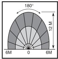
| Max. detection range | 12 m / 180° |
| Adjustable lighting duration | From 5 seconds to 5 minutes |
| Distance setting (METER) | Up to 12 m |
| Brightness threshold (LUX) | From 5 lux to infinity |
| Operating temperature | -20 °C to +45 °C |
| Protection rating | IP 44 |
| Optimal installation height | 2 m to 2.4 m |
| Max. detection angle | 180° |
| Transmitter power supply | 230 V ~ 50 Hz (by fixed wiring) |
| Package contents | Halogen floodlight with detector, manual, U-bracket, 500 W halogen bulb, screws, cable tie, cable grommet, lens protective film |
| Maintenance and cleaning | Clean the lens with a soft dry cloth. Cut the power before any maintenance. |
| Safety | Cut the power before installation. Do not move the internal antenna. Avoid radio interference. |
| General information | Complies with EC directives. Sold in EU and EFTA countries. |
Frequently Asked Questions - LU 102-180 THEBEN
User questions about LU 102-180 THEBEN
0 question about this device. Answer the ones you know or ask your own.
Ask a new question about this device
Download the instructions for your Motion detectors in PDF format for free! Find your manual LU 102-180 - THEBEN and take your electronic device back in hand. On this page are published all the documents necessary for the use of your device. LU 102-180 by THEBEN.
USER MANUAL LU 102-180 THEBEN
natural_image
Black and white photo of a modern streetlight fixture with a hexagonal patterned light source (no text or symbols visible)2
natural_image
Pure mechanical diagram showing a lever mechanism without any text, numbers, or symbolsVue de haut

Vue de côté
natural_image
Diagram of a radar or optical system with a central device and surrounding components (no text or symbols)natural_image
Simple line drawing of a firecracker with smoke and flame (no text or symbols)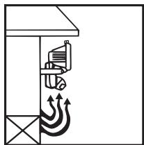
natural_image
Diagram of a building interior with ventilation airflow and mechanical components (no text or labels)Fig. 9
natural_image
Technical line drawing of a mechanical device with a bracket and lever (no text or symbols)natural_image
Line drawing of a megaphone with a handle and spout, labeled Fig. 14 (no text or symbols on the device itself)natural_image
Technical line drawing of a mechanical bracket with two screws and a dashed centerline (no text or symbols)natural_image
Line drawing of a mechanical device with a central bracket and mounting base (no text or symbols)TEST ET REGLAGE


natural_image
Simple diagram of a rectangular shape with labeled dimensions (1, 2, 12, 13) and no internal text or symbols.
natural_image
Simple rectangular shape with two side bars labeled 1 and 13, no text or symbols inside
11
B. Fonction LED
natural_image
Symmetrical fan-like geometric pattern with radial lines and arrowheads, no text or symbols presentStart
Finish
natural_image
Line drawing of a mechanical device with a central bracket and mounting base (no text or symbols)LU 102/180 HF
natural_image
Isometric line drawing of a rectangular electronic component with mounting holes (no text or symbols)REC 100 HF
natural_image
Pure geometric pattern of vertical gray bars within a rounded rectangular border (no text or symbols)HOMOLOGATION C€
Remarques:
natural_image
Black and white photo of a modern streetlight fixture with a hexagonal patterned light source (no text or symbols visible)16
TECHNICAL SPECIFICATIONS
- Rated Voltage:
-
Load:
-
Transmission Range:
• Transmission Frequency: - Modulation:
- Channel:
• Detecting Range and Angle: -
Time:
-
Meter:
• LUX:
• Operation Temperature:
• Environment Protection:
230V \~ 50Hz
Max 500W Halogen Light
(Cos Φ = 1)
Approx. 50M (in open air).
433.92MHz.
ASK
256 combinations.
Max. about 12M/180°.
Adjustable from about 5 seconds to
5 minutes.
Adjustable up to about 12M.
Adjustable from about 5 LUX to ∞
-20^ C \~ +45^ C.
IP 44
PACKAGE CONTENT
| Item | Quantity | Note |
| Motion sensor/Halogen Light | 1 | |
| Manual | 1 | |
| U-bracket | 1 | |
| 500W Halogen Bulb (J Type) | 1 | |
| Screw | 2 | 3x8mm |
| (For Cable Clamp) Cable clamp | 1 | |
| Rubber Grommet | 2 | |
| Lens Shielding Label | 1 | 65x11mm |
SET-UP CHANNEL
Transmitter and Receiver communicate each other by having same channel. Transmitter LU 102/180 HF has been preset its system channel at "I" and unit channel at "9" before it is ex-factory.
Please check the channel setting on receiver to be used with Transmitter LU 102/180 HF.
The user has to adjust the receiver to have same settings with LU 102/180 HF's System Channel at "I" and Unit Channel at "9". Or, change them respectively to user's desired channels. However, if Transmitter LU 102/180 HF and the combining receiver have same channel setting with other wirefree device around them, it DEFINITELY needs to change them to the new channels.
Do not adjust System Channel to “A” position and Unit Channel to “1” position on all HF Theben series. Though HF Theben series provide 256 combinations for channel settings, the best for the user is to use 255 combinations and exclude one combination A1 from your channel setting because A1 is very easy to get interference from other similar product in the market that eventually makes wirefree device abnormally working.
Please follow the steps below to change the channel setting of Transmitter LU 102/180 HF.
- Turn sensor head until the rubber cap can be seen where channel switches are located inside.
- Draw the rubber cap with a clamp to get the channel knob (See Fig. 1).
- The rubber cap is used to provide waterproof function, can pull only, can not take it off the case.
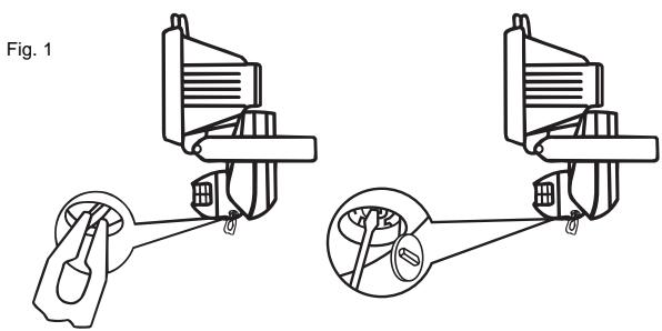
- Rotate the coding dials gently with a screwdriver, adjust them to your desires positions (See Fig. 2).
- Put the rubber cap back.
Fig. 2
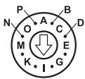
System Channel (house channel)
Note: System channel (or house channel) and unit channel have each 16 sets coding that provide flexible combination capability a total of 256 (16x16) different combinations.
- Make sure the arrowheads are adjusted to the proper positions.
- Make sure the transmitter and receiver are set with the same channel i.e. adjusting two units' system channel (or house channel) to position "1" and the unit channel to position "9".
INSTALLATION
A. Helpful Tips For a Better Transmission
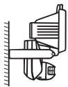
- In order to obtain the best transmission and reception performances, suggest to install Transmitter LU 102/180 HF at least one meter high from floor since ground is the best wave absorber. The higher of mounting position is, the better of detection result obtains.
- Transmitter LU 102/180 HF needs to warm up at least 2 minutes after powers on that assures Transmitter LU 102/180 HF to work steadily.
- Keep Transmitter LU 102/180 HF being located from surrounding conductive devices, such as aluminum reinforced UPVC window and door, metallic plate, and electric cables, at least one meter away.
- Avoid installing LU 102/180 HF on the thick wall or fence that blocks wave transmission and shortens the remote controlling distance.
- Keep the valid detection coverage of transmitter fully cleaned. And the surrounding space, respectively in 3 meters from the location of transmitter, having no other device that may receive the electric wave from Transmitter LU 102/180 HF.
- During installation, do not change or move antenna inside Transmitter LU 102/180 HF.
- During installation, keep electric cable from nearing to antenna that would cause radio waves interference.
- Avoid testing Transmitter LU 102/180 HF by holding on hands, do install it on the wall or ceiling since the human body is one kind of antenna that would cause interference to wirefree device.
During installation, make sure the combining receiver at least 2 meters away from other receivers to avoid shortening the remote control distance.
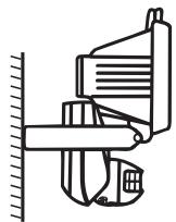
B. Select a Proper Location
1. Detection range
- Choose a proper installation position for Transmitter LU 102/180 HF where can work excellently with the combining Receiver.
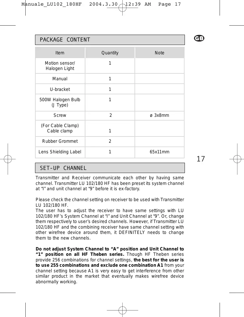
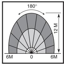
- Transmitter LU 102/180 HF can be mounted on the wall or the ceiling. The best installation heights is in 2-2.4M, the maximum detectable coverage is in 180°, 12M (See Fig. 3).
- The sensor head of transmitter can be adjustable downward. To adjust sensor head downward will reduce detection coverage. Followings are the detection patterns in different angles.
(1) Sensor head in horizontal position (See Fig. 3).
20
Fig. 3
natural_image
Pure mechanical diagram showing a lever mechanism without any text, numbers, or symbolsTop view
Side view

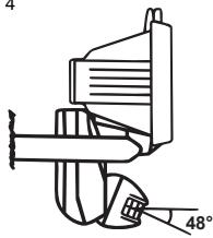
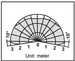
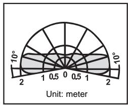
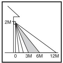
(2) Sensor head is adjustable downward to maximum angle 48^ (See Fig. 4).
Fig. 4
Top view
radar
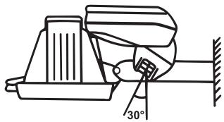
| Angle (°) | Value | |-----------|-------| | 0 | 0 | | 3 | 0 | | 6 | 0 | | 9 | 0 | | 12 | 0 | | 15 | 0 | | 18 | 0 | | 21 | 0 | | 24 | 0 | | 27 | 0 | | 30 | 0 | | 33 | 0 | | 36 | 0 | | 39 | 0 | | 42 | 0 | | 45 | 0 | | 48 | 0 | | 51 | 0 | | 54 | 0 | | 57 | 0 | | 60 | 0 | | 63 | 0 | | 66 | 0 | | 69 | 0 | | 72 | 0 | | 75 | 0 | | 78 | 0 | | 81 | 0 | | 84 | 0 | | 87 | 0 | | 90 | 0 | | 93 | 0 | | 96 | 0 | | 99 | 0 | Unit: meter(3) The 500W halogen light of Transmitter LU 102/180 HF is facing down and the sensor head is 30^ forward (See Fig. 5).

Fig. 5
Vue de haut
2. Avoid Nuisance Triggering
Transmitter LU 102/180 HF can be activated by any large animal, light reflective surface, heat source, or a moving object. The following guidelines will help you avoid nuisance triggering.
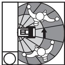
- Avoid the object moving directly toward the motion detector that brings the less sensitivity of detection. Have the object move across the pattern zone that brings more sensitivity of detection (See Fig. 6).
21
Fig. 6
flowchart
graph TD
    A["Start"] --> B["Process Unit"]
    B --> C{Decision}
    C -->|Yes| D["Output"]
    C -->|No| E["Feedback Loop"]
    E --> B
    style A fill:#f9f,stroke:#333
    style B fill:#ccf,stroke:#333
    style C fill:#cfc,stroke:#333
More sensitive by crossing the motion sensor
natural_image
Diagram of a radar or optical system with a central device and surrounding components (no text or symbols)Less sensitive by directly moving toward the motion sensor
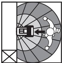
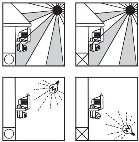
- Do not aim the sensor toward any kind of lighting sources (See Fig. 7).
Fig. 7
22
- Avoid aiming the sensor toward object that moves in the wind, such as bushes or lawn decorations (See Fig. 8).
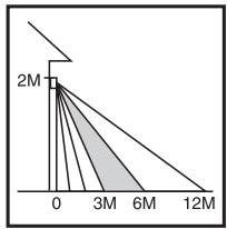
- Avoid mounting the sensor nearing any heat source, such as heating vent, air conditioner, dryer vent or the lighting device (See Fig. 9).
- Avoid having the sensor toward the area or the object whose surfaces is highly reflective or is subject to rapid changing in temperature, such as the pool, etc.
Fig. 8
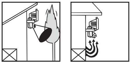
Fig. 9
3. Installation procedure
Note: Before starting to install Transmitter LU 102/180 HF, please test and make sure Transmitter LU 102/180 HF and the combining receiver can work normally in the selected zone.
- Turn power off before installing Transmitter LU 102/180 HF.
- Read the Instruction Manual carefully before proceeding.
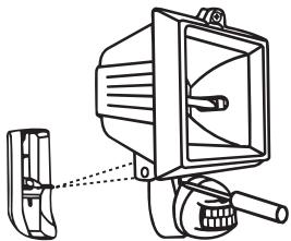
- Loosen the screws of the front case with a screwdriver and the screws will not fall down, will stay at front case's screw holes (See Fig. 10).

natural_image
Technical line drawing of a mechanical device with no visible text or symbolsFig. 10
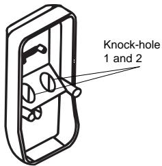
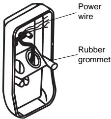
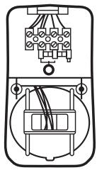
- Break the knock-hole of the back case (knock-hole 1 or knock-hole 2 as per your requirement) of the junction box. Fix the rubber grommet to the knock-hole and have the power wire through the knock-hole (See Fig.11).
Fig. 11
23
- Connect wires as per wiring diagram (See Fig. 12).
Fig. 12
natural_image
Pure electrical connector diagram without any text, numbers, or symbols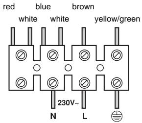
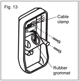
- After wires connection, fix the wires with cable clamp (See Fig. 13).
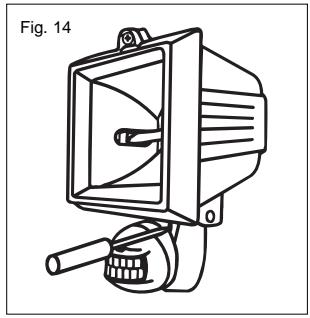
- Cover the front case and screw it up (See Fig. 14).
natural_image
Line drawing of a mechanical device labeled Fig. 14, showing a speaker with a bell and handle (no text or symbols on the device itself)- Fix the metallic bracket of 500W halogen light to the desired position with two screws (See Fig. 15).
24
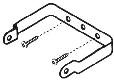
natural_image
Technical line drawing of a mechanical bracket with two screws inserted (no text or symbols)Fig. 15
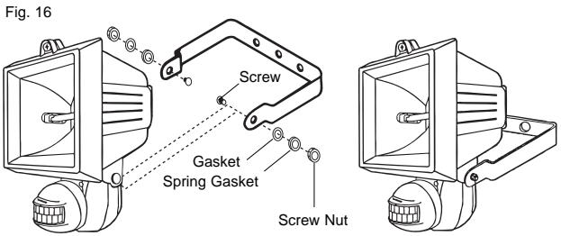
- Fix the body (sensor with halogen light) onto the mounting bracket (See Fig.16).
TEST AND ADJUSTMENT
GB
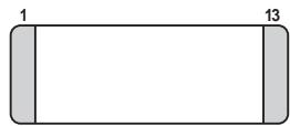
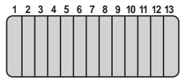
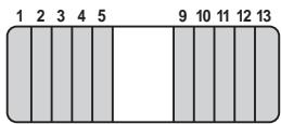
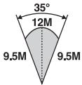
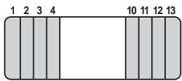
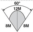
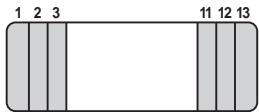
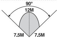
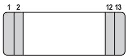
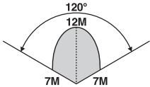
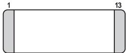
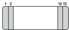
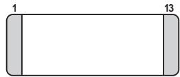
A. Usage of lens shielding label
In order to reduce detection coverage, you can use lens label, which is supplied with this instruction manual to cover transmitter's lens. Fig. 17 shows various detecting patterns while use the lens label in different
Fig. 17
natural_image
Simple rectangular shape with two side bars labeled 1 and 13, no text or symbols inside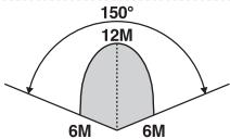
25
B. Indicator (LED) Function
LED is mainly designed as the indicator of Walk Test.
When environment is applicable for LUX, trigger the transmitter LU 102/180 HF, LED of LU 102/180 HF turns on for about 5 seconds and turns off then. At the same time, the load controlled by LU 102/180 HF turns on and turns off too. The load's light-up time is decided by the time set of the Transmitter LU 102/180 HF. After time set reaches, LU 102/180 HF can be re-triggered and LED may light on for about 5 seconds and light off. Before time set reaches, re-trigger the sensor, the combining receiver is able to receive the signal and time set re-count then, but LED does not light on again.
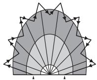
C. Walk Test
LU 102/180 HF automatically works when turns power on.
If it is necessary, you can use Walk Test to test and adjust the detection coverage of Transmitter LU 102/180 HF, that helps to make it working as you required. Before the test, adjust LUX to “ ✉”, Meter to “+”, Time to “-”, then you can start Walk Test (See Fig. 18).
26
Fig. 18
natural_image
Geometric fan-shaped diagram with radial lines and triangular elements, no text or symbols presentStart
Finish
Procedure of Walk Test:
- Aim the transmitter across the traffic pattern where you want to detect.
- Turn power on.
- Warm up Transmitter LU 102/180 HF for at least about 2 minutes.
-
Make sure Transmitter LU 102/180 HF and the combining receiver have been set with same channel.
-
Have someone walk across the pattern from outside of coverage until light turns on.
- When sensor is triggered at first time, LED will turn on and either one of Receiver will receive the transmission signal.
- The detection zone is adjustable by adjusting meter and sensor head.
- Repeat step 5 to step 7 until detection coverage zone meets your requirement.
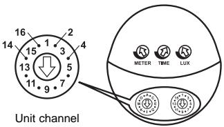
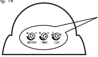
D. LUX, TIME, METER knobs (See Fig.19)
1. LUX.
- LUX is adjustable the range from about 5 LUX to . Since RF-160 Receiver is not controlled by LUX setting that means no matter how LUX is set, it will not influence the reception, it will work upon receiving the signal from LU 102/180 HF at any time.
- Set LUX knob to “ Ⓐ”, the sensor can operate the load in darkness only.
- Set LUX knob to “☀️”, the sensor can operate the load at any light level.
- Transmitter LU 102/180 HF has been preset at “☀️ Ⓐ” before ex-factory.
2. Time
- Time is adjustable from about 5 seconds minimum to about 5 minutes maximum by rotating the knob from “_” to “+”.
- Time setting decides how long the load of receiver would turn on.
- Transmitter LU 102/180 HF has been preset to “_” before ex-factory.
3. Meter
- Setting knob to “_” sensor detects the smallest “Field of View”.
- Setting knob to “+” sensor detects the largest “Field of View”.
- Transmitter LU102-180HF has been preset at “+” before ex-factory.
Fig. 19

METER

TIME

LUX

OPERATION
Responding Table of ON/OFF Signals
Transmitter and Receiver inter work by means of sending ON or OFF signal from a Transmitter to its combining Receiver and correspondingly a Receiver receives the signal from the combining Transmitter and reacts to the signal received. Following is the echoic table between transmitters and receivers of HF Theben series.
Transmitter
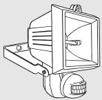
natural_image
Line drawing of a mechanical device with a central bracket and mounting base (no text or symbols)LU 102/180 HF
HF motion detector halogen light
Receiver
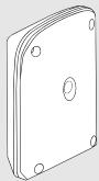
natural_image
Isometric line drawing of a rectangular electronic component with mounting holes (no text or symbols)REC 100 HF
HF outdoor/indoor receiver 10 A
Responding conditions as Transmitter sends the signal to Receiver
LU 102/180 HF sends ON and OFF signals to any one combining Receiver.
TROUBLE SHOOTING
When Transmitter LU 102/180 HF fails to work normally, check assumptive problems and suggested solutions in following table that will be hopeful to solve your problem.
| Problem | Possible Faulty Reason | Suggested Solution |
| Light does not turn on. | 1. Incorrect wiring or no power inputs. | 1. Make sure wirings are correct and has power input. |
| 2. Improper settings of LUX and METER. | 2. Adjust LUX to “+” and METER to “+”.Restore power and check if indicator (LED) turns on. | |
| 3. Beyond the detection zone. | 3. Make sure Transmitter LU101-180HF is mounted within the detection range. | |
| 4. Halogen light is bad. | 4. Make sure the halogen light functions normally. | |
| LED does not turn off. | 1. Nuisance triggering. | 1. Check if the ambient light reflects to the motion detector causing nuisance triggering. If so, adjust the direction of the Motion Sensor. |
| 2. Time set does not reach. | 2. Make sure time set reaches. |
SHIELDING LABEL
This label provides to cover the lens that would reduce detection coverage.
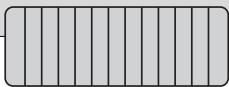
natural_image
Pure geometric pattern of vertical gray bars with no text or symbolsCE APPROVAL
CE 0122 ⚠
| N | DK | SF | IS | S |
| E | D | F | P | I |
| B | NL | L | GR | GB |
| IRL | CH | A |
Remarks:
- Theben HF products are allowed to sell to all EU and EFTA countries.
- The receiver complies with essential safety and radio frequency with CE (LVD & EMC) and R & TTE directives.
I
LU 102/180 HF
PROIETTORE CON RILEVATORE DI MOVIMENTO HF
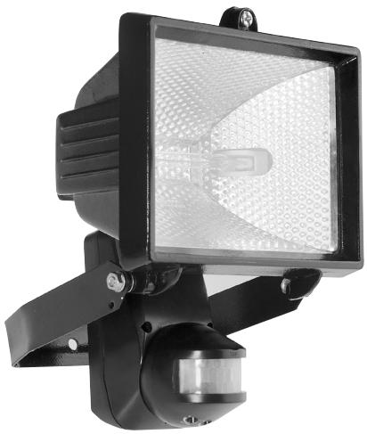
natural_image
Black and white photo of a modern streetlight fixture with a hexagonal patterned light source (no text or symbols visible)30
SPECIFICHE TECNICHE
natural_image
Pure mechanical diagram showing a lever mechanism without any text, numbers, or symbolsVista dall'alto
Vista di lato
natural_image
Diagram of a radar or optical system with a central device and surrounding components (no text or symbols)natural_image
Technical line drawing of a mechanical device with a bracket and lever (no text or symbols)natural_image
Line drawing of a mechanical device labeled Fig. 14, showing a speaker with a drum and handle (no text or symbols on the device itself)natural_image
Technical line drawing of a mechanical bracket with two screws and a dashed centerline (no text or symbols)natural_image
Line drawing of a mechanical device with a central bracket and mounting base (no text or symbols)TEST E REGOLAZIONE
natural_image
Simple diagram of a rectangular shape with labeled dimensions (1, 2, 12, 13) and no internal text or symbols.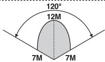
natural_image
Simple rectangular shape with two side bars, no text or symbols present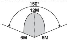
B. Funzione LED
natural_image
Symmetrical fan-like geometric pattern with radial lines and arrowheads, no text or symbols presentPartenza
Arrivo
natural_image
Technical line drawing of a mechanical device with no visible text or symbolsLU 102/180 HF
natural_image
Isometric line drawing of a rectangular electronic component with mounting holes (no text or symbols)REC 100 HF
Ricevitore HF esterno / interno 10 A
natural_image
Pure geometric pattern of vertical gray bars with no text or symbolsOMOLOGAZIONE C€
Nota:

- TEST ET REGLAGE
- Fonction LED
- HOMOLOGATION C€
- Remarques:
- TECHNICAL SPECIFICATIONS
- SET-UP CHANNEL
- INSTALLATION
- Helpful Tips For a Better Transmission
- Select a Proper Location
- Detection range
- Avoid Nuisance Triggering
- Installation procedure
- TEST AND ADJUSTMENT
- Usage of lens shielding label
- Indicator (LED) Function
- Walk Test
- Procedure of Walk Test:
- LUX, TIME, METER knobs (See Fig.19)
- LUX.
- Time
- Meter
- OPERATION
- Responding Table of ON/OFF Signals
- Responding conditions as Transmitter sends the signal to Receiver
- TROUBLE SHOOTING
- SHIELDING LABEL
- CE APPROVAL
- CE 0122 ⚠
- Remarks:
- SPECIFICHE TECNICHE
- TEST E REGOLAZIONE
- Funzione LED
- OMOLOGAZIONE C€
- Nota:
Brand : THEBEN
Model : LU 102-180
Category : Motion detectors