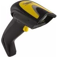
WLS9600 - Barcode Reader Wasp - Free user manual and instructions
Find the device manual for free WLS9600 Wasp in PDF.


| Product Type | Barcode Reader |
| Brand | Wasp |
| Model | WLS9600 |
| Dimensions (W x D x H) | Approx. 6.5 x 4.0 x 2.0 inches (165 x 102 x 51 mm) |
| Weight | Approx. 5.6 oz (160 g) |
| Power Source | USB bus-powered or external power adapter (5V DC) |
| Scan Engine | Laser or linear imager (typical 1D barcode support) |
| Scan Speed | Up to 100 scans per second |
| Barcode Symbologies | UPC, EAN, Code 128, Code 39, Interleaved 2 of 5, and many more |
| Interface | USB (HID keyboard or virtual COM port), optional RS232 |
| Operating Range | Up to 12 inches (30 cm) for typical barcodes |
| Operating Temperature | 32°F to 104°F (0°C to 40°C) |
| Storage Temperature | -4°F to 140°F (-20°C to 60°C) |
| Humidity | 5% to 95% non-condensing |
| Drop Resistance | Designed to withstand drops from 5 feet (1.5 m) |
| Cable Length | Standard 6 feet (1.8 m) USB cable |
| LED Indicators | Good read, power, and status LEDs |
| Beeper | Configurable for good read and error tones |
| Cleaning | Wipe with a soft, damp cloth; avoid abrasive cleaners |
| Maintenance | Keep optics clean; replace cable if damaged |
| Safety Certifications | CE, FCC Class B, RoHS |
| Spare Parts | Replacement USB cables, power adapters, and stands available |
| Repairability | User-serviceable: cable replacement; other repairs by qualified service center |
| Warranty | 1 year limited warranty |
Frequently Asked Questions - WLS9600 Wasp
User questions about WLS9600 Wasp
0 question about this device. Answer the ones you know or ask your own.
Ask a new question about this device
Download the instructions for your Barcode Reader in PDF format for free! Find your manual WLS9600 - Wasp and take your electronic device back in hand. On this page are published all the documents necessary for the use of your device. WLS9600 by Wasp.
USER MANUAL WLS9600 Wasp
natural_image
Black and yellow barcode scanner with no visible text or symbols on the device bodyProduct Reference Guide
Wasp Barcode Technologies
1400 10th Street
Plano, Texas USA 75074
Tel. 214-547-4100
Tel. 214-547-4101
©2000-2014 Wasp Barcode Technologies, Inc. (an unpublished work provided under license)
Patents
This product may be covered by one or more of the following patents:
Design Patents: CN ZL200830142386.5; CN ZL200930006852.1; EP870787; USD599799; USD606076.
Utility Patents: EP0789315B1; EP1128314B1; EP1128315B1; EP1396811B1; EP1413971B1;
EP1942442B1; US5481098; US5493108; US5992740; US6454168; US6494376; US6517003;
US6561427; US6808114; US6997385; US7387246
Additional patents pending.
Table of Contents
INTRODUCTION .... 1
About this Manual 1
Overview 1
Manual Conventions 2
References 2
Technical Support 2
Wasp Website Support 2
Telephone Technical Support 2
About the Reader 3
Programming the Reader 3
Configuration Methods 3
SETUP 5
Unpacking 5
Setting Up the Reader .... 5
Installing the Interface Cable 6
Interface Selection 8
Setting the Interface 8
Customizing Configuration Settings 12
Configure Interface Settings 12
Global Interface Features 12
Configuring Other Features 12
Software Version Transmission 12
Resetting the Product Configuration to Defaults 13
CONFIGURATION USING BARCODES 15
Configuration Parameters 15
Reading Configuration Barcodes 16
GLOBAL INTERFACE FEATURES 17
Host Commands — Obey/Ignore ....17
USB Suspend Mode 17
RS-232 ONLY Interface 19
Baud Rate 20
Data Bits 21
Stop Bits 21
Parity 22
Handshaking Control 23
RS-232/USB-Com Interfaces.... 24
Intercharacter Delay 25
Beep On ASCII BEL 25
Beep On Not on File 26
ACK NAK Options 27
ACK Character 28
NAK Character 28
ACK NAK Timeout Value 29
ACK NAK Retry Count 29
ACK NAK Error Handling 30
Indicate Transmission Failure 30
Disable Character 31
Enable Character 31
Keyboard Interface.... 33
Country Mode 34
Caps Lock State 37
Numlock 38
Send Control Characters 39
Wedge Quiet Interval 40
Intercharacter Delay 41
Intercode Delay 42
USB Keyboard Speed 43
USB Keyboard Numeric Keypad 44
USB-OEM Interface 45
USB-OEM Device Usage 46
Interface Options 46
Wand Emulation Interface 47
Wand Signal Speed 48
Wand Polarity 48
Wand Idle State 49
Transmit Noise 49
Label Symbology Conversion 50
Data Format 51
Global Prefix/Suffix 52
Global AIM ID 53
GS1-128 AIM ID 54
Label ID 55
Label ID: Pre-loaded Sets 55
Label ID: Set Individually Per Symbology 55
Label ID Control 56
Label ID Symbology Selection 57
Set Global Mid Label ID Characters 63
Case Conversion 64
Character Conversion 64
Reading Parameters 65
Double Read Timeout 66
Label Gone Timeout 67
LED AND BEEPER INDICATORS 68
Power On Alert 68
Good Read: When to Indicate 68
Good Read Beep Type 69
Good Read Beep Frequency 69
Good Read Beep Length 70
Good Read Beep Volume 71
Good Read LED Duration 72
SCANNING FEATURES 73
Scan Mode 73
Scanning Active Time 74
Flash On Time 74
Flash Off Time 75
Green Spot Duration 75
Code Selection 77
DISABLE ALL SYMBOLOGIES 78
CODE EAN/UPC 79
Coupon Control 79
UPC-A 80
UPC-A Enable/Disable 80
UPC-A Check Character Transmission 80
Expand UPC-A to EAN-13 81
UPC-A Number System Character Transmission 81
UPC-A Minimum Reads 82
UPC-E 83
UPC-E Enable/Disable 83
UPC-E Check Character Transmission 83
Expand UPC-E to EAN-13 84
Expand UPC-E to UPC-A 84
UPC-E Number System Character Transmission 85
UPC-E Minimum Reads 85
GTIN FORMATTING 86
EAN 13 (JAN 13) 87
EAN 13 Enable/Disable 87
EAN 13 Check Character Transmission ....87
EAN-13 Flag 1 Character 88
EAN-13 ISBN Conversion 88
EAN 13 Minimum Reads 89
ISSN 90
ISSN Enable/Disable 90
EAN 8 (JAN 8) 91
EAN 8 Enable/Disable 91
EAN 8 Check Character Transmission ....91
Expand EAN 8 to EAN 13 92
EAN 8 Minimum Reads 92
UPC/EAN GLOBAL SETTINGS 93
UPC/EAN Decoding Level 93
UPC/EAN Correlation 94
UPC/EAN Price Weight Check 94
In-Store Minimum Reads 95
ADD-ONS 96
Optional Add-ons 96
Optional Add-On Timer 97
Optional GS1-128 Add-On Timer 100
P2 Add-Ons Minimum Reads 103
P5 Add-Ons Minimum Reads 104
GS1-128 Add-Ons Minimum Reads 105
CODE 39 106
Code 39 Enable/Disable 106
Code 39 Check Character Calculation ....106
Code 39 Check Character Transmission 107
Code 39 Start/Stop Character Transmission 108
Code 39 Full ASCII 108
Code 39 Quiet Zones 109
Code 39 Minimum Reads 110
Code 39 Decoding Level 111
Code 39 Length Control 112
Code 39 Set Length 1 113
Code 39 Set Length 2 114
Code 39 Interdigit Ratio 115
Code 39 Character Correlation .... 117
Code 39 Stitching 117
CODE 32 (ITAL PHARMACEUTICAL CODE) 118
Code 32 Enable/Disable 118
Code 32 Feature Setting Exceptions 118
Code 32 Check Char Transmission 119
Code 32 Start/Stop Character Transmission 119
CODE 39 CIP (FRENCH PHARMACEUTICAL) 120
Code 39 CIP Enable/Disable 120
CODE 128 121
Code 128 Enable/Disable 121
Expand Code 128 to Code 39 121
Code 128 Check Character Transmission 122
Code 128 Function Character Transmission 122
Code 128 Sub-Code Change Transmission 123
Code 128 Quiet Zones 124
Code 128 Minimum Reads 125
Code 128 Decoding Level 126
Code 128 Length Control 127
Code 128 Set Length 1 128
Code 128 Set Length 2 129
Code 128 Character Correlation 130
Code 128 Stitching 130
GS1-128 131
GS1-128 Enable 131
12 of 5 Enable/Disable 139
12 of 5 Check Character Calculation .... 139
12 of 5 Check Character Transmission 140
12 of 5 Minimum Reads 141
2 of 5 Decoding Level 142
12 of 5 Length Control 143
12 of 5 Set Length 1 144
12 of 5 Set Length 2 145
I 2 of 5 Character Correlation .... 146
12 of 5 Stitching .... 146
FOLLETT 2 OF 5 147
Follett 2 of 5 Enable/Disable 147
INTERLEAVED 2 OF 5 CIP HR 147
Interleaved 2 of 5 CIP HR Enable/Disable 147
STANDARD 2 OF 5 148
Standard 2 of 5 Enable/Disable 148
Standard 2 of 5 Check Character Calculation 148
Standard 2 of 5 Check Character Transmission 149
Standard 2 of 5 Minimum Reads 149
Standard 2 of 5 Decoding Level 150
Standard 2 of 5 Length Control 150
Standard 2 of 5 Set Length 1 151
Standard 2 of 5 Set Length 2 152
Standard 2 of 5 Character Correlation .... 153
Standard 2 of 5 Stitching 153
INDUSTRIAL 2 OF 5 154
Industrial 2 of 5 Enable/Disable 154
Industrial 2 of 5 Check Character Calculation ....154
Industrial 2 of 5 Check Character Transmission .... 155
Industrial 2 of 5 Length Control 155
Industrial 2 of 5 Set Length 1 156
Industrial 2 of 5 Set Length 2 157
Industrial 2 of 5 Minimum Reads 158
Industrial 2 of 5 Stitching 158
Industrial 2 of 5 Character Correlation 159
CODE IATA 160
IATA Enable/Disable 160
IATA Check Character Transmission 160
CHINA POSTAL CODE 161
China Postal Code Enable/Disable 161
China Postal Code Check Character Calculation 161
China Postal Code Minimum Reads 162
China Postal Code Decoding Level 162
China Postal Code Length Control 163
China Postal Code Set Length 1 164
China Postal Code Set Length 2 165
China Postal Code Character Correlation 166
China Postal Code Stitching 166
CODABAR 167
Codabar Enable/Disable 167
Codabar Check Character Calculation 167
Codabar Check Character Transmission 168
Codabar Start/Stop Character Transmission 168
Codabar Start/Stop Character Set 169
Codabar Start/Stop Character Match 169
Codabar Quiet Zones 170
Codabar Minimum Reads 171
Codabar Decoding Level 172
Codabar Length Control 173
Codabar Set Length 1 174
Codabar Set Length 2 175
Codabar Interdigit Ratio 176
Codabar Character Correlation 178
Codabar Stitching 178
ABC CODABAR 179
ABC Codabar Enable/Disable 179
ABC Codabar Concatenation Mode 179
ABC Codabar Dynamic Concatenation Timeout 180
ABC Codabar Force Concatenation 181
CODE 11 182
Code 11 Enable/Disable 182
Code 11 Check Character Calculation 182
Code 11 Check Character Transmission 183
Code 11 Minimum Reads 183
Code 11 Length Control 184
Code 11 Set Length 1 185
Code 11 Set Length 2 186
Code 11 Interdigit Ratio 187
Code 11 Decoding Level 189
Code 11 Character Correlation 190
Code 11 Stitching 190
GS1 DATABAR™ OMNIDIRECTIONAL 191
GS1 DataBar™ Omnidirectional Enable/Disable 191
GS1 DataBar™ Omnidirectional GS1-128 Emulation 191
GS1 DataBar™ Omnidirectional Minimum Reads 192
GS1 DATABAR™ EXPANDED 193
GS1 DataBar™ Expanded Enable/Disable 193
GS1 DataBar™ Expanded GS1-128 Emulation 193
GS1 DataBar™ Expanded Minimum Reads 194
GS1 DataBar™ Expanded Length Control 194
GS1 DataBar™ Expanded Set Length 1 195
GS1 DataBar™ Expanded Set Length 2 196
GS1 DATABAR™ LIMITED 197
GS1 DataBar™ Limited Enable/Disable 197
GS1 DataBar™ Limited GS1-128 Emulation 197
GS1 DataBar™ Limited Minimum Reads 198
CODE 93 199
Code 93 Enable/Disable 199
Code 93 Check Character Calculation 199
Code 93 Check Character Transmission 200
Code 93 Length Control 200
Code 93 Set Length 1 201
Code 93 Set Length 2 202
Code 93 Minimum Reads 203
Code 93 Decoding Level 204
Code 93 Quiet Zones 205
Code 93 Stitching 206
Code 93 Character Correlation 206
MSI 207
MSI Enable/Disable 207
MSI Check Character Calculation 207
MSI Check Character Transmission 208
MSI Length Control 208
MSI Set Length 1 209
MSI Set Length 2 210
MSI Minimum Reads 211
MSI Decoding Level 212
PLESSEY 213
Plessey Enable/Disable 213
Plessey Check Character Calculation 214
Plessey Check Character Transmission 214
Plessey Length Control 215
Plessey Set Length 1 216
Plessey Set Length 2 217
Plessey Minimum Reads 218
Plessey Decoding Level 219
Plessey Stitching 220
Plessey Character Correlation 220
CODE 4 221
Code 4 and Code 5 Minimum Reads 225
Laser Features 227
Laser Scan Angle 228
Laser Idle Mode 228
Bi-Directional Read Decoding 229
Always On Scan Mode Timeout 230
REFERENCES.... 231
RS-232 Parameters 231
RS-232 Only 231
RS-232/USB COM Parameters 232
Keyboard Interface 239
Wedge Quiet Interval 239
Intercharacter Delay 240
Intercode Delay 241
Symbologies 242
Decoding Level 242
Set Length 242
Data Editing 244
Global Prefix/Suffix 245
Global AIM ID 246
Label ID 247
Character Conversion 251
Reading Parameters 252
Label Gone Timeout 252
Good Read LED Duration 253
Scanning Features 254
Scan Mode 254
Scanning Active Time 255
Flash On Time 256
Flash Off Time 257
Technical Specifications 259
Standard Cable Pinouts 261
LED and Beeper Indications 262
Error Codes 263
Standard Defaults 265
Sample Barcodes 275
Keypad 279
Scancode Tables 283
Control Character Emulation 283
Single Press and Release Keys 283
Interface Type PC AT PS/2, USB-Keyboard or USB-Keyboard for APPLE 284
Interface type PC AT PS/2 Alt Mode or USB-Keyboard Alt Mode 286
Digital Interface 288
IBM31xx 102-key 289
IBM XT 290
Microsoft Windows Codepage 1252 291
NOTES
Chapter 1 Introduction
About this Manual
This Product Reference Guide (PRG) is provided for users seeking advanced technical information, including connection, programming, maintenance and specifications. The Quick Reference Guide (QRG) and other publications associated with this product are downloadable free of charge from the website listed on the back cover of this manual.
Overview
Chapter 1, (this chapter) presents information about manual conventions, and an overview of the reader, its features and operation.
Chapter 2, Setup presents information about unpacking, cable connection information and setting up the reader.
Chapter 3, Configuration Using Barcodes provides instructions and barcode labels for customizing your reader. There are different sections for interface types, general features, data formatting, symbology-specific and model-specific features.
Chapter 4, Laser Features describes options and programming specific to laser models.
Chapter 5, References provides background information and detailed instructions for more complex programming items.
Appendix A, Technical Specifications lists physical and performance characteristics, as well as environmental and regulatory specifications. It also provides standard cable pin-outs and LED/Beeper functions.
Appendix B, Standard Defaults references common factory default settings for reader features and options.
Appendix C, Sample Barcodes offers sample barcodes of several common symbologies.
Appendix D, Keypad includes numeric barcodes to be scanned for certain parameter settings.
Appendix E, Scancode Tables lists control character emulation information for Wedge and USB Keyboard interfaces.
Manual Conventions
The following conventions are used in this document:
The symbols listed below are used in this manual to notify the reader of key issues or procedures that must be observed when using the reader:

Notes contain information necessary for properly diagnosing, repairing and operating the reader.

The CAUTION symbol advises you of actions that could damage equipment or property.
CAUTION
References
Current versions of this Product Reference Guide (PRG), Quick Reference Guide (QRG), and any other manuals, instruction sheets and utilities for this product can be downloaded from the website listed below. Alternatively, printed copies or product support CDs for most products can be purchased through your Wasp reseller.
Technical Support
Wasp Website Support
The Wasp website (www.waspbarcode.com) is the complete source for technical support and information for Wasp products. The site offers product support, warranty information, product manuals, product tech notes, software updates, demos, and instructions for returning products for repair.
Telephone Technical Support
If you do not have internet or email access, you may contact Wasp Barcode Technologies technical support at 214-547-4100, or check the back cover of this manual for more contact information.
About the Reader
Typically, units are factory-programmed for the most common terminal and communications settings. If you need to modify any programmable settings, custom configuration can be accomplished by scanning the programming barcodes within this guide.
The WLS9600 model has a Laser scan engine. Advancements in the LED technology used in the imager-based readers significantly improve the illumination of the target field of view, resulting in higher scan efficiency. Whether used in Single Trigger or Continuous Mode, the ergonomic design of the reader will help to promote comfortable handling during extended periods of use.
See "Interface Selection" on page 8 for a listing and descriptions of available interface sets by model type.
Programming the Reader
Configuration Methods
Programming Barcodes
The reader is factory-configured with a standard set of default features. After scanning the interface barcode, you can select other options and customize your reader through use of the instructions and programming barcode labels available in the corresponding features section for your interface. Customizable settings for many features are found in "Configuration Using Barcodes" starting on page 15.
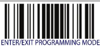
Some programming labels, like "Restore Custom Defaults" on page 13, require only the scan of the single label to enact the change. Most, however, require the reader to be placed in Programming Mode prior to scanning them. Scan an ENTER/EXIT barcode once to enter Programming Mode. Once the reader is in Programming Mode, scan a number of parameter settings before scanning the ENTER/EXIT barcode a second time, which will then accept your changes, exit Programming Mode and return the reader to normal operation.

There are some exceptions to the typical programming sequence described above. Please read the description and setting instructions carefully when configuring each programmable feature.
NOTES
Chapter 2 Setup
Unpacking
Check carefully to ensure the reader and any accessories ordered are present and undamaged. If any damage occurred during shipment, contact Wasp Technical Support. Information is shown on page 2.
KEEP THE PACKAGING. Should the unit ever require service, it should be returned in its original shipping container.
Setting Up the Reader
Follow the steps provided in this section to connect and get your reader up and communicating with its host.
- Begin by Installing the Interface Cable.
- Go to Interface Selection and set the desired interface.
- Configure Interface Settings (only if not using factory settings for that interface)
- Go to Configuring Other Features (if modifications are needed from factory settings)
Installing the Interface Cable
For Corded versions, connect the reader cable by inserting the cable into the handle as shown in Figure 1. To remove it, insert a paper clip into the release aperture, then unplug the cable.
Figure 1. Connect/disconnect the cable

natural_image
Technical line drawing of a hairdryer tool with two views showing internal components and adjustment arrows (no text or symbols)RS-232 Serial Connection

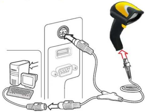
Turn off power to the terminal/PC and connect the reader to the terminal/PC serial port via the RS-232 cable as shown in Figure 2. If the terminal will not support POT (Power Off the Terminal) to supply reader power, use the approved power supply (AC Adapter). Plug the AC Adapter barrel connector into the socket on the RS-232 cable connector and the AC Adapter plug into a standard power outlet.
Figure 2. RS-232 Connection

Keyboard Wedge Connection

The Keyboard Wedge cable has a 'Y' connection from the reader. Connect the female to the male end from the keyboard and the remaining end at the keyboard port at the terminal/PC. Reference Figure 3.
Figure 3. Keyboard Wedge Interface connection
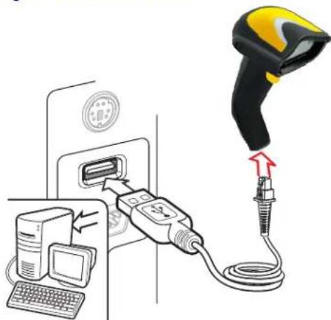
USB Connection

Connect the reader to a USB port on the terminal/PC using the correct USB cable for the interface type you ordered. Reference Figure 4.
Figure 4. USB connection
Other connection types are described below and illustrated in Figure 5.
Figure 5. Other Interface Connections


Specific cables are required for connection to different hosts. The connectors illustrated above are examples only. Actual connectors may vary from those illustrated, but the steps to connect the reader remain the same.
Interface Selection
Upon completing the physical connection between the reader and its host, proceed to Table 1 starting on page 9 to select the interface type the reader is connected to (for example: RS-232, Keyboard Wedge, USB, etc.). Scan the appropriate barcode in that section to configure your system's correct interface type.
The reader will support one of the following sets of host interfaces:
• RS-232 OPOS
USB
- Keyboard Wedge
- Wand Emulation
• R S - 2 3 2
Setting the Interface
Scan the programming barcode from this section which selects the appropriate interface type matching the system the reader will be connected to. Next, proceed to the corresponding section in this manual (also listed in Table 1 starting on page 9) to configure any desired settings and features associated with that interface.

Unlike some programming features and options, interface selections require that you scan only one programming barcode label. DO NOT scan an ENTER/EXIT barcode prior to scanning an interface selection barcode.
Some interfaces require the scanner to start in the disabled state when powered up. If additional scanner configuration is desired while in this state, pull the trigger and hold it for five seconds. The scanner will change to a state that allows programming with barcodes.
Table 1. Available Interfaces
| RS-232 | FEATURES | |
| RS-232 standard interface |  Select RS232-STD Select RS232-STD | Set RS-232 Interface Features starting on page 19 |
 Select RS232-WN Select RS232-WN | RS-232 Wincor-Nixdorf | |
| RS-232 for use with OPOS/UPOS/JavaPOS |  Select RS-232 OPOS Select RS-232 OPOS | |
 Select USB-COM-STDa Select USB-COM-STDa | USB Com to simulate RS-232 standard interface | |
| USB-OEM | FEATURES | |
 Select USB-OEM Select USB-OEM | USB-OEM(can be used for OPOS/UPOS/JavaPOS) | Set USB-OEM Interface Features starting on page 45 |
a. Download the correct USB Com driver from www.waspbarcode.com
| KEYBOARD | FEATURES | |
| AT, PS/2 25-286, 30-286, 50, 50Z, 60, 70, 80, 90 & 95 w/Standard Key Encoding |  Select KBD-AT Select KBD-AT | Set KEYBOARDWEDGEInterfaceFeaturesstarting onpage 33 |
 Select KBD-AT-NK Select KBD-AT-NK | Keyboard Wedge for IBM AT PS2 with standard key encoding but without external keyboard | |
| AT, PS/2 25-286, 30-286, 50, 50Z, 60, 70, 80, 90 & 95 w/Alternate Key |  Select KBD-AT-ALT Select KBD-AT-ALT | |
 Select KBD-AT-ALT-NK Select KBD-AT-ALT-NK | Keyboard Wedge for IBM AT PS2 with alternate key encoding but without external keyboard | |
| PC/XT w/Standard Key Encoding |  Select KBD-XT Select KBD-XT | |
 Select KBD-IBM-3153 Select KBD-IBM-3153 | Keyboard Wedge for IBM Terminal 3153 | |
| KEYBOARD (continued) | FEATURES | |
| Keyboard Wedge for IBM Terminals 31xx, 32xx, 34xx, 37xx make only keyboard |  Select KBD-IBM-M Select KBD-IBM-M | Set KEYBOARD WEDGE Interface Features starting on page 33 |
 Select KBD-IBM-MB Select KBD-IBM-MB | Keyboard Wedge for IBM Terminals 31xx, 32xx, 34xx, 37xx make break keyboard | |
| Keyboard Wedge for DIGITAL Terminals VT2xx, VT3xx, VT4xx |  Select KBD-DIG-VT Select KBD-DIG-VT | |
 Select USB Keyboard Select USB Keyboard | USB Keyboard with standard key encoding | |
| USB Keyboard with alternate key encoding |  Select USB Alternate Keyboard Select USB Alternate Keyboard | |
 Select USB-KBD-APPLE Select USB-KBD-APPLE | USB Keyboard for Apple computers | |
| WAND EMULATION FEATURES | ||
| Wand Emulation | Select WAND | Set WAND Interface Features starting on page 47 |
Customizing Configuration Settings
Configure Interface Settings
If after scanning the interface barcode from the previous table, your installation requires you to select options to further customize your reader, turn to the appropriate section for your interface type in "Configuration Using Barcodes" starting on page 15.
• "RS-232 ONLY Interface" on page 19
• "RS-232/USB-Com Interfaces" on page 24
- "Keyboard Interface" on page 33
- "USB-OEM Interface" on page 45
- "Wand Emulation Interface" on page 47
Global Interface Features
See "Global Interface Features" on page 17 for settings configurable by all interface types.
Configuring Other Features
If your installation requires different programming than the standard factory default settings, the following sections of this manual allow configuration of non-interface-specific settings you might require:
Reading Parameters: Reading Parameters include programming for scanning, beeper and LED indicators and other universal settings.
Code Selection: Includes options concerning the barcode label types (symbologies). These settings allow you to enable/disable symbologies, set label lengths, require check digit, etc.
Laser Features: Describes options and programming specific to laser models.
Software Version Transmission
The software version of the device can be transmitted over the RS-232 and Keyboard interfaces by scanning the following label.

Transmit Software Version
Resetting the Product Configuration to Defaults
If you aren't sure what programming options are in your imager, or you've changed some options and want to restore the Custom Default Configuration that may have been saved in the scanner, scan the Restore Custom Default Configuration barcode below. This will restore the custom configuration for the currently active interface.

Custom defaults are based on the interface type. Configure the imager for the correct interface before scanning this label.

Restore Custom Default Configuration
Restore Factory Configuration
If you want to restore the Factory Configuration for your imager, scan either the Restore USA Factory Configuration barcode or the Restore EU Factory Configuration barcode below. Both labels restore the scanner configuration to the factory settings, including the interface type. The USA label restores Label IDs to those historically used in the USA. The EU label restores Label IDs to those historically used in Europe. The Label ID sets for USA and EU are shown in the "Label ID" section on page 55 of this manual.

Restore USA Factory Configuration

Restore EU Factory Configuration
The programming items listed in the following sections show the factory default settings for each of the menu commands.
NOTES
Chapter 3
Configuration Using Barcodes
This and following sections provide programming barcodes to configure your reader by changing the default settings. For details about additional methods of programming, see Configuration Methods on page 3.

You must first enable your reader to read barcodes in order to use this section. If you have not done this, go to Setup, starting on page 5 and complete the appropriate procedure.
Configuration Parameters
Once the reader is set up, you can change the default parameters to meet your application needs. Refer to "Standard Defaults" starting on page 265 for initial configuration in order to set the default values and select the interface for your application.
The following configuration parameters are divided into logical groups, making it easy to find the desired function based on its reference group.
Interface Configuration:
• "RS-232 ONLY Interface" on page 19
• "RS-232/USB-Com Interfaces" on page 24
• "Keyboard Interface" on page 33
- "USB-OEM Interface" on page 45
• "Wand Emulation Interface" on page 47
Parameters common to all interface applications:
- "Data Format" on page 51 gives options to control the messages sent to the Host system.
- "Reading Parameters" on page 65 control various operating modes and indicators status functioning.
Symbology-specific parameters:
- "Code Selection" on page 77 provides configuration of a personalized mix of codes, code families and their options.
Model-specific parameters:
- "Laser Features" on page 227 provides options specific to laser models.
Reading Configuration Barcodes

You must first enable your reader to read barcodes in order to use this section. If you have not done this, go to Setup, starting on page 5 and complete the appropriate procedure.
To program features:
- Scan the ENTER/EXIT PROGRAMMING barcode, available at the top of each programming page, when applicable.
- Scan the barcode to set the desired programming feature. You may need to cover unused barcodes on the page, and possibly the facing page, to ensure that the reader reads only the barcode you intend to scan.
- If additional input parameters are needed, go to Appendix D, Keypad, and scan the appropriate characters from the keypad.

Additional information about many features can be found in the "References" chapter.
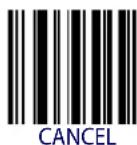
If you make a mistake before the last character, scan the CANCEL barcode to abort and not save the entry string. You can then start again at the beginning.
- Complete the programming sequence by scanning the ENTER/EXIT PROGRAMMING barcode to exit Programming Mode.
For detailed descriptions, programming information and examples for setting selected configuration items, see References, starting on page 231.

ENTER/EXIT PROGRAMMING MODE Host Commands — Obey/Ignore
GLOBAL INTERFACE FEATURES
The following interface features are configurable by all interface types.
Host Commands — Obey/Ignore
This option specifies whether the reader will obey or ignore host commands. When set to ignore, the reader will ignore all host commands except for those necessary for:
• service mode
- flash programming mode
- keeping the interface active
- transmission of labels.


Host Commands = Obey

Host Commands = Ignore
USB Suspend Mode
This setting enables/disables the ability of USB interfaces to enter suspend mode.

USB Suspend Mode = Disable

USB Suspend Mode = Enable
NOTES
RS-232 ONLY INTERFACE
| BAUD RATE on page 20 |
| DATA BITS on page 21 |
| STOP BITS on page 21 |
| PARITY on page 22 |
| HANDSHAKING CONTROL on page 23 |
Use the programming barcodes in this section if modifications to the standard RS-232 interface settings are necessary to meet your system's requirements. Additional settings which apply to both the RS-232 and USB interfaces are available in the next section, "RS-232/USB-Com Interfaces" starting on page 24.
Reference Appendix B, Standard Defaults for a listing of standard factory settings.
Baud Rate
See page 231 for information on this feature.
 Baud Rate = 1200 Baud Rate = 1200 | |
 Baud Rate = 2400 Baud Rate = 2400 | |
 Baud Rate = 4800 Baud Rate = 4800 | |
 Baud Rate = 9600 Baud Rate = 9600 |  |
 Baud Rate = 19,200 Baud Rate = 19,200 | |
 Baud Rate = 38,400 Baud Rate = 38,400 | |
 Baud Rate = 57,600 Baud Rate = 57,600 | |
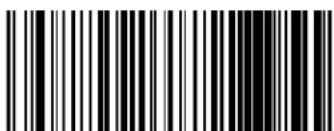 Baud Rate = 115,200 Baud Rate = 115,200 |

ENTER/EXIT PROGRAMMING MODE Data Bits
Data Bits
This parameter allows the reader to interface with devices requiring a 7-bit or 8-bit ASCII protocol for sending and receiving data.
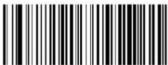 7 Data Bits 7 Data Bits | |
 8 Data Bits 8 Data Bits |  |
Stop Bits
Set the number of stop bits to match host device requirements. See page 231 for more information on this feature.
 |  1 Stop Bit 1 Stop Bit |
 2 Stop Bits 2 Stop Bits |
Parity
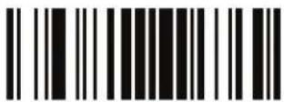
This feature specifies parity required for sending and receiving data. Select the parity type according to host device requirements. See page 231 for more information.


Parity = Even

Parity = None

Parity = Odd
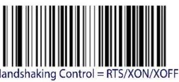
ENTER/EXIT PROGRAMMING MODE Handshaking Control
Handshaking Control
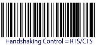
See page 231 for more information about this feature.
 |  |
| Handwriting control, H/C | |
 | |
 | |
| H | |
 | |
 | |
| Han |
RS-232/USB-COM INTERFACES
| INTERCHARACTER DELAY on page 25 |
| BEEP ON ASCII BEL on page 25 |
| BEEP ON NOT ON FILE on page 26 |
| ACK NAK OPTIONS on page 27 |
| ACK CHARACTER on page 28 |
| NAK CHARACTER on page 28 |
| ACK NAK TIMEOUT VALUE on page 29 |
| ACK NAK RETRY COUNT on page 29 |
| ACK NAK ERROR HANDLING on page 30 |
| INDICATE TRANSMISSION FAILURE on page 30 |
| DISABLE CHARACTER on page 31 |
| ENABLE CHARACTER on page 31 |
The programming barcodes in this chapter allow modifications to the standard RS-232 and USB-Com interfaces. Reference Appendix B, Standard Defaults for a listing of standard factory settings.

ENTER/EXIT PROGRAMMING MODE Intercharacter Delay
Intercharacter Delay
This parameter specifies the intercharacter delay between the end of one character and the beginning of the next. The delay can be set within a range of zero (0) to 990 milliseconds in 10ms increments. A setting of zero specifies no delay.
See page 232 for more information.
 Intercharacter Delay = No Delay Intercharacter Delay = No Delay | |
 Select Intercharacter Delay Setting Select Intercharacter Delay Setting | |
| Make a mistake? Scan the CANCEL barcode to abort and not save the entry string. You can then start again at the beginning. |  CANCEL CANCEL |
DEFAULT
00 = No Intercharacter Delay
Beep On ASCII BEL
When this parameter is enabled, the reader issues a beep when a

Beep On ASCII BEL = Disable


Beep On ASCII BEL = Enable
Beep On Not on File
This option enables/disables the action of the reader to sound a three beep sequence upon receiving a Not-On-File (NOF) host command.
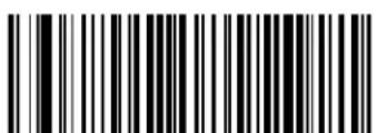
Beep On Not On File = Disable

Beep On Not On File = Enable

ENTER/EXIT PROGRAMMING MODE ACK NAK Options
ACK NAK Options
This enables/disables the ability of the reader to support the RS-232 ACK/NAK protocol. See page 233 for more information.
 | 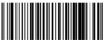 ACK/NAK Protocol = Disable ACK/NAK ACK/NAK Protocol = Disable ACK/NAK |
 ACK/NAK Protocol = Enable for label transmission ACK/NAK Protocol = Enable for label transmission | |
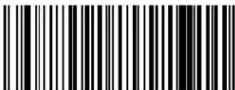 ACK/NAK Protocol = Enable for host-command acknowledge ACK/NAK Protocol = Enable for host-command acknowledge | |
 ACK/NAK Protocol = Enable for label transmission and host-command acknowledge ACK/NAK Protocol = Enable for label transmission and host-command acknowledge |
ACK Character
This setting specifies an ASCII character or hex value to be used as the ACK character. ASCII characters or any hex value from 0 to 0xFF can be selected. See page 233 for more information.

Setting to previously defined characters such as XON, XOFF, or host commands conflicts with normal operation of these characters. 8-bit data is not recognized when the optionData Bits has been set as 7 Data Bits.

DEFAULT
0x06 'ACK' Character
NAK Character
This setting specifies an ASCII character or hex value to be used as the NAK character. ASCII characters or any hex value from 0 to 0xFF can be selected. See page 234 for more information.

Setting to previously defined characters such as XON, XOFF, or host commands conflicts with normal operation of these characters. 8-bit data is not recognized when the option Data Bits has been set as 7 Data Bits.
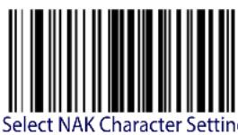
DEFAULT
0x15 'NAK' Character

ENTER/EXIT PROGRAMMING MODE ACK NAK Timeout Value
ACK NAK Timeout Value
This option specifies the amount of time the reader waits for an ACK character from the host following label transmission. The selectable timeout range is 200 milliseconds to 15,000ms (15 seconds) in 200ms increments. A selection of 0 disables the timeout.
See page 235 for more information on setting this feature.

Select ACK NAK Timeout Value Setting
Make a mistake? Scan the CANCEL barcode to abort and not save the entry string. You can then start again at the beginning.
CANCEL
DEFAULT
01 ACK NAK Timeout value is 200ms
ACK NAK Retry Count
This feature specifies the number of times the reader retries a label transmission due to a retry condition. The selectable range is from 1 to 254 retries. A selection of 0 disables the count, and a selection of 255 specifies unlimited retries. See page 236 for more information.

Select ACK NAK Retry Count Setting
Make a mistake? Scan the CANCEL barcode to abort and not save the entry string. You can then start again at the beginning.

CANCEL
DEFAULT
003 = 3 Retries
ACK NAK Error Handling
This feature specifies the method the reader uses to handle receive errors detected while waiting for an ACK character from the host.
 |  ACK NAK Error Handling = Ignore Errors Detected ACK NAK Error Handling = Ignore Errors Detected |
 ACK NAK Error Handling = Process Error as Valid ACK Character ACK NAK Error Handling = Process Error as Valid ACK Character | |
 ACK NAK Error Handling = Process Error as Valid NAK Character ACK NAK Error Handling = Process Error as Valid NAK Character |
Indicate Transmission Failure
This option enables/disables the reader's ability to sound an error beep to indicate a transmission failure while in ACK/NAK mode.
 Indicate Transmission Failure = Disable Indication Indicate Transmission Failure = Disable Indication | |
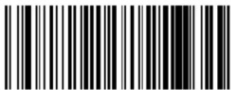 Indicate Transmission Failure = Enable Indication Indicate Transmission Failure = Enable Indication |  |
Disable Character
Specifies the value of the RS-232 host command used to disable the reader.
ASCII characters or any hex value from 0 to 0xFF can be selected.

Setting to previously defined characters such as XON, XOFF, or host commands conflicts with normal operation of these characters. 8-bit data is not recognized when the option Data Bits has been set as 7 Data Bits.
See page 237 for more information on setting this feature.

Select Disable Character Setting
DEFAULT
0x44 = Disable Character is 'D'
Enable Character
Specifies the value of the RS-232 host command used to enable the reader.
ASCII characters or any hex value from 0 to 0xFF can be selected.

Setting to previously defined characters such as XON, XOFF, or host commands conflicts with normal operation of these characters. 8-bit data is not recognized when the option Data Bits has been set as 7 Data Bits.
See page 238 in “References” for more information on setting this feature.

Select Enable Character Setting
DEFAULT
0x45 = Enable Character is 'E'
NOTES
KEYBOARD INTERFACE
| COUNTRY MODE on page 34 |
| CAPS LOCK STATE on page 37 |
| NUMLOCK on page 38 |
| SEND CONTROL CHARACTERS on page 39 |
| WEDGE QUIET INTERVAL on page 40 |
| INTERCHARACTER DELAY on page 41 |
| INTERCODE DELAY on page 42 |
| USB KEYBOARD SPEED on page 43 |
| USB KEYBOARD NUMERIC KEYPAD on page 44 |
Use the programming barcodes in this chapter to select options for USB Keyboard and Wedge Interfaces. Reference Appendix B, Standard Defaults for a listing of standard factory settings.
Information about control character emulation which applies to keyboard interfaces is listed in Appendix E, Scancode Tables.
Country Mode
This feature specifies the country/language supported by the keyboard.
Only the following interfaces support ALL Country Modes.
- USB Keyboard (without alternate key encoding)
- AT, PS/2 25-286, 30-286, 50, 50Z, 60, 70, 80, 90 & 95 w/Std Key Encoding
- Keyboard Wedge for IBM AT PS2 with standard key encoding but without external keyboard
- AT, PS/2 25-286, 30-286, 50, 50Z, 60, 70, 80, 90 & 95 without Alternate Key
- Keyboard Wedge for IBM AT PS2 without alternate key encoding but without external keyboard
- Bluetooth HID Profile
All other interfaces support ONLY the following Country Modes: U.S., Belgium, Britain, France, Germany, Italy, Spain, Sweden.


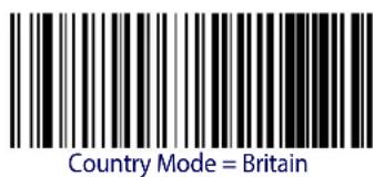

Supports only the interfaces listed in the Country Mode feature description.


ENTER/EXIT PROGRAMMING MODE Country Mode
Country Mode (continued)
 Country Mode = Denmark Country Mode = Denmark | Supports only the interfaces listed in the Country Mode feature description. |
 Country Mode = France Country Mode = France | |
 Country Mode = French Canadian Country Mode = French Canadian | |
 Country Mode = Germany Country Mode = Germany | |
 Country Mode = Hungary Country Mode = Hungary | Supports only the interfaces listed in the Country Mode feature description. |
 Country Mode = Italy Country Mode = Italy | |
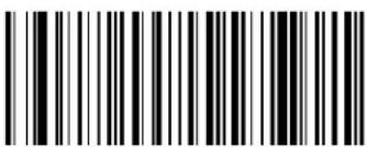 Country Mode = Japanese 106-key Country Mode = Japanese 106-key | Supports only the interfaces listed in the Country Mode feature description. |
 Country Mode = Lithuanian Country Mode = Lithuanian | |
| Supports only the interfaces listed in the Country Mode feature description. | 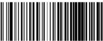 Country Mode = Norway Country Mode = Norway |
 Country Mode = Poland Country Mode = Poland | Supports only the interfaces listed in the Country Mode feature description. |
| Supports only the interfaces listed in the Country Mode feature description. |  Country Mode = Portugal Country Mode = Portugal |
 Country Mode = Romania Country Mode = Romania | Supports only the interfaces listed in the Country Mode feature description. |
| Supports only the interfaces listed in the Country Mode feature description. |  Country Mode = Slovakia Country Mode = Slovakia |
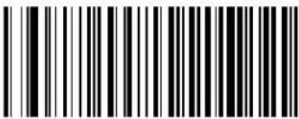 Country Mode = Spain Country Mode = Spain |

ENTER/EXIT PROGRAMMING MODE Caps Lock State
Country Mode (continued)
 Country Mode = Sweden Country Mode = Sweden | |
 Country Mode = Switzerland Country Mode = Switzerland | Supports only the interfaces listed in the Country Mode feature description. |
Caps Lock State
This option specifies the format in which the reader sends character data. This applies to keyboard wedge interfaces and Bluetooth HID Profile. This does not apply when an alternate key encoding keyboard is selected.



Caps Lock State = Caps Lock ON
Caps Lock State = AUTO Caps Lock Enable
Numlock
This option specifies the setting of the Numbers Lock (Numlock) key while in keyboard wedge interface. This only applies to alternate key encoding interfaces. It does not apply to USB keyboard.


Send Control Characters
This feature Specifies how the reader transmits ASCII control characters to the host. Reference Appendix E, Scancode Tables for more information about control characters.
Options are as follows:
Control Character 00. Characters from 00 to 0x1F are sent as control character Ctrl+Keys, special keys are located from 0x80 to 0xA1.
Control Character 01. Characters from 00 to 0x1F are sent as control character Ctrl+Capital Key, special keys are located from 0x80 to 0xA1.
Control Character 02. Special keys are located from 00 to 0x1F and characters from 0x80 to 0xFE are intended as an extended ASCII table (Microsoft Windows Codepage 1252 — see "Microsoft Windows Codepage 1252" on page 291).


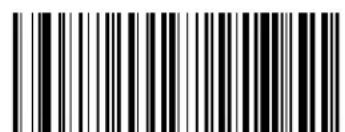
Wedge Send Control Characters = 01
Wedge Send Control Characters = 00

Wedge Send Control Characters = 02
Wedge Quiet Interval
This option specifies the amount of time to look for keyboard activity before the reader breaks the keyboard connection in order to transmit data to host. The selectable range for this feature is from 0 to 990ms in 10ms increments.

This feature applies ONLY to the Keyboard Wedge interface.
See page 239 in “References” for detailed information and examples for setting this feature.

Select Wedge Quiet Interval Setting
Make a mistake? Scan the CANCEL barcode to abort and not save the entry string. You can then start again at the beginning.
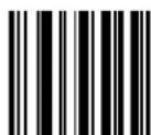
CANCEL
DEFAULT
10 = Quiet Interval of 100 ms

ENTER/EXIT PROGRAMMING MODE Intercharacter Delay
Intercharacter Delay
This parameter specifies the intercharacter delay between the end of one character and the beginning of the next. The delay can be set within a range of zero (0) to 990 milliseconds in 10ms increments. A setting of zero specifies no delay.

This feature applies ONLY to the Keyboard Wedge interface and Bluetooth HID Profile.
See page 240 in “References” for detailed information and examples for setting this feature.
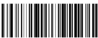 Intercharacter Delay = No Delay Intercharacter Delay = No Delay | |
 Select Intercharacter Delay Setting Select Intercharacter Delay Setting | |
| Make a mistake? Scan the CANCEL barcode to abort and not save the entry string. You can then start again at the beginning. |  CANCEL CANCEL |
DEFAULT
00 = No Intercharacter Delay
Intercode Delay
Specifies the delay between labels transmitted to the host for this interface. The selectable range for this feature is from 0 to 99 seconds.
See page 241 in “References” for detailed information and examples for setting this feature.
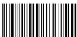
Set Intercode Delay
Make a mistake? Scan the CANCEL barcode to abort and not save the entry string. You can then start again at the beginning.
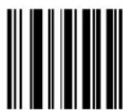
CANCEL
DEFAULT
00 = No Wedge Intercode Delay

ENTER/EXIT PROGRAMMING MODE USB Keyboard Speed
USB Keyboard Speed
This option specifies the USB poll rate for a USB keyboard.

This feature applies ONLY to the USB Keyboard interface.
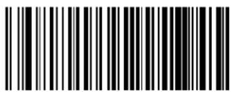

USB Keyboard Speed = 1ms


USB Keyboard Speed = 3ms
USB Keyboard Speed = 4ms

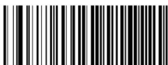
USB Keyboard Speed = 5ms
USB Keyboard Speed = 6ms

ENTER/EXIT PROGRAMMING MODE
USB Keyboard Speed (continued)
 USB Keyboard Speed = 7ms USB Keyboard Speed = 7ms | |
 USB Keyboard Speed = 8ms USB Keyboard Speed = 8ms | |
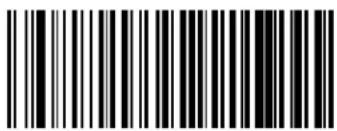 USB Keyboard Speed = 9ms USB Keyboard Speed = 9ms | |
 USB Keyboard Speed = 10ms USB Keyboard Speed = 10ms |
USB Keyboard Numeric Keypad
This option Controls whether numeric characters will be sent using standard keys or the numeric keypad.
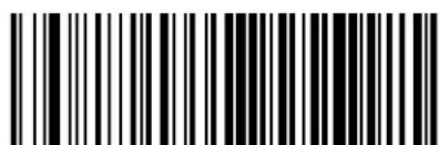

Standard Keys
USB-OEM INTERFACE
USB-OEM DEVICE USAGE on page 46
INTERFACE OPTIONS on page 46
Feature settings for USB interfaces differ depending upon which host type the reader will be connected with. Use the feature settings in this chapter to specifically configure for the USB-OEM interface. Other USB interfaces are included in the appropriate chapter for their host type.
Reference Appendix B, Standard Defaults for a listing of standard factory settings.
USB-OEM Device Usage
The USB-OEM protocol allows for the reader to be identified as one of two different types of barcode scanners. Depending on what other scanners you may already have connected to a USB-OEM POS, you may need to change this setting to enable all devices to communicate.
Options are:
- Table Top Scanner
- Handheld Scanner

It may be necessary to switch device usage when connecting two readers/scanners of the same type to a POS system.
 USB-OEM Device Usage = Table Top Scanner USB-OEM Device Usage = Table Top Scanner | |
 USB-OEM Device Usage = Handheld Scanner USB-OEM Device Usage = Handheld Scanner |  |
Interface Options
This feature provides for an interface-specific control mechanism.
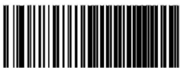 Obey Scanner Configuration Host Commands Obey Scanner Configuration Host Commands | |
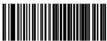 Ignore Scanner Configuration Host Commands Ignore Scanner Configuration Host Commands |  |
WAND EMULATION INTERFACE
| WAND SIGNAL SPEED on page 48 |
| WAND POLARITY on page 48 |
| WAND IDLE STATE on page 49 |
| TRANSMIT NOISE on page 49 |
| LABEL SYMBOLOGY CONVERSION on page 50 |
This chapter provides feature/settings configuration for the Wand Emulation interface. Reference Appendix B, Standard Defaults for a listing of standard factory settings.
Wand Signal Speed
This feature specifies the speed of the Wand output signal per nominal bar or space. Choices are:
• 330 microseconds
- 660 microseconds
 Wand Signal Speed = 330ms Wand Signal Speed = 330ms | |
 Wand Signal Speed = 660ms Wand Signal Speed = 660ms |  |
Wand Polarity
This option specifies the polarity of the Wand output signal. Choices are:
- Quiet zones and spaces are high, bars are low
- Quiet zones and spaces are low, bars are high

TTL logic levels:
0V <= Low <= 0.7V
2.4V <= High <= 5.25V
 Wand Polarity = Quiet Zones & Spaces High, Bars Low Wand Polarity = Quiet Zones & Spaces High, Bars Low | |
 Wand Polarity = Quiet Zones & Spaces Low, Bars High Wand Polarity = Quiet Zones & Spaces Low, Bars High |  |
ENTER/EXIT PROGRAMMING MODE Wand Idle State
Wand Idle State
This feature specifies the level of the Wand output signal when the reader is idle.

TTL logic levels:
0V <= Low <= 0.7V
2.4V <= High <= 5.25V
 Wand Idle State = Low Wand Idle State = Low | |
 Wand Idle State = High Wand Idle State = High |  |
Transmit Noise
This option specifies the leading/trailing noise for the Wand interface.
 | 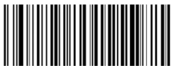 Transmit Noise = Disable Transmit Noise = Disable |
 Transmit Noise = Transmit leading noise Transmit Noise = Transmit leading noise | |
 Transmit Noise = Transmit trailing noise Transmit Noise = Transmit trailing noise | |
 Transmit Noise = Transmit leading and trailing noise Transmit Noise = Transmit leading and trailing noise |
Label Symbology Conversion
When this feature is enabled for the Wand Emulation interface, all barcode labels are converted to a single symbology.
Options are:
- No conversion
- Convert to Code 39 symbology
- Convert to Code 39 Full ASCII
- Convert to Code 128 symbology

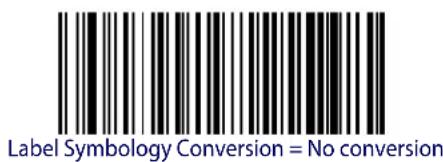

Label Symbology Conversion = Convert to Code 39

Label Symbology Conversion =

Convert to Code 39 Full ASCII
DATA FORMAT
| GLOBAL PREFIX/SUFFIX on page 52 |
| GLOBAL AIM ID on page 53 |
| GS1-128 AIM ID on page 54 |
| LABEL ID starting on page 55Label ID: Pre-loaded SetsLabel ID: Set Individually Per SymbologyLabel ID ControlLabel ID Symbology SelectionSet Global Mid Label ID Characters |
| CASE CONVERSION on page 64 |
| CHARACTER CONVERSION on page 64 |
The features in this chapter can be used to build specific user-defined data into a message string. See “References” starting on page 244 for more detailed instructions on setting these features.
Global Prefix/Suffix
This option sets up to 20 characters each from the set of ASCII characters or any hex value from 00 to FF. The characters may be added as a prefix (in a position before the barcode data, also called a header) and/or as a suffix (in a position following the barcode data, also called a footer). See page 245 for more detailed instructions on setting this feature.
To configure this feature, scan the ENTER/EXIT PROGRAMMING MODE barcode above to place the unit in Programming Mode, then the "Set Global Prefix" or "Set Global Suffix," barcode followed by the digits (in hex) from the Alphanumeric characters in Appendix D, Keypad representing your desired character(s). If less than the expected string of 20 characters are selected, scan the ENTER/EXIT barcode to terminate the string. Exit programming mode by scanning the ENTER/EXIT barcode again.
| Set Global Prefix | |
 Set Global Suffix Set Global Suffix | |
| Make a mistake? Scan the CANCEL barcode to abort and not save the entry string. You can then start again at the beginning. |  CANCEL CANCEL |

No Global Prefix Global Suffix = 0x0D (CR)
Global AIM ID

This feature enables/disables addition of AIM IDs for all symbology types.
AIM label identifiers (as opposed to custom characters you select yourself as with label identifiers) can be included with scanned barcode data. AIM label identifiers consist of three characters as follows:
- A close brace character (ASCII ']), followed by...
- A code character (see the table below), followed by...
- A modifier character (the modifier character is symbol dependent).
| SYMBOLOGY CHAR | SYMBOLOGY CHAR | ||
| UPC/EAN | E^a | Code 128/GS1-128 C | |
| Code 39 and Code 32 | A | DataBar Omnidirectional, DataBar Expanded | e |
| Codabar F Standard 2 of 5 S | |||
| Interleaved 2 of 5 I ISBN | X^b | ||
| Code 93 | G | Code 11 | H |
a. UPC-A and UPC-E labels are converted to EAN 13 when adding AIM IDs.
b. ISBN (X with a 0 modifier character)


Global AIM ID = Enable
Global AIM ID = Disable
GS1-128 AIM ID
If Global AIM ID is disabled, the AIM ID for GS1-128 can be enabled/disabled independently. The AIM ID for GS1-128 is a ]C1, ]C2 or ]C3.
AIM IDs for other symbologies can be enabled/disabled independently as well. Contact Customer Support for assistance

GS1-128 AIM ID = Enable

GS1-128 AIM ID = Disable

Label ID
A Label ID is a customizable code of up to three ASCII characters (each can be one of hex 0x01-0xFF), used to identify a barcode (symbology) type. It can be appended previous to or following the transmitted barcode data depending upon how this option is enabled. This feature provides options for configuring custom Label IDs as a pre-loaded set (see "Label ID: Pre-loaded Sets" below) or individually per symbology (see "Label ID: Set Individually Per Symbology" on page 55). If you wish to program the reader to always include an industry standard label identifier for ALL symbology types, see the previous feature "Global AIM ID" on page 53.
See Label ID, starting on page 247 of "References" for more information on setting this feature.
Label ID: Pre-loaded Sets
The reader supports two pre-loaded sets of Label IDs. See Label ID: Pre-loaded Sets, starting on page 247 for details on the USA set and the EU set.

CAUTION
When changing from one Label ID set to another, all other reader configuration settings, including the host interface type, will be erased and set to the standard factory defaults. Any custom configuration or custom defaults will be lost.


Label ID Pre-loaded Set = USA Set

Label ID: Set Individually Per Symbology
This feature configures a Label ID individually for a single symbology. See Label ID: Set Individually Per Symbology, starting on page 249 for detailed instructions on setting this feature.
Label ID Control
This option controls whether a Label ID is disabled, or sent as a prefix or suffix for a given symbology type.
 |  Label ID Transmission = Disable Label ID Transmission = Disable |
 Label ID Transmission = Enable as Prefix Label ID Transmission = Enable as Prefix | |
 Label ID Transmission = Enable as Suffix Label ID Transmission = Enable as Suffix | |
 CANCEL CANCEL | Make a mistake? Scan the CANCEL barcode to abort and not save the entry string. You can then start again at the beginning. |

ENTER/EXIT PROGRAMMING MODE Label ID Symbology Selection
Label ID Symbology Selection
This option selects the symbology for which a Label ID is to be configured. See "Label ID" on page 55 or page 249 in "References" for more detailed instructions.
 Set UPC-A Label ID Character(s) Set UPC-A Label ID Character(s) | |
 Set UPC-A/P2 Label ID Character(s) Set UPC-A/P2 Label ID Character(s) | |
 Set UPC-A/P5 Label ID Character(s) Set UPC-A/P5 Label ID Character(s) | |
 Set UPC-A/GS1-128 Label ID Character(s) Set UPC-A/GS1-128 Label ID Character(s) | |
 Set UPC-E Label ID Character(s) Set UPC-E Label ID Character(s) | |
 Set UPC-E/P2 Label ID Character(s) Set UPC-E/P2 Label ID Character(s) | |
 Set UPC-E/P5 Label ID Character(s) Set UPC-E/P5 Label ID Character(s) |

ENTER/EXIT PROGRAMMING MODE
Label ID Symbology Selection (continued)
 Set UPC-E/GS1-128 Label ID Character(s) Set UPC-E/GS1-128 Label ID Character(s) | |
 Set EAN 13 Label ID Character(s) Set EAN 13 Label ID Character(s) | |
 Set EAN 13/P2 Label ID Character(s) Set EAN 13/P2 Label ID Character(s) | |
 Set EAN 13/P5 Label ID Character(s) Set EAN 13/P5 Label ID Character(s) | |
 Set EAN 13/GS1-128 Label ID Character(s) Set EAN 13/GS1-128 Label ID Character(s) | |
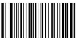 Set EAN 8 Label ID Character(s) Set EAN 8 Label ID Character(s) | |
 Set EAN 8/P2 Label ID Character(s) Set EAN 8/P2 Label ID Character(s) |

ENTER/EXIT PROGRAMMING MODE Label ID Symbology Selection
Label ID Symbology Selection (continued)
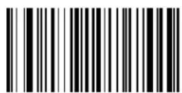 Set EAN 8/P5 Label ID Character(s) Set EAN 8/P5 Label ID Character(s) | |
| Set EAN 8/GS1-128 Label ID Character(s) | |
 Set GTIN Label ID Character(s) Set GTIN Label ID Character(s) | |
| Set GTIN/P2 Label ID Character(s) | |
 Set GTIN/P5 Label ID Character(s) Set GTIN/P5 Label ID Character(s) | |
| Set GTIN/GS1-128 Label ID Character(s) | |
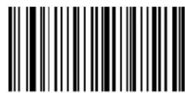 Set Code 39 Label ID Character(s) Set Code 39 Label ID Character(s) |

ENTER/EXIT PROGRAMMING MODE
Label ID Symbology Selection (continued)
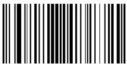 Set Code 32 Label ID Character(s) Set Code 32 Label ID Character(s) | |
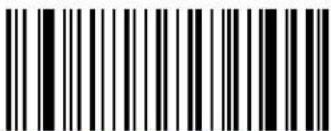 Set Code 39 CIP Label ID Character(s) Set Code 39 CIP Label ID Character(s) | |
 Set Code 128 Label ID Character(s) Set Code 128 Label ID Character(s) | |
 Set GS1-128 Label ID Character(s) Set GS1-128 Label ID Character(s) | |
 Set ISBT 128 Label ID Character(s) Set ISBT 128 Label ID Character(s) | |
 Set Codablock F Label ID Character(s) Set Codablock F Label ID Character(s) | |
 Set Interleaved 2 of 5 Label ID Character(s) Set Interleaved 2 of 5 Label ID Character(s) | |
 Set Follett 2 of 5 Label ID Character(s) Set Follett 2 of 5 Label ID Character(s) |

ENTER/EXIT PROGRAMMING MODE Label ID Symbology Selection
Label ID Symbology Selection (continued)
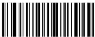 Set Interleaved 2 of 5 CIP HR Label ID Character(s)
 | |
 Set Standard 2 of 5 Label ID Character(s)
 | |
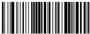 Set Industrial 2 of 5 Label ID Character(s)
 | |
 Set IATA Label ID Character(s)
 | |
 Set China Postal Code Label ID Character(s)
 | |
 Set Codabar Label ID Character(s)
 | |
 Set ABC Codabar Label ID Character(s)
 |
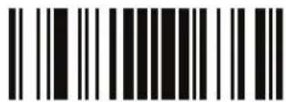
ENTER/EXIT PROGRAMMING MODE
Label ID Symbology Selection (continued)
 Set Code 11 Label ID Character(s) Set Code 11 Label ID Character(s) | |
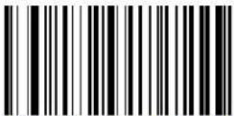 Set DataBar Omnidirectional Label ID Character(s) Set DataBar Omnidirectional Label ID Character(s) | |
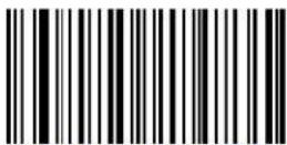 Set DataBar Expanded Label ID Character(s) Set DataBar Expanded Label ID Character(s) | |
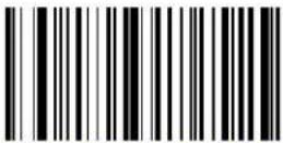 Set DataBar Limited Label ID Character(s) Set DataBar Limited Label ID Character(s) | |
 Set Code 93 Label ID Character(s) Set Code 93 Label ID Character(s) | |
 Set MSI Label ID Character(s) Set MSI Label ID Character(s) | |
 Set Plessey Label ID Character(s) Set Plessey Label ID Character(s) | |

ENTER/EXIT PROGRAMMING MODE Set Global Mid Label ID Characters
Label ID Symbology Selection (continued)

Set Anker Plessey Label ID Character(s)

Set Code 4 Label ID Character(s)

Set Code 5 Label ID Character(s)
Set Global Mid Label ID Characters
Specifies mid-label ID that is added for transmission between the labels of a two-label pair.
To configure this feature, scan the ENTER/EXIT PROGRAMMING MODE barcode above to place the unit in Programming Mode, then the "Set Global Mid Label ID Character(s)" barcode followed by the digits (in hex) from the Alphanumeric characters in Appendix D, Keypad representing your desired character(s). If less than the expected string of 20 characters are selected, scan the ENTER/EXIT barcode to terminate the string. Exit programming mode by scanning the ENTER/EXIT barcode again.

Set Global Mid Label ID Character(s)
Make a mistake? Scan the CANCEL barcode to abort and not save the entry string. You can then start again at the beginning.

CANCEL

No Mid Label ID
Character (00)
Case Conversion
This feature allows conversion of the case of all alphabetic characters to upper or lower case.

Case conversion affects ONLY scanned barcode data, and does not affect Label ID, Prefix, Suffix, or other appended data.


Character Conversion
Character conversion is an eight byte configuration item. The eight bytes are 4 character pairs represented in hexadecimal ASCII values. The first character in the pair is the character that will be converted. The second character in the pair is the character to convert to. If the character to convert in a pair is FF, then no conversion is done.

If less than the expected string of 16 characters are selected, scan the ENTER/EXIT barcode twice to accept the selections and exit Programming Mode.


0xFFFFFFFFFFFFFFFF (No character conversion)
READING PARAMETERS
| DOUBLE READ TIMEOUT on page 66 | GOOD READ BEEP VOLUME on page 71 |
| LABEL GONE TIMEOUT on page 67 | GOOD READ LED DURATION on page 72 |
| POWER ON ALERT on page 68 | SCAN MODE on page 73 |
| GOOD READ: WHEN TO INDICATE on page 68 | SCANNING ACTIVE TIME on page 74 |
| GOOD READ BEEP TYPE on page 69 | FLASH ON TIME on page 74 |
| GOOD READ BEEP FREQUENCY on page 69 | FLASH OFF TIME on page 75 |
| GOOD READ BEEP LENGTH on page 70 | GREEN SPOT DURATION on page 75 |
Double Read Timeout
Double Read Timeout prevents a double read of the same label by setting the minimum time allowed between reads of labels of the same symbology and data. If the unit reads a label and sees the same label again within the specified timeout, the second read is ignored. Double Read Timeout does not apply to scan modes that require a trigger pull for each label read.
 Double Read Timeout = 0.1 Second Double Read Timeout = 0.1 Second | |
 Double Read Timeout = 0.2 Second Double Read Timeout = 0.2 Second | |
 Double Read Timeout = 0.3 Second Double Read Timeout = 0.3 Second | |
 Double Read Timeout = 0.4 Second Double Read Timeout = 0.4 Second | |
 Double Read Timeout = 0.5 Second Double Read Timeout = 0.5 Second | |
 Double Read Timeout = 0.6 Second Double Read Timeout = 0.6 Second |  |
 Double Read Timeout = 0.7 Second Double Read Timeout = 0.7 Second |
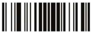
ENTER/EXIT PROGRAMMING MODE Label Gone Timeout
Double Read Timeout (continued)

Double Read Timeout = 0.8 Second

Double Read Timeout = 0.9 Second

Double Read Timeout = 1 Second
Label Gone Timeout
This feature sets the time after the last label segment is seen before the reader prepares for a new label. The timeout can be set within a range of 10 milliseconds to 2,550 milliseconds (2.55 seconds) in 10ms increments. Label Gone Timeout does not apply to scan modes that require a trigger pull for each label that is read. See page 252 in “References” for detailed instructions and examples for setting this feature.

Select Label Gone Timeout Setting
Make a mistake? Scan the CANCEL barcode to abort and not save the entry string. You can then start again at the beginning.

CANCEL
DEFAULT
016 = Timeout of 160 ms
LED AND BEEPER INDICATORS
Power On Alert
Disables or enables the indication (from the Beeper) that the reader is receiving power.
 Power On Alert = Disable (No Audible Indication) Power On Alert = Disable (No Audible Indication) | |
 Power On Alert = Four Beeps Power On Alert = Four Beeps |  |
Good Read: When to Indicate
This feature specifies when the reader will provide indication (beep and/or flash its green LED) upon successfully reading a barcode.

This option, which uses CTS, is only valid for RS-232 interfaces.
 |  Indicate Good Read = After Decode Indicate Good Read = After Decode |
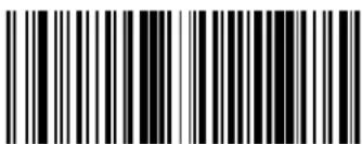 Indicate Good Read = After Transmit Indicate Good Read = After Transmit | |
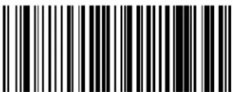 Indicate Good Read = After CTS Goes Inactive, Then Active Indicate Good Read = After CTS Goes Inactive, Then Active |

ENTER/EXIT PROGRAMMING MODE Good Read Beep Type
Good Read Beep Type
Specifies whether the good read beep has a mono or bitonal beep sound.


Good Read Beep Type = Bitonal
Good Read Beep Frequency
Adjusts the good read beep to sound at a selectable low, medium or high frequency, selectable from the list below. (Controls the beeper's pitch/tone.)
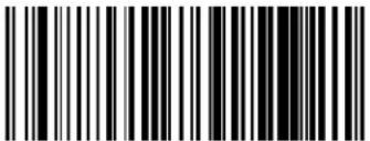 Good Read Beep Frequency = Low Good Read Beep Frequency = Low | |
 Good Read Beep Frequency = Medium Good Read Beep Frequency = Medium | |
| DEFAULT |  Good Read Beep Frequency = High Good Read Beep Frequency = High |

LED and Beeper Indicators ENTER/EXIT PROGRAMMING MODE
Good Read Beep Length
 Good Read Beep Length = 60 msec Good Read Beep Length = 60 msec | |
 Good Read Beep Length = 80 msec Good Read Beep Length = 80 msec |  |
 Good Read Beep Length = 100 msec Good Read Beep Length = 100 msec | |
 Good Read Beep Length = 120 msec Good Read Beep Length = 120 msec | |
 Good Read Beep Length = 140 msec Good Read Beep Length = 140 msec | |
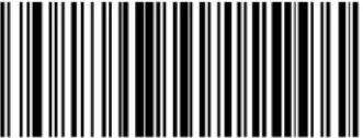 Good Read Beep Length = 160 msec Good Read Beep Length = 160 msec | |
 Good Read Beep Length = 180 msec Good Read Beep Length = 180 msec | |
 Good Read Beep Length = 200 msec Good Read Beep Length = 200 msec |

ENTER/EXIT PROGRAMMING MODE Good Read Beep Volume
Good Read Beep Volume
Selects the beeper volume (loudness) upon a good read beep. There are three selectable volume levels.
 Good Read Beep Volume = Beeper Off Good Read Beep Volume = Beeper Off | |
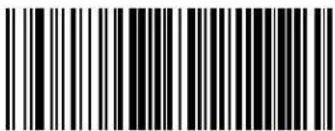 Good Read Beep Volume = Low Good Read Beep Volume = Low | |
 Good Read Beep Volume = Medium Good Read Beep Volume = Medium | |
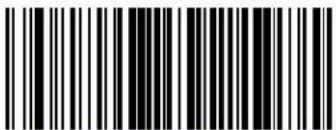 Good Read Beep Volume = High Good Read Beep Volume = High |  |
Good Read LED Duration
This feature specifies the amount of time that the Good Read LED remains on following a good read. The good read LED on time can be set within a range of 10 milliseconds to 2,550 milliseconds (0.001 to 2.55 seconds) in 100ms increments.
See page 253 in “References” for detailed instructions and examples for setting this feature.

Select Good Read LED Duration Setting
Make a mistake? Scan the CANCEL barcode to abort and not save the entry string. You can then start again at the beginning.

CANCEL
DEFAULT
003 = Good Read LED stays on for 300 ms

Indicators are dimmed during sleep.

ENTER/EXIT PROGRAMMING MODE Scan Mode
SCANNING FEATURES
Scan Mode
Selects the reader's scan operating mode. See page 254 in "References" for descriptions.
 Scan Mode = Trigger Single Scan Mode = Trigger Single |  |
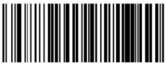 Scan Mode = Trigger Hold Multiple Scan Mode = Trigger Hold Multiple | |
 Scan Mode = Trigger Pulse Multiple Scan Mode = Trigger Pulse Multiple | |
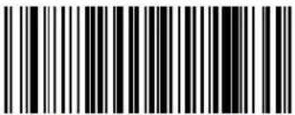 Scan Mode = Flashinga Scan Mode = Flashinga | |
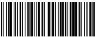 Scan Mode = Always Onb Scan Mode = Always Onb |
a. Recommended scan mode for hands-free stand mode operation.
b. See "Laser Features" starting on page 227 for additional laser programmable timeout options.
Scanning Active Time
This setting specifies the amount of time that the reader stays in scan ON state once the state is entered. The range for this setting is from 1 to 255 seconds in 1-second increments. See page 255 in “References” for descriptions of each feature

Make a mistake? Scan the CANCEL barcode to abort and not save the entry string. You can then start again at the beginning.

DEFAULT
005 = Scanning is active for 5 Seconds
Flash On Time
This feature specifies the ON time for the indicator LED while in Flash Mode. The selectable range is 100 to 9,900 milliseconds (0.1 to 9.9 seconds), in 100 millisecond increments. See page 256 in “References” for detailed information on setting this feature.
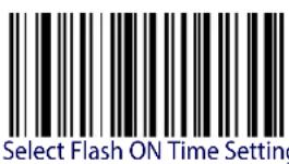
Make a mistake? Scan the CANCEL barcode to abort and not save the entry string. You can then start again at the beginning.
DEFAULT
10 = Flash is ON for 1 Second

ENTER/EXIT PROGRAMMING MODE Flash Off Time
Flash Off Time
This feature specifies the OFF time for the indicator LED while in Flash Mode. The selectable range is 100 to 9,900 milliseconds (0.1 to 9.9 seconds), in 100 millisecond increments. See page 257 in "References" for detailed information on setting this feature.

Select Flash OFF Time Setting
Make a mistake? Scan the CANCEL barcode to abort and not save the entry string. You can then start again at the beginning.

CANCEL
DEFAULT
06 = Flash is OFF for 600ms
Green Spot Duration
Specifies the duration of the good read pointer beam after a good read.
 Green Spot Duration = Disable (Green Spot is Off) Green Spot Duration = Disable (Green Spot is Off) | |
 Green Spot Duration = Short (300 msec) Green Spot Duration = Short (300 msec) |  |
 Green Spot Duration = Medium (500 msec) Green Spot Duration = Medium (500 msec) | |
 Green Spot Duration = Long (800 msec) Green Spot Duration = Long (800 msec) |
NOTES
CODE SELECTION
The reader supports the following symbologies (barcode types). Symbology-dependent options for each symbology are included in this chapter.
| CODE EAN/UPC on page 79 | STANDARD 2 OF 5 on page 148 |
| • Coupon Control | INDUSTRIAL 2 OF 5 on page 154 |
| • UPC-A • Code IATA | |
| • UPC-E | CHINA POSTAL CODE on page 161 |
| • EAN 13 (Jan 13) | CODABAR on page 167 |
| • ISSN • ABC Codabar | |
| • EAN 8 (Jan 8) | CODE 11 on page 182 |
| • UPC/EAN Global Settings | GS1 DATABARTM OMNIDIRECTIONAL on page 191 |
| CODE 39 on page 106 | • GS1 DataBarTM Omnidirectional |
| • Code 32 (ITAL Pharmaceutical Code) | • GS1 DataBarTM Expanded |
| • Code 39 CIP (French Pharmaceutical) | • GS1 DataBarTM Limited |
| CODE 128 on page 121 | CODE 93 on page 199 |
| • GS1-128 | MSI on page 207 |
| CODE ISBT 128 on page 132 | PLESSEY on page 213 |
| CODABLOCK F on page 135 | CODE 4 on page 221 |
| INTERLEAVED 2 OF 5 (I 2 OF 5) on page 139 | CODE 5 on page 222 |
| • Follett 2 of 5 | |
| • Interleaved 2 of 5 CIP HR |
Default settings are indicated at each feature/option with a green arrow. Also reference Appendix B, Standard Defaults for a listing of the most widely used set of standard factory settings. That section also provides space to record any custom settings needed or implemented for your system.
To set most features:
- Scan the ENTER/EXIT PROGRAMMING barcode at the top of a applicable programming pages.
-
Scan the correct barcode to set the desired programming feature or parameter. You may need to cover unused barcodes on the page, and possibly the facing page, to ensure that the reader reads only the barcode you intend to scan.
-
If additional input parameters are needed, go to Appendix D, Keypad, and scan the appropriate characters from the keypad.

Additional information about many features can be found in the "References" chapter.
If you make a mistake before the last character, scan the CANCEL barcode to abort and not save the entry string. You can then start again at the beginning.
- Complete the programming sequence by scanning the ENTER/EXIT PROGRAMMING barcode to exit Programming Mode.
DISABLE ALL SYMBOLOGIES
Use this feature to disable all symbologies.
- Scan the ENTER/EXIT PROGRAMMING barcode below.
- Scan the Disable All Symbologies barcode.
- Complete the programming sequence by scanning the ENTER/EXIT PROGRAMMING barcode.


This does not disable the reading of programming labels.
ENTER/EXIT PROGRAMMING MODE Coupon Control
CODE EAN/UPC
Coupon Control
This feature is used to control the reader's method of processing coupon labels.
 Coupon Control = Allow all coupon barcodes to be decoded Coupon Control = Allow all coupon barcodes to be decoded | |
 Coupon Control = Enable only UPCA coupon decoding Coupon Control = Enable only UPCA coupon decoding |  |
 Coupon Control = Enable only GS1 DataBar ^TM coupon decoding Coupon Control = Enable only GS1 DataBar ^TM coupon decoding |
UPC-A
The following options apply to the UPC-A symbology.
UPC-A Enable/Disable
When disabled, the reader will not read UPC-A barcodes.
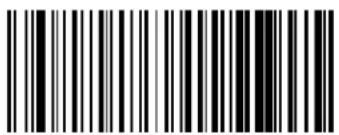 UPC-A = Disable UPC-A = Disable | |
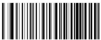 UPC-A = Enable UPC-A = Enable |  |
UPC-A Check Character Transmission
Enable this option to transmit the check character along with UPC-A barcode data.
 UPC-A Check Character Transmission = Don’t Send UPC-A Check Character Transmission = Don’t Send | |
 |  |

ENTER/EXIT PROGRAMMING MODE Expand UPC-A to EAN-13
Expand UPC-A to EAN-13
Expands UPC-A data to the EAN-13 data format. Selecting this feature also changes the symbology ID to match those required for EAN-13.


UPC-A to EAN-13 = Don't Expand
UPC-A to EAN-13 = Expand
UPC-A Number System Character Transmission
This feature enables/disables transmission of the UPC-A number system character.
 UPC-A Number System Character = Do not transmit UPC-A Number System Character = Do not transmit | |
 UPC-A Number System Character = Transmit UPC-A Number System Character = Transmit |  |
UPC-A Minimum Reads
This feature specifies the minimum number of consecutive times a UPC-A label must be decoded before it is accepted as a good read.
 |  UPC-A Minimum Reads = 1 UPC-A Minimum Reads = 1 |
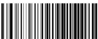 UPC-A Minimum Reads = 2 UPC-A Minimum Reads = 2 | |
 UPC-A Minimum Reads = 3 UPC-A Minimum Reads = 3 | |
 UPC-A Minimum Reads = 4 UPC-A Minimum Reads = 4 |

ENTER/EXIT PROGRAMMING MODE UPC-E Enable/Disable
UPC-E
The following options apply to the UPC-E symbology.
UPC-E Enable/Disable
When disabled, the reader will not read UPC-E barcodes.
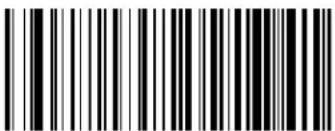
 UPC-E = Disable UPC-E = Disable | |
 UPC-E = Enable UPC-E = Enable |  |
UPC-E Check Character Transmission
Enable this option to transmit the check character along with UPC-E barcode data.
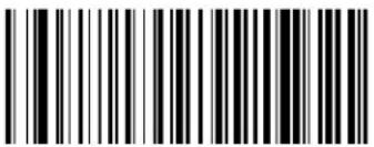
 UPC-E Check Character Transmission = Don’t Send UPC-E Check Character Transmission = Don’t Send | |
 UPC-E Check Character Transmission = Send UPC-E Check Character Transmission = Send |  |
Expand UPC-E to EAN-13
Expands UPC-E data to the EAN-13 data format. Selecting this feature also changes the symbology ID to match those required for EAN-13.



UPC-E to EAN-13 = Expand
UPC-E to EAN-13 = Don't Expand
Expand UPC-E to UPC-A
Expands UPC-E data to the UPC-A data format.


UPC-E to UPC-A = Don't Expand

UPC-E to UPC-A = Expand

ENTER/EXIT PROGRAMMING MODE UPC-E Number System Character Transmission
UPC-E Number System Character Transmission
This feature enables/disables transmission of the UPC-E system number character.
 UPC-E Number System Character = Do not transmit UPC-E Number System Character = Do not transmit | |
 UPC-E Number System Character = Transmit UPC-E Number System Character = Transmit |  |
UPC-E Minimum Reads
Specifies the minimum number of consecutive times a UPC-E label must be decoded before it is accepted as a good read.
 UPC-E Minimum Reads = 1 UPC-E Minimum Reads = 1 | |
 UPC-E Minimum Reads = 2 UPC-E Minimum Reads = 2 |  |
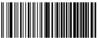 UPC-E Minimum Reads = 3 UPC-E Minimum Reads = 3 | |
 UPC-E Minimum Reads = 4 UPC-E Minimum Reads = 4 |
GTIN FORMATTING
This feature enables/disables the ability to convert UPC-E, UPC-A, EAN 8, and EAN 13 labels into the GTIN 14-character format.

If add-on information is present on the base label prior to the conversion taking place, the add-on information will be appended to the converted GTIN label.


ENTER/EXIT PROGRAMMING MODE EAN 13 Enable/Disable
EAN 13 (JAN 13)
The following options apply to the EAN 13 (Jan 13) symbology.
EAN 13 Enable/Disable
When disabled, the reader will not read EAN 13/JAN 13 barcodes.
 EAN 13 = Disable EAN 13 = Disable | |
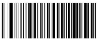 EAN 13 = Enable EAN 13 = Enable |  |
EAN 13 Check Character Transmission
Enable this option to transmit the check character along with EAN 13 barcode data.
 EAN 13 Check Character Transmission = Don’t Send EAN 13 Check Character Transmission = Don’t Send | |
 EAN 13 Check Character Transmission = Send EAN 13 Check Character Transmission = Send |  |
EAN-13 Flag 1 Character
Enables/disables transmission of an EAN/JAN13 Flag1 character. The Flag 1 character is the first character of the label.
 EAN-13 Flag 1 Char= Don’t transmit EAN-13 Flag 1 Char= Don’t transmit | |
 EAN-13 Flag 1 Char= Transmit EAN-13 Flag 1 Char= Transmit |  |
EAN-13 ISBN Conversion
This option enables/disables conversion of EAN 13/JAN 13 Bookland labels starting with 978 to ISBN labels.
 |  EAN-13 ISBN Conversion = Disable EAN-13 ISBN Conversion = Disable |
 EAN-13 ISBN Conversion = Convert to ISBN EAN-13 ISBN Conversion = Convert to ISBN |

ENTER/EXIT PROGRAMMING MODE EAN 13 Minimum Reads
EAN 13 Minimum Reads
This feature specifies the minimum number of consecutive times an EAN 13 label must be decoded before it is accepted as good read.
 |  EAN 13 Minimum Reads = 1 EAN 13 Minimum Reads = 1 |
 EAN 13 Minimum Reads = 2 EAN 13 Minimum Reads = 2 | |
 EAN 13 Minimum Reads = 3 EAN 13 Minimum Reads = 3 | |
 EAN 13 Minimum Reads = 4 EAN 13 Minimum Reads = 4 |
ISSN
The following options apply to the ISSN symbology.
ISSN Enable/Disable
Enables/disables conversion of EAN/JAN13 Bookland labels starting with 977 to ISSN labels.


ENTER/EXIT PROGRAMMING MODE EAN 8 Enable/Disable
EAN 8 (JAN 8)
The following options apply to the EAN 8 (Jan 8) symbology.
EAN 8 Enable/Disable
When disabled, the reader will not read EAN 8/JAN 8 barcodes.
 EAN 8 = Disable EAN 8 = Disable | |
 EAN 8 = Enable EAN 8 = Enable |  |
EAN 8 Check Character Transmission
Enable this option to transmit the check character along with EAN 8 barcode data.
 EAN 8 Check Character Transmission = Don't Send EAN 8 Check Character Transmission = Don't Send | |
 EAN 8 Check Character Transmission = Send EAN 8 Check Character Transmission = Send |  |
Expand EAN 8 to EAN 13
Enable this option to expand EAN 8/JAN 8 labels to EAN 13/JAN 13.



Expand EAN 8 to EAN 13 = Disable
Expand EAN 8 to EAN 13 = Enable
EAN 8 Minimum Reads
This feature specifies the minimum number of consecutive times an EAN 8 (Jan 8) label must be decoded before it is accepted as good read.
DEFAULT

EAN 8 Minimum Reads = 1

EAN 8 Minimum Reads = 2

EAN 8 Minimum Reads = 3

EAN 8 Minimum Reads = 4
UPC/EAN GLOBAL SETTINGS
This section provides configuration settings for UPC-A, UPC-E, EAN 13 and EAN 8 symbologies, and affects all of these unless otherwise marked for each feature description.
UPC/EAN Decoding Level
Decoding Levels are used to configure a barcode symbology decoder to be very aggressive to very conservative depending on a particular customer's needs.
See page 242 for more information on this feature.
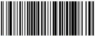 UPC/EAN Decoding Level = 1 (Conservative) UPC/EAN Decoding Level = 1 (Conservative) | |
 |  UPC/EAN Decoding Level = 2 UPC/EAN Decoding Level = 2 |
 UPC/EAN Decoding Level = 3 UPC/EAN Decoding Level = 3 | |
 UPC/EAN Decoding Level = 4 UPC/EAN Decoding Level = 4 | |
 UPC/EAN Decoding Level = 5 (Aggressive) UPC/EAN Decoding Level = 5 (Aggressive) |
UPC/EAN Correlation
When correlation is enabled, the reader will combine label data from multiple scans when decoding. This will help the scanner read labels that have spots, voids and/or damaged areas. Enabling correlation will also increase the chances that a label will be read incorrectly.


UPC/EAN Price Weight Check
This feature enables/disables calculation and verification of price/weight check digits.


Price Weight Check = 4-digit price-weight check

Price Weight Check = 5-digit price-weight check

Price Weight Check = European 4-digit price-weight check

Price Weight Check = European 5-digit price-weight check

ENTER/EXIT PROGRAMMING MODE In-Store Minimum Reads
In-Store Minimum Reads
This feature specifies the minimum number of consecutive times an in-store label must be decoded before it is accepted as good read.
In-store labels are defined as UPC-A labels with a number-system character of 2 or 4 as well as EAN 8 and EAN 13 labels with a Flag1 character of 2 or an EAN 13 label starting with the three characters '980'.
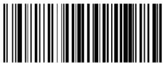 In-Store Minimum Reads = 1 In-Store Minimum Reads = 1 | |
 In-Store Minimum Reads = 2 In-Store Minimum Reads = 2 |  |
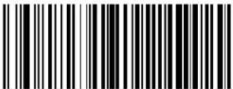 In-Store Minimum Reads = 3 In-Store Minimum Reads = 3 | |
 In-Store Minimum Reads = 4 In-Store Minimum Reads = 4 |
ADD-ONS
Contact Customer Support for advanced programming of optional and conditional add-ons.
Optional Add-ons
The reader can be enabled to optionally read the following add-ons (supplementals):

If a UPC/EAN base label and an add-on are both decoded, the reader will transmit the base label and add-on. If a UPC/EAN base label is decoded without an add-on, the base label will be transmitted without an add-on. Conditional add-on settings (if enabled) are considered by the reader before optional add-on settings.
 |  |
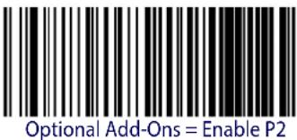 | |
 |  |
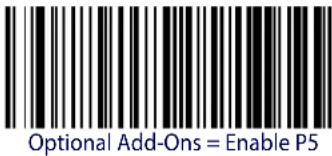 | |
 |  |
 |

ENTER/EXIT PROGRAMMING MODE Optional Add-On Timer
Optional Add-On Timer
This option sets the time the reader will look for an add-on when an add-on fragment has been seen and optional add-ons are enabled. (Also see "Optional GS1-128 Add-On Timer" on page 100.)
 Optional Add-on Timer = 10ms Optional Add-on Timer = 10ms | |
 Optional Add-on Timer = 20ms Optional Add-on Timer = 20ms | |
 Optional Add-on Timer = 30ms Optional Add-on Timer = 30ms | |
 Optional Add-on Timer = 40ms Optional Add-on Timer = 40ms | |
 Optional Add-on Timer = 50ms Optional Add-on Timer = 50ms |

Add-Ons ENTER/EXIT PROGRAMMING MODE
Optional Add-On Timer (continued)
 Optional Add-on Timer = 60ms Optional Add-on Timer = 60ms | |
 Optional Add-on Timer = 70ms Optional Add-on Timer = 70ms |  |
 Optional Add-on Timer = 100ms Optional Add-on Timer = 100ms | |
 Optional Add-on Timer = 120ms Optional Add-on Timer = 120ms | |
 Optional Add-on Timer = 140ms Optional Add-on Timer = 140ms | |
 Optional Add-on Timer = 160ms Optional Add-on Timer = 160ms |

ENTER/EXIT PROGRAMMING MODE Optional Add-On Timer
Optional Add-On Timer (continued)
 Optional Add-on Timer = 180ms Optional Add-on Timer = 180ms | |
| Optional Add-on Timer = 200ms | |
 Optional Add-on Timer = 220ms Optional Add-on Timer = 220ms | |
| Optional Add-on Timer = 240ms | |
 Optional Add-on Timer = 260ms Optional Add-on Timer = 260ms | |
| Optional Add-on Timer = 280ms | |
 Optional Add-on Timer = 300ms Optional Add-on Timer = 300ms |
Optional GS1-128 Add-On Timer
This option sets the timer expiration value to read the added part after reading the linear EAN/UPC part. For UPC/EAN add-ons other than those of that type, see "Optional Add-On Timer" on page 97.
 |  Optional GS1-128 Add-On Timer = Disable Optional GS1-128 Add-On Timer = Disable |
 Optional GS1-128 Add-On Timer = 10ms Optional GS1-128 Add-On Timer = 10ms | |
 Optional GS1-128 Add-On Timer = 20ms Optional GS1-128 Add-On Timer = 20ms | |
 Optional GS1-128 Add-On Timer = 30ms Optional GS1-128 Add-On Timer = 30ms | |
 Optional GS1-128 Add-On Timer = 40ms Optional GS1-128 Add-On Timer = 40ms | |
 Optional GS1-128 Add-On Timer = 50ms Optional GS1-128 Add-On Timer = 50ms |

ENTER/EXIT PROGRAMMING MODE Optional GS1-128 Add-On Timer
Optional GS1-128 Add-On Timer (continued)
 Optional GS1-128 Add-On Timer = 60ms Optional GS1-128 Add-On Timer = 60ms | |
 Optional GS1-128 Add-On Timer = 70ms Optional GS1-128 Add-On Timer = 70ms | |
 Optional GS1-128 Add-On Timer = 100ms Optional GS1-128 Add-On Timer = 100ms | |
 Optional GS1-128 Add-On Timer = 120ms Optional GS1-128 Add-On Timer = 120ms | |
 Optional GS1-128 Add-On Timer = 140ms Optional GS1-128 Add-On Timer = 140ms | |
 Optional GS1-128 Add-On Timer = 160ms Optional GS1-128 Add-On Timer = 160ms |

Add-Ons ENTER/EXIT PROGRAMMING MODE
Optional GS1-128 Add-On Timer (continued)
 Optional GS1-128 Add-On Timer = 180ms Optional GS1-128 Add-On Timer = 180ms | |
 Optional GS1-128 Add-On Timer = 200ms Optional GS1-128 Add-On Timer = 200ms | |
 Optional GS1-128 Add-On Timer = 220ms Optional GS1-128 Add-On Timer = 220ms | |
 Optional GS1-128 Add-On Timer = 240ms Optional GS1-128 Add-On Timer = 240ms | |
 Optional GS1-128 Add-On Timer = 260ms Optional GS1-128 Add-On Timer = 260ms | |
 Optional GS1-128 Add-On Timer = 280ms Optional GS1-128 Add-On Timer = 280ms | |
 Optional GS1-128 Add-On Timer = 300ms Optional GS1-128 Add-On Timer = 300ms |

ENTER/EXIT PROGRAMMING MODE P2 Add-Ons Minimum Reads
P2 Add-Ons Minimum Reads
This feature specifies the minimum number of times a P2 add-on must be read before it is marked as valid and then combined with a base label.
 P2 Add-Ons Minimum Reads = 1 P2 Add-Ons Minimum Reads = 1 | |
 P2 Add-Ons Minimum Reads = 2 P2 Add-Ons Minimum Reads = 2 |  |
 P2 Add-Ons Minimum Reads = 3 P2 Add-Ons Minimum Reads = 3 | |
 P2 Add-Ons Minimum Reads = 4 P2 Add-Ons Minimum Reads = 4 |
P5 Add-Ons Minimum Reads
This feature specifies the minimum number of times a P5 add-on must be read before it is marked as valid and then combined with a base label.
 |  P5 Add-Ons Minimum Reads = 1 P5 Add-Ons Minimum Reads = 1 |
 P5 Add-Ons Minimum Reads = 2 P5 Add-Ons Minimum Reads = 2 | |
 P5 Add-Ons Minimum Reads = 3 P5 Add-Ons Minimum Reads = 3 | |
 P5 Add-Ons Minimum Reads = 4 P5 Add-Ons Minimum Reads = 4 |

ENTER/EXIT PROGRAMMING MODE GS1-128 Add-Ons Minimum Reads
GS1-128 Add-Ons Minimum Reads
This feature specifies the minimum number of times an GS1-128 add-on must be read before it is marked as valid and then combined with a base label.
 |  GS1-128 Add-Ons Minimum Reads = 1 GS1-128 Add-Ons Minimum Reads = 1 |
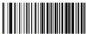 GS1-128 Add-Ons Minimum Reads = 2 GS1-128 Add-Ons Minimum Reads = 2 | |
 GS1-128 Add-Ons Minimum Reads = 3 GS1-128 Add-Ons Minimum Reads = 3 | |
 GS1-128 Add-Ons Minimum Reads = 4 GS1-128 Add-Ons Minimum Reads = 4 |
CODE 39
The following options apply to the Code 39 symbology.
Code 39 Enable/Disable
 Code 39 = Disable Code 39 = Disable | |
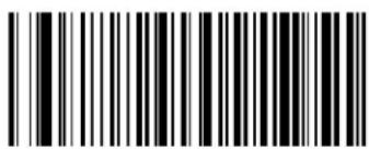 Code 39 = Enable Code 39 = Enable |  |
Code 39 Check Character Calculation
Enable this option to enables/disables calculation and verification of an optional Code 39 check character. When disabled, any check character in the label is treated as a data character
 |  Code 39 Check Character Calculation = Don’t Calculate Code 39 Check Character Calculation = Don’t Calculate |
 Code 39 Check Character Calculation = Calculate Std Check Code 39 Check Character Calculation = Calculate Std Check | |
 Code 39 Check Character Calculation = Calculate Mod 7 Check Code 39 Check Character Calculation = Calculate Mod 7 Check |
Code 39 Check Character Calculation (continued)

Code 39 Check Character Calculation = Enable Italian Post Check

Code 39 Check Character Calculation = Enable Daimler Chrysler Check
Code 39 Check Character Transmission
Enable this option to transmit the check character along with Code 39 barcode data.
| Code 39 Check Character Transmission = Don’t Send | |
 Code 39 Check Character Transmission = Send Code 39 Check Character Transmission = Send |  |
Code 39 Start/Stop Character Transmission
Enable this option to enable/disable transmission of Code 39 start and stop characters.


Code 39 Start/Stop Character Transmission = Don't Transmit
Code 39 Full ASCII
Enables/disables the translation of Code 39 characters to Code 39 full-ASCII characters.


Code 39 Full ASCII = Disable
Code 39 Full ASCII = Enable

ENTER/EXIT PROGRAMMING MODE Code 39 Quiet Zones
Code 39 Quiet Zones
This feature specifies the number of quiet zones for Code 39 labels. Quiet zones are blank areas at the ends of a barcode, typically 10 times the width of the narrowest bar or space in the label.
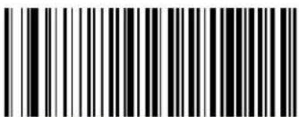 Code 39 Quiet Zones = Quiet Zone on one side Code 39 Quiet Zones = Quiet Zone on one side | |
 Code 39 Quiet Zones = Quiet Zones on two sides Code 39 Quiet Zones = Quiet Zones on two sides | |
 Code 39 Quiet Zones = Auto Code 39 Quiet Zones = Auto |  |
 Code 39 Quiet Zones = Virtual Quiet Zones on two sides Code 39 Quiet Zones = Virtual Quiet Zones on two sides | |
 Code 39 Quiet Zones = Small Quiet Zones on two sides Code 39 Quiet Zones = Small Quiet Zones on two sides |
Code 39 Minimum Reads
This feature specifies the minimum number of consecutive times a Code 39 label must be decoded before it is accepted as good read.
 Code 39 Minimum Reads = 1 Code 39 Minimum Reads = 1 | |
 Code 39 Minimum Reads = 2 Code 39 Minimum Reads = 2 |  |
 Code 39 Minimum Reads = 3 Code 39 Minimum Reads = 3 | |
 Code 39 Minimum Reads = 4 Code 39 Minimum Reads = 4 |
ENTER/EXIT PROGRAMMING MODE Code 39 Decoding Level
Code 39 Decoding Level
Decoding Levels are used to configure a barcode symbology decoder to be very aggressive to very conservative depending on a particular customer's needs. See page 242 for more information on this feature.

This configuration item applies to Code 39 and Code 32.
 Code 39 Decoding Level = 1 (Conservative) Code 39 Decoding Level = 1 (Conservative) | |
 Code 39 Decoding Level = 2 Code 39 Decoding Level = 2 | |
 Code 39 Decoding Level = 3 Code 39 Decoding Level = 3 |  |
 Code 39 Decoding Level = 4 Code 39 Decoding Level = 4 | |
 Code 39 Decoding Level = 5 (Aggressive) Code 39 Decoding Level = 5 (Aggressive) |
Code 39 Length Control
This feature specifies either variable length decoding or fixed length decoding for the Code 39 symbology.
Variable Length. For variable length decoding, a minimum and maximum length may be set.
Fixed Length. For fixed length decoding, two different lengths may be set.

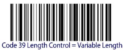

Code 39 Set Length 1
This feature specifies one of the barcode lengths for Code 39 Length Control. Length 1 is the minimum label length if in Variable Length Mode, or the first fixed length if in Fixed Length Mode. Length includes the barcode's data characters only. The length can be set from 0 to 50 characters.
Table 2 provides examples for setting Length 1. See page 242 for detailed instructions on setting this feature.
Table 2. Code 39 Length 1 Setting Examples
| STEP ACTION EXAMPLES | ||||
| 1 Desired Setting | 00 Characters 07 | Characters 15 Characters | 50 Characters | |
| 2 Scan ENTER/EXIT PROGRAMMING MODE | ||||
| 3 Scan SELECT CODE 39 LENGTH 1 SETTING | ||||
| 4 | Scan Two Characters FromAppendix D, Keypad | ‘0’ and ‘0’ | ‘0’ and ‘7’ | ‘1’ and ‘5’ |
| 5 Scan ENTER/EXIT PROGRAMMING MODE | ||||

Select Code 39 Set Length 1 Setting
Make a mistake? Scan the CANCEL barcode to abort and not save the entry string. You can then start again at the beginning.

CANCEL
DEFAULT
02 = Length 1 is 2 Characters
Code 39 Set Length 2
This feature specifies one of the barcode lengths for Code 39 Length Control. Length 2 is the maximum label length if in Variable Length Mode, or the second fixed length if in Fixed Length Mode. Length includes the barcode's check, data, and full-ASCII shift characters. The length does not include start/stop characters.
Table 3 provides examples for setting Length 2. See page 243 for detailed instructions on setting this feature.
Table 3. Code 39 Length 2 Setting Examples
| STEP ACTION EXAMPLES | ||||
| 1 Desired Setting | 00 (Ignore This Length) | 07 Characters 15 | Characters 50 Characters | Characters |
| 2 Scan ENTER/EXIT PROGRAMMING MODE | ||||
| 3 Scan SELECT CODE 39 LENGTH 2 SETTING | ||||
| 4 | Scan Two Characters From Appendix D, Keypad | ‘0’ and ‘0’ | ‘0’ and ‘7’ | ‘1’ and ‘5’ |
| 5 Scan ENTER/EXIT PROGRAMMING MODE | ||||

Select Code 39Length 2 Setting
Make a mistake? Scan the CANCEL barcode to abort and not save the entry string. You can then start again at the beginning.

CANCEL
DEFAULT
50 = Length 2 is 50 Characters

ENTER/EXIT PROGRAMMING MODE Code 39 Interdigit Ratio
Code 39 Interdigit Ratio
This feature specifies the ratio between an intercharacter space and module for Code 39 labels.
 Code 39 Interdigit Ratio = Disable Code 39 Interdigit Ratio = Disable | |
 Code 39 Interdigit Ratio = 1 Code 39 Interdigit Ratio = 1 | |
 Code 39 Interdigit Ratio = 2 Code 39 Interdigit Ratio = 2 | |
 Code 39 Interdigit Ratio = 3 Code 39 Interdigit Ratio = 3 | |
 |  Code 39 Interdigit Ratio = 4 Code 39 Interdigit Ratio = 4 |
 Code 39 Interdigit Ratio = 5 Code 39 Interdigit Ratio = 5 |
Code 39 ENTER/EXIT PROGRAMMING MODE
Code 39 Interdigit Ratio (continued)
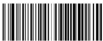 Code 39 Interdigit Ratio = 6 Code 39 Interdigit Ratio = 6 | |
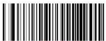 Code 39 Interdigit Ratio = 7 Code 39 Interdigit Ratio = 7 | |
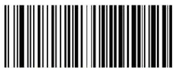 Code 39 Interdigit Ratio = 8 Code 39 Interdigit Ratio = 8 | |
 Code 39 Interdigit Ratio = 9 Code 39 Interdigit Ratio = 9 | |
 Code 39 Interdigit Ratio = 10 Code 39 Interdigit Ratio = 10 |

ENTER/EXIT PROGRAMMING MODE Code 39 Character Correlation
Code 39 Character Correlation
When correlation is enabled, the barcode reader will combine label data from multiple scans when decoding. Enabling correlation will help the scanner read labels that have some spots and/or voids. It may also help read labels that have damaged areas. Enabling correlation will also increase the chances that a label will be read incorrectly.

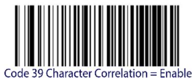
Code 39 Stitching
This option enables/disables stitching for Code 39 labels. When parts of a Code 39 barcode are presented to the reader with this feature enabled, the barcode parts will be assembled by the reader's software, and the data will be decoded if all barcode proofing requirements are met.
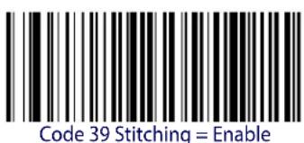


CODE 32 (ITAL PHARMACEUTICAL CODE)
The following options apply to the Code 32 (Italian Pharmaceutical Code) symbology.
Code 32 Enable/Disable
When disabled, the reader will not read Code 32 barcodes.

Code 32 = Enable

Code 32 = Disable
Code 32 Feature Setting Exceptions

The following features are set for Code 32 by using these Code 39 settings:
"Code 39 Quiet Zones" on page 109
"Code 39 Minimum Reads" on page 110
"Code 39 Decoding Level" on page 111
"Code 39 Interdigit Ratio" on page 115
"Code 39 Character Correlation" on page 117
"Code 39 Stitching" on page 117

ENTER/EXIT PROGRAMMING MODE Code 32 Check Char Transmission
Code 32 Check Char Transmission
Enable this option to transmit the check character along with Code 32 barcode data.
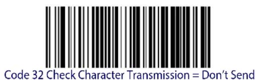

Code 32 Check Character Transmission = Send
Code 32 Start/Stop Character Transmission
This option enables/disables transmission of Code 32 start and stop characters.


Code 32 Start/Stop Character Transmission = Transmit
CODE 39 CIP (FRENCH PHARMACEUTICAL)
The following options apply to the Code 39 CIP symbology.
Code 39 CIP Enable/Disable
Enables/Disables ability of the reader to decode Code 39 CIP labels.


Code 39 CIP = Enable

ENTER/EXIT PROGRAMMING MODE Code 128 Enable/Disable
CODE 128
The following options apply to the Code 128 symbology.
Code 128 Enable/Disable
When disabled, the reader will not read Code 128 barcodes.
 Code 128 = Disable Code 128 = Disable | |
 Code 128 = Enable Code 128 = Enable |  |
Expand Code 128 to Code 39
This feature enables/disables expansion of Code 128 labels to Code 39 labels.
 |  Code 128 to Code 39 = Don't Expand Code 128 to Code 39 = Don't Expand |
 Code 128 to Code 39 = Expand Code 128 to Code 39 = Expand |
Code 128 Check Character Transmission
Enable this option to transmit the check character along with Code 128 barcode data.


Code 128 Check Character Transmission = Don't Send
Code 128 Function Character Transmission
Enables/disables transmission of Code128 function characters 1, 2, 3, and 4.


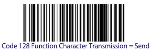
Code 128 Function Character Transmission = Don't Send

ENTER/EXIT PROGRAMMING MODE Code 128 Sub-Code Change Transmission
Code 128 Sub-Code Change Transmission
Enables/disables the transmission of "Sub-Code exchange" characters (NOT transmitted by standard decoding).


Code 128 Sub-Code Change Transmission = Disable
Code 128 Quiet Zones
This feature specifies the number of quiet zones for Code 128 labels. Quiet zones are blank areas at the ends of a barcode and are typically 10 times the width of the narrowest bar or space in the label.
 Code 128 Quiet Zones = No Quiet Zones Code 128 Quiet Zones = No Quiet Zones | |
 Code 128 Quiet Zones = Quiet Zone on one side Code 128 Quiet Zones = Quiet Zone on one side | |
 Code 128 Quiet Zones = Quiet Zones on two sides Code 128 Quiet Zones = Quiet Zones on two sides | |
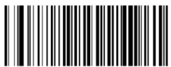 Code 128 Quiet Zones = Auto Code 128 Quiet Zones = Auto |  |
 Code 128 Quiet Zones = Virtual Quiet Zones on two sides Code 128 Quiet Zones = Virtual Quiet Zones on two sides |
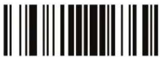
ENTER/EXIT PROGRAMMING MODE Code 128 Minimum Reads
Code 128 Minimum Reads
This feature specifies the minimum number of consecutive times a Code 128 label must be decoded before it is accepted as good read.
 | 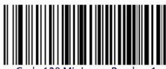 Code 128 Minimum Reads = 1 Code 128 Minimum Reads = 1 |
 Code 128 Minimum Reads = 2 Code 128 Minimum Reads = 2 | |
 Code 128 Minimum Reads = 3 Code 128 Minimum Reads = 3 | |
 Code 128 Minimum Reads = 4 Code 128 Minimum Reads = 4 |
Code 128 Decoding Level
Decoding Levels are used to configure a barcode symbology decoder to be very aggressive to very conservative depending on a particular customer's needs. See page 242 for more information on this feature.
 Code 128 Decoding Level = 1 (Conservative) Code 128 Decoding Level = 1 (Conservative) | |
 Code 128 Decoding Level = 2 Code 128 Decoding Level = 2 | |
 Code 128 Decoding Level = 3 Code 128 Decoding Level = 3 |  |
 Code 128 Decoding Level = 4 Code 128 Decoding Level = 4 | |
 Code 128 Decoding Level = 5 (Aggressive) Code 128 Decoding Level = 5 (Aggressive) |
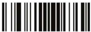
ENTER/EXIT PROGRAMMING MODE Code 128 Length Control
Code 128 Length Control
This feature specifies either variable length decoding or fixed length decoding for the Code 128 symbology. See page 242 for more information..
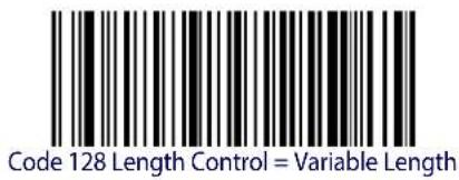

Code 128 Set Length 1
Specifies one of the barcode lengths for Code 128 Length Control. Length 1 is the minimum label length if in Variable Length Mode, or the first fixed length if in Fixed Length Mode. Length includes the barcode's data characters only. The length can be set from 1 to 80 characters.
Table 4 provides some examples for setting Length 1. See page 242 for detailed instructions on setting this feature.
Table 4. Code 128 Length 1 Setting Examples
| STEP ACTION EXAMPLES | ||||
| 1 Desired Setting | 01 Character | 07 Characters | 15 Characters | 80 Characters |
| 2 Scan ENTER/EXIT PROGRAMMING MODE | ||||
| 3 Scan SELECT CODE 128 LENGTH 1 SETTING | ||||
| 4 | Scan Two Characters From Appendix D, Keypad | ‘0’ and ‘1’ | ‘0’ and ‘7’ | ‘1’ and ‘5’ |
| 5 Scan ENTER/EXIT PROGRAMMING MODE | ||||
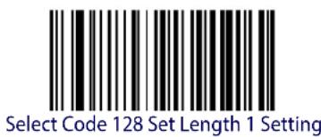
Make a mistake? Scan the CANCEL barcode to abort and not save the entry string. You can then start again at the beginning.

DEFAULT
01 = Length 1 is 1 Character
Code 128 Set Length 2
This feature specifies one of the barcode lengths for Code 128 Length Control. Length 2 is the maximum label length if in Variable Length Mode, or the second fixed length if in Fixed Length Mode. Length includes the barcode's data characters only.
The length can be set from 1 to 80 characters. A setting of 0 specifies to ignore this length (only one fixed length).
Table 5 provides examples for setting Length 2. See page 243 for detailed instructions on setting this feature.
Table 5. Code 128 Length 2 Setting Examples
| STEP ACTION EXAMPLES | ||||
| 1 Desired Setting | 00 (Ignore This Length) | 07 Characters 15 | Characters 80 Characters | |
| 2 Scan ENTER/EXIT PROGRAMMING MODE | ||||
| 3 Scan SELECT CODE 128 LENGTH 2 SETTING | ||||
| 4 | Scan Two Characters From Appendix D, Keypad | ‘0’ and ‘0’ ‘0’ and ‘7’ ‘0’ and ‘F’ ‘5’ AND 0’ | ||
| 5 Scan ENTER/EXIT PROGRAMMING MODE | ||||

Select Code 128 Length 2 Setting
Make a mistake? Scan the CANCEL barcode to abort and not save the entry string. You can then start again at the beginning.

CANCEL
DEFAULT
80 = Length 2 is 80 Characters
Code 128 Character Correlation
When correlation is enabled, the barcode reader will combine label data from multiple scans when decoding. Enabling correlation will help the scanner read labels that have some spots and/or voids. It may also help read labels that have damaged areas. Enabling correlation will also increase the chances that a label will be read incorrectly.


Code 128 Character Correlation = Disable
Code 128 Stitching
This option enables/disables stitching for Code 128 labels. When parts of a Code 128 barcode are presented to the reader with this feature enabled, the barcode parts will be assembled by the reader's software, and the data will be decoded if all barcode proofing requirements are met.


Code 128 Stitching = Disable
Code 128 Stitching = Enable

GS1-128
The following options apply to the GS1-128 symbology. (Also known as USS-128, GS1-128, GTIN-128, UCC-128, EAN-128.)
GS1-128 Enable
This option enables/disables the ability of the reader to translate GS1-128 labels to the GS1-128 data format. Options are:
- Transmit GS1-128 labels in Code 128 data format.
- Transmit GS1-128 labels in GS1-128 data format.
- Do not transmit GS1-128 labels.
 GS1-128 = Transmit in Code 128 data format GS1-128 = Transmit in Code 128 data format | |
 GS1-128 = Transmit in GS1-128 data format GS1-128 = Transmit in GS1-128 data format |  |
 GS1-128 = Do not transmit GS1-128 labels GS1-128 = Do not transmit GS1-128 labels |
CODE ISBT 128
The following options apply to the ISBT 128 symbology.
ISBT 128 Concatenation
Use this option to enable/disable ISBT128 concatenation of 2 labels.
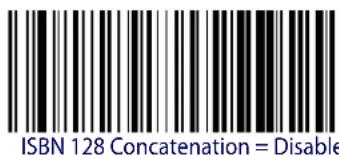

ISBT 128 Force Concatenation
When enabled, this feature forces concatenation for ISBT.

This option is only valid when ISBT 128 Concatenation is enabled.
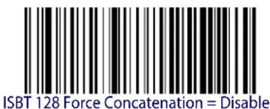

ISBT 128 Force Concatenation = Enable
ENTER/EXIT PROGRAMMING MODE ISBT 128 Concatenation Mode
ISBT 128 Concatenation Mode
Specifies the concatenation mode between Static and Dynamic.

This option is only valid when ISBT 128 Concatenation is enabled (see page 132).


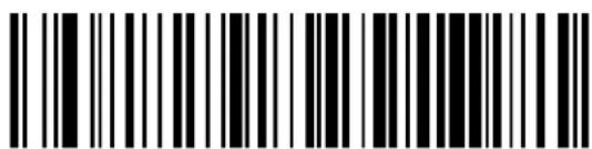
ISBT 128 Concatenation Mode = Dynamic
ISBT 128 Dynamic Concatenation Timeout
Specifies the timeout used by the ISBT 128 Dynamic Concatenation Mode.
 ISBT 128 Dynamic Concatenation Timeout = 50 msec ISBT 128 Dynamic Concatenation Timeout = 50 msec | |
 ISBT 128 Dynamic Concatenation Timeout = 100 msec ISBT 128 Dynamic Concatenation Timeout = 100 msec | |
 |  ISBT 128 Dynamic Concatenation Timeout = 200 msec ISBT 128 Dynamic Concatenation Timeout = 200 msec |
 ISBT 128 Dynamic Concatenation Timeout = 500 msec ISBT 128 Dynamic Concatenation Timeout = 500 msec | |
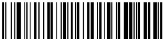 ISBT 128 Dynamic Concatenation Timeout = 750 msec ISBT 128 Dynamic Concatenation Timeout = 750 msec | |
 ISBT 128 Dynamic Concatenation Timeout = 1 second ISBT 128 Dynamic Concatenation Timeout = 1 second |

ENTER/EXIT PROGRAMMING MODE Codablock F Enable/Disable
CODABLOCK F
The following options apply to the Codablock F symbology.
Codablock F Enable/Disable
Enables/Disables ability of reader to decode Codablock F labels.
 |  Codablock F = Disable Codablock F = Disable |
 Codablock F = Enable Codablock F = Enable |
Codablock F EAN Enable/Disable
Enables/Disables the Codablock F EAN subtype (code with FNC1 in the first position)..
 |  Codablock F EAN = Disable Codablock F EAN = Disable |
Codablock F AIM Check
Specifies if Check Digit calculation algorithm is AIM compliant or not.
 Codablock F AIM Check = Disable Codablock F AIM Check = Disable | |
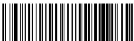 Codablock F AIM Check = Enable Check C Codablock F AIM Check = Enable Check C |  |
Codablock F Length Control
This feature specifies either variable length decoding or fixed length decoding for the Codablock F symbology.
Variable Length. For variable length decoding, a minimum and maximum length may be set.
Fixed Length. For fixed length decoding, two different lengths may be set.
 |  Codablock F Length Control = Variable Length Codablock F Length Control = Variable Length |
 Codablock F = Fixed Length Codablock F = Fixed Length |
Codablock F Set Length 1
Specifies one of the barcode lengths for Codablock F Length Control. Length 1 is the minimum label length if in Variable Length Mode, or the first fixed length if in Fixed Length Mode. Length includes the barcode's data characters only. Characters can be set from 03 to 255 characters.
Table 6 provides some examples for setting Length 1. See page 242 for detailed instructions on setting this feature.
Table 6. CODABLOCK F Length 1 Setting Examples
| STEP ACTION EXAMPLES | ||||
| 1 Desired Setting | 03 Characters 07 | Characters 15 Characters | 50 Characters | |
| 2 Scan ENTER/EXIT PROGRAMMING MODE | ||||
| 3 Scan SELECT CODABLOCK F LENGTH 1 SETTING | ||||
| 4 | Scan Three Characters From Appendix D, Keypad | ‘0’, ‘0’ and ‘3’ | ‘0’, ‘0’ and ‘7’ | ‘0”,‘1’ and ‘5’ |
| 5 Scan ENTER/EXIT PROGRAMMING MODE | ||||
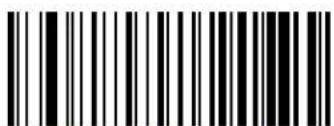
Select Codablock F Length 1 Setting
Make a mistake? Scan the CANCEL barcode to abort and not save the entry string. You can then start again at the beginning.

CANCEL
DEFAULT
03 = Length 1 is 3 Characters
Codablock F Set Length 2
This feature specifies one of the barcode lengths for Codablock F Length Control. Length 2 is the maximum label length if in Variable Length Mode, or the second fixed length if in Fixed Length Mode. Length includes the barcode's check, data, and full-ASCII shift characters. The length does not include start/stop characters.
Table 7 provides examples for setting Length 2. See page 243 for detailed instructions on setting this feature.
Table 7. CODABLOCK F Length 2 Setting Examples
| STEP ACTION EXAMPLES | ||||
| 1 Desired Setting | 00 (Ignore This Length) | 07 Characters 15 | Characters 50 Characters | Characters |
| 2 Scan ENTER/EXIT PROGRAMMING MODE | ||||
| 3 Scan SELECT CODABLOCK F LENGTH 2 SETTING | ||||
| 4 | Scan Three Characters From Appendix D, Keypad | ‘0’, ‘0’ and ‘0’ | ‘0’, ‘0’ and ‘7’ | ‘0”,‘1’ and ‘5’ |
| 5 Scan ENTER/EXIT PROGRAMMING MODE | ||||

Select Codablock F Length 2 Setting
Make a mistake? Scan the CANCEL barcode to abort and not save the entry string. You can then start again at the beginning.

CANCEL
DEFAULT
100 = Length 2 is 100 Characters

ENTER/EXIT PROGRAMMING MODE I 2 of 5 Enable/Disable
INTERLEAVED 2 OF 5 (I 2 OF 5)
The following options apply to the I 2 of 5 symbology.
I 2 of 5 Enable/Disable
When disabled, the reader will not read I 2 of 5 barcodes.


12 of 5 = Enable
I 2 of 5 Check Character Calculation
This option enables/disables calculation and verification of an optional I 2 of 5 check character.


12 of 5 Check Character Calculation = Disable

12 of 5 Check Character Calculation = Check German Parcel
I 2 of 5 Check Character Calculation (continued)
| 12 of 5 Check Character Calculation = Check DHL | |
| 12 of 5 Check Character Calculation = Check Daimler Chrysler | |
| 12 of 5 Check Character Calculation = Check Bosch | |
| 12 of 5 Check Character Calculation = Italian Post |
I 2 of 5 Check Character Transmission
Enable this option to transmit the check character along with I 2 of 5 barcode data.
| 12 of 5 Check Character Transmission = Don't Send | |
| 12 of 5 Check Character Transmission = Send | DEFAULT |

ENTER/EXIT PROGRAMMING MODE I 2 of 5 Minimum Reads
I 2 of 5 Minimum Reads
This feature specifies the minimum number of consecutive times an 12 of 5 label must be decoded before it is accepted as good read.
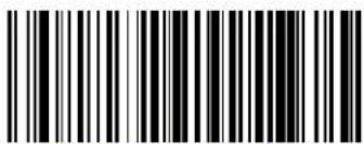 12 of 5 Minimum Reads = 1 12 of 5 Minimum Reads = 1 | |
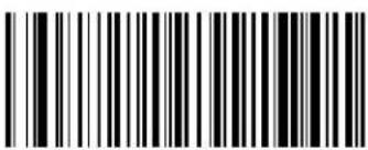 12 of 5 Minimum Reads = 2 12 of 5 Minimum Reads = 2 |  |
 12 of 5 Minimum Reads = 3 12 of 5 Minimum Reads = 3 | |
 12 of 5 Minimum Reads = 4 12 of 5 Minimum Reads = 4 |

2 of 5 Decoding Level
This configuration item applies to Interleaved 2 of 5, China Postal Code and Standard 2 of 5.
Decoding Levels are used to configure a barcode symbology decoder to be very aggressive to very conservative depending on a particular customer's needs. See page 242 for more information on this feature.


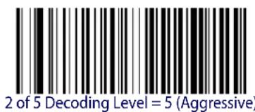


ENTER/EXIT PROGRAMMING MODE I 2 of 5 Length Control
12 of 5 Length Control
This feature specifies either variable length decoding or fixed length decoding for the 12 of 5 symbology.
Variable Length. For variable length decoding, a minimum and maximum length may be set.
Fixed Length. For fixed length decoding, two different lengths may be set.

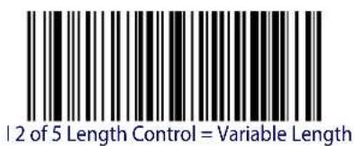

I 2 of 5 Set Length 1
This feature specifies one of the barcode lengths for 12 of 5 Length Control. Length 1 is the minimum label length if in Variable Length Mode, or the first fixed length if in Fixed Length Mode. The length includes the barcode's check and data characters. The length can be set from 2 to 50 characters in increments of two.
Table 8 provides some examples for setting Length 1. See page 242 for detailed instructions on setting this feature.
Table 8.12 of 5 Length 1 Setting Examples
| STEP ACTION EXAMPLES | |||||
| 1 Desired Setting | 2 Characters 6 | Characters 14 | Characters 50 | Characters | |
| 2 | Pad with leading zeroes to yield two digits | 02 06 14 50 | |||
| 3 Scan ENTER/EXIT PROGRAMMING MODE | |||||
| 4 Scan SELECT I 2 of 5 LENGTH 1 SETTING | |||||
| 5 | Scan Two Characters From Appendix D, Keypad | ‘0’ and ‘2’ | ‘0’ and ‘6’ | ‘1’ and ‘4’ | ‘5’ AND ‘0’ |
| 6 Scan ENTER/EXIT PROGRAMMING MODE | |||||

Select | 2 of 5 Length 1 Setting
Make a mistake? Scan the CANCEL barcode to abort and not save the entry string. You can then start again at the beginning.
CANCEL
DEFAULT
06 = Length 1 is 6 Characters
12 of 5 Set Length 2
This feature specifies one of the barcode lengths for 12 of 5 Length Control. Length 2 is the maximum label length if in Variable Length Mode, or the second fixed length if in Fixed Length Mode. The length includes the barcode's check and data characters.
The length can be set from 2 to 50 characters. A setting of 0 specifies to ignore this length (only one fixed length).
Table 9 provides examples for setting Length 2. See page 243 for detailed instructions on setting this feature.
Table 9.12 of 5 Length 2 Setting Examples
| STEP ACTION EXAMPLES | ||||
| 1 Desired Setting | Ignore This Length | 4 Characters 14 | Characters 50 Characters | |
| 2 Pad with leading zeroes to yield two digits | 00 04 14 50 | |||
| 3 Scan ENTER/EXIT PROGRAMMING MODE | ||||
| 4 Scan SELECT I 2 OF 5 LENGTH 2 SETTING | ||||
| 5 Scan Two Characters From Appendix D, Keypad | ‘0’ and ‘0’ ‘0’ and ‘4’ ‘1’ and ‘4’ ‘5’ AND ‘0’ | |||
| 6 Scan ENTER/EXIT PROGRAMMING MODE | ||||

Select 12 of 5 Length 2 Setting
Make a mistake? Scan the CANCEL barcode to abort and not save the entry string. You can then start again at the beginning.

CANCEL
DEFAULT
50 = Length 2 is 50 Characters
I 2 of 5 Character Correlation
When correlation is enabled, the barcode reader will combine label data from multiple scans when decoding. Enabling correlation will help the scanner read labels that have some spots and/or voids. It may also help read labels that have damaged areas. Enabling correlation will also increase the chances that a label will be read incorrectly.


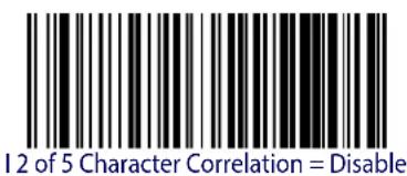
I 2 of 5 Stitching
This option enables/disables stitching for I 2 of 5 labels. When parts of a I 2 of 5 barcode are presented to the reader with this feature enabled, the barcode parts will be assembled by the reader's software, and the data will be decoded if all barcode proofing requirements are met.

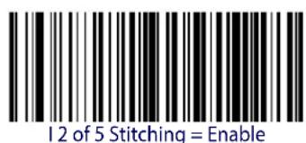


ENTER/EXIT PROGRAMMING MODE Follett 2 of 5 Enable/Disable
FOLLETT 2 OF 5
The following options apply to the Follett 2 of 5 symbology.
Follett 2 of 5 Enable/Disable
Enables/Disables ability of imager to decode Follett 2 of 5 labels.


Follett 2 of 5 = Enable
Follett 2 of 5 = Disable
INTERLEAVED 2 OF 5 CIP HR
The following options apply to the Interleaved 2 of 5 CIP HR symbology.
Interleaved 2 of 5 CIP HR Enable/Disable
Enables/Disables ability of reader to decode Interleaved 2 of 5 CIP HR labels.
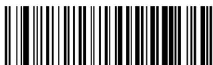

Interleaved 2 of 5 CIP HR = Enable
Interleaved 2 of 5 CIP HR = Disable
STANDARD 2 OF 5
The following options apply to the Standard 2 of 5 symbology.
Standard 2 of 5 Enable/Disable
When disabled, the reader will not read Standard 2 of 5 barcodes.


Standard 2 of 5 Check Character Calculation
This option enables/disables calculation and verification of an optional Standard 2 of 5 check character.

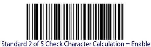
Standard 2 of 5 Check Character Transmission
This feature enables/disables transmission of an optional Standard 2 of 5 check character.
 Standard 2 of 5 Check Character Transmission = Don’t Send Standard 2 of 5 Check Character Transmission = Don’t Send | |
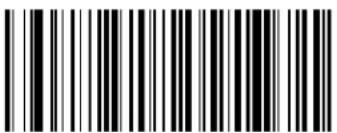 Standard 2 of 5 Check Character Transmission = Send Standard 2 of 5 Check Character Transmission = Send |  |
Standard 2 of 5 Minimum Reads
This feature specifies the minimum number of consecutive times a Standard 2 of 5 label must be decoded before it is accepted as good read.
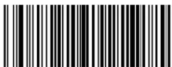 Standard 2 of 5 Minimum Reads = 1 Standard 2 of 5 Minimum Reads = 1 | |
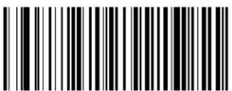 Standard 2 of 5 Minimum Reads = 2 Standard 2 of 5 Minimum Reads = 2 |  |
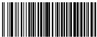 Standard 2 of 5 Minimum Reads = 3 Standard 2 of 5 Minimum Reads = 3 | |
 Standard 2 of 5 Minimum Reads = 4 Standard 2 of 5 Minimum Reads = 4 |
Standard 2 of 5 Decoding Level

The Standard 2 of 5 Decoding Level feature is set using "2 of 5 Decoding Level" on page 142.
Standard 2 of 5 Length Control
This feature specifies either variable length decoding or fixed length decoding for the Standard 2 of 5 symbology.
Variable Length. For variable length decoding, a minimum and maximum length may be set.
Fixed Length. For fixed length decoding, two different lengths may be set.


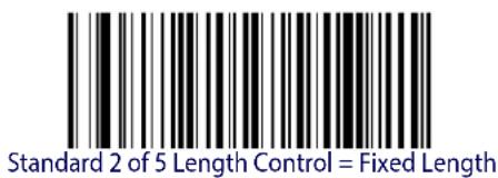
Standard 2 of 5 Length Control = Variable Length
Standard 2 of 5 Set Length 1
This feature specifies one of the barcode lengths for Standard 2 of 5 Length Control. Length 1 is the minimum label length if in Variable Length Mode, or the first fixed length if in Fixed Length Mode. Length includes the barcode's check and data characters. The length can be set from 1 to 50 characters.
Table 10 provides some examples for setting Length 1. See page 242 if you want detailed instructions on setting this feature.
Table 10. Standard 2 of 5 Length 1 Setting Examples
| STEP ACTION EXAMPLES | ||||
| 1 Desired Setting | 01 Character | 07 Characters | 15 Characters | 50 Characters |
| 2 Scan ENTER/EXIT PROGRAMMING MODE | ||||
| 3 Scan SELECT STANDARD 2 OF 5 LENGTH 1 SETTING | ||||
| 4 | Scan Two Characters From Appendix D, Keypad | ‘0’ and ‘1’ | ‘0’ and ‘7’ | ‘1’ and ‘5’ |
| 5 Scan ENTER/EXIT PROGRAMMING MODE | ||||

Select Standard 2 of 5 Length 1 Setting
Make a mistake? Scan the CANCEL barcode to abort and not save the entry string. You can then start again at the beginning.

CANCEL
DEFAULT
08 = Length 1 is 8 Characters
Standard 2 of 5 Set Length 2
This feature specifies one of the barcode lengths for Standard 2 of 5 Length Control. Length 2 is the maximum label length if in Variable Length Mode, or the second fixed length if in Fixed Length Mode. Length includes the barcode's check and data characters.
The length can be set from 1 to 50 characters. A setting of 0 specifies to ignore this length (only one fixed length).
Table 11 provides examples for setting Length 2. See page 243 for detailed instructions on setting this feature.
Table 11. Standard 2 of 5 Length 2 Setting Examples
| STEP ACTION EXAMPLES | |||||
| 1 | Desired Setting (pad with leading zeroes) | 00 (Ignore This Length) | 07 Characters 15 | Characters 50 Characters | |
| 2 Scan ENTER/EXIT PROGRAMMING MODE | |||||
| 3 Scan SELECT STANDARD 2 OF 5 LENGTH 2 SETTING | |||||
| 4 | Scan Two Characters From Appendix D, Keypad | ‘0’ and ‘0’ | ‘0’ and ‘7’ | ‘1’ and ‘5’ | ‘5’ AND ‘0’ |
| 5 Scan ENTER/EXIT PROGRAMMING MODE | |||||

Select Standard 2 of 5 Length 2 Setting
Make a mistake? Scan the CANCEL barcode to abort and not save the entry string. You can then start again at the beginning.
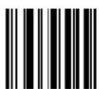
CANCEL
DEFAULT
50 = Length 2 is 50 Characters
Standard 2 of 5 Character Correlation
When correlation is enabled, the barcode reader will combine label data from multiple scans when decoding. Enabling correlation will help the scanner read labels that have some spots and/or voids. It may also help read labels that have damaged areas. Enabling correlation will also increase the chances that a label will be read incorrectly.

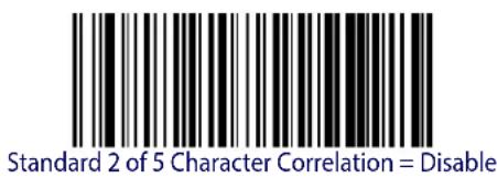

Standard 2 of 5 Character Correlation = Enable
Standard 2 of 5 Stitching
This option enables/disables stitching for Standard 2 of 5 labels. When parts of a Standard 2 of 5 barcode are presented to the reader with this feature enabled, the barcode parts will be assembled by the reader's software, and the data will be decoded if all barcode proofing requirements are met.


Standard 2 of 5 Stitching = Disable
Standard 2 of 5 Stitching = Enable
INDUSTRIAL 2 OF 5
The following options apply to the Industrial 2 of 5 symbology.
Industrial 2 of 5 Enable/Disable
Enables/Disables ability of reader to decode Industrial 2 of 5 labels.


Industrial 2 of 5 = Enable
Industrial 2 of 5 = Disable
Industrial 2 of 5 Check Character Calculation
Enables/Disables calculation and verification of an optional Industrial 2 of 5 check character.

Industrial 2 of 5 Check Character Calculation = Disable

Industrial 2 of 5 Check Character Calculation = Enable
Industrial 2 of 5 Check Character Transmission
Enables/disables transmission of an Industrial 2 of 5 check character.
| Industrial 2 of 5 Check Character Transmission = Disable | |
 Industrial 2 of 5 Check Character Transmission = Enable Industrial 2 of 5 Check Character Transmission = Enable |  |
Industrial 2 of 5 Length Control
This feature specifies either variable length decoding or fixed length decoding for the Industrial 2 of 5 symbology.
Variable Length. For variable length decoding, a minimum and maximum length may be set.
Fixed Length. For fixed length decoding, two different lengths may be set.
 |  Industrial 2 of 5 Length Control = Variable Length Industrial 2 of 5 Length Control = Variable Length |
 Industrial 2 of 5 = Fixed Length Industrial 2 of 5 = Fixed Length |
Industrial 2 of 5 Set Length 1
This feature specifies one of the barcode lengths for Industrial 2 of 5 Length Control. Length 1 is the minimum label length if in Variable Length Mode, or the first fixed length if in Fixed Length Mode. Length includes the barcode's data characters only. The length can be set from 0 to 50 characters.
Table 12 provides some examples for setting Length 1. See page 242 if you want detailed instructions on setting this feature.
Table 12. Industrial 2 of 5 Length 1 Setting Examples
| STEP ACTION EXAMPLES | ||||
| 1 Desired Setting | 00 Characters | 07 Characters | 15 Characters | 50 Characters |
| 2 Scan ENTER/EXIT PROGRAMMING MODE | ||||
| 3 Scan SELECT INDUSTRIAL 2 OF 5 LENGTH 1 SETTING | ||||
| 4 | Scan Two Characters From Appendix D, Keypad | ‘0’ and ‘0’ | ‘0’ and ‘7’ | ‘1’ and ‘5’ |
| 5 Scan ENTER/EXIT PROGRAMMING MODE | ||||

Select Industrial 2 of 5 Set Length 1 Setting
Make a mistake? Scan the CANCEL barcode to abort and not save the entry string. You can then start again at the beginning.

CANCEL
DEFAULT
01 = Length 1 is 1 Character
Industrial 2 of 5 Set Length 2
This feature specifies one of the barcode lengths for Industrial 2 of 5 Length Control. Length 2 is the maximum label length if in Variable Length Mode, or the second fixed length if in Fixed Length Mode. Length includes the barcode's check, data, and full-ASCII shift characters. The length does not include start/stop characters.
The length can be set from 1 to 50 characters. A setting of 0 specifies to ignore this length (only one fixed length).
Table 13 provides examples for setting Length 2. See page 243 for detailed instructions on setting this feature.
Table 13. Industrial 2 of 5 Length 2 Setting Examples
| STEP ACTION EXAMPLES | |||||
| 1 Desired Setting | 00 (Ignore This Length) | 07 Characters 15 | Characters 50 Characters | ||
| 2 Scan ENTER/EXIT PROGRAMMING MODE | |||||
| 3 Scan SELECT INDUSTRIAL 2 OF 5 LENGTH 2 SETTING | |||||
| 4 | Scan Two Characters From Appendix D, Keypad | ‘0’ and ‘0’ | ‘0’ and ‘7’ | ‘1’ and ‘5’ | ‘5’ AND ‘0’ |
| 5 Scan ENTER/EXIT PROGRAMMING MODE | |||||

Select Industrial 2 of5 Length 2 Setting
Make a mistake? Scan the CANCEL barcode to abort and not save the entry string. You can then start again at the beginning.

CANCEL
DEFAULT
50 = Length 2 is 50 Characters
Industrial 2 of 5 Minimum Reads
This feature specifies the minimum number of consecutive times an Industrial 2 of 5 label must be decoded before it is accepted as good read.
 | 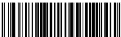 Industrial 2 of 5 Minimum Reads = 1 Industrial 2 of 5 Minimum Reads = 1 |
 Industrial 2 of 5 Minimum Reads = 2 Industrial 2 of 5 Minimum Reads = 2 | |
 Industrial 2 of 5 Minimum Reads = 3 Industrial 2 of 5 Minimum Reads = 3 | |
 Industrial 2 of 5 Minimum Reads = 4 Industrial 2 of 5 Minimum Reads = 4 |
Industrial 2 of 5 Stitching
Enables/disables fixed length stitching for Industrial 2 of 5.
 |  Industrial 2 of 5 Stitching = Disable Industrial 2 of 5 Stitching = Disable |
 Industrial 2 of 5 Stitching = Enable Industrial 2 of 5 Stitching = Enable |
Industrial 2 of 5 Character Correlation
Enable/disables character correlation for Industrial 2 of 5.


Industrial 2 of 5 Character Correlation = Enable
CODE IATA
The following options apply to the IATA symbology.
IATA Enable/Disable
Enables/Disables the ability of the reader to decode IATA labels.

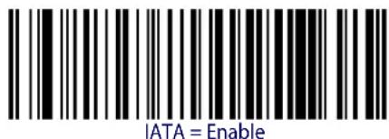

IATA Check Character Transmission
Enables/Disables calculation and verification of an optional Industrial 2 of 5 check character.
| IATA Check Character Transmission = Disable | |
 |  |

ENTER/EXIT PROGRAMMING MODE China Postal Code Enable/Disable
CHINA POSTAL CODE
The following options apply to the China Postal Code symbology.
China Postal Code Enable/Disable
When disabled, the reader will not read China Postal Code barcodes.

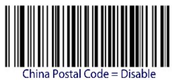

China Postal Code Check Character Calculation
This option enables/disables calculation and verification of an optional China Postal Code check character.


China Postal Code Minimum Reads
This feature specifies the minimum number of consecutive times an China Postal Code label must be decoded before it is accepted as good read.
| China Postal Code Minimum Reads = 1 | |
 China Postal Code Minimum Reads = 2 China Postal Code Minimum Reads = 2 |  |
 China Postal Code Minimum Reads = 3 China Postal Code Minimum Reads = 3 | |
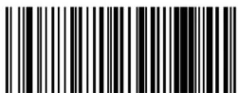 China Postal Code Minimum Reads = 4 China Postal Code Minimum Reads = 4 |
China Postal Code Decoding Level

The China Postal Code Decoding Level feature is set using "2 of 5 Decoding Level" on page 142.

ENTER/EXIT PROGRAMMING MODE China Postal Code Length Control
China Postal Code Length Control
This feature specifies either variable length decoding or fixed length decoding for the China Postal Code symbology.
Variable Length. For variable length decoding, a minimum and maximum length may be set.
Fixed Length. For fixed length decoding, two different lengths may be set.


China Postal Code Length Control = Variable Length
China Postal Code Set Length 1
This feature specifies one of the barcode lengths for China Postal Code Length Control. Length 1 is the minimum label length if in Variable Length Mode, or the first fixed length if in Fixed Length Mode. The length includes the barcode's check and data characters. The length can be set from 2 to 50 characters in increments of two.
Table 14 provides some examples for setting Length 1. See page 242 for detailed instructions on setting this feature.
Table 14. China Postal Code Length 1 Setting Examples
| STEP ACTION EXAMPLES | |||||
| 1 Desired Setting | 2 Characters 6 | Characters 14 | Characters 50 | Characters | |
| 2 | Pad with leading zeroes to yield two digits | 02 06 14 50 | |||
| 3 Scan ENTER/EXIT PROGRAMMING MODE | |||||
| 4 Scan SELECT China Postal Code LENGTH 1 SETTING | |||||
| 5 | Scan Two Characters From Appendix D, Keypad | ‘0’ and ‘2’ | ‘0’ and ‘6’ | ‘1’ and ‘4’ | ‘5’ AND ‘0’ |
| 6 Scan ENTER/EXIT PROGRAMMING MODE | |||||
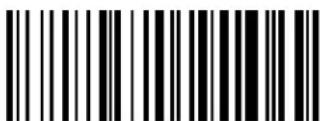
Select China Postal Code Length 1 Setting
Make a mistake? Scan the CANCEL barcode to abort and not save the entry string. You can then start again at the beginning.

CANCEL
DEFAULT
06 = Length 1 is 6 Characters
China Postal Code Set Length 2
This feature specifies one of the barcode lengths for China Postal Code Length Control. Length 2 is the maximum label length if in Variable Length Mode, or the second fixed length if in Fixed Length Mode. The length includes the barcode's check and data characters.
The length can be set from 2 to 50 characters. A setting of 0 specifies to ignore this length (only one fixed length).
Table 15 provides examples for setting Length 2. See page 243 for detailed instructions on setting this feature.
Table 15. China Postal Code Length 2 Setting Examples
| STEP ACTION EXAMPLES | ||||
| 1 Desired Setting | Ignore This Length | 4 Characters 14 | Characters 50 Characters | |
| 2 Pad with leading zeroes to yield two digits | 00 04 14 50 | |||
| 3 Scan ENTER/EXIT PROGRAMMING MODE | ||||
| 4 Scan SELECT China Postal Code LENGTH 2 SETTING | ||||
| 5 Scan Two Characters From Appendix D, Keypad | ‘0’ and ‘0’ | ‘0’ and ‘4’ | ‘1’ and ‘4’ | ‘5’ AND ‘0’ |
| 6 Scan ENTER/EXIT PROGRAMMING MODE | ||||

Select China Postal Code Length 2 Setting
Make a mistake? Scan the CANCEL barcode to abort and not save the entry string. You can then start again at the beginning.
CANCEL
DEFAULT
50 = Length 2 is 50 Characters
China Postal Code Character Correlation
When correlation is enabled, the barcode reader will combine label data from multiple scans when decoding. Enabling correlation will help the scanner read labels that have some spots and/or voids. It may also help read labels that have damaged areas. Enabling correlation will also increase the chances that a label will be read incorrectly.


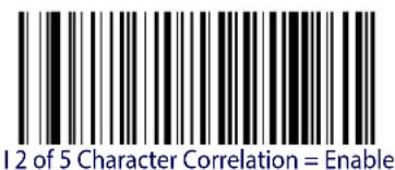
China Postal Code Stitching
This option enables/disables stitching for China Postal Code labels. When parts of a China Postal Code barcode are presented to the reader with this feature enabled, the barcode parts will be assembled by the reader's software, and the data will be decoded if all barcode proofing requirements are met.

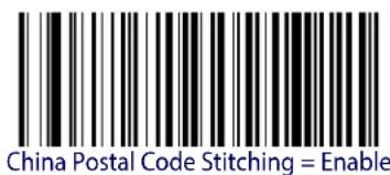

ENTER/EXIT PROGRAMMING MODE Codabar Enable/Disable
CODABAR
The following options apply to the Codabar symbology.
Codabar Enable/Disable
When disabled, the reader will not read Codabar barcodes.


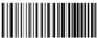
Codabar = Enable
Codabar = Disable
Codabar Check Character Calculation
Enable this option to enables/disables calculation and verification of an optional Codabar check character. When disabled, any check character in the label is treated as a data character


Codabar Check Character Calculation = Don't Calculate

Codabar Check Character Calculation = Enable AIM standard check char.
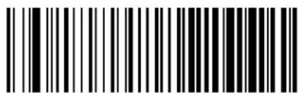
Codabar Check Character Calculation = Enable Modulo 10 check char.
Codabar Check Character Transmission
Enable this option to transmit the check character along with Codabar barcode data.
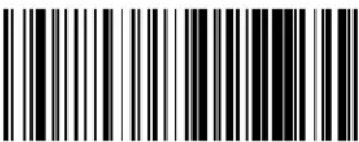 Codabar Check Character Transmission = Don’t Send Codabar Check Character Transmission = Don’t Send | |
 Codabar Check Character Transmission = Send Codabar Check Character Transmission = Send |  |
Codabar Start/Stop Character Transmission
Enable this option to enable/disable transmission of Codabar start and stop characters.
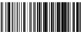 Codabar Start/Stop Character Transmission = Don’t Transmit Codabar Start/Stop Character Transmission = Don’t Transmit | |
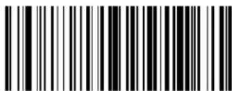 Codabar Start/Stop Character Transmission = Transmit Codabar Start/Stop Character Transmission = Transmit |  |

ENTER/EXIT PROGRAMMING MODE Codabar Start/Stop Character Set
Codabar Start/Stop Character Set
This option specifies the format of transmitted Codabar start/stop characters.
 Codabar Check Character Set = ABCD/TN*E Codabar Check Character Set = ABCD/TN*E | |
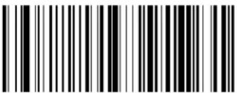 Codabar Check Character Set = ABCD/ABCD Codabar Check Character Set = ABCD/ABCD | |
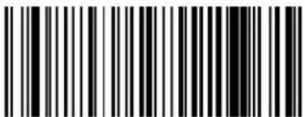 Codabar Check Character Set = abcd/tn*e Codabar Check Character Set = abcd/tn*e | |
 Codabar Check Character Set = abcd/abcd Codabar Check Character Set = abcd/abcd |  |
Codabar Start/Stop Character Match
When enabled, this option requires that start and stop characters match.
 |  Codabar Start/Stop Character Match = Don't Require Match Codabar Start/Stop Character Match = Don't Require Match |
 Codabar Start/Stop Character Match = Require Match Codabar Start/Stop Character Match = Require Match |
Codabar Quiet Zones
Specifies the number of quiet zones for Codabar labels. Quiet zones are blank areas at the ends of a barcode and are typically 10 times the width of the narrowest bar or space in the label.
 Codabar Quiet Zones = Quiet Zone on one side Codabar Quiet Zones = Quiet Zone on one side | |
 Codabar Quiet Zones = Quiet Zones on two sides Codabar Quiet Zones = Quiet Zones on two sides | |
 Codabar Quiet Zones = Auto Codabar Quiet Zones = Auto |  |
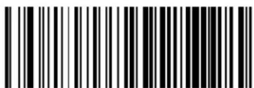 Codabar Quiet Zones = Virtual Quiet Zones on two sides Codabar Quiet Zones = Virtual Quiet Zones on two sides | |
 Codabar Quiet Zones = Small Quiet Zones on two sides Codabar Quiet Zones = Small Quiet Zones on two sides |

ENTER/EXIT PROGRAMMING MODE Codabar Minimum Reads
Codabar Minimum Reads
This feature specifies the minimum number of consecutive times a Codabar label must be decoded before it is accepted as good read.
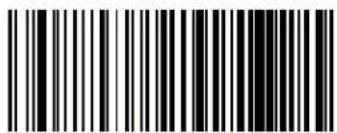 Codabar Minimum Reads = 1 Codabar Minimum Reads = 1 | |
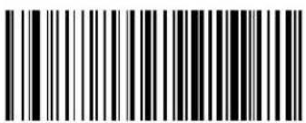 Codabar Minimum Reads = 2 Codabar Minimum Reads = 2 |  |
 Codabar Minimum Reads = 3 Codabar Minimum Reads = 3 | |
 Codabar Minimum Reads = 4 Codabar Minimum Reads = 4 |
Codabar Decoding Level
Decoding Levels are used to configure a barcode symbology decoder to be very aggressive to very conservative, depending on a particular customer's needs. See page 242 for more information on this feature.
 Codabar Decoding Level = 1 (Conservative) Codabar Decoding Level = 1 (Conservative) | |
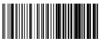 Codabar Decoding Level = 2 Codabar Decoding Level = 2 | |
 Codabar Decoding Level = 3 Codabar Decoding Level = 3 |  |
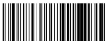 Codabar Decoding Level = 4 Codabar Decoding Level = 4 | |
 Codabar Decoding Level = 5 Codabar Decoding Level = 5 |
ENTER/EXIT PROGRAMMING MODE Codabar Length Control
Codabar Length Control
This feature specifies either variable length decoding or fixed length decoding for the Codabar symbology.
Variable Length. For variable length decoding, a minimum and maximum length may be set.
Fixed Length. For fixed length decoding, two different lengths may be set.


Codabar Set Length 1
This feature specifies one of the barcode lengths for Codabar Length Control. Length 1 is the minimum label length if in Variable Length Mode, or the first fixed length if in Fixed Length Mode. Length includes the barcode's start, stop, check and data characters. The length must include at least one data character. The length can be set from 3 to 50 characters.
Table 16 provides some examples for setting Length 1. See page 242 for detailed instructions on setting this feature.
Table 16. Codabar Length 1 Setting Examples
| STEP ACTION EXAMPLES | |||||
| 1 | Desired Setting (and pad with leading zeroes) | 03 Characters | 09 Characters | 15 Characters | 50 Characters |
| 2 Scan ENTER/EXIT PROGRAMMING MODE | |||||
| 3 Scan SELECT CODABAR LENGTH 1 SETTING | |||||
| 4 | Scan Two Characters From Appendix D, Keypad | ‘0’ and ‘3’ ‘0’ and ‘9’ ‘1’ and ‘5’ ‘5’ AND ‘0’ | |||
| 5 Scan ENTER/EXIT PROGRAMMING MODE | |||||

Select Codabar Length 1 Setting
Make a mistake? Scan the CANCEL barcode to abort and not save the entry string. You can then start again at the beginning.

CANCEL
DEFAULT
03 = Length 1 is 3 Characters
Codabar Set Length 2
This feature specifies one of the barcode lengths for Codabar Length Control. Length 2 is the maximum label length if in Variable Length Mode, or the second fixed length if in Fixed Length Mode. The length includes the barcode's start, stop, check and data characters. The length must include at least one data character.
The length can be set from 3 to 50 characters. A setting of 0 specifies to ignore this length (only one fixed length).
Table 17 provides examples for setting Length 2. See page 243 for detailed instructions on setting this feature.
Table 17. Codabar Length 2 Setting Examples
| STEP ACTION EXAMPLES | |||||
| 1 | Desired Setting (and pad with leading zeroes) | 00 Ignore This Length | 07 Characters 15 | Characters 50 Characters | |
| 2 Scan ENTER/EXIT PROGRAMMING MODE | |||||
| 3 Scan SELECT CODABAR LENGTH 2 SETTING | |||||
| 4 | Scan Two Characters From Appendix D, Keypad | ‘0’ and ‘0’ | ‘0’ and ‘7’ | ‘1’ and ‘5’ | ‘5’ AND ‘0’ |
| 5 Scan ENTER/EXIT PROGRAMMING MODE | |||||

Select Codabar Length 2 Setting
Make a mistake? Scan the CANCEL barcode to abort and not save the entry string. You can then start again at the beginning.
CANCEL
DEFAULT
50 = Length 2 is 50 Characters
Codabar Interdigit Ratio
This feature specifies the ratio between an intercharacter space and module for Codabar labels.
 Codabar Interdigit Ratio = Disable Codabar Interdigit Ratio = Disable | |
 Codabar Interdigit Ratio = 1 Codabar Interdigit Ratio = 1 | |
 Codabar Interdigit Ratio = 2 Codabar Interdigit Ratio = 2 | |
 Codabar Interdigit Ratio = 3 Codabar Interdigit Ratio = 3 | |
 |  Codabar Interdigit Ratio = 4 Codabar Interdigit Ratio = 4 |
 Codabar Interdigit Ratio = 5 Codabar Interdigit Ratio = 5 |

ENTER/EXIT PROGRAMMING MODE Codabar Interdigit Ratio
Codabar Interdigit Ratio (continued)
 Codabar Interdigit Ratio = 6 Codabar Interdigit Ratio = 6 | |
 Codabar Interdigit Ratio = 7 Codabar Interdigit Ratio = 7 | |
 Codabar Interdigit Ratio = 8 Codabar Interdigit Ratio = 8 | |
 Codabar Interdigit Ratio = 9 Codabar Interdigit Ratio = 9 | |
 Codabar Interdigit Ratio = 10 Codabar Interdigit Ratio = 10 |
Codabar Character Correlation
When correlation is enabled, the barcode reader will combine label data from multiple scans when decoding. Enabling correlation will help the scanner read labels that have some spots and/or voids. It may also help read labels that have damaged areas. Enabling correlation will also increase the chances that a label will be read incorrectly.


Codabar Character Correlation = Disable
Codabar Character Correlation = Enable
Codabar Stitching
This option enables/disables stitching for Codabar labels. When parts of a Codabar barcode are presented to the reader with this feature enabled, the barcode parts will be assembled by the reader's software, and the data will be decoded if all barcode proofing requirements are met.
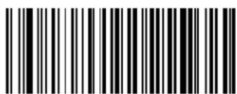
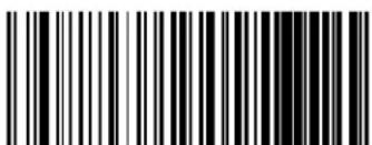
Codabar Stitching = Disable
Codabar Stitching = Enable

ENTER/EXIT PROGRAMMING MODE ABC Codabar Enable/Disable
ABC CODABAR
The following options apply to the ABC Codabar symbology.
ABC Codabar Enable/Disable
Enables/Disables ability of reader to decode ABC Codabar labels.


ABC Codabar = Enable
ABC Codabar = Disable
ABC Codabar Concatenation Mode
Specifies the concatenation mode between Static and Dynamic.

ABC Codabar Concatenation Mode = Static
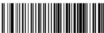
ABC Codabar Concatenation Mode = Dynamic
ABC Codabar Dynamic Concatenation Timeout
Specifies the timeout in 10-millisecond ticks used by the ABC Codabar Dynamic Concatenation Mode.
 ABC Codabar Dynamic Concatenation Timeout = 50 msec ABC Codabar Dynamic Concatenation Timeout = 50 msec | |
 ABC Codabar Dynamic Concatenation Timeout = 100 msec ABC Codabar Dynamic Concatenation Timeout = 100 msec | |
 |  ABC Codabar Dynamic Concatenation Timeout = 200 msec ABC Codabar Dynamic Concatenation Timeout = 200 msec |
 ABC Codabar Dynamic Concatenation Timeout = 500 msec ABC Codabar Dynamic Concatenation Timeout = 500 msec | |
 ABC Codabar Dynamic Concatenation Timeout = 750 msec ABC Codabar Dynamic Concatenation Timeout = 750 msec | |
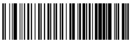 ABC Codabar Dynamic Concatenation Timeout = 1 Second ABC Codabar Dynamic Concatenation Timeout = 1 Second |

ENTER/EXIT PROGRAMMING MODE ABC Codabar Force Concatenation
ABC Codabar Force Concatenation
Forces labels starting or ending with D to be concatenated.
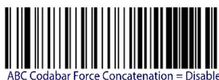

CODE 11
The following options apply to the Code 11 symbology.
Code 11 Enable/Disable
When disabled, the reader will not read Code 11 barcodes.


Code 11 = Enable
Code 11 = Disable
Code 11 Check Character Calculation
This option enables/disables calculation and verification of optional Code 11 check character.
 Code 11 Check Character Calculation = Disable Code 11 Check Character Calculation = Disable | |
 Code 11 Check Character Calculation = Check C Code 11 Check Character Calculation = Check C | |
 Code 11 Check Character Calculation = Check K Code 11 Check Character Calculation = Check K | |
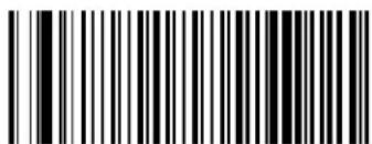 Code 11 Check Character Calculation = Check C and K Code 11 Check Character Calculation = Check C and K |  |
Code 11 Check Character Transmission
This feature enables/disables transmission of an optional Code 11 check character.
 Code 11 Check Character Transmission = Don’t Send Code 11 Check Character Transmission = Don’t Send | |
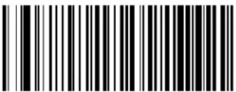 Code 11 Check Character Transmission = Send Code 11 Check Character Transmission = Send |  |
Code 11 Minimum Reads
This feature specifies the minimum number of consecutive times a Code 11 label must be decoded before it is accepted as good read.
 Code 11 Minimum Reads = 1 Code 11 Minimum Reads = 1 | |
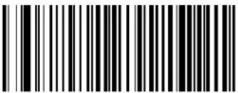 Code 11 Minimum Reads = 2 Code 11 Minimum Reads = 2 |  |
 Code 11 Minimum Reads = 3 Code 11 Minimum Reads = 3 | |
 Code 11 Minimum Reads = 4 Code 11 Minimum Reads = 4 |
Code 11 Length Control
This feature specifies either variable length decoding or fixed length decoding for the Code 11 symbology.
Variable Length. For variable length decoding, a minimum and maximum length may be set.
Fixed Length. For fixed length decoding, two different lengths may be set.

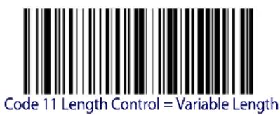

Code 11 Set Length 1
This feature specifies one of the barcode lengths for Code 11 Length Control. Length 1 is the minimum label length if in Variable Length Mode, or the first fixed length if in Fixed Length Mode. Length includes the barcode's check and data characters. The length can be set from 2 to 50 characters.
Table 18 provides some examples for setting Length 1. See page 242 for detailed instructions on setting this feature.
Table 18. Code 11 Length 1 Setting Examples
| STEP ACTION EXAMPLES | |||||
| 1 | Desired Setting (pad with leading zeroes) | 02 Characters 07 | Characters 15 Characters | 50 Characters | |
| 2 Scan ENTER/EXIT PROGRAMMING MODE | |||||
| 3 Scan SELECT CODE 11 LENGTH 1 SETTING | |||||
| 4 | Scan Two Characters From Appendix D, Keypad | ‘0’ and ‘2’ ‘0’ and ‘7’ ‘1’ and ‘5’ ‘5’ AND ‘0’ | |||
| 5 Scan ENTER/EXIT PROGRAMMING MODE | |||||

Select Code 11 Set Length 1 Setting
Make a mistake? Scan the CANCEL barcode to abort and not save the entry string. You can then start again at the beginning.

CANCEL
DEFAULT
04 = Length 1 is 4 Characters
Code 11 Set Length 2
This feature specifies one of the barcode lengths for Code 11 Length Control. Length 2 is the maximum label length if in Variable Length Mode, or the second fixed length if in Fixed Length Mode. Length includes the barcode's check and data characters.
The length can be set from 2 to 50 characters. A setting of 0 specifies to ignore this length (only one fixed length).
Table 19 provides examples for setting Length 2. See page 243 for detailed instructions on setting this feature.
Table 19. Code 11 Length 2 Setting Examples
| STEP ACTION EXAMPLES | |||||
| 1 | Desired Setting (pad with leading zeroes) | 00 (Ignore This Length) | 07 Characters 15 | Characters 50 Characters | |
| 2 Scan ENTER/EXIT PROGRAMMING MODE | |||||
| 3 Scan SELECT CODE 11 LENGTH 2 SETTING | |||||
| 4 | Scan Two Characters From Appendix D, Keypad | ‘0’ and ‘0’ | ‘0’ and ‘7’ | ‘0’ and ‘F’ | ‘3’ AND 2’ |
| 5 Scan ENTER/EXIT PROGRAMMING MODE | |||||

Select Code 11 Length 2 Setting
Make a mistake? Scan the CANCEL barcode to abort and not save the entry string. You can then start again at the beginning.

CANCEL
DEFAULT
50 = Length 2 is 50 Characters

ENTER/EXIT PROGRAMMING MODE Code 11 Interdigit Ratio
Code 11 Interdigit Ratio
This feature specifies the ratio between an intercharacter space and module for Code 11 labels.
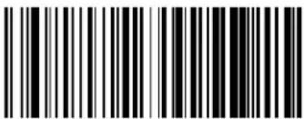 Code 11 Interdigit Ratio = Disable Code 11 Interdigit Ratio = Disable | |
 Code 11 Interdigit Ratio = 1 Code 11 Interdigit Ratio = 1 | |
 Code 11 Interdigit Ratio = 2 Code 11 Interdigit Ratio = 2 | |
 Code11 Interdigit Ratio = 3 Code11 Interdigit Ratio = 3 | |
 |  Code 11 Interdigit Ratio = 4 Code 11 Interdigit Ratio = 4 |
 Code 11 Interdigit Ratio = 5 Code 11 Interdigit Ratio = 5 |
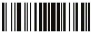
Code 11 ENTER/EXIT PROGRAMMING MODE
Code 11 Interdigit Ratio (continued)
 Code 11 Interdigit Ratio = 6 Code 11 Interdigit Ratio = 6 | |
 Code 11 Interdigit Ratio = 7 Code 11 Interdigit Ratio = 7 | |
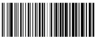 Code 11 Interdigit Ratio = 8 Code 11 Interdigit Ratio = 8 | |
 Code 11 Interdigit Ratio = 9 Code 11 Interdigit Ratio = 9 | |
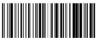 Code 11 Interdigit Ratio = 10 Code 11 Interdigit Ratio = 10 |

ENTER/EXIT PROGRAMMING MODE Code 11 Decoding Level
Code 11 Decoding Level
Decoding Levels are used to configure a barcode symbology decoder to be very aggressive to very conservative depending on a particular customer's needs. See page 242 for more information on this feature.
 Codabar Decoding Level = 1 (Conservative) Codabar Decoding Level = 1 (Conservative) | |
 Codabar Decoding Level = 2 Codabar Decoding Level = 2 | |
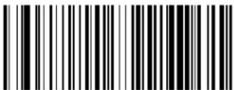 Codabar Decoding Level = 3 Codabar Decoding Level = 3 |  |
 Codabar Decoding Level = 4 Codabar Decoding Level = 4 | |
 Codabar Decoding Level = 5 (Aggressive) Codabar Decoding Level = 5 (Aggressive) |
Code 11 Character Correlation
When correlation is enabled, the barcode reader will combine label data from multiple scans when decoding. Enabling correlation will help the scanner read labels that have some spots and/or voids. It may also help read labels that have damaged areas. Enabling correlation will also increase the chances that a label will be read incorrectly.

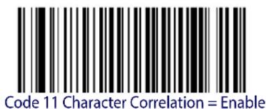
Code 11 Character Correlation = Disable
Code 11 Stitching
This option enables/disables stitching for Code 11 labels. When parts of a Code 11 barcode are presented to the reader with this feature enabled, the barcode parts will be assembled by the reader's software, and the data will be decoded if all barcode proofing requirements are met.

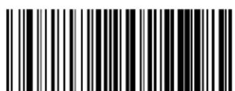

Code 11 Stitching = Disable
Code 11 Stitching = Enable
GS1 DATABAR™ OMNIDIRECTIONAL
The following options apply to the GS1 DataBar ^TM Omnidirectional (formerly RSS-14) symbology.
GS1 DataBar™ Omnidirectional Enable/Disable
When disabled, the reader will not read GS1 DataBar ^TM Omnidirectional barcodes.


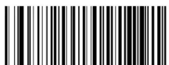
GS1 DataBar™ Omnidirectional = Enable
GS1 DataBar™ Omnidirectional GS1-128 Emulation
When enabled, GS1 DataBar ^TM Omnidirectional barcodes will be translated to the GS1-128 label data format.

GS1 DataBar™ Omnidirectional GS1-128 Emulation = Disable

GS1 DataBar™ Omnidirectional GS1-128 Emulation = Enable
GS1 DataBar™ Omnidirectional Minimum Reads
This feature specifies the minimum number of consecutive times a GS1 DataBar ^TM
Omnidirectional label must be decoded before it is accepted as good read.
 |  GS1 DataBarTM Omnidirectional Minimum Reads = 1 GS1 DataBarTM Omnidirectional Minimum Reads = 1 |
 GS1 DataBarTM Omnidirectional Minimum Reads = 2 GS1 DataBarTM Omnidirectional Minimum Reads = 2 | |
 GS1 DataBarTM Omnidirectional Minimum Reads = 3 GS1 DataBarTM Omnidirectional Minimum Reads = 3 | |
 GS1 DataBarTM Omnidirectional Minimum Reads = 4 GS1 DataBarTM Omnidirectional Minimum Reads = 4 |
GS1 DATABAR™ EXPANDED
The following options apply to the GS1 DataBar ^TM Expanded (formerly RSS Expanded) symbology.
GS1 DataBar™ Expanded Enable/Disable
When disabled, the reader will not read GS1 DataBar ^TM Expanded barcodes.


GS1 DataBar™ Expanded GS1-128 Emulation
When enabled, GS1 DataBar ^™ Expanded barcodes will be translated to the GS1-128 label data format.


GS1 DataBar™ Expanded Minimum Reads
This feature specifies the minimum number of consecutive times a GS1 DataBar ^™ Expanded label must be decoded before it is accepted as good read.
 |  GS1 DataBarTM Expanded Minimum Reads = 1 GS1 DataBarTM Expanded Minimum Reads = 1 |
 GS1 DataBarTM Expanded Minimum Reads = 2 GS1 DataBarTM Expanded Minimum Reads = 2 | |
 GS1 DataBarTM Expanded Minimum Reads = 3 GS1 DataBarTM Expanded Minimum Reads = 3 | |
 GS1 DataBarTM Expanded Minimum Reads = 4 GS1 DataBarTM Expanded Minimum Reads = 4 |
GS1 DataBar™ Expanded Length Control
This feature specifies either variable length decoding or fixed length decoding for the GS1 DataBar ^TM Expanded symbology.
Variable Length. For variable-length decoding, a minimum length may be set.
Fixed Length. For fixed-length decoding, two different lengths may be set.

GS1 DataBar™ Expanded Length Control = Fixed Length
GS1 DataBar™ Expanded Set Length 1
This feature specifies one of the barcode lengths for GS1 DataBar™ Expanded Length Control. Length 1 is the minimum label length if in Variable Length Mode, or the first fixed length if in Fixed Length Mode. Length includes the barcode's data characters only. The length can be set from 1 to 74 characters.
Table 20 provides some examples for setting Length 1. See page 242 for detailed instructions on setting this feature.
Table 20. GS1 DataBar™ Expanded Length 1 Setting Examples
| STEP ACTION EXAMPLES | ||||
| 1 Desired Setting | 01 Character | 07 Characters | 52 Characters | 74 Characters |
| 2 Scan ENTER/EXIT PROGRAMMING MODE | ||||
| 3 Scan SELECT GS1 DataBarTM EXPANDED LENGTH 1SETTING | ||||
| 4 | Scan Two Characters From Appendix D, Keypad | ‘0’ and ‘1’ | ‘0’ and ‘7’ | ‘5’ and ‘2’ |
| 5 Scan ENTER/EXIT PROGRAMMING MODE | ||||

Select GS1 DataBar™ Expanded Set Length 1 Setting
Make a mistake? Scan the CANCEL barcode to abort and not save the entry string. You can then start again at the beginning.

DEFAULT
01 = Length 1 is 1 Character
GS1 DataBar™ Expanded Set Length 2
This feature specifies one of the barcode lengths for GS1 DataBar™ Expanded Length Control. Length 2 is the maximum label length if in Variable Length Mode, or the second fixed length if in Fixed Length Mode. Length includes the barcode's data characters only. The length can be set from 1 to 74 characters. A setting of 0 specifies to ignore this length (only one fixed length).
Table 21 provides examples for setting Length 2. See page 243 for detailed instructions on setting this feature.
Table 21. GS1 DataBar™ Expanded Length 2 Setting Examples
| STEP ACTION EXAMPLES | ||||
| 1 Desired Setting | 00 (ignore second length) | 07 Characters 52 | Characters 74 Characters | Characters |
| 2 Scan ENTER/EXIT PROGRAMMING MODE | ||||
| 3 Scan SELECT GS1 DataBarTM EXPANDED LENGTH 2 SETTING | ||||
| 4 | Scan Two Characters From Appendix D, Keypad | ‘0’ and ‘0’ | ‘0’ and ‘7’ | ‘5’ and ‘2’ |
| 5 Scan ENTER/EXIT PROGRAMMING MODE | ||||

Select GS1 DataBar™ Expanded Set Length 2 Setting
Make a mistake? Scan the CANCEL barcode to abort and not save the entry string. You can then start again at the beginning.

CANCEL
DEFAULT
74 = Length 2 is 74 Characters

ENTER/EXIT PROGRAMMING MODE GS1 DataBar™ Limited Enable/Disable
GS1 DATABAR™ LIMITED
The following options apply to the GS1 DataBar ^™ Limited (formerly RSS Limited) symbology.
GS1 DataBar™ Limited Enable/Disable
When disabled, the reader will not read GS1 DataBar ^TM Limited barcodes.

GS1 DataBar™ Limited GS1-128 Emulation
When enabled, GS1 DataBar ^™ Limited barcodes will be translated to the GS1-128 label data format.


GS1 DataBar™ Limited Minimum Reads
This feature specifies the minimum number of consecutive times a GS1 DataBar ^™ Limited label must be decoded before it is accepted as good read.
 |  GS1 DataBarTM Limited Minimum Reads = 1 GS1 DataBarTM Limited Minimum Reads = 1 |
 GS1 DataBarTM Limited Minimum Reads = 2 GS1 DataBarTM Limited Minimum Reads = 2 | |
 GS1 DataBarTM Limited Minimum Reads = 3 GS1 DataBarTM Limited Minimum Reads = 3 | |
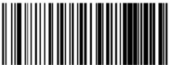 GS1 DataBarTM Limited Minimum Reads = 4 GS1 DataBarTM Limited Minimum Reads = 4 |

ENTER/EXIT PROGRAMMING MODE Code 93 Enable/Disable
CODE 93
The following options apply to the Code 93 symbology.
Enables/Disables ability of reader to decode Code 93 labels.


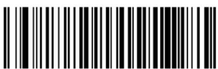
Code 93 = Enable
Code 93 = Disable
Code 93 Check Character Calculation
Enables/disables calculation and verification of an optional Code 93 check character.
 Code 93 Check Character Calculation = Disable Code 93 Check Character Calculation = Disable | |
 Code 93 Check Character Calculation = Enable Check C Code 93 Check Character Calculation = Enable Check C | |
 Code 93 Check Character Calculation = Enable Check K Code 93 Check Character Calculation = Enable Check K | |
 Code 93 Check Character Calculation = Enable Check C and K Code 93 Check Character Calculation = Enable Check C and K |  |
Code 93 Check Character Transmission
Enables/disables transmission of an optional Code 93 check character.

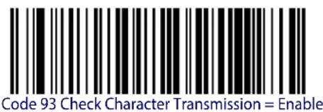
Code 93 Length Control
This feature specifies either variable length decoding or fixed length decoding for the Code 93 symbology.
Variable Length. For variable length decoding, a minimum and maximum length may be set.
Fixed Length. For fixed length decoding, two different lengths may be set.


Code 93 Set Length 1
Specifies one of the barcode lengths for Code 93 Length Control. Length 1 is the minimum label length if in Variable Length Mode, or the first fixed length if in Fixed Length Mode. Length includes the barcode's data characters only. The length can be set from 01 to 50 characters.
Table 22 provides some examples for setting Length 1. See page 242 for detailed instructions on setting this feature.
Table 22. Code 93 Length 1 Setting Examples
| STEP ACTION EXAMPLES | ||||
| 1 Desired Setting | 01 Characters 07 | Characters 15 Characters | 50 Characters | |
| 2 Scan ENTER/EXIT PROGRAMMING MODE | ||||
| 3 Scan SELECT CODE 93 LENGTH 1 SETTING | ||||
| 4 | Scan Two Characters FromAppendix D, Keypad | ‘0’ and ‘1’ | ‘0’ and ‘7’ | ‘1’ and ‘5’ |
| 5 Scan ENTER/EXIT PROGRAMMING MODE | ||||
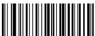
Select Code 93 Set Length 1 Setting
Make a mistake? Scan the CANCEL barcode to abort and not save the entry string. You can then start again at the beginning.

CANCEL
DEFAULT
01 = Length 1 is 1 Character
Code 93 Set Length 2
This feature specifies one of the barcode lengths for Code 93 Length Control. Length 2 is the maximum label length if in Variable Length Mode, or the second fixed length if in Fixed Length Mode. Length includes the barcode's check, data, and full-ASCII shift characters. The length does not include start/stop characters. The length can be set from 1 to 50 characters. A setting of 0 specifies to ignore this length (only one fixed length).
Table 23 provides examples for setting Length 2. See page 243 for detailed instructions on setting this feature.
Table 23. CODE 93 Length 2 Setting Examples
| STEP ACTION EXAMPLES | ||||
| 1 Desired Setting | 00 (Ignore This Length) | 07 Characters 15 | Characters 50 Characters | Characters |
| 2 Scan ENTER/EXIT PROGRAMMING MODE | ||||
| 3 Scan SELECT CODE 93 LENGTH 2 SETTING | ||||
| 4 | Scan Two Characters From Appendix D, Keypad | ‘0’ and ‘0’ | ‘0’ and ‘7’ | ‘1’ and ‘5’ |
| 5 Scan ENTER/EXIT PROGRAMMING MODE | ||||

Select Code 93 Length 2 Setting

CANCEL
DEFAULT
50 = Length 2 is 50 Characters

ENTER/EXIT PROGRAMMING MODE Code 93 Minimum Reads
Code 93 Minimum Reads
This feature specifies the minimum number of consecutive times a Code 93 label must be decoded before it is accepted as good read.
 | 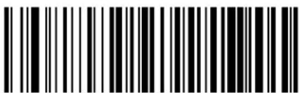 Code 93 Minimum Reads = 1 Code 93 Minimum Reads = 1 |
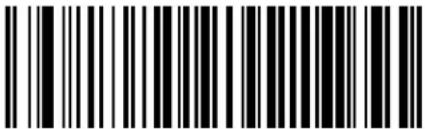 Code 93 Minimum Reads = 2 Code 93 Minimum Reads = 2 | |
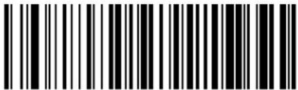 Code 93 Minimum Reads = 3 Code 93 Minimum Reads = 3 | |
 Code 93 Minimum Reads = 4 Code 93 Minimum Reads = 4 |
Code 93 Decoding Level
Specifies the decoding level for Code 93. Decoding Levels are used to configure a barcode symbology decoder to be very aggressive to very conservative depending on a particular customer's needs. See page 242 for more information on this feature.
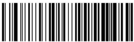 Code 93 Decoding Level = Disable Code 93 Decoding Level = Disable | |
 Code 93 Decoding Level = 1 (Conservative) Code 93 Decoding Level = 1 (Conservative) | |
 Code 93 Decoding Level = 2 Code 93 Decoding Level = 2 | |
 Code 93 Decoding Level = 3 Code 93 Decoding Level = 3 |  |
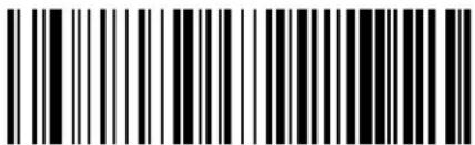 Code 93 Decoding Level = 4 Code 93 Decoding Level = 4 | |
 Code 93 Decoding Level = 5 (Aggressive) Code 93 Decoding Level = 5 (Aggressive) |

ENTER/EXIT PROGRAMMING MODE Code 93 Quiet Zones
Code 93 Quiet Zones
Enables/disables quiet zones for Code 93.
 Code 93 Quiet Zones = No Quiet Zones Code 93 Quiet Zones = No Quiet Zones | |
 Code 93 Quiet Zones = Quiet Zone on one side Code 93 Quiet Zones = Quiet Zone on one side | |
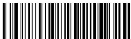 Code 93 Quiet Zones = Quiet Zones on two sides Code 93 Quiet Zones = Quiet Zones on two sides | |
 Code 93 Quiet Zones = Auto Code 93 Quiet Zones = Auto |  |
 Code 93 Quiet Zones = Virtual Quiet Zones on two sides Code 93 Quiet Zones = Virtual Quiet Zones on two sides |
Code 93 Stitching
Disable/enable fixed or variable length stitching for Code 93.
 Code 93 Stitching = Disable Code 93 Stitching = Disable | |
 Code 93 Stitching = Enable Code 93 Stitching = Enable |  |
Code 93 Character Correlation
Enables/disables Character Correlation for Code 93.
 |  Code 93 Character Correlation = Disable Code 93 Character Correlation = Disable |
 Code 93 Character Correlation = Enable Code 93 Character Correlation = Enable |

ENTER/EXIT PROGRAMMING MODE MSI Enable/Disable
MSI
The following options apply to the MSI symbology.
MSI Enable/Disable
Enables/Disables ability of reader to decode MSI labels.


MSI Check Character Calculation
Enables/Disables calculation and verification of an optional MSI check character.
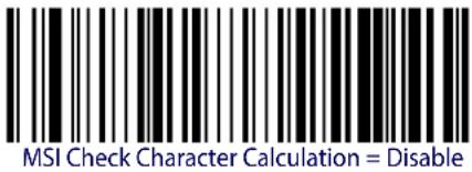 | |
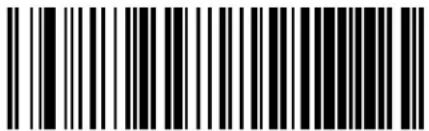 MSI Check Character Calculation = Enable Mod10 MSI Check Character Calculation = Enable Mod10 |  |
 MSI Check Character Calculation = Enable Mod11/10 MSI Check Character Calculation = Enable Mod11/10 | |
 MSI Check Character Calculation = Enable Mod10/10 MSI Check Character Calculation = Enable Mod10/10 |
MSI Check Character Transmission
Enables/disables transmission of an MSI check character.
 MSI Check Character Transmission = Disable MSI Check Character Transmission = Disable | |
 MSI Check Character Transmission = Enable MSI Check Character Transmission = Enable |  |
MSI Length Control
This feature specifies either variable length decoding or fixed length decoding for the MSI symbology.
Variable Length. For variable length decoding, a minimum and maximum length may be set.
Fixed Length. For fixed length decoding, two different lengths may be set.
 |  MSI Length Control = Variable Length MSI Length Control = Variable Length |
 MSI = Fixed Length MSI = Fixed Length |
MSI Set Length 1
This feature specifies one of the barcode lengths for MSI Length Control. Length 1 is the minimum label length if in Variable Length Mode, or the first fixed length if in Fixed Length Mode. Length includes the barcode's data characters only. The length can be set from 01 to 50 characters.
Table 24 provides some examples for setting Length 1. See page 242 for detailed instructions on setting this feature.
Table 24. MSI Length 1 Setting Examples
| STEP ACTION EXAMPLES | ||||
| 1 Desired Setting | 01 Characters 07 | Characters 15 Characters | 50 Characters | |
| 2 Scan ENTER/EXIT PROGRAMMING MODE | ||||
| 3 Scan SELECT MSI LENGTH 1 SETTING | ||||
| 4 | Scan Two Characters From Appendix D, Keypad | '0' and '1' | '0' and '7' | '1' and '5' |
| 5 Scan ENTER/EXIT PROGRAMMING MODE | ||||

Select MSI Set Length 1 Setting
Make a mistake? Scan the CANCEL barcode to abort and not save the entry string. You can then start again at the beginning.

CANCEL
DEFAULT
01 = Length 1 is 1 Character
MSI Set Length 2
This feature specifies one of the barcode lengths for MSI Length Control. Length 2 is the maximum label length if in Variable Length Mode, or the second fixed length if in Fixed Length Mode. Length includes the barcode's check, data, and full-ASCII shift characters. The length does not include start/stop characters.
The length can be set from 1 to 50 characters. A setting of 0 specifies to ignore this length (only one fixed length).
Table 25 provides examples for setting Length 2. See page 243 for detailed instructions on setting this feature.
Table 25. MSI Length 2 Setting Examples
| STEP ACTION EXAMPLES | ||||
| 1 Desired Setting | 00 (Ignore This Length) | 07 Characters 15 | Characters 50 Characters | Characters |
| 2 Scan ENTER/EXIT PROGRAMMING MODE | ||||
| 3 Scan SELECT MSI LENGTH 2 SETTING | ||||
| 4 | Scan Two Characters From Appendix D, Keypad | ‘0’ and ‘0’ | ‘0’ and ‘7’ | ‘1’ and ‘5’ |
| 5 Scan ENTER/EXIT PROGRAMMING MODE | ||||

Select MSI Length 2 Setting
Make a mistake? Scan the CANCEL barcode to abort and not save the entry string. You can then start again at the beginning.
CANCEL
DEFAULT
50 = Length 2 is 50 Characters

ENTER/EXIT PROGRAMMING MODE MSI Minimum Reads
MSI Minimum Reads
This feature specifies the minimum number of consecutive times an MSI label must be decoded before it is accepted as good read.
 MSI Minimum Reads = 1 MSI Minimum Reads = 1 | |
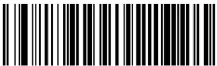 MSI Minimum Reads = 2 MSI Minimum Reads = 2 | |
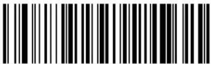 MSI Minimum Reads = 3 MSI Minimum Reads = 3 | |
 MSI Minimum Reads = 4 MSI Minimum Reads = 4 |  |
MSI Decoding Level
Specifies the decoding level for MSI. Decoding Levels are used to configure a barcode symbology decoder to be very aggressive to very conservative depending on a particular customer's needs. See page 242 for more information on this feature.
 MSI Decoding Level = Disable MSI Decoding Level = Disable | |
 MSI Decoding Level = 1 (conservative) MSI Decoding Level = 1 (conservative) | |
 MSI Decoding Level = 2 MSI Decoding Level = 2 | |
 MSI Decoding Level = 3 MSI Decoding Level = 3 |  |
 MSI Decoding Level = 4 MSI Decoding Level = 4 | |
 MSI Decoding Level = 5 (aggressive) MSI Decoding Level = 5 (aggressive) |
ENTER/EXIT PROGRAMMING MODE Plessey Enable/Disable
PLESSEY
The following options apply to the Plessey symbology.
Plessey Enable/Disable
Enables/Disables ability of reader to decode Plessey labels.

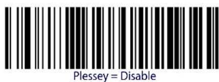

Plessey Check Character Calculation
Enables/Disables calculation and verification of an optional Plessey check character.
 Plessey Check Character Calculation = Disable Plessey Check Character Calculation = Disable | |
 Plessey Check Character Calculation = Enable Plessey std. check char. verification Plessey Check Character Calculation = Enable Plessey std. check char. verification |  |
 Plessey Check Character Calculation = Enable Anker check char. verification Plessey Check Character Calculation = Enable Anker check char. verification | |
 Plessey Check Character Calculation = Enable Plessey std. and Anker check char verification Plessey Check Character Calculation = Enable Plessey std. and Anker check char verification |
Plessey Check Character Transmission
Enables/disables transmission of an MSI check character.
 Plessey Check Character Transmission = Disable Plessey Check Character Transmission = Disable | |
 Plessey Check Character Transmission = Enable Plessey Check Character Transmission = Enable |  |

ENTER/EXIT PROGRAMMING MODE Plessey Length Control
Plessey Length Control
This feature specifies either variable length decoding or fixed length decoding for the Plessey symbology.
Variable Length. For variable length decoding, a minimum and maximum length may be set.
Fixed Length. For fixed length decoding, two different lengths may be set.


Plessey Length Control = Variable Length

Plessey = Fixed Length
Plessey Set Length 1
This feature specifies one of the barcode lengths for Plessey Length Control. Length 1 is the minimum label length if in Variable Length Mode, or the first fixed length if in Fixed Length Mode. Length includes the barcode's data characters only. The length can be set from 01 to 50 characters.
Table 26 provides some examples for setting Length 1. See page 242 for detailed instructions on setting this feature.
Table 26. Plessey Length 1 Setting Examples
| STEP ACTION EXAMPLES | ||||
| 1 Desired Setting | 01 Characters | 07 Characters | 15 Characters | 50 Characters |
| 2 Scan ENTER/EXIT PROGRAMMING MODE | ||||
| 3 Scan SELECT Plessey LENGTH 1 SETTING | ||||
| 4 | Scan Two Characters From Appendix D, Keypad | ‘0’ and ‘1’ | ‘0’ and ‘7’ | ‘1’ and ‘5’ |
| 5 Scan ENTER/EXIT PROGRAMMING MODE | ||||
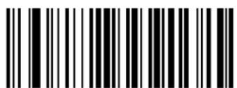
Select Plessey Set Length 1 Setting
Make a mistake? Scan the CANCEL barcode to abort and not save the entry string. You can then start again at the beginning.

CANCEL
DEFAULT
01 = Length 1 is 1 Character
Plessey Set Length 2
This feature specifies one of the barcode lengths for Plessey Length Control. Length 2 is the maximum label length if in Variable Length Mode, or the second fixed length if in Fixed Length Mode. Length includes the barcode's check, data, and full-ASCII shift characters. The length does not include start/stop characters.
The length can be set from 1 to 50 characters. A setting of 0 specifies to ignore this length (only one fixed length).
Table 27 provides examples for setting Length 2. See page 243 for detailed instructions on setting this feature.
Table 27. Plessey Length 2 Setting Examples
| STEP ACTION EXAMPLES | |||||
| 1 Desired Setting | 00 (Ignore This Length) | 07 Characters 15 | Characters 50 Characters | ||
| 2 Scan ENTER/EXIT PROGRAMMING MODE | |||||
| 3 Scan SELECT PLESSEY LENGTH 2 SETTING | |||||
| 4 | Scan Two Characters From Appendix D, Keypad | ‘0’ and ‘0’ | ‘0’ and ‘7’ | ‘1’ and ‘5’ | ‘5’ AND ‘0’ |
| 5 Scan ENTER/EXIT PROGRAMMING MODE | |||||

Select Plessey Length 2 Setting
Make a mistake? Scan the CANCEL barcode to abort and not save the entry string. You can then start again at the beginning.
CANCEL
DEFAULT
50 = Length 2 is 50 Characters
Plessey Minimum Reads
This feature specifies the minimum number of consecutive times a Plessey label must be decoded before it is accepted as good read.
 Plessey Minimum Reads = 1 Plessey Minimum Reads = 1 | |
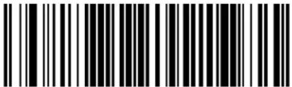 Plessey Minimum Reads = 2 Plessey Minimum Reads = 2 | |
 Plessey Minimum Reads = 3 Plessey Minimum Reads = 3 | |
 Plessey Minimum Reads = 4 Plessey Minimum Reads = 4 |  |

ENTER/EXIT PROGRAMMING MODE Plessey Decoding Level
Plessey Decoding Level
Specifies the decoding level for Plessey. Decoding Levels are used to configure a barcode symbology decoder to be very aggressive to very conservative depending on a particular customer's needs. See page 242 for more information on this feature.
 Plessey Decoding Level = Disable Plessey Decoding Level = Disable | |
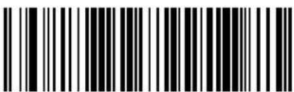 Plessey Decoding Level = 1 (conservative) Plessey Decoding Level = 1 (conservative) | |
 Plessey Decoding Level = 2 Plessey Decoding Level = 2 | |
 Plessey Decoding Level = 3 Plessey Decoding Level = 3 |  |
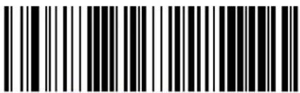 Plessey Decoding Level = 4 Plessey Decoding Level = 4 | |
 Plessey Decoding Level = 5 (aggressive) Plessey Decoding Level = 5 (aggressive) |
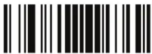
Plessey ENTER/EXIT PROGRAMMING MODE
Plessey Stitching
Enables/disables fixed length stitching for Plessey.

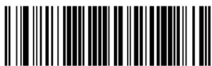
Plessey Stitching = Enable
Plessey Stitching = Disable
Plessey Character Correlation
Enables/disables Character Correlation for Plessey.

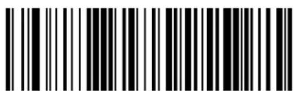
Plessey Character Correlation = Disable

Plessey Character Correlation = Enable

ENTER/EXIT PROGRAMMING MODE Code 4 Enable/Disable
CODE 4
The following options apply to the Code 4 symbology.
Enables/Disables ability of imager to decode Code 4 labels.


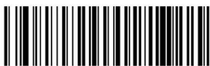
Code 4 = Enable
Code 4 = Disable
Code 4 Check Character Transmission
This feature enables/disables transmission of an optional Code 4 check character.

Code 4 Check Character Transmission = Send

Code 4 Check Character Transmission = Don't Send

Code 4 Hex to Decimal Conversion
This feature enables/disables the conversion of hexadecimal label data to decimal label data.
 Code 4 Hex to Decimal Conversion = Disable Code 4 Hex to Decimal Conversion = Disable | |
 Code 4 Hex to Decimal Conversion = Enable Code 4 Hex to Decimal Conversion = Enable |  |
CODE 5
The following options apply to the Code 5 symbology.
Enables/Disables ability of imager to decode Code 5 labels.
 |  Code 5 = Disable Code 5 = Disable |
 Code 5 = Enable Code 5 = Enable |
Code 5 Check Character Transmission
This feature enables/disables transmission of an optional Code 5 check character.
| Code 5 Check Character Transmission = Don't Send | |
 Code 5 Check Character Transmission = Send Code 5 Check Character Transmission = Send |  |
Code 5 Hex to Decimal Conversion
This feature enables/disables the conversion of hexadecimal label data to decimal label data.
| Code 5 Hex to Decimal Conversion = Disable | |
 Code 5 Hex to Decimal Conversion = Enable Code 5 Hex to Decimal Conversion = Enable |  |
CODE 4 AND CODE 5 COMMON CONFIGURATION ITEMS
The following options apply to both Code 4 and Code 5 symbologies.
Code 4 and 5 Decoding Level
Decoding Levels are used to configure a barcode symbology decoder to be very aggressive to very conservative depending on a particular customer's needs. See page 231 for more information on this feature.

This configuration item applies to Code 4 and Code 5.
 Code 4 and Code 5 Decoding Level = 1 (conservative) Code 4 and Code 5 Decoding Level = 1 (conservative) | |
 Code 4 and Code 5 Decoding Level = 2 Code 4 and Code 5 Decoding Level = 2 | |
 Code 4 and Code 5 Decoding Level = 3 Code 4 and Code 5 Decoding Level = 3 |  |
 Code 4 and Code 5 Decoding Level = 4 Code 4 and Code 5 Decoding Level = 4 | |
 Code 4 and Code 5 Decoding Level = 5 (aggressive) Code 4 and Code 5 Decoding Level = 5 (aggressive) |

ENTER/EXIT PROGRAMMING MODE Code 4 and Code 5 Minimum Reads
Code 4 and Code 5 Minimum Reads
This feature specifies the minimum number of consecutive times a Code 4 or Code 5 label must be decoded before it is accepted as good read.
 |  Code 4 or Code 5 Minimum Reads = 1 Code 4 or Code 5 Minimum Reads = 1 |
 Code 4 or Code 5 Minimum Reads = 2 Code 4 or Code 5 Minimum Reads = 2 | |
 Code 4 or Code 5 Minimum Reads = 3 Code 4 or Code 5 Minimum Reads = 3 | |
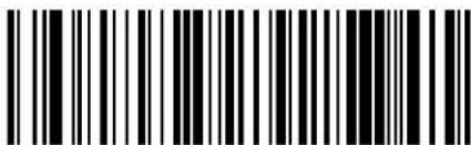 Code 4 or Code 5 Minimum Reads = 4 Code 4 or Code 5 Minimum Reads = 4 |
NOTES
LASER FEATURES
| LASER SCAN ANGLE on page 228 |
| LASER IDLE MODE on page 228 |
| BI-DIRECTIONAL READ DECODING on page 229 |
| ALWAYS ON SCAN MODE TIMEOUT on page 230 |
This section provides options and programming related to the reader's laser features. Reference Appendix B, Standard Defaults for a listing of standard factory settings.

For hands-free or stand operations, it is recommended that Flashing scan mode be used. See "Scan Mode" on page 73 for programming labels for this feature. For more information, go to page 254 in "References".
Laser Scan Angle
This feature sets the scan angle for the laser. The Narrow scan angle is helpful for selecting and reading a specific barcode among a tight grouping of labels.


Laser Idle Mode
Laser Idle Mode option is applicable for; trigger Single, Trigger Hold Multiple & Trigger Pulse Multiple only.
This configuration provides control over the laser scanning motor when the laser is not actively scanning. The options are:
Dither Disable. Shuts down the motor (laser mirror dithering) during laser engine idle time to reduce overall scanner power consumption.
Dither Enable. Allows the laser engine motor to continue dithering when laser is not active; may provide an improved read response time.



ENTER/EXIT PROGRAMMING MODE Bi-Directional Read Decoding
Bi-Directional Read Decoding
This configuration provides control over the good read and barcode label requirement. This programming option for Gyphon Laser affects all barcode symbologies.
Bi-Directional Read Disable. When Bi-directional reading is disabled, the laser scan is only required to obtain a valid label read in one scanning direction.
Bi-Directional Read Enable. When enabled, the reader is must obtain a valid good read in both scanning directions as part of the label read/decode process. Enabled will provides increased decode reliability.
 Bi-Directional Read Disable Bi-Directional Read Disable | |
 Bi-Directional Read Enable Bi-Directional Read Enable |  |
Always On Scan Mode Timeout
When the WLS9600 is in Always On scanning mode, timeout periods can be configured. If the programmed Always On Timeout elapses, the reader will shut down and a trigger pull is required to resume operation.
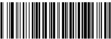 Always On Timeout: 1 Hour Always On Timeout: 1 Hour | |
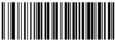 Always On Timeout: 2 Hours Always On Timeout: 2 Hours | |
 Always On Timeout: 3 Hours Always On Timeout: 3 Hours | |
 Always On Timeout: 4 Hours Always On Timeout: 4 Hours | |
 |  Always On Timeout: 5 Hours Always On Timeout: 5 Hours |
Chapter 5 References
This section contains explanations and examples of selected barcode features. See the Configuration section for the actual barcode labels used to configure the reader.
RS-232 Parameters
RS-232 Only
Baud Rate
Baud rate is the number of bits of data transmitted per second. Set the reader's baud rate to match the baud rate setting of the host device. With an improper baud rate setting, data may not reach the host correctly.
Stop Bits
The stop bit(s) at the end of each transmitted character marks the end of transmission of one character and prepares the receiving device for the next character in the serial data stream. The number of stop bits selected (one or two) depends on the number the receiving terminal is programmed to accommodate. Set the number of stop bits to match host device requirements.
Parity
This feature specifies parity required for sending and receiving data. A parity check bit is the most significant bit of each ASCII coded character. Select the parity type according to host device requirements.
- Select None when no parity bit is required.
- Select Odd parity and the parity bit value is set to 0 or 1, based on data, to ensure that an odd number of 1 bits are contained in the coded character.
- Select Even parity and the parity bit value is set to 0 or 1, based on data, to ensure that an even number of 1 bits are contained in the coded character.
Handshaking Control
The data interface consists of an RS-232 port designed to operate either with or without the hardware handshaking lines, Request to Send (RTS), and Clear to Send (CTS). Handshaking Control includes the following options:
- RTS — RTS is asserted during transmissions. CTS is ignored.
-
RTS/CTS — RTS is asserted during transmissions. CTS gates transmissions.
-
RTS/XON/XOFF — RTS is asserted during transmissions. CTS is ignored. XON and XOFF gate transmissions.
- RTS On/CTS — RTS is always asserted. CTS gates transmissions.
RTS/CTS Scan Control — RTS is asserted during transmissions. CTS gates transmissions and controls enable and disable state of scanner.
RS-232/USB COM Parameters
Intercharacter Delay
This parameter specifies the intercharacter delay between the end of one character and the beginning of the next. The delay can be set within a range of zero (0) to 990 milliseconds in 10ms increments. A setting of zero specifies no delay.
To set the delay:
- Determine the desired setting in milliseconds.
- Divide the desired setting by 10 (setting is in 10ms increments). Pad the result with leading zeroes to yield two digits. For example: 0 = 00, 5 = 05, 20 = 20, etc.
- Scan the ENTER/EXIT PROGRAMMING MODE barcode to enter Programming Mode.
- Go to page 25 and scan the barcode: SELECT INTERCHARACTER DELAY SETTING.
- Scan the appropriate two digits from the keypad in Appendix D, Keypad, that represent the duration which was determined in the steps above. You will hear a two-beep indication after the last character.

If you make a mistake before the last character, scan the CANCEL barcode to abort and not save the entry string. You can then start again at the beginning.
- Scan the ENTER/EXIT PROGRAMMING MODE barcode to exit.
This completes the procedure. See Table 28 for some examples of how to set this feature.
Table 28. Intercharacter Delay Setting Examples
| STEP ACTION EXAMPLES | |||||
| 1 Desired Setting | 50ms 150ms | 600ms 850ms | |||
| 2 | Divide by 10 (pad with leading zeroes to yield two-digits) | 05 15 60 85 | |||
| 3 | Scan ENTER/EXIT PROGRAMMING MODE | ||||
| 4 | Scan SELECT INTERCHARACTER DELAY SETTING | ||||
| 5 | Scan Two Characters From Appendix D, Keypad | ‘0’ and ‘5’ | ‘5’ and ‘0’ | ‘6’ and ‘0’ | ‘8’ and ‘5’ |
| 6 | Scan ENTER/EXIT PROGRAMMING MODE | ||||
ACK NAK Options
This enables/disables the ability of the reader to support the RS-232 ACK/NAK protocol. When configured, the reader and/or host sends an “ACK” when it receives data properly, and sends “NAK” when the data is in error.
Options are:
• D i s a b l e
- Enable for label transmission — The reader expects an ACK/NAK response from the host when a label is sent.
- Enable for host-command acknowledge — The reader will respond with ACK/NAK when the host sends a command.
- Enable for label transmission and host-command acknowledge
ACK Character
This setting specifies an ASCII character or hex value to be used as the ACK character. ASCII characters or any hex value from 0 to 0xFF can be selected.

Setting to previously defined characters such as XON, XOFF, or host mands conflicts with normal operation of these characters. 8-bit data is not recognized when the option Data Bitshas been set as 7 Data Bits.
- Determine the desired character or value.
- Use the ASCII Chart on the inside back cover of this manual to find the hex equivalent for the desired character/value.
- Go to page 28 and scan ENTER/EXIT PROGRAMMING MODE to enter Programming Mode.
- Scan the barcode: SELECT ACK CHARACTER SETTING.
- Scan the appropriate two alpha-numeric characters from the keypad in Appendix D, Keypad, that represent the desired character/value in step 1 above. The second character will cause a two-beep indication.
- Scan the ENTER/EXIT PROGRAMMING MODE barcode to exit.
See Table 29 for some examples of how to set this feature.
Table 29. ACK Character Setting Examples
| STEP ACTION EXAMPLES | |||||
| 1 | Desired Character/Value | ACK | $ | @ | > |
| 2 | Hex equivalent from ASCII Chart | 0x06 | 0x24 | 0x40 | 0x3E |
| 3 | Scan ENTER/EXIT PROGRAMMING MODE | ||||
| 4 | Scan SELECT ACK CHARACTER SETTING | ||||
| 5 | Scan Two Characters from Appendix D, Keypad | ‘0’ and ‘6’ | ‘2’ and ‘4’ | ‘4’ and ‘0’ | ‘3’ AND ‘E’ |
| 6 | Scan ENTER/EXIT PROGRAMMING MODE | ||||
NAK Character
This setting specifies an ASCII character or hex value to be used as the NAK character. ASCII characters or any hex value from 0 to 0xFF can be selected.

Setting to previously defined characters such as XON, XOFF, or host commands conflicts with normal operation of these characters. 8-bit data is not recognized when the option Data Bits has been set as 7 Data Bits.
To set this feature:
- Determine the desired character or value.
- Use the ASCII Chart on the inside back cover of this manual to find the hex equivalent for the desired character/value.
- Go to page 28 and scan the ENTER/EXIT PROGRAMMING MODE barcode to enter Programming Mode.
- Scan the barcode: SELECT NAK CHARACTER SETTING.
- Scan the appropriate two alpha-numeric characters from the keypad in Appendix D, Keypad, that represent the desired character/value in step 1 above. The second character will cause a two-beep indication.
- Scan the ENTER/EXIT PROGRAMMING MODE barcode to exit Programming Mode.
This completes the procedure. See Table 30 for some examples of how to set this feature.
Table 30. NAK Character Setting Examples
| STEP ACTION EXAMPLES | |||||
| 1 Desired Character/Value2 | Hex equivalent from ASCII Chart | NAK $ @ >0x15 0x24 0x40 0x3E | |||
| 3 Scan ENTER/EXIT PROGRAMMING MODE | |||||
| 4 | Scan SELECT ACK CHARACTER SETTING | ||||
| 5 | Scan Two Characters From Appendix D, Keypad | ‘1’ and ‘5’ | ‘2’ and ‘4’ | ‘4’ and ‘0’ | ‘3’ AND ‘E’ |
| 6 Scan ENTER/EXIT PROGRAMMING MODE | |||||
ACK NAK Timeout Value
This option specifies the amount of time the reader waits for an ACK character from the host following label transmission. The selectable timeout range is 200 milliseconds to 15,000ms (15 seconds) in 200ms increments. A selection of 0 disables the timeout.
To set this value:
- Determine the desired setting in milliseconds.
- Divide the desired setting by 200 (setting is in 200ms increments). Pad the result with leading zeroes to yield two digits. For example: 0 = 00 , 5 = 05 , 20 = 20 , etc.
- Go to page 29 and scan the ENTER/EXIT PROGRAMMING MODE barcode to enter Programming Mode.
- Scan the barcode: SELECT ACK NAK TIMEOUT VALUE SETTING.
- Scan the appropriate two digits from the keypad in Appendix D, Keypad, that represent the duration which was determined in the steps above. You will hear a two-beep indication after the last character.

If you make a mistake before the last character, scan the CANCEL barcode to abort and not save the entry string. You can then start again at the beginning.
- Scan the ENTER/EXIT PROGRAMMING MODE barcode to exit Programming Mode.
This completes the procedure. See Table 31 for some examples of how to set this feature.
Table 31. ACK NAK Timeout Value Setting Examples
| STEP ACTION EXAMPLES | |||||
| 1 Desired Setting | 200ms | 1,000ms (1 sec.) | 5200ms (5.2 sec.) | 15,000ms (15 sec.) | |
| 2 Divide by 200 | 01 05 26 | 75 | |||
| 3 | Scan ENTER/EXIT PROGRAMMING MODE | ||||
| 4 | Scan SELECT ACK NAK TIMEOUT VALUE SETTING | ||||
| 5 | Scan Two Characters FromAppendix D, Keypad | ‘0’ and ‘1’ | ‘0’ and ‘5’ | ‘2’ and ‘6’ | ‘7’ and ‘5’ |
| 6 | Scan ENTER/EXIT PROGRAMMING MODE | ||||
ACK NAK Retry Count
This feature specifies the number of times the reader retries a label transmission due to a retry condition. The selectable range is from 1 to 254 retries. A selection of 0 disables the count, and a selection of 255 specifies unlimited retries.
To set this feature:
- Determine the desired setting.
- Pad the number with leading zeroes to yield three digits. For example: 0 = 000, 5 = 005, 20 = 020, etc.
- Go to page 29 and scan the ENTER/EXIT PROGRAMMING MODE barcode to enter Programming Mode.
-
Scan the barcode: SELECT ACK NAK RETRY COUNT SETTING.
-
Scan the appropriate three digits from the keypad in Appendix D, Keypad, that represent the number which was determined in the steps above. You will hear a two-beep indication after the last character.

If you make a mistake before the last character, scan the CANCEL barcode to abort and not save the entry string. You can then start again at the beginning.
- Scan the ENTER/EXIT PROGRAMMING MODE barcode to exit Programming Mode.
This completes the procedure. See Table 32 for some examples of how to set this feature.
Table 32. ACK NAK Retry Count Setting Examples
| STEP ACTION EXAMPLES | ||||
| 1 Desired Setting | Disable Retry Count | 3 Retries 54 Retries Unlimited Retries | ||
| 2 Pad with leading zero(es) | 000 003 054 255 | |||
| 3 Scan ENTER/EXIT PROGRAMMING MODE | ||||
| 4 Scan SELECT ACK NAK RETRY COUNT SETTING | ||||
| 5 Scan Three Characters From Appendix D, Keypad | ‘0’, ‘0’ and ‘0’ | ‘0’, ‘0’ and ‘3’ | ‘0’, ‘5’ and ‘4’ | ‘2’, ‘5’ and ‘5’ |
| 6 Scan ENTER/EXIT PROGRAMMING MODE | ||||
Disable Character
Specifies the value of the RS-232 host command used to disable the reader.
ASCII characters or any hex value from 0 to 0xFF can be selected.

Setting to previously defined characters such as XON, XOFF, or host commands conflicts with normal operation of these characters. 8-bit data is not recognized when the option Data Bits has been set as 7 Data Bits.
To set the value:
- Determine the desired character or value. A setting of 0xFF indicates the Disable Character is not used (not available).
- Use the ASCII Chart on the inside back cover of this manual to find the hex equivalent for the desired character/value.
- Go to page 31 and scan the ENTER/EXIT PROGRAMMING MODE barcode to enter Programming Mode.
- Scan the barcode: SELECT DISABLE CHARACTER SETTING.
- Scan the appropriate two alpha-numeric characters from the keypad in Appendix D, Keypad, that represent the desired character/value in step 1 above. The second character will cause a two-beep indication.
- Scan the ENTER/EXIT PROGRAMMING MODE barcode to exit Programming Mode.
This completes the procedure. See Table 33 for some examples of how to set this feature.
Table 33. Disable Character Setting Examples
| STEP ACTION EXAMPLES | |||||
| 1 Desired character/value2 | Hex equivalent from ASCII Chart | ‘d’ ’D’0x64 0x7D | 0x44 0xFF | Disable Command Not Used | |
| 3 Scan ENTER/EXIT PROGRAMMING MODE | |||||
| 4 Scan SELECT DISABLE CHARACTER VALUE SETTING | |||||
| 5 | Scan Two Characters From Appendix D, Keypad | ‘6’ and ‘4’ | ‘7’ and ‘D’ | ‘4’ and ‘4’ | ‘F’ AND ‘F’ |
| 6 Scan ENTER/EXIT PROGRAMMING MODE | |||||
Enable Character
Specifies the value of the RS-232 host command used to enable the reader.
ASCII characters or any hex value from 0 to 0xFF can be selected.

Setting to previously defined characters such as XON, XOFF, or host commands conflicts with normal operation of these characters. 8-bit data is not recognized when the option Data Bits has been set as 7 Data Bits.
To set this feature:
Determine the desired character or value. A setting of 0xFF indicates the Enable Character is not used (not available).
- Determine the desired character or value.
- Use the ASCII Chart on the inside back cover of this manual to find the hex equivalent for the desired character/value.
- Go to page 31 and scan the ENTER/EXIT PROGRAMMING MODE barcode to enter Programming Mode.
- Scan the barcode: SELECT ENABLE CHARACTER SETTING.
- Scan the appropriate two alpha-numeric characters from the keypad in Appendix D, Keypad, that represent the desired character/value in step 2 above. The second character will cause a two-beep indication.
- Scan the ENTER/EXIT PROGRAMMING MODE barcode to exit Programming Mode.
This completes the procedure. See Table 34 for some examples of how to set this feature.
Table 34. Enable Character Setting Examples
| STEP ACTION EXAMPLES | |||||
| 1 Desired character/value2 | Hex equivalent from ASCII Chart | ‘e’ }’ ‘E’0x65 0x7D | 0x45 0xFF | Enable Command Not Used | |
| 3 Scan ENTER/EXIT PROGRAMMING MODE | |||||
| 4 Scan SELECT DISABLE CHARACTER VALUE SETTING | |||||
| 5 | Scan Two Characters From Appendix D, Keypad | ‘6’ and ‘5’ | ‘7’ and ‘D’ | ‘4’ and ‘5’ | ‘F’ AND ‘F’ |
| 6 Scan ENTER/EXIT PROGRAMMING MODE | |||||
Keyboard Interface
Wedge Quiet Interval
Specifies the amount of time the reader looks for keyboard activity before it breaks the keyboard connection in order to transmit data to host. The range is from 0 to 990ms in 10ms increments.

This feature applies ONLY to the Keyboard Wedge interface.
- Determine the desired setting in milliseconds.
- Divide the desired setting by 10 (setting is in 10ms increments). Pad the result with leading zeroes to yield two digits. For example: 0 = 00 , 5 = 05 , 20 = 20 , etc.
- Go to page 40 and scan the ENTER/EXIT PROGRAMMING MODE barcode to enter Prog. Mode.
- Scan the barcode: SELECT WEDGE QUIET INTERVAL SETTING.
- Scan the appropriate two digits from the keypad in Appendix D, Keypad, that represent the duration which was determined in the steps above. You will hear a two-beep indication after the last character.

If you make a mistake before the last character, scan the CANCEL barcode to abort and not save the entry string. You can then start again at the beginning.
- Scan the ENTER/EXIT PROGRAMMING MODE barcode to exit.
This completes the procedure to set the Wedge Quiet Interval. See Table 35 for some examples of how to set this feature.
Table 35. Wedge Quiet Interval Setting Examples
| STEP ACTION EXAMPLES | ||||
| 1 Desired Setting | 10ms 150ms | 600ms 850ms | ||
| 2 Divide by 10 (and pad with leading zeroes) | 01 15 60 85 | |||
| 3 Scan ENTER/EXIT PROGRAMMING MODE | ||||
| 4 Scan SELECT WEDGE QUIET INTERVAL SETTING | ||||
| 5 Scan Two Characters From Appendix D, Keypad | ‘0’ and ‘1’ | ‘1’ and ‘5’ | ‘6’ and ‘0’ | ‘8’ and ‘5’ |
| 6 Scan ENTER/EXIT PROGRAMMING MODE | ||||
Intercharacter Delay
This parameter specifies the intercharacter delay between the end of one character and the beginning of the next. The delay can be set within a range of zero (0) to 990 milliseconds in 10ms increments. A setting of zero specifies no delay.

This feature applies ONLY to the Keyboard Wedge interface.
To set the delay:
-
Determine the desired setting in milliseconds.
-
Divide the desired setting by 10 (setting is in 10ms increments). Pad the result with leading zeroes to yield two digits. For example: 0 = 00, 5 = 05, 20 = 20, etc.
-
Go to page 41 and scan the ENTER/EXIT PROGRAMMING MODE barcode to enter Programming Mode.
-
Scan the barcode: SELECT INTERCHARACTER DELAY SETTING.
-
Scan the appropriate two digits from the keypad in Appendix D, Keypad, that represent the duration which was determined in the steps above. You will hear a two-beep indication after the last character.

If you make a mistake before the last character, scan the CANCEL barcode to abort and not save the entry string. You can then start again at the beginning.
- Scan the ENTER/EXIT PROGRAMMING MODE barcode to exit Programming Mode.
This completes the procedure. See Table 36 for some examples of how to set this feature.
Table 36. Intercharacter Delay Setting Examples
| STEP ACTION EXAMPLES | |||||
| 1 Desired Setting | 50ms 150ms | 600ms 850ms | |||
| 2 | Divide by 10 (and pad with leading zeroes to yield two-digits) | 05 15 60 85 | |||
| 3 Scan ENTER/EXIT PROGRAMMING MODE | |||||
| 4 | Scan SELECT INTERCHARACTER DELAY SETTING | ||||
| 5 | Scan Two Characters From Appendix D, Keypad | ‘0’ and ‘5’ | ‘1’ and ‘5’ | ‘6’ and ‘0’ | ‘8’ and ‘5’ |
| 6 Scan ENTER/EXIT PROGRAMMING MODE | |||||
Intercode Delay
Specifies the delay between labels transmitted to the host for this interface. The selectable range for this feature is from 0 to 99 seconds.
Follow these instructions to set this feature:
- Determine the desired setting.
- Pad the number with leading zeroes to yield two digits. For example: 0 = 00, 5 = 05, 20 = 20, etc
- Go to page 42 and scan the ENTER/EXIT PROGRAMMING MODE barcode to enter Programming Mode.
- Scan the barcode: SELECT INTERCODE DELAY SETTING.
- Scan the appropriate two digits from the keypad in Appendix D, Keypad, that represent the duration which was determined in the steps above. You will hear a two-beep indication after the last character.

If you make a mistake before the last character, scan the CANCEL barcode to abort and not save the entry string. You can then start again at the beginning.
- Scan the ENTER/EXIT PROGRAMMING MODE barcode to exit Programming Mode.
This completes the procedure. See Table 37 for some examples of how to set this feature.
Table 37. Wedge Intercode Delay Examples
| STEP ACTION EXAMPLES | ||||
| 1 Desired Setting | No Delay | 5 Seconds | 60 Seconds | 99 Seconds |
| 2 Pad with leading zero(es) | 00 05 60 | 99 | ||
| 3 | Scan ENTER/EXIT PROGRAMMING MODE | |||
| 4 | Scan SELECT INTERCODE DELAY SETTING | |||
| 5 | Scan Two Characters From Appendix D, Keypad | ‘0’ and ‘0’ | ‘0’ and ‘5’ | ‘6’ and ‘0’ |
| 6 | Scan ENTER/EXIT PROGRAMMING MODE | |||
Symbologies
Decoding Level
Decoding Levels are used to configure a barcode symbology decoder to be very aggressive to very conservative depending on a particular customer's needs.
- Level 1 results in a very conservative decoder at the expense of not being able to read poorly printed or damaged labels.
- Level 5 results in a very aggressive decoder. This aggressive behavior allows decoding of poorly printed and damaged labels at the expense of increasing the likelihood of decoding errors.
- Level 3, which is the default setting, allows the majority of product labels to be decoded.
There are many factors that determine when to change the decoding level for a particular symbology. These factors include spots, voids, non-uniform bar/space widths, damaged labels, etc. that may be experienced in some barcode labels. If there are many hard to read or damaged labels that cannot be decoded using a conservative setting, increase the decoding level to be more aggressive. If the majority of labels are very good quality labels, or there is a need to decrease the possibility of a decoder error, lower the decoding level to a more conservative level.
Set Length
Length Control allows you to select either variable length decoding or fixed length decoding for the specified symbology.
Variable Length. For variable length decoding, a minimum and maximum length may be set.
Fixed Length. For fixed length decoding, two different lengths may be set.
Set Length 1
This feature specifies one of the barcode lengths for Length Control. Length 1 is the minimum label length if in Variable Length Mode, or the first fixed length if in Fixed Length Mode. Length includes the barcode's data characters only.
The number of characters that can be set varies, depending on the symbology. Reference the page for your selected symbology to see specific variables.
- Determine the desired character length (varies depending on symbology). Pad the number with leading zeroes to yield two digits. For example: 0 = 00, 5 = 05, 20 = 20, etc.
- Go to the Set Length page for your selected symbology and scan the ENTER/EXIT PROGRAMMING MODE barcode to enter Programming Mode.
- Scan the barcode to SELECT LENGTH 1 SETT ING for your selected symbology.
- Scan the appropriate two digits from the keypad in Appendix D, Keypad, that represent the length setting which was determined in the steps above. You will hear a two-beep indication after the last character.

If you make a mistake before the last character, scan the CANCEL barcode to abort and not save the entry string. You can then start again at the beginning.
- Scan the ENTER/EXIT PROGRAMMING MODE barcode to exit Prog Mode.
Set Length 2
This feature allows you to set one of the barcode lengths for the specified symbology. Length 2 is the maximum label length if in Variable Length Mode, or the second fixed length if in Fixed Length Mode. See the page for the specific symbology for parameters.
The length that can be set varies depending on the symbology. A setting of 0 specifies to ignore this length (only one fixed length).
Follow these instructions to set this feature:
- Determine the desired character length (from 1 to 50 — or 0 to ignore this length). Pad the number with leading zeroes to yield two digits. For example: 0 = 00, 5 = 05, 20 = 20, etc.
- Go to the Set Length page for your selected symbology and scan the ENTER/EXIT PROGRAMMING MODE barcode to enter Programming Mode.
- Scan the barcode to SELECT LENGTH 2 SET TING for your selected symbology.
- Scan the appropriate two digits from the keypad in Appendix D, Keypad that represent the length setting which was determined in the steps above. You will hear a two-beep indication after the last character.

If you make a mistake, before the last character scan the CANCEL barcode to abort and not save the entry string. You can then start again at the beginning.
- Scan the ENTER/EXIT PROGRAMMING MODE barcode to exit Programming Mode.
This completes the procedure.
Data Editing
When a barcode is scanned, additional information can be sent to the host computer along with the barcode data. This combination of barcode data and supplementary user-defined data is called a “message string.” The Data Editing features can be used to build specific user-defined data into a message string.
There are several types of selectable data characters that can be sent before and after scanned data. You can specify if they should be sent with all symbologies, or only with specific symbologies. Figure 6 shows the available elements you can add to a message string:
Figure 6. Breakdown of a Message String

flowchart
graph TD
    A["Label ID Transmission: Enable this option to transmit the Label ID you configure for the scanned symbology."] --> B["OR..."]
    C["Prefix"] --> D["SuffixAIM ID"]
    D --> E["Label ID Label ID Bar Code Data"]
    E --> F["00 - 20 Characters (ASCII)"]
    G["AIM ID: This function is used to identify and display the common label identifier for its symbology. When enabled, this ID code will be transmitted before the scanned bar code data."] --> H["End"]
Please Keep In Mind...
- Modifying a message string is not a mandatory requirement. Data editing is a sophisticated feature allowing highly customizable output for advanced users. Factory default settings for data editing is typically set to NONE.
- A prefix or suffix may be applied only to a specified symbology (reference Code Selection, starting on page 77) or across all symbologies (set via the Global features in this chapter).
- You can add any character from the ASCII Chart (from 00-FF) on the inside back cover of this manual as a prefix, suffix or Label ID.
- Enter prefixes and suffixes in the order in which you want them to appear on the output.
Global Prefix/Suffix
Up to 20 ASCII characters may be added as a prefix (in a position before the barcode data) and/or as a suffix (in a position following the barcode data) as indicated in Figure 7.
Figure 7. Prefix and Suffix Positions
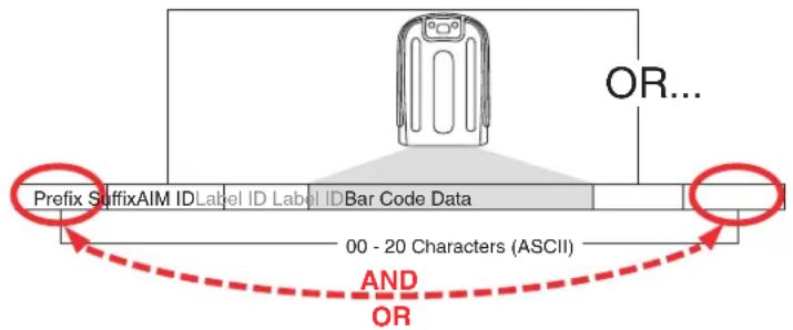
Example: Setting a Prefix
In this example, we'll set a prefix for all symbologies.
- Determine which ASCII character(s) are to be added to scanned barcode data. In this example, we'll add a dollar sign (‘\$’) as a prefix.
- Go to page 52 and scan the ENTER/EXIT PROGRAMMING MODE barcode.
- Scan the SET GLOBAL PREFIX barcode.
- Reference the ASCII Chart on the inside back cover of this manual to find the hex value assigned to the desired character. The corresponding hex number for the '\$' character is 24. To enter this selection code, scan the '2' and '4' barcodes from Appendix D, Keypad.

If you make a mistake before the last character, scan the CANCEL barcode to abort and not save the entry string. You can then start again at the beginning.
- If less than the expected string of 20 characters are selected, scan the ENTER/EXIT barcode to terminate the string.
- Scan the ENTER/EXIT barcode once again to exit Programming Mode.
- The resulting message string would appear as follows:
Scanned barcode data:12345
Resulting message string output: \$12345
Global AIM ID

This feature enables/disables addition of AIM IDs for all symbology types.
AIM label identifiers (as opposed to custom characters you select yourself as with label identifiers) can be included with scanned barcode data. AIM label identifiers consist of three characters as follows:
- A close brace character (ASCII ']), followed by...
• A code character (see the table below), followed by... - A modifier character (the modifier charac ter is symbol dependent).
| SYMBOLOGY CHAR | SYMBOLOGY CHAR | ||
| UPC/EAN | E^a | Code 128/GS1-128 C | |
| Code 39 and Code 32 | A | DataBar Omnidirectional, DataBar Expanded | e |
| Codabar F Standard 2 of 5 S | |||
| Interleaved 2 of 5 I ISBN | x^b | ||
| Code 93 | G | Code 11 | H |
a. UPC-A and UPC-E labels are converted to EAN 13 when adding AIM IDs. b. ISBN (X with a 0 modifier character)
Figure 8. AIM ID

Label ID
A Label ID is a customizable code of up to three ASCII characters (each can be one of hex 0x01-0xFF), used to identify a barcode (symbology) type. It can be appended previous to or following the transmitted barcode data depending upon how this option is enabled. This feature provides options for configuring custom Label IDs as a pre-loaded set (see "Label ID: Pre-loaded Sets" below) or individually per symbology (see "Label ID: Set Individually Per Symbology" on page 249). If you wish to program the reader to always include an industry standard label identifier for ALL symbology types, see "Global AIM ID" on page 53.
Label ID: Pre-loaded Sets
The reader supports two pre-loaded sets of Label IDs. Table 38 shows the USA and the EU sets.

CAUTION
When changing from one Label ID set to another, all other reader configuration settings, including the host interface type, will be erased and set to the standard factory defaults. Any custom configuration or custom defaults will be lost.
Table 38. Label ID Pre-loaded Sets
| Symbology USA Label ID | set EU Label ID set | |||
| ASCII character | Hexidecimal value | ASCII character | Hexidecimal value | |
| ABC Codabar S 530000 S 530000 | ||||
| Anker Plessey o 6F0000 o 6F0000 | ||||
| CODABAR % 250000 R 520000 | ||||
| Codablock F | I | 6C0000 | m | 6D0000 |
| CODE11 | CE | 434500 | b | 620000 |
| CODE128 | # | 230000 | T | 540000 |
| CODE32 | A | 410000 | X | 580000 |
| CODE39 | * | 2A0000 | V | 560000 |
| CODE39 CIP | Y | 590000 | Y | 590000 |
| CODE4 | 4 | 340000 | 4 | 340000 |
| CODE5 | j | 6A0000 | j | 6A0000 |
| CODE93 | & | 260000 | U | 550000 |
| CHINA POSTAL CODE | s | 730000 | s | 730000 |
| EAN13 | F | 460000 | B | 420000 |
| EAN13 P2 | F | 460000 | L | 4C0000 |
| EAN13 P5 | F | 460000 | M | 4D0000 |
| EAN13 P8 | F | 460000 | # | 230000 |
| EAN8 FF 464600 A 410000 | ||||
| EAN8 P2 FF 464600 J 4A0000 | ||||
| EAN8 P5 FF 464600 K 4B0000 | ||||
| EAN8 P8 FF 464600 * 2A0000 | ||||
| FOLLETT 2OF5 O 4F0000 O 4F0000 | ||||
| GS1 DATABAR EXPANDED | RX | 525800 | t | 740000 |
| GS1 DATABAR LIMITED | RL | 524C00 | v | 760000 |
| GS1 DATABAR OMNIDIRECTIONAL | R4 | 523400 | u | 750000 |
| GS1-128 | 000000 | k | 6B0000 | |
| GTIN | G | 470000 | A | 244100 |
| GTIN2 | G2 | 473200 | B | 244200 |
| GTIN5 | G5 | 473500 | C | 244300 |
| GTIN8 | G8 | 473800 | D | 244400 |
| IATA | IA | 494100 | & | 260000 |
| Industrial 2 of 5 | W | 570000 | W | 570000 |
| Interleaved 2 of 5 | i | 690000 | N | 4E0000 |
| Interleaved 2 of 5 CIP HR | e | 650000 | e | 650000 |
| ISBN | l | 490000 | @ | 400000 |
| ISBT128 | f | 660000 | f | 660000 |
| ISSN | n | 6E0000 | n | 6E0000 |
| MSI | @ 400000 Z 5A0000 | |||
| Plessey | a | 610000 | a | 610000 |
| S25 | s | 730000 | P | 500000 |
| UPCA | A | 410000 | C | 430000 |
| UPCA P2 | A | 410000 | F | 460000 |
| UPCA P5 | A | 410000 | G | 470000 |
| UPCA P8 | A | 410000 | Q | 510000 |
Label ID: Set Individually Per Symbology
To configure a Label ID individually for a single symbology:
- Go to page 55 and scan the ENTER/EXIT barcode.
- Select Label ID position as either BEFORE (Enable as Prefix) or AFTER (Enable as suffix) by scanning the appropriate barcode in the section "Label ID Control" on page 56. Reference Figure 9 for Label ID positioning options if multiple identification features are enabled.
- Scan a barcode to select the symbology for which you wish to configure a custom Label ID from the section "Label ID Symbology Selection" on page 57.
- Determine the desired character(s) (you may choose up to three) which will represent the Label ID for the selected symbology.
- Turn to the ASCII Chart on the inside back cover of this manual and find the equivalent hex digits associated with your choice of Label ID. For example, if you wish to select an equal sign (=) as a Label ID, the chart indicates its associated hex characters as 3D. Turn to Keypad, starting on page 279 and scan the barcodes representing the hex characters determined. For the example given, the characters '3' and 'D' would be scanned. More examples of Label ID settings are provided in Table 39.

If you make a mistake before the last character, scan the CANCEL barcode to abort and not save the entry string. You can then start again at the beginning.
- Scan the ENTER/EXIT barcode to exit Label ID entry.
- Scan the ENTER/EXIT barcode once again to exit Programming Mode.
This completes the steps to configure a Label ID for a given symbology.
Figure 9. Label ID Position Options

flowchart
graph TD
    A["Prefix"] --> B["SuffixLabel ID"]
    B --> C["Label IDBar"]
    C --> D["Code DataAim ID"]
    D --> E["OR"]
    style A fill:#f9f,stroke:#333
    style B fill:#ccf,stroke:#333
    style C fill:#cfc,stroke:#333
    style D fill:#fcc,stroke:#333
    style E fill:#ffc,stroke:#333
Table 39. Label ID Examples
| STEP ACTION EXAMPLES | |||||
| 1. Scan the ENTER/EXIT barcode | (Scanner enters Programming Mode) | ||||
| 2. | Determine placement of the Label ID characters BEFORE or AFTER with regard to scanned data using Label ID Control, starting on page 56 | Enable as Prefix | Enable as Suffix | Enable as Prefix | Enable as Suffix |
| 3. | Scan the barcode selecting the symbology type you wish to designate label ID characters for using Label ID Symbology Selection, starting on page 57. | DataBarOmnidirectional | Code 39 Interleaved 2 of 5 Code 32 | ||
| 4. | Custom Label ID example (desired characters): | DB *=C3 +PH | |||
| 5. | Find hex equivalents from the ASCII Chart(inside back cover), then scan in these digits/characters using the barcodes in the section:Keypad, starting on page 279. If you make a mistake before the last character, scan the CANCEL barcode to abort and not save the entry string. You can then start again at the beginning. | 44 42 2A | 3D 43 33 | 2B | 50 48 |
| 6. Scan the ENTER/EXIT barcode | (Scanner exits Label ID entry) | ||||
| 7. | Scan the ENTER/EXIT barcode once again | (Scanner exits Programming Mode) | |||
| Result: | DB*[barcode data] | [barcode data]=C3 | +[barcode data] | [barcode data]PH | |
Character Conversion
Character conversion is an eight byte configuration item. The eight bytes are 4 character pairs represented in hexadecimal ASCII values. The first character in the pair is the character that will be converted. The second character in the pair is the character to convert to. If the character to convert in a pair is FF, then no conversion is done.
For example, if you have the character conversion configuration item set to the following: 41423132FFFFFFF
The first pair is 4142 or AB (41 hex is an ASCII capital A, 42 hex is an ASCII capital B) and the second pair is 3132 or 12 (31 hex is an ASCII 1, 32 is an ASCII 2). The other two pairs are FFFF and FFFF.
With the label, AB12BA21, it would look as follows after the character conversion: BB22BB22.
The A characters were converted to B characters and the 1 characters were converted to 2 characters. Nothing is done with the last two character pairs, since they are all FF.
To set Character Conversion:
- Go to page 64 and scan the ENTER/EXIT barcode.
- Scan the "Configure Character Conversion" barcode.
- Determine the desired string. Sixteen positions must be determined as in the above example. Next, turn to the ASCII Chart on the inside back cover of this manual and find the equivalent hex digits needed to fulfill the string.
- Turn to Appendix D, Keypad and scan the barcodes representing the hex characters determined in the previous step.
- Scan the ENTER/EXIT barcode to exit Programming Mode.

If less than the expected string of 16 characters are selected, scan the ENTER/EXIT barcode twice to accept the selections and exit Programming Mode.
Reading Parameters
Label Gone Timeout
This feature sets the time after the last label segment is seen before the reader prepares for a new label. The timeout can be set within a range of 10 milliseconds to 2,550 milliseconds (2.55 seconds) in 10ms increments. Label Gone Timeout does not apply to scan modes that require a trigger pull for each label that is read
Follow these instructions to set this feature:
- Determine the desired setting in milliseconds.
- Divide the desired setting by 10 (setting is in 10ms increments). Pad the result with leading zeroes to yield three digits. For example: 0 = 000, 5 = 005, 20 = 020, etc.
-
Go to page 67 and scan the ENTER/EXIT PROGRAMMING MODE barcode to enter Programming Mode.
-
Scan the barcode: SELECT LABEL GONE TIMEOUT SETTING.
-
Scan the appropriate three alpha-numeric characters from the keypad in Appendix D, Keypad representing the duration which was determined in the steps above. You will hear a two-beep indication after the last character.

If you make a mistake before the last character, scan the CANCEL barcode to abort and not save the entry string. You can then start again at the beginning.
- Scan the ENTER/EXIT PROGRAMMING MODE barcode to exit Programming Mode.
This completes the procedure. See Table 40 for some examples of how to set this feature.
Table 40. Timeout Setting Examples
| STEP ACTION EXAMPLES | ||||
| 1 Desired Setting | 50ms 150ms | 1800ms (1.8 sec.) | 2550ms (2.55 sec.) | |
| 2 Divide by 10 (and pad with leading zeroes) | 005 015 180 | 255 | ||
| 3 Scan ENTER/EXIT PROGRAMMING MODE | ||||
| 4 Scan SELECT LABEL GONE TIMEOUT SETTING | ||||
| 5 Scan Three Characters From Appendix D, Keypad | ‘0’, ‘0’ and ‘5’ | ‘0’, ‘1’ and ‘5’ | ‘1’, ‘8’ and ‘0’ | ‘2’, ‘5’ and ‘5’ |
| 6 Scan ENTER/EXIT PROGRAMMING MODE | ||||
Good Read LED Duration
This feature specifies the amount of time that the Good Read LED remains on following a good read. The good read LED on time can be set within a range of 10 milliseconds to 2,550 milliseconds (0.001 to 2.55 seconds) in 100ms increments.
Follow these instructions to set this feature:
- Determine the desired setting in milliseconds. A setting of 0 means that the good read LED stays on until the next time the trigger is pulled.
- Divide the desired setting by 10 (setting is in 100ms increments). Pad the result with leading zeroes to yield three digits. For example: 0 = 000, 5 = 000, 20 = 020, etc.
- Go to page 72 and scan the ENTER/EXIT PROGRAMMING MODE barcode to enter Programming Mode.
- Scan the barcode: SELECT GOOD READ LED DURATION SETTING.
- Scan the appropriate three digits from the keypad in Appendix D, Keypad representing the duration which was determined in the steps above. You will hear a two-beep indication after the last character.

If you make a mistake before the last character, scan the CANCEL barcode to abort and not save the entry string. You can then start again at the beginning.
- Scan the ENTER/EXIT PROGRAMMING MODE barcode to exit Programming Mode.
This completes the procedure. See Table 41 for some examples of how to set this feature.
Table 41. Good Read LED Duration Setting Examples
| STEP ACTION EXAMPLES | ||||
| 1 Desired Setting | Good Read LED stays on until next trigger pull (00) | 20ms 150ms | 2550ms (2.55 sec.) | |
| 2 | Divide by 10 (and pad with leading zeroes) | 000 002 015 255 | ||
| 3 Scan ENTER/EXIT PROGRAMMING MODE | ||||
| 4 | Scan SELECT LABEL GONE TIMEOUT SETTING | |||
| 5 | Scan Three Characters From Appendix D, Keypad | ‘0’, ‘0’ and ‘0’ | ‘0’, ‘0’ and ‘2’ | ‘0’, ‘1’ and ‘5’ |
| 6 Scan ENTER/EXIT PROGRAMMING MODE | ||||
Scanning Features
Scan Mode
This mode is associated with typical handheld reader operation. Selects the scan operating mode for the reader. The following selections are valid for all models:
Trigger Single. When the trigger is pulled, scanning is activated until one of the following occurs:
- Scanning Active Time has elapsed
- a label has been read
- the trigger is released
Trigger Hold Multiple. When the trigger is pulled, scanning starts and the product scans until the trigger is released or Scanning Active Time has elapsed. Reading a label does not disable scanning. Double Read Timeout prevents undesired multiple reads of the same label while in this mode.
Trigger Pulse Multiple. When the trigger is pulled, continuous scanning is activated until Scanning Active Time has elapsed or the trigger has been released and pulled again. Double Read Timeout prevents undesired multiple reads of the same label while in this mode.
Flashing. The reader flashes ^1 on and off regardless of the trigger status. Flash rate is controlled by Flash On Time and Flash Off Time. When Flash is ON the imager reads continuously; when Flash is OFF scanning is deactivated.

Flashing is the recommended scan mode for WLS9600 hands-free (stand mode) of operation
Always On. No trigger pull is required to read a barcode. Scanning is continually on. If the trigger is pulled, the reader acts as if it is in Trigger Single Mode. Double Read Timeout prevents undesired multiple reads of the same label while in this mode.
Scanning Active Time
This setting specifies the amount of time that the reader stays in scan ON state once the state is entered. The range for this setting is from 1 to 255 seconds in 1-second increments.
Follow these instructions to set this feature:
- Determine the desired setting.
- Pad the result with leading zeroes to yield three digits. For example: 0 = 000, 5 = 005, 20 = 020, etc.
- Go to page 74 and scan the ENTER/EXIT PROGRAMMING MODE barcode to enter Programming Mode.
- Scan the barcode: SELECT SCANNING ACTIVE TIME SETTING.
- Scan the appropriate three digits from the keypad in Appendix D, Keypad, that represent the duration which was determined in the steps above. You will hear a two-beep indication after the last character.

If you make a mistake before the last character, scan the CANCEL barcode to abort and not save the entry string. You can then start again at the beginning.
- Scan the ENTER/EXIT PROGRAMMING MODE barcode to exit Programming Mode.
This completes the procedure. See Table 42 for some examples of how to set this feature.
Table 42. Scanning Active Time Setting Examples
| STEP ACTION EXAMPLES | ||||
| 1 Desired Setting | 1 Second | 90 Sec. (1.5 min.) | 180 Sec. (3 min.) | 255 Seconds (4.25 min.) |
| 2 Pad leading zero(es) | 001 090 180 255 | |||
| 3 | Scan ENTER/EXIT PROGRAMMING MODE | |||
| 4 | Scan SELECT SCANNING ACTIVE TIME SETTING | |||
| 5 | Scan Three Characters From Appendix D, Keypad | ‘0’, ‘0’ and ‘1’ | ‘0’, ‘9’ and ‘0’ | ‘1’, ‘8’ and ‘0’ |
| 6 | Scan ENTER/EXIT PROGRAMMING MODE | |||
Flash On Time
This feature specifies the ON time for the indicator LED while in Flash Mode. The selectable range is 100 to 9,900 milliseconds (0.1 to 9.9 seconds), in 100 millisecond increments.
Follow these instructions to set this feature.
- Determine the desired setting in milliseconds.
- Divide the desired setting by 100 (setting is in 100ms increments). Pad the result with leading zeroes to yield two digits. For example: 0 = 00 , 5 = 05 , 20 = 20 , etc.
- Go to page 74 and scan the ENTER/EXIT PROGRAMMING MODE barcode to enter Programming Mode.
- Scan the barcode: SELECT FLASH ON TIME SETTING.
- Scan the appropriate two digits from the keypad in Appendix D, Keypad representing the duration which was determined in the steps above. You will hear a two-beep indication after the last character.

If you make a mistake before the last character, scan the CANCEL barcode to abort and not save the entry string. You can then start again at the beginning.
- Scan the ENTER/EXIT PROGRAMMING MODE barcode to exit Programming Mode.
This completes the procedure. See Table 43 for some examples of how to set this feature.
Table 43. Flash On Time Setting Examples
| STEP ACTION EXAMPLES | |||||
| 1 Desired Setting | 500ms | 1,000ms (1 sec.) | 5200ms (5.2 sec.) | 9,900ms (9.9 sec.) | |
| 2 | Divide by 100 (and pad with leading zeroes to yield two digits) | 05 10 52 99 | |||
| 3 Scan ENTER/EXIT PROGRAMMING MODE | |||||
| 4 | Scan SELECT FLASH OFF TIME SETTING | ||||
| 5 | Scan Two Characters From Appendix D, Keypad | ‘0’ and ‘5’ | ‘1’ and ‘0’ | ‘5’ and ‘2’ | ‘9’ and ‘9’ |
| 6 Scan ENTER/EXIT PROGRAMMING MODE | |||||
Flash Off Time
This feature specifies the OFF time for the indicator LED while in Flash Mode. The selectable range is 100 to 9,900 milliseconds (0.1 to 9.9 seconds), in 100 millisecond increments.
Follow these instructions to set this feature.
- Determine the desired setting in milliseconds.
- Divide the desired setting by 100 (setting is in 100ms increments). Pad the result with leading zeroes to yield two digits. For example: 0 = 00 , 5 = 05 , 20 = 20 , etc.
- Go to page 75 and scan the ENTER/EXIT PROGRAMMING MODE barcode to enter Programming Mode.
- Scan the barcode: SELECT FLASH OFF TIME SETTING.
- Scan the appropriate two digits from the keypad in Appendix D, Keypad, that represent the duration which was determined in the steps above. You will hear a two-beep indication after the last character.

If you make a mistake before the last character, scan the CANCEL barcode to abort and not save the entry string. You can then start again at the beginning.
- Scan the ENTER/EXIT PROGRAMMING MODE barcode to exit Programming Mode.
This completes the procedure. See Table 44 for some examples of how to set this feature.
Table 44. Flash Off Time Setting Examples
| STEP ACTION EXAMPLES | |||||
| 1 Desired Setting | 500ms | 1,000ms (1 sec.) | 5200ms (5.2 sec.) | 9,900ms (9.9 sec.) | |
| 2 | Divide by 100 (and pad with leading zeroes to yield two digits) | 05 10 52 | 99 | ||
| 3 | Scan ENTER/EXIT PROGRAMMING MODE | ||||
| 4 | Scan SELECT FLASH OFF TIME SETTING | ||||
| 5 | Scan Two Characters From Appendix D, Keypad | ‘0’ and ‘5’ | ‘1’ and ‘0’ | ‘5’ and ‘2’ | ‘9’ and ‘9’ |
| 6 | Scan ENTER/EXIT PROGRAMMING MODE | ||||
NOTES
Appendix A
Technical Specifications
Table 45 contains Physical and Performance Characteristics, User Environment and Regulatory information. Table 46 provides Standard Cable Pinouts.
Table 45. Technical Specifications
| Item Description | |
| Physical Characteristics | |
| Color | Black/Yellow |
| Dimensions Height 7.1"/181 mm | Length 3.9"/100 mmWidth 2.8"/71 mm |
| Weight (without cable) Approximately 6.0 ounces/169 g | |
| Electrical Characteristics | |
| Voltage & Current Input current at 5V±5% = 260 mA (max)2.5 mA (USB suspend)Standby (typical) <= 30mA | |
| Performance Characteristics | |
| Light Source 650nm Class 2 Laser | |
| Roll (Tilt) Tolerance ± 35° from normal | |
| Pitch Tolerance ± 50° | |
| Skew (Yaw) Tolerance ± 65° | |
| Field of View Scan Angle: 47° (normal) or 35° (narrow) | |
| Depth of Field (Typical)a(5 mil - 1.4" to 6.22" (3,6cm to 15,8cm)13 mila- 0.87" to 18.7" (2,2cm to 47,5cm)20 mil – up to 27.1" (to 69cm) | |
| Minimum Element Width 4 mil | |
| Print Contrast Minimum | 15% minimum reflectance |
| Decode Capability | UPC/EAN/JAN, P2 /P5, ISBN/ISSN; Code 39, Code39 FullASCII; Italian Pharmacode 39, Code39 CIP; Code 128, GS1-128; C128 ISBT; Code 128 addons;1 2 of 5; Standard 2 of 5; I 2 of 5 CIP HR; Industrial 2 of 5; IATA; China Postal Code; Follet 2 of 5; Code 11; Plessey, Anker Plessey; Codabar, ABC Codabar ; Code 93; MSI; GS1 DataBarTM Omnidirectional, GS1 DataBarTM Limited, GS1 DataBarTM Expanded; Code 4, Code 5; Codablock F, Codablock F EAN; |
| Interfaces Supportedb | RS-232 Std, RS-232 Wincor-Nixdorf, RS-232 OPOS, USB Com Std., USB Keyboard, USB Alternate Keyboard,USB OEM, Keyboard Wedge (AT with or w/o Alternate Key, IBM AT PS2 with or w/o Alternate Key, PC-XT, IBM 3153, IBM Terminals 31xx, 32xx,34xx, 37xx make only and make break keyboard, Digital Terminals VT2x, VT3xx, VT4xx, and Apple) and Wano Emulation. |
| User Environment | |
| Operating Temperature 32° to 122° F (0° to 50°C) | |
| Charging Temperature 32° to 104° F (0° to 40°C) | |
| Storage Temperature -4° to 158° F (-20° to 70°C) | |
| Humidity | Operating: 5% to 90% relative humidity, non-condensing |
| Drop Specifications 18 drops from 1.8 meters (5.9 feet) to concrete | |
| Ambient Light Immunity Up to 100,000 Lux | |
| Contaminants Spray/Rain/Dust/Particulates | IP52 |
| ESD Level 16 KV | |
| Regulatory | |
| Electrical Safety | See the Quick Reference Guide for details. |
| EMI/RFI | |
| Laser Safety | |
| LED class safety | |
a. 13 mils DOF based on EAN. All others are Code 39. All labels grade A, typical environmental light, 20°C, label inclination 10°
b. See "Interface Selection" on page 8 for a listing of available interface sets by model type.
Standard Cable Pinouts
Figure 10 and Table 46 provide standard pinout information.
Figure 10. Standard Cable Pinouts

The signal descriptions in Table 46 apply to the connector on the reader and are for reference only.
Table 46. Standard Cable Pinouts — Reader Side
| Pin | RS-232 | OEM | USB | Keyboard Wedge |
| 1 RTS (out) | ||||
| 2 D+ | CLKIN (KBD side) | |||
| 3 D- | DATAIN (KBD side) | |||
| 4 GND | GND GND | GND | ||
| 5 | RX | |||
| 6 | TX | |||
| 7 | VCC | VCC | VCC | VCC |
| 8 | IBM_B | CLKOUT (PC side) | ||
| 9 | IBM_A | DATAOUT (PC side) | ||
| 10 | CTS (in) |
LED and Beeper Indications
The reader's beeper sounds and its LED illuminates to indicate various functions or errors on the reader. An optional “Green Spot” also performs useful functions. The tables below list these indications. One exception to the behaviors listed in the tables is that the reader's functions are programmable, and may or may not be turned on. For example, certain indications such as the power-up beep can be disabled using programming barcode labels.
Table 47. LED and Beeper Indications
| INDICATION DESCRIPTION LED BEEPER | |||
| Power-up Beep The reader is in the process of power-ering-up. | Reader beeps four times at highest frequency and volume upon power-up. | ||
| Good Read Beep A label has been successfully scanned by the reader. | LED behavior for this indication is configurable via the feature “Good Read: When to Indicate” | The reader will beep once at current frequency, volume, mono/bi-tonal setting and duration upon a successful label scan. | |
| ROM Failure There is an error in the reader's software/programming | Flashes | Reader sounds one error beep at highest volume. | |
| Limited Scanning Label Read | Indicates that a host connection is not established when the IBM or USB interface is enabled. | N/A | Reader 'chirps' six times at the highest frequency and current volume. |
| Reader Active Mode | The reader is active and ready to scan. | The LED is lit steadilya | N/A |
| Reader Disabled | The reader has been disabled by the host. | The LED blinks continuously | N/A |
| Green Spot is on continuously | While in Stand Mode or Trigger Stand Mode the green spot shall be on while in stand watch state. | N/A N/A | |
| Green Spota flashes momentarily | Upon successful read of a label, the software shall turn the green spot on for the time specified by the configured value. | N/A N/A | |
a. Except when in sleep mode or when a Good Read LED Duration other than 00 is selected
Table 48. Programming Mode Indications
| Programming Mode - The following indications ONLY occur when the reader is in Programming Mode. | |||
| Label Programming Mode Entry | A valid programming label has been scanned. | LED blinks continuously | Reader sounds four low frequency beeps. |
| Label Programming Mode Rejection of Label | A label has been rejected. | N/A | Reader sounds three times at lowest frequency & current volume. |
| Label Programming Mode Acceptance of Partial Label | In cases where multiple labels must be scanned to program one feature, this indication acknowledges each portion as it is successfully scanned. | N/A | Reader sounds one short beep at highest frequency & current volume. |
| Label Programming Mode Acceptance of Programming | Configuration option(s) have been successfully programmed via labels and the reader has exited Programming Mode. | N/A | Reader sounds one high frequency beep and 4 low frequency beeps followed by reset beeps. |
| Label Programming Mode Cancel Item Entry | Cancel label has been scanned. | N/A | Reader sounds two times at low frequency and current volume. |
Error Codes
Upon startup, if the reader sounds a long tone, this means the reader has not passed its automatic Selftest and has entered FRU (Field Replaceable Unit) isolation mode. If the reader is reset, the sequence will be repeated. The following table describes the LED flashes/beep codes associated with an error found.
| NUMBER OF LED FLASHES/BEEPS | ERROR CORRECTIVE ACTION |
| 1 Configuration | Contact Helpdesk for assistance |
| 2 Interface PCB | |
| 4 Reader Module | |
| 5 Laser Pointer (if so equipped) | |
| 6 Digital PCB | |
| 14 CPLD/Code Mismatch |
NOTES
Appendix B
Standard Defaults
The most common configuration settings are listed in the "Default" column of the table below. Page references are also provided for feature descriptions and programming barcodes for each parameter. A column has also been provided for recording of your preferred default settings for these same configurable features.
Table 49. Standard Defaults
| Parameter Default Your Setting | Page Number | ||
| GLOBAL INTERFACE FEATURES | |||
| Host Commands — Obey/Ignore | Obey 17 | ||
| USB Suspend Mode | Disable 17 | ||
| RS-232 ONLY | |||
| Baud Rate | 9600 20 | ||
| Data Bits | 8 Data Bits 21 | ||
| Stop Bits | 1 Stop Bit 21 | ||
| Parity | None 22 | ||
| Handshaking Control | RTS 23 | ||
| RS-232/USB-Com | |||
| Intercharacter Delay | No Delay 25 | ||
| Beep On ASCII BEL | Disable 25 | ||
| Beep On Not on File | Enable 26 | ||
| ACK Character | 'ACK'28 | ||
| NAK Character | 'NAK' 28 | ||
| ACK NAK Timeout Value | 200 ms | 29 | |
| ACK NAK Retry Count | 3 Retries | 29 | |
| ACK NAK Error Handling | Ignore Errors Detected | 30 | |
| Indicate Transmission Failure | Enable 30 | ||
| Disable Character | 'D' | 31 | |
| Enable Character | 'E' | 31 | |
| Parameter | Default | Your Setting | Page Number |
| KEYBOARD WEDGE | |||
| Country Mode | U.S. Keyboard 34 | ||
| Caps Lock State | Caps Lock OFF 37 | ||
| Numlock | Numlock Key Unchanged 38 | ||
| Send Control Characters | Control Character 00 39 | ||
| Wedge Quiet Interval | 100 ms 40 | ||
| Intercharacter Delay | No Delay 41 | ||
| Intercode Delay | 100 ms 42 | ||
| USB Keyboard Speed | 1 ms 43 | ||
| USB Keyboard Numeric Keypad | Standard Keys 44 | ||
| USB-OEM | |||
| USB-OEM Device Usage | Handheld Scanner 46 | ||
| Interface Options | Ignore Host Configuration Commands | 46 | |
| Wand Emulation | |||
| Wand Signal Speed | 660 ms 48 | ||
| Wand Polarity | Quiet Zones & Spaces High, Bars Low | 48 | |
| Wand Idle State | High 49 | ||
| Transmit Noise | Disable 49 | ||
| Label Symbology Conversion | No conversion 50 | ||
| Data Format | |||
| Global Prefix/Suffix | No Global Prefix Global Suffix = 0x0D (CR) | 52 | |
| Global AIM ID | Disable 53 | ||
| GS1-128 AIM ID | Enable 54 | ||
| Label ID: Pre-loaded Sets | USA Set 55 | ||
| Label ID Control | Disable 56 | ||
| Set Global Mid Label ID Characters | No Mid Label ID Character | 63 | |
| Case Conversion | Disable 64 | ||
| Character Conversion | No Char Conversion | 64 | |
| READING PARAMETERS | |||
| Double Read Timeout | 0.6 Second 65 | ||
| Label Gone Timeout | 160 ms 67 | ||
| Power On Alert | 4 Beeps 68 | ||
| Good Read: When to Indicate | After Decode 68 | ||
| Good Read Beep Type | Mono 69 | ||
| Good Read Beep Frequency | Medium 69 | ||
| Good Read Beep Length | 80 ms 70 | ||
| Good Read Beep Volume | High 71 | ||
| Good Read LED Duration | 300 ms 72 | ||
| Scan Mode | Trigger Single 73 | ||
| Scanning Active Time | 5 Seconds 74 | ||
| Flash On Time | 1 Second 74 | ||
| Flash Off Time | 600 ms 75 | ||
| Green Spot Duration | 300 ms 75 | ||
| Code Selection | |||
| Coupon Control | Enable UPCA coupon decoding | 79 | |
| UPC-A | |||
| UPC-A Enable/Disable | Enable 80 | ||
| UPC-A Check Character Transmission | Enable 80 | ||
| Expand UPC-A to EAN-13 | Don't Expand 81 | ||
| UPC-A Number System Character Transmission | Transmit 81 | ||
| UPC-A Minimum Reads | 1 | 82 | |
| UPC-E | |||
| UPC-E Enable/Disable | Enable 83 | ||
| UPC-E Check Character Transmission | Send | 83 | |
| Expand UPC-E to EAN-13 | Don't Expand 84 | ||
| Expand UPC-E to UPC-A | Don't Expand 84 | ||
| UPC-E Number System Character Transmission | Transmit 85 | ||
| UPC-E Minimum Reads | 2 | 85 | |
| GTIN | |||
| GTIN Formatting | Disable 86 | ||
| EAN 13 (Jan 13) | |||
| EAN 13 Enable/Disable | Enable 87 | ||
| EAN 13 Check Character Transmission | Send 87 | ||
| EAN-13 Flag 1 Character | Transmit 88 | ||
| EAN-13 ISBN Conversion | Disable 88 | ||
| EAN 13 Minimum Reads | 1 | 89 | |
| ISSN | |||
| ISSN Enable/Disable | Disable 90 | ||
| EAN 8 | |||
| EAN 8 Enable/Disable | Enable 91 | ||
| EAN 8 Check Character Transmission | Send 91 | ||
| Expand EAN 8 to EAN 13 | Disable 92 | ||
| EAN 8 Minimum Reads | 1 | 92 | |
| UPC/EAN Global Settings | |||
| UPC/EAN Decoding Level | 2 | 93 | |
| UPC/EAN Correlation | Disable 94 | ||
| UPC/EAN Price Weight Check | Disable 94 | ||
| In-Store Minimum Reads | 2 | 95 | |
| Add-Ons | |||
| Optional Add-ons | Disable P2, P5 and GS1-128 96 | ||
| Optional Add-On Timer | 70 ms 97 | ||
| Optional GS1-128 Add-On Timer | Disable 100 | ||
| P2 Add-Ons Minimum Reads | 2 103 | ||
| P5 Add-Ons Minimum Reads | 1 104 | ||
| GS1-128 Add-Ons Minimum Reads | 1 105 | ||
| Code 39 | |||
| Code 39 Enable/Disable | Enable 106 | ||
| Code 39 Check Character Calculation | Don't Calculate 106 | ||
| Code 39 Check Character Transmission | Don't Send 107 | ||
| Code 39 Start/Stop Character Transmission | Don't Transmit | 108 | |
| Code 39 Full ASCII | Disable 108 | ||
| Code 39 Quiet Zones | Auto 109 | ||
| Code 39 Minimum Reads | 2 110 | ||
| Code 39 Decoding Level | 3 111 | ||
| Code 39 Length Control | Variable 112 | ||
| Code 39 Set Length 1 | 2 113 | ||
| Code 39 Set Length 2 | 50 114 | ||
| Code 39 Interdigit Ratio | 4 115 | ||
| Code 39 Character Correlation | Disable 117 | ||
| Code 39 Stitching | Enable 117 | ||
| Code 32 (Italian Pharmaceutical Code) | |||
| Code 32 Enable/Disable | Disable 118 | ||
| Code 32 Feature Setting Exceptions | N/A 118 | ||
| Code 32 Check Char Transmission | Don't Send 119 | ||
| Code 32 Start/Stop Character Transmission | Don't Transmit 119 | ||
| Code 39 CIP (French Pharmaceutical Code) | |||
| Code 39 CIP Enable/Disable | Disable 118 | ||
| Code 128 | |||
| Code 128 Enable/Disable | Enable 121 | ||
| Expand Code 128 to Code 39 | Don't Expand 121 | ||
| Code 128 Check Character Transmission | Send 122 | ||
| Code 128 Function Character Transmission | Don't Send 122 | ||
| Code 128 Sub-Code Change Transmission | Disable 123 | ||
| Code 128 Quiet Zones | Auto 124 | ||
| Code 128 Minimum Reads | 1 125 | ||
| Code 128 Decoding Level | 3 126 | ||
| Code 128 Length Control | Variable 127 | ||
| Code 128 Set Length 1 | 1 128 | ||
| Code 128 Set Length 2 | 80 129 | ||
| Code 128 Character Correlation | Disable 130 | ||
| Code 128 Stitching | Enable 130 | ||
| Parameter Default Your Setting | Page Number | ||
| GS1-128 | |||
| GS1-128 Enable | Transmit in GS1-128 data format | 131 | |
| ISBT 128 | |||
| ISBT 128 Concatenation | Disable 132 | ||
| ISBT 128 Force Concatenation | Disable 132 | ||
| ISBT 128 Concatenation Mode | Static 133 | ||
| ISBT 128 Dynamic Concatenation Timeout | 200 msec 134 | ||
| Codablock F | |||
| Codablock F Enable/Disable | Disable 135 | ||
| Codablock F EAN Enable/Disable | Disable 135 | ||
| Codablock F AIM Check | Enable check C 136 | ||
| Codablock F Length Control | Variable 136 | ||
| Codablock F Set Length 1 | 3 characters 137 | ||
| Codablock F Set Length 2 | 100 characters 138 | ||
| Interleaved 2 of 5 | |||
| I 2 of 5 Enable/Disable | Disable 139 | ||
| I 2 of 5 Check Character Calculation | Disable 139 | ||
| I 2 of 5 Check Character Transmission | Send 140 | ||
| I 2 of 5 Minimum Reads | 2 162 | ||
| 2 of 5 Decoding Level | 3 162 | ||
| I 2 of 5 Length Control | Variable 143 | ||
| I 2 of 5 Set Length 1 | 6 144 | ||
| I 2 of 5 Set Length 2 | 50 145 | ||
| I 2 of 5 Character Correlation | Disable 146 | ||
| I 2 of 5 Stitching | Disable 146 | ||
| Follett 2 of 5 | |||
| Follett 2 of 5 Enable/Disable | Disable 147 | ||
| Interleaved 2 of 5 CIP HR | |||
| Interleaved 2 of 5 CIP HR Enable/Disable | Disable 147 | ||
| Standard 2 of 5 | |||
| Standard 2 of 5 Enable/Disable | Disable 148 | ||
| Standard 2 of 5 Check Character Calculation | Disable 148 | ||
| Standard 2 of 5 Check Character Transmission | Send 149 | ||
| Standard 2 of 5 Minimum Reads | 2 149 | ||
| Standard 2 of 5 Decoding Level | 3 150 | ||
| Standard 2 of 5 Length Control | Variable 150 | ||
| Standard 2 of 5 Set Length 1 | 8 151 | ||
| Standard 2 of 5 Set Length 2 | 50 152 | ||
| Standard 2 of 5 Character Correlation | Disable 153 | ||
| Standard 2 of 5 Stitching | Disable 153 | ||
| Industrial 2 of 5 | |||
| Industrial 2 of 5 Enable/Disable | Disable 154 | ||
| Industrial 2 of 5 Check Character Calculation | Disable 154 | ||
| Industrial 2 of 5 Check Character Transmission | Enable 155 | ||
| Industrial 2 of 5 Length Control | Variable 155 | ||
| Industrial 2 of 5 Set Length 1 | 1 156 | ||
| Industrial 2 of 5 Set Length 2 | 50 157 | ||
| Industrial 2 of 5 Minimum Reads | 1 158 | ||
| Industrial 2 of 5 Stitching | Disable 158 | ||
| Industrial 2 of 5 Character Correlation | Disable 159 | ||
| Code IATA | |||
| IATA Enable/Disable | Disable 160 | ||
| IATA Check Character Transmission | Enable 160 | ||
| China Postal Code | |||
| China Postal Code Enable/Disable | Disable 161 | ||
| China Postal Code Check Character Calculation | Disable 161 | ||
| China Postal Code Minimum Reads | 2 162 | ||
| China Postal Code Decoding Level | 3 162 | ||
| China Postal Code Length Control | Variable 163 | ||
| China Postal Code Set Length 1 | 6 characters 164 | ||
| China Postal Code Set Length 2 | 50 165 | ||
| China Postal Code Character Correlation | Disable 166 | ||
| China Postal Code Stitching | Disable 166 | ||
| Codabar | |||
| Parameter | Default | Your Setting | Page Number |
| Codabar Enable/Disable | Disable 167 | ||
| Codabar Check Character Calculation | Don't Calculate 167 | ||
| Codabar Check Character Transmission | Send 168 | ||
| Codabar Start/Stop Character Transmission | Transmit 168 | ||
| Codabar Start/Stop Character Set | abcd/abcd 169 | ||
| Codabar Start/Stop Character Match | Don't Require Match 169 | ||
| Codabar Quiet Zones | Auto 170 | ||
| Codabar Minimum Reads | 2 171 | ||
| Codabar Decoding Level | 3 172 | ||
| Codabar Length Control | Variable 172 | ||
| Codabar Set Length 1 | 3 174 | ||
| Codabar Set Length 2 | 50 175 | ||
| Codabar Interdigit Ratio | 4 176 | ||
| Codabar Character Correlation | Disable 178 | ||
| Codabar Stitching | Disable 178 | ||
| ABC Codabar | |||
| ABC Codabar Enable/Disable | Disable 179 | ||
| ABC Codabar Concatenation Mode | Static 179 | ||
| ABC Codabar Dynamic Concatenation Timeout | 200 msec 180 | ||
| ABC Codabar Force Concatenation | Disable 181 | ||
| Code 11 | |||
| Code 11 Enable/Disable | Disable 182 | ||
| Code 11 Check Character Calculation | Check C and K | 182 | |
| Code 11 Check Character Transmission | Send 183 | ||
| Code 11 Minimum Reads | 2 183 | ||
| Code 11 Length Control | Variable 184 | ||
| Code 11 Set Length 1 | 4 185 | ||
| Code 11 Set Length 2 | 50 186 | ||
| Code 11 Interdigit Ratio | 4 187 | ||
| Code 11 Decoding Level | 3 189 | ||
| Code 11 Character Correlation | Disable 190 | ||
| Code 11 Stitching | Disable 190 | ||
| Parameter Default Your Setting | Page Number | ||
| GS1 DataBarTM Omnidirectional | |||
| GS1 DataBarTM Omnidirectional Enable/Disable | Disable 191 | ||
| GS1 DataBarTM Omnidirectional GS1-128 Emulation | Disable 191 | ||
| GS1 DataBarTM Omnidirectional Minimum Reads | 1 192 | ||
| GS1 DataBarTM Expanded | |||
| GS1 DataBarTM Expanded Enable/Disable | Disable 193 | ||
| GS1 DataBarTM Expanded GS1-128 Emulation | Disable 193 | ||
| GS1 DataBarTM Expanded Minimum Reads | 1 194 | ||
| GS1 DataBarTM Expanded Length Control | Variable 194 | ||
| GS1 DataBarTM Expanded Set Length 1 | 1 195 | ||
| GS1 DataBarTM Expanded Set Length 2 | 74 196 | ||
| GS1 DataBarTM Limited | |||
| GS1 DataBarTM Limited Enable/Disable | Disable 197 | ||
| GS1 DataBarTM Limited GS1-128 Emulation | Disable 197 | ||
| GS1 DataBarTM Limited Minimum Reads | 1 198 | ||
| Code 93 | |||
| Code 93 Enable/Disable | Disable 199 | ||
| Code 93 Check Character Calculation | Enable Check C and K 199 | ||
| Code 93 Check Character Transmission | Disable 200 | ||
| Code 93 Length Control | Variable 200 | ||
| Code 93 Set Length 1 | 1 201 | ||
| Code 93 Set Length 2 | 50 202 | ||
| Code 93 Minimum Reads | 1 203 | ||
| Code 93 Decoding Level | 3 204 | ||
| Code 93 Quiet Zones | Auto 205 | ||
| Code 93 Stitching | Enable 206 | ||
| Code 93 Character Correlation | Disable 206 | ||
| MSI | |||
| MSI Enable/Disable | Disable 207 | ||
| MSI Check Character Calculation | Enable Mod10 207 | ||
| MSI Check Character Transmission | Enable 208 | ||
| MSI Length Control | Variable 209 | ||
| MSI Set Length 1 | 1 209 | ||
| MSI Set Length 2 | 50 210 | ||
| MSI Minimum Reads | 4 211 | ||
| MSI Decoding Level | 3 212 | ||
| Plessey | |||
| Plessey Enable/Disable | Disable 213 | ||
| Plessey Check Character Calculation | Enable Plessey std. check char. verification | 214 | |
| Plessey Check Character Transmission | Enable 214 | ||
| Plessey Length Control | Variable 215 | ||
| Plessey Set Length 1 | 1 216 | ||
| Plessey Set Length 2 | 50 217 | ||
| Plessey Minimum Reads | 4 218 | ||
| Plessey Decoding Level | 3 219 | ||
| Plessey Stitching | Disable 220 | ||
| Plessey Character Correlation | Disable 220 | ||
| Code 4 | |||
| Code 4 Enable/Disable | Disable 221 | ||
| Code 4 Check Character Transmission | Send 221 | ||
| Code 4 Hex to Decimal Conversion | Enable 222 | ||
| Code 5 | |||
| Code 5 Enable/Disable | Disable 222 | ||
| Code 5 Check Character Transmission | Send 223 | ||
| Code 5 Hex to Decimal Conversion | Enable 223 | ||
| Code 4 and 5 Common Configuration Items | |||
| Code 4 and 5 Decoding Level | 3 224 | ||
| Code 4 and Code 5 Minimum Reads | 1 225 | ||
| Laser Features | |||
| Laser Scan Angle | 47 degrees 228 | ||
| Laser Idle Mode | Disable 228 | ||
| Bi-Directional Read Decoding | Enable 229 | ||
| Always On Scan Mode Timeout | 5 Hours 230 | ||
The sample barcodes in this appendix are typical representations for their symbology types.
1D Barcodes
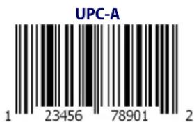

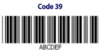


Sample Barcodes (continued)

GS1 DataBar™ (RSS)

GS1 DataBar ^™ variants must be enabled to read the barcodes below (see GS1 DataBar ^™ Omnidirectional on page 191).
GS1 DataBar™ Expanded Stacked

10293847560192837465019283746029478450366523
GS1 DataBar™ Expanded

1234890hjio9900mnb
GS1 DataBar™ Limited

08672345650916
GS1 DataBar™-14
GS1 DataBar™ Omnidirectional Truncated

55432198673467
GS1 DataBar™ Omnidirectional Stacked
90876523412674
GS1 DataBar™ Omnidirectional Stacked
78123465709811
NOTES
Appendix D Keypad
Use the barcodes in this appendix to enter numbers as you would select digits/characters from a keypad.
 | |
 | |
 | |
 | |
 | |
 |
Keypad
 | |
 | |
 | |
 |
HID Variable PIN Code
 Cancel an incomplete HID Variable PIN Code Cancel an incomplete HID Variable PIN Code | |
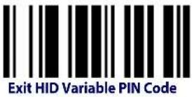 | |
 | |
 | |
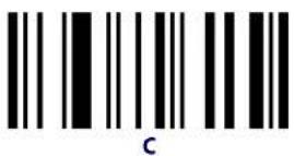 | |
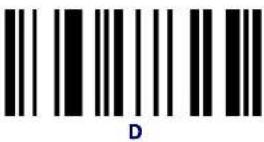 | |
 | |
 |
NOTES
Appendix E
Scancode Tables
Control Character Emulation
Control character emulation selects from different scancode tables as listed in this appendix. Each of the control character sets below are detailed by interface type in the tables. These apply to Wedge and USB Keyboard platforms.
Control Character 00. Characters from 00 to 0x1F are sent as control character Ctrl+Keys, special keys are located from 0x80 to 0xA1.
Control Character 01. Characters from 00 to 0x1F are sent as control character Ctrl+Capital Key, special keys are located from 0x80 to 0xA1.
Control Character 02. Special keys are located from 00 to 0x1F and characters from 0x80 to 0xFE are intended as an extended ASCII table (Microsoft Windows Codepage 1252 — See page 290.)
Single Press and Release Keys
In the following tables, Ar↓ means Alt right pressed and Ar↑ means Alt right released and so on. Definitions for other keys are Al (Alt left), Cr (Control Right) Cl (Control Left) Sh (shift). This method can be used for combining Alt, Control or Shift with other keys.
Example: Consider a Control character set to 00. If AltRight+A is required before sending a label to the host, it could be done by setting three Prefix keys in this way: 0x99 0x41 0x9A.
Interface Type PC AT PS/2, USB-Keyboard or USB-Keyboard for APPLE
Table 50. Scancode Set When Control Character is 00 or 01
| x0 | x1 | x2 | x3 | x4 | x5 | X6 | x7 | x8 | x9 | xA | xB | xC | xD | xE | xF | |
| 0x | NULLC+@ | SOHC(S)+A | STXC(S)+B | ETXC(S)+C | EOTC(S)+D | ENQC(S)+E | ACKC(S)+F | BELC(S)+G | BS | HTTAB | LFC(S)+J | VTC(S)+K | FFC(S)+L | CREnter | SOC(S)+N | SIC(S)+O |
| 1x | DLEC(S)+P | DC1C(S)+Q | DC2C(S)+R | DC3C(S)+S | DC4C(S)+T | NAKC(S)+U | SYNC(S)+V | ETBC(S)+W | CANC(S)+X | EMC(S)+Y | SUBC(S)+Z | ESCEsc | FSC+\ | GSC+] | RSC+^ | USC(S)+_ |
| 2x | SP | ! | " | # | S | % | & | ' | ( | ) | * | ⊥ | , | = | , | / |
| 3x | 0 | 1 | 2 | 3 | 4 | 5 | 6 | 7 | 8 | 9 | : | ; | ≤ | = | ≥ | ? |
| 4x | @ | A | B | C | D | E | F | G | H | I | J | K | L | M | N | O |
| 5x | P | Q | R | S | T | U | V | W | X | Y | Z | [ | \ | ] | ^ | - |
| 6x | : | a | b | c | d | e | f | g | h | i | j | k | l | m | n | o |
| 7x | p | q | r | s | t | u | v | w | x | y | z | { | ↓ | } | = | Del |
| 8x | € | Sh↓ | Sh↑ | Ins | Ent (keyp) | F1 | F2 | F3 | F4 | F5 | F6 | F7 | F8 | F9 | F10 | F11 |
| 9x | F12 | Home | End | Pg Up | Pg Dwn | ↑ | ↓ | ← | → | Ar↓ | Ar↑ | Al↓ | Al↑ | Cl↓ | Cl↑ | Cr↓ |
| Ax | Cr↑ | ' | / | ,, | ... | † | ‡ | ^ | ‰ | Š | < | Š | < | Ø | ||
| Bx | ° | ⊥ | 2 | 3 | ' | μ | ¶ | · | , | ' | ° | » | 1⁄4 | 1⁄2 | 3⁄4 | ; |
| Cx | À | Á | À | Ä | Ä | Ä | Æ | Ç | É | É | É | É | Î | Î | Î | Î |
| Dx | Đ | Ò | Ó | Ô | Ô | Ö | × | ∅ | Ù | Ù | Ù | Ù | Ý | Þ | ß | |
| Ex | à | á | â | ã | ã | ã | æ | ç | è | é | è | è | ì | í | î | ï |
| Fx | ô ñ ó ó ð ð | ÷ ø û ï ù ÿ ÿ ÿ | ||||||||||||||
Extended characters (sky blue) are sent through dedicated keys (when available in the selected country mode) or by using an Alt Mode sequence.
Interface Type PC AT PS/2, USB-Keyboard or USB-Keyboard for APPLE (continued)
Table 51. Scancode Set When Control Character is 02
| x0 | x1 | x2 | x3 | x4 | x5 | X6 | x7 | x8 | x9 | xA | xB | xC | xD | xE | xF | |
| 0x | Ar↓ | Ar↑ | Al↓ | Al ↑ | Cl ↓ | Cl ↑ | Cr ↓ | Cr ↑ | BS | Tab | → | S+ Tab | Enter Keypd | Enter Ins | Pg Up | |
| 1x | Pg Dwn | Home | ← | ↓ | ↑ | F6 | F1 | F2 | F3 | F4 | F5 | ESC | F7 | F8 | F9 | F10 |
| 2x | Space | ! | " | # | S | % | & | ' | ( | ) | * | + | , | - | . | / |
| 3x | 0 | 1 | 2 | 3 | 4 | 5 | 6 | 7 | 8 | 9 | : | ; | < | - | > | ? |
| 4x | @ | A | B | C | D | E | F | G | H | I | J | K | L | M | N | O |
| 5x | P | Q | R | S | T | U | V | W | X | Y | Z | | | \ | | | ^ | _ |
| 6x | ` | a | b | c | d | e | f | g | h | i | j | k | l | m | n | o |
| 7x | p | q | r | s | t | u | v | w | x | y | z | { | | | } | ~ | Del |
| 8x € | ‘ | f | ” | ... | † | ‡ | ^ | ‰ | Š | < | Š | < | Œ | |||
| 9x | , | ’ | “ | ” | • | - | — | ^ | TM | § | , | œ | ž | Ÿ | ||
| Ax | NBSP | ¡ | ¢ | £ | ɔ | ¥ | | | § | - | © | " | « | - | - | ® | - |
| Bx | ° | ± | ? | ? | ’ | μ | ¶ | . | . | ' | ° | » | 1⁄2 | 1⁄2 | 3⁄4 | ¿ |
| Cx | À | Á | Â | Ã | Ã | Â | Æ | Ç | Ê | Ê | Ê | Ê | ì | Í | Î | Î |
| Dx | Đ | Ò | Ó | Ô | Ô | Õ | × | ∅ | Ù | Ù | Û | Û | Ÿ | Þ | ß | |
| Ex | à | á | â | ã | ã | à | æ | ç | é | é | ê | ë | ì | í | î | ï |
| Fx | ð | ñ | ò | ó | ô | ô | ô | : | ø | ù | ú | ù | ù | ÿ | þ | ÿ |
Interface type PC AT PS/2 Alt Mode or USB-Keyboard Alt Mode
Table 52. Scancode Set When Control Character is 00 or 01
| x0 x1 x2 x3 x4 x5 X6 x7 x8 x9 xA xB xC xD xE Xf | ||||||||||||||||
| 0x | Alt+000 | Alt+001 | Alt+002 | Alt+003 | Alt+004 | Alt+005 | Alt+006 | Alt+007 | BS | HT TAB | Alt+010 | Alt+011 Alt+012 | CR Enter | Alt+014 Alt+015 | ||
| 1x | Alt+016 | Alt+017 | Alt+018 | Alt+019 | Alt+020 | Alt+021 | Alt+022 | Alt+023 | Alt+024 | Alt+025 | Alt+026 | ESC Esc | Alt+028 Alt+029 Alt+030 Alt+031 | |||
| 2x | A+032 | A+033 | A+034 | A+035 | A+036 | A+037 | A+038 | A+039 | A+040 | A+041 | A+042 | A+043 | A+044 | A+045 | A+046 | A+047 |
| 3x | A+048 | A+049 | A+050 | A+051 | A+052 | A+053 | A+054 | A+055 | A+056 | A+057 | A+058 | A+059 | A+060 | A+061 | A+062 | A+063 |
| 4x | A+064 | A+065 | A+066 | A+067 | A+068 | A+069 | A+070 | A+071 | A+072 | A+073 | A+074 | A+075 | A+076 | A+077 | A+078 | A+079 |
| 5x | A+080 | A+081 | A+082 | A+083 | A+084 | A+085 | A+086 | A+087 | A+088 | A+089 | A+090 | A+091 | A+092 | A+093 | A+094 | A+095 |
| 6x | A+096 | A+097 | A+098 | A+099 | A+100 | A+101 | A+102 | A+103 | A+104 | A+105 | A+106 | A+107 | A+108 | A+109 | A+110 | A+111 |
| 7x | A+112 | A+113 | A+114 | A+115 | A+116 | A+117 | A+118 | A+119 | A+120 | A+121 | A+122 | A+123 | A+124 | A+125 | A+126 | A+127 |
| 8x | € | Sh↓ | Sh↑ | Ins | Ent (keyp) | F1 | F2 | F3 | F4 | F5 | F6 | F7 | F8 | F9 | F10 | F11 |
| 9x | F12 | Home | End | Pg Up | Pg Dwn | ↑ | ↓ | ← | → | Ar↓ | Ar↑ | Al↓ | Al↑ | Cl↓ | Cl↑ | Cr↓ |
| Ax | Cr↑ | A+0161 | A-0162 | A+0163 | A+0164 | A+0165 | A+0166 | A+0167 | A+0168 | A-0169 | A+0170 | A+0171 | A+0172 | A+0173 | A+0174 | A+0175 |
| Bx | A-0176 | A+0177 | A+0178 | A+0179 | A+0180 | A+0181 | A+0182 | A+0183 | A+0184 | A+0185 | A+0186 | A+0187 | A-0188 | A+0189 | A+0190 | A+0191 |
| Cx | A+0192 | A+0193 | A+0194 | A+0195 | A-0196 | A+0197 | A+0198 | A+0199 | A+0200 | A+0201 | A+0202 | A+0203 | A+0204 | A+0205 | A+0206 | A+0207 |
| Dx | A+0208 | A+0209 | A+0210 | A+0211 | A-0212 | A+0213 | A+0214 | A+0215 | A+0216 | A+0217 | A+0218 | A+0219 | A+0220 | A+0221 | A-0222 | A+0223 |
| Ex | A-0224 | A+0225 | A+0226 | A+0227 | A+0228 | A+0229 | A+0230 | A+0231 | A+0232 | A+0233 | A+0234 | A+0235 | A+0236 | A+0237 | A+0238 | A+0239 |
| Fx | A-0240 | A+0241 | A+0242 | A-0243 | A+0244 | A+0245 | A+0246 | A-0247 | A+0248 | A+0249 | A-0250 | A+0251 | A+052 | A+0253 | A+0254 | A+0255 |
Interface type PC AT PS/2 Alt Mode or USB-Keyboard Alt Mode (continued)
Table 53. Scancode Set When Control Character is 02
| x0 x1 x2 x3 x4 x5 X6 x7 x8 x9 xA xB xC xD xE xF | ||||||||||||||||
| 0x | Ar↓ | Ar↑ | Al↓ | Al ↑ | Cl ↓ | Cl ↑ | Cr ↓ | Cr ↑ | BS | Tab | → | S+ Tab | Enter Keypd | Enter | Ins | Pg Up |
| 1x | Pg Dwn | Home | ← | ↓ | ↑ | F6 | F1 | F2 | F3 | F4 | F5 | ESC | F7 | F8 | F9 | F10 |
| 2x | A+032 | A+033 | A+034 | A+035 | A+036 | A+037 | A+038 | A-039 | A+040 | A+041 | A+042 | A+043 | A+044 | A-045 | A+046 | A+047 |
| 3x | A-048 | A+049 | A+050 | A+051 | A+052 | A+053 | A+054 | A-055 | A+056 | A+057 | A+058 | A+059 | A+060 | A-061 | A+062 | A+063 |
| 4x | A+064 | A+065 | A+066 | A+067 | A+068 | A+069 | A+070 | A-071 | A+072 | A+073 | A+074 | A+075 | A+076 | A-077 | A+078 | A+079 |
| 5x | A-080 | A+081 | A+082 | A-083 | A-084 | A+085 | A+086 | A-087 | A+088 | A+089 | A+090 | A+091 | A+092 | A-093 | A+094 | A+095 |
| 6x | A-096 | A+097 | A+098 | A-099 | A-100 | A+101 | A+102 | A-103 | A+104 | A+105 | A+106 | A+107 | A+108 | A-109 | A+110 | A+111 |
| 7x | A-112 | A+113 | A+114 | A-115 | A+116 | A+117 | A+118 | A-119 | A+120 | A+121 | A+122 | A+123 | A+124 | A-125 | A+126 | A+127 |
| 8x | A+0128 | A-0129 | A+0130 | A+0131 | A-0132 | A-0133 | A+0134 | A+0135 | A-0136 | A+0137 | A+0138 | A+0139 | A+0140 | A+0141 | A+0142 | A-0143 |
| 9x | A+0144 | A-0145 | A+0146 | A+0147 | A-0148 | A-0149 | A+0150 | A+0151 | A-0152 | A+0153 | A+0154 | A+0155 | A+0156 | A+0157 | A+0158 | A-0159 |
| Ax | A+0160 | A+0161 | A-0162 | A+0163 | A+0164 | A+0165 | A-0166 | A+0167 | A+0168 | A-0169 | A+0170 | A+0171 | A-0172 | A-0173 | A+0174 | A+0175 |
| Bx | A+0176 | A+0177 | A-0178 | A+0179 | A+0180 | A+0181 | A-0182 | A+0183 | A+0184 | A-0185 | A+0186 | A+0187 | A-0188 | A-0189 | A+0190 | A+0191 |
| Cx | A-0192 | A+0193 | A+0194 | A+0195 | A+0196 | A-0197 | A+0198 | A+0199 | A-0200 | A+0201 | A+0202 | A+0203 | A+0204 | A+0205 | A+0206 | A-0207 |
| Dx | A-0208 | A+0209 | A+0210 | A+0211 | A+0212 | A-0213 | A+0214 | A+0215 | A-0216 | A+0217 | A+0218 | A+0219 | A+0220 | A+0221 | A+0222 | A-0223 |
| Ex | A+0224 | A+0225 | A-0226 | A+0227 | A+0228 | A+0229 | A+0230 | A+0231 | A+0232 | A-0233 | A+0234 | A+0235 | A-0236 | A-0237 | A+0238 | A+0239 |
| Fx | A+0240 | A-0241 | A+0242 | A+0243 | A+0244 | A+0245 | A-0246 | A+0247 | A+0248 | A-0249 | A+0250 | A+0251 | A+052 | A-0253 | A+0254 | A+0255 |
Digital Interface
Table 54. Scancode Set When Control Character is 00 or 01
| X0 | x1 | x2 | x3 | x4 | x5 | x6 | x7 | x8 | x9 | xA | xB | xC | xD | xE | xF | |
| 0x | NULLC+@ | SOHC(S)+A | STXC(S)+B | ETXC(S)+C | EOTC+D | ENQC(S)+E | ACKC(S)+F | BELC(S)+G | BS | HTTAB | LFC(S)+J | VTC(S)+K | FFC(S)+L | CREnter | SOC(S)+N | SIC(S)+O |
| 1x | DLEC(S)+P | DC1C(S)+Q | DC2C(S)+R | DC3C(S)+S | DC4C(S)+T | NAKC(S)+U | SYNC(S)+V | ETBC(S)+W | CANC(S)+X | EMC(S)+Y | SUBC(S)+Z | ESCEsc | FSC(S)+\ | GSC+] | RSS(S)+^ | USC(S)+_ |
| 2x | Space | ! | “ | # | S | % | & | ‘ | ( | ) | * | + | , | - | . | / |
| 3x 0 | 2 3 4 5 6 7 | 8 9 : | ;<=>? | |||||||||||||
| 4x | @ | A | B | C | D | E | F | G | H | I | J | K | L | M | N | O |
| 5x | P | Q | R | S | T | U | V | W | X | Y | Z | [ | \ | ] | ^ | _ |
| 6x 'a | b c d e f g h i | j k l m n o | ||||||||||||||
| 7x | p | q | r | s | t | u | v | w | x | y | z | { | | | } | ~ | Del |
| 8x | Sh↓ | Sh↑ | Ins | Ent (keyp) | F1 | F2 | F3 | F4 | F5 | F6 | F7 | F8 | F9 | F10 | F11 | |
| 9x | F12 | F13 | F14 | F15 | F16 | ↑ | ↓ | ← | → | Cl ↓ | Cl ↑ | |||||
Table 55. Scancode Set When Control Character is 02
| X0 | x1 | x2 | x3 | x4 | x5 | x6 | x7 | x8 | x9 | xA | xB | xC | xD | xE | xF | |
| 0x | Cl ↓ | Cl ↑ | BS | Tab | à | S+ Tab | Enter Keypd | Enter | Ins | |||||||
| 1x | ← | ↓ | ↑ | F6 | F1 | F2 | F3 | F4 | F5 | ESC | F7 | F8 | F9 | F10 | ||
| 2x | Space | ! | “ | # | S | % | & | * | ( | ) | * | + | , | - | . | / |
| 3x | 0 | 1 | 2 | 3 | 4 | 5 | 6 | 7 | 8 | 9 | ; | ; | < | = | > | ? |
| 4x | @ | A | B | C | D | E | F | G | H | I | J | K | L | M | N | O |
| 5x | P | Q | R | S | T | U | V | W | X | Y | Z | [ | \ | ] | ^ | _ |
| 6x a b c d e f g h i | j k l m n o | |||||||||||||||
| 7x | p | q | r | s | t | u | v | w | x | y | z | { | | | } | ~ | Del |
IBM31xx 102-key
Table 56. Scancode Set When Control Character is 00 or 01
| X0 | x1 | x2 | x3 | x4 | x5 | x6 | x7 | x8 | x9 | xA | xB | xC | xD | xE | xF | |
| 0x | NULLC+@ | SOHC(S)+A | STXC(S)+B | ETXC(S)+C | EOTC+D | ENQC(S)+E | ACKC(S)+F | BELC(S)+G | BS | HTTAB | LFC(S)+J | VTC(S)+K | FFC(S)+L | CREnter | SOC(S)+N | SIC(S)+O |
| 1x | DLEC(S)+P | DC1C(S)+Q | DC2C(S)+R | DC3C(S)+S | DC4C(S)+T | NAKC(S)+U | SYNC(S)+V | ETBC(S)+W | CANC(S)+X | EMC(S)+Y | SUBC(S)+Z | ESCEsc | FSC(S)+\ | GSC+] | RSS(S)+^ | USC(S)+_ |
| 2x | Space | ! | “ | # | S | % | & | ‘ | ( | ) | * | + | , | - | . | / |
| 3x 0 | 2 3 4 5 6 7 | 8 9 : | ;<=>? | |||||||||||||
| 4x | @ | A | B | C | D | E | F | G | H | I | J | K | L | M | N | O |
| 5x | P | Q | R | S | T | U | V | W | X | Y | Z | [ | \ | ] | ^ | _ |
| 6x * a | B c d e f | g h i | k l m n o | |||||||||||||
| 7x | p | q | R | s | t | u | v | w | x | y | z | { | | | } | Del | |
| 8x | Sh↓ | Sh↑ | Ins | Ent(keyp) | F1 | F2 | F3 | F4 | F5 | F6 | F7 | F8 | F9 | F10 | F11 | |
| 9x | F12 | Enter | Reset | Inscrt | Delete | Field - | Field + | Enter paddle | Printl | Ar↓ | Ar↑ | Al↓ | Al ↑ | Cl ↓ | Cl ↑ | Cr ↓ |
| Ax | Cr ↑ |
Table 57. Scancode Set When Control Character is 02
| X0 | x1 | x2 | x3 | x4 | x5 | x6 | x7 | x8 | x9 | xA | xB | xC | xD | xE | xF | |
| 0x | Ar↓ | Ar↑ | Al↓ | Al ↑ | Cl ↓ | Cl ↑ | Cr ↓ | Cr ↑ | BS | Tab | → | S+ Tab | Enter Keypd | Enter | Ins | Pg Up |
| 1x | Pg Dwn | Homc | ← | ↓ | ↑ | F6 | F1 | F2 | F3 | F4 | F5 | ESC | F7 | F8 | F9 | F10 |
| 2x | Space | ! | “ | // | S | % | & | * | ( | ) | * | + | , | - | . | / |
| 3x | 0 | 1 | 2 | 3 | 4 | 5 | 6 | 7 | 8 | 9 | ; | ; | < | = | > | ? |
| 4x | @ | A | B | C | D | E | F | G | H | I | J | K | L | M | N | O |
| 5x | P | Q | R | S | T | U | V | W | X | Y | Z | [ | \ | ] | ^ | _ |
| 6x a | B c d c | f g h i | j k l m n o | |||||||||||||
| 7x | p | q | R | s | t | u | v | w | x | y | z | { | | | } | Del | |
IBM XT
Table 58. Scancode Set When Control Character is 00 or 01
| X0 | x1 | x2 | x3 | x4 | x5 | x6 | x7 | x8 | x9 | xA | xB | xC | xD | xE | xF | |
| 0x | NULLC+@ | SOHC(S)+A | STXC(S)+B | ETXC(S)+C | EOTC+D | ENQC(S)+E | ACKC(S)+F | BELC(S)+G | BSC(S)+H | HTTAB | LFC(S)+J | VTC(S)+K | FFC(S)+L | CREnter | SOC(S)+N | SIC(S)+O |
| 1x | DLEC(S)+P | DC1C(S)+Q | DC2C(S)+R | DC3C(S)+S | DC4C(S)+T | NAKC(S)+U | SYNC(S)+V | ETBC(S)+W | CANC(S)+X | EMC(S)+Y | SUBC(S)+Z | ESCEsc | FSC(S)+\ | GSC+] | RSC(S)+^ | USC(S)+_ |
| 2x | Space | ! | “ | # | S | % | & | ‘ | ( | ) | * | + | , | - | . | / |
| 3x 0 | | 2 3 4 5 6 7 | 8 9 : | ;<=>? | |||||||||||||
| 4x | @ | A | B | C | D | E | F | G | H | I | J | K | L | M | N | O |
| 5x | P | Q | R | S | T | U | V | W | X | Y | Z | [ | \ | ] | ^ | _ |
| 6x - a | B c d e f | g h i | k l m n o | |||||||||||||
| 7x | p | q | R | s | t | u | v | w | x | y | z | { | | | } | Del | |
| 8x | Sh↓ | Sh↑ | Ins | Ent (keyp) | F1 | F2 | F3 | F4 | F5 | F6 | F7 | F8 | F9 | F10 | F11 | |
| 9x | F12 | IHome | End | Pg Up | Pg Dwn | ↑ | ↓ | ← | → | Ar↓ | Ar↑ | Al↓ | Al↑ | Cl↓ | Cl↑ | Cr↓ |
| Ax | Cr ↑ |
Table 59. Scancode Set when Control Character 02
| X0 | x1 | x2 | x3 | x4 | x5 | x6 | x7 | x8 | x9 | xA | xB | xC | xD | xE | xF | |
| 0x | Ar↓ | Ar↑ | Al↓ | Al↑ | Cl↓ | Cl↑ | Cr↓ | Cr↑ | BS | Tab | → | S+ Tab | Enter Keypd | Enter | Ins | Pg Up |
| 1x | Pg Dwn | Home | ← | ↓ | ↑ | F6 | F1 | F2 | F3 | F4 | F5 | ESC | F7 | F8 | F9 | F10 |
| 2x | Space | ! | " | # | S | % | & | * | ( | ) | * | + | , | - | . | / |
| 3x | 0 | 1 | 2 | 3 | 4 | 5 | 6 | 7 | 8 | 9 | : | ; | < | - | > | ? |
| 4x | @ | A | B | C | D | E | F | G | H | I | J | K | L | M | N | O |
| 5x | P | Q | R | S | T | U | V | W | X | Y | Z | [ | \ | ] | ^ | _ |
| 6x‘a | B c d e | f g h i | k l m n o | |||||||||||||
| 7x | p | q | R | s | t | u | v | w | x | y | z | { | | | } | Del |
Microsoft Windows Codepage 1252
Windows-1252 is a character encoding of the Latin alphabet, used by default in the legacy components of Microsoft Windows in English and some other Western languages.
| 00 | 01 | 02 | 03 | 04 | 05 | 06 | 07 | 08 | 09 | 0A | 0B | 0C | 0D | 0E | 0F | |
| 00 | NUL0000 | STX0001 | SOT0002 | ETX0003 | EOT0004 | ENQ0005 | ACK0006 | BEL0007 | BS0008 | HT0009 | LF000A | VT000B | FF000C | CR000D | SO000E | SI000F |
| 10 | DLE0010 | DC10011 | DC20012 | DC30013 | DC40014 | NAK0015 | SYN0016 | ETB0017 | CAN0018 | EM0019 | SUB001A | ESC001B | FS001C | GS001D | RS001E | US001F |
| 20 | SP0020 | !0021 | "0022 | #0023 | $0024 | %0025 | &0026 | '0027 | (0028 | )0029 | *002A | +002B | ,002C | -002D | .002E | /002F |
| 30 | 0030 | 10031 | 20032 | 30033 | 40034 | 50035 | 60036 | 70037 | 80038 | 90039 | :003A | ;003B | <003C | =003D | >003E | ?003F |
| 40 | @0040 | A0041 | B0042 | C0043 | D0044 | E0045 | F0046 | G0047 | H0048 | I0049 | J004A | K004B | L004C | M004D | N004E | O004F |
| 50 | P0050 | Q0051 | R0052 | S0053 | T0054 | U0055 | V0056 | W0057 | X0058 | Y0059 | Z005A | [005B | \005C | ]005D | ^005E | _005F |
| 60 | `0060 | a0061 | b0062 | c0063 | d0064 | e0065 | f0066 | g0067 | h0068 | i0069 | j006A | k006B | l006C | m006D | n006E | o006F |
| 70 | p0070 | q0071 | r0072 | s0073 | t0074 | u0075 | v0076 | w0077 | x0078 | y0079 | z007A | {007B | |007C | }007D | ~007E | DEL007F |
| 80 | €20AC | ,201A | f0192 | ,,201E | ...2026 | †2020 | ‡2021 | ^02C6 | %2030 | Š0160 | <2039 | CE0152 | Ž017D | |||
| 90 | ,2018 | ,2019 | "201C | "201D | •2022 | -2013 | -2014 | ^02DC | m2122 | Š0161 | >203A | oe0153 | Ž017E | Ÿ0178 | ||
| A0 | NBSP00A0 | ;00A1 | ¢00A2 | £00A3 | ¤00A4 | ¥00A5 | |00A6 | §00A7 | "00A8 | @00A9 | a00AA | «00AB | -00AC | -00AD | ®00AE | -00AF |
| B0 | °00B0 | ±00B1 | 200B2 | 300B3 | '00B4 | μ00B5 | ¶00B6 | ·00B7 | ,00B8 | 100B9 | °00BA | »00BB | 1⁄400BC | 1⁄200BD | 3⁄400BE | ¿00BF |
| C0 | À00C0 | Á00C1 | Ã00C2 | Ã00C3 | Ä00C4 | Â00C5 | Â00C6 | Ç00C7 | È00C8 | É00C9 | Ê00CA | È00CB | Ì00CC | Í00CD | Î00CE | Ï00CF |
| D0 | Đ00D0 | Ñ00D1 | Ò00D2 | Ó00D3 | Õ00D4 | Õ00D5 | Õ00D6 | ×00D7 | ∅00D8 | Ù00D9 | Ù00DA | Û00DB | Ù00DC | Ý00DD | Þ00DE | ß00DF |
| E0 | à00E0 | á00E1 | ã00E2 | ã00E3 | ã00E4 | ã00E5 | æ00E6 | ç00E7 | è00E8 | é00E9 | ê00EA | ê00EB | ì00EC | í00ED | î00EE | ì00EF |
| F0 | õ00F0 | ñ00F1 | ò00F2 | ó00F3 | ô00F4 | õ00F5 | ö00F6 | ÷00F7 | ø00F8 | ù00F9 | ú00FA | û00FB | ù00FC | ý00FD | þ00FE | ý00FF |
NOTES
B
barcodes
cancel 279
numeric barcodes 279
RS-232
baud rate 43
RS-232 parameters
parity 37, 147, 221, 222, 225
Beeper
Pitch, Good Read 69
Volume, Good Read 71
Beeper, Good Read 68
C
Cable Pinouts 261
Clear to Send 231
Conversion, case 64
Conversion, character 64, 251
Convert to Code 128 50
Convert to Code 39 50
Coupon Control 79
CTS 231
D
Defaults 265
Dimensions 259
E
Error Codes 263
Errors 263
G
Good Read, Beeper 68
Pitch 69
Volume 71
Good Read, Beeper - 68
Good Read, Beeper Pitch - 69
Good Read, Beeper Volume - 71
Green Spot 262
H
Handheld Scanner 46
I
Idle State (wand) 49
Indications 262
Interface Cable 6
ISSN 90
K
keyboard support 34
KEYBOARD WEDGE (KBW) interface selection 10
Keyboard Wedge Connection 7_
N
numbers lock key 38
P
Performance Characteristics 259
Physical Characteristics 259
Pitch - Good Read, Beeper 69
Polarity (wand) 48
Prefix/Suffix 52, 245
Product Specifications 259
Programming Barcodes 3_
R
Read, Beeper – Good 68
Read, Beeper Pitch – Good 69
Read, Beeper Volume - Good 71
Reading Configuration Barcodes 16
Request to Send 231
RS-232 interface selection 9
RS-232 Serial Connection 6
RTS 231
S
sample barcodes
code 128 275
code 39 275
interleaved 2 of 5 276
Scancode Tables 283
select digits/characters 279
Serial Output 261
Signal Speed (wand) 48
Standard Cable Pinouts 261
Suffix 52, 245
Symbology Conversion 50
symbology types 275
T
Table Top Scanner 46
U
UPC 80
USB Connection 7
USB interface selection 9_
V
Volume - Good Read, Beeper 71
W
Weight 259
X
XON/XOFF 232
ASCII Chart
| ASCII Char. | Hex No. | ASCII Char. | Hex No. | ASCII Char. | Hex No. | ASCII Char. | Hex No. |
| NUL | 00 | SP | 20 | @ | 40 | ‘ | 60 |
| SOH | 01 | ! | 21 | A | 41 | a | 61 |
| STX | 02 | “ | 22 | B | 42 | b | 62 |
| ETX | 03 | # | 23 | C | 43 | c | 63 |
| EOT | 04 | $ | 24 | D | 44 | d | 64 |
| ENQ | 05 | % | 25 | E | 45 | e | 65 |
| ACK | 06 | & | 26 | F | 46 | f | 66 |
| BEL | 07 | ’ | 27 | G | 47 | g | 67 |
| BS | 08 | ( | 28 | H | 48 | h | 68 |
| HT | 09 | ) | 29 | I | 49 | i | 69 |
| LF | 0A | * | 2A | J | 4A | j | 6A |
| VT | 0B | + | 2B | K | 4B | k | 6B |
| FF | 0C | , | 2C | L | 4C | l | 6C |
| CR | 0D | - | 2D | M | 4D | m | 6D |
| SO | 0E | . | 2E | N | 4E | n | 6E |
| SI | 0F | / | 2F | O | 4F | o | 6F |
| DLE | 10 | 0 | 30 | P | 50 | p | 70 |
| DC1 | 11 | 1 | 31 | Q | 51 | q | 71 |
| DC2 | 12 | 2 | 32 | R | 52 | r | 72 |
| DC3 | 13 | 3 | 33 | S | 53 | s | 73 |
| DC4 | 14 | 4 | 34 | T | 54 | t | 74 |
| NAK | 15 | 5 | 35 | U | 55 | u | 75 |
| SYN | 16 | 6 | 36 | V | 56 | v | 76 |
| ETB | 17 | 7 | 37 | W | 57 | w | 77 |
| CAN | 18 | 8 | 38 | X | 58 | x | 78 |
| EM | 19 | 9 | 39 | Y | 59 | y | 79 |
| SUB | 1A | : | 3A | Z | 5A | z | 7A |
| ESC | 1B | ; | 3B | [ | 5B | { | 7B |
| FS | 1C | < | 3C | \ | 5C | | | 7C |
| GS | 1D | = | 3D | ] | 5D | } | 7D |
| RS | 1E | > | 3E | ^ | 5E | ~ | 7E |
| US | 1F | ? | 3F | _ | 5F | DEL | 7F |

BARCODE TECHNOLOGIES
www.waspbarcode.com
Wasp Barcode Technologies
1400 10th Street
Plano, Texas USA 75074

820050590 (Rev. G) January 2014
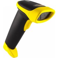
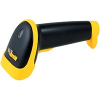


- Wasp Barcode Technologies
- Patents
- Table of Contents
- INTRODUCTION .... 1
- SETUP 5
- CONFIGURATION USING BARCODES 15
- GLOBAL INTERFACE FEATURES 17
- RS-232 ONLY Interface 19
- RS-232/USB-Com Interfaces.... 24
- Keyboard Interface.... 33
- USB-OEM Interface 45
- Wand Emulation Interface 47
- Data Format 51
- Reading Parameters 65
- LED AND BEEPER INDICATORS 68
- SCANNING FEATURES 73
- Code Selection 77
- DISABLE ALL SYMBOLOGIES 78
- CODE EAN/UPC 79
- UPC-E 83
- GTIN FORMATTING 86
- EAN 13 (JAN 13) 87
- FOLLETT 2 OF 5 147
- INTERLEAVED 2 OF 5 CIP HR 147
- STANDARD 2 OF 5 148
- INDUSTRIAL 2 OF 5 154
- CODE IATA 160
- CHINA POSTAL CODE 161
- CODABAR 167
- NOTES
- Chapter 1 Introduction
- About this Manual
- Overview
- Manual Conventions
- References
- Technical Support
- Wasp Website Support
- Telephone Technical Support
- About the Reader
- Programming the Reader
- Configuration Methods
- Programming Barcodes
- Chapter 2 Setup
- Unpacking
- Setting Up the Reader
- Installing the Interface Cable
- RS-232 Serial Connection
- Keyboard Wedge Connection
- USB Connection
- Interface Selection
- Setting the Interface
- Customizing Configuration Settings
- Configure Interface Settings
- Global Interface Features
- Configuring Other Features
- Software Version Transmission
- Resetting the Product Configuration to Defaults
- Restore Factory Configuration
- Chapter 3
- Configuration Using Barcodes
- Configuration Parameters
- Interface Configuration:
- Parameters common to all interface applications:
- Symbology-specific parameters:
- Model-specific parameters:
- Reading Configuration Barcodes
- Host Commands — Obey/Ignore
- USB Suspend Mode
- RS-232 ONLY INTERFACE
- Baud Rate
- Data Bits
- Stop Bits
- Parity
- Handshaking Control
- RS-232/USB-COM INTERFACES
- Intercharacter Delay
- DEFAULT
- Beep On ASCII BEL
- Beep On Not on File
- ACK NAK Options
- ACK Character
- NAK Character
- ACK NAK Timeout Value
- ACK NAK Timeout value is 200ms
- ACK NAK Retry Count
- ACK NAK Error Handling
- Indicate Transmission Failure
- Disable Character
- Enable Character
- KEYBOARD INTERFACE
- Country Mode
- Caps Lock State
- Numlock
- Send Control Characters
- Wedge Quiet Interval
- Intercode Delay
- USB Keyboard Speed
- USB Keyboard Numeric Keypad
- USB-OEM INTERFACE
- USB-OEM Device Usage
- Interface Options
- WAND EMULATION INTERFACE
- Wand Signal Speed
- Wand Polarity
- Wand Idle State
- Transmit Noise
- Label Symbology Conversion
- DATA FORMAT
- Global Prefix/Suffix
- Global AIM ID
- GS1-128 AIM ID
- Label ID
- Label ID: Pre-loaded Sets
- Label ID: Set Individually Per Symbology
- Label ID Control
- Label ID Symbology Selection
- Set Global Mid Label ID Characters
- Case Conversion
- Character Conversion
- READING PARAMETERS
- Double Read Timeout
- Label Gone Timeout
- LED AND BEEPER INDICATORS
- Power On Alert
- Good Read: When to Indicate
- Good Read Beep Type
- Good Read Beep Frequency
- Good Read Beep Volume
- Good Read LED Duration
- SCANNING FEATURES
- Scan Mode
- Scanning Active Time
- Flash On Time
- Flash Off Time
- Green Spot Duration
- CODE SELECTION
- DISABLE ALL SYMBOLOGIES
- CODE EAN/UPC
- Coupon Control
- UPC-A
- UPC-A Enable/Disable
- UPC-A Check Character Transmission
- Expand UPC-A to EAN-13
- UPC-A Number System Character Transmission
- UPC-A Minimum Reads
- UPC-E
- UPC-E Enable/Disable
- UPC-E Check Character Transmission
- Expand UPC-E to EAN-13
- Expand UPC-E to UPC-A
- UPC-E Number System Character Transmission
- UPC-E Minimum Reads
- GTIN FORMATTING
- EAN 13 (JAN 13)
- EAN 13 Enable/Disable
- EAN 13 Check Character Transmission
- EAN-13 Flag 1 Character
- EAN-13 ISBN Conversion
- EAN 13 Minimum Reads
- ISSN
- ISSN Enable/Disable
- EAN 8 (JAN 8)
- EAN 8 Enable/Disable
- EAN 8 Check Character Transmission
- Expand EAN 8 to EAN 13
- EAN 8 Minimum Reads
- UPC/EAN GLOBAL SETTINGS
- UPC/EAN Decoding Level
- UPC/EAN Correlation
- UPC/EAN Price Weight Check
- In-Store Minimum Reads
- ADD-ONS
- Optional Add-ons
- Optional Add-On Timer
- Optional GS1-128 Add-On Timer
- P2 Add-Ons Minimum Reads
- P5 Add-Ons Minimum Reads
- GS1-128 Add-Ons Minimum Reads
- CODE 39
- Code 39 Enable/Disable
- Code 39 Check Character Calculation
- Code 39 Check Character Transmission
- Code 39 Start/Stop Character Transmission
- Code 39 Full ASCII
- Code 39 Quiet Zones
- Code 39 Minimum Reads
- Code 39 Decoding Level
- Code 39 Length Control
- Code 39 Set Length 1
- Code 39 Set Length 2
- Code 39 Interdigit Ratio
- Code 39 Character Correlation
- Code 39 Stitching
- CODE 32 (ITAL PHARMACEUTICAL CODE)
- Code 32 Enable/Disable
- Code 32 Feature Setting Exceptions
- Code 32 Check Char Transmission
- Code 32 Start/Stop Character Transmission
- CODE 39 CIP (FRENCH PHARMACEUTICAL)
- Code 39 CIP Enable/Disable
- CODE 128
- Code 128 Enable/Disable
- Expand Code 128 to Code 39
- Code 128 Check Character Transmission
- Code 128 Function Character Transmission
- Code 128 Sub-Code Change Transmission
- Code 128 Quiet Zones
- Code 128 Minimum Reads
- Code 128 Decoding Level
- Code 128 Length Control
- Code 128 Set Length 1
- Code 128 Set Length 2
- Code 128 Character Correlation
- Code 128 Stitching
- GS1-128
- GS1-128 Enable
- CODE ISBT 128
- ISBT 128 Concatenation
- ISBT 128 Force Concatenation
- ISBT 128 Concatenation Mode
- ISBT 128 Dynamic Concatenation Timeout
- CODABLOCK F
- Codablock F Enable/Disable
- Codablock F EAN Enable/Disable
- Codablock F AIM Check
- Codablock F Length Control
- Codablock F Set Length 1
- Codablock F Set Length 2
- INTERLEAVED 2 OF 5 (I 2 OF 5)
- I 2 of 5 Enable/Disable
- I 2 of 5 Check Character Calculation
- I 2 of 5 Check Character Transmission
- I 2 of 5 Minimum Reads
- of 5 Decoding Level
- of 5 Length Control
- I 2 of 5 Set Length 1
- of 5 Set Length 2
- I 2 of 5 Character Correlation
- I 2 of 5 Stitching
- FOLLETT 2 OF 5
- Follett 2 of 5 Enable/Disable
- INTERLEAVED 2 OF 5 CIP HR
- Interleaved 2 of 5 CIP HR Enable/Disable
- STANDARD 2 OF 5
- Standard 2 of 5 Enable/Disable
- Standard 2 of 5 Check Character Calculation
- Standard 2 of 5 Check Character Transmission
- Standard 2 of 5 Minimum Reads
- Standard 2 of 5 Decoding Level
- Standard 2 of 5 Length Control
- Standard 2 of 5 Set Length 1
- Standard 2 of 5 Set Length 2
- Standard 2 of 5 Character Correlation
- Standard 2 of 5 Stitching
- INDUSTRIAL 2 OF 5
- Industrial 2 of 5 Enable/Disable
- Industrial 2 of 5 Check Character Calculation
- Industrial 2 of 5 Check Character Transmission
- Industrial 2 of 5 Length Control
- Industrial 2 of 5 Set Length 1
- Industrial 2 of 5 Set Length 2
- Industrial 2 of 5 Minimum Reads
- Industrial 2 of 5 Stitching
- Industrial 2 of 5 Character Correlation
- CODE IATA
- IATA Enable/Disable
- IATA Check Character Transmission
- CHINA POSTAL CODE
- China Postal Code Enable/Disable
- China Postal Code Check Character Calculation
- China Postal Code Minimum Reads
- China Postal Code Decoding Level
- China Postal Code Length Control
- China Postal Code Set Length 1
- China Postal Code Set Length 2
- China Postal Code Character Correlation
- China Postal Code Stitching
- CODABAR
- Codabar Enable/Disable
- Codabar Check Character Calculation
- Codabar Check Character Transmission
- Codabar Start/Stop Character Transmission
- Codabar Start/Stop Character Set
- Codabar Start/Stop Character Match
- Codabar Quiet Zones
- Codabar Minimum Reads
- Codabar Decoding Level
- Codabar Length Control
- Codabar Set Length 1
- Codabar Set Length 2
- Codabar Interdigit Ratio
- Codabar Character Correlation
- Codabar Stitching
- ABC CODABAR
- ABC Codabar Enable/Disable
- ABC Codabar Concatenation Mode
- ABC Codabar Dynamic Concatenation Timeout
- ABC Codabar Force Concatenation
- CODE 11
- Code 11 Enable/Disable
- Code 11 Check Character Calculation
- Code 11 Check Character Transmission
- Code 11 Minimum Reads
- Code 11 Length Control
- Code 11 Set Length 1
- Code 11 Set Length 2
- Code 11 Interdigit Ratio
- Code 11 Decoding Level
- Code 11 Character Correlation
- Code 11 Stitching
- GS1 DATABAR™ OMNIDIRECTIONAL
- GS1 DataBar™ Omnidirectional Enable/Disable
- GS1 DataBar™ Omnidirectional GS1-128 Emulation
- GS1 DataBar™ Omnidirectional Minimum Reads
- GS1 DATABAR™ EXPANDED
- GS1 DataBar™ Expanded Enable/Disable
- GS1 DataBar™ Expanded GS1-128 Emulation
- GS1 DataBar™ Expanded Minimum Reads
- GS1 DataBar™ Expanded Length Control
- GS1 DataBar™ Expanded Set Length 1
- GS1 DataBar™ Expanded Set Length 2
- GS1 DATABAR™ LIMITED
- GS1 DataBar™ Limited Enable/Disable
- GS1 DataBar™ Limited GS1-128 Emulation
- GS1 DataBar™ Limited Minimum Reads
- CODE 93
- Code 93 Check Character Calculation
- Code 93 Check Character Transmission
- Code 93 Length Control
- Code 93 Set Length 1
- Code 93 Set Length 2
- Code 93 Minimum Reads
- Code 93 Decoding Level
- Code 93 Quiet Zones
- Code 93 Stitching
- Code 93 Character Correlation
- MSI
- MSI Enable/Disable
- MSI Check Character Calculation
- MSI Check Character Transmission
- MSI Length Control
- MSI Set Length 1
- MSI Set Length 2
- MSI Minimum Reads
- MSI Decoding Level
- PLESSEY
- Plessey Enable/Disable
- Plessey Check Character Calculation
- Plessey Check Character Transmission
- Plessey Length Control
- Plessey Set Length 1
- Plessey Set Length 2
- Plessey Minimum Reads
- Plessey Decoding Level
- Plessey Stitching
- Plessey Character Correlation
- CODE 4
- Code 4 Check Character Transmission
- Code 4 Hex to Decimal Conversion
- CODE 5
- Code 5 Check Character Transmission
- Code 5 Hex to Decimal Conversion
- CODE 4 AND CODE 5 COMMON CONFIGURATION ITEMS
- Code 4 and 5 Decoding Level
- Code 4 and Code 5 Minimum Reads
- LASER FEATURES
- Laser Scan Angle
- Laser Idle Mode
- Bi-Directional Read Decoding
- Always On Scan Mode Timeout
- Chapter 5 References
- RS-232 Parameters
- RS-232 Only
- RS-232/USB COM Parameters
- Options are:
- To set this feature:
- To set the value:
- This feature applies ONLY to the Keyboard Wedge interface.
- If you make a mistake before the last character, scan the CANCEL barcode to abort and not save the entry string. You can then start again at the beginning.
- Symbologies
- Decoding Level
- Set Length
- Set Length 1
- Set Length 2
- Data Editing
- Please Keep In Mind...
- Example: Setting a Prefix
- Flashing is the recommended scan mode for WLS9600 hands-free (stand mode) of operation
- Appendix A
- Technical Specifications
- Standard Cable Pinouts
- LED and Beeper Indications
- Error Codes
- Appendix B
- Standard Defaults
- Sample Barcodes (continued)
- GS1 DataBar™ (RSS)
- GS1 DataBar™-14
- Appendix D Keypad
- Appendix E
- Scancode Tables
- Control Character Emulation
- Single Press and Release Keys
- Interface Type PC AT PS/2, USB-Keyboard or USB-Keyboard for APPLE
- Interface Type PC AT PS/2, USB-Keyboard or USB-Keyboard for APPLE (continued)
- Interface type PC AT PS/2 Alt Mode or USB-Keyboard Alt Mode
- Interface type PC AT PS/2 Alt Mode or USB-Keyboard Alt Mode (continued)
- Digital Interface
- IBM31xx 102-key
- IBM XT
- Microsoft Windows Codepage 1252
- B
- barcodes
- Beeper
- C
- D
- E
- G
- H
- I
- K
- N
- P
- R
- S
- T
- U
- V
- W
- X
- BARCODE TECHNOLOGIES
Brand : Wasp
Model : WLS9600
Category : Barcode Reader