
6140-830 - Grinder MILWAUKEE - Free user manual and instructions
Find the device manual for free 6140-830 MILWAUKEE in PDF.


| Product Type | Angle Grinder (Grinder) |
| Brand | Milwaukee |
| Model | 6140-830 |
| Disc Diameter | 125 mm |
| Power | 1200 W |
| No-load Speed | 11000 rpm |
| Supply Voltage | 230 V / 50-60 Hz |
| Weight | 2.5 kg |
| Protection | Restart protection, soft start |
| Main Functions | Grinding, cutting, deburring |
| Handle | Adjustable anti-vibration side handle |
| Safety | Lockable switch, adjustable protective guard |
| Maintenance and Cleaning | Clean ventilation slots, check carbon brushes |
| Spare parts and repairability | Accessible carbon brushes, repair kit available |
| General Information | CE certified, double insulation |
Frequently Asked Questions - 6140-830 MILWAUKEE
User questions about 6140-830 MILWAUKEE
0 question about this device. Answer the ones you know or ask your own.
Ask a new question about this device
Download the instructions for your Grinder in PDF format for free! Find your manual 6140-830 - MILWAUKEE and take your electronic device back in hand. On this page are published all the documents necessary for the use of your device. 6140-830 by MILWAUKEE.
USER MANUAL 6140-830 MILWAUKEE
Cat. No.
No de cat.
6122-30 6116-30,
6122-30A 6116-31,
6122-31 6116-33,
6122-31A 6160-30,
6140-30 6160-31,
6140-33 6160-33,
6148-30 6123-30,
6148-31 6123-31
6148-33
HEAVY-DUTY SANDERS/GRINDERS
EXTRA ROBUSTE PONCEUSE-RECTIFIEUSE
LIJADORAS/ESMERILADORAS HEAVY-DUTY
TO REDUCE THE RISK OF INJURY, USER MUST READ OPERATOR'S MANUAL.
AFIN DE RÉDUIRE LE RISQUE DE BLESSURES, L'UTILISATEUR DOIT LIRE LE MANUEL DE L'UTILISATEUR.
WARNING READ ALL SAFETY WARNINGS AND INSTRUCTIONS. Failure to follow the warnings and instructions may result in electric shock, fire and/or serious injury. Save all warnings and instructions for future reference The term "power tool" in the warnings refers to your mains-operated (corded) power tool or battery-operated (cordless) power tool.
WORK AREA SAFETY
- Keep work area clean and well lit. Cluttered or dark areas invite accidents.
- Do not operate power tools in explosive atmospheres, such as in the presence of 1 ammable liquids, gases or dust. Power tools create sparks which may ignite the dust or fumes.
- Keep children and bystanders away while operating a power tool. Distractions can cause you to lose control.
ELECTRICAL SAFETY
- Power tool plugs must match the outlet. Never modify the plug in any way. Do not use any adapter plugs with earthed (grounded) power tools. Unmodified plugs and matching outlets will reduce risk of electric shock.
- Avoid body contact with earthed or grounded surfaces such as pipes, radiators, ranges and refrigerators. There is an increased risk of electric shock if your body is earthed or grounded.
- Do not expose power tools to rain or wet conditions. Water entering a power tool will increase the risk of electric shock.
- Do not abuse the cord. Never use the cord for carrying, pulling or unplugging the power tool. Keep cord away from heat, oil, sharp edges or moving parts. Damaged or entangled cords increase the risk of electric shock.
- When operating a power tool outdoors, use an extension cord suitable for outdoor use. Use of a cord suitable for outdoor use reduces the risk of electric shock.
- If operating a power tool in a damp location is unavoidable, use a residual current device (RCD) protected supply. Use of an RCD reduces the risk of electric shock.
PERSONAL SAFETY
- Stay alert, watch what you are doing and use common sense when operating a power tool. Do not use a power tool while you are tired or under the influence of drugs, alcohol or medication. A moment of inattention while operating power tools may result in serious personal injury.
- Use personal protective equipment. Always wear eye protection. Protective equipment such as dust mask, non-skid safety shoes, hard hat, or hearing protection used for appropriate conditions will reduce personal injuries.
- Prevent unintentional starting. Ensure the switch is in the off-position before connecting to power source and/or battery pack, picking up or carrying the tool. Carrying power tools with your anger on the switch or energising power tools that have the switch on invites accidents.
- Remove any adjusting key or wrench before turning the power tool on. A wrench or a key left attached to a rotating part of the power tool may result in personal injury.
Do not overreach. Keep proper footing and balance at all times. This enables better control of the power tool in unexpected situations.
- Dress properly. Do not wear loose clothing or jewellery. Keep your hair, clothing and gloves away from moving parts. Loose clothes, jewellery or long hair can be caught in moving parts.
If devices are provided for the connection of dust extraction and collection facilities, ensure these are connected and properly used. Use of these devices can reduce dust-related hazards.
POWER TOOL USE AND CARE
- Do not force the power tool. Use the correct power tool for your application. The correct power tool will do the job better and safer at the rate for which it was designed.
- Do not use the power tool if the switch does not turn it on and off. Any power tool that cannot be controlled with the switch is dangerous and must be repaired.
Disconnect the plug from the power source and/or the battery pack from the power tool before making any adjustments, changing accessories, or storing power tools. Such preventive safety measures reduce the risk of starting the power tool accidentally.
Store idle power tools out of the reach of children and do not allow persons unfamiliar with the power tool or these instructions to operate the power tool. Power tools are dangerous in the hands of untrained users.
Maintain power tools. Check for misalignment or binding of moving parts, breakage of parts and any other condition that may affect the power tool operation. If damaged, have the power tool repaired before use. Many accidents are caused by poorly maintained power tools.
Keep cutting tools sharp and clean. Properly maintained cutting tools with sharp cutting edges are less likely to bind and are easier to control. Use the power tool, accessories and tool bits etc., In accordance with these Instructions, taking into account the working conditions and the work to be performed. Use of the power tool for operations different from those intended could result in a hazardous situation.
SERVICE
- Have your power tool serviced by a qualified repair person using only identical replacement parts. This will ensure that the safety of the power tool is maintained.
SPECIFIC SAFETY RULES
Safety Warnings Common for Grinding, Sanding, Wire Brushing or Abrasive Cutting-Off Operations:
- This power tool is intended to function as a grinder, sander, wire brush or cut-off tool. Read all safety warnings, instructions, illustrations and specifications provided with this power tool. Failure to follow all instructions listed below may result in electric shock, are and/or serious injury.
- Operations such as polishing are not recommended to be performed with this power tool. Operations for which the power tool was not designed may create a hazard and cause personal injury.
- Do not use accessories which are not specifically designed and recommended by the tool manufacturer. Just because the accessory can be attached to your power tool, it does not assure safe operation.
- The rated speed of the accessory must be at least equal to the maximum speed marked on the power tool. Accessories running faster than their rated speed can break and y apart.
- The outside diameter and the thickness of your accessory must be within the capacity rating of your power tool. Incorrectly sized accessories cannot be adequately guarded or controlled.
- The arbour size of wheels, flanges, backing pads or any other accessory must properly sit the spindle of the power tool. Accessories with arbour holes that do not match the mounting hardware of the power tool will run out of balance, vibrate excessively and may cause loss of control.
- Do not use a damaged accessory. Before each use inspect the accessory such as abrasive wheels for chips and cracks, backing pad for cracks, tear or excess wear, wire brush for loose or cracked wires. If power tool or accessory is dropped, inspect for damage or install an undamaged accessory. After Inspecting and installing an accessory, position yourself and bystanders away from the plane of the rotating accessory and run the power tool at maximum no-load speed for one minute. Damaged accessories will normally break apart during this test time.
- Wear personal protective equipment. Depending on application, use face shield, safety goggles or safety glasses. As appropriate, wear dust mask, hearing protectors, gloves and work shop apron capable of stopping small abrasive or workpiece fragments. The eye protection must be capable of stopping a lying debris generated by various operations. The dust mask or respirator must be capable of a litrating particles generated by your operation.
Prolonged exposure to high intensity noise may cause hearing loss.
- Keep bystanders a safe distance away from work area. Anyone entering the work area must wear personal protective equipment. Fragments of workpiece or of a broken accessory may fly away and cause injury beyond immediate area of operation.
- Hold power tool by Insulated gripping surfaces only, when performing an operation where the cutting accessory may contact hidden wiring or its own cord. Cutting accessory contacting a live wire may make exposed metal parts of the power tool live and shock the operator.
- Position the cord clear of the spinning accessory. If you lose control, the cord may be cut or snagged and your hand or arm may be pulled into the spinning accessory.
- Never lay the power tool down until the accessory has come to a complete stop. The spinning accessory may grab the surface and pull the power tool out of your control.
- Do not run the power tool while carrying it at your side. Accidental contact with the spinning accessory could snag your clothing, pulling the accessory into your body.
- Regularly clean the power tool's air vents. The motor's fan will draw the dust inside the housing and excessive accumulation of powdered metal may cause electrical hazards.
- Do not operate the power tool near flammable materials. Sparks could ignite these materials.
- Do not use accessories that require liquid coolants. Using water or other liquid coolants may result in electrocution or shock.
Kickback and Related Warnings Kickback is a sudden reaction to a pinched or snagged rotating wheel, backing pad, brush or any other accessory. Pinching or snagging causes rapid stalling of the rotating accessory which in turn causes the uncontrolled power tool to be forced in the direction opposite of the accessory's rotation at the point of the binding.
For example, if an abrasive wheel is snagged or pinched by the workpiece, the edge of the wheel that is entering into the pinch point can dig into the surface of the material causing the wheel to climb out or kick out. The wheel may either jump toward or away from the operator, depending on direction of the wheel's movement at the point of pinching. Abrasive wheels may also break under these conditions.
Kickback is the result of power tool misuse and/or incorrect operating procedures or conditions and can be avoided by taking proper precautions as given below.
Maintain a firm grip on the power tool and position your body and arm to allow you to resist kickback forces. Always use auxiliary handle, if provided, for maximum control over kickback or torque reaction during start-up. The operator can control torque reactions or kickback forces, if proper precautions are taken.
- Never place your hand near the rotating accessory. Accessory may kick back over your hand.
- Do not position your body in the area where power tool will move if kickback occurs. Kickback will propel the tool in direction opposite to the wheel's movement at the point of snagging.
- Use special care when working corners, sharp edges etc. Avoid bouncing and snagging the accessory. Corners, sharp edges or bouncing have a tendency to snag the rotating accessory and cause loss of control or kickback.
- Do not attach a saw chain woodcarving blade or toothed saw blade. Such blades create frequent kickback and loss of control.
Safety Warnings Specific for Grinding and Abrasive Cutting-Off Operations: - Use only wheel types that are recommended for your power tool and the special guard designed for the selected wheel. Wheels for which the power tool was not designed can not be adequately guarded and are unsafe.
- The guard must be securely attached to the power tool and positioned for maximum safety, so the least amount of wheel is exposed towards the operator. The guard helps to protect operator from broken wheel fragments and accidental contact with wheel.
- Wheels must be used only for recommended applications. For example: do not grind with the side of cut-off wheel. Abrasive cut-off wheels are intended for peripheral grinding, side forces applied to these wheels may cause them to shatter.
- Always use undamaged wheel ranges that are of correct size and shape for your selected wheel. Proper wheel ranges support the wheel thus reducing the possibility of wheel breakage. Flanges for cut-off wheels may be different from grinding wheel ranges.
- Do not use worn down wheels from larger power tools. Wheel intended for larger power tool is not suitable for the higher speed of a smaller tool and may burst.
Additional Safety Warnings Speci c for Abrasive Cutting-Off Operations: - Do not jam the cut-off wheel or apply excessive pressure. Do not attempt to make an excessive depth of cut. Overstressing the wheel increases the loading and susceptibility to twisting or binding of the wheel in the cut and the possibility of kickback or wheel breakage.
- Do not position your body in line with and behind the rotating wheel. When the wheel, at the point of operation, is moving away from your body, the possible kickback may propel the spinning wheel and the power tool directly at you.
- When wheel is binding or when Interrupting a cut for any reason, switch off the power tool and hold the power tool motionless until the wheel comes to a complete stop. Never attempt to remove the cut-off wheel from the cut while the wheel is in motion otherwise
kickback may occur. Investigate and take corrective action to eliminate the cause of wheel binding.
Do not restart the cutting operation in the workpiece. Let the wheel reach full speed and carefully reenter the cut. The wheel may bind, walk up or kickback if the power tool is restarted in the workpiece.
Support panels or any oversized workpiece to minimize the risk of wheel pinching and kick-back. Large workpieces tend to sag under their own weight. Supports must be placed under the workpiece near the line of cut and near the edge of the workpiece on both sides of the wheel.
Use extra caution when making a "pocketcut" into existing walls or other blind areas. The protruding wheel may cut gas or water pipes, electrical wiring or objects that can cause kickback.
Safety Warnings Speci a c for Sanding Operations:
Do not use excessively oversized sanding disc paper. Follow manufacturers recommendations, when selecting sanding paper. Larger sanding paper extending beyond the sanding pad presents a laceration hazard and may cause snagging, tearing of the disc or kickback.
Safety Warnings Speci c for Wire Brushing Operations:
Be aware that wire bristles are thrown by the brush even during ordinary operation. Do not over stress the wires by applying excessive load to the brush. The wire bristles can easily penetrate light clothing and/or skin.
If the use of a guard is recommended for wire brushing, do not allow any interference of the wire wheel or brush with the guard. Wire wheel or brush may expand in diameter due to workload and centrifugal forces.
Additional Safety Warnings
Maintain labels and nameplates. These carry important information. If unreadable or missing, contact a MILWAUKEE service facility for a free replacement.
WARNING: Some dust created by power sanding, sawing, grinding, drilling, and other construction activities contains chemicals known to cause cancer, birth defects or other reproductive harm.
Some examples of these chemicals are: lead from lead-based paint
crystalline silica from bricks and cement and other masonry products, and
arsenic and chromium from chemically-treated lumber.
Your risk from these exposures varies, depending on how often you do this type of work. To reduce your exposure to these chemicals: work in a well ventilated area, and work with approved safety equipment, such as those dust masks that are specially designed to filter out microscopic particles.
Specifications
| Cat. No. | Volts AC | Amps | No Load RPM | Spindle Thread Size | Wheel Size |
| 6122-30 | 120 | 10 | 10,000 | 5/8"-11 | 4 12 " |
| 6122-30A | 120 | 10 | 10,000 | 5/8"-11 | 5" |
| 6122-31 | 120 | 10 | 10,000 | 5/8"-11 | 4 12 " |
| 6122-31A | 120 | 10 | 10,000 | 5/8"-11 | 5" |
| 6140-30 | 120 | 7.5 | 10,000 | 5/8"-11 | 4 12 " |
| 6140-33 | 120 | 7 | 10,000 | 5/8"-11 | 4 12 " |
| 6148-30 | 120 | 10 | 10,000 | 5/8"-11 | 4 12 " |
| 6148-31 | 120 | 10 | 10,000 | 5/8"-11 | 4 12 " |
| 6148-33 | 120 | 10 | 10,000 | 5/8"-11 | 4 12 " |
| 6116-30 | 120 | 12 | 10,000 | 5/8"-11 | 4 12 "/5" |
| 6116-31 | 120 | 12 | 10,000 | 5/8"-11 | 4 12 "/5" |
| 6116-33 | 120 | 12 | 10,000 | 5/8"-11 | 4 12 "/5" |
| 6160-30 | 120 | 12 | 9,000 | 5/8"-11 | 6" |
| 6160-31 | 120 | 12 | 9,000 | 5/8"-11 | 6" |
| 6160-33 | 120 | 12 | 9,000 | 5/8"-11 | 6" |
| 6123-30 | 120 | 12 | 9,000 | 5/8"-11 | 5"/6" |
| 6123-31 | 120 | 12 | 9,000 | 5/8"-11 | 5"/6" |
Symbology
| Double Insulated | |
| V~ | Volts Alternating Current |
| A | Amps |
| n_0 xxxxmin. ^-1 | No Load Revolutions per Minute (RPM) |
| CULUS | Underwriters Laboratories, Inc. United States and Canada |
| NOMANCE | Mexican Approvals Marking |
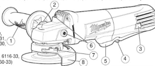
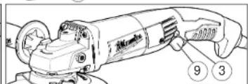
FUNCTIONAL DESCRIPTION
- Side handle
- Spindle lock
- Side handle sockets
- Guard lock lever
- Type 27 guard
- Trigger switch
(Cat.No. 6122-30,
6122-30A, 6122-3
6122-31A. 6123-30.
6123-31) -
Slide switch (Cat.No. 6116-33)
6140-33, 6148-33, 6160-33) -
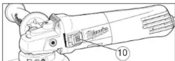
Switch lock-on (Cat.No. 6116-30, 6122-30, 6122-30A, 6123-30, 6140-30, 6148-30, 6160-30)
-
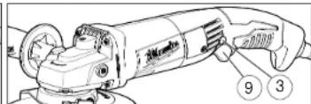
Switch lock-off (Cat.No. 6116-30, 6116-31, 6140-30, 6148-30, 6148-31, 6160-30, 6160-31)
-
Paddle switch (Cat.No. 6116-30, 6116-31, 6140-30, 6148-30, 6148-31, 6160-30, 6160-31)
GROUNDING
WARNING Improperly connecting the grounding wire can result in the risk of electric shock. Check with a qualified electrician if you are in doubt as to whether the outlet is properly grounded. Do not modify the plug provided with the tool. Never remove the grounding prong from the plug. Do not use the tool if the cord or plug is damaged. If damaged, have it repaired by a MILWAUKEE service facility before use. If the plug will not sit the outlet, have a proper outlet installed by a qualified electrician.
Grounded Tools: Tools with Three Prong Plugs
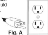
Tools marked "Grounding Required" have a three wire cord and three prong grounding plug. The plug must be connected to a properly grounded outlet (See Figure A). If the tool should electrically malfunction or break down, grounding provides a low resistance path to carry electricity away from the user, reducing the risk of electric shock.
The grounding prong in the plug is connected through the green wire inside the cord to the grounding system in the tool. The green wire in the cord must be the only wire connected to the tool's grounding system and must never be attached to an electrically "live" terminal.
Your tool must be plugged into an appropriate outlet, properly installed and grounded in accordance with all codes and ordinances.
The plug and outlet should look like those in Figure A.
Double Insulated Tools: Tools with Two Prong Plugs
Tools marked "Double Insulated" do not require grounding. They have a special double insulation system which satisfies OSHA requirements and complies with the applicable standards of Underwriters Laboratories, Inc., the Canadian Standard Association and the National Electrical Code. Double Insulated tools may be used in either of the 120 volt outlets shown in Figures B and C. Fig. B Fig. C
EXTENSION CORDS
Grounded tools require a three wire extension cord. Double insulated tools can use either a two or three wire extension cord. As the distance from the supply outlet increases, you must use a heavier gauge extension cord. Using extension cords with inadequately sized wire causes a serious drop in voltage, resulting in loss of power and possible tool damage. Refer to the table shown to determine the required minimum wire size.
The smaller the gauge number of the wire, the greater the capacity of the cord. For example, a 14 gauge cord can carry a higher current than a 16 gauge cord. When using more than one extension cord to make up the total length, be sure each cord contains at least the minimum wire size required. If you are using one extension cord for more than one tool, add the nameplate amperes and use the sum to determine the required minimum wire size.
Guidelines for Using Extension Cords
- If you are using an extension cord outdoors, be sure it is marked with the suffix "W-A" ("W" in Canada) to indicate that it is acceptable for outdoor use.
- Be sure your extension cord is properly wired and in good electrical condition. Always replace a damaged extension cord or have it repaired by a qualified person before using it.
- Protect your extension cords from sharp objects, excessive heat and damp or wet areas.
Recommended Minimum Wire Gauge for Extension Cords*
| Nameplate Amperes | Extension Cord Length | ||||
| 25' | 50' | 75' | 100' | 150' | |
| 0 - 2.0 | 18 | 18 | 18 | 18 | 16 |
| 2.1 - 3.4 | 18 | 18 | 18 | 16 | 14 |
| 3.5 - 5.0 | 18 | 18 | 16 | 14 | 12 |
| 5.1 - 7.0 | 18 | 16 | 14 | 12 | 12 |
| 7.1 - 12.0 | 16 | 14 | 12 | 10 | |
| 12.1 - 16.0 | 14 | 12 | 10 | ||
| 16.1 - 20.0 | 12 | 10 | |||
* Based on limiting the line voltage drop to five volts at 150% of the rated amperes.
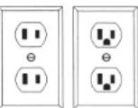
Fig. B Fig. C
READ AND SAVE ALL INSTRUCTIONS FOR FUTURE USE.
ASSEMBLY
WARNING To reduce the risk of injury, always unplug tool before attaching or removing accessories or making adjustments. Use only specifically recommended accessories. Others may be hazardous.
Installing Side Handle
The side handle may be installed on either side (all models) or the top (select models) of the gear case. Position the side handle in the location which offers best control and guard protection. To install, thread side handle into side handle socket and tighten securely.
WARNING To reduce the risk of injury when grinding:
• ALWAYS use the proper guard.
- ALWAYS properly install the guard.
- ALWAYS hold the tool armly with both hands using the handles provided before and during grinding.
- NEVER use a wheel that has been dropped.
- NEVER bang grinding disc onto work.
- NEVER grind without proper safety equipment.
Installing, Removing and Adjusting the Guard. This tool is shipped with a guard. The guard must be used when using the tool as a grinder. The guard may be removed when using tool as a sander.
- To remove the guard, unplug tool and remove any accessories from spindle.
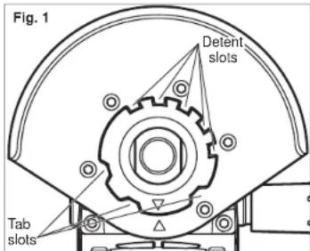
- Press in the lock lever and rotate the guard to line up the tabs on the grinder with the slots in the guard.
- Press in the lock lever and lift the guard straight up and away from the tool.
- To install the guard, unplug the tool and remove any accessories from the spindle.
- Line up the tabs on the grinder with the slots in the guard.
- Press in the lock lever and press the guard onto the tool.
- To adjust the guard, press in the lock lever and rotate the guard to one of five detent slots.
WARNING Only use accessories with Maximum Safe Operating Speed rated at least equal to the maximum speed marked on the power tool. This speed is based on the strength of the wheel, allowing for a reasonable measure of safety. It is not meant to imply a best or most efficient operating speed. Do not exceed the Maximum Safe Operating Speed.
Installing/Removing Accessories
Make sure the grinding wheel does not extend beyond the bottom of the guard. Threaded hub grinding wheels may require a deeper guard (see "Accessories").
- Unplug the tool.
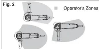
- Properly position the guard (Fig. 2).
- Wipe the flange, flange nut and spindle to remove dust and debris. Inspect the parts for damage. Replace if needed.
- Place the flange on spindle, as shown.
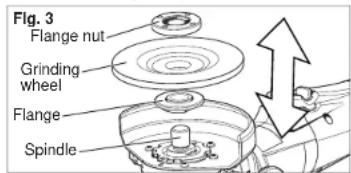
- Place the selected wheel on the spindle and align it with the range.
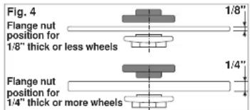
- Position the □ange nut over the spindle according to wheel thickness (Fig. 4).
OPERATION

WARNING To reduce the risk of injury, ys unplug tool before attaching or remov- accessories or making adjustments. Use speci cally recommended accessories. rs may be hazardous.

WARNING To reduce the risk of injury, safety goggles or glasses with side ds.
Controlled Start (6116-30, 6116-31, 6116-33, 6123-30, 6123-31, 6160-30, 6160-31, 6160-33) The controlled start feature reduces the torque reaction "jerk" when its trigger is pulled.
Constant Speed Tachometer (6116-30, 6116-31, 6116-33, 6123-30, 6123-31, 6160-30, 6160-31, 6160-33)
The constant speed tachometer keeps the tool's revolutions per minute at an almost constant speed even under load. The tachometer also helps prevent tool overheating. The tool switches itself off automatically when the motor is overloaded. If this happens, release the trigger to reset. Pull the trigger and continue work.
Slide Switch Operation
(6116-33, 6140-33, 6148-33, 6160-33)
Tostart the tool, grasp the handle and side handle firmly and slide the switch to ON.
To stop the tool, release the switch. Make sure the tool comes to a complete stop before laying the tool down.
To lock-on the switch, slide the switch to ON and press down on the front of the switch. To stop the tool, press and release the switch. Make sure the tool comes to a complete stop before laying it down.
Paddle Switch Operation (6116-30, 6116-31, 6140-30, 6148-30, 6148-31, 6160-30, 6160-31) Tostart the tool, grasp the handle and side handle firmly. Pull the lock-off button back and squeeze the paddle switch.
Tostop the tool, release the paddle switch. Make sure the tool comes to a complete stop before laying the tool down.
To lock-on the switch (6116-30, 6140-30, 6148-30, 6160-30 only), start the tool and push in the lock-on button. To stop the tool, squeeze and release the paddle switch. Make sure the tool comes to a complete stop before laying the tool down.
Trigger Switch Operation (6122-30, 6122-30A, 6122-31, 6122-31A, 6123-30, 6123-31)
To start the tool, grasp the handle and side handle firmly and pull the trigger.
To stop the tool, release the trigger. Make sure the tool comes to a complete stop before laying the tool down.
To lock-on the switch (6122-30, 6122-30A, 6123-30 only), start the tool and push in the lock-on button. To stop the tool, pull and release the trigger. Make sure the tool comes to a complete stop before laying it down.
General Operation
- If you have just installed an accessory or are beginning a period of work, test it by letting it spin for one minute before applying it to the workpiece. Out-of-balance or damaged accessories can mar workpiece, damage the tool, and cause stress that may cause accessory failure.
- Use a clamp, vise or other practical means to hold your work, freeing both hands to control the tool.
3 Hold tool securely with both hands - Start the tool.
- Allow accessory to come to full speed before beginning work.
- Control pressure and surface contact between accessory and workpiece. Too much pressure slows speed.
- When finished, turn off the tool and make sure it comes to a complete stop before laying it down.
USING GRINDING WHEELS

WARNING To reduce the risk of injury, operator should be instructed in the use, and protection of grinding wheels.
Grinding Wheel Selection
Use grinding wheels, and accessories that are: - correct size as written on tool's nameplate.
- rated at or above the RPM listed on the tool's nameplate.
- correct accessory, wheel type and grit for the job. Grinding is the cutting action of thousands of abrasive grains on the face of a grinding wheel. When grinding metals such as steel and iron, choose an aluminum oxide grinding wheel. Select a silicon carbide grinding wheel for stone and concrete. Use cotton reinforced wheels for non-ferrous metals. Type 27 Reinforced 1/8" thick or less Cut-Off Wheels are suited for small cut-off and shallow notching operations only. Always handle wheels carefully to avoid damage. Before installing any wheel, always inspect it for cracks. If wheel is cracked, discard it to prevent others from using it.
Care of Grinding & Cut-Off Wheels
Grinding/cut-off wheels should be protected from:
- wetness and extreme humidity
- any type of solvent
- extreme changes in temperature
- dropping and bumping
Grinding and cut-off wheels should be stored:
- in an organized way so wheels can be removed without disturbing or damaging other wheels
• with their safety information
Grinding and cut-off wheels should NOT be dropped, rolled or bumped.
Discard wheels that have been dropped, rolled, bumped, subjected to extreme changes in temperature, or come into contact with solvents or wetness.
Grinding
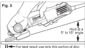
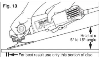
When grinding, hold tool at a 5° to 15° angle, using constant pressure for a uniform finish. Too great an angle causes concentrated pressure on small areas which may gouge or burn work surface.
USING CUT-OFF WHEELS

WARNING A Type "1" guard must be called when using a cut-off wheel to provide maximum protection for the operator if the set should break.
Type "1" Cut-Off Wheels are suited for small cut-off and shallow notching operations only.
When using a cut-off wheel, hold the tool as shown, using only the edge of the wheel.
Fig. 6
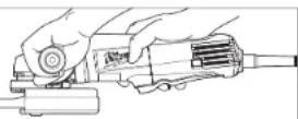

WARNING Using the face of a Cut-Offel (as in grinding) will cause the Wheelack and break, resulting in serious per-1 injury.
USING WIRE BRUSHES

WARNING Everyone in the area must wear protective clothing and safety styles or face shields. Fatigued wires and blue will play off the brush with considerable use, causing potential for serious injury.
Wire brushes are useful for removing rust, scale, burrs, weld slag, etc.
Always install wire cup brushes according to the accessory manufacturer's instructions.
Fig. 7
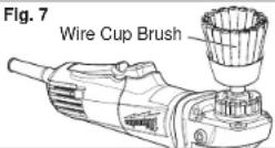

WARNING Because the wires on wire wheel brushes are directed towards theator, a guard must be used to protect theator when fatigued wires break.
When using a wire wheel brush, install guard according to "Installing/Removing Accessories".
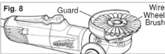
Test wheel for balance and loose or damaged wires by letting it spin for one minute before applying it to the workpiece. During this time, no one should stand in front of or in line with it.
Control pressure and surface contact between wheel and workpiece. Too much pressure causes over-bending of wires and heat build-up causing premature wire breaking, rapid dulling and reduced brush life. Instead of more pressure, try a wire wheel with more aggressive cutting action (increased wire size, decreased wire length or different brush type (knot type vs.crimped wire type).
WARNING Never exceed Maximum Safe Operating Speed of brush. Do not use a damaged brush or one that is functioning Improperly (throwing wires, out-of-balance, etc.). These conditions increase the possibility of further brush failure and possible Injury. Discard and replace damaged brushes immediately.
USING SANDING DISCS
Sanding Disc Selection
Use sanding discs and accessories that are:
- correct size as written on tool's nameplate.
- rated at or above the RPM listed on the tool's nameplate.
- correct accessory, wheel type and grit for the job. Refer to the table below to select the correct type of sanding disc for your job. Generally, use 24 or 36 grit for heavy stock removal; 50, 60, or 80 grit for medium stock removal and 120 grit for nishing. Always begin with a coarse grit, using successively inner grits to obtain the desired finish. See your MILWAUKEE Electric Tool Catalog for a complete list of sanding discs.
Aluminum Oxide
For fast cutting, general purpose discs for most metal jobs. Best for cold-rolled steel, stainless steel or metals requiring tough, fast cutting, long lasting abrasives.
Aluminum Zirconia Bi-Cut
Unique grit pattern is arranged in clusters for faster stock removal and cleaning. Ideal for removing paint from cars, boats, etc. without clogging.
Ceramic
Lasts up to 3 times longer than Aluminum Oxide Discs. For general metal working. Ideal for tough jobs.
Installing Backing Pad and Sanding Discs
-
Unplug the tool.
-
Wipe the accessories, disc nut and spindle to remove dust and debris. Inspect the parts for damage. Replace if needed.
-
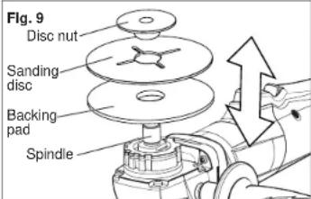
Slip backing pad onto spindle with flat side away from gear case.
-
Place sanding disc on backing pad and secure assembly to spindle with disc nut.
-
To tighten, press the spindle lock button while turning disc nut clockwise with the spanner wrench provided.
-
To remove backing pad and sanding disc, unplug the tool and reverse the procedure.
Sanding
Hold tool at 5^ to 15^ angle to ensure proper sanding pressure and control. Too great an angle will result in too much pressure and could cause excessive wear to the disc and workpiece. Too small an angle will reduce control.
Use long, sweeping, side to side strokes, advancing forward to produce the desired finish.
Cross Sanding
When finishing a surface that has been prepared by a coarse disc or wheel, sand at right angles to the strokes made by the coarser disc. Finishing marks left from previous sanding are easily seen and removed for a uniform finish. Failure to cross sand when changing from a coarse disc to a finishing disc may result in deep scratches and circular marks.
Removing Welds or Hammer Marks
When removing welds or hammer marks, limit coarse sanding to the immediate area. Use successively inner grits to smooth surface.
Finishing Metal
Constantly move across the surface. Work faster on curved surfaces where contact areas are smaller and pressure is greater. Flat areas may appear at the end of the stroke when pressure is too heavy. Ease up on pressure at end of each stroke and when reversing strokes.
Troubleshooting
Deep scratches and circular marks can result from:
• Using too coarse a grit
• Using a partially glazed disc
- Dirt or loose metal on the workpiece
- Failure to sand across the grain when changing from coarse to finishing discs
- Failure to use closed coated discs to reduce the problem of grains working loose and scratching the workpiece
Bluish discoloration of metal surface indicates:
• Excessive heat caused by circular motion in a small area
• Excessive pressure
• Use of worn out or glazed discs
MAINTENANCE
WARNING To reduce the risk of injury, always unplug your tool before performing any maintenance. Never disassemble the tool or try to do any rewiring on the tool's electrical system. Contact a MILWAUKEE service facility for ALL repairs.
Maintaining Tools
Keep your tool in good repair by adopting a regular maintenance program. Before use, examine the general condition of your tool. Inspect guards, switches, tool cord set and extension cord for damage. Check for loose screws, misalignment, binding of moving parts, improper mounting, broken parts and any other condition that may affect its safe operation. If abnormal noise or vibration occurs, turn the tool off immediately and have the problem corrected before further use. Do not use a damaged tool. Tag damaged tools "DO NOT USE" until repaired (see "Repairs").
Under normal conditions, relubrication is not necessary until the motor brushes need to be replaced. After six months to one year, depending on use, return your tool to the nearest MILWAUKEE service facility for the following:
- Lubrication
• Brush inspection and replacement
- Mechanical inspection and cleaning (gears, spindles, bearings, housing, etc.)
• Electrical inspection (switch, cord, armature, etc.)
- Testing to assure proper mechanical and electrical operation
WARNING To reduce the risk of Injury, electric shock and damage to the tool, never immerse your tool in liquid or allow a liquid to flow inside the tool.
Cleaning
Clean dust and debris from vents. Keep the tool handles clean, dry and free of oil or grease. Use only mild soap and a damp cloth to clean your tool since certain cleaning agents and solvents are harmful to plastics and other insulated parts. Some of these include: gasoline, turpentine, lacquer thinner, paint thinner, chlorinated cleaning solvents, ammonia and household detergents containing ammonia. Never use ammable or combustible solvents around tools.
Repairs
If your tool is damaged, return the entire tool to the nearest service center.
ACCESSORIES
WARNING To reduce the risk of injury, always unplug the tool before attaching or removing accessories. Use only specifically recommended accessories. Others may be hazardous.
For a complete listing of accessories refer to your MILWAUKEE Electric Tool catalog or go on-line to www.milwaukeetool.com. To obtain a catalog, contact your local distributor or a service center.
LIMITED WARRANTY - USA AND CANADA
Every MILWAUKEE power tool (including cordless product - tool, battery pack(s) & battery charger and Work Light - cordless taashlight) is warranted to the original purchaser only to be free from defects in material and workmanship. Subject to certain exceptions, MILWAUKEE will repair or replace any part on an electric power tool which, after examination, is determined by MILWAUKEE to be defective in material or workmanship for a period of five (5) years' after the date of purchase. Return of the power tool and a copy of proof of purchase to a MILWAUKEE factory Service Center location or MILWAUKEE Authorized Service Station, freight prepaid and insured, are required for this warranty to be effective. This warranty does not apply to damage that MILWAUKEE determines to be from repairs made or attempted by anyone other than MILWAUKEE authorized personnel, misuse, alterations, abuse, normal wear and tear, lack of maintenance, or accidents.
*Every MLWAUKEE VT ^™ technology (V18 ^™ & V28 ^™ LITHIUM-ION Battery Pack and M18 XC LITHIUM-ION Battery Pack is warranted for five (5) years / 2000 charges on the date of purchase, whichever first occurs. The first 1000 charges or 2 years of the warranty, whichever first occurs, are covered through free replacement of the defective battery. This means that for the earlier of the first 1000 charges or two (2) years from the date of purchase/first charge, a replacement battery will be provided to the customer for any defective battery free of charge. Thereafter, the remaining charges up to a total of 2000 or the remainder of the five (5) year period from the date of purchase, whichever first occurs, will be covered on a pro rata basis. This means that every customer gets an additional 1000 charges or three (3) years of pro rata warranty on the V18 ^™ technology LITHIUM-ION Battery Pack and M18 XC LITHIUM-ION Battery Pack depending upon the amount of use.
*The warranty period for ALL other LITHIUM-ION Battery Packs is two (2) years from the date of purchase.
*The warranty period for M12 2-Beam Laser & M12 Power Port, Ni-CD Battery Packs, Job Sile Radios. and Trade Titan™ Industrial Work Carls is one (1) year from the date of purchase.
Warranty Registration is not necessary to obtain the applicable warranty on a MILWAUKEE product. The manufacturing date of the product will be used to determine the warranty period if no proof of purchase is provided at the time warranty service is requested.
ACCEPTANCE OF THE EXCLUSIVE REPAIR AND REPLACEMENT REMEDIES DESCRIBED HEREIN IS A CONDITION OF THE CONTRACT FOR THE PURCHASE OF EVERY MILWAUKEE PRODUCT. IF YOU DO NOT AGREE TO THIS CONDITION, YOU SHOULD NOT PURCHASE THE PRODUCT. IN NO EVENT SHALL MILWAUKEE BE LIABLE FOR ANY INCIDENTAL, SPECIAL, CONSEQUENTIAL OR PUNITIVE DAMAGES, OR FOR ANY COSTS, ATTORNEY FEES, EXPENSES, LOSSES OR DELAYS ALLEGED TO BE AS A CONSEQUENCE OF ANY DAMAGE TO FAILURE OF, OR DEFECT IN ANY PRODUCT INCLUDING, BUT NOT LIMITED TO ANY CLAIMS FOR LOSS OF PROFITS. SOME STATES DO NOT ALLOW THE EXCLUSION OR LIMITATION OF INCIDENTAL OR CONSEQUENTIAL DAMAGES, SO THE ABOVE LIMITATION OR EXCLUSION MAY NOT APPLY TO YOU. THIS WARRANTY IS EXCLUSIVE AND IN LIEU OF ALL OTHER EXPRESS WARRANTIES, WRITTEN OR ORAL. TO THE EXTENT PERMITTED BY LAW, MILWAUKEE DISCLAIMS ANY IMPLIED WARRANTIES, INCLUDING WITHOUT LIMITATION ANY IMPLIED WARRANTY OF MERCHANTABILITY OR FITNESS FOR A PARTICULAR USE OR PURPOSE; TO THE EXTENT SUCH DISCLAIMER IS NOT PERMITTED BY LAW, SUCH IMPLIED WARRANTIES ARE LIMITED TO THE DURATION OF THE APPLICABLE EXPRESS WARRANTY AS DESCRIBED ABOVE. SOME STATES DO NOT ALLOW LIMITATIONS ON HOW LONG AN IMPLIED WARRANTY LASTS, SO THE ABOVE LIMITATION MAY NOT APPLY TO YOU. THIS WARRANTY GIVES YOU SPECIFIC LEGAL RIGHTS, AND YOU MAY ALSO HAVE OTHER RIGHTS WHICH VARY FROM STATE TO STATE.
This warranty applies to product sold in the U.S.A. and Canada only.
Please consult the 'Service Center Search' in the Parts & Service section of MILWAUKEE's website www.milwaukeetool.com or call 1.800.SAW-DUST (1.800.729.3878) to locate your nearest service facility for warranty and non-warranty service on a MILWAUKEE electric power tool.
LIMITED WARRANTY - MEXICO, CENTRAL AMERICA AND CARIBBEAN
TECHTRONIC INDUSTRIES' warranty is for 5 year since the original purchase date.
This warranty card covers any defect in material and workmanship on this Power Tool
To make this warranty valid, present this warranty card, sealed/stamped by the distributor or store where you purchased the product, to the Authorized Service Center (ASC). Or, if this card has not been sealed/stamped, present the original proof of purchase to the ASC.
Call toll-free 1 800 832 1949 to find the nearest ASC, for service, parts, accessories or components.
Procedure to make this warranty valid
Take the product to the ASC, along with the warranty card sealed/stamped by the distributor or store where you purchased the product, and there any faulty piece or component will be replaced without cost for you. We will cover all freight costs relative with this warranty process.
Exceptions
This warranty is not valid in the following situations:
a) When the product is used in a different manners from the end-user guide or instruction manual.
b) When the conditions of use are not normal.
c) When the product was modified or repaired by people not authorized by TECHTRONIC INDUSTRIES.
Note: If cord set is damaged, it should be replaced by an Authorized Service Center to avoid electric risks.
Model:
Date of Purchase:
Distributor or Store Stamp:
SERVICE AND ATTENTION CENTER
Rafael Buelna No.1
Col. Tezozomoc Mexico, Azcapotzalco D.F.
Ph. 01 800 832 1949
IMPORTED AND COMMERCIALIZED BY:
TECHTRONIC INDUSTRIES MEXICO, S.A. DE C.V.
Av. Santa Fe 481 piso 6. Col. Curz Manca.
natural_image
Technical line drawing of a mechanical tool with no visible text or symbols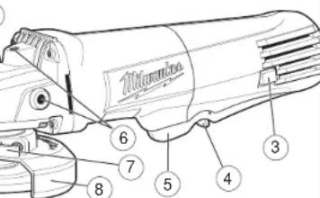
MISE A LA TERRE
natural_image
Line drawing of a hand using a power tool on a cutting board (no text or symbols)Aluminium-Zircone Bi-Cut
30
TIERRA
Para parar la herramienta, suelte el interruptor. Make sure the tool comes to a complete stop before laying the tool down.
natural_image
Line drawing of a hand using a power tool, no text or symbols presentUNITED STATES - MILWAUKEE Service
MILWAUKEE prides itself in producing a premium quality product that is NOTHING BUT HEAVY DUTY ^10 . Your satisfaction with our products is very important to us! If you encounter any problems with the operation of this tool, or you would like to locate the factory Service/Sales Support Branch or authorized service station nearest you, please call...
1-800-SAWDUST
(1.800.729.3878)
Monday-Friday
7:00 AM - 6:30 PM
Central Time
or visit our website at
www.milwaukeeetool.com
For service information, use the 'Service Center Search' icon found in the 'Parts & Service' section.
Additionally, we have a nationwide network of authorized Distributors ready to assist you with your tool and accessory needs. Check your "Yellow Pages" phone directory under "Tools-Electric" for the names & addresses of those nearest you or see the 'Where To Buy' section of our website.
Contact our Corporate After Sales Service Technical Support about ...
•Technical Questions
•Service/Repair Questions
•Warranty
call: 1-800-SAWDUST
fax: 1.800.638.9582
email: metproductsupport@milwaukeeetool.com
Register your tool online at www.milwaukeeetool.com and...
- receive important notifications regarding your purchase
- ensure that your tool is protected under the warranty
• become a HEAVY DUTY club member
Canada - Service MILWAUKEE
Milwaukee Electric Tool (Canada) Ltd
755 Progress Avenue
Scarborough, Ontario M1H 2W7
MILWAUKEE ELECTRIC TOOL CORPORATION
13135 West Lisbon Road • Brookfield, Wisconsin, U.S.A. 53005
58-14-1105d7 01/10
Printed in China
960931335-03(A)
- WORK AREA SAFETY
- ELECTRICAL SAFETY
- PERSONAL SAFETY
- POWER TOOL USE AND CARE
- SERVICE
- SPECIFIC SAFETY RULES
- Additional Safety Warnings
- FUNCTIONAL DESCRIPTION
- GROUNDING
- Grounded Tools: Tools with Three Prong Plugs
- Double Insulated Tools: Tools with Two Prong Plugs
- EXTENSION CORDS
- Guidelines for Using Extension Cords
- READ AND SAVE ALL INSTRUCTIONS FOR FUTURE USE.
- ASSEMBLY
- Installing Side Handle
- Installing/Removing Accessories
- OPERATION
- General Operation
- USING GRINDING WHEELS
- Grinding Wheel Selection
- Care of Grinding & Cut-Off Wheels
- Grinding
- USING CUT-OFF WHEELS
- USING WIRE BRUSHES
- USING SANDING DISCS
- Sanding Disc Selection
- Aluminum Oxide
- Aluminum Zirconia Bi-Cut
- Ceramic
- Installing Backing Pad and Sanding Discs
- Sanding
- Cross Sanding
- Removing Welds or Hammer Marks
- Finishing Metal
- Troubleshooting
- MAINTENANCE
- Maintaining Tools
- Cleaning
- Repairs
- ACCESSORIES
- LIMITED WARRANTY - USA AND CANADA
- LIMITED WARRANTY - MEXICO, CENTRAL AMERICA AND CARIBBEAN
- Procedure to make this warranty valid
- Exceptions
- MISE A LA TERRE
- Aluminium-Zircone Bi-Cut
- TIERRA
- UNITED STATES - MILWAUKEE Service
- 1-800-SAWDUST
- Register your tool online at www.milwaukeeetool.com and...
- Canada - Service MILWAUKEE
Brand : MILWAUKEE
Model : 6140-830
Category : Grinder