
VC-HU520BR - Car radio VIETA - Free user manual and instructions
Find the device manual for free VC-HU520BR VIETA in PDF.


| Product type | Car radio |
| Brand | Vieta |
| Model | VC-HU520BR |
| Dimensions (W x H x D) | 178 x 50 x 100 mm (standard 1 DIN) |
| Weight | 0.5 kg |
| Power supply | 12 V DC (vehicle battery) |
| Power consumption | 10 A max |
| Output power | 4 x 50 W max |
| Radio reception type | AM/FM stereo, RDS |
| Supported audio formats | MP3, WMA, WAV (via USB/SD) |
| Connectivity | Bluetooth (hands-free, streaming), USB, SD, 3.5 mm AUX input, RCA output |
| Main functions | AM/FM radio, USB/SD player, Bluetooth, sound calibration (bass/treble, balance, fader), remote control included |
| Display | Backlit LCD, frequency and information display |
| Maintenance and cleaning | Clean with a soft, dry cloth. Do not use abrasive cleaners or solvents. |
| Safety | Disconnect power before any intervention. Use only fuses of the same rating. |
| Spare parts and repairability | Contact Vieta after-sales service for spare parts. Repairs by a qualified technician. |
| Operating temperature | -10°C to +60°C |
| General information | 1 DIN car radio with Bluetooth, USB/SD playback and auxiliary input. Ideal for vehicles without modern audio system. |
Frequently Asked Questions - VC-HU520BR VIETA
User questions about VC-HU520BR VIETA
0 question about this device. Answer the ones you know or ask your own.
Ask a new question about this device
Download the instructions for your Car radio in PDF format for free! Find your manual VC-HU520BR - VIETA and take your electronic device back in hand. On this page are published all the documents necessary for the use of your device. VC-HU520BR by VIETA.
USER MANUAL VC-HU520BR VIETA

VC-HU520BR

Manual de usuario
Radio USB/SD

User Manual
USB/SD Radio

Manuel utilisateur
Radio USB/SD

Gerätehandbuch
USB/SD Radio

natural_image
Isometric line drawing of a 3D rectangular object with a curved top and side profile (no text or symbols)(1) Panel frontal;
(2) Aro de moldura exterior;
(3) Funda;
(4) Llave izq;
(5) Llave dcha.
natural_image
Illustration of a mechanical assembly with a bracket, plate, and tool (no text or symbols)natural_image
Simple line drawing of a mechanical component with an arrow indicating rotation (no text or symbols)FM1, FM2, FM3, MW, AM
- Agudos (a 10 kHz): ±10 dB
VIETA AUDIO S.A. guarantees its products for a period of 24 months. The guarantee period starts on the date of purchase of brand new products that have never been used by the first end user.
This guarantee covers any possible manufacturing flaws for any Vieta products sold on Spanish territory by authorised distributors. Vieta products acquired in other countries will be covered by the guarantee supplied by the local distributor.
This guarantee will only be valid when accompanied by an invoice for the product that includes the client's name, the distributor and the date of purchase. VIETA AUDIO S.A. agrees to repair any product with a problem occurring during normal use as detailed in the user's manual and when being used for the purpose for which it was designed.
The guarantee will not be extended because a component is changed or the product is replaced.
INCIDENTS THAT ARE EXEMPT FROM GUARANTEE:
-
The guarantee period exceeds the stipulated time.
-
When the product has been handled by centres or personnel that are not authorised by VIETA AUDIO S.A.
-
When the product has been damaged by incorrect handling or use for purposes other than those it is intended for and that are not contemplated in the user's manual, or when it has broken pieces, scratches, cracks, wear and tear, damage produced by particles of paint, sand, water or food within the unit..
-
This guarantee does not cover expenses or damages caused by transport.
-
Loss, robbery or accidents produced by fire, liquid, chemical substances, excessive heat, inadequate ventilation, vandalism, electrical storms, incorrect or excessive power supply, lightening, impact, other external forces, radiation.
-
Any additional cost related to installing or uninstalling the product.
-
Products purchased outside Spanish territory or from distributors that are not authorised.
-
The data contained on our products (photo files, music, digital support, etc.) are not covered by the guarantee under any circumstance; it is the client's responsibility to make back-up files before giving us the product. Likewise, any incorrect configuration or installation of software or incompatibility issues with hardware belonging to other equipment, including drivers and controllers.
-
Maintenance, repairs or parts replacement due to use and wear and tear.
-
Rechargeable and/or disposable batteries (life cycle depends on usage frequency).
-
Small faults or variations in the quality of the product that do not affect its value or the purpose for which it was created.
-
Negligence.
-
Accessories:
-
Plugs and cases.
- Connector cables.
- Headband.
- Eartip and sleeve kits.
-
Decorative finishes.
-
Any issue detected on receipt of the goods must be notified to customer care 902.367.607 or sat@vieta.es. In accordance with article 366 of trade law, VIETA AUDIO S.A. will not accept any claims regarding broken goods, impacts or missing packages 24 hours after the goods have been delivered.
Contents
Installation 16
DIN Front-Mount (Method A)....16
Installing the unit 16
Removing the unit 17
DIN Rear-Mount (Method B) 17
Using the detachable front panel 18
Wiring Connection 19
Operation 20
Location of keys 20
Basic operation 21
Switching on/off the unit 21
Faceplate release 21
Sound adjustment 21
System setting....21
Mute 21
Loudness....21
Set the clock 21
Display information....21
Equalization....21
Reset function 21
Mode selection 21
Auxiliary input 21
Radio operation 21
Selecting the frequency band 21
Selecting station 22
Automatic memory storing&program scanning 22
Mono/stereo 22
Station storing 22
Selecting tracks 22
Selecting directory up/down 22
Pausing playing 22
Previewing all tracks 22
Repeating the same track 22
Playing all tracks in random 22
Selecting tracks by AMS button....22
Display information 22
Memory Card operation 23
RBDS Operation 23
Specification....24
Trouble shooting 25
Installation
Notes
- Choose the mounting location where the unit will not interfere with the normal driving function of the driver.
- Before finally installing the unit, connect the wiring temporarily and make sure it is all connected up properly and the unit and the system work properly.
- Use only the parts included with the unit to ensure proper installation. The use of unauthorized parts can cause malfunctions.
- Consult with your nearest dealer if installation requires the drilling of holes or other modifications of the vehicle.
- Install the unit where it does not get in the driver's way and cannot injure the passenger if there is a sudden stop, like an emergency stop.
- Avoid installing the unit where it would be subject to high temperature, such as from direct sunlight, or from hot air, from the heater, or where it would be subject to dust, dirt or excessive vibration.
Din front/rear-mount
This unit can be properly installed either
from "Front" (conventional DIN Front-mount) or "Rear" (DIN Rear-mount installation, utilizing threaded screw holes at the sides
of the unit chassis). For details, refer to the following illustrated installation methods.
Take out screw before installation
Before installing the unit, please remove the two screws.
Din front-mount (Method A)
Installation Opening
This unit can be installed in any dashboard having an opening as shown below:

natural_image
3D wireframe diagram of a rectangular object with a curved top and side profile (no text or symbols)Installing the unit
Be sure you test all connections first, and then follow these steps to install the unit.
- Make sure the ignition is turned off, and then disconnect the cable from the vehicle battery's negative (-) terminal.
- Disconnect the wire harness and the antenna.
- Press the release button on the front panel and remove the control panel (see the steps of "removing the front panel").
- Lift the top of the outer trim ring then pull it out to remove it.
- The two supplied keys release tabs inside the unit's sleeve so you can remove it. Insert the keys as far as they will go (with the notches facing up) into the appropriate slots at the middle left and right sides of the unit. Then slide the sleeve off the back of the unit.
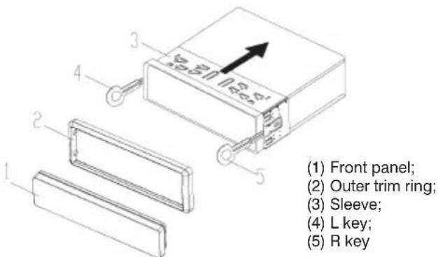
- Mount the sleeve by inserting it into the opening of the dashboard and bend open the tabs located around the sleeve with a screwdriver. Not all tabs will be able to make contact, so examine which ones will be most effective. Bending open the appropriate tabs behind the dashboard to secure the sleeve in place.

-
Reconnect the wire harness and the antenna and be careful not to pinch any wires or cables.
-
Slide the unit into the sleeve until it locks into place.
-
To further secure the unit, use the supplied metal strap to secure the back of the unit in place. Use the supplied hardware (Hex Nut (M5mm) and Spring Washer) to attach one end of the strap to the mounting bolt on the back of the unit. If necessary, bend the metal strap to fit your vehicle's mounting area. Then use the supplied hardware (Tapping Screw and Plain Washer) to attach the other end of metal strap to a solid metal part of the vehicle under the dashboard. This strap also helps ensure proper electrical grounding of the unit.
Note: Install the short threading terminal of the mounting bolt to the back of the unit and the other long threading terminal to the dashboard.

- Reconnect the cable to the vehicle battery's negative (-) terminal. Then replace the outer trim ring and install the unit's front panel (see the steps of "Installing the front panel").
Removing the unit
-
Make sure the ignition is turned off, then disconnect the cable from the vehicle battery's negative (-) terminal.
-
Remove the metal strap attached the back of the unit (if attached).
-
Press the release button to remove the front panel.
-
Lift the top of the outer trim ring then pull it out to remove it.
-
Insert both of the supplied keys into the slots at the middle left and right sides of the unit, then pull the unit out of the dashboard.

Din rear-mount (Method B)
If your vehicle is a Nissan, Toyota, follow these mounting instructions.
Use the screw holes marked T (Toyota), N (Nissan) located on both sides of the unit to fasten the unit to the factory radio mounting brackets supplied with your vehicle.

To fasten the unit to the factory radio mounting brackets.
Align the screw holes on the bracket with the screw holes on the unit, and then tighten the screws (5x5mm) on each side.
Note: the outer trim ring, sleeve and the metal strap are not used for method B installation.

natural_image
Illustration of a mechanical assembly with a rectangular block and a ruler, enclosed in a circular frame (no text or symbols)Using the detachable front panel
Removing the front panel
- Press the release button on the front panel and pull off the front panel.

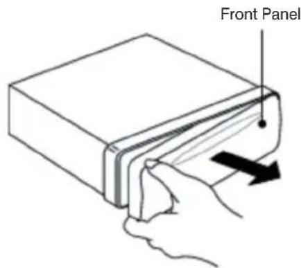
- Keep the control panel into the case.

Front Panel
Installing the front panel
To install the front panel, insert the panel into the housing and make sure the panel is properly installed. Otherwise, abnormality occurs on the display or some keys will not function properly.

natural_image
Line drawing of a mechanical component with an arrow indicating rotation (no text or symbols)Precautions when handling
- Do not drop the front panel.
- Do not put pressure on the display or control buttons when detaching or re-installing the front panel.
- Do not touch the contacts on the front panel or on the main unit body. It may result in poor electrical contact.
- If any dirt or foreign substances adhere to the contacts, they can be removed with a clean and dry cloth.
- Do not expose the front panel to high temperatures or direct sunlight.
- Keep away any volatile agents (e.g. benzene, thinner, or insecticides) from touching the surface of the front panel
- Do not attempt to disassemble the front panel.
Wiring Connection
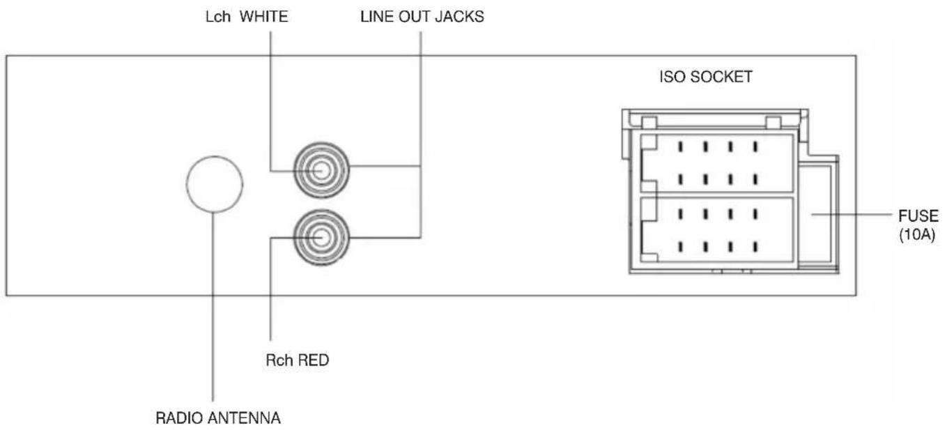

Connector A
- N.C
- N.C
- N.C
- MEMORY +12V (YELLOW)
- AUTO ANTENNA OUTPUT (BLUE)
- N.C
- +12V (TO IGNITION KEY) (RED)
- GROUND (BLACK)
Connector B
- REAR RIGHT SPEAKER (+) (VIOLET)
- REAR RIGHT SPEAKER (-) (VIOLET/BLACK)
- FRONT RIGHT SPEAKER (+) (GRAY)
- FRONT RIGHT SPEAKER (-) (GRAY/BLACK)
- FRONT LEFT SPEAKER (+) (WHITE)
- FRONT LEFT SPEAKER (-) (WHITE/BLACK)
- REAR LEFT SPEAKER (+) (GREEN)
- REAR LEFT SPEAKER (-) (GREEN/BLACK)
Operation
Location of Keys

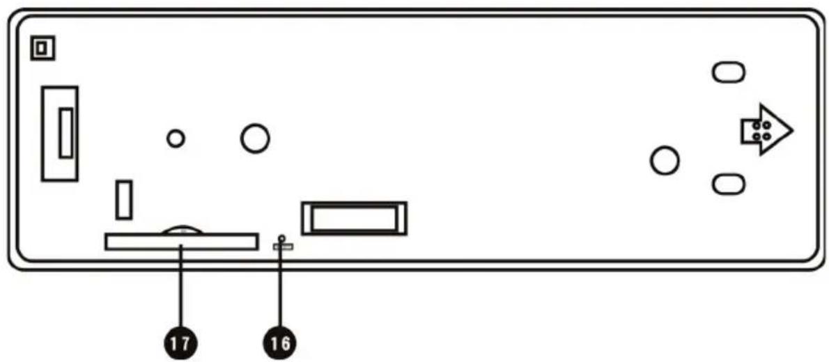
- Volume Buttons ▲ ▼ (SEL/MUNE)
- AUX IN
- ▲ (release button)
BND - LCD
- 5/DIR-
7.4/RDM - 1/PAU
- 2/INT
- MODE
11.3/RPT -
⏻ /MUTE
-
6/DIR+
- USB interface
- PTY/AF
- Reset button
- Memory Card interface
- DISP
- AMS
- MON
- EQ/TA
- ◀◀ / ▶▶ (tune/seek/track down/up buttons)
23.1-6 preset buttons
Basic Operation
SWITCHING ON/OFF THE UNIT
Press ⏻ button to turn on the unit, When the unit is on, press and hold ⏻ button to turn the unit off.
FACEPLATE RELEASE
Press button ▲ to detach the removable faceplate.
SOUND ADJUSTMENT
Shortly press Volume knob button to enter AUDIO SETTING mode, use Volume knob button to select the desired adjustment mode. The adjustment mode will change in the following order:
BAS, TRE, BAL, FAD
Use the volume knob to the left or right to Adjust the volume
SYSTEM SETTING
Press and hold the volume button (1) on the front panel to enter system setting mode. Then briefly press the volume button (1) to select the item you want to change and rotate the volume knob (1) to change the corresponding setting.
1) BEEP ON/OFF
Use to set Beep sound on or off.
2) P-VOL
Use Volume Up/Down button to select the volume level when the unit turns on.
3) AREA EUR/USA
Use Volume Up/Down button to set EUR or USA area frequency spacing.
MUTE
Shortly press MUTE button will mute the sound instantly, press it again will resume the sound.
LOUDNESS
Press LOU button for several seconds to switch loudness function on, and "LOUD" will appear on the LCD.
Press it for several seconds again to release this function, and "LOUD" will disappear.
SET THE CLOCK
Press the DISP button shortly until the clock is shown on the LCD display. Then hold down DISP button until the clock flashes. Then rotation the volume button to change minutes or to change hours.
DISPLAY INFORMATION
Press DISP button (18) to operate as the conversion of each display mode.
EQUALIZATION
Press EQ/TA button to turn on equalization function and to select desired audio mode. There are several kinds of mode as below:
FLAT, CLASSIC, POP, ROCK, EQ OFF
RESET FUNCTION
RESET button must be activated with either a ballpoint pen or thin metal object. The RESET button is to be activated for the following reasons:
- Initial installation of the unit when all wiring is completed.
- All the function buttons do not operate.
- Error symbol on the display.
Note: if press RESET button, the unit can't work yet, please use a cotton swab soaked in isopropyl alcohol to clean the socket on the front panel.
MODE SELECTION
Shortly press MODE button to select the desired mode, such as Radio, USB, CARD, AUX mode.
When there isn't an USB or CARD connected to the unit, the corresponding mode will be skipped.
AUXILIARY INPUT
The unit can be connected to a portable audio player through the AUX IN jack on the front panel. After finishing the connection, you can press MODE button on the front panel to switch the mode to AUX IN mode.
Radio Operation
At radio mode, press BND button shortly to select the desired band.
The reception band will change in the following order:
FM1, FM2, FM3, MW AM
SELECTING STATION
Shortly press ◀◀ ▶▶ buttons to activate automatic seek function. Press for several seconds until “MANUAL” appears on the display, the manual tuning mode is selected. If both buttons have not been pressed for several seconds, they will return to seek tuning mode and “AUTO” appears on the display then disappears.
AUTOMATIC MEMORY STORING & PROGRAM SCANNING
- Automatic memory storing
Press AMS button for several seconds "SEARCH" will appear on LCD.
the radio will search from the current frequency and checks the signal strength until one cycle search is finished. And then 6 strongest stations are stored into the corresponding preset number button.
- Program scanning
Press AMS button shortly to scan preset station. And the corresponding station number P1\~P6 will flash on LCD.
NOTE:
In MP3 playback mode, press the AMS key selections.
MONO/STEREO
Press MON button to select mono or stereo mode. You can sometimes improve reception of distant stations by selection mono operation.
STATION STORING
Press any one of the preset buttons (1 to 6) to select a station, which had been stored in the memory. Press this button for several seconds to store the current station into the number button.
USB Play Operation
In the front panel of the unit, there is an USB interface. You can connect an USB device through this interface.
When you connect an USB device through the interface, the unit will search the MP3 files or WMA files in the USB driver and start to play MP3 files or WMA files automatically.
If in other mode, you can also press MODE button to select USB mode.
SELECTING DIRECTORY UP/DOWN
Press DIR- button or DIR+ button to select directory downward or upward. If the MP3/WMA file does not contain any directory, there is no function of pressing DIR- button or DIR+ button.
PAUSING PLAYING
Press PAU button to pause the play. Press it again to resume play.
PREVIEWING TRACKS
Press INT button to play first several seconds of each track. Press again to stop intro and listen to track.
REPEATING THE SAME TRACK
Press RPT button to continuously repeat the same track. Press it again to stop repeat.
PLAYING TRACKS IN RANDOM
Press RDM button to play all tracks on the USB in random order. Press again to cancel the function.
SELECTING TRACKS BY AMS BUTTON
Press AMS button, then You can use the volume buttons to select the track directly.
Then press the VOLUME button or BND button to start playing the track.
DISPLAY INFORMATION
Press DISP button to show the following information, such as the clock, ID3 TAG (if available: song title, directory name, artist name, other contents...) (FOR WITH MP3 ID3 FUNCTION VERSION ONLY) and other information.
Note:
■ The main unit can only support the standard USB-memory device which is approved by Microsoft.
■ USB MP3 player is not a standard which means different brand name or different models have their own standard. So our product cannot support every MP3 player.
■ When connecting an MP3 player and there has normal battery in the player (non rechargeable battery), you should remove the battery from the MP3 player then connect it to the USB interface. Otherwise, it may cause battery burst.
■ When in USB play mode, be sure not to remove the USB driver from the USB interface.
Memory card operation
There is a memory card interface on the housing the unit.
When you insert a memory card in the memory card interface, the unit will search the MP3 files or WMA files in the card and start to play MP3 files or WMA files automatically.
The operation is the same with the USB operation described above.
CAUTION
When there are important files in the USB device or the memory card, do not connect it to the main unit to play. Because any wrong operation may cause files loss. And our company assumes no responsibility for this.
RBDS OPERATION
- Using PTY/AF to Select Program
■ Press PTY/AF button once to select the PTY group. Then rotate the volume knob to select the PTY program.
After selecting the PTY program the unit searches for the respective stations and stops when a station is found.
■ With PTY ON, press PTY/AF button again to cancel the PTY function.
- Listening to Traffic Announcement
Press and hold EQ/TA button, the unit will search Traffic Announcement automatically. Press and hold EQ/TA button. TA mode will exit.
Note: When selecting AREA EUR in system setting, hold press PTY/AF button to switch on or off RDS function. Whenever RDS is switch on, symbol "AF" appears on the display.
Specification
GENERAL
Power Supply Requirements: DC 12 Volts, Negative Ground
Tone Controls
- Bass (at 100 Hz): ±10 dB
- Treble (at 10 kHz): ±10 dB
Maximum Output Power: 4x25 watts
Current Drain: 10 Ampere (max.)
Signal to Noise Ratio: More than 55 dB
Channel Separation: More than 50 dB
Frequency Response: 40Hz – 18 kHz
RADIO
FM
Frequency Coverage: 87.5 to 108 MHz (Europe) 87.5 to 107.9 MHz (USA)
IF: 10,7 MHz
Sensitivity (S/N=30dB: 10 dBu
Stereo Separation: >25dB
AM
Frequency Coverage: 522 to 1620 KHz (Europe) 530 to 1710 KHz (USA)
IF: 450 kHz
Sensitivity (S/N=20dB): 36 dBu
Note: Specifications and design are subject to modification, without notice, due to improvements in technology.
Trouble Shooting
Before going through the checklist, check wiring connection. If any of the problems persist after checklist has been made, consult your nearest service dealer.
Symptom Cause Solution
| No power | The car ignition switch is not on. | If the power supply is connected to the car accessory circuits, but the engine is not moving, switch the ignition key to “ACC”. |
| The fuse is blown. | Replace the fuse. | |
| No sound | Volume is in minimum. Adjust volume to a desired level. | |
| Wiring is not properly connected. | Check wiring connection. | |
| The operation keys do not work | The built-in micro-computer is not operating properly due to noise. | Press the RESET button.Front panel is not properly fixed into its place. |
| The radio does not Work. The radio station automatic selection does not work. | The antenna cable is not connected. Insert the antenna cable firmly. | |
| The signals are too weak. Select a station manually. | ||
VIETA
CONDITIONS DE GARANTIE
natural_image
Isometric line drawing of a 3D rectangular object with hatched top surface and cutouts (no text or symbols)Installation de la radio
natural_image
Illustration of a mechanical assembly with a bracket, plate, and cylindrical component (no text or symbols)natural_image
Simple line drawing of a mechanical component with an arrow indicating rotation (no text or symbols)- ▲▼ Touches (SEL/MUNE)
- ENTRÉE AUX
- ▲ (Touche d'éjection)
- BND
- LCD
- 5/DIR-
- 4/RDM
- 1/PAU
- 2/INT
- MODE
11.3/RPT -
⏻ /MUTE
-
6/DIR+
- USB interface
- PTY/AF
- Touche de réinitialisation
- Interface de la carte mémoire
- DISP
- AMS
- MON
- EQ/TA
- / ▶ (Touches syntoniser/chercher/piste en bas)
23.1-6 Touches de préréglage
DIN FRONT-MOUNT (Methode A)....40
DIN Rear-Mount (Methode B) 41
natural_image
Isometric line drawing of a rectangular object with a curved top and side profile (no text or symbols)EINBAU DES GERÄTS
DIN REAR-MOUNT (METHODE B)
natural_image
Illustration of a mechanical assembly with a bracket, part of a ruler, and a rectangular plate (no text or symbols)BENUTZUNG DER ABNEHMBAREN FRONTPLATTE
ENTRIEGELN DER FRONTPLATTE
natural_image
Simple line drawing of a mechanical component with an arrow indicating rotation (no text or symbols)- VC-HU520BR
- INCIDENTS THAT ARE EXEMPT FROM GUARANTEE:
- Contents
- Installation
- Notes
- Din front/rear-mount
- Take out screw before installation
- Din front-mount (Method A)
- Installation Opening
- Installing the unit
- Removing the unit
- Din rear-mount (Method B)
- Using the detachable front panel
- Removing the front panel
- Installing the front panel
- Precautions when handling
- Wiring Connection
- Connector A
- Connector B
- Operation
- Basic Operation
- SWITCHING ON/OFF THE UNIT
- FACEPLATE RELEASE
- SOUND ADJUSTMENT
- SYSTEM SETTING
- MUTE
- LOUDNESS
- SET THE CLOCK
- DISPLAY INFORMATION
- EQUALIZATION
- RESET FUNCTION
- MODE SELECTION
- AUXILIARY INPUT
- Radio Operation
- SELECTING STATION
- AUTOMATIC MEMORY STORING & PROGRAM SCANNING
- MONO/STEREO
- STATION STORING
- USB Play Operation
- SELECTING DIRECTORY UP/DOWN
- PAUSING PLAYING
- PREVIEWING TRACKS
- REPEATING THE SAME TRACK
- PLAYING TRACKS IN RANDOM
- SELECTING TRACKS BY AMS BUTTON
- Memory card operation
- CAUTION
- RBDS OPERATION
- Specification
- GENERAL
- RADIO
- FM
- AM
- Trouble Shooting
- VIETA
- CONDITIONS DE GARANTIE
- Installation de la radio
- EINBAU DES GERÄTS
- DIN REAR-MOUNT (METHODE B)
- BENUTZUNG DER ABNEHMBAREN FRONTPLATTE
- ENTRIEGELN DER FRONTPLATTE
Brand : VIETA
Model : VC-HU520BR
Category : Car radio