
GW12756 - Motion detector Gewiss - Free user manual and instructions
Find the device manual for free GW12756 Gewiss in PDF.


| Product Type | Motion Detector |
| Brand | Gewiss |
| Model | GW12756 |
| Dimensions (L x H x D) | Approximately 10 x 7 x 5 cm |
| Weight | Approximately 150 g |
| Power Supply | 230 V AC, 50 Hz |
| Maximum Power | Up to 1000 W (resistive load) |
| Detection Angle | 180° |
| Detection Range | Up to 12 m (at 25°C) |
| Adjustable Timer | From 10 seconds to 15 minutes |
| Adjustable Twilight Threshold | From 3 to 2000 lux |
| Protection Rating | IP44 |
| Operating Temperature | -10°C to +40°C |
| Housing Material | UV-resistant plastic |
| Main Functions | Motion detection, automatic on/off, timer, sensitivity and light level adjustment |
| Maintenance and Cleaning | Clean with a soft, dry cloth. Do not use abrasive products or solvents. |
| Safety | Disconnect power before any intervention. Installation by a qualified electrician. |
| Spare Parts and Repairability | Sealed device, no user-replaceable parts. Contact Gewiss after-sales service. |
| General Information | Compliant with CE standards. Indoor/outdoor use under shelter. |
Frequently Asked Questions - GW12756 Gewiss
User questions about GW12756 Gewiss
0 question about this device. Answer the ones you know or ask your own.
Ask a new question about this device
Download the instructions for your Motion detector in PDF format for free! Find your manual GW12756 - Gewiss and take your electronic device back in hand. On this page are published all the documents necessary for the use of your device. GW12756 by Gewiss.
USER MANUAL GW12756 Gewiss
IR movement detector with Easy twilight switch - flush-mounted
natural_image
Exterior view of a modern KNX E13 digital camera with 'LUX TIME' branding (no additional text or symbols visible)GW 10 756 GW 12 756 GW 14 756
A
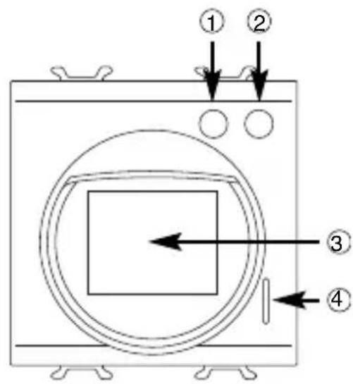

① Potenziometro regolazione sensibilità luminosa - Potentiometer to regulate light sensitivity - Potentiomètre de réglage de la sensibilité lumineuse - Potenciómetro regulación sensibilidad luminosa - Potentiometer Einstellung Helligkeitsempfindlichkeit
② Potenziometro regolazione periodo di trasmissione - Potentiometer to regulate transmission periods - Potentiomètre de réglage de la période d'émission - Potenciómetro regulación período de transmisión - Potentiometer Einstellung Übertragungsdauer
③ Sensori IR e crepuscolare - IR sensors and twilight switch - Capteurs IR et capteur crépusculaire - Sensores IR y crepuscular - IR-und Dämmerungssensoren
④ LED di rivelazione movimento - Movement detector LED - LED de détection de mouvement - LED de detección de movimiento - LED für Bewegungserfassung
⑤ LED di programmazione - Programming LED - LED de programmation - LED de programación - Programmier-LED
⑥ Tasto di programmazione - Programming key - Touche de programmation - Tecla de programación - Programmiertaste
⑦ Terminali bus - Bus terminal - Borniers bus - Terminales bus - Busanschlüsse
B

INDICE
PROGRAMMING WITH THE EASY BASE UNIT 21
FINE TUNING 22
IN SERVICE 23
TECHNICAL DATA 24
GENERAL INFORMATION
Warning! The safety of this appliance is only guaranteed if all the instructions given here are followed scrupulously. These should be read thoroughly and kept in a safe place. The Chorus products must be installed in compliance with the requisites of standard CEI 64-8 for devices for domestic use and similar, in non-dusty atmospheres and where special protection against water penetration is not required.
The GEWISS sales organisation is at your disposal for clarifications and technical information.
Gewiss SpA reserves the right to make changes to the product described in this manual at any time and without giving any notice.
Pack content
n. 1 IR movement detector with Easy twilight switch – flush mounted
n. 1 Bus terminal
n. 1 Cover with screw
n. 1 Installation and user manual
Summary
The movement detector with Easy twilight switch - flush-mounted allows you to send timed activation commands to actuator devices using the KNX/EIB bus through which it connects to the Home Automation system, according to the movements detected and the light measured by the two built-in sensors.
The passive Infra Red (IR) sensor has an adjustable lens with fixed opening.
The detector is powered by the bus line and is fitted with two potentiometers on the front, for local regulation of light sensitivity levels and the local variation of the transmission period (+/- 50% of the value set via the base unit), and a green indicator LED that signals movement detection and the consequential messages sent to the bus. The sensor can be configured using the Easy base unit (GW 90 831) to send timed activation commands. It is possible to set the functions on the device so that they activate only movement detection when the actuator to be commanded is ON (conditioned detection).
This function mode allows you, for instance, to switch on lights in the traditional manner (using a button or similar fitting) whilst guaranteeing the automatic switch-off function once the area covered by the movement sensors is liberated.
The device functions are inhibited for approx. 60 secs at switch-on, i.e. the time needed to stabilise the IR detector.
The device is fitted inside a standard flush-mounted box, mounted on Chorus supports in the space of two modules.
Functions
ACTIVATION WITH MOVEMENT AND TWILIGHT SWITCH
It sends a timed activation message to the KNX/EIB bus, for instance to turn a light on, when movement is detected in a specific area by IR sensors and, at the same time, when the environmental light is lower than the set value. Movement detection and the sending of the activation message is indicated by a brief flashing of the front green LED.
The "Transmission period", which can be customised, is the observation period activated each time an activation message is sent: if the IR sensor detects movement during this period, when the time expires a new activation message will be sent, regardless of the dimming value detected.
The device manages a safety intermission which excludes the IR sensor for 5 seconds when the commanded actuator switches OFF (it requires the commanded actuator to send its status information).
This intends to prevent undesired activation, for instance caused by the switching off of an electrical load with high heat emission.
It is also possible to only activate movement detection when the actuator to be commanded is ON (conditioned detection). This function mode allows you, for instance, to switch on lights in the traditional manner (using a button) and automatically switch them off when movement is no longer detected.
INSTALLATION

WARNING: the installation of the device must be exclusively done by qualified personnel, following the regulations in force and the guidelines for KNX/EIB installations.
Warnings for KNX/EIB installations
- The length of the bus line between the IR movement detector and the power supply unit must not exceed 350 metres.
- The length of the bus line between the IR movement detector and the most distant KNX/EIB device must not exceed 700 metres.
- If possible do not create ring circuits so as to prevent undesirable signals and overloads.
- Keep a distance of at least 4 mm between the individually insulated cables of the bus line and those of the electric line (figure C).
- Do not damage the electrical continuity conductor of the shielding (figure D).

WARNING: the unused bus signal cables and the electrical continuity conductor must never touch elements under power or the earth conductor!
Correct installation position
In order to function correctly, the detector must be installed at a distance from sources of heat, such as radiators, and must not be positioned in direct sunlight.
Electrical connections
Figure B shows the electrical connections diagram.
- Connect the bus cable's red wire to the terminal's red connector (+) and the black wire to the black connector (-). Up to 4 bus lines can be connected to the bus terminal (wires of the same colour in the same terminal) (figure E).
- Insulate the screen, the electrical continuity conductor and the remaining white and yellow wires of the bus cable (should a bus cable with 4 conductors be used), which are not needed (figure D).
- Insert the bus connector into the special feet of the device. The fastener guides determine the direction it should be inserted. Insulate the bus terminal using the relative cover, which must be screwed onto the device.
The cover guarantees that the power cables and the bus cables are separated by at least 4 mm (figure F).
Initialization with the Easy base unit
- Power up the device through the bus.
- Have the system acquire the device with one of the following procedures:
• Automatic acquisition (the device still has the factory settings):
- select the “Application → New function” or “Application → Edit function” menu in the Easy base unit: the device will be recognized automatically.
- Manual acquisition (the factory settings have been modified):
- select the "Application →Search device" menu in the Easy base unit;
- briefly press (< 2 seconds) the programming key. The programming LED will light up during the acquisition process (figure A).
The device acquired by the Easy base unit will be listed, with the number assigned, in the channels of the “Application → New function” or “Application → Edit function” menus.
Completing installation
Insert the device into a Chorus support, making sure the potentiometer edges are at the top.
Complete the installation with other Chorus devices or hole covers and fix it to the relative container (flush-mounted box, wall-mounted box, etc.).
Apply the finish plate.
PROGRAMMING WITH THE EASY BASE UNIT
Programming the device through the Easy base unit (code GW 90 831).
The device to be used in the function that is to be created can be selected at choice:
- locally by causing the detector to intervene: the corresponding channel will be highlighted in the channel list in the "Application → New function" or "Application → Edit function" menu;
- directly from the list of channels of the “Application →New function” or “Application →Edit function” menus.
| Names of the functions on the Easy base unit | |
| timer mode | command ON with timer(the time is set on the actuator) |
The function can be created after the device has been selected.
Refer to the Easy base unit documentation for further information on the programming procedures.
Configuration parameters (Easy)
After creating the desired function, it is possible to configure the device function parameters from the "Application → Parameters" menu.
The parameters available, in relation to the function created, are listed in the following table.
The underlined value is the default value.
| Function: timer mode | |
| Parameter: transmission period | |
| 10s | cycle time – 10 seconds |
| 30s | cycle time – 30 seconds |
| 45s | cycle time – 45 seconds |
| 1m | cycle time – 1 minute |
| 2m | cycle time – 2 minutes |
| 5m | cycle time – 5 minutes |
| Function: timer mode | |
| Parameter: keep move. applica. | |
| disabled enabled | conditioned detection deactivated conditioned detection activated |
Adjusting the intervention threshold on the twilight sensor
Rotate the detector's left potentiometer edge (Figure G) to set the minimum light level under which the device will send the activation message on detecting movement. The sensitivity increases by rotating the potentiometer counter clockwise and decreases by rotating it clockwise.
| potentiometer positioin | sensitivity |
| counter clockwise stroke end | 10 lux (nearly dark) |
| centre position | 80 lux |
| clockwise stroke end | exclusion of the twilight switch(just before the exclusion it reaches 500 lux) |
Manual regulation of the transmission period
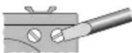
The transmission period set through the Easy base unit can be regulated manually by ± 50% rotating the right local potentiometer on the detector (Figure H). For instance, setting a time of 30 seconds on the Easy base unit, it will be possible to continuously regulate the transmission period from 15 to 45 seconds.
| Potentiometer position | regulation of the set transmission period |
| Counter clockwise stroke end | 50% (half the time set through the Easy base unit) |
| centre position | 100% (time set through the Easy base unit) |
| clockwise stroke end | 150% (1.5 times the time set through the Easy base unit) |
IN SERVICE
Behaviour on the failure and reinstatement of the bus power supply
When the bus power supply fails, the device performs no actions.
The device is in full operating mode after around 60 seconds from reinstatement of the bus power supply.
Maintenance
Always keep the front lens on the detector perfectly clean using a dry cloth. No other maintenance is required.
TECHNICAL DATA
| Communication | Bus KNX/EIB |
| Power Supply | By KNX/EIB, 29 V dc SELV bus |
| Bus cable | KNX/EIB TP1 |
| Bus current consumption | 5 mA max |
| Control elements | 1 mini programming key |
| Display elements | 1 red programming LED |
| 1 green signal LED | |
| Measuring elements | 1 PIR sensor ( = 5 ÷ 14 m ) |
| 1 twilight sensor (10÷500 lux) | |
| Configuration elements | 1 rotating potentiometer to regulate the twilight sensor, |
| 1 rotating potentiometer to regulate the transmission period | |
| IR sensor range | Max distance: 10m |
| Vertical range: 30° adjustable | |
| Horizontal range: 105° adjustable | |
| Ambit of use | Indoors, dry places |
| Operating temperature | -5 ÷ +45 °C |
| Storage temperature | -25 ÷ +70 °C |
| Relative humidity | Max 93% (no condensation) |
| Bus connection | 2-pin ∅ 1 mm plug connector |
| Protection rating | IP20 |
| Dimensions | 2 Chorus modules |
| Reference standards | Low Voltage Directive 2006/95/EC |
| Electromagnetic Compatibility Directive 89/336/EEC | |
| EN50428,EN50090-2-2 | |
| Certification | KNX/EIB |
TECHNICAL DATA

radar
| Distance (m) | Value | | ------------ | ----- | | 10 | 987654321 | | 2 | 10 | | 10 | 9876543 |HORIZONTAL RANGE ZONE

area
| x | y | | ---- | ----- | | 1 | 1 m | | 2 | 1 m | | 10 m | 1 m |VERTICAL RANGE ZONE
SOMMAIRE
page
AVERTISSEMENTS GENERAUX 28
DESCRIPTION GENERALE 29
INSTALLATION 31
PROGRAMMATION AVEC UNITE DE BASE EASY 33
MISE AU POINT 34
EN SERVICE 35
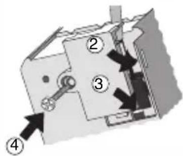
① Cavo bus - Bus cable - Câble bus - Cable bus - Buskabel
② Conduitore di continuità elettrica - Electrical continuity conductor - Conducteur de continuité électrique - Conductor de continuidad eléctrica - Stromdurchgangsleiter
③ Schermatura - Shielding - Blindage - Blindaje - Abschirmung
E

natural_image
Mechanical assembly diagram showing a piston and cylinder inside a housing (no text or symbols)G




10 lux 80 lux 500 lux/OFF
H



* 0.5 * 1 * 1.5


- INDICE
- GENERAL INFORMATION
- Pack content
- Summary
- Functions
- ACTIVATION WITH MOVEMENT AND TWILIGHT SWITCH
- INSTALLATION
- Warnings for KNX/EIB installations
- Correct installation position
- Electrical connections
- Initialization with the Easy base unit
- Completing installation
- PROGRAMMING WITH THE EASY BASE UNIT
- Configuration parameters (Easy)
- Adjusting the intervention threshold on the twilight sensor
- Manual regulation of the transmission period
- IN SERVICE
- Behaviour on the failure and reinstatement of the bus power supply
- Maintenance
- TECHNICAL DATA
- SOMMAIRE
Brand : Gewiss
Model : GW12756
Category : Motion detector