
Graphite 25 - MIDI Keyboard SAMSON - Free user manual and instructions
Find the device manual for free Graphite 25 SAMSON in PDF.


| Product Type | MIDI Keyboard Controller |
| Brand | Samson |
| Model | Graphite 25 |
| Number of Keys | 25 velocity-sensitive keys |
| Key Action | Synth action, non-weighted |
| Pitch Wheel | Yes |
| Modulation Wheel | Yes |
| Transport Controls | Play, Stop, Record, Rewind, Fast Forward |
| Assignable Knobs | 8 programmable knobs |
| Assignable Buttons | 8 programmable buttons |
| Octave Shift | Yes (up/down buttons) |
| MIDI Connectivity | USB-MIDI, 5-pin MIDI Out |
| USB Port | Type B |
| Power Supply | USB bus powered or optional DC 9V adapter |
| Dimensions (W x D x H) | 18.5 x 7.5 x 2.5 inches (47 x 19 x 6.4 cm) |
| Weight | 3.5 lbs (1.6 kg) |
| Compatibility | Windows, macOS, iOS (via Camera Connection Kit) |
| Included Software | Samson SoftAmp, Ableton Live Lite, other DAW demos |
| Maintenance | Clean with a dry, soft cloth; avoid liquids |
| Safety | Do not expose to moisture or extreme temperatures |
| Spare Parts & Repairability | Contact Samson support for replacement parts |
Frequently Asked Questions - Graphite 25 SAMSON
User questions about Graphite 25 SAMSON
0 question about this device. Answer the ones you know or ask your own.
Ask a new question about this device
Download the instructions for your MIDI Keyboard in PDF format for free! Find your manual Graphite 25 - SAMSON and take your electronic device back in hand. On this page are published all the documents necessary for the use of your device. Graphite 25 by SAMSON.
USER MANUAL Graphite 25 SAMSON
natural_image
Black and white photo of a Graphite 25 audio recorder with piano keyboard and control buttons (no visible text or symbols on the device body)OWNER'S MANUAL
SAMSON®
Copyright 2013 - Samson Technologies
V1.4
Samson Technologies
45 Gilpin Avenue
Hauppauge, New York 11788-8816
Phone: 1-800-3-SAMSON (1-800-372-6766)
Fax: 631-784-2201
www.samsontech.com
Native Instruments, NI and Komplete Elements are trademarks or registered trademarks of Native Instruments GmbH.
Important Safety Information

ATTENTION RISQUE D'ÉLECTROCUTION ! NE PAS OUVRIR !
CAUTION: TO REDUCE THE RISK OF ELECTRIC SHOCK, DO NOT REMOVE COVER (OR BACK). NO USER-SERVICEABLE PARTS INSIDE. REFER SERVICING TO QUALIFIED SERVICE PERSONNEL.
This lightning flash with arrowhead symbol within an equilateral triangle is intended to alert the user to the presence of non-insulated "dangerous voltage" within the product's enclosure that may be of sufficient magnitude to constitute a risk of electric shock.

The exclamation point within an equilateral triangle is intended to alert the user to the presence of important operating and maintenance instructions in the literature accompanying the appliance.
WARNING
TO PREVENT FIRE OR SHOCK HAZARD. DO NOT USE THIS PLUG WITH AN EXTENSION CORD, RECEPTACLE OR OTHER OUTLET UNLESS THE BLADES CAN BE FULLY INSERTED TO PREVENT BLADE EXPOSURE. TO PREVENT FIRE OR SHOCK HAZARD. DO NOT EXPOSE THIS APPLIANCE TO RAIN OR MOISTURE. TO PREVENT ELECTRICAL SHOCK, MATCH WIDE BLADE PLUG TO WIDE SLOT AND FULLY INSERT.
THIS DEVICE COMPLIES WITH PART 15 OF THE FCC RULES CLASS B. OPERATION IS SUBJECT TO THE FOLLOWING TWO CONDITIONS: (1) THIS DEVICE MUST NOT CAUSE HARMFUL INTERFERENCE, AND (2) THIS DEVICE MUST ACCEPT ANY INTERFERENCE RECEIVED INCLUDING INTERFERENCE THAT MAY CAUSE UNDESIRED OPERATION. SUITABLE FOR HOME OR OFFICE USE.
If you want to dispose this product, do not mix it with general household waste. There is a separate collection system for used electronic products in accordance with legislation that requires proper treatment, recovery and recycling.
Private household in the 25 member states of the EU, in Switzerland and Norway may return their used electronic products free of charge to designated collection facilities or to a retailer (if you purchase a similar new one).
For Countries not mentioned above, please contact your local authorities for a correct method of disposal. By doing so you will ensure that your disposed product undergoes the necessary treatment, recovery and recycling and thus prevent potential negative effects on the environment and human health.
CAUTION
Any changes or modifications to the construction of this device which are not expressly approved by the party responsible for compliance could void the user's authority to operate the equipment.
NOTE: This equipment has been tested and found to comply with the limits for a Class B digital device, pursuant to Part 15 of the FCC Rules. These limits are designed to provide reasonable protection against harmful interference in a residential installation. This equipment generates, uses, and can radiate radio frequency energy and, if not installed and used in accordance with the instructions, may cause harmful interference to radio communications. However, there is no guarantee that interference will not occur in a particular installation. If this equipment does cause harmful interference to radio or television reception, which can be determined by turning the equipment off and on, the user is encouraged to try to correct the interference by one or more of the following measures.
• Reorient or relocate the receiving antenna.
- Increase the separation between the equipment and receiver.
- Connect the equipment to an outlet on a circuit different from that to which the receiver is connected.
- Consult the dealer or an experienced radio/TV technician for help.
Important Safety Information
- Read these instructions.
- Keep these instructions.
- Heed all warnings.
- Follow all instructions.
- Do not use this apparatus near water.
-
Clean only with dry cloth.
-
Do not block any ventilation openings. Install in accordance with the manufacturer's instructions.
-
Do not install near any heat sources such as radiators, heat registers, stoves, or other apparatus (including amplifiers) that produce heat.
-
Only use attachments/accessories specified by the manufacturer.
-
Use only with the cart, stand, tripod, bracket, or table specified by the manufacturer, or sold with the apparatus. When a cart is used, use caution when moving the cart/apparatus combination to avoid injury from tip-over.

natural_image
Symbolic illustration of a person climbing a ladder inside a circle (no text or symbols)- Unplug the apparatus during lightning storms, or when unused for long periods of time.
- Refer all servicing to qualified personnel. Service is required when the apparatus has been damaged in any way, such as power supply cord or plug is damaged, liquid has been spilled or objects have fallen into the apparatus has been exposed to rain or moisture, does not operate normally, or has been dropped.
- This appliance shall not be exposed to dripping or splashing water and that no object filled with liquid such as vases shall be placed on the apparatus.
- Caution-to prevent electrical shock, match wide blade plug wide slot fully insert.
- Please keep a good ventilation environment around the entire unit.
- Always unplug cables by gripping the plug firmly, not by pulling on the cable.
Contents
Introduction. 7
Graphite 25 Features 8
System Components 8
Minimum System Requirements....8
Front Panel Controls and Functions 9
Rear Panel Controls and Functions 11
Quick Start. 12
Display Features 13
Graphite 25 Modes 14
Remote Control Presets 15
Preset Mode. 16
Setup Mode 17
Zones 20
Performance Mode Parameters 22
Performance Controls. 24
MIDI OUT. 26
Operational Flow Chart. 27
MIDI Continuous Controller (CC) List 28
Factory Default Settings 31
MIDI Note Numbers....33
Specifications.... 34
Introduction
Thank you for purchasing the Samson Graphite 25, 25-key USB keyboard controller! The Graphite 25 gives you all the performance and production control to easily integrate with your Windows or Mac digital production workstation. To capture the dynamics of your performance, the Graphite 25 comes equipped with a 25-key velocity-sensitive keyboard with aftertouch. In addition, the Graphite 25 has four velocity-sensitive trigger pads with aftertouch, that can be used for recording drum beats, triggering samples, or controlling midi parameters.
The Graphite 25 also functions as a full-featured control surface with eight encoders, four function buttons, one master slider, 16 function buttons, and transport controls. At the center of the keyboard, a large backlit LCD screen displays functions and accessible parameters in real-time, allowing you to make changes quickly without interrupting your performance or session.
The Graphite 25 is the perfect addition to your DAW or controlling virtual instrument software. To get you started making music immediately, we have included Native Instruments Komplete Elements, which contains over 1000 sounds and effects.
In these pages, you'll find a detailed description of the features of the Graphite 25 keyboard controller, as well as a guided tour of its control panel, and instructions for setup and use. You'll also find a warranty card enclosed. Please don't forget to fill it out and mail it in so that you can receive online technical support, and so that we can send you updated information about these and other Samson products in the future.
We recommend you record your serial number in the space provided below, for future reference.
Serial number: ____
Date of purchase: ____
With proper care and maintenance, your Graphite 25 will operate trouble-free for many years. Should your keyboard ever require servicing, a Return Authorization (RA) number must be obtained before shipping your unit to Samson. Without this number, the unit will not be accepted. Please call Samson at 1-800-3SAMSON (1-800-372-6766) for an RA number prior to shipping your unit. Please retain the original packing materials and, if possible, return the unit in its original carton. If your Graphite 25 was purchased outside of the United States, contact your local distributor for warranty details and service information.
Also, be sure to check out our website (www.samsontech.com) for Graphite desktop editing software, firmware updates, and remote control setup documentation.
Graphite 25 Features
The Samson Graphite 25 utilizes state-of-the-art technology and is engineered to the finest detail. Here are some of its main features:
• 25-key semi-weighted keyboard with aftertouch
- One programmable slider, eight encoders, and four buttons for hands-on control over your DAW and virtual instruments
- Four velocity-sensitive trigger pads with aftertouch (two banks each) for drum sounds and samples
• Large backlit LCD display provides real-time feedback
• MIDI Out, USB and sustain pedal connections
- Compact design, perfect for live performance and studio applications
• Dedicated Transpose and Octave buttons, Pitch Bend and Modulation wheels
• Three zones for creating splits and layering sounds
- Adjustable velocity curve for both keys and pads
- USB bus power
• Includes Native Instruments Komplete Elements software
System Components
• Samson Graphite 25 USB Keyboard
• One (1) USB Cable
• Native Instruments Komplete Elements installation DVD
• Graphite 25 Owner's Manual
Minimum System Requirements
Windows (PC)
• Windows XP/Vista/Win7
• 800MHz or higher, 256MB RAM or larger, USB port
Mac OS
• Mac OS X 10.4.9 or higher
• 733MHz or higher, 512MB RAM or larger, USB port
Front Panel Controls and Functions

-
Display - The backlit LCD is the command center for the Graphite 25. It displays the current setup information, performance data, adjustable parameters and controller information.
-
PAGE ◀ / ▶ Buttons - Press the PAGE buttons to navigate through the adjustable parameters and functions in all modes.
-
DATA +/- Buttons - Press the DATA buttons to adjust MIDI, controller, and performance data in all modes.
-
ENTER Button - When pressed, this button applies the selected parameter settings.
-
SETUP Button - Press this backlit button to enter Setup Mode to adjust and assign performance and controller parameters within a preset.
-
ZONE Button - Press this backlit button to edit the three zones from which the Graphite can send independent note and controller information.
-
PRESET Button - Press this backlit button to enter Preset Mode, where you can select from 30 different software and user presets.
-
MAIN Button - Press this backlit button to enter Performance Mode. It will also cancel any adjusted parameters that have not been saved.
-
CHANNEL ◀ / ▶ Buttons - When preset No. 1 or any User preset is selected, pressing the CHANNEL buttons will shift the eight encoders and four function buttons by one MIDI channel to expand the working range of the controllers. When a software control preset is selected, the channel command is processed by the software.
-
BANK ◀ / ▶ Buttons - When preset No. 1 or any User preset is selected, pressing the BANK buttons will shift the eight encoders and four function buttons through four banks, allowing 48 individual parameters to be assigned. When a software control preset is selected, the channel command is processed by the software.
-
Assignable Encoders - The eight endless encoders send continuous control data via the USB or MIDI OUT jacks. The encoders E1–E4 are preset from the factory to send MIDI pan messages on channels 1–4; the encoders E5–E8 are preset from the factory to send volume messages on channels 1–4. The encoders can be assigned to control different parameters in Setup Mode.
-
Function Buttons - The four function buttons can be used to send MIDI note or control information, and can be set as either toggle or momentary style buttons. The current state of each button is shown on the display.
Front Panel Controls and Functions
- Trigger Pads - The four velocity-sensitive trigger pads can be assigned to send MIDI note or control information, and can be set as either toggle or momentary style buttons. For added control, these pads feature four velocity curves as well as aftertouch.
- PAD A/B Button - The Trigger Pads are configured into two pad banks, with different settings configured to each pad. Press the PAD A/B button to toggle between the two banks.
- Transport Buttons - The five transport buttons control universal Rewind, Fast Forward, Stop, Play and Record functions (respectively) in the factory default setting. They can also be assigned to control different parameters in the Setup Mode, similar to the Function Buttons. If you encounter a stuck (hanging) note, press the Rewind and Fast Forward buttons together to send a Panic command to all ports and channels. The Panic command includes "all notes off," "reset all controllers," "reset pitch bend" and "reset GM" system messages.
- OCTAVE +/- Buttons - Press the OCTAVE buttons to shift the octave of the keyboard up or down a maximum of four octaves, to extend the range of the keyboard. Each time you press the OCTAVE button, the range of the keyboard shifts up or down 12 notes.
- TRANSPOSE +/- Buttons - Press the TRANSPOSE buttons to shift the range of the keyboard up or down a maximum of 12 semitones (half-steps).
- PITCH BEND Wheel - Use this wheel to raise or lower the pitch of notes played on the keyboard.
- MODULATION Wheel - This wheel is usually used to add vibrato or other expressive effects to a sound being played.
- Master Volume Slider - This slider sends continuous control data via the USB or MIDI OUT jacks. The Master Volume slider is preset from the factory to control the master volume control. The slider can be assigned to control different parameters in Setup Mode.
- Function Keys - In Setup Mode, the first 18 keys of the keyboard are assigned to functions, and numerical digits (0–9).
Rear Panel Controls and Functions

- POWER Switch - Use this switch to turn the keyboard on or off.
- DC IN - The Graphite 25 can be powered using a 9V 300mA adaptor, connected to the DC IN jack.
- USB Connection - Connect a standard USB cable from this port to the USB connection on a computer or iPad to provide power to the keyboard, as well as to send and receive MIDI data.
- MIDI OUT - Use a 5-pin MIDI cable to connect the Graphite 25 to an external MIDI device.
- SUSTAIN Pedal Input - Connect a 1/4" sustain pedal to this input. This input is preset from the factory to send MIDI sustain (CC #64) messages. The SUSTAIN pedal input can be assigned to send different MIDI parameters in Setup Mode.
Quick Start
-
Connect the Graphite 25 to your computer using the supplied USB cable. The unit will receive power and transmit MIDI data via the USB connection.
-
Connect a 14 " TS pedal to the SUSTAIN pedal input.

-
Push the POWER switch to the on position.
-
Launch your DAW or virtual instrument software, and set the Graphite 25 as the MIDI Input and MIDI Output device.
-
To use the Graphite 25 with an external MIDI device (such as a sound module), connect a 5-pin MIDI cable to the MIDI OUT on the rear of the Graphite 25, and to the MIDI IN of the external device. For more information on connecting to an external MIDI device, please see "MIDI OUT" on page 26.
Display Features
The Graphite 25 features a backlit LCD screen that displays performance and status information.

Data - The current value of a given controller.
Operation - When a component is activated, the component name and operation data will be shown. If more than one component is activated at the same time, the display shows the information of the component that was most recently activated.
Preset - The current preset number. The range is 01–30.
Parameter Tags
Oct - Octave shift for the keyboard. The range is +/- 4.
Trans - Transpose shift for the keyboard. The range is +/- 12.
Bank - The bank is the collection of all encoders and function buttons set when the selected preset is "01" or User preset. The range is 1–4. When remote control preset is selected, it will display "-"
Ch+/- - Displays the transmitting MIDI Channel of the encoders and function buttons.
Zone - The number of the activated zones. The range is 1–3 .
Status Indicators
Local - This sign will appear when the Local function is engaged.
Mute - This sign will appear when the Mute function is engaged.
A/B - Indicates the active pad bank.
Button Indicators
F1-F16 - When a function button is at On status, the corresponding block will appear.
Trigger Pads - When a pad is pressed, the corresponding block will appear.
Transport Controls - When a transport button is on, the corresponding block will appear.
Graphite 25 Modes
The Graphite 25 has four main operation modes: Performance Mode, Preset Mode, Setup Mode and Zone Mode.
Preset Mode - In this mode, you can access the 30 available presets. A preset stores information on the assignments for the slider, knobs, and buttons. Using presets allows you to quickly load the settings for specific applications without having to reprogram the unit every time. This mode is activated by pressing the PRESET button. Refer to the section "Preset Mode" on page 16 for more details.
Setup Mode - In this mode, you can access and assign all of the features of the Graphite 25. This allows you to customize the settings to match your needs. In addition to the buttons on the top panel, the first 18 keys on the keyboard are also available to access functions and enter numerical data. This mode is activated by pressing the SETUP button. Refer to the section "Setup Mode" on page 17 for details.
Zone Mode - The keyboard can be divided into several zones, sometimes referred to as layers or splits. Each zone has its own active key range, program number, MSB and LSB, and can be set to transmit to different channels and ports. There are three zones available. Refer to the section "Zones Mode" on page 20 for more details.
Performance Mode - In this mode, the 25 velocity-sensitive keys transmit note and velocity information via the USB or MIDI output. The assignable controllers, pitch bend and modulation wheels all transmit continuous controller information. This mode is activated by pressing the MAIN button. Refer to the section "Performance Mode" on page 22 for details.
Remote Control Presets
The Graphite keyboard can be used as a control surface for most audio software titles. Along with presets that can be customized to tailor the keyboard to your work environment, the Graphite 25 comes with presets for many popular audio programs. Please refer to the section "Preset Mode" on page 16 for direction on how to call a remote control preset.
The Graphite 25 utilizes virtual MIDI Out Port 5 and In Port B with the Mackie Control protocol to communicate to the software. Specific control messages and data for the encoders, buttons, and slider depend on the selected remote control preset.

flowchart
graph TD
    A["USB VIRTUAL PORT"] --> B["Local"]
    B --> C["USB"]
    C --> D["COMPUTER"]
    style A fill:#f9f,stroke:#333
    style D fill:#ccf,stroke:#333
Within the audio software preferences, Mackie Control should be selected in the Control Surface settings. For some software titles, the MIDI control input will need to be set to SAMSON Graphite 25 (Controller).

Example from Ableton Live 8
Preset Mode
To select a preset, press the PRESET button and the keyboard will enter Preset Mode. The Preset indicator will light red, and the Preset number will flash under the PRESET tag. While in PRESET mode, the Graphite 25 will stop transmitting MIDI messages.
Use the DATA +/- buttons or numerical keys to select the desired Preset. The name of the Preset will appear in the
first row of the display. Press the ENTER button to confirm your choice, and the keyboard will load the new Preset settings for all slider, knobs and buttons. Pressing the MAIN button will cancel the selection and return to the previous Preset. There are 3 categories of presets:

GRAPHITE Preset
Preset 1 is configured for the Master Volume slider to control the master volume, and the encoders to control channel pan and volume for four channels at a time in Zone 1. Using this preset will get you started working with almost any standalone USB/MIDI device or audio software.
You can edit the Preset for each component in Setup Mode, and save your changes. The settings for Master Volume slider, encoders E1–E8 and function buttons F1–F4 can be organized into four banks, which can be accessed by pressing the BANK ◀ or ▶ buttons. The active MIDI channels for all encoders can be shifted up or down by one channel by pressing the CHANNEL ◀ or ▶ buttons.
Remote Control Presets
Presets 2–16 are designed for specific software titles, with the controls set to access the most common functions directly from the Graphite 25. The communication between the computer and the keyboard is bidirectional, and information from the software will appear on the Graphite's display. You can edit the Presets in Setup Mode and save your changes to further customize the parameters to suit your needs.
The Master Volume slider is used for master volume control. Encoders E1–E4 are used for channel pan control; E5–E8 are used for channel volume control. F1–F4 are used for channel Record for all software. The BANK and CHANNEL buttons are used to change the channels controlled within the software. The remote control message is sent through output Port 5 to the computer, and the message from the computer is received through input Port B of the keyboard.
Note: When you move the master volume slider on the computer, its data will be sent to the keyboard in real time, and it will be shown on the display, but it cannot affect the physical position of the slider on the keyboard. When you move the Master Volume slider on the keyboard, the message will not be transmitted until it reaches the value and position of the slider in the software. This eliminates any unexpected level jumps when the slider is moved.
User Presets
Presets 17–30 are User presets that can be fully customized to create your layout. The default settings for each User preset is the same as in Preset 1.
The User Preset also includes information about the contents of settings, for all zones, and activity status. Zone edit results are saved to the current activated Preset automatically.
Setup Mode
Setup Mode enables you to make adjustments to how the Graphite 25 will operate. Pressing the SETUP button will enter Setup Mode, the keyboard will stop transmitting MIDI data, and the first 18 keys will serve as numerical input and access to additional functions.
Controllers
To adjust a controller, press a button, move a slider or encoder, or press the pedal, and its name and parameter values will appear on the display.
Press the PAGE ◀ / ▶ buttons to cycle through the available parameters (see table below). The parameter name will be displayed and the value will flash. Use the DATA +/- buttons or numerical keys to set the appropriate value.

Note: When the value Ch is set to “-”, the controller follows the keyboard channel in Zone 1. You can use the DATA button to select “-”, or press the 0 key on the keyboard to select “-”.
Press the ENTER button or the ENTER key on the keyboard to confirm a selection. You can confirm the selection after each parameter, or after you finish editing all parameters for a controller. The new values will be saved and updated on the display.
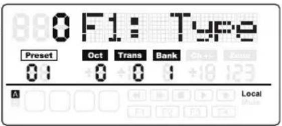
Note: The encoder settings are saved into the current activated bank. Press the BANK ◀ I ▶ to change the bank where the settings will be saved.
If you select another controller, or press the SETUP or MAIN buttons before saving your changes, your changes will be lost. Simultaneously pressing the DATA + and DATA – buttons will restore the controller to its original setting.
The setting of the slider, encoders and transport buttons cannot be changed in the Remote Control Preset. The components assigned to the function buttons vary according to the software title you are using.
| Parameter Controller Data Remark | |||
| Type Button or Pad 0: Control | 1: Note | ||
| Mode Button or Pad 0: Toggle | 1: Momentary | ||
| Ctrl or Note Button or Pad Control | 0–171 (ex-cept 152 and 153)Note: 0–127 | Depending on Type selection | |
| Ctrl Encoder or Slider 0–171 Refer to MIDI Continuous Controller | List in the back of the manual | ||
| Port | All | 1–5 | Transmitting Port |
| Ch [1] | All | 1–16 | Transmitting Channel |
[1] To set the controllers to follow the keyboard channel in Zone 1, press the 0 key, or use the DATA buttons to select "--" on the display.
Setup Mode
Editing the Aftertouch Control
Press the Aftertouch key to assign control code for the keyboard aftertouch feature. "A.Touch" will appear on the display with the value of the current control in the data area. Use the DATA +/- buttons to change the value, or enter data by pressing the numerical keys on the keyboard. Press both DATA +/- buttons simultaneously to recover the original value. Press the ENTER key or the ENTER button to confirm your setting and to save. When you save your settings, the value display will stop blinking.
Selecting the Keyboard Velocity Curve
Press the KB Vel key to select a velocity curve for keyboard. "KB.Curve" will appear in the Operation area of the display with its current velocity curve number in the data area. The Operation area will then change to show the current velocity curve. Use the DATA +/- buttons or enter the number by pressing the numerical keys on the keyboard to select a curve. Press the ENTER key or the ENTER button to confirm your setting and to save. When you save your settings, the name of the velocity curve will be updated, and the value display will stop blinking.
Available Velocity Curves
| No. Type Description | |
| 0 Normal Linear type curve - Default | |
| 1 Soft 1 Results in a lower transmitted velocity (and corresponding volume) | |
| 2 Soft 2 Results in a lower transmitted velocity (and corresponding volume) | |
| 3 Hard 1 Results in a higher transmitted velocity (and corresponding volume) | |
| 4 Hard 2 Results in a higher transmitted velocity (and corresponding volume) | |
| 5 Expand Emphasizing the louder volume and softening the lower volume | |
| 6 Compress Emphasizing the softer volume and softening the louder volume | |
| 7 Fix 64 Note velocity is fixed to 64 | |
| 8 Fix 100 Note velocity is fixed to 100 | |
| 9 Fix 127 Note velocity is fixed to 127 |

Setup Mode
Selecting Velocity Curve for the Trigger Pads
Press the Pad Vel key to select a velocity curve for the trigger pads. "P.Curve" will appear in the Operation area of the display with its current velocity curve number in the data area. The Operation area will then change to show the current velocity curve. Use the DATA +/- buttons or enter the number by pressing the numerical keys on the keyboard. Press the ENTER key or the ENTER button to confirm your setting and save it. The name of the velocity curve will be updated. The value display will stop blinking. Selectable curves are the same as keyboard velocity curves.
Switch the Local Control
The USB out from port 1 or 2 can be transmitted through the MIDI Out jack. This is controlled by the local setting. Press the Local key to switch the local control On/Off. "Local" and its current status will appear in the Operation area of the display, and flash. Press the DATA + (or numerical key 1) to turn Local Control on and DATA – (or numerical key 0) to turn Local Control off. Press the ENTER key or the ENTER button to confirm your setting and save it. When local is on, "Local" will appear in the Status Indicator area on the right side of the screen.
Pedal Setup
Press the pedal to assign a control code for the pedal. "Pedal" will appear in the Operation area of the display with the value of the current control in the data area. The value is also shown and will blink under the Val tag on the second row of the display. Use the DATA +/- buttons to change the value or enter the data by pressing the numerical keys on the keyboard. Press the ENTER key or the ENTER button to confirm your setting and save it. The value display will stop blinking.
Preset Reset
Press the Preset key to reset to the factory default setting. "Reset No" will appear in the Operation area of the display and "No" will blink. Press DATA + (or numerical key 1) to switch it to "Yes" or DATA – (or numerical key 0) to switch it "No." Press the ENTER key or the ENTER button to confirm your decision. When the Yes is confirmed, the Reset sign will appear in the Status Indicator area on the right side of the screen and "Loading..." will appear in the Operation area of the display. After the reset is finished, the display will show "Reset OK".
Mute Control
Messages for the operations of the encoders and slider are normally transmitted immediately with movement of the controller. You can set the Graphite so that it transmits all encoder and slider movements simultaneously. This is controlled by the MUTE setting. Press the Mute key to switch the mute control On/Off. "Mute" and its current status will appear in the Operation area of the display and flash. Press DATA + (or numerical key 1) to turn Mute Control on and DATA – (or numerical key 0) to turn Mute Control off. Press the ENTER key or the ENTER button to confirm your setting. When mute is on, "Mute" will appear in the Status Indicator area on the right side of the screen.
Zones Mode
The keyboard can be divided into three zones, sometimes referred to as layers or splits. Each zone has its own active key range, program number, MSB, LSB, Channel, Port, Octave, and Transpose settings. The zones can be separated or overlapped. This allows you to layer or split the keyboard between sounds to expand your performance. Zone 1 is always active. Zones 2–3 can be activated or disabled in Zone Mode. The display shows the parameters of the selected zone. The factory default is Zone 1.
Press the ZONE button to enter Zone Mode. The corresponding indicator will light up. Press the PAGE button to select a zone. The On/Off status appears after the zone number. Press the DATA+ button to engage the zone, and DATA- button to disable the zone. When a zone is activated, the zone number will appear under the Zone tag in the third row of the display. For each zone (1–3), the factory default MIDI Out port is 1–3, respectively. Press the MAIN button to return to Performance Mode.
If zones are activated and overlapped, keys played in the overlap section will send messages to multiple outputs and more than one voice can be produced. The PITCH BEND wheel, MODULATION wheel, pedal and keyboard aftertouch are applied to all activated zones.
Note: In Performance Mode, the operation of the OCTAVE +/- and TRANSPOSE +/- buttons only affect Zone 1, even if multiple zones are activated.
Editing Zones
After selecting a zone, press the ENTER button to edit the zone. Press the PAGE ◀ / ▶ buttons to cycle through the available parameters. Use the DATA +/- buttons or numerical keys to change the value of a parameter. Press both DATA +/- buttons simultaneously to return to the original value. When you have completed editing the zones, press the ENTER button or the ENTER key on the keyboard to save your changes.
Zone settings are nonvolatile, and will be saved even when the power is turned off. You can recover the default Zone settings with the PRESET function. Press the MAIN or ZONE button to exit Zone Mode and return to Performance Mode. To cancel your changes, before pressing Enter, press the MAIN or ZONE button to return to Performance Mode.
Note: Zones are saved to the current active Preset.
Note: In Performance Mode, changing the program number, MSB, LSB, Port and Channel only affect Zone 1. Enter Zone Mode to adjust the parameters of the other active zones.
Zones Mode
Available parameters in Zone Mode:
| Parameter D | Description Range | |
| Zn: Prog [1] | Program number for playing on the specific section of the keyboard [2] | 0–127 |
| Zn: MSB Most | Significant Bit of the program bank for playing on the specific section of the keyboard | 0–127 |
| Zn: LSB Least | Significant Bit of program bank for playing on the specific section of the keyboard | 0–127 |
| Zn: Port Transmitting port 1–5 | ||
| Zn: Ch Transmitting channel - the channel always follows the channel of Zone 1 if set to “-” | 1–16 | |
| Zn: Rang< Note number of the most left key in the specific section of the keyboard [3] | 0–127 | |
| Zn: Rang> Note number of the most right key in the specific section of the keyboard. [3] | 0–127 | |
| Zn: Oct Octave shift for the specific section of the keyboard. [4] -4–0–4 | ||
| Zn: Trans | Transpose for the specific section of the keyboard. [5] | -12–0–12 |
[1] "n" represents zone number
[2] If you set different programs in different zones with the same port and channel, it will cause a conflict, and the unit will use the program of the last activated zone.
[3] Press a key on the keyboard to set the beginning and end key of the range. If the end key is lower than beginning key, the entry will be rejected.
[4] Use the OCTAVE +/- buttons to change the octave shift.
[5] Use the TRANSPOSE +/- buttons to change the transpose.
Performance Mode
Octave Buttons
The Octave buttons allow you to shift the octave of the keyboard up or down to extend the range of the keyboard. Press the OCTAVE +/- buttons to shift the octave up or down a maximum of four octaves. Press the OCTAVE +/- buttons together to reset the octave shift to zero. The octave shift value will be shown under the Oct tag on the second row of the screen.
Note: This adjustment is only for Zone 1 in the current Preset. If you engage zones 2–4 or select another Preset, the octave shift value will change according to the setting in the zone. Please refer to the section "Zones Mode" on page 20 for more information.
Transpose Buttons
Press the TRANSPOSE +/- buttons to transpose a note up or down by a maximum of 12 semitones. Press the TRANSPOSE +/- buttons together to reset the transpose shift to zero. The transpose value will be shown under the Trans tag on the second row of the screen.
Note: This adjustment is only for Zone 1 in the current Preset. If you engage zones 2–4 or select another Preset, the transpose value will change according to the setting in the zone. Please refer to the section "Zones Mode" on page 20 for more information.
Aftertouch
The keyboard features aftertouch. After hitting a key, keep pressure on the key, and the channel aftertouch (value common to all keys) message will be transmitted. You can change the control of the aftertouch in Setup Mode (p. 17). The transmitting port and channel follow the port and channel settings of Zone 1.
Velocity Curve
The keyboard is velocity sensitive. There are ten selectable velocity curves. Refer to Selecting the Keyboard Velocity Curve on p. 18 to understand how to select a curve.
Modulation Wheel
The MODULATION wheel is usually used to add vibrato effects to tones you are playing. The data range of the MODULATION wheel is 0–127. The transmitting port and channel follow the port and channel settings of Zone 1.
PITCH BEND Wheel
The PITCH BEND wheel is used to bend notes played on the keyboard by raising or lowering the pitch. The response and range of the controller is based on the patch or sound source that is being controlled. The pitch bend wheel is spring-mounted and will return to the center position when it is released.
Pedal
The default setting for the pedal input is sustain. You can assign another control to the pedal in the Setup Mode. The transmitting port and channel follow the port and channel settings of Zone 1. Refer to the section "Pedal Setup" on page 19 to learn how to assign the pedal.
Note: Do not step on the pedal when powering on the keyboard. The unit will detect the polarity of the pedal automatically.
Performance Mode Parameters
Trigger Pads
The keyboard features four assignable velocity-sensitive trigger pads with aftertouch. The factory setting for the trigger pads is to function as drum pads. When you strike a pad, a corresponding icon will appear, and its note MIDI message will be transmitted on channel 10. The pad number and the velocity curve number will be shown in the Operation and Data area of the display and the port, channel, pad type, pad mode and note number information will be shown under their respective tags. When you continuously press a pad, it will send a channel aftertouch message, depending on how hard it is pressed.
The pads are configured to two pad banks with different settings for each pad, for a total of eight individual pads. Press the PAD A/B button to switch between the two banks. The active bank will be shown on the display. The factory default settings for pads are listed in the "Factory Default Settings" on page 31. You can select the pad velocity curve, change parameters, or assign other controls to pads in Setup Mode.
Setting the Channel, Program, MSB, LSB and Port for the Keyboard
Some parameters can be edited from Performance Mode. Press the PAGE ◀ / ▶ buttons to cycle through the parameters. Use the DATA +/- buttons to edit data. The edited data in the first row of the display will flash. When you have completed making your changes for all items, press the ENTER button to confirm and transmit them together. To cancel your changes, press the MAIN button. All data will be recovered to its original value.
Please see the table below for details on the adjustable parameters.
| Tag Description | Range Factory default setting | ||
| Program Program number 0–127 0 | |||
| MSB Most Significant Bit of program bank for keyboard playing 0–127 0 | |||
| LSB Least Significant Bit of program bank for keyboard playing 0–127 0 | |||
| Port Transmitting port 1–5 1 | |||
| Ch Transmitting channel 1–16 1 | |||
Performance Controls
The Graphite 25 features eight assignable encoders (E1–E8), volume slider (S1), four function buttons (F1–F4) and transport controls. Below is a brief description of how these features operate.
Encoders
The factory setting for the encoders is pan control, set to channels 1–4. When you rotate the knob of an encoder, the encoder number and the data will be shown in the Operation area of the display. Rotate the knob clockwise to increase the value, and counter-clockwise to decrease the value (ranging 0–127). You can change parameters or assign other controls to encoders in "Setup Mode" on page 17. The default settings for encoders are listed in "Factory Default Settings" on page 31.
Slider
The factory setting for the slider is master volume. When you move a slider, the slider number, S1, and the data will be shown in the Operation area of the display. Move the slider to the right to increase the value, and to the left to decrease the value (ranging 0–127). You can change parameters or assign other controls to encoders in "Setup Mode" on page 17.
Note: Assign the Channel to "-" for the slider and encoders to follow the keyboard channel of Zone 1.
Function Buttons
There are four function buttons (F1–F4) on the control panel. The buttons can be defined as "Note" type (abbreviated to N), which send note messages when pressed, or "Control" type (abbreviated to C), which send control messages when pressed.
The buttons can also be set to "Toggle" (abbreviated to 0). Press one of the buttons to send the On message, and press the button again to send the Off message. The buttons can alternatively be set to "Momentary" (abbreviated to M). If the button is a control type, press the button to send the control code. When you release the button, the control code will no longer be sent. If the type of the button is a note type, press the button to send note on message and release the button to send a note off message.
The button number and value will be shown in the Operation and Data area of the display. The function of each button is assignable. You can change parameters or assign other controls to buttons through the setup function. Please refer to "Setup Mode" on page 17 for details. The default settings for the function buttons are listed in "Factory Default Settings" on page 31.
BANK Buttons
There are four banks of encoders and function buttons with individual settings, expanding the amount of controls available. The BANK buttons allow you to group the settings of the encoders E1–E8 and function buttons F1–F4 into a bank, and then recall them quickly. Press the BANK ◀ /▶ buttons to select between the banks. The bank number will be shown under the BANK tag in the display. The default bank is 1.
CHANNEL Buttons
Press the CHANNEL ◀ / ▶ buttons to increase or decrease the channel number for all encoders E1–E8 and function buttons F1–F4 in the activated bank, to quickly expand the working range, globally. The channel change message will be handled by the computer software when a software preset is selected, and the icon “-” will be displayed under the Ch +/- tag.
Note: When the remote control preset (Preset 2–10) is activated, the BANK and CHANNEL buttons will send specific control messages to the music software.
Performance Controls
Transport Buttons
There are five transport buttons marked .The factory default settings are to
Rewind, Fast Forward, Stop, Play, and Record, respectively. Please see detailed information for the default settings in the table below.
| Component C | Category Description | Port Message | Transmitted Data | (H) Type Mode | ||
| Transport Button | Rewind - CC: 1 | 16, Ch - B0 74 7F/00 Ctrl Toggle | ||||
| Fast Forward - CC: 117, Ch - B0 75 7F/00 Ctrl Toggle | ||||||
| Stop - CC: 118, Ch - B0 76 7F/00 Ctrl Toggle | ||||||
| Play - CC: 119, Ch - B0 77 7F/00 Ctrl Toggle | ||||||
| Record - CC: 1 | 14, Ch - B0 72 7F/00 Ctrl Toggle |
The function of each button is assignable. You can change parameters or assign other controls to these buttons through the setup function. Please refer to "Setup Mode" on page 17 for details.
During performance, if a note is stuck on, press the (Rewind) and (Fast Forward) buttons simultaneously, and the unit will send Panic command to all ports and channels of external sound, causing the device to terminate the sound. The Panic command includes "all notes off," "reset all controllers," "reset pitch bend" and "reset GM" system messages. During the panic processing, "PANIC" will appear in the Operation area of the display.
Note: Not all sound generating devices support this Panic command.
MIDI OUT
In addition to USB, the Graphite 25 features a MIDI OUT jack. The USB communication protocol supports four virtual USB In ports and four virtual USB Out ports. MIDI messages from the keyboard set to Port 1–4 are transmitted via the USB Out. Messages sent to Port 1 and Port 2 are also transmitted through the MIDI Out terminal if the Local switch is set to On. This is the default setting. Messages sent to Port 3 and Port 4 will not be transmitted through the MIDI Out terminal. Messages received from external device or computer software through the USB In Port A will be transferred to the MIDI Out terminal. The USB Out Port 5 and In Port B are used for the remote control only.
The diagram below shows the configuration of the MIDI Chain.

flowchart
graph TD
    A["KEYBOARD USB VIRTUAL PORT"] --> B["Local"]
    B --> C["MIDI OUT"]
    B --> D["USB"]
    C <--> E["COMPUTER"]
    D <--> E
    F["Out Port 1"] --> B
    G["Out Port 2"] --> B
    H["Out Port 3"] --> B
    I["Out Port 4"] --> B
    J["Out Port 5 (For remote control)"] --> B
    K["In Port A"] --> B
    L["In Port B"] --> B
Operational Flow Chart

flowchart
graph TD
    A["CONTROLLER SETUP Setup and save to current Preset"] --> B["PRESSET"]
    B --> C["S1: Port, Channel, Type, Control Code\nE1-E8: Port, Channel, Type, Control Code\nF1-F4: Port, Channel, Type, Mode, Control Code\nTransport: Port, Channel, Type, Mode, Control Code\nP1-P8: Port, Channel, Type, Mode, Control Code\nEngaged Zone"]
    B --> D["CHANGE PAD BANK"]
    D --> E["PAD OPERATION"]
    E --> F["KNOB & SLIDER OPERATION"]
    E --> G["FUNCTION BUTTON OPERATION"]
    F --> H["MUSIC GATE"]
    G --> I["KEYBOARD OPERATION"]
    I --> J["MOMENTARY CHANGE OF THE KEYBOARD SETUP"]
    I --> K["USB VIRTUAL PORT"]
    K --> L["Local In Port A\nIn Port B"]
    K --> M["USB MidI OUT Pad Velocity curve"]
    I --> N["ZONE 1\nProgram, Channel, MSB, LSB,\nPort, Range, Octave, Transpose"]
    I --> O["ZONE 2-3\nProgram, Channel, MSB, LSB,\nPort, Range, Octave, Transpose"]
    I --> P["ENTER"]
    I --> Q["Preset Reset"]
    Q --> R["ZONE"]
    R --> S["ZONE 1"]
    R --> T["ZONE 2-3"]
    R --> U["ZONE SETUP"]
    S --> V["RESET"]
    T --> W["RESET"]
    U --> X["RESET"]
    V --> Y["Preset Reset"]
    W --> Z["Preset Reset"]
    style A fill:#f9f,stroke:#333
    style D fill:#f9f,stroke:#333
    style E fill:#ccf,stroke:#333
    style F fill:#ccf,stroke:#333
    style G fill:#ccf,stroke:#333
    style I fill:#ccf,stroke:#333
    style K fill:#ccf,stroke:#333
    style L fill:#ccf,stroke:#333
    style M fill:#ccf,stroke:#333
    style N fill:#ccf,stroke:#333
    style O fill:#ccf,stroke:#333
    style Q fill:#ccf,stroke:#333
    style R fill:#ccf,stroke:#333
    style S fill:#ccf,stroke:#333
    style T fill:#ccf,stroke:#333
    style U fill:#ccf,stroke:#333
    style V fill:#ccf,stroke:#333
    style W fill:#ccf,stroke:#333
    style X fill:#ccf,stroke:#333
Message Flow → Setting data flow □ Direct operation by button □→ Function engaged by button
MIDI Continuous Controller (CC) List
| C C Description Type | |
| 0 Bank Select Controller | |
| 1 Modulation wheel Controller | |
| 2 Breath control Controller | |
| 3 Undefined Controller | |
| 4 Foot controller Controller | |
| 5 Portamento time Controller | |
| 6 Data Entry Controller | |
| 7 Channel Volume Controller | |
| 8 Balance Controller | |
| 9 Undefined Controller | |
| 10 Par Controller | |
| 11 Expression Controller | |
| 12 Effect control 1 Controller | |
| 13 Effect control 2 Controller | |
| 14 Undefined Controller | |
| 15 Undefined Controller | |
| 16 General Purpose #1 Controller | |
| 17 General Purpose #2 Controller | |
| 18 General Purpose #3 Controller | |
| 19 General Purpose #4 Controller | |
| 20 Undefined Controller | |
| 21 Undefined Controller | |
| 22 Undefined Controller | |
| 23 Undefined Controller | |
| 24 Undefined Controller | |
| 25 Undefined Controller | |
| 26 Undefined Controller | |
| 27 Undefined Controller | |
| 28 Undefined Controller | |
| 29 Undefined Controller | |
| 30 Undefined Controller | |
| 31 Undefined Controller | |
| 32 Bank Select Controller | |
| 33 Modulation wheel Controller | |
| 34 Breath control Controller | |
| 35 Undefined Controller | |
| 36 Foot controller Controller | |
| 37 Portamento time Controller | |
| 38 Data entry Controller |
| 39 Channel Volume Controller | |
| 40 Balance Controller | |
| 41 Undefined Controller | |
| 42 Par Controller | |
| 43 Expression Controller | |
| 44 Effect control 1 | Controller |
| 45 Effect control 2 | Controller |
| 46 Undefined Controller | |
| 47 Undefined Controller | |
| 48 General Purpose #1 | Controller |
| 49 General Purpose #2 | Controller |
| 50 General Purpose #3 | Controller |
| 51 General Purpose #4 | Controller |
| 52 Undefined Controller | |
| 53 Undefined Controller | |
| 54 Undefined Controller | |
| 55 Undefined Controller | |
| 56 Undefined Controller | |
| 57 Undefined Controller | |
| 58 Undefined Controller | |
| 59 Undefined Controller | |
| 60 Undefined Controller | |
| 61 Undefined Controller | |
| 62 Undefined Controller | |
| 63 Undefined Controller | |
| 64 Damper pedal | Controller |
| 65 Poitamento on/off | Controller |
| 66 Sostenuto on/off | Controller |
| 67 Soft pedal on/off | Controller |
| 68 Legato Footswitch | Controller |
| 69 Hold 2 | Controller |
| 70 Sound Variation | Controller |
| 71 Timbre/Harmonic Intens. | Controller |
| 72 Release Time | Controller |
| 73 Attack Time | Controller |
| 74 Brightness Controller | |
| 75 Decay Time Controller | |
| 76 Vibrato Rate | Controller |
| 77 Vibrato Depth | Controller |
| 78 Vibrato Delay | Controller |
MIDI Continuous Controller (CC) List
| 79 Sound Cont. Controller | |
| 80 General Purpose #5 Controller | |
| 81 General Purpose #6 Controller | |
| 82 General Purpose #7 Controller | |
| 83 General Purpose #8 Controller | |
| 84 Portamento Control Controller | |
| 85 Undefined Controller | |
| 86 Undefined Controller | |
| 87 Undefined Controller | |
| 88 Undefined Controller | |
| 89 Undefined Controller | |
| 90 Undefined Controller | |
| 91 Reverb Send Level Controller | |
| 92 Tremolo Depth Controller | |
| 93 Chorus Send Level Controller | |
| 94 Celeste/Detune Depth Controller | |
| 95 Phaser Depth Controller | |
| 96 Data entry +1 Controller | |
| 97 Data entry -1 Controller | |
| 98 NRPN LSB Controller | |
| 99 NRPN MSB Controller | |
| 100 RPN LSB Controller | |
| 101 RPN MSB Controller | |
| 102 Undefined Controller | |
| 103 Undefined Controller | |
| 104 Undefined Controller | |
| 105 Undefined Controller | |
| 106 Undefined Controller | |
| 107 Undefined Controller | |
| 108 Undefined Controller | |
| 109 Undefined Controller | |
| 110 Undefined Controller | |
| 111 Undefined Controller | |
| 112 Undefined Controller | |
| 113 Undefined Controller | |
| 114 Undefined Controller | |
| 115 Undefined Controller | |
| 116 Undefined Controller | |
| 117 Undefined Controller | |
| 118 Undefined Controller |
| 119 Undefined Controller | |
| 120 All Sound Off | Controller |
| 121 Reset All Controllers | Controller |
| 122 Local control on/off | Controller |
| 123 All notes off | Controller |
| 124 Omni mode off Controller | |
| 125 Omni mode on | Controller |
| 126 Poly mode off | Controller |
| 127 Poly mode on | Controller |
| 128 Pitch Bend Sensitivity | RPN |
| 129 Fine Tuning | RPN |
| 130 Coarse Tuning | RPN |
| 131 Vibrato Rate NRPN | |
| 132 Vibrato Depth | NRPN |
| 133 Vibrato Delay NRPN | |
| 134 Low Pass Filter Cutoff Frequency | NRPN |
| 135 Low Pass Filter Resonance | NRPN |
| 136 High Pass Filter Cutoff Frequency | NRPN |
| 137 EQ Low Gain NRPN | |
| 138 EQ High Gain | NRPN |
| 139 EQ Low Frequency NRPN | |
| 140 EQ High Frequency | NRPN |
| 141 EG Attack Time | NRPN |
| 142 EG Decay Time | NRPN |
| 143 EG Release Time | NRPN |
| 144 Channel Pressure | After Touch |
| 145 Program Change | Others |
| 146 Song Select(Song #) Others | |
| 147 Tune request Others | |
| 148 Start | Others |
| 149 Continue Others | |
| 150 Stop | Others |
| 151 System Reset Others | |
| 152 Master Volume SysE | |
| 153 Master Balance SysE | |
| 154 GM ON | SysE |
| 155 XG ON | SysE |
| 156 GS ON | SysE |
| 157 GM2 ON | SysE |
| 158 Stop | MMC |
MIDI Continuous Controller (CC) List
| 159 PLAY MMC | |
| 160 DEFERRED PLAY MMC | |
| 161 FORWARD MMC | |
| 162 REWIND MMC | |
| 163 RECORD STROBE MMC | |
| 164 RECORD EXIT MMC | |
| 165 RECORD PAUSE MMC |
| 166 PAUSE MMC | |
| 167 ELECT MMC | |
| 168 CHASE MMC | |
| 169 COMMAND ERROR RESET MMC | |
| 170 MMC RESET MMC | |
| 171 Pitch Bend Pitch Bend |
Factory Default Settings
| Controller | Type | Message | Type | Mode |
| E1 Encoder CC: 10 Pan, Ch 1 -- | ||||
| E2 Encoder CC: 10 Pan, Ch 2 -- | ||||
| E3 Encoder CC: 10 Pan, Ch 3 -- | ||||
| E4 Encoder CC: 10 Pan, Ch 4 -- | ||||
| E5 Encoder CC: 10 Pan, Ch 5 -- | ||||
| E6 Encoder CC: 10 Pan, Ch 6 -- | ||||
| E7 Encoder CC: 10 Pan, Ch 7 -- | ||||
| E8 Encoder CC: 10 Pan, Ch 8 -- | ||||
| S1 Slider CC: 152 -- | ||||
| F1 Button CC: 16, Ch - C T | ||||
| F2 Button CC: 17, Ch - C T | ||||
| F3 Button CC: 18, Ch - C T | ||||
| F4 Button CC: 19, Ch - C T | ||||
| ◀◀ | Button CC: 116, Ch - C M | |||
| ▶▶ | Button CC: 117, Ch - C M | |||
| ■ | Button CC: 118, Ch - C M | |||
| ▶ | Button CC: 119, Ch - C M | |||
| ● | Button CC: 114, Ch - C M | |||
| Aftertouch | Aftertouch | Channel Aftertouch | - | - |
| Pedal Pedal CC: 64 Sustain | C M | |||
| P1-BANK A | Pad | NOTE: 36, Ch 10 | N | M |
| P2-BANK A | Pad | NOTE: 37, Ch 10 | N | M |
| P3-BANK A | Pad | NOTE: 38, Ch 10 | N | M |
| P4-BANK A | Pad | NOTE: 39, Ch 10 | N | M |
| P1-BANK B | Pad | NOTE: 40, Ch 10 | N | M |
| P2-BANK B | Pad | NOTE: 41, Ch 10 | N | M |
| P3-BANK B | Pad | NOTE: 42, Ch 10 | N | M |
| P4-BANK B | Pad | NOTE: 43, Ch 10 | N | M |
Factory Default Settings
Zones
| Parameter Zone 1 Zone 2 Zone 3 | |||
| Program 0 0 0 | |||
| MSB 0 0 0 | |||
| LSB 0 0 0 | |||
| Port 1 2 3 | |||
| Channel 1 -- | |||
| Range< 0 0 0 | |||
| Range> 127 1 | 27 127 | ||
| Octave 0 0 0 | |||
| Transpose 0 0 0 |
Other Factory Settings
| Parameter Setting Options | ||
| Bank 1 | (1-4) | |
| Ch +/- | 0 | (+/- 15) |
| Mute | Off On/Off | |
| Local | On On/Off | |
| PAD A/B | A | A/B |
| Preset | 01 | 01-30 |
MIDI Note Numbers
International Organization Standardization system of MIDI note numbers. Middle C is MIDI note number 60 (C4).
| Octave | Note Numbers | |||||||||||
| C C# D D# | E F F# | G G# | A A# B | |||||||||
| -1 0 1 | 2 3 4 5 | 6 7 8 9 | 10 11 | |||||||||
| 0 12 1 | 3 14 1 | 5 16 1 | 18 19 | 20 21 | 22 23 | |||||||
| 1 24 2 | 5 26 2 | 7 28 2 | 30 31 | 32 33 | 34 35 | |||||||
| 2 36 3 | 7 38 3 | 9 40 4 | 42 43 | 44 45 | 46 47 | |||||||
| 3 48 4 | 9 50 5 | 1 52 5 | 54 55 | 56 57 | 58 59 | |||||||
| 4 60 6 | 1 62 6 | 3 64 6 | 66 67 | 68 69 | 70 71 | |||||||
| 5 72 7 | 3 74 7 | 5 76 7 | 78 79 | 80 81 | 82 83 | |||||||
| 6 84 8 | 5 86 8 | 7 88 8 | 90 91 | 92 93 | 94 95 | |||||||
| 7 96 9 | 7 98 9 | 9 100 | 101 10 | 2 103 | 104 10 | 5 106 | 107 | |||||
| 8 108 | 109 1 | 10 111 | 112 1 | 3 114 | 115 1 | 6 117 | 118 1 | 9 | ||||
| 9 120 | 121 1 | 22 123 | 124 1 | 25 126 | 127 | |||||||
Specifications
Keyboard 25-key, semi-weighted, velocity sensitive, with aftertouch
Display Large backlit LCD
Controls
| Slider | 1 |
| Encoders | 8 |
| Function Buttons 4 | |
| Trigger Pads 4 | |
| Transport Controls 5 (Rewind, Fast Forward, Stop, Play, Record) | |
| Wheels Pitch Bend, Modulation | |
| Key Range Octave +/-, Transpose +/- | |
| Operation Controls MAIN, SETUP, PRESET, ZONE, PAD A/B,BANK ◀ / ▶, CHANNEL ◀ / ▶, PAGE ◀ / ▶, DATA+/-, ENTER | |
Presets 30 (1 Graphite, 2-10 Remote Control, 11-30 User)
Functions Keys 0-9, Enter, Mute, Aftertouch, KB Vel, Pad Vel, Local, Preset
Pedal Input 1/4" TS
MIDI MIDI over USB, 5-Pin MIDI OUT
Power USB Bus Power, 9V 300mA (not included)
Accessories USB Cable Native Instruments Complete Elements DVD
Dimensions 18.1" x 9.6" x 2.4" 460 mm x 243 mm x 60.6 mm
Weight 5.3 lbs
2.4 kgs
Samson Technologies
45 Gilpin Avenue
Hauppauge, New York 11788-8816
Phone: 1-800-3-SAMSON (1-800-372-6766)
Fax: 631-784-2201
www.samsontech.com


- Important Safety Information
- ATTENTION RISQUE D'ÉLECTROCUTION ! NE PAS OUVRIR !
- WARNING
- CAUTION
- Contents
- Introduction
- Graphite 25 Features
- System Components
- Minimum System Requirements
- Windows (PC)
- Mac OS
- Front Panel Controls and Functions
- Rear Panel Controls and Functions
- Quick Start
- Display Features
- Parameter Tags
- Status Indicators
- Button Indicators
- Graphite 25 Modes
- Remote Control Presets
- Preset Mode
- GRAPHITE Preset
- User Presets
- Setup Mode
- Controllers
- Editing the Aftertouch Control
- Selecting the Keyboard Velocity Curve
- Selecting Velocity Curve for the Trigger Pads
- Switch the Local Control
- Pedal Setup
- Preset Reset
- Mute Control
- Zones Mode
- Editing Zones
- Performance Mode
- Octave Buttons
- Transpose Buttons
- Aftertouch
- Velocity Curve
- Modulation Wheel
- PITCH BEND Wheel
- Pedal
- Performance Mode Parameters
- Trigger Pads
- Setting the Channel, Program, MSB, LSB and Port for the Keyboard
- Performance Controls
- Encoders
- Slider
- Function Buttons
- BANK Buttons
- CHANNEL Buttons
- Transport Buttons
- MIDI OUT
- Factory Default Settings
- MIDI Note Numbers
- Specifications
Brand : SAMSON
Model : Graphite 25
Category : MIDI Keyboard