
Pitagora - Range hood Foster - Free user manual and instructions
Find the device manual for free Pitagora Foster in PDF.


| Product Type | Kitchen Range Hood |
| Brand | Foster |
| Model | Pitagora |
| Installation Type | Under-cabinet or Wall-mounted |
| Width | 60 cm (23.6 inches) |
| Depth | 50 cm (19.7 inches) |
| Height (min-max) | 70-110 cm adjustable |
| Net Weight | Approx. 15 kg (33 lb) |
| Power Supply | 220-240 V, 50 Hz |
| Maximum Power Consumption | 200 W (motor) + 20 W (lights) |
| Extraction Rate (max) | 650 m³/h |
| Number of Speeds | 3 + boost |
| Lighting Type | LED, 2 x 3 W |
| Filter Type | Aluminum grease filter (washable) |
| Charcoal Filter Option | Included for recirculation mode |
| Noise Level (max) | 65 dB(A) |
| Control Type | Electronic touch buttons |
| Remote Control | Not included (optional) |
| Ducting Diameter | 150 mm (6 inches) |
| Safety Features | Overheating protection, auto shut-off |
| Grease Filter Cleaning | Monthly in dishwasher or warm soapy water |
| Charcoal Filter Replacement | Every 3-6 months |
| Spare Parts Availability | Filters, bulbs, motor, control board |
| Repairability Index | 7.5 / 10 |
| Warranty | 2 years |
Frequently Asked Questions - Pitagora Foster
User questions about Pitagora Foster
0 question about this device. Answer the ones you know or ask your own.
Ask a new question about this device
Download the instructions for your Range hood in PDF format for free! Find your manual Pitagora - Foster and take your electronic device back in hand. On this page are published all the documents necessary for the use of your device. Pitagora by Foster.
USER MANUAL Pitagora Foster
natural_image
3D rendering of a beige rectangular box with a flat base and a small white block inside, no text or symbols visible.
natural_image
Vertical toolbar with five distinct icons (no text or labels visible)Forni / Built-in ovens
Lavelli / Sinks
Miscelatori / Faucets
Piani Cottura / Cooker hobs

OPERAZIONE N° 3

OPERAZIONE N° 7
natural_image
Isometric line drawing of a 3D geometric structure with labeled components (T), no text or symbols present.natural_image
Gray rectangular object with five numbered buttons arranged horizontally (no text or symbols visible)MANUTENZIONE:
INSTRUCTIONS FOR INSTALLATION, MAINTENANCE AND USE OF THE PITAGORA CORNER HOOD
GENERAL INFORMATION:
before installing and using the hood, read carefully all instructions contained in the present handbook.
We suggest that you always keep the handbook and the warranty certificate within easy reach.
USE:
the hood at issue is a SUCTION hood. The odours and vapours coming from the motor shall be conveyed into and external exhaust duct.
The extractor hood can be converted into a "Filtering" hood by purchasing the Carbon Filter pack – carbon filter cod. 9700409.
OUTLINE DIMENSIONS

HOW TO INSTALL PITAGORA CORNER HOOD
STEP 1
1a Mark a horizontal line on the wall on a level with the lower edge of the extractor hood at least 650-700 mm from the pan support.
1b Mark a vertical line on the wall, 184 mm from the corner..
1c Mark the centres of the two holes on the wall, 100 mm to 455 mm from the Horizontal line described in point 1a.
1d Mark on the wall the centers of the two holes 180 mm to the left of the vertical line described in point 1b.
Now mark the centers of the two hole 84 mm from the corner and then 280 mm, on the wall towards the right.
ATTENTION:
These holes must be positioned to 50 mm from the top edge of the stack.
The top edge of the stack must be no more than 950 mm from the line marked in point 1a.
STEP 2
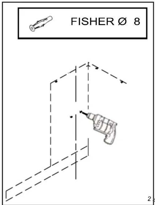
2a Using an 8 mm bit, drill in the centres marked according to the instructions in points 1c and 1d (the holes must be at least 60 mm in depth)

STEP 3
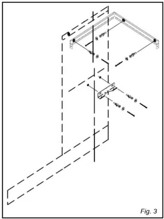
3a Insert 5 (five) FISCHER plugs into the holes made as described in point 2a.
3b Fix the lower bracket in place with the screws, not forgetting to insert the washers.
3c Fix the upper bracket in place with the screws.
ATTENTION!
Use a level to make sure that the brackets have been correctly positioned.
STEP 4
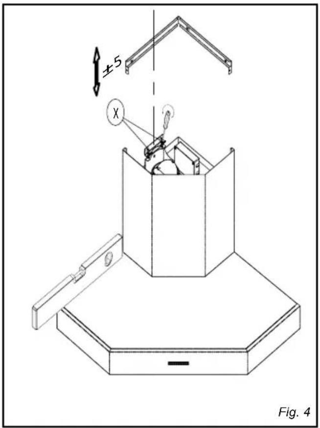
4a Hang up the extractor hood by inserting the two screws X into the slots in the lower bracket.
4b Using a screwdriver with a cross-headed tip, adjust the two screws so that the extractor hood is perfectly level
ATTENTION!
Place the level on top part of the extractor hood. Make sure that the extractor hood is positioned on a level with the mark made on the wall as described in point 1a. If necessary, regulate the position with the screws described in point 4b.
STEP 5
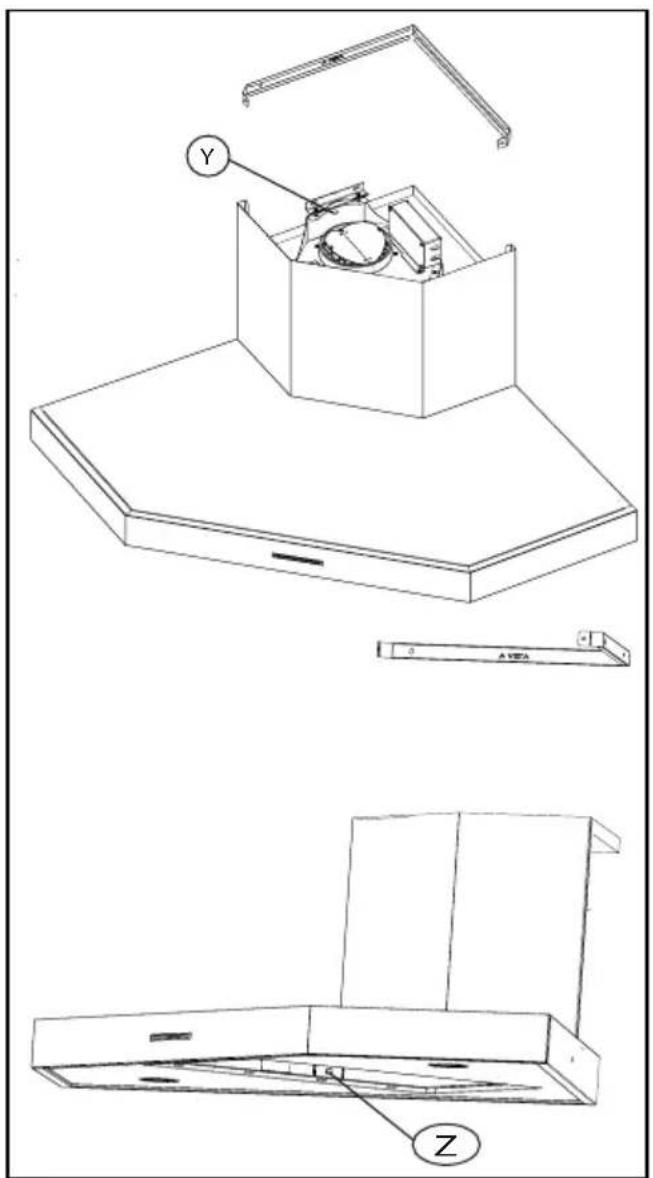
5a Mark the centre of hole Y (inside the upper part) and holes Z (inside the lower part) on the wall.
ATTENTION!
To access the interior part of the hood, remove-de the alluminium filter.
5b Remove the hood from the wall.
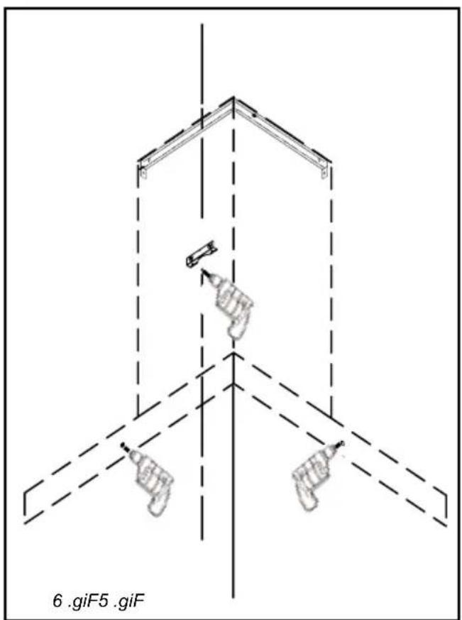
STEP 6
6a Using an 8 mm bit, drill in the centres formed with the operations described in point 5a (the holes must be at least 60 mm in depth)
STEP 7
7a Insert 3 (three) FISCHER plugs into the holes made as described in point 6a.
7b Hang up the extractor hood as described in point 4a.
ATTENTION!
Check the position of the extractor hood again with a level.
Regulate any misalignment with the screw as described in point 4a.
7c Fix the extractor hood in place with the screws and washers.
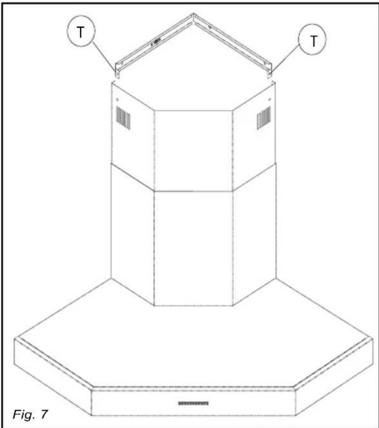
7d Allow the tube to slight within the stack towards the upper bracket and lock it in place with the two screws T inserted inside the bracket (use a flat-tipped screw driver)
ATTENTION!
Prior to operation 7d:
- Connect the exhauster with a 120 mm int. exhaust pipe.
Use the supplied 150 to 120 mm plastic reduction.)
- Connect the power flex to the electricity main.
natural_image
Isometric line drawing of a 3D geometric structure with labeled 'T' components, no text or symbols present.ELECTRICAL CONNECTIONS:
before carrying out any electrical connection, make sure that the voltage corresponds to the one mentioned on the label located on the inside of the appliance. It is advisable to entrust the installation of the electrical connection to a qualified technician.
Appliance provided without plug: please connect a plug or an omni-polar switch in compliance to the existing local regulations, and with an opening connection distance not inferior to 3 mm, The earth wire must not be interrupted by the switch.
Foster decline any responsibility for any inconveniences deriving from the non-observance of the aforesaid instructions of the use of materials which are not in compliance with the existing regulations.
CONTROL PANEL:
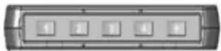
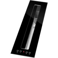
The control panel is electronic and is positioned in the lower-end part of the hood.
FUNCTION OF BUTTONS:
1) TURN-ON 1 ^st SPEED AND MOTOR TURN-OFF
2) TURN-ON 2 ^nd SPEED AND MOTOR TURN-OFF
3) TURN-ON 3 ^rd SPEED AND MOTOR TURN-OFF
4) TURN-ON 4 ^th SPEED AND MOTOR TURN-OFF
5) Light ON/OFF button
REMARKS:
- After 40 hours use of the hood, at motor and light switched off, indicator of key 5 flash to signal the need to clean st. steel filters.
ATTENTION!
Press for long time key n° 5, at motor and light switched off: the alarm is reset.
- After 120 hours use of the hood, at motor and light switched off, indicator of key 5 and 1 flash to signal the need to clean carbon filters.
Press for long time key n° 5, at motor and light switched off: the alarm is reset. - It is possible to automatically delay the stalling of the engine by pressing for long one of the speed keys.
The engine will run for 15 minutes.
P1P2P3P4P5
MAINTENANCE:
Please switch-off the electrical power, or disconnect the appliance before carrying out any maintenance operation.
1) Cleaning of the stainless steel parts: in order to avoid scratches in the steel surfaces, please don't use abrasive powders or brushes. Use liquid detergents specifically made for stainless steel items.
2) Filter Cleaning: Remove the filter from the container and wash it in the dishwasher or with soapy water, without rubbing it with a cloth or a sponge.
Before replacing the filter, carefully dry it without deforming it.
3) Led replacement: switch-off the electrical power, or disconnect the appliance, and by means of a screwdriver, raise the ring which sustains the glass, taking care not to damage it. Remove the glass and replace the light bulb with a similar one (halogen lamp 12V–20 W). Re-assembly the safety glass and the sustaining ring (refer to the sketch:
ATTENTION:
- The expelled air must not be convoyed in ducts which are shared by other appliances powered with energy different from the electrical one.
- Should the use of the hood be contemporaneous to other appliances powered by energy different from the electrical one, an adequate ventilation on the room is to be foreseen.
- The use of an open flame under the hood or the preparation of food with an open flame is to be excluded, as this could cause a fire. Check that the oil doesn't overheat during the frying process in order to prevent it from catching fire.
- The non-compliance to filter cleaning recommendations, causes a risk of fire. It is of course recommended to follow the said instructions
IMPORTANT:
The use of the hood in presence of other non-electrical appliances (such as, but not limited to, wood-burning stoves, gas stoves, non-electrical water-heaters) requires the presence of an external exhaust which ensures a good ventilation of the room.
Verify the conditions of the exhaust chimney in case the hood is not used for a long period of time.
Please also pay the maximum attention to the local standard regulations concerning exhaust scavenging.
All recommendations on the subject should be scrupulously observed in order to avoid unpleasant inconveniences.
THE MANUFACTURER DECLINES ANY RESPONSIBILITY CAUSED BY NON-COMPLIANCE TO THE HERE ABOVE MENTIONED RECOMMENDATIONS.
TECHNICAL FEATURES
| Type | PITAGORA CORNER HOOD |
| Code | 2439.001 |
| Dimensions | 898X898X90 mm |
| Capacity | 850 |
| Cooking surface lighting | halogen led n. 2x20 W |
| Anti-grease !Iters | 2 |
| Working speed | 4 |
| Operation | Suction type |
| Finishing | Foster brushed !nish |
| Air outlet diameter | Ø 120-150 mm |
| Voltage | 220 – 240 V |
| Frequency | 50 Hz |
| Max absorbed Power | 290 W |


- OPERAZIONE N° 3
- OPERAZIONE N° 7
- MANUTENZIONE:
- INSTRUCTIONS FOR INSTALLATION, MAINTENANCE AND USE OF THE PITAGORA CORNER HOOD
- GENERAL INFORMATION:
- USE:
- HOW TO INSTALL PITAGORA CORNER HOOD
- STEP 1
- ATTENTION:
- STEP 2
- STEP 3
- ATTENTION!
- STEP 4
- STEP 5
- STEP 6
- STEP 7
- Prior to operation 7d:
- ELECTRICAL CONNECTIONS:
- CONTROL PANEL:
- FUNCTION OF BUTTONS:
- REMARKS:
- MAINTENANCE:
- IMPORTANT:
Brand : Foster
Model : Pitagora
Category : Range hood