
TVVR60020 - Voice recorder ABUS - Free user manual and instructions
Find the device manual for free TVVR60020 ABUS in PDF.


| Product Type | Digital Voice Recorder |
| Brand | ABUS |
| Model | TVVR60020 |
| Dimensions (W x D x H) | 100 x 30 x 15 mm |
| Weight | 50 g |
| Power Supply | Rechargeable lithium-ion battery, 500 mAh |
| Internal Storage | 16 GB (expandable via microSD card up to 128 GB) |
| Recording Format | MP3, WAV |
| Battery Life | Up to 20 hours of continuous recording |
| Connectivity | USB 2.0, 3.5 mm headphone jack |
| Main Features | Voice recording, playback, voice activation, noise reduction, stealth mode |
| Care and Cleaning | Clean with a soft, dry cloth. Avoid moisture and shocks. |
| Security | Password lock to protect files |
| Spare Parts and Repairability | Battery and memory card replaceable. Spare parts available on request. |
| General Information | Indoor use, operating temperature 0°C to 40°C |
Frequently Asked Questions - TVVR60020 ABUS
User questions about TVVR60020 ABUS
0 question about this device. Answer the ones you know or ask your own.
Ask a new question about this device
Download the instructions for your Voice recorder in PDF format for free! Find your manual TVVR60020 - ABUS and take your electronic device back in hand. On this page are published all the documents necessary for the use of your device. TVVR60020 by ABUS.
USER MANUAL TVVR60020 ABUS
ABUS Digitalrekorder TVVR50011 / TVVR50021 TVVR60010 / TVVR60020

natural_image
Exterior view of a black and silver electronic device with circular buttons and a digital display (no visible text or symbols)These user manual contains important information for installation and operation.
This should be also noted when this product is passed on to a third party.
Therefore look after these operating instructions for future reference!
A list of contents with the corresponding page number can be found in the index.
Français

natural_image
Exterior view of a modern office building with the logo ABUS on the facade, surrounded by greenery and trees (no visible text or symbols on the building itself)natural_image
Exterior view of a modern multi-story building with glass facade and surrounding greenery (no visible text or signage),Network Time Protokoll'
,Universal Serial Bus'
TVVR50011 / TVVR50021
TVVR60010 / TVVR60020
Hersteller
86444 Affing (Germany)
ABUS Digital Recorder TVVR50011 / TVVR50021 TVVR60010 / TVVR60020

natural_image
Exterior view of a black and silver ABBIS audio workstation (no visible text or symbols on main body)User manual
Version 1.4
CE
English
These user manual contains important information for installation and operation. This should be also noted when this product is passed on to a third party. Therefore look after these operating instructions for future reference! A list of contents with the corresponding page number can be found in the index.
i
Pay attention to the information in the separate quick guide, plus the notes on the CD and in the accompanying documentation on “Web server control” and “Clients Software”. These can be found on the Internet under www.abus-sc.com.
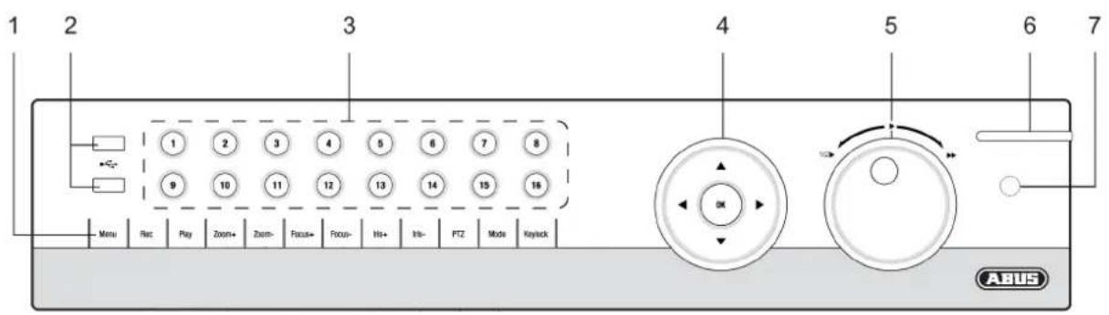
Device overview

See System operation on page 13.
Front
Rear


The diagram shows the TVVR50021 version with 16 channels.
The models TVVR50011, TVVR60010 and TVVR60020 are similar.
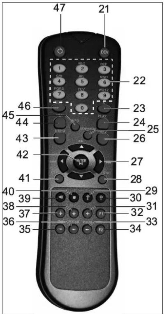
Remote control (TVAC40930 optional available)
Device overview ....3
Quick guide....8
Before you start....8
Installing the HDD 8
Establishing the connections 8
Configuring the device ....8
Important safety information....9
Explanation of symbols....9
Proper use 9
General information 9
Power supply 9
Overloading / overvoltage 10
Cables....10
Installation location / operating environment ....10
Remote control....10
Care and maintenance....11
Accessories....11
Putting into operation....11
Children and the device ....11
Introduction 12
General information 12
Unpacking the device....12
Scope of delivery 12
System operation....13
General information ....13
Operating elements on the device....13
Connections on the rear of the device 14
Operating elements on the remote control 14
Mouse operation ....15
On-screen keyboard 16
Starting the device ....16
Switching off, locking and rebooting the device....16
Status displays....17
General information ....17
DVR status LED....17
Camera selection keys – status LED....17
Voice output....17
Displays on the monitor ....17
Setup wizard....18
Setting up the system ....18
Setting up the administrator....18
General Settings ....18
HDD Management ....19
Record Settings ....19
Network Settings....19
Camera Management ....20
Live view 21
Overview 21
Status symbols ......21
Pop-up menu for mouse operation ....21
Contents
Digital Zoom....22
Secondary monitor....22
System Settings 23
Setting the camera output....23
Record Settings 24
Set-up....24
General settings....24
Advanced settings ....24
Schedule 25
Manual Record....25
Playback....26
General information 26
Playback screen ....26
Using the control panel....26
Playback through video search....26
Playback: Advanced video search....27
Playback from the live view screen....27
PTZ control....28
General information 28
Using the PTZ control panel 28
Pop-up menu for mouse operation....28
PTZ Settings 29
Preset Settings....29
Tour Settings....30
Call a tour set in the PTZ-Camera....30
Pattern Settings ....31
Device menu 32
Menu overview....32
Menu description ....32
Manual Record....33
Video Search ....33
Parameters for Video Search ....33
Results 34
Video Export ....35
Manual Alarm....36
HDDs....36
Installing the HDD....36
Initialising the HDD 37
HDD Management parameters....37
Setting the HDD....37
Adding a network HDD 38
Checking the HDD status ....38
Setting up the HDD alarm....38
System Settings 39
Overview 39
General Settings....39
System Settings: Camera....40
Setting up of zones....41
Zones: Schedule and notification ....42
Adding a network camera....42
System Settings: Record 43
System Settings: Network....43
System Settings: Alarm 43
System Settings: PTZ 43
System Settings: RS232....43
System Settings: Display 43
System Settings: Exception....44
System Settings: User 44
System Settings: UVV 45
Maintenance 46
Upgrading the device....46
Log Search 47
Default Settings 48
Import / Export Configuration....48
Information 48
Shutdown 48
Network 49
General information 49
Terms and definitions ......49
Network layout....50
Network configuration....50
Alarm....54
Alarm overview ....54
Alarm Input ....54
Alarm Output....56
IP alarm module....56
Troubleshooting....57
Device cleaning and care....57
Note....57
Index....58
Technical data ....59
HDD storage capacity....61
Disposal 62
Information on the EU directive on waste electrical and electronic equipment 62
Information on handling batteries 62
Important information on disposing of batteries....62
Information on the European RoHS directive 62
Glossary....63
Overview of specialist terms....63
Internal HDD 65
Quick guide
Before you start
The following preparatory steps must be made:
- Pay attention to the general information, safety information and notes on setting up and connecting the device (see page 9).
- Check the contents of the package for completeness and damages.
- Insert the batteries into the remote control.

Note
Pay attention to the information in the separate quick guide.
Installing the HDD

Warning
Switch off the device and disconnect it from the mains power supply. Pay attention to the required earthing of the device to avoid static discharge.
- Install one or more HDDs (see the separate quick guide).
- E establish the connection to the motherboard using the red data cable (small connector).
- Connect the power supply cable (large 5-pin connector).
- Check that the connections are secure.
- Close the housing.

Note
Only use HDD's that are approved for video recording and 24/7 usage.
Establishing the connections

Note
Pay attention to the minimum radius when laying cables. Do not kink the cable.
- Connect the analogue cameras with BNC connections 1 to 8/16.
- Connect the audio connections.
- Connect the network cameras and LAN connection on the device to the network.
- Connect the sensors to the alarm inputs.
-
Connect the monitor to the HDMI, VGA or BNC connection.
-
Connect the mouse to the USB port.
- Establish a connection to the mains power supply.
- Switch on the device using the POWER switch on the rear. The DVR status display on the front of the device lights up.
Configuring the device

Note
Pay attention to the information in the separate quick guide.
- Proceed through the individual steps in the setup wizard (see page 18).
• The following settings are configured in sequence:
• Language selection for the user interface - Administrator setup
• General settings (date, time etc.)
• HDD manag ement (initialisation etc.) - Recording settings
- Network settings
- Camera management

Note
Subsequent changes to the date and time can lead to the loss of data!

Note
Check the ABUS homepage (www.abus-sc.com) if for this device any firmware updates are available and install these

Note
Make sure to frequently monitor the recorder status after the installation. HDD status and recording settings should be checked in order to insure recording.
- Pay attention to the menu overview on page 32, plus the notes and explanations on basic system operation on page 13.
Pay attention to the notes on the following:
| Live view | Page 21 |
| Playback | Page 26 |
| PTZ | Page 28 |
| Data backup | Page 35 |
| Troubleshooting | Page 57 |
Important safety information
Explanation of symbols
The following symbols are used in this manual and on the device:
Symbol Signal word Meaning
 | Warning | Indicates a risk of injury or health hazards. |
 | Warning | Indicates a risk of injury or health hazards caused by electrical voltage. |
 | Important | Indicates possible damage to the device/accessories. |
| (P44) | Note | Indicates important information. |
The following labels are used in the text:
Meaning
| 1. ... | Set of tasks or instructions with a defined sequence in the text |
| 2. ... | |
| ... | Set of points or warnings without a defined sequence in the text |
| ... |
Proper use
Only use the device for the purpose which it was designed and built for. Any other use is considered inappropriate.
This device may only be used for the following purpose(s):
- This hybrid digital r ecorder is used in combination with connected video signal sources (B/W and colour cameras, IP cameras) and video output devices (CRT or TFT monitors) for object surveillance.

Note
Data storage is subject to national data-protection guidelines.
During installation, inform your customers regarding the existence of these guidelines.
General information
Before using the device for the first time, read the following instructions carefully and pay attention to all warnings, even if you are already familiar with electronic devices.

Warning
All guarantee claims become invalid for damages caused by non-compliance with these operating instructions.
We cannot be held liable for resulting damages.

Warning
We cannot be held liable in the event of material or personal damage caused by improper operation or non-compliance with the safety information.
All guarantee claims are invalid in such cases.
Keep this manual in a safe place for future reference.
If you pass on or sell the device, you must also include this user manual.
This device has been manufactured in accordance with international safety standards.
Power supply
- Only operate this device through a power source which supplies the mains power specified on the type plate.
- If you are unsure of the power supply at the installation location, contact your power supply company.

Warning
Avoid data loss!
Always use an uninterruptible power supply (UPS) with overvoltage protection.
- Disconnect the device from the mains power supply before carrying out maintenance or installation work.
- The on/off switch does not completely disconnect the device from the mains power supply.
- To disconnect the device completely from the mains power supply, the plug must be disconnected from the mains socket. Therefore, the device should be positioned so that direct and unobstructed access to the mains socket is guaranteed at all times and the plug can be disconnected immediately in an emergency.
- To avoid the possibility of fires, the plug should always be disconnected from the network socket if the device is not used for long periods. Disconnect the device from the mains power supply before impending electrical storms, or use an uninterruptible power supply.

Warning
Never open the device on your own! There is a risk of electric shocks! If it is necessary to open the device, consult trained personnel or your local maintenance specialist.
- The installation or modification of a HDD should only be made by trained personnel or your local maintenance specialist.

Warning
The installation of additional equipment or modification of the device invalidates your guarantee if not carried out by trained personnel. We recommend having the HDD installed by a maintenance specialist. Your guarantee is invalidated in the event of improper installation of the HDD.
Overloading / overvoltage
- Avoid overloading of mains sockets, extension cables and adapters as this can result in fires or electric shocks.
- Use overvoltage protection to prevent damages caused by overvoltage (e.g. electrical storms).
Cables
- Always hold cables by the connector, and do not pull the cable itself.
- Never touch the mains cable with wet hands, as this can lead to a short circuit or electric shock.
- Never position the device, furniture or other heavy items on the cable. Ensure that the cable does not become kinked, especially on the connector and sockets.
- Never knot the cable, and do not tie it to other cables.
- All cables should be laid so that they cannot be stepped on or cause an obstruction.
- A damaged mains cable can cause a fire or electric shock. Check the mains cable from time to time.
- Never modify or manipulate the mains cable or plug.
- Do not use plug adapters or extension cables that do not conform to the applicable safety standards, and do not make alterations to power supply cables or mains cables.
Installation location / operating environment
- Position the device on a firm, level surface and do not place any heavy objects on the device.
- The device is not designed for operation in rooms subject to high temperatures or moisture (e.g. bathrooms), or in excessively dusty rooms.
- Operating temperature and ambient humidity: -10 °C to 55 °C, maximum 85% relative humidity. The device may only be operated in moderate climate conditions.
Ensure the following:
- Sufficient ventilation must be present at all times (do not place the device in a storage rack, on thick carpets, on a bed or anywhere where the ventilation slots are covered. Make sure that a gap of at least 10 cm is present on all sides).
- The device must not be exposed to direct heat sources (e.g. heaters).
- The device must not be exposed to direct sunlight or strong artificial light.
- The device must not be placed in close proximity to magnetic fields (e.g. loudspeakers).
- Na- ked flames (e.g. candles) must not be placed on or near the device.
- Contact with spraying or dripping water and aggressive liquids must be avoided.
- The device must not be operated in close proximity to water, and must not be submerged under any circumstances (do not place objects containing water on or near the device, such as vases or drinks).
• Foreign objects must not penetrate the device.
- The device must not be exposed to strong variations in temperature, as this can lead to condensation and electrical short circuits.
- The device must not be exposed to excessive jolts or vibrations.
Remote control
- Remove all batteries if the device will not be used for a sustained period, as these can leak and damage the device.
Care and maintenance
Maintenance is necessary if the device has been damaged. This includes damage to the plug, mains cable and housing, penetration of the interior by liquids or foreign objects, exposure to rain or moisture or when the device does not work properly or has fallen.
- Disconnect the device from the mains power supply before maintenance (e.g. cleaning).
- If smoke develops or unusual noises or odours are detected, then switch off the device immediately and pull the mains plug from the socket. In such cases, the device should not be used until it has been inspected by a qualified technician.
- Maintenance work should only be carried out by qualified specialists.
- Never open the housing on the device or accessories. There is a risk of fatal injury due to an electric shock when the housing is opened.
- Clean the device housing and remote control with a damp cloth.
- Do not use solvents, white spirit or thinners as these can damage the surface of the device.
- Do not use any of the following substances:
- Salt water, insecticides, solvents containing chlorine or acids (ammonium chloride) or scouring powder.
- Gently rub the surface with a cotton cloth until it is completely dry.

Warning
The device works under dangerous voltages. The device must only be opened by authorised specialists. All maintenance and service work must be carried out by authorised firms. Improper repairs can expose device users to the risk of fatal injury.
Accessories
- Only connect devices that are suitable for the intended purpose. Otherwise, hazardous situations or damage to the device can occur.
Putting into operation
- Observe all safety and operating instructions before putting the device into operation for the first time.
- Only open the housing to install the HDD.

Warning
When installing the device in an existing video surveillance system, ensure that all devices are disconnected from the mains power supply and low-voltage circuit.

Warning
If in doubt, have a specialist technician carry out assembly, installation and connection of the device.
Improper or unprofessional work on the mains power supply or domestic installation puts both you and other persons at risk.
Connect the installations so that the mains power circuit and low-voltage circuit always run separately from each other. They should not be connected at any point or become connected as a result of a malfunction.
Children and the device
- Do not allow children access to electrical devices. Never allow children to use electrical devices without supervision. Children may not be able to accurately detect possible risks. Small parts can be life-threatening if swallowed.
- Keep batteries away from small children. Call for medical assistance immediately if a battery is swallowed.
- Keep packaging materials away from children (danger of suffocation).
- This device should not be used by children. If used improperly, spring-loaded parts can be ejected and cause injuries to children (e.g. eye injuries).
Introduction
Dear customers,
Thank you for purchasing this product.
This product complies with current domestic and European regulations. Conformity has been proven, and all related certifications are available from the manufacturer on request (www.abus-sc.com).
To maintain this status and to guarantee safe operation, it is your obligation to observe these operating instructions!
Read the entire operating manual carefully before putting the product into operation and pay attention to all operating and safety information!
All company names and product descriptions are trademarks of the corresponding owner. All rights reserved.
In the event of questions, please contact your local maintenance specialist or dealer.

Disclaimer
These operating instructions have been produced with the greatest care. Should you discover any missing information or inaccuracies, please contact us under the address shown on the back of the manual. ABUS Security-Center GmbH does not accept any liability for technical and typographical errors, and reserves the right to make changes to the product and operating instructions at any time and without prior warning. ABUS Security-Center GmbH is not liable or responsible for direct or indirect damages resulting from the equipment, performance and use of this product. No forms of guarantee are accepted for the contents of this document.
General information
In order to use the device correctly, read this user manual carefully and keep it in a safe place for later use.
This manual contains instructions on recorder operation and maintenance. Consult an authorised specialist if the device needs to be repaired.
Unpacking the device
Handle the device with extreme care when unpacking it.
The packaging is made of reusable materials, and should always be passed on for recycling.
We recommend the following:
Paper, plastic packaging, cardboard and corrugated cardboard should be disposed of in the appropriate recycling containers.
If recycling containers are not available in your local area, then you can dispose of these materials as domestic waste.
If the original packaging has been damaged, inspect the device. If the device shows signs of damage, then return it in the original packaging and contact the manufacturer.
Scope of delivery
- ABUS digital recorder
- Mains cable
- SATA cable and screws for HDD
- Bracket and screws for server racks
- Software CD
- User manual
- Quick guide
System operation
General information
The device can be controlled as follows:
- Using the operating elements on the front of the device
• Using the remote control
• Using the USB mouse
Operating elements on the device
i
Note
Pay attention to the overview on page 3.
| No. | NameFunction |
| 1 | Recorder operating keys:MENU:Calls up the main menuSwitches the key tones on and off (press and hold down for 5 seconds)REC:Calls up the menu for manual recordingPLAY:Opens the playback menuZOOM+:Zooms in on the image section in PTZ modeZOOM:-Zooms out of the image section in PTZ modeSwitches the video output in live mode: Monitor – Spot Monitor or Video Out – Video Spot OutFOCUS+:Sets the focus in PTZ modeFOCUS- Sets the focus in PTZ modeIRIS+:Opens the irisIRIS-:Closes the iris in PTZ modePTZActivates the PTZ controlMODE:Switches the screen viewKEYLOCK:Locks the control keys |
| 2 | USB ports:For external USB 2.0 devices (e.g. mouse, external disk drive or DVR writer) |
| No. | NameFunction |
| 3 | Camera selection keys (1, 2, 3...):Displays the camera status:White: Camera is connectedBlue: Connected camera is recordingNot lit: No camera connectedIn the live view:Selects the camera and displays the full-screen view |
| 4 | Directional keypad:During playback:▲,▼ Sets the speed◀,▶ Previous / next dayIn the live view:Selects the channelIn menus:NavigationOK key:Press and hold for 5 seconds to switch the device on and offConfirms the selectionChecks / unchecks the boxesDuring playback:PLAY/PAUSEIncreased/ decreased playback speed:Normal playback speed |
| 5 | Jog Shuttle:During playback:Outer ring (shuttle ring) change playback speedInner ring to play single frames in single mode In menus:Inner ring moves the cursor upwards / downwardsOuter ring moves the cursor left / rightIn the live view:Selects the channel |
| 6 | DVR status LED:Displays the device status:White (constantly lit): System status is OKWhite (flashing): System status is OK, recording settings are stored, surveillance mode is activeBlue (constantly lit): At least one camera is currently recordingRed (constantly lit): System maintenance required |
| 7 | IR receiver:For the remote control |
Connections on the rear of the device
i
Note
Pay attention to the overview on page 3.
| No. | NameFunction |
| 8 | VIDEO SPOT OUT: BNC video outputWhen using a HDMI/VGA monitor:No video signal is displayed.When using no HDMI/VGA monitor:The video spot signal is displayed..AUDIO SPOT OUT: Cinch audio output |
| 9 | MAIN: BNC video outputWhen using a HDMI/VGA monitor:Video spot signal is displayed.When using no VGA monitor:The main video signal is displayed.AUDIO OUT: Cinch audio output (synchronised with video output) |
| 10 | LINE IN 1, 2: Cinch audio input |
| 11 | VGA:VGA monitor connection (9-pin), video output signal |
| 12 | RS-232:Serial port – no functionality |
| 13 | HDMIHDMI monitor connection |
| 14 | LAN:Ethernet LAN connection |
| 15 | USB port |
| 16 | ALARM IN:RS-485 connection for PTZ camerasMax. 16 alarm inputsALARM OUT:Max. 4 relay outputs |
| 17 | Connection for earthing line |
| 18 | Power switch and mains power connection:100–240 V AC, 50–60 Hz |
| 19 | LOOP OUT: Connection for looped video signals (cable available separately) |
| 20 | VIDEO IN: BNC inputsAUDIO IN: Cinch inputs |
i
Note
All audio inputs have no audio amplifier -> the audio signal has to be amplified before connected. Therefore you can use a microphone amplifier.
Operating elements on the remote control
i
Note
Pay attention to the remote control diagram on page 4.
| No. | NameFunction |
| 21 | DEV:Assigns the remote control with the device ID |
| 22 | Alphanumeric keys:Selects the camera (channel) in the live viewEntry of letters and digits in system fields |
| 23 | A:Changes the entry format (upper / lower case, symbols, digits) |
| 24 | PLAY:Starts playback |
| 25 | VOIPNot used |
| 26 | PREV:Changes the screen display in the live view |
| 27 | Navigation keys:During playback:▲,▼ Sets the speed◀,▶ Previous / next dayIn the live view:Selects the camera (channel selection)In menus:Navigation |
| 28 | ESC:Not used |
| 29 | Not used |
| 30 | Not used |
| 31 | Zoom +:Zooms in on the image section in PTZ mode |
| 32 | F1:In lists:• Selects all available options |
| 33 | Zoom -:Zooms out of the image section in PTZ mode |
| 34 | F2:Switches between tabs |
| 35 | IRIS-: In PTZ mode:• Closes the iris |
| 36 | Focus-: In PTZ mode:• Brings the image section into focus |
| 37 | IRIS+: In PTZ mode:• Opens the iris |
| 38 | Focus+: In PTZ mode:• Brings the image section into focus |
| 39 | ◀II: Pause / reverse playback |
| 40 | ■: Stops playback |
| 41 | PTZ:Switches on PTZ control |
| 42 | Enter ▶II:• Confirms the selection• Checks / unchecks the boxesDuring playback:• PLAY/PAUSESingle play mode:• Advances by a single frame |
| 43 | MENU:• Calls up the main menu• Switches the key tones on and off (press and hold down for 5 seconds) |
| 44 | REC:Opens / starts manual recording |
| 45 | INFO:• Switches to another monitor in the live view |
| 46 | EDIT:General use:• Activates the text entry; backspace in text fields |
| 47 | ◎ POWER:Switches on/off (hold down for 5 seconds) |
Mouse operation

Note
Further descriptions in these operating instructions are made with the mouse.
The device is suitable for use with a USB mouse.
Connect the mouse to the USB port.
| Button | Function |
| Left Single-click:Selection in menu, activation of an entry field or tabDouble-click:Switches between the screen display of single and multiple images in the live view and during playbackClick and drag:In PTZ mode: Camera controlSet-up of alarm areas or zones | |
| Right $single-click:Calls up the pop-up menu | |
| Scroll wheel | In the live view:Shows previous / next cameraIn menus:Scrolls through the menus |
On-screen keyboard
The on-screen keyboard appears after clicking on a text entry field with the mouse:

The keys have the same function as on a computer keyboard.
• To enter the character, left- click the mouse.
• To finish data entry, press Enter.
- To delete the character in front of the cursor, click on ←.
- To switch between upper and lower case, click on the framed a symbol. The current setting is displayed above the keyboard.
• To cancel the entry or exit the field, press ESC.
Starting the device

Important
The device must only be operated with the mains power specified on the type plate.
For safety reasons, use an uninterruptible power supply (UPS).
After the device has been connected to the power supply and the main switch on the rear of the device is switched on, the DVR status LED lights up.
- The device carries out a self- test during the start-up procedure. The status of the DSP processors and the HDD appears. If an "X" is displayed, then this indicates that the initialisation has failed or the HDD is not installed.
- The setup wizard appears. Exit the wizard to access the live view.
Switching off, locking and rebooting the device
Click on "Shutdown" in the main menu. The overview appears.
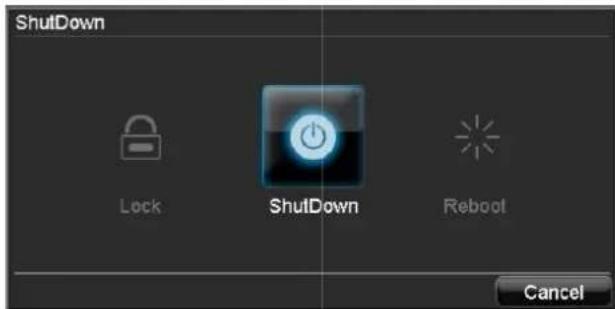
- To switch off the device, select ShutDown and confirm by pressing Yes. The device is then switched off.
- Do not press any keys during the shutdown procedure.
- To lock the system, select the corresponding Lock symbol on the left. The user interface is now locked and a password must be entered to access the menu.
- To reboot the device, select the corresponding Re-boot symbol on the right. The device is then re-booted.
Switching on the device
- Press and hold the OK key for 5 seconds to switch the device back on.
Status displays
General information
The following status displays indicate the current operating state:
• LEDs on the front of the device
• Acoustic signal tones
- Icons (display elements) on the monitor

Note
Pay attention to the information in the separate quick guide.
DVR status LED
| State | Function |
| White (constantly lit): System status is OK | |
| White (flashing): System status is OK, recording settings are stored, surveillance mode is active | |
| Blue (constantly lit): At least one camera is currently recording | |
| Red (constantly lit): System maintenance required | |
Camera selection keys – status LED
| State | Function |
| Off: No camera connected | |
| White (constantly lit): | Camera is connected |
| Blue (constantly lit): | Camera is currently recording |
Voice output
The device gives information regarding the most important functions or operating states via voice output, for example:
- "Motion detected"
- "Playback started"
- "Main menu opened"

Note
Connect the external loudspeakers to the AUDIO OUT connection.
Displays on the monitor
The device shows the date and time, camera name and whether a recording is in progress.
• Continuous recording: Blue "R"
• Event recording: Red "R"
Setup wizard
Setting up the system
The setup wizard guides you through the necessary basic system settings. The DVR is then set up for recording and surveillance.

Note
All detailed settings can be found in the device menu (see overview on page 32).
The language selection appears after switching on for the first time:

- Click the entry field and select the desired language from the list. Click on Next to continue. The following query appears:

- Click on "Next" to start the wizard.

Note
After the system is set up, you can uncheck the box. The setup wizard is then no longer started automatically.
Setting up the administrator

Warning
Note down the admin password. The following password is preset
"1 2 3 4 5"

- Click the entry field and enter your admin password.
- To assign a new password, check the box next to New Admin Password.
- Enter the new password and confirm in the field below.
- Click on Next.
General Settings
- Click on "Enter" in the next window.
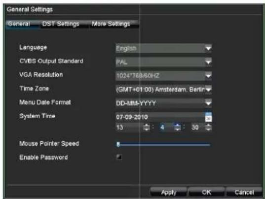
- Enter the system time (date and time). Click on Apply to accept the data. Exit the setting by pressing OK, then click on Next.
HDD Management
- Click on "Enter".

- To set up a new HDD, check the box and then click on Init.

Warning
All data on the drive is deleted!
- Confirm the prompt by pressing OK. The HDD is then set up for operation. The progress is displayed on the status bar.
- Exit the setting by pressing OK, then click on Next.
Record Settings
- Click on "Enter".
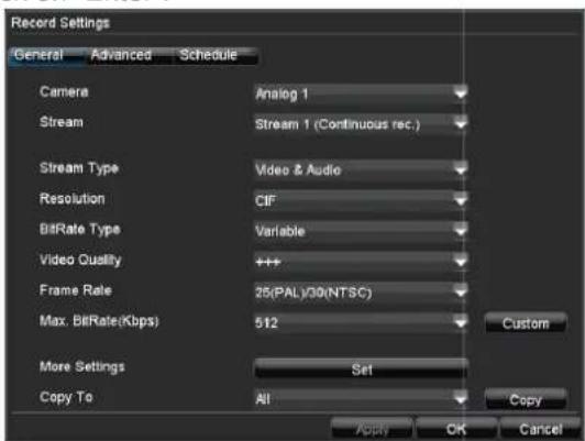
- Select the camera in the "General" tab and specify the settings.
- Click on the "Schedule" tab and then on Edit.

- Check the "Enable Schedule" box and All Day. Recording is then switched on for the entire day.
-
Exit the setting by pressing OK. The settings are displayed in colour in the schedule overview.
-
To transfer this schedule to other cameras, first select the camera (or "All" if all cameras should have the same settings) and confirm by pressing Copy.
- Exit the setting by pressing OK, then click on Next.
Network Settings
- Click on "Enter".
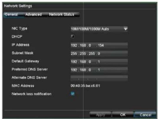
i
Note
To check whether DHCP can be selected (or if you have to set the IP address and other settings manually), consult your network administrator.
- DHCP activated: If DHCP is set up in the network router, then check the DHCP box. All network settings are then made automatically.
- DHCP not activated: Enter the data manually (IP address, subnet mask and default gateway = IP address of the router).
A typical address specification is as follows:
• IP address: 192.168.0.50
- Subnet mask: 255.255.255.0
- Default gateway: 192.168.0.1
• Preferred DNS server: 192.168.0.1
- Exit the setting by pressing OK, then click on Next.
Camera Management
1. Click on Enter.

2. Click on Status. The camera overview opens.
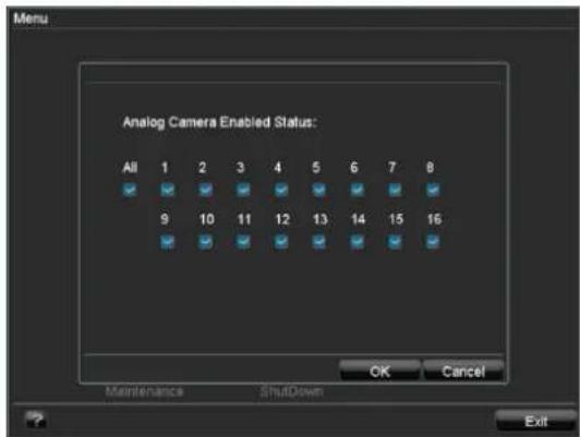
3. Deactivate the analogue camera inputs by unchecking the boxes.
4. Confirm with OK.
i
Note
After making changes, a message appears indicating that the system will be rebooted to activate the settings.
Confirm with Yes.
The reboot process is then made.
5. Open the Camera Management screen. You can add IP cameras by clicking on Add.

6. Exit data entry by pressing OK.
7. Click on Done to exit the wizard.
i
Note
You can edit all of the settings after exiting the wizard.
To do this, open the menu (see page 32).
Live view
Overview
The live view starts automatically after the device is switched on.
You can also go back to the live view by pressing the Menu key repeatedly.

natural_image
Exterior view of a modern white building with a red-and-white roof, featuring the logo and entrance (no visible text beyond signage)The following menus are found in the screen header:
- Menu
- Playback
• PTZ
The view pop-up menu is found on the right. The time and date are displayed on the right.
- To open the view pop-up menu, click on the rectangular symbol at the top-right of the menu bar.
- Click on one of the symbols to switch between the different views.

flowchart
graph TD
    A[" "] --> B[" "]
    B --> C[" "]
    C --> D[" "]
    D --> E[" "]
    E --> F[" "]
    F --> G[" "]
    G --> H[" "]
    H --> I[" "]
    I --> J[" "]
    J --> K[" "]
    K --> L[" "]
    L --> M[" "]
    M --> N[" "]
    N --> O[" "]
    O --> P[" "]
    P --> Q[" "]
    Q --> R[" "]
    R --> S[" "]
    S --> T[" "]
    T --> U[" "]
    U --> V[" "]
    V --> W[" "]
    W --> X[" "]
    X --> Y[" "]
    Y --> Z[" "]
The signals of the connected cameras are displayed on the main screen.
- By double-clicking the left mouse key, you can display the camera image as a full-screen view or switch back to the original view.
Status symbols
- The following symbols are displayed depending on the operating status of the device:
| Symbol | Meaning |
 | Event detectedMotion detection, alarm triggered by sensor, HDD error etc. |
| RR | Red: RecordingEvent recordingBlue: RecordingContinuous recording |
 | Active channel is the main signal |
 | Active channel sent through AUX Out |
 | Active channel sent through Spot Out |
Pop-up menu for mouse operation

Note
Press the right mouse button when the cursor is positioned on a live image.
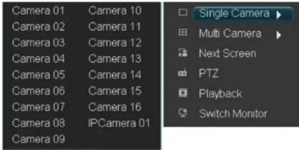
The following settings can be made. The arrow pointing to the right indicates that a sub-menu is opened for selection:
| Single Camera | Kamera 01 |
| Multi Camera | Kamera 02 |
| Next Screen | Kamera 03 |
| Stop Auto-switch | Kamera 04 |
| Digital Zoom | Kamera 05 |
| PTZ | Kamera 06 |
| Playback | Kamera 07 |
| Switch Monitor | Kamera 08 |
| Menu | Kamera 09 |
| Kamera 10 | |
| Kamera 11 | |
| Kamera 12 | |
| Kamera 13 | |
| Kamera 14 | |
| Kamera 15 | |
| Kamera 16 | |
| Single Camera Full-screen view for selected camera | |
| Multi Camera Various camera layouts | |
| Next Screen Displays the next camera(s) | |
| Stop Auto-switch | Starts the camera sequence |
| Digital Zoom Zooms in on the image section | |
| PTZ Activates PTZ mode | |
| Playback Switches to playback mode | |
| Switch Monitor Switches to the next monitor1 | |
| Menu Opens the main menu | |
i
Note
Stop Auto-switch:
Specify the delay in the image sequence in the display settings.
Secondary monitor:
If no secondary monitor is connected, press the ZOOM—key to return to the display.
Digital Zoom
This function opens an image which has been enlarged by four times.

natural_image
Exterior view of a modern building with 'ABUS' signage under a blue sky (no other text or symbols visible)- Left-click the mouse in the small image window and pull a frame around the image section to be zoomed in on whilst holding the button down.
- The selected section is then digitally zoomed.
- To exit the image, first right-click the mouse and then left-click on "Exit".
Secondary monitor
The secondary monitor is used to display a different view to that on the main monitor. The Switch Monitor command is used to switch from the main monitor to the secondary monitor (e.g. to control PTZ cameras or set the view on the secondary monitor).
i
Note
Pay attention to the connections on page 3.
- If the main monitor is connected via VGA, then the secondary monitor can be connected to VIDEO OUT.
- If the main monitor is connected via VIDEO OUT, then SPOT OUT is used for connecting the secondary monitor.
- Click on Switch Monitor to return to the previous screen.
System Settings

Note
The live view can be set as follows.
Open the main menu, then click on "System Settings" and then "Display Settings":

| Video Output HDMI, VGA, MAIN, VGA SPOT OUT Selects the connection where the settings should be changed | |
| Mode Various camera layouts | |
| Dwell Time Switching time between the individual cameras in “Stop Auto-switch” | |
| Camera Order Camera order in the live view | |
| Enable Audio Output | Activates / deactivates audio output on the video output |
| Event Output Port | Used to assign a monitor for event output |
| Event Dwell Time | The period where the event is displayed on the assigned monitor (in seconds) |

Note
HDMI/VGA monitor connected:
An active HDMI/VGA connection is detected automatically ^1 and becomes the main monitor where the audio output is also assigned. The spot signal is assigned to the video output MAIN, where the PTZ mode, playback and live view can be displayed.
If no HDMI/VGA cable is connected during the boot process, the main monitor signal is assigned to the video output MAIN. Connect the HDMI/VGA cable and reboot the device in order to assign the output signal new.
No VGA monitor connected:
The main monitor signal is assigned to the video output MAIN. The spot signal is assigned to VIDEO SPOT OUT.
Setting the camera output
Up to 16 cameras can be set simultaneously in the live view.
- Click on "Set".

- Select the display mode.
- 1×1
- 2×2
- 1 + 5 etc. (the overview changes according to your settings)
- The camera signal is assigned to the corresponding image section using the navigation keys.
- "X" means that this camera is not displayed.
-
Other optional cameras are accessed by pressing ▶.
-
Press ◀ to go back.
-
Click on OK to accept the settings.
Record Settings
Set-up
Open the main menu, then click on "System Settings" and then "Record Settings":

General settings
The following settings can be made in the "General" tab:
| Camera | Camera to be set |
| Stream | Stream 1: Properties for continuous recordingStream 2: Properties for event recordingStream 3: Properties for network transmission |
| Stream Type | VideoVideo & Audio |
| Resolution | 4 CIF2 CIFCIF |
| BitRate Type | In general, the higher the bit rate, the more storage space is required.Variable:Static image – low bit rate; dynamic image – high bit rateConstant:Bit rate remains constant (at maximum bit rate) |
| Video Quality | There are various quality levels:+: Low quality+++++: High quality |
| Frame Rate | Number of images saved per second.The maximum number is dependent on the set resolution. |
| Max. BitRate (Kbps) | Defines the maximum bit rate for the “Constant” bit rate type |
| More Settings | Detailed settings |
| Pre-alarm | Recording period before an alarm (in seconds) |
| Post-alarm | Recording period after an alarm (in seconds) |
| Expiration | Period (in days) after which the recording is deleted automatically at 00:00. The event remains in the log file.0: Recordings are not deleted automatically |
| Redundancy | Redundant recording (yes / no) |
| Copy To | Copies the selected settings to other cameras (all or selected) |
- Select the camera.
-
Select the stream where the specifications should be defined:
-
Stream 1 (Continuous)
- Stream 2 (Event)
-
Stream 3 (Network)
-
Define the recording parameters for the corresponding stream (see table).
- Under "More Settings", select the period for the pre-alarm, post-alarm etc.
- Select the cameras where you wish to copy the settings under "Copy To", then confirm by pressing "Copy".
Advanced settings
In the "Advanced" tab, you can specify whether older recordings are deleted when the HDD memory is full.
Schedule
The schedule is used to specify the recording times and triggers (recording type) for the cameras. Click on the "Schedule" tab:

In the OSD, the hours of the respective days are listed from left to right (the days are listed from top to bottom). A colour key is shown underneath the days (i.e. the recording periods in the schedule are shown in colour according to the trigger (recording types)).
| Colour symbol Key | |
| Blue Normal recording: Period in hours | |
| Green Motion detection | |
| Light blue Motion detection and alarm | |
| Red Alarm | |
| Grey No selection | |
| Green and red Motion or alarm | |
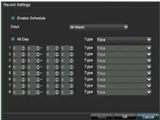
- Select the camera to be set up, then click on "Edit":
-
Check the "Enable Schedule" box.
-
In the drop-down menu next to "Days", either specify the day to be set or select "All Week".
-
Check or uncheck the "All Day" box. When "All Day" is selected, defined times cannot be entered. The setting then applies for the entire day.
-
To make specific time settings, uncheck the "All Day" box.
6.
Specify the recording type in the drop-down menu:
- Normal
- Motion detection
- Alarm
- Motion detection or alarm
-
Motion detection and alarm
-
When making a specific time setting, you can define up to 8 time periods (each from 00:00 to 00:00). The times in the individual periods must not overlap.
i
Note
The "Normal" recording type defines the time window where a recording is made.
The other events (e.g. motion detection and/or alarm) only trigger the recording after the specific event has occurred.
- The camera settings can be copied and applied to all cameras in the "Schedule" tab.
- Select the camera under "Copy" (or select "All"), then confirm by pressing "Copy".
- Exit the settings in the recording screen by pressing OK.
Manual Record
- Press REC to start manual recording:

- Select the camera to start manual recording by clicking the corresponding button.
i
Note
Click "All" to record all connected cameras.
Playback
General information
Playback can be made in three different ways:
• Through the video search in the main menu
- From the live view
• Through the log file in the maintenance menu
Playback screen
Playback is controlled on the control panel:

| No. | Area |
| 1 | Running playback with date and time |
| 2 | Used to select the camera for feedback |
| 3 | Calendar with recording type (see right) |
| 4 | Control panel with time bar |
Using the control panel
The control panel is used for controlling the running play-back. The symbols have the following meaning:

| No. | Meaning / function |
| 1 | Switches audio playback on/off |
| 2 | Defines the start and end point of a video for data backup |
| 3 | Previous recording / day |
| 4 | Goes back 30 seconds |
| 5, 6 | Play or pause for forward / backward playback |
| 7 | Stop |
| 8 | Advances 30 seconds |
| 9 Fast-forward |
| 10 Slow-motion advance |
| 11 Next recording / day |
| 12 Time bar:Click on the time bar with the mouse to continue playback from another pointTo start playback from a specific time, click on the slider and drag it to the required time |
| 13 Recording typeBlue = Continuous recordingRed = Event recording |
| 14 Hides the control panel |
| 15 Exits playback |
i
Note
You can zoom in on the screen image.
• Right-click in the running playback.
- Select "Zoom".
- Zoom mode is now active (see page 22).
Playback through video search
In order to play recorded events, they must first be found. Open the main menu, then click on "Video Search" in the "General" tab:

The following settings are available:
| Camera Camera to be set | |
| Video Type | Schedule, motion detection, alarm or motion detection and/or alarm, manual recording, all |
| File Type Locked, unlocked, all | |
| Start Time End Time | Enter the date and time |
| Details Opens the detailed view.The cameras are listed in sequence. The colour key shows the corresponding recording type. You can then access the recordings by going to the day after or day before. The markings on the time bar can be moved using the mouse to limit the time period for the search. | |
- Click on Search to search for recordings with the corresponding settings. The results are then shown:

- Select the recording by clicking on the line and then on Play.
Playback: Advanced video search
- In the "Video Search" screen, click on the "Event" tab to search for specific recordings which were triggered either by an alarm or motion detection.
- Enter the search criteria (e.g. date, time, alarm inputs, cameras) to carry out the search.
Playback from the live view screen
Click on playback whilst the live view screen is shown:
Playback is controlled on the control panel:

i
Note
Playback starts with the recording of the last five minutes.
The playback screen is divided into four areas:
| No. | Area |
| 1 | Running playback with date and time |
| 2 | Camera menu |
| 3 | Calendar with recording typeBlue = Continuous recordingRed = Event recording |
| 4 | Control panel with time bar |
- Select the camera in the camera menu.
-
Click on the calendar to select a specific recording according to the date and time.
-
Control the playback as follows:
• Using the control panel
- Using the mouse (click on the time bar and drag the slider – use the colour key on page 25 to help with the assignment)
PTZ control
General information
PTZ control is used to access individual PTZ cameras and control them manually.
i
Note
When using ABUS PTZ-Cameras there is the option to configure tours directly in the camera. The advantage is that other control devices, e.g. keyboard, can call the tours as well.
- In order to open the menu of ABUS PTZ-Cameras enter Preset 95. By using the navigation buttons you can move within the menu.
Using the PTZ control panel
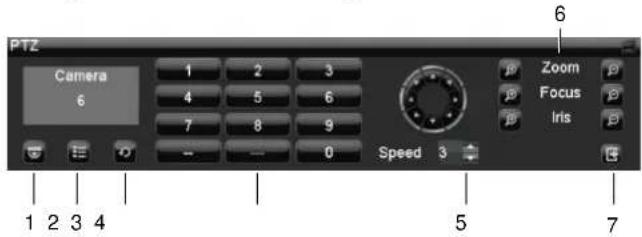
| No. | Meaning / function |
| 1 | Selects and displays the PTZ camera |
| 2 | Call presets |
| 3 | Call tours |
| 4 | Keypad |
| 5 | Speed |
| 6 | Zoom, focus and iris adjustment |
| 7 | Exits the PTZ control |
Pop-up menu for mouse operation
i
Note
Press the right mouse button when the cursor is positioned on a live image.
The following settings can be made. The arrow pointing to the right indicates that a sub-menu is opened for selection:

| Camera PTZ camera selection | |
| Call Preset Selects the set preset | |
| Call Patrol Selects the specific patrol | |
| Call Pattern Selects the defined pattern | |
| Preset Settings | See page 29 |
| Patrol Settings | See page 30 |
| Pattern Settings | See page 30 |
| PTZ Menu Opens the PTZ menu | |
| PTZ Settings | Displays the hardware parameters of the connected camera |
| Exit Exits the PTZ control | |
PTZ Settings
The following settings are necessary on the PTZ camera:

The settings are used for configuring the camera on the corresponding connections.
- Select the installed camera.
- Enter the data of the connected camera.
- The address (ID) is used to clearly identify and control the PTZ camera.
- If several cameras of the same type are connected, then you can copy the settings to the other connections.
- Exit the settings by pressing "Apply" and "OK".
i
Note
Compare the settings with the technical data of the connected camera.
If a connected camera does not work correctly, then check the entered parameters (baud rate, data bit etc.).
Preset Settings
Presets are previously defined locations of a PTZ camera. Various positions can be defined for each PTZ camera. The cameras can then pan and tilt quickly to the corresponding locations.
- Select the camera in the control panel, then click on "Preset Settings" in the pop-up menu:

- Pan, tilt and zoom the camera to the desired position.
- Select "Preset 1" from the list.
- Click on "Set". The position is now set as "Preset 1".
- Repeat steps 1–3 to define further presets.
- Exit the settings by pressing "Apply" and "OK".
i
Note
When using ABUS PTZ-Cameras with the Pelco-D protocol some presets are predefined and cannot be used.
| Preset | Beschreibung |
| 1~64, 100~200 | Call preset 1~64 &, 100~200 |
| 65 Display preset Status | |
| 66 Starts Auto Scan | |
| 67 Auto Flip mode On/Off | |
| 68 Camera reset | |
| 69 Digital Slow Shutter function On/Off | |
| 71~78 Call tour 1~8 | |
| 81~88 Call pattern 1~8 | |
| 91 Calls zero Position | |
| 92 Freezes image | |
| 93 BLC-Function On/Off | |
| 94 Switches between day / night / auto mode | |
| 95 Call OSD menu | |
| 96 Focus adjust | |
| 97 Enable/Disable all alarms | |
Further information can be found in the manual of the PTZ-Camera.
Tour Settings
Patrols are defined tours from position to position that are accessed in sequence on the PTZ camera. The individual positions are presets, which should be set as detailed above. The cameras can then each be moved in sequence to the corresponding positions at a defined speed, where they remain for a set period of time.
Setting a tour within the DVR
Select the camera in the control panel, then click on "Patrol Settings" in the pop-up menu:

- Activate the patrol number.
- Select an active, set preset from the list by checking the box.
- Click on "Set".

- Set the key point number, duration and speed.
• KeyPointNo.: Sequence
- Duration: Time that the PTZ camera waits at a position (in seconds)
• Speed (0–7): Speed of camera movement
5. Accept the settings by pressing "Add".
6. Repeat steps 1–5 to define further patrols.
7. Exit the settings by pressing OK.
i
Note
A patrol consists of at least two preset positions. You can set several patrols for one camera.
The set patrol can be tested as follows: Click on "Start" and monitor the patrol. You can stop the patrol at any time and repeat the patrol settings (e.g. to make corrections).
Call a tour set in the PTZ-Camera
You can also configure tours directly in the camera. The advantage is that other control devices, e.g. keyboard, can call the tours as well. Further information on configuring tours in the PTZ-Camera can be found in the PTZ-Camera manual.
To call the tour you can call a predefined preset or setup a tour in the DVR.
- Activate the patrol number.
- Select a predefined preset:
| Preset | Beschreibung |
| 71 | Starts tour 1 |
| 72 | Starts tour 2 |
| 73 | Starts tour 3 |
| 74 | Starts tour 4 |
| 75 | Starts tour 5 |
| 76 | Starts tour 6 |
| 77 | Starts tour 7 |
| 78 | Starts tour 8 |
- Click on "Set".
- Accept the settings by pressing "Add".
- Exit the settings by pressing OK.
Pattern Settings
Patterns are defined tours from position to position that are accessed in sequence on the PTZ camera. Patterns are recorded live. The system saves the parameters used whilst you move and adjust the cameras in sequence to the corresponding positions at a defined speed.
- Select the camera in the control panel, then click on "Pattern Settings" in the pop-up menu:

- Select the pattern number.
- Click on "Run Record" to start the pattern recording.
- Using the control panel, adjust the camera position and settings that you wish to record as a pattern.
- The recording is made until "Stop Record" is clicked.
i
Note
- Start the recorded pattern by calling up the pop-up menu (right-click in the live view of the PTZ camera).
- Click on "Run Pattern" and click on the desired pattern. The PTZ camera now starts moving to the individual positions. After running through the entire pattern, the process is started again.
Device menu
Menu overview
The following overview shows all menus used to set and control the device.
- When the mouse cursor is pointed at a menu, it is marked and a short description of the menu is shown at the bottom.
- Click on the menu to open it.
- Click "Exit" to close the menu overview.

Menu description
| Menu Description See | page... | |
| Manual Record Starts or finishes manual recording on selected cameras. 33 | ||
| Video Search Parameter-based search for recordings started by events (e.g. alarms, motion detection). | 33 | |
| Video Export Function for exporting saved recordings to USB media. 35 | ||
| Manual Alarm Manual switching of alarm outputs for testing functionality. 36 | ||
| HDD Used for initialising or managing installed HDDs (assigning read/write functions, cameras, network HDD management etc.). | 36 | |
| Settings Used for managing all device settings (General, Camera, Record, Network, Alarm, PTZ, RS232, Display, Exception, User, UVV). | 39 | |
| Maintenance Device maintenance (new firmware update, log search, import/export configuration, reset to factory defaults etc.). | 46 | |
| Shutdown Used to lock, shut down and reboot the device. 48 | ||
Manual Record

i
Note
Only active cameras can be selected for manual recording.
The recording starts immediately.
- Select the camera by checking the corresponding box.
- After a camera has been selected, the box changes to ON.
- Click "All" to select all cameras.
i
Note
Starting manual recording on the control panel:
- Select the camera.
- Press the REC key.
Video Search

Parameters for Video Search
| “General” tab | |
| Analog Overview | of analogue camerasUsed for searching the selected cameras |
| IP | Overview of IP camerasUsed for searching the IP cameras |
| Video Type Continuous | Motion detectionAlarmMotion detection or alarmMotion detection and alarmManual recordingAll |
| File Type Unlocked | LockedAll |
| Start Time Date and time | |
| End Time Date and time | |
| “Event” tab | |
| Event Type Alarm input, motion detection | |
| Start Time Date and time | |
| End Time Date and time | |
| Analog Overview of camerasUsed for searching the selected cameras | |
| IP Overview of IP camerasUsed for searching the IP cameras | |
| Event Type Alarm input | |
| Start Time Date and time | |
| End Time Date and time | |
| Alarm Input Selection of the triggered alarm input | |
- Set the parameters that should be used for searching for a recording.
- When searching in the "General" tab, you can open the overview by pressing "Details":

bar
12-12-2009 | Time | Normal | Main Stream(Event) | |---|---|---| | 00 | 0 | 0 | | 06 | 0 | 0 | | 12 | 5 | 3 | | 18 | 3 | 1 | | 24 | 0 | 0 | 00:00–23:59 Prev Day Next Day OK Cancel- The recordings on the selected cameras are displayed by day and according to the following colours.
- Blue: Normal
- Red: Event
- You can move the green and blue markers with the mouse to view the recording at a specific time.
- You can scroll through the recordings by day (day after or day before).
- Start playback by pressing "OK". The playback screen opens.
- The control panel is used to control the process.

i
Note
See also the description on page 26.
Results
After making a search, the results screen is displayed:

• Highlight the searched recording.
- Click on "Lock" to protect the recording from unauthorised access.
- Click "Play" to start playback.
Video Export
i
Note
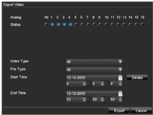
The export function is used to store important recordings on connected external media, such as:
- USB media
- USB HDD
-
DVD writer
-
Enter the parameters (see page 33).
- Click on "Details" to limit the search.
- Click on Export to start the search. The results screen is displayed.

- The file size of the individual recording and the total size of all found recordings are displayed.
- Click on Export to access the export screen.

- Select the connected medium used for data storage from the drop-down menu.
- If the medium is not displayed, click on Refresh.
- If the medium is still not displayed, disconnect it from the device and reconnect the medium again. See also the manufacturer's specifications.
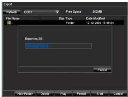
- Click on Start to start the export process. The progress of the export process is then displayed.
i
Note
After the storage process is completed, the data on the medium can be selected and played on the player (which was also backed up). In this way, you can check whether the export has been made successfully.
Manual Alarm
i
Note
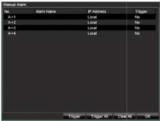
The menu is used to check the recording settings in the event of an alarm, to trigger alarm outputs manually and to test the settings. You can then check and correct your settings in the playback screen.
- Select the camera by clicking the corresponding line.
- Click on Trigger to switch on the alarm manually. Trigger then changes to No for this camera.
- Confirm the prompt by pressing OK.
- When Trigger All is selected, then all alarms are switched on manually.
- Click on Clear All to switch off all alarms simultaneously.
HDDs
i
Note
The device manages up to eight 3.5" SATA hard disk drives.
Each of the installed HDDs must be initialised before the device can be used for recording. The device only detects the HDD and its assignment after initialisation has been made.

Warning
All data is deleted from the HDD during initialisation.
Ensure a data backup has been made in good time beforehand.
Installing the HDD
- Disconnect the device from the mains power and open the cover.
- Observe the applicable ESD guidelines when handling electronic devices and ensure they are earthed.
- Do not open the device in rooms with carpets or other surfaces that can become electro statically charged.
- Avoid bodily contact with all components on the PCB.

Warning
If you have questions regarding the information or cannot find the information you need, please contact your maintenance specialist.
- Install the HDD, then connect it.
- Reattach the cover and connect the device to the mains power supply.
- Switch on the device and start the HDD menu.
Initialising the HDD

HDD Management parameters
| “General” tab | |
| Label Shows the | internal connection num-ber |
| Capacity HDD capacity (in GB) | |
| Status Shows the current status of the HDD:Not initialisedNormalError | |
| Property | Redundancy: Works redundantly for data securityRead-only: Read-only protectionR/W: Read and write |
| Type Local: Device HDDNFS: Network HDD | |
| Free Space Shows the approximate free memory for recordings | |
| Group HDD group (1 is preset)Recordings can be assigned to groups | |
| “Set Cameras for HDD Group” tab | |
| Analog Overview of camerasUsed for accessing the selected camera group | |
| IP | Overview of IP camerasUsed for accessing the selected IP camera group |
| Data Backup on HDD Group | 1 to 8 |
i
Note
If the initialised HDD is not displayed, check the connections.
- Select the HDD by checking the corresponding box.
- Start the process by clicking on "Init".
- Confirm the prompt by pressing OK.
- The status bar shows the progress of the initialisation.
- The following appears after the process is complete.

Setting the HDD

i
Note
Define which status the HDD should have:
Read-only: The HDD is write-protected. Recordings are made on the next HDD.

Warning:
If only one HDD is installed and this is set to "Read-only", then the device cannot make recordings.

Redundancy:
At least two HDDs are installed.
The redundant HDD makes an extra copy of the recordings. This is used as a data backup.
• R/W
At least one HDD must have the R/W status
(Read/Write). Otherwise, no recordings are possible.
Adding a network HDD

Note
Pay attention to the network information on page 49.
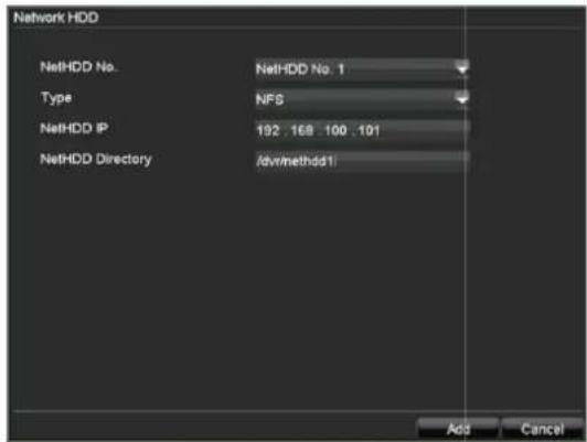
| Parameter Setting | |
| NetHDD No. 1–8 | |
| Type NFS | |
| NetHDD IP | IP address |
| NetHDD Directory | Directory name |
Enter the parameters to add a network HDD.

Note
The network must be active to record on the network HDD.
For example, check whether a night service or similar is installed which switches off network activity.
Checking the HDD status
The status of each HDD can be checked in the "Maintenance" menu. S.M.A.R.T. information (Self-Monitoring, Analysis and Reporting Technology) is stored in the log data.
- Call up the log file and search according to the information/S.M.A.R.T. HDD (see page 47).
Setting up the HDD alarm
You can specify alarms to inform you of HDD errors.
- To do this, call up "Exception" in the "System Settings" menu (see page 44).
System Settings

Note
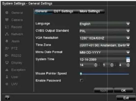
The "System Settings" menu is used to manage all device settings.

Warning
Ensure that the date and time are set correctly. IMPORTANT:
Subsequent changes to the settings can lead to data loss!
Ensure a data backup has been made in good time beforehand.
Overview
| Menu Setting | Page | |
| General | Language, video, time, date, mouse pointer, password, time zones and other settings | |
| Camera | Adding, changing and selecting analogue and IP cameras | 40 |
| Record | All recording settings (type, resolution, motion detection, schedule etc.) | 24 |
| Network Re | quired network settings (manual IP, DHCP, PPPOE, DDNS etc.) and network status overview | 49 |
| Alarm | Assignment and parameterisation of detectors to alarm inputs and relay outputs | 54 |
| PTZ | PTZ hardware parameters and assignment to camera inputs | 28 |
| Menu Setting | Page | |
| RS232 | Parameters on the serial connec- 43 tion | |
| Display | Display settings and assignment of the event output | 23 |
| Exception | Behaviour of the device in exceptional cases (HDD full, network disconnected etc.) | 44 |
| User | Adding and changing users, as-signing authorisation rights | 44 |
| UVV | Loading of settings required for operation according to accident prevention guidelines (UVV) | 45 |

Note
Pay attention to the instructions in the corresponding sections.
General Settings
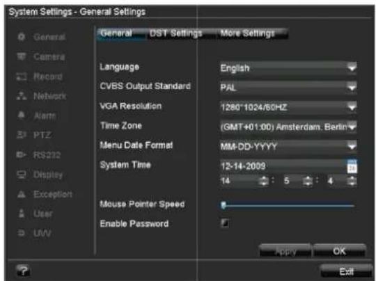
| “General” tab Setting | |
| Language | Language on the OSD |
| CVBS Output Standard | PAL / NTSC |
| VGA Resolution | Resolution on the monitor |
| Time Zone | GMT (Greenwich Mean Time) |
| Menu Date Format | MM-DD-YYYY, DD-MM-YYYY, YYYY-MM-DD |
| System Time | Date and time |
| Mouse Pointer Speed | Set on the scroll bar (left = low speed; right = high speed) |
| Enable Password | Box not checked: No passwordBox checked: Password must be entered in order to use the menu |
| “DST Settings” tab | Setting |
| DST Activated when box is checked | |
| From / To Date of DST start / end | |
| DST Bias Daylight Saving Time Bias: Correction of the DST to the reference time | |
| “More Settings” tab | Setting |
| Device Name Unique specification of the device | |
| Device Number Used for unique identification when using remote control | |
| Monitor Brightness Scroll bar (left = darker; right = brighter) | |
| Transparent 1:1:3:1, 1:3 or Non-transparent – used for managing the display of the OSD in front of the background image | |
| Menu Dwell Time 1 to 30 minutes – regulates how long the menu is shown | |
| Activate Event Note Displays a symbol at the bottom-left of the live image when an event occurs | |
| Activate Monitor Note Shows the monitor ID at the bottom-left(M = main monitor, A = auxiliary monitor) | |
| Main/AUX CVBS Scaling Video signal scaling on the AUX monitorBox checked / not checked | |
System Settings: Camera

All cameras or signal inputs (see page 3) are displayed in the "Camera Management" overview.
| Name Meaning | |
| Camera No. Signal input | |
| Camera Name Specified camera name | |
| IP Camera Address | Local (connected to the device) or IP address on network cameras |
| Port N/A (connected to the device) or port number on network cameras | |
| Status Enable / Disable | |
-
Click on Status and activate or deactivate the connected cameras.
-
Confirm with OK.

Note
The device must be rebooted in order to activate the camera.
Pay attention to the network settings (see page 49).
-
Select the camera by clicking the corresponding line.
-
Select Set to define a new camera connection.

| “General” tab Setting | |
| Camera Selection of the camera (only previously activated cameras can be selected) | |
| Camera Name Clear identification of the camera (e.g. right car park, front entry gate etc.) | |
| Display Camera Name | Box checked / not checked |
| Display Date Box checked / not checked | |
| Display Week Box checked / not checked | |
| Date Format Format of the displayed date | |
| Time Format 12-hour / 24-hour display | |
| OSD Display OSD transparent, flashing, non-transparent etc. | |
| OSD Display Position | Screen position of the OSD |
| Copy To Selection of whether the settings should be copied to another camera (and if so, to which camera) | |
| Record See page 24 | |
- Select "Advanced" to specify the other camera settings.

| “Advanced” tab Setting | |
| Camera Selection of the camera (only previously activated cameras can be selected) | |
| Image Settings Brightness, contrast, saturation and colour | |
| Mask Setting up of zones | |
| Tamper Detection | Setting up of zones |
| Motion Detection | Setting up of zones |
| “Advanced” tab Setting | |
| Video Loss Detection | Activation according to the definable schedule and notification (display, acoustic alarm, notification of surveillance centre, e-mail, trigger of an alarm output) |
| Copy To | Copies the settings |
Setting up of zones
i
Note
When carrying out camera surveillance, you can define zones that should not be monitored (private zones).
You can also set up zones with special characteristics (e.g. tamper monitoring or motion detection).
-
Activate the zone by checking the corresponding box and clicking on "Area Settings".
-
With the left mouse button held down, pull a frame around the desired zone in the live screen.
natural_image
Exterior view of a modern multi-story building with glass facade and surrounding greenery (no visible text or signage)-
When setting tamper monitoring and motion detection zones, you can open a pop-up menu by right-clicking the mouse. The sensitivity can be set here and the full-screen mode can be activated (for motion detection).
-
To exit the zone settings, right-click the mouse button and select Exit.
i
Note
After applying the settings, the set private zone is displayed as a black rectangle in the image. Zones for tamper monitoring and motion detection are not displayed.
Zones: Schedule and notification
i
Note
You can assign the surveillance parameters individually and control the notification type for tamper monitoring, motion detection and video loss detection.
Schedule
- Select Schedule in the advanced camera settings.
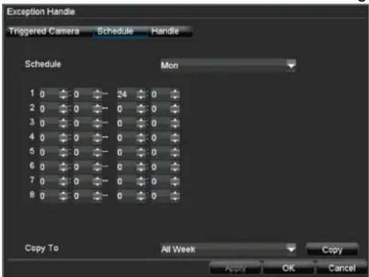
- Select the day and enter the schedule.
i
Note
You can define up to 8 time periods (each from 00:00 to 00:00). The times in the individual periods must not overlap.
-
Select whether the settings should be applied to all days of the week using Copy To and confirm with Copy.
-
Exit the settings by pressing OK.
Notification
- Select Handle in the advanced camera settings.
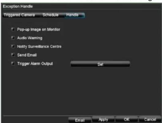
- Enter the notification type:
| Parameter Notification | |
| Pop-up Image on Monitor | Message appears on monitor |
| Audio Warning The device | emits a repeating tone |
| Notify Surveillance Centre | See page 52 |
| Send Email An e-mail is sent to a specific e-mail address (see page 52) | |
| Trigger Alarm Output See page 56 | |
-
Click on Apply to accept the settings.
-
Click on OK to exit the menu.
Adding a network camera
In the "Camera Management" menu, click on "Add".

The available network cameras are shown at the top of the screen.
- If the camera to be added does not appear, click on Refresh.
• Alternatively, you can enter the data for the network camera manually.
| Parameter Setting | |
| IP Camera No. | IP camera number in the DVR |
| IP Camera Address | Unique address of the IP camera within the applied IP address range |
| Manage Port http port of IP camera | |
| Channel No. Channel number | |
| Manufacturer Select the IP protocol of the camera manufacturer | |
| Admin Name Administrator user name | |
| Admin Password | Administrator password |
- After entering the data press OK to add the network camera.

Note
Check the entered values if the network camera does not appear in the overview.
Check the network (see page 49).
Setting the network camera
Open the recording settings and enter the parameters for the network camera (see page 24).
System Settings: Record

Note
See description on page 24.
System Settings: Network

Note
See separate section on page 49.
System Settings: Alarm

Note
See separate section on page 54.
System Settings: PTZ

Note
See description on page 28.
System Settings: RS232
No function.
System Settings: Display

Note
See description on page 23.
System Settings: Exception

i
Note
Enter the trigger under "Exception Type", for example:
- HDD Full
- Disconnected
After doing this, specify the device behaviour as detailed on page 42.
System Settings: User
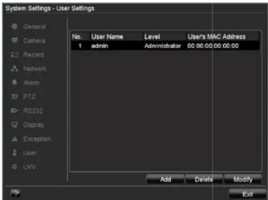

Warning
Note down the admin password.
The following password is preset
"1 2 3 4 5"
You can add new users, delete existing users and change the settings in the "User Settings" menu.
- To add a new user, select Add.
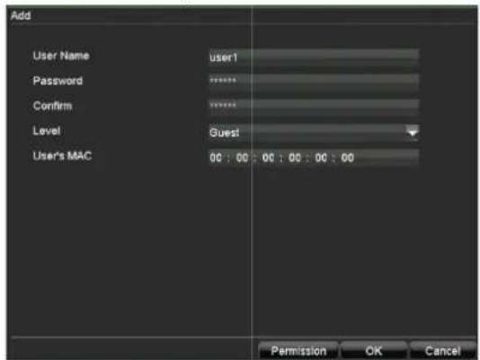
| Parameter Setting | |
| User Name | Unique identification |
| Password | Access code for the device (device management)Note: Change all passwords on a regular basis, using a combination of letters and numbers. Note down all passwords in a safe place. |
| Confirm | Enter the access code again here |
| Level IMPORTANT:More access rights can be set on the Manager level than on the User level. | |
| User's MAC | MAC address of the network adapter on the PC of the corresponding userNote:This limits access to the PC whose MAC address is entered here! |
- Enter the name and password and confirm the password in the field below.
- Select the level and enter the MAC address.

Warning
Pay attention to the instructions below on assigning access rights.
Setting the access rights
- Control the access rights of the user by clicking on "Permission":
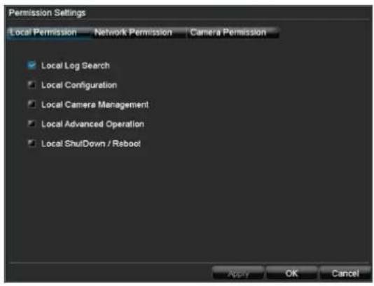
i
Note
The user can make the settings locally (i.e. on the device) or change the parameters.
The user can access the device via the network connection.
The "Camera Permission" tab is used to set access rights for individual cameras (network or local).
- Switch tabs by clicking on the arrows in the tab bar:
| Parameter Setting | |
| Local Per-mission | Local Log SearchLocal ConfigurationLocal Camera ManagementLocal Advanced OperationLocal ShutDown / Reboot |
| Network Permission | Network Log SearchNetwork ConfigurationNetwork Camera ManagementControl Serial ConnectionsVideo Output ControlTwo-way AudioAlarm ControlNetwork Advanced OperationNetwork ShutDown / Reboot |
| Camera Permission | Remote Live ViewLocal Manual RecordingStart Remote RecordingLocal PlaybackRemote PlaybackLocal PTZ ControlRemote PTZ ControlLocal Data Export |
System Settings: UVV

i
Note
Only for TVVR50010 and TVVR50020. Settings are loaded according to accident prevention guidelines (UVV):
• Event recording CIF@25 fps
• Continuous recording CIF@2 fps
- Schedule – 24-hour continuous recording
• Post-alarm recording time = 15 minutes
Maintenance


Note
This menu is used for device maintenance, and should only be operated by experienced users.
| Menu Setting | Pag | e |
| Upgrade Carri es out a firmware upgrade | ||
| Log Search | A search of recordings or in-formation (S.M.A.R.T. HDD status) can be made in the log file according to certain criteria (alarms, exceptions, operation or information). | 47 |
| Default System reset 48 | ||
| Menu Setting | Page | |
| Configuration | Used to export or import the settings | 48 |
| Information Device information (serial number, firmware status etc.) | 48 | |
Upgrading the device


Note
A device upgrade can be made from a USB device or over the network via FTP.
- Copy the upgrade file to the main directory of a USB stick.
-
Connect the USB stick to a USB port on the device.
-
Select the USB port (click on "Refresh", if necessary).
- Select the upgrade file and click on "Upgrade".
- Wait until the device reboots.
- Check the firmware status in the "Maintenance" menu under "Information".

Note
- Upgrades via FTP are made in the same way as detailed above. The PC must be located in the same local network.
- Set up a PC as an FTP server.
- Enter the IP address of the FTP server.
Log Search

i
Note
An event search can be made according to the following main types, events and parameters:
• All
- Alarm
- Exception
- Operation
- Information
| Type Minor type / sub-parameter | |
| All - | |
| Alarm | AllAlarm Input / OutputMotion Detection Begin / EndStart / End Tamper Detection |
| Exception | AllVideo Signal LossVideo Signal ExceptionLogin ErrorHDD FullHDD ErrorIP Address ConflictNetwork DisconnectedData Record FailedIP Camera Connection FailedIP Address Conflict with IP Camera |
| Type Minor type / sub-parameter | |
| Operation | AllSwitch OnShutdownIrregular ShutdownLocal RebootLocal Login / Local LogoutLocal SettingsUSBLocal Recording Begin / EndLocal PTZ ControlLocal File LockedOthers |
| Information | AllHDD InformationHDD S.M.A.R.T.Start RecordStop RecordDelete Obsolete RecordingNetwork HDD Information |
- Select the event you wish to search for in the log, then select the sub-parameter.
- Enter the date and time under "Start Time" and "End Time", then click on Search.
- The results are then displayed:
| Log Search | |||
| Major Type | Start Time | Minor Type | Parameter |
| Information | 12-14-2009 00:00:01 | Stop Record | N/A |
| Information | 12-14-2009 00:00:01 | Start Record | N/A |
| Information | 12-14-2009 00:00:01 | Stop Record | N/A |
| Information | 12-14-2009 00:00:01 | Start Record | N/A |
| Information | 12-14-2009 00:00:01 | Stop Record | N/A |
| Information | 12-12-2009 00:32:30 | HDD S.M.A.R.T | N/A |
| Information | 12-14-2009 01:32:32 | HDD S.M.A.R.T | N/A |
| Information | 12-14-2009 02:32:35 | HDD S.M.A.R.T | N/A |
| Information | 12-14-2009 03:32:37 | HDD S.M.A.R.T | N/A |
| Information | 12-14-2009 04:32:41 | HDD S.M.A.R.T | N/A |
| Information | 12-14-2009 05:32:43 | HDD S.M.A.R.T | N/A |
| Alarm | 12-14-2009 06:07:50 | Motion Detection Begin | N/A |
| Information | 12-14-2009 06:07:50 | Start Record | N/A |
| Alarm | 12-14-2009 06:07:56 | Motion Detection End | N/A |
| Information | 12-14-2009 06:08:03 | Stop Record | N/A |
| Alarm | 12-14-2009 06:12:18 | Motion Detection Begin | N/A |
| Information | 12-14-2009 06:12:18 | Start Record | N/A |
- Click on Details to see more detailed information.
- Click on Play to start the recording for the event, when necessary.
- Click on Export to back up the log file on a USB medium.
Default Settings
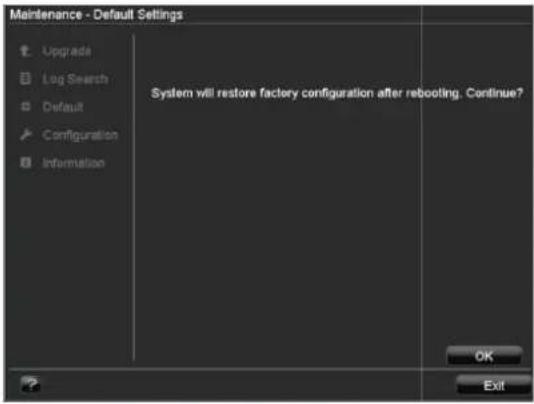

Note
In this process, the device is reset to the factory default settings.

Warning
All settings made since the start of operation are deleted (cameras, recording settings, PTZ, alarms etc.)!
Avoid data loss by backing up the settings in advance. These can be imported again following the system reset.
Import / Export Configuration
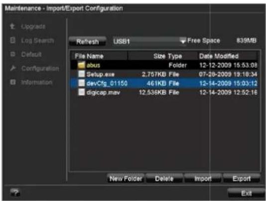

Note
The configuration data contains all settings made on the device since the start of operation. This data can be saved on a USB medium. You can then configure another device identically, for example.
Information


Note
The technical data of the device is displayed in the information menu.
This can be useful for support queries, for example.
Shutdown


Note
- Select "Lock" to lock the operating menu.
- Select "Shutdown" to switch off the device.
- Select "Reboot" to reboot the system (switch off and back on).
See also page 16.
Network
General information
Correct network settings are essential in the following cases:
- When using network cameras (IP cameras)
- When using remote control of the device and surveillance over your server

Note
Please read the following basic instructions before setting up the device.
A network is a connection of at least two network-capable devices.
Transmission types:
- Wired networks (e.g. CAT5 cable)
- Wireless networks (WLAN)
- Other transmission types (Powerline)
All systems have certain similarities, but can also differ in many ways.
Terms and definitions
An overview of relevant terms when using the device in a network can be found below.
| Parameter Setting | |
| IP address An IP address is the unique address of a network device within a network.This address may only appear once within a network. Certain IP address ranges are reserved for public networks (e.g. the Internet). | |
| Private address range | e.g. 10.0.0.0 – 10.255.255.255Subnet mask: 255.0.0.0172.16.0.0 - 172.31.255.255Subnet mask: 255.255.0.0192.168.0.0 - 192.168.255.255Subnet mask: 255.255.255.0 |
| Subnet mask | A subnet mask is a bit mask used for making decisions and assignments during routing.255.255.255.0 is the standard subnet mask in home networks. |
| Gateway | A gateway is a network device which allows all other network devices to access the Internet.This can be the computer connected to the DSL modem or – usually – the router or access point within the network. |
| Parameter Setting | |
| Name server | The name server is responsible for assigning a unique IP address to a web address or URL (e.g. www.google.de). Also known as DNS (Domain Name Server).When a domain name is entered into a browser, the DNS searches for the corresponding IP address of the server and forwards the query on.The IP of the provider's DNS can be entered here. However, it is often sufficient to select the IP of the gateway. This then forwards the queries independently to the provider DNS. |
| DHCP | The DHCP server automatically assigns the IP address, subnet mask, gateway and name server to a network device.DHCPs are available in current routers.The DHCP service must be specially set and activated (see the corresponding manual for more information).Note:When using fixed IP addresses and a DHCP server, make sure that the fixed IP addresses are outside the address range assigned by DHCP. Otherwise, problems could occur. |
| Port | A port is an interface used for communication by different programs. Certain ports are fixed (21: Telnet, 23: FTP), whilst others can be freely selected. Ports are important for different applications (e.g. external access to the device over a browser). |
| MAC address | The MAC address (Media Access Control or Ethernet ID) is the specific hardware address of the network adapter.This is used for the unique identification of the device in a computer network. |
Network layout
The device must be physically connected to the network over a CAT5 cable (see connections on page 3).
Note
Pay attention to the specific information and instructions on the network devices.
Several switches, routers and access points can be connected to each other. Firewalls and other security software can affect the network.

Warning
When using a router, the network clients (e.g. the recorder) can be connected to the Internet and vice versa.
Make sure to use protective measures to prevent unauthorised external access (e.g. firewall, changing passwords, changing ports)!
Network configuration
The device must be configured using the "System Settings" and "Network Settings" menus.

| Parameter Setting | |
| NIC Type | Set the transmission speed of the installed network card here.Tip: 10M/100M/1000M |
| DHCP Check | the box if the IP addresses are assigned dynamically via DHCP in the network.DHCP activated: Subsequent entry fields are inactive (parameters assigned via DHCP).Note:If the IP addresses are assigned manually, ensure that DHCP is not active (box not checked). |
| IP Address | Address of the network device in the network (manual assignment) |
| Subnet Mask | Usually 255.255.255.0 |
| Default Gateway | Address of the gateway for Internet access |
| Preferred DNS Server | Address of the Domain Name Server (usually the IP address of the gateway) |
| Alternate DNS Server | IP address of the alternative DNS server |
| MAC Address | Hardware address of the installed network card |
Advanced network configuration
Specify further parameters for the network configuration in the "Advanced" tab.

| Parameter Setting | |
| PPPOE PPPOE | E is used on ADSL connections and when using modems in Germany.Click on “Set” to enter the access data (ID and password) for your provider. |
| DDNS Server | for Dynamic Domain Name System management. Used for updating host names or DNS entries |
| NTP Network | Time ProtocolServer for time synchronisation |
| HOST / OTHERS | Communication and HTTP port. |
| Email Used to | specify the e-mail settings which are sent as an e-mail to a specific address in the event of an alarm. |
Setting up PPPOE manually
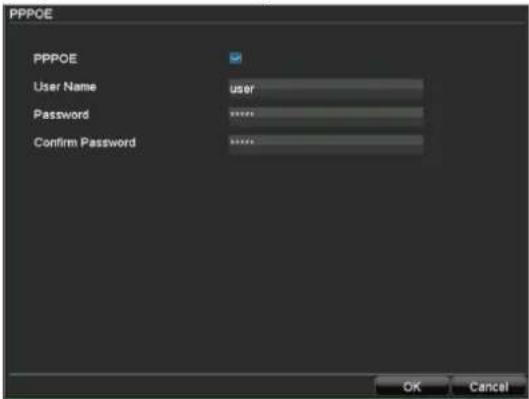
- Check the PPPOE box, enter the user name (Internet access ID) and password, then confirm the password.
- Apply the settings by pressing OK.
Setting up DDNS manually

- To use the ABUS DDNS function, you must first set up an account under www.eytronserver.com. Please note the FAQs on the website when doing this.
- Check the DDNS box, enter "ABUS DDNS" as the "DDNS Type", then enter www.eytronserver.com or "62.153.88.107" under "Server Address".
- Apply the settings by pressing OK. The IP address of your Internet connection is now updated on the server every minute.
Setting up NTP manually
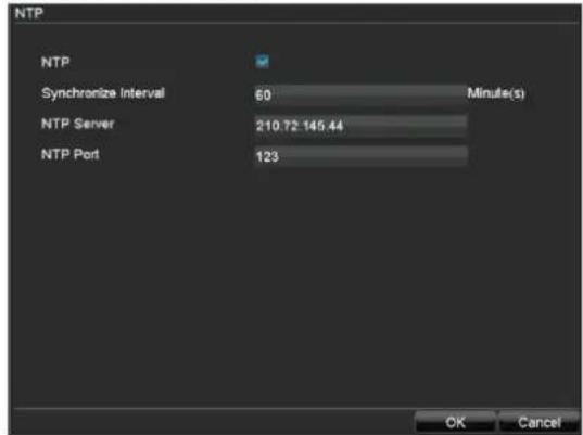
i
Note
The recorder can synchronise the time with an external server. Several server addresses are available on the Internet for this purpose.
- Check the NTP box, then enter the interval at which the synchronisation should be made again. Enter the IP address of the NTP server and the NTP port.
- Apply the settings by pressing OK.
Setting the HOST / OTHERS
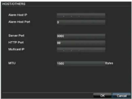
| Parameter Setting | |
| Alarm Host IP No function | |
| Alarm Host Port No function | |
| Server Port Port for data communication | |
| HTTP Port Port for web server | |
| Multicast IP In order to minimize traffic you can enter a Multicast IP. The IP address has to match the IP address of the PC running the CMS software. | |
| MTU Describes the max. size of the largest protocol data . | |

Note
Server port 8000 and
HTTP port 80 are the standard ports for remote clients and remote Internet browser access.
Setting up an e-mail address
In the event of an alarm, the device can send a message by e-mail. Enter the e-mail configuration here:

| Parameter Setting | |
| Server Authentication | Check the box when authentication is made on the server of the Internet provider |
| User Name E-mail account at the provider | |
| Password Password connected to the e-mail account | |
| SMTP Server SMTP server address of the provider | |
| From Name Name of the sender | |
| From Email Address | Corresponding e-mail address for the e-mail account |
| Select Recipients | Select three possible recipients for the e-mail |
| To Name Enter the name of the recipient here | |
| To Email Address | Enter the e-mail address of the recipient here |
| “Advanced” tab | Setting |
| Attached JPEG File | Check the box when camera images should also be sent with the e-mail as photo files |
| Interval Select the interval between the individual recordings (2 to 5 seconds) | |
| SMTP Port Enter the SMTP port here(Default: 80) | |
| SSL | Check the box to activate the e-mail encryption |
- Enter the parameters of the e-mail notification.
- Click on Test to send a test e-mail.
i
Note
The device sends an e-mail to the specified recipients.
If the e-mail is not received, check the settings and correct them.
If necessary, check the spam filter of your e-mail client.
Network Status
Click on the "Network Status" tab to see an overview of the current network configuration.

| Parameter Setting | |
| DHCP Status: | When DHCP is active, the corresponding parameters are shown. “N/A” is displayed when DHCP is inactive. |
| PPPOE Status: | Shows whether an Internet connection is established during manual set-up.Also displays the IP address, subnet mask and defined default gateway.Note: If a router is used which is set up as the gateway / DSL modem, then the PPPOE settings of the router are used.The display then shows “N/A”. |
Alarm
Alarm overview
The alarm settings regulate the type of camera surveillance in a detailed fashion and control the device behaviour (for example, in the event of motion detection or video signal loss).
- Open the "System Settings" menu and click on "Alarm" in the menu on the left.

The available alarm detectors are then shown in the overview. The signals on these detectors can then be managed via the corresponding alarm inputs.
Alarm Input
- Select the alarm detector by marking the corresponding line and then clicking Set.

| Parameter Setting | |
| Alarm Input No. | Select the alarm input to make the settings |
| Alarm Name Enter | a clear description here (e.g. door contact on warehouse) |
| Type N.O.: Normally open circuitN.C.: Normally closed circuit | |
| Parameter Setting | |
| Setting Check the box | box to make exception settings and notification settings (see page 42). |
| PTZ Camera Assignment of the PTZ camera to the camera input | |
| Preset | Check / uncheck the box |
| Patrol | Select the preset, patrol or pattern from the drop-down menu |
| Pattern | |
| Copy To Copies the settings | |
- Assign the alarm input in the drop-down menu.
- Enter the alarm name.
- Select the type of alarm encoder from the drop-down menu:
• N.O.: Triggers an alarm when closed
• N.C.: Triggers an alarm when opened
- Check the "Setting" box and click Handle.
Each triggered alarm you can handle individually:
Handle:
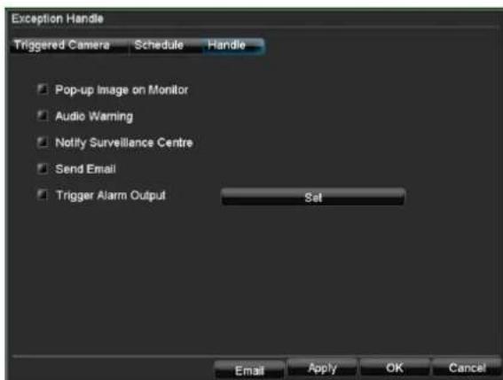
| Parameter Setting | |
| Pop-up Image on Monitor | A message appears on the monitor. |
| Audio Warning The device | emits a repeating tone. |
| Notify Surveillance Centre | Sends an alarm signal to a PC with ABUS CMS software. The software must be enabled and the recorder set to surveillance mode on the PC. |
| Send Email An e-mail is sent to a specific e-mail address (see page 52). | |
| Trigger Alarm Output See | page 56. |
Schedule:
Here you can define in which period of time the reaction to the alarm input shall be handled.
Triggered Camera:

| Parameter Setting | |
| Record Using this | is parameter, you can select which cameras should be used for recording after the alarm input is triggered. |
| Enable Schedule | Using this parameter, you can select on which cameras the schedule should be activated. For example, if you have installed the ABUS IP alarm module, then you can use the Secvest Key to activate guard mode in the recorder when exiting the premises. The recording mode (duration, motion detection, alarm) stored in the schedule is then used. In this way, you can activate the recorder independently from the schedule and prevent false alarms.Ensure that the schedule is not activated initially so that it is not disarmed during activation. |
Alarm Output
- Click on "Alarm Output" in the "Alarm Settings" menu.
| Parameter Setting | |
| Alarm Output No. S | Select the alarm output to make the settings |
| Alarm Name Enter a clear description here (e.g. siren in warehouse) | |
| Length Length of the activated alarm | |
| Schedule Time-dependent control of the alarm output | |
| Copy To Copies the settings | |
- Assign the alarm output in the drop-down menu.
- Enter the alarm name.
- In the drop-down menu, enter the interval between the alarm input message and the signal output on the relay.
- Select the day and enter the schedule (see page 42).
- Copy the settings to other alarm inputs if the parameters match or if so required.
i
Note
If a network camera is used, then this must be set up correctly and network access must be possible.
Pay attention to the information under Manual Alarm on page 36.
IP alarm module
You can add up to three ABUS IP alarm modules (CASA10010) here. After successfully connecting via the network, two alarm inputs and two alarm outputs are added to each of the "Alarm Input" and "Alarm Output" tabs. The short name of the inputs is
U1<-1 / U1<-2, whilst the short name of the outputs is U1->1 / U1->2.
Click on "Add" to configure an ABUS IP alarm module.

| Parameter Setting | |
| UVM Name A unique name for the IP alarm module can be entered here. | |
| IP Address Enter the IP address of the IP alarm module here. | |
| Manage Port Enter the port (default: 8000) of the IP alarm module here. | |
| Admin Name Enter the user name of the IP alarm module here (user must have administrator rights). | |
| Password Enter the password of the user specified above here. |
After a successful connection two virtual alarm in- and outputs are added. These can only be switch by network.
i
Note
Please refer to the homepage (www.abus-sc.com) to find further installation instructions in the download section of the ABUS IP Alarm Module (CASA10000).
Troubleshooting
Before calling the Service department, read the following information to determine the possible cause of a malfunction.
| Malfunction Cause Solution | ||
| No power Mains cable not connected Connect the mains cable securely to the socket | ||
| Power switch set to OFF Turn the power switch to ON | ||
| No current in the power socket Use another device on the socket, where necessary | ||
| No image Screen not set for reception Set the correct video input mode until an image from the recorder appears | ||
| Video cable not connected properly Connect the video cable securely | ||
| Connected modem is switched off Switch on the monitor | ||
| Camera images black and white and blurred, despite colour camera being installed | If no cameras are connected when the recorder is started, then the recorder is started automatically in NTSC mode. If only PAL colour cameras are connected, then these are displayed as black and white and blurred | Connect the cameras before starting the recorder. The recorder automatically detects whether a PAL or NTSC signal is present and switches to the correct mode. You can set the mode (see page 39) |
| No sound Audio cables not connected properly Connect the audio cables securely | ||
| Devices connected over the audio cables are not switched on | Switch on the devices connected over the audio cables | |
| Audio connection cable is damaged Replace the cable | ||
| HDD is not working Connection cables not connected properly Connect the cables securely | ||
| HDD defective or not system-compatible Replace with a recommended HDD | ||
| USB port not working | Device not supported | Connect a compatible USB medium (USB 2.0) |
| USB hub is in use | Connect the USB medium directly | |
| Network access not possible | Network cable connections are loose | Connect the network cable |
| Network settings are incorrect (DHCP, IP address etc.) | Check the network configuration and correct it, when necessary (see page 50) | |
| Remote control is not working | Batteries inserted with the wrong polarity or are empty | Replace the batteries. To control the device with the remote control, point it at the remote control sensor on the device |
| Remote control too far away from the recorder | Use the remote controller within 7 metres from the device | |
| Signal blocked by obstruction between the remote control and recorder | Remove the obstruction | |
| Lighting too bright or fluorescent tubes in use? | Switch off strong fluorescent lighting in the immediate vicinity | |
| Recording not possible | No HDD or HDD is not initialised | Install and initialise the HDD |
| Sudden deactivation of the device | Temperature inside the device is too high | Clean the device and remove any obstructions from the ventilation area |
Device cleaning and care
Note
- Your device requires no maintenance.
- Protect the device from dust, dirt and moisture.
Index
Access rights 45
Address range 49
Admin 44
Admin Password 18, 44
Alarm 25, 47, 54
Alarm Input 54
Alarm Out 56
Alarm output 42
Alarm Output 56
Audible warning signal 42, 55
Authentication 52
AUX monitor 22
Batteries 63
Camera
IP address 40
Network camera 42
Setting the network camera 43
Setting up zones 41
Zone schedule, notification 42
Camera display Views 21
Camera keys 17
Camera output Setting 23
Camera settings 40
Channel 42
Configuration 48
Connections 14
Control panel 26, 27 PTZ 28
PTZ pop-up menu 28
CVBS Output Standard 39
DDNS 51
Default Gateway 50
Device menu 32
Device overview 3
DHCP 49
Disposal 63
DST Bias 40
DVR status LED 17
Dwell Time 40
Email 52, 55
E-mail 42
Enable Password 39
Encoding 24
Exception 44
Frame rate 24
FTP 46
FTP server 46
Gateway 49
General Settings menu 39
HDD 66
Alarms 38
Capacity 62
Initialising 37
Network HDD 38
Parameters 37
Safety 66
Setting 37
Status 38
HDDs 36
Host PC 52
Information 48
Installation location 10
IP address 42, 49
Live view 21
Settings 23
Log Search
Alarm 47
MAC address 44, 49
Maintenance 46
Upgrade 46
Manual Alarm 36
Manual Record 33
Mask 41
Menu 21, 32
System Settings 39
Menu overview 32
Monitor
Displays 17
Motion detection 25
Motion Detection 41
Mouse
Pop-up menu 21
Mouse operation 15
N.C. 54
N.O. 54
Name server 49
Network 49
Advanced configuration 50
Configuration 50
Email 52
Status 53
Network camera 43
Network Status 53
Notification 42
NTP 51
On-screen keyboard 16
Operating elements 13
Playback 21, 26
Advanced video
search 27
Control panel 26
From live view screen 27
Screen 26
Video search 26
Pop-up menu 21
Port 42, 49
Post-alarm 24
PPPOE 51
Pre-alarm 24
Preset 28, 54
PTZ 21
Patrol 28
Patrol Settings 30
Pattern 28
Pattern Settings 31
Preset 28
Preset Settings 29
Settings 29
PTZ Camera 54
PTZ control 28
Reboot 48
Recording
Advanced settings 24
Manual 25
Schedule 25
Settings 24
Remote alarm 52
Remote control 4, 14
Reset 48
Resolution 24
RS232 43
Schedule 42
Scope of delivery 12
Setting menu 39
Settings
Camera 40
General 39
Setup 32
Setup wizard 18
ShutDown 48
Shutting down 16
SMTP 52
Status displays 17
Status symbols 21
Stop Auto-switch 22
Storage capacity 62
Stream 24
Subnet mask 49
Surveillance centre 42
Switching off 16
Switching on 16
Symbols 9
Synchronising 51
System Time 39
Tamper Detection 41
Time Zone 39
Upgrade 46
User 44
UVV 45
VGA Resolution 39
Video Export 35
Video Loss Detection 41
Video output 23
Video quality 24
Video Search 33
Parameters 33
Results 34
Voice output 17
Zones 41
Zoom 22
Technical data
Subject to alterations and errors. The dimensions are approximate values.
| ABUS digital recorder TVVR$0011 TVVR50021 | ||
| Video compression | H.264 | |
| Hybrid-compatible | √ | |
| Camera inputs | 8 x BNC (1.0 V p-p, 75 Ω) 16 x BNC | (1.0 V p-p, 75 Ω) |
| Camera outputs | 8 x BNC (1.0 V p-p, 75 Ω) - TVAC41920 required | 16 x BNC (1.0 V p-p, 75 Ω) - TVAC41930 required |
| IP cameras | 8 x IP @ VGA / 4 x IP @ 1280 x 720 / 4 x IP @ 1600 x 1200 | |
| IP camera protocols | ABUS | |
| Monitor outputs | Monitor: 1 x BNC (1.0 V p-p, 75 Ω), 1 x HDMI, 1 x VGA Spot: 1 x BNC (1.0 V p-p, 75 Ω) | |
| Operating mode | Triplex | |
| Resolution (live view) | PAL: 704 x 576 (4CIF), NTSC: 704 x 480 (4CIF) VGA: 1024 x 768 / 60 Hz, 1024 x 768 / 70 Hz, 1280 x 1024 / 60 Hz HDMI: 1920 x 1080 / 30 Hz | |
| Resolution @ frame rate per camera (recording) | PAL: NTSC: 352 x 288 (CIF) @ 25 fps 352 x 240 (CIF) @ 30 fps 704 x 288 (2CIF) @ 12 fps 704 x 288 (2CIF) @ 12 fps 704 x 480 (4CIF) @ 6 fps | |
| Total frame rate | PAL: 200 fps, NTSC: 240 fps PAL: 400 fps, NTSC: 480 fps | |
| Compression levels | 6 | |
| Pre-alarm/post-alarm memory | 0-30 sec. / 5-900 sec. | |
| Storage medium | 8 x SATA HDD | |
| Data backup | 3 x USB 2.0 | |
| Views | 1 / 4 / 9 1 / 4 / 9 / 16 | |
| Recording modes | Manual, schedule, motion detection, alarm, motion detection and alarm, motion detection or alarm | |
| Search modes | By event, date and time | |
| Alarm inputs (NO/NC) | 16 16 | |
| Alarm outputs | 4 (Loading capacity: 12VDC/1A) | |
| User levels | 2 (max. 31 users) | |
| Network connection | RJ45 10/100/1000 Mbps | |
| Parallel network access | 64 camera connections | |
| Network functions | Live view, playback, data export, settings | |
| DDNS | √ | |
| NTP | √ | |
| PTZ control | RS-485 | |
| PTZ protocols | PELCO-D, PELCO-P, Samsung, LG-MULTIX | |
| Alarms | Acoustic warning, OSD signal, e-mail | |
| Audio | Audio In: 8 x Cinch (2.0 V p-p, 1000 Ω) Audio Out: 2 x Cinch (600 Ω) | Audio In: 16 x Cinch (2.0 V p-p, 1000 Ω) Audio Out: 2 x Cinch (600 Ω) |
| Control | Mouse, remote control (not included) | |
| Software | Client software | |
| OSD languages | German, English, French, Dutch, Danish | |
| Power supply | 100-240 VAC, 6.3 A, 50-60 Hz | |
| Power consumption | 70 W (without HDD) | |
| Operating temperature | -10 °C-+55 °C | |
| Dimensions (WxHxD) | 450 x 441 x 90 mm | |
| Weight | ≤ 8 kg (without HDD) | |
| Certification | CE | |
| ABUS digital recorder TVVR60010 TVVR60020 | ||
| Video compression | H.264 | |
| Hybrid-compatible | √ | |
| Camera inputs | 8 x BNC (1.0 V p-p, 75 Ω) 16 x BNC | (1.0 V p-p, 75 Ω) |
| Camera outputs | 8 x BNC (1.0 V p-p, 75 Ω) - TVAC41920 required | 16 x BNC (1.0 V p-p, 75 Ω) - TVAC41930 required |
| IP cameras | 8 x IP @ VGA / 4 x IP @ 1280 x 720 / 4 x IP @ 1600 x 1200 | |
| IP camera protocols | ABUS | |
| Monitor outputs | Monitor: 1 x BNC (1.0 V p-p, 75 Ω), 1 x HDMI, 1 x VGA Spot: 1 x BNC (1.0 V p-p, 75 Ω) | |
| Operating mode | Triplex | |
| Resolution (live view) | PAL: 704 x 576 (4CIF), NTSC: 704 x 480 (4CIF) VGA: 1024 x 768 / 60 Hz, 1024 x 768 / 70 Hz, 1280 x 1024 / 60 Hz HDMI: 1920 x 1080 / 30 Hz | |
| Resolution @ frame rate per camera (recording) | PAL: NTSC: 352 x 288 (CIF) @ 25 fps 352 x 240 (CIF) @ 30 fps 704 x 288 (2CIF) @ 25 fps 704 x 288 (2CIF) @ 30 fps 704 x 480 (4CIF) @ 30 fps | |
| Total frame rate | PAL: 200 fps, NTSC: 240 fps PAL: 400 fps, NTSC: 480 fps | |
| Compression levels | 6 | |
| Pre-alarm/post-alarm memory | 0-30 sec. / 5-900 sec. | |
| Storage medium | 8 x SATA HDD | |
| Data backup | 3 x USB 2.0 | |
| Views | 1 / 4 / 9 1 / 4 / 9 / 16 | |
| Recording modes | Manual, schedule, motion detection, alarm, motion detection and alarm, motion detection or alarm | |
| Search modes | By event, date and time | |
| Alarm inputs (NO/NC) | 16 16 | |
| Alarm outputs | 4 (Loading capacity: 12VDC/1A) | |
| User levels | 2 (max. 31 users) | |
| Network connection | RJ45 10/100/1000 Mbps | |
| Parallel network access | 64 camera connections | |
| Network functions | Live view, playback, data export, settings | |
| DDNS | √ | |
| NTP | √ | |
| PTZ control | RS-485 | |
| PTZ protocols | PELCO-D, PELCO-P, Samsung, LG-MULTIX | |
| Alarms | Acoustic warning, OSD signal, e-mail | |
| Audio | Audio In: 8 x Cinch (2.0 V p-p, 1000 Ω) Audio Out: 2 x Cinch (600 Ω) | Audio In: 16 x Cinch (2.0 V p-p, 1000 Ω) Audio Out: 2 x Cinch (600 Ω) |
| Control | Mouse, remote control (not included) | |
| Software | Client software | |
| OSD languages | German, English, French, Dutch, Danish | |
| Power supply | 100-240 VAC, 6.3 A, 50-60 Hz | |
| Power consumption | 70 W (without HDD) | |
| Operating temperature | -10 °C-+55 °C | |
| Dimensions (WxHxD) | 450 x 441 x 90 mm | |
| Weight | ≤ 8 kg (without HDD) | |
| Certification | CE | |
HDD storage capacity
In addition to the actual storage capacity of the installed HDD, the required storage space for recording and surveillance depends on the set resolution and frame rate of the recording.
Continuous recording, 1 x 1 TB HDD:
| Number of cameras | Resolution | FPS | Recommended bit rate | Recording time |
| 8 | CIF 25 | 512 | 20 days, 14 hours | |
| 8 | 2CIF 12 | 512 | 20 days, 14 hours | |
| 8 | 4CIF 6 | 512 | 20 days, 14 hours | |
| 8 | 2CIF 25* | 1024 | 10 days, 7 hours | |
| 8 | 4CIF 25* | 2048 | 5 days, 3 hours | |
| 16 | CIF 25 | 512 | 10 days, 7 hours | |
| 16 | 2CIF 12 | 512 | 10 days, 7 hours | |
| 16 | 4CIF 6 | 512 | 10 days, 7 hours | |
| 16 | 2CIF 25* | 1024 | 5 days, 3 hours | |
| 16 | 4CIF 25* | 2048 | 2 days, 13 hours |
30 days continuous recording:
| Number of cameras | Resolution | FPS | Recommended bit rate | Number of HDDs |
| 8 | CIF 25 | 512 | 3 x 2 TB | |
| 8 | 2CIF 12 | 512 | 3 x 2 TB | |
| 8 | 4CIF 6 | 512 | 3 x 2 TB | |
| 8 | 2CIF 25* | 1024 | 3 x 1 TB | |
| 8 | 4CIF 25* | 2048 | 6 x 1 TB | |
| 16 | CIF 25 | 512 | 3 x 1 TB | |
| 16 | 2CIF 12 | 512 | 3 x 1 TB | |
| 16 | 4CIF 6 | 512 | 3 x 1 TB | |
| 16 | 2CIF 25* | 1024 | 6 x 1 TB | |
| 16 | 4CIF 25* | 2048 | 6 x 2 TB |
On the included CD you can find a program in order to calculate the required amount of memory. In addition you find this software for download on our homepage together with the ABUS CMS software.
Disposal
Information on the EU directive on waste electrical and electronic equipment
To protect the environment, do not dispose of the device with domestic waste at the end of its service life. It can be disposed of at one of the appropriate collection points in your country. Please obey your local regulations when disposing of material.

Dispose of the device in accordance with EU directive 2002/96/EC – WEEE (Waste Electrical and Electronic Equipment). If you have any questions, please contact the department of your local authority which is responsible for waste disposal. Used equipment can be disposed of, for example, by your local or municipal authority, the local waste disposal company or your dealer.
Information on handling batteries
- Always insert batteries with the cor rect polarity. Never attempt to recharge the batteries supplied and do not throw them into naked flames under any circumstances. Do not use different batteries at the same time (old and new, alkaline and zinc-carbon etc.).
Remove the batteries if the device is not used for a long period of time. If used improperly, there is a risk of explosion and leaking batteries! - Take environmental protection into account – used batteries should not be disposed of in domestic waste! They must be taken to a collection point for used batteries.
- Make sure that batteries are kept away from small children. Children may put batteries in their mouths and swallow them. This can cause serious harm to their health. If this happens, consult a doctor immediately.
-
Do not charge normal batteries, heat them up or throw them into naked flames (they may explode).
-
Change low batteries in good time.
- Always change all the batteries at the same time and use batteries of the same type.

Important
Leaky or damaged batteries can cause chemical burns on contact with the skin.
▶ In this case, wear protective gloves.
▶ Clean the battery compartment with a dry cloth.
Important information on disposing of batteries
Your product uses batteries which are subject to the European directive 2006/66/EC and may not be disposed of with domestic waste.
Find out about the regulations for the separate collection of batteries which apply in your country.
Proper disposal of batteries helps prevent harm to health and the environment.
Batteries that contain harmful chemicals are labelled with these signs:

Pb = battery contains lead
Cd = battery contains cadmium
Hg = battery contains mercury
Information on the European RoHS directive
The device complies with the RoHS directive.
Compliance with the RoHS directive means that the product or component does not contain more than the following maximum concentrations of the following substances in homogeneous materials, unless the substance is part of an application that is excluded from the RoHS directive:
a) 0.1% lead (by weight)
b) Mercury
c) Hexavalent chromium
d) Polybrominated biphenyl (PBB) and polybrominated diphenyl ether
e) 0.01% cadmium (by weight)
Glossary
Overview of specialist terms
1080i
HDTV image signal with 1080 pixels and interlaced display.
16:9
Cinematographic aspect ratio on widescreen displays.
720p
HDTV image signal with 1280 x 720 pixels and progressive display.
CIF
Common Intermediate Format
Originally planned for converting PAL to the NTSC standard. CIF corresponds to a video resolution of 352 x 288 pixels (2CIF = 704 x 288 pixels; 4CIF = 704 x 576 pixels).
CINCH
Socket type used for analogue audio or CVBS video signals.
CVBS
Colour, Video, Blank and Sync – The simplest variation of video signals (also known as composite video). The image quality is comparatively low.
DDNS
Dynamic Domain Name System entry
Network service which provides and updates IP addresses of its clients in a database.
DHCP
Dynamic Host Configuration Protocol
Network protocol which allows the automatic connection of devices (clients) in existing networks. DHCP servers (e.g. Internet routers) automatically assign the IP address, network mask, gateway, DNS server and WINS server (when required). Only the automatic acquisition of IP addresses must be activated for the client in this case.
Domain
Name used for the identification of websites on the Internet (e.g. www.abus-sc.de).
Dual Stream
Dual stream is a video transmission method. A high-resolution recording and lower-resolution transmission are made over the network, for example. The main stream has a 4CIF resolution and the sub-stream has a CIF resolution.
DVR
Digital Video Recorder – A device used for recording different video and audio sources (analogue, digital). The data is compressed for recording and saved on hard disk drives (HDD).
H.264
(MPEG-4 AVC) – Standard method for the highly-efficient compression of video signals. Used on Blu-ray discs or video conference systems, for example.
HDD
Hard Disk Drive
Digital data storage on computers or DVRs.
GIGABYTE
Unit of capacity for storage media (HDD, USB, SD/MMC cards).
HDVR
Hybrid DVR – DVR used for recording analogue cameras and network cameras.
http
Hypertext Transfer Protocol
Method for transmitting data across networks. Primarily used for displaying websites in a browser.
INTERLACED
Method for improving the picture quality of a video signal without consuming extra bandwidth (scan pattern on every second line).
IP address
An address in the computer network based on the Internet protocol. Allows different devices to identify themselves in a network so that they are accessed specifically.
JPEG
Compression method for photo images with minimal loss. Most digital cameras save photos in JPEG format.
MPEG
Moving Picture Experts Group – International standard for the compression of moving images. On some DVDs, the digital audio signals are compressed and recorded in this format.
NTP
Network Time Protocol
Method for synchronising the time across networks. SNTP (Simple Network Time Protocol) is also available, offering a simplified protocol.
NTSC
Standard television format in the USA. The method is different from the European PAL system in certain ways. A full-screen NTSC image is comprised of 480 visible lines and a total of 525 lines. 60 half-images are displayed per second. Compared to PAL, the system is more susceptible to colour errors.
PAL
Phase Alternating Line – European colour TV system. Uses 576 visible image lines. Together with the lines used for signal management, a full-screen image is comprised of 625 lines. 50 half-images are displayed per second. The phase position of the colour signal changes from line to line in the image.
PANEL
Interior of a flatscreen display (e.g. LCD or plasma panels).
PC
Personal Computer – Can be used as a remote site, either with the software supplied or over a browser.
Pixel
Short for “picture element”, the smallest unit for digital image transmission or display.
PIP
Picture in Picture – Where two signal sources are shown on the screen at the same time. The second signal source is stored above the first.
PPPoE
PPP over Ethernet (point-to-point protocol)
Network transmission method used for establishing a connection over dial-up lines. Used in ADSL connections, for example).
PROGRESSIVE
Method for displaying, storing or transmitting moving images in which all the lines of each frame are drawn in sequence. This is in contrast to the interlacing used in traditional television systems.
PTZ
Pan-Tilt-Zoom
Pan, tilt and zoom function on motor-driven cameras.
RESOLUTION
Normal PAL television systems show images in 576 lines, normally with 768 pixels. HDTV works with at least 1280 x 720 pixels.
SCREEN SIZE
Size of the display from the bottom-left corner to the top-right corner in inches or centimetres.
Browser
Program for viewing websites on the Internet.
USB
Universal Serial Bus
Serial bus connection, used for connecting media whilst in operation. Maximum data rate for USB 2.0: ca. 320 Mbit/s (ca. 40 MB/s).
VGA
Video Graphics Array – Standard interface for analogue video signals in PCs (primarily deals with RGB signals).
ZOLL (inches)
Typical unit of screen size. One inch is equivalent to 2.54 centimetres. The most common sizes of 16:9 displays are 26 inch (66 cm), 32 inch (81 cm), 37 inch (94 cm), 42 inch (106 cm), 50 inch (127 cm) and 65 inch (165 cm).
Internal HDD
The internal hard disk drive (HDD) is very sensitive. Operate the device according to the following instructions in order to avoid drive errors. Important recordings should be backed up on external media to avoid unexpected data loss.

Note
- Do not move the device during operation.
- Moisture inside the device can condense and lead to HDD malfunctions.
- When the device is turned on, never remove the mains plug from the socket or interrupt the power supply using the safety switch.
- Do not move the device immediately after switching it off. To move the device, carry out the following steps:
- Wait until OFF has been shown on the display for at least two minutes.
- Remove the mains plug from the socket.
- Move the device.
- Data on the HDD can be lost in the event of a power failure during operation. Use an uninterruptible power supply (UPS)!
- The HDD is very sensitive. Improper use or unsuitable surroundings can damage the HDD after some years of use. This may be indicated by the playback stopping unexpectedly or visible “mosaic” effects in the image. In some circumstances, there are no prior signs of a HDD malfunction.
- In the event of a malfunction, no recordings can be played. The HDD must be replaced in this case.
ABUS Digital Recorder
TVVR50011 / TVVR50021
TVVR60010 / TVVR60020
Manufacturer:
86444 Affing (Germany)
ABUS Digitalrekorder TVVR50011 / TVVR50021 TVVR60010 / TVVR60020

natural_image
Exterior view of a black and silver ABUS-branded electronic device with circular buttons and control knobs (no visible text or symbols on main body)Surcharge/surtension....10
Câbles....10
Surcharge/surtension

natural_image
Exterior view of a modern white building with a red logo on the facade, surrounded by greenery and trees (no readable text or symbols)i Remarque
natural_image
Exterior view of a modern multi-story building with glass facade and surrounding greenery (no visible text or signage)Menu principal 21, 33
Messages vocaux 17
Mise à jour 47
'PPP over Ethernet' (protocole Point-to-Point)
'Universal Serial Bus'
TVVR50011 / TVVR50021
TVVR60010 / TVVR60020
Fabricant
natural_image
Exterior view of a black and silver Aibus air conditioner unit with control knobs and buttons (no visible text or symbols)
natural_image
Exterior view of a modern office building with the logo of ABUS on the facade, surrounded by greenery and trees (no readable text beyond signage)i
Opmerking
HDD instellen

i Opmerking
TVVR50011 / TVVR50021
TVVR60010 / TVVR60020
Fabrikant
86444 Affing (Germany)
ABUS digitaloptager TVVR50011 / TVVR50021 TVVR60010 / TVVR60020

natural_image
Exterior view of a black and silver electronic device with circular buttons and a 'Anus' logo (no readable text or symbols beyond branding)Brugerhåndbog
Version 1.4
CE
Dansk
natural_image
Exterior view of a modern white building with a red 'ABUS' logo on the facade, surrounded by greenery and trees (no signage text in focus)I topteksten findes menuerne
- Menu
- Playback og
- PTZ.
i Henvisning
natural_image
Exterior view of a modern multi-story building with glass facade and surrounding greenery (no visible signage or text)User's MAC (MAC- adresse) 44
UVV 45
Vedligeholdelse 46 Opgradering 46
TVVR50011 / TVVR50021
TVVR60010 / TVVR60020
Producent


- ABUS Digitalrekorder TVVR50011 / TVVR50021 TVVR60010 / TVVR60020
- Français
- ABUS Digital Recorder TVVR50011 / TVVR50021 TVVR60010 / TVVR60020
- English
- Device overview
- Device overview ....3
- Quick guide....8
- Important safety information....9
- Introduction 12
- System operation....13
- Status displays....17
- Setup wizard....18
- Live view 21
- Contents
- Record Settings 24
- Playback....26
- PTZ control....28
- Device menu 32
- Quick guide
- Before you start
- Note
- Installing the HDD
- Warning
- Establishing the connections
- Configuring the device
- Important safety information
- Explanation of symbols
- Proper use
- General information
- Power supply
- Overloading / overvoltage
- Cables
- Installation location / operating environment
- Ensure the following:
- Remote control
- Care and maintenance
- Accessories
- Putting into operation
- Children and the device
- Introduction
- Disclaimer
- Unpacking the device
- Scope of delivery
- System operation
- Operating elements on the device
- Connections on the rear of the device
- Operating elements on the remote control
- Mouse operation
- On-screen keyboard
- Starting the device
- Important
- Switching off, locking and rebooting the device
- Switching on the device
- Status displays
- Voice output
- Displays on the monitor
- Setup wizard
- Setting up the system
- Setting up the administrator
- General Settings
- HDD Management
- Record Settings
- Network Settings
- i
- Camera Management
- Click on Enter.
- Click on Status. The camera overview opens.
- Deactivate the analogue camera inputs by unchecking the boxes.
- Confirm with OK.
- Open the Camera Management screen. You can add IP cameras by clicking on Add.
- Exit data entry by pressing OK.
- Click on Done to exit the wizard.
- Live view
- Overview
- Status symbols
- Pop-up menu for mouse operation
- Digital Zoom
- Secondary monitor
- System Settings
- HDMI/VGA monitor connected:
- No VGA monitor connected:
- Setting the camera output
- Set-up
- Advanced settings
- Schedule
- Manual Record
- Playback
- Playback screen
- Using the control panel
- Playback through video search
- Playback: Advanced video search
- Playback from the live view screen
- PTZ control
- PTZ Settings
- Preset Settings
- Tour Settings
- Setting a tour within the DVR
- Call a tour set in the PTZ-Camera
- Pattern Settings
- Device menu
- Menu overview
- Results
- Video Export
- HDDs
- Initialising the HDD
- HDD Management parameters
- Setting the HDD
- Warning:
- Adding a network HDD
- Checking the HDD status
- Setting up the HDD alarm
- System Settings: Camera
- Setting up of zones
- Zones: Schedule and notification
- Notification
- Adding a network camera
- Setting the network camera
- System Settings: Record
- System Settings: Network
- System Settings: Alarm
- System Settings: PTZ
- System Settings: RS232
- System Settings: Display
- System Settings: Exception
- System Settings: User
- Setting the access rights
- System Settings: UVV
- Default Settings
- Import / Export Configuration
- Information
- Shutdown
- Network
- Terms and definitions
- Network layout
- Network configuration
- Advanced network configuration
- Setting up an e-mail address
- Network Status
- Alarm
- Alarm overview
- Alarm Input
- Schedule:
- Alarm Output
- IP alarm module
- Troubleshooting
- Device cleaning and care
- Index
- HDD storage capacity
- Disposal
- Information on the EU directive on waste electrical and electronic equipment
- Information on handling batteries
- Important information on disposing of batteries
- Information on the European RoHS directive
- Glossary
- Overview of specialist terms
- 1080i
- 16:9
- 720p
- CIF
- CINCH
- CVBS
- DDNS
- DHCP
- Domain
- Dual Stream
- DVR
- H.264
- HDD
- GIGABYTE
- HDVR
- http
- INTERLACED
- IP address
- JPEG
- MPEG
- NTP
- NTSC
- PAL
- PANEL
- PC
- Pixel
- PIP
- PPPoE
- PROGRESSIVE
- PTZ
- RESOLUTION
- SCREEN SIZE
- USB
- VGA
- ZOLL (inches)
- Internal HDD
- ABUS Digital Recorder
- Surcharge/surtension
- i Remarque
- Opmerking
- HDD instellen
- i Opmerking
- ABUS digitaloptager TVVR50011 / TVVR50021 TVVR60010 / TVVR60020
- Brugerhåndbog
- Dansk
- i Henvisning
Brand : ABUS
Model : TVVR60020
Category : Voice recorder