
P1347 - Surveillance Camera AXIS - Free user manual and instructions
Find the device manual for free P1347 AXIS in PDF.

| Product Type | Network Surveillance Camera |
| Brand | Axis |
| Model | P1347 |
| Video Resolution | HDTV 720p (1280 x 720) |
| Video Compression | H.264, Motion JPEG |
| Night Vision | Yes, built-in infrared |
| Power Supply | PoE (Power over Ethernet) IEEE 802.3af |
| Power Consumption | Max 8 W |
| Dimensions (W x H x D) | 100 x 55 x 80 mm |
| Weight | 300 g |
| Operating Temperature | -10 °C to 50 °C |
| Connectivity | Ethernet 10/100 Base-T, RJ-45 |
| Viewing Angle | Horizontal: 72°, vertical: 50° |
| Main Features | Motion detection, live video, multi-user streaming |
| Maintenance and Cleaning | Clean the housing with a soft dry cloth. Use a blower for the lens. |
| Security | Password protection, HTTPS encryption, IP address filtering |
| Spare Parts and Repairability | Lens, cables, mounting bracket available from the manufacturer |
| General Information | Fixed network camera for indoor/outdoor surveillance |
Frequently Asked Questions - P1347 AXIS
User questions about P1347 AXIS
0 question about this device. Answer the ones you know or ask your own.
Ask a new question about this device
Download the instructions for your Surveillance Camera in PDF format for free! Find your manual P1347 - AXIS and take your electronic device back in hand. On this page are published all the documents necessary for the use of your device. P1347 by AXIS.
USER MANUAL P1347 AXIS
AXIS P13 Network Camera Series
AXIS P1311 Network Camera
AXIS P1343 Network Camera
AXIS P1344 Network Camera
AXIS P1346 Network Camera
AXIS P1347 Network Camera
About this Document
This document includes instructions for installing AXIS P1311/P1343/P1344/P1346/P1347 on your network. Previous experience of networking will be beneficial when installing the product.
Legal Considerations
Video and audio surveillance can be prohibited by laws that vary from country to country. Check the laws in your local region before using this product for surveillance purposes. This product includes one (1) H.264 decoder license, (1) MPEG-4 decoder license (AXIS P1311 only) and (1) AAC decoder license. To purchase further licenses, contact your reseller.
Electromagnetic Compatibility (EMC)
This equipment generates, uses and can radiate radio frequency energy and, if not installed and used in accordance with the instructions, may cause harmful interference to radio communications. However, there is no guarantee that interference will not occur in a particular installation.
If this equipment does cause harmful interference to radio or television reception, which can be determined by turning the equipment off and on, the user is encouraged to try to correct the interference by one or more of the following measures: Re-orient or relocate the receiving antenna. Increase the separation between the equipment and receiver. Connect the equipment to an outlet on a different circuit to the receiver. Consult your dealer or an experienced radio/TV technician for help. Shielded (STP) network cables must be used with this unit to ensure compliance with EMC standards.
USA – This equipment has been tested and found to comply with the limits for a Class B computing device pursuant to Subpart B of Part 15 of FCC rules, which are designed to provide reasonable protection against such interference when operated in a commercial environment. Operation of this equipment in a residential area is likely to cause interference, in which case the user at his/her own expense will be required to take whatever measures may be required to correct the interference.
Canada – This Class B digital apparatus complies with Canadian ICES-003.
Europe - CE This digital equipment fulfills the requirements for radiated emission according to limit B of EN55022, and the requirements for immunity according to EN55024 residential and commercial industry.
Japan - This is a class B product based on the standard of the Voluntary Control Council for Interference from Information Technology Equipment (VCCI). If this is used near a radio or television receiver in a domestic environment, it may cause radio interference. Install and use the equipment according to the instruction manual.
Australia – This electronic device meets the requirements of the Radio communications (Electromagnetic Compatibility) Standard AS/NZS CISPR22:2002.
Korea – Class B: As this equipment has obtained EMC registration for household use, it can be used in any area including residential areas.
Equipment Modifications
This equipment must be installed and used in strict accordance with the instructions given in the user documentation. This equipment contains no user-serviceable components. Unauthorized equipment
changes or modifications will invalidate all applicable regulatory certifications and approvals.
Liability
Every care has been taken in the preparation of this document. Please inform your local Axis office of any inaccuracies or omissions. Axis Communications AB cannot be held responsible for any technical or typographical errors and reserves the right to make changes to the product and documentation without prior notice. Axis Communications AB makes no warranty of any kind with regard to the material contained within this document, including, but not limited to, the implied warranties of merchantability and fitness for a particular purpose. Axis Communications AB shall not be liable nor responsible for incidental or consequential damages in connection with the furnishing, performance or use of this material.
RoHS
This product complies with both the European RoHS directive, 2002/95/EC, and the Chinese RoHS regulations, ACPEIP.

WEEE Directive
The European Union has enacted a Directive 2002/96/EC on Waste Electrical and Electronic Equipment (WEEE Directive). This directive is applicable in the European Union member states. The WEEE marking on this product (see right) or its documentation indicates that the product must not be disposed of together with household waste. To prevent possible harm to human health and/or the environment, the product must be disposed of in an approved and environmentally safe recycling process. For further information on how to dispose of this product correctly, contact the product supplier, or the local authority responsible for waste disposal in your area. Business users should contact the product supplier for information on how to dispose of this product correctly. This product should not be mixed with other commercial waste.

Support
Should you require any technical assistance, please contact your Axis reseller. If your questions cannot be answered immediately, your reseller will forward your queries through the appropriate channels to ensure a rapid response. If you are connected to the Internet, you can:
- download user documentation and firmware updates
- find answers to resolved problems in the FAQ database. Search by product, category, or phrases
- report problems to Axis support by logging in to your private support area.
AXIS P1311/P1343/P1344/P1346/P1347 uses a 3.0V CR2032 Lithium battery. See page 113 for more information.
AXIS P13 Network Camera Series - Installation Guide
This guide provides instructions for installing an AXIS P1311/P1343/P1344/P1346/P1347 Network Camera on your network. For all other aspects of using the product, please see the User's Manual, available on the CD included in this package, or from www.axis.com
Installation steps
Follow these steps to install the network camera on your local network (LAN):
- Check the package contents against the list below.
- Hardware overview. See page 4.
- Install the hardware. See page 5.
- Assign an IP address. See page 6.
- Set the password. See page 9.
- AXIS P1311: Adjust focus. See page 11.
Important!
This product must be used in compliance with local laws and regulations.
AXIS P1343/P1344/P1346/P1347: Adjust zoom and focus. See page 12.
1 Package contents
| Item Models/variants/notes | |
| Network camera AXIS P1311 | AXIS P1343, AXIS P1344, AXIS P1346, AXIS P1347 |
| Power block connector | 2-pin connector block to provide power to external devices connector |
| Terminal block connector | 4-pin connector block for connecting external devices to the I/O terminal connector |
| Camera stand | |
| CD | AXIS Network Video Product CD, including product documentation, installation tools and other software |
| Printed Materials | AXIS P13 Network Camera Series Installation Guide (this document)Axis Warranty DocumentExtra serial number labelAVHS Authentication key |
| Optional accessories | See www.axis.com for information on power accessories and outdoor housings |
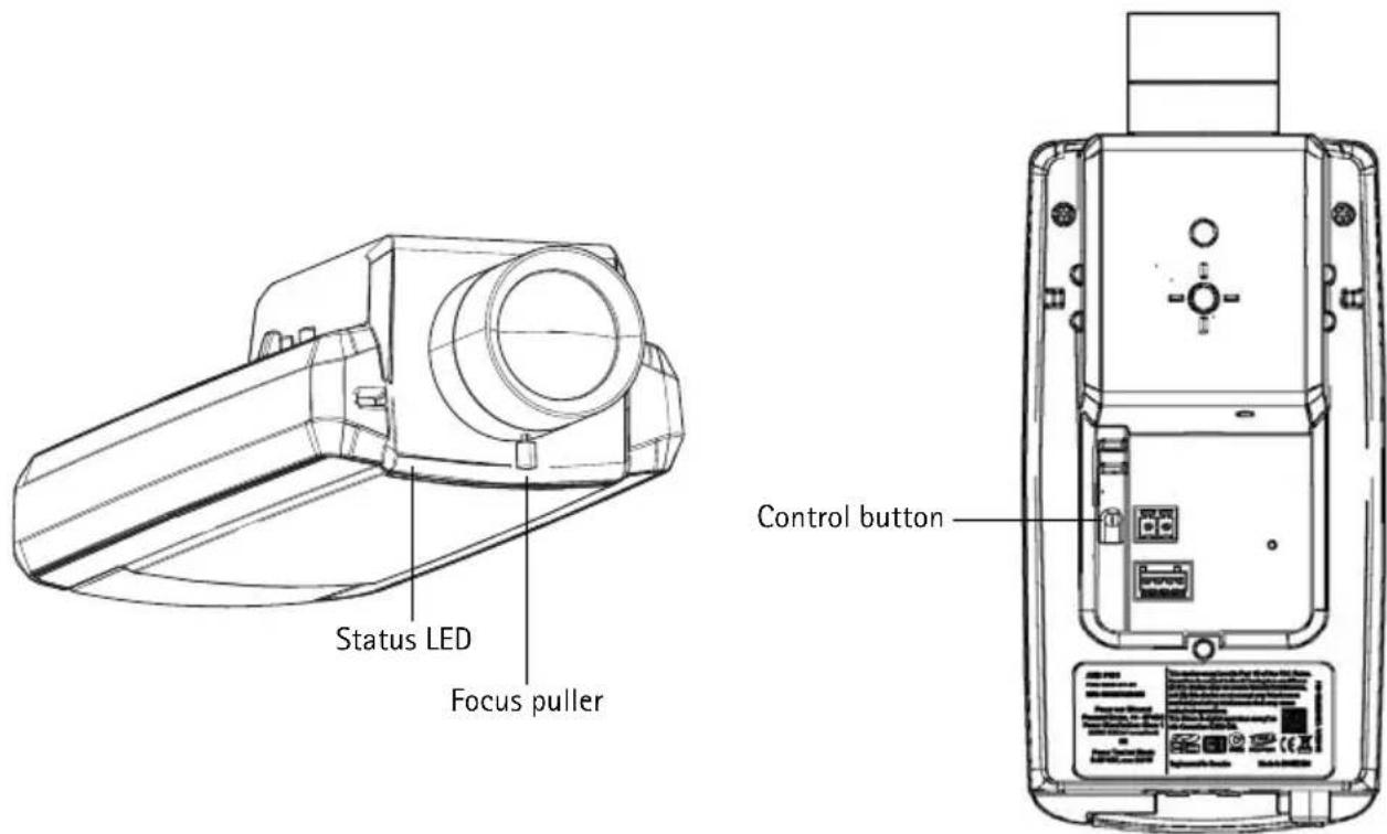
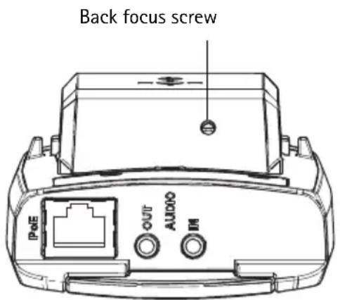
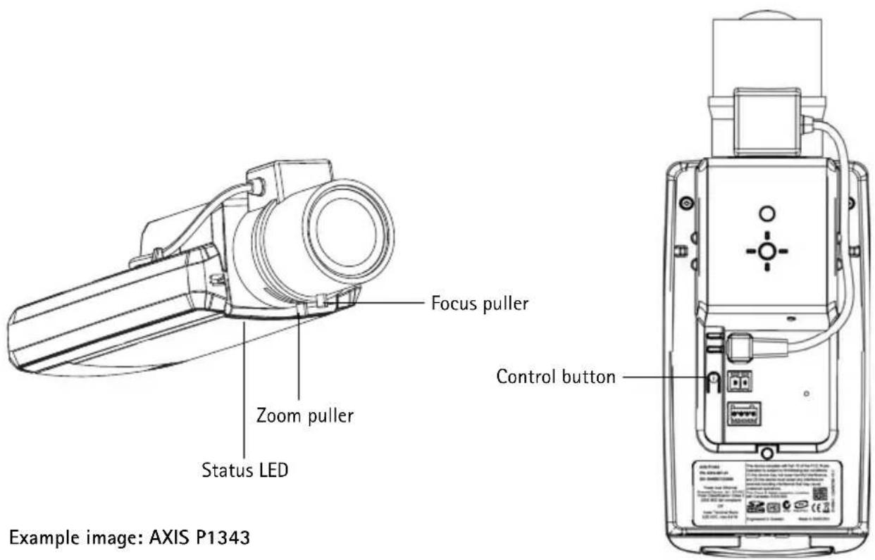
② Hardware overview
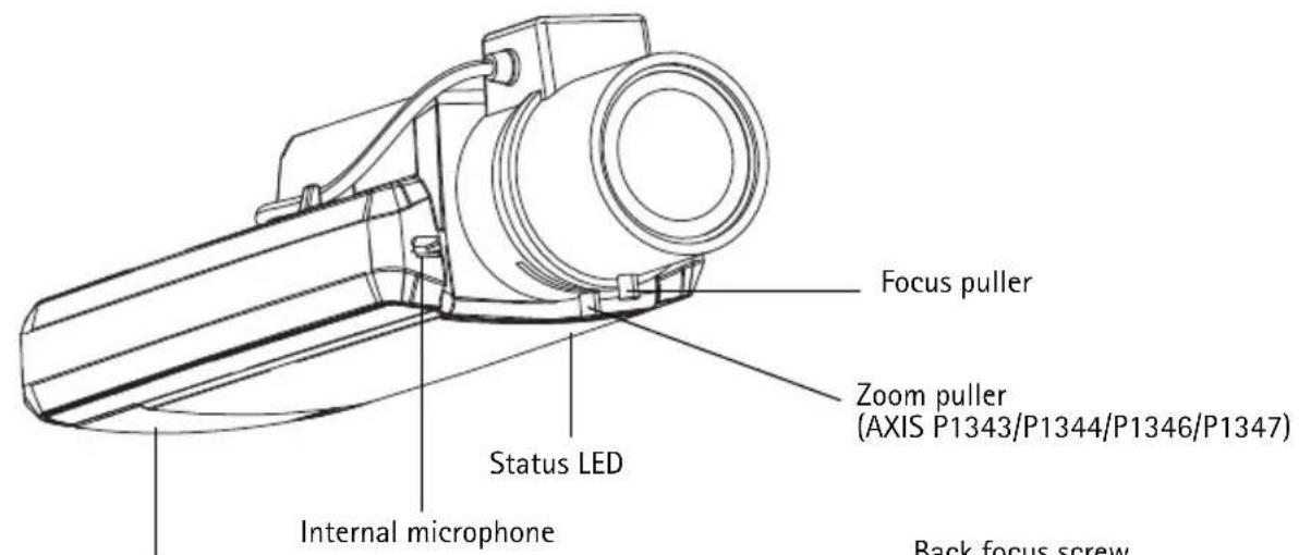
SD memory card slot
Back focus screw (AXIS P1311)
Top view - AXIS P1343
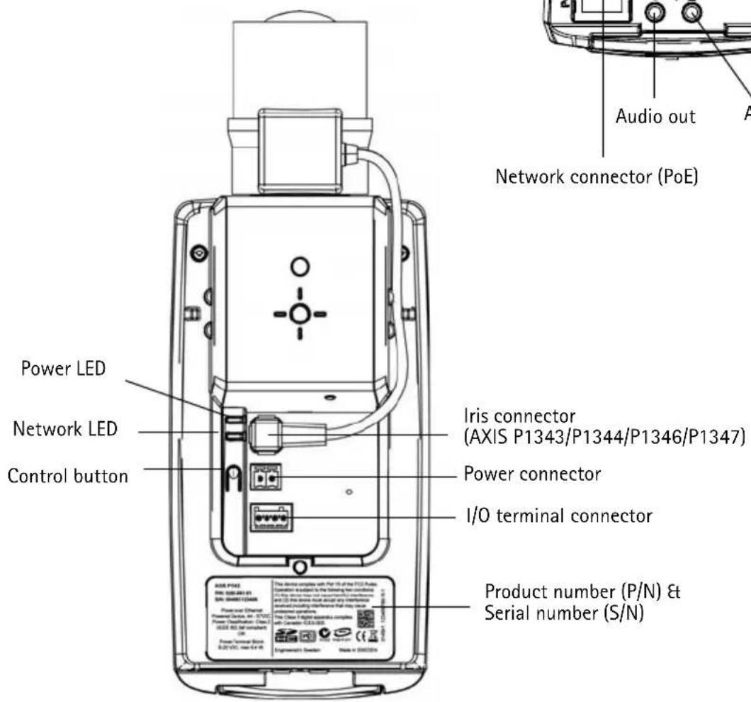
Rear view
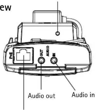
Network connector (PoE)
Dimensions
| Model H x W x D Weight | ||
| AXIS P1311 46 x | 78 x 176 mm (1.8" x 3.1" x 6.9") 584 g (1.29 lb) | |
| AXIS P1343 46 x | 78 x 192 mm (1.8" x 3.1" x 7.6") 585 g (1.29 lb) | |
| AXIS P1344 46 x | 78 x 205 mm (1.8" x 3.1" x 8.1") 620 g (1.37 lb) | |
| AXIS P1346 46 x | 78 x 198 mm (1.8" x 3.1" x 7.8") 630 g (1.39 lb) | |
| AXIS P1347 46 x | 78 x 206 mm (1.8" x 3.1" x 8.1") 680 g (1.5 lb) | |
③ Install the hardware
IMPORTANT! - AXIS P1311/P1343/P1344/P1346/P1347 is designed for indoor and outdoor use. To use the camera outdoors, it must be installed in an approved outdoor housing. Please see www.axis.com for more information on outdoor housings.
Connect the cables
- Connect external input/output devices if required, such as alarm devices. See page 19 for information on the terminal connector pins.
- Connect an active speaker and/or external microphone if required.
- Connect the camera to the network using a shielded network cable.
-
Connect power, using one of the methods listed below:
-
PoE (Power over Ethernet). PoE is automatically detected when the network cable is connected.
-
Connect an external power adapter to the power connector block; see Unit connectors, on page 18 for wiring information.
-
Check that the indicator LEDs indicate the correct conditions. See the table on page 20 for more details. Note that the Status LED can be configured to be unlit during normal operation.
4 Assign an IP address
Most networks today have a DHCP server that automatically assigns IP addresses to connected devices. If your network does not have a DHCP server the network camera will use 192.168.0.90 as the default IP address.
AXIS IP Utility and AXIS Camera Management are recommended methods for setting an IP address in Windows. These free applications are available on the AXIS Network Video Product CD supplied with this product, or they can be downloaded from www.axis.com/techsup. Depending on the number of cameras you wish to install, use the method that suits you best.
| Method Recommended for Operating system | |||
 | AXIS IP UtilitySee page 7 | Single cameraSmall installations | Windows |
 | AXIS Camera ManagementSee page 8 | Multiple camerasLarge installationsInstallation on a different subnet | Windows 2000Windows XP ProWindows 2003 ServerWindows VistaWindows 7 |
Notes:
- If assigning the IP address fails, check that there is no firewall blocking the operation.
- For other methods of assigning or discovering the IP address, e.g. in other operating systems, see page 16.
AXIS IP Utility - single camera/small installation
AXIS IP Utility automatically discovers and displays Axis devices on your network. The application can also be used to manually assign a static IP address.
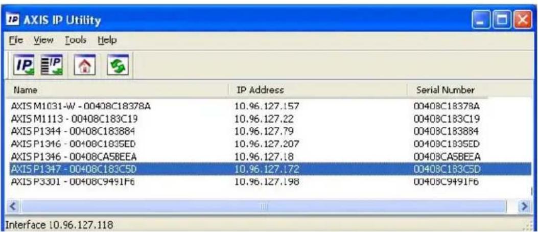
Note that the computer running AXIS IP Utility must be on the same network segment (physical subnet) as the network camera.
Automatic discovery
- Check that the network camera is connected to the network and that power has been applied.
- Start AXIS IP Utility.
- When the network camera appears in the window, double-click to open its home page.
- See page 9 for instructions on how to assign the password.
Set the IP address manually (optional)
- Acquire an unused IP address on the same network segment as your computer.
- Select the network camera in the list.
- Click the button IP Assign new IP address to selected device and enter the IP address.
- Click the Assign button and proceed according to instructions.
- Click the Home Page button to access the camera's web pages.
- See page 9 for instructions on how to set the password.
AXIS Camera Management - multiple cameras/large installations
AXIS Camera Management can automatically discover multiple Axis devices, show connection status, manage firmware upgrades and set IP addresses.
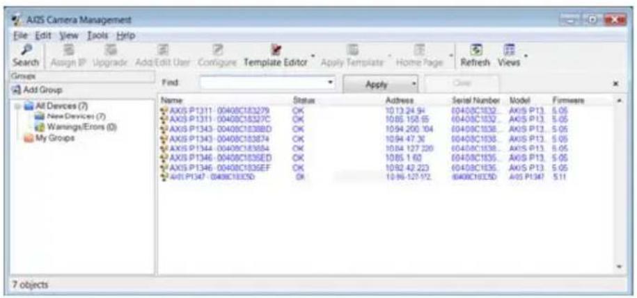
Automatic discovery
- Check that the camera is connected to the network and that power has been applied.
- Start AXIS Camera Management. When the network camera appears in the window, right-click the link and select Live View Home Page.
- See page 9 for instructions on how to set the password.
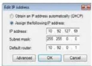
Assign an IP address in a single device
- Select the network camera in AXIS Camera Management and click the Assign IP button .IP
- Select Assign the following IP address and enter the IP address, the subnet mask and default router for the device.
- Click OK.
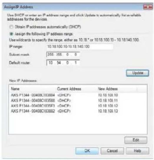
Assign IP addresses in multiple devices
AXIS Camera Management speeds up the process of assigning IP addresses to multiple devices, by suggesting IP addresses from a specified range.
- Select the devices you wish to configure (different models can be selected) and click the Assign IP button.
- Select Assign the following IP address range and enter the range of IP addresses, the subnet mask and default router the devices will use.
- Click Update. Suggested IP addresses are listed under New IP Addresses and can be edited by selecting a device and clicking the Edit button.
- Click OK.
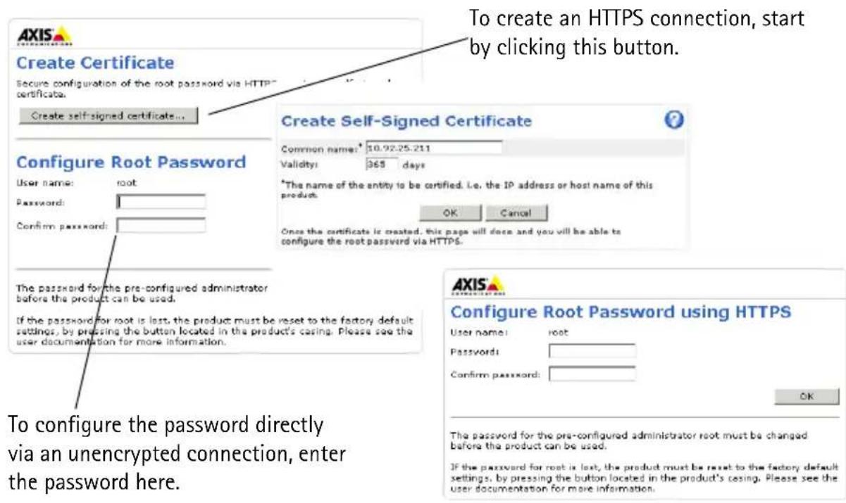
5 Set the password
To gain access to the product, the password for the default administrator user root must be set. This is done in the 'Configure Root Password' dialog, which is displayed when the network camera is accessed for the first time.
To prevent network eavesdropping when setting the root password, this can be done via an encrypted HTTPS connection, which requires an HTTPS certificate.
Note:
HTTPS (Hypertext Transfer Protocol over SSL) is a protocol used to encrypt the traffic between web browsers and servers. The HTTPS certificate controls the encrypted exchange of information.
To set the password via a standard HTTP connection, enter it directly in the first dialog shown below.
To set the password via an encrypted HTTPS connection, follow these steps:
- Click the Create self-signed certificate button.
- Provide the requested information and click OK. The certificate is created and the password can now be set securely. All traffic to and from the network camera is encrypted from this point on.
- Enter a password and then re-enter it to confirm the spelling. Click OK. The password has now been configured.
- To log in, enter the user name "root" in the dialog as requested.
Note: The default administrator user name root cannot be deleted.
- Enter the password as set above, and click OK. If the password is lost, the camera must be reset to the factory default settings. See page 20.
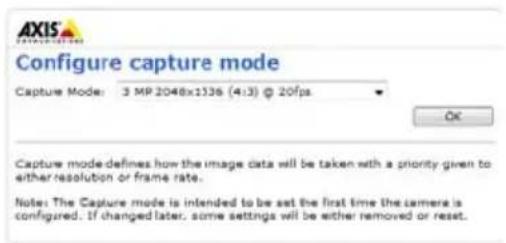
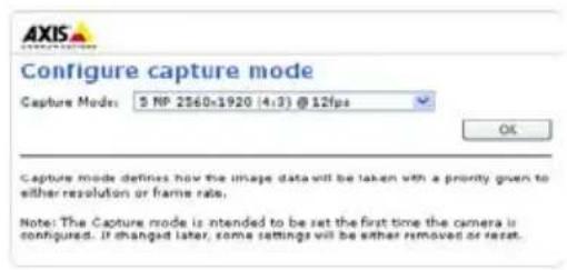
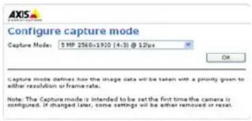
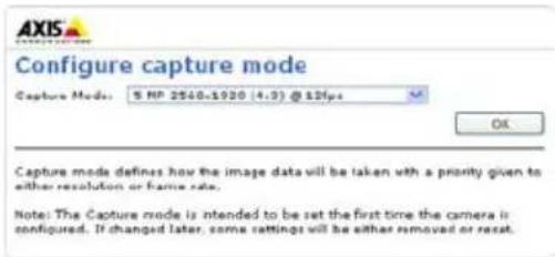
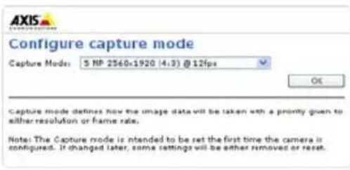
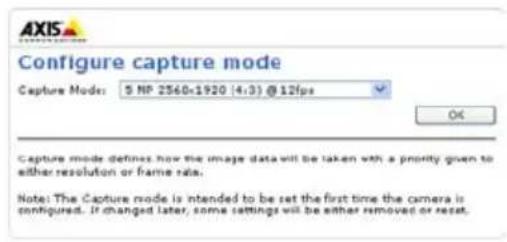
- AXIS P1346/AXIS P1347: The capture mode must be set the first time AXIS P1346 is accessed. Select the desired capture mode from the drop-down list and click OK.
Note: The capture mode can be changed later from the product's web pages, but this will reset most other settings. For more information, see the online help or User's Manual.
- If required, click Yes to install AMC (AXIS Media Control), which allows viewing of the video stream in Internet Explorer. You will need administrator rights on the computer to do this.
Note: To install AMC in Windows Vista, you must run Internet Explorer as administrator. Right-click the Internet Explorer icon and select Run as administrator.
AXIS P1346
AXIS P1347
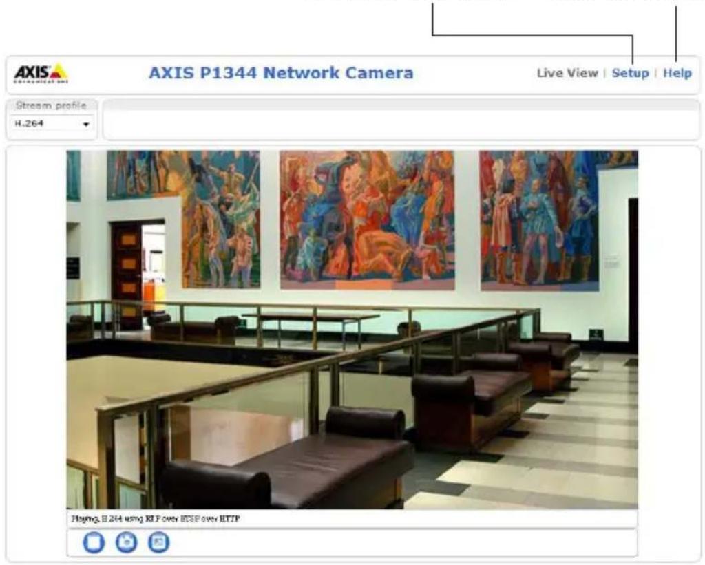
- The Live View page of the network camera is displayed; the Setup link leads to menus that allow you to customize the camera.
Setup – Provides all the tools for configuring the camera to requirements.
Help – Displays online help on all aspects of using the camera.
6 Adjust focus (AXIS P1311)
To focus AXIS P1311 follow these instructions:
- Open the product's home page in a web browser.
- Loosen the focus puller and turn the lens gently to focus the camera. Check the quality of the image in the Live View window.
- Retighten the focus puller.
Note: If the camera is mounted so that one cannot look at the image and turn the lens at the same time, use the Focus Assistant instead. See below.
Focus Assistant (AXIS P1311)
To focus AXIS P1311 using the Focus Assistant follow the instructions below:
- Mount or place the camera so that it cannot be moved.
- Power the camera and wait for about a minute.
- Set the camera to its extreme distant-focus position by loosening the focus puller and turning the lens fully clockwise.
-
Press and quickly release the Control button. When the Status LED flashes green, the Focus Assistant is enabled.
If the Status LED flashes either red or amber before you are able to adjust the lens, skip to step 7 to exit the Focus Assistant and repeat steps 3 - 7. See the notes below. -
Gently turn the lens anti-clockwise until it stops. Do not force the lens too far or it will separate from the camera.
-
Finally, turn the lens slowly clockwise until the status indicator flashes green (not red or amber).
- To exit the Focus Assistant, press the Control button again.
Note: The Focus Assistant is switched off automatically after 15 minutes.
- Retighten the focus puller.
- Open the Live View page in the web browser and check the quality of the image.
Notes:
- The view in front of the camera should not be changed during focus adjustment (steps 5 and 6). If the camera is moved, or if a finger or other object is placed in front of the lens, steps 3 - 7 will have to be repeated.
• If movements in front of the camera cannot be avoided, the Focus Assistant should not be used. - If the Control button is not released within two seconds, AXIS Dynamic DNS Service is enabled instead of the Focus Assistant.
- If the camera is mounted so that the Control button cannot be accessed, you can still use the Focus Assistant. Follow the instructions above but mount the camera after step 4 (pressing the Control button) instead and skip step 7.
Adjusting the back focus (AXIS P1311)
The back focus of AXIS P1311 might need to be adjusted when attaching a new lens that has specifications that are different from the original lens.
Turn the back focus screw clockwise to move the sensor away from the lens by 0.5 mm/r. Do not force the screw beyond the end stop since it can damage the camera.
Adjust zoom and focus (AXIS P1343/P1344/P1346/P1347)
To adjust the zoom and focus follow these instructions:
- Open the product's home page and go to Setup > Basic Setup > Focus.
- Under the Basic tab, click Open iris. If the button is inactive, the iris is already open.
- If focus has been set before, click Reset to reset the back focus.
- Loosen the zoom and focus pullers on the lens by turning them anti-clockwise. Move the pullers to set zoom and focus and check the quality of the image in the image window.
Note: If the camera is mounted so that one cannot look at the image and move the pullers at the same time, use the Focus Assistant instead. See page 13.
-
Retighten the zoom and focus pullers.
-
On the Focus page, click Fine-tune focus automatically and wait until the automatic fine-tuning is completed.
- Click Enable iris. If the button is inactive, the iris has already been enabled.
- If needed, make further adjustments under the Advanced tab. See the online help or User's Manual for more information.
Notes:
- Set focus as precisely as possible with the focus puller or Focus Assistant before starting the automatic fine-tuning. Using the focus puller normally gives the best result.
- The iris should always be opened to its maximum while focusing; this gives the smallest depth of field and thus the best conditions for correct focusing.
Focus Assistant (AXIS P1343/P1344/P1346/P1347)
To focus AXIS P1343/P1344/P1346/P1347 using the Focus Assistant, follow the instructions in steps 1 - 3 on page 12 before you start with the steps below.
- Mount or place the camera so that it cannot be moved.
- Loosen the zoom puller by turning it anti-clockwise. Move the puller to set the zoom level. Retighten the zoom puller.
- Set the camera to its extreme distant-focus position by loosening the focus puller and turning the lens fully clockwise.
-
Press and quickly release the Control button. When the Status LED flashes green, the Focus Assistant is enabled. If the Status LED flashes either red or amber before you are able to adjust the lens, skip to step 7 to exit the Focus Assistant and repeat steps 3 - 7. See the notes below.
-
Gently turn the lens anti-clockwise until it stops.
- Finally, turn the lens slowly clockwise until the status indicator flashes green or amber (not red).
- To exit the Focus Assistant, press the Control button again.
Note: The Focus Assistant is switched off automatically after 15 minutes.
-
Retighten the focus puller.
-
Open the Live View page in the web browser and check the quality of the image.
-
Continue with steps 6 - 8 on page 12.
Notes:
- The view in front of the camera should not be changed during focus adjustment (steps 5 and 6). If the camera is moved, or if a finger or other object is placed in front of the lens, steps 3 - 7 will have to be repeated.
- If movements in front of the camera cannot be avoided, the Focus Assistant should not be used.
- If the Control button is not released within two seconds, AXIS Dynamic DNS Service is enabled instead of the Focus Assistant.
- If the camera is mounted so that the Control button cannot be accessed, you can still use the Focus Assistant. Follow the instructions above but mount the camera after step 4 (pressing the Control button) instead and skip step 7.
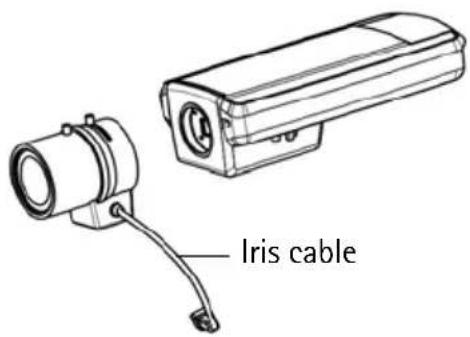
Replacing the lens
Note: This section applies to the AXIS P1347 Network Camera; and to the AXIS P1346 Network Camera when the firmware supports it.
There are optional lenses available for your network camera. To replace the camera's lens:
- Disconnect the iris cable.
- Unscrew the existing lens; attach and screw on the new lens.
Note: There is no need to restart the camera if one P-Iris lens is replacing another. The camera must however be restarted if you are interchanging between a P-iris, DC-Iris or fixed/manual iris lens.
In order to set the focus and position the lens, the camera must be connected to the network. For instructions, please refer to the Installation Guide supplied with the camera.
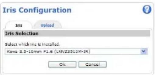
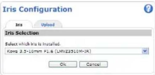
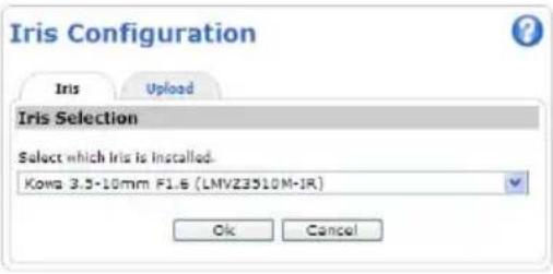
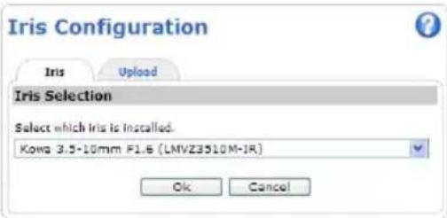
Select the iris configuration
- Go to Video & Audio > Camera Settings from the Setup link in the camera's web page.
- Click Edit... against Iris configuration:. In the Iris Configuration dialog that appears, choose the iris that corresponds to the camera's lens from the drop-down list and click Ok.
Note: For P-Iris lenses not listed in the drop-down list, download the iris configuration file from www.axis.com. To do this click the Upload tab, browse to the file and click Upload. After the file has been uploaded, select the iris configuration corresponding to the lens from the drop-down list and press Ok.
In case you select a DC iris configuration for a P-iris lens, an error message will appear against Iris configuration: in the Camera Settings page.
Exposure Settings within the Camera Settings page
![Exposure Settings Exposure value: 50 [0..100] Exposure controls: Automatic Enable Backlight compensation: Exposure zones: Auto Defined [center] Edit... IR cut filters: Auto Exposure priority: Default Iris configuration: Kova 3.5-10mm F1.6 (LMVZ3510M-IR) Edit... Enable automatic iris adjustment Iris adjustment: 50 [0..100] F 2.31](/content/2026/06/1255356/images/2d3eacda63f1cbe34dc238899e6b400f0dcc0f94cc2a4a37fbb08741bc0051fe.jpg)
Other methods of setting the IP address
The table below shows the other methods available for setting or discovering the IP address. All methods are enabled by default, and all can be disabled.
| Use in operating system | Notes | |
| AVHS Service Connection | All To connect the camera to an AVHS server, refer to the server provider's Installation guide. For information and help to find a local AVHS Service Provider go to www.axis.com/hosting | |
| UPnPTM | Windows When enabled on your computer, the camera is automatically detected and added to My Network Places/Network. | |
| Bonjour | MAC OSX (10.4 or later) | Applicable to browsers with support for Bonjour. Navigate to the Bonjour bookmark in your browser (e.g. Safari) and click on the link to access the camera's web pages. |
| AXIS Dynamic DNS Service | All A free service from Axis that allows you to quickly and simply install your camera. Requires an Internet connection with no HTTP proxy. See www.axiscam.net for more information. | |
| ARP/Ping | All See below. The command must be issued within 2 minutes of connecting power to the camera. | |
| DHCP server | All To view the admin pages for the network DHCP server, see the server's own documentation. | |
Set the IP address with ARP/Ping
- Acquire a free static IP address on the same network segment your computer is connected to.
- Locate the serial number (S/N) on the camera's label.
- Open a command prompt on your computer and enter the following commands:
| Windows syntax |
| arp -s <IP Address> <Serial Number> ping -l 408 -t <IP Address> |
| Windows example |
| arp -s 192.168.0.125 00-40-8c-18-10-00 ping -l 408 -t 192.168.0.125 |
| UNIX/Linux/Mac syntax |
| arp -s <IP Address> <Serial Number> temp ping -s 408 <IP Address> |
| UNIX/Linux/Mac example |
| arp -s 192.168.0.125 00:40:8c:18:10:00 temp ping -s 408 192.168.0.125 |
- Check that the network cable is connected to the camera and then start/restart the camera, by disconnecting and reconnecting power.
- Close the command prompt when you see 'Reply from 192.168.0.125:...' or similar.
- In your browser, type in http://
in the Location/Address field and press Enter on your keyboard.
Notes:
• To open a command prompt in Windows: from the Start menu, select Run... and type cmd. Click OK.
- To use the ARP command in Windows Vista, right-click the command prompt icon and select Run as administrator.
• To use the ARP command on a Mac OS X, use the Terminal utility in Application > Utilities.
Unit connectors
Network connector - RJ-45 Ethernet connector. Supports Power over Ethernet. Using shielded cables is recommended.
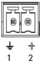
Power connector - 2-pin connector block used for power input.
| Function | Pin number | Description | |
| GND 1 Ground | |||
| DC Power 2 Power input 8-20 | V DC AXIS P1311: max 2.8 W | AXIS P1343: max 6.4 WAXIS P1344: max 6.4 WAXIS P1346: max 9.6 WAXIS P1347: max 9.0 W | |
Audio in - 3.5 mm input for a mono microphone, or a line-in mono signal (left channel is used from a stereo signal).
Audio out – Audio output (line level) that can be connected to a public address (PA) system or an active speaker with a built-in amplifier. A pair of headphones can also be attached. A stereo connector must be used for the audio out.
SDHC memory card slot - A standard or high capacity SD memory card can be used for local recording with removable storage.
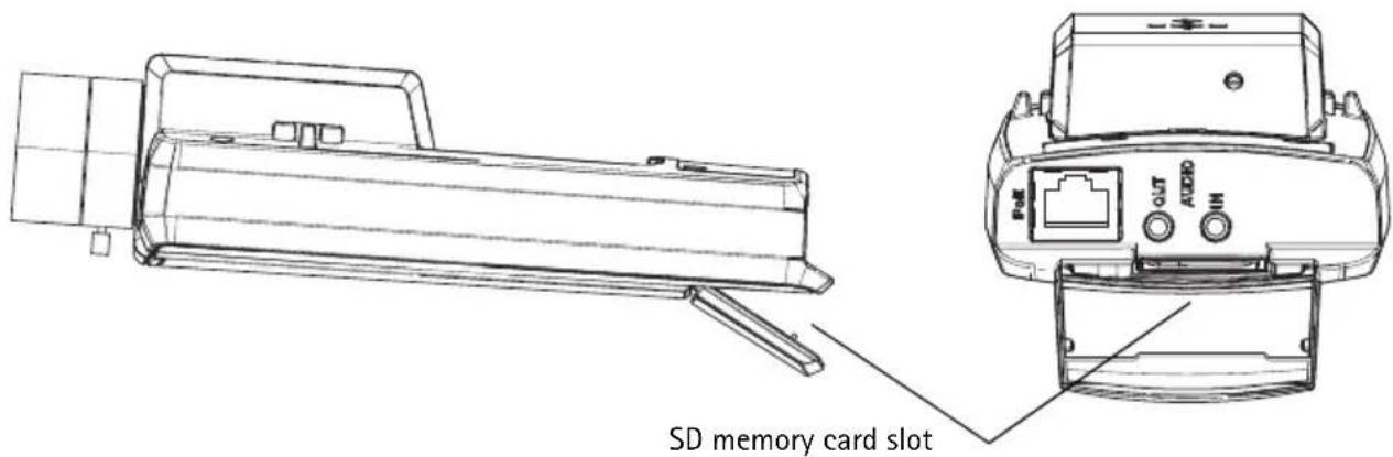
To insert an SD card, lift the SD card cover on the rear of the network camera, and carefully insert the SD card into its slot.
To remove an SD card lift the cover and gently push the card in and release it. The SD card will back out of the slot where it can then be removed.
I/O terminal connector – Used in applications for e.g. motion detection, event triggering, time lapse recording and alarm notifications. In addition to an auxiliary power and a GND pin, it provides the interface to:
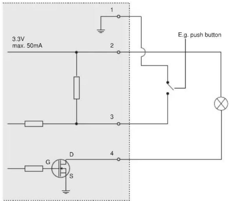
- 1 digital output – For connecting external devices such as relays and LEDs. Connected devices can be activated by the VAPIX® Application Programming Interface (API), by the output buttons on the Live View page or by an Event Type. The output will show as active (shown under Events > Port Status) if the
- 1 digital input – An alarm input for connecting devices that can toggle between an open and closed circuit, for example: PIRs, door/window contacts, glass break detectors, etc. When a signal is received the state changes and the input becomes active (shown under Events > Port Status).
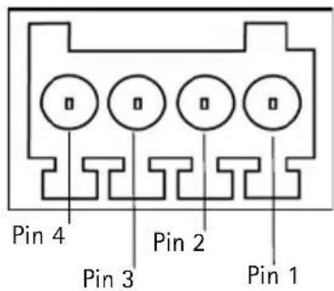
| Function | Pin | Notes Specifications | |
| GND 1 Ground | |||
| 3.3 V DC Power | 2 Can be used to power auxiliary equipment.Note: This pin can only be used as power out. | Max load = 50 mA | |
| Digital Input | 3 Connect to GND to activate, or leave floating (unconnected) to deactivate. | Min. input = -40 V DCMax. input= +40 V DC | |
| Digital Output | 4 Uses an open-drain NFET transistor with the source connected to GND. If used with an external relay, a diode must be connected in parallel with the load, for protection against voltage transients. | Max. load =100 mAMax. voltage = +40 V DC | |
The following connection diagram gives an example of how to connect an auxiliary device to the network camera.
LED indicators
| LED Color Indication | ||
| Network | Green | Steady for connection to a 100 Mbit/s network. Flashes for network activity. |
| Amber | Steady for connection to 10 Mbit/s network. Flashes for network activity. | |
| Unlit No network connection. | ||
| Status Green Steady green for normal operation.Note: The Status LED can be configured to be unlit during normal operation, or to flash only when the camera is accessed. To configure, go to Setup > System Options > LED settings. See the online help files for more information. | ||
Status LED when using the Focus Assistant
| Status LED Color Indication | |
| Green Step 4: Focus Assistant is enabledStep 6: The lens is optimally adjusted | |
| Amber Step 4: The camera has been moved, or an object has been inserted in front of the lens. Exit and restart the Focus Assistant.Step 6: The lens is less optimally adjusted | |
| Red Step 4: The camera has been moved, or an object has been inserted in front of the lens. Exit and restart the Focus Assistant.Step 6: The lens is poorly adjusted | |
Resetting to the factory default settings
This will reset all parameters, including the IP address and (AXIS P1343/P1344/P1346/P1347 only) focus position, to the factory default settings:
- Disconnect power from the camera.
- Press and hold the Control button and reconnect power.
- Keep the Control button pressed until the Status indicator displays amber (this may take up to 15 seconds).
-
Release the Control button. When the Status indicator displays green (which can take up to 1 minute) the process is complete and the network camera has been reset.
-
Re-assign the IP address, using one of the methods described in this document.
-
AXIS P1343/P1344/P1346/P1347: Refocus the camera, using one of the methods described in this document.
It is also possible to reset parameters to the original factory default settings via the web interface. For more information, please see the online help or the User's Manual.
Accessing the camera from the Internet
Once installed, your network camera is accessible on your local network (LAN). To access the camera from the Internet, network routers must be configured to allow incoming traffic, which is usually done on a specific port
- HTTP port (default port 80) for viewing and configuration
- RTSP port (default port 554) for viewing H.264 video streams
Please refer to the documentation for your router for further instructions. For more information on this and other topics, visit the Axis Support Web at www.axis.com/techsup
Further information
The User's Manual is available from the Axis Web site at www.axis.com or from the Axis Network Video Product CD supplied with this product.
Tip!
Visit www.axis.com/techsup to check if there is updated firmware available for your network camera. To see the currently installed firmware version, see Camera Settings > About in the camera's web page.
AXIS P1347
Exposure Settings within the Camera Settings page
![Exposure Settings Exposure value: 50 [0..100] Exposure controls: Automatic Enable Backlight compensation: Exposure zones: Auto Defined [center] Edit... IR cut filters: Auto Exposure priority: Default Iris configuration: Kow 3.5-10mm F1.6 (LMVZ3510M-IR) Edit... Enable automatic iris adjustment Iris adjustment: 50 [0..100] F 2.31](/content/2026/06/1255356/images/97d25076e52fa53d71abb2da9b31bee3f7ac27a3f527becbb5bbbb8cc912206b.jpg)
AXIS P1347
Exposure Settings within the Camera Settings page
![Exposure Settings Exposure value: 50 [0..100] Exposure control: Automatic Enable Backlight compensation: Exposure zones: Auto Defined [center] Edit... IR cut filter: Auto Exposure priority: Default Iris configuration: Kowa 3.5-10mm F1.6 (LMVZ3510M-IR) Edit... Enable automatic iris adjustment Iris adjustment: 50 [0..100] F 2.31](/content/2026/06/1255356/images/e5993bc3e8dae0c8e4a493212c0ca18cb2fb0d929be5e78dba07fa2b7e7e11a4.jpg)

AXIS P1347
Focus Assistant (AXIS P1311)
Exposure Settings within the Camera Settings page
![Exposure Settings Exposure value: 50 [0..100] Exposure controls: Automatic Enable Backlight compensation: Exposure zones: Auto Defined [center] Edit... IR cut filters: Auto Exposure priority: Default Iris configuration: Kowa 3.5-10mm F1.6 (LMVZ3510M-IR) Edit... Enable automatic iris adjustment Iris adjustment: 50 [0..100] F 2.31](/content/2026/06/1255356/images/f75af631029db35b9c57124a1572c67b86bc81d8e10427d1c6701decb804d853.jpg)
AXIS P1347
Exposure Settings within the Camera Settings page
![Exposure Settings Exposure value: 50 [0..100] Exposure control: Automatic Enable Backlight compensation: Exposure zones: Auto Defined [center] Edit... IR cut filter: Auto Exposure priority: Default Iris configuration: Kowa 3.5-10mm F1.6 (LMVZ3510M-IR) Edit... Enable automatic iris adjustment Iris adjustment: 50 [0..100] F 2.31](/content/2026/06/1255356/images/188500e8727c7eff2753aed680a539e1d2cfd0671c09c22aad6e37ad6463c4b5.jpg)
Safety Notice - Battery Replacement
The AXIS P1311/P1343/P1344/P1346/P1347 uses a 3.0V CR2032 Lithium battery as the power supply for its internal real-time clock (RTC). Under normal conditions this battery will last for a minimum of 5 years. Low battery power affects the operation of the RTC, causing it to reset at every power-up. A log message will appear when the battery needs replacing. The battery should not be replaced unless required! If the battery does need replacing, please contact www.axis.com/techsup for assistance.
- Danger of Explosion if battery is incorrectly replaced
- Replace only with the same or equivalent battery, as recommended by the manufacturer
- Dispose of used batteries according to the manufacturer's instructions
©2009-2010 Axis Communications AB
Ver. 3.0
Printed: June 2010
Part No. 38731
- About this Document
- Legal Considerations
- Electromagnetic Compatibility (EMC)
- Equipment Modifications
- Liability
- RoHS
- WEEE Directive
- Support
- AXIS P13 Network Camera Series - Installation Guide
- Installation steps
- Dimensions
- ③ Install the hardware
- Connect the cables
- Assign an IP address
- Notes:
- AXIS IP Utility - single camera/small installation
- Automatic discovery
- Set the IP address manually (optional)
- AXIS Camera Management - multiple cameras/large installations
- Assign an IP address in a single device
- Assign IP addresses in multiple devices
- Set the password
- Note:
- Adjust focus (AXIS P1311)
- Focus Assistant (AXIS P1311)
- Adjusting the back focus (AXIS P1311)
- Adjust zoom and focus (AXIS P1343/P1344/P1346/P1347)
- Focus Assistant (AXIS P1343/P1344/P1346/P1347)
- Replacing the lens
- Select the iris configuration
- Other methods of setting the IP address
- Set the IP address with ARP/Ping
- Unit connectors
- Resetting to the factory default settings
- Accessing the camera from the Internet
- Further information
- Tip!
- AXIS P1347
- Safety Notice - Battery Replacement
Brand : AXIS
Model : P1347
Category : Surveillance Camera