
9400 - Printer Océ - Free user manual and instructions
Find the device manual for free 9400 Océ in PDF.


| Product Type | Large Format Printer |
| Brand | Océ |
| Model | 9400 |
| Dimensions (W x D x H) | 1200 mm x 600 mm x 800 mm |
| Weight | 100 kg (220 lb) |
| Power Supply | 220-240 V, 50/60 Hz |
| Power Consumption | 150 W (standby), 600 W (printing) |
| Print Technology | LED array or inkjet |
| Resolution | Up to 2400 x 1200 dpi |
| Media Size | Up to 36 inches wide |
| Connectivity | Ethernet, USB 2.0, Wi-Fi optional |
| Display | Color touchscreen |
| Print Speed | Up to 10 A1 pages per minute |
| Main Functions | Print, copy (optional), scan (optional) |
| Maintenance & Cleaning | Regular printhead cleaning and alignment; replace maintenance cartridges |
| Safety Features | Automatic shutdown, overheat protection, grounded plug |
| Repairability | Modular design; replaceable printheads, rollers, and fuser |
| Spare Parts Availability | Common consumables available from authorized dealers |
| Operating Temperature | 15°C to 30°C (59°F to 86°F) |
| Humidity Range | 20% to 80% RH (non-condensing) |
| User Manual Included | Yes, digital PDF available |
| Warranty | 1 year standard (extendable) |
Frequently Asked Questions - 9400 Océ
User questions about 9400 Océ
0 question about this device. Answer the ones you know or ask your own.
Ask a new question about this device
Download the instructions for your Printer in PDF format for free! Find your manual 9400 - Océ and take your electronic device back in hand. On this page are published all the documents necessary for the use of your device. 9400 by Océ.
USER MANUAL 9400 Océ
This manual contains a description regarding the Océ 9400 system and a detailed explanation about the plot functions. The introduction (chapter 1) contains a general description of the working methods for using the copier and it is recommended that you read at least this chapter.
Overview of copier parts on the covers
To assist you in finding parts of the copier/printer and the functions on the operating panel quickly, an illustration of the Océ 9400 is presented on the inside front cover and of the operating panel on the inside back cover, both of which can be folded out.
Safety information
This manual contains the following safety information:
- Appendix B lists ‘Instructions for safe use’. You are advised to read this information before you start to actually use the copier. Technical safety information such as safety data sheets can also be found in appendix B.
■ Where applicable, cautions and warnings are used throughout this manual to draw your attention to safety precautions to be taken.
Trademarks
PostScript is a trademark of Adobe Systems Inc.
■ HP-GL, HP-GL/2, HP-RTL and DESIGNJET are trademarks of Hewlett Packard Company. Microsoft, MS, and MS-DOS are registered trademarks of Microsoft Corporation.
MS-Windows is a trademark of Microsoft Corporation.
CalComp is a trademark of California Computer Products Inc.
TIFF is a trademark of Aldus Corporation.
CALS is a military standard.
Copyright
Océ-Technologies B.V. Venlo, The Netherlands © 1999
All rights reserved. No part of this work may be reproduced, copied, adapted, or transmitted in any form or by any means without written permission from Océ.
Océ-Technologies B.V. makes no representation or warranties with respect to the contents hereof and specifically disclaims any implied warranties of merchantability or fitness for any particular purpose.
Further, Océ-Technologies B.V. reserves the right to revise this publication and to make changes from time to time in the content hereof without obligation to notify any person of such revision or changes.
Contents
Chapter 1
Getting started
The Océ 9400 printer 10
The printer operating panel 11
Buttons 12
Display 12
The Océ 9400 copier 14
The scanner operating panel 15
Stand-by mode 16
Buttons and functions 16
Switching on/off the copier 18
Switching on/off the printer 19
Chapter 2
Installation of the printer
Connect the printer to your host environment 22
Centronics 23
Serial 24
Handshake protocol 24
Baud rates 25
Bits combination 25
Serial parity and stop bits 26
Port type 27
Turnaround delay 27
Inter character delay 28
SCSI 29
Setup the memory configuration 31
Input buffer 31
Bitmap buffer 32
Chapter 3
(Re)load media and toner
Inserting a new print material roll 36
Automatic roll switching 36
Reloading rolls 37
Cutting the paper to get a straight leading edge 40
Printing using the manual feed 44
Programming media settings 45
Refilling toner 48
Chapter 4
Copy jobs
Introduction 52
Making copies 53
Starting the copy process 53
Activating/de-activating the rewind function 54
Change settings 56
Number of copies 56
Copying using roll 1 or roll 2 56
Copying using manual feed 57
Reduction/enlargement 58
Copying using synchro or standard cut 58
Adjusting the leading/trailing edge 60
Modifying the exposure 63
Inverted copies/Blueprints 63
Poster mode 64
Chapter 5
Print jobs
Printing files 66
Océ applications 67
Océ drivers 67
Cut method 67
Plot Center 68
Leading/trailing edge 68
Demo plot 69
Cancel plot 70
Chapter 6
Upload jobs
Introduction 72
Chapter 7
Customizing the printer
Defining pen settings 76
Defining language settings 79
Automatic language sensing 79
Data format recognition 80
Manual data format selection 81
Océ languages (VDF/BGL) 82
Océ print origin 82
Océ step size 83
Océ pen priority 84
HP-GL 85
HP-GL print origin 85
HP-GL page advance 85
Merge mode 86
HP-GL/2 87
HP-GL/2 print origin 87
HP-GL/2 page advance 87
HP-GL/2 pen priority 88
Designjet compatibility 89
Merge mode 89
HP-RTL 90
CalComp 91
CalComp print origin 91
Checksum parameter 91
CalComp pen priority 92
Merge mode 92
End of Message parameter 93
Synchronization code parameter 94
Double synchronization code parameter 94
CalComp step size 96
Raster formats 97
CALS 97
NIRS 97
TIFF 97
C4 (EDMICS) 97
PostScript level 2 98
PostScript data format selection 98
Manual data format selection 98
PostScript page layout 99
Default PostScript page size 99
Chapter 8
Advanced printer menu functions
End of plot time out 102
Selecting the media saver 103
Nesting 103
Autoposition 106
Media saver time out 107
Flush media saver 107
Media saver plot size 108
Replot 109
Setting the number of copies 110
Poster mode 111
Dump configuration 112
Transformation 113
Print rotation 113
Print scaling 113
Autoscaling 114
Display 117
Service 118
Chapter 9
Solving problems
Problem solving printer 120
Printer warnings 120
Operator recoverable errors (printer) 121
Clearing paper jams 122
Printer recoverable errors 124
Problem solving copier 125
Scanner error 125
Operator recoverable errors scanner 126
Please wait 126
Printer error 126
Clearing original jam 126
Cleaning the glass platen 127
Appendix A
Overview and tables
Product specifications printer 130
Product specifications scanner 131
Interfaces 132
Centronics protocol 132
Serial protocols 132
SCSI protocol 133
Ethernet protocol 133
Centronics port configuration 134
Serial port configuration 136
SCSI port configuration 137
Originals that can be used 139
Copy material that can be used 140
Overview of standard zoom formats 142
Order of standard sizes for using standard cut 143
Appendix B
Safety information
Instructions for safe use 146
Safety data sheets 147
Safety data sheet Océ 9400 printer 148
Safety data sheet Océ 9400 scanner 149
Safety data sheet Océ 9400 toner 150
Safety data sheet Océ 9400 developer 152
Safety data sheet Océ 9400 OPC drum 154
EPA ENERGY STAR ^® 156
Appendix C
Miscellaneous
Notation conventions 160
Reader's comment sheet 161
Addresses of local Océ organisations 163
Index 165
Chapter 1 Getting started
This chapter contains a general description of the Océ 9400 and how to install and setup the printer to be ready for use. Furthermore it describes how to get the copier ready to copy.

The Océ 9400 printer
The Océ 9400 is a wide format printing system. The machine is equipped with an automatic 1- or 2-roll dispenser. The Océ 9400 prints on paper, transparent paper, vellum and polyester film. Its powerful digital technology offers users optimal ease of use and the reliability that one might expect from Océ.
The Compact Output Stacker is the newest option of the Océ 9400. This output stacker offers a smart and efficient disposition of printed or copied drawings.
The machine has features, such as:
■ automatic language sensing and remote control
- multiple interfaces
■ fast, high quality printing
■ autoscale of vector data
■ media saver
Optional:
■ automatic 2-roll dispenser
■ memory extension modules
- compact output stacker
■ PostScript level 2
- Ethernet interface
■ high capacity delivery tray
The printer operating panel
The operating panel which is located at the right hand side of the printer console is easy to use (see figure 1). The panel consists of buttons and a display consisting of 2 lines of 16 characters each.

[1] Printer operating panel
In normal operation, the printer can process print jobs, and the 2 line display indicates the current status of the printer (e.g. ‘READY’ or ‘RASTERIZING’).
With the buttons on the operating panel you may enter the Program mode and easily setup the printer according to your requirements.
Buttons
Program Program To activate the program mode and to enter the top level menu. In this mode the user can use next/select previous ▶ buttons to step through the menu.
Pressing Program on if there is no action during 1 minute in Program mode, the machine returns to the status mode.
Note: If you press the Program button while the printer is printing, the led above the program button flashes. As soon as the printing process is ready, you automatically enter the program mode. Bear in mind that when you are in the Program mode, the printer will not print.
Next/select (next/select) To select an option or a setting in the menu. Or in case a submenu is present, enter a menu on a lower level.
Previous (previous) By pressing this button you go one level higher in the menu.
Browse buttons ◄r ▶ These two buttons are used to select another mode at the same level of the menu, or to display the next or previous option from the option list.
Cancel/continue cancel/continue This button is used to cancel the present print job or to continue after an operator recoverable error.
Display
The two-lines LCD display provides feedback about print job status in normal mode and menu items in Program mode.
During normal operation the following messages may appear:
Status messages indicates the actual status of the printer, e.g. READY, PROCESSING etc.
Warning messages during a warning message the printer will continue to operate, but it is possible that the print quality is not optimal, e.g. REFILL TONER.
Error messages the printer will stop and the user has to take action. For example: PAPER JAM.
Action messages an action message prompts the user to perform an action before the print job is resumed. For example: ‘FEED SHEET’ in case of manual feed.
The Océ 9400 copier
The Océ 9400 is also a copier for large documents (e.g. architectural or engineering drawings). The machine is easy to use and makes copies on paper, transparent paper, vellum and polyester film with the quality and reliability that one might expect from Océ.
To use the Océ 9400 as a copier, a wide-format scanner is connected to the printer. Please note that you still can send print jobs when the Océ 9400 is used as a copier. The print jobs are processed after copying is finished.
The machine detects whether a user wants to print a document or to make a copy, and switches automatically after 1 minute to printing mode.
The scanner operating panel
The operating panel which is located at the right hand side of the scanner is easy to use (see figure 2).

[2] Scanner operating panel
Stand-by mode
The operating panel (see the illustration on inside back cover) on the Océ 9400 is easy to use and specially designed to carry out copy jobs.
After switching on the scanner, (see page 18), the machine is always ready for operation. In this state, the operating panel is in stand-by mode, which is in fact a low power mode. The operating panel activates in the following situations:
■ when you feed an original
■ when a button on the operating panel is pressed
Note: If you do not work with the operating panel for more than 1 minute and no original is fed, it returns automatically to stand-by mode. The Océ 9400, however, remains always ready for operation. If however the original remains in the scanner feed table, the operating panel returns to stand-by mode after 2.5 minutes but the settings will remain.
Buttons and functions
Start button The copy process starts with the current settings. After pressing the start button no more changes are possible for the copies that are already being processed, with exception of the ‘stop/correction’ button.
-/+ button Press these buttons to increase or decrease the number of copies. The copy quantity can be changed at all times. Adjustable from 1 to 19 copies.
Stop/Correction button This button has two functions: stopping the original during the original transport, or correcting the selected settings.
■ Before starting the copying process :
Pressing this button once: The number of copies selected is erased and the default value '1' will be displayed. All other settings remain unchanged. Pressing this button twice: All settings that have been selected will also be erased and reset to the default settings. The number of copies selected will revert to '1', if it is not already set to this value. If required, you can select new settings.
■ During the copying process:
If you press this button while an original is being fed, the copying process will stop immediately. If you want to abort a multicopy job after the scanning of the original is finished, you must abort the copying process by pressing the 'cancel/continue' button on the printer. You have to open the top cover of the scanner to remove the original ('Clearing original jam' on page 126).
Media button With this button you choose the input of the copy material.
Possible input selections are roll 1, roll 2 or manual feed.
Exposure scale You modify the exposure level with the ‘lighter’ and ‘darker’ buttons. The exposure level can be changed at all times.
Auto exposure button With this button the Automatic Background
Compensation can be switched on or off.
Cut button This button toggles between synchro cut mode and standard cut mode.
In synchro cut mode, the copy is cut at the length of the original.
In standard cut mode, the copy is cut at a standard length.
Edge button This button toggles between leading and trailing edge. With this button you add or remove a strip at the leading or trailing edge.
Zoom button You can vary the zoom factor between 25% and 400%. Either in fixed steps or percentages.
Up/Down buttons When using zoom-, edge- or the standard cut-mode you can modify the values of these modes by pressing the up or down button.
Start indication This indication above the start button is on if the scanner is ready to make a scan and is off when the scanner is scanning an original. Also this is the only indication which is on when the scanner is in standby mode.
Please wait This indication is blinking when the user has pressed the start button but the system is not ready to scan. E.g. because the system is busy with a multicopy job or because the system is processing a printjob.
Printer error This indication is on if there is an error on the printer. Check the operating panel of the printer for the error message.
Switching on/off the copier
Switching on the copier consists of:
■ switching on the scanner
■ switching on the printer (see page 19).
After switching on the system is ready for operation. In this state, the machine is in stand-by mode. There is no need to switch it off after each copy job. You can leave the copier switched on for the rest of the day. At all times, the Océ 9400 is ready for operation.
If the copier has been inactive for more than 1 minute, the operating panel returns automatically to the stand-by mode. The operating panel of the scanner is activated in the following situations:
- you feed an original
■ a button on the operating panel is pressed
Switching on the scanner
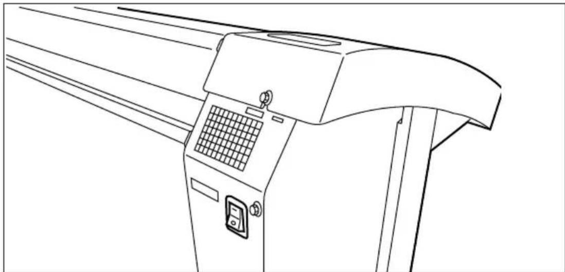
1 Set the on/off switch at the rear of the scanner, to position '1' (see figure 3). If the mains is connected correctly, the green switch will light up.
natural_image
Line drawing of a mechanical device with control panel and buttons (no text or symbols)[3] On/off switch of the scanner
Note: The system is immediately ready for use. The scanner can be switched on and off independently from the printer and without any particular order.
Switching off the scanner
1 Set the on/off switch at the rear of the scanner, to position '0' (see figure 3).
Switching on/off the printer
After switching on the printer is ready for operation.
Switching on the printer
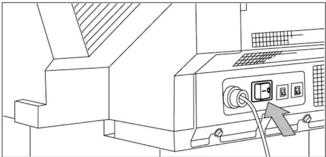
1 Set the on/off switch at the rear of the printer to position '1' (see figure 4). If the mains is connected correctly, the green switch will light up.
natural_image
Line drawing of a computer monitor with an attached control panel and cable (no text or symbols)[4] On/off switch of the printer
Note: The printer is ready for use after approx. 15 seconds.
Switching off the printer
2 Set the on/off switch at the rear of the printer to position '0' (see figure 4).
Attention: Switching off the printer during a print job may cause loss of information or a paper jam.
Chapter 2 Installation of the printer
This chapter describes how to connect your printer to your host environment and how to configure the printer to your convenience.

Connect the printer to your host environment
The Océ 9400 supports several types of interfaces (Serial, Centronics, TCP/IP, Novell Netware, NETBIOS, Ethertalk).
To ensure proper operation, please follow the next steps when connecting your host to the Océ 9400.
1 Ensure both, the host and the Océ 9400 are switched OFF (see ‘Centronics’ on page 23).
2 Connect the appropriate interface cable to your local host and the corresponding interface connector to the Océ 9400 (see ‘Centronics’ on page 23) or (see ‘Serial’ on page 24).
3 Switch on the Océ 9400 (see ‘Centronics’ on page 23).
4 Enter the Program mode to configure the connection parameters (see 'Centronics' on page 23) or (see 'Serial' on page 24).
5 Enter the Program mode to configure the Océ 9400 to your requirements (see 'Printing files' on page 66) or (see 'Customizing the printer' on page 75).
6 Leave Program mode, the printer is ready for use. If applicable install and configure the appropriate host software on your local host environment.
Centronics
Connection through the Centronics interface is straightforward and data transfer is fast. You have to set one parameter, the transmission speed. You can select ‘normal’ or ‘fast’. Default is ‘normal’.

Connecting Centronics
1 Switch off the printer and host.
2 Connect one end of the Centronics cable to the computer's Centronics parallel port.
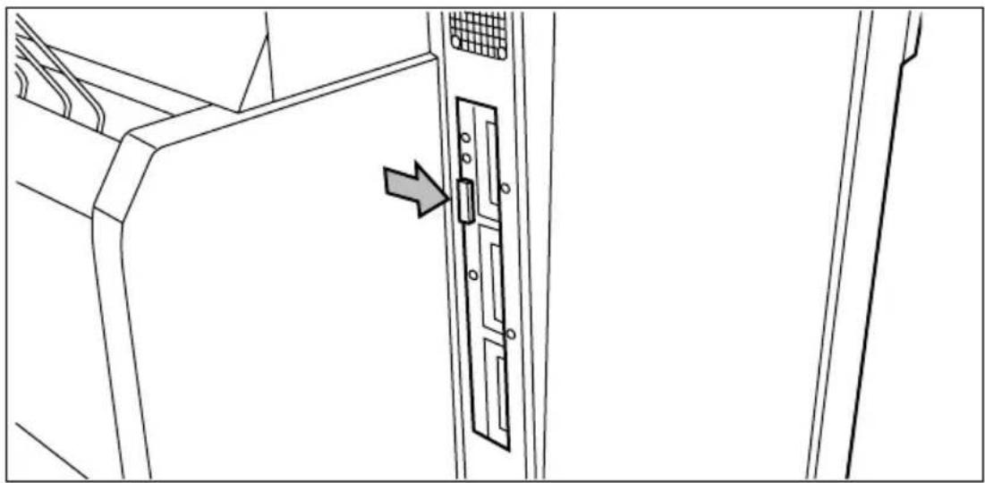
3 Connect the other end to the printer's Centronics parallel port (see figure 5).
natural_image
Technical line drawing of a door panel with an arrow pointing to the door handle (no text or symbols present)[5] Centronics port
4 Switch on the printer.

Defining transmission speed
1 Press Prograder the main menu.
2 Select the CONFIGURATION menu using the or button.
3 Press next/netectic CONFIGURATION menu.
4 Select the CONNECTIONS menu using the or button.
5 Press next to the connection menu.
6 Select the CENTRONICS item using the or button.
7 Press next to the CENTRONICS menu.
8 Select the required speed using the ◄ or button.
9 Press next/sell in the selected speed.
10 Press (reobrane the main menu.
Serial
If you are using the serial port you need to configure a list of paramaters. In the following procedures all parameters are described.
Connecting serial
1 Switch off the printer and host
2 Connect one end of the serial cable to the computer's serial port.
3 Connect the other end to the printer's Serial port (see figure 6).

natural_image
Line drawing of a door panel with an arrow pointing to the door handle (no text or symbols)[6] Serial port
4 Switch on the printer.
Handshake protocol
You can select CTS2 or XON4 or BOTH. The default setting is BOTH. This means that the printer will automatically respond to either XON/XOFF (software protocol) or CTS (hardware protocol).
Defining handshake protocol
1 Press Progrator the main menu.
2 Select the CONFIGURATION item using the or button.
3 Press (next/selecthe) CONFIGURATION menu.
4 Select the CONNECTIONS item using the ◀ or button.
5 Press (next/ selecting) CONNECTIONS menu.
6 Select the SERIAL item using the or button.
7 Press next to select the SERIAL menu.
8 Select the PROTOCOL item using the ◀ or button.
9 Press next/selecthe PROTOCOL menu.
10 Select the XON_XOFF item using the or button.
11 Press (next/see the) XON_XOFF menu.
12 Select the appropriate setup using the ◀ or button.
13 Press next/selectm the selected setup.
14 Press (p)ogave the main menu.
Baud rates
The following baud rate are allowed: 300, 600, 1200, 2400, 4800, 9600, 19200 and 38400. Default is 9600.
▼ Defining the baud rate
1 Press Recogner the main menu.
2 Select the CONFIGURATION item using the or button.
3 Press next to select the CONFIGURATION menu.
4 Select the CONNECTIONS item using the or button.
5 Press (next to select the) CONNECTIONS menu.
6 Select the SERIAL item using the ◄ or button.
7 Press (next/betech) SERIAL menu.
8 Select the TRANSMISSION item using the ◄ or button.
9 Press (next/selecthe) TRANSMISSION menu.
10 Select the BAUD RATE item using the ◄ or button.
11 Press next to the BAUD RATE menu.
12 Setup the required baud rate using the ◄r button.
13 Press next/selectm the selected baud rate.
Note: Choose the fastest baud rate compatible with your system.
14 Press (p)o-grare the main menu.
Bits combination
When transmitting data via the serial interface, 8 or 7 bits per byte are used.
Default is 8.
▼ Defining the bits combination
1 Press Recogner the main menu.
2 Select the CONFIGURATION item using the or button.
3 Press (next/see the) CONFIGURATION menu.
4 Select the CONNECTIONS item using the ◄ or button.
5 Press (next/selecthe) CONNECTIONS menu.
6 Select the SERIAL item using the or button.
7 Press (next/selecthe) SERIAL menu.
8 Select the TRANSMISSION item using the or button.
9 Press (next/selecthe) TRANSMISSION menu
10 Select the BAUD RATE item using the or button.
11 Press (next/selecthe) BAUD RATE menu.
12 Select the number of bits per byte using the or button.
13 Press next/selectm the selected number of bits.
14 Press (pogave the main menu.
Serial parity and stop bits
For correct data transfer, the parity and stop bits (framing) are required. You can select the following combinations:
■ None, 1 stop No parity, 1 stop bit
■ None, 2 stop No parity, 2 stop bits
■ Even, 1 stop Even parity, 1 stop bit
■ Even, 2 stop Even parity, 2 stop bits
- Odd, 1 stop Odd parity, 1 stop bit
■ Odd, 2 stop Odd parity, 2 stop bits
Default is NONE, 1 STOP
Setting the parity and stop bits
1 Press Recogner the main menu.
2 Select the CONFIGURATION item using the ◀ or button.
3 Press (next/ selecting) CONFIGURATION menu.
4 Select the CONNECTIONS item using the ◄ or button.
5 Press (next selecthe) CONNECTIONS menu.
6 Select the SERIAL item using the ◀ or button.
7 Press next to select the SERIAL menu.
8 Select the TRANSMISSION item using the ◄ or button.
9 Press (next/ selecting) TRANSMISSION menu.
10 Select the FRAMING item using the ◀ or button.
11 Press (next/selecthe) FRAMING menu.
12 Select the appropriate parity and number of stop bits using the or button.
13 Press next/second the selected parity and number of stop bits.
14 Press Poolgrave the main menu.
Port type
In order to give the maximum connection flexibility, the printer's serial port can be set to either DTE (data terminal equipment) or DCE (data communications equipment). Default is DTE.
▼ Selecting the port type
1 Press Prograr the main menu.
2 Select the CONFIGURATION item using the ◄ or button.
3 Press next to the CONFIGURATION menu.
4 Select the CONNECTIONS item using the or button.
5 Press (next/selectc) CONNECTIONS menu.
6 Select the SERIAL item using the or button.
7 Press (next/search) SERIAL menu.
8 Select the PROTOCOL item using the ◀r button.
9 Press (next select) PROTOCOL menu.
10 Select the PORT item using the ◄ or button.
11 Press (next/search) PORT menu.
12 Select the appropriate port using the ◀ or button.
13 Press next/selectm the selected port.
14 Press (prograve the main menu.
Note: The serial interface on the printer conforms to the RS-232-C and RS-423-C standards. If your computer uses the RS-423-C serial interface, the port type must be DTE.
Turnaround delay
The printer offers possible delays from 0 to 10 seconds, with increments of 0.01 second. Default is 1.0.
Setting the turnaround delay
1 Press (Prognar the main menu.
2 Select the CONFIGURATION item using the or button.
3 Press (next/research) CONFIGURATION menu.
4 Select the CONNECTIONS item using the or button.
5 Press (next/selecthe) CONNECTIONS menu.
6 Select the SERIAL item using the or button.
7 Press (next/selecthe) SERIAL menu.
8 Select the PROTOCOL item using the or button.
9 Press next/selecthe PROTOCOL menu.
10 Select the DELAY item using the or button.
11 Press next to the DELAY menu.
12 Select the TURNAROUND item using the or button
13 Press (next/ selecting) TURNAROUND menu.
14 Select the required delay using the ◄ or button.
15 Press next/selectm the selected delay.
16 Press (pograwe the main menu.
Inter character delay
The printer offers possible delays from 0 to 10 seconds, with increments of 0.01 second. Default is 1.0.
Setting the inter character delay
1 Press Programm the main menu.
2 Select the CONFIGURATION item using the or button.
3 Press (next/selecthe) CONFIGURATION menu.
4 Select the CONNECTIONS item using the ◄ or button.
5 Press (next to select the) CONNECTIONS menu.
6 Select the SERIAL item using the ◀r button.
7 Press next to select the SERIAL menu.
8 Select the PROTOCOL item using the ◀ or button.
9 Press (next/ selecting) PROTOCOL menu.
10 Select the DELAY item using the ◀ or button.
11 Press (next/see the) DELAY menu.
12 Select the INTER CHAR item using the ◀ or button.
13 Press (next/selecthe) INTER CHAR menu.
14 Select the required delay using the ◄ or button.
15 Press next/selectm the selected delay.
16 Press (Poolgrave the main menu.
SCSI
If you are using the SCSI port (for the scan to file option), you need to configure one parameter; the SCSI ID. You can select a number between 0 and 7. The default is 0. Check the configuration of your computer to find an ID which is not used by another device on the SCSI-bus to which you want to connect the Océ 9400.
Note: The SCSI port is used only for the scan to file option to upload data from the controller to the connected PC.
There is also a switch on the Océ 9400 SCSI board near the SCSI-connector which should be configured. This switch configures the termination on the SCSI-bus and should be set to “on” if the Océ 9400 is the last device on the SCSI-bus chain. It should be set to “off” when it is placed ‘between’ other devices on the SCSI-bus.
Connecting SCSI
1 Switch off the printer and the host.
2 Connect one end of the SCSI cable to the computer's SCSI port.
3 Connect the other end to the printer's SCSI port (see figure 7).

natural_image
Line drawing of a door panel with a directional arrow pointing to the door (no text or symbols)[7] SCSI port
4 Switch on the printer and the host.
Defining the SCSI ID
1 Press Prograder the main menu.
2 Select the CONFIGURATION menu using the ◀ or button.
3 Press next/ selecting CONFIGURATION menu.
4 Select the CONNECTIONS menu using the or button.
5 Press (next/see the) CONNECTION menu.
6 Select the EXT X SCSI item using the or button. EXT X means that the SCSI board is inserted in slot X of the Océ 9400 controller (X can be 1, 2 or 3).
7 Press next to the EXT X SCSI menu.
8 Select the required ID (ranging from 0 to 7) using the ◄ or button.
9 Press next/selectm the selected ID.
10 Press (Roograme the main menu.
11 Switch the printer off/on to activate the configured SCSI-ID.
Setup the memory configuration
Depending on the complexity of print jobs, the printer's memory partitions can be configured.
Input buffer
This option enables you to set the print spool input buffer size. You can select small or large. A small buffer allows more free memory for processing a larger number of vectors. A large buffer allows the host to be freed sooner. Default is 'small'.
Files in the input buffer will be processed and printed in the same order as they arrive.
Setting the input buffer size
1 Press Recogner the main menu.
2 Select the CONFIGURATION item using the or button.
3 Press next to select the CONFIGURATION menu.
4 Select the BUFFERS item using the or button.
5 Press (next/selecthe) BUFFERS menu.
6 Select the INPUT BUFFER item using the or button.
7 Press next/selecthe INPUT BUFFER menu
8 Select the required input buffer size using the ◀ or button.
9 Press next/selectm the selected size.
10 Press Programs the main menu.
▼ Activating the new input buffer size
1 Switch the printer off and then on again.
Note: If you do not restart the printer the new memory allocation is not taken into account. Any print data in the printer's memory (files in the queue), will be lost when you switch off the printer.
Bitmap buffer
This buffer defines a percentage of the total RAM memory that can be used as the bitmap partition. This value will be set between two values depending on the RAM configuration.
The installed RAM can be divided into:
- bitmap partition
■ processing area for vector files
The size of the bitmap partition determines the max. dimensions of the image to be printed (e.g. 18 Mb = A0).
The size of the vector processing area determines the ability to process complex files (e.g. larger number of vectors).
A high percentage of bitmap partition allocation, allows printing of long plots without windowing.
A low percentage of bitmap partition allocation, means the ability of processing very complex files (vector and raster).
Setting the bitmap buffer
1 Press Program the main menu.
2 Select the CONFIGURATION item using the ◄ or button.
3 Press next to the CONFIGURATION menu.
4 Select the BUFFERS item using the ◄ or button.
5 Press next to select the BUFFER menu.
6 Select the BITMAP BUFFER item using the ◄ or button.
7 Press (next to select the) BITMAP BUFFER menu
8 Select the required bitmap partition using the ◀ or button
9 Press next/second the required partition.
10 Press program the main menu.

Activating the new bitmap buffer size
1 Switch the printer off and then on again.
Note: If you do not restart the printer the new memory allocation is not taken into account. Any print data in the printer's memory will be lost when you switch off the printer.
| RAM | Min Max |
| 32 | 58 % 82 % |
| 48 | 39 % 88 % |
| 64 | 29 % 90 % |
Chapter 3 (Re)load media and toner
This chapter describes how to insert new media, how to add toner and how to program the media settings.

Inserting a new print material roll
Before you use the copier for the first time, you have to choose the order in which the paper formats are shown on the scanner operating panel. You can do this by choosing between ISO, ANSI or ARCHITECT paper format on the printer operating panel.
Setting the media format
1 Press Regulator the main menu.
2 Select the CONFIGURATION item using the or button.
3 Press next to the CONFIGURATION menu.
4 Select PLOT MANAGER using the ◄ or button.
5 Press next-selecthe PLOT MANAGER menu.
6 Select MEDIA FORMAT using the or button.
7 Press next/selecthe MEDIA FORMAT menu.
8 Select the required format using the ◀ or button.
9 Press next/second the selected format.
10 Press Programme the main menu.
If the message ‘ROLL EMPTY’ appears in the display, you have to load a new roll of print material. Depending on your configuration you can reload roll 1 and/or roll 2.
Note: After reloading the plot is re-printed automatically.
Automatic roll switching
If a roll becomes empty the printer reports a roll empty error. The printing stops. The printer clears the paperpath and generates a message to indicate that the printer is ready to accept a new print command. If the correct material type and material format is on the other roll, the printer will use the other roll and will resume printing automatically.
If there is no match of material type and material format, you have to refill the empty roll.
Defining automatic roll switching
1 Press Regulator the main menu.
1 Select the MEDIA SETTINGS item using the or button.
2 Press next-selecthe MEDIA SETTINGS menu.
3 Select MEDIA MODE using the or button.
4 Press next/selecthe MEDIA MODE menu.
5 Select AUTO SWITCH using the or button.
6 Press (text/selecthe) AUTO SWITCH menu.
7 Select the required setting On ot OFF using the ◀ or button.
8 Press next/second the selected setting.
9 Press Programs the main menu
Reloading rolls
Reloading roll 1
1 Open the drawer completely (see figure 8).

natural_image
Technical line drawing of a mechanical device with spring and roller components (no text or symbols)[8] Opening the drawer Remove the roll holder from the drawer (see figure 9)
2 Remove all scraps of material from the paperfeed mechanism!

natural_image
Technical line drawing of a mechanical device with no visible text or symbols[9] Removing the roll holder from the drawer
3 Remove the empty core from the roll holder while pressing the knob (see figure 10).
4 Slide the roll holder in the new roll of material while pressing the knob (see figure 10).
It is important to have the knob at the right hand side and paper as shown in figure 10.
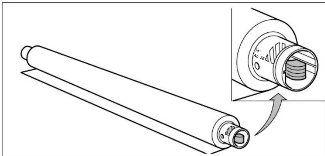
[10] Pressing the knob
5 Align the roll with the appropriate lines on the roll holder while pressing the knob. This line has to be completely visible.
6 Place the roll holder with the material in the drawer (see figure 11).

natural_image
Technical line drawing of a mechanical assembly with a zoomed-in section showing a circular component and a curved arrow (no text or symbols)[11] Repositioning the roll
7 Feed the material between the input guide plates against the rollers.
8 Turn the rollers until the material is visible (see figure 12). Also refer to the sticker inside the drawer.

natural_image
Technical line drawing of a mechanical assembly with rotating components and guide rails (no text or symbols)[12] Feeding the material
9 If you have inserted a roll with another material or with a different width, you have to program the correct width and material type (refer to 'Programming media settings' on page 45).
If you want to cut the paper to get a straight leading edge refer to ‘Cutting the paper to get a straight leading edge’ on page 40.
Otherwise continue with the next step.
10 Close the drawer.
11 Press the button 'Cancel/Continue'.
Cutting the paper to get a straight leading edge
If the paper does not have a straight leading edge, you can cut it off at right angles from the roll.
▼ Cutting the paper from roll 1 or roll 2
1 Open the drawer.
2 Feed the paper manually until it is approximately 5 cm above the top drawer.
3 Close the paper drawer.
4 Press Programmer the main menu.
5 Select the MEDIA SETTINGS item using the or button.
6 Press next to the Media SETTINGS menu.
7 Select CUT MEDIA using the or button.
8 Press next/sellebe paper.
9 Open the paper drawer.
10 Remove the scrap of material.
11 Pull back the material until it is visible and positioned correctly (see figure 12 on page 39).
12 Close the drawer.
13 Press the button 'Cancel/Continue'.
Reloading roll 2
1 Open the cover to get access to roll 2 (see figure 13).

natural_image
Technical line drawing of a mechanical device with internal components and directional arrows indicating motion (no text or symbols)[13] Opening the lower drawer
2 Remove the roll holder (see figure 14).
3 Remove all scraps of material from the paperfeed mechanism!

natural_image
Technical line drawing of a mechanical device with rollers and frame (no text or symbols)[14] Removing the roll holder from the lower drawer
4 Remove the empty core from the roll holder while pressing the knob (see figure 10 on page 38).
5 Slide the roll holder in the roll of print material while pressing the knob (see figure 10 on page 38).
It is important to have the knob at the right hand side and the paper as shown in figure 10.
6 Align the roll with the appropriate lines on the roll holder while pressing the knob.
7 Place the roll holder with the material in the lower paper compartment (see figure 15).

natural_image
Technical line drawing of a mechanical device with an inset showing a circular component labeled '+', no text or symbols present.[15] Repositioning the roll
8 Feed the material between the input guide plates against the rollers. Turn the rollers until the material is visible (see figure 16). Also refer to the sticker inside the drawer.

natural_image
Mechanical assembly diagram showing a shaft and housing with directional arrows indicating motion (no text or labels)[16] Feeding the material
9 If you have inserted a roll with another material or with a different width, you have to program the correct width and material type (refer to 'Programming media settings' on page 45).
If you want to cut the paper to get a straight leading edge refer to ‘Cutting the paper to get a straight leading edge’ on page 40.
Otherwise continue with the next step.
10 Close the lower paper compartment.
11 Press the button 'Cancel/Continue'.
Printing using the manual feed
There are two possibilities to select manual feed:
- via remote control commands added to the print file (by means of Plot Director, drivers (see 'Upload jobs' on page 71).
■ by changing the MEDIA MODE in the program mode.
If the user wants to use manual feed, he has to:
1 program the media settings on the printer, refer to ‘Programming media settings’ on page 45.
2 send the file.
3 wait until the message 'FEED SHEET' appears in the printer display.
4 feed the sheet of paper portrait into the printer.
5 hold the paper until the engine pulls-in the first part of the sheet.
If the user has selected manual feed in a print file, the printer will ask the user via the operating panel, to feed the sheet into the printer, at the moment this job is processed. There will be a user-selectable time-out between 30 and 300 seconds on feeding the sheet. Default timeout is 60 seconds. See ‘Setting the time-out for manual feed’ on page 47. If the user does not feed the sheet within this time the job is flushed and the next job will be processed.
Inserting print material in the manual feed
1 Feed the print material centrally into the feed table in accordance with the guidelines (see figure 17).
Note: The minimum length of the print material must be 420 mm.

natural_image
Technical line drawing of a mechanical device with directional arrows indicating movement or flow (no text or symbols present)[17] Manual feed
Programming media settings
If you have inserted a new roll with another material or with a different width, you have to program the new roll specifications. These specifications are:
■ width of the material.
You can select A0 (841 mm), A1 (594 mm), A2 (420 mm), A3 (297), E (34"), D (22"), C (17"), B (11"), E+ (36"), D+ (24"), C+ (18"), B+ (12"), 30", 500 mm, 700 mm and B1 (707 mm). Default is 36".
- kind of media (refer to (see ‘Overview of copy material’ on page 141).
■ auto roll selection:
By activating this function the machine automatically selects the correct roll, depending on original size.
- auto roll switch:
If you activate this function the machine automatically switches to the other roll, if the used one becomes empty. The switch only occurs if the kind of media and the width of the material is the same for both rolls.
Materials Weight Media type setting
| Plain paper 75 g/m | ^2 | paper |
| Plain paper 110 g/m | ^2 | paper |
| ECO papers 75 g/m | ^2 | paper |
| Translucent paper 60 g/m | ^2 | translucent |
| Transparent paper 80/85 g/m | ^2 | transp <= 95 gr |
| 90/95 g/m^2 | transp <= 95 gr | |
| 110/115 g/m^2 | transp 110 gr | |
| Polyester film 3.5 mil | film <= 4 mil | |
| PPC film 3.5 mil | film <= 4 mil | |
| PPC Type C Polyester film 3.5 mil | film <= 4 mil | |
| Clear polyester film 4 mil | film <= 4 mil | |
| Contrast film | 3.5 mil | film <= 4 mil |
| Polyester film ** | 4.5 mil | film 4.5 mil |
| Vellum | 20 lbs | vellum |
| Vellum | 16 lbs | vellum |
| Contrast paper 135 g/m | ^2 | paper |
| Fluor paper | 90 g/m^2 | paper |
| Pastel paper 80 g/m | ^2 | paper |
** The sticker on this polyester roll contains ‘4 mil’, but the thickness is really 4.5 mil.
Programming media width settings
1 Press Program the main menu.
2 Select the MEDIA SETTINGS item using the or button.
3 Press next selecthe MEDIA SETTINGS menu.
4 Select ROLL 1, ROLL 2, MANUAL FEED using the or button.
5 Press next selecthe ROLL or MANUAL FEED menu.
6 Select the WIDTH item using the ◄ or button.
7 Press next/selacthe WIDTH menu.
8 Select the desired width using the or button.
9 Press next selectm the selected width.
10 Press Programs the main menu.
Programming media type settings
1 Press Progrator the main menu.
2 Select the MEDIA SETTINGS item using the ◀ or button.
3 Press next/selecthe MEDIA SETTINGS menu.
4 Select ROLL 1, ROLL 2, MANUAL FEED using the or button.
5 Press Text Selecthe ROLL or MANUAL FEED menu.
6 Select the TYPE item using the ◀ or button.
7 Press next/selecthe TYPE menu.
8 Select the desired media type using the or button.
9 Press next/second the selected media type.
10 Press Programme the main menu.
Programming default paper feed
Roll 1 is default.
1 Press Program the main menu.
2 Select the MEDIA SETTINGS item using the ◀ or button.
3 Press Text Selecthe MEDIA SETTINGS menu.
4 Select MEDIA MODE using the ◀r button.
5 Press Text Selecthe MEDIA MODE menu.
6 Select the DEF. PAPER FEED using the ◄ or button.
7 Press next select the DEF. PAPER FEED menu.
8 Select the default roll using the ◀ or button.
9 Press next/selectm the selected mode.
10 Press Programme the main menu.
Programming automatic roll selection
1 Press Progrator the main menu.
2 Select the MEDIA SETTINGS item using the or button.
3 Press next to the MEDIA SETTINGS menu.


4 Select MEDIA MODE using the or button.
5 Press (textselecthe) MEDIA MODE menu.
6 Select AUTO ROLL using the or button.
7 Press next/selecthe AUTO ROLL menu.
8 Select on or off using the or button.
9 Press text selentm the selected mode.
10 Press Programs the main menu.
Programming automatic switching
1 Press Progrator the main menu.
2 Select the MEDIA SETTINGS item using the or button.
3 Press TextSelecthe MEDIA SETTINGS menu.
4 Select MEDIA MODE using the or button.
5 Press next to the MEDIA MODE menu.
6 Select AUTO SWITCH using the ◄ or button
7 Press next select the AUTO SWITCH menu.
8 Select on or off using the or button.
9 Press next selectm the selected mode.
10 Press Programm the main menu.
Setting the time-out for manual feed
Default is 60 seconds.
1 Press Progrator the main menu.
2 Select the MEDIA SETTINGS item using the ◀ or button.
3 Press (text/selacthe) MEDIA SETTINGS menu.
4 Select MANUAL FEED using the ◀ or button.
5 Press (next/selecthe) MANUAL FEED menu.
6 Select the TIMEOUT using the ◀ or button.
7 Press (text/selecthe) TIMEOUT menu.
8 Select the desired timeout using the ◀ or button.
9 Press next selentm the selected timeout.
10 Press Programme the main menu.
Refilling toner
If the message ‘REFILL TONER’ --- > Press Continue, appears in the display, you must refill toner immediately.
Refilling toner
Attention: Use only Océ B4 toner (the B4 toner is equal to the Océ 9400 toner).
1 Unscrew the knurled nut at the left hand side of the printer and open the left cover (see figure 18).

natural_image
Technical line drawing of a mechanical component with a curved arrow indicating rotation or motion (no text or symbols present)[18] Unscrewing the knurled nut and opening the cover
2 Shake the toner bottle thoroughly and open the bottle.
3 Screw in the bottle clockwise in a slanted position (see figure 19).

[19] Screwing in the bottle
4 Move the toner bottle to a vertical position (see figure 19) and 20).

[20] Adding toner
5 Tap the toner out of the bottle.
6 When the toner bottle is empty return the bottle to the original position.
7 Unscrew the toner bottle anti clockwise.
Replacing the waste toner bag
8 Pull the waste toner bag from the holder and place the cap provided on the bag (see figure 21).

natural_image
Diagram of a mechanical device with a tool interacting with a component, showing motion and assembly (no text or symbols)[21] Replacing the waste toner bag
9 Slide a new waste toner bag over the holder.
10 Close the cover and tighten the knurled nut.
11 Press the 'Continue' button to resume printing.
Chapter 4 Copy jobs
This chapter describes how to make copies.

Introduction
With the Océ 9400, you can make copies on paper, transparent paper, vellum and polyester film, while Océ's Image Logic Technology ensures optimal copy quality.
Depending on your configuration your system is equipped with a 1 roll- or 2 roll-dispenser. With the use of the ‘media’ button you can select from which roll you want to copy, or if you want to manually feed a sheet of paper.
With the Océ 9400 you can make 1:1 copies and you can reduce or enlarge your original from 25% to 400%. You can set the zoom in fixed or in % steps. The default setting is 100%.
The Océ 9400 cuts the paper to the length of the original, this is called synchro cut. Or, if you have selected standard cut mode, the copy is cut at a standard length, (see ‘Copying using synchro or standard cut’ on page 58).
The automatic exposure setting ensures the production of background-free copies from most line-drawings. If you have an extremely dark or light original, or an original with pasted parts or photographs, you may have to adjust the exposure setting manually (see ‘Modifying the exposure’ on page 63).
Making copies
The copying process starts after pressing the ‘start’ button. Before pressing the ‘start’ button, you can change the settings.

Feeding the original
1 Insert the original face down and right aligned, along the original guide on the scanner feed table in such way that the line is completely visible (see figure 22).

natural_image
Line drawing of a wall-mounted air conditioner unit with control panel (no text or symbols)[22] Inserting the original
The original will be transported about 1 centimeter to a defined position.
2 Now you are ready to change settings or to start the copy process (see ‘Starting the copy process’ on page 53).
If you make a copy within the time-out of 1 minute, the machine will use the settings of the previous copy job.
Starting the copy process
If you press the ‘start’ button without changing any settings, the settings of the previous copy job will be used or the default settings of the machine:
■ number of copies 1
■ using roll 1
- zoom 100%
■ synchro cut
■ no leading /trailing edge
■ auto exposure on; exposure setting 0.
Default settings are used in the following situations:
■ after switching on
■ after pressing stop/correct twice
■ after a time-out of 1 minute (since the end of previous copy job has expired).
If the ‘start’ button is pressed and the printer is not busy, the original will be scanned. After the original is scanned, it will be returned to the operator. During the scanning process no changes in settings can be made.
When the original is returned completely, it can be removed and a new original can already be fed and settings programmed.
If the printer is busy at the moment you press the ‘start’ button, the ‘PLEASE WAIT’ indicator lights up. Printing will resume 1 minute after the copying process is finished. The scanning will start automatically when the printer is ready again.
Activating/de-activating the rewind function
Note: The default setting is configured by the Océ service technician.
If you have a very precious original, it may be useful not to return the original back to the operator. In this case you can use the 'start' button to activate a deviation from the default settings.
Three defaults settings are possible:
1 the original is always rewinded after scanning.
2 the original is rewinded after scanning, unless you tell the scanner to leave the original at the back of the scanner.
3 the original is not rewinded, unless you tell the scanner to feed the original back to the front of the scanner.
If you feed an original, and the rewind function is not active, you have to press the 'start' button only for the first original. The next originals will be fed automatically (stream feed). Make sure you have made new settings before feeding the original.
▼ De-activating the rewind function (in situation 3)
1 Insert the original face down and right aligned.
2 Make the required settings.
3 Press the 'start' button.
4 During scanning press the 'start' button again. The indication light above the start button is flashing.
5 The original will be hold at the back of the scanner.
Activating the rewind function (in situation 2)
1 Insert the original face down and right aligned.
2 Make the required settings.
3 Press the 'start' button.
4 During scanning press the 'start' button again. The indication light above the start button is flashing.
5 The original will be rewinded after scanning.
The settings will return to default,
■ if no original is fed,
■ an error has occurred,
■ the correction button is pressed,
■ the panel time out has exceeded.
Change settings
To perform special copy jobs, the Océ 9400 offers you the possibility to change settings, to match your requirements. This section explains in detail how to change these particular settings.
Number of copies
If you want to have multiple copies from one original you have to enter the desired number of copies on the scanner operating panel. The quantity of copies will count down on the operating panel of the printer. The original will be scanned just once and the required number of copies will be processed.
Refer to ‘Product specifications scanner’ on page 131 for the limitation of multiple copy jobs.
▼ Selecting the number of copies
1 Enter the number of copies (1 upto 19) using the ‘+’ or ‘-’ button on the scanner operating panel.
The display shows the number of copies.
Copying using roll 1 or roll 2
You can select between two rolls by pressing the ‘media’ button. When a roll is chosen, the copy material is taken from the selected roll.
Note: Only use paper as specified in ‘Copy material that can be used’ on page 140.
▼ Selecting roll 1, roll 2 or manual feed
1 Press the ‘media’ button until the indicator that corresponds with your choice lights up.
Copying using manual feed
If you want to copy a job on a paper type and/or size that is not available on the paper rolls, it can be convenient to manually feed sheets of paper instead of changing the paper rolls. The sheet feed is a special slot just above the paper roll drawers on the print engine. You can insert pre-cut copy material in this slot, one sheet at a time. Also refer to ‘Printing using the manual feed’ on page 44.
You have to program the media settings before using manual feed. Refer to 'Programming media type settings' on page 46.
▼ Selecting manual feed
1 Feed the original in portrait orientation.
2 Press the 'media' button until the manual feed indicator lights up.
3 .Make other settings if required.
4 Press the 'start' button.
5 Wait for the message 'FEED SHEET' in the printer display.
6 Feed the copy material in portrait orientation (min. length 420 mm).
7 Hold the paper until the engine pulls-in the first part of the sheet.
Attention: If sheets of copy material are curled, feed them in with the curl facing down, otherwise the drum can be damaged.
8 If the copy job requires more sheets, the printer display will ask to feed the next sheet.
9 Repeat step 5 to 8 to complete the job.

natural_image
Line drawing of a mechanical component or device with no visible text, numbers, or symbols[23] Manually feeding a sheet of paper
Attention: If you do not wait until the message ‘FEED SHEET’ appears, you may get a paper jam, or a print job is using the wrong sheet of paper.
Note: Manual feed time-out (see ‘Setting the time-out for manual feed’ on page 47).
Reduction/enlargement
With the Océ 9400 you can reduce or enlarge your original from 25% to 400%. By pressing the ‘zoom’ button you can toggle between the fixed step zoom mode or the % zoom mode. In fixed steps mode 8 pre-set zoom settings are available. You can select the zoom factor by means of the ‘up’ or ‘down’ button when the indication is flashing. Also refer to ‘Overview of standard zoom formats’ on page 142.
▼ Making reduced/enlarged copies with pre-set zoom settings
1 Press the 'zoom' button to activate the steps zoom mode.
2 Press the ‘up’ or ‘down’ button to select the required reduction/enlargement ratio.
The display shows the chosen ratio. If you make adjustments using this button, one of the indications above the button is flashing. If the adjustment differs from the default setting, the indication remains on. You confirm the setting by pressing the zoom, edge, cut, media or start button.
▼ Making reduced/enlarged copies with 1% steps
1 Press the 'zoom' button to activate the % zoom mode.
2 Press the ‘up’ or ‘down’ button to select the required reduction/enlargement ratio.
The display shows the chosen ratio. If you make adjustments using this button, one of the indications above the button is flashing. If the adjustment differs from the default setting, the indication remains on. You confirm the setting by pressing the zoom, edge, cut, media or start button.
Copying using synchro or standard cut
In synchro cut mode, the copy is cut at the length of the original, taking into account the zoom factor and the leading/trailing edge setting. Synchro cut mode is selected by default.
In standard cut mode, the copy is cut at a standard format (portrait). You select the width of the standard format with the 'up' or 'down' button.
Example: selecting 36 inches, means selecting a format of 36 inches width and a corresponding 48 inches length. Independently of the roll width, the material is cut at a length of 48 inches.
Note: Depending on the used range of ISO, ANSI or ARCH you get the paper sizes mentioned in the appropriate column (see ‘Order of standard sizes for using standard cut’ on page 143).
If you make adjustments in standard mode using the cut button, the indication 'standard' above the button is flashing. After confirming the standard selection, the indication remains on. You confirm the setting by pressing the zoom, edge, cut, media or start button.
When choosing standard cut, the system always cuts at the selected length. Even if the real original length is shorter or longer than the selected length, taking into account the zoom factor and the leading/trailing edge setting, the cut will be made at the selected length.
Selecting synchro or standard cut
1 Press the 'cut' button to select the cut mode you want. The indicator of the chosen cut mode will light.
If you select standard cut:
2 Press the 'up' or 'down' button' to select the required cut length.
The required length is shown in the operating display. You confirm the setting by pressing the zoom, edge, cut, media or start button.
For an overview of the possible standard lengths refer to ‘Order of standard sizes for using standard cut’ on page 143.
Adjusting the leading/trailing edge
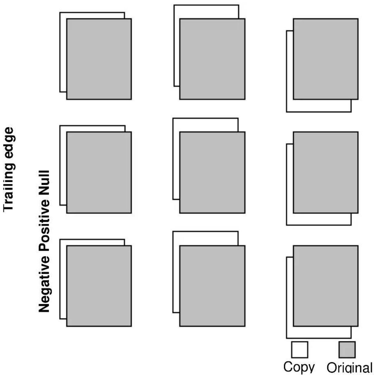
Increasing the copy length to accommodate for a filing strip is possible by selecting a positive leading/trailing edge.
If you don't want the filing strip to show on the copy, it is possible to remove it, by selecting a negative leading or trailing edge. The adjustment steps are indicated on the operating panel, expressed in millimetres or inches.
Adjusting the leading/trailing edge
1 Press the 'edge' button to toggle between leading and trailing edge.
2 Press the ‘up’ or ‘down’ button to select the the required leading/trailing edge value. The length of the currently selected edge is shown in the display. If you make adjustments using this button the indications above the button are flashing. If the adjustment differs from the default setting, the indication remains on. You confirm the setting by pressing the zoom, edge, cut, media or start button.
Attention: Be aware that decreasing the edges too much may result in a loss of information.
The behaviour of adjusting the leading/trailing edge is different, depending on using roll feed or manual feed (see ‘Leading/trailing edge when copying on rolls of paper’ on page 61) and ‘Leading/trailing edge when copying on sheet of paper’ on page 62).
Leading edge
Null Positive Negative

[24] Using rolls
Leading edge
Null Positive Negative
flowchart
graph TD
    A["Trailing edge"] --> B["Negative Positive Null"]
    B --> C["Copy"]
    B --> D["Original"]
    E["Trailing edge"] --> F["Copy"]
    E --> G["Original"]
    H["Trailing edge"] --> I["Copy"]
    H --> J["Original"]
    K["Trailing edge"] --> L["Copy"]
    K --> M["Original"]
    N["Trailing edge"] --> O["Copy"]
    N --> P["Original"]
[25] Using sheets
Modifying the exposure
The automatic exposure setting ensures the production of background-free copies of most line drawings. In this case the automatic background compensation is activated.
The background is constantly measured during scanning of the original. However, the result of some originals may not match your requirements.
Normally the automatic background compensation is active and the exposure level is 0.
▼ Manually adjusting the exposure
In case you still have background on the copy:
1 Leave your originals in the scanner.
2 Adjust the exposure level with the 'lighter' button.
3 Press the 'start' button.
In case weak information is not visible anymore:
1 Leave your originals in the scanner.
2 Adjust the exposure level with the 'darker' button.
3 Press the 'start' button.
If the result still does not match your requirements:
1 Leave your originals in the scanner.
2 Deactivate the automatic exposure background compensation by pressing the ‘auto exposure’ button. The background is not measured anymore during scanning of the original.
3 Adjust the background level of the copy using the 'lighter' and 'darker' buttons.
4 Press the 'start' button.
Inverted copies/Blueprints
To copy old blueprints you can select the invert copy mode. To prevent using this option by mistake, this function is protected. You must first feed the original and then press the ‘correction’ and the ‘zoom’ button simultaneously.
▼ Making invert copies
1 Feed the original.
2 Press the ‘correction’ and the ‘zoom’ button at the same time.
The invert copy mode is now active. The copy quantity is reset to 1 (cannot be changed) and will flash. The auto exposure is automatically switched off.
3 Press the 'start' button.
Remove the original after it is returned. The invert copy mode is not longer active.
Poster mode
When copying originals with large black areas Poster mode ensures an optimal copy quality by increasing the density of the copy. If required, select this option.
▼ Activating Poster mode
1 Press the ‘lighter’ and ‘darker’ button simultaneously.
The Exposure light will flash. The Poster mode is now active.
2 If required you can still modify the exposure level.
3 Feed the original.
4 Press the 'Start' button.
▼ De-activating the Poster mode
1 Press the ‘lighter’ and ‘darker’ button again at the same time.
2 Press the 'Stop/Correction' button.
Chapter 5 Print jobs
This chapter describes how to print files.

Printing files
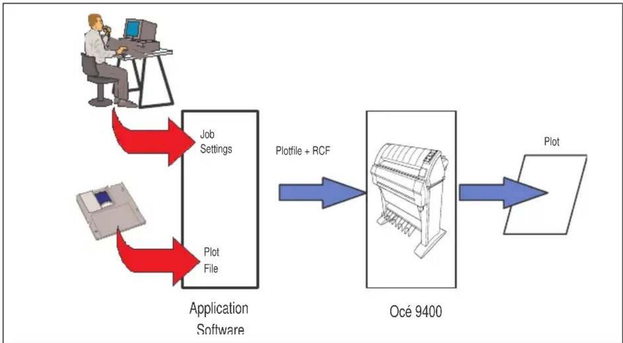
The Océ 9400 can be connected to a host environment, which may be either a stand alone PC/Workstation or a PC/Workstation connected to a network. It accepts various standard format CAD/CAM vector and EDMS raster data files from the host environment and converts these into high quality plots (see figure 26).
flowchart
graph LR
    A["User"] --> B["Application Software"]
    C["User"] --> B
    B --> D["Plotfile + RCF"]
    B --> E["Océ 9400"]
    E --> F["Plot"]
[26] Dataflow to the Océ 9400
When an Océ 9400 receives vector (HP-GL, HP-GL/2, VDF, BGL, Calcomp 906/907), raster (HP-RTL, TIFF, CALS) or PostScript (PostScript level 2 optional) data it will generate a plot with the settings (e.g. number of copies, plotter emulation etc.) as specified on the operator console in Program Mode.
In order to gain maximum flexibility, each plot job can be preceded by remote control commands to specify the settings to be used for this job. This so-called header contains job and file specific settings (e.g. number of copies) in Remote Control Format (RCF) which overrule the settings programmed in Program Mode.
In order to compose such a header, you may:
■ Compose the header within your application. Please refer to the Océ 9400 Programmers Manual for details about the RCF syntax and functionality.
- Use an Océ Windows and/or Autocad ADI driver to generate both a plottable file (e.g. HP-RTL, HP-GL/2) and the appropriate header with RCF-commands. Please refer to the Océ Windows / Autocad Driver documentation for more details.
- Use the Océ Windows application Plot Director in order to compose jobs of plotable files in a very flexible and user friendly way. Please refer to the Océ Plot Director manual for more detail.
Océ applications
The following application is available: Plot Director (MS-Windows 3.x, NT and 95)
Océ drivers
The following drivers are available: ADI driver for AutoCAD R12. (MS-DOS, MS-Windows 3.x), AutoCAD R13 (MS-DOS, Windows 3.x, NT and 95) Windows Printing Solution (Windows 3.x, NT and 95). PostScript driver (Windows 3.x, NT, 95 and Macintosh)
Cut method
This setting can be used to select standard cut or synchro cut (see ‘Order of standard sizes for using standard cut’ on page 143).
Note: The values selected for leading or trailing edge are taken into account when using Synchro Cut.

Programming cut method
1 Press Regulator the main menu.
2 Select MEDIA SETTING item using the ◀ or button.
3 Press next select the MEDIA SETTING menu.
4 Select the PLOT POSITION item using the ◄ or button.
5 Press next to the PLOT POSITION menu.
6 Select the CUT METHOD item using the ◀ or button.
7 Press next/selecthe CUT METHOD menu.
8 Select the desired cut method using the or button.
9 Press next/selenm the selected cut method.
10 Press Programme the main menu.
Plot Center
This setting can be used to enable or disable centering of the plot on the paper. If center is off, the plot will be positioned in the left top corner of the page.
If Standard Cut is selected, the plot is printed and the media is cut according to the standard cut functionality. If Plot Center in ON, the plot is shifted up/down and left/right to be centered on the selected bounding box.
Note: If you print a plot longer than standard size, the machine automatically switches to synchro cut, to prevent you from loosing information.
If Synchro Cut is selected, the bounding box of the plot sets the hard clip limits. If Plot Center is ON, the plot is shifted left/right to be centered on the page.
Programming Plot Center
1 Press Programmer the main menu.
2 Select MEDIA SETTING item using the or button.
3 Press next select the MEDIA SETTING menu.
4 Select the PLOT POSITION item using the ◄ or button.
5 Press TextSelecthe PLOT POSITION menu.
6 Select the PLOT CENTER item using the ◀r button.
7 Press next to the PLOT CENTER menu.
8 Select the ON/OFF using the or button.
9 Press next selentm the setting.
10 Press Programme the main menu.
Leading/trailing edge
The leading edge setting can be used to add a white strip at the top of the image. The page length will increase accordingly.
The trailing edge setting can be used to add a white strip at the end of the image. The pagelength will increase accordingly
Note: The leading/trailing edge option only works if the cut method is set to synchro cut.
The value for the trailing or leading edge can be set between -80 to 80 mm (in steps of 5 mm) or -3 to +3 inch (in steps of 14 inch).
▼ Programming leading or trailing edge
1 Press Progrator the main menu.
2 Select MEDIA SETTING item using the ◀ or button.
3 Press next selecthe MEDIA SETTING menu.
4 Select the PLOT POSITION item using the or button.
5 Press next select the PLOT POSITION menu.
6 Select the TRAILING or LEADING EDGE item using the ◀ or button.
7 Press next select the TRAILING or LEADING EDGE menu.
8 Select the required value using the ◀ or button.
9 Press next/second the value.
10 Press Programm the main menu.
Demo plot
Having installed the Océ 9400 it is recommended to check the printer and the controller.
▼ Making a demo plot
1 Press Progrator the main menu.
2 Select the PLOT item using the ◀ or button.
3 Press (next/selecthe) PLOT menu.
4 Select the DEMO PLOT item using the or button.
5 Press rlexpselecthe demo plot
6 Press Programs the main menu.
Cancel plot
If you want to cancel the a plot before printing starts:
▼ Cancelling a plot
1 Press cancel/continue.
The printer stops. It is possible that the plot will not completely be printed. The paper is always ejected.
Chapter 6 Upload jobs
This chapter describes the digitizing analogue drawings while using the Océ 9400.

Introduction
The Océ 9400 can be used also for digitizing analogue drawings and uploading them to a host computer using a SCSI-interface. Therefore the Scan to file option is required.
This option consists of the following parts:
■ OLB SCSI-board to be inserted in the Océ 9400 controller
■ Scan Station software for the Océ 9400
■ SCSI-board (option) in the PC to connect the Océ 9400
▼ Making uploads
After everything has been installed correctly on the Oce 9400 and on the PC both systems should be connected with SCSI-cable and the uploading can start.
1 Switch on the Oce 9400 and the PC.
2 Start the Upload application and set all scan parameters as required and proceed as follows. (Also refer to the Scan Station manual).
As soon as the upload is started with the application, the Océ 9400 printer panel displays “SCANMODE” after which the system is ready to make uploads.
3 Insert an original in the scanner, make the required settings on the scanner's operating panel and press the Start-button on the scanner (see also notes below).
4 When the original has been scanned and transported back to its start position, a checkplot is made. If this has been selected to do so in the Scan Station application. The checkplot is made on the media which has been selected on the scanner's operating panel.
5 Then the Océ 9400 controller creates the file which will be uploaded to the PC. When the file is uploaded it can be viewed on the PC.
6 Settings can be modified on the PC and on the scanner and a next original can be scanned, or the current original can be re-scanned with the new settings.
7 The Upload process can be stopped on the PC and the Océ 9400 is free for print and/or copy jobs. (Also refer to the Scan Station manual)
The following buttons are disabled on the Oce 9400 scanner operating panel when it is in Upload mode:
- Cut
■ Edge, except negative leading edge - Zoom
- Display of number of copies is fixed to "1" if checkplot is enabled on the Scan Station application.
The following buttons are disabled on the Oce 9400 scanner operating panel when it is in Upload mode and checkplot is disabled:
■ Media
■ + and - for number of copies
■ Display for number of copies is cleared
The size of the drawing which can be uploaded (and printed with checkplot) is limited by the amount of memory which is installed in the Océ 9400 controller and the bitmap partitioning (see ‘Setting the bitmap buffer’ on page 32).
Chapter 7 Customizing the printer
How to set the Océ 9400 defaults to accommodate print jobs that you use most frequently.

Defining pen settings
When printing files, the pen settings can be changed in the pen menu. You can change the default width and pattern for each pen number. These settings apply to all vector languages: HP-GL, HP-GL/2 CalComp, VDF and BGL.
Pen width can be defined from 0.08 up to 10.75 mm (0.0031" to 0.423"). By default all pen widths are set to 0.25 mm (0.009"). Adjustment can be made in steps of 0.01 mm.
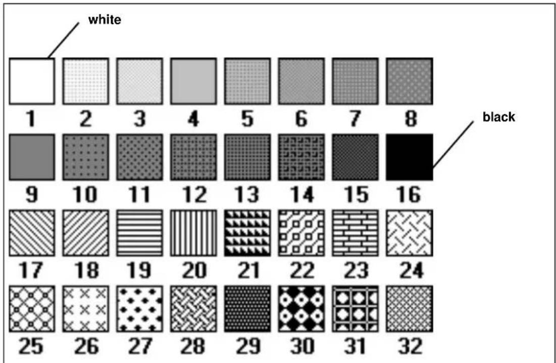
A pen can be selected by the plot file to draw a line or to fill a polygon. All lines or polygons on the plot can be drawn with a predefined pattern or shade of grey. Default is pen pattern 16. The following pen patterns are available.
The rendering function can be divided into clustered or cloud. With this option you can change the first 16 pen patterns into another 16 gray-shaded pen patterns.
Attention: Clustered must be used if your originals contain big gray areas. Use cloud to get an optimal result with line drawings.
heatmap
| | 1 | 2 | 3 | 4 | 5 | 6 | 7 | 8 | |---|---|---|---|---|---|---|---|---| | white | □ | □ | □ | □ | □ | □ | □ | □ | | black | □ | □ | □ | □ | □ | □ | □ | □ | | 1 | □ | □ | □ | □ | □ | □ | □ | □ | | 2 | □ | □ | □ | □ | □ | □ | □ | □ | | 3 | □ | □ | □ | □ | □ | □ | □ | □ | | 4 | □ | □ | □ | □ | □ | □ | □ | □ | | 5 | □ | □ | □ | □ | □ | □ | □ | □ | | 6 | □ | □ | □ | □ | □ | □ | □ | □ | | 7 | □ | □ | □ | □ | □ | □ | □ | □ | | 8 | □ | □ | □ | □ | □ | □ | □ | □ | | 9 | □ | □ | □ | □ | □ | □ | □ | □ | | 10 | □ | □ | □ | □ | □ | □ | □ | □ | | 11 | □ | □ | □ | □ | □ | □ | □ | □ | | 12 | □ | □ | □ | □ | □ | □ | □ | □ | | 13 | □ | □ | □ | □ | □ | □ | □ | □ | | 14 | □ | □ | □ | □ | □ | □ | □ | □ | | 15 | □ | □ | □ | □ | □ | □ | □ | 16 | | 16: Black | 17, 18, 19, 20, 21, 22, 23, 24 | 25, 26, 27, 28, 29, 30, 31, 32 | 25, 26, 27, 28, 29, 30, 31, 32[27] Available pen patterns

[28] The rendering function gray shaded patterns

Defining the pen settings
1 Press Recogner the main menu.
2 Select the CONFIGURATION item using the or button.
3 Press (next/selecthe) CONFIGURATION menu.
4 Select the PEN MENU option using the ◀ or button.
5 Press next/select the PEN MENU.
For each pen to set up perform as follows:
6 Select the PEN NUMBER item using the ◀ or button.
7 Press (next/selecthe) PEN NUMBER menu.
8 Select the required PEN NUMBER using the ◄ or button
9 Press next/select the selected pen number.
10 Press (previous) enter the pen menu.
From this menu:
11 Select the PEN WIDTH item using the ◀ or button.
12 Press (next/selecthe) PEN WIDTH menu.
13 Select the required pen width using the ◀ or button.
14 Press (next/select) the selected pen width.
15 Press previous enter the pen menu.
16 Select the PEN PATTERN item using the or button.
17 Press next/select the PEN PATTERN menu.
18 Select the appropriate pen pattern using the ◀ or button.
19 Press next/selectn the selected pen pattern.
Having programmed all pen settings:
20 Press Programs the main menu.

Defining rendering
1 Press Recogner the main menu.
2 Select the CONFIGURATION item using the ◄ or button.
3 Press next to select the CONFIGURATION menu.
4 Select the RENDERING option using the ◀ or button.
5 Press next/selecthe RENDERING MENU.
6 Select the required option clustered or cloud using the ◀ or button.
7 Press next/select the selected option.
8 Press Poolgram the main menu.
Defining language settings
The Océ 9400 accepts print files in various data formats (languages). You can change the settings for PostScript, VDF, BGL, HP-GL, HP-GL/2, HP-RTL, CalComp, CALS, TIFF or EDMICS.
Automatic language sensing
Automatic language sensing (ALS) is the mechanism which the system uses to detect the language (data format) of a file for which the format has not been specified in the file header. ALS scans the file contents for clues about the data format. Automatic language sensing can be switched on/off. By default ALS is on.
ALS enables the printer to switch between:
- Océ languages (VDF and BGL), PostScript, HP-GL, HP-GL/2, HP-RTL, CalComp, CALS, TIFF or EDMICS
Use the ALS formats parameter to define which data formats are to be searched for in the print files.
Note: When using ALS, it is very important that every print file terminates with an end of print instruction.
▼ Activating ALS
1 Press program the main menu.
2 Select the CONFIGURATION item using the or button.
3 Press NextSelect the CONFIGURATION menu.
4 Select the DATA FORMAT item using the ◄ or button.
5 Press next/redefthe DATA FORMAT menu.
6 Select the SELECT FORMAT item using the ◀ or button.
7 Press (next/selecthe) SELECT FORMAT menu.
8 Select the AUTO item using the or button.
9 Press next/selept this mode.
10 Press program the main menu.
Data format recognition
To optimize your printer's language recognition and reduce the risk of errors, each of the above mentioned data formats can be individually set ON or OFF. Default is on.
▼ Optimizing data format recognition
1 Press Progrator the main menu.
2 Select the CONFIGURATION item using the ◀ or button.
3 Press next select the CONFIGURATION menu.
4 Select the DATA FORMAT item using the or button.
5 Press next-selecto DATA FORMAT menu.
6 Select the AUTO MENU item using the or button.
7 Press next selecthe AUTO MENU menu.
For each graphics language to set up perform as follows:
8 Select the required graphics language item using the ◄ or button.
9 Press next to the required language menu.
10 Select YES or NO using the ◀ or button.
11 Press next/selectm the selected setting.
12 Press previous enter the graphics language menu.
Having programmed all languages:
13 Press Programme the main menu.
Manual data format selection
If required one of the data formats can be selected manually.
Note: ALS is not active.

Setting manual data format
1 Press Recogner the main menu.
2 Select the CONFIGURATION item using the or button.
3 Press next to the CONFIGURATION menu.
4 Select the DATA FORMAT item using the or button.
5 Press (next/selecthe) DATA FORMAT menu.
6 Select the SELECT FORMAT item using the or button.
7 Press next select the SELECT FORMAT menu.
8 Select the required language using the ◀ or button.
9 Press next/selectm the selected language.
10 Press poolgrave the main menu.
Note: When PostScript is selected no RCF header is recognized.
Océ languages (VDF/BGL)
Océ print origin
The starting position of the print on the paper depends on the print origin. You can choose between: upper right, upper left, center, lower right and lower left (see figure 29). Default is Lower right.
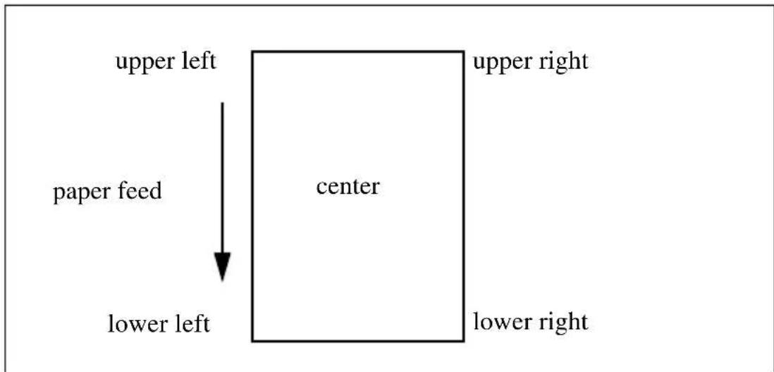
flowchart
graph TD
    A["paper feed"] --> B["center"]
    B --> C["upper left"]
    B --> D["upper right"]
    B --> E["lower left"]
    B --> F["lower right"]
[29] Print origin options
Defining the print origin
1 Press Progrator the main menu.
2 Select the CONFIGURATION item using the ◄ or button.
3 Press next selecthe CONFIGURATION menu.
4 Select the DATA FORMAT item using the ◄ or button.
5 Press Text Selecthe DATA FORMAT menu.
6 Select the OCE SETUP item using the ◀ or button.
7 Press next=selecthe OCE SETUP menu.
8 Select ORIGIN item using the or button.
9 Press next/selecthe ORIGIN menu.
10 Select the required origin using the ◀ or button.
11 Press next/selectm the selected origin.
12 Press Programme the main menu.
Océ step size
The Océ 9400 offers four different step sizes: 12.5 m , 25 m , 50 m and 100 m (see figure 30). Bear in mind that a wrong step size will affect the scale of your drawing. Default is 25.
For example: A drawing printed with 50 m step size as defined in the software. The scale is correct (A).
The same drawing printed with 100 m step size. The print is twice normal size (B).
The same drawing printed with 25 m step size. The print is half normal size (C).

[30] Step size

Defining the step size
1 Press (recognizer the main menu.
2 Select the CONFIGURATION item using the ◄ or button.
3 Press next/netecthe CONFIGURATION menu.
4 Select the DATA FORMAT item using the ◄ or button.
5 Press next/see the DATA FORMAT menu.
6 Select the OCE SETUP item using the or button.
7 Press next to the OCE SETUP menu.
8 Select the STEP SIZE item using the ◄ or button.
9 Press next/selecthe STEP SIZE menu.
10 Select the required step size using the or button.
11 Press to confirm the selected value.
12 Press Programs the main menu.
Océ pen priority
You can define pen parameters within the print file, from the printer control panel or in a remote configuration file. The pen priority option allows you to define which pen parameter set you want to use. Default is Language.
If Language is selected, the pen parameters defined in the data file will be used. If Setup is selected, the pen parameter defined on the printer operating panel, or in the optional remote configuration file, will be used.
▼ Defining pen priority Océ setup
1 Press program the main menu.
2 Select the CONFIGURATION item using the or button.
3 Press next to the CONFIGURATION menu.
4 Select the DATA FORMAT item using the ◄ or button.
5 Press (next/ selecting) DATA FORMAT menu.
6 Select the OCE SETUP item using the ◀ or button.
7 Press next to select the OCE SETUP menu.
8 Select the PEN PRIORITY item using the or button.
9 Press (next/selecthe) PEN PRIORITY menu.
10 Select the required pen priority setting using the or button.
11 Press next/selectm the selected pen priority.
12 Press Programs the main menu.
HP-GL
With this function you can define the settings for the HP-GL file types.
HP-GL print origin
The starting position of the print on the paper depends on the print origin. You can choose between: upper right, upper left, center, lower right and lower left (see figure 29 on page 82). Default is Center.
▼ Defining the HP-GL print origin
1 Press Prognar the main menu.
2 Select the CONFIGURATION item using the or button.
3 Press next to the CONFIGURATION menu.
4 Select the DATA FORMAT item using the ◄ or button.
5 Press (next to select the DATA FORMAT menu.
6 Select the HP-GL SETUP item using the ◄ or button.
7 Press next to the HP-GL SETUP menu.
8 Select the ORIGIN item using the or button.
9 Press next/select the ORIGIN menu.
10 Select the required origin using the ◄ or button.
11 Press next/second the selected origin.
12 Press program the main menu.
HP-GL page advance
In HP-GL the Select Pen Zero (SP0) command can be interpreted in two ways:
If page advance is set to yes, the printer responds to the HP-GL instruction SP0 as an indication of end of print.
If page advance is set to no, the printer responds to the HP-GL instruction SP0 as select pen zero. Any vectors following the SP0 will be printed with the default pen attributes of width = 3 pixels and pattern = 16 (black). Default is Yes.
Setting the HP-GL page advance
1 Press Regulator the main menu.
2 Select the CONFIGURATION item using the or button.
3 Press next/selecthe CONFIGURATION menu.
4 Select the DATA FORMAT item using the ◄ or button.
5 Press next select the DATA FORMAT menu.
6 Select the HP-GL SETUP item using the ◄ or button.
7 Press next to the HP-GL SETUP menu.
8 Select the required PAGE ADVANCE item using the ◄ or button.
9 Press next select the PAGE ADVANCE menu.
10 Select YES or NO using the ◀ or button.
11 Press next select the selected setting.
12 Press Programme the main menu.
Merge mode
This option determines what happens when two or more colours intersect at the same point of a plot, especially in area fills. Default setting is On.
Merge Off Only the last colour specified is printed for a given line or area. The other colours specified for the same line or area are transparent.
Merge On All the specified colours are blended together.
Setting the merge mode
1 Press Progrator the main menu.
2 Select the CONFIGURATION item using the or button.
3 Press Text/Selecthe CONFIGURATION menu.
4 Select the DATA FORMAT item using the ◀ or button.
5 Press (text/selecthe) DATA FORMAT menu.
6 Select the HP-GL SETUP item using the or button.
7 Press next/sétecthe HP-GL SETUP menu.
8 Select the MERGE item using the or button.
9 Press to enter the MERGEmenu.
10 Select YES or NO using the ◀ or button.
11 Press next/selectm the selected setting.
12 Press Programme the main menu.
HP-GL/2
HP-GL/2 print origin
The starting position of the print on the paper depends on the print origin. You can choose between: upper right, upper left, center, lower right and lower left (see figure 29 on page 82). Default is Lower right.
▼ Defining the HP-GL/2 print origin
1 Press Prograder the main menu.
2 Select the CONFIGURATION item using the or button.
3 Press next to the CONFIGURATION menu.
4 Select the DATA FORMAT item using the or button.
5 Press (next to select the DATA FORMAT menu.
6 Select the HP-GL/2 SETUP item using the or button.
7 Press next to the HP-GL/2 SETUP menu.
8 Select the ORIGIN item using the or button.
9 Press next/select the ORIGIN menu.
10 Select the required origin item using the ◀ or button.
11 Press next/second the selected origin.
12 Press Program the main menu.
HP-GL/2 page advance
In HP-GL the SP0 command can be interpreted in two ways, depending on the printer being emulated.
If page advance is set to yes, the printer responds to the HP-GL instruction SP0 as an indication of end of print.
If page advance is set to no, the printer responds to the HP-GL instruction SP0 as select pen zero. Any vectors following the SP0 will be printed with the default pen attributes of width = 3 pixels and pattern = 16 (black). Default is yes.
Setting the HP-GL/2 page advance
1 Press Prograder the main menu.
2 Select the CONFIGURATION item using the or button.
3 Press next/selecthe CONFIGURATION menu.
4 Select the DATA FORMAT item using the ◀ or button.
5 Press (next/ selecting) DATA FORMAT menu.
6 Select the HP-GL/2 SETUP item using the or button.
7 Press next/selecthe HP-GL/2 SETUP menu.
8 Select the PAGE ADVANCE item using the or button.
9 Press (next/selecthe) PAGE ADVANCE menu.
10 Select the required page advance using the ◀br button.
11 Press (next/select) to confirm the selected page advance.
12 Press (pogave the main menu.
HP-GL/2 pen priority
You can define pen parameters within the print file, from the printer control panel or in a remote configuration file. The pen priority option allows you to define which pen parameter set you want to use.
If Language is selected, the pen parameters defined in the data file will be used. If Setup is selected, the pen parameter defined on the printer operating panel, or in the optional remote configuration file, will be used. Default is Language.
▼ Defining pen priority HP-GL/2
1 Press Programm the main menu.
2 Select the CONFIGURATION item using the ◄ or button.
3 Press (next/selecthe) CONFIGURATION menu.
4 Select the DATA FORMAT item using the ◄ or button.
5 Press (next/ selecting) DATA FORMAT menu.
6 Select the HP-GL/2 SETUP item using the or button.
7 Press (next/ selecting) HP-GL/2 SETUP menu.
8 Select the PEN PRIORITY item using the ◄ or button.
9 Press (next/selecthe) PEN PRIORITY menu.
10 Select the required pen priority using the ◀ or button.
11 Press next/selectm the selected pen priority.
12 Press (Poolgrave the main menu.
Designjet compatibility
If you print a colour data file on a black and white printer the result may be not sufficient. If you emulate the HP 650C the information which is defined in colour is printed in black; if you emulate to print on the HP 750C the information which is defined in colour will be printed in gray scale levels.
▼ Defining Designjet compatibility
1 Press Recogner the main menu.
2 Select the CONFIGURATION item using the or button.
3 Press next to the CONFIGURATION menu.
4 Select the DATA FORMAT item using the or button.
5 Press next to the DATA FORMAT menu.
6 Select the HP-GL/2 SETUP item using the or button.
7 Press next/see the HP-GL/2 SETUP menu.
8 Select the DESIGNJET item using the ◀r button.
9 Press (next search) DESIGNJET menu.
10 Select the required designjet using the ◀ or button.
11 Press next/select the selected designjet.
12 Press (prograve the main menu.
Merge mode
This option determines what happens when two or more colours intersect at the same point of a plot, especially in area fills. Default setting is On.
Merge Off Only the last colour specified is printed for a given line or area. The other colours specified for the same line or area are transparent.
Merge On All the specified colours are blended together.
Setting the merge mode
1 Press Programm the main menu.
2 Select the CONFIGURATION item using the or button.
3 Press (next/selecthe) CONFIGURATION menu.
4 Select the DATA FORMAT item using the or button.
5 Press next/selecthe DATA FORMAT menu.
6 Select the HP-GL/2 SETUP item using the or button.
7 Press (next/selecthe) HP-GL/2 SETUP menu.
8 Select the MERGE item using the or button.
9 Press next/select the MERGE menu.
10 Select YES or NO using the ◀ or button.
11 Press next/selectm the selected setting.
12 Press Programme the main menu.
HP-RTL
HP-RTL is a subset of HP-GL/2. Hence, all HP-RTL plot data files must start with ESC%-1BBPIN: or BPIN.
To use HP-RTL, the SELECT FORMAT should be set to AUTO or HP-GL/2 on the operating panel or HP-GL/2 must be selected via a remote control file.
Note: HP-RTL plot data files must end with ESC%OB; PG; which will switch the printer back to HP-GL/2 format mode. Without this command, the plot results will be unpredictable and the printer will stop.
The following HP-RTL statements have no meaning on the Océ 9400 and will be treated as no-ops: ESC*v#a, ESC*v#b, ESC*v#c, ESC*v#i, ESC*v#W[data], ESC*b#l and ESC&b#V[data].
CalComp
The Océ 9400 offers compatibility with the CalComp graphics language.
CalComp print origin
The starting position of the drawing position on the paper depends on the print origin: upper right, upper left, center, lower right and lower left (see figure 29 on page 82).
Default CalComp origin is Lower right. This print origin is used for all CalComp files, no matter whether select format was set to CalComp or Auto or a remote control command for CalComp was sent.
▼ Defining the print origin
1 Press Prograder the main menu.
2 Select the CONFIGURATION item using the or button.
3 Press (next/search) CONFIGURATION menu.
4 Select the DATA FORMAT item using the or button.
5 Press (next/ selecting) DATA FORMAT menu.
6 Select the CALCOMP SETUP item using the ◀ or button.
7 Press (next/setsethe) CALCOMP SETUP menu.
8 Select the ORIGIN item using the or button.
9 Press (next/bedethe) ORIGIN menu.
10 Select the required origin item using the or button.
11 Press to confirm the selected origin.
12 Press Programs the main menu.
Checksum parameter
The checksum parameter is significant in all cases when CalComp format is selected or auto-recognized when select format is set to Auto or a remote control command for CalComp was sent. Default is Yes.
▼ Defining the checksum parameter
1 Press Prograder the main menu.
2 Select the CONFIGURATION item using the or button.
3 Press next/selecthe CONFIGURATION menu.
4 Select the DATA FORMAT item using the <br button.
5 Press (next/sélecthe) DATA FORMAT menu.
6 Select the CALCOMP SETUP item using the or button.
7 Press next selecthe CALCOMP SETUP menu.
8 Select the CHECKSUM item using the or button.
9 Press Text/Selecthe CHECKSUM menu.
10 Select YES or NO using the ◀ or button.
11 Press next/select the selected setting.
12 Press Programme the main menu.
CalComp pen priority
You can define pen parameters within the print file, from the printer control panel or in a remote configuration file. The pen priority option allows you to define which pen parameter set you want to use.
If Language is selected, the pen parameters defined in the data file will be used. If Setup is selected, the pen parameter defined on the printer operating panel, or in the optional remote configuration file, will be used. Default is Language.
1 Press Program the main menu.
2 Select the CONFIGURATION item using the ◀ or button.
3 Press next/selecthe CONFIGURATION menu.
4 Select the DATA FORMAT item using the ◄ or button.
5 Press next/selecthe DATA FORMAT menu.
6 Select the CALCOMP SETUP item using the or button.
7 Press next/selecthe CALCOMP SETUP menu.
8 Select the PEN PRIORITY item using the ◀ or button.
9 Press (text/selecthe) PEN PRIORITY menu.
10 Select the required pen priority using the ◀ or button.
11 Press to confirm the selected pen priority.
12 Press Programme the main menu
Merge mode
This option determines what happens when two or more colours intersect at the same point of a plot, especially in area fills. Default setting is On.
Merge Off Only the last colour specified is printed for a given line or area. The other colours specified for the same line or area are transparent.
Merge On All the specified colours are blended together.
Setting the merge mode
1 Press Progrator the main menu.
2 Select the CONFIGURATION item using the ◀ or button.
3 Press next selecthe CONFIGURATION menu.
4 Select the DATA FORMAT item using the ◄ or button.
5 Press next-selecthe DATA FORMAT menu.
6 Select the CALCOMP SETUP item using the ◀ or button.
7 Press next select the CALCOMP SETUP menu.
8 Select the MERGE item using the ◄ or button.
9 Press next-selecthe MERGE menu.
10 Select YES or NO using the ◀ or button.
11 Press next/selectm the selected setting.
12 Press Programs the main menu.
End of Message parameter
The End of Message (EOM) parameter is significant in all cases where CalComp format is selected or auto-recognized when select format is set to Auto or a remote control command for CalComp was sent.
Possible values range from 0 to 31_DEC inclusive. The selected value is the decimal equivalent of the byte indicating the end of the data sequence. It should be a unique character in the character set used for coding the data. The default EOM is 3.
Setting the End of Message parameter
1 Press Progrator the main menu.
2 Select the CONFIGURATION item using the or button.
3 Press next select the CONFIGURATION menu.
4 Select the DATA FORMAT item using the or button.
5 Press Text Select the DATA FORMAT menu.
6 Select the CALCOMP SETUP item using the ◀ or button.
7 Press next selecthe CALCOMP SETUP menu.
8 Select the END OF MESSAGE item using the or button.
9 Press next select the END OF MESSAGE menu.
10 Select the required value using the ◀ or button.
11 Press to confirm the selected value.
12 Press Programs the main menu.
Synchronization code parameter
The synchronization code parameter is significant in all cases where CalComp format is selected or auto-recognized when select format is set to Auto or a remote control command for CalComp was sent.
Possible values range from 0 to 63 _DEC inclusive. The selected value is the decimal equivalent of the byte to be interpreted as the beginning of a block of print data. The default synchronization code is 2.
Setting the synchronization code parameter
1 Press Program the main menu.
2 Select the CONFIGURATION item using the or button.
3 Press next to select the CONFIGURATION menu.
4 Select the DATA FORMAT item using the ◄ or button.
5 Press next to select the DATA FORMAT menu.
6 Select the CALCOMP SETUP item using the or button.
7 Press (next/selecthe) CALCOMP SETUP menu.
8 Select the SYNC CODE item using the or button.
9 Press next/select the SYNC CODE. menu.
10 Select the required sync code using the or button.
11 Press next/selectm the selected sync code.
12 Press Programs the main menu.
Double synchronization code parameter
The synchronization code parameter is significant in all cases where CalComp format is selected or auto-recognized when select format is set to Auto or a remote control command for CalComp was sent.
The double synchronization parameter allows one or two synchronization characters to identify the beginning of a message of print data. If set to double synchronization, the same character is sent twice. Default is No.
Setting the double synchronization code parameter
1 Press Progrator the main menu.
2 Select the CONFIGURATION item using the or button.
3 Press (next/selecthe) CONFIGURATION menu.
4 Select the DATA FORMAT item using the or button.
5 Press (next/retesthe) DATA FORMAT menu.
6 Select the CALCOMP SETUP item using the ◀ or button.
7 Press next/selecthe CALCOMP SETUP menu.
8 Select the DOUBLE SYNC item using the ◀ or button.
9 Press (next/setathe) DOUBLE SYNC menu.
10 Select the required double sync using the ◀ or button.
11 Press to confirm the selected value.
12 Press (pocgrave the main menu.
CalComp step size
If the data format type is set to CalComp (manual, auto selection or remote control command), seven steps are provided (100 dpi to 4064 dpi). The default is 2032.

Setting the appropriate step size
1 Press Programm the main menu.
2 Select the CONFIGURATION item using the ◄ or button.
3 Press (next/selecthe) CONFIGURATION menu.
4 Select the DATA FORMAT item using the or button.
5 Press next/selectc DATA FORMAT menu.
6 Select the CALCOMP SETUP item using the or button.
7 Press (next/selecthe) CALCOMP SETUP menu.
8 Select the STEP SIZE item using the ◄ or button.
9 Press next/select the STEP SIZE menu.
10 Select the required value using the ◀ or button.
11 Press next/selectm the selected value.
12 Press Programs the main menu.
Raster formats
CALS
CALS (Computer Aided Acquisition and Logistics Support).
The Océ 9400 printer supports CALS type 1 files. (Untiled, compatible with CCITT Group 4 format).
NIRS
NIRS is a sub-set of CALS. The data format consists of a CALS header followed by a NIRS header followed by TIFF raster data.
TIFF
TIFF (Tagged Information File Format).
The Océ 9400 printer supports the following TIFF 6.0 files.
- Uncompressed
- Compressed:
PACKBIT byte oriented, runlength Modified Huffman (based on CCITT G3 1D)
CCITT Group 3 1 D and 2 D, runlength CCITT Group 4.
C4 (EDMICS)
C4 data format consists of a header followed by compressed CCITT 4 raster data.
Note: For the above raster languages no specific settings are necessary.
PostScript level 2
The Océ PostScript level 2 printer option can be used to print PostScript files on the Océ 9400. Océ provides host software to print from Windows or Macintosh applications.
This enables your printer to become a true wide format printer, producing monochrome posters from Illustrator, Word, Excel, QuarkXpress, Powerpoint, Pagemaker etc. as well as CAD or electronic design applications, among others.
Your PostScript document can be printed on any PostScript printer and the output should look the same. The Océ 9400 PostScript driver takes care of translating the application's internal data into PostScript, and it also makes sure you can select printer features in a simple way.
PostScript data format selection
When the PostScript option is installed, your printer will automatically recognize the PostScript language sent to the printer.
Note: When you are using the EtherTalk connection, you must select PostScript on the operating panel (via Ethernet - Print Server option).
Note: It is very important that every print file terminates with an end of print instruction. The PostScript end of print instruction is “Ctrl D”.
If there are files in the Media Saver, they will be flushed (printed) before the PostScript file is interpreted.
If your print is not recognized correctly, send it again with the appropriate data format selected on the control panel or in a remote control file.
Manual data format selection
You must manually setup the printer to PostScript when you want to use interactive mode when using Serial or Ethertalk option (specially for Macintosh). Refer to 'Setting manual data format' on page 81.
PostScript page layout
The orientation of the printed page on the roll can be either landscape or portrait.

Selecting the PostScript page layout
1 Press Prograder the main menu.
2 Select the CONFIGURATION item using the or button.
3 Press next to the CONFIGURATION menu.
4 Select the DATA FORMAT item using the ◄ or button.
5 Press (next to date) DATA FORMAT menu.
6 Select the PS SETUP item using the or button.
7 Press next to the PS SETUP menu.
8 Select the PAGE LAYOUT item using the ◄ or button
9 Press (next/Select) PAGE LAYOUT menu.
10 Select the required page layout using the ◀ or button.
11 Press next/second the selected page layout.
12 Press (prograve the main menu.
Default PostScript page size
This option indicates the dimensions of the paper on which your document will be printed. (For example D, A1, A4, etc.). This is useful only in the case where the format is not specified in the PostScript file.

Selecting the default PostScript page size
1 Press Pognar the main menu.
2 Select the CONFIGURATION item using the ◀ or button.
3 Press (next/selectc) CONFIGURATION menu.
4 Select the DATA FORMAT item using the or button.
5 Press (next/selecthe) DATA FORMAT menu.
6 Select the PS SETUP item using the ◀ or button.
7 Press next to the PS SETUP menu.
8 Select the DEF PAGE SIZE item using the or button.
9 Press (next/selecthe) DEF PAGE SIZE menu.
10 Select the required page size using the ◀ or button.
11 Press to confirm the selected page size.
12 Press Programs the main menu.
Note: In case of conflict, the page size defined in the PostScript driver will have priority.
Manual feed and Autoscale-to-format are not supported by the PostScript driver. These functions can be activated in the normal way, from the printer's operating panel.
Chapter 8 Advanced printer menu functions
This chapter describes the more advanced print functions.

End of plot time out
Normally, a print file will end with an instruction which tells the printer that the file is finished.
However, some print data files do not have an end of print instruction. In this case, the print will be considered as ‘finished’, when the printer does not receive any more graphic commands.
The print time out option, sets the delay after which the print will be considered as finished. You can choose between: 15, 30, 180 and 500 seconds. Default is 180.
Defining the end of plot time out
1 Press to enter the main menu.
2 Select the CONFIGURATION item using the or button.
3 Press (next/select the) CONFIGURATION menu.
4 Select the DATA FORMAT item using the or button.
5 Press (next select the DATA FORMAT menu.
6 Select the PLOT TIME OUT item using the or button.
7 Press (next/selecthe) PLOT TIME OUT menu.
8 Select the required plot time out using the ◀ or button.
9 Press next/selectm the selected plot time out.
10 Press Programs the main menu.
Selecting the media saver
The Océ 9400 offers two options for optimizing media usage for printing: Nesting and Autoposition. This applies for vector and raster formats. The media saver can also be set off.
Media saver is flushed:
■ after a time out
■ when a copy job is interrupting the printing process
■ when selecting another roll or manual feed
- by the flush media saver on the printer operating panel also refer to ‘Flush media saver’ on page 107.
Note: When automatic roll selection is used, the media saver is not active.
To use the media saver the following conditions must be set:
- cut methods = synchro
- center = off
■ leading- and trailing edge = 0.
Nesting
When nesting is selected, prints are stored in queues in the printer's memory, according to their size: A4 or A, A3 or B, A2 or C and mixed A4/A3. When the queue is full, the drawings are printed across the full width of the media.
The minimum paper length is 420 mm, so when printing A3 landscape or A4, an extra white strip of paper appears at the end.
If the print is larger than A2 or C size it will not be stored in a queue, but will be printed normally. If prints are not standard ISO, ANSI or Architecture sizes, the next larger format will be used (see figure 31 on page 105).
▼ Selecting nesting
1 Press Program the main menu.
2 Select the CONFIGURATION item using the or button.
3 Press next/selecthe CONFIGURATION menu.
4 Select the PLOT MANAGER item using the or button.
5 Press next to the PLOT MANAGER menu.
6 Select the MEDIA SAVER item using the ◄ or button.
7 Press (next/selecthe) MEDIA SAVER menu.
8 Select the M/S MODE item using the ◀ or button.
9 Press next to select the M/S MODE menu.
10 Select the NESTING item using the ◀ or button.
11 Press next/select the required setting.
12 Press Programs the main menu.

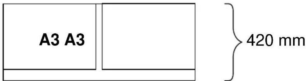

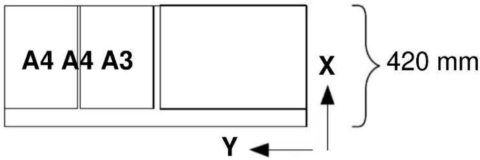
[31] Media saver nesting
Autoposition
This option ignores the origin declared in the print file and automatically shifts the print data to the lower right corner of the media. If necessary, prints are rotated 90° to better use the available media.
The autoposition feature is useful in reducing the clipping of a print and/or reducing wasted media.
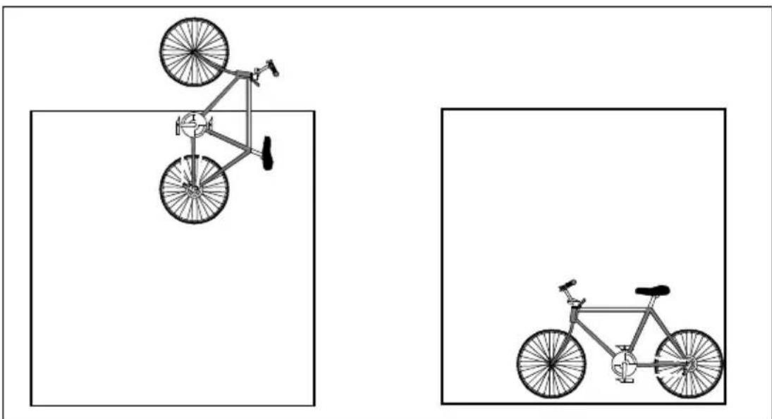
natural_image
Two bicycle illustrations shown in side-by-side views: one with a double bicycle above and one with a single bicycle below, both without any text or symbols.[32] Auto position to save media

Selecting autoposition
1 Press (Program) the main menu.
2 Select the CONFIGURATION item using the ◄ or button.
3 Press (next/second) CONFIGURATION menu.
4 Select the PLOT MANAGER item using the or button.
5 Press next to the PLOT MANAGER menu.
6 Select the MEDIA SAVER item using the ◄ or button.
7 Press (next/bate the) MEDIA SAVER menu.
8 Select the M/S MODE item using the ◀ or button.
9 Press (next/batch) M/S MODE menu.
10 Select the AUTO POSITION item using the or button.
11 Press next/elect the required setting.
12 Press the main menu.

Deselecting the media saver
1 Use the above procedure and select the media saver off.
Media saver time out
As already explained in the previous section, when the media saver queue is full the drawings are printed. However, to prevent unnecessary delays for prints in partially full queues, a time out of 1 to 60 minutes can be set, after which the contents of the queue is printed.

Setting the media saver time out
1 Press (Reognar the main menu.
2 Select the CONFIGURATION item using the or button.
3 Press next to the CONFIGURATION menu.
4 Select the PLOT MANAGER item using the or button.
5 Press next/selecthe PLOT MANAGER menu.
6 Select the MEDIA SAVER item using the or button.
7 Press next to the MEDIA SAVER menu.
8 Select the M/S TIME OUT item using the or button.
9 Press next to the M/S TIME OUT menu
10 Select the required value using the ◀ or button.
11 Press next selectm the selected value.
12 Press (prograve the main menu.
Flush media saver
If a print which is being held in the media saver memory is required, it can be printed immediately.

Setting the flush media saver
1 Press (Prognar the main menu.
2 Select the FLUSH MSAVER item using the or button.
3 Press (next select the) file being held.
4 Press (pocgrave the main menu.
Media saver plot size
When the media saver is set to Nesting, you have three choices of paper size: STD NO CLIP The print is printed on the paper size selected. It is not clipped.
STD CLIPPED If necessary, the print is clipped to fit on the paper size selected.
NON STANDARD The print is drawn as defined in the print data file. Papersize depends on the size of the plot.
Default is NONSTANDARD.

Setting the media saver plot size
1 Press Prognator the main menu.
2 Select the CONFIGURATION item using the ◄ or button.
3 Press (next/selecthe) CONFIGURATION menu.
4 Select the PLOT MANAGER item using the ◄ or button.
5 Press next to the PLOT MANAGER menu.
6 Select the MEDIA SAVER item using the ◄ or button.
7 Press (next selection) MEDIA SAVER menu.
8 Select the M/S PLOT SIZE item using the or button.
9 Press (next/selecthe) M/S PLOT SIZE menu
10 Select the required setting using the ◀ or button.
11 Press next/select the selected setting.
12 Press (poolgrave the main menu.
Replot
Normally, once a file has been processed and printed it is discarded. The replot function overrules the discarding. To make extra copies/prints from the operating panel. You have to select REPLOT enable.
Default is off.

Enabling replot
1 Press Recogner the main menu.
2 Select the CONFIGURATION item using the or button.
3 Press (next to select the) CONFIGURATION menu.
4 Select the REPLOT item using the or button
5 Press next/selecthe REPLOT menu.
6 Select the required setting using the ◀ or button.
7 Press next/second the setting.
8 Press (prograve the main menu.
Setting the number of copies
This option enables you to print multiple prints of the file currently in the memory of the printer. Default is 0, maximum is 99 prints.
Note: This option is only active if replotting is enabled.
▼ Defining the number of prints
1 Press (Reognar the main menu.
2 Select the # COPIES item using the ◀ or button.
3 Press (next/select the # COPIES menu.
4 Select the required number of copies using the ◀ or button.
5 Press next/select the number of copies.
6 Press (Program the main menu.
Poster mode
It is advisable to enable the Poster mode when you have to make prints which contain large black areas.

Enabling Poster mode
1 Press Recogner the main menu.
2 Select the POSTER MODE item using the ◀ or button.
3 Press next/selecthe POSTER MODE menu.
4 Select the Poster mode on/off using the ◄ or button.
5 Press next/selectm the Poster mode.
6 Press Programs the main menu.
Note: This setting will be overruled by Plot Director, the drivers and the setting on the scanner operating panel.
Dump configuration
Dumping the configuration is an easy way to obtain a list of the current print settings on paper.
Note: The dump configuration cannot be performed while a file is being processed.
Dumping the configuration
1 Press (Reognar the main menu.
2 Select the CONFIGURATION item using the or button.
3 Press (next/selecthe) CONFIGURATION menu.
4 Select the UTILITIES item using the ◀ or button.
5 Press (next/selecthe) UTILITIES menu.
6 Select the DUMP CONFIG item using the or button.
7 Press (next/salactm) DUMP CONFIG.
8 Press (Program the main menu.
Transformation
With the Océ 9400 it is possible to change the position of the image on the print, such as: rotating and scaling of the image. This applies only for vector languages and when the media saver is switched off.
Print rotation
This function allows you to set the rotation applied to a print. Four values are possible: 0^ , 90^ , 180^ and 270^ . Default is 0^ . This function only applies for vector languages.
▼ Defining the print rotation
1 Press Recogner the main menu.
2 Select the CONFIGURATION item using the or button.
3 Press (next selection) CONFIGURATION menu.
4 Select the PLOT MANAGER item using the ◄r button.
5 Press next to select the PLOT MANAGER menu.
6 Select the TRANSFORM item using the or button.
7 Press next/ selecting TRANSFORM menu.
8 Select the ROTATION item using the ◀ or button.
9 Press next/select the ROTATION menu.
10 Select the required value using the ◀ or button.
11 Press next/selectm the setting.
12 Press poolrame the main menu.
Print scaling
The X-scale and Y-scale can be set individually to a value between 0.05 and 20.0. Default is 1.0. This function only applies for vector languages.
▼ Defining print scaling
1 Press Recogner the main menu.
2 Select the CONFIGURATION item using the or button.
3 Press next to select the CONFIGURATION menu.
4 Select the PLOT MANAGER item using the or button.
5 Press Next search the PLOT MANAGER menu.
6 Select the TRANSFORM item using the or button.
7 Press next/selecthe TRANSFORM menu.
8 Select the SCALING item using the ◀ or button.
9 Press next/selecthe SCALING menu.
10 Select the required scaling method using the ◀ or button.
11 Press next/select appropriate menu.
For each scaling method follow the next procedure:
12 Select the required setting using the ◀ or button.
13 Press next/selectm the setting.
14 Press (Poolgrave the main menu.
Note: If autoscale is selected, x-scaling and y-scaling are not applicable.
Autoscaling
The purpose of Autoscale is to get documents on exact ISO/ANSI/Architect formats. The scaling factor applied to the X and Y axis is the same. Before computing this scaling factor, an auto rotation could be performed to get the best autoscale.
The Media Saver and the Autoscaling Mode are controlled separately but do interact.
The Autoscale Mode can be activated in two ways;
■ autoscale to a predefined format (ISO/ANSI/Architect)
■ best fit.
The user can combine Autoscale and Autoposition: plost are first autoscaled (best fit or scale to format, if needed), and then autopositioned (if needed).
Fit to Format Mode:
All the drawings regardless their sizes, are reduced/enlarged to one specific standard size. This option could be combined with the Media saver possibilities.
The list of predefined formats depends on the media format selected on the printer operating panel.
Users can enlarge drwaings to poster size to make presentations to large audience. They can also reduce documents to easily mail them or archive them in standard A3 or A4 books.
Best fit Mode:
In this mode, the drawing will be reduced to fit in either the length or the width direction of the format loaded in the machine and as long no information is lost (no clipping). Only plots larger than the loaded paper size are scaled/rotated, and the others are printed without scaling.
Note: This mode does not enlarge drawings, but only reduces them.
This option makes no sense with the Nesting option. In fact, if the Nesting is On, it will never have any result.
This mode prevents clipping of any plot larger than the media loaded on the machine.
If AUTOSCALE is off and if your drawing is larger than the physical dimensions of the media, the printer will automatically clip the area outside the margins. The CLIPPING message appears on the display while the printer automatically compensates for the discrepancy. Clipping does not affect the position of the print origin.

[33] Print clipping
A: Only the left part of the drawing is plotted.
B: The part of the drawing outside the margins is clipped.
Defining autoscaling
1 Press Recogner the main menu.
2 Select the CONFIGURATION item using the ◀ or button.
3 Press next/selectc CONFIGURATION menu.
4 Select the PLOT MANAGER item using the ◀ or button.
5 Press (fekt/sélecthe) PLOT MANAGER menu.
6 Select the TRANSFORM item using the or button.
7 Press TextSelecthe TRANSFORM menu.
8 Select the SCALING item using the ◀ or button.
9 Press next/selecthe SCALING menu.
10 Select AUTOSCALE on using the ◄ or button.
11 Press next/select the AUTOSCALE menu.
12 Select OFF, BEST FIT, A4, A3, A2, A1, or A0 using the ◀ or button.
13 Press next/select the required setting
14 Press Programme the main menu.
Display
As the printer can be operated in your work environment by users with different skill levels, three menu access levels can be set for security reasons. The display menu allows fully authorized users to access these different printer menu levels, from the locked level to the full menus levels, using passwords.
The short menus level allows access to the display, cancel plot, media settings and plot menus enabling users to setup outplot parameters, execute the printer test and demo plot, set the number of copies and cancel the plot in progress.
The password for the short menu is: ◀.◀ (previous) ▶▶
The full menus level allows access to the display, plot, configuration, cancel plot and number of copies menu and their sub-menus. The password for the full menu is: ◀ ▶ previous ▶ ◀
The locked level locks the entire printer. In this case the printer acts only as an output device, receiving commands from your workstation via remote control. While commands cannot be entered on the operating panel, informative messages are still displayed. The password for the locked menu is:
previous previous

Setting the menu access level
1 Press (Program the main menu.
2 Select the DISPLAY item using the ◀ or button.
3 Press next to the display menu.
4 Select the required menu level using the ◄ or button.
5 Press (nextselfrm.)
6 Depending on the selected menu level, a password must be entered.
7 Press next/second the password.
8 Press (poodle) the main menu.
Service
This menu is only meant for the Océ service technician.
Chapter 9 Solving problems
This chapter describes the problems that may occur while using the Océ 9400.

Problem solving printer
This chapter documents problems that may occur with the Océ 9400 and how to solve them.
For the printer we distinguish three types of warnings/errors:
■ Warnings
■ Operator recoverable errors printer
- Printer recoverable errors
Printer warnings
The warning appears in the display. The printer will continue to print but the print quality may decrease.
Warnings Description
CONDITIONING SHEET TOO SHORT SHEET NOT FED
The printer doses toner
The sheet for the manual feed is shorter than the print. Within the specified time-out no sheet has fed into the manual feed, the plot is cancelled
Operator recoverable errors (printer)
When the printer detects an error, the printer stops immediately. An error message will be displayed on the panel. The user has to take action to solve the problem.
Message Description
| ERROR FEED TABLE | Paper in feed table or feed table not closedRemove the paper and/or close the feed table |
| PAPER REMOVED | The paper is removed from the feed table during a print |
| PAPER TOO SHORT | The print material is too shortRemove the print material out of the engine |
| PAPER JAM | Paper jam in the print engineRemove the paper out of the engine |
| FEED TABLE OPEN | The feed table is not closed properlyClose the feed table |
| CUTTER ERROR | The printer material is not properly cutRemove the print material |
| ROLL EMPTY | The selected roll is emptyRemove the print material and place a new roll into the rollunit |
| PAPER JAM ROLL | Paper jam in the rollunitRemove the print material |
| ROLLUNIT OPEN | The rollunit is openClose the rollunit |
| REFILL TONER | User has to add toner |
| OPEN ROLLUNIT | Open roll unit to remove the paper |
| CHECK OUTPUT-TRAY | Paper am in the compact output stackerRemove the paper and press Continue |
Clearing paper jams
If a jam occurs a message will be displayed on the operating panel. If paper misfeeds occurs frequently, check if:
- The roll(s) are loaded correctly and the media is fed as indicated.
- The correct media is used (see ‘Copy material that can be used’ on page 140).
■ No scraps of material are blocking the paper path.
▼ Clearing a paper jam in the material feed section
1 Switch off the printer.
2 Open the upper drawer.
3 Lower the feed table, using the two catches on the front underneath the feed table (see figure 34).
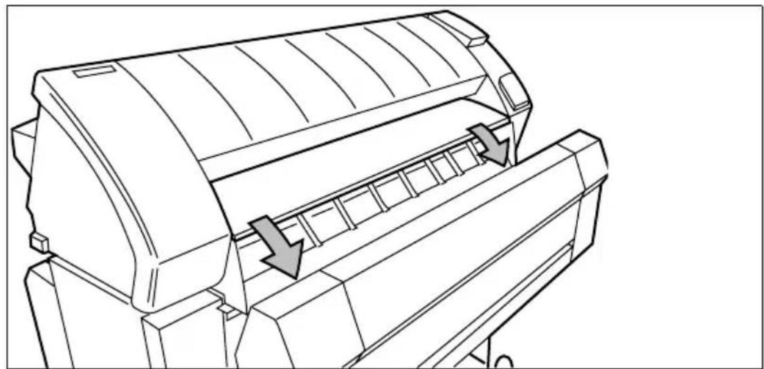
natural_image
Line drawing of a printer with arrows indicating process flow (no text or symbols)[34] Lowering the feed table
4 Remove the jammed material.
Note: Check thoroughly that no scraps of material are left behind.
5 Close the feed table.
6 Close the upper drawer.
7 Switch on the printer.
If the paper jam can not be cleared by opening the feed table than open the fusing section.
Clearing the paper jam in the fuser section
1 Switch off the printer.
2 Unscrew the knurled nut at the left hand side of the machine and open the cover (see figure 35).
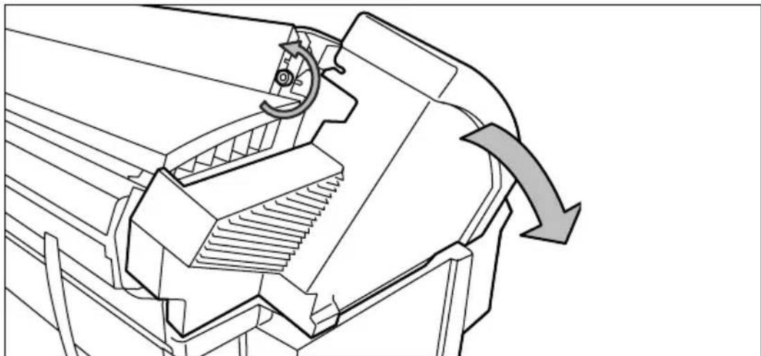
natural_image
Technical line drawing of a mechanical component with a curved arrow indicating rotation or motion (no text or symbols)[35] Unscrewing the knurled nut and opening the cover
3 Lift the green handle (see figure 4).
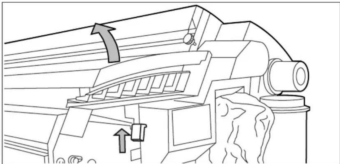
natural_image
Technical line drawing of a mechanical device with directional arrows indicating motion or flow (no text or symbols present)[36] Lifting the green handle
4 Open the fuser unit (see figure 37).
Caution: If the printer has been used recently, the fuser may still be hot.

natural_image
Technical line drawing of a mechanical assembly with grid and rod components (no text or symbols)[37] Opening the fuser unit
5 Remove the jammed material.
Attention: Be careful! The toner is not fused.
6 Lift the green handle and close the fuser unit.
7 Close the left cover and screw the knurled nut.
8 Switch on the printer.
Printer recoverable errors
In case of a printer recoverable error, a message with a 4-digit error code appears in the display.
Solving a printer error
1 Switch off the printer and check the complete paper path refer to ‘Clearing paper jams’ on page 122.
2 Then switch the printer on again. If no error number is shown in the display, you can continue printing.
If the printer error maintains, then call the key operator.
Problem solving copier
When an error occurs, the scanner operating panel informs you about the nature of the problem.
- if the printer error indicator is on, a jam has occurred in the printer (see ‘Problem solving printer’ on page 120) on how to solve the problem.
- if the display shows an error code letter E followed by an error code number, an original jam has occurred in the scanner (see ‘Clearing original jam’ on page 126)
- if the display shows a flashing 3-digit error code, a machine error has occurred in the scanner (see ‘Operator recoverable errors scanner’ on page 126).
Scanner error
When the scanner detects an error, the machine stops immediately. A flashing error code will be displayed on the scanner operating panel.
▼ Solving a scanner error
1 Switch off the scanner.
2 Then switch it on again.
If no error number is shown on the display, you can continue scanning.
Operator recoverable errors scanner
Message Description
| E1 | Original in scanner when switching on the scanner |
| E2 | Original too long |
| E3 | Stop/Correction button pressed during original transport |
Please wait
If the user wants to scan, but the printer is busy with printing files or a copy job, the please wait indication will light. If the printer is ready the indication goes out. The scanning will start.
Printer error
If the printer detects an error, the printer error indication will light. If the error is solved the indication goes out. Scanning can be started.
If during scanning a printer error occurs: the original will be fed in, and the scanning procedure will be finished. No copy will be made..
Clearing original jam
When the scanner detects an error, the machine stops immediately. A flashing error code will be displayed on the scanner operating panel. This code consists of a letter E followed by an error code number. The user has to take action to solve the problem.
▼ Clearing an original jam
1 Unlock the top cover by pushing the front side of the cover down and pulling it towards.
2 Raise the cover (see figure 38).

natural_image
Line drawing of a mechanical device with slots and brackets (no text or symbols)[38] Opening the top cover of the scanner
3 Remove the original.
4 Lower the top cover.
5 Lock the cover by pushing the front side of the cover down and pushing it back to the rear until you hear a click.
Note: Make sure that the cover is closed correctly, to ensure proper original transport.
6 Press the 'stop/correction' button. The error message will disappear on the panel.
Cleaning the glass platen
If the glass platen is dirty or static it should be cleaned to ensure top quality copies. At the same time you can clean the white pressure platen
Attention: To achieve the best results, we recommend the use of Océ cleaner 'A'. (Codenr. 1068117; Cleaner kit).
▼ Cleaning the glass platen and the pressure platen
1 Switch off the scanner.
2 Unlock the top cover by pushing the front side of the cover down and pulling it towards.
3 Raise the cover (see figure 38).
4 Clean the glass platen and the white pressure platen gently with a soft cloth moistened with a small quantity “Cleaner A” (see figure 39). For safety information see the safety data sheet in Appendix B.

natural_image
Line drawing of a printer or scanner with directional arrows indicating flow or movement (no text or symbols)[39] Cleaning the glass and the pressure platen
5 Lower the top cover.
6 Lock the cover by pushing the fornt side of the cover down and pushing it back to the rear until you hear a click.
Note: Make sure that the cover is closed correctly, to ensure proper original transport.
7 Switch on the scanner.
Appendix A Overview and tables

Product specifications printer
The Océ 9400 is a wide format low to mid volume copying and printing system.
Printer
| Technology | electrophotography (LED head) |
| Photoconductive drum | organic photoconductor (OPC) |
| Printing speed | 3m/min |
| Warm up time | none |
| Media feed | manual and 1- or 2 roll automatic |
| Toner system | closed |
| Maximum printable area | max. printable area depends on size of installed memory and file complexity, but possible up to 15 metres |
| Poster mode | increases the density of the copy |
Controller
| Standard memory | 32 MB |
| Vector data formats | HP-GL, HP-GL/2, CalComp 906/907, VDF, BGL, Edmics |
| Raster data formatas | HP-RTL, Cals type 1, TIFF 6.0 G3 & G4, NIRS, C4-G4 |
| Language sensing | automatic and via display panel |
| Multicopy | up to 99 |
| Interfacing | automatic switching:RS-232 serialCentronics parallelEthernet (optional) |
■ Optionals
| Automatic 2 roll-unit |
| Dew preventer |
| Memory upgrade to 48 or 64 Mb |
| PostScript level 2 |
| Scan to file |
| Ethernet interface |
| High capacity delivery tray |
| Compact Output Stacker |
Product specifications scanner
Scanner
| Free-standing unit | can only be used in combination with printer engine |
| Digital retention | up to 19 copies from one scan |
| Digital zoom | 25-400% in fixed steps or 1% increments |
| Paper selection | Roll1, Roll2 or Manual feed |
| Automatic Background Compensation | standard on but can be switched off |
| Leading/trailing edge correction | +80 ..... -80 mm in steps of 5 mm +3......-3” in steps of 0.25” |
| Invert copy | used to copy blue-prints (limited to single copy only and without ABC) |
| Poster mode | increases the density of the copy |
Interfaces
Centronics protocol
Centronics uses hardware handshaking. The computer sends a STROBE signal to move each byte of data into the printer, at which time the printer signals BUSY. When the transfer is complete, the printer sends ACKNOWLEDGE to the computer and another cycle can begin.
Serial protocols
Two types of computer-to-printer handshaking (and their variants) are available on the Océ 9400 printer:
- Hardware
- XON/XOFF
According to the selected emulation, handshake protocols can be set either through the software or the control panel.
When invoking a handshake protocol manually, the printer offers you the following character transmission handshaking selection:
■ CTS2 for hardware handshaking
■ XON4 for XON/OFF software handshaking
Your host or software documentation should tell you which handshaking is needed.
- XON4: The printer sends XON when its buffer has enough memory to receive character data. It sends an XOFF character to the computer when its buffer is almost full, indicating that the computer should stop sending characters.
- CTS2: Whenever the printer's buffer has enough memory to accept characters, it activates the CTS signal. It then de-activates the signal when the buffer is full.
Note: Hardware handshaking is enabled using the HP-GL ESC.P3 instruction. Xon/Xoff handshaking is enabled via the software using the ESC.P1 HP-GL instruction.
SCSI protocol
When the printer is attached to a SCSI-bus, it behaves itself as a standard SCSI tape device. SCSI tape commands are used to address the Océ 9400 for upload.
Ethernet protocol
When the printer is equipped with an Ethernet interface you can connect the printer to:
- TCP/IP
■ IPX (Novell netware) - Ethertalk network.
■ NETBIOS (over TCP/IP).
For more details refer to the Ethernet print server user manual.
Centronics port configuration
The Centronics parallel port is located at the rear of the printer. It is a mini Amphenol 36 pin female connector.
The following table describes the Centronics port pin assignment. For further details, refer to the IEEE P1284 standard.
Printer Pin No. Signal direction Name of the signal
| 1 | Printer to host BSY Busy |
| 2 | Printer to host SELECT Select |
| 3 | Printer to host ACKN Acknowledge |
| 4 | Printer to host FAULTN Fault |
| 5 | Printer to host PAPEROUT Paper error |
| 6 | Host to printer Data 1 Data 1 (LSB) |
| 7 | Host to printer Data 2 Data 2 |
| 8 | Host to printer Data 3 Data3 |
| 9 | Host to printer Data 4 Data 4 |
| 10 | Host to printer Data 5 Data 5 |
| 11 | Host to printer Data 6 Data 6 |
| 12 | Host to printer Data 7 Data 7 |
| 13 | Host to printer Data 8 Data 8 (MSB) |
| 14 | Host to printer INITN Initialize |
| 15 | Host to printer STROBEN Strobe |
| 16 | Host to printer SELECTINN Select in |
| 17 | Host to printer AUTOFDN |
| 18 | Host to printer Host Logic High |
| 19-35 | ---- GND Ground |
| 36 | Printer to host Peripheral Logic High |
STROBE is the dialog signal.

natural_image
Line drawing of a D-sub connector with port and mounting holes (no text or symbols)[40] Centronics connector
Serial port configuration
The RS-232/423-C serial port is located at the rear of the printer. It is a mini DIN 8 pin female connector (for printer in DCE - Data Communications Equipment). However it accepts DTE (Data Terminal Equipment) signals when DTE is selected under the PORT submenu of the Connections Menu.
The RS-423-C norm is an improved version of the RS-232-C serial connection.
The following table describes the serial port pin assignment.
Printer Pin No. Signal direction Name of the signal
| 1 | Host to printer DTR Data terminal ready |
| 2 | printer to host CTS Clear to send |
| 3 | Host to printer TX Transmit data |
| 4 | ---- GND Protective ground |
| 5 | Printer to host RX Received print data |
| 6 | Host to printer RTS Ready to send |
| 8 | Printer to host DSR Data set reday |
DTR is the dialog signal.

[41] Serial connector
SCSI port configuration
The SCSI connector is located on the optional SCSI-board at the rear of the printer. it is a mini Subd 50 pin female connector.
The following table describes the SCSI port pin assignment. For further details, refer to the ANSI X3.131 standard.
Printer Pin No. Name of the signal
| 1 | GND |
| 2 | GND |
| 3 | GND |
| 4 | GND |
| 5 | GND |
| 6 | GND |
| 7 | GND |
| 8 | GND |
| 9 | GND |
| 10 | GND |
| 11 | GND |
| 12 | GND |
| 13 | GND |
| 14 | GND |
| 15 | GND |
| 16 | GND |
| 17 | GND |
| 18 | GND |
| 19 | GND |
| 20 | GND |
| 21 | GND |
| 22 | GND |
| 23 | GND |
| 24 | GND |
| 25 | GND |
| 26 | SD10_N |
| 27 | SD10_N |
| 28 | SD10_N |
| 29 | SD10_N |
| 30 | SD10_N |
| 31 | SD10_N |
Printer Pin No. Name of the signal
| 32 | SD10_N |
| 33 | SD10_N |
| 34 | SD10_N |
| 35 | GND |
| 36 | GND |
| 37 | GND |
| 38 | TERM_PWR |
| 39 | GND |
| 40 | GND |
| 41 | ATNO_N |
| 42 | GND |
| 43 | BSYO_N |
| 44 | ACKO_N |
| 45 | SELI_N |
| 46 | MSGO_N |
| 47 | SELO_N |
| 48 | CDO_N |
| 49 | REQO_N |
| 50 | IOO_N |

natural_image
Diagram of a dual D-sub connector with pin layout (no text or labels)[42] SCSI connector
Originals that can be used
Overview of originals
Originals Minimum Maximum recommended
| Width 210 mm(8.5") | 1020 mm (40") of which image width 914 mm(36") can be copied without loss of information |
| Length 210 mm(8.5") | Guaranteed copy quality 3 meters or 10 feet.Maximum length limited by the worst-case speed difference between scanner and printer; at least >6m. |
Points of notice with regard to originals to be processed
| Curls | Originals with a curl diameter > 75mm, can easily be scanned. If the diameter of the curl is < 75 mm with help from the operator, it is advisable to uncurl the leading edge to prevent problems. Originals with a curl diameter < 50 mm, a carrier sheet may be used (not thicker than 0.3 mm) Dog-ears should be straightened out, especially on originals with reinforcement borders. |
| Damaged origi-nals | Torn originals should be repaired with tape. Badly damaged originals can be copied by inserting them into carrier sheets. |
| Miscellaneous | The leading edge of the original must be straight. The thickness of the original may be maximal 1.5 mm. Filing strips with a thickness 3 mm. Any paper clips, staples etc. should be removed from the original before feeding it into the scanner. Creased leading edges and traling edges should be straightened out. Paste-ups should be taped down 100 % at all edge; a carrier sheet may be used (not thicker than 0.3 mm) Folded originals should be straightened out before feeding. Wrinkles and folds may be visible on the copy. Feed plotter originals in carrier sheets. |
Copy material that can be used
Océ machines and materials are matched for optimal quality and performance. It is therefore recommended to use only approved Océ materials in the Océ 9400.
A full list of Océ materials suited for use in the Océ 9400, including plain paper, transparent paper, coloured papers and various polyester films is available from your Océ representative.
The maximum length of the print material is 150 m when you use 75 g/m^2 material and 140 m in case of 110 g/m^2 . The diameter of the roll holder equals 3 inch.
Paper formats Width
| A0 | 841 mm |
| A1 | 594 mm |
| A2 | 420 mm |
| A3 | 297 mm |
| E | 34” |
| D | 22” |
| C | 17” |
| B | 11” |
| E+ | 36” |
| D+ | 24” |
| C+ | 18” |
| B+ | 12” |
| 30” | 30” |
| 500 mm | 500 mm |
| 700 mm | 700 mm |
| B1 | 707 mm |
Overview of copy material
Copy material Recommended
Plain paper 75 g/m ^2
Transparent paper 110 g/m
Vellum 20 lbs
Polyester film 3.5 mil
ECO papers 75 g/m ^2
Minimum Maximum
Width 279 mm
914 mm
(11")
(36")
Length 420 mm
(A3)
Guaranteed print quality ca. 3 meter or 10 feet. This is also the limit for prints and multiple copies made on the Océ 9400.
For single copies/prints made on the Océ 9400 printer or hybrid, the maximum length may be up to 15 meter, but the operator has to accept that the copy/print quality may not conform to all quality aspects.
Attention: Paper and transparent materials are sensitive to high humidity. To ensure optimal copy quality, it is advisable (especially overnight) to keep all copy materials in their original packaging.
Attention: If sheets of print material are curled, feed them in with the curl facing down, otherwise you will damage the drum.
Overview of standard zoom formats
Standard zoom fixed steps ISO
| Original | Copy |
| A0 A1 A2 A3 A4 | |
| A0 | 100 71 50 35 25 |
| A1 | 141 100 71 50 35 |
| A2 | 200 141 100 71 50 |
| A3 | 283 200 141 100 71 |
| A4 | 400 283 200 141 100 |
Standard zoom fixed steps ANSI
| Original | Copy34 22 17 11 8 | ^1/_2 |
| 34 | 100 65 50 32 25 | |
| 22 | 100 50 | |
| 17 | 200 129 100 65 50 | |
| 11 | 200 100 | |
| 8^1/_2 | 400 259 200 129 100 |
Standard zoom fixed steps Architectural
| Original | Copy |
| 36 24 18 12 9 | |
| 36 | 100 67 50 33 25 |
| 24 | 100 50 |
| 18 | 200 133 100 87 50 |
| 12 | 200 100 |
| 9 | 400 267 200 133 100 |
Order of standard sizes for using standard cut
ISO ANSI ARCH
| A0 (841x1189 mm) 34” (34x44”) 36” (36x48”) | |||
| A1 (594x841 mm) 22” (22x34”) 24” (24x36”) | |||
| A2 (420x594 mm) 17” (17x22”) 18” 18x24”) | |||
| A3 (297x420 mm) 11” (11x17”) 12” (12x18”) | |||
| 34” (34x44”) 36” (36x48”) 34” (34x44”) | |||
| 22” (22x34”) 24” (24x36”) 22” (22x34”) | |||
| 17” (17x22” 18” (18x24”) 17” (17x22”) | |||
| 11” (11x17”) 12” (12x18”) 11” (11x17” | |||
| 36” (36x48”) 30” (30x42”) 30” (30x42”) | |||
| 24” (24x36”) | A0 (841x1189 mm) | A0 (841x1189 mm) | |
| 18” (18x24”) | A1 (594x841 mm) | A1 (594x841 mm) | |
| 12” (12x18”) | A2 (420x594 mm) | A2 (420x594 mm) | |
| 30” (30x42”) A3 (297x420 mm) A3 (297x420 mm) | |||
| 500 mm(500x707 mm) | 500 mm(500x707 mm) | 500 mm(500x707 mm) | |
| 700 mm (700x1000 mm) | 700 mm(700x1000 mm) | 700 mm(700x1000 mm) | |
| B1 (707x1000 mm) | B1 (707x1000 mm) | B1 (707x1000 mm) | |
Note: This table represents the order of standard sizes displayed on the scanner when using standard cut. The order depends on the setting which is set on the printer operating panel refer to ‘The printer operating panel’ on page 11.
Appendix B Safety information

Instructions for safe use
Océ machines and materials have been developed and tested in accordance with the strictest international safety standards. To ensure safe working with these products it is important that you observe the following safety rules:
- Do not remove any screws from fixed panels.
- The machine is not user-serviceable except for the components and maintenance materials mentioned in this manual.
■ Do not place any liquids on the machine. - Use maintenance materials or other materials for their original purpose only. Keep maintenance materials away from children.
■ Do not mix cleaning fluids or other materials. - To avoid risks, all modifications to Océ equipment are strictly reserved for Océ service personnel. It is recommended to use attachment cables specified by Océ.
■ The printer has been fitted with an ozone filter. - Do not bridge any mechanical or electrical circuit breakers.
- Do not use an extension lead to connect the machine.
- Locate the machine close to a wall socket that is easily accessible.
- The switch in the fixed connection (if any) should be easily accessible.
- This machine has not been designed for connection to an IT power system. (An IT power system is a voltage network in which the neutral wire is not connected to earth).
- Do not block the ventilation openings of the machine.
- Ensure that the machine is placed on a level, horizontal surface of sufficient strength. See the Océ 9400 safety data sheet in this appendix for information about the weight of the machine.
- Ensure there is sufficient space around the machine. This facilitates reloading materials as well as maintenance.
- Do not place the machine in rooms which are subject to excessive vibration.
- Do not place the machine in rooms which are too small and insufficiently ventilated. See the Océ 9400 safety data sheet in this appendix for information about space and ventilation requirements.
- Always use materials recommended by Océ and developed for this Océ machine. Materials not approved by Océ may result in faults in your machine.
- Do not use the machine when it is emitting unusual sounds. Remove the plug from the power socket and contact Océ Customer Service.
Safety data sheets
Disclaimer The disclaimer below is valid for all safety data sheets in this manual.
These safety data sheets have been compiled to the best of our knowledge as a compact guide to safe handling of this product. We reserve the right to revise safety data sheets as new information becomes available. It is the user's responsibility to determine the suitability of this information for the adoption of safety precautions as may be necessary and to contact the company to make sure that the sheet is the latest one issued. If and in so far as limitation of liability is permitted under the applicable laws we do not accept liability for any inaccuracy that may occur in this information.
Safety data sheet Océ 9400 printer

Number: E-661-b-UK
Date: April 1996
| Model Océ 9400 Printer | ||
| Description Plain paper printing machine, console model | ||
| Max. process speed 3 m/min | ||
| Dimensions WidthDepth 918 mm 918 mmHeightWeight | 1 roll 2 roll1352 mm 1352 mm1251 mm 1251 mm149 kg 159 kg | |
| VoltageFrequencyCurrent-ratedCurrent-maxPower consumption, operationPower consumption, standbyMains connectionSafety classProtection class | 230 V 230 V50 Hz 60 Hz7,5 A 7,5 A10 A 10 A1500 W39 WCable with plugI (IEC 536) Protective earth connectionIP 20 (IEC 529) | |
| Sound pressure levelSound power levelRadio InterferenceRadiationHeat emissionOzone emission | At operator position: in operation 51 dB(A); impulse Δ Li=2 dB(A)In operation 61 dB(A)Complies with Directive 89/336/EECBelow the Threshold Limit V alue for UV radiation (TL V list of ACGIH)Standby 39 W ; in operation 1500 W0,02 mg/min at continuous operation | |
| Room volumeRoom ventilationUse simulation at randomoperation | Recommendation: min. 25 m3Recommendation: min. 12,5 m3/h (natural ventilation)Room volume and ventilation as recommendedDaily copy volume (much more than average ) 100 mTotal worktime 8 hOzone concentrations:- Time weighted average 0,002 mg/m3- Peak 0,008 mg/m3Threshold Limit V alue/Occupational Exposure Limit(Time Weighted A verage) for ozone 0,2 mg/m3Odour Perception Limit for ozone 0,04 mg/m3(0,02 ppm) | |
| Consumables | Océ OPC Drum (Océ Safety Data Sheet E-175)Océ 9400 T oner (Océ Safety Data Sheet E-176)Océ 9400 Developer (Océ Safety Data Sheet E-177)Océ Copying Materials | |
| Marking | CE-Compliance Approved according toLow Voltage Directive 73/23/EEC   Approved according to EMC Directive 89/336/EEC Approved according to EMC Directive 89/336/EEC | |
| Additional safety information | The ozone filter does not have to be replaced for keeping the ozone concentration in the workplace below 0,04 mg/m3(the life of the filter equals that of the copier) | |
©1996 Océ-Technologies B.V.
The contents of this safety data sheet is subject to the disclaimer on page 147 of this manual.
Safety data sheet Océ 9400 scanner

Number: E-622-b-UK Date: April 1996
| Model Océ 9400 Scanner | |
| Description Freestanding scanner, maximum original size 1020mm * 3000mmMax. process speed 3m/min | |
| Dimensions Width 1240 mmDepth 615 mmHeight 1105 mmWeight 60 kg | |
| Voltage 230 VFrequency 50-60 HzCurrent-rated 0,7 ACurrent-max 1 APCow power consumption, operation 90 WPower consumption, standby 4 WCable with plugMalns connectionSafety class I (IEC 536) Protective earth connectionProtection class IP 20 (IEC 529) | |
| Sound pressure level Standby: In operation:0 dB(A) mainbody 48 dB(A);Sound power level Impulse Δ Li=5 dB(A)0 dB(A) mainbody 60 dB(A);Radio interference Complies with Directive 89/336/EECRadiation Below the Threshold Limit Value for UV radiation (TL V list of ACGIH)Heat emission Standby 4 W ; In operation 90 WOzone emission Not applicable | |
| Room volume Room ventilation | No special requirements |
| Consumables | Not applicable |
| Marking | CE-Compliance Approved according to Low Voltage Directive 73/23/EEC Approved according to EMC Directive 89/336/EECCE GS TUV TUV |
| Additional safety information | None |
©1996 Océ-Technologies B.V.
The contents of this safety data sheet is subject to the disclaimer on page 147 of this manual.
Safety data sheet Océ 9400 toner
MATERIAL SAFETY DATA SHEET Number E-176-a-UK
(91/155/EEC and ISO 11014) Date July 1995
Page 1 of 2

Océ 9400 Toner
1. Product and company identification
Product name Océ 9400 Toner
Packing Polyethylene bottle, contents 0.45 kg/1.1 lb
- Composition / information on ingredients
| Ingredients | CAS No. | Classification | Weight % |
| Polyester resin | 25-50 | ||
| Phenoxy resin | 25-50 | ||
| Magnetite (iron oxide) | 1309-38-2 | 10-25 | |
| Carbon black | 1333-86-4 | 1-5 | |
| Amorphous Silica | 68611-44-9 | <1 | |
| Pigment | <1 |
3. Hazards identification
In a toner dust cloud the formation of an explosive dust-air mixture is possible.
Toner dust may cause discomfort for the eyes and respiratory tract, in the same manner as inert nuisance dust.
To our knowledge, with due observance of the recommended exposure limit and of normal hygiene this product presents no health hazard in normal use.
4. First aid measures
Eyes contact Rinse with plenty of water.
Skin contact Wash with cold water and soap.
Inhalation Clean nose, mouth, throat. Cough up. Fresh air.
Ingestion Rinse mouth with water. If large quantity swallowed seek medical advice.
For any medical advice take along this material safety data sheet.
5. Fire fighting measures
Flash point (°C) N.A. (=Not Applicable)
Explosion limits (dust explosion)
Ignition temperature (°C)
Extinguishing media
Special fire fighting precautions
Hazardous products of decomposition N.A.
LEL approx. 60 g/m³. UEL U (= unknown)
Approx. 500
Dry chemical, carbon dioxide, water spray (fog), foam
N.A.
6. Accidental release measures
Spills can be cleaned with a vacuum cleaner or a damp rag. Do not use warm water, because this makes the powder soft and sticky.
7. Handling and storage
Keep bottle tightly closed to prevent dust formation. Handle carefully. Avoid breathing dust.
No special technical measures for storage.
8. Exposure controls / personal protection
No special technical measures. No personal protective equipment needed.
Industrial hygiene: after skin contact wash with cold water and soap.
Threshold Limit Value for:
* nuisance dust
* carbon black
* amorphous silica
10 mg/m ^3
3.5 mg/m³
10 mg/m ^3
continued on next page
MATERIAL SAFETY DATA SHEET Number E-176-a-UK
(91/155/EEC and ISO 11014) Date July 1995
Page 2 of 2

Océ 9400 Toner
- Physical and chemical properties
| Appearance and odour Black powder, faint odour. | |||
| Boiling point (°C) N.A Bulk density (kg/m3) Approx. 1400 | |||
| Vapour density (air = 1) | N.A. | Softening point (°C) | Approx. 60 |
| Solubility in water | Insoluble | Evaporation rate (butyl acetate = 1) | N.A. |
| Vapour pressure | N.A. | % Volatile | 0 |
| Other characteristics | N.A. | pH (solution) | N.A. |
- Stability and reactivity
| Thermal decomposition | Above approx. 450°C |
| Hazardous decomposition products | None at intended use |
| Hazardous reaction | None at intended use |
- Toxicological information
| Inhalation | ^A At high concentration in air the powder may cause discomfort of upper respiratory system. |
| Skin | ^* No adverse health effects are expected. |
| Eyes | ^* Dust may cause discomfort in the same manner as nuisance dust. |
| Ingestion | ^A Considered relatively harmless. |
| Mutagenicity | No mutagenicity detected in Ames test of similar toners. None of the ingredients is listed as mutagenic or carcinogenic. |
| ^* These statements are based on toxicological literature on the ingredients of this product and test results products. |
12. Ecological information
This product is not biodegradable. The ingredients are not classified as ecologically hazardous. No adverse environmental effects are expected.
13. Disposal considerations
Pack waste dustproof to prevent dusting. With due observance of local laws and regulations, dispose of by burial in a sanitary landfill or incineration. Do not throw in open fire, in order to prevent the risk of a dust explosion.
14. Transport information
This product is not classified as a dangerous substance according to the international transport regulations.
15. Regulatory information
This product is not classified as a dangerous preparation according to the European Directives 67/548/EEC and 88/379/EEC for the classification, packaging and labelling of dangerous substances and preparations.
16. Other information
Use: ink powder for printers. Room ventilation: see operator manual or safety data sheet for the machine.
©1996 Océ-Technologies B.V.
The contents of this safety data sheet is subject to the disclaimer on page 147 of this manual.
Safety data sheet Océ 9400 developer
MATERIAL SAFETY DATA SHEET
(91/155/EEC and ISO 11014) Date July 1995
Océ 9400 Developer
Number E-177-a-UK
Page 1 of 2

1. Product and company identification
Product name Océ 9400 Developer
Packing Polyethylene bottle, contents 1,75 kg/3.86 lb
- Composition / Information on Ingredients
| Ingredients | CAS No. | Classification | Weight % |
| Magnetite (iron oxide) | 1317-61-9 | 50-100 | |
| Polyester resin | 1-5 | ||
| Phenoxy resin | 1-5 | ||
| Carbon black | 1333-86-4 | < 1 | |
| Amorphous Silica | 68611-44-9 | < 1 | |
| Pigments | < 1 |
3. Hazards identification
In a developer dust cloud the formation of an explosive dust-air mixture is possible.
Developer dust may cause discomfort for the eyes and respiratory tract, in the same manner as inert nuisance dust.
To our knowledge, with due observance of the recommended exposure limit and of normal hygiene this product presents no health hazard in normal use.
4. First aid measures
Eyes contact Rinse with plenty of water.
Skin contact Wash with cold water and soap.
Inhalation Clean nose, mouth, throat. Cough up. Fresh air.
Ingestion Rinse mouth with water. If large quantity swallowed seek medical advice.
For any medical advice take along this material safety data sheet.
5. Fire fighting measures
Flash point (°C) N.A. (=Not Applicable)
Explosion limits (dust explosion) LEL U (= unknown)UEL U
Ignition temperature (°C) Approx. 500
Extinguishing media Dry chemical, carbon dioxide, water spray (fog), foam
Special fire fighting precautions N.A.
Hazardous products of decomposition N.A.
6. Accidental release measures
Spills can be cleaned with a vacuum cleaner or a damp rag. Do not use warm water, because this makes the powder soft and sticky.
7. Handling and storage
Keep bottle tightly closed to prevent dust formation. Handle carefully. Avoid breathing dust.
No special technical measures for storage.
8. Exposure controls / personal protection
No special technical measures. No personal protective equipment needed.
Industrial hygiene: after skin contact wash with cold water and soap.
Threshold Limit Value for:
^* nuisance dust 10 mg/m ^3
* carbon black 3,5 mg/m³
* amorphous silica 10 mg/m³
continued on next page
MATERIAL SAFETY DATA SHEET Number E-177-a-UK
(91/155/EEC and ISO 11014) Date July 1995
Page 2 of 2

Océ 9400 Developer
- Physical and chemical properties
| Appearance and odour Black powder, faint odour. | |||
| Boiling point (°C) N.A Bulk density (kg/m) | 3) Approx. 2500 | ||
| Vapour density (air = 1) | N.A. | Softening point (°C) | Approx. 60 |
| Solubility in water | Insoluble | Evaporation rate (butyl acetate = 1) | N.A. |
| Vapour pressure | N.A. | % Volatile | 0 |
| Other characteristics | N.A. | pH (solution) | N.A. |
- Stability and reactivity
| Thermal decomposition | Above approx. 450 ^ C |
| Hazardous decomposition products | None at intended use |
| Hazardous reaction | None at intended use |
- Toxicological information
| Inhalation | * At high concentration in air the powder may cause discomfort of upper respiratory system. |
| Skin | * No adverse health effects are expected. |
| Eyes | * Dust may cause discomfort in the same manner as nuisance dust. |
| Ingestion | * Considered relatively harmless. |
| Mutagenicity | None of the ingredients is listed as mutagenic or carcinogenic. |
| * These statements are based on toxicological literature on the ingredients of this product and test results of similar products. |
- Ecological information
| This product is not biodegradable. |
| The ingredients are not classified as ecologically hazardous. No adverse environmental effects are expected. |
- Disposal considerations
| Pack waste dustproof to prevent dusting. With due observance of local laws and regulations, dispose of by burial in a sanitary landfill or incineration. Do not throw in open fire, in order to prevent the risk of a dust explosion. |
- Transport information
| This product is not classified as a dangerous substance according to the international transport regulations. |
- Regulatory information
| This product is not classified as a dangerous preparation according to the European Directives 67/548/EEC and 88/379/EEC for the classification, packaging and labelling of dangerous substances and preparations. Therefore, indications of special risks or safety advice on the packing are not prescribed for this product. |
- Other information
| Use: ink powder for printers. |
| Room ventilation: see operator manual or safety data sheet for the machine. |
©1996 Océ-Technologies B.V.
The contents of this safety data sheet is subject to the disclaimer on page 147 of this manual.
Safety data sheet Océ 9400 OPC drum
MATERIAL SAFETY DATA SHEET Number E-175-a- UK
(91/155/EEC and ISO 11014) Date July 1996
Page 1 of 2

Océ OPC Drum, Part No. 2977053
1. Product and company identification
Product name Océ OPC Drum, Part No. 2977053 (for Océ 9400)
2. Composition / information on ingredients
| Ingredients | CAS No. | Classification | Weight % |
| Aluminium 7429-90-5 | >99 | ||
| Resins | < 1 | ||
| Pigments | < 1 |
3. Hazards Identification
To our knowledge this product presents no health hazard in normal use.
4. First aid measures
Eyes contact Not Applicable(=N.A.)
Skin contact N.A.
Inhalation N.A.
Ingestion N.A.
For any medical advice take along this material safety data sheet.
5. Fire fighting measures
| Flash point (°C) N.A. (=Not Applicable) | |
| Explosion limits (dust explosion) | LEL N.A. UEL N.A |
| Ignition temperature (°C) | N.A. |
| Extinguishing media | Dry chemical, carbon dioxide, water spray (fog), foam |
| Special fire fighting precautions | N.A. |
| Hazardous products of decomposition | N.A. |
6. Accidental release measures
N.A.
7. Handling and storage
No special technical measures for storage.
8. Exposure controls / personal protection
No special technical measures. No personal protective equipment needed.
No special work hygiene practices needed.
continued on next page
MATERIAL SAFETY DATA SHEET Number E-175-a-UK
(91/155/EEC and ISO 11014)
Date
July 1996
Page
2 of 2

Océ OPC Drum, Part No. 2977053
9. Physical and chemical properties
| Appearance and odour brown odourless drum | |||
| Bolling point (°C) N.A Density (g/cm | 3) 2,7 | ||
| Vapour density (alr = 1) N.A. Melting point ( | °C) N.A. | ||
| Solubility in water | Insoluble | Evaporation rate (butyl acetate =1) | N.A. |
| Vapour pressure | N.A. | % Volatile | 0 |
| Other characteristics | N.A. | pH (solution) | N.A. |
- Stability and reactivity
| Thermal decomposition | None at intended use |
| Hazardous decomposition products | None at intended use |
| Hazardous reaction | None at intended use |
- Toxicological information
| Inhalation | N.A. |
| Skin | No adverse health effects are expected. (Based on toxicological literature on the ingredients of this product) |
| Eyes | N.A. |
| Ingestion | N.A. |
| Mutagenicity | No mutagenicity detected in Ames test. None of the ingredients is listed as mutagenic or carcinogenic. |
- Ecological information
| This product is not biodegradable. |
| The ingredients are not classified as ecologically hazardous. No adverse environmental effects are expected. |
- Disposal considerations
| The drum will be returned to Océ for re-use. |
- Transport information
| This product is not classified as a dangerous substance according to the international transport regulations. |
- Regulatory information
| This product is an article and contains no dangerous substances. Therefore, indications of special risks or safety advice on the packing are not prescribed for this product. |
- Other information
| Use: photoconductor for copiers. |
©1996 Océ-Technologies B.V.
The contents of this safety data sheet is subject to the disclaimer on page 147 of this manual.
EPA ENERGY STAR®
Océ-Technologies B.V. has joined the ENERGY STAR ^® Program of the United States Environmental Protection Agency (EPA). The purpose of the ENERGY STAR ^® Program is to promote the manufacturing and marketing of energy-efficient equipment, thereby potentially reducing combustion-related pollution. Using the energy management features outlined below prevents unnecessary power consumption, which helps to prevent air pollution from electricity generating plants and saves money on your utility bills.
As an ENERGY STAR ^® Partner, Océ-Technologies B.V. has determined that this copier model meets the ENERGY STAR ^® guidelines for energy efficiency.
The EPA ENERGY STAR ^® Criteria for copiers involve the following features:
auto-off feature The use of the auto-off feature offers economic and environmental benefits. The copier is shipped with the auto-off default time set at 90 minutes, which means that the copier automatically switches itself off 90 minutes after the last copy is made ^1 . The auto-off default time can be adjusted by the key operator to between 2 and 240 minutes. It is suggested to determine the appropriate default time for your work pattern by changing the setting in steps of 30 minutes and testing each setting for at least a week. Only if an auto-off default time of 240 minutes still causes you sizeable inconvenience, due to your particular usage pattern, should you request the Océ service technician to disable the auto-off feature.
low power mode In the low power mode, the power consumption of certain functions is automatically reduced to save energy. The copier enters the low power mode 15 minutes after the last copy is made ^1 . This default time can be adjusted by the key operator to between 2 and 240 minutes. The low power mode recovery time is less than 3 seconds, after which copying can be resumed.
automatic duplex mode Using both sides of paper reduces paper costs, national energy consumption and the amount of paper in the waste disposal process. You are encouraged to duplex (make double-sided copies) as often as feasible or to choose double-sided copying as the default setting.
recycled copier paper The use of recycled paper also benefits the environment. This copier is designed to use recycled paper. Product literature on recommended types of recycled copier paper can be obtained from your local Océ company or Océ Headquarters (Océ-Technologies B.V.) in Venlo, the Netherlands.
^1 For power consumption data: see Product Safety Data Sheet in this appendix.

ENERGY STAR® is a U.S. registered mark.
Appendix C Miscellaneous

Notation conventions
There are a number of notation conventions used in this manual. This consistent style enables you to quickly become conversant with the use of this manual and consequently the Océ 9400.
Description Each section or subsection contains a description of the feature or operation identified in the title. It might also include possible applications, as well as any guidelines that you should bear in mind.
Procedures A description is followed by a procedure. A procedure always begins with a phrase which briefly describes the procedure, followed by a series of numbered steps that take you, step by step, through all phases of performing the operation.
Figures and tables Figures and tables are titled and numbered sequentially throughout this manual. Figures include pictures of product components, screendumps, examples, and diagrams of concepts discussed in the description.
Attention getters There are several types of information to which we draw your attention. This information is classified as follows:
Note: In a ‘Note’, information is given about matters which ensure the proper functioning of the machine or application, but useful advice concerning its operation may also be given.
Attention: The information that follows ‘Attention’ is given to prevent something (your copy or original, the copier or printer, data files etc.) being damaged.
Caution: The information that follows ‘Caution’ is given to prevent you suffering personal injury.
Reader's comment sheet
Have you found this manual to be accurate?
□ Yes
□ No
Could you operate the product after reading this manual?
□ Yes
□ No
Does this manual provide enough background information?
□ Yes
□ No
Is the format of this manual convenient in size, readability and arrangement (page layout, chapter order, etc.)?
□ Yes
□ No
Could you find the information you were looking for?
□ Always
□ Most of the times
□ Sometimes
□ Not at all
What did you use to find the required information?
□ Table of contents
Index
Are you satisfied with this manual?
□ Yes
□ No
Thank you for evaluating this manual.
If you have other comments or concerns, please explain or suggest improvements overleaf or on a separate sheet.
Comments:
Date:
This reader's comment sheet is completed by:
(If you prefer to remain unknown, please do fill in your occupation)
Name:
Occupation:
Company:
Phone:
Address:
City:
Country:
Please return this sheet to:
Océ-Technologies B.V.
For the attention of ITC User Documentation.
P.O. Box 101,
5900 MA Venlo
The Netherlands
Addresses of local Océ organisations
Océ-Australia Ltd.
P.O.Box 363
Ferntree Gully MDC VIC 3165
Australia
Océ-Österreich GmbH
Postfach 95
1233 Vienna
Austria
Océ-Belgium N.V./S.A.
Avenue J.Bordetlaan 32
1140 Brussels
Belgium
Océ Office Equipment (Beijing) Co Ltd.
Xu Mu Cheng
Chaoyang District
Beijing 100028
China
33 Hysan Avenue, Causeway Bay
Hong Kong
Océ-Hungária Kft.
P.O.B. 237
1241 Budapest
Hungary
Océ-Italia S.p.A.
Strada Padana Superiore 2/B
3.01, Level 3, Wisma Academy
Lot 4A, Jalan 19/1
46300 Petalig Jaya
Malaysia
Océ-Nederland B.V.
P.O.Box 800
5201 AV 's-Hertogenbosch
The Netherlands
Océ Norge A/S
Océ (Far East) Pte. Ltd./
Océ (Singapore) Pte. Ltd.,
03-00 Wisma Gulab
190 MacPherson Road
Singapore 348548
Océ España SA
Business Park MAS BLAU
C/Osona 2, 2-3a Planta
08820 El Prat del Llobregat (Barcelona)
Spain
Océ-Svenska AB
P.O.box 1231
S-164 28 Kista
Sweden
Océ-Schweiz AG
Sägereistrasse 29
CH8152 Glattbrugg
Switzerland
Océ (Taiwan) Ltd.
No. 99-24 Nan Kang Road Sec.2
Taipeh, Taiwan
Taiwan, RO
Océ (Thailand) Ltd.
16th Floor, B.B. Building
54 Asoke Road, Sukhumvit 21
Bangkok 10110
Thailand
Océ-U.K.Ltd.
Langston Road
Loughton, Essex IG10 3SL
United Kingdom
Océ-USA Inc.
5450 North Cumberland Av.
Chicago, Ill. 60656
U.S.A.
Index
A
auto roll selection 45, 46
automatic language sensing 79
automatic roll switch 47
autoposition 106
B
baud rate 25
bitmap buffer 32
bits combination 25
C
calcomp 91
centronics port 23
centronics protocol 132
checksum 91
cleaner a 128
cleaning
glass platen 127
pressure plate 127
compact output stacker 10, 130
connector
centronics 134, 135
scsi 137
serial 136
copy process
start 53
cut method
programming 67
cutting paper 40
D
demo print 69
designjet
compatibility 89
double synchronization 94
dump configuration 112
E
end of message 93
end of plot time out 102
end of print 102
ethernet interface 10
F
feeding the original 53
flush media saver 107
framing 26
full menus 117
G
glass platen 127
H
handshake protocol 24
high capacity deliver tray 10
|
image logic technology 52
input buffer 31
inter character delay 28
interfaces 132
L
language recognition 80
leading edge 68
programming 69
load
print material 36
locked menu 117
M
media saver 103
media saver plot size 108
media saver time out 107
menu levels 117
merge mode
calcomp 93
hp-gl 86
hp-gl/2 89
N
nesting 103
0
on/off switch printer 18
on/off switch scanner 18
operating panel 16
operating panel printer 11
operating panel scanner 15
origin 91
original guide 53
P
page advance
hp-g1 86
hp-gl/2 87
paper formats 140
paper jam 122
parity 26
pen priority
calcomp 92
hp-gl/2 88
océ 84
pen settings 77
plot center 68
port configuration
centronics 134
serial 136
port type 27
poster mode 64, 111
postscript
data format selection 98
manual data format selection 98
page layout 99
page size 99
postscript level 2 10
postscript option 98
pressure plate 127
print material 36
print origin
calcomp 91
hp-gl 85
hp-gl/2 87
océ 82
print settings 76
printmaterial 140
problems 120
product specifications 130
program
auto switch 47
automatic roll selection 46
default paper feed 46
media type 46
media width 46
R
refill toner 48
rendering 76
replot 109
rewind 54
rotation 113
S
safety data sheets 147
safety information 146
scaling 113
scan to file 72
scanner feed table 53
scsi connector 137
scsi port 29
serial connector 136
serial port 24
serial protocols 132
short menus 117
standard cut 52, 67, 68
standard cut mode 17
step size 96
calcomp 96
océ 83
stop bits 26
switching off
copier 18
printer 19
switching on
copier 18
printer 19
synchro cut 52, 67, 68
synchro cut mode 17
synchronization code 94
T
top cover 126, 127
trailing edge 68
programming 69
transmission speed 23
turnaround delay 27
U
upload 72
W
waste toner bag 50
- Overview of copier parts on the covers
- Safety information
- Trademarks
- Copyright
- Contents
- Chapter 1
- Getting started
- Chapter 2
- Installation of the printer
- Chapter 3
- (Re)load media and toner
- Chapter 4
- Copy jobs
- Chapter 5
- Print jobs
- Chapter 6
- Upload jobs
- Chapter 7
- Customizing the printer
- Chapter 8
- Advanced printer menu functions
- Chapter 9
- Solving problems
- Appendix A
- Overview and tables
- Appendix B
- Appendix C
- Miscellaneous
- Chapter 1 Getting started
- The Océ 9400 printer
- Optional:
- The printer operating panel
- Buttons
- Display
- The Océ 9400 copier
- The scanner operating panel
- Stand-by mode
- Buttons and functions
- Switching on/off the copier
- Switching on the scanner
- Switching off the scanner
- Switching on/off the printer
- Switching on the printer
- Switching off the printer
- Chapter 2 Installation of the printer
- Connect the printer to your host environment
- Centronics
- Connecting Centronics
- Defining transmission speed
- Serial
- Connecting serial
- Handshake protocol
- Defining handshake protocol
- Baud rates
- ▼ Defining the baud rate
- Bits combination
- ▼ Defining the bits combination
- Serial parity and stop bits
- Setting the parity and stop bits
- Port type
- ▼ Selecting the port type
- Turnaround delay
- Setting the turnaround delay
- Inter character delay
- Setting the inter character delay
- SCSI
- Connecting SCSI
- Defining the SCSI ID
- Setup the memory configuration
- Input buffer
- Setting the input buffer size
- ▼ Activating the new input buffer size
- Bitmap buffer
- Setting the bitmap buffer
- Activating the new bitmap buffer size
- Chapter 3 (Re)load media and toner
- Inserting a new print material roll
- Setting the media format
- Automatic roll switching
- Defining automatic roll switching
- Reloading rolls
- Reloading roll 1
- Cutting the paper to get a straight leading edge
- ▼ Cutting the paper from roll 1 or roll 2
- Reloading roll 2
- Printing using the manual feed
- Inserting print material in the manual feed
- Programming media settings
- Programming media width settings
- Programming media type settings
- Programming default paper feed
- Programming automatic roll selection
- Programming automatic switching
- Setting the time-out for manual feed
- Refilling toner
- Replacing the waste toner bag
- Chapter 4 Copy jobs
- Introduction
- Making copies
- Feeding the original
- Starting the copy process
- Activating/de-activating the rewind function
- ▼ De-activating the rewind function (in situation 3)
- Activating the rewind function (in situation 2)
- Change settings
- Number of copies
- ▼ Selecting the number of copies
- Copying using roll 1 or roll 2
- ▼ Selecting roll 1, roll 2 or manual feed
- Copying using manual feed
- ▼ Selecting manual feed
- Reduction/enlargement
- ▼ Making reduced/enlarged copies with pre-set zoom settings
- ▼ Making reduced/enlarged copies with 1% steps
- Copying using synchro or standard cut
- Selecting synchro or standard cut
- Adjusting the leading/trailing edge
- Leading edge
- Modifying the exposure
- ▼ Manually adjusting the exposure
- Inverted copies/Blueprints
- ▼ Making invert copies
- Poster mode
- ▼ Activating Poster mode
- ▼ De-activating the Poster mode
- Chapter 5 Print jobs
- Printing files
- Océ applications
- Océ drivers
- Cut method
- Programming cut method
- Plot Center
- Programming Plot Center
- Leading/trailing edge
- ▼ Programming leading or trailing edge
- Demo plot
- ▼ Making a demo plot
- Cancel plot
- ▼ Cancelling a plot
- Chapter 6 Upload jobs
- ▼ Making uploads
- Chapter 7 Customizing the printer
- Defining pen settings
- Defining the pen settings
- Defining rendering
- Defining language settings
- Automatic language sensing
- ▼ Activating ALS
- Data format recognition
- ▼ Optimizing data format recognition
- Manual data format selection
- Setting manual data format
- Océ languages (VDF/BGL)
- Océ print origin
- Defining the print origin
- Océ step size
- Defining the step size
- Océ pen priority
- ▼ Defining pen priority Océ setup
- HP-GL
- HP-GL print origin
- ▼ Defining the HP-GL print origin
- HP-GL page advance
- Setting the HP-GL page advance
- Merge mode
- Setting the merge mode
- HP-GL/2
- HP-GL/2 print origin
- ▼ Defining the HP-GL/2 print origin
- HP-GL/2 page advance
- Setting the HP-GL/2 page advance
- HP-GL/2 pen priority
- ▼ Defining pen priority HP-GL/2
- Designjet compatibility
- ▼ Defining Designjet compatibility
- HP-RTL
- CalComp
- CalComp print origin
- ▼ Defining the print origin
- Checksum parameter
- ▼ Defining the checksum parameter
- CalComp pen priority
- End of Message parameter
- Setting the End of Message parameter
- Synchronization code parameter
- Setting the synchronization code parameter
- Double synchronization code parameter
- Setting the double synchronization code parameter
- CalComp step size
- Setting the appropriate step size
- Raster formats
- CALS
- NIRS
- TIFF
- C4 (EDMICS)
- PostScript level 2
- PostScript data format selection
- PostScript page layout
- Selecting the PostScript page layout
- Default PostScript page size
- Selecting the default PostScript page size
- Chapter 8 Advanced printer menu functions
- End of plot time out
- Defining the end of plot time out
- Selecting the media saver
- Nesting
- ▼ Selecting nesting
- Autoposition
- Selecting autoposition
- Deselecting the media saver
- Media saver time out
- Setting the media saver time out
- Flush media saver
- Setting the flush media saver
- Media saver plot size
- Setting the media saver plot size
- Replot
- Enabling replot
- Setting the number of copies
- ▼ Defining the number of prints
- Enabling Poster mode
- Dump configuration
- Dumping the configuration
- Transformation
- Print rotation
- ▼ Defining the print rotation
- Print scaling
- ▼ Defining print scaling
- Autoscaling
- Fit to Format Mode:
- Best fit Mode:
- Defining autoscaling
- Setting the menu access level
- Service
- Chapter 9 Solving problems
- Problem solving printer
- Printer warnings
- Warnings Description
- Operator recoverable errors (printer)
- Clearing paper jams
- ▼ Clearing a paper jam in the material feed section
- Clearing the paper jam in the fuser section
- Printer recoverable errors
- Solving a printer error
- Problem solving copier
- Scanner error
- ▼ Solving a scanner error
- Operator recoverable errors scanner
- Message Description
- Please wait
- Printer error
- Clearing original jam
- ▼ Clearing an original jam
- Cleaning the glass platen
- ▼ Cleaning the glass platen and the pressure platen
- Appendix A Overview and tables
- Product specifications printer
- Printer
- Controller
- ■ Optionals
- Product specifications scanner
- Interfaces
- Centronics protocol
- Serial protocols
- SCSI protocol
- Ethernet protocol
- Centronics port configuration
- Serial port configuration
- SCSI port configuration
- Originals that can be used
- Overview of originals
- Points of notice with regard to originals to be processed
- Copy material that can be used
- Overview of copy material
- Minimum Maximum
- Overview of standard zoom formats
- Order of standard sizes for using standard cut
- Appendix B Safety information
- Instructions for safe use
- Safety data sheets
- Safety data sheet Océ 9400 printer
- ©1996 Océ-Technologies B.V.
- Safety data sheet Océ 9400 scanner
- Safety data sheet Océ 9400 toner
- MATERIAL SAFETY DATA SHEET Number E-176-a-UK
- Océ 9400 Toner
- Product and company identification
- Hazards identification
- First aid measures
- Fire fighting measures
- Accidental release measures
- Handling and storage
- Exposure controls / personal protection
- Ecological information
- Disposal considerations
- Transport information
- Regulatory information
- Other information
- Safety data sheet Océ 9400 developer
- MATERIAL SAFETY DATA SHEET
- Océ 9400 Developer
- MATERIAL SAFETY DATA SHEET Number E-177-a-UK
- Safety data sheet Océ 9400 OPC drum
- MATERIAL SAFETY DATA SHEET Number E-175-a- UK
- Océ OPC Drum, Part No. 2977053
- Composition / information on ingredients
- EPA ENERGY STAR®
- Appendix C Miscellaneous
- Notation conventions
- Reader's comment sheet
- Comments:
- Date:
- Name:
- Occupation:
- Company:
- Phone:
- Address:
- City:
- Country:
- Addresses of local Océ organisations
- 3.01, Level 3, Wisma Academy
- 03-00 Wisma Gulab
- Index
- A
- B
- C
- D
- E
- F
- G
- H
- |
- L
- M
- N
- 0
- P
- R
- S
- T
- U
- W
Brand : Océ
Model : 9400
Category : Printer