
X3 - Kitchen scale CASO - Free user manual and instructions
Find the device manual for free X3 CASO in PDF.


| Brand | CASO |
| Model | X3 |
| Product type | Digital kitchen scale |
| Maximum capacity | 5 kg |
| Precision | 1 g |
| Units of measurement | g, kg, lb, oz |
| Tare function | Yes |
| Display | LCD, backlit |
| Platform material | Stainless steel |
| Housing material | ABS plastic |
| Dimensions (L x W x H) | 20 x 15 x 2 cm |
| Weight | 300 g |
| Power supply | 2 AAA batteries (included) |
| Auto-off | Yes, after 2 minutes of inactivity |
| Overload indicator | Yes |
| Low battery indicator | Yes |
| Cleaning | Wipe with a damp cloth, do not immerse |
| Repairability | User-replaceable batteries |
| Safety | Do not use near water, do not expose to extreme temperatures |
| Warranty | 2 years |
Frequently Asked Questions - X3 CASO
User questions about X3 CASO
0 question about this device. Answer the ones you know or ask your own.
Ask a new question about this device
Download the instructions for your Kitchen scale in PDF format for free! Find your manual X3 - CASO and take your electronic device back in hand. On this page are published all the documents necessary for the use of your device. X3 by CASO.
USER MANUAL X3 CASO
natural_image
Exterior view of a Luxura water heater device (no signage or text visible on body)X _3
Owner's manual Anleitung Handleiding Mode d'emploi
This manual provides the required information on warnings, instructions and assembly. You should use this manual for more than just the necessary sunbed assembly and/or maintenance instructions; you need to familiarize yourself with all of the information provided. Persons who use the sunbeds need to be informed and supervised, and it is your duty to make sure they receive proper assistance.
Owner's manual ..... 4
Anleitung ..... 1 4
Handleiding. 24
Warranty policy ....5
Read this first 6
Golden rules for sensible tanning in the tanning unit....7
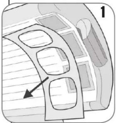
Removing the acryl sheets 8
Operating instructions....9
Information on lamps 10
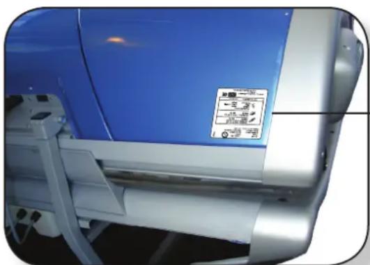
Information on the "permanent label" on the cubicle wall....11
Warning symbols....13
Tanning tables 44
Line-up / Dimensions 48
Technical data 49
Assembly tanning unit....50
Conversion tables 55
Spare parts list 62
Electrical diagrams. 64
Congratulations on the purchase of your Hapro sun bed. Your new sun bed has been manufactured with the utmost care and attention and consists of high-quality parts. All Hapro sun beds have been developed to give you the best possible tan, whilst complying with the strictest applicable European standards.
Warranty
Our tanning units are manufactured with the greatest attention and are of excellent quality.
Every Luxura is manufactured to meet the international IEC/EN standards and carries the Kema seal of approval. We provide a manufacturer's warranty of 1 year.
Your new sun bed has a manufacturer's guarantee of 1 year, which commences on the date of installation. Within the warranty period all faults that are the result of material or manufacturing errors will be repaired at no cost. Please contact your dealer for any warranty enquiries.
In order to make a claim under the terms of this guarantee, you must be able to produce the original invoice or receipt bearing the date of purchase. The type and serial number of the appliance should also be indicated.
The warranty is subordinate to the national regulations on product warranties.
Not covered under this warranty
Units which have the type, serial number and/or other identification labels removed, damaged or altered.
Lamps, starters and acrylic sheets.
Damage due to purchaser abuse, neglect, transport, improper use or improper maintenance.
Damage due to use of accessories not originally supplied by Hapro or inferior accessories.
Damage due to installation, repair or assembly not done by Hapro authorised personnel.
Damage due to fire, lightning, earthquakes or other natural disasters.
Note:
Please consult enclosed tanning schedule for advised tanning times.
Repairs may only be carried out by qualified personnel.
Always disconnect the main power at the circuit breaker before servicing or repairing the unit.
Read this first
Everything regarding assembly, instructions and other details contained in this manual must be followed correctly and entirely. Failure to do so correctly or entirely will render the right to any product warranty or liability on the supplier's behalf null and void. If there is any uncertainty as to whether the instructions contained in this manual have been followed properly and entirely, you should contact
the supplier of the sunbeds.
1 Contact your authorised Hapro dealer immediately if this unit does not function as outlined in this manual.
2 Do not operate this unit in humid spaces.
3 Always make sure the fuses can carry the load. This unit has to be protected by ground fault circuit interrupter (GFCI) of 0.03A.
4 Always disconnect the power to the unit at the wall breaker (isolator) when servicing or cleaning the in-side construction of the cabine. Maintenance for which the procedure is not described in this manual should only be carried out by a qualified electrician. Never clean the electrical components with fluids.
5 Ensure that the canopy does not touch the wall when opened.
6 Prevent the acrylic sheets from coming into contact with sharp objects.
7 This unit may not be operated if:
• the user is not wearing protective uv-goggles
• the blue or white facial glass is cracked or broken
• the acrylic panel in the canopy and/or bench is missing
- one or more of the fans in the unit are not functioning properly
• the timing mechanism is not functioning properly
• the temperature inside the cabin is 30^ C or higher
8 To ensure maximum tanning effectiveness, change the acrylic sheet after every 1200 hours of operation.
9 To ensure maximum tanning effectiveness, replace the lamps and the facial tanning lamps according to manufacturer's instructions.
10 Check local regulations to find out the proper procedure for lamp disposal.
11 Note: only a special acrylic cleaner may be used to clean the acrylic sheet. Never use cleaners that contain alcohol, as these can damage the acrylic sheet.
12 The UV-type of the tanning unit is indicated on the specification sticker.
13 Ultraviolet radiation from the sun or UV appliances can cause skin or eye damage. These biological effects depend upon the quality and quantity of the radiation as well as the skin and eye sensitivity of the individual.
14 Excessive exposure may cause skin to burn. Excessive repeated exposure to ultraviolet radiation from the sun or UV appliances may lead to premature ageing of the skin as well as increase risk of skin tumours.
15 The unprotected eye may develop surface inflammation and in some cases, after a cataract operation for example, damage may occur to the retina after excessive exposure. Cataracts may develop after prolonged exposures.
16 If the supply cord is damaged, it must be replaced by the manufacturer or service agent or a similarly qualified person in order to avoid a hazard.
17 To replace lamps and starters, remove by turning a quarter turn to the left. Placement of new lamps and starters is done in the reverse to the above mentioned procedure.
18 When installing the equipment, follow the recommended minimum distances listed in the "Dimensions / Placement" chapter.
19 Clean the dust filters after every 50 hours of use. Regularly check the dust filters.
20 Children should be supervised to ensure that they do not play with the tanning unit.
21 Non-users, especially children, must not be present when the appliance is being operated.
Note:
If your customers are using any medication, ask them to consult their doctor before starting a series of tanning sessions.
Golden rules for sensible tanning
These rules are in accordance with the European regulations concerning safe use of tanning equipment.
We advise you to inform your clients about these rules.
1 Before your client starts tanning, first thoroughly consult the tanning table included in this book and follow the recommendation given.
2 This sunbed is not suitable for use by:
• Persons with reduced sensory and/or mental capacity
- Persons lacking knowledge of or experience with sunbeds, with the exception of individuals who are being supervised or have received instructions regarding the use of the sunbed by a person who assumes responsibility for their safety.
3 Sunbeds are not suitable for use by:
- Persons whose skin is prone to burn without being exposed to sunlight
- Persons whose skin is already sunburned or has been burned in a tanning bed
• Persons who have been diagnosed with skin cancer or precursors of skin cancer - Persons without a medical advice who experience unexpected symptoms such as itching within 48 hours of using a sunbed for the first time.
- persons who tend to freckle
• persons with a natural red hair colour
• persons having abnormal discoloured patches on skin
- persons having more than 16 moles (2 mm or more) on the body
- persons having atypical moles (defined as asymmetrical moles larger than 5 mm in diameter with variable pigmentation and irregular borders: in case of doubt, seek medical advice)
- Seek medical advise if persistent lumps or sores appear on the skin or if there are changes in pigmented moles.
• persons with a family history of melanoma.
- persons under a doctor's care for diseases that involve photosensitivity and/or receiving photosensitising medications
- persons who burn easily when exposed to the sun, or having a history of frequent severe sunburn during childhood
- persons who are not able to tan at all or able to tan without burning when exposed to the sun
- Persons younger than 18
4 Make sure that upon commencing a series of tanning
sessions your customers have a rest day following their first tanning session. If there is no sign of any undesirable skin reaction they can then continue with the series of sessions.
5 Make sure that your customers do not tan more than once a day. This applies to tanning using an appliance and tanning in natural sunlight. The skin does not make a distinction between the two. Take exposure to natural sunlight into account.
6 Some medicines and beauty products contain substances which can cause certain undesirable reactions when combined with exposure to UV radiation. Other substances may also sometimes have a similar effect. Below you will find a list of substances which can react when combined with exposure to UV radiation:
- Sulphonamide - in various medications, including antibiotics
• Tetracyclines - in antibiotics and acne medication
• Nalidexine acid - in urinary tract infection medication
• Chlorothiazide - in diuretics
• Sulphonylurea · in diabetes medication
• Phenothiazines - anxiety medication
• Triacetyldiphenylisatine · in laxatives
• Psoralenes - in tanning accelerators
• Cyclamates - in sweeteners
- Para-aminobenzoic acid (PABA) - in sunscreen creams/oils
- Musk ambrette, musk oil - in perfumes
- Bleaching agents - in washing powders/liquids
- Eosine · in colourings
• Halogenated salicylamide - in antifungal substances
7 When combined with exposure to ultraviolet light, cosmetic products, e.g. perfumes and make-up can cause the skin to react. Ensure that your customers skin is clean before they start tanning. Some products penetrate deep into the skin. Advise your customers to make sure that their skin is clean during their tanning session. Recommend that they cleanse their skin thoroughly a few hours before each tanning session, or better still, recommend that they wear no make-up at all the day before. Also tell your customers to remove any jewellery before tanning.
8 Make sure that your customers do not use cream or oil that contains a sun block or self-tanning lotion when
using the tanning equipment. These products contain substances which influence tanning times and thus make the prescribed times unreliable. Also make sure that your customers do not use tanning pills in combination with a series of tanning sessions or exposure to natural sunlight. The combination of tanning pills and UV light can increase the possibility of skin irritation and sunburn.
9 If the skin is red and taut shortly after the tanning session it is likely sunburned. Wait one week for these symptoms to disappear before tanning again, revise the tanning plan and reduce the length of the individual tanning sessions for the customer in question. If tanning gives rise to undesirable reactions that you cannot explain, stop the series of tanning sessions and advise your customer to see their doctor if the symptoms do not disappear within a short space of time.
10 Make sure that your customers always wear protective goggles to protect their eyes - even if you may have seen pictures of people tanning without using these goggles. UV light which directly enters the eyes can cause eye disorders (snow blindness, actinic conjunctivitis or cataracts). Contact lenses and sun glasses are not a substitute for goggles.
11 Reduce tanning time by 20% during the first 50 hours when using new lamps. During these 50 hours, the lamps emit 120% power instead of the usual 100%. After the first 50 hours, lamps will supply the usual 95% to 100% power for approx. 450 hours.
12 Protect sensitive skin parts such as scars, tattoos and genitals from exposure.
13 In cases of pronounced individual sensitivity or allergic reaction to ultraviolet radiation, medical advice is recommended before starting exposure
Removing the acrylic sheets


natural_image
Diagram showing a curved mechanical component with an arrow indicating rotation (no text or symbols)
natural_image
Diagram of a folded paper or plastic sheet with internal ridges and a curved blade, showing directional arrows (no text or symbols)

natural_image
Diagram of a curved architectural or mechanical structure with internal compartments and a directional arrow (no text or symbols)
1 Remove the 4 round headed screws.
2 Click the cover profiles open.
3 Take the acrylic sheet out by first raising it at the front of the tanning unit and then sliding it out from the rear cover profile.
4 Also remove from the canopy the 4 round headed screws and click the cover profiles open. Then turn the body blower and/or headfan slightly outwards (see A). Now press the acrylic sheet slightly inwards (see B) so that it has more play. Remove the acrylic sheet first from the front side and then slide it out from the rear cover profile.
Remove face tanners. (optional)
1 Remove the metal cover plate.
2 Loosen the cross-slotted screw (A) as indicated and snap open the blue filter window (see B).

natural_image
Technical line drawing of a mechanical shaft or coupling (no text or symbols)



A:Start
In stand-alone mode: press 1X, the tanning time can now be set.
Standard is stand-alone time.
"Head fan +" for extending the tanning time.
"Head fan -" for shortening the tanning time.
Press once more to start the tanning unit.
NB.: When an external timer or coin operation is used the tanning unit will start automatically.

C: Body fan +
1 Turning on the body fan.

E: Face
I Turning the face tanner(s) or soft lamps on and off.
NB.: When during the tanning session the face tanner(s) cuts out, the tanning unit will observe 4 minutes cooling time before the face tanner(s) can be reactivated.

G: LED window
Display on the operating panel.


B: Stop
Stopping the tanning unit.
Press stop IX: pause position.
Press stop 2X: reset tanning time.
NB.: After each tanning session there is a standard (mandatory) after-cooling interval of 3 minutes. During this 3-minute interval the unit cannot be switched on.

D Body fan
1 Disengagement of the body fan.

F: Hidden button
Read-out of the number of hours of operation (depress F button" simultaneously with "body fan -)
NB.: the number of hours of operation is the value on the display multiplied by 10.
Then press the "F button" to return to stand-alone mode.
Setting the stand-alone time:
The stand-alone time can be set by depressing the F and the body fan+ button simultaneously (10 sec.). The body fan + and - buttons may now be used to increase or reduce the stand-alone time.
The maximum setting for tanning time is 40 minutes.
NB.: Depressing F again after setting will confirm the stand-alone time set.
Caution: when using an external timer or coin operation set the stand-alone time in all cases to "zero".
Information on lamps
The lamps mentioned are a summary of the types that are suitable for use in the sunbed in question, and therefore not only for the model purchased. For the exact lamps that are suitable for use, you need to check the lamp sticker on the sunbed. Do not use any other type of lamps not listed on the lamp sticker.
Lamps Type
maxlight 25 W CE III ..... UV 3
maxlight 25 W-R CE 0,3 W/M²
maxlight 80 W-R CE III....UV 3
maxlight 100 W-R CE III. . . . . . . . . . . . . . . . . . . . . . . . . . . . . . . . . . . . . . . . . . . . . . . . . . . . . . . . UV 3
maxlight 100 W-R CE 0,3....0,3 W/M²
maxlight XL 120 W-R CE III . . . . . . . . . . . . . . . . . . . . . . . . . . . . . . . . . . . . . . . . . . . . . . . . . . . . . . . . . . . . . . . . . . . . . . . . . . . . . . . . . . . . . . .
maxlight XL 120 W-R CE 0,3....0,3 W/M²
maxlight HP 400W D
Facial power
Filter combination
Filter reflector
Type
300W ..... uvisol / diamant ..... Parabolic ..... UV 3
400W ..... uvisol / diamant ..... Parabolic ..... 0,3 W/m
natural_image
Close-up of a blue industrial air conditioner unit with white frame and control panel (no visible text or symbols)Model: Luxura X3
Type: XXX
Serial number: 00 xx 001000
Rated voltage: 400V/3N\~/PE/50Hz
Rated power input: XX kW

XXXXXX

Maxlight XXX
Maxlight XXX
Ballast: XXX

Maxlight XXX
Ballast: XXX

Maxlight XXX
Ballast: XXX
Filter: XXX
Reflector: XXX
UV classification: XXX
Made by: Hapro International B.V.
PO Box 73
4420 AC Kapelle, Netherlands


Information on the “permanent label” on the cubicle wall
The document 'Tanning instructions', which is supplied with the sunbed, should be posted in a place where users can easily read it. This is required by law. This document includes information that every user should read prior to using the sunbed.


natural_image
Abstract composition of overlapping translucent circles and a central dot, no text or symbols present
Warning symbol: People with long hair must wear a hairnet!

Warning symbol: Attention please!
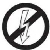
Warning symbol: Sunbed should be disconnected from power source

Warning symbol: Remove plug from socket

Warning symbol: Not for household use
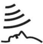
Symbol: Facial tanner

Symbol: Sunbed canopy

Symbol: Sunbed bed

Symbol: Vertical sunbed
Inhalt
Garantiebestimmungen....15
natural_image
Diagram showing a curved mechanical component with an arrow indicating rotation (no text or symbols)
natural_image
Diagram of a folded paper or plastic sheet with internal ridges and a curved arrow indicating direction (no text or symbols)
natural_image
Diagram of a curved architectural or mechanical component with internal cutouts and a black arrow pointing to a feature (no text or symbols present)


A: Start
Model: Luxura X3
Type: XXX
Serial number: 00 xx 001000
Rated voltage: 400V/3N\~/PE/50Hz
Rated power input: XX kW

XXXXXX

Maxlight XXX
Maxlight XXX
Ballast: XXX

Maxlight XXX
Ballast: XXX

Maxlight XXX
Ballast: XXX
Filter: XXX
Reflector: XXX
UV classification: XXX
Made by: Hapro International B.V.
PO Box 73
4420 AC Kapelle, Netherlands


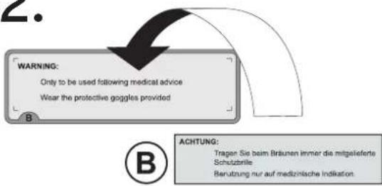
1.

2.

- Witmakers - in wasmiddelen
- Eosine - in kleurstoffen
- Gehalogeneerd salicylanilide - in schimmelwerende stoffen
natural_image
Diagram showing a curved surface with an arrow indicating rotation, labeled with number 2 (no text or symbols beyond label)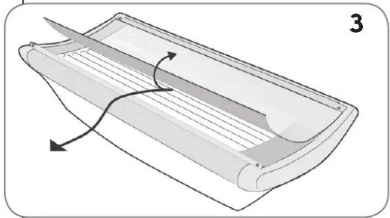
natural_image
Diagram of a folded paper or plastic sheet with internal ridges and a curved arrow indicating rotation (no text or symbols)

natural_image
Diagram of a curved architectural or mechanical component with internal compartments and a directional arrow (no text or symbols)
Bediening


A: Start
Model: Luxura X3
Type: XXX
Serial number: 00 xx 001000
Rated voltage: 400V/3N\~/PE/50Hz
Rated power input: XX kW

XXXXXX

Maxlight XXX
Maxlight XXX
Ballast: XXX

Maxlight XXX
Ballast: XXX

Maxlight XXX
Ballast: XXX
Filter: XXX
Reflector: XXX
UV classification: XXX
Made by: Hapro International B.V.
PO Box 73
4420 AC Kapelle, Netherlands


1.
2.


Alignment / Dimensions....48
natural_image
Diagram showing a curved mechanical component with an arrow indicating rotation (no text or symbols)
natural_image
Diagram of a folded paper or plastic sheet with internal ridges and a cutting tool, showing directional arrows (no text or symbols)

natural_image
Diagram of a curved architectural or mechanical structure with internal compartments and a directional arrow (no text or symbols)
Fonctionnement


A : Démarrage
Model: Luxura X3
Type: XXX
Serial number: 00 xx 001000
Rated voltage: 400V/3N\~/PE/50Hz
Rated power input: XX kW

XXXXXX

Maxlight XXX
Maxlight XXX
Ballast: XXX

Maxlight XXX
Ballast: XXX

Maxlight XXX
Ballast: XXX
Filter: XXX
Reflector: XXX
UV classification: XXX
Made by: Hapro International B.V.
PO Box 73
4420 AC Kapelle, Netherlands


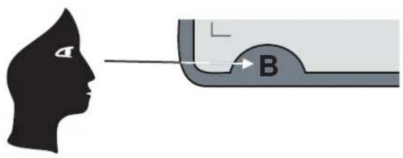
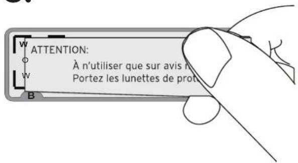
Les étiquettes

1.

2.

3.

other
| Lamp Type | Lamp Description | Time (min) | | :--- | :--- | :--- | | UV-type 3 | All lamps are 0,3 W/m² | 1st Session (min) | | UV-type 3 | All lamps are UV-type 3 | 2nd Session (min) | | UV-type 3 | All lamps are UV-type 3 | 3rd Session (min) | | UV-type 3 | All lamps are UV-type 3 | 4th Session (min) | | UV-type 3 | All lamps are UV-type 3 | 5th Session (min) | | UV-type 3 | All lamps are UV-type 3 | 6th Session (min) | | UV-type 3 | All lamps are UV-type 3 | 7th Session (min) | | UV-type 3 | All lamps are UV-type 3 | 8th Session (min) | | UV-type 3 | All lamps are UV-type 3 | 9th Session (min) | | UV-type 3 | All lamps are UV-type 3 | 10th Session (min) | | UV-type 3 | Max. tanning sessions a year | 60 (15kJ/m2) | | UV-type 3 | Max. tanning sessions a year | 43 (15kJ/m2) | | UV-type 3 | Max. tanning sessions a year | 33 (15kJ/m2) | | Sunburn (sensitivity to sunlight) | Skin types | Fair-skinned (II) | | Sunburn (sensitivity to sunlight) | Tanning effect | normal tanning | | Sunburn (sensitivity to sunlight) | Sunburn (sensitivity to sunlight) | mostly | | Dark-skinned (IV) | Dark-skinned (IV) | average (III) | | Dark-skinned (IV) | Dark-skinned (IV) | fast tanning | | Dark-skinned (IV) | Dark-skinned (IV) | fast tanning | | All lamps are 0,3 W/m² Important: Times listed apply to the specified lamps only, see specification sticker on the back of the appliance. For replacing UV lamps, see specification sticker on the back of the appliance. | All lamp are 0,3 W/m² Important: Times listed apply to the specified lamps only, see specification sticker on the back of the appliance. For replacing UV lamps, see specification sticker on the back of the appliance. | 1st Session (min) | | All lamp are 0,3 W/m² Important: Times listed apply to the specified lamps only, see specification sticker on the back of the appliance. For replacing UV lamps, see specification sticker on the back of the appliance. | All lamp are 0,3 W/m² Important: Times listed apply to the specified lamps only, see specification sticker on the back of the appliance. For replacing UV lamps, see specification sticker on the back of the appliance. | 2nd Session (min) | | All lamp are 0,3 W/m² Important: Times listed apply to the specified lamps only, see specification sticker on the back of the appliance. For replacing UV lamps, see specification sticker on the back of the appliance. For replacing UV lamps, see specification sticker on the back of the appliance. | All lamp are 0,3 W/m² Important: Times listed apply to the specified lamps only, see specification sticker on the back of the appliance. For replacing UV lamps, see specification sticker on the back of the appliance. For replacing UV lamps, see specification sticker on the back of the appliance. | 3rd Session (min) | | All lamp are 0,3 W/m² Important: Times listed apply to the specified lamps only, see specification sticker on the back of the appliance. For replacing UV lamps, see specification sticker on the back of the appliance. For replacing UV lamps, see specification sticker on the back of the appliance. For replacing UV lamps, see specification sticker on the back of the appliance. For replacing UV lamps, see specification sticker on the back of the appliance. For replacing UV lamps, see specification sticker on the back of the appliance. For replacing UV lamps, see specification sticker on the back of the appliance. For replacing UV lamps, see specification sticker on the back of the appliances. For replacing UV lamps, see specification sticker on the back of the appliance. For replacing UV lamps, see specification sticker on the back of the appliance. For replacing UV lamps, see specification sticker on the back of the appliance. For replacing UV lamps, see specification sticker on the back of the appliance. For replacing UV lamps, see specification sticker on the back of the appliance. For replacing UV lamps, see specification sticker on the back of the appliance. For replacing UV lamps, see specification sticker in light exposure. For replacing UV lamps, see specification sticker in light exposure. For replacing UV lamps, see specification sticker in light exposure. For replacing UV lamps, see specification sticker in light exposure. For replacing UV lamps, see specification sticker in light exposure. For replacing UV lamps, see specification sticker in light exposure. For replacing UV lamps, see specification sticker in light exposure. For replacing UV lamps, see specification sticker in light exposure. For replacing UV lamps, see specification sticker in light exposure. For replacingUVlamps, see specification sticker in light exposure at min; for UVlamps, see specification sticker in light exposure at min; for UVlamps, see specification sticker in light exposure at min; for UVlamps, see specification sticker in light exposure at min; for UVlamps, see specification sticker in light exposure at min; for UVlamps, see specification sticker in light exposure at min; for UVlamps, see specification sticker in light exposure at min; for UVlamps, see specification sticker in light exposure at min; for UVlamp, see specification sticker in light exposure at min; for UVlamp, see specification sticker in light exposure at min; for UVlamp, see specification sticker in light exposure at min; for UVlamp, see specification sticker in light exposure at min; for UVlamp, see specification sticker in light exposure at min; for UVlamp, see specification sticker in light exposure at min; for UVlamp, see specification sticker in light exposure at min; for UVlamp, See Specification Sticker in Light Exposure at min; for UVlamp, See Specification Sticker in Light Exposure at min; for UVlamp, See Specification Sticker in Light Exposure at min; for UVlamp, See Specification Sticker in Light Exposure at min; for UVlamp, See Specification Sticker in Light Exposure at min; for UVlamp, See Specification Sticker in Light Exposure at min; for UVlamp, See Specification Sticker in Light Exposure at min; for UVlamp, See Standard Session at min; for UVlamp, See Standard Session at min; for UVlamp, See Standard Session at min; for UVlamp, See Standard Session at min; for UVlamp, See Standard Session at min; for UVlamp, See Standard Session at min; for UVlamp, See Standard Session at min; for UVlamp, See Standard Session at min; for UVlamp, See Standard Session at min; for UVlamp, See Standard Sessionat min; for UVlamp, See Standard Session at min; for UVlamp, See Standard Session at min; for UVlamp, See Standard Session at min; for UVlamp, See Standard Session at min; for UVlamp, See Standard Session at min; for UVlamp, See Standard Session at min; for UVlamp, See Standard Session at min; for UVlamp, See Standard Session at min; for UVlamp, See Standard Session at max. (15kJ/m2).Warning!: Allow at least 48 hours between the first two exposures.
Bräunungstabelle

Numbered Wattage of lamps =
4 x 80W
22 x 100W
1×300W
Weight 150 kg
Luxura X3 30 SPr
Voltage (Fuse) Wattage
230V/I-N/PE/50Hz 1x20A 4.0kW
230V/3\~PE/50Hz 3 x 16A 4.0kW
230V/I\~N/PE/50Hz 3 x 16A 4,0kW
Note!
For UK only!
420V/3-N/PE/50Hz 3 x 16A 4.2kW
Numbered Wattage of lamps
14×100W
14×120W
9×25W
Weight
167 kg
Luxura X3 28 SLi
Voltage (Fuse) Wattage
230V/1-N/PE/50Hz 1x20A 4.5kW
230V/3-PE/50Hz 3 x 16A 4.5kW
400V/1-N/PE/50Hz 3 x 16A 4.5kW
Note!
For UK only!
420V/3\~N/PE/50Hz 3 x 16A 4.7kW
Numbered Wattage of lamps =
14 x 80W
14 x 100W
3×300W
Weight
170 kg
Luxura X3 30 SLi
Voltage (Fuse) Wattage
230V/I-N/PE/50Hz 1x20A 5kW
230V/3\~PE/50Hz 3 x 16A 5kW
400V/3-N/PE/50Hz 3 x 16A 5kW
Note!
For UK only!
420V/3\~N/PE/50Hz 3 x 16A 5,2kW
Numbered Wattage of lamps =
30×100W
3×300W
Weight
180 kg

natural_image
Diagram of a mechanical assembly with lever arms and a block on a conveyor belt, showing motion direction (no text or symbols)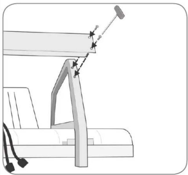
natural_image
Diagram of a mechanical assembly with a lever and attached components, showing motion indicators (no text or symbols)GB
Secure the two support feet to the underside of the sunbed with 16 round headed screws (4.2mm X 13mm). Keep the hinge arm on the rear away from the sunbed (see drawing)
D
Fit the connection panel to the support feet (see drawing) with 4 round headed screws (m6 x 20mm). Then turn the sunbed over. Caution: when turning the sunbed over do not use the support feet!
D

GB
Place the sleeve bearings in the bearing bushes of the canopy (1). Now place the canopy on the sunbed (2), connect the hinge points using the bearing bushes (3) and secure these with the hexagonal bolts (M8) (4).
D
Fit the two plugs of the sunbed to the rear of the canopy as indicated.
D
GB
Open the canopy and fit the gas springs as per drawing. The gas spring casing on the canopy side (1). Place the fork pins (2) and secure these with the securing clips (3).
D
natural_image
Technical diagram of a mechanical component with arrows indicating assembly or force direction (no text or symbols present)GB Place the side panels under the sunbed and ensure that these fall into the recesses of the end covers (see 1). NB: the side panels at the rear will fall within the support feet.
Slide the front panel (1) into the rebate (2) and secure it with 2 round headed screws (m6 x 12mm) to the support feet through the holes in the side panels.
D
GB
Remove the foil from the adhesive film (1) and place the cover panel (2) against the side panels and the front panel. Press the whole assembly firmly.
D
Check when connecting to the mains supply the type of supply available to you. Various connections according to fig. 2, 3 and 4 (factory connections).
D

fig. 3

Powerprint


Optional Optionell Optioneel En option

natural_image
Diagram of a mechanical assembly with a spring and pin, showing alignment and mounting features (no text or symbols)GB
Assembly decoration shield
Fit the decoration shield to the two support feet and secure with 2 round headed screws.
D
Montage Decorationshield
All supply circuits must be disconnected!
natural_image
Technical diagram of a roof structure with support pillars and grounding symbols (no text or labels)GB
Assembly facial blower
Remove the 3 screws from the rear of the cover panel.
D
natural_image
Diagram of a curved structure with vertical bars and three hanging objects, no text or symbols present
GB Remove the covers from the canopy.
GB Remove the 3 caps as indicated.
GB Fit the blower to the end cover. Pull the power cable through the second hole (see drawing)
GB Fit the plug to the blower cable.
GB Connect the plug.
natural_image
Diagram of a car interior showing a roof-mounted panel with two arrows pointing to the panel (no text or symbols present)
natural_image
Diagram of a mechanical component with two upward arrows indicating motion or force, no text or symbols present
natural_image
Diagram of a car interior showing a roof, door, and window with arrows indicating movement or force (no text or symbols present)Adjustments of the gas springs.Einstellen der Gasdruckfedern.
After placing the optional headfan or when the gas springs are not strong enough, the canopy may come down too fast. This can be avoided by removing one or more ballast plates.
1 Remove the middle cover canopy (1)
2 Remove the ballast plate (2)
3 Place the middle cover canopy (3)
4 Check this adjustment
If the canopy is still coming down to fast, another ballast plate can be removed.
*Checking the adjustment of the gas springs should always be performed after the tanning unit has been turned on for at least 10 minutes. Gas springs tend to get stronger as they get warmer.
*If an optional headfan is placed, 4 ballast plates should be removed.
*If the supplied gas springs are different in strength. The strongest gas spring can be used on either side of the tanning unit.
| Pos. | Description | Art. no. |
| 1 | Decorationshield 11721 | |
| 2 | Acrylic bench short 11343 | |
| Acrylic bench long 11274 | ||
| 3 | Endcover bench 11263 | |
| 4 | Plastic sideprofile bench short 11337 | |
| Plastic sideprofile bench long 11117 | ||
| 5 | Sidecover bench 11262 | |
| 6 | Frontcover bench short 15013 | |
| Frontcover bench long 14818 | ||
| 7 | Part frontcover short 11521 | |
| Part frontcover long 11520 | ||
| 8 | Combi frame (Ral 9006) 11293 | |
| 9 | Connection bar 11290 | |
| 10 | Fan 07561 | |
| 11 | Fan housing 11329 | |
| 12 | Acrylic support short 11339 | |
| Acrylic support long 11338 |
Miscellaneous parts

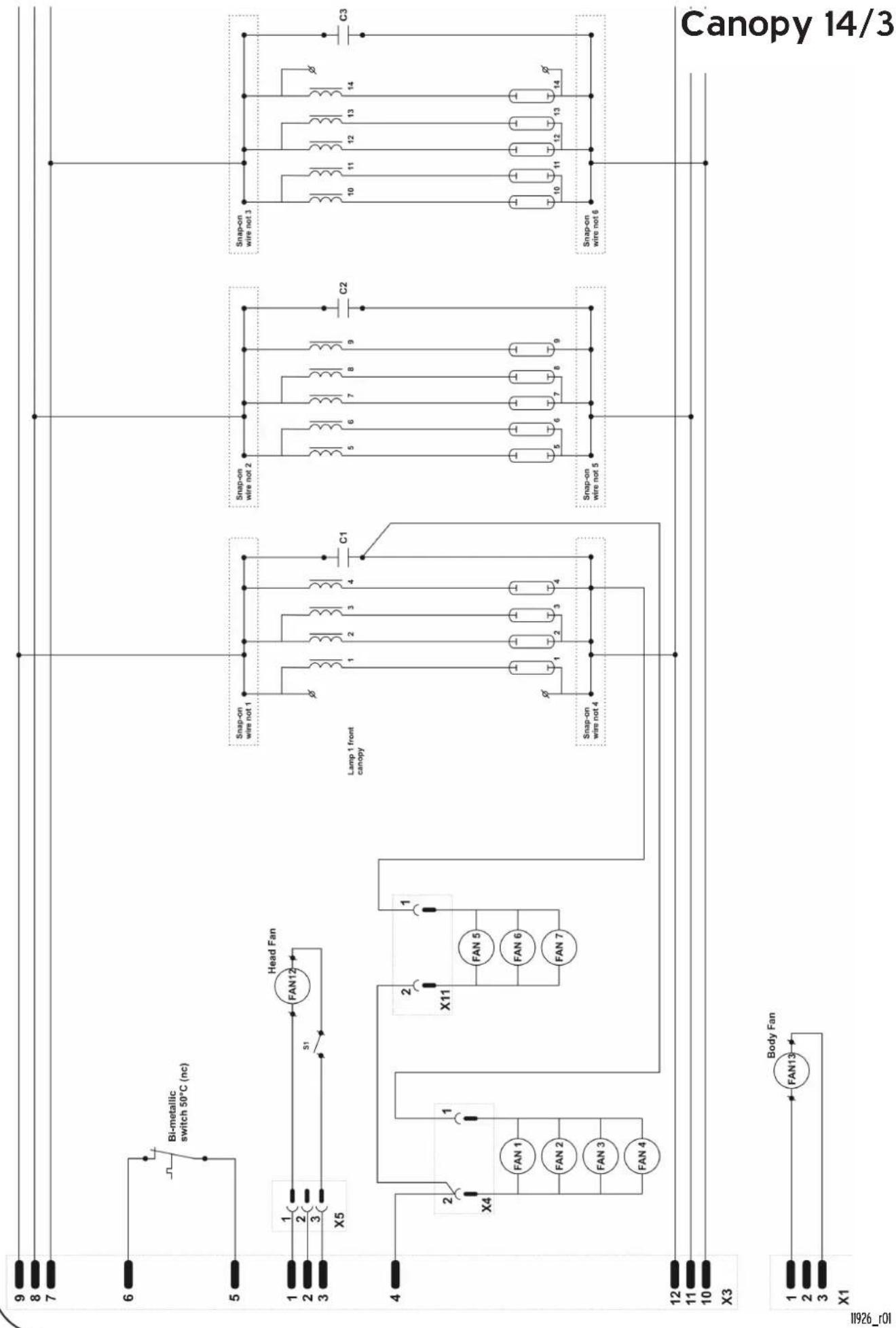
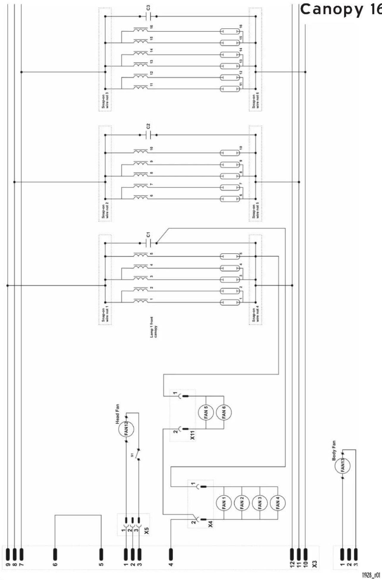
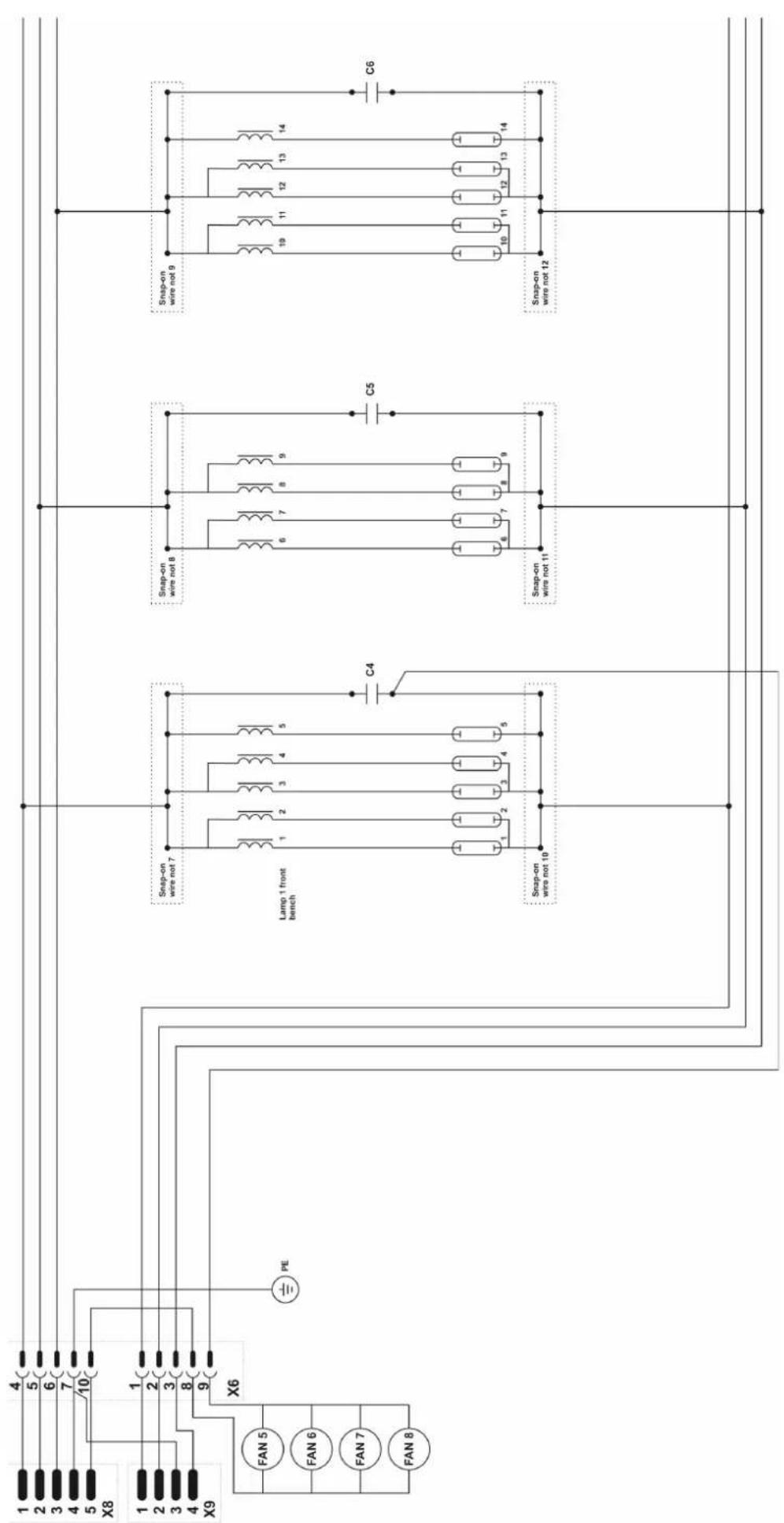
Electrical diagrams
Schaltpläne

flowchart
graph TD
    A["Print"] --> B["16"]
    B --> C["15"]
    C --> D["14"]
    D --> E["13"]
    E --> F["12"]
    F --> G["11"]
    G --> H["10"]
    H --> I["9"]
    I --> J["8"]
    J --> K["7"]
    K --> L["6"]
    L --> M["5"]
    M --> N["4"]
    N --> O["3"]
    O --> P["2"]
    P --> Q["1"]
    Q --> R["X1"]
    R --> S["1"]
    S --> T["X2"]
    T --> U["1"]
    U --> V["X3"]
    V --> W["12"]
    W --> X["11"]
    X --> Y["10"]
    Y --> Z["9"]
    Z --> AA["8"]
    AA --> AB["7"]
    AB --> AC["6"]
    AC --> AD["5"]
    AD --> AE["4"]
    AE --> AF["3"]
    AF --> AG["2"]
    AG --> AH["1"]
    AH --> AI["X1"]
    AI --> AJ["X2"]
    AJ --> AK["12"]
    AK --> AL["11"]
    AL --> AM["10"]
    AM --> AN["9"]
    AN --> AO["8"]
    AO --> AP["7"]
    AP --> AQ["6"]
    AQ --> AR["5"]
    AR --> AS["4"]
    AS --> AT["3"]
    AT --> AU["2"]
    AU --> AV["1"]
    AV --> AW["X3"]
    AW --> AX["X2"]
    AX --> AY["12"]
    AY --> AZ["11"]
    AZ --> BA["10"]
    BA --> BB["9"]
    BB --> BC["8"]
    BC --> BD["7"]
    BD --> BE["6"]
    BE --> BF["5"]
    BF --> BG["4"]
    BG --> BH["3"]
    BH --> BI["2"]
    BI --> BJ["1"]
    BJ --> BK["X1"]
Control 3 fase


flowchart
graph TD
    subgraph Canopy_14/1
        A["Canopy 14/1"] --> B["Body Fan"]
        B --> C["X1"]
        B --> D["X2"]
        B --> E["X3"]
        B --> F["107_12611"]
        G["Canopy 14/1"] --> H["Body Fan"]
        H --> I["X1"]
        H --> J["X2"]
        H --> K["X3"]
        H --> L["107_12611"]
        M["Canopy 14/1"] --> N["Body Fan"]
        N --> O["X1"]
        N --> P["X2"]
        N --> Q["X3"]
        N --> R["107_12611"]
        S["Canopy 14/1"] --> T["Body Fan"]
        T --> U["X1"]
        T --> V["X2"]
        T --> W["X3"]
        T --> X["107_12611"]
        Y["Canopy 14/1"] --> Z["Body Fan"]
        Z --> AA["X1"]
        Z --> AB["X2"]
        Z --> AC["X3"]
        Z --> AD["107_12611"]
        AE["Canopy 14/1"] --> AF["Body Fan"]
        AF --> AG["X1"]
        AF --> AH["X2"]
        AF --> AI["X3"]
        AF --> AJ["107_12611"]
        AK["Canopy 14/1"] --> AL["Body Fan"]
        AL --> AM["X1"]
        AL --> AN["X2"]
        AL --> AO["X3"]
        AL --> AP["107_12611"]
        AQ["Canopy 14/1"] --> AR["Body Fan"]
        AR --> AS["X1"]
        AR --> AT["X2"]
        AR --> AU["X3"]
        AR --> AV["107_12611"]
        AW["Canopy 14/1"] --> AX["Body Fan"]
        AX --> AY["X1"]
        AX --> AZ["X2"]
        AX --> BA["X3"]
        AX --> BB["107_12611"]
        BC["Canopy 14/1"] --> BD["Body Fan"]
        BD --> BE["X1"]
        BD --> BF["X2"]
        BD --> BG["X3"]
        BD --> BH["107_12611"]
        BI["Canopy 14/1"] --> BJ["Body Fan"]
        BJ --> BK["X1"]
        BJ --> BL["X2"]
        BJ --> BM["X3"]
        BJ --> BN["107_12611"]
        BO["Canopy 14/1"] --> BP["Body Fan"]
        BP --> BQ["X4"]
        BP --> BR["X5"]
        BP --> BS["Head Fan"]
    end
    subgraph Wireless Components
        CA["Canopy 14/1"] --> CB[Capacitor 9x9-9x8-9x7-9-8-7-6-5-4-3-2-1-0-0-0-0-0-0-0-0-0-0-0-0-0-0-0-0-0-0-0-0-0-0-0-0-0-0-0-0-0-0-0-0-0-0-0-0-0-0-0-0-0-0-0-0-0-0-0-0-0-0-3
    end
    subgraph Wireless Connections
        CA
    end
    subgraph Capacitors
        CB
    end
    subgraph Power Supply
        CB
    end
    subgraph Load Connections
        DB
    end
    subgraph Head Fenns
        DB
    end
    subgraph Feed Connections
        DB
    end
    subgraph Power Supply Connections
        DB
    end
flowchart
graph TD
    subgraph Top_Lower_Circuit
        A["1"] --> B["2"]
        B --> C["3"]
        C --> D["X5"]
        D --> E["Head Fan"]
        E --> F["FAN12"]
        F --> G["31"]
        G --> H["X11"]
        H --> I["FAN 5"]
        I --> J["FAN 6"]
        J --> K["FAN 7"]
    end

    subgraph Bottom_Lower_Circuit
        L["1"] --> M["2"]
        M --> N["X1"]
        N --> O["FAN13"]
        O --> P["Body Fan"]
    end

    subgraph Top_Lower_Circuit
        Q["1"] --> R["2"]
        R --> S["X4"]
        S --> T["FAN 1"]
        T --> U["FAN 2"]
        U --> V["FAN 3"]
        V --> W["FAN 4"]
    end

    subgraph Bottom_Lower_Circuit
        X["1"] --> Y["2"]
        Y --> Z["X3"]
    end

    subgraph Top_Lower_Circuit
        AA["1"] --> AB["2"]
        AB --> AC["X1"]
        AC --> AD["FAN13"]
    end

    subgraph Bottom_Lower_Circuit
        AE["1"] --> AF["2"]
        AF --> AG["X3"]
    end

    subgraph Top_Lower_Circuit
        AH["1"] --> AI["2"]
        AI --> AJ["X1"]
        AJ --> AK["FAN13"]
    end

    subgraph Bottom_Lower_Circuit
        AL["1"] --> AM["2"]
        AM --> AN["X3"]
    end

    subgraph Top_Lower_Circuit
        AO["1"] --> AP["2"]
        AP --> AQ["X1"]
        AQ --> AR["FAN13"]
    end

    subgraph Bottom_Lower_Circuit
        AS["1"] --> AT["2"]
        AT --> AU["X3"]
    end

    subgraph Top_Lower_Circuit
        AV["1"] --> AW["2"]
        AW --> AX["X1"]
        AX --> AY["FAN13"]
    end

    subgraph Bottom_Lower_Circuit
        AZ["1"] --> BA["2"]
        BA --> BB["X3"]
    end

    subgraph Top_Lower_Circuit
        BC["1"] --> BD["2"]
        BD --> BE["X1"]
        BE --> BF["FAN13"]
    end

    subgraph Bottom_Lower_Circuit
        BG["1"] --> BH["2"]
        BH --> BI["X3"]
    end

    subgraph Top_Lower_Circuit
        BJ["1"] --> BK["2"]
        BK --> BL["X1"]
        BL --> BM["FAN13"]
    end

    subgraph Bottom_Lower_Circuit
        BN["1"] --> BO["2"]
        BO --> BP["X3"]
    end

    subgraph Top_Lower_Circuit
        BQ["1"] --> BR["2"]
        BR --> BS["X1"]
        BS --> BT["FAN13"]
    end

    subgraph Bottom_Lower_Circuit
        BU["1"] --> BV["2"]
        BV --> BW["X3"]
    end

    subgraph Top_Lower_Circuit
        BX["1"] --> BY["2"]
        BY --> BZ["X1"]
        BZ --> CA["FAN13"]
    end

    subgraph Bottom_Lower_Circuit
        CB["1"] --> CC["2"]
        CC --> CD["X3"]
    end

    subgraph Top_Lower_Circuit
        CE["1"] --> CF["2"]
        CF --> CG["X1"]
        CG --> CH["FAN13"]
    end

    subgraph Bottom_Lower_Circuit
        CI["1"] --> CJ["2"]
        CJ --> CK["X3"]
    end

    subgraph Top_Lower_Circuit
        CL["1"] --> CD
        CD --> CD
        CD --> CE
    end

    subgraph Bottom_Lower_Circuit
        CM["1"] --> CN["2"]
        CN --> CO["X1"]
        CO --> CP["FAN13"]

    subgraph Top_Lower_Circuit
        CR["1"] --> CS["2"]
        CS --> CS
        CS --> CT["X3"]
    end

    subgraph Bottom_Lower_Circuit
        CU["1"] --> CV["2"]
        CV --> CV
        CV --> CW["X3"]
    end

    subgraph Top_Lower_Circuit
        CX["1"] --> CY["2"]
        CY --> CY
        CY --> CZ["X3"]
    end

    subgraph Bottom_Lower_Circuit
        DD["1"] --> DE["2"]
        DE --> DE
        DE --> DV["X3"]
    end

    subgraph Top_Lower_Circuit
        DW["1"] --> DW
        DW --> DW
        DW --> DW
        DW --> DW
    end

    subgraph Bottom_Lower_Circuit
        DX["1"] --> DX
        DX --> DX
        DX --> DX
        DX --> DX
    end

11929_r01
flowchart
graph TD
    A["Canopy 16"] --> B["Body Fan"]
    B --> C["1"]
    B --> D["2"]
    B --> E["3"]
    B --> F["10"]
    B --> G["10"]
    B --> H["11"]
    B --> I["12"]
    B --> J["12"]
    B --> K["15"]
    B --> L["16"]
    B --> M["19"]
    B --> N["14"]
    B --> O["13"]
    B --> P["12"]
    B --> Q["11"]
    B --> R["10"]
    B --> S["9"]
    B --> T["8"]
    B --> U["7"]
    B --> V["6"]
    B --> W["5"]
    B --> X["4"]
    B --> Y["3"]
    B --> Z["2"]
    B --> AA["1"]
    B --> AB["0"]
    B --> AC["1"]
    B --> AD["2"]
    B --> AE["5"]
    B --> AF["6"]
    B --> AG["9"]
    B --> AH["10"]
    B --> AI["11"]
    B --> AJ["12"]
    B --> AK["15"]
    B --> AL["16"]
    B --> AM["19"]
    B --> AN["20"]
    B --> AO["21"]
    B --> AP["22"]
    B --> AQ["23"]
    B --> AR["24"]
    B --> AS["25"]
    B --> AT["26"]
    B --> AU["27"]
    B --> AV["28"]
    B --> AW["29"]
    B --> AX["30"]
    B --> AY["31"]
    B --> AZ["32"]
    B --> BA["33"]
    B --> BB["34"]
    B --> BC["35"]
    B --> BD["36"]
    B --> BE["37"]
    B --> BF["38"]
    B --> BG["39"]
    B --> BH["40"]
    B --> BI["41"]
    B --> BJ["42"]
    B --> BK["43"]
    B --> BL["44"]
    B --> BM["45"]
    B --> BN["46"]
    B --> BO["47"]
    B --> BP["48"]
    B --> BQ["49"]
    B --> BR["50"]
    B --> BS["51"]
    B --> BT["X5"]
    B --> BU["X6"]
    B --> BV["X7"]
    B --> BW["X8"]
    B --> BX["X9"]
    B --> BY["X10"]
    B --> BZ["X11"]
    B --> CA["X12"]
    B --> CB["X13"]
    B --> CC["X14"]
    B --> CD["X15"]
    B --> CE["X16"]
    B --> CF["X17"]
    B --> CG["X18"]
    B --> CH["X19"]
    B --> CI["X20"]
    B --> CJ["X21"]
    B --> CK["X22"]
    B --> CL["X23"]
    B --> CM["X24"]
    B --> CN["X25"]

flowchart
graph TD
    subgraph Top_Lower_Circuit
        A["6"] --> B["Bi-metallic switch 50°C (nc)"]
        B --> C["X5"]
        C --> D["FAN12"]
        D --> E["S1"]
        E --> F["Head Fan"]
        F --> G["X4"]
        G --> H["FAN 1"]
        G --> I["FAN 2"]
        G --> J["FAN 3"]
        G --> K["FAN 4"]
        L["1"] --> M["X5"]
        N["2"] --> O["X5"]
        P["3"] --> Q["X5"]
    end

    subgraph Bottom_Lower_Circuit
        R["1"] --> S["X4"]
        T["2"] --> U["X4"]
        V["3"] --> W["X4"]
        X["4"] --> Y["X4"]
        Z["2"] --> AA["X11"]
        AB["1"] --> AC["X11"]
        AD["2"] --> AE["X11"]
        AF["1"] --> AG["X11"]
        AH["2"] --> AI["X11"]
        AJ["3"] --> AK["X11"]
        AL["FAN 5"] --> AM["FAN 6"]
        AN["FAN 7"] --> AO["FAN 7"]
    end

    subgraph Top_Lower_Duplexing_Lamp
        AP["Lamp 1 front canopy"] --> AQ["C1"]
        AQ --> AR["C2"]
        AR --> AS["C3"]

        AT["Lamp 1 front canopy"] --> AU["C1"]
        AU --> AV["C2"]
        AV --> AW["C3"]

        AX["Lamp 1 front canopy"] --> AY["C1"]
        AY --> AZ["C2"]
        AZ --> BA["C3"]

        BB["Lamp 1 front canopy"] --> BC["C1"]
        BC --> BD["C2"]
        BD --> BE["C3"]

        BF["Lamp 1 front canopy"] --> BG["C1"]
        BG --> BH["C2"]
        BH --> BI["C3"]

        BJ["Lamp 1 front canopy"] --> BK["C1"]
        BK --> BL["C2"]
        BL --> BM["C3"]

        BN["Lamp 1 front canopy"] --> BO["C1"]
        BO --> BP["C2"]
        BP --> BQ["C3"]

        BR["Lamp 1 front canopy"] --> BS["C1"]
        BS --> BT["C2"]
        BT --> BU["C3"]

        BV["Lamp 1 front canopy"] --> BW["C1"]
        BW --> BX["C2"]
        BX --> BY["C3"]

        BZ["Lamp 1 front canopy"] --> CA["C1"]
        CA --> CB["C2"]
        CB --> CC["C3"]

        DA["Lamp 1 front canopy"] --> DB["C1"]
        DB --> DC["C2"]
        DC --> DD["C3"]

        DE["Canopy 16/3"] --> EF["Output Line"]
    end
11884_r01

flowchart
graph TD
    subgraph_Panel1["9 x Soft (option)"]
        A["C7"] --> B["1"]
        B --> C["2"]
        C --> D["3"]
        D --> E["4"]
        E --> F["5"]
        F --> G["6"]
        G --> H["7"]
        H --> I["8"]
        I --> J["9"]
        J --> K["Snap-on wire not 13"]
    end

    subgraph_Panel2["1 x GB (option)"]
        L["I1"] --> M["2"]
        M --> N["HPA 400/30S Middle"]
        N --> O["3"]
        O --> P["HPA 400/30S Front"]
        P --> Q["3"]
        Q --> R["HPA 400/30S Rear"]
        R --> S["3"]
        S --> T["C7"]
        T --> U["2"]
        U --> V["C8"]
        V --> W["Sw1#"]
        W --> X["Sw2#"]
        X --> Y["Sw1#"]
        Y --> Z["C7"]
        Z --> AA["2"]
        AA --> AB["C8"]
        AB --> AC["3"]
        AC --> AD["C9"]
        AD --> AE["Sw1#"]
        AE --> AF["Sw2#"]
        AF --> AG["Sw3#"]
    end

    subgraph_Panel3["2 x GB (option)"]
        AH["I1"] --> AI["2"]
        AI --> AJ["HPA 400/30S Front"]
        AJ --> AK["HPA 400/30S Middle"]
        AK --> AL["3"]
        AL --> AM["HPA 400/30S Rear"]
        AM --> AN["3"]
        AN --> AO["C7"]
        AO --> AP["2"]
        AP --> AQ["C8"]
        AQ --> AR["3"]
        AR --> AS["C9"]
        AS --> AT["Sw1#"]
        AT --> AU["Sw2#"]
        AU --> AV["Sw3#"]
    end

    Panel4["3 x GB (option)"]
    subgraph Facials
        AW["X2"] --> AX["1"]
        AX --> AY["8"]
        AY --> AZ["7"]
        AZ --> BA["6"]
        BA --> BB["X2"]
    end

    A -->|Snap-on wire not 13| BC
    BC -->|C7| BD
    BC -->|Sw1#| BE
    BC -->|Sw2#| BF
    BC -->|Sw3#| BG
    style Panel4 fill:#f9f,stroke:#333,stroke-width:2px
    style Facials fill:#ccf,stroke:#333,stroke-width:2px

Bench 12
11881_r01
Bench 14
11882_r01

natural_image
Blue and silver handheld water dispenser (no visible text or symbols)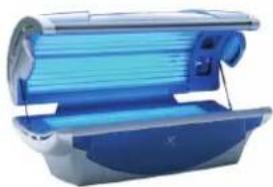
natural_image
Blue and silver photo of a medical imaging machine (no visible text or symbols)Manufacturer:
Hapro International b.v..
Fleerbosseweg 33
4420 AC Kapelle. The Netherlands.
www.hapro.com
Product identification:
Product: Tanning equipment
Model: Luxura X3
Type: 26 SLi, 28 SLi, 30 DPC, 30 Sli, 30 SPr, 30XLc
Means of conformity:
The products are in conformity with Directive 89/336/EC of the European Community and the Low-Voltage Directive 2006/95/EC of the European Community.
Testing, Electro-Magnetic Compatibility:
Carried out by: Hapro Laboratory,
Fleerbosseweg 33
4420 AC Kapelle. The Netherlands.
Standards used: EN 61000-6-3:2001; EN 55022:1998; EN 61000-6-1:2001
EMC Certificate no.: BBB 03-182
Testing, Low-Voltage Directive:
Carried out by: Hapro Laboratory.
Fleerbosseweg 33
4420 AC Kapelle. The Netherlands.
Standards used: EN 50366:2003; EN 60335-1:2002; EN 60335-2:27:2003
KEMA no.: 2029660.01
KEYMARK no.: 2029660.02
Declaration of conformity
15423_04
CE

KEMA EUR
Representative:
Name: D.C. van de Linde
Function: Managing Director

a VDL Company
Date: 01-02-2007
Signature:


- X _3
- Warranty
- Not covered under this warranty
- Note:
- Read this first
- Golden rules for sensible tanning
- Removing the acrylic sheets
- Remove face tanners. (optional)
- Information on lamps
- Lamps Type
- maxlight HP 400W D
- Information on the “permanent label” on the cubicle wall
- Inhalt
- 1.
- 2.
- Bediening
- Fonctionnement
- Les étiquettes
- 3.
- Luxura X3 30 SPr
- Note!
- Luxura X3 28 SLi
- Luxura X3 30 SLi
- GB
- D
- Optional Optionell Optioneel En option
- Adjustments of the gas springs.Einstellen der Gasdruckfedern.
- Miscellaneous parts
- Manufacturer:
- Product identification:
- Means of conformity:
- Testing, Electro-Magnetic Compatibility:
- Testing, Low-Voltage Directive:
- Representative:
Brand : CASO
Model : X3
Category : Kitchen scale