
Z3 PC-Link - Meter VDO - Free user manual and instructions
Find the device manual for free Z3 PC-Link VDO in PDF.


| Brand | VDO |
| Model | Z3 PC-Link |
| Product Type | Cycling Computer |
| Dimensions | 70 x 50 x 25 mm |
| Weight | 50 g |
| Power Source | CR2032 battery |
| Display | LCD, multi-line |
| Speed Measurement | Current, average, maximum |
| Distance Measurement | Trip and total distance |
| Time Functions | Clock, ride time, stopwatch |
| PC Connectivity | USB PC-Link for data transfer |
| Water Resistance | IPX4 splash proof |
| Mounting | Handlebar bracket included |
| Sensor Type | Wireless (speed and cadence optional) |
| Memory | Stores up to 10 rides |
| Battery Life | Approximately 1 year |
| Maintenance | Clean with dry cloth; replace battery when low |
| Safety | Do not expose to extreme temperatures; avoid impact |
| Spare Parts | Battery cover, mounting bracket, sensor |
| Repairability | Battery user-replaceable; other repairs by service center |
| Warranty | 2 years |
Frequently Asked Questions - Z3 PC-Link VDO
User questions about Z3 PC-Link VDO
0 question about this device. Answer the ones you know or ask your own.
Ask a new question about this device
Download the instructions for your Meter in PDF format for free! Find your manual Z3 PC-Link - VDO and take your electronic device back in hand. On this page are published all the documents necessary for the use of your device. Z3 PC-Link by VDO.
USER MANUAL Z3 PC-Link VDO
VDO SERIES-Z
FOR CYCLING
73 PC-LINK
INSTRUCTION MANUAL / BEDIENUNGSANLEITUNG / MANUEL D'INSTALLATION ET D'UTILISATION / HANDLEIDING / MANUALE D'INSTALLAZIONE E FUNZIONAMENTO INSTRUKCJA OBSLUGI LICZNIKA / INSTALACION Y OPERACIÓN MANUAL
My Settings

| AGE: | WEIGHT: | MAX HEARTRATE: |
| LIMIT 1: LOW: HIGH: | ||
| LIMIT 2: LOW: HIGH: | ||
| LIMIT 3: LOW: HIGH: | ||
| RECOVERY PULSE: RECOVERY TIME: | ||
| BIKE 1 WEIGHT: | BIKE 2 WEIGHT: | |
| BIKE 1 WHEELSIZE: | BIKE 2 WHEELSIZE: | |
| BIKE 1 SERVICE INTERVAL: | BIKE 2 SERVICE INTERVAL: | |
| HOME ALTITUDE: | ||
| FURTHER SETTINGS: |
Picturebook
P01

natural_image
Line drawings of various smartwatch components including case, head, and display (no text or symbols)ONLY FOR MODELS
Z2 PC-LINK / Z3 PC-LINK

natural_image
Line drawing of a medical device with a clamped band and connector (no text or symbols)* Watch out: old batteries require special disposal B Please read instructions for end-off-life disposal treatment


Picturebook
P03
ONLY FOR
MODELS
Z2/Z2 PC-LINK
Z3/Z3 PC-LINK
Picturebook
P04/05


flowchart
graph TD
    A["Device Lock"] -->|1. LOCK| B["Device Unlock"]
    B -->|2. CLICK| C["Device Unlock"]
    C -->|2. UNLOCK| D["Device Unlock"]

Picturebook
P08
ONLY FOR
MODELS
Z2/Z2 PC-LINK
Z3/Z3 PC-LINK

natural_image
Line drawings of a hand gripping a car seatbelt, showing three different designs (no text or symbols)
natural_image
Line drawing of a human torso with a bandage and belt, no text or symbols present
natural_image
Line drawing of a human torso with a bandage on the chest (no text or symbols)Picturebook
P09 P09-2

natural_image
Line drawing of hands using a tool to adjust or install a mechanical component (no text or symbols present)
| Tire size | WS in mm KMH | WS in inch MPH | |
| 47-305 | 16x1,75 | 1272 | 50,1 |
| 47-406 | 20x1,75 | 1590 | 62,6 |
| 34-540 | 24x1 | 3/8 | 1948 |
| 47-507 | 24x1,75 | 1907 | 75,1 |
| 23-571 | 26x1 | 1973 | 77,7 |
| 40-559 | 26x1,5 | 2026 | 79,8 |
| 47-559 | 26x1,6 | 2051 | 80,7 |
| 47-559 | 26x1,75 | 2055 | 80,9 |
| 50-559 | 26x1,9 | 2060 | 81,1 |
| n/a 26 x 1,95 | 20x0 81,5 | ||
| 54-559 | 26x2,00 | 2075 | 81,7 |
| n/a 26 x 2,1 | 2060 81,9 | ||
| 57-559 | 26x2,125 | 2133 | 84,0 |
| 37-590 | 26x1 | 3/8 | 2105 |
| Tire size | WS in mm KMH | WS in inch MPH | ||
| 20-571 | 26x3/4 | 1954 | 76,9 | |
| 32-630 | 27x1 | 1/4 | 2199 | |
| 312-622 | 28x1,5 | 2224 | 87,6 | |
| 47-622 | 28x1,75 | 2268 | 88,3 | |
| 40-635 | 28x1 | 1/2 | 2265 | |
| 37-622 | 28x1 | 3/9 | 2205 | |
| 18-622 | 700x18C | 2102 | 82,8 | |
| 20-622 | 700x20C | 2114 | 83,2 | |
| 23-622 | 700x23C | 2133 | 84,0 | |
| 25-622 | 700x75C | 2146 | 84,5 | |
| 28-622 | 700x28C | 2149 | 84,6 | |
| 32-622 | 700x32C | 2174 | 85,6 | |
| 37-622 | 700x37C | 2205 | 86,8 | |
| 310-622 | 700x10C | 2224 | 87,6 | |
86,6 80,2 86,8
Picturebook
P11
ONLY FOR
MODELS
Z2 PC-LINK
Z3 PC-LINK

EN
Congratulations
With your selection of a VDO Z3 PC-Link you have opted for high-quality sports information computer. In order to fully benefit from the potential of the computer, we recommend that you carefully read this manual. It contains all operating instructions and many useful tips.
We extend our best wishes for enjoyment and satisfaction when riding with your VDO computer.
VDO Cyclecomputing Cycle Parts GmbH
Package contents >>> P01
First, please ensure that the contents of this package are complete:
1 VDO computer Z3PC-Link
1 VDO speed transmitter
1 VDO pulse-chest belt incl. elastic strap, incl. battery
1 battery for computer, 3 V type 2032
1 handlebar holder
1 wrist band holder
1 lock for the wrist band holder
1 spoke magnet
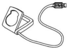
1 docking station with USB cable for data transfer to the PC
1 CD-ROM with analysis software for the PC
8 cable ties
Optional extension set:
VDO cadence transmitter
P..
Reference to the appropriate pages in the picture book. This is where the content is again presented in picture form, e.g.:
P01 -P01 page 1 in the picture book
INSTRUCTION MANUAL
TABLE OF CONTENT
1.1. GENERAL
1.2. IMPORTANT INSTRUCTIONS FOR THE DIGITAL WIRELESS SYSTEM
1.3. Control system - operation
1.3.1. Operating mode
1.3.2. Setting mode
1.4. The display
1.5. Extension options & accessories
2. INSTALLATION
2.1. Battery installation
2.1.1. Battery installation - computer and speed/cadence transmitter
2.1.2. Battery installation pulse-chest belt.
2.2. Installation - holder/computer/transmitter/magnet
2.3. Putting on the pulse-chest belt
2.4. Mounting the computer on the wrist band
3.1. Initial operation, AC-button
3.2. Language selection
3.3. Manual pairing - INITIAL operation wireless system
3.3.1. Initial operation - pulse transmitter
3.3.2. Initial operation - speed transmitter
3.3.3. Initial operation - cadence transmitter
4. GENERAL SETTINGS
4.1. Setting the language
4.2. Setting time & date
4.3. Setting the alarm, alarm clock
5. BICYCLE FUNCTION SETTINGS
5.1. Measuring and setting wheel size/s
5.2. Changing wheel size
5.3. Setting total kilometers
5.4. Bike check / service interval
6. PERSONAL SETTINGS IMPORTANT NOTE
The personal settings are prerequisite for calculating maximum pulse, training zones, and calorie consumption.
Ensure that you make the personal settings first so that you can fully utilize the possibilities offered by the computer.
6.1. Personal settings with manual max. pulse entry
6.2. Personal settings with automatic max. pulse calculation
7.PULSE FUNCTION SETTINGS
7.1. Automatic calculation of pulse limit values
7.2. Manual entry of pulse limit values
7.3. Selecting the training range
7.4. Setting the recovery measurement (pulse or time)
7.5. Power calculation in watt
EN
8. ALTITUDE FUNCTION SETTINGS
8.1. Setting the home altitude (starting altitude)
8.2. Setting the actual altitude
8.3. Annual uphill altitude difference bike 1 and bike 2 and walk mode
8.4. Annual downhill altitude difference bike 1 and bike 2 and walk mode
9. RESET MODE
9.1. Resetting trip data
9.2. Reset total ride time
9.3. Resetting the total distance meter
9.4. Resetting the Navigator
9.5. Resetting to factory settings (AC button)
10. OPERATION MODE SELECTION
Selecting the operation mode: Bike mode or walk mode
11. OPERATION MODE
11.1. Function overview
11.2. Fast pairing after interruption > 15 minutes
11.3. GETTING STARTED
11.3.0. The permanent functions in the display
11.3.1. to 11.3.35. Quick overview - functions/operation/reset/max.values
12. RIDING WITH THE NAVIGATOR
12.1. Selecting Navigator mode
12.2. Resetting the Navigator at the orientation point
13. THE TIMING FUNCTIONS
13.1. Selecting the timing function
13.2. Setting the timer (when selecting timer 1 or timer 2 or timer 1 + 2)
13.3. Setting timer 1 + 2 repeats (when selecting timer 1 + 2)
13.4. Setting the countdown (when selecting countdown timer)
13.5. Lap timer
13.6. Stopwatch
14. TRAINING WITH THE PULSE FUNCTIONS
14.1. Training with the stopwatch
14.2. Training with timer 1 / timer 2 / timer 1+2
14.3. Training with the countdown timer
14.4. Training with the lap timer
15. THE DATA RECORDING FUNCTION & TRANSFER OF DATA TO THE PO
15.1. Starting/stopping data recording
15.2. Transferring data to your PC
15.3. Selection of the recording interval
16. SLEEP MODE
17. TROUBLESHOOTING
INSTRUCTION MANUAL
18. GUARANTEE CONDITIONS
19. TECHNICAL SPECIFICATIONS
1.1.GENERAL
1.2 IMPORTANT INSTRUCTIONS FOR THE DIGITAL WIRELESS SYSTEM
Your VDO series Z works entirely without cable; it works with triple digital wireless transmission based on well-established ANT+Sport® wireless protocol. The ANT+Sport® wireless protocol has already been successfully implemented by manufacturers such as Garmin, Specialized, and Suunto. Speed signals, cadence signals (optional), as well as heart rate data are transmitted to the respective receiver (computer) as digital and coded signals. Signal coding ensures that only the data of your own pulse, speed, and cadence (optional) transmitters are processed (this is advantageous when riding in a group).
The ANT+Sport digital technology is significantly more reliable than the technology of older analog systems. The ANT+Sport technology uses standard industrial wireless components, and it can best be compared to the technology used in modern WLAN networks. The connection between transmitter and receiver is more stable, and subject to significantly less frequent malfunction, and it is virtually completely safeguarded from data loss.
The speed transmitter has a memory component that buffers data every 65 sec. Thus no data is lost if there is a malfunction lasting for this duration. After the malfunction this data will be resent to the computer.
Subsequently the following data will be updated:
Daily distance
Ride time
Average speed
Navigator
Total distance
Total ride time
After a malfunction the data can change suddenly = updating the computer. Initial operation of a completely digital system requires somewhat more care than does initial operation of conventional analog systems. The first time batteries are inserted, or after a battery change, the transmitter automatically generates a new code. The computer has to learn this code. To do this you must execute a DIG CONNECT SET. Strictly follow the instructions in chapter 3.3 to do this.
ATTENTION: Your VDO computer is not suitable for use on motorcycles.
The control system of your computer is based on dual assignment of the 4 main buttons. In this regard the devices distinguishes between operation mode and setting mode.
EN
1.3.1. OPERATION MODE - use this mode to display all information Button assignment is shown on the housing.

flowchart
graph TD
    A["OPERATION MODE"] --> B["1"]
    B --> C["2"]
    C --> D["CLOCK"]
    D --> E["TIMER"]
    D --> F["AVG PULSE"]
    D --> G["MAX PULSE"]
    D --> H["PULSE MAX%"]
    D --> I["LIMIT"]
    D --> J["TIME IN"]
    D --> K["TIME ABOVE"]
    D --> L["TIME BELOW"]
    D --> M["LAP REC"]
    D --> N["CALORIE"]
    D --> O["POWER WATT"]
    D --> P["RECOV TIME"]
    Q["ALTI UP"] --> R["* DIST UP"]
    R --> S["TRIP MAX"]
    S --> T["* AVG CLIMB"]
    T --> U["* MAX CLIMB"]
    U --> V["TOTAL UP (1 or 2)"]
    V --> W["ALTI MAX (1 or 2)"]
    W --> X["ALTI DOWN"]
    X --> Y["* DIST DOWN"]
    Y --> Z["* AVG DOWN"]
    Z --> AA["* MAX DOWN"]
    AA --> AB["TOTAL DOWN (1/2)"]
    AC["Displaying all altitude measuring functions"] --> AD["Displaying the bike functions 1"]
    AE["Displaying all pulse measurement functions and interval data stored"] --> AF["Manual start/stop of the stopwatch and of all other timers"]
    AG["Displaying the bike functions 2"] --> AH["Displaying the bike functions 2"]
    AI["* Not in walk mode !"] --> AJ["* Not in walk mode !"]
INSTRUCTION MANUAL
1.3.2. SETTING MODE - use this mode to make all settings. The assignment of buttons is on the buttons
To go to setting mode: Press button ① for 3 seconds

flowchart
graph TD
    A["C"] --> B["M"]
    B --> C["or"]
    C --> D["△"]
    style A fill:#00FF00,stroke:#000
    style B fill:#00FF00,stroke:#000
    style C fill:#FF0000,stroke:#000
    style D fill:#FF0000,stroke:#000

flowchart
graph TD
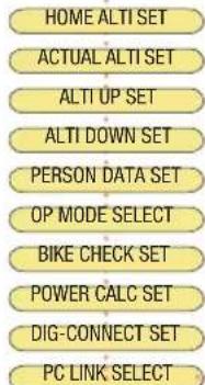
    A["LANGUAGE SELECT"] --> B["NAVIGATOR SET"]
    B --> C["WHEELSIZE SET"]
    C --> D["WHEELSIZE CHANGE"]
    D --> E["CLOCK SET"]
    E --> F["ALARM SET"]
    F --> G["TIMER SETTINGS"]
    G --> H["ODOMETER SET"]
    H --> I["PULSE LIMIT SETTINGS"]
    I --> J["RECOVERY SET"]



C (Once) = last step, or back one menu level (Hold) = return to start menu
M Select/confim displayed option In the highest menu level select the next menu level Page down within the menu level
In SET mode (number flashes): Reduce number Page up within the menu level
In SET mode (number fl ashes): Increase number After subsequent confirmation of a setting the computer automatically returns to operation mode.
EN
1.4. THE DISPLAY
The display of your VDO computer is comprised of three large areas.
The following information is displayed in operation mode:
* If the computer is worn as a sport watch then the temperature can be falsified by body warmth.

INSTRUCTION MANUAL
1.5. EXTENSION OPTIONS & ACCESSORIES
Extension option: You have the possibility of extending your computer with the cadence extension set
In this case the following cadence functions are available to you:
Actual cadence
Average cadence
Maximum cadence

In addition you can also get the following original VDO replacement parts from your dealer
| Designation article number | |
| Universal handlebar holder - wireless art. no. 5503 | |
| Magnet S/M for speed impulses art. no. 4410 | |
| Magnet L/XL for speed impulse art. no. 4412 | |
| Cadence magnet art. no. 4411 | |
| Speed transmitter art. no. 6602 | |
| Pulse transmitter (incl. elastic chest belt) art. no. 6605 | |
| Elastic chest belt for pulse transmitter article art. no. 6606 | |
| Replacement docking station art. no. 6609 | |
| Cadence kit art. no. 6603 | |
| Wrist band art. no. 6607 | |
| Wrist band lock art. no. 6608 | |
| Universal mount kit art. no. 6601 |
When purchasing look for the VDO Cyclecomputing original equipment logo. Only products bearing this logo are authorized by VDO Cyclecomputing for use with your computer.
2. INSTALLATION
2.1. BATTERY INSTALLATION
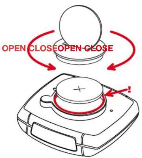
2.1.1 BATTERY INSTALLATION - COMPUTER AND SPEED/CADENCE TRANSMITTER >>> P02
step 1 Insert the battery into the computer/transmitter housing with the + pole up.
step 2 Ensure that the battery is not tilted.
step 3 Ensure that the rubber seal lies smoothly on the lid of the battery compartment.
step 4 Insert the battery compartment lid into the opening and use a coin to firmly turn the battery door to right until the stop (approximately 1/3 turn)
TIP for changing batteries: VDO recommends changing the batteries yearly to avoid undesired data loss. Thus strictly ensure that you note the entered wheel sizes as well as the previous ridden kilometers for bike 1 & bike 2, as well as the total altitude difference for bike 1, bike
EN
2, and the altitude difference walked. Reprogram this information after inserting the new batteries.
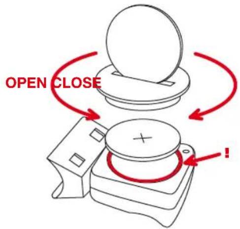
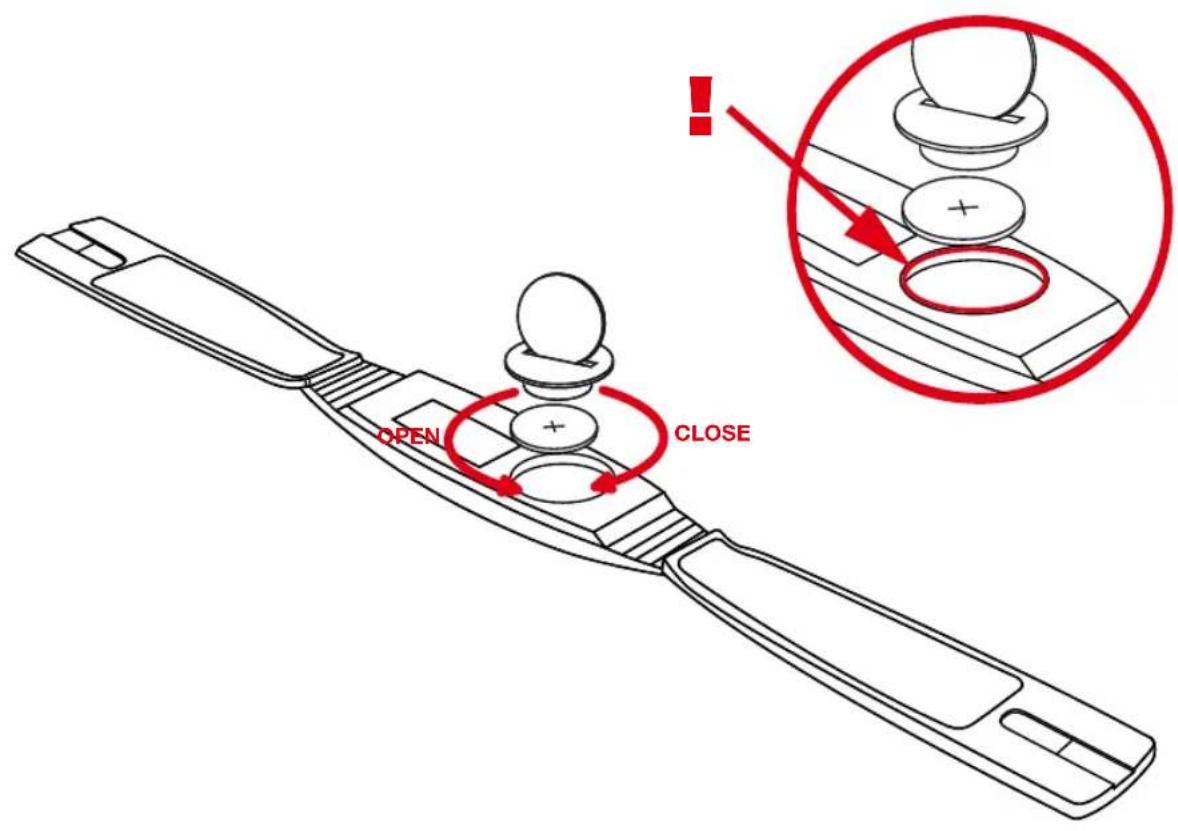
2.1.2 BATTERY INSTALLATION PULSE-CHEST BELT >>> P03
Your VDO is shipped with the battery installed in the pulse-chest belt.
Proceed as follows when later inserting a replacement battery:
step 1 Insert the battery into the chest-belt housing with the +pole up.
step 2 Ensure that the battery is not tilted.
step 3 Strictly ensure that the rubber seal lies smoothly on the battery compartment lid.
step 4 Insert the battery compartment lid into the opening and use a coin to firmly turn the battery door to right until the stop (approximately 1/3 turn)
2.2. INSTALLATION - HOLDER/COMPUTER/TRANSMITTER/MAGNET
a. Holder >>> P04/05: Your VDO computer is shipped with a universal handlebar holder.
step 1 You can mount the holder either on the handlebar or the stem. If you are installing the holder on the handlebar decide whether you want it on the right side or the left side. If installing on the stem, loosen the screws in the holder and turn the foot of the holder to stem installation. Then screw the foot firmly onto the holder again.
step 2 Route the cable ties through the provided eyes of the holder foot and pull both of them tight.
b. Computer >>> P06
The VDO twist-click system securely connects the computer to the
handlebar holder.
step 1 Insert the computer, turned to the left approximately 45 degrees (10 o'clock position) into the holder.
step 2 Twist the computer to the right until it audibly engages (clicks) in the holder system (12 o'clock position).
step 3 To remove the computer turn it to the left (do not press or pull).
c. Speed transmitter and magnet >>> P07
Mount the transmitter on the same side of the handlebar that the computer is mounted on. If you have installed the holder on the stem then we recommend mounting the transmitter on the left side.
step 1 Loosely fasten the transmitter on the fork with cable ties (do not tighten).
step 2 Place the spoke magnet on a spoke
step 3 Align the spoke magnet to the transmitter marking with a clearance of approximately 3 mm and click it together.
step 4 Align transmitter and magnet relative to each other and tighten the cable tie on the transmitter.
Please pay attention to the maximum distances:
- Maximum transmitter-computer distance = 120 cm
- Transmitter-magnet distance: 3 mm to a maximum of 10 mm
2.3. PUTTING ON THE PULSE-CHEST BELT >>> P08
step 1 First connect the one side of the pulse transmitter with the elastic strap, as shown. Press the ends of the pulse-chest belt into the plastic holder of the elastic strap
step 2 Place the pulse transmitter just below your chest and guide
INSTRUCTION MANUAL
the elastic strap over your back to the other end of the pulse transmitter
step 3 Connect the second end of the plastic strap to the pulse transmitter
step 4 Use the size adjustment of the elastic strap to adjust the chest belt to your chest size
Please note:
- Do not adjust the chest belt too loose; if it is too loose it can slip if there are jolts (e.g. when walking)
- When putting on the chest belt moisten the electrodes so that trouble-free function is also ensured when starting exercise, before contact is established through sweat.
- Range of the pulse-chest belt transmitter = 0.90 m
2.4. MOUNTING THE COMPUTER ON THE WRIST BAND >>> P09
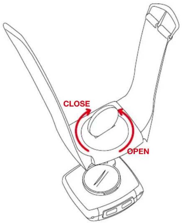
step 1 Insert the computer into the opened wrist band
step 2 Insert the lock into the wrist band holder from below
step 3 Turn the lock with a coin to tighten it
ATTENTION: Never use a screwdriver to operate the lock. This could damage the lock (if the lock should be damaged then you can get the lock as original replacement part)
After inserting the batteries we recommend that you first reset the device to factory settings to ensure that no residual data from the quality
control process remains in the computer. This puts the computer into an assured start mode.
- Press the AC button for approximately 2 seconds with a sharp object, such as a pencil
3.2. LANGUAGE SELECTION
3sec. ① Setting mode LANGUAGE SELECT
step 2 M Confirm LANGUAGE SELECT with M
step 3 ▼▲ Press the up or down button until the desired language appears
step 4 M Confirm your language selection with M
3.3. MANUAL PAIRING - INITIAL OPERATION WIRELESS SYSTEM
For initial operation of the digital wireless system manual pairing must ALWAYS be executed. Manual pairing ensures that the computer learns the coding of the transmitter you are using.
step 1 Insert the computer into the twist-click holder
step 2 Ensure that there are no ANT+Sport digital transmitters other than the transmitter you are using within a 5-meter area around the computer
Your computer will randomly select one of 128,000 codes. This ensures that signals of other transmitters are not received or processed (e.g. when riding in a group). If dashes are shown in the display, in spite of pairing, you must repeat the manual pairing process. In doing so ensure that the electrodes of the pulse transmitter belt are wet, or that the distance between the magnets and the speed/cadence transmitter is not greater than 5 mm.
ATTENTION: Your computer can save the codes of up to 5 transmitters
EN
- Speed transmitter of bike 1
- Speed transmitter of bike 2
- Cadence transmitter of bike 1 (optional)
- Cadence transmitter of bike 2 (optional)
- Pulse transmitter
3.3.1. INITIAL OPERATION - PULSE TRANSMITTER
Put the pulse transmitter belt on and moisten the electrodes (chapter 2.3)
3sec. ① Setting mode LANGUAGE SELECT
▼ ▲ Select DIG CONNECT SET
M Display DIG CONNECT
▼ ▲ Select PULSE SEARCH
M PULSE PAIRING
PAIR DONE appears in the display after several seconds if the pulse transmitter was found. Automatic return to the TRIP DIST menu. If the pulse transmitter was not found PULSE REPEAT appears. Use Ⓜ to repeat the pairing process for the pulse transmitter. For troubleshooting see chapter 17.
3sec. ① Setting mode LANGUAGE SELECT
▼ ▲ Select DIG CONNECT SET
MDisplay DIG CONNECT
Select SPEED SEARCH
M SPEED PAIRING
Now turn the front wheel (both magnet and transmitter must be already mounted)
PAIR DONE appears in the display after several seconds if the speed transmitter was found. Automatic return to the TRIP DIST menu
SPEED REPEAT appears if the speed transmitter was not found. Use M to repeat the pairing process for the speed transmitter. For troubleshooting see chapter 17.
3.3.3. INITIAL OPERATION - CADENCE TRANSMITTER (OPTIONAL EXTENSION see chapter 1.5)
3sec. 1 Setting mode LANGUAGE SELECT
▼ ▲ Select DIG CONNECT SET
M Display DIG CONNECT
▼ ▲ Select CADENCE SEARCH
M
CADENCE
PAIRING
Now turn the crank (magnet and transmitter must be already mounted) PAIR DONE appears in the display after several seconds if the cadence transmitter was found.
Automatic return to the TRIP DIST menu
If the cadence transmitter was not found CADENCE REPEAT will be displayed.
With M repeat the pairing for the cadence transmitter
For troubleshooting see chapter 17.
IMPORTANT NOTE / Re-open of transmitter search for the receive channel after interruption
If no signal is received from an already paired transmitter after 15
minutes (for example riding without chest belt for Z2 and Z3, also
PC-LINK models), the receive channel will be closed for this transmitter.
INSTRUCTION MANUAL

In this case your VDO computer will show dashes for the respective function in the display. To re-open all receive channels press the 1 and A buttons at the same time: Now your VDO computer will again receive all previously paired transmitters that are in range.
4. GENERAL SETTINGS
4.1. SETTING THE LANGUAGE
3sec. 1 Setting mode LANGUAGE SELECT
M LANGUAGE SELECT
▼▲ Select „LANGUAGE ENGLISH“
M Automatic return to TRIP DIST
Language selection done.
4.2. SETTING TIME & DATE
3 sec. ① Setting mode LANGUAGE SELECT
CLOCK SET
MSET HOUR ?CONTINUE?
Setting hours
MSET MINUTES ?CONTINUE?
Setting minutes
M SET YEAR ?CONTINUE?
Setting the year
MSET MONTH ?CONTINUE?
Setting the month
MSET DAY ?CONTINUE?
Setting the day
M CLOCK ?SET OK?
M CLOCK SET DONE
Automatic return to CLOCK
4.3. SETTING THE ALARM, ALARM CLOCK
3 sec. ① Setting mode LANGUAGE SELECT
ALARM SET
MALARM ON or ALARM OFF ( ▼ to switch on)
When the alarm clock is switched off setting mode ends automatically by M.
MSET HOUR ?CONTINUE?
▼▲ Selecting the hours value
M„SET MINUTES ?CONTINUE?
▼▲ Selecting the minutes value
M ALARM ?SET OK?
M ALARM SET DONE!
Automatic return to the operation mode for CLOCK. Setting the alarm clock done.
The alarm clock icon is now shown in the display (center bar left).
5. BICYCLE FUNCTION SETTINGS
5.1. Measuring and setting wheel size/s
In order for your VDO computer to measure correctly you must first measure the circumference of your wheel. If this value is set incorrectly then all values calculated on the basis of this value, such as speed, trip, etc. will be wrong. To use your VDO computer on two different bikes e.g. mountain bike and road bike you can enter two different wheel sizes. Measuring the wheel circumference:
step 1 Align the valve of the front wheel so that it is precisely vertical
EN
to the ground
step 2 Mark this point on the ground with a line (use chalk for example)
step 3 Push the bike one wheel rotation forward until the valve is again vertical to the ground.
step 4 Mark this point on the ground as well.
step 5 Measure the distance between the two marks. The result is your wheel circumference (=roll circumference).
step 6 Enter the wheel circumference as described below into your VDO computer.
ATTENTION: If you have selected KMH display then you must enter the wheel circumference in mm. If you have selected MPH display then enter the wheel circumference in inches. The values listed in table >>>
P10 are approximate values. These values deviate depending on brand of tire, tire height and tire tread.
Setting wheelsize:
3 sec. ① Setting mode LANGUAGE SELECT
WHEELSIZE SET
M WHEELSIZE KMH-DISPLAY or WHEELSIZE MPH-DISPLAY ( ▼ to change to mph)
MWHEELSIZE 1 ... SET SIZE ?CONTINUE?
Set wheel size 1 in mm (keep button depressed for fast run-through)
M WHEELSIZE 1 ?SET OK?
M WHEELSIZE 1 SET DONE
Automatic change to
Set wheel size 2 in mm (keep button depressed for
fast run-through)
M WHEELSIZE 2 ?SET OK?
MWHEELSIZE 2 SET DONE
Automatic return to operation mode for TRIP DIST. If you do not want to set wheel size 2 then hold Ⓐ to return to TRIP DIST operation mode.
Attention: Factory settings for bike 1 = 2155 mm and for bike 2 = 2000 mm. If you do not enter wheel sizes the computer will work with the factory settings. The values measured in this manner for speed, distance, etc. can deviate from the actual values.
5.2. CHANGING THE WHEEL SIZE
With wheel size you change the computer from bike 1 (e.g. road bike) to bike 2 (e.g. mountain bike). The computer now works with the settings for bike 2.
3 sec. ① Setting mode LANGUAGE SELECT
WHEELSIZE CHANGE
M
WHEELSIZE 1 or WHEELSIZE 2 ?SET OK?
M
Changing the wheel size
MWHEELSIZE SET DONE
Automatic return to TRIP DIST
Wheel size set done
Display of the actual wheel size in the center bar of the display, right bottom (1 or 2)
INSTRUCTION MANUAL
5.3. SETTING TOTAL KILOMETERS
You can program the total distances into your VDO computer that get lost when changing batteries or that you have previously counted with a different device. This function is available for both wheel sizes (both bikes).
Setting total KM 1 or 2
3 sec. 1 Setting mode LANGUAGE SELECT
ODOMETER SET
M ODO BIKE 1 SET or ▲ ODO BIKE 2 SET
MODO BIKE 1/2 NEXT DIGIT?
Set last digit (keep button depressed for fast run-through)
MODO BIKE 1/2 NEXT DIGIT?
Set digit (keep button depressed for long run-through) ... repeat for all digits from back to front
MODO BIKE 1/2 ?SET OK?
Set first digit (keep button depressed for fast run-through)
MODO BIKE 1/2 SET DONE
Automatic return to operation mode for ODO BIKE 1/2 menu. Set ODO BIKE 1/2 done
5.4. BIKE CHECK / SERVICE INTERVAL
Your VDO computer allows you to set the service interval to any interval for both of your bikes independently. The service check reminds you to have your bicycle serviced, like the service indicator in your car.
Set bike check bike 1 or bike 2
3 sec. ① Setting mode LANGUAGE SELECT
BIKE CHECK SET
M BIKE CHECK ON or BIKE CHECK OFF ( ▼ to switch off the bike check)
M„BIKE 1 SET or BIKE 2 SET
Set service interval in KM or m (keep button depressed for fast run-through)
MBIKE 1/2 ?SET OK?
MBIKE 1/2 SET DONE
Automatic return to operation mode for TRIP DIST
Bike check set done
If BIKE CHECK is shown in the display then you should either perform the recommended bike check yourself or have your bike checked by your dealer. Press any button. The BIKE CHECK text will disappear. After another 50 km the service interval icon (screw driver) will disappear.
6. PERSONAL SETTINGS (YOUR DATA)
IMPORTANT NOTE: The personal settings are the prerequisite for calculating maximum pulse, training zones, and calorie consumption. Ensure that you make the personal settings first so that you can fully utilize the possibilities offered by the computer. Your personal maximum pulse is an important value. You can enter this value into your VDO computer if you know it from earlier measurements (e.g. at the doctor's office or from a performance test). If you do not know it then you can select automatic calculation of your maximum pulse.
EN
WARNING: Automatic calculation is based on average values for people that are athletic and healthy. The actual value can deviate from this average value for people who have not been athletically active for some time, or who after illness, are going through a rehabilitation program. Strictly ensure that you speak with your doctor before starting to train, so that he can confirm that training would not be associated with any adverse effects.
6.1. PERSONAL SETTINGS WITH MANUAL MAX. PULSE ENTRY
IMPORTANT: A wrong entry can have adverse effects on your health. Tables providing general information cannot reliably reflect your specific training status. Strictly ensure that you speak with your doctor before entering your max. pulse manually.
3 sec. 1 Setting mode LANGUAGE SELECT
PERSON DATA SET
M
SET
AGE
?CONTINUE?
Setting age
M
SET
WEIGHT
?CONTINUE?
Setting weight
MSET SEX ?CONTINUE?
Setting sex (M = male, F = female)
M SET P MAX MANUAL ( ▲ to go to manual
max. pulse calculation)
MPULSE MAX ?SET OK?
Setting the maximum pulse
MPERSON DATA ?SET OK?
MPERSON DATA SET DONE
Automatic return to operation mode for the selected timer.
SET P MAX MANUAL done
6.2. PERSONAL SETTINGS WITH AUTOMATIC MAX. PULSE CALCULATION IMPORTANT: Automatic max. pulse calculation is based on tables showing general information that cannot reliably reflect your specific training status. Before you start training strictly ensure that you speak with your doctor.
3 sec. ① Setting mode LANGUAGE SELECT
PERSON DATA SET
M
SET
AGE
?CONTINUE?
Setting age
M
SET
WEIGHT
?CONTINUE?
Setting weight
MSET SEX ?CONTINUE?
Setting sex (M = male, F = female)
MSET PMAX MANUAL (go to autom.)
SET P MAX AUTOCALC
M Auto VALUE will be displayed for 2 seconds
PULSE MAX CALC DONE
M PERSON DATA ?SET OK?
MPERSON DATA SET DONE
Automatic return to operation mode for the selected timer. Set HF max manually done
INSTRUCTION MANUAL
7.PULSE FUNCTION SETTINGS
The pulse functions of your VDO computer are based on the specification of three training programs each with 3 training ranges.
Limit 1 = program 1: for recovery training (high 70%, low 50% of max. pulse)
Limit 2 = program 2: program for endurance training (high 80%, low 70% of max. pulse)
Limit 3 = program 3: Training program for development ranges (high 95%, low 80% of max. pulse)
For automatic calculation of the training programs ensure that values are calculated that correspond to your personal settings (chapter 6). Also pay attention to the warning in chapter 6. All information concerning use and starting of pulse recording is provided in chapter 14.1-14.4.
7.1. AUTOMATIC CALCULATION OF PULSE LIMIT VALUES
Automatic calculation of pulse limit values functions only after entry of the personal data (chapter 6).
Your computer automatically assigns the following limit values to the three training programs
Limit 1 = HIGH 70%, LOW 50% of maximum pulse
Limit 2 = HIGH 80%, LOW 70% of maximum pulse
Limit 3 = HIGH 95%, LOW 80% of maximum pulse
3 sec. ① Setting mode LANGUAGE SELECT
PULSE LIMIT SETTINGS
MPULSE LIMIT ?SET?
M
PULSE
LIMIT
AUTOCALC
MAUTO LIMIT 1 HIGH...LOW
Shows AUTO LIMIT 1 for 3 sec., go to AUTO LIMIT 2
AUTO LIMIT 2 HIGH...LOW
Shows AUTO LIMIT 2 for 3 sec., go to AUTO LIMIT 3
AUTO LIMIT 3 HIGH...LOW
Shows AUTO LIMIT 3 for 3 sec.
Automatic return to operation mode for the selected timer.
7.2. MANUAL ENTRY OF PULSE LIMIT VALUES
3 sec. ① Setting mode LANGUAGE SELECT
PULSE LIMIT SETTINGS
MPULSE LIMIT ?SET?
M
PULSE
LIMIT
AUTOCALC
PULSE LIMIT MANUAL SET
MPULSE LIMIT 1 ?SET?
▼ Select LIMIT 1/LIMIT 2/LIMIT 3
MSET HIGH 1 ?CONTINUE?
Set high limit training range 1/2/3
MSET LOW 1 ?CONTINUE?
Set low limit training range 1/2/3
M LIMIT x ?SET OK? (x = selected training range 1, 2, or 3)
M LIMIT x SET DONE (x = selected training range 1, 2, or 3)
Automatic return to the selected TIMER.
EN
7.3. SELECT TRAINING PROGRAM
3 sec. ① Setting mode LANGUAGE SELECT
PULSE LIMIT SETTINGS
MPULSE LIMIT ?SET?
PULSE LIMIT ?SELECT?
LIMIT 1 ?SELECT? or ▼ LIMIT 2 ?SELECT? or ▼
LIMIT 3 ?SELECT?
MLIMIT 1/2/3 SET DONE
Automatic return to operation mode for the selected timer. The selected training program LIMIT 1 or LIMIT 2 or LIMIT 3 is displayed in the pulse functions P. The high and low limits set for the selected program will also be displayed.
7.4. SET RECOVERY PULSE MEASUREMENT
With your VDO computer you can select the following presets for the recovery pulse measurement.
-
Recovery time: Pulse reduction within the set recovery time.
-
Recovery pulse: Duration until reaching the set recovery pulse.
a. Setting the recovery time
3 sec. ① Setting mode LANGUAGE SELECT
RECOVERY SET
M RECOV TIME SET
Set the recovery time in 30 second increments
MRECOV TIME ?SET OK?
MRECOV TIME SET DONE
Automatic return to the operation mode for RECOV TIME
Recovery time set done
b. Setting the recovery pulse
3 sec. ① Setting mode LANGUAGE SELECT
RECOVERY SET
M RECOV TIME SET
RECOV PULSE SET
Setting the recovery pulse
MRECOV PULSE ?SET OK?
MRECOV PULSE SET DONE
Automatic return to the operation mode for RECOV PULSE
Recovery pulse set done
IMPORTANT FOR THE CHANGE: In operation mode the last setting made of the settings cited above is always displayed. To change, in the settings menu confirm the desired settings as specified above.
- MEASURING THE RECOVERY PULSE/RECOVERY TIME
In the operating mode select RECOVPULSE or RECOVTIME with the
P button. To start the measurement press the buttons 1+2 at the same time. After the set recovery time elapses or after reaching the set recovery pulse the measurement will end automatically. The recovery time will be displayed in the third display line.
7.5. SETTING THE BASIC VALUES FOR POWER CALCULATION IN WATT (OPTIONAL)
IMPORTANT: Power calculation is only activated if the optional cadence extension is installed.

INSTRUCTION MANUAL
Power is calculated in WATT via a mathematical algorithm. Deviations from a real WATT measurement system are possible, particularly if there is a strong headwind or tailwind. The more precise the setting of the bicycle used, (its weight as well as your seat position), the more precise the displayed value will be.
IMPORTANT: If the cadence option is installed the WATT shows ZERO when you stop moving the pedals.
3 sec. ① Setting mode LANGUAGE SELECT
POWER CALC SET
M
BIKE
TYPE
SELECT
MROAD BIKE SELECT or ▼ MTB SELECT
M„SITTING POS SELECT
MUPRIGHT SELECT or ▼ LOW RACE SELECT
M SET WEIGHT ?SET OK? (Note: This is where the bike weight, including panniers if necessary, is entered)
Setting the weight in kg
M POWER CALC SET DONE
Automatic return to the mode for POWER WATT Set watt calculation done
8. ALTITUDE FUNCTION SETTINGS
The altitude measurement function of your VDO computer is based on barometric pressure. The opening necessary in this regard on the underside of the device should not be manipulated (never poke a sharp object into this opening). Note the following for precise altitude measurement:
a. Prior to starting each trip you must enter a start altitude into your computer.
If you always start your trip from the same location then you only need to enter the start altitude once.
If the start location changes then you must set the new start altitude.
b. Your VDO computer records barometric pressure changes (e.g. due to weather changes) in sleep mode as a change in actual altitude. If for example your bicycle is in the cellar for two days and the air pressure changes due to weather, then your computer will show a changed actual altitude. This is why the home altitude must be recalculated prior to starting each trip.
c. For longer trips the actual altitude should be readjusted at certain points (e.g. readjust to summit altitudes). Deviations can occur due to different weather conditions at the various points of the trip. You should make corrections so that the measurement is as accurate as possible. Tip home altitude:
You can obtain the correct information for the altitude of your home location or your usual trip starting point from your local weather bureau.
When planning trips you can find the original altitudes at certain points of your trip on special maps. These maps are available in book stores.
EN
8.1. SETTING THE HOME ALTITUDE (STARTING ALTITUDE)
3 sec. ① Setting mode LANGUAGE SELECT
HOME ALTI SET
M
Setting the home altitude
MHOME ALTI ?SET OK?
MHOME ALTI SET DONE
Automatic return to the operation mode for ALTI UP. The set home altitude will be displayed as actual altitude. Home altitude set done
Re-calibrating the air pressure to home altitude. Important: Prior to each trip the actual measured pressure must be calculated back to the set home altitude = re-calibrate. Short-cut press the A button for 4 seconds.
8.2. SETTING THE ACTUAL ALTITUDE
3 sec. ① Setting mode LANGUAGE SELECT
ACTUAL ALTI SET
Setting the actual altitude
MACTUAL ALTI ?SET OK?
MACTUAL ALTI SET DONE
Automatic return to the operation mode for ALTI UP. Actual altitude set done
8.3. ANNUAL UPHILL ALTITUDE GAIN BIKE 1 AND BIKE 2 AND WALK MODE
Your VDO computer accumulates values for the meters in altitude for the uphill gain covered separately for:
- Bike 1
- Bike 2
- Walk mode (see chapter 10 for selection)
These values can be programmed in, if for example you want to transfer the values from an older device, or if the values have been deleted when changing batteries.
Setting the annual uphill gain in altitude
3 sec. ① Setting mode LANGUAGE SELECT
ALTI UP SET
M ALTI UP 1 SET (for bike 2 or walking
ALTI UP 2 SET / WALK UP SET)
M ALTI UP 1 NEXT DIGIT/ ALTI UP 2 NEXT DIGIT / WALK UP NEXT DIGIT
Set last digit (keep button depressed for fast run-through)
M... repeat for all digits from back to front
M ALTI UP 1 ?SET OK? / ALTI UP 2 ?SET OK? / WALK UP ?SET OK?
Setting the first digit
M ALTI UP 1 SET DONE / ALTI UP 2 SET DONE / WALK UP SET DONE
Automatic return to the operation mode for TOTAL UP. Annual uphill altitude gain set done.
8.4. ANNUAL DOWNHILL ALTITUDE LOSS BIKE 1 AND BIKE 2 AND WALK MODE
Setting the annual downhill altitude loss
3 sec. ① Setting mode LANGUAGE SELECT
INSTRUCTION MANUAL
ALTI DOWN SET
M ALTI DOWN 1 SET (for bike 2 or
walking ▲ ALTI DOWN 2 SET / WALK DOWN SET)
M ALTI DOWN 1 NEXT DIGIT / ALTI DOWN 2 NEXT DIGIT / WALK DOWN NEXT DIGIT
Set last digit (keep button depressed for fast run-through)
M... repeat for all digits from back to front
M ALTI DOWN 1 ?SET OK? / ALTI DOWN 2 ?SET OK? / WALK DOWN ?SET OK?
Setting the first digit
M ALTI DOWN 1 SET DONE / ALTI DOWN 2 SET DONE / WALK DOWN SET DONE
Automatic return to the operation mode for TOTAL DOWN Annual downhill altitude loss set done
9. RESET MODE
In reset mode of your VDO computer you reset the saved ride data of the bicycle computer. You can also reset the computer to the factory settings
9.1 TRIP DATA
ATTENTION: When resetting the trip data the following day trip data will be deleted:
- Daily distance
- Trip ride time
- Average speed
-
Maximum speed
-
Uphill altitude gain
- Downhill distance
- Maximum trip altitude
- Average ascending gradient
- Maximum ascending gradient
- Downhill altitude loss
- Downhill distance
- Average descending gradient
- Maximum descending gradient
If the cadence option is mounted then the cadence data will also be reset.
- Average cadence
- Maximum cadence
3 sec. 2 TRIP DATA ?RESET?
MTRIP DATA ?RESET? < flashing
MTRIP DATA RESET DONE
Automatic return to operation mode for TRIP DIST
9.2 RESET TOTAL RIDE TIME
ATTENTION: When resetting total ride time the following data is deleted:
- Total ride time
- Total ride time bike 1
- Total ride time bike 2
3 sec. 2 TRIP DATA ?RESET?
TOTAL TIME ?RESET?
M TOTAL TIME ?RESET? <> flashing
M TOTAL TIME RESET DONE?
EN
Automatic return to the operation mode for TOTAL TIME Reset total time done
9.3. RESETTING THE TOTAL DISTANCE METER
ATTENTION: When resetting the total distance the following data is deleted:
- Total distance
- Total distance bike 1
- Total distance bike 2
3 sec. 2 TRIP DATA ?RESET?
ODOTOTAL ?RESET?
MODOTOTAL ?RESET? < flashing
MODOTOTAL RESET DONE
Automatic return to the operation mode for ODOTOTAL Odototal reset done
9.4. RESETTING THE NAVIGATOR
Please see the detailed description of Navigator functions in chapter
12.1.-12.2. There you will learn more about use of this reset
3 sec. 2 TRIP DATA ?RESET?
▼ ▲ NAVIGATOR ?RESET?
M NAVIGATOR ?RESET? <> flashes
M NAVIGATOR RESET DONE
Automatic return to the operation mode for NAVIGATOR Navigator reset done
9.5. RESETTING TO FACTORY SETTINGS
WARNING: When resetting to factory settings all ride data and all computer settings will be reset, including the personal data. Only perform this reset if a software malfunction occurs or if your computer can no longer be operated.
step 1 Use a sharp pencil
step 2 Press the AC button on the back of the computer for 2 sec Reset to factory settings done.
10. OPERATION MODE SELECTION
Your VDO computer uses different measuring and analysis programs for different sport types. Certain functions are not available depending on the selected mode. For this reason you must select one of the following modes prior to starting your exercise:
- Cycle mode ⊗
- Walk mode 📄 (also for jogging, running, Nordic walking, inline skating)
Select operation mode:
3 sec. ① Setting mode LANGUAGE SELECT
OP MODE SELECT
M CYCLE MODE ?SET OK?
▼ to change to WALK MODE ?SET OK?
M Automatic return to the operation mode for TRIP DIST (in cycle mode), or ALTI UP (in walk mode)
INSTRUCTION MANUAL
11. OPERATION MODE
11.1. An overview of mode functions is provided in section 1.3.1.
11.2 FAST PAIRING after transmission interruption
If no signal is received from one of your already paired transmitters for more than 15 minutes (e.g. cycling without pulse-chest belt, magnet moved unintentionally) the receive channel for this transmitter will be closed. In this case your VDO computer will show dashes for the respective function in the display. To re-open all receive channels press the 1 and A buttons at the same time:

In this case your VDO computer will then receive all paired transmitters that are in range. See also chapter 15 Sleep mode
11.3. GETTING STARTED - quick overview
Functions/operation/reset/max values
11.3.0. PERMANENT FUNCTIONS
The following functions are permanently shown in the display:
HEADER
- Actual altitude
- Actual temperature
- Actual ascending gradient in percent ! Not in walk mode !
CENTER BAR
- Heart rate receive icon if the pulse transmitter belt is worn
- Beeper icon if the beeper is switched on
- Stopwatch icon if the timing function is running
-
Actual heart rate
-
Actual speed: Maximum value 120 km/h or mph (! not in walk mode !)
- Comparison of actual speed to average speed ▲ = above, ▼ below (! not in walk mode !)
- Selected wheel size 1 or 2
- REC for ongoing recording
FOOTER
- Shows selected information and corresponding value
ALTITUDE FUNCTIONS (button A)
Re-calibrating the air pressure to home altitude. Short-cut press the A button for 4 seconds.

11.3.1. ALTI UP = uphill altitude gain for the actual trip
Display A ALTI UP
Reset: 3 sec. 2 TRIP DATA ?RESET?
M TRIP DATA ?RESET? <> flashing
MTRIP DATA RESET DONE
Automatic return to operation mode for TRIP DIST
11.3.2. ⊗ DIST UP = uphill distance of the actual trip
Display A DIST UP
Reset: 3 sec. 2 TRIP DATA ?RESET? M TRIP DATA ?RESET? <> flashing
MTRIP DATA RESET DONE
This resets all data of the functions marked by ●
Automatic return to operation mode for TRIP DIST
EN
Note: The minimum altitude change for the correct distance measurement must be 1 m
11.3.3. TRIP MAX = maximum altitude of the actual trip
Display A TRIP MAX
Reset: 3 sec. 2 TRIP DATA ?RESET?
M TRIP DATA ?RESET? < flashing
MTRIP DATA RESET DONE
This resets all data of the functions marked by ●
Automatic return to operation mode for TRIP DIST
11.3.4. AVG CLIMB = average climb of the actual trip in percent
Display: A „AVG CLIMB
Reset: 3 sec. 2 „TRIP DATA ?RESET?
M TRIP DATA ?RESET? < flashing
MTRIP DATA RESET DONE
This resets all data of the functions marked by ●
Automatic return to operation mode for TRIP DIST
11.3.5. ⊗ MAX CLIMB = maximum climb of the actual trip in percent
Display A MAX CLIMB
Reset: 3 sec. 2 TRIP DATA ?RESET?
M TRIP DATA ?RESET? < flashing
MTRIP DATA RESET DONE
This resets all data of the functions marked by ●
Automatic return to operation mode for TRIP DIST
11.3.6. Ⓧ TOTAL UP = total uphill altitude gain Bike 1 and Bike 2
Display A „Tot 1/2 HM UP“ (walk mode TOTAL UP)
11.3.7. ALTI MAX = maximum altitude Bike 1 and Bike 2
Display A „Total Max 1/2“ (walk mode ALTI MAX)
11.3.8. Ⓧ ALTI DOWN = downhill altitude loss of the actual trip
Display A ALTI DOWN
Reset: 3 sec. ② TRIP DATA ?RESET?
M TRIP DATA ?RESET? < flashing
MTRIP DATA RESET DONE
This resets all data of the functions marked by ●
Automatic return to operation mode for TRIP DIST
11.3.9. DIST DOWN = downhill distance of the actual trip
Display A DIST DOWN
Reset: 3 sec. 2 TRIP DATA ?RESET?
M TRIP DATA ?RESET? < flashing
MTRIP DATA RESET DONE
This resets all data of the functions marked by ●
Automatic return to operation mode for TRIP DIST
Note: The minimum altitude change for the correct distance measurement must be 1 m
INSTRUCTION MANUAL
11.3.10. AVG DOWN = average downhill slope in percent
Display A „Dschn down“
Reset: 3 sec. ② TRIP DATA ?RESET?
M TRIP DATA ?RESET? <> flashing
MTRIP DATA RESET DONE
This resets all data of the functions marked by ●
Automatic return to operation mode for TRIP DIST
11.3.11. MAX DOWN = maximum downhill gradient in percent
Display A MAX DOWN
Reset: 3 sec. 2 TRIP DATA ?RESET?
TRIP DATA ?RESET? <> flashing
MTRIP DATA RESET DONE
This resets all data of the functions marked by ●
Automatic return to operation mode for TRIP DIST
11.3.12. Ⓧ TOTAL DOWN = total downhill altitude bike 1 and bike 2
Display A TOTAL DOWN (walk mode TOTAL DOWN)
BICYCLE FUNCTIONS (button 1)
With the exception of the CLOCK function NO bicycle functions are available in walk mode. The 1 button has no function in walk mode.
11.3.13. ⊗ TRIP DISTANCE = distance of the actual trip
Display 1 TRIP DISTANCE
Reset: 3 sec. ② TRIP DATA ?RESET?
TRIP DATA ?RESET? <> flashing
MTRIP DATA RESET DONE
This resets all data of the functions marked by ●
Automatic return to operation mode for TRIP DIST
Maximum value: 999.99 KM or MI. If this number is overranged then
TRIP DISTANCE, RIDE TIME, and AVERAGE SPEED will be set to ZERO.
11.3.14. ⊗ RIDE TIME = ride time of the actual trip
With auto start/stop function: Starts automatically when you start off and stops automatically when you stop
Display 1 RIDE TIME
Reset: 3 sec. ② TRIP DATA ?RESET?
M TRIP DATA ?RESET? <> flashing
MTRIP DATA RESET DONE

Automatic return to operation mode for TRIP DIST
Maximum value 24 hours. If this number is overranged then TRIP
DISTANCE, RIDE TIME, and AVERAGE SPEED will be reset to ZERO.
11.3.15. ⊗ AVG SPEED = average speed of the actual trip
Display 1 AVG SPEED
Reset: 3 sec. ② TRIP DATA ?RESET?
M TRIP DATA ?RESET? < flashing
MTRIP DATA RESET DONE
Automatic return to operation mode for TRIP DIST
Accuracy: 2 decimal places. If DAILY DISTANCE or RIDE TIME are
overranged this value will be reset to ZERO
EN
11.3.16. ⊗ MAX SPEED = maximum speed of the actual trip
Display
1
MAX
SPEED
Reset: 3 sec.
2
TRIP DATA ?RESET?
M TRIP DATA ?RESET? <> flashing
MTRIP DATA RESET DONE
Automatic return to operation mode for TRIP DIST
Maximum value 120 km/h or mph. Accuracy 2 decimal places. Not suitable for motorcycles.
OPTION ONLY WITH CADENCE EXTENSION
11.T1. ⊗ CADENCE = actual cadence in crank revolutions per minute
Display
1
CADENCE
Reset: 3 sec.
2
TRIP DATA ?RESET?
TRIP DATA ?RESET? <> flashing
MTRIP DATA RESET DONE
-
Automatic return to operation mode for TRIP DIST
Note: Pedaling backward can result in unrealistically high values
11.T2. ⊗ CAD AVG = average cadence of the actual trip
Display
1
CAD AVG
Reset: 3 sec
2
TRIP DATA ?RESET?
M TRIP DATA ?RESET? <> flashing
MTRIP DATA RESET DONE
Automatic return to operation mode for TRIP DIST
11.T3. ⊗ CAD MAX = maximum cadence of the actual trip
Display
1
CAD MAX
Reset: 3 sec.
2
TRIP DATA ?RESET?
M TRIP DATA ?RESET? <> flashing
MTRIP DATA RESET DONE
-
Automatic return to operation mode for TRIP DIST
BICYCLE FUNCTIONS (button 2)
IMPORTANT NOTE: NO bicycle functions except the CLOCK function are available in walk mode. The 2 button in walk mode automatically shows the actual time.
11.3.17. CLOCK
Setting, see chapter 4.2. (Either in 12h or 24h format; in 12h format am/pm will be shown as well)
Display
2
CLOCK
11.3.18. Ⓧ NAVIGATOR
Setting, use, see chapter 12.1.-12.2.
Display
2
NAVIGATOR
Reset: 3 sec.
2 TRIP
ATA ?RESET?
▼
NAVIGATOR ?RESET?
M
NAVIGATOR ?RESET? < flashes
M NAVIGATOR RESET DONE
11.3.19. ⊗ ODO BIKE 1 = total distance bike 1
Shows the sum of all distances ridden with bike 1 in km or mi (automatic conversion of all values when converting to mi)
Display
2 ODO BIKE 1
Maximum value: 99,999 km or mi
INSTRUCTION MANUAL
11.3.20. ⊗ ODO BIKE 2 = total distance bike 2
Shows the total of all distances ridden with bike 2 in km or mi (automatic conversion of all values when switching to mi)
Display 2 ODO BIKE 2
Maximum value: 99,999 km or mi
11.3.21. ⊗ ODOTOTAL = total distance bike 1 and bike 2
Shows the total of all distances ridden with bike 1 and bike 2 in km or mi (automatic conversion of all values when switching to mi)
Display 2 ODOTOTAL
Maximum value 199,999 km or mi
11.3.22. ⊗ TIME BIKE 1 = total time bike 1
Shows the total time of all day trips ridden with bike 1 in hhh:mm
Display 2 TIME BIKE 1
Maximum value 999:59 hhh:mm
11.3.23. ⊗ TIME BIKE 2 = total ride time bike 2
Shows the total time of all day trips ridden with Bike 2 in hhh:mm
Display 2 TIME BIKE 2
Maximum value 999:59 hhh:mm
11.3.24. TOTAL TIME = total ride time bike 1 and bike 2
Shows the total time of all day trips ridden with bike 1 and bike 2 in hhhh:mm
Display 2 TOTAL TIME
Maximum value: 1999:59 hhhh:mm
HEART RATE FUNCTIONS (button P)
PLEASE NOTE: All heart rate functions with the exception of „actual heart rate“ display require a running stopwatch or a running timer.
11.3.25. STOPWATCH = manual stopwatch
Prerequisite: Only after selecting stopwatch, chapter 13.1.
Display P STOPWATCH
Start measuring STW Press
Stop measuring STW Press
Display pulse data Ⓟ LIMIT LO HI (values run sequentially, automatically in 2 second rhythm)
Reset: STW Press button for 4 sec.
Compare chapter 14. Training with recording of the residence times in the pulse ranges
11.3.26. ✉ TIMER = timer 1 / timer 2 / timer 1+2
Prerequisite: Only after selecting timer, chapter.13.1.
Display Start measuring P STW Press
End of measurement Automatic after timer period elapses (or number of sequences for timer 1+2), beeper signal
Display pulse data Ⓟ LIMIT LO HI (values run sequentially, automatically in 2 second rhythm)
EN
Reset: STW Press button for 4 sec.
Compare chapter 14. Training with recording of the residence times in the pulse ranges
11.3.27. Ⓧ COUNTDOWN = countdown timer
Prerequisite: Only after selection of countdown timer, chapter 13.1.
Display Start measuring P STW Press
End of measurement Automatic after elapse of count-down, beeper signal
Display pulse data Ⓟ LIMIT LO HI (values run sequentially, automatically in 2 second rhythm)
Reset: STW Press button for 4 sec.
Compare Chapter 14.2. Training with the countdown timer
11.3.28. ⊕ LAP-TIMER = lap timer
Prerequisite: Only after selection of lap timer, Chapter 13.1.
Display Start measuring P STW Press
Go to next lap A+P Press buttons at the same time
End/pause measurement STW Press Display lap data P LAP REC
STW Go to the next lap data Reset: STW Press button for 4 sec.
Compare Chapter 14.4. Training with the countdown timer.
11.3.29. AVG PULSE = average pulse of the actual timing period Prerequisite: Only with running or stopped and not deleted stopwatch/ timer/countdown/lap timer function
Displaying the informatio P AVG PULSE Reset: STW Press button for 4 sec.
11.3.30. Ⓧ MAX PULSE = maximum pulse of the actual timing period
Prerequisite: Capture only with running or stopped and not deleted stopwatch/timer/countdown/lap timer function
Displaying the information ☐ MAX PULSE Reset: STW Press button for 4 sec.
11.3.31. Ⓧ PULSE MAX % = pulse as a percentage of personal maximum pulse
Prerequisite: Only with running or stopped and not deleted capture of stopwatch/timer/countdown/lap timer (STW)
Displaying the information P PULSE MAX % Reset: STW Press STW button for 4 sec.
11.3.32. Ⓧ LIMIT LO HI = residence times in the pulse ranges Prerequisite: Only with running or stopped and not deleted capture of stopwatch/timer/countdown/lap timer
Only if personal data have been entered, chapter 7.2.. Always based on selected training program (limit 1, 2, or 3), chapter 7.3.
Displaying the information P LIMIT LO HI (values run sequentially in 2 second rhythm)
Reset: STW Press button for 4 sec.
INSTRUCTION MANUAL
11.3.33. RECOV TIME or RECOV PULSE = recovery time and recovery pulse measurement
Prerequisite: Only if recovery time/recovery pulse is defined, chapter 7.2
Starting the measurement 1+2 press simultaneously Displaying the information P RECOV TIME or RECOV PULSE
Reset: STW Press button for 4 sec.
11.3.34. Ⓧ CALORIE = calorie consumption of the actual timing period
Prerequisite:
Only with running or stopped and not deleted stopwatch/timer/countdown/lap timer function
Only if personal data have been entered, chapter 7.2.
Displaying the information P CALORIE
Reset: STW Press button for 4 sec.
11.3.35 ⊗ POWER WATT = actual power in watt (optional)
Prerequisite: Only if personal data have been entered, chapter 7.2.
Displaying the information P POWER WATT
IMPORTANT: Only functions with installed cadence extension. If the cadence option is installed the power display shows ZERO when the pedals are not moving.
12. RIDING WITH THE NAVIGATOR
With the VDO Navigator you can complete trips according to Roadbooks (e.g. Moser Guide). Roadbooks are offered by many publishing houses for fantastic trips (for road bikes as well as mountain bikes) by many publishing houses. Taking a specified trip is facilitated thanks to the detailed km description of certain orientation points.
Note: This function is not available in walk mode.
The VDO Navigator is an independent km or mi counter and works in the following modes:
a. Counting down: To display the distance remaining to the next orientation point
b. Counting up: To display the distance covered since the last orientation point
Note: The Navigator always runs automatically even if you have not set it.
The Navigator km status can be set/changed at any point desired. Thus you can start in the middle of a trip or execute a km correction if you took a wrong turn.
12.1. SELECTING NAVIGATOR MODE
3 sec. ① Setting mode LANGUAGE SELECT
▼ ▲ NAVIGATOR SET
M NAVIGATOR FORWARD ( ▼ to go to NAVIGATOR BACKWARD)
M NAVIGATOR NEXT DIGIT
Set last digit (keep button depressed for fast run-
EN
through)
M, NAVIGATOR NEXT DIGIT
... repeat for all digits from back to front
M NAVIGATOR ?SET OK?
Set first digit (keep button depressed for fast run-through)
M NAVIGATOR SET DONE
Automatic return to the operation mode for NAVIGATOR
12.2. RESETTING THE NAVIGATOR AT THE ORIENTATION POINT
3 sec. 2 TRIP DATA ?RESET?
▼ ▲ NAVIGATOR ?RESET?
M NAVIGATOR ?RESET? <> flashes
M NAVIGATOR RESET DONE
Automatic return to the operation mode for NAVIGATOR
Navigator reset done
- THE TIMING FUNCTIONS
The following settings are of particular importance when using the pulse functions (chapter 14).
Your VDO computer has 6 different timing functions. If one of the timing functions is running the TIMING indicator icon @will always be flashing in the left part of the display. Moreover the residence times in the training ranges are captured for each running timing function (see chapter Kap. 14). The setting range/measuring range for all timing functions is 0:00:00 h to 24:00:00 h
TIMER 1: You can program a time e.g. for interval training. TIMER 1 counts from zero forward. At the end of TIMER 1 there is a single beep. Timer 1 only functions if you have set a time. If you have forgotten to set a time your VDO computer displays TIMER ERROR
TIMER 2: You can program a time, e.g. for the rest phase in an interval training. TIMER 2 counts from zero forward. At the end of TIMER 2 there are two beeps. Timer 2 only functions if you have set a time. If you have forgotten to set a time your VDO computer displays TIMER ERROR
TIMER 1+2 runs until you stop these functions. Timers 1 + 2 only function if you have set a time. If you have forgotten to set a time your VDO computer displays TIMER ERROR.
COUNTDOWN: You can program a time, the timer will count backwards from this time. At the end of the COUNTDOWN time there is a single beep. Countdown only functions if you have set a time. If you have forgotten to set a time your VDO computer will display COUNTDOWN ERROR.
COUNT ERROR DOWN
LAP TIMER: Start Lap Timer with STW. Start next Lap with P + A at the same time at any point of the training unit. The following values will be saved:
INSTRUCTION MANUAL
- Duration of the lap
- Average heart rate on the lap
- Average speed on the lap
The lap values can be called at any time if time measurement is stopped.
STOPWATCH: With the manual stopwatch you can manually capture the plus values of training units.
13.1. SELECTING THE TIMING FUNCTION
3 sec. ① Setting mode LANGUAGE SELECT
TIMER SETTINGS
M
TIMER
?SELECT?
Select M TIMER 1 ?SELECT?
Timer ▼ TIMER 2 ?SELECT?
☑ TIMER 1 + 2 ?SELECT ? >>> Query repeats TIMER 1 + 2 REPEATS ?SELECT?
COUNTDOWN ?SELECT?
LAP TIMER ?SELECT?
STOP WATCH ?SELECT?
M Confirm selection SET DONE
If you have not yet set any values for timer 1, timer 2, timer 1 +2, or countdown, then your VDO computer will now show ERROR in the display. In this case proceed as explained in the following chapter 13.2 Setting the timer.
13.2. SETTING THE TIMER (when selecting timer 1 or timer 2 or timer 1+2)
Setting times for timer 1/timer 2
3 sec. ① Setting mode LANGUAGE SELECT
TIMER SETTINGS
M
TIMER
?SELECT?
TIMER ?SET?
M TIMER 1 ?SET?
TIMER 2 ?SET?
Select M TIMER ?SET?
M SET HOUR ?CONTINUE?
Setting hours (keep button depressed for fast run-through)
M SET MINUTES ?CONTINUE?
Setting minutes (keep button depressed for fast run-through)
M SET SECONDS ?CONTINUE?
Setting seconds (keep button depressed for fast run-through)
M TIMER ?SET OK?
M TIMER SET DONE
Automatic return to the operation mode for TIMER 1/2. If you have not yet set any values for timer 1, and/or timer 2, then your VDO computer will now show ERROR in the display.
EN
13.3. SETTING TIMER 1 + 2 REPEATS (when selecting timer 1 + 2)
3 sec. ① Setting mode LANGUAGE SELECT
TIMER SETTINGS

TIMER
?SELECT?
TIMER 1 ?SELECT?
TIMER 1 + 2 ?SELECT?
MTIMER 1+2 REPEATS ?SELECT?
Setting the number of repeats (keep button depressed for fast run-through)
M TIMER 1+2 ?SET OK?
MTIMER 1+2 SET DONE
Automatic return to the operation mode for TIMER 1/2. If you have not yet set any values for timer 1, and/or timer 2, then your VDO computer will now show ERROR in the display.
13.4 SETTING THE COUNTDOWN (when selecting countdown timer)
3 sec. 1 Setting mode LANGUAGE SELECT
TIMER SETTINGS

TIMER
?SELECT?
TIMER ?SET?
M TIMER 1 ?SET?
COUNTDOWN ?SET?
MSET HOUR ?CONTINUE?
Setting hours (keep button depressed for fast run-through)
MSET MINUTES ?CONTINUE?
Setting minutes (keep button depressed for fast run-through)
MSET SECONDS ?CONTINUE?
Setting seconds (keep button depressed for fast run-through)
MCOUNTDOWN ?SET OK?
M COUNTDOWN SET DONE
Automatic return to the operation mode for COUNTDOWN If you have not yet set any values for countdown, then your VDO computer will now show ERROR in the display.
13.5. LAP-TIMER
The LAP timer must first be started with the STW button. To save the LAP data press buttons P + A at the same time on the desired points of the training unit. In this process the following values will be saved:
- Duration of the lap
- Average heart rate on the lap
- Average speed on the lap
The lap values can be called at any time if time measurement is stopped.
13.6. STOPWATCH
Use of the stopwatch does not require any previous setting. After preselect (see chapter 13.1), it can be stopped or started at any time with stw.
INSTRUCTION MANUAL
14. TRAINING CONTROL WITH THE PULSE FUNCTIONS
See chapter 13 for information on making the settings. For focused training control it is necessary to keep the pulse in certain ranges through specific stress, see chapter 7.2. The different training programs are defined by a low limit and high limit. The pulse range between the two values is usually the target range for your training. After determining the pulse ranges (automatically or manually) your VDO computer records the residency period in the target range as well as the times above and below the target range. For real-time monitoring your VDO computer indicates when you leave the target range via an acoustic signal, if you have set this function beforehand (see chapter 13.1)
14.1. TRAINING WITH THE STOPWATCH
The stopwatch offers the easiest possibility for capturing pulse data. When the stopwatch is running pulse data is recorded. Interruption/continuation of the recording is possible at any time with STW.
step 1 Preparing the recording:
- Set the training ranges automatically chapter 7.1, or manually chapter 7.2
- Select training program limit 1, limit 2, limit 3, chapter 7.3
- In the TIMER SETTINGS setting menu select STOPWATCH, chapter 13.2.
step 2 Beginning of the recording:
STW Start the recording
4sec. P Switch on/switch off the acoustic pulse signal
step 3 End/interruption of the recording:
STW Stop the recording
step 4 Display of the values (even during recording)
P Display data via the LIMIT LO HI pulse menu (display automatically shows the times for the three ranges in %)
- Time above the high limit
- Time between the limit values
- Time under the low limit
step 5 Deleting recorded data
4sec. STW
TIP: At the end of the training unit measure the recovery time or the recovery pulse to determine your training status. See 7.4. Recovery time and recovery pulse
Note: All bicycle altitude and pulse function can also be called up during timer operation via the 1 2 A P buttons.
14.2. TRAINING WITH TIMER 1 / TIMER 2 / TIMER 1+2
Independently of each other Timer 1 or timer 2 offer the possibility of integrating intervals with manual control in the training.
Timer 1: Programmable timer with forward counting, auto-repeat function, single beep after elapse of timer 1.
Timer 2: Programmable timer with forward counting. Auto-repeat function, double beep after elapse of timer 2.

EN
Combination timer 1+2:
The combination of timer 1+2 can be set optimally for interval training: Timer 1 = active phase, timer 2 = rest phase. When timer 1 elapses a single beep sounds, when timer 2 elapses a double beep sounds. For timer 1+2 you can set the number of repeats. In this case time 1+2 runs until all repeats have elapsed or the measurement is interrupted by STW.
IMPORTANT: During timer operation the residence periods of the pulse frequency in the selected training ranges is recorded (compare 13.1) step 1 Preparing the recording
- Set the training ranges automatically chapter 7.1, or manually chapter 7.2
- Select training program limit 1, limit 2, limit 3, chapter 7.3
- In the TIMER SETTINGS setting menu select the desired timer
step 2 Beginning of the recording:
STW Start the recording
4sec. P Switch on/switch off the acoustic pulse signal
step 3 End/interruption of the recording:
AUTOMATIC depending on timer selection at the end of the respective timer or at the end of all selected repeats with the combination function timer 1+2
STW Manual interruption = stop recording
step 4 Display of the values (even during recording):
P Display data via the LIMIT LO HI pulse menu (display automatically shows the times for the three ranges in %)
- Time above the high limit
- Time between the limit values
- Time under the low limit
step 5 Deleting recorded data
4sec. STW
Note: All bicycle altitude and pulse function can also be called up during timer operation via the 1 2 A P buttons.
TIP: At the end of the training unit measure the recovery time or the recovery pulse to determine your training status, see chapter 7.4. Recovery time and recovery pulse.
14.3. TRAINING WITH THE COUNTDOWN TIMER:
The countdown timer is a programmable timer with reverse counting. This is particularly well-suited for use in time trials. At the end of the COUNTDOWN time there is a single beep.
IMPORTANT: During countdown operation the residence periods of the pulse frequency in the selected training ranges are recorded (compare 13.1)
step 1 Preparing the recording:
- Set the training ranges automatically chapter 7.1, or manually chapter 7.2
- Select training program limit 1, limit 2, limit 3, chapter 7.3
- In the setting menu TIMER SETTINGS select AND set the countdown timer, chapter 13.1 and following.
INSTRUCTION MANUAL
step 2 Beginning of the recording:
STW Start the recording
4sec. P Switch on/switch off the acoustic pulse signal
step 3 End/interruption of the recording:
AUTOMATIC after the countdown time elapses
STW Manual interruption = stop recording
step 4 Display of the values (even during recording)
P Display data via the LIMIT LO HI pulse menu
(Display automatically shows the times for the three ranges in %)
- Time above the high limit
- Time between the limit values
- Time under the low limit
step 5 Deleting recorded data
4sec. STW
TIP: At the end of the training unit measure the recovery time or the recovery pulse to determine your training status, see chapter 7.4. Recovery time and recovery pulse.
Note: All bicycle altitude and pulse function can also be called up during timer operation via the 12AP buttons.
TIP: At the end of your countdown timer measure the recovery time or the recovery pulse to determine your training status. See 7.4. Recovery time and recovery pulse.
14.4. TRAINING WITH THE LAP TIMER
The lap timer of your VDO computer is designed for lap training. You can record up to 50 laps manually. In this case your computer saves the following values for each lap:
- Lap time
- Average pulse during the lap
- Average speed during the lap (IMPORTANT: no display in walk mode) With these values you have an outstanding method of analyzing the development of your performance if you always do the same laps. This could be certain mountain values or flat stretches on your training lap. The lap timer function can be set in bicycle mode and in walk mode.
Important:
- The values saved for the individual laps can only be shown in the display in recall mode after concluding the measurement.
- If the lap timer is running the residence period of the pulse frequency in the selected training ranges is recorded (compare 13.1)
step 1 Preparing the recording:
- Set the training ranges automatically chapter 7.1, or manually chapter 7.2
- Select training program limit 1, limit 2, limit 3, chapter 7.3
- In the TIMER SETTINGS setting menu select the lap timer chapter 13.1.
step 2 Starting/changing/interrupting laps:
P Switch on/switch off the acoustic pulse signal
STW Start lap 1
EN
Press concurrently:
A
+
P End lap 1 and start lap 2 concurrently
Start next lap:
A
+
P End lap 2 and start lap 3 concurrently.
Interrupt:
STW Interrupt lap measuring (e.g. for recovery lap or break)
You can interrupt each lap as often as desired, or end the lap and record up to 50 individual laps.
step 3 Display the values (during a break or after ending the lap training).
Prerequisite: The lap timer must be stopped (STW)
P Display data via the pulse menu LAP REC
Display of values for LAP 1 (Fig. display)
Center bar left: Average pulse on the lap
Center bar right: Average speed on the lap (IMPORTANT: no display in walk mode)
Footer: Lap number and time of the lap
STW Changing the display of values for lap 2
STW Changing the display of values for lap 3
[Non-Text]
During or after lap training the pulse data can be displayed at any time: Display data via the LIMIT LO HI pulse menu (display automatically shows the times for the three ranges in %)
- Time above the high limit
- Time between the limit values
- Time under the low limit
step 5 Deleting all recorded lap data
4sec. STW
TIP: At the end of the training unit measure the recovery time or the recovery pulse to determine your training status. See 7.4. Recovery time and recovery pulse
NOTE for DATA RECORDING:
All lap data is also recorded when using DATA RECORDING (chapter 15) and is also transferred to the PC in the data transfer. With the aid of the „PC-Sport“ training software the lap data can then be displayed on the PC
15. THE DATA RECORDING FUNCTION & TRANSFER OF DATA TO THE PO
Your VDO computer is designed for recording data and transferring data to your PC. The recorded and transferred data can be analyzed on the PC. With the „PC-Sport“ software you can keep a training journal, track developments over certain periods, and specifically plan a program for getting in shape. All necessary elements for this application are included in the scope of delivery of your computer:
- Docking station with USB cable for transferring data to the PC
- CD-ROM with the PC-Sport training and analysis software
What happens when I record training units?
Your VDO computer generates a file/data record in its memory per training unit (start/stop see below). The following data is captured in this data record (after starting data recording) in a interval (10 / 20 sec.):
- All bike data (only under certain conditions in walk mode)
- All altitude data (only under certain conditions in walk mode)
INSTRUCTION MANUAL
- All pulse data (only under certain conditions in walk mode)
- Lap data if lap timer is used
- All cadence data (if the cadence kit is installe
Note:
If you are using the lap timers the lap data will have a flag. When transferring data from the computer to the PC the lap data are identified via this flag and are displayed and analyzed separately in the PC-Sport program.
IMPORTANT INFORMATION PLEASE NOTE THE FOLLOWING:
a. The storage capacity of the device is configured for a total of 100 training hours.
b. After this total time is exceeded the new data automatically overwrites the oldest data in the memory.
c. A manual delete of training data is not possible.
d. Due to the recording interval of 10 or 20 sec. there may be slight deviation between the data in your VDO computer and the data in the PC-Sport program (e.g. average pulse)
TIPP: Connect your VDO computer to your PC at regular intervals so that important data is not overwritten. Manual control/read out of the data records of the DATA RECORDING and a data delete is not possible on your VDO computer itself.
15.1. STARTING/STOPPING DATA RECORDING
You must start data recording manually:
Start data recording:
Press P1 concurrently Start of data recording REC is displayed in the center
bar

End data recording:
Press P1 concurrently Stop data recording
REC is not illuminated
What happens when I take a break?
If you take a break during DATA RECORDING, and the computer goes into SLEEP MODE after 5 minutes (chapter 16) then DATA RECORDING will be interrupted automatically. If SLEEP MODE is ended by pressing a button then DATA RECORDING will be automatically continued.
TIP: Leave your VDO computer on the handlebar holder so that sleep mode is activated and recording is interrupted automatically after 5 minutes (see chapter 16 Sleep mode).
ATTENTION: If you manually interrupt data recording, for a break for example by pressing P 1, then a new data record will be generated at restart. Even if you do a trip data reset during „DATA RECORDING“ your VDO computer will generate a new data record.
EN
15.2. TRANSFERRING DATA TO YOUR PC >>> P11
Install the PC-Sport software on your PC. Insert your VDO computer into the docking station as shown (Fig. xxx) and connect the USB cable to one of your computer's USB ports. Now start PC Sport
- Under „FILE“ select Import
- In Import select VDO series Z
Click on the Start button in the PC Sport program, then on the Z3 go to setting mode
3 sec. ① Setting mode LANGUAGE SELECT
PC LINK SELECT
M PC LINK SENDING (the data transfer is indicated in the display by changing numbers)
Now the PC receives the data of your VDO computer. Data transfer is indicated by the changing numbers in the computer's display.
NOTE: When importing the files the PC-Sport program detects which files have already been imported. If you want to import this again you must select it manually and confirm a warning query.
Now follow the instructions on saving files in the PC-Sport program.
Please see the PC Sport electronic user manual on the CD-ROM for all additional information relative to planning and analysis of training units
15.3. SELECTION OF THE RECORDING INTERVAL
Your VDO computer offers two recording intervals (10 seconds or 20 seconds) for data recording.
Interval 1: 20 seconds
Maximum recording period: 100 hours
Selection of the recording interval: Press A+2
Interval 2: 10 seconds
Maximum recording period: 50 hours
Selection of the recording interval: Press A+2
Now the recording interval that has been set is shown in the display:
DATA RECORD
INTERVAL
10 SEC
20 SEC
▼ ▲ UP/Down - changes to the other interval.
MPress M to confirm your selection.
ATTENTION: It is not possible to switch the recording interval during a recording.
INSTRUCTION MANUAL
16. SLEEP MODE
Your VDO computer has a two-stage sleep mode.
Sleep mode is activated automatically if the computer no longer receives data.
Phase 1 after 5 minutes: - The display goes into sleep mode
- DATA RECORDING is interrupted
Now the display shows temperature, time, date, and day of the week.
. After an additional 10 minutes the second phase of sleep mode will be activated, will be activated, the receiver will be switched off.
FOR WAKE UP press any button.
Description special case 1.
No speed signals (e.g. when taking a break
No cadence signals (e.g. when taking a break)
Pulse signals will continue to be received (e.g. computer on wrist)
In this case the receive channels for speed and cadence are opened for a total of 3 hours. Energy is consumed in this process.
To extend the service life of the batteries, leave your VDO computer in the handlebar holder and move out of the receive range, or take off the pulse transmitter belt.
17. TROUBLESHOOTING
Here is a list of possible errors, their causes, and what you can to correct the error:
| Problem when pairing the speed transmitter/cadence transmitter | - Check the magnet position (distance between magnet and transmitter, position of the magnet to the transmitter point on the transmitter)- Check the battery in the transmitter- Check the battery in the computer (if battery voltage is insufficient then the receiver cannot receive the signals) |
| Problem when pairing the speed transmitter/cadence transmitter | - Check the magnet position (distance between magnet and transmitter, position of the magnet to the transmitter point on the transmitter)- Check the battery in the transmitter- Check the battery in the computer (if battery voltage is insufficient then the receiver cannot receive the signals) |
EN
| Problem when pairing the pulse-chest belt | - Check the battery in the chest belt- Check the battery in the computer (if battery voltage is insufficient then the receiver cannot receive the signals) |
| No speed display - Check the magnet position(distance between magnet and transmitter, position of the magnet to the transmitter point on the transmitter)- Check the battery in the transmitter- Check the battery in the computer (if battery voltage is insufficient then the receiver cannot receive the signals) | |
| No cadence display - Check the magnet position(distance between magnet and transmitter, position of the magnet to the transmitter point on the transmitter)- Check the battery in the transmitter- Check the battery in the computer (if battery voltage is insufficient then the receiver cannot receive the signals) | |
| No speed display (dash in the display) | The receive channel for speed is switched off (a 15-minute period has elapsed without receiving a speed signal)Press buttons A + 1 at the same time |
| No cadence data (dash in the display) | The receive channel for cadence is switched off (a 15-minute period has elapsed without receiving cadence signals)Press buttons A + 1 at the same time |
INSTRUCTION MANUAL
| No pulse display (dash in the display) | The receive channel for pulse is switched off (a 15-minute period has elapsed without receiving pulse data)Press buttons A + 1 at the same time |
| No average pulse Timer has not been startedStart timer | |
| No maximum pulse Timer has not been startedStart timer | |
| No pulse percentage of the personal maximum pulse | Personal data has not been set,timer has not been started |
| No data relative to training times is in the set training ranges | Timer has not been started.Start timer |
| Calorie display does not function Personal data has not been set,timer has not been started | |
| Watt display does not function - Personal data has not been set- Watt settings have not been made- Cadence transmitter is not installed- Cadence transmitter does not function | |
| LAP data cannot be displayed/are no longer present | The LAP data have been deleted prior to LAP RECALL |
| Screwdriver is flashing on the display ↗ | Service interval for your bicycle is displayed. Take your bicycle in for service or perform the service yourself |
| Walking shoe is shown in the display (bicycle distance data is no longer displayed) ↙ | Walk mode is switched on.In walk mode certain bike functions are not available |
| The timer indicator is flashing ⚪ | A timer is still running. |
| Bell icon is displayed ▲ | An alarm is set (alarm time) |
| The LAP icon is flashing 📄 | A LAP recording is still running.End recording with the STW button |
| The REC icon is flashing 📌 | Data recording is running. All data is recorded in the computer and can be transferred later to the PC.End data recording with button P + 1 |
EN
Data download from Z3 PC-Link/Z2 PC-Link to the PC does not function
- Ensure that the computer is correctly mounted on the docking station
- Ensure that the docking station is correctly connected to the PC via USB connector
- Ensure that the PC Sport software is open
- Ensure that PC-LINK has been called and started in the computer
- Ensure that the file Import VDO series Z has been opened and started in the PC Sport program.
18. GUARANTEE CONDITIONS
VDO Cycle Parts offers a 5-year guarantee on your VDO computer, starting from date of purchase. The guarantee extends to material and manufacturing defects on the computer itself, on the docking station, on the transmitters and on the handlebar and wrist band holder. Cable and batteries, as well as other mounting materials are excluded from the guarantee.
The guarantee is only valid if the components in questions have not been opened (exception: battery compartment of the computer), if force has not been applied, and if willful damage is not present. Please keep the purchase receipt in a safe place because it must be submitted if there is a complaint. You will receive a comparable replacement device if there is a legitimate complaint.
A claim for replacement of the identical model does not exist if the model in question is no longer in production due to a model change. Please contact the dealer from whom you purchased the device for all complaints and guarantee claims. Or send your complaint directly to
Cycle Parts GmbH, Große Ahlmühle 33, D-76865 Rohrbach. We would be pleased to answer any technical questions you might have at the following hotline number:
+49-6349-9635-10.
Additional technical information is available at: http://www.vdocyclecomputing.com
In the course of further development we reserve the right to make technical changes without prior notice.
INSTRUCTION MANUAL
19. TECHNICAL SPECIFICATIONS
Computer: Approximately 49.6 x 46.6 x 16.5 mm, weight:
Approximately 45 g
Handlebar holder: Weight approximately 15 g
Speed transmitter: Weight approximately 20 g
Pulse transmitter: Weight approximately 80 g
Battery: 3V, type 2032 (computer); type 2032 (speed transmitter); type
Battery service life:
Computer: Approximately 300 hours, approximately 8000 KM (5000 M)
(speed only)
Pulse transmitter: Approximately 800 hours
Working temperature of the display: -15 °C to +60 °C
Speed range: for wheel size 2155 mm, min 3 km/h, max 120 km/h
Ride time measurement range: Up to 24:00:00 HH:MM:SS
Stopwatch measurement range: Up to 24:00:00 HH:MM:SS
Day trip measurement range: Up to 999.99 km or mi.
NAVIGATOR measurement range: Up to 999.99 km or mi.
Total KM 1 and 2 measurement range: Up to 99,999 km or mi.
Total kilometers measuring range: Up to 199,999 km or mi.
Wheel size: 100 mm minimum, 3999 mm maximum
Memory versions:
Recording capacity: 100 hours, a maximum of 100 trips at 1 hour each

Correct Disposal of This Product (Waste Electrical & Electronic Equipment)
(Applicable in the European Union and other European countries with separate collection systems) This marking shown on the product or its literature, indicates that it should not be disposed with other household wastes at the end of its working life. To prevent possible harm to the environment or human health from uncontrolled waste disposal, please separate this from other types of wastes and recycle it responsibly to promote the sustainable reuse of material resources. Household users should contact either the retailer where they purchased this product, or their local government office, for details of where and how they can take this item for environmentally safe recycling. Business users should contact their supplier and check the terms and conditions of the purchase contract. This product should not be mixed with other commercial wastes for disposal.

EU-Declaration of Conformity
We, CYCLE PARTS GmbH, Grosse Ahlmuehle 33, D-76865 Rohrbach declare under our responsibility that the products VDO Z1, Z2,Z3,Z2 PC-Link, Z3 PC-Link and all transmitters Z-CAD, Z-PULSE, Z-SENDER, Dockingstation are compliant with the essential requirements and other relevant requirements of the R&TTE Directive (1999/5/EC). The declaration of Conformity can be found at www.vdcyclecomputer.com.
NOTICE This equipment has been tested and found to comply with the limits for a Class B digital device, pursuant to Part 15 of the FCC Rules. These limits are designed to provide reasonable protection against harmful interference in a residential installation. This equipment generates, uses and can radiate radio frequency energy and, if not installed and used in accordance with the instructions, may cause harmful interference to radio communications. However, there is no guarantee that interference will not occur in a particular installation. If this equipment does cause harmful interference to radio or television reception, which can be determined by turning the
equipment off and on, the user is encouraged to try to correct the interference by one or more of the following measures:
- Reorient or relocate the cycle computer head with the receiving antenna.
- Increase the separation between your equipment and the cycle computer head with the receiving antenna.
- Consult your bicycle dealer or an experienced radio/TV technician for help.
NOTICE: This device complies with Part 15 of the FCC Rules and with RSS-210 of Industry Canada.
Operation is subject to the following two conditions:
(1) this device may not cause harmful interference, and
(2) this device must accept any interference received, including interference that may cause undesired operation.
NOTICE: This Class B digital apparatus complies with Canadian ICES-003
NOTICE: Warning: Changes or modifications made to this equipment not expressly approved by VDO Cycle Parts GmbH may void the FCC
authorization to operate this equipment
February 2008, Cycle Parts GmbH, Grosse Ahlmuehle 33, D-76865 Rohrbach, Germany
USA CDN
ADDENDUM TO USER MANUAL
FCC ID: TFO 6604
IC 5957A-6604
C€0682
Cycle Parts GmbH

NOTICE: This equipment has been tested and found to comply with the limits for a Class B digital device, pursuant to Part 15 of the FCC Rules. These limits are designed to provide reasonable protection against harmful interference in a residential installation. This equipment generates, uses and can radiate radio frequency energy and, if not installed and used in accordance with the instructions, may cause harmful interference to radio communications. However, there is no guarantee that interference will not occur in a particular installation. If this equipment does cause harmful interference to radio or television reception, which can be determined by turning the
equipment off and on, the user is encouraged to try to correct the interference by one or more of the following measures:
- Reorient or relocate the cycle computer head with the receiving antenna.
- Increase the separation between your equipment and the cycle computer head with the receiving antenna.
- Consult your bicycle dealer or an experienced radio/TV technician for help.
NOTICE: This device complies with Part 15 of the FCC Rules and with RSS-210 of Industry Canada.
Operation is subject to the following two conditions:
(1) this device may not cause harmful interference, and
(2) this device must accept any interference received, including interference that may cause undesired operation.
NOTICE: This Class B digital apparatus complies with Canadian ICES-003
NOTICE: Warning: Changes or modifications made to this equipment not expressly approved by VDO Cycle Parts GmbH may void the FCC
authorization to operate this equipment
February 2008, Cycle Parts GmbH, Grosse Ahlmuehle 33, D-76865 Rohrbach, Germany
VDO SERIES-Z
FOR RUNNING / HIKING


www.vdocyclecomputing.com
- VDO SERIES-Z
- My Settings
- Picturebook
- EN
- Congratulations
- Package contents >>> P01
- INSTRUCTION MANUAL
- TABLE OF CONTENT
- INSTALLATION
- GENERAL SETTINGS
- BICYCLE FUNCTION SETTINGS
- PERSONAL SETTINGS IMPORTANT NOTE
- 7.PULSE FUNCTION SETTINGS
- ALTITUDE FUNCTION SETTINGS
- RESET MODE
- OPERATION MODE SELECTION
- OPERATION MODE
- RIDING WITH THE NAVIGATOR
- THE TIMING FUNCTIONS
- TRAINING WITH THE PULSE FUNCTIONS
- THE DATA RECORDING FUNCTION & TRANSFER OF DATA TO THE PO
- SLEEP MODE
- TROUBLESHOOTING
- GUARANTEE CONDITIONS
- TECHNICAL SPECIFICATIONS
- 1.1.GENERAL
- SETTING MODE - use this mode to make all settings. The assignment of buttons is on the buttons
- THE DISPLAY
- EXTENSION OPTIONS & ACCESSORIES
- BATTERY INSTALLATION
- BATTERY INSTALLATION - COMPUTER AND SPEED/CADENCE TRANSMITTER >>> P02
- BATTERY INSTALLATION PULSE-CHEST BELT >>> P03
- INSTALLATION - HOLDER/COMPUTER/TRANSMITTER/MAGNET
- PUTTING ON THE PULSE-CHEST BELT >>> P08
- Please note:
- MOUNTING THE COMPUTER ON THE WRIST BAND >>> P09
- LANGUAGE SELECTION
- MANUAL PAIRING - INITIAL OPERATION WIRELESS SYSTEM
- INITIAL OPERATION - PULSE TRANSMITTER
- INITIAL OPERATION - CADENCE TRANSMITTER (OPTIONAL EXTENSION see chapter 1.5)
- CHANGING THE WHEEL SIZE
- SETTING TOTAL KILOMETERS
- BIKE CHECK / SERVICE INTERVAL
- PERSONAL SETTINGS (YOUR DATA)
- PERSONAL SETTINGS WITH MANUAL MAX. PULSE ENTRY
- AUTOMATIC CALCULATION OF PULSE LIMIT VALUES
- MANUAL ENTRY OF PULSE LIMIT VALUES
- SELECT TRAINING PROGRAM
- SET RECOVERY PULSE MEASUREMENT
- SETTING THE HOME ALTITUDE (STARTING ALTITUDE)
- SETTING THE ACTUAL ALTITUDE
- ANNUAL UPHILL ALTITUDE GAIN BIKE 1 AND BIKE 2 AND WALK MODE
- ANNUAL DOWNHILL ALTITUDE LOSS BIKE 1 AND BIKE 2 AND WALK MODE
- TRIP DATA
- RESET TOTAL RIDE TIME
- RESETTING THE TOTAL DISTANCE METER
- RESETTING THE NAVIGATOR
- RESETTING TO FACTORY SETTINGS
- HEADER
- CENTER BAR
- FOOTER
- ALTITUDE FUNCTIONS (button A)
- BICYCLE FUNCTIONS (button 1)
- OPTION ONLY WITH CADENCE EXTENSION
- BICYCLE FUNCTIONS (button 2)
- HEART RATE FUNCTIONS (button P)
- COUNT ERROR DOWN
- LAP-TIMER
- STOPWATCH
- TRAINING CONTROL WITH THE PULSE FUNCTIONS
- TRAINING WITH THE STOPWATCH
- TRAINING WITH TIMER 1 / TIMER 2 / TIMER 1+2
- TRAINING WITH THE LAP TIMER
- Important:
- step 1 Preparing the recording:
- step 2 Starting/changing/interrupting laps:
- STARTING/STOPPING DATA RECORDING
- TRANSFERRING DATA TO YOUR PC >>> P11
- SELECTION OF THE RECORDING INTERVAL
- EU-Declaration of Conformity
- USA CDN
- ADDENDUM TO USER MANUAL
Brand : VDO
Model : Z3 PC-Link
Category : Meter