
living connect - Thermostat DANFOSS - Free user manual and instructions
Find the device manual for free living connect DANFOSS in PDF.


| Product Type | Thermostat |
| Brand | Danfoss |
| Model | living connect |
| Connectivity | Wireless (Zigbee) |
| Display | LCD with backlight |
| Dimensions (H x W x D) | 80 x 80 x 25 mm |
| Weight | 150 g |
| Power Supply | 2 x AA batteries (1.5V) |
| Temperature Range | 5°C to 35°C |
| Control | Touch-sensitive buttons |
| Main Functions | Programmable schedule, remote control via app, temperature sensor, energy saving modes |
| Maintenance | Clean with dry cloth |
| Safety Features | Overheat protection, child lock |
| Spare Parts | Batteries (AA) |
| Repairability | User-replaceable batteries; other parts not user-serviceable |
| General Information | Compatible with Danfoss heating systems; adjustable temperature steps of 0.5°C |
Frequently Asked Questions - living connect DANFOSS
User questions about living connect DANFOSS
0 question about this device. Answer the ones you know or ask your own.
Ask a new question about this device
Download the instructions for your Thermostat in PDF format for free! Find your manual living connect - DANFOSS and take your electronic device back in hand. On this page are published all the documents necessary for the use of your device. living connect by DANFOSS.
USER MANUAL living connect DANFOSS
MAKING MODERN LIVING POSSIBLE
Danford
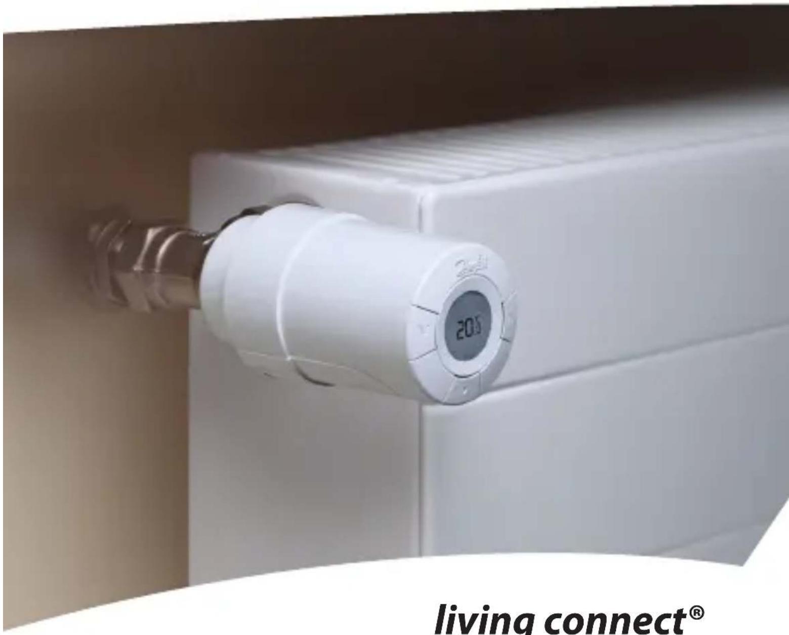
living connect® Installation and User Guide
Danfoss Heating Solutions
Thank you for buying a Danfoss product
- System overview .... 5
- Overview of display and control buttons .... 5
- Installation - step by step 6
3.1 Preparation 6
3.2 Installation of living connect ® 6
3.3 Configuring Danfoss Link™ CC 7
3.4 Connecting to Danfoss Link™ CC 9
- Technical settings....10
4.1 Reinstallation mode ....10
4.2 Testing the connection ....10
4.3 Adjustments for over/undersized radiators 11
4.4 Reset to factory settings ....11
4.5 Technical data 12
- Safety precautions ....13
- Removing living connect ® 13
- Disposal 13
User Guide ....14
1. System overview
living connect ® is an electronic radiator thermostat for homes. It is controlled by a central device called a Danfoss Link TM CC.
Danfoss Link™ CC can also control floor heating and on/off switches in the building.
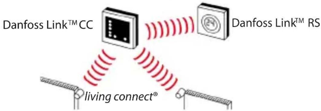
Please refer to the separate Danfoss Link TM CC and room sensor Danfoss Link TM RS manuals for more information.
living connect® uses Z-Wave wireless technology. More information is available at www.danfoss.com/living
2. Overview of display and control buttons
See page 15.
3. Installation - step by step
3.1 Preparation
living connect® is supplied with adapters for Danfoss RA valves and valves with M30X1.5 (K) connections (014G0002), two alkaline AA batteries and a 2 mm
Allen key.
Inserting the batteries
Remove the battery cover and insert the two batteries.
Ensure that the batteries are correctly inserted. [17] must flash on the display before installation, if this is not the case, see reinstallation mode page 10.

natural_image
Diagram of a battery pack with internal components and red arrows indicating flow or movement (no text or symbols)3.2 Installation of living connect®
| 1. Start by mounting the the adapter. | 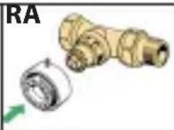 |  | |
| 2. Tighten the RA adapter using the Allen key.Tighten the K adapter by hand (max. 5 Nm). |  |  | |
| 3. Screw the thermostat onto the adapter and hand-tighten (max. 5 Nm). |  | ||
| 4. Press and hold for approx. 3 seconds to fix the thermostat. | |||
3. Installation - step by step
3.3 Configuring Danfoss Link™ CC
For practical reasons, it is recommended that the Danfoss Link TM CC is connected to a battery pack (014G0262). This makes the device mobile, and it can then easily be positioned at a distance of up to 1.5 m from each radiator thermostat that is to be added to the system.
Remove the front cover from the Danfoss Link TM CC by carefully levering it off, starting with the bottom corners. Press and hold down the setup button using a ballpoint pen for approximately three seconds to start the installation menu (the start-up phase may take several minutes).

natural_image
Close-up of a hand holding a pen next to a small electronic device (no visible text or symbols)For Help, press ? in the lower right corner.
For installation without a battery pack, please see www.danfoss.com/living.
3. Installation - step by step
UK
DE
DK
NL
- Configure the rooms in which the radiator thermostats have been installed.


- Add a new room.


- Edit or enter the room name. Press to confirm.

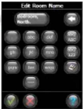
Note – a list of common room names can be found using this button
3. Installation - step by step
3.4 Connecting to Danfoss Link™ CC
Each thermostat must be connected to the Danfoss Link™ CC. This is best done by standing beside each thermostat with the Danfoss Link™ CC (connected to the recommended 014G0262 battery pack).
- The "Configure room" menu is displayed. Select "Room devices".
- Select "Add a device".
- Press Begin Registration, and then press and release on the thermostat.
- Repeat for each device.
- Once all devices have been registered and the Danfoss Link™ CC is placed in its final position, perform a network test (see separate Danfoss Link™ CC manual).




4. Technical settings
4.1 Reinstallation mode
UK
DE
DK
NL
If the thermostat has been removed from the radiator and needs to be reinstalled (after being used), it is necessary to activate installation mode to prevent damage to the thermostat.
To enter installation mode:
Press until 17 is displayed.
Press to withdraw the spindle.
171 flashes.
Reinstall the thermostat on the valve.
Press for approx. 3 seconds to exit.
Please also refer to section 6 regarding removal of the thermostat from the radiator valve.

4.2 Testing the connection
Press for at least 3 seconds until 177 is displayed.
Press until L1 is displayed.
Press to make the connection.
LI disappears when the connection is made.

If no connection can be made, the alarm and antenna symbols flash together.
Refer to "Troubleshooting" at www.danfoss.com/living

natural_image
Close-up of a circular electronic device with indicator lights and a 'Turbia' logo (no readable text or symbols beyond branding)4. Technical settings
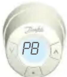
4.3 Adjustments for over/undersized radiators
The factory setting is P2.
Use P1 if the radiator appears oversized for the room.
Use P3 if it is undersized.*
Press for at least 3 seconds until m is displayed.
Press v until PB is displayed. Press
Select P1, P2 or P3 using the arrow keys, and exit using
*The frequency of P1, P2 and P3 regulation varies to compensate for radiator over/under sizing.

4.4 Reset to factory settings
Remove the battery cover and take out one battery.
Press and hold for approx. 5 seconds, while reinserting the battery.
Danfoss Link™ CC will then display "device removed". Press OK.
Note that if the thermostat is moved to another room, it is recommended it be reset to the factory default settings. The thermostat will be reset and disconnected from Danfoss Link TM CC.
4. Technical settings
4.5 Technical data
| UK |
| DE |
| DK |
| NL |
| Actuator type Electromechanical | |
| Software classification A | |
| Safety classification Type 1 | |
| Recommended use Residential | |
| Open window function Yes | |
| Synchronizing Every 5 minute | |
| Mechanical strength 70 N (max. force from valve) | |
| Maximum water temperature | 90°C |
| Movement type Linear | |
| Battery life 2 years | |
| Spindle movement 2-3 mm on the valve | |
| Maximum extension 4.5 mm | |
| Temperature sampling Measures temp. every minute | |
| Speed of adjustment 1 mm/s | |
| Power supply 2x1.5V AA alkaline, class III (SELV) | |
| Power consumption 3 mW in standby, 1.2W when active | |
| Ambient temperature | 0° to 40°C |
| Transportation temperature range | -20 to 65°C |
| Temperature setting range | 4 to 28°C |
| Size (mm) | L: 91 ∅: 51 (RA) |
| Ball pressure test | 75°C |
| Weight | 177 g |
| Transmission frequency | Wireless Z-Wave/868.42 MHz |
| IP class* | 20 |
*This thermostat should not be used in hazardous installations or in places where it will be exposed to water.
5. Safety precautions
The thermostat is not intended for children and must not be used as a toy.
Please dispose of packaging materials in accordance with local regulations and ensure all packaging is kept away from children to prevent the possibility of injury.
Do not attempt to dismantle the thermostat as it contains no user-serviceable parts. Please return any defective thermostat to the distributor.
6. Removing living connect®
To remove the thermostat, insert an appropriate tool in the hole in the thermostat's battery chamber and in the hole in the black ring behind the chamber (see illustration). Keeping the tool in position, turn the entire thermostat anticlockwise until it is completely unscrewed.

See section 4.1 regarding reinstallation mode.
7. Disposal
The thermostat must be disposed of as electronic waste.
User Guide for living connect®
UK
DE
DK
NL
Contents
- System overview ......14
- Overview of display and control buttons .....15
- Changing the batteries ....15
- Temperature control and adjustment .....16
- Troubleshooting ....16
1. System overview
See page 5.
2. Overview of display and control buttons
Battery symbol set point
Network connection
Lock Frost protection

Temperature
UK
DE
DK
NL

Use these buttons to navigate within the menu and to adjust the temperature.
Use this button to select the menu and confirm choices.
3. Changing the batteries
When the battery level is low, the alarm bell and battery icon will flash simultaneously.
If the battery goes flat, the system switches automatically to frost protection mode.
Rechargeable batteries may not be used.
Note - please only use 1.5V AA alkaline batteries.
Remove the battery cover and insert two batteries.
Ensure that the batteries are correctly oriented.
4. Temperature control and adjustment
UK
DE
DK
NL
The temperature is usually controlled via Danfoss Link™ CC, but may be changed at any time using the thermostat's buttons. If this is done, the thermostat sends a message to Danfoss Link™ CC, instructing it to synchronise the other thermostats in the room. The change only remains in effect until the next programmed period. Temperature range 4-28°C
18 19 20 21

Press to change the temperature.
5. Troubleshooting
| Error code Error | |
| E1 Transmitter failure. Contact your local service technician. | |
| E2 Malfunction in thermostat's front temperature sensor.Contact your local service technician. | |
| E3 Malfunction in thermostat's rear temperature sensor.Contact your local service technician. | |
| Antenna and alarm bell symbol flash together | No connection to Danfoss LinkTM CC, follow the instructions at www.danfoss.com/living. |
Inhalt
schlüssel geliefert.
Batterien einlegen
natural_image
Diagram of a battery cell with internal components and red arrows indicating flow direction (no text or symbols)natural_image
Close-up of a hand holding a pen, pointing at a digital payment terminal (no visible text or symbols)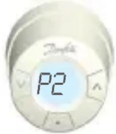
natural_image
Illustration of a mechanical valve with green directional arrows indicating movement (no text or symbols)natural_image
Diagram of a battery cell with internal components and red arrows indicating flow direction (no text or symbols)natural_image
Close-up of a hand holding a pen, pointing at a small electronic device (no visible text or symbols)
natural_image
Mechanical component diagram showing a valve assembly with green arrows indicating direction (no text or symbols)natural_image
Diagram of a battery cell with internal components and red arrows indicating flow direction (no text or symbols)3.2 living connect® installeren
natural_image
Close-up of a hand holding a pen next to a device with a screen (no visible text or symbols)natural_image
Mechanical valve assembly diagram showing a yellow connector with green directional arrows indicating motion (no text or labels)Danfoss can accept no responsibility for possible errors in catalogues, brochures and other printed material. Danfoss reserves the right to alter its products without notice. This also applies to products already on order provided that such alterations can be made without subsequential changes being necessary in specifications already agreed. All trademarks in this material are property of the respective companies. Danfoss and the Danfoss logotype are trademarks of Danfoss A/S. All rights reserved.
013R9501, VIFNE29P


- living connect® Installation and User Guide
- Thank you for buying a Danfoss product
- System overview
- Overview of display and control buttons
- Installation - step by step
- Preparation
- Inserting the batteries
- Installation of living connect®
- Configuring Danfoss Link™ CC
- Connecting to Danfoss Link™ CC
- Technical settings
- Reinstallation mode
- Testing the connection
- Adjustments for over/undersized radiators
- Reset to factory settings
- Safety precautions
- Removing living connect®
- Disposal
- User Guide for living connect®
- UK
- Contents
- Changing the batteries
- Temperature control and adjustment
- Troubleshooting
- Inhalt
- Batterien einlegen
- living connect® installeren
Brand : DANFOSS
Model : living connect
Category : Thermostat