
Project 115 - Paint gun WAGNER - Free user manual and instructions
Find the device manual for free Project 115 WAGNER in PDF.


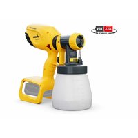
| Product Type | Electric Paint Sprayer |
| Brand | Wagner |
| Model | Project 115 |
| Dimensions (L x W x H) | 30 x 15 x 20 cm |
| Weight | 1.2 kg |
| Power Supply | 230 V ~ 50 Hz |
| Power | 500 W |
| Tank Capacity | 1 L |
| Spray Rate | 300 ml/min |
| Maximum Viscosity | 100 DIN |
| Nozzle Diameter | 1.5 mm |
| Main Functions | Paint, varnish, stain |
| Spray Pattern | Round wide (adjustable) |
| Flow Adjustment | Yes, progressive |
| Maintenance and Cleaning | Clean immediately after use with water or suitable solvent |
| Protection Rating | IP20 |
| Double Insulation | Yes |
| Spare Parts Available | Yes, via Wagner after-sales service |
| Repairability | Repairability rating: 6.5/10 (estimated) |
Frequently Asked Questions - Project 115 WAGNER
User questions about Project 115 WAGNER
0 question about this device. Answer the ones you know or ask your own.
Ask a new question about this device
Download the instructions for your Paint gun in PDF format for free! Find your manual Project 115 - WAGNER and take your electronic device back in hand. On this page are published all the documents necessary for the use of your device. Project 115 by WAGNER.
USER MANUAL Project 115 WAGNER
natural_image
Technical line drawing of a mechanical device with wheels and mounting brackets (no text or symbols)D ....2 F ....21
GB .....12 NL .....31
D GB F NL






natural_image
Technical illustration of a mechanical component with a magnified inset showing internal detail (no text or symbols)
Warnung!
Translation of the original operating instructions
Warning!
Attention: Danger of injury by injection! Airless units develop extremely high spraying pressures.


Danger

Never put your fingers, hands or any other parts of the body into the spray jet!
Never point the spray gun at yourself, other persons or animals. Never use the spray gun without safety guard.
Do not treat a spraying injury as a harmless cut. In case of injury to the skin through coating materials or solvents, consult a doctor immediately for quick and expert treatment. Inform the doctor about the coating material or solvent used.

The operating instructions state that the following points must always be observed before starting up:
- Faulty units must not be used.
- Secure WAGNER spray gun using the safety catch on the trigger.
- Ensure that the unit is properly earthed. The connection must take place through a correctly earthed two-pole and earth socket outlet.
- Check allowable operating pressure of high-pressure hose and spray gun.
- Check all connections for leaks.

The instructions regarding regular cleaning and maintenance of the unit must be strictly observed.
Before any work is done on the unit or for every break in work the following rules must be observed:
- Release the pressure from spray gun and hose.
- Secure the WAGNER spray gun using the safety catch on the trigger.
- Switch off unit.
Be safety-conscious!
General Safety Instructions
Read all the instructions. Non-observance of the instructions below can cause electric shock, fire and or serious personal injuries. The term „power tool“ used below covers both mains-operated power tools (with mains lead) and accumulator-operated power tools (without mains lead).
All local regulations in force must be observed.
Explanation of symbols used
 Danger Danger | Indicates an immediate danger. Unless avoided, death or serious injuries will result. |
 | Indicates tips for use and other particularly useful information. |
 | Wear suitable ear protection when working. |
 | Wear suitable respiratory equipment when working. |
 | Wear suitable safety gloves when working. |
1. Workplace
Keep your workplace clean and tidy. a) Untidiness and unlit working areas can lead to accidents.
Never use the tool in hazardous areas that contain b) flammable liquids, gases or dusts. Power tools generate sparks that can ignite the dust or vapors.
Keep children and other persons away when using the c) power tool. You can lose control of the tool if you are distracted.
2. Electrical Safety
The tool plug must fit into the socket. The plug may not be a) modified in any form. Do not use adaptor plugs together with protective-earthed tools. Unmodified plugs and suitable sockets reduce the risk of an electric shock.
Avoid physical contact with earthed surfaces such as pipes, b) heating elements, stoves and refrigerators. The risk through electric shock increases if your body is earthed.
Keep the equipment away from rain and moisture. c) The risk of an electric shock increases if water penetrates electrical equipment.
Do not misuse the mains lead by carrying the tool by the d) lead, hanging it from the lead or by pulling on the lead to remove the plug. Keep the lead away from heat, oil, sharp edges or moving tool parts. Damaged or twisted leads increase the risk of an electric shock.
If you work outdoors, use only extension leads that are e) approved for outdoor use. The use of an extension lead that is suitable for outdoors reduces the risk of an electric shock.
3. Safety of Persons
Be attentive. Pay attention to what you are doing and work a) sensibly with a power tool. Do not use the tool if you are tired or under the influence of drugs, alcohol or medication. Just a moment of inattentiveness while using the tool can lead to serious injuries.
b) Wear personal safety equipment and always wear safety goggles. Wearing personal protective equipment, such as dust mask, non-slip safety shoes, safety helm or ear protection, depending on the type of power tools, reduces the risk of injury.
c) Avoid accidental starting-up. Ensure that the switch is in the "OFF" position before inserting the plug into the socket. Accidents can occur if you carry the power tool while your finger is on the switch or if you connect the power tool to the power supply which it is on.
d) Remove setting tools or wrenches before switching on the power tool. A tool or wrench that is in a rotating tool part can lead to injuries.
e) Do not overestimate your abilities. Ensure that you are standing securely and have your balance at all times. This ensures that you can control the tool better in unexpected situations.
f) Wear suitable clothing. Do not wear wide clothing or jewelry. Keep your hair, clothes and gloves away from moving parts. Loose clothing, jewelry or long hair can be caught in moving parts.
g) This appliance is not intended for use by persons (including children) with reduced physical, sensory or mental capabilities, or lack of experience and knowledge, unless they have been given supervision or instruction concerning use of the appliance by a person responsible for their safety. Children should be supervised to ensure that they do not play with the appliance.
4. Careful Handling and Use of Power Tools
a) Do not overload the tool. Use the power tool designed for the work that you are doing. You work better and safer in the specified performance range if you use the suitable power tool.
b) Do not use power tools whose switch is defective. A power tool that cannot be switched on or off is dangerous and has to be repaired.
c) Remove the plug from the socket before carrying out tool settings, changing accessories or putting the tool away. This precautionary measure prevents unintentional starting of the tool.
d) Store unused power tools so that they are inaccessible to children. Do not let persons use the tool who are not familiar with it or who have not read these instructions. Power tools are dangerous when they are used by inexperienced persons.
Take proper care of your tools. Check whether the moving e) parts function trouble-free and do not jam, whether parts are broken or damaged so that the tool function is impaired. Have damaged parts repaired before using the tool. Many accidents have their origin in power tools that have been maintained badly.
Use the power tool, accessories, insert tools, etc. in f) accordance with these instructions and in a fashion specified for this special tool type. Take the working conditions and the activity to be carried out into consideration. The use of power tools for purposes other than the intended ones can lead to dangerous situations.
5. Service
Have your tool repaired only by qualified specialist a) personnel and only with original spare parts. This ensures that the tool safety is maintained.
If the supply cord is damaged, it must be replaced by the b) manufacturer or it's service agent or a similarly qualified person in order to avoid a safety hazard.
For secure handling of Airless high-pressure spraying units the following safety regulations are to be observed:
● Health protection

Caution! Wear breathing equipment: Paint mist and solvent vapors are damaging to health. Always wear breathing equipment and only work in well ventilated rooms or using supplementary ventilating equipment. It is advisable to wear working clothing, safety glasses, ear protection and gloves
- Flash point

Only use coating materials with a flash point of 21 °C or above without additional heating. The flash point is the lowest temperature at which vapors develop from the coating material. These vapors are sufficient to form an inflammable mixture over the air above the coating material.
● Explosion protection

Do not use the unit in work places which are covered to the explosion protection regulations.
● Danger of explosion and fire through sources of flame during spraying work

There may be no sources of flame such as, for example, open fires, smoking of cigarettes, cigars or tobacco pipes, sparks, glowing wires, hot surfaces, etc. in the vicinity.
● Electrostatic charging (formation of sparks or flame)

Under certain circumstances, electrostatic charging can occur on the unit due to the rate of flow of the coating material when spraying. On discharging this can result in the emergence of sparks or fire. It is
therefore necessary that the unit is always earthed through the electrical installation. The connection must take place through a correctly earthed two-pole-and-earth socket outlet.
- Ventilation
Good natural or artificial ventilation must be ensured in order to avoid the risk of explosion or fire and damage to health during spray work.
- Secure device and spray gun
All hoses, fittings, and filter parts must be secured before operating spray pump. Unsecured parts can eject at great force or leak a high pressure fluid stream causing severe injury.
Always secure the spray gun when mounting or dismounting the tip and in case of interruption to work.
● Recoil of spray gun

In case of high operating pressure, pulling the trigger can effect a recoil force of up to 15 N. If you are not prepared for this, your hand can be thrust backwards or your balance lost. This can lead to injury. Continuous stress from this recoil can cause permanent damage to health.
● Max. operating pressure
Max. permissible operating pressure for spray gun, spray gun accessories and high-pressure hose may not fall short of the maximum operating pressure of 200 bar (20 MPa) stated on the unit.
● Coating substance
Caution against dangers that can arise from the sprayed substance and observe the text and information on the containers or the specifications given by the substance manufacturer. Do not spray any liquid of unknown hazard potential.
● High-pressure hose (safety note)
Electrostatic charging of spray guns and the high-pressure hose is discharged through the high-pressure hose. For this reason the electric resistance between the connections of the high-pressure hose must be equal or lower than 197 kΩ/m (60 kΩ/ft.).

For reasons of function, safety and durability, only use genuine WAGNER high-pressure hoses and spray nozzles. For overview see „Spare parts lists“.
● Connecting the device
A properly earthed socket outlet with earthing contact must be used for connection. The connection must be equipped with a residual current protective device with INF ≤ 30 mA.
- Setting up the unit
When working indoors:

Vapors containing solvents may not be allowed to build up in the area of the device. Setting up the unit on the side a way from the sprayed object. A minimum distance of 5m between the unit and spray gun is to be maintained.
When working outdoors:

Danger
Vapors containing solvents may not be allowed to blow toward the unit.
Note the direction of the wind.
Set the unit up in such a way that vapors containing solvents do not reach the unit and build up there.
A minimum distance of 5 m between the unit and spray gun is to be maintained.
● Cleaning the unit

Danger
Danger of short circuit through penetrating water! Never spray down the unit with high-pressure or high-pressure steam cleaners.
● Cleaning units with solvents

Danger
When cleaning the unit with solvents, the solvent should never be sprayed or pumped back into a container with a small opening (bunghole). An explosive gas/air mixture can be produced. The container must be earthed.
Do not clean the device or accessories with flammable solvents with a flash point below 21 °C.
● Earthing of the object
The object to be coated must be earthed.
Components and Description
The shipping carton for your painting system contains the following:
- Spray gun with two filters (M in gun and one XS-S and one M separate) • One axle, two axle plates and four screws
- Two wheel assemblies (including 2 metal covers and 2 plastic covers) • Spray tip assembly
- 7.5 m, 1/4" internal diameter pressure hose
- One inlet valve pusher tool
• An assembly aid (positioned beneath the hopper) • Instruction manual
Figure 1 - Controls and Functions
(further, detailed descriptions of the individual items can be found in the relevant section of the operating instructions)
Item Component Description
| A) | Extendable handle......The handle extends for easy transport and storage. |
| B) | Removable Hopper......The hopper can be removed for easy emptying and cleaning. It can be removed when empty or when filled with material. Do not exceed 9.5 liters. The cover of the hopper does not seal, therefore material can emerge from the upper container if too much material is put in or the hopper tips up. |
| C) | ON / OFF Switch......The ON/OFF switch turns the power to the sprayer on and off (O=OFF, I=ON). |
| D) | PRIME / SPRAY Knob......The PRIME/SPRAY knob directs fluid to the spray hose when set to SPRAY or the return tube when set to PRIME. The arrows on the PRIME/SPRAY knob shows the rotation directions for PRIME and SPRAY. The PRIME/SPRAY knob is also used to relieve pressure built up in the spray hose (see Pressure Relief Procedure). |
| E) | Project Control......Project Control functions: Prime, Clean/Roll, Spray 1 - MAX Spray. |
| F) | Return Tube......Fluid is sent back out through the return tube to the original container when PRIME/SPRAY knob is in PRIME position. |
| G) | Handle lock......The handle lock allows the extendable handle to extend or contract. |
| H) | Spray Gun......For application of the coating material and regulation of the pump capacity. |
| I) | Spray Hose......The spray hose connects the gun to the pump. |
Technical Data
| Pump type | Piston pump |
| Power source | 230-240 V~ 50 Hz |
| Power consumption | 625 W |
| Fusing | Only connect to sockets protected with an FI fuse (16 A) |
| Double insulation | |
| Max. spray pressure | 190 bar |
| Max. delivery rate 1) | 0,8 l/min |
| Sound pressure level 2) | L_WAd = (80+3) dB (A) |
| Sound pressure output 2) | L_pAd = (91+3) db (A) |
| Oscillation level 2) | a_h = 1,2 m/s^2 Uncertainty K = 1.5 m/s2 |
| Max. temperature of coating substance | 48°C |
| Max. nozzle size | L (0,017") |
Technical Data
| Hose length | 7,5 m |
| Container capacity | 9,5 l |
| Product dimensions | 38 x 38 x 65 cm |
| Weight | 12 kg |
^1) Dispersion paint with nozzle M and a pressure of 138 bar
^2) Measured in accordance with EN 1953 in an acoustic measuring room with paint sprayed at maximum pressure
Coating Materials Suitable for Use
Water-based and solvent-containing lacquers and glazes.
Paints, oils, release agents, synthetic enamels, PVC lacquers, undercoats, base coats, fillers and anti-rust paints.
Dispersion and latex paints for interior use.
Coating Materials Not Suitable for Use
Materials that contain highly abrasive components, facade paint, caustic solutions and acidic coating substances.
Materials with a flash point below 21°C.

In order to ensure compatibility of the coating substance with the materials used to manufacture the device, please contact Wagner Service in cases of doubt.
Field of application
Coating of interior walls as well as small and medium-sized objects outdoors (e.g. garden fences, garage doors, etc.). Industrial use is excluded.
Assembly
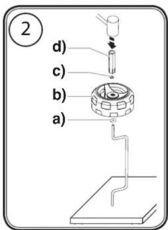
Figure 2 - Assembling the Wheels
- Slide the spacer (a), the wheel (b) and the push nut (c) over the end of the axle in the order shown. Make sure the spacer (a) is oriented so the lipped side will face toward the middle of the axle.

You will need to stand the axle vertically on a flat and stable surface to assemble the wheels.
- Lightly tap the assembly aid (d) with a mallet to secure the push nut (c) over the end of the axle. Repeat steps for other wheel.
Figure 3 - Assembling the Axle
- Slide both ends of the axle up into the slots (a) as shown. The lipped side of the spacers (b) should go inside of the axle slots.
- Make sure each axle plate is oriented and located as shown (L and R). Secure each plate with two (2) screws. Snap the wheel caps (e) over the ends of the push nuts.
Figure 4 - Assembling the Handle
-
To assemble the handle, press the button (a) as shown and slide the handle into the cart assembly.
-
Once the handle is fully inside the cart, release the button and pull the handle until it locks in up or down position.
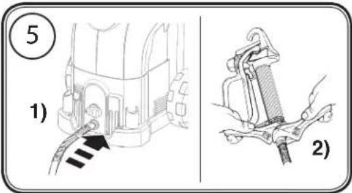
Figure 5 - Attaching the Hose

Make sure that the pump is switched off (position O) and the spray device is disconnected from the power supply.
。
- Screw the thread of the high-pressure hose onto the spray hose connection. Tighten with an adjustable wrench.
- Thread the other end of the hose to the spray gun. Grip the spray gun with an adjustable wrench on the handle, and tighten the hose nut with the other.

The spray tip should not be attached until after the sprayer and spray hose have been purged and primed.
Before You Begin
Preparation of the Coating Material
Using Project 115 interior wall paints, varnishes and glazes can be applied by spraying without diluting them, or by diluting them slightly.
Detailed information is available in the technical data sheet of the manufacturer ( Internet download).
- Stir the material up and put the required amount into the paint container.
| Thinning recommendation | |
| Sprayed material | |
| Glazes undiluted | |
| Wood preservatives containing solvents or based on water, mordants, oils, disinfection agents, plant protective agents | undiluted |
| Paints containing solvents and water-soluble paints, primers, vehicle coating paints, thick-film glazes | dilute by 5 - 10% |
| Interior wall paint (dispersions and latex paint) | dilute by 0 - 10% |
- Do a test spray (e.g. on to a piece of cardboard).

If the paint sprays evenly, as shown in fig. 14 A, all the setting must be correct.
If the paint looks stripy after spraying, as shown in fig. 14 B, gradually increase the pressure, or dilute more in 5% steps.
Figure 6 - Locking the Spray Gun

Danger
Always lock the trigger off when attaching the spray tip or when the spray gun is not in use.
- The gun is secured when the trigger lock is at a 90^ angle (perpendicular) to the trigger in either direction.
Figure 7 - Pressure Relief Procedure

Be sure to follow the Pressure Relief Procedure when shutting the unit off for any purpose. This procedure relieves the pressure from the spray hose and the gun.
-
Lock the spray gun off. Flip the ON/OFF switch to the OFF position.
-
Turn the PRIME/SPRAY knob to PRIME.

Take care not to pinch your fingers when turning the switch.
- Unlock the spray gun and trigger spray gun into the side of the material bucket. Lock the spray gun.
Figure 8 - Removing / Emptying the Hopper

Make sure your floors and furnishings are protected with drop cloths to avoid property damage.

Always place the hopper on a hard, flat, stable surface when removed.

Perform the Pressure Relief Procedure (see figure 7) and unplug the sprayer.
Danger
-
Perform Pressure Relief Procedure.
-
Pull the return tube (a) from the rear of the hopper lid.
-
Grab hopper by the side handles (b) and gently pull it out.
-
When finished emptying / cleaning, replace hopper and hopper lid.
-
Replace the return tube by inserting it through the notch in the hopper lid.

The hopper can be heavy when filled with spraying material. Make sure to lift with your legs and not your back in order to reduce the risk of injury.
Purging and Priming
Figure 9 - Priming the Sprayer

Make sure that the pump is switched off (position O) and the spray device is disconnected from the power supply.
Danger
- Pull the return tube from the hopper and hold it over a waste container.
- Turn the PRIME/SPRAY knob to PRIME. Plug in the sprayer. Press the ON/OFF switch into the ON position (I).

Any fluids remaining in the pump and the return tube will flow out of the return tube. Let the pump run until no fluid is coming from the return tube.
-
Switch the pump to OFF. Remove the return tube from the waste container and insert it into the notch in the hopper lid.
-
Remove hopper lid. Fill your hopper with the material you plan to spray. Do not exceed 2 1/2 gallons (b).
-
Switch your unit ON once more and make sure that material is flowing from the return tube. Turn pump OFF and replace the hopper lid.
Figure 10 - Releasing the Inlet Valve

If spray material does not flow from the return tube, the inlet valve may be stuck. Follow these steps.
-
Shut the unit OFF and unplug.
-
Carefully remove the hopper. Clean the connection area between the hopper and the basic unit.
- Insert the inlet pusher tool (a) into the center of the inlet valve area (b). This should release the inlet valve and allow spraying material to flow through the return tube.
- Replace hopper and return tube and resume.
Figure 11 - Priming the Spray Hose
- Unlock the spray gun and turn the PRIME/SPRAY knob to PRIME.

The spray tip should not be attached to your spray gun when purging your spray hose.
- PULL the trigger and aim the spray gun at the side wall of a waste container. If using oil-based materials, the spray gun must be grounded while purging (see warning below).

Danger
Keep hands clear from fluid stream. Ground the gun by holding it against the edge of a metal container while flushing. Failure to do so may lead to a static electric discharge which may cause a fire.
- While pulling the trigger, switch the pump ON (I), and turn the PRIME/SPRAY knob to Spray (1). Hold the trigger until all air, water, or solvent is purged from the spray hose and material is flowing freely.

Danger
If the PRIME/SPRAY knob is still on SPRAY, there will be high pressure in the hose and spray gun until the PRIME/SPRAY knob is turned to PRIME.
- Release trigger. Turn the prime/spray knob to PRIME. Turn the pump OFF (O). Trigger the gun into the waste container to be sure that no pressure is left in the hose.
Figure 12 - Attaching the Spray Tip

Danger
POSSIBLE INJECTION HAZARD. Do not spray without the tip guard in place. Never trigger the gun unless the tip is in either the spray or the unclog position. Always engage the gun trigger lock before removing, replacing or cleaning tip.
-
Lock the spray gun off.
-
Thread the tip guard onto the gun.

When attaching the tip guard to the gun, align the tip guard as shown in figure 12 (a), then tighten by hand (b).
Spraying
Figure 13 - Spraying Technique
A) The key to a good paint job is an even coating over the entire surface. Keep your arm moving at a constant speed and keep the spray gun at a constant distance from the surface. The best spraying distance is 25 to 30 cm between the spray tip and the surface.
B) Keep the spray gun at right angles to the surface. This means moving your entire arm back and forth rather than just flexing your wrist.
C) Keep the spray gun perpendicular to the surface, otherwise one end of the pattern will be thicker than the other.
D) Trigger gun after starting the stroke. Release the trigger before ending the stroke. The spray gun should be moving when the trigger is pulled and released. Overlap each stroke by about 30%. This will ensure an even coating.

When finished spraying, perform Pressure Relief Procedure.

If you expect to be away from your spray project for more than 1 hour, follow the Short Term Cleanup procedure described in the Cleanup section of this manual.
Figure 14 - Practice
- Be sure that the paint hose is free of kinks and clear of objects with sharp cutting edges.
2a. If you are spraying thicker materials, turn the PRIME/SPRAY knob to MAX SPRAY.
2b. If you are spraying thinner or lighter bodied materials, turn the PRIME/SPRAY knob to SPRAY (1).

The paint hose should stiffen as material begins to flow through it.
-
Unlock the spray gun.
-
While pointing the gun at a piece of scrap wood or cardboard, trigger the spray gun to bleed air out of the hose.
- When material reaches the spray tip, spray a test area to check the spray pattern.
- Use the lowest pressure setting necessary to get a good spray pattern (A). If the pressure is set too high, the spray pattern will be too light. If the pressure is set too low, tailing will appear or the paint will spatter out in blobs rather than in a fine spray (B).
Figure 15 - Unclogging the Spray Tip

If the spray pattern becomes distorted or stops completely while the gun is triggered, follow these steps.

Do not attempt to unclog or clean the tip with your finger. High pressure fluid can cause injection injury.
Danger
- Release the trigger and lock the gun off. Rotate the reversible tip arrow 180^ so that the point of the arrow is toward the rear of the gun (see figure 15).

Under pressure, the spray tip may be very difficult to turn. Turn the PRIME/SPRAY knob to PRIME and trigger the gun. This will relieve pressure and the tip will turn more easily.
- Turn the prime/spray knob to spray.
- Unlock the gun and squeeze the trigger, pointing the gun at a scrap piece of wood or cardboard. This allows pressure in the spray hose to blow out the obstruction. When the nozzle is clean, material will come out in a straight, high pressure stream.
- Release the trigger and lock the gun off. Reverse the tip so the arrow points forward again. Unlock the gun and resume spraying.
Cleanup

If you are using water-soluble materials, use warm suds to clean the spray device. If you are using solvent-based spray, use a suitable solvent for cleaning, with a flash point of over 21°C.

Do not use solvents for water-soluble materials, as the mixture will turn into a gel-type substance which is difficult to remove.
Figure 16 - Short Term Cleanup

Only follow these instructions when using water-soluble materials. If you are using solvent-based spray, follow the Cleanup and Long-Term Storage steps.
A) Shutdown
-
Perform the Pressure Relief Procedure (see figure 7) and unplug the sprayer.
-
Pour 1/2 cup water slowly on the top of the paint to prevent the paint from drying.
- Wrap the spray gun assembly in a damp cloth and place it in a plastic bag. Seal the bag shut. Place the sprayer in a safe place out of the sun for short-term storage.
B) Startup
- Remove the gun from the plastic bag. Stir the water into the paint.
-
Turn the PRIME/SPRAY knob to PRIME.
-
Plug sprayer in.
- Turn the switch to ON (I).
- Turn the PRIME/SPRAY knob to MAX SPRAY. Test the sprayer on a practice piece and begin spraying.
Figure 17 - Flushing the System
- Perform Pressure Relief Procedure (see figure 7).
- Empty the hopper of spraying material (see figure 8).
- While removed, rinse the hopper with the appropriate cleaning solution until clean.
- Lock the gun and remove spray tip assembly. Replace the hopper and return tube. Fill the hopper with appropriate cleaning solution.
- Place a waste container (a) next to the original material container (b). The containers should be touching. Aim the spray gun into the side of the original material container (b) and hold the trigger.
- While pulling the gun trigger, turn the pump ON (I), and turn the PRIME/ SPRAY knob to SPRAY (1) to purge material from the hose back into the original container. Keep holding trigger through next steps.
- When cleaning solution flows from the spray gun, keep holding the trigger and aim the spray gun into the side of the waste container (ground gun with a metal container if flushing with flammable solvent).
- Trigger the gun until the fluid flowing out of the gun is clear. You may need to dispose and obtain new cleaning solution.
-
Turn the PRIME/SPRAY knob to PRIME and trigger gun to relieve pressure.
-
If hopper is empty of all cleaning solution, refill with new cleaning solution.
-
Turn the PRIME/SPRAY knob to PRIME, and turn the pump ON.
-
Let the pump circulate the cleaning solution out the return tube for 2-3 minutes. Turn the pump OFF.
- Remove and thoroughly rinse the hopper once more.
- Replace the hopper for storage.
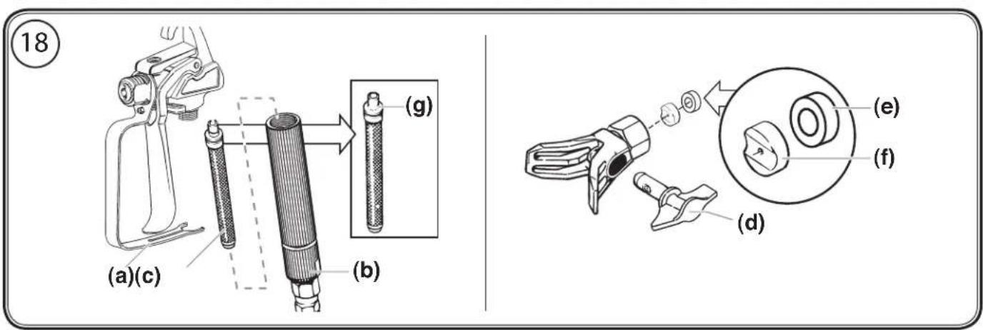
Figure 18 - Cleaning the Spray Gun
-
Perform Pressure Relief Procedure (see figure 7).
-
Make sure the pump is switched OFF (O). Make sure the PRIME/SPRAY knob is turned to PRIME. Unplug the sprayer.
-
Remove spray gun from the paint hose using adjustable wrenches.
-
Unclip the trigger guard (a) from the filter housing (b) by pulling outward from the filter housing. Unscrew the filter housing.
-
Remove the filter (c) from the spray gun housing and clean with the appropriate cleaning solution (warm suds for water-soluble materials, solvents with a flash point of over 21°C for solvent-based substances).
-
Remove spray tip (d) from spray guard assembly. Clean spray tip with a soft-bristled brush and the appropriate cleaning solution. Be sure to remove and clean the washer (e) and saddle seat (f) located in the rear of the spray tip assembly.
-
Replace the cleaned filter, tapered end first, into the gun housing. The tapered end (g) of the filter must be loaded properly into the gun. Improper assembly will result in a plugged tip or no flow from the gun.
-
Install spray tip (d), saddle seat (f) and washer (e), and replace spray guard assembly.
-
Thread the spray gun back onto the paint hose. Tighten with a wrench.
Figure 19 - Long-Term Storage
-
Perform Pressure Relief Procedure (see figure 7).
-
Remove hopper. Pour approximately two ounces of light household oil into the inlet valve (a).
-
Remove hose from spray hose port. Place a rag over the spray hose port, and turn the switch ON (I). Let the unit run for five seconds. Turn the pump OFF (O). Disconnect the spray device from the power supply.
-
Replace the hopper.
-
Wipe entire unit, hose and gun with a damp cloth to remove accumulated paint. Replace the spray hose.
-
Push handle lock to collapse the handle.
Figure 20 - Cleaning the Inlet Valve (Kit part number 0418714)

Cleaning or servicing the inlet valve may be required if the unit has priming problems. Priming problems may be prevented by properly cleaning the sprayer and following the long-term storage steps.

Perform the Pressure Relief Procedure (see figure 7) and unplug the sprayer.
-
Remove the hopper. Loosen the locknut by turning anticlockwise.
-
Remove the inlet sleeve (1) with a suitable tool (e.g. socket SW 11).
-
Inspect the threads on the inlet sleeve and the inlet sleeve O-ring (2). Remove any accumulated paint.
-
To remove the inlet valve, place the assembly aid (8) on a socket (6) with a 5/8" insert (7). Insert the inlet valve tool into the inlet valve (a). Remove the inlet valve screw connection by unscrewing anticlockwise from the housing.
-
Retrieve the inlet valve (9) and the inlet valve O-ring (10) from the inlet valve housing. Clean or replace and lubricate the O-ring with a light household oil.
-
Set the inlet valve O-ring (10) back into the housing, and set the inlet valve (9) on top of it.
-
Replace inlet fitting (8) into the housing. Tighten with the inlet valve tool (7) and ratchet (4, 5, 6).
-
Replace the seal (3). Place the inlet sleeve O-ring (2) onto the inlet valve fitting (9), and replace the inlet sleeve (1) by twisting it clockwise.
-
Replace the hopper.
Figure 21 - Cleaning the Outlet Valve
Cleaning or replacing the outlet valve may be necessary if your spray performance remains poor after having performed all the steps contained in the Troubleshooting section of this manual.

Perform the Pressure Relief Procedure (see figure 7) and unplug the sprayer.
-
Unscrew the outlet valve from the outlet valve housing using an adjustable wrench.
-
Inspect the inside of the outlet valve housing (a). Clean any accumulated paint.
-
Replace with a new outlet valve. Tighten into outlet valve housing with an adjustable wrench.
Parts Lists
Figure 22 - Spray Gun/Spray Hose
Item Part # Description Quantity
1 0418717 Gun assembly (without nozzle) .....1
2 0418705 Tip, XS ....1
2 0418707 Tip, M ....1
3 0418711 Filter, XS-S (red) 2
3 0418712 Filter, M (yellow) ....2
4 0418718 Spray hose, 7.5m, red ....1
Part # Description
| 0418705 | Spray tip, XS ......Water-soluble and solvent based enamels and paints, oils and release agents |
| 0418706 | Spray tip, S ......Synthetic resin-based paints, PVC paints |
| 0418707 | Spray tip, M ......Enamel paints, undercoats, primers, fillers, indoor latex paints and indoor emulsions |
| 0418708 | Spray tip, L ......Enamel paints, undercoats, primers, fillers, indoor latex paints and indoor emulsions, anti-corrosive paints |
0418711 Filter, XS - S (red, 2 pack)
0418712 Filter, M (yellow, 2 pack)
0418713 Filter, L - XXL+ (white, 2 pack)
0418714 Valve set (inlet and outlet valve)
All spare parts listed above are wear parts, and are not covered by warranty!
Problem
A. The sprayer does not start.
B. The sprayer starts but does not draw in paint when the PRIME/SPRAY knob is set to PRIME.
C. The sprayer draws up paint but the pressure drops when the gun is triggered.
D. The PRIME/SPRAY valve is on SPRAY and there is flow through the return tube.
E. The spray gun leaks.
F. The tip assembly leaks.
G. The spray gun will not spray.
H. The paint pattern is tailing.
Cause
| 1. | The sprayer is not plugged in. |
| 2. | The ON/OFF switch is set to OFF. |
| 3. | The sprayer shuts off while still under pressure. |
| No voltage is coming from the wall plug. | |
| The extension cord is damaged or has too low a capacity. | |
| There is a problem with the motor. |
| 1. | The unit will not prime properly or has lost prime. |
| 2. | The hopper is empty. |
| 3. | The unit is not on level ground. |
| 4. | The inlet filter is clogged. |
| 5. | The inlet or outlet valve is stuck. |
| 6. The inlet valve is worn or damaged. |
| 7. The PRIME/SPRAY valve is plugged. |
| 1. | The spray tip is worn. |
| 2. | The inlet filter is clogged. |
| 3. | The gun filter or spray tip is plugged. |
| 4. | The paint is too heavy or coarse. |
| 5. | The outlet valve assembly is worn. |
| 6. | The inlet valve assembly is damaged or worn. |
| 1. | The PRIME/SPRAY valve is dirty or worn. |
| 1. | Internal parts of the gun are worn or dirty. |
| 1. | The tip was assembled incorrectly. |
| 2. | A seal is dirty. |
| 1. | The spray tip or the gun filter is plugged. |
| 2. | The spray tip is in the reverse position. |
| 3. PRIME/SPRAY knob not set to SPRAY. |
-
The gun or the tip is plugged.
-
The tip is worn.
-
The paint is too thick.
-
Pressure loss.
Solution
| 1. | Plug the sprayer in. |
| 2. | Turn the ON/OFF switch to ON. |
| 3. | Motor will cycle ON and OFF while spraying as it needs pressure. This is normal. Resume painting. |
| 4. | Properly test the power supply voltage. |
- Replace the extension cord.
- Contact your sales point/ dealer.
- Try to prime the unit again.
- Refill the hopper.
- Relocate unit to level ground.
- Clean the inlet filter.
- Clean the inlet and outlet valves and replace any worn parts.* Inlet may be stuck from old paint. Insert inlet valve pusher tool into inlet valve.
- Replace the inlet valve.*
- Contact your sales point/ dealer.
- Replace the spray tip with a new tip.
- Clean the inlet filter.
- Clean or replace the proper filter. Always keep extra filters on hand.
- Thin or strain the paint.
- Replace the outlet valve assembly.*
- Replace the inlet valve.*
- Contact your sales point/ dealer.
- Contact your sales point/ dealer.
- Check the tip assembly and assemble properly.
- Clean the seal.
- Clean the spray tip or gun filter.
- Put the tip in the forward position.
- Turn the PRIME/SPRAY knob to SPRAY.
- Clean the gun and strain the paint.
- Replace the spray tip.
- Thin the paint.
- Refer to Causes and Solutions for problem C.
Daily Maintenance
The only daily maintenance necessary is thorough cleaning. Follow the cleaning procedures in this manual.
Extended Maintenance
Some pump parts eventually wear out from use and must be replaced. However, pump performance is the only reliable indicator of when to replace wear parts. Refer to the Troubleshooting section for more information on when to use these kits.
Figuur 3 - De as monteren
Important notes on product liability
As a result of an EC regulation being effective as from January 1, 1990, the manufacturer shall only be liable
for his product if all parts come from him or are released by him, and if the devices are properly mounted and operated.
If the user applies outside accessories and spare parts, the manufacturer's liability can fully or partially be inapplicable; in extreme cases usage of the entire device can be prohibited by the competent authorities (employer's liability insurance association and factory inspectorate division).
Only the usage of original WAGNER accessories and spare parts guarantees that all safety regulations are observed.
2 years guarantee
The guarantee runs for two years, counting from the date of sale (sales slip). It covers and is restricted to free-of-charge rectification of faults which are demonstrably attributable to the use of faulty materials in manufacture, or assembly errors; or free-of-charge replacement of the defective parts. The guarantee does not cover incorrect use or commissioning or fitting or repair work which is not stated in our operating instructions. Wearing parts are also excluded from the guarantee. The guarantee excludes commercial use. We expressly reserve the right to fulfil the guarantee. The guarantee expires if the tool is opened up by persons other than WAGNER service personnel. Transport damage, maintenance work and loss and damage due to faulty maintenance work are not covered by the guarantee. Under any guarantee claim, there must be proof of purchase of the tool through submission of the original receipt. Wherever legally possible, we exclude all liability for injury, damage or consequential loss, especially if the tool has been used for a purpose other than that stated in the operating instructions, commissioned or repaired other than in accordance with our operating instructions or if repairs are performed by someone who is unqualified. We reserve the right to perform any repairs in excess of those stated in our operating instructions. In case of guarantee or repair, please refer to your point of sale.
GB
Note on disposal:
In observance of the European Directive 2002/96/EC on waste electrical and electronic equipment and implementation in accordance with national law, this product is not to be disposed of together with household waste material but must be recycled in an environmentally friendly way!
Wagner or one of our dealers will take back your used Wagner waste electrical or electronic equipment and will dispose of it for you in an environmentally friendly way. Please ask your local Wagner service centre or dealer for details or contact us direct.
F
CE Declaration of conformity
Herewith we declare that the supplied version of
0418A - WAGNER Project 115
Complies with the following provisions applying to it:
2006/42/EG, 2004/108/EG, 2002/95/EG, 2002/96/EG
Applied harmonized standards, in particular:
EN 60335-1:2002+A11:2004+A1:2004+A12:2006+A13:2008
+A14:2010,
EN ISO 12100:2010, EN 1953:1998+A1:2009,
EN 55014-1:2006+A1:2009, EN 55014-2:1997+A1:2001+A2:2008,
EN 61000-3-2:2006+A1:2009+A2:2009, EN 61000-3-3:2008
NL
Vice President Development Manager
Product Strategy & Planning
Responsible person for documents
Responsable de la documentation

- Warnung!
- Translation of the original operating instructions
- Warning!
- Be safety-conscious!
- General Safety Instructions
- Workplace
- Electrical Safety
- Safety of Persons
- Careful Handling and Use of Power Tools
- Service
- ● Health protection
- - Flash point
- ● Explosion protection
- ● Danger of explosion and fire through sources of flame during spraying work
- ● Electrostatic charging (formation of sparks or flame)
- - Ventilation
- - Secure device and spray gun
- ● Recoil of spray gun
- ● Max. operating pressure
- ● Coating substance
- ● High-pressure hose (safety note)
- ● Connecting the device
- - Setting up the unit
- ● Cleaning the unit
- ● Cleaning units with solvents
- ● Earthing of the object
- Components and Description
- The shipping carton for your painting system contains the following:
- Coating Materials Suitable for Use
- Coating Materials Not Suitable for Use
- Field of application
- Assembly
- Figure 2 - Assembling the Wheels
- Figure 3 - Assembling the Axle
- Figure 4 - Assembling the Handle
- Figure 5 - Attaching the Hose
- 。
- Before You Begin
- Preparation of the Coating Material
- Figure 6 - Locking the Spray Gun
- Danger
- Figure 7 - Pressure Relief Procedure
- Figure 8 - Removing / Emptying the Hopper
- Purging and Priming
- Spraying
- Figure 14 - Practice
- The paint hose should stiffen as material begins to flow through it.
- Figure 15 - Unclogging the Spray Tip
- If the spray pattern becomes distorted or stops completely while the gun is triggered, follow these steps.
- Do not attempt to unclog or clean the tip with your finger. High pressure fluid can cause injection injury.
- Under pressure, the spray tip may be very difficult to turn. Turn the PRIME/SPRAY knob to PRIME and trigger the gun. This will relieve pressure and the tip will turn more easily.
- Cleanup
- If you are using water-soluble materials, use warm suds to clean the spray device. If you are using solvent-based spray, use a suitable solvent for cleaning, with a flash point of over 21°C.
- Do not use solvents for water-soluble materials, as the mixture will turn into a gel-type substance which is difficult to remove.
- Figure 16 - Short Term Cleanup
- Only follow these instructions when using water-soluble materials. If you are using solvent-based spray, follow the Cleanup and Long-Term Storage steps.
- A) Shutdown
- B) Startup
- Figure 17 - Flushing the System
- Figure 18 - Cleaning the Spray Gun
- Figure 19 - Long-Term Storage
- Figure 21 - Cleaning the Outlet Valve
- Parts Lists
- Daily Maintenance
- Extended Maintenance
- Figuur 3 - De as monteren
- Important notes on product liability
- years guarantee
- GB
- Note on disposal:
- F
- CE Declaration of conformity
Brand : WAGNER
Model : Project 115
Category : Paint gun