
AGM1041 - Grinder Ferm - Free user manual and instructions
Find the device manual for free AGM1041 Ferm in PDF.


| Product Type | Electric Garden Shredder |
| Brand | Ferm |
| Model | AGM1041 |
| Power Supply | 220-240 V ~ 50 Hz |
| Motor Power | 2400 W |
| Cutting Type | Hardened Steel Blade System |
| Max Branch Diameter | 40 mm |
| Collection Bag Capacity | 50 L |
| Dimensions (L × W × H) | 60 × 40 × 80 cm |
| Weight | 15 kg |
| Noise Level | 95 dB(A) |
| Safety | Safety switch, overload protection, pusher included |
| Maintenance | Regular blade cleaning, lubrication, emptying the bag |
| Spare Parts | Replacement blades, bolts, collection bag |
| Repairability | Repairability index: 7.5/10 (according to French decree) |
| Warranty | 2 years |
Frequently Asked Questions - AGM1041 Ferm
User questions about AGM1041 Ferm
0 question about this device. Answer the ones you know or ask your own.
Ask a new question about this device
Download the instructions for your Grinder in PDF format for free! Find your manual AGM1041 - Ferm and take your electronic device back in hand. On this page are published all the documents necessary for the use of your device. AGM1041 by Ferm.
USER MANUAL AGM1041 Ferm
natural_image
Fermis graser with blue handle and orange grip, displayed on textured surface (no visible text or symbols)EN Original instructions 04
DE Übersetzung der Originalbetriebsanleitung 10
NL Vertaling van de oorspronkelijke gebruiksaanwijzing 18
FR Traduction de la notice originale 25
ES Traducción del manual original 32
PT Tradução do manual original 39
IT Traduzione delle istruzioni originali 46
SV Översättning av bruksanvisning i original 53
FI Alkuperäisten ohjeiden käännös 60
NO Oversatt fra orginal veiledning 66
DA Oversættelse af den originale brugsanvisning 73
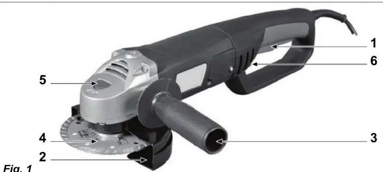
Fig. 1

Fig. 2
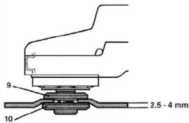
Fig. 3

Fig. 4
Fig. 5

Fig. 6
natural_image
Diagram of a mechanical component with motion arrows indicating rotational motion (no text or symbols)ANGLE GRINDER
Thank you for buying this Ferm product.
By doing so you now have an excellent product, delivered by one of Europe's leading suppliers. All products delivered to you by Ferm are manufactured according to the highest standards of performance and safety. As part of our philosophy we also provide an excellent customer service, backed by our comprehensive Warranty. We hope you will enjoy using this product for many years to come.
The numbers in the following text refer to the drawing on page 2-3

For your own safety and that of others, we recommend that you read this instruction manual carefully before using this machine. Keep this instruction manual and the documentation provided with the machine for future reference.
Introduction
This machine is developed for grinding and roughing of metal and stone. With help of the correct accessories the machine can also be used for brushing and sanding.
Contents
- Machine data
- Safety instructions
- Assembly
- Use
- Service & maintenance
1. MACHINE DATA
Contents of packing
1 Angle grinder
1 Side handle
1 Spanner
1 Set carbon brushes
1 Instruction manual
1 Safety instructions
1 Warranty card
Check the machine, loose parts and accessories for transport damage.
Technical specification
| Voltage 230 V | |
| Frequency 50 Hz | |
| Power input 1050 W | |
| No-load speed 11000/min | |
| Disc diameter 125 mm | |
| Spindle dimension M14 | |
| Weight 2.45 kg | |
| Lpa (sound pressure) 90 dB(A) K=3dB | |
| Lwa (sound power) | 101 dB(A) K=3dB |
| Vibration value | 2,989+1.5 m/s ^2 |
Vibration level
The vibration emission level stated in this instruction manual has been measured in accordance with a standardised test given in EN 60745; it may be used to compare one tool with another and as a preliminary assessment of exposure to vibration when using the tool for the applications mentioned
- using the tool for different applications, or with different or poorly maintained accessories, may significantly increase the exposure level
- the times when the tool is switched off or when it is running but not actually doing the job, may significantly reduce the exposure level
Protect yourself against the effects of vibration by maintaining the tool and its accessories, keeping your hands warm, and organizing your work patterns
Features
Fig. 1
- On/off switch
- Guard
- Side handle
- Grinding disc
- Spindle lock
- Switch lock
2. SAFETY INSTRUCTIONS
Explanation of the symbols

Denotes risk of personal injury, loss of life or damage to the tool in case of non-observance of the instructions in this manual.

Indicates electrical shock hazard.

Use spindle lock only in stand still mode.

Risk of fire.

Keep bystanders away.

Wear ear and eye protection.

Wear protective gloves.
Safety Warnings Common for Grinding or Abrasive Cutting-Off Operations:
a) This power tool is intended to function as a grinder or cut-off tool. Read all safety warnings, instructions, illustrations and specifications provided with this power tool. Failure to follow all instructions listed below may result in electric shock, fire and/or serious injury.
b) Operations such as sanding, wire brushing or polishing are not recommended to be performed with this power tool. Operations for which the power tool was not designed may create a hazard and cause personal injury.
c) Do not use accessories which are not specifically designed and recommended by the tool manufacturer. Just because the accessory can be attached to your power tool, it does not assure safe operation.
d) The rated speed of the accessory must be at least equal to the maximum speed marked on the power tool. Accessories running faster than their rated speed can break and fly apart.
e) The outside diameter and the thickness of your accessory must be within the capacity rating of your power tool. Incorrectly sized accessories cannot be adequately guarded or controlled.
f) The arbour size of wheels, flanges, backing pads or any other accessory must properly fit the spindle of the power tool. Accessories with arbour holes that do not match the mounting hardware of the power tool will run out of
balance, vibrate excessively and may cause loss of control.
g) Do not use a damaged accessory. Before each use inspect the accessory such as abrasive wheels for chips and cracks, backing pad for cracks, tear or excess wear, wire brush for loose or cracked wires. If power tool or accessory is dropped, inspect for damage or install an undamaged accessory. After inspecting and installing an accessory, position yourself and bystanders away from the plane of the rotating accessory and run the power tool at maximum no-load speed for one minute.
Damaged accessories will normally break apart during this test time.
h) Wear personal protective equipment. Depending on application, use face shield, safety goggles or safety glasses. As appropriate, wear dust mask, hearing protectors, gloves and workshop apron capable of stopping small abrasive or workpiece fragments. The eye protection must be capable of stopping flying debris generated by various operations. The dust mask or respirator must be capable of filtrating particles generated by your operation. Prolonged exposure to high intensity noise may cause hearing loss.
i) Keep bystanders a safe distance away from work area. Anyone entering the work area must wear personal protective equipment. Fragments of workpiece or of a broken accessory may fly away and cause injury beyond immediate area of operation.
j) Hold power tool by insulated gripping surfaces only, when performing an operation where the cutting accessory may contact hidden wiring or its own cord. Cutting accessory contacting a "live" wire may make exposed metal parts of the power tool "live" and shock the operator.
k) Position the cord clear of the spinning accessory. If you lose control, the cord may be cut or snagged and your hand or arm may be pulled into the spinning accessory.
I) Never lay the power tool down until the accessory has come to a complete stop. The spinning accessory may grab the surface and pull the power tool out of your control.
m) Do not run the power tool while carrying it at your side. Accidental contact with the spinning accessory could snag your clothing, pulling the accessory into your body.
n) Regularly clean the power tool's air vents.
The motor's fan will draw the dust inside the housing and excessive accumulation of powdered metal may cause electrical hazards.
o) Do not operate the power tool near flammable materials. Sparks could ignite these materials.
p) Do not use accessories that require liquid coolants. Using water or other liquid coolants may result in electrocution or shock.
Kickback and Related Warnings
Kickback is a sudden reaction to a pinched or snagged rotating wheel, backing pad, brush or any other accessory. Pinching or snagging causes rapid stalling of the rotating accessory which in turn causes the uncontrolled power tool to be forced in the direction opposite of the accessory's rotation at the point of the binding.
For example, if an abrasive wheel is snagged or pinched by the workpiece, the edge of the wheel that is entering into the pinch point can dig into the surface of the material causing the wheel to climb out or kick out. The wheel may either jump toward or away from the operator, depending on direction of the wheel's movement at the point of pinching. Abrasive wheels may also break under these conditions.
Kickback is the result of power tool misuse and/or incorrect operating procedures or conditions and can be avoided by taking proper precautions as given below.
a) Maintain a firm grip on the power tool and position your body and arm to allow you to resist kickback forces. Always use auxiliary handle, if provided, for maximum control over kickback or torque reaction during start-up. The operator can control torque reactions or kickback forces, if proper precautions are taken.
b) Never place your hand near the rotating accessory. Accessory may kickback over your hand.
c) Do not position your body in the area where power tool will move if kickback occurs. Kickback will propel the tool in direction opposite to the wheel's movement at the point of snagging.
d) Use special care when working corners, sharp edges etc. Avoid bouncing and snagging the accessory. Corners, sharp edges or bouncing have a tendency to snag the rotating accessory and cause loss of control or kickback.
e) Do not attach a saw chain woodcarving blade or toothed saw blade. Such blades create frequent kickback and loss of control.
Safety Warnings Specific for Grinding and Abrasive Cutting-Off Operations:
a) Use only wheel types that are recommended for your power tool and the specific guard designed for the selected wheel. Wheels for which the power tool was not designed cannot be adequately guarded and are unsafe.
b) The guard must be securely attached to the power tool and positioned for maximum safety, so the least amount of wheel is exposed towards the operator. The guard helps to protect operator from broken wheel fragments and accidental contact with wheel.
c) Wheels must be used only for recommended applications. For example: do not grind with the side of cut-off wheel. Abrasive cut-off wheels are intended for peripheral grinding, side forces applied to these wheels may cause them to shatter.
d) Always use undamaged wheel flanges that are of correct size and shape for your selected wheel. Proper wheel flanges support the wheel thus reducing the possibility of wheel breakage. Flanges for cut-off wheels may be different from grinding wheel flanges.
e) Do not use worn down wheels from larger power tools. Wheel intended for larger power tool is not suitable for the higher speed of a smaller tool and may burst.
Additional Safety Warnings Specific for Abrasive Cutting-Off Operations:
a) Do not “jam” the cut-off wheel or apply excessive pressure. Do not attempt to make an excessive depth of cut. Overstressing the wheel increases the loading and susceptibility to twisting or binding of the wheel in the cut and the possibility of kickback or wheel breakage.
b) Do not position your body in line with and behind the rotating wheel. When the wheel, at the point of operation, is moving away from your body, the possible kickback may propel the spinning wheel and the power tool directly at you.
c) When wheel is binding or when interrupting a cut for any reason, switch off the power tool and hold the power tool motionless until the wheel comes to a complete stop. Never attempt to remove the cut-off wheel from the
cut while the wheel is in motion otherwise kickback may occur. Investigate and take corrective action to eliminate the cause of wheel binding.
d) Do not restart the cutting operation in the workpiece. Let the wheel reach full speed and carefully reenter the cut. The wheel may bind, walk up or kickback if the power tool is restarted in the workpiece.
e) Support panels or any oversized workpiece to minimize the risk of wheel pinching and kickback. Large workpieces tend to sag under their own weight. Supports must be placed under the workpiece near the line of cut and near the edge of the workpiece on both sides of the wheel.
f) Use extra caution when making a "pocket cut" into existing walls or other blind areas. The protruding wheel may cut gas or water pipes, electrical wiring or objects that can cause kickback.
Special safety instructions
- Check that the maximum speed indicated on the grinding disc corresponds to the maximum speed of the machine.
The speed of the machine must not exceed the value on the grinding disc. - Make sure that the dimensions of the grinding disc correspond to the specifications of the machine.
- Make sure that the grinding disc has been mounted and fastened properly. Do not use reducing rings or adapters to make the grinding disc fit properly.
- Treat and store grinding discs in conformance with the supplier's instructions.
- Do not use the machine for grinding workpieces with a maximum thickness exceeding the maximum grinding depth of the grinding disc.
• Do not use grinding discs for deburring. - When grinding discs have to be mounted on the thread of the spindle, make sure that the spindle has sufficient thread. Make sure that the spindle is sufficiently protected and does not touch the grinding surface.
- Before use, inspect the grinding disc for any damage. Do not use grinding discs which are cracked, ripped or otherwise damaged.
- Before use, let the machine run idle for 30 seconds. Immediately switch off the machine in case of abnormal vibrations or occurrence of another defect. Carefully inspect the machine and grinding disc before switching
the machine on again.
• Make sure that sparks do not put people into danger or that they contact highly flammable substances.
- Make sure that the workpiece is sufficiently supported or clamped. Keep your hands away from the surface to be cut.
- Always wear safety goggles and hearing protection. If desired or required also use another kind of protection like for example an apron or helmet.
- Ensure that mounted wheels and points are fitted in accordance with the manufacturer's instructions.
- Ensure that blotters are used when they are provided with the bonded abrasive product and when they are required.
- If a guard is supplied with the tool never use the tool without such a guard.
- For tools intended to be fitted with threaded hole wheel, ensure that the thread in the wheel is long enough to accept the spindle length.
- Ensure that ventilation openings are kept clear when working in dusty conditions. If it should become nessesary to clear dust, first disconnect the tool from the mains supply (use non metallic objects) and avoid damaging internal parts.
- Though poor conditions of the electrical mains, shortly voltage drops can appear when starting the equipment. This can influence other equipment (eq. blinking of a lamp). If the mains-impedance Zmax <0.348 Ohm, such disturbances are not expected. (In case of need, you may contact your local supply authority for further information.
Immediately switch off the machine when:
- Excessive sparking of the carbon brushes and verticiliosis in the collector.
- Interruption of the mains plug, mains lead or mains lead damage.
- Defect switch
• Smoke or stench of scorched isolation
Electrical safety
When using electric machines always observe the safety regulations applicable in your country to reduce the risk of fire, electric shock and personal injury. Read the following safety instructions and also the enclosed safety instructions.

Always check that the power supply corresponds to the voltage on the rating plate.

Class II machine – Double insulation – You don't need any earthed plug.
Replacing cables or plugs
Immediately throw away old cables or plugs when they have been replaced by new ones. It is dangerous to insert the plug of a loose cable in the wall outlet.
Using extension cables
Only use an approved extension cable suitable for the power input of the machine. The minimum conductor size is 1,5 mm ^2 . When using a cable reel always unwind the reel completely.
3. ASSEMBLY

Prior to mounting an accessory always unplug the tool.
Assembling the hand grip
Fig. 1
The hand grip is suitable for either left or right-handed use.
- Turn the hand grip (3) to the notch on the right side of the machine for left-handed use.
- Turn the hand grip (3) to the notch on the left side of the machine for right-handed use.
- Turn the hand grip to the notch on the top of the machine to use it vertically.
Mounting a grinding disc
Fig. 2
Use grinding discs of the correct dimension. Use fibre reinforced grinding discs only.
The grinding disc must not touch the edge of the guard.
- Press the spindle lock (6) and turn the spindle (9) until it engages in the lock. Keep the spindle lock pressed during this procedure.
- Remove the flange nut (12) from the spindle using the spanner (11).
• Position the grinding disc (7) on the flange (5). - Place the flange nut on the spindle an tighten it using the spanner.
- Release the spindle lock and check that the spindle is unlocked by rotating it.
Mounting grinding discs and roughing discs
Fig. 3 and 4 show how to mount the flange (10) when using thick (4 - 8 mm) and thin (2,5 - 4 mm) discs.
The following grinding discs can be used with this grinder.
- For deburring: grooved, fibreglass reinforced type 27. Dimensions ∅ 125x6.0x22.2 mm.
- For slitting/ cutting: grooved, fibreglass reinforced, type 41 and type 42. Dimensions ∅ 125x3.0x22.2 mm.

If you use normal grinding discs they should always be fibreglass reinforced.
4. USE

Always follow the safety instructions and keep to the applicable regulations.
Hold the machine away from the workpiece when turning it on and off because the grinding disc could damage the workpiece.
- Clamp the workpiece firmly or use another method to ensure that it cannot move while working.
- Check the discs regularly. Worn grinding discs have a negative effect on the machine's efficiency. Change to a new grinding disc in good time.
• Always first turn the machine off after use before removing the plug from the socket.
Deburring
Fig. 5
An angle of inclination of 30^ to 40^ will give the best results when deburring. Move the machine back and forth using light pressure. This will prevent the workpiece from discolouring or becoming too hot and will avoid making groves.

Never use abrasive cutting discs for deburring work!
Cutting
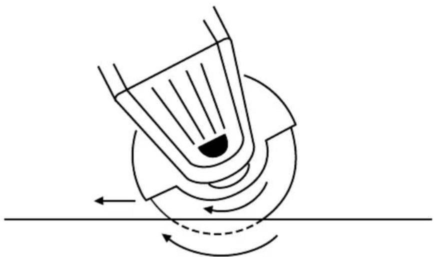
Fig. 6
Maintain firm contact with the workpiece to prevent vibration and do not tilt or apply pressure and when cutting. Use moderate pressure when working, appropriate to the material that is being worked on. Do not slow down grinding discs by applying sideways counter pressure. The direction in which you want to cut is important. The machine must always work against the direction of the cut; so never move the machine in the other direction! There is the risk that the machine will catch in the cut causing kickback and that you will lose control.
The ON/OFF/ switch
Fig. 1
Switch ON
Use one finger to push the lock button forward and then press the switch.
Switch OFF
Release the switch.

The grinder will continue to run after it is turned off.
Only lay the machine down once the motor has completely stopped turning. Do not put the machine on a dusty surface. Dust particles can penetrate the machine.

Never use the spindle key to stop the motor turning.

Never use the machine to grind magnesium workpieces.
5. SERVICE & MAINTENANCE

Make sure that the machine is not live when carrying out maintenance work on the motor.
This machine has been designed to operate over a long period of time with a minimum of maintenance. Continuous satisfactory operation depends upon proper machine care and regular cleaning.
Cleaning
Keep the ventilation slots of the machine clean to prevent overheating of the engine.
Regularly clean the machine housing with a soft cloth, preferably after each use. Keep the ventilation slots free from dust and dirt. If the dirt does not come off use a soft cloth moistened with soapy water. Never use solvents such as petrol, alcohol, ammonia water, etc. These solvents may damage the plastic parts.
Lubrication
The machine requires no additional lubrication.
Trouble shooting
Below we have listed a few probable causes and solutions to which you can refer if your circular saw does not function properly.
1. Machine fails to operate.
• Power turned off.
• (Extension) cable damaged.
2. The elektromotor hardly reaches maximum speed.
- The extension cable is too thin and/or too long.
• The mains voltage is lower than 230 V.
3. Machine overheats.
• Air vents are blocked. Clean them with a dry cloth.
- The machine has been overloaded. Use the machine for the purpose it is made for.
4. Excessive sparking or elektromotor runs irregular.
- There's dirt inside the motor or the carbon brushes are worn.
- Replace the carbon brushes or bring the machine to a specialized repair centre.
Faults
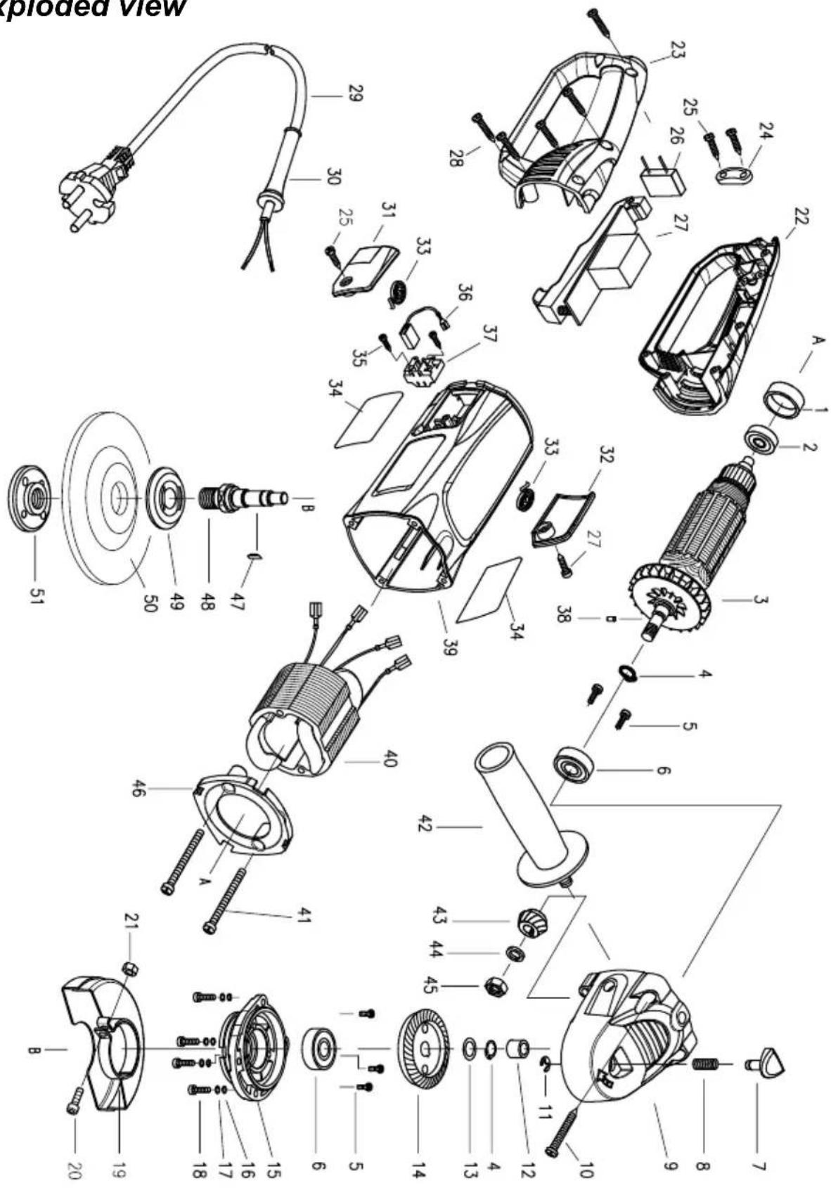
Should a fault occur, e.g. after wear of a part, please contact the service address on the warranty card. Separately you will find an exploded view showing the parts that can be ordered.
Environment
To prevent damage during transport, the appliance is delivered in a solid packaging which consists largely of reusable material. Therefore please make use of options for recycling the packaging.

Damaged and/or disposed of electrical or electronic devices must be dropped off at recycling stations intended for that purpose.
Warranty
For the conditions of warranty, please refer to the separately provided warranty card.
The product and the user manual are subject to change. Specifications can be changed without further notice.
WINKELSCHLEIFER
3. La machine surchauffe.
O interruptor ON/OFF
Fig. 1
Interruptor On (Ligado)
5. SERVICE OG VEDLIKEHOLD

DECLARATION OF CONFORMITY
(GB) We declare under our sole responsibility that this product is in conformity and accordance with the following standards and regulations:
(DE) Der Hersteller erklärt eigenverantwortlich, dass dieses Produkt den folgenden Standards und Vorschriften entspricht:
(NL) Wij verklaren onder onze volledige verantwoordelijkheid dat dit product voldoet aan, en in overeenstem ming is met, de volgende standaarden en reguleringen:
(FR) Nous déclarons sous notre seule responsabilité que ce produit est conforme aux standards et directives suivants:
(ES) Declaramos bajo nuestra exclusiva responsabilidad que este producto cumple con las siguientes normas y estándares de funcionamiento:
(PT) Declaramos por nossa total responsabilida-de que este produto está em conformidade e cumpre as normas e regulamentações que se seguem:
(IT) Dichiariamo, sotto la nostra responsabilità, che questo prodotto è conforme alle normative e ai regolamenti seguenti:
(SV) Vi garanterar på eget ansvar att denna produkt uppfyller och följer följande standarder och bestämmelser:
(FI) Vakuutamme yksinomaan omalla vastuullamme, että tämä tuote täyttää seuraavat standardit ja säädökset:
(NO) Vi erklærer under vårt eget ansvar at dette produktet er i samsvar med følgende standarder og regler:
(DA) Vi erklærer under eget ansvar, at dette produkt er i overensstemmelse med følgende standarder og bestemmelser:
(HU) Felelősségünk teljes tudatában kijelentjük, hogy ez a termék teljes mértékben megfelel az alábbi szabványoknak és előírásoknak:
(CS) Na naši vlastní zodpovědnost prohlašujeme, že je tento výrobek v souladu s následujícími standardy a normami:
(SK) Vyhlasujeme na našu výhradnú zodpovednosť, že tento výrobok je v zhode a súlade s nasledujúcimi normami a predpismi:
(SL) S polno odgovornostjo izjavljamo, da je ta izdelek v skladu in da odgovarja naslednjim standardom terpredpisom:
(PL) Deklarujemy na własną odpowiedzialność, że ten produkt spełnia wymogi zawarte w następujących normach i przepisach:
(LT) Prisiimdami visą atsakomybę deklaruojame, kad śis gaminys atitinka žemiau paminėtus standartus arba nuostatus:
(LV) Apgalvojam ar visu atbildību, ka šis produkts ir saskaņā un atbilst sekojošiem standartiem un nolikumiem:
(ET) Deklareerime meie ainuvastutusel, et see toode on vastavuses ja kooskõlas järgmiste standardite ja määrustega:
(RO) Declarăm prin aceasta cu răspunderea deplină că produsul acesta este în conformitate cu următoarele standarde sau directive:
(HR) Izjavljujemo pod vlastitom odgovornoL,šu da je strojem ukladan sa slijedešim standardima ili standardiziranim dokumentima i u skladu sa odredbama:
(SR) Pod punom odgovornošću izjavljujemo da je usaglašen sa sledećim standardima ili normama:
(RU) Под свою ответственность заявляем, что данное изделие соответствует следующим стандартам и нормам:
(UK) На свою власну відповідальність заявляємо, що дане обладнання відповідає наступним стандартам і нормативам:
(EL) Δηλώνουμε υπεύθυνα ότι προϊόν αυτό συμφωνεί και τηρεί τους παρακάτω κανονισμο ύς και πρότυπα:
(BG) Ние заявяваме, по своя собствена отговорност, че този продукт отговаря на следните стандарти и директиви
EN 55014-1, EN 55014-2, EN 60745-1, EN 60745-2-6, EN 61000-3-2, EN 61000-3-3
2006/42/EC, 2006/95/EC, 2004/108/EC, 2002/96/EC, 2006/95/EC
Zwolle, 01-10-2011
I. Mönnink
CEO Ferm BV
It is our policy to continuously improve our products and we therefore reserve the right to change the product specification without prior notice.
Ferm BV • Lingenstraat 6 • 8028 PM • Zwolle The Netherlands
Spare parts list
| Position Description No. | ||
| 2 Bearing 800607 | ||
| 3 Rotor 300708 | ||
| 6 Bearing 806000 | ||
| 14 Gear 300709 | ||
| 19 till 21 Guard complete 300775 | ||
| 27 Switch 300711 | ||
| 33 Carbon brush spring 300712 | ||
| 36 Carbon brush set 300713 | ||
| 37 Carbon brush holder 300714 | ||
| 40 Stator 300715 | ||
| 42 Auxiliary handle 300716 | ||
| 43 Pinion gear | 300717 | |
| 47 + 48 Spindle | 300718 | |
| 49 + 51 Flange set | 300719 | |
Exploded view


- ANGLE GRINDER
- Thank you for buying this Ferm product.
- The numbers in the following text refer to the drawing on page 2-3
- Introduction
- Contents
- MACHINE DATA
- Contents of packing
- Technical specification
- Vibration level
- Features
- Fig. 1
- SAFETY INSTRUCTIONS
- Explanation of the symbols
- Safety Warnings Common for Grinding or Abrasive Cutting-Off Operations:
- Kickback and Related Warnings
- Safety Warnings Specific for Grinding and Abrasive Cutting-Off Operations:
- Additional Safety Warnings Specific for Abrasive Cutting-Off Operations:
- Special safety instructions
- Electrical safety
- Replacing cables or plugs
- Using extension cables
- ASSEMBLY
- Assembling the hand grip
- Mounting a grinding disc
- Fig. 2
- Mounting grinding discs and roughing discs
- USE
- Deburring
- Fig. 5
- Cutting
- Fig. 6
- The ON/OFF/ switch
- Switch ON
- Switch OFF
- SERVICE & MAINTENANCE
- Cleaning
- Lubrication
- Trouble shooting
- Machine fails to operate.
- The elektromotor hardly reaches maximum speed.
- Machine overheats.
- Excessive sparking or elektromotor runs irregular.
- Faults
- Environment
- Warranty
- WINKELSCHLEIFER
- La machine surchauffe.
- O interruptor ON/OFF
- Interruptor On (Ligado)
- SERVICE OG VEDLIKEHOLD
- DECLARATION OF CONFORMITY
Brand : Ferm
Model : AGM1041
Category : Grinder