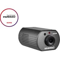
VC-A50SB - Security Camera Lumens - Free user manual and instructions
Find the device manual for free VC-A50SB Lumens in PDF.


| Product Type | Security Camera |
| Model | VC-A50SB |
| Brand | Lumens |
| Dimensions (H x W x D) | 120 mm x 80 mm x 80 mm |
| Weight | 500 g |
| Power Supply | PoE (802.3af) or DC 12V |
| Power Consumption | 8W max |
| Image Sensor | 1/2.8" Progressive CMOS |
| Resolution | 1920 x 1080 (Full HD) |
| Frame Rate | 30 fps |
| Lens | 2.8 mm fixed, F1.8 |
| Field of View | Horizontal: 100°, Vertical: 55° |
| Night Vision | IR LEDs, up to 20 m range |
| Compression | H.265 / H.264 |
| Audio | Built-in microphone, 1-way audio |
| Storage | microSD slot (up to 128 GB), NVR compatible |
| Connectivity | Ethernet 10/100 Mbps, Wi-Fi (optional) |
| Mounting | Ceiling or wall mount (bracket included) |
| Weather Rating | IP66 (outdoor) |
| Operating Temperature | -10°C to 50°C |
| Maintenance | Clean lens with a soft, dry cloth. Do not use harsh chemicals. |
| Safety | Use only the supplied power adapter. Do not expose to extreme temperatures. |
| Compliance | CE, FCC, RoHS |
Frequently Asked Questions - VC-A50SB Lumens
User questions about VC-A50SB Lumens
0 question about this device. Answer the ones you know or ask your own.
Ask a new question about this device
Download the instructions for your Security Camera in PDF format for free! Find your manual VC-A50SB - Lumens and take your electronic device back in hand. On this page are published all the documents necessary for the use of your device. VC-A50SB by Lumens.
USER MANUAL VC-A50SB Lumens
Installation Guide - English

[Important]
To download the latest version of Quick Start Guide, multilingual user manual, software, or driver, etc., please visit Lumens
http://www.MyLumens.com
Table of Contents
Copyright Information......3
Chapter 1 Safety Instructions ....4
Precautions 5
FCC Warning....5
EN55022 (CE Radiation) Warning 5
KCC Warning 6
Chapter 2 Package Contents....7
Chapter 3 Product Overview ...... 8
3.1 Overview....8
3.2 Description of LED indicator....8
Chapter 4 Instruction for Installation ...... 9
4.1 Preparation before installation....9
4.2 Instruction for installation....9
4.3 Connecting the device....19
Chapter 5 Remote Control and Setting Menu....22
5.1 Functions of remote control....22
5.2 Setting Menu 23
Chapter 6 Descriptions of Major Functions....31
6.1 I would like to switch to VC-A50S....31
6.2 I would like to save the current lens position data....31
6.3 I would like to clear the saved position data.... 31
6.4 I would like to turn on the back light compensation function...... 31
6.5 I would like to adjust the shooting angle of the lens....31
6.6 I would like to zoom in/out images 32
6.7 I would like to adjust the focal length 32
6.8 I would like to adjust the AF speed....32
6.9 I would like to set the image mode....33
6.10 I would like to freeze images....33
6.11 I would like to rotate the image....33
6.12 I would like to change the camera direction 34
6.13 I would like to display the current status .... 34
Chapter 7 DIP Switch Setting....35
7.1 DIP SWITCH 35
7.2 RS-422 Connection 37
Chapter 8 Troubleshooting....39
Copyrights © Lumens Digital Optics Inc. All rights reserved.
Lumens is a trademark that is currently being registered by Lumens Digital Optics Inc.
Copying, reproducing or transmitting this file is not allowed if a license is not provided by Lumens Digital Optics Inc. unless copying this file is for the purpose of backup after purchasing this product.
In order to keep improving the product, Lumens Digital Optics Inc. hereby reserves the right to make changes to product specifications without prior notice. The information in this file is subject to change without prior notice.
To fully explain or describe how this product should be used, this manual may refer to names of other products or companies without any intention of infringement.
Disclaimer of warranties: Lumens Digital Optics Inc. is neither responsible for any possible technological, editorial errors or omissions, nor responsible for any incidental or related damages arising from providing this file, using, or operating this product.
Always follow these safety instructions when setting up and using the HD Camera:
- Use attachments only as recommended.
- Use the type of power source indicated on the HD Camera. If you are not sure of the type of power available, consult your distributor or local electricity company for advice.
- Always take the following precautions when handling the plug. Failure to do so may result in sparks or fire:
■ Ensure the plug is free of dust before inserting it into a socket.
■ Ensure that the plug is inserted into the socket securely.
- Do not overload wall sockets, extension cords or multi-way plug boards as this may cause fire or electric shock.
- Do not place the HD Camera where the cord can be stepped on as this may result in fraying or damage to the lead or the plug.
- Do not block the slots and openings in the case of HD Camera. They provide ventilation and prevent the HD Camera from overheating. Do not place the HD Camera on the soft surface of sofas, carpets or others.
- Never push objects of any kind through cabinet slots. Never allow liquid of any kind to spill into the HD Camera.
- Except as specifically instructed in this User Manual, do not attempt to operate this product by yourself. Opening or removing covers may expose you to dangerous voltages and other hazards. Refer all servicing to licensed service personnel.
- Unplug the HD Camera during thunderstorms or if it is not going to be used for an extended period. Do not place the HD Camera or remote control on top of vibrating equipment or heated objects such as a car, etc.
- Unplug the HD Camera from the wall outlet and refer servicing to licensed service personnel when the following situations happen:
■ If the power cord or plug becomes damaged or frayed.
■ If the camera is wet with liquid, rain or water.
■ Precautions
Warning: To reduce the risk of fire or electric shock, do not expose this appliance to rain or moisture.
If HD Camera will not be used for an extended time, unplug it from the power socket.
 | NoteRisk of Electric ShockPlease do not open it by yourself |  | ||
| Caution: To reduce the risk of electric shock, do not remove cover (or back). No user-serviceable parts inside. Refer servicing to licensed service personnel. | ||||
 | This symbol indicates that this equipment may contain dangerous voltage which could cause electric shock. |  | This symbol indicates that there are important operating and maintenance instructions in this User Manual with this unit. | |
■ FCC Warning
This HD Camera has been tested and found to comply with the limits for a Class A digital device, pursuant to Article 15-J of FCC Rules. These limits are designed to provide reasonable protection against harmful interference in a commercial installation.
This digital apparatus does not exceed the Class A limits for radio noise emissions from digital apparatus as set out in the interference-causing equipment standard entitled "Digital Apparatus," ICES-003 of Industry Canada.
This product is intended for use in a commercial, industrial, or educational environment. It is not intended for residential use.
This is a Class A product. In a residential environment it may cause radio interference, in which case the user may be required to take adequate measures. The typical use is in a conference room, reception room or hall.
■ KCC Warning
Chapter 2 Package Contents
VC-A50S
Instruction for installation
Remote Control


Power Cord Power Adapter RS-422 Connector

natural_image
Line drawing of a coiled electrical plug with two connectors (no text or symbols)Appearance may vary depending on country/region


natural_image
Isometric line drawing of a connector with multiple slots and mounting holes (no text or symbols)Metal Plate A Metal Plate B M3 Screws

natural_image
Technical line drawing of a mechanical component with multiple slots and mounting holes (no text or symbols)
natural_image
Technical line drawing of a mechanical component with multiple slots and mounting holes (no text or symbols)
3.1 Overview

| 1. Camera lens 2. Power LED indicator | |
| 3. Standby LED indicator 4. DVI output | |
| 5. Component output 6. Power input | |
| 7. IR SELECT 8. OUTPUT Switch | |
| 9. Camera Address Selectors 10. RS-232 output | |
| 11.RS-232input12.RS-422Connection | |
| 13.VIDEOoutput14.3G-SDloutput |
3.2 Description of LED indicator
3.2.1 Power:
3.2.1.1 No Light: Power off
3.2.1.2 Green light: In use
3.2.1.3 Flickering green: Signal from the Remote Control is received; the indicator flickers every second
3.2.2 Standby:
3.2.2.1 Orange: In standby mode
3.2.2.2 No Light: Power on
4.1 Preparation before installation
Installation and connection of VC-A50S PTZ Video Camera requires special skills. To install by yourself, please follow necessary steps, ensure steady and tight installation of the device, and pay attention to your safety to avoid any accident.
4.1.1 Ensure the safety of the installation environment. Please do not install the device on unstable ceiling or in a place where the device is in danger of falling to avoid any accident.
4.1.2 Please check whether accessories in the box are complete or not. Please contact the supplier for any shortage, and make sure to keep the accessories in the box intact.
4.1.3 Please choose a proper place for installation of VC-A50S in advance. Please determine an installation place according to the following requirements
4.1.1.1 Confirm the position for the object to be captured.
4.1.1.2 Confirm whether the VC-A50S is set at a proper distance from other light sources.
4.2 Instruction for installation
4.2.1 I would like to install VC-A50S on the desk
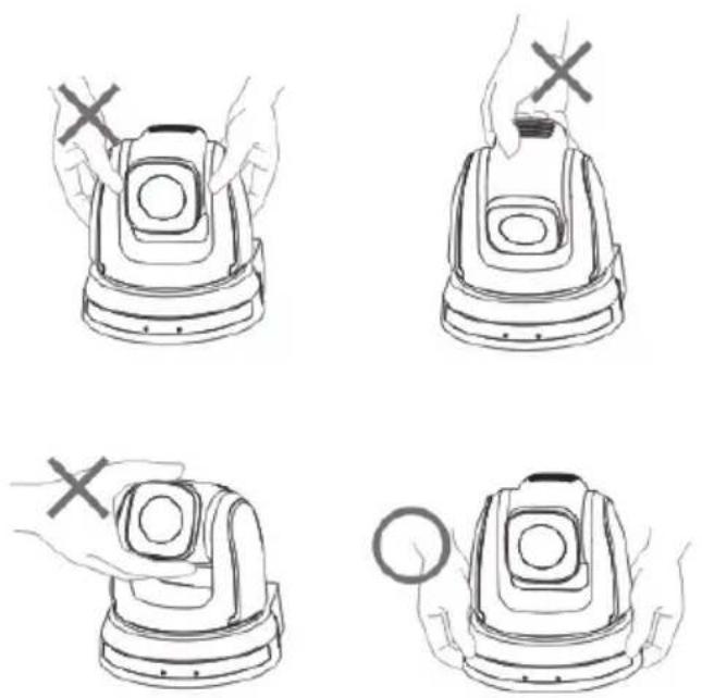
4.2.1.1 Precautions for installation
◆ Please install the machine on a flat desk
◆ Do not grab the camera head by hand when handling the device
◆ Do not rotate the camera head by hand. Improper rotation may result in breakdown of the camera
4.2.1.2 Installation steps
- Please adjust DIP switch at first prior to installation
- Place the camera on a flat desk directly to ensure the normal vertical and horizontal operation of the machine

natural_image
Illustration of a laptop and a mechanical device on a base (no text or symbols)4.2.2 I would like to install VC-A50S on the ceiling
4.2.2.1 Prepare for the parts and equipment required during the installation
- Accessories of VC-A50S in the box (metal plates A, B and M3 screw x 7)
- Screw for locking on ceiling mounted hanger x 4
- Drilling machine, screw driver, ladder
4.2.2.2 Camera Size
Length x Width x Height : 174 x 186 x 182.7 mm
Weight : 2.0 Kg
| Black | 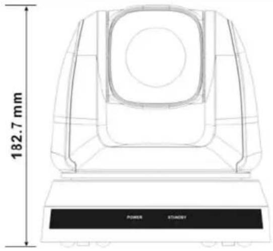 |  |
| 174 mm | 186 mm | |
| White |  |  |
| 174 mm | 186.1 mm |
4.2.2.3 Max. rotation dimension of camera
| Black White |  |
 |
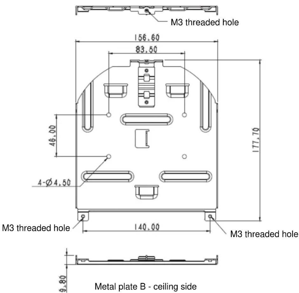
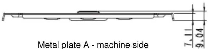
4.2.2.4 Size Diagram
1. Metal plate B - ceiling side


Metal plate B locking screw Metal plate B locking bolt
2. Metal plate A - machine side
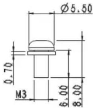
Metal plate A locking screw


- Bottom of machine

4.2.2.5 Precautions for installation
- Before installation, please confirm the orientation of the machine relative to the object to be captured
- It is recommended that the machine should be set at a distance of more than 1 meter away from the object to be captured.
Please adjust for a best distance according to the magnification of the lens

- The machine (including metal plates) is weighed at about 2.5 kg. If it is to be installed on the ceiling, please use the hanger that has obtained UL security approval to prevent the machine from falling down.
- Please check whether the camera is installed securely on a regular basis
4.2.2.6 Installation steps
-
Please adjust resolution on DIP switch at first
Please refer to Chapter 7 DIP Switch Setting for the relevant descriptions on DIP switch. -
Fix the metal plate A on the machine base with 4 M3 screws

natural_image
Technical line drawing of a mechanical component with mounting holes and internal components (no text or symbols)- Lock the metal plate B on ceiling mounted hanger
※Caution:
(1) Please use the hanger that has obtained UL security approval
(2) Please reserve the hole for the connecting wires of the camera.
- Combine the metal plate A and the metal plate B
(1) Push the metal plate A up to the ceiling and then to the right to latch the metal plate B
(2) Fix with 3 M3 screws

natural_image
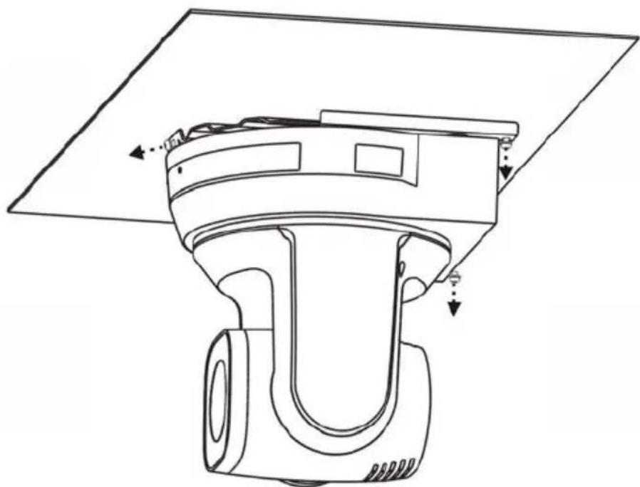
Technical line drawing of a device's internal components, showing top and side views with no text or symbols4.2.2.7 How to remove
- Remove the connecting wires from the camera
- Uninstall the camera together with the ceiling, loosen the three screws that fix the metal plates A and B and push to the left to remove the machine
natural_image
Technical line drawing of a mechanical device with no visible text or symbols- Then remove the screws on the hanger and the machine
4.3 Connecting the device
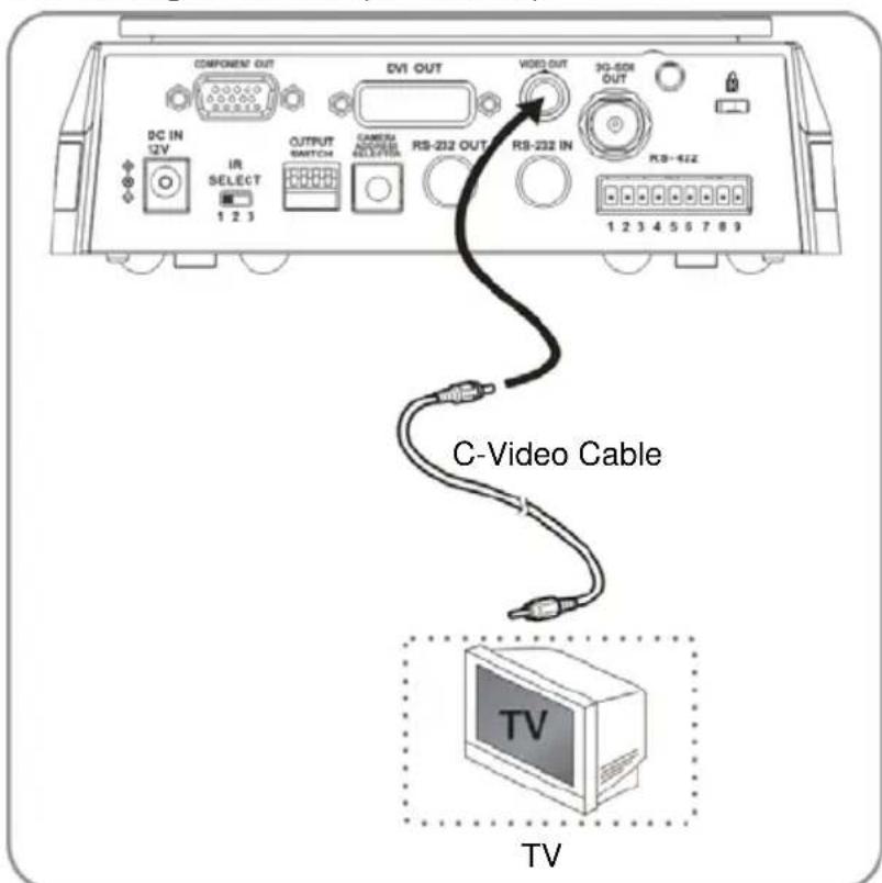
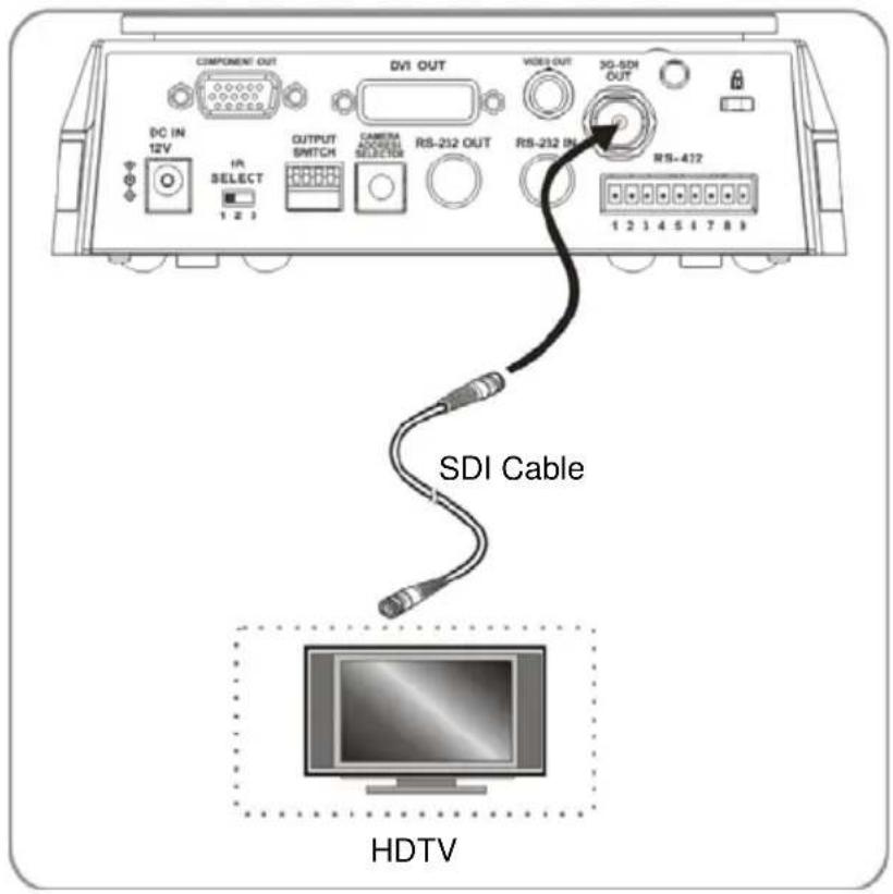
4.3.1 Image Output
4.3.1.1 Connecting to an HDTV/computer monitor (DVI)

4.3.1.2 Connecting to a TV (C-Video)
4.3.1.3 Connecting to an HDTV (3G-SDI)
4.3.1.4 Connection to the device for image output

4.3.2 Controlling VCs with the computer
4.3.2.1 Connecting to one computer for connection between VCs (RS-232 in/out)

flowchart
graph TD
    A["Computer monitor"] --> B["RS-232 IN VC-A50"]
    A --> C["RS-232 OUT"]
    A --> D["RS-232 IN VC-A50"]
    A --> E["RS-232 OUT"]
    A --> F["RS-232 IN VC-A50"]
4.3.2.2 Connecting to one computer for connection between VCs (RS-422)

flowchart
graph TD
    A["Computer monitor"] --> B["RS-422\nVC-A50"]
    B --> C["RS-422\nVC-A50"]
    C --> D["..."]
    D --> E["RS-422\nVC-A50"]
    E --> F["..."]
    F --> G["RS-422\nVC-A50"]
5.1 Functions of remote control
 | Item | Description |
| <,>,▲,▼ | Move the lens | |
| Back Light Turn on/off back light compensation | ||
| Camera select | Select 1 ~ 3 VC-A50S | |
| Focus-Manual / Far/Near | Turn on manual focus to adjust the focal length | |
| Focus-Auto | Auto focus | |
| Freeze | Freeze the screen | |
| Home-Enter Go back to the main page / Execute | ||
| Info | Status information | |
| L/R Direction Set | L/R Direction / OFF / Normal | |
| Menu | Display OSD menu | |
| Mirror Rotate the image (OFF / Mirror / Flip / Mirror + Flip) | ||
| Pan/Tilt Reset | Clear the Pan / Tilt setting | |
| Picture Switch image effect (OFF / Neg / B&W) | ||
| Power | Power Switch | |
| Preset Appoint an ID (0 ~ 9) to save the current position data | ||
| Reset Appoint an ID (0 ~ 9) to delete the current position data | ||
| Zoom-Fast Adjust image size | ||
| Zoom-Slow Fine-tune image size | ||
5.2 Setting Menu
| 1^st Level Major Items | 2^nd Level Minor Items | 3^rd Level Adjustment Values | Function Descriptions | |
| Exposure | Mode | 1. Auto2. Brightness3. Shutter Pri4. Iris Pri5. Manual | Exposure mode setting | |
| Exposure_Comp. | On/Off | AE Level | ||
| Exposure_Comp. Level | -7~C~7 | The value can be adjusted only after Exposure_Comp. is activated | ||
| Spot Light On/Off | The value can be adjusted when the mode is set to Full Auto or Shutter Pri | |||
| Spot Light Position | X(0~15)Y(0~15) | The value can be adjusted only after Spot Light is activated | ||
| Shutter Pri | 60/30 mode | 50/25 mode | Shutter priority setting | |
| 1/10000 | 1/10000 | |||
| 1/6000 | 1/6000 | |||
| 1/4000 | 1/3500 | |||
| 1/3000 | 1/2500 | |||
| 1/2000 | 1/1750 | |||
| 1/1500 | 1/1250 | |||
| 1/1000 | 1/1000 | |||
| 1/725 | 1/600 | |||
| 1/500 | 1/425 | |||
| 1/350 | 1/300 | |||
| 1/250 | 1/215 | |||
| 1/180 | 1/150 | |||
| 1/125 | 1/120 | |||
| 1/100 | 1/100 | |||
| 1/90 | 1/75 | |||
| 1/60 1/50 | — | |||
| 1/30 | 1/25 | |||
| 1/15 | 1/12 | |||
| 1/8 | 1/6 | |||
| 1/4 | 1/3 | |||
| 1/2 | 1/2 | |||
| 1/1 | 1/1 | |||
| Iris Pri | 1. F1.62. F23. F2.44. F2.85. F3.46. F47. F4.88. F5.69. F6.810. F811. F9.612. F1113. F1414. Close | Iris setting | ||
| Manual Gain | 1. 0dB2. 3.4 dB3. 6.8 dB4. 10.2 dB5. 13.7 dB6. 17.1 dB7. 20.5 dB8. 23.9 dB9. 27.3 dB10. 30.7 dB11. 34.1 dB12. 37.5dB13. 41dB14. 44.4 dB15. 47.8 dB | Manually set the gain | ||
| Manual Speed | 60/30 mode | 50/25 mode | Manually set the shutter | |
| 1/10000 | 1/10000 | |||
| 1/6000 | 1/6000 | |||
| 1/4000 | 1/3500 | |||
| 1/3000 | 1/2500 | |||
| 1/2000 | 1/1750 | |||
| 1/1500 | 1/1250 | |||
| 1/1000 | 1/1000 | |||
| 1/725 | 1/600 | |||
| 1/500 | 1/425 | |||
| 1/350 | 1/300 | |||
| 1/250 | 1/215 | |||
| 1/180 | 1/150 | |||
| 1/125 | 1/120 | |||
| 1/100 | 1/100 | |||
| 1/90 | 1/75 | |||
| 1/60 1/50 | — | |||
| 1/30 | 1/25 | |||
| 1/15 | 1/12 | |||
| 1/8 | 1/6 | |||
| 1/4 | 1/3 | |||
| 1/2 | 1/2 | |||
| 1/1 | 1/1 | |||
| Manual Iris | 1. F1.62. F23. F2.44. F2.85. F3.46. F47. F4.88. F5.69. F6.810. F811. F9.612. F1113. F1414. Close | Manually set the aperture | ||
| Bright 1~ C~28 | — | |||
| Gain Limit | 1. 10.2 dB2. 13.7 dB3. 17.1 dB4. 20.5 dB5. 23.9 dB6. 27.3 dB7. 30.7 dB8. 34.1 dB9. 37.5dB10. 41dB11. 44.4 dB12. 47.8 dB | Max. limit value of electron gain | ||
| WDR | 1. Off2. 13. 21. 3 | WDR settings | ||
| White Balance | Mode | 1. Auto2. Indoor3. Outdoor4. Trigger White Balance5. Auto White Balance6. Manual7. Outdoor Auto8. Sodium Lamp Auto9. Sodium Lamp10. Sodium Lamp Outdoor Auto | Select the color temperature mode | |
| One Push Trigger | ENTER | One push trigger | ||
| R-Gain 0~C~255 | — | Adjustable when the white balance mode is set to Manual | ||
| B-Gain 0~C~255 | — | Adjustable when the white balance mode is set to Manual | ||
| Picture | Picture effect | 1. Off2. Neg3. B&W | Set the picture effect | |
| Sharpness 1~A~16 | — | Adjust the sharpness of the image | ||
| NR | 1. Off2. 13. 24. 3_5. 46. 5 | Noise reduction setting | ||
| 3D NR | 1. Off2. Low3. Typ4. Max | 3D dynamic noise reduction settings | ||
| Saturation 0~A~14 | Adjustable when the image mode is set to Custom mode | |||
| Hue 0~ A ~14 | — | Adjustable when theimage modeis set toCustommode | ||
| Gamma | 1.12.2 | Adjustable when theimage modeis set toCustommode | ||
| Brightness 0~ A | ~31_ | Adjustable when theimage modeis set toCustommode | ||
| Contrast 0~ A ~31 | — | Contrast adjustment;Adjustable when theimage modeis set toCustom | ||
| Black Level | 1.Off2. Type 13. Type 24. Type 3 | Shadow details andtransparency adjustment,adjustable when theimage modeis set toCustom | ||
| Pan Tilt Zoom | Pan/Tilt Limit ON/Off _ | Turn on/off the angle limit setting | ||
| Pan Right Limit 0~170_ | Limit the right angle | |||
| Pan Left Limit -170~0 | Limit the left angle | |||
| Tilt UP Limit 0~90 _ | Limit the upward angle | |||
| Tilt Down Limit -30~0 | Limit the downward angle | |||
| D-Zoom Limit | x1~x12 | Limit the D-zoom multiple | ||
| Preset Speed | 1. 5 per second2. 25 per second3. 50 per second4.150 per second5. 250 per second6. 300 per second | Set the rotation speed of the cradle head when Preset is executed | ||
| Dig. -Effect | Mirror | 1.Off2. Mirror3. Flip4. Mirror + Flip | Set the mode at which the image is turned | |
| Auto Focus | AF Sensitivity | 1. Low2.Normal | Select the AF triggering speed. The higher the speed is, the faster AF is triggered | |
| AF speed | 1.Normal2. 13. 24. 35. 46. 5 | Focus speed after AF triggering | ||
| System | C-Video | NTSC LB | Image mode | |
| NTSC CP | ||||
| NTSC SQ | ||||
| PAL LB | ||||
| PAL CP | ||||
| PAL SQ | ||||
| Video Type | DVI/SDI | Select video output type | ||
| YPbPr | ||||
| Prompt On / Off | — | Turn on/off the prompt information on the display | ||
| Motionless Preset | On /Off | When the function is enabled, the screen will Freeze when Preset is executed. Freeze will be released after Preset is completed | ||
| Low Latency | On /Off | Turn on to reduce image delay | ||
| IR Receive On / Off | Turn on/off the infrared reception | |||
| Language | English / Chinese | Language | ||
| Control Device Encoder / Controller | Control Device setting | |||
| Protocol | Protocol V / Protocol PD | Protocol V: VISCAProtocol PD: PELCO D | ||
| PD Address 1~ C~255 | The Protocol set to PD allows the camera ID address to be assigned | |||
| Output Mode | 1. 1920x1080/60p2. 1920x1080/50p3. 1920x1080/30p4. 1920x1080/25p5. 1920x1080/60i6. 1920x1080/50i7. 1280x720/60p8. 1280x720/50p9. 1280x720/30p10. 1280x720/25p11. 1080/59.94p12. 1080/59.94i13. 1080/29.97p14. 720/59.94p15. 720/29.97p | |||
| Factory Reset On / Off_ | Resume the factory default setting | |||
| Status | Display the current setting status | |||
6.1 I would like to switch to VC-A50S
- Press [Camera 1 \~ 3] on the remote control to select VC-A50S.
● Camera 1 \~ 3 is selected with IR SELECT.
6.2 I would like to save the current lens position data
-
Press [Preset + ID] on the remote control to save the current position data.
-
ID shall be a digit [0 \~ 9].
- Use VISCA command to store position data to [0 \~ 127]
6.3 I would like to clear the saved position data
-
Press [Reset + ID] on the remote control to clear the given position data.
-
ID shall be a digit [0 \~ 9].
- Use VISCA command to clear position data stored in [0 \~ 127]
6.4 I would like to turn on the back light compensation function
- Press [Back Light] on the remote control to turn on or turn off the back light compensation.
6.5 I would like to adjust the shooting angle of the lens
- Press [Tilt ▲] or [Tilt ▼] on the remote control to adjust the angle upward or downward.
- Press [Pan ▶] or [Pan ◀] on the remote control to adjust the angle to right or left.
- Press [Pan - Tilt Reset] on the remote control to reset the angle to the center point.
6.6 I would like to zoom in/out images
6.6.1 Adjust image size
- Press [Fast +] on the remote control to zoom in images.
- Press [Fast -] on the remote control to zoom out images.
6.6.2 Fine-tune image size
- Press [Slow +] on the remote control to zoom in images.
- Press [Slow -] on the remote control to zoom out images.
6.7 I would like to adjust the focal length
6.7.1 Auto tune
- Press [AF] on the remote control to adjust automatically.
6.7.2 Manual focus
- Press [MF] on the remote control to turn on the manual focus function.
- Press Focus - [+] or Focus - [-] to adjust.
6.8 I would like to adjust the AF speed
6.8.1 Adjust the AF Sensitivity
Triggering speed of focus. The higher the speed is, the faster focus is triggered.
To shoot fast-moving objects, AF Sensitivity can be set to [High] or [Medium], which is applicable to quick focus.
When the environment is too dark to enable auto focus or fixed objects have to be shot in different brightness, AF Sensitivity can be set to [Low].
- Press [MENU] to activate the setting menu.
- Press [▶] or [◀] to select [Auto Focus].
-
Press [ENTER] to activate.
-
Press [▲] or [▼] to select [AF Sensitivity].
- Press [ENTER] to activate.
- Press [▶] or [◀] to select [High / Medium / Low].
- Press [MENU] to exit.
6.8.2 Adjust the AF speed
The focus speed upon triggering AF Sensitivity
● [Normal] (default): Image flickering may not occur
● [Fast]: Fast focus speed
- Press [MENU] to activate the setting menu.
- Press [▶] or [◀] to select [Auto Focus].
- Press [ENTER] to activate.
- Press [▲] or [▼] to select [AF speed].
- Press [ENTER] to activate.
- Press [▶] or [◀] to select [Fast / Normal].
- Press [MENU] to exit.
6.9 I would like to set the image mode
- Press [Picture] on the remote control to switch [OFF / Neg / B&W].
6.10 I would like to freeze images
- Press [Freeze] on the remote control to freeze the current image on the display.
6.11 I would like to rotate the image
- Press [Mirror] on the remote control to switch [Off / Mirror / Flip / Mirror + Flip].
6.12 I would like to change the camera direction
- Press [L/R Direction Set] on the remote control to switch [L/R Direction/Disable/Normal].
6.13 I would like to display the current status
- Press [Info] on the remote control to display the current status information.
7.1 DIP SWITCH
7.1.1 OUTPUT Swtich
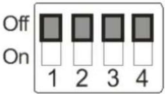
| Output Mode Setting Output Mode Setting | |||
| 1920x1080/60p 1920x1080/50p | |||
| 1920x1080/30p 1920x1080/25p | |||
| 1920x1080/60i 1920x1080/50i | |||
| 1280x720/60p 1280x720/50p | |||
| 1280x720/30p | 1280x720/25p | ||
| 1920x1080/59.94p | 1920x1080/59.94i | ||
| 1920x1080/29.97p | 1280x720/59.94p | ||
| 1280x720/29.97p | |||
7.1.2 IR SELECT

| ID Setting | |
| 1 | 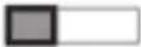 |
| 2 | 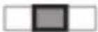 |
| 3 |  |
7.1.3 Camera Address Selector

| Setting | Function Descriptions |
| 0~7 | ID 0~7 |
| 8~9 | Reserved |
7.1.4 System Switch

| Setting Function Descriptions | |
| DIP 1 | RS-232C/RS-422 selectorOFF: RS-232C / ON: RS-422 |
| DIP 2 | Infrared signal output switchOFF: Off / ON: On |
| DIP 3 | Communication baud rate selectorOFF: 9600 / ON: 38400 |
| DIP 4 Reserved | |
7.2 RS-422 Connection
7.2.1 RS-422 Pin Description
RS-422
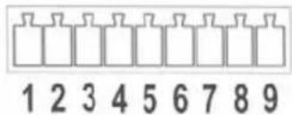
| Pin NO. Function | |
| 1 RXD OUT - | |
| 2 RXD OUT + | |
| 3 TXD OUT - | |
| 4 TXD OUT + | |
| 5 | GND |
| 6 RXD IN - | |
| 7 | RXD IN + |
| 8 TXD IN - | |
| 9 TXD IN + | |
Please connect IN+ to OUT+ when connecting to SONY products For non-SONY products, it may be necessary to connect IN+ to OUT-
7.2.2 Use RS-422 Connection
- Hold the two sides of RS-422 connector and pull out in the direction shown by the arrow in the figure below

- Peel off a section of copper wire (AWG Nos. 28 to 18) and insert it into the connector hole; then use flat screw driver to fix it

natural_image
Diagram of a connector pinout with a rotary knob and arrow indicating rotation (no text or symbols)- Insert the wired RS-422 connector back to the camera. Now the connection is completed

Chapter 8 Troubleshooting
This chapter describes problems you may encounter while using VC-A50S. If you have questions, please refer to related chapters and follow all the suggested solutions. If the problem still occurred, please contact our distributors or service center.
| No. | Problems Solutions | |
| 1. | Boot without power signal | 1. Make sure you have plugged in the power cord.2. Make sure the Service DIP switch is Off. |
| 2. | There is no image output from VC-A50S | 1. Check the power.2. Check if DIP switch is properly set. Please refer to Chapter 7 DIP Switch Setting for related settings.3. Make sure the display supports the output resolution; in general, the resolution is 1080p60/1080i60/720p60.4. Replace the cables and make sure they are not faulty. |
| 3. | VC-A50S image is severely delayed | Please use 1080p or 720p 60/50 Hz signals rather than 25/30 Hz signals. |
| 4. | Not working after changes to DIP Switch setting | After completing DIP Switch setting, unplug and reconnect the power cord and turn on the machine to change the setting. |
| 5. | VC-A50S cannot be operated by remote control | 1. Please confirm if the Camera Select on the remote control can be used together with the IR Select on VC-A50S.2. Please prevent VC-A50S from direct sunshine.3. Make sure the energy-saving bulb and the IR touch screen are as far as possible in order to avoid interference.4. When several VC-A50S are connected in the same area, the operation of two Remote Controls at the same time may result in signal interference. It is recommended to use one Remote Control. |
| 6. | The device cannot be controlled with Codec | 1. Please consult the distributor to make sure the firmware version is the latest one. The steps to check version is as follows:1.1 Press [MENU] on the remote control1.2 Choose [Status]1.3 Go to Page 5 of [System]1.4 Make sure the firmware version is correct.2. Make sure the connection is correct (RS-232/422 Input).3. Make sure System Switch DIP1 and DIP3 are correct. |
| 7. | The device cannot be controlled with RS-232/RS422 | 1. Make sure the connection is correct (RS-232/422 Input).2. Make sure System Switch DIP1 and DIP3 are correct. |


- Installation Guide - English
- [Important]
- Table of Contents
- Copyright Information......3
- Chapter 1 Safety Instructions ....4
- Chapter 2 Package Contents....7
- Chapter 3 Product Overview ...... 8
- Chapter 4 Instruction for Installation ...... 9
- Chapter 5 Remote Control and Setting Menu....22
- Chapter 6 Descriptions of Major Functions....31
- Chapter 7 DIP Switch Setting....35
- Chapter 8 Troubleshooting....39
- ■ Precautions
- ■ FCC Warning
- ■ KCC Warning
- Chapter 2 Package Contents
- Overview
- Description of LED indicator
- Power:
- Standby:
- Preparation before installation
- Instruction for installation
- I would like to install VC-A50S on the desk
- Installation steps
- I would like to install VC-A50S on the ceiling
- Prepare for the parts and equipment required during the installation
- Camera Size
- Max. rotation dimension of camera
- Size Diagram
- Metal plate B - ceiling side
- Metal plate A - machine side
- Precautions for installation
- Installation steps
- How to remove
- Connecting the device
- Image Output
- Connecting to an HDTV (3G-SDI)
- Connection to the device for image output
- Controlling VCs with the computer
- Functions of remote control
- Setting Menu
- I would like to switch to VC-A50S
- I would like to save the current lens position data
- I would like to clear the saved position data
- I would like to turn on the back light compensation function
- I would like to adjust the shooting angle of the lens
- I would like to zoom in/out images
- Adjust image size
- Fine-tune image size
- I would like to adjust the focal length
- Auto tune
- Manual focus
- I would like to adjust the AF speed
- Adjust the AF Sensitivity
- Adjust the AF speed
- I would like to set the image mode
- I would like to freeze images
- I would like to rotate the image
- I would like to change the camera direction
- I would like to display the current status
- DIP SWITCH
- OUTPUT Swtich
- IR SELECT
- Camera Address Selector
- System Switch
- RS-422 Connection
- RS-422 Pin Description
- Use RS-422 Connection
- Chapter 8 Troubleshooting
Brand : Lumens
Model : VC-A50SB
Category : Security Camera