
ADDAC210 - Unknown ADDAC System - Free user manual and instructions
Find the device manual for free ADDAC210 ADDAC System in PDF.


| Product Type | Eurorack Synthesizer Module |
| Brand | ADDAC System |
| Model | ADDAC210 |
| Width | 8 HP |
| Depth | 30 mm (including power cable) |
| Weight | 120 g |
| Power Supply | +12V: 50 mA, -12V: 40 mA (via Eurorack bus board) |
| Module Type | CV Processor / Utility |
| Main Functions | Voltage processing, attenuation, offset, mixing, and signal routing |
| Inputs | 4 CV inputs (3.5 mm jacks, DC-coupled) |
| Outputs | 4 CV outputs (3.5 mm jacks, DC-coupled) |
| Controls | 4 knobs for attenuversion, switches for offset/attenuator mode |
| Indicators | LED per channel for signal activity or clipping |
| Construction | Skiff-friendly, aluminum faceplate, steel chassis |
| Included Accessories | M3 screws, power ribbon cable |
| Power Connection | 10-pin Eurorack power header, reverse polarity protection |
| Warranty | 2 years limited against manufacturing defects |
| Certifications | RoHS compliant |
| Maintenance | Clean with dry cloth; avoid liquids |
| Safety | Do not expose to moisture or extreme temperatures |
| Repairability | Spare parts available via ADDAC System; user-serviceable fuses |
Frequently Asked Questions - ADDAC210 ADDAC System
User questions about ADDAC210 ADDAC System
0 question about this device. Answer the ones you know or ask your own.
Ask a new question about this device
Download the instructions for your Unknown in PDF format for free! Find your manual ADDAC210 - ADDAC System and take your electronic device back in hand. On this page are published all the documents necessary for the use of your device. ADDAC210 by ADDAC System.
USER MANUAL ADDAC210 ADDAC System
DISCLAIMER
We do not take any responsibility and we are not liable for any damage caused while using this module, be it indirect, special, incidental or consequential damages (including but not limited to damages to power supplies, other modules, personal computers or to the module itself).
Use it at your own responsibility!
REMARKS ON SAFETY
(For the electronic enthusiast)
There are a few things to be very aware while using this module, will try to put it simple here, bottom line is if you're not sure of what you're doing s#!t will happen, but don't despair s#it will also happen when you think you know what you're doing!
However, this means that when something is not right, best case scenario, your circuit is somehow faulty and it simply doesn't work or, worst case scenario, your circuit is faulty, it won't work but it will also create some sort of "short circuit" that will carry a high load through the module and demand a higher current from the PSU to where it's connected. This doesn't mean that all mistakes will be short circuits, but this is the worst case scenario walkthrough.
When a short circuit happens, all the load goes through the components in the circuit and ultimately will drain the PSU to its limits. Depending on the PSU you may have different things will happen.
Our PSUs, being good quality switching PSUs, offer short circuit and over-current protection and they will simply shutdown until the short circuit is removed. On the other hand, if working with Toroidal PSUs they will drop they're operating voltage and provide as much current as they physically can, this can be harmful for other modules connected in the same PSU as well as to the PSU itself.
So, how can we be safe at all times?
Simple, make "no" mistakes! Easy right? From experience most times i learned "The" lesson was when i burnt/busted/broke/smoked something. Most of those times i wasn't too focused either, so never be careless, always try to be thinking ahead preventing "catastrophes" from happening.
So if you're stepping into electronics for the first times, be very aware at all times, keep one hand close to the off switch! And keep an eye on the status leds, specially when making new circuit connections and at power ups!
Be aware of board and components temperature, first sign of bad circuit design is heat, if something is heating up than most probably it will burn out soon, raise your nose awareness up, although things normally start to smell funny a bit too late, and if you see smoke than that part is already gone for good.
If you're learning the arduino platform by it's own or working solely on the arduino side, keep the open heart disconnected from the modular, you can safely work with the usb power and avoid other mistakes.
ADDAC210 OPEN HEART SURGERY
USER'S GUIDE
August.2014Revision.01
OVERVIEW
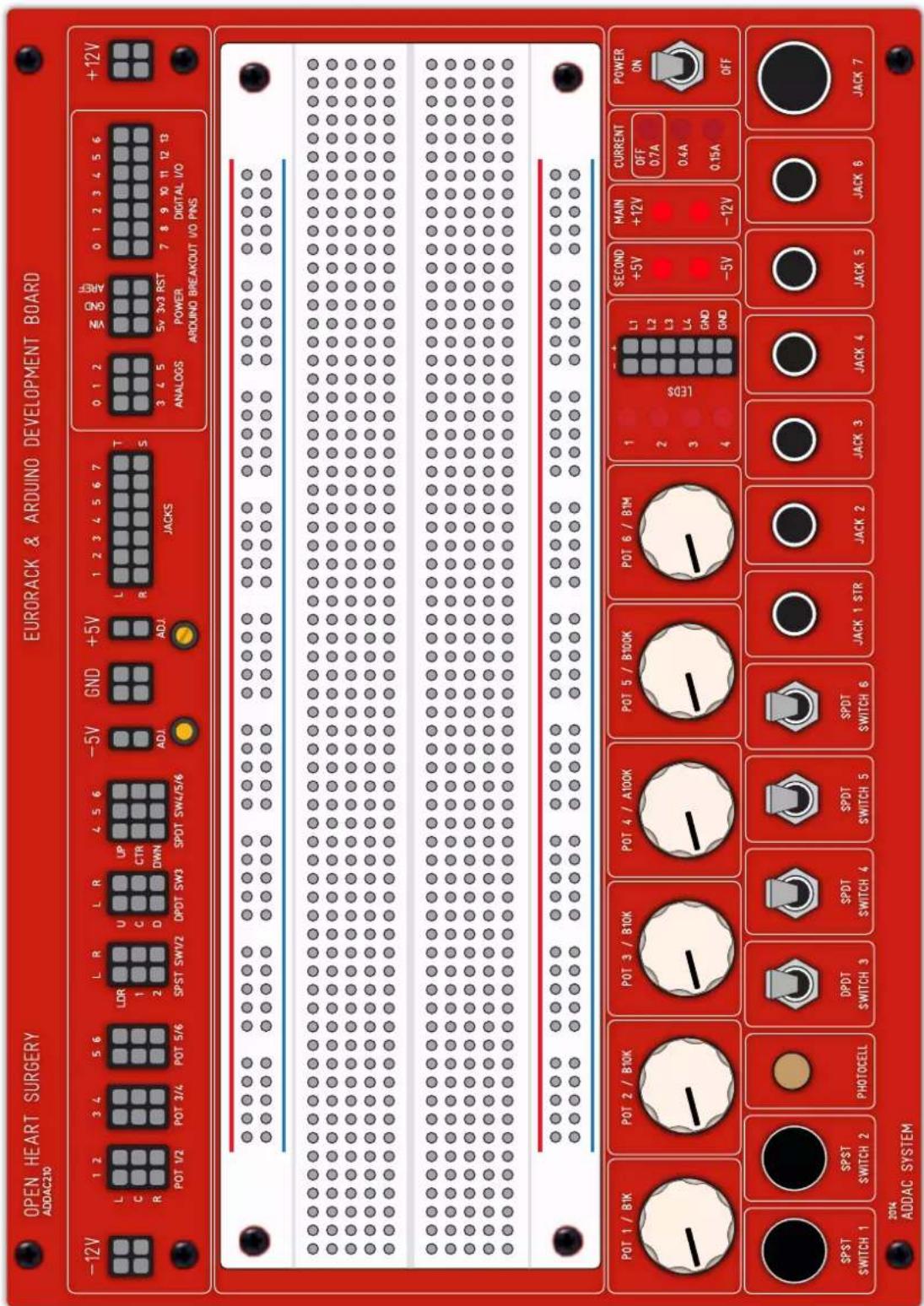
This is a development platform optimized for the Eurorack electronic enthusiast.
.Frontpanel parts:
On/Off Power switch
1x breadboard
1x 1K Pots
2x 10k Pot
1x 100k Log Pot
1x 100k Pot
1x 1M Pot
4x Leds
1x Photocell
2x SPST (normally open) push switches
1x DPDT (on/on) toggle switch
1x SPDT (on/on) toggle switch
2x SPDT (on/off/on) toggle switches
1x 3.5mm stereo jack
5x 3.5mm mono jack
1x 1/4" mono jack

Power sources:
-12V, +12V
-3/10V. +3/10V
Ships with:
1M Ribbon Cable and 55cm standoff Spacers for desktop operation.
1 Extra breadboard
Screws and nylon washers
Mechanical Specs:
Width: 36 HP
Depth: 3.5cm (±1.375 inches) with or without Arduino installed. Depth increases if using arduino shields.
ADDAC210 OPEN HEART SURGERY
USER'S GUIDE
August.2014Revision.01
POWER DIAGRAM
In order to understand how the power diagram works, consider 4 different power sources:
MAIN POWER
Main power is the power coming from your Bus Board
FRONTPANEL POWER
This is the power source that will be used throughout the module. This voltage is Post the On/Off Switch and Post protection relays. Due to the current protection circuit there's a small voltage drop from the Main Power
SECONDARY POWER
These are 2 extra power sources, a positive and a negative one, they can be adjusted by the adjacent trimmers to any voltage between +3V to +10V and -3V to -10V.
ARDUINO POWER
The Arduino Power Pins are completely independent from all other sources. These pins are active only if an arduino is plugged in and powered by an USB cable or an external power adapter.
PATH DESCRIPTION
The Main voltage coming from your Bus Board goes through the On / Off Switch to the current detection circuit and then through the Solid State Relays into the Front panel power.
The secondary voltage is taken from the Front panel power and goes through 2 voltage regulators (317 & 337) and into the Frontpanel Secondary Power Pins.
If the current detection circuit reaches its threshold it will activate the Solid State Relays and turn off all Frontpanel power sources excluding the Arduino Power Pins.

flowchart
graph TD
    A["MAIN POWER"] --> B["ON / OFF SWITCH"]
    B --> C["CURRENT DETECTION"]
    C --> D["SOLID STATE RELAYS"]
    D --> E["FRONT PANEL POWER PINS ±11.8V"]
    E --> F["ADJUSTABLE SECONDARY POWER PINS (default: ±5V)"]

    G["+12V"] --> H["ARDUINO POWER PINS"]
    G --> I["SECONDARY POWER ADJUST TRIMMERS ±3V to ±10V"]
    G --> J["-12V"]

    style A fill:#f9f,stroke:#333
    style H fill:#ccf,stroke:#333
    style I fill:#cfc,stroke:#333
    style J fill:#fcc,stroke:#333
ADDAC210 OPEN HEART SURGERY
USER'S GUIDE
August.2014Revision.01


POWER SWITH & MONITOR LEDS
There are 7 Leds and 1 Switch on the front panel.
The Power On/Off Switch is self-explanatory, it turns the power On or Off. This switch is also used to reset the current protection switch once the Protection Relays have been activated.
The Leds are separated into 3 groups: SECOND*
These Leds shows the status of the Secondary power sources.
MAIN*
These Leds shows the status of the Main power sources.
* WARNING: If any of these Leds are off you should immediately turn the Power Switch to Off!
CURRENT
These Leds shows the status of the Current detection circuit.
When top led is on (OFF) means that the main power has been shutdown and needs to be Reset with the Power On/Off switch.
The labels on the Front panel are relative, there's a trimmer on the right side to adjust the max current consumption before shutdown.
ADDAC210 OPEN HEART SURGERY
USER'S GUIDE
August.2014Revision.01
POTENTIOMETERS
There are 6 Potentiometers on the front panel, the resistance values of the pots are:
1: B1K
2: B10K
3: B10K
4: A100K
5: B100K
6:1M
(A is for logarithmic pots, B for linear ones)
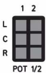
The connections for all pots are in the female pinheaders at the top.
Horizontally you can access all pots 1 to 6.
Vertically you access each specific pot pins: Left / Center / Right.


LEFT
CENTER
RIGTH


ADDAC210 OPEN HEART SURGERY
USER'S GUIDE
August.2014Revision.01
SWITCHES & PHOTOCELL
There are 6 Switches and 1 Photocell on the front panel.
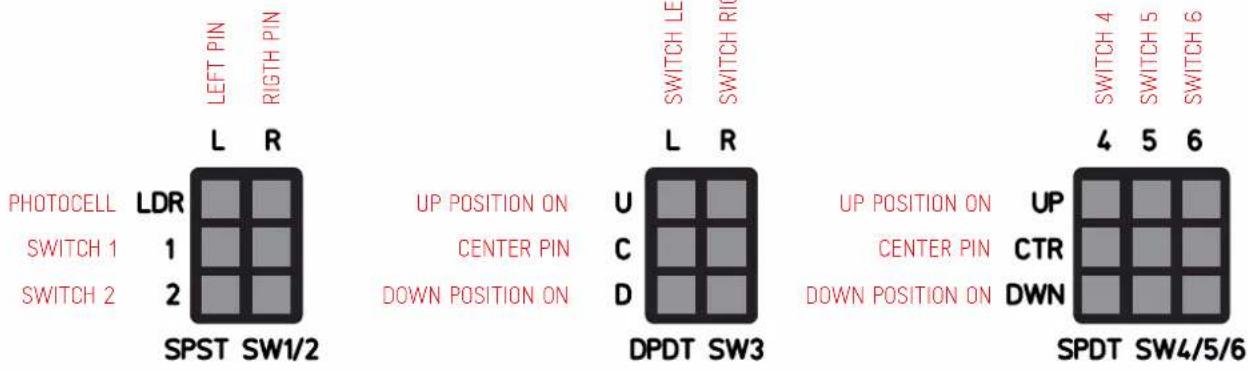
There are 3 different switch types:
1 & 2: SPST, Off - On
3: DPDT, On - On
4 to 6: SPDT, On - Off - On
The connections for all switches are in the female pinheaders at the top.
label indicate switch position: Up / Center / Down.
Note that this is different from standard switches connections as due to the switch mechanics normally this would be connected the other way around.

ADDAC210 OPEN HEART SURGERY
USER'S GUIDE
August.2014Revision.01

JACKS
There are 6 Switches and 1 Photocell on the front panel.
There are 3 different switch types:
1 & 2: SPST, Off - On
3: DPDT, On - On
4 to 6: SPDT, On - Off - On
The connections for all Jacks are in the female pinheaders at the top.
label indicate switch position: Up / Center / Down.
Besides Jack 1, all jacks have Tip, Tip Switch and Ground.
STEREO JACK 1 MONO JACKS 2 to 7

ADDAC210 OPEN HEART SURGERY
USER'S GUIDE
August.2014Revision.01

LEDS
There are 4 Leds on the front panel.
The connections for all Leds are in the female pinheaders besides them.
label indicate led leg:
(-) Minus or cathode
(+) Positive or anode
For convenience there are also 4 Ground points at the bottom of the female header.

ADDAC210 OPEN HEART SURGERY USER'S GUIDE
August.2014Revision.01
HARDWARE SETTINGS
natural_image
Diagram of a mechanical or electronic component with highlighted blue and yellow components, no visible text or symbolsCURRENT TRIMMER
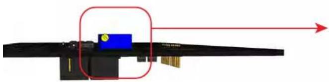
There's one trimmer on the right side of the module to adjust the shutdown threshold. This can be set from 0.2A to 0.8A. For safety default maximum current is 0.3A

The module ships with all these pins disconnected. The 5V and 3V3 jumper, determines if the Arduino 5V/3V3 will go to the frontpanel female header, if not present 5V/3V3 will not be present in the frontpanel.
GND jumper shares the Ground between the synth power supply and the Arduino.
ADDAC210 OPEN HEART SURGERY
USER'S GUIDE
August.2014Revision.01
ARDUINO COMPATIBILITY
This module stacks on top of an Arduino just like any standard Arduino shield. It is compatible with Arduino Diecimila, Duemilanove and Uno type of boards.
It's also possible to use certain Arduino shields stacked between the Arduino and the module.
For an ultimate safe use, we deeply recommend the RUGGEDUINO, this is a 3rd party board developed to be practically indestructible, it features over voltage and over current protection which will keep your board and ultimately your computer safe at "all" times! http://www.ruggedcircuits.com/microcontroller-boards/ruggeduino
ADDAC210 OPEN HEART SURGERY
USER'S GUIDE
August.2014Revision.01
ADDAC210 OPEN HEART SURGERY
USER'S GUIDE
August.2014Revision.01
- DISCLAIMER
- REMARKS ON SAFETY
- ADDAC210 OPEN HEART SURGERY
- OVERVIEW
- POWER DIAGRAM
- MAIN POWER
- FRONTPANEL POWER
- SECONDARY POWER
- ARDUINO POWER
- PATH DESCRIPTION
- POWER SWITH & MONITOR LEDS
- CURRENT
- POTENTIOMETERS
- SWITCHES & PHOTOCELL
- JACKS
- LEDS
- ADDAC210 OPEN HEART SURGERY USER'S GUIDE
- HARDWARE SETTINGS
- CURRENT TRIMMER
- ARDUINO COMPATIBILITY
Brand : ADDAC System
Model : ADDAC210
Category : Unknown