VJ-1638 - Printer Mutoh - Free user manual and instructions
Find the device manual for free VJ-1638 Mutoh in PDF.

User questions about VJ-1638 Mutoh
0 question about this device. Answer the ones you know or ask your own.
Ask a new question about this device
Download the instructions for your Printer in PDF format for free! Find your manual VJ-1638 - Mutoh and take your electronic device back in hand. On this page are published all the documents necessary for the use of your device. VJ-1638 by Mutoh.
USER MANUAL VJ-1638 Mutoh
natural_image
Line drawing of a large industrial printing press machine with control panel and wheels (no text or symbols)Read This Manual Before Using The Printer.
Rev.
VJ1638xE-A-01
Important Notice
1. For Users in Europe

The CE marking is a mandatory European marking for certain product groups to indicate conformity with the essential health and safety requirements set out in European Directives.
By affixing the CE marking, the manufacturer, his authorized representative, or the person placing the product on the market or putting it into service ensures that the item meets all the essential requirements of all applicable EU directives and that the applicable conformity assessment procedures have been applied.
2. For Users in the United States
This equipment has been tested and found to comply with the limits for a Class A digital device, pursuant to Part 15 of the FCC Rules.
These limits are designed to provide reasonable protection against harmful interference when the equipment is operated in a commercial environment.
This equipment generates, uses, and can radiate radio frequency energy and, if not installed and used in accordance with the instruction manual, may cause harmful interference to radio communications.
Operation of this equipment in a residential area is likely to cause harmful interference in which case the user will be required to correct the interference at his own expense.
3. Trademark Mentioned in this Manual
- MUTOH, ValueJet, VJ-1638, VJ-1638W, MH-RTL are registered trademarks or product names of MUTOH INDUSTRIES LTD.
- Windows XP, Windows Vista, Windows 7, Windows Server 2003 and Windows Server 2008 are registered trademarks or product names of Microsoft Corporation.
- Other company and product names may be registered trademarks or product names.
NOTE
- No part of this product or publication may be reproduced, copied, or transmitted in any form or by any means, except for personal use, without the permission of MUTOH INDUSTRIES LTD.
- The product and the contents of this publication may be changed without prior notification.
- MUTOH INDUSTRIES LTD. has made the best efforts to keep this publication free from error, but if you find any uncertainties or misprints, please call us or the shop where you bought this equipment.
- MUTOH INDUSTRIES LTD. shall not be liable for any damages or troubles resulting from the use of this equipment or this manual.
Warranty Limitations
-
MUTOH INDUSTRIES LTD. warrants part repair or replacement as a sole measure only if a failure is found in the system or in the materials and workmanship of the product the seller produced. However, if the cause of failure is uncertain, decide the action after due mutual consultation. Details concerning the warranty are written in the warranty certificate included with the product.
-
The warranty shall not apply to any direct or indirect loss, or compensation for the loss due to the product that has been subject to misuse, neglect, or improper alternation.
About this Manual
1. Contents of the Manual
There are three manuals for this product.
Installation manual
Explains operating procedures along with unpacking, installation and preparation before use.
Operation Manual (this manual)
2. Purpose and Target Readers
This manual explains preparations before use and operation procedures for MUTOH Full Color Ink Jet Printer VJ-1638/1638W.
This manual is prepared for the owners and operators of this printer.
Before using this printer, fully understand the contents and directions in this manual.
3. Manual Configuration
| Section Description | |
| 1 Safety instructions | This chapter explains the installation of this printer, warning terms that operators need to know, caution items and warning labels on the printer main unit. |
| 2 Product overview | This chapter explains the features of the printer along with the names and functions of each part. |
| 3 Before using | This chapter explains necessary steps before using the printer. |
| 4 Handling the printer This chapter explains how to handle the printer. | |
| 5 Panel setup menu The section explains the Setup menu of the printer. | |
| 6 Maintenance This chapter describes daily maintenance of the product. | |
| 7 Troubleshooting | This chapter describes possible troubles during the use of this product and countermeasures. |
| 8 Appendix | This chapter describes specifications and included components with this printer. |
NOTE
- "1 Safety instructions" to "4 Handling the printer" must be read before using the printer.
- Read "5 Panel setup menu" through "8 Appendix" as necessary.
4. Manual Notation
This section explains general cautions that must be followed in order to use this printer safely.
| Warning Meaning | |
 WARNING WARNING | Used for dangerous situations where death or serious injury may be caused. |
 CAUTION CAUTION | Used for dangerous situations that may cause slight or medium injury, or when all or parts of products are damaged. |
 | It is used for special cautions and for information that needs to be emphasized. |
 | Indicates useful tips for operating or understanding the printer. |
 | Indicates "prohibited" operations. |
 | Indicates required operations. |
 | Indicates reference pages in this manual. |
GENERAL TABLE OF CONTENTS
1 Safety instructions
1.1 Types and meanings of warnings 1-2
1.2 Important safety instructions.... 1-3
1.3 Warning labels.... 1-7
1.3.1 Handling the warning labels 1-7
1.3.2 Location and type of warning labels 1-8
1.3.2.1 VJ-1638 Warning labels ..... 1-8
1.3.2.2 VJ-1638W Warning labels .....1-10
2 Product overview
2.1 Features.... 2-2
2.2 Names of parts and functions 2-3
2.2.1 Front section.... 2-3
2.2.2 Rear section 2-5
2.2.3 Operation panel 2-6
2.3 Printer status outline 2-10
2.3.1 Status 2-10
2.3.2 Changing printer status.... 2-10
3 Basic usage
3.1 Power cord set connection 3-2
3.2 Turning the power ON/OFF 3-6
3.2.1 Turning the power ON 3-6
3.2.2 Turning the power OFF.... 3-7
3.3 Filling ink 3-9
3.3.1 When using 220ml Ink cartridges 3-10
3.3.1.1 For VJ-1638 3-11
3.3.1.2 For VJ-1638W 3-16
3.3.2 When using 440ml Ink cartridges (VJ-1638 only) 3-23
3.3.3 Changing the angle of Ink cartridge slot 3-29
3.3.3.1 When inserting Ink cartridges vertically 3-29
3.3.3.2 When inserting Ink cartridges horizontally ..... 3-30
3.3.4 Installing High Capacity Ink Pack Adapter (option) for VJ-1638 only ..... 3-32
3.3.5 When using High-capacity ink pack adapter for the first time on the printer whose ink is filled.... 3-38
3.4 Loading media....3-39
3.4.1 Loading roll media 3-39
3.4.2 Setting Roll Media 3-44
3.4.3 Setting the User Type Setting. 3-52
3.4.4 Changing Torque of Roll Media Holder 3-54
3.5 Test print....3-56
3.5.1 Nozzle check 3-59
3.5.2 Mode print.... 3-60
3.5.3 Setup print 3-61
3.5.4 Palette print 3-62
3.6 Print quality adjustment....3-63
3.6.1 Standard print quality adjustment 3-63
3.6.1.1 Standard confirmation pattern 3-64
3.6.1.2 Standard rough adjustment pattern 3-69
3.6.1.3 Standard micro adjustment pattern 3-73
3.6.2 Custom print quality adjustment 3-78
3.6.2.1 Custom confirmation pattern 3-79
3.6.2.2 Custom rough adjustment pattern 3-84
3.6.2.3 Custom micro adjustment pattern 3-88
3.6.2.3.1 Adj. PatternALL.... 3-88
3.6.2.3.2 Individual Adj. pattern 3-93
3.7 Connecting the printer to PC....3-98
3.7.1 System requirements 3-98
3.7.2 Preparing cables.... 3-98
3.7.3 Connecting a network interface cable 3-99
4 Daily maintenance
4.1 Print flow chart 4-2
4.2 Media 4-4
4.2.1 Media type 4-4
4.2.2 Cautions on handling media 4-5
4.2.3 Precaution on storing media. 4-5
4.2.4 Printable area 4-6
4.2.5 Head height adjustment 4-6
4.2.5.1 When setting the head height to Mid 4-6
4.2.5.2 When setting the head height to High 4-8
4.2.5.3 When setting the head height to Low. 4-10
4.2.6 Media feed compensation 4-11
4.2.6.1 Procedure for the media feed compensation value 4-11
4.2.6.2 How to fix the media firmly 4-17
4.2.7 Installing Media holder plates 4-18
4.3 Menu setups on Operation panel .....4-21
4.3.1 Menu setup procedure 4-21
4.3.2 Panel setup menu overview 4-23
4.4 Operating from Operation panel 4-24
4.4.1 Feeding media 4-24
4.4.2 Stopping printing operation.... 4-25
4.4.3 Cutting media 4-26
4.4.4 Cutting media manually 4-27
4.4.5 Changing and confirming settings while printing 4-29
4.4.5.1 Procedure for changing and confirming settings while printing ..... 4-29
4.4.5.2 Settings that can be changed or confirmed while printing .....4-30
4.4.6 Pausing printing 4-30
4.4.7 Starting printing during warming up (VJ-1638 only) 4-31
4.5 Using Spectrophotometer (VJ-1638 only). 4-33
5 Troubleshooting
5.1 Setup menu 5-2
5.1.1 User Type menu 5-4
5.1.1.1 User Type advanced setup menu 5-4
5.1.1.1.1 Print Mode menu....5-6
5.1.1.1.2 Adjust Print menu ..... 5-9
5.1.1.1.3 Media feed compensation....5-11
5.1.1.1.4 Pre-heater menu (VJ-1638 only)....5-13
5.1.1.1.5 Platen Heater menu (VJ-1638 only) .....5-14
5.1.1.1.6 Dryer menu (VJ-1638 only). 5-15
5.1.1.1.7 Vacuum Fan menu . . . . . . . . . . . . . . . . . . . . . . . . . . . . . . . . . . . . . . . . . . . . . . . . . . . . . . . . . . . . . . 5-15
5.1.2 Spitting menu 5-16
5.1.2.1 Spitting Pass Count menu .....5-17
5.1.3 Side Margin menu. 5-19
5.1.4 Media Set menu 5-20
5.1.5 Media Width menu 5-20
5.1.6 Output Mode menu 5-22
5.1.6.1 Ink Dry Time menu....5-22
5.1.7 Method of Cut menu 5-23
5.1.8 Origin menu 5-23
5.1.9 Prev. Stick menu (VJ-1638 only) 5-25
5.1.10 Standby Heating menu (VJ-1638 only). 5-25
5.1.11 Head Travel menu 5-26
5.1.12 Multi Strike menu 5-26
5.1.13 Strike Wait menu 5-27
5.1.14 Slant Check menu 5-27
5.1.15 Auto Cleaning menu 5-28
5.1.15.1 Idle Auto Cleaning 5-28
5.1.15.2 Printing Mode Auto Cleaning .....5-29
5.1.15.3 Pre-printing Mode Auto Cleaning 5-29
5.1.16 Ink Status menu 5-29
5.1.17 Roll Length menu 5-30
5.1.17.1 Roll Length menu 5-30
5.1.18 Exhaust Fan menu 5-31
5.1.19 Longstore menu 5-31
5.1.20 CR Maintenance menu 5-32
5.1.21 Initialization menu 5-32
5.1.22 Life Times menu 5-33
5.1.23 IP Address menu 5-33
5.1.24 Subnet Mask menu.... 5-34
5.1.25 Gateway menu 5-34
5.2 Test Print Menu....5-35
5.3 Cleaning menu ....5-36
5.4 Menu Option menu....5-37
5.5 Version menu ....5-40
5.6 Sleep Mode menu....5-41
5.6.1 Timer Setting menu 5-42
5.6.2 Sleep Mode Start menu 5-43
5.7 Display menu....5-44
5.7.1 Language menu 5-44
5.7.2 Temperature menu 5-44
5.7.3 Length menu.... 5-45
6 Maintenance
6.1 Replacing consumable components 6-2
6.1.1 Replacing Ink cartridges 6-2
6.1.2 Replacing Roll Media 6-10
6.1.3 Replacing Flushing box sponges 6-12
6.1.4 Replacing Cutter.... 6-18
6.2 Cleaning the printer 6-28
6.2.1 Cleaning the outer case 6-29
6.2.2 Cleaning the inside of the printer 6-29
6.2.3 Head cleaning.... 6-33
6.2.4 Cleaning Cleaning wiper.... 6-34
6.2.5 Cleaning the circumference of Print head 6-40
6.3 Disposal of waste fluids....6-47
6.4 Moving or transporting the printer 6-50
6.4.1 Moving the printer.... 6-50
6.4.2 Transporting the printer 6-52
7 Troubleshooting
7.1 Malfunctions and failures....7-2
7.1.1 Problems in installation and introduction 7-2
7.1.2 Cannot print at all 7-3
7.1.3 Media-related troubleshooting 7-4
7.1.4 Printing-related troubleshooting 7-6
7.2 Error messages.... 7-9
7.2.1 Status messages 7-9
7.2.2 Message type error display and remedies 7-11
7.2.3 Error requiring restart 7-14
7.3 The media is jammed 7-15
8 Appendix
8.1 Product specifications 8-2
8.1.1 Printer specifications.... 8-2
8.2 Interface specification 8-4
8.2.1 Network interface specification 8-4
8.3 Options/Supply list 8-5
1 Safety instructions
This chapter explains the installation of this printer, warning terms that operators need to know, caution items and warning labels on the printer.

WARNING
- When installing and operating this printer, be sure to follow the directions and warnings in this manual.
1.1 Types and meanings of warnings
The warnings in the Operation Manual and the warning labels attached to the printer are categorized into three stages.
Understand the meanings of the following warning terms and follow the contents (instructions) in this manual.
| Warning Meaning | |
 | Used for dangerous situations where death or a serious injury may be caused. |
 | Used for dangerous situations that may a cause slight or medium injury, or when all or parts of the products may be damaged. |
 | Used for special cautions and for information that needs to be emphasized. |
1.2 Important safety instructions
This section explains general cautions that must be followed in order to use this printer safely.

WARNING

Do not install this printer in the following places. It may cause an injury if the printer falls down.
- On a shaky stand
- Slanting location
- Places where vibration of other machines etc. is transmitted

Do not climb on the printer or place heavy things on top of it. It may cause an injury if the printer falls down.

Do not block the vent when covering the printer with cloths, such as a blanket or tablecloth. If the vent is blocked, heat may accumulate inside the printer and may cause a fire.

Do not install the printer where it is humid or dusty. It could lead to an electric shock or fire.

Do not use a damaged power cord set. It could lead to an electric shock or fire.

Do not pull out or insert the power plug with a wet hand. This could lead to an electric shock.

Do not connect an earth wire to the following places.
- Gas pipes
There is a possibility of ignition and explosion. - Earth wire of telephone cables and lightning rods A heavy current might flow whenever lightning strikes.
- Water pipe and faucet The earth might not work if a plastic pipe is connected in the middle of the metal pipe.

Do not insert or drop metal or flammable objects into the printer through openings such as a vent. It could lead to an electric shock or fire.

If foreign substances or liquids such as water entered the printer, do not use the printer as it is. It could lead to an electric shock or fire. Immediately turn OFF the power switch, disconnect the power plug from the electric socket, and contact your local MUTOH dealer.

Wire the various cords as directed in the Operation Manual. Wrong wiring could cause a fire.

Be sure to use the specified power cord set. Using a power cord set other than the specified can cause an electric shock or fire.

Make sure to use only the specified power supply (AC 100 V to 120 V or AC 220 V to 240 V). If a power supply other than the specified voltage is used, it could cause an electric shock or fire.

Take power for the printer directly from the power socket (AC 100 V - 120 V or AC 220 V - 240 V). Do not use multiple plugs on the same socket. This could generate heat and might cause a fire.

Be sure to use a dedicated power socket with an earth wire for the power supply, and connect it to the earth wire. If the earth wire is not connected, it may cause an electric shock or fire.

You are obligated to properly dispose of waste fluid from the printer in compliance with Wastes Disposal and Public Cleansing Act and local ordinances. Delegate disposal to an industrial waste disposal contractor.

Do not place any combustible materials on the platen while the heater is working. There may be a risk of fire.

Do not spill flammable liquid on the platen. It may cause a fire.

CAUTION

Pay attention to the following points when handling the power cord set.
- Do not tamper with the power cord set.
- Do not put heavy objects on the power cord set.
- Do not bend, twist or pull the power cord set by force.
- Do not route the power cord set near heating appliances.

Pay attention to the following points when handling the power plug. Any mishandling of the power cable could cause a fire.
- Make sure that no foreign substances such as dust are stuck to the power plug.
- Make sure that the power plug is firmly inserted to the edge of the power socket.

When handling Ink cartridges, pay attention so that ink does not come into contact with your eyes or skin. If ink gets into your eyes or sticks to your skin, immediately wash it off with water. Failing to do so might cause irritation or light inflammation of eyes. In case of any abnormality, consult a physician immediately.
Do not disassemble Ink cartridges.
If disassembled, there is a possibility that ink might come into contact with your eyes or skin.

Do not operate Media loading lever during initial operation. Print head may touch Pressurizing roller and cause a malfunction.
Do not use volatile solvents such as thinner, benzene, or alcohol. These solvents may cause damage to the paint.

Make sure that no moisture enters the printer. The electric circuit inside the printer may be short-circuited.

Never open covers attached using screws under any circumstances. This may cause an electric shock or a malfunction.

Do not spill waste fluid when replacing Flushing-box sponges. If waste fluid comes into contact with Grid roller, it may damage its surface and affect media feeding.


When cleaning Ceaning wiper,
- Do not touch Cleaning wiper and Head cap unit.
Head cleaning may not be performed correctly because of oil from your hands.
• Make sure to use Cleaning stick to wipe Print head.
A wet Cleaning stick may cause Print head to clog. - Do not reuse Cleaning stick.
The attached dust, etc may damage Print head.

When cleaning around Print head,
- Never touch the nozzles of Print head.
Doing so may damage Print head. - Do not touch the tip of Cleaning stick.
Print head may be damaged because of oil from your hands. - Never put water, etc on the tip of Cleaning stick.
Doing so may damage Print head. - Do not reuse Cleaning stick.
The attached dust, etc may damage Print head.

Do not slant the printer, prop it against a wall or turn it upside down.
The ink inside the printer may leak.
Moreover, normal operation after shifting (to these positions) cannot be guaranteed.

Unpacking or moving this printer must be done by the following number of people.
- More than 4 people

Installing the dedicated stands on the printer must be done by the following number of people.
- More than 4 people

When taking the printer out of the container box, make sure to remove the vinyl, install Reinforcement for transportation, and hold Reinforcement.
If lifting up the printer with the vinyl on, there is a possibility the printer can slip and drop, and be damaged.

When you do not use the printer for a long period, make sure to pull out the power plug from the power socket for safety.

Make sure to connect an earth wire to the earth connection that meets the following standards.
- Earth terminal of power socket
- An earth wire with a copper plate which is buried at 650~mm or more in the ground.

Before operation, make sure to read the Material Safety Data Sheet (MSDS).

Pay attention to the following points when cutting roll media.
Mishandling Razor blade may cause a cut on your finger or hand.
- When you hold media, do not place your finger on Media cut groove.
- Move Razor blade slowly along Media cut groove.

Before cleaning the areas other than Wiper and circumference of Print head, be sure to turn OFF the power and disconnect the power plug.

When moving the printer, make sure to maintain a horizontal position.

Do not touch Media guide while printing.
Media guide becomes very hot and you could burn yourself.

Do not touch Media feed slot, Platen, and Media guide while Heater is working.
Media feed slot, Platen, and Media guide become very hot and you could burn yourself.

Ventilate the workplace.
Not doing so may cause nausea or a fire hazzard.

Right after printing, Media guide becomes very hot.
Allow Media guide to cool down before the next operation.
1.3 Warning labels
This section explains the handling of warning labels, their pasting locations and types.
Warning labels are attached to parts of the printer that need special caution.
Understand the locations and the descriptions of the danger associated with each label before operating the printer.
1.3.1 Handling the warning labels
When handling the warning labels, be careful with the following points.
NOTE
- Check whether all the warning labels can be read.
If the letters or illustrations on the label are not clear, remove the dirt from the label. - Use cloth, water and mild detergent for removing dirt from the warning labels.
Avoid organic solvents and gasoline. - Replace the labels if they are damaged, lost or illegible.
If the warning labels have to be replaced, contact your local MUTOH dealer.
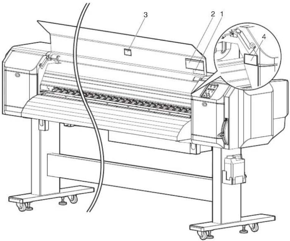
1.3.2 Location and type of warning labels
Pasting locations of the warning labels are shown in the following figure.
1.3.2.1 VJ-1638 Warning labels

text_image
Technical line drawing of a printing machine with numbered components and zoomed-in insets for detail views.| No. | Types of warning labels | |||
| 2 | ||||
| 3 | ||||
| 4 | ||||
| 5 | ||||
1.3.2.2 VJ-1638W Warning labels
text_image
Technical line drawing of a printing machine with numbered components and an inset close-up view| No. | Types of warning labels |
| 1 | |
| 2 |
注意
Caution
CAUTION 注意
◆ Do not give a direct wind from a fan or air conditioner to the machine.
※A wind may dry the ink in the head nozzles causing clogging that affects ink jetting, and you will not be able to obtain satisfactory printing results.
◆Normal cleaning should be done once a week if the printer is not used for a long period.
※If the printer is left without cleaning, the ink will be hardened inside the head nozzle, and may cause the head trouble.
◆ Do not open the front cover while printing.
Moreover. Do not touch the media while printing.
Good printing result might not be obtained.
Please remove the media and hold the lever up when not using for a long time. Due to the environment conditions, media float and wrinkle might happen that does not obtain the good result.
◆ Paper guides, platen and paper holding plate will become hot due to the heater temperature setting. Beware of being burned.
| No. | Types of warning labels |
| 3 | 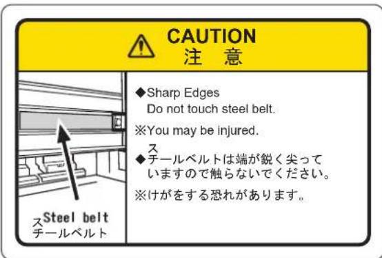 |
| 4 |  |
2 Product overview
This chapter explains the features of this printer along with the names and functions of each part.
2.1 Features
This section explains the main features of the printer.
(1) High-speed output
The new print head has realized high-speed output.
The printing width of 1,615mm has been made possible.
(2) Wide variety of compatible media
The height of Print head is adjustable to three levels, making it possible to print on various paper with the width of 0.08mm to 2.8mm.
(3) Vibrant color reproduction
4 colors of ink are used for printing in order to reproduce sharp and vivid colors.
High-capacity ink cartridges of 220ml and 440ml (VJ-1638 only) with dedicated IC chips are adopted.
High-capacity ink pack adapter to use 1000ml ink packs (option for VJ-1638 only) is available.
Ink consumption amount can be controlled by IC chips, greatly improving productivity. Use of variable dots can also improve color reproduction.
(4) Multi heaters adopted (for VJ-1638 only)
The media heating system developed by Lamiless series has been arranged for solvent ink.
Pre-heater, Platen heater, and After heater have been installed to improve ink settlement and drying speed of solvent ink on media.
(5) Effective use of media
A JOG feature is provided to allow setting of the print start position arbitrarily.
Printing can be performed on the media that has already been printed on, allowing effective use of margins.
(6) Optional Spectrophotometer available (for VJ-1638 only)
A compact and light Spectrophotometer (SPECTROVUE VM-10) is provided to measure visible light ranging from 400nm to 700nm (option). This can be used as a colorimeter for color calibration and profiling. (The conditions of use for color calibration and profiling depend on your RIP software.) Install Spectrophotometer on Print head to measure the color target automatically.
2.2 Names of parts and functions
This section explains the names and functions of each part.
2.2.1 Front section
NOTE
The illustrations used in this section are those of VJ-1638.

text_image
Technical diagram of a printer with numbered parts and zoomed-in insets for detail identification| No. | Name Function | |
| 1 | Media loading lever Used for fixing or releasing the media.Lower Lever to fix the media.Lower Lever further to fix the media firmly.Used to improve the accuracy of media feeding.Raise Lever to release the media. | |
| 2 | Operation panel | Used to set the operation condition, printer display and various functions.1音2.2.3 Operation panel |
| No. | Name | Function |
| 3 Front cover Used to prevent the user from coming in contact with the driving mechanism during the printer operation.Opened and closed when media is loaded or jammed.It is normally closed. | ||
| 4 Stand Used when installing the printer on a flat floor. | ||
| 5 Media guide Used to feed the media smoothly when loading or printing on the media.Heater (After heater) to dry ink is installed inside VJ-1638.VJ-1638W is not equipped with Heaters. | ||
| 6 Platen Installed inside of Front cover.Heater (Platen heater) to dry ink is installed inside VJ-1638.VJ-1638W is not equipped with Heaters. | ||
| 7 Pressurizing rollers Installed inside of Front cover.Press and hold the whole media when printing. | ||
| 8 Media cut groove Installed inside of Front cover.Used to cut media straight. | ||
| 9 Maintenance cover Used to prevent the user from touching the inner mechanical section.Open/close in the following cases.When cleaning Cleaning wiperWhen cleaning circumference of Print headWhen replacing CutterIt is normally closed. | ||
| 10 Adjuster Used to install the printer horizontally. | ||
| 11 Media holder plate Installed inside of Front cover.By attaching Media holder plates to both sides of the media, media warpage can be prevented to a degree. | ||
| 12 Connector | Used to install Spectrophotometer (SPECTROVUE VM-10) to VJ-1638.VJ-1638W is not equipped with Connector. | |
| 13 Waste fluid tank | Used for collecting waste ink discharged from the printer. | |
2.2.2 Rear section
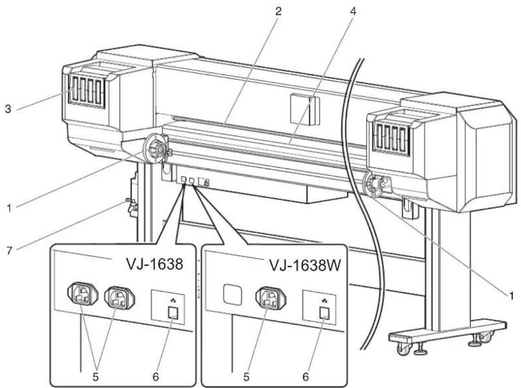
text_image
1 2 3 4 5 6 7 VJ-1638 VJ-1638W 5 6 5 6| No. | Name Function | |
| 1 | Roll media holder Load the roll media. | Equipped with Flanges to attach the roll media and Fixing levers to fix Roll media holders. |
| 2 | Media feed slot Used for feeding media. | |
| 3 | Ink cartridge slot Insert Ink cartridges. | |
| 4 | Media guide Used to feed the media smoothly when loading or printing on the media.Heater (Pre-heater) to dry ink is installed inside VJ-1638.VJ-1638W is not equipped with Heaters. | |
| 5 | AC inlet Used for connecting the power cord set. | |
| 6 | Network interface cable connector | Connects a network interface cable. |
| 7 | Waste fluid valve Open/close when discharging the waste fluid from Waste fluid tank.It is normally closed. |
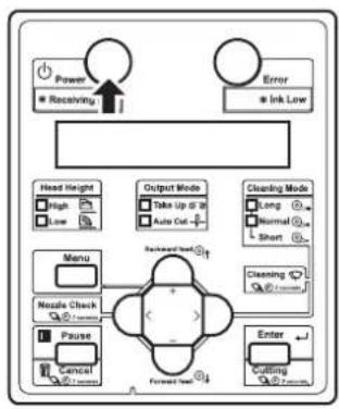
2.2.3 Operation panel
Used to set the operating conditions, to display the status of the printer, and to set various functions. Explains names of each operation key and status display along with the functions.
TIP
• Refer to the following for details regarding the operation method of Operation panel.
- When setting the menu from Operation panel: 4.3 Menu setups on Operation panel
- When performing various operations in Operation panel: 4.4 Operating from Operation panel
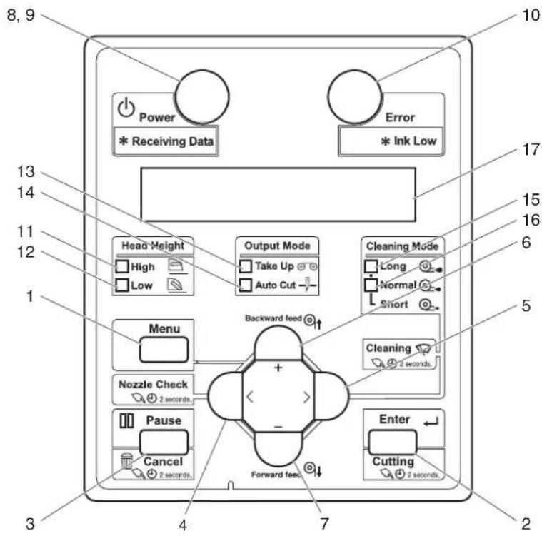
text_image
8, 9 Power * Receiving Data Error * Ink Low 13 14 11 12 1 Head Height High Low Output Mode Take Up Auto Cut Cleaning Mode Long Normal Short 5 Menu Nozzle Check 2 seconds Backward feed + - Pause Cancel 2 seconds Forward feed Enter Cutting 2 seconds 3 4 7 2(1) Operation keys
NOTE
- Operation keys are assigned with different functions and names depending on the printer status (Normal or Setup menu display).
For details about the printer status, refer to "2.3 Printer status outline".
| No. | Name Normal Setup | menu display | |
| 1 | [Menu] key | Shifts to the Setup menu. | Shifts from Setup menu display to Normal. |
| 2 [Enter] key | Restarts printing while printing is being suspended. | Select the menu to set, and shift to the next hierarchy.The setting is determined and saved. | |
| [Cutting] key Cuts the media when pressed for more than two seconds. | — | ||
| 3 [Pause] key Pauses printing. — | |||
| [Cancel] key • When printing:When pressed for more than two seconds, forcefully terminates printing and deletes one file of the remaining data.When receiving or analyzing data:When pressed for more than two seconds, deletes the data already received and analyzed. | Returns to the previous menu hierarchy.Changes made in the setting are discarded.Shifts from Setup menu display to Normal. | ||
| 4 [<] key — — | |||
| [Nozzle Check] key | Press and hold this key for two seconds or more to perform Nozzle Check printing. | — | |
| 5 [>] key • Sets Cleaning Mode.The lamp of Cleaning Mode that you set lights up in green. | Shifts the menu in the lower hierarchy. | ||
| [Cleaning] key | When pressed for more than two seconds, cleaning starts. | — | |
| 6 | [Backward↑] key | The media is fed in the reverse direction. | — |
| [+] key — | • Changes the displayed menu to the forward direction.The setting is changed to the reverse direction.The numeric value is increased during numerical input. | ||
| 7 | [Forward↓] key | Media is fed in the forward direction. | — |
| [-] key | — | • Changes the displayed menu to the reverse direction.Changes the setting in the forward direction.The numeric value is decreased during numerical input. | |
| 8 [Power] key Turns the printer ON/OFF.Turns the printer ON/OFF. | |||
(2) Display section
| No. | Name Color Status | Description | ||
| 9 | Power lamp Blue Lamp | ON | Power is ON. | |
| Lamp blinks | • Receiving and analyzing the data.• Performing media initial operation. | |||
| Lamp OFF | Power is OFF. | |||
| 10 | Error lamp Orange Lamp | ON | An error has occurred.The error content is displayed on the LCD. | |
| Lamp blinks | The remaining amount of ink is low. | |||
| Lamp OFF | There is no error. | |||
| 11 | High lamp Green Lamp | ON | The head height is set to High.When the Low lamp is also turned on, the head height is set to Mid. | |
| Lamp OFF | The head height is set to Low. | |||
| 12 | Low lamp | Green Lamp | ON | The head height is set to Low.When the High lamp is also turned on, the head height is set to Mid. |
| Lamp OFF | The head height is set to High. | |||
| 13 | Take Up lamp | Green Lamp | ON | Media ejection mode is set to "Take-up". |
| Lamp OFF | Media ejection mode is set to "Off" or "Auto cut". | |||
| 14 | Auto Cut lamp | Green Lamp | ON | Media ejection mode is set to "Auto cut". |
| Lamp OFF | Media ejection mode is set to "Off" or "Take-up". | |||
| 15 | Long lamp | Green Lamp | ON | • Cleaning mode is set to Long.• When the Normal lamp is also on, Cleaning mode is set to Short. |
| Lamp OFF | Cleaning Mode is set to Normal. | |||
| 16 | Normal lamp | Green Lamp | ON | • Cleaning Mode is set to Normal.• When the Long lamp is also on, Cleaning mode is set to Short. |
| Lamp OFF | Cleaning mode is set to Long. | |||
| 17 | LCD display section | — | — | Displays the operation status of the printer or an error message. |
TIP
- When an error requiring a restart (fatal malfunction for the printer operation) occurs, all lamps blink with an alarm.
7.2.3 Error requiring restart
If the error persists even when the malfunction is fixed, contact your local MUTOH dealer.
2.3 Printer status outline
This section explains the printer status.
2.3.1 Status
(1) Normal
Printing is possible when the media is loaded.
The various functions for printing can be performed on Operation panel.
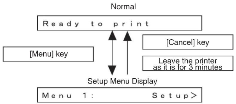
(2) Setup menu display
Various settings regarding printing can be made from Operation panel. The various functions for printing can be performed on Operation panel. Display contents in the LCD monitor of Operation panel are as follows.
(3) Panel display
flowchart
graph TD
    A["Ready to print"] --> B["Menu key"]
    A --> C["Setup Menu Display"]
    D["Cancel"] key --> A
    E["Leave the printer as it is for 3 minutes"] --> A
    F["Menu 1: Setup>"] --> A
2.3.2 Changing printer status
Follow the procedure below and change the printer status.
(1) Normal → Setup menu display
Press the [Menu] key on Operation panel when the printer is set to Normal.
- "Menu 1: Setup>" is displayed on Operation panel and the display shifts to the Setup menu.
NOTE
- For details regarding the Setup menu, refer to "4.3 Menu setups on Operation panel".
(2) Setup menu display → Normal
When the printer is at Setup menu display, perform either of the following operations to shift Operation panel to the Normal display.
- Press the [Cancel] or [Menu] key on Operation panel.
- In the Setup menu, leave the keys untouched for three minutes.
NOTE
- For details on Status message, refer to "7.2.1 Status messages".
3 Before using
This chapter explains necessary steps before using the printer.
3.1 Power cord set connection
This section explains power cord set connection.

WARNING
- Be sure to use the specified power cord set.
Using a power cord set other than the specified can cause an electric shock or fire. - Use the power cord set compliant with the safety standards, power-supply voltage, and plug shape of the country where the printer is used.
- Use a power cord set which is equipped with a protective earth, and securely connect it to the outlet.
- Do not use a damaged power cord set. It could lead to an electric shock or fire.

CAUTION
- Pay attention to the following points when handling the power cord set.
- Do not tamper with the power cord set.
- Do not put heavy objects on the power cord set.
- Do not bend, twist or pull the power cord set by force.
- Do not route the power cord set near heating appliances.
NOTE
- Contact your local MUTOH dealer if the power cord set is damaged.
Follow the procedure below to install the power cord set.
- Make sure that the printer is turned OFF.
flowchart
graph TD
    A["Power"] --> B["Receiving"]
    C["Error"] --> D["Ink Low"]
    E["Head Height"] --> F["High"]
    E --> G["Low"]
    H["Output Mode"] --> I["Take Up @ 18"]
    H --> J["Auto Out"]
    K["Cleaning Mode"] --> L["Long"]
    K --> M["Normal"]
    K --> N["Short"]
    O["Menu"] --> P["Nozzle Check"]
    O --> Q["Pause"]
    O --> R["Cancel"]
    S["Forward Test"] --> T["Enter"]
    U["Cutting"] --> V["Forward Test"]
    W["Cleaning"] --> X["Forward Test"]
NOTE
- The power is ON when the [Power] key of Operation panel is pressed in. Press the key once again to turn OFF the power.
- Connect the power cord set (VJ-1638: 2 pieces, VJ-1638W: 1 piece) to the AC inlet(s) (VJ-1638: 2 locations, VU01638W: 1 location) located on the right side of the printer.
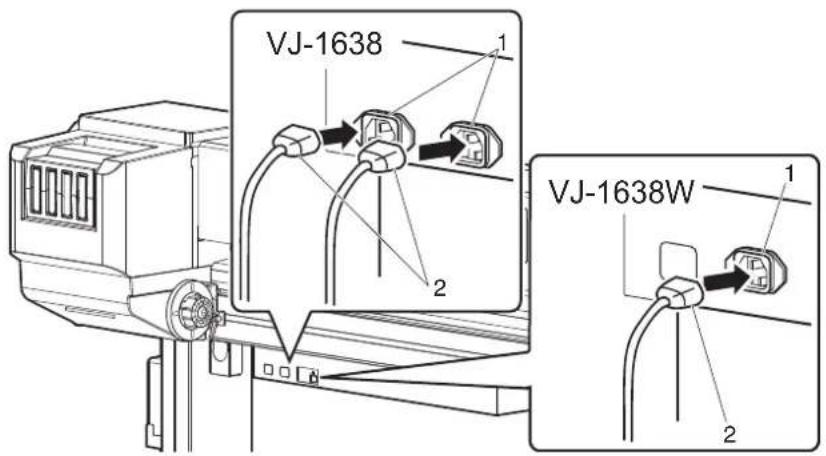
text_image
VJ-1638 1 2 VJ-1638W 1 2| No. | Name |
| 1 | A C i n l c t |
| 2 Power cord set | |
- Insert the plug of the power cord set firmly in the socket.
WARNING
- Do not pull out or insert the power plug with a wet hand. This could lead to an electric shock.
- Make sure to use only the specified power supply (AC 100 V to 120 V or AC 220 V to 240 V). If a power supply other than the specified voltage is used, it could cause an electric shock or fire.
- Take power for the printer directly from the power socket (AC 100 V - 120 V or AC 220 V - 240 V). Do not use multiple plugs on the same socket. This could generate heat and might cause a fire.
- Be sure to use a dedicated power socket with an earth wire for the power supply, and connect it to the earth wire. If the earth wire is not connected, it may cause an electric shock or fire.
-
Do not connect an earth wire to the following places.
-
Gas pipes
There is a possibility of ignition and explosion. - An earth wire of telephone cables and lightning rods
A heavy current might flow whenever lightning strikes.
• Water pipe and faucet The earth does not work if part of the metal pipe is plastic.
CAUTION
- Pay attention to the following points when handling the power plug. Any mishandling of the power cable could cause a fire.
- Make sure that no foreign substances such as dust are stuck to the power plug.
- Make sure that the power plug is inserted all the way.
- When you do not use the printer for a long period, make sure to pull out the power plug from the power socket for safety.
- Make sure to connect an earth wire to the earth connection that meets the following standards.
- An earth terminal of power socket
- An earth wire with a copper plate which is buried at 650 mm or more in the ground.
NOTE
- Contact your local MUTOH dealer if the earth connection is not/cannot be established.
- When the printer is ON, do not pull out the power cord set from the power socket. Whenever the plug is pulled out from the power socket, turn OFF the power on Operation panel and allow one minute or more before inserting the plug in the power socket again.
- When connecting two power cord sets, a total capacity of 19A is required. When you cannot ensure the capacity of 19A, connect two power cord sets to separate outlets.
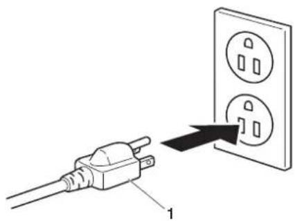
text_image
Diagram showing a plug connected to an electrical outlet with three socket symbols, labeled with number 1.| No. | Name |
| 1 | Power plug |
3.2 Turning the power ON/OFF
This section explains how to turn the printer ON/OFF.
3.2.1 Turning the power ON
Follow the procedure below to turn the power ON.
- Press the [Power] key on Operation panel to turn ON the printer.
- The Power lamp on Operation panel lights up in blue.
flowchart
graph TD
    A["Power"] --> B["* Receiving"]
    C["Error"] --> D["* Ink Low"]
    E["Head Height"] --> F["High"]
    E --> G["Low"]
    H["Output Mode"] --> I["Take Up @ 10"]
    H --> J["Auto Cut -"]
    K["Cleaning Mode"] --> L["Long"]
    K --> M["Normal"]
    K --> N["Short"]
    O["Menu"] --> P["Nzzle Check"]
    O --> Q["Pause"]
    O --> R["Cancel"]
    S["Backward feed"] --> T["+"]
    U["Forward feed"] --> V["-"]
    W["Enter"] --> X["Cutting"]
- The printer starts the initial operation.
- When the initial operation is complete, the printer enters Normal.
NOTE
- If there is a problem during the initial operation, a message is displayed on Operation panel and the printer may stop operating. If operation stops, refer to "7 Troubleshooting" and deal with the problem.
3.2.2 Turning the power OFF
Follow the procedure below to turn the printer OFF.
-
Verify the following regarding the operational condition of the printer.
-
Printing or other operations are not in progress.
• Operation panel display is Normal. - The Low lamp on Operation panel lights up in green.
• The High lamp on Operation panel is turned off.
NOTE
- If the High lamp on Operation panel lights up in green, the head height is set to High or Mid. Return the head height to Low before turning the power OFF. 4.2.5.3 When setting the head height to Low
- Press the [Power] key on Operation panel to turn OFF the printer.
- The Power lamp on Operation panel is turned off.
NOTE
- If Operation panel is in the following status, the power is ON.
• The [Power] key is pressed in.
• The Power lamp lights up in blue.
Press the key once again to turn OFF the power.
flowchart
graph TD
    A["Power"] --> B["Receiving"]
    C["Error"] --> D["Ink Low"]
    E["Head Height"] --> F["High"]
    E --> G["Low"]
    H["Output Mode"] --> I["Take Up if 10"]
    H --> J["Auto Cut"]
    K["Cleaning Mode"] --> L["Long"]
    K --> M["Normal"]
    K --> N["Short"]
    O["Menu"] --> P["Nestle Check"]
    O --> Q["Pause"]
    O --> R["Cancel"]
    S["Forward Line"] --> T["Enter"]
    U["Cutting"] --> V["Reset"]
    W["Order"] --> X["Order"]
• The printer turns the power OFF.
- "Power Off" is displayed on Operation panel.
NOTE
- If the head height is set to High or Mid, "Set Height to Low" is displayed on Operation panel, and the printer stops the procedure to turn the power OFF.
To restart the procedure, return the head height to Low.
4.2.5.3 When setting the head height to Low
- All the lamps on Operation panel and the LCD monitor are turned OFF.
• The printer automatically turns the power OFF.
NOTE
- If there is a problem during turning OFF operation, a message is displayed on Operation panel and the printer may stop operating.
If operation stops, refer to "7 Troubleshooting" and deal with the problem.
- After turning OFF the printer, wait for ten seconds or longer to turn it ON again.
- Raise the media loading lever when the printer is not used for a long time.

natural_image
Technical line drawing of a mechanical device with no visible text or symbols| No. | Name |
| 1 | Media loading lever |
3.3 Filling ink
This section describes the procedure to install Ink cartridges for the first time.

CAUTION
- Before operation, make sure to read the Material Safety Data Sheet (MSDS).
- When handling Ink cartridges or Ink packs, pay attention so that ink does not come into contact with your eyes or skin. If ink gets into your eyes or sticks to your skin, immediately wash it off with water. Failing to do so might cause irritation or light inflammation of eyes. In case of any abnormality, consult a physician immediately.
- Do not disassemble Ink cartridges or Ink packs. If disassembled, ink might come into contact with your eyes or skin.
- Comply strictly with the following during ink filling.
- Do not turn OFF the printer.
- Do not unplug the power cord set.
- Do not open Front cover.
- Do not open Maintenance cover.
- Do not raise Media loading lever.
NOTE
- Do not use the Ink cartridge(s) you have inserted into Ink cartridge slot(s) for other printers. The Ink cartridge(s) will not be used again.
-
Use genuine Ink cartridges or Ink packs for charging. This printer is designed to use genuine Ink cartridges and Ink packs. If you use Ink cartridges which are not produced by the original manufacturer,
-
printing might become blurred and the end of the ink might not be detected correctly.
- Any problems caused by using an ink bag other than those recommended above will not be covered by the warranty, and repair expenses will be paid by the customer.
- For types and details of Ink cartridges, contact your local MUTOH dealer.
- Do not give Ink cartridges or Ink packs strong shakes. Doing so may cause ink leakage.
- Do not disassemble Ink cartridges. A disassembled Ink cartridge or Ink packs cannot be used.
- Be sure to use the dedicated cleaning fluid.
• (VJ-1638)product number: VJ-MSINK3-CL220, VJ-MSINK3-CL1000
• (VJ-1638W)product number: RJ-FGCLS
- Shake the Ink cartridges or Ink packs lightly before installing. Doing so may affect the print quality.
- When the Ink cartridge or Ink pack is moved from a cold place to a warm place, leave it for 3 hours or more in the new printing environment before printing.
- Do not insert/remove Ink cartridges and High-capacity ink pack adapter more than then number of times shown below. Ink cartridges: 10 times
High-capacity ink pack adapter: 6 times
If Ink cartridge has been removed/inserted more than the number of times shown above, it cannot be used even when there is remaining ink. High-capacity ink pack adapter requires replacement of Connector rubber.
- Ink cartridges and Ink packs for this printer have dedicated IC chips on them. If removing/inserting the ink cartridges and High-capacity ink pack adapter (option) in the following situations, the information within the IC chips may be damaged and the cartridges cannot be used.
- During printing
- For ten seconds after inserting all Ink cartridges
3.3.1 When using 220ml Ink cartridges
Follow the procedure below to install the 220ml Ink cartridges.
NOTE
The procedures differ between VJ-1638 and VJ-1638W. Check your printer model name and follow the correct procedure.
TIP
- The 220ml cartridges can be inserted horizontally or vertically.
This section describes the case of horizontal insertion angle only. Refer to "3.3.2 When using 440ml Ink cartridges (VJ-1638 only)" for the case of vertical insertion.
3.3.2 When using 440ml Ink cartridges (VJ-1638 only)
3.3.1.1 For VJ-1638
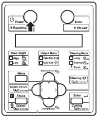
- Turn the printer ON.
flowchart
graph TD
    A["Power"] --> B["Receiving"]
    C["Error"] --> D["Ink Law"]
    E["Head Height"] --> F["High"]
    E --> G["Low"]
    H["Output Mode"] --> I["Take Up @ 10"]
    H --> J["Auto Cut +"]
    K["Cleaning Mode"] --> L["Long"]
    K --> M["Normal"]
    K --> N["Short"]
    O["Menu"] --> P["Nozzle Check"]
    O --> Q["Pause"]
    O --> R["Cancel"]
    O --> S["Forward End"]
    T["Enter"] --> U["Cutting"]
    T --> V["Firearm"]
• The printer starts the initializing operation.
• After the initial operation is compete, "Start Ink Charge -> E" is displayed on Operation panel.
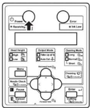
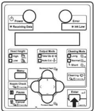
- Press the [Enter] key on Operation panel.

flowchart
graph TD
    A["Power"] --> B["Receiving Data"]
    C["Error"] --> D["Ink Low"]
    E["Menu"] --> F["Nezzle Check"]
    G["Pause"] --> H["Cancel"]
    I["Forward test"] --> J["Enter"]
    K["Head Height"] --> L["High"]
    K --> M["Low"]
    N["Output Mode"] --> O["Take Up @ 10"]
    N --> P["Auto Cut"]
    Q["Cleaning Mode"] --> R["Long"]
    Q --> S["Normal"]
    Q --> T["Short"]
    U["Cleaning Mode"] --> V["Short"]
    W["Enter"] --> X["Forward test"]
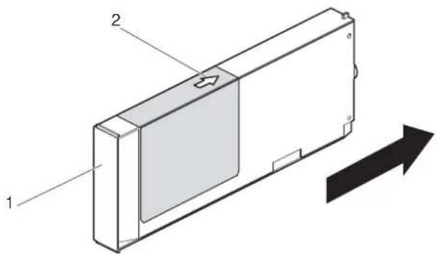
- "Insert CleaningCart." is displayed on Operation panel.
-
Take out Cleaning cartridges (8 pieces) from the bags.
-
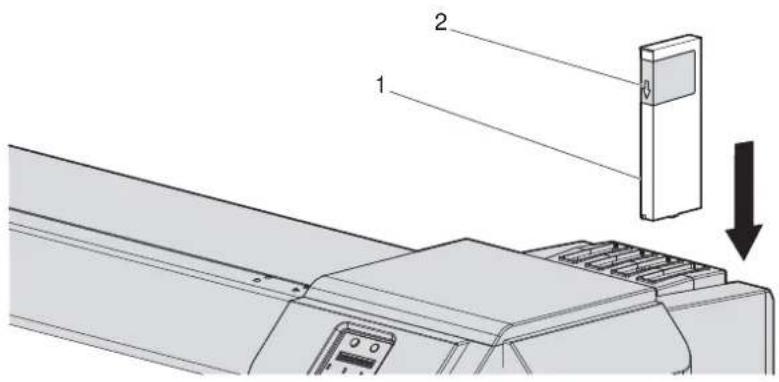
Insert Cleaning cartridge into Ink cartridge slot.
- Keep the arrow of Cleaning cartridge facing up and insert it into the printer.

text_image
Technical diagram of a device with labeled components and directional arrow indicating movement or force| No. | Name |
| 1 | Cleaning cartridge |
| 2 | A r r o w |
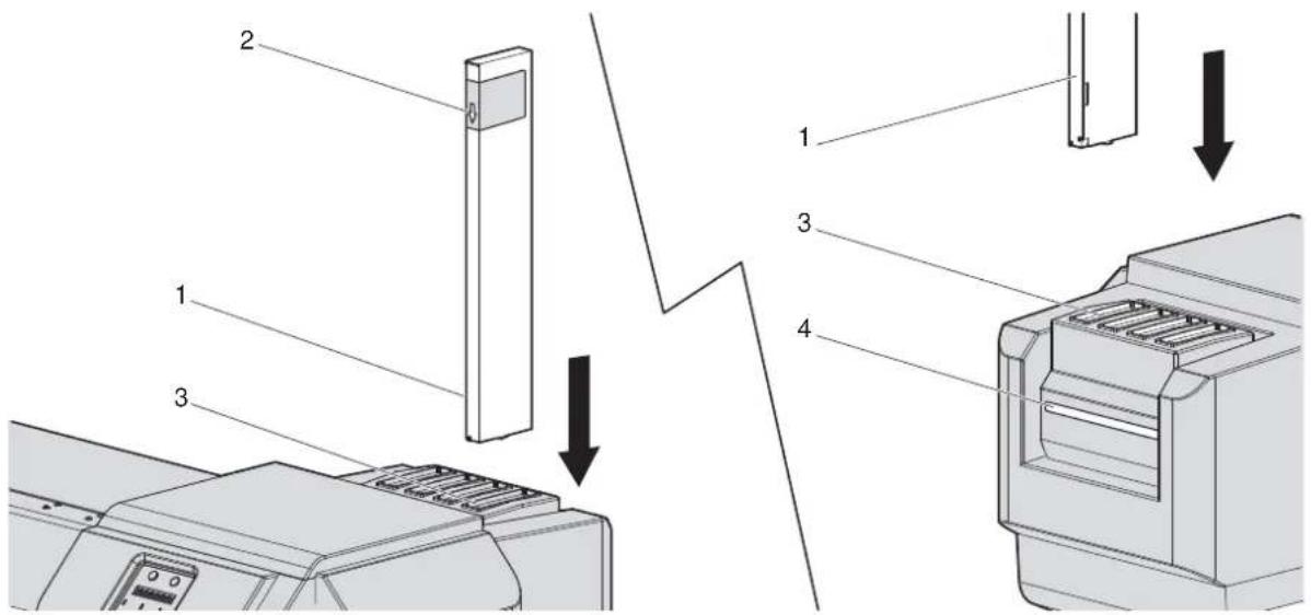
- Insert Cleaning cartridge all the way in Ink cartridge slot.

text_image
Technical diagram showing two views of a mechanical device with labeled components and directional arrows indicating flow or movement.| No. | Name |
| 1 | Cleaning cartridge |
| 2 | Ink cartridge slots |
- If the head height is set to High, "Change Head Gap Low" is displayed on Operation panel. Change the head height to Low.
4.2.5 Head height adjustment
- When all Cleaning cartridges are installed, "Busy-Washing" is displayed on Operation panel, and the printer starts charging the cleaning fluid.
- When Celaning fluid has been charged, "Remove Cartridges" is displayed on Operation panel.
- Remove all Cleaning cartridges.
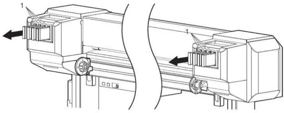
natural_image
Technical line drawing of a mechanical assembly with two views (top and side), no visible text or symbols| No. | Name |
| 1 | Cleaning cartridge |
- "Busy-Washing" is displayed on Operation panel and the printer starts head cleaning.
-
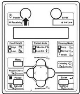
When head cleaning is complete, "Wash retry? No" is displayed on Operation panel.
-
Press the [Enter] key on Operation panel.
flowchart
graph TD
    A["Power"] --> B["Receiving Data"]
    C["Error"] --> D["Ink Low"]
    E["Head Height"] --> F["High"]
    E --> G["Low"]
    H["Output Mode"] --> I["Take Up @ 10"]
    H --> J["Auto Cut"]
    K["Cleaning Mode"] --> L["Long"]
    K --> M["Normal"]
    K --> N["Short"]
    O["Menu"] --> P["Nzzle Check"]
    O --> Q["Pause"]
    O --> R["Cancel"]
    S["Enter"] --> T["Forward Test"]
    U["Recreer Test"] --> V["+"]
    W["+"] --> X["-"]
- "Insert InkCartridges" is displayed on Operation panel.
-
Install Ink cartridges (K, C, M, Y: 2 each) in Ink cartridge slots (K, C, M, Y: 2 each) on the back of the printer.
-
Shake Ink cartridges 2 to 3 times lightly before installing them into Ink cartridge slots.
- Make sure that Ink cartridges are inserted into the correct Slots.
Match the ink color label with the ink color before inserting Ink pack.
- Keep the arrow of Ink cartridge facing up and insert it into the printer.
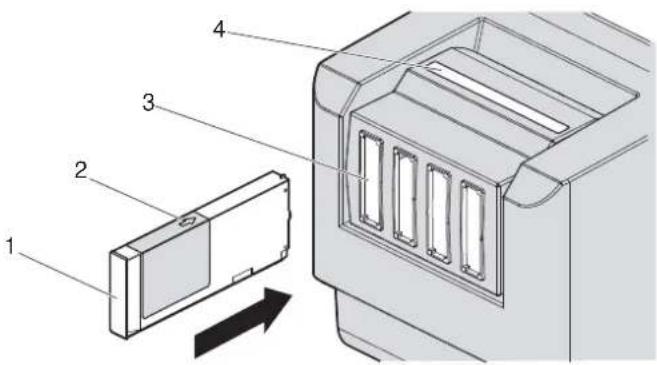
text_image
Technical diagram showing labeled components of a device or enclosure, including a rectangular component and a lid with four slots.| No. | Name |
| 1 | Ink cartridge |
| 2 | A r r o w |
| 3 | Ink cartridge slots |
| 4 | Ink color labels |
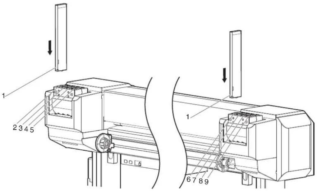
- Insert Ink cartridges all the way in Ink cartridge slots.

text_image
1 2 3 4 5 1 6 7 8 9| No. | Name |
| 1 | Ink cartridge |
| 2 | Ink cartridge slot K1 |
| 3 | Ink cartridge slot K2 |
| 4 | Ink cartridge slot C1 |
| 5 | Ink cartridge slot C2 |
| 6 | Ink cartridge slot M1 |
| 7 | Ink cartridge slot M2 |
| 8 | Ink cartridge slot Y1 |
| 9 | Ink cartridge slot Y2 |
- When an Ink cartridge is installed, "Ink Refill **%" is displayed on Operation panel and ink replenishment starts.
- Initial filling takes about 17 minutes. Ink filling operation and pause operation are repeated during the initial ink replenishment.
- When "100%" is displayed, the initial ink replenishment is complete.
• After the initial ink replenishment is complete, "Media End" is displayed on Operation panel.
CAUTION
- Comply strictly with the following during ink filling. If filling is interrupted, ink will be lost when filling is resumed.
- Do not turn OFF the power of the printer.
- Do not unplug the power cord set of the printer.
- Do not open Front cover.
- Do not open Maintenance cover.
- Do not raise Media loading lever.
NOTE
- If the printer perform the nozzle check printing immediately after the initial ink replenishment is complete, the following results may occur.
- Printed lines become blurred.
• The data is partially not printed.
In such cases, follow "5.3 Cleaning menu" and refill a small amount of ink. Then, check the printing result.
If there is no improvement in the print result even after refilling a small amount of ink, leave the printer unused for an hour or more. Then, refill a small amount of ink again and check the print result.
If there is still no improvement, contact your local MUTOH dealer.
3.3.1.2 For VJ-1638W
- Turn the printer ON.

flowchart
graph TD
    A["Power"] --> B["Receiving"]
    C["Error"] --> D["Ist Low"]
    E["Menu"] --> F["Nozzle Check"]
    F --> G["Pause"]
    G --> H["Control"]
    I["Output Mode"] --> J["Take Up @ 10"]
    J --> K["Auto Cut -"]
    L["Bayward feel"] --> M["+"]
    N["Cleaning Mode"] --> O["Long"]
    O --> P["Normal"]
    P --> Q["Short"]
    R["Enter"] --> S["Cutting"]
    S --> T["Control"]
• The printer starts the initializing operation.
• After the initial operation is compete, "Start Ink Charge -> E" is displayed on Operation panel
- Press the [Enter] key on Operation panel.
flowchart
graph TD
    A["Power"] --> B["Receiving Data"]
    C["Error"] --> D["Ink Low"]
    E["Head Height"] --> F["High"]
    E --> G["Low"]
    H["Output Mode"] --> I["Data Up to 28"]
    H --> J["Auto Cut"]
    K["Cleaning Mode"] --> L["Long"]
    K --> M["Normal"]
    K --> N["Short"]
    O["Menu"] --> P["Nozzle Check"]
    O --> Q["Pause"]
    O --> R["Cancel"]
    S["Forward Test"] --> T["Enter"]
    U["Forward Test"] --> V["Enter"]
- When head cleaning is complete, "Wash retry? No" is displayed on Operation panel.
- Select whether to perform cleaning of the ink path before the initial ink charge.
NOTE
- Cleaning may be required depending on the ink type to be set.
• To perform head cleaning, make sure to use the cleaning liquid that matches the ink.
a. When cleaning is required, press the [+] key or [-] key to select "Yes".

flowchart
graph TD
    A["Power"] --> B["Receiving Data"]
    C["Error"] --> D["Ink Low"]
    E["Head Height"] --> F["High"]
    E --> G["Low"]
    H["Output Mode"] --> I["Take Up if 3"]
    H --> J["Auto Cut"]
    K["Cleaning Mode"] --> L["Long"]
    K --> M["Normal"]
    K --> N["Short"]
    O["Menu"] --> P["Nostal Check"]
    O --> Q["Pause"]
    O --> R["Cancel"]
    S["Enter"] --> T["Cutting"]
    U["Feedback"] --> V["+"]
    W["Feedback"] --> X["-"]
    Y["Feedback"] --> Z["-"]
    style A fill:#f9f,stroke:#333
    style C fill:#f9f,stroke:#333
    style E fill:#f9f,stroke:#333
    style K fill:#f9f,stroke:#333
    style O fill:#f9f,stroke:#333
    style U fill:#f9f,stroke:#333
    style S fill:#f9f,stroke:#333
    style V fill:#f9f,stroke:#333
b. When cleaning is not required, proceed to the step 8.
- Press the [Enter] key on Operation panel.

flowchart
graph TD
    A["Power"] --> B["* Receiving Data"]
    C["Error"] --> D["* Ink Low"]
    E["Manual Check"] --> F["Menu"]
    G["Pause"] --> H["Manual Check"]
    I["Forward Load"] --> J["Enter"]
    K["Manual Check"] --> L["Manual Check"]
    M["Manual Check"] --> N["Manual Check"]
    O["Manual Check"] --> P["Manual Check"]
    Q["Manual Check"] --> R["Manual Check"]
    S["Manual Check"] --> T["Manual Check"]
    U["Manual Check"] --> V["Manual Check"]
    W["Manual Check"] --> X["Manual Check"]
    Y["Manual Check"] --> Z["Manual Check"]
    AA["Manual Check"] --> AB["Manual Check"]
    AC["Manual Check"] --> AD["Manual Check"]
    AE["Manual Check"] --> AF["Manual Check"]
    AG["Manual Check"] --> AH["Manual Check"]
    AI["Manual Check"] --> AJ["Manual Check"]
    AK["Manual Check"] --> AL["Manual Check"]
    AM["Manual Check"] --> AN["Manual Check"]
    AO["Manual Check"] --> AP["Manual Check"]
    AQ["Manual Check"] --> AR["Manual Check"]
    AS["Manual Check"] --> AT["Manual Check"]
    AU["Manual Check"] --> AV["Manual Check"]
    AW["Manual Check"] --> AX["Manual Check"]
    AY["Head Height"] --> AZ["High"]
    AY --> BA["Low"]
    BB["Output Mode"] --> BC["Take Up @ 10"]
    BB --> BD["Auto Cut -"]
    BC --> BE
    BD --> BF
    BG["Cleaning Mode"] --> BH["Long"]
    BG --> BI["Normal"]
    BG --> BJ["Short"]
    BK["Cleaning"] --> BL["Short"]
    BM["Enter"] --> BN["Farmbox"]
- "Insert CleaningCart." is displayed on Operation panel.
-
Take out Cleaning cartridges (8 pieces) from the bags.
-
Insert Cleaning cartridge into Ink cartridge slot.
- Keep the arrow of Cleaning cartridge facing up and insert it into the printer.
text_image
Technical diagram of a device with labeled components and directional arrow indicating movement or flow| No. | Name |
| 1 | Cleaning cartridge |
| 2 | Arrow |
- Insert Cleaning cartridge all the way in Ink cartridge slot.
text_image
Technical diagram showing two views of a mechanical device with labeled components and directional arrows indicating assembly or movement.| No. | Name |
| 1 | Cleaning cartridge |
| 2 | Ink cartridge slots |
- If the head height is set to High, "Change Head Gap Low" is displayed on Operation panel. Change the head height to Low.
4.2.5 Head height adjustment
- When all Cleaning cartridges are installed, "Busy-Washing" is displayed on Operation panel, and the printer starts charging the cleaning fluid.
- When Celaning fluid has been charged, "Remove Cartridges" is displayed on Operation panel.
- Remove all Cleaning cartridges.

natural_image
Technical line drawing of a mechanical assembly with two views (top and side), no visible text or symbols| No. | Name |
| 1 | Cleaning cartridge |
- "Busy-Washing" is displayed on Operation panel and the printer starts head cleaning.
-
When head cleaning is complete, "Wash retry? No" is displayed on Oeration panel.
-
Press the [Enter] key on Operation panel.
flowchart
graph TD
    A["Power"] --> B["Receiving Data"]
    C["Error"] --> D["Ink Low"]
    E["Head Height"] --> F["High"]
    E --> G["Low"]
    H["Output Mode"] --> I["Take Up @ 20"]
    H --> J["Auto Cut"]
    K["Cleaning Mode"] --> L["Long"]
    K --> M["Normal"]
    K --> N["Short"]
    O["Menu"] --> P["Nzzle Check"]
    O --> Q["Pause"]
    O --> R["Cancel"]
    S["Forward load"] --> T["Enter"]
    U["Backward load"] --> V["+"]
    W["Forward load"] --> X["-"]
- "Insert InkCartridges" is displayed on Operation panel.
-
Install Ink cartridges (K, C, M, Y: 2 each) in Ink cartridge slots (K, C, M, Y: 2 each) on the back of the printer.
-
Shake Ink cartridges 2 to 3 times lightly before installing them into Ink cartridge slots.
- Make sure that Ink cartridges are inserted into the correct Slots.
Match the ink color label with the ink color before inserting Ink pack. - Keep the arrow of Ink cartridge facing up and insert it into the printer.
text_image
Technical diagram showing a device component with numbered parts and an arrow indicating direction or movement.| No. | Name |
| 1 | Ink cartridge |
| 2 | Arrow |
| 3 | Ink cartridge slots |
| 4 | Ink color labels |
- Insert Ink cartridges all the way in Ink cartridge slots.

text_image
1 2 3 4 5 1 6 7 8 9| No. | Name |
| 1 | Ink cartridge |
| 2 | Ink cartridge slot K1 |
| 3 | Ink cartridge slot K2 |
| 4 | Ink cartridge slot C1 |
| 5 | Ink cartridge slot C2 |
| 6 | Ink cartridge slot M1 |
| 7 | Ink cartridge slot M2 |
| 8 | Ink cartridge slot Y1 |
| 9 | Ink cartridge slot Y2 |
- When an Ink cartridge is installed, "Ink Refill **%" is displayed on Operation panel and ink replenishment starts.
- Initial filling takes about 17 minutes.
Ink filling operation and pause operation are repeated during the initial ink replenishment.
- When "100%" is displayed, the initial ink replenishment is complete.
• After the initial ink replenishment is complete, "Media End" is displayed on Operation panel.
CAUTION
- Comply strictly with the following during ink filling. If filling is interrupted, ink will be lost when filling is resumed.
- Do not turn OFF the power of the printer.
- Do not unplug the power cord set of the printer.
- Do not open Front cover.
- Do not open Maintenance cover.
- Do not raise Media loading lever.
NOTE
- If the printer perform the nozzle check printing immediately after the initial ink replenishment is complete, the following results may occur.
- Printed lines become blurred.
• The data is partially not printed.
In such cases, follow "5.3 Cleaning menu" and refill a small amount of ink. Then, check the printing result.
If there is no improvement in the print result even after refilling a small amount of ink, leave the printer unused for an hour or more. Then, refill a small amount of ink again and check the print result.
If there is still no improvement, contact your local MUTOH dealer.
3.3.2 When using 440ml Ink cartridges (VJ-1638 only)
NOTE
440ml Ink cartridges are not compatible with VJ-1638W.
Follow the procedure below to install Ink cartridges.
- Check the angle of Ink cartridge slot to see if the insertion angle of Ink cartridge is vertical.

natural_image
Technical line drawing of a mechanical device with two views (labeled 1), showing internal components and mounting points (no text or symbols present)| No. | Name |
| 1 | Ink cartridge slot |
- If the insertion angle of Ink cartridge is not vertical, change the angle.
3.3.3 Changing the angle of Ink cartridge slot
NOTE
Make sure that the insertion angle of the 440ml cartridge is vertical. If the cartridge is inserted obliquely, the cartridge may fall over.
- Turn the printer ON.
flowchart
graph TD
    A["Power"] --> B["Receiving"]
    C["Error"] --> D["Ink Low"]
    E["Head Height"] --> F["High"]
    E --> G["Low"]
    H["Menu"] --> I["Nutle Check"]
    H --> J["Pause"]
    H --> K["Control"]
    L["Output Mode"] --> M["Take Up @ 10"]
    L --> N["Auto Cut -"]
    O["Cleaning Mode"] --> P["Long"]
    O --> Q["Normal"]
    O --> R["Short"]
    S["Backward Start"] --> T["+"]
    U["Forward Start"] --> V["-"]
    W["Enter"] --> X["Cutting"]
    Y["Control"] --> Z["Control"]
• The printer starts the initializing operation.
• After the initial operation is compete, "Start Ink Charge -> E" is displayed on Operation panel.
- Press the [Enter] key on Operation panel.

flowchart
graph TD
    A["Power"] --> B["* Receiving Data"]
    C["Error"] --> D["* Ink Low"]
    E["Head Height"] --> F["High"]
    E --> G["Low"]
    H["Output Mode"] --> I["Take Up @ 10"]
    H --> J["Auto Cut -"]
    K["Cleaning Mode"] --> L["Jump"]
    K --> M["Normal"]
    K --> N["Short"]
    O["Menu"] --> P["Nozzle Check"]
    O --> Q["Pause"]
    O --> R["Cancel"]
    S["Forward Test"] --> T["Enter"]
    U["Forward Test"] --> V["Enter"]
- "Insert CleaningCart." is displayed on Operation panel.
-
Take out Cleaning cartridges (8 pieces) from the bags.
-
Insert Cleaning cartridge into Ink cartridge slot.
- Keep the arrow of Cleaning cartridge facing the front side of the printer and insert it into the printer.
text_image
Technical diagram showing a mechanical assembly with labeled components and directional arrow indicating motion or force.| No. | Name |
| 1 | Cleaning cartridge |
| 2 | Arrow |
- Insert Cleaning cartridge all the way in Ink cartridge slot.

text_image
Technical diagram showing two views of a mechanical device with labeled components and directional arrows indicating assembly or inspection.| No. | Name |
| 1 | Cleaning cartridge |
| 2 | Ink cartridge slots |
- If the head height is set to High, "Change Head Gap Low" is displayed on Operation panel. Change the head height to Low.
4.2.5 Head height adjustment
- When all Cleaning cartridges are installed, "Busy-Washing" is displayed on Operation panel, and the printer starts charging the cleaning fluid.
- When Celaning fluid has been charged, "Remove Cartridges" is displayed on Operation panel.
6. Remove all Cleaning cartridges.

natural_image
Technical line drawing of two mechanical assembly components with directional arrows indicating motion or force (no text or symbols present)| No. | Name |
| 1 | Cleaning cartridge |
- "Busy-Washing" is displayed on Operation panel and the printer starts head cleaning.
-
When head cleaning is complete, "Wash retry? No" is displayed on Oeration panel.
-
Press the [Enter] key on Operation panel.
flowchart
graph TD
    A["Power"] --> B["* Receiving Data"]
    C["Error"] --> D["* Ink Low"]
    E["Head Height"] --> F["High"]
    E --> G["Low"]
    H["Output Mode"] --> I["Take Up @ 0"]
    H --> J["Auto Cut -1"]
    K["Cleaning Mode"] --> L["Long"]
    K --> M["Normal"]
    K --> N["Short"]
    O["Menu"] --> P["Nzzle Check"]
    O --> Q["Puzzle"]
    O --> R["Cancel"]
    S["Backward Head"] --> T["Forward Head"]
    U["Enter"] --> V["Forward Head"]
    W["Control"] --> X["Control"]
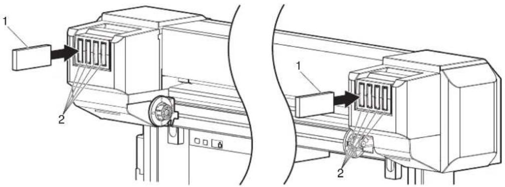
- "Insert InkCartridges" is displayed on Operation panel.
-
Install Ink cartridges (K, C, M, Y: 2 each) in Ink cartridge slots (K, C, M, Y: 2 each) on the back of the printer.
-
Shake Ink cartridges 2 to 3 times lightly before installing them into Ink cartridge slots.
- Make sure that Ink cartridges are inserted into the correct Slots.
Match the ink color label with the ink color before inserting Ink pack. - Keep the arrow of Cleaning cartridge facing the front side of the printer and insert it.
text_image
Diagram showing labeled components of a printer or printer assembly, including parts 1, 2, 3, and 4 with directional arrows indicating assembly steps.| No. | Name |
| 1 | Ink cartridge |
| 2 | Arrow |
| 3 | Ink cartridge slots |
| 4 | Ink color labels |
- Insert Ink cartridges all the way in Ink cartridge slots.
text_image
1 2 3 4 5 1 6 7 8 9| No. | Name |
| 1 | Ink cartridge |
| 2 | Ink cartridge slot K1 |
| 3 | Ink cartridge slot K2 |
| 4 | Ink cartridge slot C1 |
| 5 | Ink cartridge slot C2 |
| 6 | Ink cartridge slot M1 |
| 7 | Ink cartridge slot M2 |
| 8 | Ink cartridge slot Y1 |
| 9 | Ink cartridge slot Y2 |
- When an Ink cartridge is installed, "Ink Refill **%" is displayed on Operation panel and ink replenishment starts.
- Initial filling takes about 17 minutes. Ink filling operation and pause operation are repeated during the initial ink replenishment.
- When "100%" is displayed, the initial ink replenishment is complete.
• After the initial ink replenishment is complete, "Media End" is displayed on Operation panel.

CAUTION
- Comply strictly with the following during ink filling. If filling is interrupted, ink will be lost when filling is resumed.
- Do not turn OFF the power of the printer.
- Do not unplug the power cord set of the printer.
- Do not open Front cover.
- Do not open Maintenance cover.
- Do not raise Media loading lever.
NOTE
- If the printer perform the nozzle check printing immediately after the initial ink replenishment is complete, the following results may occur.
- Printed lines become blurred.
• The data is partially not printed.
In such cases, follow "5.3 Cleaning menu" and refill a small amount of ink. Then, check the printing result.
If there is no improvement in the print result even after refilling a small amount of ink, leave the printer unused for an hour or more. Then, refill a small amount of ink again and check the print result.
If there is still no improvement, contact your local MUTOH dealer.
3.3.3 Changing the angle of Ink cartridge slot
The angle of the ink cartridge slot of this printer varies depending on the capacity of ink cartridges (or ink packs).
Follow the procedure below to change the angle.
3.3.3.1 When inserting Ink cartridges vertically
Before installing the 440ml cartridges, change the angle as follows.
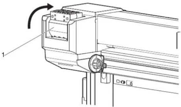
- Rotale Ink cartridge slot by 90 degrees upward.
natural_image
Technical line drawing of a mechanical assembly with no visible text or symbols| No. | Name |
| 1 | Ink cartridge slot |
- Check if Ink cartridge slot is vertical.
- Check the opposite side in the same way.
3.3.3.2 When inserting Ink cartridges horizontally
Before installing High-capacity ink pack adapters, change the angle as follows.
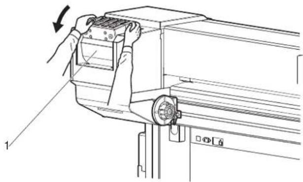
- Tilt Ink cartridge slot slightly toward the rear side of the printer.
natural_image
Line drawing of a mechanical device with hands operating it, showing a press or lever mechanism (no text or symbols present)| No. | Name |
| 1 | Ink cartridge slot |
- To unlock, return Ink cartridge slot to the original position.

natural_image
Technical line drawing of a mechanical assembly with a hand operating a component (no text or symbols present)| No. | Name |
| 1 | Ink cartridge slot |
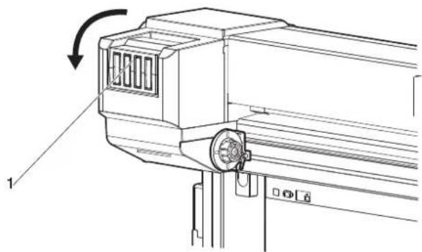
- Rotale Ink cartridge slot by 90 degrees downward.
natural_image
Technical line drawing of a mechanical device with an arrow indicating rotational motion (no text or symbols present)| No. | Name |
| 1 | Ink cartridge slot |
- Check if Ink cartridge slot is horizontal.
- Check the opposite side in the same way.
3.3.4 Installing High Capacity Ink Pack Adapter (option) for VJ-1638 only
Use the optional High-capacity ink pack adapter to use the 1000ml Ink packs on VJ-1638.

High-capacity ink pack adapters are not compatible with VJ-1638W.
Follow the procedure below to install High-capacity ink pack adapter.
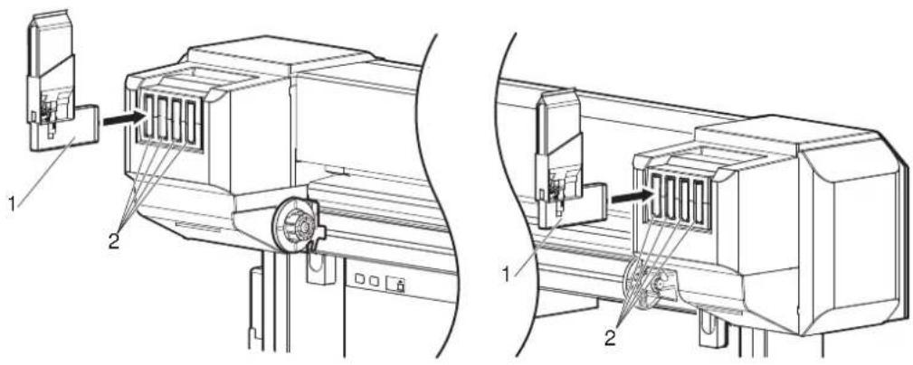
- Check the angle of Ink cartridge slot to see if the insertion angle of Ink cartridge is horizontal.

natural_image
Technical line drawing of two mechanical components with labeled parts (no text or symbols present)| No. | Name |
| 1 | Ink cartridge slot |
- If the insertion angle of Ink cartridge is not horizontal, change the angle.
3.3.3 Changing the angle of Ink cartridge slot
- Turn the printer ON.

flowchart
graph TD
    A["Power"] --> B["* Receiving"]
    C["Error"] --> D["@ Ink Low"]
    E["Head Height"] --> F["High"]
    E --> G["Low"]
    H["Menu"] --> I["Nzzle Check"]
    H --> J["Pause"]
    H --> K["Cancel"]
    L["Output Mode"] --> M["Take Up @ 10"]
    L --> N["Auto Cut"]
    O["Cleaning Mode"] --> P["Long"]
    O --> Q["Normal"]
    O --> R["Short"]
    S["Forward Load"] --> T["+"]
    U["Enter"] --> V["Cutting"]
    W["Backward Load"] --> X["+"]
    Y["Forward Load"] --> Z["-"]
• The printer starts the initializing operation.
• After the initial operation is compete, "Start Ink Charge -> E" is displayed on Operation panel.
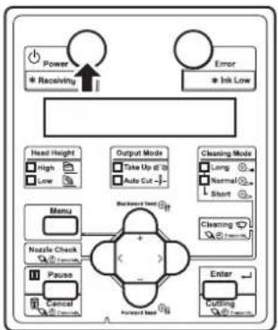
- Press the [Enter] key on Operation panel.

flowchart
graph TD
    A["Power"] --> B["Receiving Data"]
    C["Error"] --> D["Ink Low"]
    E["Head Height"] --> F["High"]
    E --> G["Low"]
    H["Output Mode"] --> I["Data Up to 28"]
    H --> J["Auto Cut"]
    K["Cleaning Mode"] --> L["Long"]
    K --> M["Normal"]
    K --> N["Short"]
    O["Menu"] --> P["Nzzle Check"]
    O --> Q["Pause"]
    O --> R["Cancel"]
    S["Forward Test"] --> T["Enter"]
    U["Forward Test"] --> V["Enter"]
- "Insert CleaningCart." is displayed on Operation panel.
-
Take out Cleaning fluid pack from the bag.
-
Install Cleaning fluid pack and IC chip card to High-capacity ink pack adapter.
NOTE
- To install or remove High-capacity ink pack adapter to/from Cleaning fluid pack and IC chip card, refer to the operation manual included with High-capacity ink pack adapter.
- Insert High-capacity ink pack adapter into Ink cartridge slot.
NOTE
- Do not insert High-capacity ink pack adapter into Ink cartridge slot without attaching Cleaning fluid pack. The information of the remaining IC chip card will be rewritten and Cleaning fluid pack will not be usable.
- Insert High-capacity ink pack adapters all the way in Ink cartridge slots.
text_image
Technical diagram showing two views of a mechanical device with labeled components and directional arrows indicating assembly or assembly.| No. | Name |
| 1 | High-capacity ink pack adapter |
| 2 | Ink cartridge slots |
- If the head height is set to High, "Change Head Gap Low" is displayed on Operation panel. Change the head height to Low.
4.2.5 Head height adjustment
- When all High-capacity ink pack adapters are installed, "Busy-Washing" is displayed on Operation panel, and the printer starts charging Cleaning fluid.
- When Celaning fluid has been charged, "Remove Cartridges" is displayed on Operation panel.
- Remove all High-capacity ink pack adapters.
natural_image
Technical line drawing of a mechanical assembly with two views (top and side), showing internal components and directional arrows (no text or symbols)| No. | Name |
| 1 | High-capacity ink pack adapter |
- "Busy-Washing" is displayed on Operation panel and the printer starts head cleaning.
- When head cleaning is complete, "Wash retry? No" is displayed on Oeration panel.
NOTE
Do not remove only Cleaning fluid pack while High-capacity ink pack adapter is installed on the printer. The information of the remaining IC chip card will be rewritten and Cleaning fluid pack will not be usable.
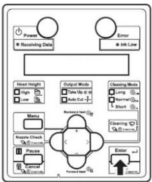
- Press the [Enter] key on Operation panel.

flowchart
graph TD
    A["Power"] --> B["Receiving Data"]
    C["Error"] --> D["Ink Low"]
    E["Head Height"] --> F["High"]
    E --> G["Low"]
    H["Output Mode"] --> I["Take Up (T)"]
    H --> J["Auto Cut"]
    K["Cleaning Mode"] --> L["Long"]
    K --> M["Normal"]
    K --> N["Short"]
    O["Menu"] --> P["Nozzle Check"]
    O --> Q["Pause"]
    O --> R["Cancel"]
    S["Forward Test"] --> T["Enter"]
    U["Feedback to"] --> V["-->"]
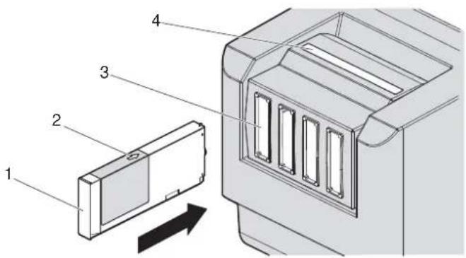
- "Insert InkCartridges" is displayed on Operation panel.
- Remove Cleaning fluid pack and IC chip card from High-capacity ink pack adapter.
NOTE
- When there is remaining Cleaning fluid pack and IC chip card, clarify the corresponding pack and card, and store it as a set.
-
Install Ink pack and IC chip card to High-capacity ink pack adapter.
-
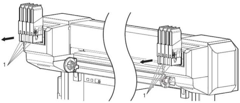
Install High-capacity ink pack adapters (K, C, M, Y: 2 each) in Ink cartridge slots (K, C, M, Y: 2 each) on the back of the printer.
• Shake High-capacity ink pack adapter 2 to 3 times lightly before installing it in Ink cartridge slot.
- Make sure that Ink packs are inserted into the correct Slots.
Match the ink color label with the ink color before inserting Ink pack.
NOTE
- Do not insert High-capacity ink pack adapter into Ink cartridge slot without attaching Ink pack. The information of the remaining IC chip card will be rewritten and Ink pack will not be usable.
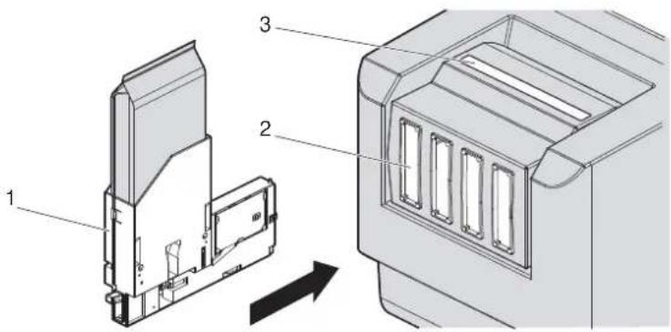
text_image
Technical diagram showing labeled components of a device housing or enclosure, with numbered parts and directional arrow indicating movement.| No. | Name |
| 1 | High-capacity ink pack adapter |
| 2 | Ink cartridge slots |
| 3 | Ink color labels |
- Insert High-capacity ink pack adapters all the way in Ink cartridge slots.
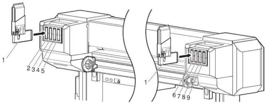
text_image
1 2 3 4 5 1 6 7 8 9| No. | Name |
| 1 | High-capacity ink pack adapter |
| 2 | Ink cartridge slot K1 |
| 3 | Ink cartridge slot K2 |
| 4 | Ink cartridge slot C1 |
| 5 | Ink cartridge slot C2 |
| 6 | Ink cartridge slot M1 |
| 7 | Ink cartridge slot M2 |
| 8 | Ink cartridge slot Y1 |
| 9 | Ink cartridge slot Y2 |
- When a High-capacity ink pack adapter is installed, "Ink Refill **%" is displayed on Operation panel and ink replenishment starts.
- Initial filling takes about 17 minutes. Ink filling operation and pause operation are repeated during the initial ink replenishment.
- When "100%" is displayed, the initial ink replenishment is complete.
• After the initial ink replenishment is complete, "Media End" is displayed on Operation panel.
CAUTION
- Comply strictly with the following during ink filling. If filling is interrupted, ink will be lost when filling is resumed.
- Do not turn OFF the power of the printer.
- Do not unplug the power cord set of the printer.
- Do not open Front cover.
- Do not open Maintenance cover.
- Do not raise Media loading lever.
NOTE
- If the printer perform the nozzle check printing immediately after the initial ink replenishment is complete, the following results may occur.
- Printed lines become blurred.
• The data is partially not printed.
In such cases, follow "5.3 Cleaning menu" and refill a small amount of ink. Then, check the printing result.
If there is no improvement in the print result even after refilling a small amount of ink, leave the printer unused for an hour or more. Then, refill a small amount of ink again and check the print result.
If there is still no improvement, contact your local MUTOH dealer.
3.3.5 When using High-capacity ink pack adapter for the first time on the printer whose ink is filled.
If the printer is used without the initial ink replenishment, the air inside High-capacity ink pack adapter goes into Ink tubes and may cause nozzle clogging. Perform the initial ink replenishment from Cleaning menu in the following cases.
- When using High-capacity ink pack adapter for the first time on the printer whose ink is filled
• After using High-capacity ink pack adapters and replacing them with new ones
5.3 Cleaning menu
3.4 Loading media
This section explains how to load and set media, and settings for each media type.
NOTE
• Refer to the following for details about handling media.
4.2 Media
- For types and details of the recommended media, contact your local MUTOH dealer.
3.4.1 Loading roll media
This section describes the procedure to load the roll media. Put the roll media in the center of the printer.
NOTE
- The following roll media can be loaded to this printer.
- Outer diameter: 150mm or less
• Media tube diameter: two inches or three inches
• Weight: 30kg or less - Width: 1,625 mm or less
• Thickness: 2.8mm or less
8.1.1 Printer specifications
Follow the procedure below to load the roll media.
- Loosen Fixing levers on the Roll media holders (both left and right) on the back of the printer. Set the distance between Roll media holders wider than the actual width of the roll media to be set.

text_image
Technical diagram of a mechanical device with numbered components and labeled parts, showing internal mechanisms and directional arrows.| No. | Name |
| 1 | Roll media holder (Left) |
| 2 | Roll media holder (Right) |
| 3 | Roll media |
| 4 | Fixing lever |
- Tighten Fixing lever of Roll media holder (Left) and fix the roll media holder (Left).

text_image
Technical diagram of a mechanical device with labeled components and an inset showing a circular component with numbered parts.| No. | Name |
| 1 | Roll media holder (Left) |
| 2 | Fixing lever |
- Set the roll media to Roll media holder (Left).

text_image
Technical diagram of a device with labeled components, showing internal wiring and connectors| No. | Name |
| 1 | Roll media holder (Left) |
| 2 | Roll media |
- Attach Roll media holder (Right) to the roll media and tighten Fixing lever.
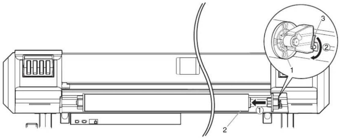
text_image
Technical diagram of a mechanical device with labeled components and an inset showing a close-up view of the internal structure.| No. | Name |
| 1 | Roll media holder (Right) |
| 2 | Roll media |
| 3 | Fixing lever |
- Loosen the fixing levers of the right and left roll media holders, move the roll media to the center and tighten the levers.
NOTE
- When tightening Fixing lever, press Roll media holder toward the printer. If you do not press Roll media holder, Fixing lever may not be completely locked because of the weight of the roll media.
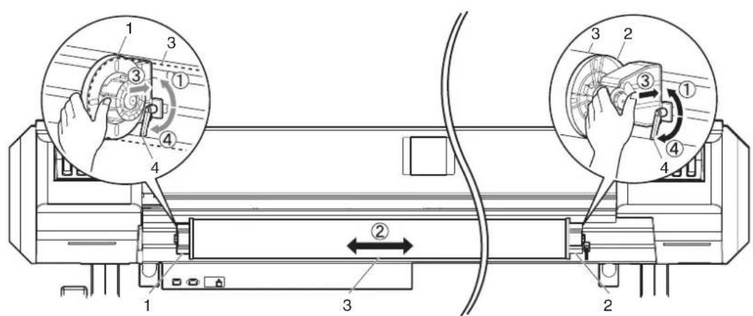
text_image
Technical diagram of a device with numbered components and labeled parts, showing hand operating controls and directional arrows.| No. | Name |
| 1 | Roll media holder (Left) |
| 2 | Roll media holder (Right) |
| 3 | Roll media |
| 4 | Fixing lever |
3.4.2 Setting Roll Media
This section explains how to set the roll media.
Follow the procedure below to set the roll media.
- Turn the printer ON.
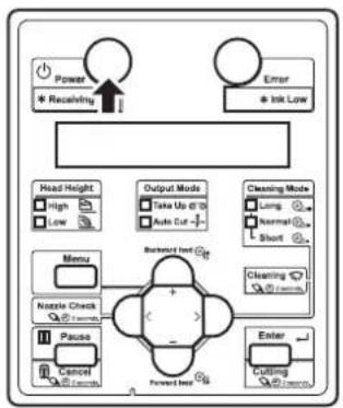
flowchart
graph TD
    A["Power"] --> B["Receiving"]
    C["Error"] --> D["Ink Low"]
    E["Head Height"] --> F["High"]
    E --> G["Low"]
    H["Output Mode"] --> I["Take Up @"]
    H --> J["Auto Cut"]
    K["Cleaning Mode"] --> L["Long"]
    K --> M["Normal"]
    K --> N["Short"]
    O["Menu"] --> P["Nzzle Check"]
    O --> Q["Pause"]
    O --> R["Cancel"]
    S["Backward Inlet"] --> T["+"]
    U["Forward Inlet"] --> V["-"]
    W["Enter"] --> X["Cutting"]
    Y["OK"] --> Z["OK"]

CAUTION
- Do not operate Media loading lever during initial operation. Print head may touch Pressurizing roller and cause a malfunction.
• The printer starts the initializing operation.
- "Media End" is displayed on Operation panel.
- Raise Media loading lever.

natural_image
Technical line drawing of a mechanical device with no visible text or symbols| No. | Name |
| 1 | Media loading lever |
- "Lever Up" is displayed on Operation panel.
- Open Front cover.

natural_image
Technical line drawing of a cylindrical industrial machine with attached control panel and base mount (no text or symbols)| No. | Name |
| 1 | Front cover |
- Set the roll media to Media feed slot.
NOTE
- If the end of the roll media is not wound tightly, wind it tightly again, and then load it.

natural_image
Technical line drawing of a mechanical device with labeled components (no text or symbols present)| No. | Name |
| 1 Roll media | |
| 2 | M e d i a f e e d s l o t |
- Pull the roll media out about 1 m from the front Media feed slot which is located inside of Front cover.
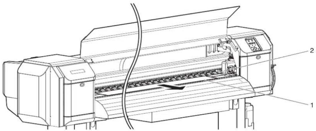
text_image
Technical line drawing of a printer with labeled parts 1 and 2, showing internal structure and wiring.| No. | Name |
| 1 Roll media | |
| 2 | M e d i a f e e d s l o t |
- Rewind the roll media a little by rolling Flange on Roll media holder while holding the edge of the media, and eliminate any slack or slant.
NOTE
- If you set the roll media free while rewinding, the roll media may fall out from Media feed slot and fall toward the back of the printer.
- Confirm that the right edge of the roll media does not go beyond the loading mark. If it does, it may affect print quality.
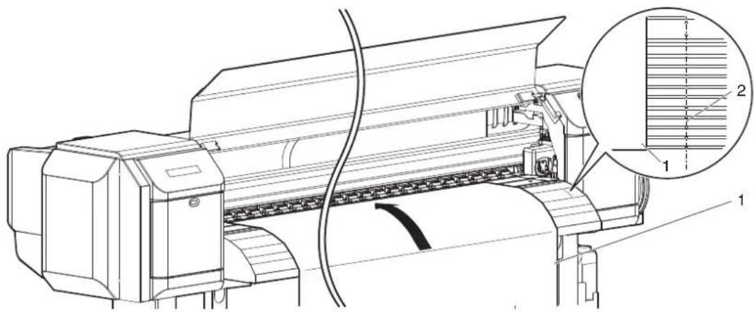
text_image
Technical line drawing of a printer with labeled parts and an inset magnified view showing internal structure.| No. Name |
| 1 Roll media |
| 2 Media loading mark |
- Make sure that the edges of the media is appropriately pressed by Pressurizing rollers.
When the media is set as shown in the following figure X, follow the procedure to adjust the position of the roll media.
If the media is set as shown in the following figure X, the media may be misaligned or creased during printing.

text_image
Technical diagram of a printer with labeled parts and zoomed-in insets showing internal components| No. | Name |
| 1 | Roll media |
| 2 | Pressurizing rollers |

text_image
5mm 1 2
text_image
X 2 5mm 1
text_image
X 2 5mm 1| No. | Name |
| 1 | Roll media |
| 2 | Pressurizing rollers |

text_image
1 2
text_image
1 2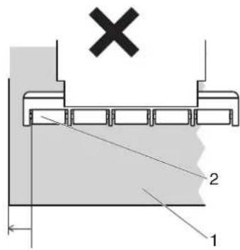
text_image
X 2 1| No. Name |
| 1 Roll media |
| 2 Pressurizing rollers |
a. Loosen Fixing levers of the right and left Roll media holders, and move the roll media to left or right.
b. After moving the roll media, fix it with Fixing levers of the right and left Roll media holders.
NOTE
- When tightening Fixing lever, press Roll media holder toward the printer. If you do not press Roll media holder, Fixing lever may not be completely locked because of the weight of the roll media.

text_image
Technical diagram of a washing machine with numbered components and labeled parts, showing hand operating controls and internal mechanism.| No. | Name |
| 1 | Roll media holder (Left) |
| 2 | Roll media holder (Right) |
| 3 | Roll media |
| 4 | Fixing lever |
- Lower Media loading lever.
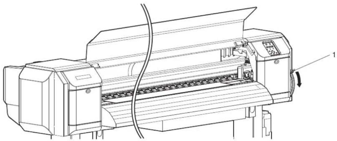
natural_image
Technical line drawing of a printer with internal components and a cable, no visible text or symbols| No. | Name |
| 1 | Media loading lever |
NOTE
- When loading the new roll media, cut the front edge of the media if it is not straight. 14.4.3 Cutting media
- When you increase the pressure for the media, lower Media loading lever further as shown below.

natural_image
Technical line drawing of a printer with internal components and cable, no visible text or symbols| No. | Name |
| 1 | Media loading lever |
- Close Front cover.

natural_image
Technical line drawing of a printer with paper feed and cable, no visible text or symbols| No. | Name |
| 1 | Front cover |
- The User Type Setup menu is displayed on Operation panel.
TIP
- To change the user type, follow "3.4.3 Setting the User Type Setting" and set the user type.
3.4.3 Setting the User Type Setting
This section explains how to set the user type setting.
Follow the procedure below to set the user type setting.
- Turn ON the printer and load the media.
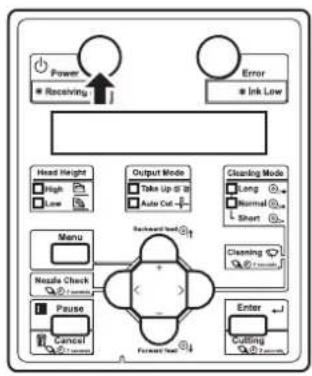
flowchart
graph TD
    A["Power"] --> B["Receiving"]
    C["Error"] --> D["Ink Low"]
    E["Head Height"] --> F["High"]
    E --> G["Low"]
    H["Output Mode"] --> I["Take Up @ 10"]
    H --> J["Auto Out"]
    K["Cleaning Mode"] --> L["Long"]
    K --> M["Normal"]
    K --> N["Short"]
    O["Menu"] --> P["Nozzle Check"]
    O --> Q["Pause"]
    O --> R["Cancel"]
    S["Forward Test"] --> T["Enter"]
    U["Cutting"] --> V["Forward Test"]
    W["Backward Test"] --> X["Forward Test"]
• After loading the media, the printer enters the User Type Setting menu.
TIP
• Refer to the following for setting the media.
3.4.2 Setting Roll Media
- Refer to the following for details on the User Type Setting menu.
5.1.1 User Type menu
- Press the [+] key or [-] key on Operation panel to select the User Type Setting.
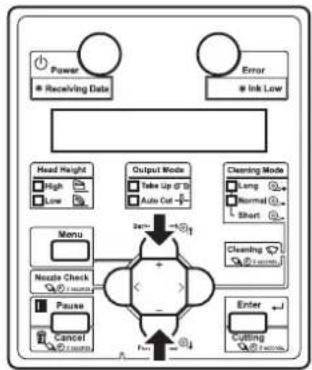
flowchart
graph TD
    A["Power"] --> B["Receiving Data"]
    C["Error"] --> D["Ink Low"]
    E["Head Height"] --> F["High"]
    E --> G["Low"]
    H["Menu"] --> I["Noodle Check"]
    H --> J["Pause"]
    H --> K["Cancel"]
    L["Output Mode"] --> M["Take Up @ 10"]
    L --> N["Auto Cut"]
    O["Cleaning Mode"] --> P["Sang"]
    O --> Q["Normal"]
    O --> R["Short"]
    S["Nozzle Check"] --> T["Enter"]
    U["Enter"] --> V["Cutting"]
    W["Enter"] --> X["Cutting"]
- Press the [Enter] key on Operation panel.

flowchart
graph TD
    A["Power"] --> B["* Receiving Data"]
    C["Error"] --> D["* Ink Low"]
    E["Head Height"] --> F["High"]
    E --> G["Low"]
    H["Menu"] --> I["Nextie Check"]
    H --> J["Pause"]
    H --> K["Control"]
    L["Output Mode"] --> M["Take Up @ 30"]
    L --> N["Auto Cut -"]
    O["Cleaning Mode"] --> P["Long"]
    O --> Q["Normal"]
    O --> R["Short"]
    S["Backward Event"] --> T["Forward Event"]
    U["Enter"] --> V["Forward"]
• The user type setting is set.
- "Media Initial" is displayed on Operation panel and media initialization starts.
NOTE
- If the following operations are performed in the User Type Setting menu, the printer starts media initial operation without changing the User Type setting.
- Pressing the [Cancel] key on Operation panel.
-
No keys on Operation panel are pressed for ten seconds.
-
After media initial operation is complete, "Ready to Print" is displayed on Operation panel and the printer status shifts to Normal.
• Media set is complete.
3.4.4 Changing Torque of Roll Media Holder
This section explains how to change the torque setting of the Roll media holder.
The 1 kg torque is usually used. When the media is creased or the print head might have a risk of striking the media, change to the 4 kg torque.
Follow the procedure below to change the torque setting of the Roll media holders.
- Rotate the damper knob placed at the Roll media holder (the back left and right of the printer) by 90 degrees while pulling it out.
- When you rotate the damper knob by 90 degrees, it clicks into place. Rotating the damper knob by 90 degrees alternately changes the 1 kg torque and 4 kg torque.
- Change the torque setting for both of the Roll media holders.
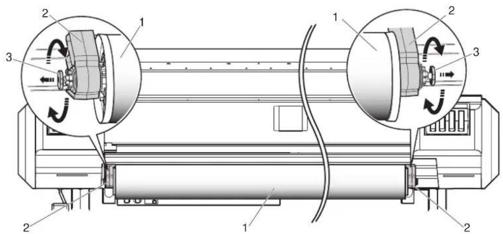
text_image
Technical diagram of a mechanical device with labeled components and rotational indicators| No. | Name |
| 1 | M e d i a |
| 2 Roll media holder | |
| 3 Damper knob | |
- AETorque can be set to either 1kg or 4kg as below.
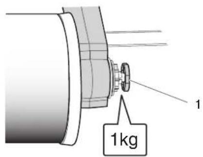
text_image
1 1kg
text_image
1 4kg| No. | Name |
| 1 | Damper knob |
3.5 Test print
Follow the procedure below to perform test printing to confirm that the printer works correctly.
- Turn ON the printer and load the roll media.
3.4.2 Setting Roll Media
-
Confirm that the printer is in the Normal status.
-
Display the Test Print menu on Operation panel.
a. Press the [Menu] key on Operation panel.
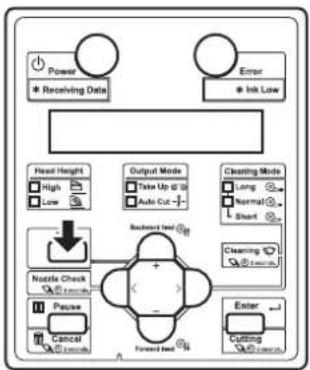
flowchart
graph TD
    A["Power"] --> B["Receiving Data"]
    C["Error"] --> D["Ink Low"]
    E["Head Height"] --> F["High"]
    E --> G["Low"]
    H["Output Mode"] --> I["Take Up @ 32"]
    H --> J["Auto Cut -"]
    K["Cleaning Mode"] --> L["Long"]
    K --> M["Normal"]
    K --> N["Short"]
    O["Nottle Check"] --> P["+"]
    Q["Pause"] --> R["Cancel"]
    S["Forward Test"] --> T["Cutting"]
    U["Enter"] --> V["Cutting"]
- "Menu1: Setup>" is displayed on Operation panel.
b. Press the [+] key or [-] key on Operation panel to select "Menu2: Test Print".
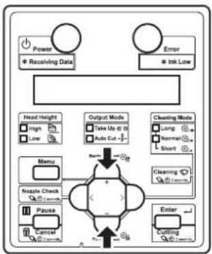
flowchart
graph TD
    A["Power"] --> B["* Receiving Data"]
    C["Error"] --> D["* Ink Low"]
    E["Head Height"] --> F["High"]
    E --> G["Low"]
    H["Menu"] --> I["Nzzle Check"]
    H --> J["Pause"]
    H --> K["Cancel"]
    L["Output Mode"] --> M["Take Up @ 0"]
    L --> N["Auto Cut -"]
    O["Cleaning Mode"] --> P["Long"]
    O --> Q["Normal"]
    O --> R["Short"]
    S["Enter"] --> T["Cutting"]
    U["+"] --> V["+"]
    W["+"] --> X["-"]
c. Press the [>] key on Operation panel.
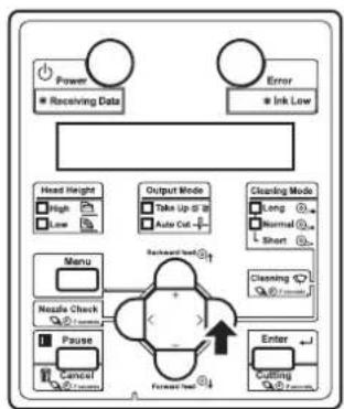
flowchart
graph TD
    A["Power"] --> B["Receiving Data"]
    C["Error"] --> D["Ink Low"]
    E["Head Height"] --> F["High"]
    E --> G["Low"]
    H["Output Mode"] --> I["Take Up to 30"]
    H --> J["Auto Cut"]
    K["Cleaning Mode"] --> L["Long"]
    K --> M["Normal"]
    K --> N["Short"]
    O["Menu"] --> P["Nesle Check"]
    O --> Q["Pause"]
    R["Enter"] --> S["Cutting"]
    R --> T["Forward Incl"]
    U["Backward Incl"] --> V["+"]
    W["Forward Incl"] --> X["↓"]
- "Test1: Nozzle Check" is displayed on Operation panel.
- The display shifts to the Test Print menu.
5.2 Test Print Menu
-
Press the [+] key or [-] key on Operation panel to select an item for printing from the following items.
-
Nozzle Check
- Mode Print
- Setup List
- Palette
NOTE
- When the selected print mode of the user type is Graphics 1 or Graphics 2, Palette menu is not displayed.
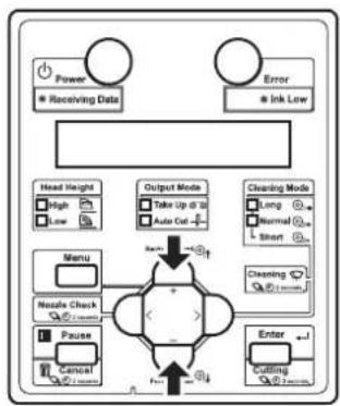
flowchart
graph TD
    A["Power"] --> B["Receiving Data"]
    C["Error"] --> D["Ink Low"]
    E["Head Height"] --> F["High"]
    E --> G["Low"]
    H["Menu"] --> I["Noise Check"]
    H --> J["Pause"]
    H --> K["Cancel"]
    L["Output Mode"] --> M["Take Up at 10"]
    L --> N["Auto Cut"]
    O["Cleaning Mode"] --> P["Long"]
    O --> Q["Normal"]
    O --> R["Short"]
    S["Nozzle Check"] --> T["+"]
    U["Pause"] --> V["+"]
    W["Enter"] --> X["Cutting"]
- Press the [Enter] key on Operation panel.

flowchart
graph TD
    A["Power"] --> B["Receiving Data"]
    C["Error"] --> D["Ink Low"]
    E["Head Height"] --> F["High"]
    E --> G["Low"]
    H["Menu"] --> I["Nextle Check"]
    H --> J["Pause"]
    H --> K["Control"]
    L["Output Mode"] --> M["Take Up @ 10"]
    L --> N["Auto Cut -"]
    O["Cleaning Mode"] --> P["Long"]
    O --> Q["Normal"]
    O --> R["Short"]
    S["Cleaning"] --> T["Forward Load"]
    U["Enter"] --> V["Forward Load"]
    W["Forward Load"] --> X["Forward Load"]
- Start performing Test Print for the selected item.
TIP
• Refer to the following for details on each of the print list items.
1 3.5.1 Nozzle check to 3.5.3 Setup print
-
Repeat step 4 to step 5 when performing test print for other items.
-
Press the [Menu] key on Operation panel to exit from test print.

flowchart
graph TD
    A["Power\n* Receiving Data"] --> B["Error\n* Ink Low"]
    C["Head Height\nHigh\nLow"] --> D["Nozzle Check\n+/-/unknown"]
    E["Output Mode\nTake Up @ 10\nAuto Cut -/-"] --> F["Forward test"]
    G["Cleaning Mode\nLong\nLow\nNormal\nShort"] --> H["Enter\nCutting\n+/-/unknown"]
    I["Nozzle Check\n+/-/unknown"] --> J["Pause\nCancel\n+/-/unknown"]
    K["Backward test"] --> L["Forward test"]
• Operation panel returns to Normal.
• The procedure for test printing is complete.
3.5.1 Nozzle check
It is used to check whether there are any clogged heads, or missing/blurred prints.
NOTE
- If the nozzle check result shows that the checked points are blurred or missing, perform head cleaning.
6.2.3 Head cleaning
Perform nozzle check once again at the end of the work.
TIP
• Refer to the following for printing procedure.
3.5 Test print

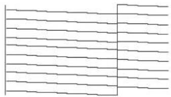
natural_image
Pure electrical circuit lines without any symbols
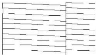
natural_image
Abstract pattern of horizontal lines and a vertical bar (no text or symbols)3.5.2 Mode print
Used to confirm the following printing conditions.
- PrintMode
- Effect
• Pre-heater set temperature (VJ-1638 only) - Platen heater set temperature (VJ-1638 only)
• After heater set temperature (VJ-1638 only)
• Media feed compensation micro adjustment value
TIP
• Refer to the following for printing procedure.
3.5 Test print
2011/10/01 0:00 G2(720x1080 6Pass Bi)-Fine&Fog/Pre:30°C/Platen:30°C/After:30°C/PF Adjust:0.00%
2011/10/01 0:00 G2(720x1080 6Pass Bi)-Fine&Fog /PF Adjust:0.00%
3.5.3 Setup print
Used to check the current setup of the printer.
NOTE
- Keep the printed setup print at hand.
TIP
• Refer to the following for printing procedure.
3.5 Test print
• The illustrations used in this section are print samples of VJ-1638.
Setup List
| 2011/05/01 0:00 | ||
| Serial No. = XS00000001Model = X4 1618 Firmware No= 9 1.00 Memory Size = 250KB | |Error!0 : None [ ]1 : None [ ] | 2 : None [ ]2 : None [ ]3 : None [ ]4 : None [ ] |
| Head Height : Low Cleaning Mode: Normal | ||
| [Number] Setup\Name = SetupT1/T*User Type = Type I{1}Print Mode = Quality (Effect - Fines?Top){2}Adjust Print{3}PF Adjust{1}Initial Adj. Print{2} initial Adj = 250.0/250mm{3}OnTime Adj. Print{4}None Adj. Print{5}None Adj = 0.0%{6}Injector = 20°C{7}Pointer = 20°C{8}Driver = 20°C{9}Vacuum Fan = High{10}[+]Sulfiting = Do(Pause Count = 1cm]{11}[+]Side Margin = 5ms{12}[+]Media In Lai = Midh{13}[+]Main Make = 1000mm{14}[+]Output Make = Off(IndProduct ware = Odd){15}[+]Method or Cut = Sing out-Stop{16}[+]Origin{17}[+]Prevent Stick = Off{18}[+]Scanby Reset = Midh{19}[+]Mouse Tranav = Data{20}[+]Multi Strike = load{21}[+]Drive Init = 0.0mm{22}[+]Down Slot = On | [Number][Source]Name = Setup{10}T*Auto CleaningNoitingTime = 360minPrintingTime = OffBefore Pris = Off{11}T* Ink Stazout SmartChip K&Co ---/---Mally ---/---{12}[+]R#1Kind = Off{13}[+]Kocust Fan = Low{14}T* Longstore{20}T* DB Maintenance{21}T* Initial Location{22}L* Life Time Read1 : C★★★★FRead2 : F★★★★FFunc1 : C★★★★FCurs2 : C★★★★FCR Nator : F★★★★FP Nator : F★★★★F{23}T* IP Address = 192.150.001.262{24}T* Sunset Work = 250.250.250.200{25}T* Gateway = 192.150.001.254SteedModeTimer = 6cLanguage = EnglishUsagename = 0.0lmv[C]Length = mn | |
| User TypePrint ModeEffectPDInitial Adjust:PFMicro Adjust:Praktifier:Plantsulator:Dryer:Vacuum Fan | Type 1Graphics 2A-B: FineDiffuse250, 0/250cmC:00%30°C30°C30°CHigh | Type 2Graphics 2FineDiffuse250, 0/250cm0.00%30°C30°C30°CHigh | Type 3Graphics 2FineDiffuse250, 0/250cmC:00%30°C30°C30°CHigh | Type 4Graphics 2FineDiffuse250, 0/250cm0.00%30°C30°C30°CHigh | Type 5Graphics 2FineDiffuse250, 0/250cmC:00%30°C30°C30°CHigh |
| User TypePrint ModeEffectPDInitial Adjust:PFMicro Adjust:Praktifier:Plantsulator:Dryer:Vacuum Fan | Type 6Graphics 2FineDiffuse250, 0/250cmC:00%30°C30°C30°CHigh | Type 7Graphics 2FineDiffuse250, 0/250cm0.00%30°C30°C30°CHigh | Type 8Graphics 2FineDiffuse250, 0/250cmC:00%30°C30°C30°CHigh | Type 9Graphics 2FineDiffuse250, 0/250cm0.00%30°C30°C30°CHigh | Type10Graphics 2FineDiffuse250, 0/250cmC:00%30°C30°C30°CHigh |
| User TypePrint ModeEffectPDInitial Adjust:PFMicro Adjust:Praktifier:Plantsulator:Dryer:Vacuum Fan | Type11Graphics 2FineDiffuse250, 0/250cmC:00%30°C30°C30°CHigh | Type12Graphics 2FineDiffuse250, 0/250cm0.00%30°C30°C30°CHigh | Type13Graphics 2FineDiffuse250, 0/250cmC:00%30°C30°C30°CHigh | Type14Graphics 2FineDiffuse250, 0/250cm0.00%30°C30°C30°CHigh | Type15Graphics 2FineDiffuse250, 0/250cmC:00%30°C30°C30°CHigh |
3.5.4 Palette print
Palette printing is performed as a color demonstration.
NOTE
- When the selected print mode of the user type is Graphics 1 or Graphics 2, Palette menu is not displayed.
TIP
• Refer to the following for printing procedure.
3.5 Test print

other
| PEN NUMBER | PRIMARY COLORS | GRAY LEVELS | | ---------- | -------------- | ----------- | | 1 | 0 | 0 | | 2 | 0 | 0 | | 3 | 0 | 0 | | 4 | 0 | 0 | | 5 | 0 | 0 | | 6 | 0 | 0 | | 7 | 0 | 0 | | 8 | 0 | 0 | | 9 | 0 | 0 | | 10 | 0 | 0 | | 11 | 0 | 0 | | 12 | 0 | 0 | | 13 | 0 | 0 | | 14 | 0 | 0 | | 15 | 0 | 0 |3.6 Print quality adjustment
It is used for optimizing the quality of image prints.
Adjustment methods for this printer are as follows.
| Adjustment method | Description Reference | |
| Standard Adjusts only | the print mode in the user type setting which is currently set. | 3.6.1 Standard print quality adjustment |
| Custom Perform adjustment for all print modes. | 3.6.2 Custom print quality adjustment | |
NOTE
- This printer was adjusted at the factory shipment so that it obtains the optimum printing quality. Adjust the quality if the print quality changes after the installation environment or the media is changed.
- When newly setting or changing the user type setting after adjusting Standard adjust print, make sure to adjust print.
- Since all print modes are adjusted at once after performing Custom adjust print, adjust print is not required even after changing the print mode.
- When specifying a print mode which is different from the mode set in the user type setting, adjust all print modes in the Custom adjust print first.
3.6.1 Standard print quality adjustment
Adjusts only the print mode in the user type setting which is currently set. This menu consists of the following menus.
| Menu name Description | Option Reference | |
| Standard confirmation pattern | Print out the confirmation pattern and check the degree of misalignment. | 3.6.1.1 Standard confirmation pattern |
| Standard rough adjustment pattern | Perform this when the degree of misalignment is big. | 3.6.1.2 Standard rough adjustment pattern |
| Standard micro adjustment pattern | Perform this when the degree of misalignment is small. | 3.6.1.3 Standard micro adjustment pattern |
Follow the procedure below to perform adjustment.
- Print out the confirmation pattern and check the degree of misalignment.
3.6.1.1 Standard confirmation pattern
- Perform rough adjustment when the degree of misalignment is big.
3.6.1.2 Standard rough adjustment pattern Perform micro adjustment when the degree of misalignment is small. 3.6.1.3 Standard micro adjustment pattern
NOTE
- Perform rough adjustment first when the degree of misalignment is difficult to determine.
- Print out the confirmation pattern again and check if the printer has been adjusted properly.
3.6.1.1 Standard confirmation pattern
- If it has not been adjusted yet, return to step 2.
NOTE
- Perform micro adjustment if the printer is not fully adjusted after rough adjustment.
3.6.1.1 Standard confirmation pattern
Print out the confirmation pattern of the print mode in the user type setting which is currently set.
- Turn ON the printer and load the roll media.
3.4.2 Setting Roll Media
- Display the Adjust Print menu on Operation panel.
a. Press the [Menu] key on Operation panel.
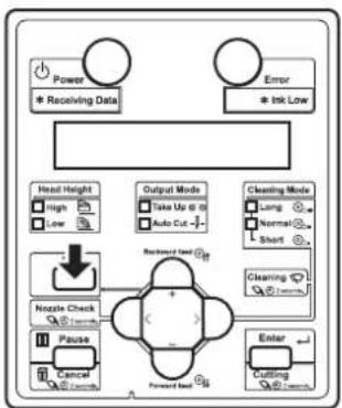
flowchart
graph TD
    A["Power\n* Receiving Data"] --> B["Head Height"]
    C["Error\n* Ink Low"] --> D["Output Mode\nTake Up @ 0\nAuto Cut -"]
    E["Nozzle Check"] --> F["Noise Check"]
    G["Pause"] --> H["Cancel"]
    I["Enter"] --> J["Cutting"]
    K["Cleaning Mode"] --> L["Long"]
    M["Normal"] --> N["Short"]
    O["Backward Load"] --> P["+"]
    Q["Forward Load"] --> R["-"]
- "Menu1: Setup>" is displayed on Operation panel.
b. Press the [>] key on Operation panel to select "Menu1: User Type".

flowchart
graph TD
    A["Power"] --> B["Receiving Data"]
    C["Error"] --> D["Ink Low"]
    E["Head Height"] --> F["High"]
    E --> G["Low"]
    H["Menu"] --> I["Nzzle Check"]
    H --> J["Pause"]
    K["Enter"] --> L["Cutting"]
    M["Output Mode"] --> N["Take Up to 30"]
    M --> O["Auto Cut"]
    P["Cleaning Mode"] --> Q["Long"]
    P --> R["Normal"]
    P --> S["Short"]
    T["Start"] --> U["Cleaning"]
    V["Start"] --> W["End"]
c. Press the [Enter] key on Operation panel.
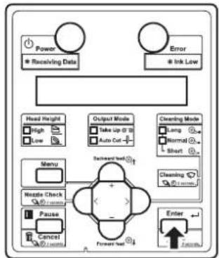
flowchart
graph TD
    A["Power"] --> B["Receiving Data"]
    C["Error"] --> D["Ink Low"]
    E["Head Height"] --> F["High"]
    E --> G["Low"]
    H["Output Mode"] --> I["Take Up @ 3"]
    H --> J["Auto Cut +"]
    K["Cleaning Mode"] --> L["Long"]
    K --> M["Normal"]
    K --> N["Short"]
    O["Menu"] --> P["Nozzle Check"]
    Q["Nzzle Check"] --> R["Pause"]
    S["Cancel"] --> T["Launch"]
    U["Enter"] --> V["Forward Event"]
    W["Forward Event"] --> X["Forward Event"]
    Y["Forward Event"] --> Z["Forward Event"]
- "User: TypeXX" (XX is a number between 1 and 15) is displayed on Operation panel. d. Press the [+] key or [-] key on Operation panel to select the user type setting. e. Press the [Enter] key on Operation panel.
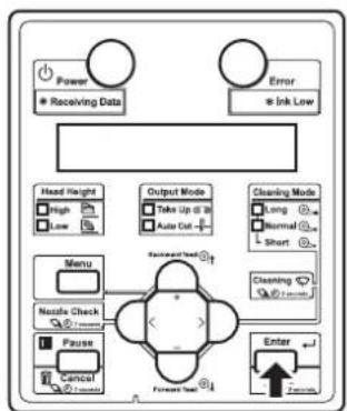
flowchart
graph TD
    A["Power"] --> B["Receiving Data"]
    C["Error"] --> D["Ink Low"]
    E["Head Height"] --> F["High"]
    E --> G["Low"]
    H["Output Mode"] --> I["Take Up to 20"]
    H --> J["Auto Cut"]
    K["Cleaning Mode"] --> L["Long"]
    K --> M["Normal"]
    K --> N["Short"]
    O["Menu"] --> P["Nostale Check"]
    O --> Q["Pause"]
    O --> R["Cancel"]
    S["Forward Event"] --> T["Forecast Event"]
    U["Enter"] --> V["7 seconds"]
- "**1: Print Mode" is displayed on Operation panel.
f. Press the [+] key or [-] key on Operation panel to select "Menu2: Adjust Print".

flowchart
graph TD
    A["Power"] --> B["* Receiving Data"]
    C["Error"] --> D["* Ink Low"]
    E["Head Height"] --> F["High"]
    E --> G["Low"]
    H["Menu"] --> I["Nazole Check"]
    H --> J["Pause"]
    H --> K["Control"]
    L["Output Mode"] --> M["Take Up @ 10"]
    L --> N["Auto Cut -"]
    O["Cleaning Mode"] --> P["Long"]
    O --> Q["Normal"]
    O --> R["Short"]
    S["Enter"] --> T["Cutting"]
    U["Start"] --> V["Cutting"]
    W["Start"] --> X["Cutting"]
    Y["Start"] --> Z["Cutting"]
    style A fill:#fff,stroke:#333
    style C fill:#fff,stroke:#333
    style E fill:#fff,stroke:#333
    style L fill:#fff,stroke:#333
    style O fill:#fff,stroke:#333
    style U fill:#fff,stroke:#333
    style V fill:#fff,stroke:#333
    style X fill:#fff,stroke:#333
    style Y fill:#fff,stroke:#333
g. Press the [>] key on Operation panel.
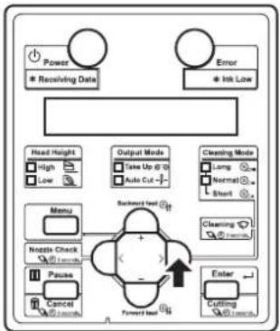
flowchart
graph TD
    A["Power<br>* Receiving Date"] --> B["Error<br>* Ink Low"]
    C["Head Height<br>High Low"] --> D["Output Mode<br>Take Up @ 10<br>Auto Cut -"]
    E["Menu"] --> F["Backward Test"]
    G["Nzzle Check<br>10000000000"] --> H["Pause<br>Cancel 1000000000"]
    I["Enter"] --> J["Cutting 1000000000"]
    K["Clearing Mode<br>Long Normal Short"] --> L["Clearing 1000000000"]
    M["Forward Test"] --> N["+"]
    O["OK"] --> P["+"]
- "Adjust print1: Standard" is displayed on Operation panel.
h. Press the [+] key or [-] key on Operation panel to select "Adjust Print1: Standard".

flowchart
graph TD
    A["Power"] --> B["* Receiving Data"]
    C["Error"] --> D["* Ink Low"]
    E["Head Height"] --> F["High"]
    E --> G["Low"]
    H["Menu"] --> I["Noise Check"]
    J["Pause"] --> K["Control"]
    L["Event"] --> M["Cutting"]
    N["Output Mode"] --> O["Take Up @ 20"]
    N --> P["Auto Cut -"]
    Q["Cleaning Mode"] --> R["Long"]
    Q --> S["Normal"]
    Q --> T["Short"]
    U["Cleaning Mode"] --> V["Short"]
    W["+/-"] --> X["+/-"]
    Y["+/-"] --> Z["-/-"]
i. Press the [Enter] key on Operation panel.

flowchart
graph TD
    A["Power"] --> B["Receiving Data"]
    C["Error"] --> D["Ink Low"]
    E["Head Height"] --> F["High"]
    E --> G["Low"]
    H["Output Mode"] --> I["Data Up to 28"]
    H --> J["Auto Cut"]
    K["Cleaning Mode"] --> L["Long"]
    K --> M["Normal"]
    K --> N["Short"]
    O["Menu"] --> P["Nozzle Check"]
    O --> Q["Pause"]
    O --> R["Cancel"]
    S["Forward Test"] --> T["Enter"]
    U["Forward Test"] --> V["Enter"]
- "Adj.1: Confirm" is displayed on Operation panel.
• The display enters the Adjust Print menu.
5.1.1.1.2 Adjust Print menu
- Press the [Enter] key on Operation panel.
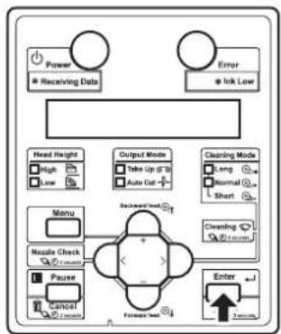
flowchart
graph TD
    A["Power"] --> B["Receiving Data"]
    C["Error"] --> D["Ink Low"]
    E["Head Height"] --> F["High"]
    E --> G["Low"]
    H["Output Mode"] --> I["Take Up Of 10"]
    H --> J["Auto Cut"]
    K["Cleaning Mode"] --> L["Long"]
    K --> M["Normal"]
    K --> N["Short"]
    O["Menu"] --> P["Nozzle Check"]
    O --> Q["Pause"]
    O --> R["Cancel"]
    S["Forward User"] --> T["Enter"]
    U["Forward User"] --> V["Enter"]
- For VJ-1638, "Warming Up Skip ->E" is displayed on Operation panel. (This is not displayed for VJ-1638W since it does not perform warming up.)
CAUTION
- While "Warming Up" is displayed, do not touch Platen and Media guide. They become very hot and you could burn yourself.
NOTE
- You can start printing during warming up. 4.4.7 Starting printing during warming up (VJ-1638 only)
- A confirmation pattern for print quality adjustment is printed. (VJ-1638 starts printing after warming up is complete.)
• The confirmation pattern will be printed.
NOTE
- Because this printer has 2 Print heads, 2 rows of confirmation pattern will be printed.
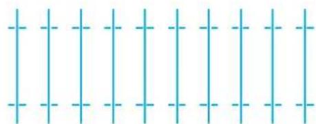
natural_image
Pure grid pattern with vertical and horizontal lines, no text or symbols present
natural_image
Pure grid pattern with vertical and horizontal lines, no text or symbols present• After the confirmation pattern is printed, Operation panel returns to "Adj.1: Confirm".
- Confirm that the confirmation pattern printing result is as follows.

text_image
Diagram showing a grid with X and O symbols and a transformation arrow, likely illustrating a mathematical or logical concept.a. When the printing result is OK; You do not need perform print quality adjustment. The procedure for print quality adjustment is complete.
b. When the printing result is NG; You need to perform print quality adjustment. - Perform rough adjustment when the degree of misalignment is big. 3.6.1.2 Standard rough adjustment pattern - Perform micro adjustment when the degree of misalignment is small. 3.6.1.3 Standard micro adjustment pattern
3.6.1.2 Standard rough adjustment pattern
Perform rough adjustment when the degree of misalignment is big. Print rough adjustment pattern and register the set values.
-
Display the Standard Adjust Print menu on Operation panel in the same way as step 2 of 3.6.1.1 Standard confirmation pattern.
-
Press the [+] key or [-] key on Operation panel to select "Adj.2: Rough Pattern".
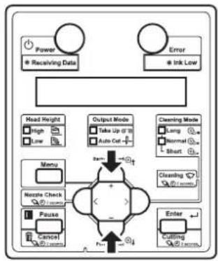
flowchart
graph TD
    A["Power"] --> B["Receiving Data"]
    C["Error"] --> D["Ink Low"]
    E["Head Height"] --> F["High"]
    E --> G["Low"]
    H["Menu"] --> I["Nzzle Check"]
    H --> J["Pause"]
    H --> K["Cancel"]
    L["Output Mode"] --> M["Take Up @ 10"]
    L --> N["Auto Cut"]
    O["Cleaning Mode"] --> P["Long"]
    O --> Q["Normal"]
    O --> R["Short"]
    S["Enter"] --> T["Cutting"]
    U["Zoom"] --> V["+"]
    W["+"] --> X["-"]
    Y["+"] --> Z["-"]
    style A fill:#fff,stroke:#333
    style C fill:#fff,stroke:#333
    style E fill:#fff,stroke:#333
    style L fill:#fff,stroke:#333
    style O fill:#fff,stroke:#333
    style U fill:#fff,stroke:#333
    style V fill:#fff,stroke:#333
    style W fill:#fff,stroke:#333
    style X fill:#fff,stroke:#333
    style Y fill:#fff,stroke:#333
- Press the [Enter] key on Operation panel.

flowchart
graph TD
    A["Power"] --> B["Receiving Data"]
    C["Error"] --> D["Ink Low"]
    E["Head Height"] --> F["High"]
    E --> G["Low"]
    H["Output Mode"] --> I["Take Up & 10"]
    H --> J["Auto Out"]
    K["Cleaning Mode"] --> L["Long"]
    K --> M["Normal"]
    K --> N["Short"]
    O["Menu"] --> P["Nozzle Check"]
    O --> Q["Pause"]
    O --> R["Cancel"]
    S["Forward User"] --> T["Enter"]
    U["Forward User"] --> V["Enter"]
- For VJ-1638, "Warming Up Skip ->E" is displayed on Operation panel. (This is not displayed for VJ-1638W since it does not perform warming up.)
CAUTION
- While "Warming Up" is displayed, do not touch Platen and Media guide. They become very hot and you could burn yourself.
NOTE
- You can start printing during warming up. 4.4.7 Starting printing during warming up (VJ-1638 only)
- A rough adjustment pattern is printed for both Head 1 and Head 2. (VJ-1638 starts printing after warming up is complete.)

text_image
Pattern for Head 1 21 20 19 18 17 16 15 14 13 12 11 10 9 8 7 6 5 4 3 2 1 Pattern for Head 2 123456789101112134415161718192021- For the rough adjustment pattern, the same patterns will be printed on both sides and center of the media.
- For Head 1, check the print results on both sides and center of the media and select the number that looks most aligned between 1 and 21.
• 12 is selected in the next printing sample.

text_image
15 14 13 12 11 21 20 19 18 17 16 15 14 13 12 11 10 9 8 7 6 5 4 3 2 1NOTE
• 11 represents the current setting value.
- "Pattern*1: 11" (refer to the chart below for *) is displayed on Operation panel.
- The pattern name indicated by * differs depending on the set print mode. Print modes and corresponding pattern names are listed as follows.
| PrintMode Pattern name | |
| Quality 1, 2 C | |
| Quality 3, 4 B | |
| Graphics 1, 2 B | |
| Banner 1, 2 A | |
| Banner 3, 4 A |
NOTE
- Refer to the following for Print mode. 5.1.1.1.1 Print Mode menu
- Press the [+] key or [-] key on Operation panel to enter the number that you selected in Step 4.
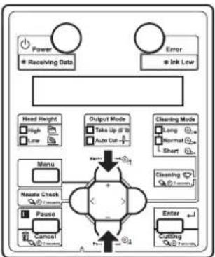
flowchart
graph TD
    A["Power"] --> B["Receiving Data"]
    C["Error"] --> D["Ink Low"]
    E["Head Weight"] --> F["Menu"]
    G["Output Mode"] --> H["Take Up @ 10"]
    G --> I["Auto Out"]
    J["Cleaning Mode"] --> K["Long"]
    J --> L["Normal"]
    J --> M["Short"]
    N["Neate Check"] --> O["Pause"]
    N --> P["Cancel"]
    Q["Enter"] --> R["Cutting"]
    S["Input"] --> T["+"]
    U["Feedback"] --> V["-"]
    W["Feedback"] --> X["-"]
    Y["Feedback"] --> Z["-"]
    style A fill:#fff,stroke:#333
    style C fill:#fff,stroke:#333
    style E fill:#fff,stroke:#333
    style J fill:#fff,stroke:#333
    style N fill:#fff,stroke:#333
    style Q fill:#fff,stroke:#333
    style S fill:#fff,stroke:#333
    style U fill:#fff,stroke:#333
    style V fill:#fff,stroke:#333
    style W fill:#fff,stroke:#333
    style X fill:#fff,stroke:#333
    style Y fill:#fff,stroke:#333
    style Z fill:#fff,stroke:#333
NOTE
- When you press the [Cancel] key on Operation panel, the setting value is not entered and the display returns to "Adj.2: Rough Pattern".
- Press the [Enter] key on Operation panel.
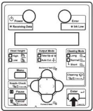
flowchart
graph TD
    A["Power"] --> B["* Receiving Data"]
    C["Error"] --> D["* Ink Low"]
    E["Head Height"] --> F["High"]
    E --> G["Low"]
    H["Menu"] --> I["Nzzle Check"]
    H --> J["Pause"]
    H --> K["Control"]
    L["Output Mode"] --> M["Take Up @ 10"]
    L --> N["Auto Cut -"]
    O["Cleaning Mode"] --> P["Long"]
    O --> Q["Normal"]
    O --> R["Short"]
    S["Forward Load"] --> T["Backward Load"]
    U["Enter"] --> V["Forward Load"]
    W["External Control"] --> X["External Control"]
• Determines the setting.
- "Pattern*2: 11" is displayed next.
- For Head 2, check the print results on both sides and center of the media and select the number that looks most aligned between 1 and 21.
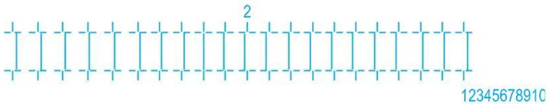
text_image
2 12345678910- Press the [+] key or [-] key on Operation panel to enter the number that you selected in Step 8.

flowchart
graph TD
    A["Power\n* Receiving Data"] --> B["Head Height\nHigh\nLow"]
    C["Error\n* Ink Low"] --> D["Output Mode\nTake Up @10\nAuto Cut -/-"]
    E["Nozzle Check\nPause\nCancel"] --> F["Nozzle Check\n+"]
    G["Enter\nCutting"] --> H["Cleaning Mode\nLong\nNormal\nShort"]
    I["Nozzle Check\nPause\nCancel"] --> J["Nozzle Check\n+"]
    K["Input"] --> L["+"]
    M["Input"] --> N["-"]
    O["Input"] --> P["+"]
    Q["Input"] --> R["-"]
    S["Input"] --> T["+"]
    U["Input"] --> V["-"]
    W["Input"] --> X["+"]
    Y["Input"] --> Z["-"]
- Press the [Enter] key on Operation panel.

flowchart
graph TD
    A["Power"] --> B["Receiving Data"]
    C["Error"] --> D["Ink Low"]
    E["Head Height"] --> F["High"]
    E --> G["Low"]
    H["Output Mode"] --> I["Take Up to 30"]
    H --> J["Auto Cut"]
    K["Cleaning Mode"] --> L["Long"]
    K --> M["Normal"]
    K --> N["Short"]
    O["Menu"] --> P["Nozzle Check"]
    O --> Q["Pause"]
    R["Enter"] --> S["Forward Test"]
    T["Backward Start"] --> U["+"]
    V["Forward End"] --> W["→"]
• Determines the setting.
- "Adj.2: Rough Pattern" is displayed on Operation panel.
3.6.1.3 Standard micro adjustment pattern
Perform micro adjustment when the degree of misalignment is small. Print micro adjustment pattern and register the set values.
-
Display the Standard Adjust Print menu on Operation panel in the same way as step 2 of 3.6.1.1 Standard confirmation pattern.
-
Press the [+] key or [-] key on Operation panel to select "Adj.3: Fine Pattern".
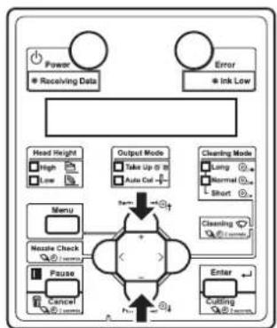
flowchart
graph TD
    A["Power"] --> B["Receiving Data"]
    C["Error"] --> D["Ink Low"]
    E["Head Height"] --> F["High"]
    E --> G["Low"]
    H["Menu"] --> I["Nzzle Check"]
    H --> J["Pause"]
    H --> K["Cancel"]
    L["Output Mode"] --> M["Take Up @ 0"]
    L --> N["Auto Cut +"]
    O["Cleaning Mode"] --> P["Lung"]
    O --> Q["Normal"]
    O --> R["Short"]
    S["Enter"] --> T["Coulding"]
    U["Start"] --> V["End"]
- Press the [Enter] key on Operation panel.
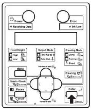
flowchart
graph TD
    A["Power"] --> B["Receiving Data"]
    C["Error"] --> D["Ink Low"]
    E["Head Height"] --> F["High"]
    E --> G["Low"]
    H["Output Mode"] --> I["Take Up @ 10"]
    H --> J["Auto Cut -"]
    K["Clearing Mode"] --> L["Long"]
    K --> M["Normal"]
    K --> N["Short"]
    O["Menu"] --> P["Nzzle Check"]
    O --> Q["Pause"]
    O --> R["Cancel"]
    S["Backward Load"] --> T["Forward Load"]
    U["Enter"] --> V["Forward Load"]
    W["External"] --> X["External"]
- For VJ-1638, "Warming Up Skip ->E" is displayed on Operation panel. (This is not displayed for VJ-1638W since it does not perform warming up.)
CAUTION
While "Warming Up" is displayed, do not touch Platen and Media guide. They become very hot and you could burn yourself.
NOTE
- You can start printing during warming up. 14.4.7 Starting printing during warming up (VJ-1638 only)
- An micro adjust print pattern is printed for both Head 1 and Head 2. (VJ-1638 starts printing after warming up is complete.)
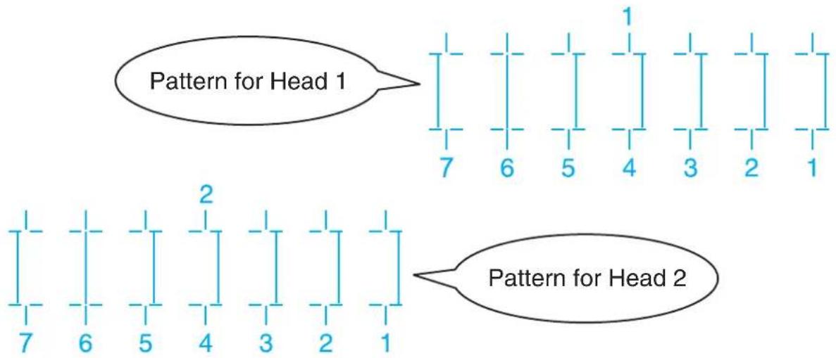
text_image
Pattern for Head 1 7 6 5 4 3 2 1 2 Pattern for Head 2 7 6 5 4 3 2 1- For the micro adjustment pattern, the same patterns will be printed on both sides and center of the media.
- For Head 1, check the print results on both sides and center of the media and select the number that looks most aligned between 1 and 7.
- 6 is selected in the next printing sample.
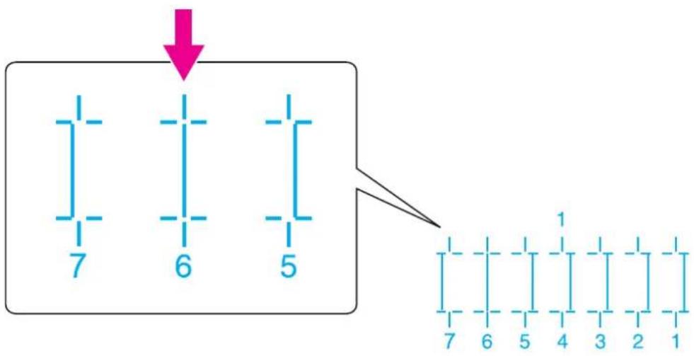
text_image
7 6 5 7 6 5 4 3 2 1NOTE
• 4 represents the current setting value.
- "Pattern*1: 4" (refer to the chart below for *) is displayed on Operation panel.
- The pattern name indicated by * differs depending on the set print mode. Print modes and corresponding pattern names are listed as follows.
| PrintMode Pattern name | |
| Quality 1, 2 C | |
| Quality 3, 4 B | |
| Graphics 1, 2 B | |
| Banner 1, 2 A | |
| Banner 3, 4 A |
NOTE
- Refer to the following for Print mode. 1首 5.1.1.1.1 Print Mode menu
- Press the [+] key or [-] key on Operation panel to enter the number that you selected in Step 4.
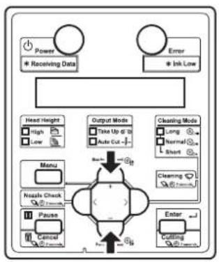
flowchart
graph TD
    A["Power"] --> B["Receiving Data"]
    C["Error"] --> D["Ink Low"]
    E["Head Height"] --> F["High"]
    E --> G["Low"]
    H["Menu"] --> I["Nzzle Check"]
    H --> J["Pause"]
    H --> K["Cancel"]
    L["Output Mode"] --> M["Take Up @ 18"]
    L --> N["Auto Cut -"]
    O["Cleaning Mode"] --> P["Long"]
    O --> Q["Normal"]
    O --> R["Short"]
    S["Clearing"] --> T["+"]
    U["Enter"] --> V["Cutting"]
    W["+"] --> X["+"]
    Y["+"] --> Z["-"]
NOTE
- When you press the [Cancel] key on Operation panel, the display returns to "Adj.3: Fine Pattern".
- Press the [Enter] key on Operation panel.

flowchart
graph TD
    A["Power"] --> B["* Receiving Date"]
    C["Error"] --> D["* Ink Low"]
    E["Head Height"] --> F["High"]
    E --> G["Low"]
    H["Output Mode"] --> I["Take Up @ 10"]
    H --> J["Auto Cut -"]
    K["Cleaning Mode"] --> L["Long"]
    K --> M["Normal"]
    K --> N["Short"]
    O["Menu"] --> P["Nozzle Check"]
    O --> Q["Pause"]
    O --> R["Cancel"]
    S["Backward test"] --> T["+"]
    U["Forward test"] --> V["-"]
    W["Enter"] --> X["Unknown"]
• Determines the setting.
- "Pattern*2: 4" is displayed next.
- For Head 2, check the print results on both sides and center of the media and select the number that looks most aligned between 1 and 7.

text_image
7 6 5 4 3 2 1- Press the [+] key or [-] key on Operation panel to enter the number that you selected in Step 8.

flowchart
graph TD
    A["Power"] --> B["Receiving Data"]
    C["Error"] --> D["Ink Low"]
    E["Head Height"] --> F["High"]
    E --> G["Low"]
    H["Menu"] --> I["Nzzle Check"]
    H --> J["Pause"]
    H --> K["Cancel"]
    L["Output Mode"] --> M["Take Up to 30"]
    L --> N["Auto Cut"]
    O["Cleaning Mode"] --> P["Long"]
    O --> Q["Normal"]
    O --> R["Short"]
    S["Enter"] --> T["Cutting"]
    U["Start"] --> V["Clearing"]
    W["End"] --> X["End"]
- Press the [Enter] key on Operation panel.

flowchart
graph TD
    A["Power"] --> B["Receiving Data"]
    C["Error"] --> D["Ink Low"]
    E["Head Height"] --> F["High"]
    E --> G["Low"]
    H["Menu"] --> I["Nzzle Check"]
    J["Pause"] --> K["Cancel"]
    L["Event"] --> M["Forward Event"]
    N["Output Mode"] --> O["Take Up @ 3"]
    N --> P["Auto Cut +"]
    Q["Cleaning Mode"] --> R["Long"]
    Q --> S["Normal"]
    Q --> T["Short"]
    U["Cleaning Mode"] --> V["Start Next"]
    W["Enter"] --> X["End"]
• Determines the setting.
- "Adj.3: Fine Pattern" is displayed on Operation panel.
3.6.2 Custom print quality adjustment
Perform adjustment for all patterns (A to F).
All print modes will be adjusted.
This menu consists of the following menus.
| Menu name Description | Reference | ||
| Custom confirmation pattern Print out | the confirmation patterns (A to F) and check the degree of misalignment. | 3.6.2.1 Custom confirmation pattern | |
| Custom rough adjustment pattern Perform this when the degree of misalignment is big. All confirmation patterns (A to F) will be adjusted. | 3.6.2.2 Custom rough adjustment pattern | ||
| Custom micro adjustment pattern | Adj. PatternALL Perform this when the degree of misalignment is small. All confirmation patterns (A to F) will be adjusted. | 3.6.2.3.1 Adj. PatternALL | |
| Individual Adj. pattern | Perform this when the degree of misalignment is small. One of the confirmation patterns (A to F) will be adjusted. | 3.6.2.3.2 Individual Adj. pattern | |
Follow the procedure below to perform adjustment.
- Print out the confirmation pattern and check the degree of misalignment.
13.6.2.1 Custom confirmation pattern
- Perform rough adjustment when the degree of misalignment is big.
3.6.2.2 Custom rough adjustment pattern
Perform micro adjustment when the degree of misalignment is small.
3.6.2.3 Custom micro adjustment pattern
NOTE
- Perform rough adjustment first when the degree of misalignment is difficult to determine.
- Print out the confirmation pattern again and check if the printer has been adjusted properly.
3.6.2.1 Custom confirmation pattern
- If it has not been adjusted yet, return to Step 2.
NOTE
- Perform micro adjustment if the printer is not fully adjusted after rough adjustment.
- In micro adjustment patterns, there are Adjust pattern ALL where all patterns will be adjusted and Individual Adj. pattern where the patterns A to F can be adjusted individually.
13.6.2.3.1 Adj. PatternALL
13.6.2.3.2 Individual Adj. pattern
3.6.2.1 Custom confirmation pattern
Using this menu, you can print out all of the confirmation patterns (A to F) and check the degree of misalignment.
- Turn ON the printer and load the roll media.
3.4.2 Setting Roll Media
- Display the Adjust Print menu on Operation panel.
a. Press the [Menu] key on Operation panel.
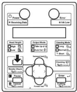
flowchart
graph TD
    A["Power"] --> B["Receiving Data"]
    C["Error"] --> D["Ink Low"]
    E["Head Height"] --> F["High"]
    E --> G["Low"]
    H["Output Mode"] --> I["Take Up @ 10"]
    H --> J["Auto Out +"]
    K["Cleaning Mode"] --> L["Long"]
    K --> M["Normal"]
    K --> N["Short"]
    O["Noodle Check"] --> P["+"]
    Q["Pause"] --> R["Cancel"]
    S["Enter"] --> T["Cutting"]
    U["Backward Test"] --> V["Forward Test"]
- "Menu1: Setup>" is displayed on Operation panel.
b. Press the [>] key on Operation panel to select "Menu1: User Type".
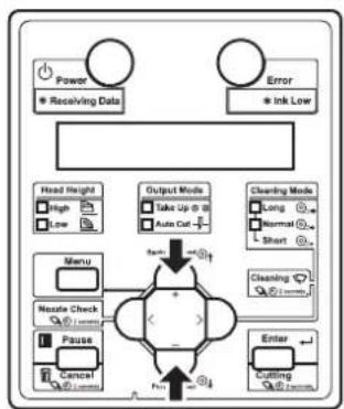
flowchart
graph TD
    A["Power"] --> B["Receiving Data"]
    C["Error"] --> D["Ink Low"]
    E["Head Height"] --> F["High"]
    E --> G["Low"]
    H["Menu"] --> I["Nestal Check"]
    H --> J["Pause"]
    H --> K["Cancel"]
    L["Output Mode"] --> M["Take Up @ 8"]
    L --> N["Auto Cut"]
    O["Cleaning Mode"] --> P["Long"]
    O --> Q["Normal"]
    O --> R["Short"]
    S["Enter"] --> T["Cutting"]
    S --> U["Cutting"]
    V["+/-"] --> W["+/-"]
    X["+/-"] --> Y["-"]
    Z["+/-"] --> AA["-"]
c. Press the [Enter] key on Operation panel.

flowchart
graph TD
    A["Power"] --> B["* Receiving Data"]
    C["Error"] --> D["* Ink Low"]
    E["Head Height"] --> F["High"]
    E --> G["Low"]
    H["Menu"] --> I["Rotator Check"]
    H --> J["Pause"]
    H --> K["Cancel"]
    L["Output Mode"] --> M["Take Up @ 28"]
    L --> N["Auto Cut"]
    O["Cleaning Mode"] --> P["Long"]
    O --> Q["Normal"]
    O --> R["Short"]
    S["Backward Event"] --> T["Forward Event"]
    U["Enter"] --> V["7-10mm"]
    W["+"] --> X["+"]
    Y["→"] --> Z["→"]
- "User: TypeXX" (XX is a number between 1 and 15) is displayed on Operation panel.
d. Press the [+] key or [-] key on Operation panel to select the user type setting.
e. Press the [Enter] key on Operation panel.
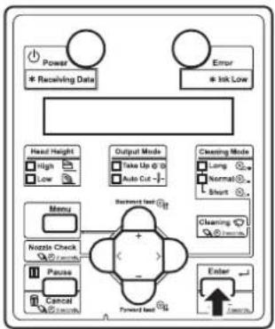
flowchart
graph TD
    A["Power"] --> B["* Receiving Date"]
    C["Error"] --> D["* Ink Low"]
    E["Head Height"] --> F["High"]
    E --> G["Low"]
    H["Menu"] --> I["Nozzle Check"]
    H --> J["Pause"]
    H --> K["Cancel"]
    L["Output Mode"] --> M["Take Up @ 1"]
    L --> N["Auto Cut -"]
    O["Clustering Mode"] --> P["Long"]
    O --> Q["Normal"]
    O --> R["Short"]
    S["Clustering Mode"] --> T["Short"]
    U["Forward Test"] --> V["+"]
    W["Enter"] --> X["1 w/w"]
    style A fill:#f9f,stroke:#333
    style C fill:#f9f,stroke:#333
    style E fill:#ccf,stroke:#333
    style L fill:#cfc,stroke:#333
    style O fill:#fcc,stroke:#333
    style U fill:#cff,stroke:#333
- "**1: Print Mode" is displayed on Operation panel.
f. Press the [+] key or [-] key on Operation panel to select "Menu2: Adjust Print".

flowchart
graph TD
    A["Power"] --> B["* Receiving Data"]
    C["Error"] --> D["* Ink Low"]
    E["Head Height"] --> F["High"]
    E --> G["Low"]
    H["Menu"] --> I["Nutle Check"]
    H --> J["Pause"]
    H --> K["Control"]
    L["Output Mode"] --> M["Take Up @ 10"]
    L --> N["Auto Cut -"]
    O["Cleaning Mode"] --> P["Long"]
    O --> Q["Normal"]
    O --> R["Short"]
    S["Cleaning Mode"] --> T["Short"]
    U["Enter"] --> V["Cutting"]
    W["Gate"] --> X["+"]
    Y["G1"] --> Z["-"]
g. Press the [>] key on Operation panel.
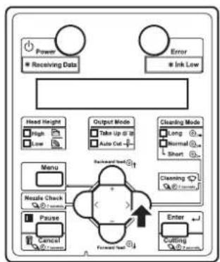
flowchart
graph TD
    A["Power"] --> B["Receiving Data"]
    C["Error"] --> D["Ink Low"]
    E["Head Height"] --> F["High"]
    E --> G["Low"]
    H["Output Mode"] --> I["Take Up to 30"]
    H --> J["Auto Cut"]
    K["Clearing Mode"] --> L["Long"]
    K --> M["Normal"]
    K --> N["Short"]
    O["Menu"] --> P["Nzzle Check"]
    O --> Q["Pause"]
    R["Enter"] --> S["Coulding"]
    R --> T["Forward Set"]
    U["Backward Shift"] --> V["+"]
    V --> W["Forward Set"]
    X["Feedback Mode"] --> Y["+"]
    Y --> Z["Forward Set"]
- "Adjust print1: Standard" is displayed on Operation panel.
h. Press the [+] key or [-] key on Operation panel to select "Adj Print2: Custom".
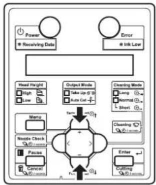
flowchart
graph TD
    A["Power<br>Receiving Data"] --> B["Error<br>Ink Low"]
    B --> C["Head Height<br>High<br>Low"]
    C --> D["Menu"]
    D --> E["Nestle Check<br>Pause<br>Cancel"]
    E --> F["Output Mode<br>Take Up @ 3<br>Auto Cut"]
    F --> G["Cleaning Mode<br>Long<br>Normal<br>Short"]
    G --> H["Enter<br>Cutting"]
    H --> I["Finish"]
    I --> J["End"]
i. Press the [Enter] key on Operation panel.
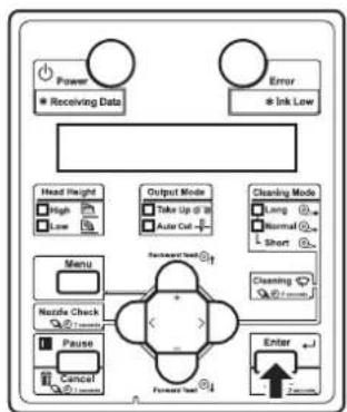
flowchart
graph TD
    A["Power"] --> B["Receiving Data"]
    C["Error"] --> D["Ink Low"]
    E["Head Height"] --> F["High"]
    E --> G["Low"]
    H["Menu"] --> I["Nzzle Check"]
    H --> J["Pause"]
    H --> K["Cancel"]
    L["Output Mode"] --> M["Take Up at 30"]
    L --> N["Auto Cat +"]
    O["Cleaning Mode"] --> P["Long"]
    O --> Q["Normal"]
    O --> R["Short"]
    S["Forward Test"] --> T["Enter"]
    U["2mm"] --> V["1mm"]
- "Adj.1: Confirm" is displayed on Operation panel.
- The display enters the Adjust Print menu. 5.1.1.1.2 Adjust Print menu
- Press the [Enter] key on Operation panel.

flowchart
graph TD
    A["Power"] --> B["Receiving Data"]
    C["Error"] --> D["Ink Low"]
    E["Head Height"] --> F["High"]
    E --> G["Low"]
    H["Menu"] --> I["Nazels Check"]
    H --> J["Pause"]
    H --> K["Control"]
    L["Output Mode"] --> M["Take Up @ 10"]
    L --> N["Auto Cut"]
    O["Cleaning Mode"] --> P["Long"]
    O --> Q["Normal"]
    O --> R["Short"]
    S["Backward Load"] --> T["Forward Load"]
    U["Enter"] --> V["Forward"]
    W["External Control"] --> X["External Control"]
- For VJ-1638, "Warming Up Skip ->E" is displayed on Operation panel. (This is not displayed for VJ-1638W since it does not perform warming up.)
CAUTION
While "Warming Up" is displayed, do not touch Platen and Media guide. They become very hot and you could burn yourself.
NOTE
- You can start printing during warming up. 14.4.7 Starting printing during warming up (VJ-1638 only)
- A confirmation pattern for print quality adjustment is printed. (VJ-1638 starts printing after warming up is complete.) - Six confirmation patterns of A to F will be printed.
NOTE
- Because this printer has 2 Print heads, 2 rows will be printed for each pattern.
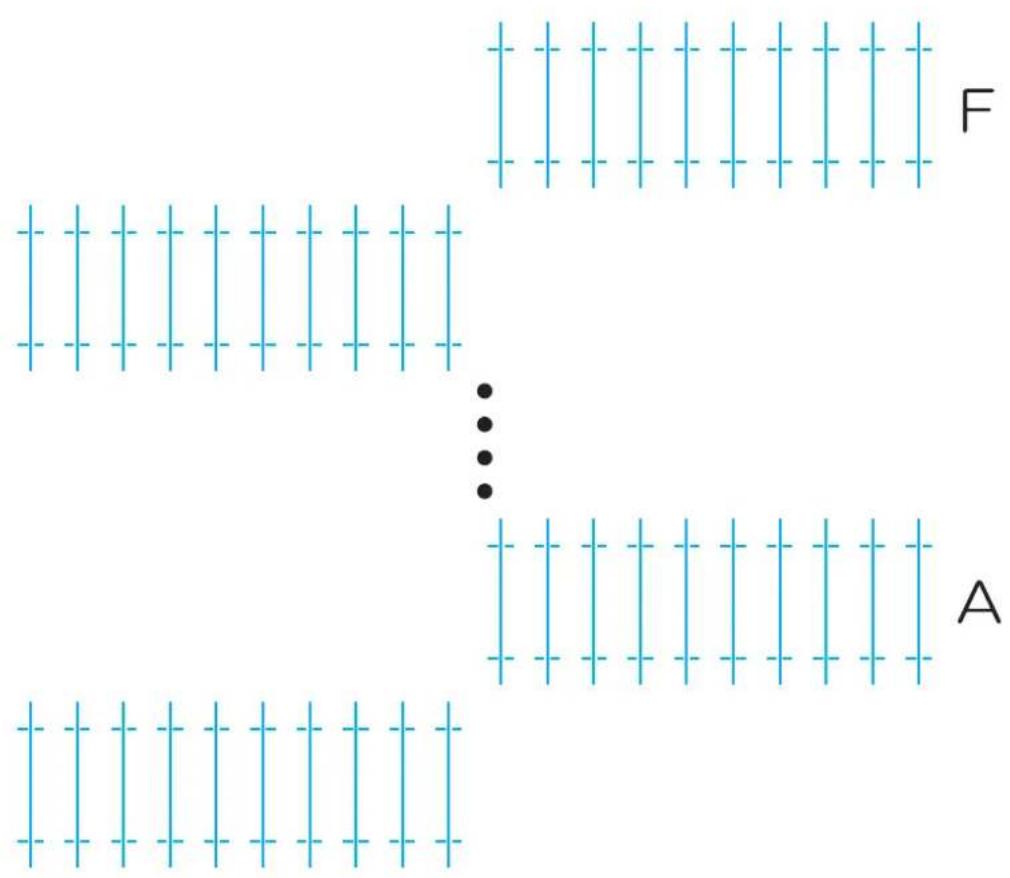
text_image
F A- After the confirmation pattern is printed, Operation panel returns to "Adj.1: Confirm".
- Confirm that the confirmation pattern printing result is as follows.
- Check each of the confirmation patterns A to F.

text_image
O X X Aa. When the printing result is OK;
You do not need perform print quality adjustment.
The procedure for print quality adjustment is complete.
b. When the printing result is NG;
You need to perform print quality adjustment.
- Perform rough adjustment when the degree of misalignment is big.
13.6.2.2 Custom rough adjustment pattern
- Perform micro adjustment when the degree of misalignment is small.
- When adjustment is required for all patterns (A to F): 3.6.2.3.1 Adj. PatternALL
- When adjustment is required for one of the patterns (A to F): 3.6.2.3.1 Individual Adj. pattern
3.6.2.2 Custom rough adjustment pattern
Perform rough adjustment when the degree of misalignment is big.
Print rough adjustment pattern and register the set values.
-
Display the Custom Adjust Print menu on Operation panel in the same way as Step 2 of 3.6.2.1 Custom confirmation pattern.
-
Press the [+] key or [-] key on Operation panel to select "Adj.2: Rough Pattern".
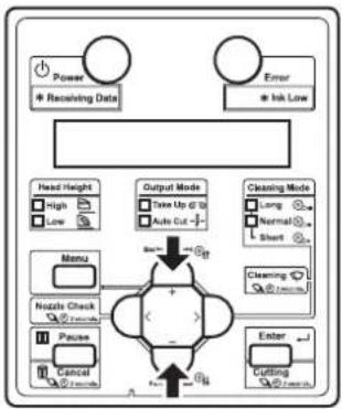
flowchart
graph TD
    A["Power"] --> B["Receiving Data"]
    C["Error"] --> D["Irk Low"]
    E["Head Height"] --> F["High"]
    E --> G["Low"]
    H["Menu"] --> I["Noise Check"]
    J["Pause"] --> K["Cancel"]
    L["Event"] --> M["Cutting"]
    N["Output Mode"] --> O["Take Up @ 12"]
    N --> P["Auto Cut"]
    Q["Cleaning Mode"] --> R["Long"]
    Q --> S["Normal"]
    Q --> T["Short"]
    U["Cleaning Mode"] --> V["Normal"]
    U --> W["Short"]
    X["Enter"] --> Y["Cutting"]
- Press the [Enter] key on Operation panel.

flowchart
graph TD
    A["Power"] --> B["* Receiving Data"]
    C["Error"] --> D["* Isk Low"]
    E["Head Height"] --> F["High"]
    E --> G["Low"]
    H["Output Mode"] --> I["Take Up @ 0"]
    H --> J["Auto Cut"]
    K["Cleaning Mode"] --> L["Long"]
    K --> M["Normal"]
    K --> N["Short"]
    O["Menu"] --> P["Nzzle Check"]
    O --> Q["Pause"]
    O --> R["Cancel"]
    S["Backward test"] --> T["Forward test"]
    U["Enter"] --> V["Return"]
    W["Input"] --> X["Feedback"]
- For VJ-1638, "Warming Up Skip ->E" is displayed on Operation panel.
(This is not displayed for VJ-1638W since it does not perform warming up.)

CAUTION
While "Warming Up" is displayed, do not touch Platen and Media guide. They become very hot and you could burn yourself.
NOTE
- You can start printing during warming up.
4.4.7 Starting printing during warming up (VJ-1638 only)
- Starts a rough adjustment pattern printing. (VJ-1638 starts printing after warming up is complete.)
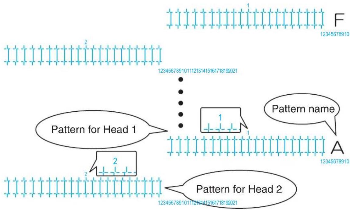
flowchart
graph TD
    A["Pattern for Head 1"] --> B["Pattern for Head 2"]
    B --> C["Pattern name"]
    C --> D["12345678910"]
    style A fill:#f9f,stroke:#333
    style B fill:#bbf,stroke:#333
    style C fill:#dfd,stroke:#333
    style D fill:#dfd,stroke:#333
- For the rough adjustment pattern, the same patterns will be printed on both sides and center of the media.
-
6 rough adjustment patterns (A to F) are printed. Enter the adjusted values for both Head 1 and Head 2.
-
For Head 1, check the print results on both sides and center of the media and select the number that looks most aligned between 1 and 21.
- "12" is selected in the following pattern A1.

text_image
1112131415 1 A 123456789NOTE
• 11 represents the current setting value.
-
"Pattern*1: 11" (refer to the chart below for *) is displayed on Operation panel.
-
Press the [+] key or [-] key on Operation panel to enter the number that you selected in Step 4.

flowchart
graph TD
    A["Power"] --> B["Receiving Data"]
    C["Error"] --> D["Irk Low"]
    E["Head Height"] --> F["High"]
    E --> G["Low"]
    H["Menu"] --> I["Nzzle Check"]
    H --> J["Pause"]
    H --> K["Control"]
    L["Output Mode"] --> M["Take Up @ 28"]
    L --> N["Auto Cut -"]
    O["Cleaning Mode"] --> P["Long"]
    O --> Q["Normal"]
    O --> R["Short"]
    S["Cleaning"] --> T["Enter"]
    U["Cutting"] --> V["Enter"]
    W["Input"] --> X["+"]
    Y["Input"] --> Z["-"]
NOTE
- When you press the [Cancel] key on Operation panel, the setting value is not entered and the display returns to "Adj.2: Rough Pattern".
- Press the [Enter] key on Operation panel.

flowchart
graph TD
    A["Power"] --> B["Receiving Data"]
    C["Error"] --> D["Ink Low"]
    E["Head Height"] --> F["High"]
    E --> G["Low"]
    H["Output Mode"] --> I["Take Up @ 10"]
    H --> J["Auto Out"]
    K["Cleaning Mode"] --> L["Long"]
    K --> M["Normal"]
    K --> N["Short"]
    O["Menu"] --> P["Nzzle Check"]
    O --> Q["Pause"]
    O --> R["Cancel"]
    S["Forward Test"] --> T["Enter"]
    U["Forward Test"] --> V["7.5mm"]
• Determines the setting.
- "Pattern*2: 11" is displayed next.
- For Head 2, check the print results on both sides and center of the media and select the number that looks most aligned between 1 and 21.
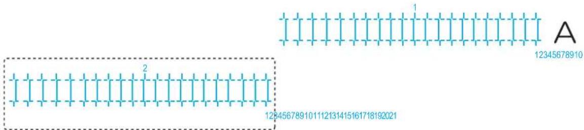
text_image
1 2 A 12345678910 128456789101112131415161718192021- Press the [+] key or [-] key on Operation panel to enter the number that you selected in Step 8.
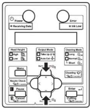
flowchart
graph TD
    A["Power"] --> B["Receiving Data"]
    C["Error"] --> D["Ink Low"]
    E["Head Height"] --> F["High"]
    E --> G["Low"]
    H["Menu"] --> I["Nzzle Check"]
    H --> J["Pause"]
    H --> K["Cancel"]
    L["Output Mode"] --> M["Take Up @ 10"]
    L --> N["Auto Cut +"]
    O["Cleaning Mode"] --> P["Long"]
    O --> Q["Normal"]
    O --> R["Short"]
    S["Enter"] --> T["Cutting @ 100%"]
    U["Check"] --> V["+"]
    W["+"] --> X["-"]
    Y["+"] --> Z["-"]
    style A fill:#fff,stroke:#333
    style C fill:#fff,stroke:#333
    style E fill:#fff,stroke:#333
    style L fill:#fff,stroke:#333
    style O fill:#fff,stroke:#333
    style S fill:#fff,stroke:#333
    style U fill:#fff,stroke:#333
    style V fill:#fff,stroke:#333
- Press the [Enter] key on Operation panel.

flowchart
graph TD
    A["Power"] --> B["* Receiving Data"]
    C["Error"] --> D["* Ink Low"]
    E["Head Height"] --> F["High"]
    E --> G["Low"]
    H["Menu"] --> I["Nazels Check"]
    H --> J["Pause"]
    H --> K["Control"]
    L["Output Mode"] --> M["Take Up @ 10"]
    L --> N["Auto Cut -"]
    O["Cleaning Mode"] --> P["Long"]
    O --> Q["Normal"]
    O --> R["Short"]
    S["Forward Load"] --> T["Backward Load"]
    U["Enter"] --> V["Forward Load"]
    W["External Control"] --> X["External Signal"]
• Determines the setting.
- Enter the values for patterns B to F in the same way.
- Press the [Enter] key to set the value.
- Once all set values have been entered, press the [Enter] key to register the set values of patterns A to F.
- "Adj.2: Rough Pattern" is displayed on Operation panel.
3.6.2.3 Custom micro adjustment pattern
Perform micro adjustment when the degree of misalignment is small. This menu consists of the following menus.
| Menu name Description | Reference | ||
| Custom micro adjustment pattern | Adj. PatternALL All confirmation patterns (A to F) will be adjusted. | 3.6.2.3.1 Adj. PatternALL | |
| Individual Adj. pattern | One of the confirmation patterns (A to F) will be adjusted. | 3.6.2.3.2 Individual Adj. pattern | |
3.6.2.3.1 Adj. PatternALL
Print micro adjustment pattern ALL and register the set values.
-
Display the Custom Adjust Print menu on Operation panel in the same way as Step 2 of 3.6.2.1 Custom confirmation pattern.
-
Press the [+] key or [-] key on Operation panel to select "Adj.3: Fine Pattern".

flowchart
graph TD
    A["Power"] --> B["Receiving Data"]
    C["Error"] --> D["Ink Low"]
    E["Head Height"] --> F["High"]
    E --> G["Low"]
    H["Menu"] --> I["Nzzle Check"]
    H --> J["Pause"]
    H --> K["Cancel"]
    L["Output Mode"] --> M["Take Up or 10"]
    L --> N["Auto Cut"]
    O["Cleaning Mode"] --> P["Long"]
    O --> Q["Normal"]
    O --> R["Short"]
    S["Clustering"] --> T["Enter"]
    U["Cutting"] --> V["Enter"]
    W["Enter"] --> X["Enter"]
    Y["Enter"] --> Z["Enter"]
    style A fill:#f9f,stroke:#333
    style C fill:#f9f,stroke:#333
    style E fill:#ccf,stroke:#333
    style L fill:#cfc,stroke:#333
    style O fill:#fcc,stroke:#333
    style U fill:#cff,stroke:#333
    style V fill:#ffc,stroke:#333
    style W fill:#fcc,stroke:#333
- Press the [Enter] key on Operation panel.

flowchart
graph TD
    A["Power"] --> B["Receiving Data"]
    C["Error"] --> D["Ink Low"]
    E["Head Height"] --> F["High"]
    E --> G["Low"]
    H["Output Mode"] --> I["Take Up @ 10"]
    H --> J["Auto Cut +"]
    K["Cleaning Mode"] --> L["Long"]
    K --> M["Normal"]
    K --> N["Short"]
    O["Menu"] --> P["Backward test"]
    Q["Nestle Check"] --> R["+"]
    S["Pause"] --> T["-"]
    U["Cancel"] --> V["Forward test"]
    W["Enter"] --> X["Forward test"]
- For VJ-1638, "Warming Up Skip ->E" is displayed on Operation panel. (This is not displayed for VJ-1638W since it does not perform warming up.)
CAUTION
While "Warming Up" is displayed, do not touch Platen and Media guide. They become very hot and you could burn yourself.
NOTE
- You can start printing during warming up. 4.4.7 Starting printing during warming up (VJ-1638 only)
- An adjust print pattern is printed.
For Adjust print pattern printing, 6 adjust print patterns (A to F) are printed. Enter the adjusted values for both Head 1 and Head 2.
(VJ-1638 starts printing after warming up is complete.)
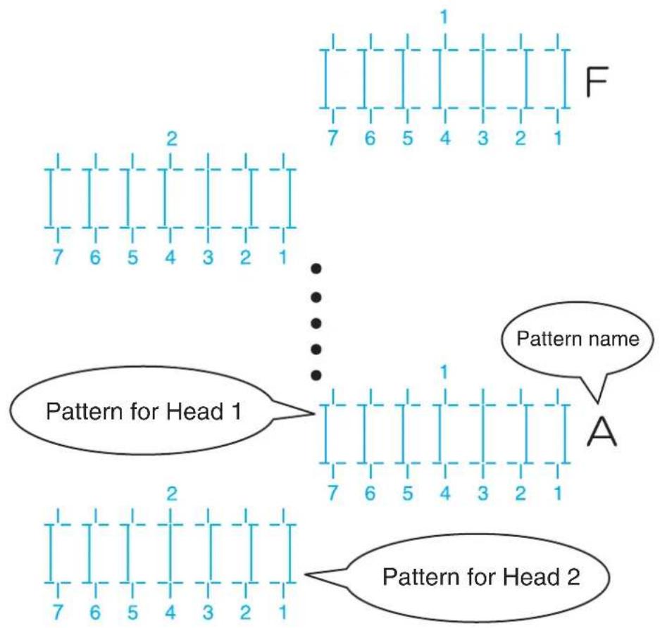
text_image
Pattern for Head 1 Pattern for Head 2 Pattern name A 7 6 5 4 3 2 1 7 6 5 4 3 2 1- For the Adjust print pattern, the same patterns will be printed repeatedly on both sides and center of the media.
- For Head 1, check the print results on both sides and center of the media and select the number that looks most aligned between 1 and 7.
- "3" is selected in the following pattern A.
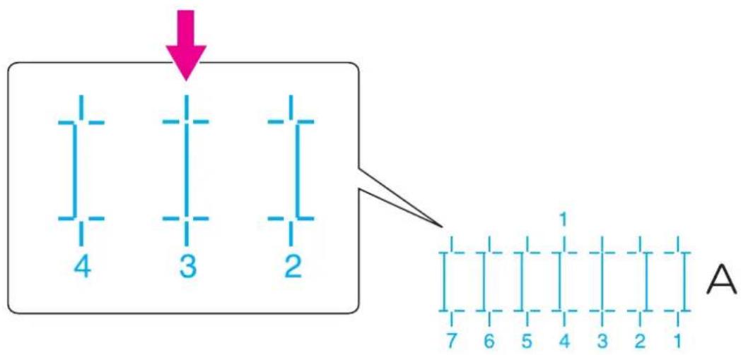
flowchart
graph TD
    A["Vertical Bars 4"] --> B["Vertical Bars 3"]
    A --> C["Vertical Bars 2"]
    D["Grid 7"] --> E["Grid 6"] --> F["Grid 5"] --> G["Grid 4"] --> H["Grid 3"] --> I["Grid 2"] --> J["Grid 1"]
NOTE
• 4 represents the current setting value.
-
"Pattern*1: 4" (refer to the chart below for *) is displayed on Operation panel.
-
Press the [+] key or [-] key on Operation panel to enter the number that you selected in Step 4.

flowchart
graph TD
    A["Power"] --> B["Receiving Data"]
    C["Error"] --> D["Ink Low"]
    E["Menu"] --> F["Nzzle Check"]
    G["Pause"] --> H["Cancel"]
    I["Enter"] --> J["Cutting"]
    K["Head Height"] --> L["High"]
    K --> M["Low"]
    N["Output Mode"] --> O["Take Up at 0"]
    N --> P["Auto Cut"]
    Q["Cleaning Mode"] --> R["Long"]
    Q --> S["Normal"]
    Q --> T["Short"]
    U["No Input"] --> V["+"]
    W["No Input"] --> X["-"]
    Y["No Input"] --> Z["+"]
    AA["No Input"] --> AB["-"]
NOTE
- When you press the [Cancel] key on Operation panel, the display returns to "Adj.3: Fine Ptn. ALL".
- Press the [Enter] key on Operation panel.

flowchart
graph TD
    A["Power"] --> B["* Receiving Data"]
    C["Error"] --> D["* Ink Low"]
    E["Head Height"] --> F["High"]
    E --> G["Low"]
    H["Menu"] --> I["Nzzle Check"]
    H --> J["Pause"]
    H --> K["Control"]
    L["Output Mode"] --> M["Take Up @ 10"]
    L --> N["Auto Cut -"]
    O["Cleaning Mode"] --> P["Long"]
    O --> Q["Normal"]
    O --> R["Short"]
    S["Forward Load"] --> T["Backward Load"]
    U["Enter"] --> V["Forward Load"]
• Determines the setting.
- "Pattern*2: 4" is displayed next.
- For Head 2, check the print results on both sides and center of the media and select the number that looks most aligned between 1 and 7.

text_image
A 1 7 6 5 4 3 2 1 2 7 6 5 4 3 2 1- Press the [+] key or [-] key on Operation panel to enter the number that you selected in Step 8.
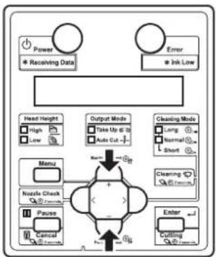
flowchart
graph TD
    A["Power"] --> B["Receiving Data"]
    C["Error"] --> D["Ink Low"]
    E["Menu"] --> F["Nzzle Check"]
    G["Pause"] --> H["Cancel"]
    I["Event"] --> J["Cutting"]
    K["Head Height"] --> L["High"]
    K --> M["Low"]
    N["Output Mode"] --> O["Take Up @ 10"]
    N --> P["Auto Cut -"]
    Q["Cleaning Mode"] --> R["Long"]
    Q --> S["Normal"]
    Q --> T["Short"]
    U["Cleaning Mode"] --> V["Short"]
    W["Enter"] --> X["Cutting"]
- Press the [Enter] key on Operation panel.
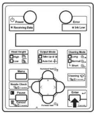
flowchart
graph TD
    A["Power"] --> B["Receiving Data"]
    C["Error"] --> D["Ink Low"]
    E["Head Height"] --> F["High"]
    E --> G["Low"]
    H["Output Mode"] --> I["Take Up @ 18"]
    H --> J["Auto Out"]
    K["Cleaning Mode"] --> L["Long"]
    K --> M["Normal"]
    K --> N["Short"]
    O["Menu"] --> P["Nozzle Check"]
    O --> Q["Pause"]
    O --> R["Cancel"]
    S["Forward Test"] --> T["Reversed Test"]
    U["Enter"] --> V["Forward Test"]
    W["70%"] --> X["70%"]
• Determines the setting.
- Enter the values for patterns B to F in the same way.
- Press the [Enter] key to set the value.
- Once all set values have been entered, press the [Enter] key to register the set values of patterns A to F.
- "Adj.3: Fine Ptn. ALL" is displayed on Operation panel.
3.6.2.3.2 Individual Adj. pattern
Print one adjustment pattern from A to F and register the set value.
The following describes how to adjust pattern A only.
-
Display the Custom Adjust Print menu on Operation panel in the same way as Step 2 of 3.6.2.1 Custom confirmation pattern.
-
Press the [+] key or [-] key on Operation panel to select "Adj4: Fine PatternA".

flowchart
graph TD
    A["Power"] --> B["Receiving Data"]
    C["Error"] --> D["Ink Low"]
    E["Head Height"] --> F["High"]
    E --> G["Low"]
    H["Menu"] --> I["Nzzle Check"]
    J["Pause"] --> K["Cancel"]
    L["Cutting"] --> M["Enter"]
    N["Take Up @ 10"] --> O["Auto Cut"]
    P["Normal"] --> Q["Short"]
    R["Cleaning Mode"] --> S["Long"]
    R --> T["Normal"]
    R --> U["Short"]
    V["+/-"] --> W["+/-"]
    X["+/-"] --> Y["+/-"]
    Z["+/-"] --> AA["+/-"]
- Press the [Enter] key on Operation panel.

flowchart
graph TD
    A["Power"] --> B["Receiving Data"]
    C["Error"] --> D["Ink Low"]
    E["Head Height"] --> F["High"]
    E --> G["Low"]
    H["Output Mode"] --> I["Take Up @ 10"]
    H --> J["Auto Cut -"]
    K["Cleaning Mode"] --> L["Long"]
    K --> M["Normal"]
    K --> N["Short"]
    O["Menu"] --> P["Nozzle Check"]
    O --> Q["Pause"]
    O --> R["Cancel"]
    S["Backward Test"] --> T["+"]
    U["Forward Test"] --> V["-"]
    W["Enter"] --> X["Forward"]
    style S fill:#f9f,stroke:#333
    style U fill:#f9f,stroke:#333
- For VJ-1638, "Warming Up Skip ->E" is displayed on Operation panel. (This is not displayed for VJ-1638W since it does not perform warming up.)
CAUTION
While "Warming Up" is displayed, do not touch Platen and Media guide. They become very hot and you could burn yourself.
NOTE
- You can start printing during warming up. 4.4.7 Starting printing during warming up (VJ-1638 only)
- An micro adjust print pattern is printed for both Head 1 and Head 2. (VJ-1638 starts printing after warming up is complete.)

text_image
Pattern for Head 1 Pattern name A 7 6 5 4 3 2 1 2 7 6 5 4 3 2 1 Pattern for Head 2- For the Adjust print pattern, the same patterns will be printed repeatedly on both sides and center of the media.
- For Head 1, check the print results on both sides and center of the media and select the number that looks most aligned between 1 and 7.
- "6" is selected in the next printing sample.
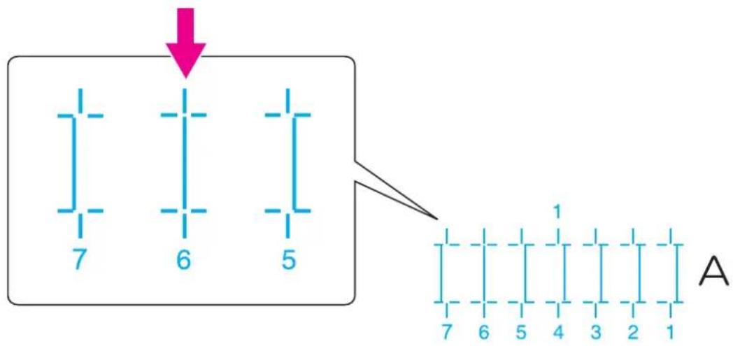
text_image
7 6 5 A 1 7 6 5 4 3 2 1NOTE
• 4 represents the current setting value.
-
"PatternA1: 4" is displayed on Operation panel.
-
Press the [+] key or [-] key on Operation panel to enter the number that you selected in Step 4.
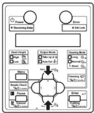
flowchart
graph TD
    A["Power"] --> B["Receiving Data"]
    C["Error"] --> D["Ink/Low"]
    E["Head Height"] --> F["High Low"]
    G["Menu"] --> H["Noise Check"]
    I["Pause"] --> J["Cancel"]
    K["Output Mode"] --> L["Take Up to 10"]
    K --> M["Auto Cut"]
    N["Cleaning Mode"] --> O["Long Normal Short"]
    P["Enter"] --> Q["Cutting"]
    R["+/-"] --> S["+/-"]
    T["+/-"] --> U["-/-"]
    V["+/-"] --> W["-/-"]
    X["+/-"] --> Y["+/-"]
    Z["+/-"] --> AA["-/-"]
NOTE
- When you press the [Cancel] key on Operation panel, the display returns to "Adj4: Fine PatternA".
- Press the [Enter] key on Operation panel.

flowchart
graph TD
    A["Power"] --> B["* Receiving Data"]
    C["Error"] --> D["* Ink Low"]
    E["Head Height"] --> F["High"]
    E --> G["Low"]
    H["Menu"] --> I["Nzzle Check"]
    H --> J["Pause"]
    H --> K["Control"]
    L["Output Mode"] --> M["Take Up @ 10"]
    L --> N["Auto Cut -"]
    O["Cleaning Mode"] --> P["Long"]
    O --> Q["Normal"]
    O --> R["Short"]
    S["Forward Load"] --> T["Backward Load"]
    U["Enter"] --> V["Forward Load"]
    W["External Control"] --> X["External Control"]
• Determines the setting.
- "PatternA2: 4" is displayed next.
- For Head 2, check the print results on both sides and center of the media and select the number that looks most aligned between 1 and 7.

text_image
A 7 6 5 4 3 2 1 2- Press the [+] key or [-] key on Operation panel to enter the number that you selected in Step 8.

flowchart
graph TD
    A["Power"] --> B["* Receiving Data"]
    C["Error"] --> D["* Ink Low"]
    E["Head Height"] --> F["High"]
    E --> G["Low"]
    H["Menu"] --> I["Nutle Check"]
    H --> J["Pause"]
    H --> K["Control"]
    L["Output Mode"] --> M["Take Up @ 12"]
    L --> N["Auto Cut -"]
    O["Cleaning Mode"] --> P["Long"]
    O --> Q["Normal"]
    O --> R["Short"]
    S["Cleaning Mode"] --> T["Start"]
    U["Enter"] --> V["Cutting"]
    W["Input"] --> X["+"]
    Y["Feedback"] --> Z["-"]
- Press the [Enter] key on Operation panel.
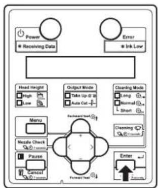
flowchart
graph TD
    A["Power"] --> B["Receiving Data"]
    C["Error"] --> D["Ink Low"]
    E["Head Height"] --> F["High"]
    E --> G["Low"]
    H["Output Mode"] --> I["Take Up to 30"]
    H --> J["Auto Cut"]
    K["Cleaning Mode"] --> L["Long"]
    K --> M["Normal"]
    K --> N["Short"]
    O["Menu"] --> P["Nestle Check"]
    O --> Q["Pause"]
    R["Enter"] --> S["7 mm"]
    T["Backward Start"] --> U["Forward Start"]
• Determines the setting.
- "Adj4: Fine PatternA" is displayed on Operation panel.
3.7 Connecting the printer to PC
This section explains how to connect the printer and a PC.
3.7.1 System requirements
The system requirements for this printer and the recommended software server RIP (option) are as follows.
| Operating system | Windows 2000 Professional, Windows XP Professional, Windows Vista Business, Windows 7 Professional, Windows Server 2003, Windows Server 2008 |
| CPU Pentium III processor 1 GHz or more | |
| Memory (RAM) 512 MB or more | |
| Hard disk free space 10 GB or more | |
NOTE
- The required memory varies depending on the application software or the print data type.
• A large hard disk and memory are recommended.
3.7.2 Preparing cables
The printer is equipped with a network interface for connecting with a PC. You need a network interface cable to connect a PC with this printer. Prepare the cable depending on the PC that it will be connected to.
TIP
- About connecting a network interface cable, refer to "3.7.3 Connecting a network interface cable".
- For the recommended cable specifications, refer to "8.2 Interface specification".
3.7.3 Connecting a network interface cable
This section explains how to connect a network interface cable.
Follow the procedure below to connect this printer to your PC.
NOTE
- When connecting the printer and computer via the hub, use a straight cable.
-
When connecting the printer and computer Peer-to-Peer, use a crossover cable.
-
Turn OFF both the printer and PC.
-
Insert the network interface cable into the network interface connector located on the back of the printer.

natural_image
Technical line drawing of a mechanical device with an inset showing a close-up of a component labeled 1 and 2 (no text or symbols present)| No. | Name |
| 1 | Network interface cable |
| 2 | Network interface cable connector |
- Connect the other connector of the network interface cable to your PC.
TIP
- About connecting to your PC, refer to the operation manual included with the PC.
- For network setting of the printer, refer to the following.
5.1.23 IP Address menu
5.1.24 Subnet Mask menu
5.1.25 Gateway menu
4 Handling the printer
This chapter explains how to handle the printer.
4.1 Print flow chart
The following flow chart illustrates the procedure to perform printing with the printer. Refer to each section as required.
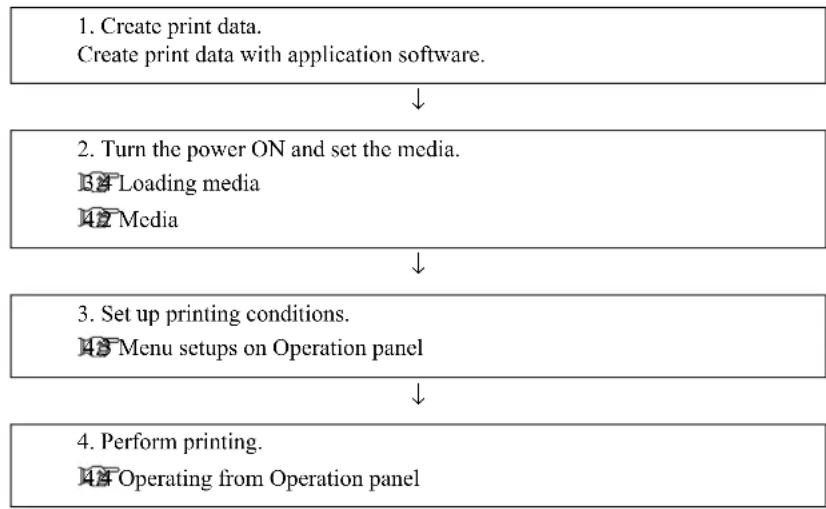
flowchart
graph TD
    A["1. Create print data.<br>Create print data with application software."] --> B["2. Turn the power ON and set the media.<br>Loading media<br>Media"]
    B --> C["3. Set up printing conditions.<br>Menu setups on Operation panel"]
    C --> D["4. Perform printing.<br>Operating from Operation panel"]
Since VJ-1638 is equipped with Heaters, strictly comply with the following Warnings and Cautions.

WARNING
- Do not place any combustible materials on Platen while the heater is working. There may be a risk of fire.
- Do not spill flammable liquid on Platen. It may cause a fire.

CAUTION
- Do not touch Media guide while printing.
Media guide becomes very hot and you could burn yourself. - Do not touch Media feed slot, Platen, and Media guide while Heater is working. Media feed slot, Platen, and Media guide become very hot and you could burn yourself.
- Ventilate the workplace. Not doing so may cause nausea or a fire hazzard.
NOTE
- Do not open Front cover and Maintenance cover during printing.
If the above covers are opened, printing will be interrupted.
Printing restarts once Covers are closed. However, you are not guaranteed to have high print quality.
4.2 Media
This section explains details of available media for this printer.
4.2.1 Media type
The type and quality of media greatly influence the print result.
Fully understand the following and use the media that matches the intended use.
The following media is recommended and available for this printer.
Select the appropriate media according to the intended use.
NOTE
- For details of the recommended media, contact your local MUTOH dealer.
- If failures or malfunctions of the printer occur by using the media other than the recommended media:
- The printer will not be covered by the warranty and repair expenses will be covered by the customer.
- For details, refer to the following.
6 Maintenance
7 Troubleshooting - To request a repair, contact your local MUTOH dealer.
TIP
- When printing on media that is not recommended,
- Refer to the media manual or ask where you purchased the media for information on media types and appropriate settings for this printer.
- Set the print quality according to "5.1.1 User Type menu".
4.2.2 Cautions on handling media
Note the following points when handling the media.
NOTE
- Use recommended media under an appropriate environment.
The appropriate temperature and humidity for printing are as follows.
| TemperatureHumidity | ||
| Guaranteed range of printing accuracy | 22°C to 30°C | 40% to 60% |
| Within 2°C per hour | Within 5 % per hourCl | |
- Do not use media which is creased, cut, torn, or curled.
- The size of media can change according to changes in humidity in the printing environment.
Before using media, leave media for 30 minutes in the printing environment to adapt it to the environment.
Performing printing without adapting media to the printing environment may cause media jams due to gaps or wrinkles in the media.
Print quality is also affected.
- When using the printer in a low-humidity environment, the cut media may stuck and may not come down. In such a case, open Front cover after the media is cut and remove the media.
- Do not touch the print side.
Moisture and oil on your hands may affect the print quality.
- Do not leave media set in the printer for a long time.
Some media has a tendency to bend, causing media jams and degradation of print quality.
Avoid using such media especially in winter, in dry conditions, and when printing formal documents.
- Do not discard the individual box and bag. Use them for storing media.
4.2.3 Precaution on storing media
Note the following points on storing media.
NOTE
- Avoid high temperature, high humidity, and direct sunlight when storing media.
- After removing the unused roll media from Feed unit, wind it properly. Then wrap it with an individual bag and store it in an individual box.
- Keep the media dry.
4.2.4 Printable area
The printable area of this printer is as follows.
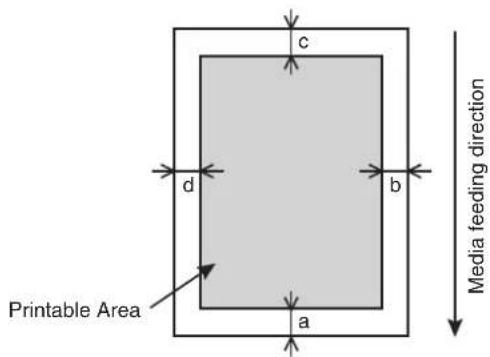
text_image
c d b a Printable Area Media feeding directiona=5mm *1 b=5mm to 25mm c=5mm d=5mm to 25mm
*1 The value of "a" will be 15 mm in the following cases:
- Immediately after media initialization
- When feeding the media by using the [Backward] key
The value of "a" will be 40mm in the following cases: - When Media Initial menu is set to "Top&Width"
- After cutting the media
4.2.5 Head height adjustment
Printing with high printing rate or using strongly-curved media can cause Print heads to rub the media. Changing the distance from Print head surface to the media (head height) may allow you to prevent Head from rubbing the media.
Head height can be changed to three levels.
Follow the procedure below to change the head height.
TIP
• The illustrations used in this section are those of VJ-1638.
4.2.5.1 When setting the head height to Mid
NOTE
- Do not open Front cover and change the head height during printing. If the head height is changed, the alignment will be changed and high print quality will not be guaranteed.
- Open Front cover.
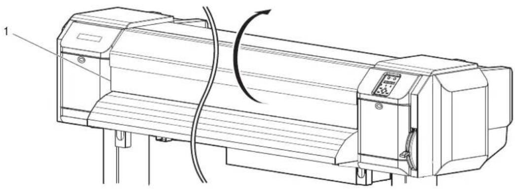
natural_image
Technical line drawing of a mechanical device with a curved arrow indicating rotation or motion (no text or symbols present)| No. | Name |
| 1 | Front cover |
- Change the head height by moving Head height adjustment lever (orange).

text_image
1 High Low Mid ORIGIN| No. | Name |
| 1 | Head height adjustment lever |
• High lamp on Operation panel lights up in green.
- Low lamp on Operation panel lights up in green.
3. Close Front cover.
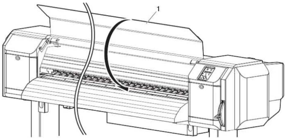
natural_image
Technical line drawing of a printer with paper feed and control panel (no text or symbols)| No. | Name |
| 1 | Front cover |
4.2.5.2 When setting the head height to High
NOTE
- If Head height adjustment lever is raised, high print quality is not guaranteed.
- Do not open Front cover and change the head height during printing. If the head height is changed, the alignment will be changed and high print quality will not be guaranteed.
1. Open Front cover.

natural_image
Technical line drawing of a mechanical device with a rotating shaft and control panel (no text or symbols)| No. | Name |
| 1 Front cover | |
- Change the head height by moving Head height adjustment lever (orange).
NOTE
- Do not raise Head height adjustment lever higher than the following position. Doing so may damage the printer.
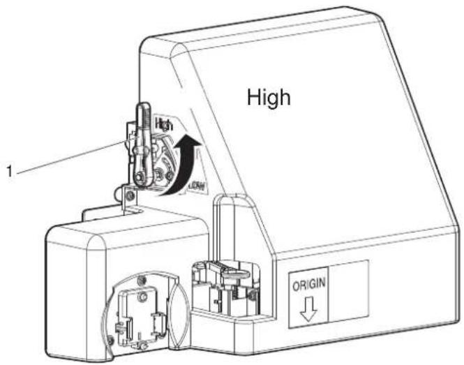
text_image
High 1 High LOW ORIGIN| No. | Name |
| 1 | Head height adjustment lever |
• High lamp on Operation panel lights up in green.
- Close Front cover.
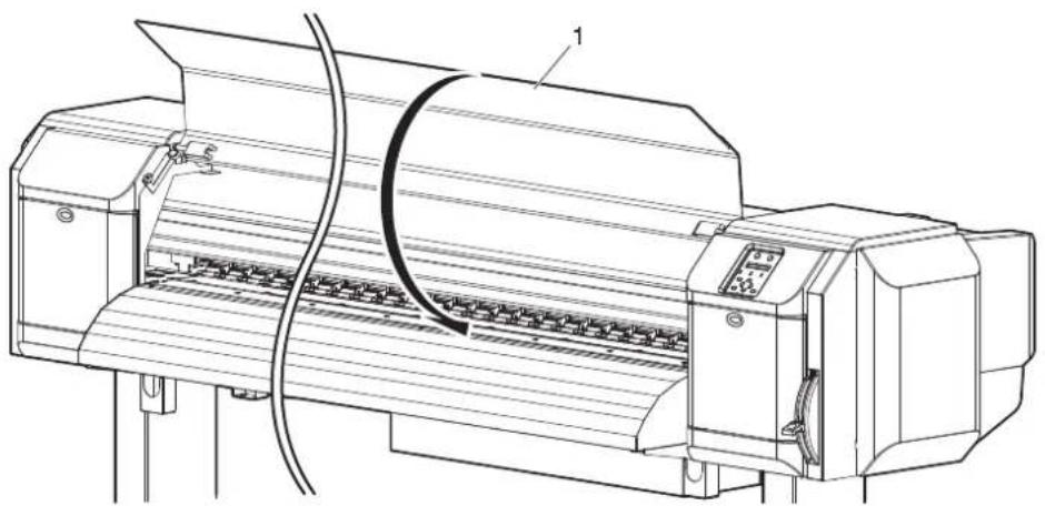
natural_image
Technical line drawing of a printer with paper feed and paperclip, no text or symbols present| No. | Name |
| 1 | Front cover |
4.2.5.3 When setting the head height to Low
NOTE
- Do not open Front cover and change the head height during printing. If the head height is changed, the alignment will be changed and high print quality will not be guaranteed.
- Open Front cover.
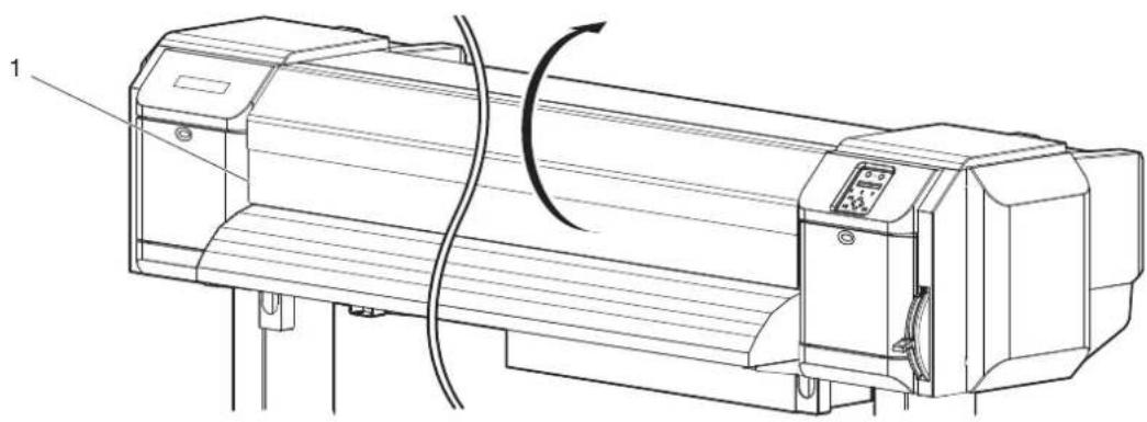
natural_image
Technical line drawing of a mechanical device with a rotating shaft and control panel (no text or symbols)| No. | Name |
| 1 | Front cover |
- Change the head height by moving Head height adjustment lever (orange).

text_image
High Mild Low 1 ORIGIN| No. | Name |
| 1 | Head height adjustment lever |
- Low lamp on Operation panel lights up in green.
- Close Front cover.

natural_image
Technical line drawing of a printer with paper feed and paperclip, showing internal structure (no text or symbols)| No. | Name |
| 1 | Front cover |
4.2.6 Media feed compensation
This section explains the Media feed compensation.
The feeding length depends on the media type. The following or similar results may be seen in prints.
- Printed images overlap.
- White lines are printed over images.
The accuracy of media feeding may be improved with the following methods.
- Adjust the media feed compensation value.
4.2.6.1 Procedure for the media feed compensation value
- Fix the media firmly.
4.2.6.2 How to fix the media firmly
4.2.6.1 Procedure for the media feed compensation value
- Display the Dist.Adj menu on Operation panel.
a. Press the [Menu] key on Operation panel.
- "Menu1: Setup>" is displayed on Operation panel.
- The operation panel shifts to the Setup menu display.
b. Press the [>] key on Operation panel.
- "Set1: User Type" is displayed on Operation panel.
c. Press the [Enter] key on Operation panel.
- "User: TypeXX" (XX is a number between 1 and 15) is displayed on Operation panel.
d. Press the [+] key or [-] key on Operation panel to select the user type to use.
e. Press the [Enter] key on Operation panel.
- "**>1: Print Mode" is displayed on Operation panel.
TIP
- The selected user type (Type 1 to 15) is displayed in "**".
5.1.1 User Type menu
f. Press the [+] key or [-] key on Operation panel to select " **>3 : PF Adjust".
g. Press the [>] key on Operation panel.
- "PF1: Initial Print" is displayed on Operation panel.
• Proceed to Dist.Adj menu.
5.1.1.1.3 Media feed compensation
2. Performs Initial Adjust Print.
a. Press the [Enter] key on Operation panel.
- "Feed Length: 250 mm" is displayed on Operation panel.
TIP
- The length of media that is fed (feeding length) for initial adjustment printing is normally set at 250 mm.
- If you increase the feeding length, the accuracy of the Media feed compensation improves. To change the feeding length, press the [+] key or [-] key on Operation panel and change the set value.
b. Press the [Enter] key on Operation panel.
- "Printing" is displayed on Operation panel.
- Starts initial adjustment printing.
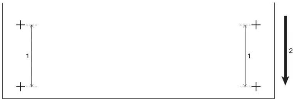
text_image
1 1 2| No. | Name |
| 1 | FeedLength |
| 2 | Media feeding direction |
- When the initial adjustment printing is complete, the printer enters Normal.
c. After the initial adjustment printing, cut the media.
4.4.3 Cutting media
- Measure the distance between the two pluses (+) in the initial adjustment print using a ruler.
- Sets up Initial Adjust Change.
a. Press the [+] key or [-] key on Operation panel to select "PF2: Initial Change".
b. Press the [Enter] key on Operation panel.
- "Init.: 250.0/250 mm" is displayed on Operation panel.
c. Press the [+] key or [-] key on Operation panel and enter the measured value in Step 3.
d. Press the [Enter] key on Operation panel.
• The initial adjustment value is saved.
- "PF2: Initial Change" is displayed on Operation panel.
- Performs Confirm Print.
a. Press the [+] key or [-] key on Operation panel to select "PF3: Confirm Print".
b. Press the [Enter] key on Operation panel.
- "Feed Length: 250 mm" is displayed on Operation panel.
TIP
• The length of media that is fed (feeding length) for confirmation adjustment printing is normally set at 250 mm.
- If you increase the feeding length, the accuracy of the Media feed compensation improves. To change the feeding length, press the [+] key or [-] key on Operation panel and change the set value.
c. Press the [Enter] key on Operation panel.
- "Printing" is displayed on Operation panel.
- Starts confirmation adjustment printing.
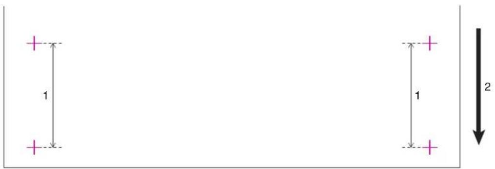
text_image
1 1 2| No. | Name |
| 1 | FeedLength |
| 2 | Media feeding direction |
- When the Confirm Print is complete, the printer enters Normal.
d. After the confirmation adjustment printing, cut the media.
4.4.3 Cutting media
- Measure the distance between the two pluses in the confirmation adjustment print using a ruler. Then, confirm that the distance matches the feeding length when printing.
a. If the distance does not match the feeding length, follow the procedure from Step 1 to Step 5 and readjust.
b. If the distance matches the feeding length, proceed to step 7.
- Performs Micro Adjustment Print.
a. Display the Dist.Adj menu on Operation panel in the same way as in Step 1.
b. Press the [+] key or [-] key on Operation panel to select "PF4: Micro Print".
c. Press the [Enter] key on Operation panel.
- For VJ-1638, "Warming up Skip ->E" is displayed on Operation panel. (This is not displayed for VJ-1638W since it does not perform warming up.)

CAUTION
While "Warming Up" is displayed, do not touch Platen and Media guide. They become very hot and you could burn yourself.
NOTE
- You can start printing during warming up. 14.4.7 Starting printing during warming up (VJ-1638 only)
- "Printing" is displayed on Operation panel. (VJ-1638 starts printing after warming up is complete.)
- Starts micro adjustment printing.

bar_stacked
| Category | Value | | -------- | ----- | | -0.2 | 0.1 | | -0.1 | 0.1 | | -0.05 | 0.1 | | ± 0 | 0.1 | | + 0.05 | 0.1 | | + 0.1 | 0.1 | | + 0.2 | 0.1 |-
After the micro adjustment printing is completed, "PF4:Micro Print" is displayed on Operation panel.
-
Refer to the illustrations below and check the printing result.

text_image
Input the adjustment value- Sets up Micro Adjustment Change.
a. Press the [+] key or [-] key on Operation panel to select "PF5: Micro Change".
b. Press the [Enter] key on Operation panel.
- "Micro Change: 0.00%" is displayed on Operation panel.
c. Press the [+] key or [-] key and enter the micro adjustment value according to the printing result in Step 7.
The optimal adjusted value has the least white lines or overlapping images. Use the number on the bottom right of the printing result as the adjusted value.
d. Press the [Enter] key on Operation panel.
• The micro adjustment value is saved.
- "PF5:Micro Change" is displayed on Operation panel.
- Press the [Menu] key on Operation panel.
• Operation panel returns to Normal.
- The adjustment of media feed compensation value is complete.
4.2.6.2 How to fix the media firmly
- Load the roll media.
3.4.2 Setting Roll Media
- Lower the media loading lever.

natural_image
Technical line drawing of a mechanical device with no visible text or symbols| No. | Name |
| 1 | Media loading lever |
- Adjust the Media feed compensation value again.
4.2.6.1 Procedure for the media feed compensation value
4.2.7 Installing Media holder plates
Variations in quality and use conditions can cause the edges of the media to curl, resulting in damage to the media by the print head surface.
To prevent this, use Media holder plates to reduce the amount of curling in the media.
Follow the procedure below to install Media holder plates.
- Display the Side Margin menu on Operation panel.
a. Press the [Menu] key on Operation panel.
- "Menu1: Setup>" is displayed on Operation panel.
- Operation panel shifts to the Setup menu display.
b. Press the [>] key on Operation panel.
- "Set1: User Type" is displayed on Operation panel.
c. Press the [+] key or [-] key to select Set3: Side Margin.
d. Press the [Enter] key on Operation panel.
- "Side Margin: ** mm" is displayed on Operation panel.
- The display shifts to the Side Margin menu.
5.1.3 Side Margin menu
NOTE
- The current setting value is displayed in the "**" of the Side Margin menu.
- Set up the margins (side margins) to 10 mm while printing.
NOTE
Set more than 10mm for the side margins.
In this section, the side margins are set to 10mm as a sample.
a. Press the [+] key or [-] key to select Side Margin: 10 mm.
b. Press the [Enter] key on Operation panel.
- After having saved the setting, "Set3: Side Margin" is displayed on Operation panel.
c. Press the [Menu] key on Operation panel.
• Operation panel returns to Normal.
- Load the roll media.
3.4.2 Setting Roll Media
- Set Media holder plates by sliding them from both sides of Platen.
NOTE
- Do not use Media holder plates for the media whose thickness is 400 µm (0.4mm) or thicker. The media holder plate may interfere with Print head.

text_image
Technical diagram of a printer with numbered parts and cross-sectional views highlighting internal components.| No. | Name |
| 1 | Roll media |
| 2 | Media holder plate |
| 3 | Media loading position |
| 4 | Platen |
- After installing Media holder plates, make sure that they do not interfere with media feeding.

CAUTION
- If the media jams when using Media holder plates, the plates may be deformed. When Media holder plates are deformed:
- Do not remove the clogged media by force.
- Stop using the printer.
Using the printer with deformed Media plates may damage Grid roller or Print heads.
Contact your local MUTOH dealer.
NOTE
- If there is interference with the media as it is fed through the printer after Media holder plates have been installed, Media holder plates should not be used.
- If Media holder plates are not used, return the plates to their initial positions as shown in the following figure.
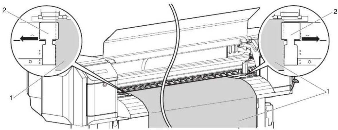
text_image
Technical diagram of a printer with labeled parts and two circular insets showing internal components.| No. | Name |
| 1 | Roll media |
| 2 | Media holder plates |
4.3 Menu setups on Operation panel
4.3.1 Menu setup procedure
Follow the procedure below to configure each setup menu.
-
Confirm that Operation panel is Normal.
-
Press the [Menu] key on Operation panel.

flowchart
graph TD
    A["Power"] --> B["Receiving Data"]
    C["Error"] --> D["Ink Low"]
    E["Head Height"] --> F["High"]
    E --> G["Low"]
    H["Output Mode"] --> I["Take Up @ 8"]
    H --> J["Auto Cut +"]
    K["Cleaning Mode"] --> L["Long"]
    K --> M["Normal"]
    K --> N["Short"]
    O["Nestle Check"] --> P["+"]
    Q["Pause"] --> R["Cancel"]
    S["Enter"] --> T["Cutting"]
    U["Forward Test"] --> V["+"]
    W["Forward Test"] --> X["+"]
- "Menu1: Setup>" is displayed on Operation panel.
- Press the [+] key or [-] key on Operation panel to select a setup item and press the [>] key.

flowchart
graph TD
    A["Power"] --> B["Receiving Data"]
    C["Error"] --> D["Ink Low"]
    E["Head Height"] --> F["High"]
    E --> G["Low"]
    H["Menu"] --> I["Nipple Check"]
    H --> J["Pause"]
    H --> K["Canon"]
    L["Output Mode"] --> M["Take Up @ 70"]
    L --> N["Auto Cut +"]
    O["Cleaning Mode"] --> P["Long"]
    O --> Q["Normal"]
    O --> R["Short"]
    S["Enter"] --> T["Cutting"]
    S --> U["Recycle"]
    V["Down"] --> W["Down"]
    X["Down"] --> Y["Down"]
    Z["Down"] --> AA["Down"]
• The settings will be confirmed.
- When setup items have a submenu, the display shifts to the next menu.
NOTE
- When a setup item has a submenu, ">" is displayed on the right end of LCD monitor of Operation panel.
-
For the general outline of each setup item, refer to "4.3.2 Panel setup menu overview".
-
The setting in the blinking part on LCD monitor of Operation panel can be changed. Press the [+] key or [-] key on Operation panel to change the setting.
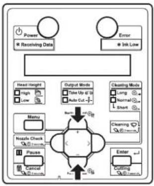
flowchart
graph TD
    A["Power"] --> B["* Receiving Data"]
    C["Error"] --> D["* Ink Low"]
    E["Head Height"] --> F["High"]
    E --> G["Low"]
    H["Menu"] --> I["Nzzle Check"]
    H --> J["Pause"]
    H --> K["Cancel"]
    L["Output Mode"] --> M["Take Up @ 10"]
    L --> N["Auto Cut -"]
    O["Cleaning Mode"] --> P["Long"]
    O --> Q["Normal"]
    O --> R["Short"]
    S["Clearing"] --> T["Enter"]
    U["Cutting"] --> V["Enter"]
    W["Gate"] --> X["Gate"]
    Y["Gate"] --> Z["Gate"]
    style A fill:#f9f,stroke:#333
    style C fill:#f9f,stroke:#333
    style E fill:#ccf,stroke:#333
    style L fill:#cfc,stroke:#333
    style O fill:#fcc,stroke:#333
    style U fill:#cff,stroke:#333
    style V fill:#ffc,stroke:#333
    style W fill:#fcc,stroke:#333
- To save the changed setting, press the [Enter] key on Operation panel.
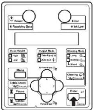
flowchart
graph TD
    A["Power"] --> B["* Receiving Data"]
    C["Error"] --> D["* Ink Low"]
    E["Head Height"] --> F["High"]
    E --> G["Low"]
    H["Output Mode"] --> I["Take Up @ 0"]
    H --> J["Auto Cut -"]
    K["Cleaning Mode"] --> L["Long"]
    K --> M["Normal"]
    K --> N["Short"]
    O["Menu"] --> P["Nozzle Check"]
    O --> Q["Pause"]
    O --> R["Cancel"]
    O --> S["Forward best"]
    T["Enter"] --> U["Unknown"]
- The setting is saved and the next setup item is displayed.
NOTE
- If you press the [Cancel] key without pressing the [Enter] key after changing a setting, the changed setting will not be saved.
- Press the [Cancel] key on Operation panel to exit from the setup.
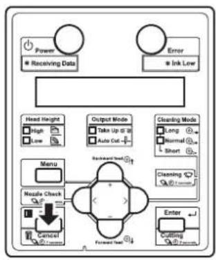
flowchart
graph TD
    A["Power"] --> B["Receiving Data"]
    C["Error"] --> D["Ink Low"]
    E["Head Height"] --> F["High"]
    E --> G["Low"]
    H["Menu"] --> I["Noise Check"]
    I --> J["Cancel"]
    K["Output Mode"] --> L["Take Up @ 18"]
    K --> M["Auto Out"]
    N["Cleaning Mode"] --> O["Long"]
    N --> P["Normal"]
    N --> Q["Short"]
    R["Forward Test"] --> S["(-)"]
    T["Enter"] --> U["Cutting"]
    V["Backward Test"] --> W["+"]
    X["(-)"] --> Y["+"]
- Return to the menu in the previous hierarchy.
4.3.2 Panel setup menu overview
This section explains the outline of each menu.
There are the following items in the Panel setup menu.
| Setup item Description | |
| Setup menu Various settings of the printer are configured. | |
| Test Print menu Performs nozzle check of Print head and setup list. | |
| Cleaning menu Performs head cleaning. | |
| Menu Option menu Sets up the contents of the Setup menu. | |
| Version menu Displays the versions of the firmware. | |
| Sleep Mode menu Sleep mode settings are configured. | |
| Display menu | Sets the language and unit displayed on LCD monitor of Operation panel. |
TIP
- For details of each setup item, refer to "5 Panel setup menu".
4.4 Operating from Operation panel
This section explains various functions that can be operated from Operation panel.
TIP
- For names and functions of each key, refer to "2.2.3 Operation panel".
4.4.1 Feeding media
You can feed the roll media at a position that you want.
Follow the procedure below to feed media.
- Confirm that Operation panel is Normal.
-
Check that Media loading lever is lowered.
-
Press the [Forward↓] key or the [Backward↑] key on Operation panel.
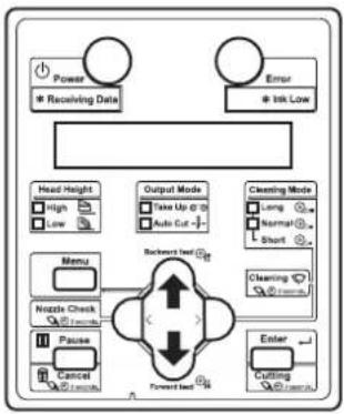
flowchart
graph TD
    A["Power<br>Receiving Data"] --> B["Head Height"]
    C["Error<br>Ink Low"] --> D["Output Mode"]
    D --> E["Backward load"]
    E --> F["Clearing Mode"]
    F --> G["Menu"]
    G --> H["Nipple Check"]
    H --> I["Pause"]
    I --> J["Cancel"]
    J --> K["Forward load"]
    K --> L["Enter"]
    L --> M["Cutting"]
• The media is fed forward or backward.
- Release the [Forward↓] key or the [Backward↑] key on Operation panel after feeding the media to the desired position.
4.4.2 Stopping printing operation
If you want to stop printing for some reason, operate as follows.
- Stop sending printing data from the computer to the printer.
- Press the [Cancel] key on Operation panel for more than 2 seconds.

flowchart
graph TD
    A["Power"] --> B["Receiving Data"]
    C["Error"] --> D["Ink Low"]
    E["Head Height"] --> F["High"]
    E --> G["Low"]
    H["Output Mode"] --> I["Take Up @ 70"]
    H --> J["Auto Cut +"]
    K["Cleaning Mode"] --> L["Long"]
    K --> M["Normal"]
    K --> N["Short"]
    O["Menu"] --> P["Nzzle Check"]
    P --> Q["Cancel"]
    R["Forward Test"] --> S["Enter"]
    T["Cutting"] --> U["Cutting @ 1/2/1/1/1/1/1/1/1/1/1/1/1/1/1/1/1/1/1/1/1/1/1/1/1/1/1/1/1"] --> P
    style P fill:#f9f,stroke:#333,stroke-width:2px
• The printer operates as follows.
| Printer status Operation with the [Cancel] key pressed for two seconds | |
| During printing | Terminates the printing, and deletes one data remaining in the printer. |
| Receiving data/analyzing data | Deletes the data already received and converted. |
NOTE
- If a large amount of data is saved on the printer, Operation panel may not return to Normal by a single [Cancel] key operation. In such cases, wait for a few seconds and press the [Cancel] key again for more than 2 seconds
4.4.3 Cutting media
This section explains how to cut media.
If Media ejection mode is set to Auto Cut, the printer cuts the media automatically after printing.
5.1.6 Output Mode menu
If you press the [Cutting] key on Operation panel more than two seconds while Operation panel is Normal, you can cut the media at the desired position.
Follow the procedure below to cut the roll media.
-
Confirm that Operation panel is Normal.
-
Press the [Cutting] key on Operation panel for more than 2 seconds.

flowchart
graph TD
    A["Power"] --> B["* Receiving Data"]
    C["Error"] --> D["* Ink Low"]
    E["Head Height"] --> F["High"]
    E --> G["Low"]
    H["Menu"] --> I["Nozzle Check"]
    H --> J["Pause"]
    H --> K["Cancel"]
    L["Output Mode"] --> M["Take Up @ 10"]
    L --> N["Auto Cut +"]
    O["Cleaning Mode"] --> P["Long"]
    O --> Q["Normal"]
    O --> R["Short"]
    S["Backward Test"] --> T["Forward Test"]
    U["Cutting"] --> V["OK"]
- The printer feeds the roll media to the length of the margin and cuts the media.
NOTE
- When loading the new roll media, cut the front edge of the media if it is not straight.
• The cutter is a consumable component.
Replace it periodically.
6.1.4 Replacing Cutter
- When the the media detection is set to "Off", the media cannot be cut automatically.
5.1.4 Media Set menu
4.4.4 Cutting media manually
This section explains how to cut the roll media manually.
Since VJ-1638 is equipped with Heaters, strictly comply with the following Cautions.

CAUTION
- Right after printing, Media guide becomes very hot. Allow Media guide to cool down before the next operation.
Follow the procedure below to cut the roll media.
-
Verify the following regarding the operational condition of the printer.
-
Printing or other operations are not in progress.
• Operation panel display is Normal. -
To change the position to cut the roll media, refer to "4.4.1 Feeding media" and advance the roll media to the desired cut position.
-
Open Front cover.
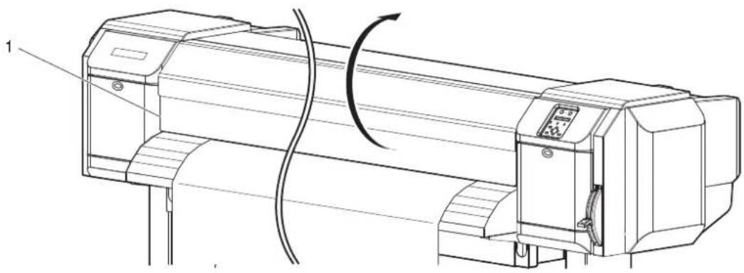
natural_image
Technical line drawing of a mechanical device with a rotating shaft and control panel (no text or symbols)| No. | Name |
| 1 | Front cover |
- Place a razor blade on Media cut groove on Media guide, and cut the roll media.
CAUTION
- Pay attention to the following points when cutting roll media. Mishandling Razor blade may cause a cut on your finger or hand.
- When you hold media, do not place your finger on Media cut groove.
- Move Razor blade slowly along Media cut groove.

text_image
Technical diagram of a printer with labeled parts and directional arrow indicating process flow| No. | Name |
| 1 | Media guide |
| 2 | Media cut groove |
| 3 | Razor blade |
• The procedure for cutting the roll media is complete.
NOTE
- When loading the new roll media, cut the front edge of the media if it is not straight.
4.4.5 Changing and confirming settings while printing
While the printer is operating, you can change or confirm settings for the Panel setup menu.
4.4.5.1 Procedure for changing and confirming settings while printing
Follow the procedure below to change or confirm settings for the Panel setup menu.
-
Confirm that the printer is in one of the following conditions.
-
Receiving data
- Analyzing data
-
Printing
-
Press the [Menu] key on Operation panel.
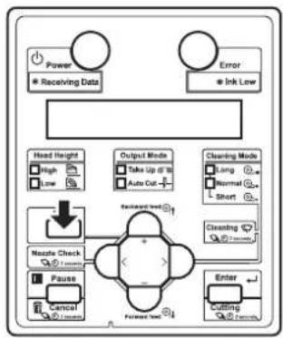
flowchart
graph TD
    A["Power"] --> B["Receiving Data"]
    C["Error"] --> D["Ink Low"]
    E["Head Height"] --> F["High"]
    E --> G["Low"]
    H["Output Mode"] --> I["Take Up if 10"]
    H --> J["Auto Cut"]
    K["Cleaning Mode"] --> L["Long"]
    K --> M["Normal"]
    K --> N["Short"]
    O["Nzzle Check"] --> P["+"]
    Q["Pause"] --> R["Cancel"]
    S["Enter"] --> T["Cutting"]
    U["Forward Test"] --> V["Forward Test"]
    W["Feedback Loop"] --> X["+"]
    Y["Feedback Loop"] --> Z["-"]
- The following will be displayed on Operation panel. VJ-1638: Menu1: Temperature VJ-1638W: Menu1: PF Micro Adj.
- Press the [+] key or [-] key to change or confirm settings.
NOTE
- For the setting items whose settings can be changed or confirmed, refer to "4.4.5.2 Settings that can be changed or confirmed while printing".
4.4.5.2 Settings that can be changed or confirmed while printing
NOTE
- When you change a setting during operation, be sure to select "Backup" to save the setting that you changed. If the printer returns to Normal without "Backup" being selected, the changed setting is not saved.
• The following setting items are only for VJ-1638.
- Temperature
- Pre-heater
- Platen heater
• Dryer
| Setup item Setting Description Reference | |||
| Temperature(VJ-1638 only) | Pre Checks the current temperature of Pre-heater. — | ||
| Platen Checks the current temperature of Platen heater. | |||
| Dryer Checks the current temperature of Dryer. | |||
| Pre-heater(VJ-1638 only) | Off / 30°C to 50°C | Changes the temperature of Pre-heater. | 5.1.1.1.4 Pre-heater menu (VJ-1638 only) |
| Platen heater(VJ-1638 only) | Off / 30°C to 50°C | Changes the temperature of Platen heater. | 5.1.1.1.5 Platen Heater menu (VJ-1638 only) |
| Dryer(VJ-1638 only) | Off / 30°C to 50°C | Changes the temperature of Dryer. | 5.1.1.1.6 Dryer menu (VJ-1638 only) |
| PF Adjust | -5.00% to 0.00% to 5.00% | Change the feed adjustment value. | 5.1.1.1.3 Media feed compensation |
| Backup | — | • [Enter] key: Save the changed setting. | — |
| — | • [Cancel] key: The printer returns to Normal. | ||
4.4.6 Pausing printing
It is possible to pause to print during printing.
Follow the procedure below to pause or restart printing.
NOTE
- If the printing is paused, the print quality will not be guaranteed.
-
Check that the printer is in operating.
-
Press the [Pause] key on Operation panel.

flowchart
graph TD
    A["Power"] --> B["Receiving Data"]
    C["Error"] --> D["Ink Low"]
    E["Head Height"] --> F["High"]
    E --> G["Low"]
    H["Output Mode"] --> I["Take Up to 3"]
    H --> J["Auto Cut"]
    K["Cleaning Mode"] --> L["Long"]
    K --> M["Normal"]
    K --> N["Short"]
    O["Menu"] --> P["Nzzle Check"]
    O --> Q["Pause"]
    R["Forward Int"] --> S["Enter"]
    T["Cutting"] --> U["Cutting"]
• The printer pauses printing.
- "PrintRestart -> ENTER" is displayed on Operation panel.
- To restart printing, press the [Enter] key on Operation panel.

flowchart
graph TD
    A["Power<br>* Receiving Data"] --> B["Head Height<br>High<br>Low"]
    C["Error<br>* Ink Low"] --> D["Output Mode<br>Take Up @ 10<br>Auto Cut"]
    E["Cleaning Mode<br>Long Normal Short"] --> F["Menu<br>Nettle Check<br>Pause Cancel"]
    G["Cleaning Mode<br>Normal Short"] --> H["Forward Test"]
    I["Enter"] --> J["Forward Test"]
    K["Feedback"] --> L["Forward Test"]
    M["Feedback"] --> N["Forward Test"]
• The printer restarts printing.
4.4.7 Starting printing during warming up (VJ-1638 only)
You can start printing while the printer is warming up, even though the heater temperature has not reached the set temperature.
NOTE
- Even when you start printing during warming up, warming up continues until the temperature reaches the set temperature.
- If you start printing during warming up, print quality will not be guaranteed.
- Confirm that the printer is warming up.
- "Warming Up" is displayed on Operation panel.
- Print data will be sent.
- "Warming Up" and "Skip ->E" is displayed on Operation panel.

While "Warming Up" is displayed, do not touch Platen and Media guide. You could burn yourself.
- To start printing during warming up, press the [Enter] key on Operation panel.

flowchart
graph TD
    A["Power"] --> B["Receiving Data"]
    C["Error"] --> D["Ink Low"]
    E["Head Height"] --> F["High"]
    E --> G["Low"]
    H["Output Mode"] --> I["Take Up @ 30"]
    H --> J["Auto Cut -"]
    K["Cleaning Mode"] --> L["Long"]
    K --> M["Normal"]
    K --> N["Short"]
    O["Menu"] --> P["Backward Mode"]
    Q["Nozzle Check"] --> R["+"]
    S["Pause"] --> T["-"]
    U["Cancel"] --> V["Forward Mode"]
    W["Enter"] --> X["Return Mode"]
• The printer starts printing.
4.5 Using Spectrophotometer (VJ-1638 only)
NOTE
- VJ-1638W cannot be equipped with Spectrophotometer (SPECTROVUE VM-10).
The optional spectrophotometer (SPECTROVUE VM-10) can be attached to print and measure the color target. Performing color calibration or profiling of the printer by using RIP software compatible with SPECTROVUE VM-10 enables printing with more accurate colors. For Software server RIP (option), contact MUTOH local dealer.
Follow the procedure below.

CAUTION
When using VM-10, make sure to use the media whose thickness is less than 0.7mm. If you use the media thicker than 0.7mm, VM-10 and the media come into contact and VM-10 may be damaged.
NOTE
- Do not install the printer in a place that is subject to strong light (sunlight, etc).
Getting strong light on the color measurement may affect the measurement accuracy. - To use Spectrophotometer (SPECTROVUE VM-10), the printer setting must be as follows. Make sure the setting before use.
• Media detection: Top&Width or Width
5.1.4 Media Set menu
• Media ejection mode: Off or Auto Cut
5.1.6 Output Mode menu
• Head height: Low or Mid
14.2.5 Head height adjustment - When the color target is printed on the translucent or colored media, or the media with patterned indented surfaces, color measurement may not be accurate.
- Read the Operation Manual of Spectrophotometer (SPECTROVUE VM-10) as well.
-
When measuring colors, make sure that the color target is dry. If it is not dry enough, the ink may adhere to the pressurizing rollers of the printer.
-
Connect the printer and computer.
3.7 Connecting the printer to PC - Turn the printer ON.
-
Set the media.
3.4 Loading media -
Set the user type setting.
3.4.3 Setting the User Type Setting
- When the user type setting and media initial operation are complete, "Ready to Print" is displayed on Operation panel.
- Start RIP software to print and measure the color target.
NOTE
- For the setting and operations of the RIP software, refer to its operation manual.
• The printer starts printing the color target.
- "Printing" is displayed on Operation panel.
• After printing is complete, "Attaching instrument [ENTER]" is displayed on Operation panel.
NOTE
- Do not open the covers or move media loading lever during printing.
- Press the [Enter] key.
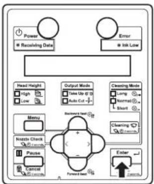
flowchart
graph TD
    A["Power"] --> B["Receiving Date"]
    C["Error"] --> D["Ink Low"]
    E["Head Height"] --> F["High"]
    E --> G["Low"]
    H["Output Mode"] --> I["Take Up @ 3"]
    H --> J["Auto Cut -"]
    K["Cleaning Mode"] --> L["Long"]
    K --> M["Normal"]
    K --> N["Short"]
    O["Menu"] --> P["Nzzle Check"]
    O --> Q["Pause"]
    O --> R["Cancel"]
    S["Backward test"] --> T["Forward test"]
    U["Enter"] --> V["Forward test"]
- "Wait for a while..." is displayed on Operation panel.
- Print head moves to the left.
- "Open left mainte. cover." is displayed on Operation panel.
- Open Maintenance cover on the left of the printer.
- "Remove connector cap and attach instrument. [ENTER]" is displayed on Operation panel.

natural_image
Technical line drawing of a mechanical device with a paper roller and control panel (no text or symbols)| No. | Name |
| 1 | Maintenance cover |
NOTE
- When a certain time has passed without opening Maintenance cover, Print head returns toward the right side of the printer for protection. "Attaching instrument [ENTER]" is displayed. Restart from Step 6.
- Firmly pinch the tabs on both sides of the connector cap with your fingers, pull the connector cap forward to remove it from Print head.
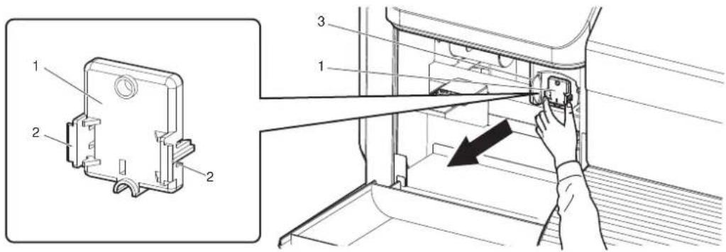
text_image
Technical diagram showing a mechanical assembly with labeled parts and a hand adjusting a component, including an inset view of a housing component.| No. | Name |
| 1 | Connector cap |
| 2 | T a b s |
| 3 | Print head section |
- Press the release buttons on both sides of spectrophotometer (SPECTROVUE VM-10), install it to the connector of Print head.

text_image
Technical diagram showing a device with labeled parts and an inset view of the device's internal structure.| No. | Name |
| 1 | Spectrophotometer |
| 2 | Release buttons |
| 3 | Print head section |
| 4 | Connector |
NOTE
- Make sure that Spectrophotometer is NOT installed at an angle, and that there in no gap between the connector and Spectrophotometer.
-
Press the [Enter] key.
-
"Wait for a while..." is displayed on Operation panel.
- The printer checks the connection between the printer and Spectrophotometer.
- "Set white plate, then close left maintenance cover." is displayed on Operation panel.

flowchart
graph TD
    A["Power"] --> B["* Receiving Data"]
    C["Error"] --> D["* Ink Low"]
    E["Menu"] --> F["Nozzle Check"]
    G["Pause"] --> H["Cancel"]
    I["Forward Lead"] --> J["Enter"]
    K["Backward Lead"] --> L["Output Mode"]
    M["Cleaning Mode"] --> N["Take Up @ 0"]
    O["Light"] --> P["Auto Cut"]
    Q["Normal"] --> R["Short"]
    S["Short"] --> T["Long"]
    U["External"] --> V["External"]
- Remove the white reference plate from the plate installation place, turn it over so that the white side faces up, and install it back to the original place.
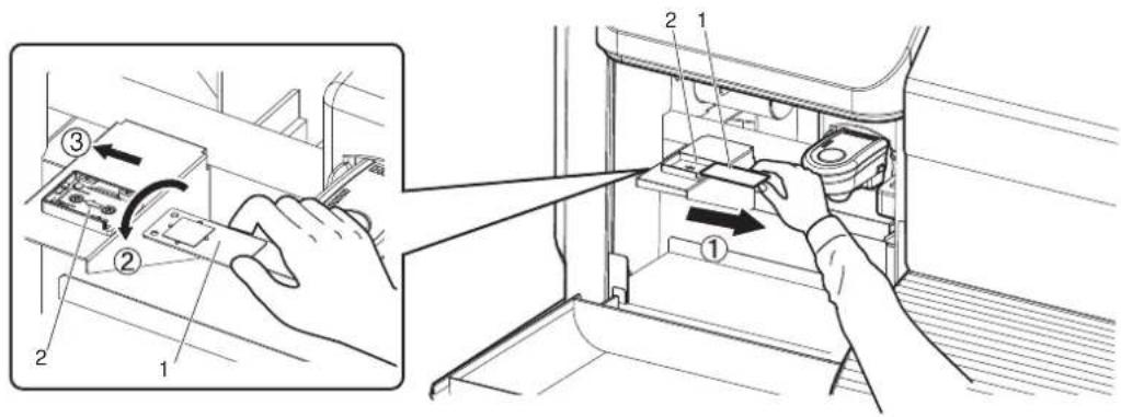
text_image
Technical diagram showing a hand inserting a component into a refrigerator, with numbered parts and directional arrows indicating assembly steps.| No. Name |
| 1 White reference plate |
| 2 Plate installation place |
NOTE
- Before measuring the color target, make sure that the white side of the white reference plate is facing up.
If the black side is facing up, it will not be measured accurately.
- Close Maintenance cover.

natural_image
Technical line drawing of a mechanical device with internal components and a cable (no text or symbols)| No. | Name |
| 1 | Maintenance cover |
- Print head moves to the right.
-
"Wait for a while..." is displayed on Operation panel.
-
When "Start measurement [ENTER]" is displayed on Operation panel, press the [Enter] key.
-
Spectrophotometer starts measuring the color target.
- "Measuring..." is displayed on Operation panel.
• After measuring is complete, "Detaching instrument [ENTER]" is displayed on Operation panel.
NOTE
• Color measurement starts either automatically or manually, depending on the RIP software feature. The steps above are for manual measurement.
- When the measurement starts automatically, "Ink Drying xxxxxs" (xxxxx is a number) may be displayed on Operation panel.
- Do not open the covers or move media loading lever during measuring.
- Press the [Enter] key.
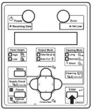
flowchart
graph TD
    A["Power"] --> B["Receiving Data"]
    C["Error"] --> D["Ink Low"]
    E["Head Height"] --> F["High"]
    E --> G["Low"]
    H["Output Mode"] --> I["Take Up @ 10"]
    H --> J["Auto Cut -"]
    K["Cleaning Mode"] --> L["Long"]
    K --> M["Normal"]
    K --> N["Short"]
    O["Menu"] --> P["Nozzle Check"]
    O --> Q["Pause"]
    O --> R["Cancel"]
    S["Backward load"] --> T["Forward load"]
    U["Enter"] --> V["Tooth"]
    W["OK"] --> X["Tooth"]
- "Wait for a while..." is displayed on Operation panel.
- Print head moves to the left.
-
"Open left mainte. cover."is displayed on Operation panel.
-
Open Maintenance cover on the left of the printer.
- Detach instrument and set connector cap. [ENTER] is displayed on Operation panel.

natural_image
Technical line drawing of a printer with a paperclip and control panel, showing internal components (no text or symbols)| No. | Name |
| 1 | Maintenance cover |
- While pressing the release buttons on both sides of Spectrophotometer, pull it forward to remove it from Print head.
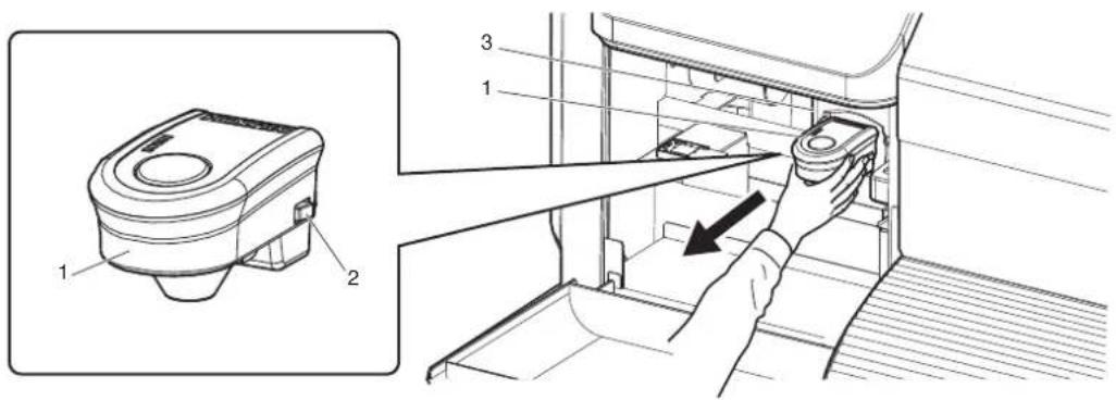
text_image
Technical diagram showing a device with labeled parts and an inset view of the device's internal structure.| No. | Name |
| 1 | Spectrophotometer |
| 2 | Release buttons |
| 3 | Print head section |
- Firmly pinch the tabs on both sides of Connector cap with your fingers, and install it to the connector of Print head.

text_image
Technical diagram showing a device's internal components with numbered parts and an inset view of the housing.| No. | Name |
| 1 | Connector cap |
| 2 | T a b s |
| 3 | Print head section |
| 4 | Connector |
- Press the [Enter] key.
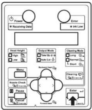
flowchart
graph TD
    A["Power"] --> B["* Receiving Data"]
    C["Error"] --> D["* Ink Low"]
    E["Head Height"] --> F["High"]
    E --> G["Low"]
    H["Menu"] --> I["Nzzle Check"]
    H --> J["Pause"]
    K["Output Mode"] --> L["Take Up or in"]
    K --> M["Auto Cut"]
    N["Cleaning Mode"] --> O["Long"]
    N --> P["Normal"]
    N --> Q["Short"]
    R["Backward load"] --> S["+"]
    T["Forward load"] --> U["-"]
    V["Enter"] --> W["1.0ms"]
    X["Input"] --> Y["1.0ms"]
- "Wait for a while..." is displayed on Operation panel.
-
"Remove white plate, then close left maintenance cover." is displayed on Operation panel.
-
Remove the white reference plate from the plate installation place, turn it over so that the black side faces up, and install it back to the original place.
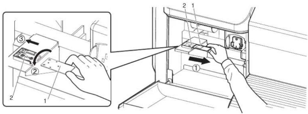
text_image
Technical diagram showing a hand inserting a device into a refrigerator, with numbered parts and directional arrows indicating assembly or operation.| No. Name |
| 1 White reference plate |
| 2 Plate installation place |
NOTE
- When White reference plate is not in use, make sure that it is turned over facing down to avoid any contamination.
-
Close Maintenance cover.
-
"Ready to Print" is displayed on Operation panel.
- For the subsequent operations, follow the instructions of the RIP software.

natural_image
Technical line drawing of a mechanical device with internal components and a cable (no text or symbols)| No. | Name |
| 1 | Maintenance cover |
5 Panel setup menu
The section explains the Setup menu of the printer.
| Setup item Description | |
| Setup menu Various settings of the printer are configured.5.1 Setup menu | |
| Test Print menu Performs nozzle check of Print head and setup list.5.2 Test Print Menu | |
| Cleaning menu Performs head cleaning.5.3 Cleaning menu | |
| Menu Option menu Sets up the contents of the Setup menu.5.4 Menu Option menu | |
| Version menu Displays the versions of the firmware.5.5 Version menu | |
| Sleep Mode menu Sleep mode settings are configured.5.6 Sleep Mode menu | |
| Display Sets the language and unit displayed on LCD monitor of Operation panel.5.7 Display menu |
TIP
- The < > parts in each list are factory default settings (default).
5.1 Setup menu
Various settings of the printer are configured.
| Setup item Description | |
| User Type Sets the user type setting for printing.·[Enter] key: shifts to the sub menu.5.1.1 User Type menu | |
| Spitting Sets up the spitting operation while printing.·[Enter] key: shifts to the sub menu.5.1.2 Spitting menu | |
| Side Margin Specifics the right and left margins of printed media.·[Enter] key: shifts to the sub menu.5.1.3 Side Margin menu | |
| Media Initial Sets whether to detect the media width and edge while initializing the media.·[Enter] key: shifts to the sub menu.5.1.4 Media Set menu | |
| Media Width | Specifies the media width between the loading mark and the left end of the media if media detection is not performed during media initialization.Displays the detected media width if media detection is performed during media initialization.·[Enter] key: shifts to the sub menu.5.1.5 Media Width menu |
| Output mode Sets the media ejection method after printing.·[Enter] key: shifts to the sub menu.5.1.6 Output Mode menu | |
| Method of Cut Sets the media cutting method after printing.·[Enter] key: shifts to the sub menu.5.1.7 Method of Cut menu | |
| Origin Sets the beginning of printing (origin) of the print data.·[Enter] key: shifts to the sub menu.5.1.8 Origin menu | |
| Prev. Stick Sets up to prevent media from sticking when printing starts.(This function is not displayed for VJ-1638W.)·[Enter] key: shifts to the sub menu.5.1.9 Prev. Stick menu (VJ-1638 only) | |
| Standby IIcating | Sets the time to preheat IIcater while the printer is in the standby mode.(This function is not displayed for VJ-1638W.)·[Enter] key: shifts to the sub menu.5.1.10 Standby Heating menu (VJ-1638 only) |
| Head Travel Sets up the range that Print head moves while printing.·[Enter] key: shifts to the sub menu.5.1.11 Head Travel menu | |
| Multi Strike | Sets up the overwrite count per line.·[Enter] key: shifts to the sub menu.5.1.12 Multi Strike menu |
| Strike Wait | Sets up the waiting time while overwrite printing.·[Enter] key: shifts to the sub menu.5.1.13 Strike Wait menu |
| Setup item | Description |
| Slant Check Sets up slanting detection during media loading.·[Enter] key: shifts to the sub menu.5.1.14 Slant Check menu | |
| Auto Cleaning | Sets up the time for auto cleaning during standby, before printing, and during printing.·[Enter] key: shifts to the sub menu.5.1.15 Auto Cleaning menu |
| Ink Status | Displays the various information about Ink cartridges (ink status) that are installed in Slots.·[Enter] key: shifts to the sub menu.5.1.16 Ink Status menu |
| Roll Length Sets up the roll media length.·[Enter] key: shifts to the sub menu.5.1.17 Roll Length menu | |
| Exhaust fan Set the operation of Exhaust fan.·[Enter] key: shifts to the sub menu.5.1.18 Exhaust Fan menu | |
| Longstore Wash Print head with the cleaning fluid.·[Enter] key: shifts to the sub menu.5.1.19 Longstore menu | |
| CR Maintenance Performs maintenance.·[Enter] key: shifts to the sub menu.5.1.20 CR Maintenance menu | |
| Initialization Returns the settings of the printer to default.·[Enter] key: shifts to the sub menu.5.1.21 Initialization menu | |
| Life Times Displays the operational life time of each part.·[Enter] key: shifts to the sub menu.5.1.22 Life Times menu | |
| IP Address Sets the IP address of the printer.·[Enter] key: shifts to the sub menu.5.1.23 IP Address menu | |
| Subnet Mask Sets the subnet mask of the printer.·[Enter] key: shifts to the sub menu.5.1.24 Subnet Mask menu | |
| Gateway | Sets the gateway.·[Enter] key: shifts to the sub menu.5.1.25 Gateway menu |
| Temporary Displays the settings of "Off" or "ALL Off" in the Selection menu in the Setup menu temporarily.·[Enter] key: returns to the previous menu with all set up items displayed.·[Cancel] key: returns to the previous status in the Selection menu when the Setup menu is displayed.5.4 Menu Option menu | |
| — | ·[Cancel] key: shifts to the previous menu.5 Panel setup menu |
5.1.1 User Type menu
Select the user type setting for printing.
| Setup item Setting | Description | |
| User Type Type 1 Sets the user | type setting for printing. | It is possible to set 15 different user settings as "Type 1 to 15" for printing.[Enter] key: shifts to the sub menu.5.1.1.1 User Type advanced setup menu |
| Type 2 | ||
| ... | ||
| Type 14 | ||
| Type 15 | ||
| — • [Cancel] key: saves the setting and shifts to the previous menu.5.1 Setup menu | ||
5.1.1.1 User Type advanced setup menu
Various settings on the user type settings are configured.
In User Type menu, 15 different settings can be set as Type 1 to 15 for the following printing operation.
NOTE
- If media other than recommended one is used, the following problems may occur.
• Media detection error
- Slant, torn, and wrinkle of media
- Media jams
- Favorable print quality cannot be obtained due to blots, blurs or dirt of ink.
• End detection of roll media cannot be performed, etc.
The problems caused by the use of the media other than recommended one will not be covered by the warranty and repair expenses will be paid by the customer.
For details, contact your local MUTOH dealer.
| Setup item Setting Description | ||
| Type 1 to 15 | Print Mode | Sets up the print mode according to the usage of print data or print speed.·[Enter] key: shifts to the sub menu.5.1.1.1.1 Print Mode menu |
| Adjust Print Sets up when | adjusting the printer for the optimum quality of image print.·[Enter] key: shifts to the sub menu.5.1.1.1.2 Adjust Print menu | |
| PF Adjust Sets up various | settings on the media feed compensation.·[>] key: shifts to the sub menu.5.1.1.1.3 Media feed compensation | |
| Pre-heater Sets the temperature of Pre-heater. | ||
| Platen heater Sets the temperature of Platen heater. | ||
| Dryer Sets the temperature of Dryer. | ||
| Vacuum Fan Sets up vacuum fan operation.·[Enter] key: shifts to the sub menu.5.1.1.1.7 Vacuum Fan menu | ||
| — | ·[Cancel] key: shifts to the previous menu.5.1.1 User Type menu | |
5.1.1.1.1 Print Mode menu
Settings for print quality (print mode) are set according to the usage of print data or print speed.
NOTE
After setting the Print mode, the display changes to Effect menu.
Effect menu
| Setup item Setting Description | |
| Mode Quality 1 Sets up print mode. | Quality 1 to 4:Suitable for printing photos. Sets up to perform high quality printing.Graphics 1 to 2:Suitable for printing photos. Sets up to perform standard printing.Banner 1 to 4:Suitable for outdoor signs and test printing. Sets up to perform high speed printing.Displays details of each print mode while pressing [>] key.Details of print mode |
| Quality 2 | |
| Quality 3 | |
| Quality 4 | |
| Graphics 1 | |
| Graphics 2 | |
| Banner 1 | |
| Banner 2 | |
| Banner 3 | |
| Banner 4 | |
| — • [Enter] key: saves the setting and shifts to the sub menu.Effect menu• [Cancel] key: cancels the setting and shifts to the previous menu.5.1.1.1 User Type advanced setup menu | |
NOTE
- The printed images can be uneven depending on the media and print mode. In such cases, use the following mode to clear unevenness.
- When using bidirectional print mode (refer to the following chart Details of print mode), switch it to unidirectional print mode.
- When using Graphics 1 to 2, change it to Quality 1 to 4.
- When the selected print mode of the user type is Graphics 1 or Graphics 2, Palette menu is not displayed.
3.5.4 Palette print
Details of print mode
The set values of print quality that are registered in each print mode are as follows.
NOTE
- In the chart below, the print speed becomes faster as the condition is closer to the following cases.
• Having fewer number of passes
• Having lower resolution
- Printing direction is bidirectional
In actual printing, the selected effect affects the printing speed.

Effect menu
| Print Mode Resolution Pass Direction | ||
| Quality 1 1440p1440dpi 16 times Uni (Uni-Direction) | ||
| Quality 2 1440p1440dpi 16 times Bi (Bi-Direction) | ||
| Quality 3 720 x 1440dpi 8 times Uni (Uni-Direction) | ||
| Quality 4 720 x 1440dpi 8 times Bi (Bi-Direction) | ||
| Graphics 1 720 x 1080dpi 6 times Uni (Uni-Direction) | ||
| Graphics 2 720 x 1080dpi 6 times Bi (Bi-Direction) | ||
| Banner 1 720 x 720dpi 4 times Uni (Uni-Direction) | ||
| Banner 2 720 x 720dpi 4 times Bi (Bi-Direction) | ||
| Banner 3 360 x 720dpi 2 times Uni (Uni-Direction) | ||
| Banner 4 360 x 720dpi 2 times Bi (Bi-Direction) |
Effect menu
Sets up the Effect menu.
Set up this menu when you want to improve print quality by adjusting the set print mode.
NOTE
- The print quality may not be improved depending on the printing condition.
| Setup item Setting | Description | |
| Effect*1 The Effect function is not used. | ||
| Wave The printing joint will be the wave form.The print quality may be improved than None. | ||
| Fine&Fuzz The printing joint will shade off as the wave form.Perform the printing at slower speed than "Wave". | ||
| *1 The printing joint will shade off.Set this when there is horizontal unevenness in Fine&Fuzz Prints at a slower speed than Fine&Fuzz | ||
| A-S.Fine&Wave Performs "Wave" printing using the left side of the of Print head.Since only half of Print head nozzles are used, printing speed becomes a half of "Wave".Set up this menu to improve the print quality compared with "Fine&Fuzz". If used when one side of the nozzles are clogged, quality deterioration may be avoided. | ||
| B-S.Finc&WavePerforms "Wave" printing using the right side of the of Print head.Since only half of Print head nozzles are used, printing speed becomes a half of "Wave".Set up this menu to improve the print quality compared with "Fine&Fuzz". If used when one side of the nozzles are clogged, quality deterioration may be avoided. | ||
| —• [Enter] key: saves the setting and shifts to the previous menu.• [Cancel] key: cancels the setting and shifts to the previous menu.5.1.1.1.1 Print Mode menu | ||
*1 The initial values of effect differ as shown below depending on the selected print mode.
| Print Mode Initial effect value | |
| Quality 1 to 4 | Fine&Fog |
| Graphics 1 to 2 | Fine&Fog |
| Banner 1 to 2 | Fine&Fog |
| Banner 3 to 4 | None |
5.1.1.1.2 Adjust Print menu
Sets up when adjusting the printer for the optimum quality of image print.
NOTE
- This printer was adjusted at the factory shipment so that it obtains the optimum printing quality. Adjust the quality if the print quality changes after the installation environment or the media is changed.
- When newly setting or changing the user type setting after adjusting Standard adjust print, make sure to adjust print.
- Since all print modes are adjusted at once after performing Custom adjust print, adjust print is not required even after changing the print mode..
- When specifying a print mode which is different from the mode set in the user type setting, adjust all print modes in the Custom adjust print first.
| Setup item Setting | Description | |
| Adjust Print Standard Adjusts | only the print mode in the user | type setting which is currently set.Standard Adjust Print menu |
| Custom Perform adjustment for all print modes.Custom Adjust Print menu | ||
| — [Cancel] key: | shifts to the previous menu.5.1.1.1 User Type advanced setup menu | |
Standard Adjust Print menu
Adjusts only the print mode in the user type setting which is currently set.
| Setup item Setting | Description | |
| Adjustment Confirmation pattern | Print the test pattern for the alignment. Check before adjusting.3.6.1.1 Standard confirmation pattern | |
| Rough adjustment pattern Perform this when the degree of misalignment is big.Print Adjust pattern and enter the set value.3.6.1.2 Standard rough adjustment pattern | ||
| Micro adjustment pattern Perform this when the degree of misalignment is small.Print Adjust pattern and enter the set value.3.6.1.3 Standard micro adjustment pattern | ||
| — • [Cancel] key: shifts to the previous menu.5.1.1.1.2 Adjust Print menu | ||
Custom Adjust Print menu
Perform adjustment for all patterns (A to F).
All print modes will be adjusted.
| Setup item Setting | Description | |
| Adjustment | Confirmation pattern | The test patterns of A to F will be printed for Adjust print. Check before adjusting.3.6.2.1 Custom confirmation pattern |
| Rough adjustment pattern Perform this when the degree of misalignment is big.Print Adjust patterns A to F and enter the set values.3.6.2.2 Custom rough adjustment pattern | ||
| Adj. PatternALL Perform this when the degree of misalignment is small.Print Adjust patterns A to F and enter the set values.3.6.2.3.1 Adj. PatternALL | ||
| Adj. PatternA When the degree of misalign is small, print out one of the Adjust patterns and enter the set value.3.6.2.3.2 Individual Adj. pattern | ||
| Adj.PatternB | ||
| Adj.PatternC | ||
| Adj.PatternD | ||
| Adj.PatternE | ||
| Adj. Pattern F | ||
| — • [Cancel] key: shifts to the previous menu.5.1.1.1.2 Adjust Print menu | ||
5.1.1.1.3 Media feed compensation
Sets up various settings on the media feed compensation.
| Setup item Setting | Description | |
| PF Init.Adj.Print Performs Initial | Adjust Print. | • [Enter] key: shifts to the sub menu.15(1) Init.Adj.Print menu |
| Init.Adj.Change Sets up Initial | Adjust Change.• [Enter] key: shifts to the sub menu.15(2) Init.Adj.Change menu | |
| Confirm Print Performs Confirm Print. | • [Enter] key: shifts to the sub menu.15(3) Confirm Print menu | |
| Micro Adj. Print Performs Micro Adjustment Print. | • [Enter] key: shifts to the sub menu.15(4) Micro Adj. Print menu | |
| Micro Adj.Change Sets up Micro Adjustment Change. | • [Enter] key: shifts to the sub menu.15(5) Micro Change menu | |
| — • [Cancel] key: shifts to the previous menu.15 5.1.1.1 User Type advanced setup menu | ||
(1) Init.Adj.Print menu
Performs Initial Adjust Print.
| Setup item Setting | Description | |
| FeedLength 100mm to <250mm> to 500mm | Changes the length (feed length) of the media feed direction for initial adjust print.·[Enter] key:Determines the setting."Printing" is displayed on Operation panel and initial adjust print starts.After printing, the printer enters Normal. | |
| — • [Cancel] key: cancels the setting and shifts to the previous menu.5.1.1.1.3 Media feed compensation | ||
(2) Init.Adj.Change menu
Sets up Initial Adjust Change.
| Setup item Setting | Description | |
| Init. The setting value of | "FeedLength" in the initial adjustment printing ±50.0mm | Sets up Initial Adjust Change.Example: When the value of "FeedLength" in the initial adjustment printing is set to 250mm, the adjustment range of this menu is 200mm to 300mm. |
| — • [Enter] key: | saves the setting and shifts to the previous menu.• [Cancel] key: cancels the setting and shifts to the previous menu.5.1.1.1.3 Media feed compensation |
(3) Confirm Print menu
Performs Confirm Print.
| Setup item Setting | Description | |
| FeedLength 100mm to <250mm> to 500mm | Changes the length (feed length) of the media feed direction for Confirm Print.·[Enter] key:Determines the setting."Printing" is displayed on Operation panel and initial adjust print starts.After printing, the printer enters Normal. | |
| — • [Cancel] key: cancels the setting and shifts to the previous menu.5.1.1.1.3 Media feed compensation | ||
(4) Micro Adj. Print menu
Performs Micro Adjustment Print.
| Setup item Setting | Description | |
| Micro Adj. Print — Prints the following PF pattern (micro adjustment) with a focus on the micro adjustment value.0%, ±0.05%, ±0.1%, ±0.2% | ||
| — • [Cancel] key: shifts to the previous menu.If during printing, printing will be paused.5.1 Setup menu | ||
(5) Micro Change menu
Sets up Micro Adjustment Change.
| Setup item Setting | Description | |
| Micro Adj.Change -5.00%~<0.00%>~5.00% Sets up Micro Adjustment Change. | ||
5.1.1.1.4 Pre-heater menu (VJ-1638 only)
Sets the temperature of Pre-heater.
Set to curb a rapid temperature change at the printing portion by pre-heating the media before printing.
NOTE
• This function is not displayed for VJ-1638W.
- The set temperature of Pre-heater differs depending on the media.
| Setup item Setting | Description | |
| Pre-heater Off / <30°C> to 50°C | Sets the temperature of Pre-heater. |  1.Roll media2.Pre-heater3.Print head 1.Roll media2.Pre-heater3.Print head |
| — • [Enter] key: | saves the setting and shifts to the previous menu.• [Cancel] key: cancels the setting and shifts to the previous menu.5.1.1.1 User Type advanced setup menu |
5.1.1.1.5 Platen Heater menu (VJ-1638 only)
Sets the temperature of Platen heater.
Set to improve print quality by allowing the ink to settle by heat.
NOTE
• This function is not displayed for VJ-1638W.
- The set temperature of Platen heater differs depending on the media.
| Setup item Setting | Description | |
| Platen heater Off / <30°C> to 50°C Sets the temperature of Platen heater. | 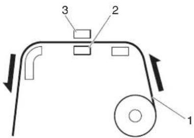 1.Roll media2.Platen heater3.Print head 1.Roll media2.Platen heater3.Print head | |
| — • [Enter] key: saves the setting and shifts to the previous menu.• [Cancel] key: cancels the setting and shifts to the previous menu.[44c8] '5.1.1.1 User Type advanced setup menu | ||
5.1.1.1.6 Dryer menu (VJ-1638 only)
Sets the temperature of Dryer.
Set to dry the print side after printing.
NOTE
• This function is not displayed for VJ-1638W.
- The set temperature of Dryer differs depending on the media.
| Setup item Setting | Description | |
| Dryer Off / <30°C> to 50°C S | Sets the temperature of Dryer. |  1.Roll media2.Dryer3.Print head 1.Roll media2.Dryer3.Print head |
| — • [Enter] key: | saves the setting and shifts to the previous menu.• [Cancel] key: cancels the setting and shifts to the previous menu.5.1.1.1 User Type advanced setup menu |
5.1.1.1.7 Vacuum Fan menu
Sets up vacuum fan operation.
| Setup item Setting | Description | |
| Vacuum Fan Low Set this if th | ere is a possibility of paper jamming from media feed failure when the setting is Middle. | |
| Middle Set this if there is a possibility of paper jamming from media feed failure when the setting is High. | ||
| Set when using general media. | ||
| — • [Enter] key: saves the setting and shifts to the previous menu.• [Cancel] key: cancels the setting and shifts to the previous menu.5.1.1.1 User Type advanced setup menu | ||
5.1.2 Spitting menu
Sets up the spitting operation while printing.
NOTE
- When Spitting is set to "Off", Nozzles will become easily clogged because spitting is not performed. In such a case, print quality cannot be guaranteed.
- When the spitting setting is "On Media", the maximum printable media width becomes 16mm shorter.
Therefore, the side margins become the value that you have set in Side Margin menu +8mm.
- The right side margin will be the following sum depending on the setting.
Y of Origin menu + 8mm (when the spitting is set to On Media) + Value set in Side Margin menu.
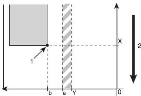
text_image
1 b a Y 0 X 2- Print starting position
- Media feed direction
X (media feeding distance)
Y (print head transferring distance)
a (0mm/8mm: Spitting setting is ON, Off/On Media)
b (5mm to 25mm: Side margin setting)
5.1.3 Side Margin menu
5.1.8 Origin menu
| Setup item Setting | Description | |
| SpittingPerform the spitting operation on Spitting box located on the origin side for every shuttle.·[Enter] key: saves the setting and shifts to the sub menu.5.1.2.1 Spitting Pass Count menu | ||
5.1.2.1 Spitting Pass Count menu
Set the intervals that Print head returns to Spitting boxes when "On" or "On Media" is set in Spitting menu. Print head returns to Spitting box every shuttle per the set number.
NOTE
- If the number of spitting returns is set high, the spitting operation is not done on Spitting box. Therefore there is a higher chance of nozzle clogging when printing for a long time. In such a case, print quality cannot be guaranteed.
| Setup item Setting | Description | |
| ReturnCount <1 time> to 999 | times Set the spitting return count. | |
| — • [Enter] key: | saves the setting and shifts to the previous menu.• [Cancel] key: cancels the setting and shifts to the previous menu.5.1.2 Spitting menu | |
Example of spitting operation
| Spitting setting Return Count setting Operation | ||
| On 1 time Perform the spitting operation on Spitting box every timePrint head returns to the origin position.Spitting operation is not performed over the media. | ||
| On | 5 times | Performs the spitting operation on Spitting box on the origin side every five times Print head returns to the origin position.Spitting operation is not performed over the media. |
| On Media | 1 time | Performs the spitting operation on Spitting box on the origin side every time Print head returns to the origin position.Perform the spitting operation on Spitting box every time Print head returns to the origin position. |
| On Media | 5 times | Performs the spitting operation on Spitting box on the origin side every five times Print head returns to the origin position.Perform the spitting operation on Spitting box every time Print head returns to the origin position. |
| Off — Spitting is not performed on Spitting box or the media. | ||
5.1.3 Side Margin menu
Set up the right and left margins (side margins) while printing.
NOTE
- When the Spitting menu is set to "On Media", the maximum printable media width becomes 16mm shorter.
Therefore, the side margins become the value that you have set in Side Margin menu +8mm.
5.1.2 Spitting menu
- The right side margin will be the following sum depending on the setting.
Y of Origin menu + 8mm (when the spitting is set to On Media) + Value set in Side Margin menu.
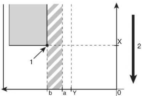
text_image
1 b a Y 0 X 2- Print starting position
- Media feed direction
X (media feeding distance)
Y (print head transferring distance)
a (0mm/8mm: Spitting setting is ON, Off/On Media)
b (5mm to 25mm: Side margin setting)
5.1.2 Spitting menu
5.1.8 Origin menu
| Setup item Setting | Description | |
| Side Margin <5mm> to 25mm | Set the side margins. | |
| — • [Enter] key: | saves the setting and shifts to the previous menu.• [Cancel] key: cancels the setting and shifts to the previous menu.187 5.1 Setup menu |
5.1.4 Media Set menu
Sets whether to detect the media width and edge while initializing the media.
NOTE
- When Media Detection menu is set to "Off", set the media width of the current media in Media Width menu.
5.1.5 Media Width menu
- When the the media detection is set to "Off", the media cannot be cut automatically.
| Setup item Setting | Description | |
| Init. Off The media will not be | detected. | |
| Top&Width Detect the media width and edge while initializing the media. | ||
| Detect the media width while initializing the media. | ||
| —• [Enter] key: saves the setting and shifts to the previous menu.• [Cancel] key: cancels the setting and shifts to the previous menu.5.1 Setup menu | ||
5.1.5 Media Width menu
Specifies the media width between the loading mark and the left end of the media if media detection is not performed during media initialization.
(1) Media Width menu
Displays the detected media width if media detection is performed during media initialization.
(2) MediaWidth menu
For media detection settings, refer to the following.
5.1.4 Media Set menu
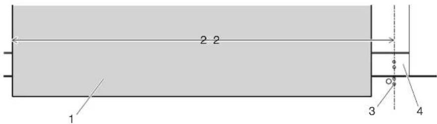
text_image
2 2 1 3 4| No. | Name |
| 1 | Roll media |
| 2 | Media width (when not using media detection) |
| 3 | Media loading mark |
| 4 | Platen |
NOTE
- When the media is loaded as shown in the illustration and not using media detection, the printer may print on between the right edge of Platen and center of the media. If this happens, adjust the print starting position in Origin menu.
5.1.8 Origin menu
(1) Media Width menu
NOTE
- Setting a larger value than the media width set in the Media Width menu may cause ink to leak on the media or printer.
| Setup item Setting | Description | |
| MediaWidth 210mm to <1000 | mm> to 1,625mm | Set the media width. |
| — • [Enter] key: | saves the setting and shifts to the previous menu.• [Cancel] key: cancels the setting and shifts to the previous menu.5.1.1.1 User Type advanced setup menu |
(2) MediaWidth menu
| Setup item Setting | Description | |
| MediaWidth | **** mm | Display the media width that is detected while initializing. |
| — • [Cancel] key: shifts to the previous menu.5.1 Setup menu | ||
5.1.6 Output Mode menu
Sets the media ejection method after printing.
NOTE
- When the take-up unit is not installed, do not set Output mode to "Take-up". By doing so, the product will be unable to function properly.
- When the Output Mode menu is set to "Take-up", the setting for the Prev. Stick menu is disabled. 5.1.9 Prev. Stick menu (VJ-1638 only)
| Setup item Setting | Description | |
| Output modeSet when not cutting the media automatically after printing.(Set it to Off even when cutting the media manually.)) | ||
5.1.6.1 Ink Dry Time menu
Set the ink drying time.
| Setup item Setting | Description | |
| Ink dry time | <0sec> to 60min | Set the ink drying time. |
| — • [Enter] key: | saves the setting and shifts to the previous menu.• [Cancel] key: cancels the setting and shifts to the previous menu.5.1.6 Output Mode menu |
5.1.7 Method of Cut menu
Sets the media cutting operation after printing.
NOTE
- When the the media detection is set to "Off", the media cannot be cut automatically.
- Some media may not be cut (cannot be cut at all or cannot be cut finely). In such a case, set the "Output Mode menu" to "Off" and cut the media manually.
• 51.16 Output Mode menu
4.4.4 Cutting media manually
| Setup item Setting | Description | |
| Method of Cut Cut once - 2 steps | Cut the media shorter step than Cut once - 3 steps. Suitable for narrow media. | |
| Normal cutting method | ||
| Cut twice - 2 steps Set when the media is not cut with Cut once - 2 steps method. Suitable for narrow media. | ||
| Cut twice - 3 steps Set when the media is not cut with Cut once - 3 steps method. | ||
| — • [Enter] key: saves the setting and shifts to the previous menu.• [Cancel] key: cancels the setting and shifts to the previous menu.5.1 Setup menu | ||
5.1.8 Origin menu
Sets the beginning of printing (origin) of the print data.
Set the menu when reprinting on the margin with changing the printing data position to the printed media.
NOTE
- When Output Mode menu is set to "Take-up", the set value X (media feeding distance) becomes 0 mm to 15000 mm.
5.1.6 Output Mode menu
- Depending on the set value of the side margin, the maximum set value of Y (print head transferring distance) decreases.
5.1.3 Side Margin menu
| Setup item Setting Description | |
| Origin • X (media feeding distance):-15000 mm to 15000 mm• Y (print head transferring distance):0mm to 1,405mm | Change Print head position and media feeding distance with the following keys.• [+] key: increases the setting value.• [-] key: decreases the setting value.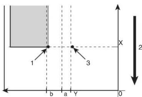 1. Print starting position2. Media feed direction3. Setting position of "Origin"X (media feeding distance)Y (print head transferring distance)a (0mm/8mm: Spitting setting is ON, Off/On Media)b (5mm to 25mm: Side margin setting)NOTEThe right side margin will be the following sum depending on the setting.Y of Origin menu + 8mm (when the spitting is set to On Media) + Value set in Side Margin menu.5.1.2 Spitting menu5.1.3 Side Margin menu• [Enter] key:"Moving Origin Pos." is displayed on Operation panel and Print head moves to the starting position.The following content is displayed on Operation panel. 1. Print starting position2. Media feed direction3. Setting position of "Origin"X (media feeding distance)Y (print head transferring distance)a (0mm/8mm: Spitting setting is ON, Off/On Media)b (5mm to 25mm: Side margin setting)NOTEThe right side margin will be the following sum depending on the setting.Y of Origin menu + 8mm (when the spitting is set to On Media) + Value set in Side Margin menu.5.1.2 Spitting menu5.1.3 Side Margin menu• [Enter] key:"Moving Origin Pos." is displayed on Operation panel and Print head moves to the starting position.The following content is displayed on Operation panel. |
| Confirm Position -> Enter | • [Enter] key or after a certain period of time:Determines the setting.Print head returns to the original position.Save the setting and shift to the previous menu.5.1 Setup menu |
| — • [Cancel] key: cancels the setting and shifts to the previous menu.5.1 Setup menu | |
NOTE
5.1.9 Prev. Stick menu (VJ-1638 only)
Sets up to prevent media from sticking when printing starts.
NOTE
• This function is not displayed for VJ-1638W.
- When the Output Mode menu is set to "Take-up", the setting for the Prev. Stick menu is disabled. 5.1.6 Output Mode menu
| Setup item Setting | Description | |
| Prev. StickThe stick-prevent operation is not performed. | ||
5.1.10 Standby Heating menu (VJ-1638 only)
Sets the time to preheat Heater while the printer is in the standby mode.
NOTE
• This function is not displayed for VJ-1638W.
| Setup item Setting | Description | |
| Standby Heating | 10 minutes - <60 minutes> | Sets the time to pre-heat Heater.When the preset time has passed, each Heater turns Off. |
| — • [Enter] key: | saves the setting and shifts to the previous menu.• [Cancel] key: cancels the setting and shifts to the previous menu.5.1.1.1 User Type advanced setup menu |
5.1.11 Head Travel menu
Sets up the range that Print head moves while printing.
| Setup item Setting | Description | |
| CR Movement Data Print head | moves the range of the print data width. The printing speed will be improved since the moving range of Print head is optimized. | |
| Machine Print head moves from origin to the maximum printable media width. | ||
| Print head shifts within the media width. | ||
| — • [Enter] key: saves the setting and shifts to the previous menu. • [Cancel] key: cancels the setting and shifts to the previous menu. 5.1 Setup menu | ||
NOTE
- The minimum value for the shift width of Print head is 900mm.
- Note that when the printer is set as "Media width" or "Data width", the shift width of Print head does not become below 900mm, even though the width of the loaded media is below 900mm.
5.1.12 Multi Strike menu
Sets up the overwrite count per line.
| Setup item Setting | Description | |
| Multi Strike <1 time> to 9 times | Set the overwrite | count. |
| — • [Enter] key: | saves the setting and shifts to the previous menu.• [Cancel] key: cancels the setting and shifts to the previous menu.5.1 Setup menu |
5.1.13 Strike Wait menu
Sets up the waiting time while overwrite printing.
NOTE
- When using the media with a narrow width, the media cannot be warmed up adequately, therefore the print quality may not be preserved. In such a case, set up the Strike Wait time while overwrite printing to warm up the media adequately before printing.
| Setup item Setting | Description | |
| Strike Wait <0.0 sec.> to 0.1 sec. | sec. to 5.0 | Sets the overwrite wait time. |
| — • [Enter] key: | saves the setting and shifts to the previous menu.• [Cancel] key: cancels the setting and shifts to the previous menu.5.1 Setup menu |
5.1.14 Slant Check menu
Sets up slanting detection during media loading.
| Setup item Setting | Description | |
| Slant Check Off Slant Check is not performed. | ||
| Slant Check is performed. | ||
| — • [Enter] key: | saves the setting and shifts to the previous menu.• [Cancel] key: cancels the setting and shifts to the previous menu.5.1 Setup menu | |
5.1.15 Auto Cleaning menu
Configure the settings for the auto cleaning operation.
TIP
- The cleaning mode reflects the settings in Operation panel.
6.2.3 Head cleaning
NOTE
- When the head height is set to High, auto cleaning is not performed.
| Setup item Setting | Description | |
| Auto Cleaning WaitingTime Set the value for auto-cleaning in standby mode.5.1.15.1 Idle Auto Cleaning | ||
5.1.15.1 Idle Auto Cleaning
Set the auto cleaning interval for the standby mode.
| Setup item Setting | Description | |
| WaitingTime Off to 10 mins to | <360 mins>to 1440 mins | Sets the time for auto cleaning in WaitingTime mode.Off: Auto cleaning is not performed.Others: Perform the head cleaning selected in Cleaning menu after the setting time has elapsed.6.2.3 Head cleaning |
| — • [Enter] key: | saves the setting and shifts to the previous menu.[Cancel] key: cancels the setting and shifts to the previous menu.5.1.15 Auto Cleaning menu |
5.1.15.2 Printing Mode Auto Cleaning
Set the auto cleaning interval during printing.
| Setup item Setting | Description | |
| PrintingTime | to 5 mins to 180 mins | Selects the time for auto cleaning while printing.Off: Auto cleaning is not performed.Others: Perform the head cleaning selected in the Cleaning menu after the setting time has elapsed.6.2.3 Head cleaning |
| — • [Enter] key: | saves the setting and shifts to the previous menu.[Cancel] key: cancels the setting and shifts to the previous menu.5.1.15 Auto Cleaning menu |
5.1.15.3 Pre-printing Mode Auto Cleaning
Set the value for auto cleaning before printing.
| Setup item Setting | Description | |
| Before PrintThe auto cl | cleaning is not performed. | |
| On • Perform the head cleaning selected in the Cleaning menu before printing.6.2.3 Head cleaning | ||
| — • [Enter] key: | saves the setting and shifts to the previous menu.• [Cancel] key: cancels the setting and shifts to the previous menu.5.1.15 Auto Cleaning menu | |
5.1.16 Ink Status menu
Displays various information of IC chips.
NOTE
- To display various information of IC chips, use genuine ink and S/C cards. If Ink cartridges other than genuine Ink cartridges are used, ink status will not be displayed correctly.
| Setup item Setting | Description | |
| KkCcMmYy | 0 to 100 (unit: %) | The amount of ink remaining in each Ink cartridge of K/C/M/Y is displayed. |
| — • [Cancel] key: shifts to the previous menu.5.1 Setup menu | ||
5.1.17 Roll Length menu
Sets up the roll media length.
| Setup item Setting | Description | |
| Roll mediaRoll Length | is not used. | • [Enter] key: saves the setting and shifts to the previous menu.5.1 Setup menu |
| Roll1 Sets up the roll media length. The set values of the roll media length can be set as "Roll1" to "Roll3".• [Enter] key: saves the setting and shifts to the sub menu.5.1.17.1 Roll Length menu | ||
| Roll2 | ||
| Roll3 | ||
| — • [Cancel] key: cancels the setting and shifts to the previous menu.5.1 Setup menu | ||
5.1.17.1 Roll Length menu
Sets up the roll media length.
NOTE
• After replacing the roll media, set the roll media length again.
If the roll media length is not set, the residual quantity of roll media may not be displayed correctly.
| Setup item Setting | Description | |
| Length 1 m to <30 mm> to 99 | mm Sets the roll media length. | |
| — • [Enter] key: | saves the setting and shifts to the previous menu.• [Cancel] key: cancels the setting and shifts to the previous menu.5.1.17 Roll Length menu |
5.1.18 Exhaust Fan menu
Sets up Exhaust fan operation.
Ventilates the inside of the printer to stabilize the parts performance. It also decreases the contamination by ink mist inside the printer. We recommend that you use Exhaust fan, especially when printing for a long time.
| Setup item Setting | Description | |
| Exhaust fan Off Turn Off Exhaust fan. . | ||
| Start Exhaust fan at Low. | ||
| High Start Exhaust fan at High. | ||
| — • [Enter] key: | saves the setting and shifts to the previous menu.• [Cancel] key: cancels the setting and shifts to the previous menu.5.1 Setup menu | |
5.1.19 Longstore menu
Wash Print head with the cleaning fluid.
NOTE
- Be sure to use the dedicated cleaning fluid.
• (VJ-1638)product number: VJ-MSINK3-CL220, VJ-MSINK3-CL1000
• (VJ-1638W)product number: RJ-FGCLS
| Setup item Setting | Description | |
| Longstore Start | Wash Print head with the cleaning fluid.[Enter] key:Performs head cleaning. | |
| — • [Cancel] key: shifts to the previous menu without Head washing.5.1 Setup menu | ||
5.1.20 CR Maintenance menu
Performs maintenance.
Used in the following cases.
- Cleaning Cleaning wiper
6.2.4 Cleaning Cleaning wiper
- Cleaning circumference of Print head
6.2.5 Cleaning the circumference of Print head
- Replacing Cutter
6.1.4 Replacing Cutter
| Setup item Setting | Description | |
| CR Maintenance Start Performs maintenance. | • [Enter] key:Print head moves to the left.Cleaning wiper rises. | |
| The following content is displayed on Operation panel."End"• [Enter] key:Cleaning wiper returns to the original position.Print head returns to the original position. | ||
| — • [Cancel] key: shifts to the previous menu without maintenance.5.1 Setup menu | ||
5.1.21 Initialization menu
Returns the settings of the printer to default.
| Setup item Setting | Description | |
| Initialization ALL All settings | can be returned to factory default. | |
| User Type The setting of the User Type is returned to factory default. | ||
| Settings other than User Type | The setting other than the User Type is returned to factory default. | |
| — • [Enter] key: | "** Initialing **" is displayed on Operation panel and the printer initializes the setting.• [Cancel] key: shifts to the previous menu without initialization.5.1 Setup menu | |
5.1.22 Life Times menu
Displays the operational life time of each part.
| Setup item Setting | Description | |
| Life Times Head 1 Display the | operational life of each part. | The lifetime of each part is indicated by the asterisks (Maximum 5 asterisks: 100% left).As the part deteriorates, the number of asterisks decreases one by one (20%).The part should be changed when all of the asterisks have disappeared and "Change" is displayed.Contact your local MUTOH dealer to ask for replacing parts. |
| Head 2 | ||
| Pump | ||
| CR Motor | ||
| PF Motor | ||
| — • [Cancel] key: shifts to the previous menu.5.1 Setup menu | ||
NOTE
- When replacing a part that its operational life has ended,
- No charge for replacing within the warranty period or under the contract.
- You are liable for the cost of repairs under conditions other than mentioned above.
- Do not keep using the part which has reached its life span. Problems caused by doing so will not be covered by the warranty.
5.1.23 IP Address menu
Sets the IP address of the printer.
NOTE
- Be sure to set the IP address after consulting the network administrator.
| Setup item Setting | Description | |
| IP Address 000.000.000.000 to | <192.168.001.253> to255.255.255.255 | Change the IP address by operating the following keys.[+] key: increases the setting value.[-] key: decreases the setting value.[Enter] key: changes the setting for the next segment.Save the set values in the 4th segment and returns to the previous menu. |
| — • [Cancel] key: cancels the setting and shifts to the previous menu.5.1 Setup menu | ||
5.1.24 Subnet Mask menu
Sets the subnet mask of the printer.
NOTE
- Be sure to set the subnet mask after consulting the network administrator.
| Setup item Setting | Description | |
| Subnet Mask 000.000.000.000 | to<255.255.255.000> to255.255.255.255 | Change the subnet mask by operating the following keys.• [+] key: increases the setting value.• [-] key: decreases the setting value.• [Enter] key: changes the setting for the next segment.Save the set values in the 4th segment and returns to the previous menu. |
| — • [Cancel] key: cancels the setting and shifts to the previous menu.5.1 Setup menu | ||
5.1.25 Gateway menu
Sets the gateway.
NOTE
- Be sure to set the gateway after consulting the network administrator.
| Setup item Setting | Description | |
| Gateway 000.000.000.000 to | <192.168.001.254> to255.255.255.255 | Change the gateway by operating the following keys.[+] key: increases the setting value.[-] key: decreases the setting value.[Enter] key: changes the setting for the next segment.Save the set values in the 4th segment and returns to the previous menu. |
| — • [Cancel] key: cancels the setting and shifts to the previous menu.5.1 Setup menu | ||
5.2 Test Print Menu
Performs nozzle check of Print head and setup list.
TIP
- Refer to the following for the operation procedure of test print.
3.5 Test print
| Setup item Description | |
| Nozzle Check Perform the nozzle check printing. It is used to check whether there are any clogged heads, or missing/blurred prints.3.5.1 Nozzle check | |
| Mode Print Mode print can be performed. Used to confirm the following printing conditions. • Print quality • Effect • Pre-heater temperature (VJ-1638 only) • Platen heater temperature (VJ-1638 only) • Dryer temperature (VJ-1638 only) • Media feed compensation micro adjustment value 3.5.2 Mode print | |
| Setup List Setup list printing is performed. Used to check the setup item and the user type. 3.5.3 Setup print | |
| Palette Palette printing is performed as a color demonstration. NOTE • When the selected print mode of the user type is Graphics 1 or Graphics 2, Palette menu is not displayed. | |
| — | • [Enter] key: "Printing" is displayed on Operation panel and test printing starts. • [Cancel] key: shifts to the previous menu. 5 Panel setup menu |
5.3 Cleaning menu
Performs head cleaning.
TIP
• Head cleaning can be operated when the printer is Normal.
Refer to the following for operation procedures.
6.2.3 Head cleaning
NOTE
- If the head height is set to High, "Change Head Gap Low" is displayed on Operation panel. Set the head height to Low.
4.2.5.3 When setting the head height to Low
| Setup item Description | |
| Short Discharges smaller amount of ink compared to "Normal".• [Enter] key:"Cleaning **%" is displayed on Operation panel and head cleaning starts.Progress on the Head cleaning is displayed in % on Operation panel. | |
| Normal Select this mode normally.• [Enter] key:"Cleaning **%" is displayed on Operation panel and head cleaning starts.Progress on the Head cleaning is displayed in % on Operation panel. | |
| Long Discharges larger amount of ink compare to "Normal".Used when Print head does not improve by normal head cleaning.• [Enter] key:"Cleaning **%" is displayed on Operation panel and head cleaning starts.Progress on the Head cleaning is displayed in % on Operation panel. | |
| Little Charge Refills a small amount of ink.Charge a small amount of ink when printing is not stable after ink replenishment.3.3 Filling ink• [Enter] key:"Ink Refill **%" is displayed on Operation panel and ink replenishment starts.Progress on the ink replenishment is displayed in % on Operation panel. | |
| Initial ink charge Performs the initial ink charge.Even when using the printer whose ink has already been filled, when you use High-capacity ink pack adapter for the first time, perform this initial ink charge.3.3.5 When using High-capacity ink pack adapter for the first time on the printer whose ink is filled.• [Enter] key:"Ink Refill **%" is displayed on Operation panel and ink replenishment starts.Progress on the ink replenishment is displayed in % on Operation panel. | |
| — • [Cancel] key: shifts to the previous menu.5 Panel setup menu | |
5.4 Menu Option menu
Sets up the contents of the Setup menu.
You can make setup items that you do not normally use invisible.
Switch the setting On (displayed) to Off (undisplayed) using the [<] key or [>] key on Operation panel.
When the setting is On, "*" is displayed on Operation panel.
NOTE
- Even if you select "Off" in the Menu Option menu, you can display the settings temporarily by selecting "Temporary" in the Setup menu.
- For VJ-1638, "Prev. Stick" and "StandbyHeating" are not displayed even for temporary display. 5.1 Setup menu
| Setup item | Setting | Description | |
| (VJ-1638) (VJ-1638W) | |||
| User Type Off Off Sets up | up whether to display the User Type menu. | ||
| Spitting Off Off Sets up | whether to display the Spitting menu. | ||
| Side Margin Off Off Sets up | up whether to display the Side Margin menu. | ||
| Media Initial Off Off Sets up | up whether to display the Media Initial menu. | ||
| MediaWidth Off Off Sets up | up whether to display the Media Width menu. | ||
| Output mode Off Off Sets up | up whether to display the Output Mode menu. | ||
| Method of Cut | Off Off Sets up whether to display the Method of Cut menu. | ||
| Origin | Off Off Sets up whether to display the Origin menu. | ||
| Prev. Stick | Off | Sets up whether to display the Prev. Stick menu. | |
| Standby Heating | Off | Sets up whether to display the StandbyHeating menu. | |
| IHead Travel | Off | Off | Sets up whether to display the IHead Travel menu. |
| Multi Strike Off Off Sets | up whether to display the Multi Strike menu. | ||
| Strike Wait Off Off Sets | up whether to display the Strike Wait menu. | ||
| Slant Check Off Off Sets | up whether to display the Slant Check menu. | ||
| Auto Cleaning Off Off Sets | up whether to display the Auto Cleaning menu. | ||
| Ink Status Off Off Sets up | up whether to display the Ink Status menu. | ||
| Roll Length Off Off Sets | up whether to display the Roll Length menu. | ||
| Exhaust fan Off Off Sets | up whether to display the Exhaust Fan menu. | ||
| Longstore Off Off Sets up | up whether to display the Longstore menu. | ||
| CR Maintenance Off Off Sets | Sets up whether to display the CR Maint. menu. | ||
| Initialization Off Off Sets | up whether to display the Initialization menu. | ||
| Life Times Off Off Sets up | up whether to display the Life Times menu. | ||
| IP Address Off Off Sets up | up whether to display the IP Address menu. | ||
| Subnet Mask Off Off Sets up | up whether to display the Subnet Mask menu. | ||
| Gateway | Off Off Sets up whether to display the Gateway menu. | ||
| ALL On | Displays all items in the Setup menu.·Pressing the [Enter] key displays "*" for all items in the Menu Option menu. | ||
| ALL Off | No items in the Setup menu are displayed.·Pressing the [Enter] key deletes "*" for all items in the Menu Option menu.·Even if you select "ALL Off", you can display the items temporarily by selecting "Temporary" in the Setup menu. | ||
| — • [Cancel] key: saves the setting and shifts to the previous menu.5 Panel setup menu | |||
5.5 Version menu
Displays the versions of the firmware.
| Setup item Setting | Description | |
| Ver. M/C *.**(Main side)/ | *.**(Controller side) | Displays the versions of the firmware of the main side (M) and controller side (C). |
| — • [Cancel] key: shifts to the previous menu.5 Panel setup menu | ||
| Setup item Setting | Description | |
| Version *.** Displays the versions of the firmware. | ||
| — • [Cancel] key: shifts to the previous menu.5 Panel setup menu | ||
5.6 Sleep Mode menu
Sleep mode settings are configured.
When you activate sleep mode, the printer operates as follows.
- All Heaters stop (VJ-1638 only).
- All Lamps turn off except for Power lamp.
• Automatic head cleaning is performed after the time set in the Timer Setting Menu has elapsed.
5.6.1 Timer Setting menu
TIP
- The cleaning mode reflects the settings in Operation panel.
6.2.3 Head cleaning
| Setup item Setting | Description | |
| Sleep Mode | Set Timer | Set the auto cleaning interval of this printer for Sleep Mode.5.6.1 Timer Setting menu |
| Start Activate Sleep Mode | 5.6.2 Sleep Mode Start menu | |
| — • [Cancel] key: shifts to the previous menu.5.1 Setup menu | ||
5.6.1 Timer Setting menu
Set the head cleaning interval of this printer for Sleep Mode.
When more than the set time has passed, Print head is cleaned automatically.
NOTE
- During Sleep Mode, even if the set amount of time has passed, print-head cleaning is not performed under the following circumstances.
- Front cover is open.
- Maintenance cover is open.
• Media loading lever is raised.
• The head height is set to High. - Waste fluid tank is full.
- Ink cartridge is empty.
- Ink cartridge has been removed.
- An ink cartridge other than genuine Ink cartridges is inserted into Cartridge slot, etc.
When the printer returns to a normal state, head cleaning is restarted, and Sleep Mode continues.
7.2 Error messages
- If one of the above conditions occurs during head cleaning, cleaning is stopped.
When the printer returns to a normal state, head cleaning is restarted.
7.2 Error messages
| Setup item Setting | Description | |
| Set Timer 1 hour When the set | time has elapsed, head cleaning starts. | |
| 2 hours | ||
| 3 hours | ||
| 4 hours | ||
| 5 hours | ||
| <6 hours> | ||
| 9 hours | ||
| 12 hours | ||
| 18 hours | ||
| 24 hours | ||
| — • [Cancel] key: shifts to the previous menu.5.6 Sleep Mode menu | ||
5.6.2 Sleep Mode Start menu
Activate Sleep Mode
During Sleep Mode, "Restart -> Enter" is displayed on Operation panel.
During Sleep Mode, pressing [Enter] key will return the printer to Normal.
NOTE
- If the printer is under one of the following conditions while shifting to the Sleep Mode, "Don't Start Sleep Mode" is displayed, and will not shift to the Sleep Mode.
- Front cover is open.
- Maintenance cover is open.
• Media loading lever is raised.
• The head height is set to High. - Waste fluid tank is full.
- Ink cartridge is empty.
- Ink cartridge has been removed.
- An ink cartridge other than genuine Ink cartridges is inserted into Cartridge slot, etc.
Activate Sleep Mode again after returning the printer to a normal state.
7.2 Error messages
- If the printer is under one of the conditions above during the Sleep mode, the printer will not return to the Normal condition even after pressing the [Enter] key.
Return the printer to a normal state, and press the [Enter] key to return the printer to normal operation.
7.2 Error messages
| Setup item Setting | Description | |
| Start Start Sleep Mode? • [Enter] key: activates Sleep Mode. | • [Cancel] key: shifts to the previous menu without activating Sleep Mode.5.6 Sleep Mode menu | |
| The following content is displayed on Operation panel.Restart --> Enter• [Enter] key: return the printer to normal operation. | ||
5.7 Display menu
Sets the language and unit displayed on LCD monitor of Operation panel.
| Setup item Setting | Description | |
| Display Language Sets the language used in the menu items displayed on LCD monitor of Operation panel.5.7.1 Language menu | ||
5.7.1 Language menu
Sets the language used in the menu items displayed on LCD monitor of Operation panel.
| Setup item Setting | Description | |
| LanguageDisplays | the menu items in English. | |
| Japanese Displays the menu items in Japanese. | ||
| — • [Enter] key: saves the setting and shifts to the previous menu.• [Cancel] key: cancels the setting and shifts to the previous menu.5.7 Display menu | ||
5.7.2 Temperature menu
Sets the unit of temperature display.
| Setup item Setting | Description | |
| Temperature | Displays the temperature in Celsius [°C]. | |
| Fahrenheit [°F] | Displays the temperature in Fahrenheit [°F]. | |
| — • [Enter] key: | saves the setting and shifts to the previous menu. • [Cancel] key: cancels the setting and shifts to the previous menu. 5.7 Display menu | |
5.7.3 Length menu
Sets the unit to display the length.
| Setup item Setting | Description | |
| LengthDisplays the length in millimeters (mm). | ||
| inch Displays the length in inches (inch). | ||
| — • [Enter] key: saves the setting and shifts to the previous menu.• [Cancel] key: cancels the setting and shifts to the previous menu.5.7 Display menu | ||
6 Maintenance
This chapter describes daily maintenance of the printer.
6.1 Replacing consumable components
This section describes when and how to replace Ink cartridges (or ink packs), roll media and Flushing-box sponges.
6.1.1 Replacing Ink cartridges
This section describes when to replace Ink cartridges.
(1) Replacement time
a. When "[*****] Ink Low" is displayed on Operation panel
- This message is displayed when there is a small amount of ink remaining in Ink cartridge.
• The alarm buzzer sounds.
To stop the buzzer, press the [Enter] key on Operation panel. - Replace with the new Ink cartridge.
b. When "[*****] Ink End" is displayed on Operation panel
- This message is displayed when there is no ink remaining in Ink cartridge.
• The alarm buzzer sounds.
To stop the buzzer, press the [Enter] key on Operation panel. - Immediately replace it with the new Ink cartridge.
NOTE
- [*****] in the messages for ink cartridge replacement indicates the color that is almost empty or runs out, using the following characters.
• K: Black (Slot K1)
• k: Black (Slot K2)
• C: Cyan (Slot C1)
• C: Cyan (Slot C2)
• M: Magenta (Slot M1)
• m: Magenta (Slot M2)
• Y: Yellow (Slot Y1)
• y: Yellow (Slot Y2)
- When all of the ink is consumed, [ALL] Ink End is displayed.
- Do not insert or remove Ink cartridge except at the time of replacement.
Inserting or removing Ink cartridge mixes air into Ink tube, and failures such as nozzle clogging trouble may occur.
- If "Ink End" is displayed, you cannot print until inserting the new Ink cartridge.
- If there is no Ink cartridge for replacement at hand, leave the empty Ink cartridge inserted in the printer.
Leaving the printer with Ink cartridge removed may result in clogging of Print head.
(2) Type
Our genuine Ink cartridges and Ink packs that are compatible with the printer are as follows.
| Description Model No. | |
| Ink cartridge K (Black: 220 ml) VJ-MSINK3A-BK220 | |
| Ink cartridge K (Black: 440ml) VJ-MSINK3A-BK440 | |
| Ink cartridge K (Black: 1,000ml) VJ-MSINK3A-BK1000 | |
| Ink cartridge C (Cyan: 220 ml) VJ-MSINK3A-CY220 | |
| Ink cartridge C (Cyan: 440ml) VJ-MSINK3A-CY440 | |
| Ink cartridge C (Cyan: 1,000ml) VJ-MSINK3A-CY1000 | |
| Ink cartridge M (Magenta: 220 ml) VJ-MSINK3A-MA220 | |
| Ink cartridge M (Magenta: 440ml) VJ-MSINK3A-MA440 | |
| Ink cartridge M (Magenta: 1,000ml) VJ-MSINK3A-MA1000 | |
| Ink cartridge Y (Yellow: 220 ml) VJ-MSINK3A-YE220 | |
| Ink cartridge Y (Yellow: 440ml) VJ-MSINK3A-YE440 | |
| Ink cartridge Y (Yellow: 1,000ml) | VJ-MSINK3A-YE1000 |
| Description Model No. | |
| Ink cartridge K (Black: 220 ml) RJ-FGINK-BK2 | |
| Ink cartridge C (Cyan: 220 ml) RJ-FGINK-CY2 | |
| Ink cartridge M (Magenta: 220 ml) RJ-FGINK-MA2 | |
| Ink cartridge Y (Yellow: 220 ml) RJ-FGINK-YE2 |
NOTE
• To use 1000ml Ink packs, High-capacity ink pack adapter (option) is required.
For details on High-capacity ink pack adapter, contact your local MUTOH dealer.
- Use genuine Ink cartridges for replacement.
This printer is designed to use genuine Ink cartridges and Ink packs.
If you use an ink bag that is not a product of the original manufacturer,
- Printing might become blurred, or the end of the ink in the pack might not be detected correctly.
- Any problems caused by using an ink bag other than those recommended above will not be covered by the warranty, and repair expenses will be paid by the customer.
(3) Replacing steps
Follow the procedure below to replace Ink cartridges and High-capacity ink pack adapters.

CAUTION
- Before operation, make sure to read the Material Safety Data Sheet (MSDS).
- When handling Ink cartridges or Ink packs, pay attention so that ink does not come into contact with your eyes or skin.
If ink gets into your eyes or sticks to your skin, immediately wash it off with water.
Failing to do so might cause irritation or light inflammation of eyes.
In case of any abnormality, consult a physician immediately.
- Do not disassemble Ink cartridges or Ink packs.
If disassembled, ink might come into contact with your eyes or skin.
NOTE
- Do not use the Ink cartridge(s) you have inserted into Ink cartridge slot(s) for other printers. The Ink cartridge(s) will not be used again.
- Do not shake Ink cartridges or Ink packs strongly. Doing so may cause ink leakage.
- Do not disassemble Ink cartridges. A disassembled Ink cartridge or Ink packs cannot be used.
- When the Ink cartridge or Ink pack is moved from a cold place to a warm place, leave it for 3 hours or more in the new printing environment before printing.
- Do not refill an ink cartridge or ink pack with ink. It may result in abnormal printing.
- Insert or remove Ink cartridge and High-capacity ink pack adapter at the time of replacement only. Otherwise, it may result in incorrect printing.
(1) Replacing 220ml and 440ml Ink cartridges
NOTE
440ml Ink cartridges are not compatible with VJ-1638W.
- Confirm that the printer is turned ON.
NOTE
- Do not replace Ink cartridges when the printer is turned OFF. The remaining ink may not be detected correctly, causing abnormal printing.
- Remove Ink cartridge that you want to replace from Slot.
a. For 220ml Ink cartridges

text_image
Technical diagram showing two views of a mechanical device with labeled components and directional arrows indicating movement or assembly.| No. | Name |
| 1 | Ink cartridge |
| 2 | Ink cartridge slots |
b. For 440ml Ink cartridges
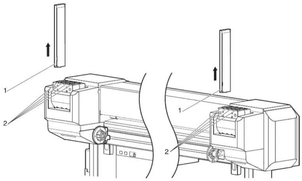
text_image
Technical diagram showing two views of a mechanical device with labeled components and directional arrows indicating assembly or movement.| No. | Name |
| 1 | Ink cartridge |
| 2 | Ink cartridge slots |
- Take out the new Ink cartridge from the bag.
NOTE
- Open the bag just before attaching Ink cartridge to Ink cartridge slot. Leaving Ink cartridge with the bag open for a long time may result in abnormal printing.
- Do not insert or remove Ink cartridge more than 10 times. If the ink cartridge has been removed/inserted more than 10 times, it cannot be used even though ink remains.
-
Shake new Ink cartridge two to three times gently before inserting it into Ink cartridge slot.
-
Confirm that Operation panel returns to Normal.
NOTE
- If Ink cartridge is replaced during printing, printing resumes.
- Ink cartridge replacement is complete.
(2) Replacing High-capacity ink pack adapter (option)
NOTE
High-capacity ink pack adapters are not compatible with VJ-1638W.
- Confirm that the printer is turned ON.
NOTE
- Do not replace High-capacity ink pack adapters when the printer is turned OFF. The remaining ink may not be detected correctly, causing abnormal printing.
- Remove High-capacity ink pack adapter that you want to replace from Ink cartridge slot.
NOTE
- Put the used Ink packs in a plastic bag, etc, and dispose of it in compliance with local ordinance and instructions of local authorities.
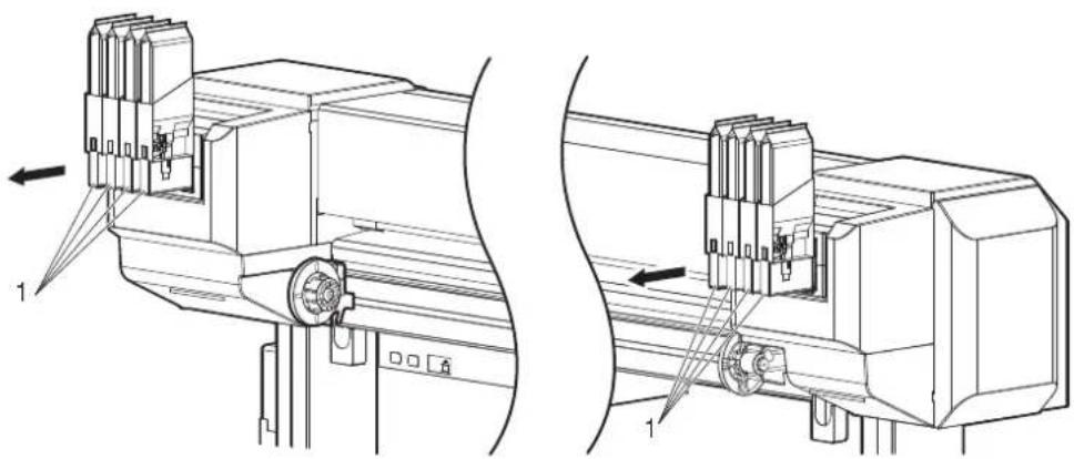
natural_image
Technical line drawing of a mechanical assembly with two views (top and side), showing internal components and directional arrows (no text or symbols)| No. | Name |
| 1 | High-capacity ink pack adapter |
NOTE
- Do not remove only Ink pack while High-capacity ink pack adapter is installed on the printer. The information of the remaining IC chip card will be rewritten and Ink pack will not be usable.
- Take out the new Ink pack from the bag.
NOTE
- Open the bag just before attaching Ink pack to High-capacity ink pack adapter. Leaving Ink pack with the bag open for a long time may result in abnormal printing.
- Do not insert or remove High capacity pack adapter more than 6 times. If High-capacity ink pack adapter is inserted/removed more than 6 times, Connector rubber will require replacement.
- Install Ink pack and IC chip card to High-capacity ink pack adapter.
NOTE
- To install/remove Ink pack or IC chip to/from High-capacity ink pack adapter, refer to the operation manual included with High-capacity ink pack adapter.
- Shake the High-capacity ink pack adapter gently 2 to 3 times and insert it into Ink cartridge slot.
NOTE
- Make sure that Ink pack and IC chip are installed on High-capacity ink pack adapter before inserting it into Ink cartridge slot. If High-capacity ink pack adapter is inserted into Ink cartridge slot without Ink pack, the remaining information will be rewritten and the Ink pack will not be usable.
- Insert High-capacity ink pack adapters all the way in Ink cartridge slots.
- Confirm that Operation panel returns to Normal.
NOTE
- Printing resumes when High-capacity ink pack adapter is replaced during printing.
• High-capacity ink pack adapter replacement is complete.

CAUTION
In the following cases, make sure to perform the initial ink charge from the Cleaning menu after installing High-capacity ink pack adapter.
- When installing High-capacity ink pack adapter for the first time on the printer whose ink is filled
• After using High-capacity ink pack adapters and replacing them with new ones If the printer is used without the initial ink charge, the air inside High-capacity pack adapter goes into Ink Tubes, which may cause nozzle clogging.
5.3 Cleaning menu
6.1.2 Replacing Roll Media
This section describes when and how to replace the roll media.
(1) Replacement time
Replace the roll media when the following situation occurs.
a. When the roll media loaded in the printer runs out
- "End Of Roll" is displayed on Operation panel.
- If media runs out during printing, the printer stops printing.
b. When you want to change the media type to use
(2) Type
TIP
- For types and details of the roll media, refer to "8.3 Options/Supply list".
(3) Replacing steps
Follow the procedure below to replace the roll media.
- If the printer is turned ON, confirm that operation such as printing is not in progress.
- Raise Media loading lever.

natural_image
Technical line drawing of a mechanical device with no visible text or symbols| No. | Name |
| 1 | Media loading lever |
- Turn Flanges of Roll media holder and take up the roll media.
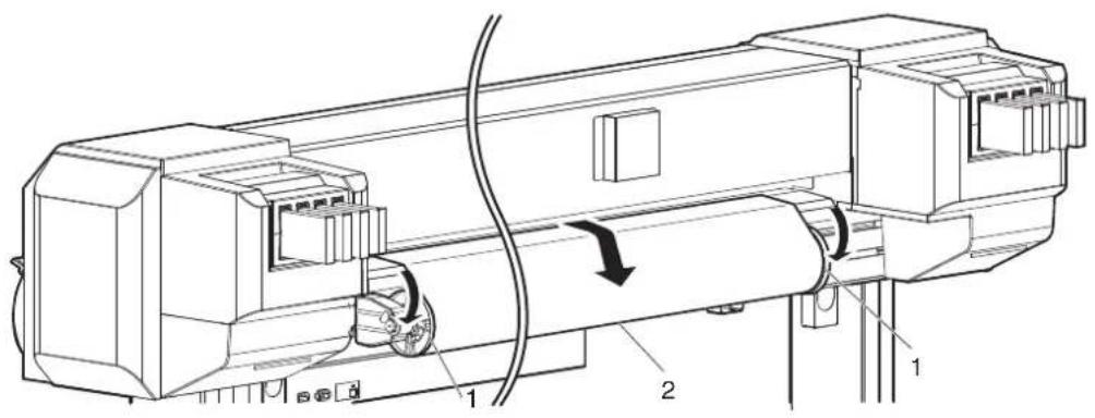
text_image
Technical diagram of a mechanical device with labeled components and directional arrows indicating motion or flow.| No. | Name |
| 1 | Roll media holder |
| 2 | Roll media |
- Loosen Fixing lever of Right roll media holder and remove the roll media from Roll media holder.
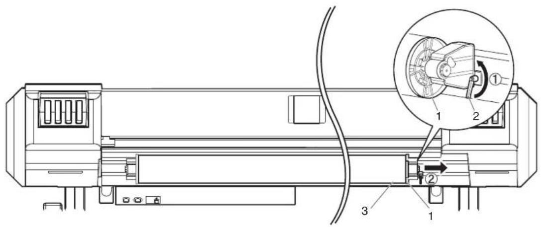
text_image
Technical diagram of a mechanical device with labeled parts and an inset showing a close-up of a mechanical component.| No. | Name |
| 1 | Roll media holder (Right) |
| 2 | Fixing lever |
| 3 | Roll media |
- Take the same procedure as in Step 4, remove the roll media from Roll media holder (left).
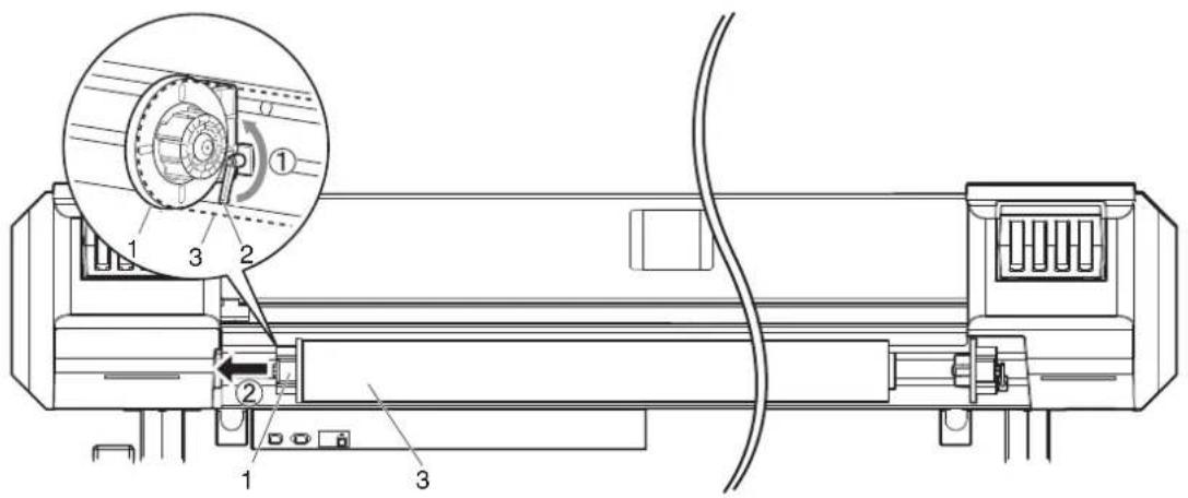
text_image
Technical diagram of a device with numbered components and an inset close-up view highlighting a mechanical component.| No. | Name |
| 1 | Roll media holder (Left) |
| 2 | Fixing lever |
| 3 | Roll media |
- To load another roll media, refer to the following.
TIP
- For loading the roll media, refer to "3.4 Loading media".
- For storing the roll media not in use, refer to "4.2.3 Precaution on storing media".
• The procedure for replacing the roll media is complete.
6.1.3 Replacing Flushing box sponges
This section explains how to replace Flushing-box sponges.
NOTE
Make sure to install Flushing-box sponges in the printer. Flushing-box sponges are an essential part to make printing consistent.
(1) Replacement time
Replace Flushing-box sponges in the following situations.
- When ink clumps have accumulated on Flushing-box sponges beyond Flushing-box frame

| No. | Name |
| 1 | Ink clump |
| 2 | Flushing-box frame |
(2) Type
TIP
- For types and details of Flushing-box sponge, refer to "8.3 Options/Supply list".
(3) Replacing steps
Follow the steps below to replace Flushing-box sponges.
-
If the printer is turned ON, make sure the following.
-
Printing or other operations are not in progress.
• Operation panel display is Normal. -
Display the CR Maintenance menu on Operation panel.
a. Press the [Menu] key on Operation panel.
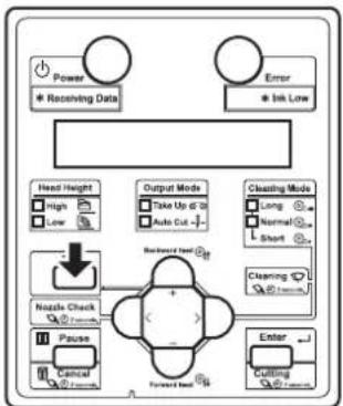
flowchart
graph TD
    A["Power"] --> B["* Receiving Data"]
    C["Error"] --> D["* Ink Low"]
    E["Head Height"] --> F["High"]
    E --> G["Low"]
    H["Output Mode"] --> I["Take Up & 20"]
    H --> J["Auto Cut -"]
    K["Cleaning Mode"] --> L["Long"]
    K --> M["Normal"]
    K --> N["Short"]
    O["Nzzle Check"] --> P["+"]
    Q["Pause"] --> R["-"]
    S["Cancel"] --> T["Forward Lead"]
    U["Enter"] --> V["Cutting"]
    W["Backward Lead"] --> X["+"]
    Y["Forward Lead"] --> Z["-"]
- "Menu1: Setup>" is displayed on Operation panel.
• Operation panel shifts to the Setup menu display.
b. Press the [>] key on Operation panel.
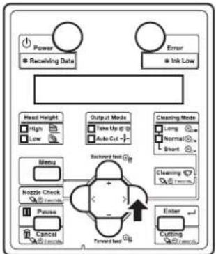
flowchart
graph TD
    A["Power"] --> B["* Receiving Data"]
    C["Error"] --> D["* Ink Low"]
    E["Menu"] --> F["Nozzle Check"]
    G["Pause"] --> H["Cancel"]
    I["Forward Event"] --> J["Enter"]
    K["Backward Event"] --> L["Output Mode"]
    M["Cleaning Mode"] --> N["Take Up @ 0"]
    O["Cleaning Mode"] --> P["Auto Cut -"]
    Q["Warning Event"] --> R["->"]
    S["OK"] --> T["->"]
- "Set1: User Type" is displayed on Operation panel.
c. Press the [+] key or [-] key on Operation panel to select "Set 20: CR Maintenance".
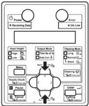
flowchart
graph TD
    A["Power"] --> B["Receiving Data"]
    C["Error"] --> D["Irk Low"]
    E["Head Height"] --> F["High"]
    E --> G["Low"]
    H["Menu"] --> I["Nzzle Check"]
    H --> J["Pause"]
    H --> K["Control"]
    L["Output Mode"] --> M["Take Up of 10"]
    L --> N["Make Cut"]
    O["Cleaning Mode"] --> P["Long"]
    O --> Q["Normal"]
    O --> R["Short"]
    S["Enter"] --> T["Cutting"]
    U["Start"] --> V["End"]
d. Press the [Enter] key on Operation panel.
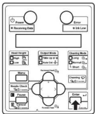
flowchart
graph TD
    A["Power"] --> B["Receiving Data"]
    C["Error"] --> D["Ink Low"]
    E["Head Height"] --> F["High"]
    E --> G["Low"]
    H["Output Mode"] --> I["Take Up to 30"]
    H --> J["Auto Cut"]
    K["Cleaning Mode"] --> L["Long"]
    K --> M["Normal"]
    K --> N["Short"]
    O["Menu"] --> P["Nestle Check"]
    O --> Q["Pause"]
    O --> R["Cancel"]
    S["Forward Set"] --> T["Enter"]
    U["Backward Shift"] --> V["+"]
    W["1.2mm"] --> X["+"]
- "CR Mainte.: Start" is displayed on Operation panel.
• The display enters the CR Maintenance menu.
5.1.20 CR Maintenance menu
- Press the [Enter] key on Operation panel.
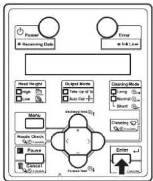
flowchart
graph TD
    A["Power"] --> B["Receiving Data"]
    C["Error"] --> D["Ink Low"]
    E["Head Height"] --> F["High"]
    E --> G["Low"]
    H["Output Mode"] --> I["Take Up of 3"]
    H --> J["Auto Cut"]
    K["Cleaning Mode"] --> L["Long"]
    K --> M["Normal"]
    K --> N["Short"]
    O["Menu"] --> P["Nozzle Check"]
    Q["Pause"] --> R["Cancel"]
    S["Forward Test"] --> T["Enter"]
    U["Forward Test"] --> V["Enter"]
- Maintenance starts.
- Print head moves to the left.
-
"CR Mainte.: End" is displayed on Operation panel.
-
Open Front cover.
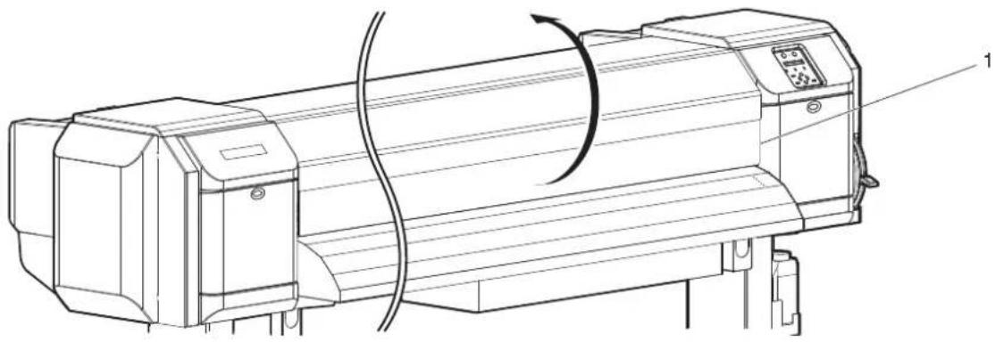
natural_image
Technical line drawing of a cylindrical industrial machine with attached control panel and base mount (no text or symbols)| No. | Name |
| 1 | Front cover |
- Replace Flushing-box sponge in a short time.
Leaving Print head at the replacement position may result in clogging of Print head.
- Lift Flushing-box sponge tab and unhook. Then, remove Flushing-box sponge.
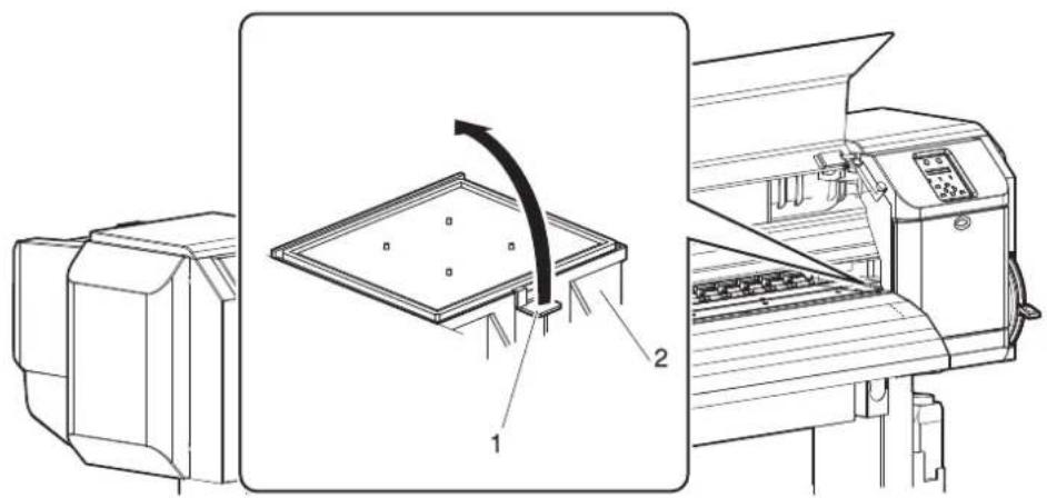
text_image
Technical diagram showing a machine with labeled components and a directional arrow indicating rotation or movement.| No. | Name |
| 1 | Flushing-box sponge tab |
| 2 | Flushing boxes |
CAUTION
- Do not spill waste fluid when replacing Flushing-box sponges. If waste fluid comes into contact with Grid roller, it may damage its surface and affect media feeding.
- Install the new Flushing-box sponge to each Flushing box.
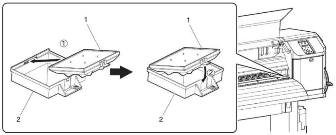
text_image
Technical diagram showing assembly steps of a machine tool, with labeled components and directional arrows indicating process flow.| No. | Name |
| 1 | Flushing-box sponges |
| 2 | Flushing boxes |
- Close Front cover.
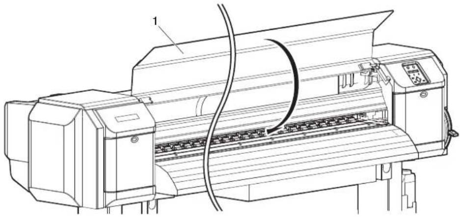
natural_image
Technical line drawing of a printer with paper feed and control panel (no text or symbols)| No. | Name |
| 1 | Front cover |
- Press the [Enter] key on Operation panel.
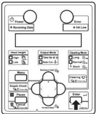
flowchart
graph TD
    A["Power"] --> B["* Receiving Data"]
    C["Error"] --> D["* Ink Low"]
    E["Head Height"] --> F["High"]
    E --> G["Low"]
    H["Output Mode"] --> I["Take Up @ 20"]
    H --> J["Auto Cut -"]
    K["Cleaning Mode"] --> L["Long"]
    K --> M["Normal"]
    K --> N["Short"]
    O["Menu"] --> P["Nzzle Check"]
    O --> Q["Pause"]
    O --> R["Cancel"]
    O --> S["Forward Entry"]
    T["Enter"] --> U["7-10mm"]
    V["Backward Entry"] --> W["+"]
    X["Forward Entry"] --> Y["+"]
- Print head returns to its original position.
-
"CR Mainte.: Start" is displayed on Operation panel.
-
Press the [Menu] key on Operation panel.

flowchart
graph TD
    A["Power<br>* Receiving Date"] --> B["Head Height<br>High Low"]
    C["Error<br>* Ink Low"] --> D["Output Mode<br>Take Up @ 10<br>Auto Cut -"]
    E["Nozzle Check<br>Pause Cancel"] --> F["Backward feed G1"]
    F --> G["Forward feed G2"]
    G --> H["Enter<br>Cutting"]
    I["Cleaning Mode<br>Long Normal Short"] --> J["Cleaning Mode<br>Normal Short"]
• The printer enters Normal.
- Flushing-box sponge replacement is complete.
6.1.4 Replacing Cutter
This section describes when and how to replace Cutter.
(1) Replacement time
Replace Cutter when the following situation occurs.
a. When the media is not cut smoothly
b. When the cut surface is feathered, etc
(2) Type
Our genuine Cutter that is compatible with the printer is as follows.
| Description Model No. | |
| Cutter replacement blade VJ-CB |
(3) Replacing steps
Follow the procedure below to replace Cutter.
TIP
• The illustrations used in this section are those of VJ-1638.
-
If the printer is turned ON, make sure the following.
-
Printing or other operations are not in progress.
• Operation panel display is Normal. -
Display the CR Maintenance menu on Operation panel.
a. Press the [Menu] key on Operation panel.

flowchart
graph TD
    A["Power"] --> B["Receiving Data"]
    C["Error"] --> D["Ink Low"]
    E["Head Height"] --> F["High"]
    E --> G["Low"]
    H["Output Mode"] --> I["Take Up at 10"]
    H --> J["Auto Cut"]
    K["Cleaning Mode"] --> L["Long"]
    K --> M["Normal"]
    K --> N["Short"]
    O["Nestle Check"] --> P["+"]
    Q["Pause"] --> R["Cancel"]
    S["Forward Test"] --> T["Enter"]
    U["Cutting"] --> V["Start"]
- "Menu1: Setup>" is displayed on Operation panel.
• Operation panel shifts to the Setup menu display.
b. Press the [>] key on Operation panel.
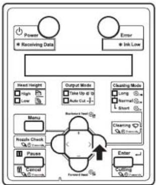
flowchart
graph TD
    A["Power"] --> B["Receiving Data"]
    C["Error"] --> D["Ink Low"]
    E["Head Height"] --> F["High"]
    E --> G["Low"]
    H["Menu"] --> I["Nzzle Check"]
    H --> J["Pause"]
    H --> K["Cancel"]
    L["Output Mode"] --> M["Take Up @ 20"]
    L --> N["Auto Cut"]
    O["Cleaning Mode"] --> P["Long"]
    O --> Q["Normal"]
    O --> R["Short"]
    S["Forward Test"] --> T["Enter"]
    U["Cutting"] --> V["7.7mm"]
    W["Backward Test"] --> X["+"]
    Y["Forward Test"] --> Z["-"]
- "Set1: User Type" is displayed on Operation panel.
c. Press the [+] key or [-] key on Operation panel to select "Set 20: CR Maintenance".
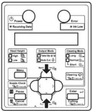
flowchart
graph TD
    A["Power\n* Receiving Data"] --> B["Error\n* Ink Low"]
    C["Head Height\nHigh\nLow"] --> D["Menu\nNozzle Check\nPause\nCancel"] --> E["Output Mode\nTake Up @ 2\nTake Cut -"]
    F["Cleaning Mode\nLong\nNormal\nShort"] --> G["Cleaning\nCutting"]
    H["Enter"] --> I["Final Output"]
    J["Start"] --> K["End"]
d. Press the [Enter] key on Operation panel.

flowchart
graph TD
    A["Power"] --> B["* Receiving Data"]
    C["Error"] --> D["* Ink Low"]
    E["Head Height"] --> F["High"]
    E --> G["Low"]
    H["Output Mode"] --> I["Take Up @ 10"]
    H --> J["Auto Cut -"]
    K["Cleaning Mode"] --> L["Long"]
    K --> M["Normal"]
    K --> N["Short"]
    O["Menu"] --> P["Nozzle Check"]
    O --> Q["Pause"]
    O --> R["Control"]
    S["Forward Load"] --> T["Enter"]
    U["Backward Load"] --> V["+"]
    W["External Control"] --> X["→"]
- "CR Mainte.: Start" is displayed on Operation panel.
• The display enters the CR Maintenance menu. 5.1.20 CR Maintenance menu
- Press the [Enter] key on Operation panel.

flowchart
graph TD
    A["Power"] --> B["Receiving Data"]
    C["Error"] --> D["Ink Low"]
    E["Head Height"] --> F["High"]
    E --> G["Low"]
    H["Output Mode"] --> I["Take Up to 10"]
    H --> J["Auto Out"]
    K["Cleaning Mode"] --> L["Long"]
    K --> M["Normal"]
    K --> N["Short"]
    O["Menu"] --> P["Nozzle Check"]
    O --> Q["Pause"]
    O --> R["Cancel"]
    S["Forward Test"] --> T["Enter"]
    U["Forward Test"] --> V["7.7mm"]
- Maintenance starts.
- Print head moves to the left of the printer (cutter replacement position).
-
"CR Mainte.: End" is displayed on Operation panel.
-
Open Maintenance cover on the left of the printer.
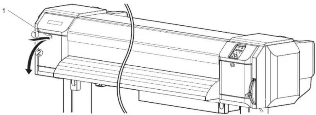
text_image
Technical line drawing of a printer with labeled components and directional arrows indicating motion or assembly.| No. | Name |
| 1 | Maintenance cover |
NOTE
- Replace Cutter in a short time. Leaving Print head at the cutter replacement position may result in clogging of Print head.
- Press the tab of Cutter lightly, turn Cutter holder in the direction as illustrated below.
NOTE
- Do not press the tab of Cutter strongly or suddenly let go of it. There is a spring in Cutter holder and it may fly out.
- Do not push Cutter all the way in. Cutter blade may damage the inside of the printer.
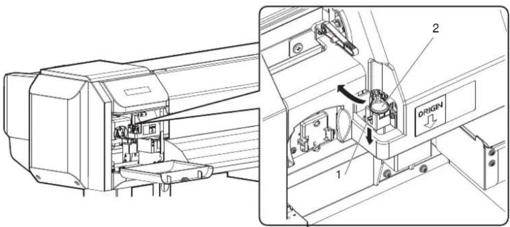
text_image
Technical diagram of an air conditioner unit with labeled components and directional arrows indicating flow or movement.| No. | Name |
| 1 | Cutter holder |
| 2 | Cutter holder lever |
- Remove Cutter.
CAUTION
- Do not touch the blade edge. It may cause an injury.
- Do not touch the cutter blade edge with a hard substance or drop Cutter. Cutter blade may be damaged or chipped.
NOTE
- Used Cutter should be put in a plastic bag, etc, and dispose of it in compliance with local ordinance and instructions of local authorities.

natural_image
Technical line drawing of a mechanical assembly with internal components and a labeled origin (no text or symbols beyond labels)| No. | Name |
| 1 | Razor blade |
- Install a new Cutter as illustrated.
NOTE
- Make sure that the spring in Cutter holder does not fly out while installing.
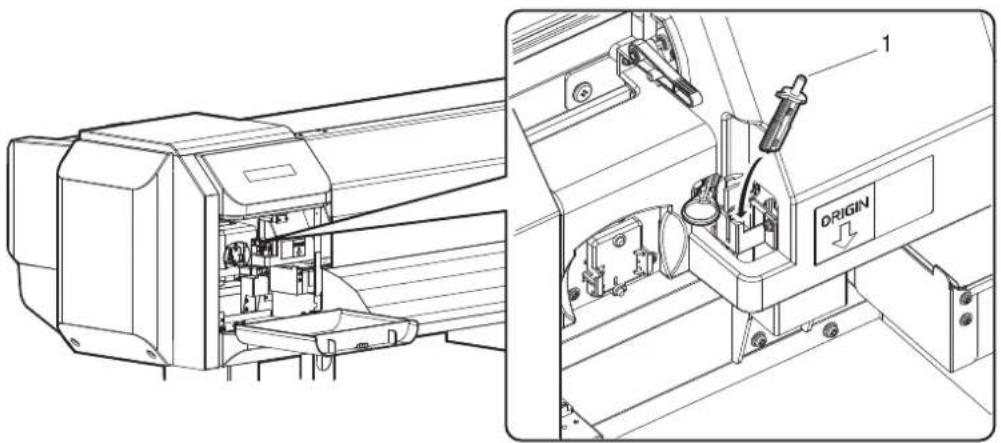
natural_image
Technical line drawing of an industrial machine with internal components and a labeled origin (no text or symbols beyond labels)| No. | Name |
| 1 | Razor blade |
- Press the tab of Cutter lightly, return Cutter holder to its initial position.
NOTE
- Do not press the tab of Cutter strongly or suddenly let go of it. There is a spring in Cutter holder and it may fly out.
- Do not push Cutter all the way in. Cutter blade may damage the inside of the printer.
- Refer to the illustrations below and install Cutter holder correctly. If it is not installed correctly, it may cause an error. If an error occurs, check if Cutter holder is installed correctly.

text_image
Technical diagram of an industrial machine with labeled components and directional arrows indicating flow or movement.| No. | Name |
| 1 | Cutter holder |
| 2 | Cutter holder lever |
- Close Maintenance cover.
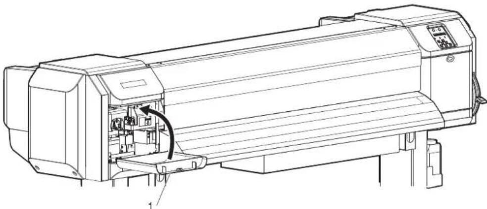
natural_image
Technical line drawing of a printer with internal components and a directional arrow indicating motion (no text or symbols)| No. | Name |
| 1 | Maintenance cover |
- Press the [Enter] key on Operation panel.
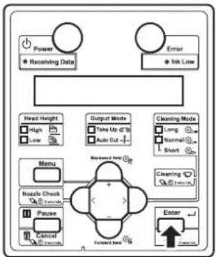
flowchart
graph TD
    A["Power"] --> B["* Receiving Data"]
    C["Error"] --> D["* Ink Low"]
    E["Head Height"] --> F["High"]
    E --> G["Low"]
    H["Menu"] --> I["Nzzle Check"]
    H --> J["Pause"]
    H --> K["Control"]
    L["Output Mode"] --> M["Take Up Of 70"]
    L --> N["Auto Cut"]
    O["Cleaning Mode"] --> P["Long"]
    O --> Q["Normal"]
    O --> R["Short"]
    S["Backward Head"] --> T["Forward Head"]
    U["Enter"] --> V["Forward"]
- Print head returns to its original position.
-
"CR Mainte.: Start" is displayed on Operation panel.
-
Press the [Menu] key on Operation panel.

flowchart
graph TD
    A["Power"] --> B["Receiving Data"]
    C["Error"] --> D["Ink Low"]
    E["Head Height"] --> F["High"]
    E --> G["Low"]
    H["Noise Check"] --> I["Pause"]
    H --> J["Cancel"]
    K["Output Mode"] --> L["Take Up to 30"]
    K --> M["Auto Cut"]
    N["Cleaning Mode"] --> O["Long"]
    N --> P["Normal"]
    N --> Q["Short"]
    R["Forward Test"] --> S["+"]
    T["Enter"] --> U["Coulding"]
    V["Backward Test"] --> W["+"]
• The printer enters Normal.
- Cutter replacement is complete.
6.2 Cleaning the printer
Periodic (every month) cleaning is necessary to use the printer in good condition.

WARNING
- Do not insert or drop metal or flammable objects into the printer through openings such as a vent.
It could lead to an electric shock or fire. - If foreign substances or liquids such as water entered the printer, do not use the printer as it is.
It could lead to an electric shock or fire.
Immediately turn OFF the power switch, disconnect the power plug from the electric socket, and contact your local MUTOH dealer.

CAUTION
- When cleaning the printer, be sure to turn OFF the power and disconnect Power plug.
- Do not use volatile solvents such as thinner, benzene, or alcohol.
These solvents may cause damage to the paint. - Make sure that no moisture enters the printer.
The electric circuit inside the printer may be short-circuited. - Never open covers attached using screws under any circumstances.
This may cause an electric shock or a malfunction.
This section describes how to clean each part of the printer.
6.2.1 Cleaning the outer case
This section describes how to clean the outer case.
Wipe out dust and dirt attached to the outer case by using a soft cloth.
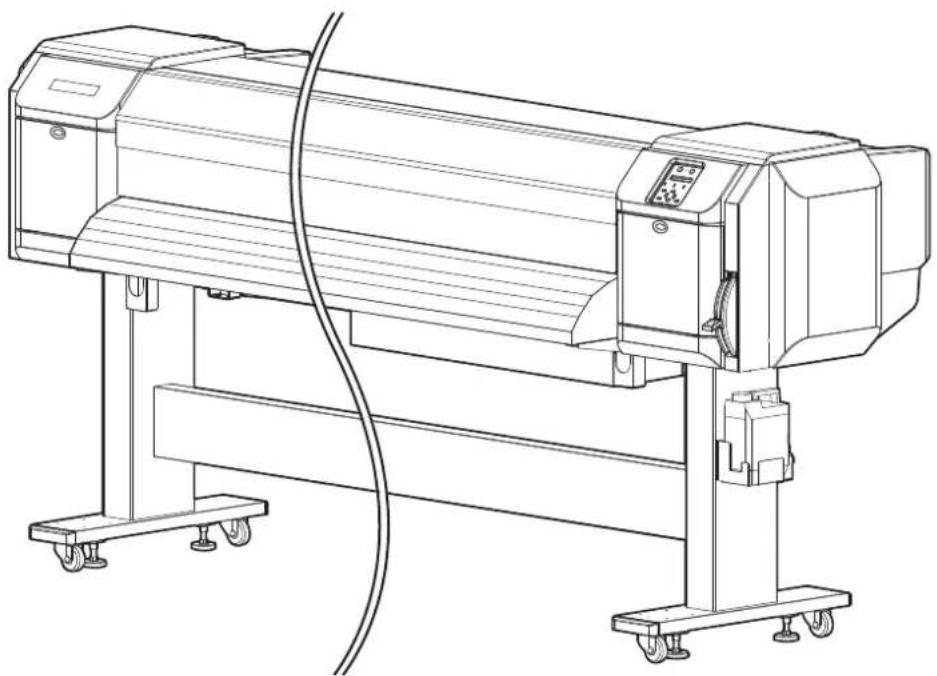
natural_image
Line drawing of a mechanical device with wheels and control panel (no text or symbols)6.2.2 Cleaning the inside of the printer
This section describes how to clean the inside of the printer.
Follow the procedure below.
- Open Front cover.

natural_image
Technical line drawing of a mechanical device with a rotating shaft and control panel (no text or symbols)| No. | Name |
| 1 | Front cover |
- Remove paper powder and dust attached to Pressurizing rollers using a soft brush.
NOTE
- Do not blow paper powder inside the printer using tools such as an air duster. It may cause an abnormal noise from the inside of the printer.
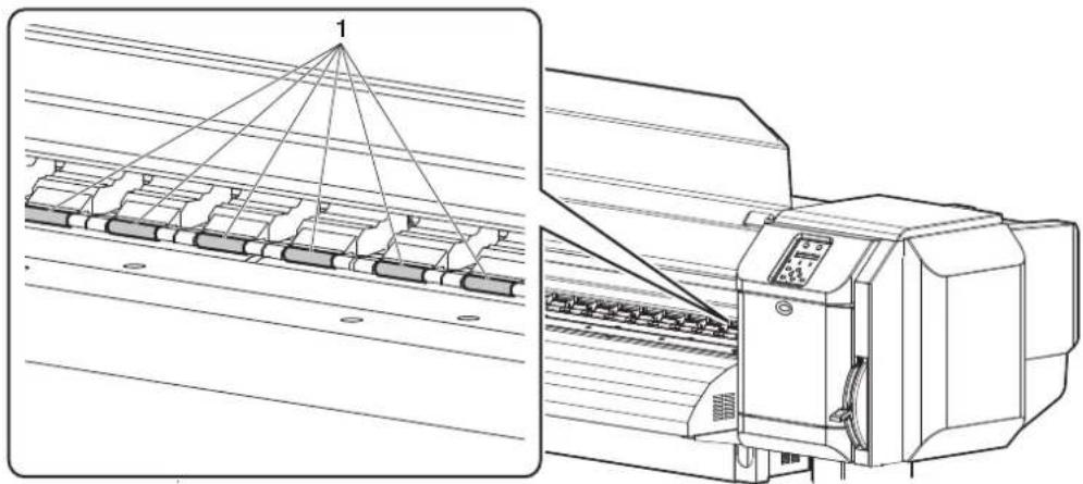
natural_image
Technical line drawing of a printer with a triangular load distribution scheme and its side view (no text or symbols)| No. | Name |
| 1 | Pressurizing rollers |
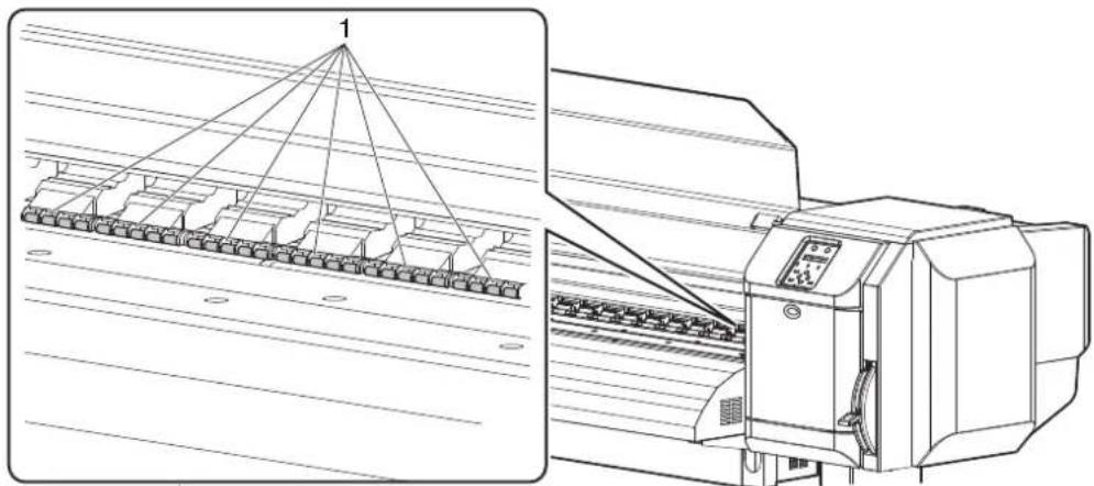
natural_image
Technical line drawing of a textile machine with a triangular roof structure and internal components (no text or symbols)| No. | Name |
| 1 | Pressurizing rollers |
- Apply a damp and tightly squeezed soft cloth to wipe out paper powder and ink attached to Platen and Media guide.
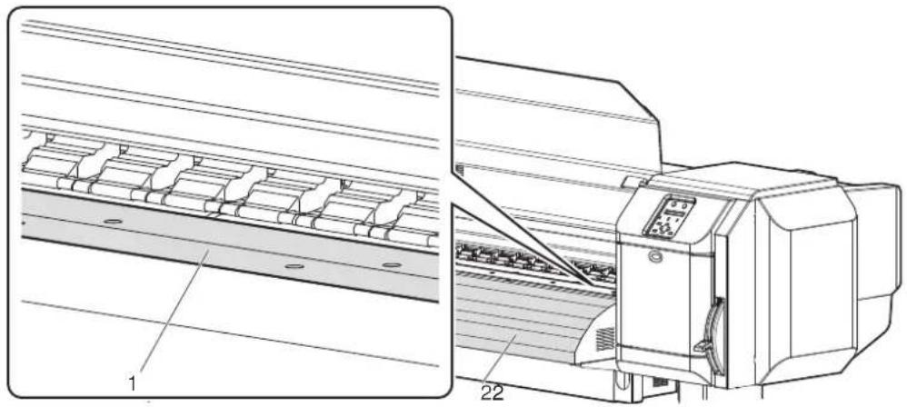
natural_image
Technical line drawing of a printer with internal components and part numbers 1 and 22 (no text or symbols on the diagram itself)| No. Name |
| 1 Platen |
| 2 Media guide |
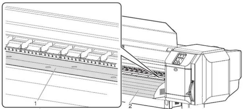
natural_image
Technical line drawing of a mechanical device with labeled components (no text or symbols present)| No. | Name |
| 1 | Platen |
| 2 | Media guide |
- Apply a damp and tightly squeezed soft cloth to wipe off the dirt of the unpainted (silver color) area in the center of Grid roller.
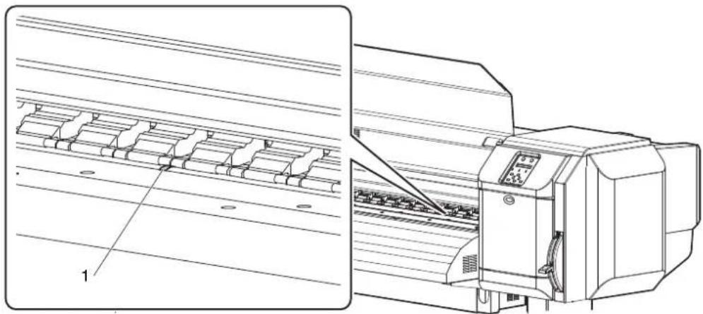
natural_image
Technical line drawing of a printer with internal components and a close-up view of its base (no text or symbols present)| No. | Name |
| 1 | Grid roller |
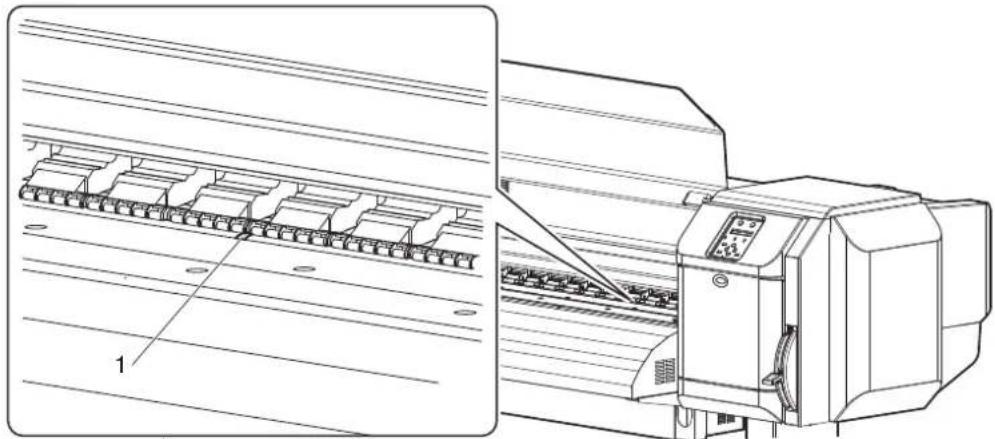
natural_image
Technical line drawing of a printer with internal components and a close-up view of its base panel (no text or symbols present)| No. | Name |
| 1 | Grid roller |
6.2.3 Head cleaning
If printed data is blurred or lacks part of it, clean the print head surface and Nozzles (Head cleaning).
Follow the procedure below to perform Head cleaning.
NOTE
- When not using the printer for a long period (one week or more), perform Head cleaning once a week.
If not performing Head cleaning, Print head is clogged. Doing so will preserve print quality.
- Confirm that Operation panel is Normal.
- Check that Media loading lever is lowered.
- Press the [>] key on Operation panel to select the Cleaning mode.
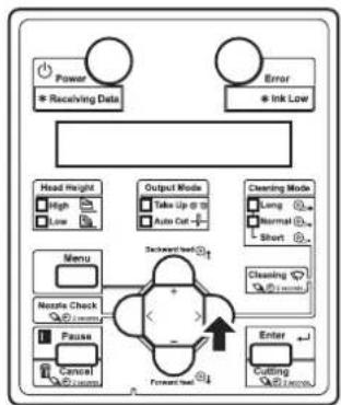
flowchart
graph TD
    A["Power"] --> B["Receiving Data"]
    C["Error"] --> D["Ink Low"]
    E["Head Height"] --> F["High"]
    E --> G["Low"]
    H["Output Mode"] --> I["Take Up @ 10"]
    H --> J["Auto Cut +"]
    K["Clearing Mode"] --> L["Long"]
    K --> M["Normal"]
    K --> N["Short"]
    O["Menu"] --> P["Nestle Check"]
    O --> Q["Pause"]
    O --> R["Cancel"]
    S["Forward Test"] --> T["Enter"]
    U["Cutting"] --> V["Inverter"]
- Press the [Cleaning] key on Operation panel for more than two seconds.

flowchart
graph TD
    A["Power"] --> B["Receiving Data"]
    C["Error"] --> D["Ink Low"]
    E["Head Height"] --> F["High"]
    E --> G["Low"]
    H["Output Mode"] --> I["Take Up at 3"]
    H --> J["Auto Out"]
    K["Cleaning Mode"] --> L["Long"]
    K --> M["Normal"]
    K --> N["Short"]
    O["Menu"] --> P["Nestle Check"]
    O --> Q["Pause"]
    O --> R["Cancel"]
    S["Forward Path"] --> T["Enter"]
    U["Cutting"] --> V["Cutting"]
    W["Reset/End"] --> X["Reset/End"]
- Head cleaning starts.
- "Cleaning **%" is displayed on Operation panel.
• After Head cleaning is complete, Operation panel shifts to Normal.
NOTE
• To perform head cleaning during printing while the head height is set to High, make sure to do the following.
- When "Change Head Gap Low" is displayed on Operation panel, set the head height to Low.
- After head cleaning is complete, "Change Head Gap High" is displayed on Operatino panel. Set the head height to High. After changing the setting, printing starts.
4.2.5 Head height adjustment
- If blurs or lacking parts in printed media do not disappear with one time of Head cleaning, perform Strong cleaning.
- If blurs or lacking parts in printed media do not disappear with several times of Head cleaning, refer to "7 Troubleshooting", and take appropriate measures.
6.2.4 Cleaning Cleaning wiper
This section describes how to clean Cleaning wiper.
(1) Time for cleaning
Once a week, or when blurs or lacking parts appear on printed media after Head cleaning.
(2) Cleaning procedures
Follow the procedure below to clean Cleaning wiper.
NOTE
- Use Cleaning stick to clean Cleaning wiper. For details of Cleaning stick, refer to "8.3 Options/Supply list".
-
If the printer is turned ON, make sure the following.
-
Printing or other operations are not in progress.
• Operation panel display is Normal. -
Display the CR Maintenance menu on Operation panel.
a. Press the [Menu] key on Operation panel.
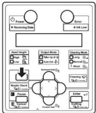
flowchart
graph TD
    A["Power"] --> B["Receiving Data"]
    C["Error"] --> D["Ink Low"]
    E["Head Height"] --> F["High"]
    E --> G["Low"]
    H["Output Mode"] --> I["Take Up to 30"]
    H --> J["Auto Cut"]
    K["Clearing Mode"] --> L["Long"]
    K --> M["Normal"]
    K --> N["Short"]
    O["Nestle Check"] --> P["Forward Set"]
    Q["Pause"] --> R["Control"]
    S["Enter"] --> T["Cutting"]
    U["Backward Check"] --> V["Forward Set"]
- "Menu1: Setup>" is displayed on Operation panel.
- Operation panel shifts to the Setup menu display.
b. Press the [>] key on Operation panel.

flowchart
graph TD
    A["Power"] --> B["Receiving Data"]
    C["Error"] --> D["Ink Low"]
    E["Head Height"] --> F["High"]
    E --> G["Low"]
    H["Output Mode"] --> I["Take Up @ 10"]
    H --> J["Auto Cut"]
    K["Cleaning Mode"] --> L["Long"]
    K --> M["Normal"]
    K --> N["Short"]
    O["Menu"] --> P["Nettle Check"]
    Q["Pause"] --> R["Cancel"]
    S["Forward Path"] --> T["Enter"]
    U["Cutting"] --> V["40% records"]
- "Set1: User Type" is displayed on Operation panel.
c. Press the [+] key or [-] key on Operation panel to select "Set 20: CR Maintenance".
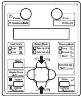
flowchart
graph TD
    A["Power"] --> B["Receiving Data"]
    C["Error"] --> D["Ink Low"]
    E["Head Height"] --> F["High"]
    E --> G["Low"]
    H["Menu"] --> I["Nestle Check"]
    H --> J["Pause"]
    K["Output Mode"] --> L["Take Up at 10"]
    K --> M["Auto Cut"]
    N["Cleaning Mode"] --> O["Long"]
    N --> P["Normal"]
    N --> Q["Short"]
    R["Enter"] --> S["Cutting"]
    R --> T["Cutting"]
d. Press the [Enter] key on Operation panel.

flowchart
graph TD
    A["Power"] --> B["* Receiving Data"]
    C["Error"] --> D["* Ink Low"]
    E["Head Height"] --> F["High"]
    E --> G["Low"]
    H["Menu"] --> I["Nzzle Check"]
    H --> J["Pause"]
    H --> K["Cancel"]
    L["Output Mode"] --> M["Take Up @ 28"]
    L --> N["Auto Cut"]
    O["Cleaning Mode"] --> P["Long"]
    O --> Q["Normal"]
    O --> R["Short"]
    S["Forward Use"] --> T["Enter"]
    U["Backward Use"] --> V["+"]
    W["Forward Use"] --> X["+"]
- "CR Mainte.: Start" is displayed on Operation panel.
- The display enters the CR Maintenance menu.
5.1.20 CR Maintenance menu
- Press the [Enter] key on Operation panel.
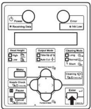
flowchart
graph TD
    A["Power"] --> B["Receiving Data"]
    C["Error"] --> D["Irk Low"]
    E["Head Height"] --> F["High"]
    E --> G["Low"]
    H["Menu"] --> I["Nazole Check"]
    H --> J["Pause"]
    H --> K["Control"]
    L["Output Mode"] --> M["Take Up of 10"]
    L --> N["Auto Cut"]
    O["Cleaning Mode"] --> P["Long"]
    O --> Q["Normal"]
    O --> R["Short"]
    S["Backward Load"] --> T["Forward Load"]
    U["Enter"] --> V["Forward Load"]
- Maintenance starts.
- Print head moves to the left.
- Cleaning wiper rises.
-
"CR Mainte.: End" is displayed on Operation panel.
-
Open Maintenance cover on the right of the printer.

text_image
Technical diagram of a printer with labeled parts and directional arrows indicating motion or movement.| No. | Name |
| 1 | Maintenance cover |

CAUTION
- When cleaning Ceaning wiper,
• do not touch Cleaning wiper and Head cap unit.
Head cleaning may not be performed correctly because of oil from your hands.
- Make sure to use Cleaning stick to wipe Print head. A wet Cleaning stick may cause Print head to clog.
- Do not reuse Cleaning stick.
The attached dust, etc may damage Print head.
- Use Cleaning stick to remove the ink and dust on Cleaning wiper.
a. Front side of Cleaning wiper:
Remove the ink and dust in the horizontal direction.
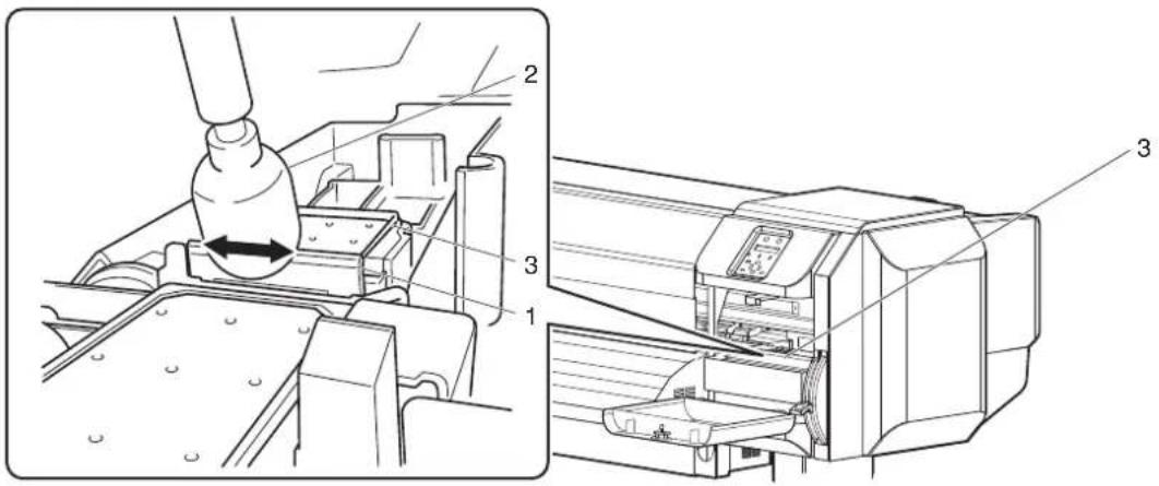
text_image
Technical diagram showing a mechanical assembly with labeled parts, including a tool and a printer.| No. | Name |
| 1 | Cleaning wiper |
| 2 | Cleaning stick |
| 3 | Head cap unit |
b. Cleaning wiper back side:
Remove the ink and dust in the upper direction.
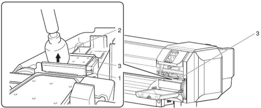
text_image
Technical diagram showing a printer assembly process with labeled parts 1, 2, and 3| No. | Name |
| 1 | Cleaning wiper |
| 2 | Cleaning stick |
| 3 | Head cap unit |
- Close the right maintenance cover.
- Close the cover firmly until it is locked.

natural_image
Technical line drawing of a printer with cable and control panel (no text or symbols)| No. | Name |
| 1 | Maintenance cover |
- Press the [Enter] key on Operation panel.

flowchart
graph TD
    A["Power"] --> B["Receiving Data"]
    C["Error"] --> D["Ink Low"]
    E["Head Height"] --> F["High"]
    E --> G["Low"]
    H["Output Mode"] --> I["Take Up @ 0"]
    H --> J["Auto Cut +"]
    K["Cleaning Mode"] --> L["Long"]
    K --> M["Normal"]
    K --> N["Short"]
    O["Menu"] --> P["Nextate Check"]
    O --> Q["Pause"]
    O --> R["Cancel"]
    S["Forward Path"] --> T["Enter"]
    U["1mm"] --> V["1mm"]
- Cleaning wiper returns to the original position.
- Print head returns to its original position.
-
"CR Mainte.: Start" is displayed on Operation panel.
-
Press the [Menu] key on Operation panel.

flowchart
graph TD
    A["Power"] --> B["Receiving Data"]
    C["Error"] --> D["Ink Low"]
    E["Head Height"] --> F["High"]
    E --> G["Low"]
    H["Output Mode"] --> I["Take Up @ 10"]
    H --> J["Auto Cut -"]
    K["Cleaning Mode"] --> L["Long"]
    K --> M["Normal"]
    K --> N["Short"]
    O["Nozzle Check"] --> P["1"]
    Q["Pause"] --> R["Control"]
    S["Forward Load"] --> T["Enter"]
    U["Cutting"] --> V["75%"]
    W["End"] --> X["1"]
• The printer enters Normal.
- Cleaning Cleaning wiper is complete.
6.2.5 Cleaning the circumference of Print head
This section describes how to clean the circumference of Print head.
(1) Time for cleaning
When foreign substances such as dust or ink clump that can cause missing dots or ink leakage is attached around Print head
(2) Cleaning procedures
Follow the procedure below to clean the circumference of Print head.
NOTE
- Before cleaning the circumference of Print head, read this procedure thoroughly to fully understand it, and clean promptly and correctly.
- While cleaning the circumference of Print head, Print head cap is removed, therefore cleaning must be done before Print head dries.
This operation should be done within 15 minutes.
If the operation lasts over 15 minutes, follow the steps 8 and 9 and stop the operation, pefroem head cleaning, and resume cleaning.
6.2.3 Head cleaning
- Use Cleaning stick to clean the circumference of Print head.
For details of Cleaning stick, refer to "8.3 Options/Supply list".
-
If the printer is turned ON, make sure the following.
-
Printing or other operations are not in progress.
• Operation panel display is Normal. -
Display the CR Maintenance menu on Operation panel.
a. Press the [Menu] key on Operation panel.

flowchart
graph TD
    A["Power"] --> B["Receiving Data"]
    C["Error"] --> D["Ink Low"]
    E["Head Height"] --> F["High"]
    E --> G["Low"]
    H["Output Mode"] --> I["Take Up to 30"]
    H --> J["Auto Cut"]
    K["Clearing Mode"] --> L["Long"]
    K --> M["Normal"]
    K --> N["Short"]
    O["Nestle Check"] --> P["Forward Set"]
    Q["Pause"] --> R["Control"]
    S["Enter"] --> T["Cutting"]
    U["Backward Check"] --> V["Forward Set"]
- "Menu1: Setup>" is displayed on Operation panel.
- Operation panel shifts to the Setup menu display.
b. Press the [>] key on Operation panel.

flowchart
graph TD
    A["Power"] --> B["Receiving Data"]
    C["Error"] --> D["Ink Low"]
    E["Head Height"] --> F["High"]
    E --> G["Low"]
    H["Output Mode"] --> I["Take Up @ 10"]
    H --> J["Auto Cut"]
    K["Cleaning Mode"] --> L["Long"]
    K --> M["Normal"]
    K --> N["Short"]
    O["Menu"] --> P["Nettle Check"]
    Q["Pause"] --> R["Cancel"]
    S["Forward Path"] --> T["Enter"]
    U["Cutting"] --> V["40% records"]
- "Set1: User Type" is displayed on Operation panel.
c. Press the [+] key or [-] key on Operation panel to select "Set 20: CR Maintenance".

flowchart
graph TD
    A["Power"] --> B["Receiving Data"]
    C["Error"] --> D["Ink Low"]
    E["Head Height"] --> F["High"]
    E --> G["Low"]
    H["Menu"] --> I["Nestle Check"]
    H --> J["Pause"]
    K["Output Mode"] --> L["Take Up at 10"]
    K --> M["Auto Cut"]
    N["Cleaning Mode"] --> O["Long"]
    N --> P["Normal"]
    N --> Q["Short"]
    R["Enter"] --> S["Cutting"]
    R --> T["Cutting"]
    U["Input"] --> V["+"]
    W["Feedback"] --> X["+"]
    Y["Feedback"] --> Z["+"]
    style A fill:#fff,stroke:#333
    style C fill:#fff,stroke:#333
    style E fill:#fff,stroke:#333
    style N fill:#fff,stroke:#333
    style R fill:#fff,stroke:#333
    style U fill:#fff,stroke:#333
    style V fill:#fff,stroke:#333
    style W fill:#fff,stroke:#333
    style X fill:#fff,stroke:#333
    style Y fill:#fff,stroke:#333
    style Z fill:#fff,stroke:#333
d. Press the [Enter] key on Operation panel.

flowchart
graph TD
    A["Power"] --> B["* Receiving Data"]
    C["Error"] --> D["* Ink Low"]
    E["Head Height"] --> F["High"]
    E --> G["Low"]
    H["Menu"] --> I["Nzzle Check"]
    H --> J["Pause"]
    H --> K["Cancel"]
    L["Output Mode"] --> M["Take Up @ 28"]
    L --> N["Auto Cut"]
    O["Cleaning Mode"] --> P["Long"]
    O --> Q["Normal"]
    O --> R["Short"]
    S["Forward Use"] --> T["Enter"]
    U["Backward Use"] --> V["+"]
    W["Forward Use"] --> X["+"]
- "CR Mainte.: Start" is displayed on Operation panel.
- The display enters the CR Maintenance menu.
5.1.20 CR Maintenance menu
- Press the [Enter] key on Operation panel.

flowchart
graph TD
    A["Power"] --> B["Receiving Data"]
    C["Error"] --> D["Irk Low"]
    E["Head Height"] --> F["High"]
    E --> G["Low"]
    H["Menu"] --> I["Nazole Check"]
    H --> J["Pause"]
    H --> K["Control"]
    L["Output Mode"] --> M["Take Up of 10"]
    L --> N["Auto Cut"]
    O["Cleaning Mode"] --> P["Long"]
    O --> Q["Normal"]
    O --> R["Short"]
    S["Backward Load"] --> T["Forward Load"]
    U["Enter"] --> V["Forward Load"]
- Maintenance starts.
- Print head moves to the left.
-
"CR Mainte.: End" is displayed on Operation panel.
-
Open Maintenance cover on the left of the printer.

text_image
Technical line drawing of a printer with labeled parts and directional arrows indicating motion or assembly.| No. | Name |
| 1 | Maintenance cover |
- Move Print head by hand until you can see the circumference of Print head.
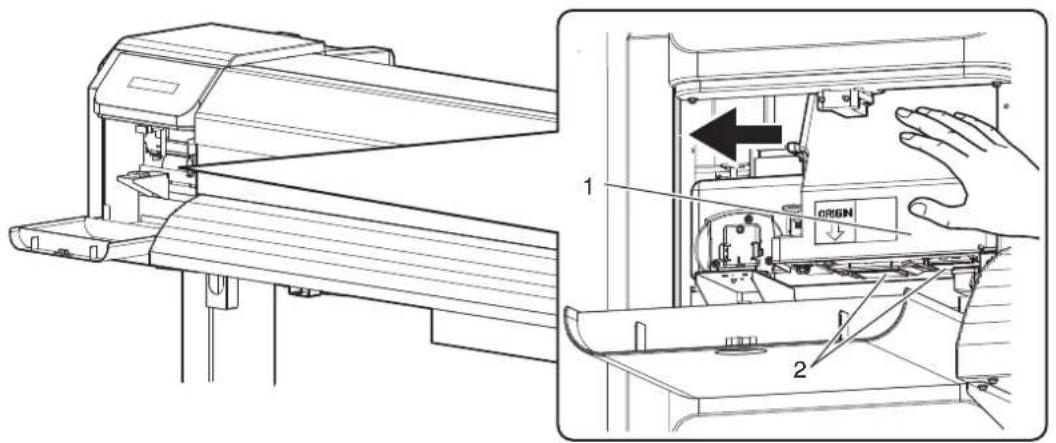
text_image
Technical diagram showing a printer's internal structure with labeled parts and directional arrows indicating assembly or operation.| No. | Name |
| 1 | Print head section |
| 2 | Circumference of Print head |

Do not push Print head strongly. It may cause damage and poor print quality.
- Use a penlight, etc to check if any foreign substance such as dust or ink clump is attached to the following places.
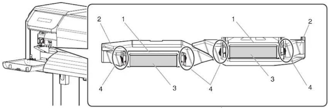
text_image
Technical diagram of a printer with labeled parts, showing front and side views of the device.| No. | Name |
| 1 | Circumference of Print head |
| 2 | Head guide |
| 3 | Nozzles |
| 4 | Dust, ink clump, etc |
CAUTION
- When cleaning around Print head,
- never touch Print head nozzles.
Doing so may damage Print head.
- Do not touch the tip of Cleaning stick.
Print head may be damaged because of oil from your hands.
- Never put water, etc on the tip of Cleaning stick.
Doing so may damage Print head.
- Do not reuse Cleaning stick.
The attached dust, etc may damage Print head.
- When some foreign substance such as dust or ink clump is attached, use Cleaning stick to remove it.
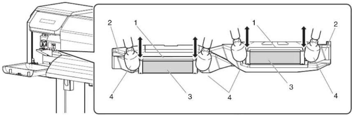
text_image
Technical diagram of a printer with labeled parts and directional arrows indicating assembly or process flow.| No. | Name |
| 1 | Circumference of Print head |
| 2 | Head guide |
| 3 | Nozzles |
| 4 | Cleaning stick |
- Close Maintenance cover on the left.
- Close Cover firmly until it is locked.
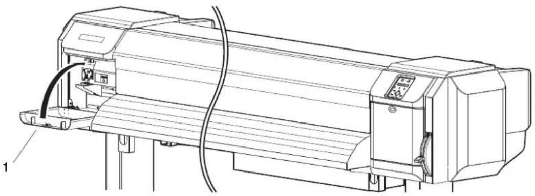
natural_image
Technical line drawing of a mechanical device with no visible text or symbols| No. Name |
| 1 Maintenance cover |
- Press the [Enter] key on Operation panel.

flowchart
graph TD
    A["Power"] --> B["* Receiving Data"]
    C["Error"] --> D["* Ink Low"]
    E["Head Height"] --> F["High"]
    E --> G["Low"]
    H["Menu"] --> I["Nazels Check"]
    H --> J["Pause"]
    H --> K["Control"]
    L["Output Mode"] --> M["Take Up @ 10"]
    L --> N["Auto Cut -"]
    O["Cleaning Mode"] --> P["Long"]
    O --> Q["Normal"]
    O --> R["Short"]
    S["Forward Mode"] --> T["Clearing"]
    U["Enter"] --> V["Forward"]
- Print head returns to its original position.
-
"CR Mainte.: Start" is displayed on Operation panel.
-
Press the [Menu] key on Operation panel.
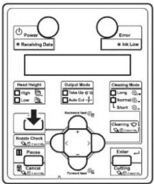
flowchart
graph TD
    A["Power<br>* Receiving Date"] --> B["Head Height<br>High Low"]
    C["Error<br>* Ink Low"] --> D["Output Mode<br>Take Up @ 10<br>Auto Cut -"]
    E["Nozzle Check<br>Pause Cancel"] --> F["Backward feed G1"]
    F --> G["Forward feed G2"]
    H["Cleaning Mode<br>Long Normal Short"] --> I["Enter Cutting"]
• The printer enters Normal.
- Cleaning the circumference of Print head is complete.
6.3 Disposal of waste fluids
The timing and method for the disposal of waste fluid are described below.
(1) Disposal timing
Dispose of waste fluids in the following cases:
a. When Waste fluid tank is more than half full.
b. When "Full WasteInkTank" is displayed on Operation panel.
(2) Disposal method
Follow the procedure below to dispose of waste fluid.

WARNING
- You are obligated to properly dispose of waste fluid from the printer in compliance with Wastes Disposal and Public Cleansing Act and local ordinances. Delegate disposal to an industrial waste disposal contractor.
- Ready an empty container such as a supply waste fluid bottle, to contain the waste fluid.
-
Lay a protective material, such as waste media, on the floor under Waste fluid tank.
-
Open the waste fluid valve, and transfer the waste fluid to the container.
NOTE
- When transferring the waste fluid to the empty container, the waste fluid may spatter. Make sure to put the container close to the waste fluid valve.

text_image
Technical diagram showing a hand operating a cylindrical container under a lift, with an inset close-up of the component being turned into a pump.| No. | Name |
| 1 | Waste fluid valve |
| 2 | Empty container |
- After pouring the waste fluid to the empty container, close the waste fluid valve securely.
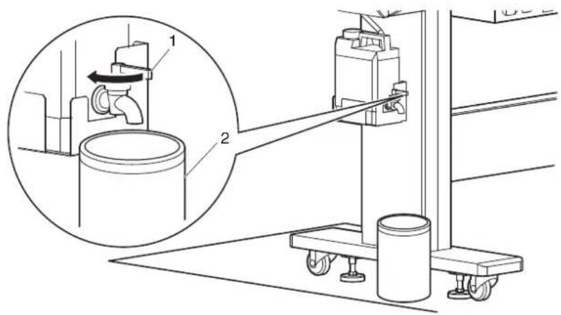
text_image
Technical diagram showing a mechanical assembly with labeled components and a magnified inset view of a cylindrical tank.| No. | Name |
| 1 Waste fluid valve | |
-
Wipe the opening of Waste fluid valve with a cloth, etc.
-
Dispose of the waste fluid as an industrial waste product.
- Disposal of waste fluids is completed.
6.4 Moving or transporting the printer
This section describes how to move or transport the printer.
6.4.1 Moving the printer
This section describes how to move the printer.

CAUTION
- When moving the printer, make sure to maintain a horizontal position.
- Do not slant the printer, prop it against a wall or turn it upside down.
The ink inside the printer may leak.
Moreover, normal operation after shifting (to these positions) cannot be guaranteed.
(1) Preparation before moving
When using the dedicated Stands, follow the procedure below to move the printer.
- Make sure that the printer is turned OFF.
3.2.2 Turning the power OFF - Dispose of waste fluid.
6.3 Disposal of waste fluids - Remove all the cables, such as Power cord set.
- Loosen the four adjusters of Stand as shown in the next illustration.
5. Move the printer.
NOTE
- The casters supplied with the dedicated Stand are manufactured for little movement in flat indoor areas, not for transporting equipment.
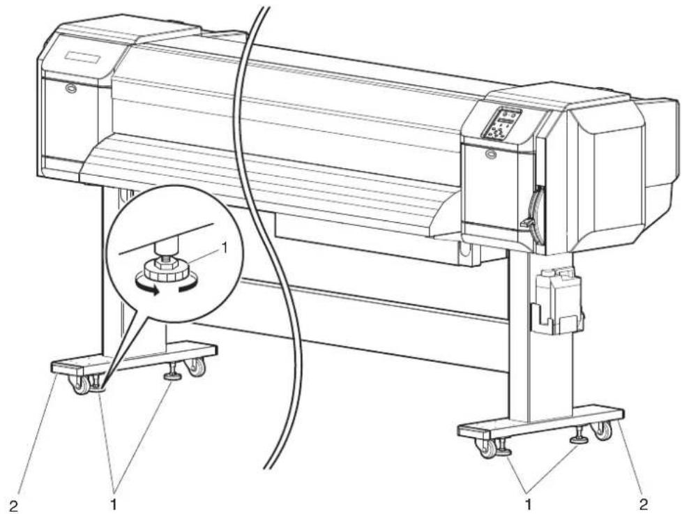
text_image
Technical diagram of a printer with labeled parts and a magnified inset showing the internal mechanism.| No. | Name |
| 1 | Adjusters |
| 2 | Stands |
(2) Reinstalling
After moving the printer, follow the procedure below to set it ready for use.
- Select a suitable place for installation.
Installation manual
-
Move and install the printer to the location.
-
Attach Cables, such as Power cord set.
3.1 Power cord set connection
3.7 Connecting the printer to PC
- Perform Nozzle check, and then confirm that there is no clogging in Print head.
3.5.1 Nozzle check
- Perform Alignment.
3.6 Print quality adjustment
6.4.2 Transporting the printer
When transporting the printer, make sure to pack it in the same condition as purchased, using protective and packing materials to protect the printer from vibration and shocks.
NOTE
- When transporting the printer, consult the MUTOH product dealer at your point of purchase.
7 Troubleshooting
This chapter describes possible troubles and countermeasures of this product.
If the error not included in any items of this section occurs, contact your local MUTOH dealer.
NOTE
- If you want to receive product warranty, prepare the warranty certificate.
If the warranty certificate is not presented, the repair will not be covered by the warranty even if within the warranty period.
If you have signed a maintenance service contract, prepare that or a similar document.
7.1 Malfunctions and failures
This section describes undisplayed malfunctions and failures of the printer, possible causes and countermeasures.
7.1.1 Problems in installation and introduction
(1) Cannot perform the initial ink charge
| No. | Possible cause Remedy Reference | ||
| 1 Is | Front cover open or Media loading lever raised? | Close Front cover, or lower Media loading lever. | 3.4 Loading media |
| 2 Is | Maintenance cover open? Close Maintenance cover. | 6.2.4 Cleaning Cleaning wiper6.2.5 Cleaning the circumference of Print head | |
| 3 Are all 8 Ink cartridges fully inserted? Fully insert all 8 Ink cartridges. | 6.1.1 Replacing Ink cartridges | ||
(2) Ink does not come out after the initial ink charge
| No. | Possible cause Remedy Reference | ||
| 1 Is | Ink cartridge cold and frozen? Leave Ink bag at | room temperature for at least three hours, and perform cleaning several times. | 6.2.3 Head cleaning |
| 2 Is | the power turned OFF during the initial ink charge? | Turn the power ON again and continue the initial ink charge. | 3.3 Filling ink |
| 3 Oc | casionally, normal printing cannot be performed after the initial ink charge. | Perform cleaning several times, and check it every time. | 6.2.3 Head cleaning |
7.1.2 Cannot print at all
(1) Does not work at all after power activation
| No. | Possible cause Remedy Reference | ||
| 1 Is | Power cord set connected to the plug? Connect | Power cord set. | 3.1 Power cord set connection |
| 2 Does the AC power supply provide the specified voltage? | Connect the cable to another outlet. | 3.1 Power cord set connection | |
| 3 Is | Front cover open or Media loading lever raised? | Close Front cover. Lower Media loading lever. | 3.4 Loading media |
| 4 Is | Maintenance cover open? Close Maintenance cover. | 6.2.4 Cleaning Cleaning wiper 6.2.5 Cleaning the circumference of Print head | |
(2) Does not work after loading the media
| No. | Possible cause Remedy Reference | ||
| 1 Is | Front cover open or Media loading lever raised? | Close Front cover. Lower Media loading lever. | 3.4 Loading media |
| 2 Is | Maintenance cover open? Close Maintenance cover. | 6.2.4 Cleaning Cleaning wiper 6.2.5 Cleaning the circumference of Print head | |
| 3 Is | the media loaded at an angle? Load the media straight. | 3.4 Loading media | |
| 4 Is | Ink cartridge inserted? Insert Ink cartridge. | 6.1.1 Replacing Ink cartridges | |
| 5 Are you using the recommended media? Use the recommended media. | 4.2.1 Media type | ||
| 6 Is | the printer being used in an environment other than the one specified, such as in direct sunlight? | Only use the printer in an environment that is specified for use. | Installation manual |
(3) When data is sent from the computer, an error occurs at the printer and nothing is printed
| No. | Possible cause Remedy Reference | ||
| 1 Is | the type of printer selected correctly at the computer? | Check that the printer type settings on the computer side and printer side are the same. | 3.7 Connecting the printer to PC |
| 2 Are | the interface requirements and command mode the same on the computer side and printer side? |
(4) Cannot use the computer online using LAN
| No. | Possible cause Remedy Reference | ||
| 1 Is | Network interface cable connected correctly? | Confirm the types of the cross and straight cables, and connect Network interface cable correctly. | 3.7.3 Connecting a network interface cable |
| 2 Are | the network settings configured correctly? | Configure the network settings correctly. | 5.1.23 IP Address menu to 5.1.25 Gateway menu |
| 3 Do | the printer's network settings match the computer's settings? | Match this product's network settings with the computer side environment. | 3.7.1 System requirements |
| 4 Does | Power lamp on Operation panel blink after sending printing data from the computer? | If Power lamp does not blink, contact the computer manufacturer. | — |
7.1.3 Media-related troubleshooting
(1) The media slips or is torn during initialization
NOTE
- If the media is jammed or torn, remove it according to "7.3 The media is jammed".
| No. | Possible cause Remedy Reference | ||
| 1 | Are you using the recommended media? Use the recommended media. | recommended media. | 4.2.1 Media type |
| 2 | Is the loading position of the media correct? Load the media correctly. | the media correctly. | 3.4.2 Setting Roll Media |
| 3 | Is the roll media loaded correctly? Load the roll media correctly. | media correctly. | 3.4.1 Loading roll media |
| 4 | Are there any foreign materials such as torn paper attached to Pressurizing roller? | Clean Pressurizing roller. | 6.2.2 Cleaning the inside of the printer |
| 5 | Is the printer being used in an environment other than the one specified, such as in direct sunlight? | Only use the printer in an environment that is specified for use. | Installation manual |
| 6 | Are you using creased, damaged, torn or curled media? | Replace the media. | 4.2.2 Cautions on handling media |
| 7 | Does the media bend? Use the recommended media. When using media other than the recommended one, set the Vacuum Fan menu. | When using media other than the recommended one, set the Vacuum Fan menu. | 4.2.1 Media type 5.1.1.1.7 Vacuum Fan menu |
(2) The media is crumpled during initialization
NOTE
- If the media is jammed or torn, remove it according to "7.3 The media is jammed".
| No. | Possible cause Remedy Reference | ||
| 1 | Are you using the recommended media? Use the recommended media. | recommended media. | 4.2.1 Media type |
| 2 | Is the loading position of the media correct? Load the media correctly. | the media correctly. | 3.4.2 Setting Roll Media |
| 3 | Is the media loaded at an angle? Set the media straight. | clean Pressurizing roller. | 3.4.2 Setting Roll Media |
| 4 | Are there any foreign materials such as torn paper attached to Pressurizing roller? | Clean Pressurizing roller. | 6.2.2 Cleaning the inside of the printer |
| 5 | Is the printer used in an environment other than the one specified, such as near an air conditioner? | Only use the printer in an environment that is specified for use. | Installation manual |
| 6 | Are you using creased, damaged, torn or curled media? | Replace the media. | 4.2.2 Cautions on handling media |
(3) The wrong media size is set during initialization
| No. | Possible cause Remedy Reference | ||
| 1 | Are you using the recommended media? Use the recommended media. | 4.2.1 Media type | |
| 2 | Is the media loaded at an angle? Set the media straight. | 3.4.2 Setting Roll Media | |
| 3 | When the media is set, does it curl upward? Straighten the media or set a new media. | 3.4.2 Setting Roll Media | |
| 4 | Is the printer used in an environment other than the one specified, such as near an air conditioner? | 3.4.1 Loading roll media | |
| 5 | Are you using media that has been printed on already? | 4.2.1 Media type | |
(4) Media jams frequently occur
NOTE
- If media other than the recommended one is used, correct media feeding cannot be assured.
| No. Possible cause Remedy Reference | |||
| 1 Are you using the recommended media? Use the recommended media. | 4.2.1 Media type | ||
| 2 Is the media used in an environment other than the one specified? | Use the media in the specified environment. | 4.2.2 Cautions on handling media | |
| 3 Are you using the old media? Replace it with the new media. | 6.1.2 Replacing Roll Media | ||
| 4 Are you using the creased or wrinkled media? | |||
| 5 Does the media bend? Use the recommended media. When using media other than the recommended one, set the Vacuum Fan menu. | 4.2.1 Media type5.1.1.1.7Vacuum Fan menu | ||
(5) The media veers during printing
| No. | Possible cause Remedy Reference | ||
| 1 | Are you using the recommended media? Use the recommended media. | 4.2.1 Media type | |
| 2 | Is the loading position of the media correct? Load the media correctly. | 3.4.2 Setting Roll Media | |
| 3 | Is the roll media loaded correctly? Load the roll media correctly. | 3.4.1 Loading roll media | |
7.1.4 Printing-related troubleshooting
(1) Printing is partially stained or incomplete
NOTE
- Proper print quality may not be obtained with the media other than the recommended one.
| No. | Possible cause Remedy Reference | ||
| 1 | Does the media include moisture? Replace it with | the new media. | 6.1.2 Replacing Roll Media |
| 2 | Are you using the creased or wrinkled media? | ||
| 3 | Does the media bend? Use the recommended media. When using media other than the recommended one, set the Vacuum Fan menu. | 4.2.1 Media type5.1.1.1.7Vacuum Fan menu | |
(2) The printing position is incorrect (some parts of the media cannot be printed on)
| No. | Possible cause Remedy Reference | ||
| 1 Is | the loading position of the media correct? Load | the media correctly. | 3.4.2 Setting Roll Media |
| 2 | Did you set up the origin and print position? | Cancel or reset the settings of the origin and print position. | 5.1.8 Origin menu |
(3) Printing is blurred
| No. | Possible cause Remedy Reference | ||
| 1 | Are you using the recommended media? Use the recommended media. | Recommended media. | 4.2.1 Media type |
| 2 | Are you using the thick or thin media? Use the recommended media. | Recommended media. | 4.2.1 Media type |
| 3 | Is the media printed on the printing surface? | Confirm the printing surface of the media and set it correctly. | 3.4 Loading media |
| 4 | Did you perform Micro adjust print? Perform Adjust print. | Adjust print. | 3.6 Print quality adjustment |
| 5 | Did you perform Media feed compensation? | Perform Media feed compensation. | 4.2.6 Media feed compensation |
| 6 | Is the temperature setting of each heater appropriate?(VJ-1638 only) | Set the temperature appropriately. | 5.1.1.1.4 Pre-heater menu (VJ-1638 only) to 5.1.1.1.6 Dryer menu (VJ-1638 only) |
| 7 | Is the head height set to "High" or "Mid"? | Return the head height to "Low". | 4.2.5 Head height adjustment |
(4) White or black lines appear on printed media
| No. | Possible cause Remedy Reference | ||
| 1 | Are you using the recommended media? Use the recommended media. | recommended media. | 4.2.1 Media type |
| 2 | Is the roll media loaded correctly? Load the roll media correctly. | media correctly. | 3.4.1 Loading roll media |
| 3 | Are Nozzles in good condition? Perform Head cleaning. | cleaning. | 6.2.3 Head cleaning |
| 4 | Did you perform Micro adjust print? Perform Adjust print. | Adjust print. | 3.6 Print quality adjustment |
| 5 | Did you perform Media feed compensation? Perform Media feed compensation. | Perform Media feed compensation. | 4.2.6 Media feed compensation |
| 6 | Is the temperature setting of each heater appropriate?(VJ-1638 only) | Set the temperature appropriately. | 5.1.1.1.4 Pre-heater menu (VJ-1638 only) to 5.1.1.1.6 Dryer menu (VJ-1638 only) |
| 7 | Is the head height set to "High" or "Mid"? | Return the head height to "Low". | 4.2.5 Head height adjustment |
(5) Printing lines are not straight
| No. | Possible cause Remedy Reference | ||
| 1 Is | Ink cartridge within the validity period? Use a new Ink cartridge. | 6.1.1 Replacing Ink cartridges | |
| 2 Are you using the recommended media? Use the recommended media. | 4.2.1 Media type | ||
| 3 Did you perform Micro adjust print? Perform Adjust print. | 3.6 Print quality adjustment | ||
| 4 Did you perform Media feed compensation? Perform Media feed compensation. | 4.2.6 Media feed compensation | ||
(6) Printing lines are duplicated or patchy
| No. | Possible cause Remedy Reference | ||
| 1 Are Nozzles in good condition? Perform Head cleaning. | 6.2.3 Head cleaning | ||
| 2 | Is the head height set to "High" or "Mid"? | Return the head height to "Low". | 4.2.5 Head height adjustment |
7.2 Error messages
This section describes messages displayed during normal printer operation or when errors occur, and solutions to the messages.
7.2.1 Status messages
This section describes messages displayed during printer normal operation.
When the printer is operating correctly, each operation status is displayed on Operation panel as below.
| No. | Display Description Reference | ||
| 1 | Ready to Print Standby (Media is loaded). — | ||
| 2 | Media End Standby (Media is not loaded). | 3.4 Loading media | |
| 3 | Receiving Receiving data. — | ||
| 4 | Analyzing data Analyzing data. — | ||
| 5 | Printing Under printing. | — | |
| 6 | PrintRestart --> ENTER Pausing printing.Press the [Enter] key. | 4.4.6 Pausing printing | |
| 7 | Warming Up | Warming up Heater.(VJ-1638 only) | — |
| 8 | Warming UpSkip -> Enter | Received the printing data while Heater is warming up.To start printing before Heater is warmed up, press the [Enter] key.(VJ-1638 only) | 4.4.7 Starting printing during warming up (VJ-1638 only) |
| 9 | Cleaning **% Cleaning the head.Please wait a while. | 6.2.3 Head cleaning | |
| 10 | Ink Refill **% | Filling the ink.Please wait a while. | 3.3 Filling ink |
| 11 | SubTank Refill | Filling the subtank.Please wait a while. | 3.3 Filling ink |
| 12 | Moving Origin Pos. | Print head is moving to the original printing position in the Origin menu.Please wait a while. | 5.1.8 Origin menu |
| 13 | Confirm Position -> Enter | Print head is moving to the original printing position in the Origin menu.Press the [Enter] key. | 5.1.8 Origin menu |
| 14 | During Washing | Cleaning Head.Please wait a while. | 5.1.19 Longstore menu |
| 15 | Remove Cartridges | Perform head cleaning.Remove Cartridge. | 5.1.19 Longstore menu |
| 16 | ** Initializing ** | Initializing the setting in the Initialization menu.Please wait a while. | 5.1.21 Initialization menu |
| 17 | Power Off Turning the printer off. | Please wait a while.Do not unplug Power cord set till Operation panel is turned off. | 3.2.2 Turning the power OFF |
| 18 | Change Head Gap Low Displayed in the following cases.During power shutdownBefore head cleaningSet the head height to Low. | 4.2.5.3 When setting the head height to Low | |
| 19 | Change Head Gap High Set the head height to HighStarts printing. | 4.2.5.2 When setting the head height to High | |
| 20 | Insert CleaningCart. Washing Print head. | Install Cleaning cartridge. | 3.3 Filling ink |
| 21 | Insert InkCartridges Filling the ink. | Insert Ink cartridge. | 3.3 Filling ink |
| 22 | User: Type ** OK? Initializing the media. | Please wait a while.(** represents the set User type.) | 3.4.3 Setting the User Type Setting |
| 23 | Media Initial | ||
7.2.2 Message type error display and remedies
This section describes message type errors and remedies.
Message type errors are displayed when certain failures occur during printer operation.
If a message type error occurs, the printer may display the following error messages on Operation panel and stop operation.
If the printer stops operating, solve the error so that the printer restarts.
NOTE
When an error occurs in the color measuring mode (numbers 26 to 38 below), clear the error and then press the [Cancel] key more than two seconds to solve the message type error.
| No. | Display Description Remedy Reference | |||
| 1 | Cover Open Front cover is open. | Close Front cover. | 3.4 Loading media | |
| 2 | Mainte.CoverL Open Left Maintenance cover is open. | Close Maintenance cover. | 2.2 Names of parts and functions | |
| 3 | Mainte.CoverR Open Right Maintenance cover is open. | Close Maintenance cover. | 2.2 Names of parts and functions | |
| 4 | Lower the lever | Media loading lever is raised. | Lower Media loading lever. | 2.2 Names of parts and functions |
| 5 | Lever Up The media is not loaded. Load the media. | 3.4 Loading media | ||
| 6 | Undefined Media Media detection has failed.(Stops operation) | Reload the media. | 3.4 Loading media | |
| 7 | Media Slant Media is fed obliquely.(Stops operation) | Reload the media. | 3.4 Loading media | |
| 8 | Media Cut Error The media was not cut.(Stops operation) | Reload the media. | 3.4 Loading media | |
| 9 | End Of Roll Roll media has run out.(Stops operation) | Load a new roll media. | 6.1.2 Replacing Roll Media | |
| 10 | Detach instrument | Spectrophotometer is installed when the colors are not being measured.(VJ-1638 only) | Remove Spectrophotometer (SPECTROVUE VM-10). | 4.5 Using Spectrophotometer (VJ-1638 only) |
| 11 | [******] Ink Low | The remaining amount of ink is low.(Continues operation) | Replace with a new S/C card and Ink cartridge. | 6.1.1 Replacing Ink cartridges |
| 12 | [******] Ink End | Ink has run out.(Stops operation) | Replace with a new S/C card and Ink cartridge. | 6.1.1 Replacing Ink cartridges |
| 13 | [******] Check Ink | Ink cartridges/Ink packs cannot be recognized correctly. | Insert Ink cartridge/Ink pack adapter again.Contact your local MUTOH dealer. | 6.1.1 Replacing Ink cartridges |
| No. | Display Description | Remedy | Reference | |
| 14 | [******] S/C ReadErr IC chip | cannot be read. Insert Ink cartridge again. If IC chip still cannot be read, insert a new Ink cartridge. | 6.1.1 Replacing Ink cartridges | |
| 15 | [******] S/C Col.Err Ink cartridge is inserted into a wrong Ink cartridge slot. | Insert it into the correct Ink cartridge slot. | 6.1.1 Replacing Ink cartridges | |
| 16 | [S] S/C Ink Err This type of ink can not be used for this printer. | Contact your local MUTOH dealer. | 6.1.1 Replacing Ink cartridges | |
| 17 | [S] S/C CodeErr An improper Ink cartridge is inserted. | Contact your local MUTOH dealer. | - | |
| 18 | [S] Broken Chip IC chip is broken. Replace with the new Ink cartridge. | Cartridge. | 6.1.1 Replacing Ink cartridges | |
| 19 | Full WasteInkTank Waste fluid tank is full.(Stops operation) | Dispose of waste fluid. | 6.3 Disposal of waste fluids | |
| 20 | Life Times [Head*] The operational life of Print head has almost expired.(Continues operation) | Contact your local MUTOH dealer. | - | |
| 21 | Life Times [Pump] The operational life of the pump motor is almost expired.(Continues operation) | Contact your local MUTOH dealer. | - | |
| 22 | Life Times [CR Motor] The life CR motor is almost expired.(Continues operation) | Contact your local MUTOH dealer. | - | |
| 23 | Life Times [PF Motor] The operational life of PF motor is almost expired.(Continues operation) | Contact your local MUTOH dealer. | - | |
| 24 | [******] Change Plug Time to replace Connector rubber of High-capacity ink pack adapter.(VJ-1638 only) | Replace Connector rubber. | High-capacity ink pack adapter Operation Manual "3.2 Replacing Connector Rubber" | |
| 25 | No connector cap. Connector cap is off the connector.(VJ-1638 only) | Install Connector cap to the connector of Spectrophotometer on Print head. | 4.5 Using Spectrophotometer (VJ-1638 only) | |
| 26 | Measurement Error (Take Up Roll) Media ejection mode is set to "Take-up".(VJ-1638 only) | Change the setting to "Off". | 5.1.6 Output Mode menu | |
| 27 | Measurement Error (Media detection) The Media detection menu is set to "Off".(VJ-1638 only) | Change the setting to either "Width" or "Top&Width". | 5.1.4 Media Set menu | |
| 28 | Measurement Error (Media width) The width of the media installed does not match the color target to be measured.(VJ-1638 only) | Remove the media currently set, and set a correct color target. | 3.4 Loading media | |
| No. | Display Description Remedy | Reference | ||
| 29 | Measurement Error (Command) | The parameters of the command sent from RIP software are abnormal. (VJ-1638 only) | Check the settings of color calibration or color profiling of the RIP software. | — |
| 30 | Measurement Error (Media End) | The media has run out while printing or measuring the color target. (VJ-1638 only) | Load new media and start printing and measuring the color target again. | 4.5 Using Spectrophotometer (VJ-1638 only) |
| 31 | Measurement Error (Cover Open) | Cover(s) opened while measuring the color target. (VJ-1638 only) | Close Front cover and Maintenance covers on both sides of the printer. | 3.4 Loading media6.2.4 Cleaning Cleaning wiper |
| 32 | Measurement Error (Lever Lifted) | Media loading lever is raised while printing or measuring the color target. (VJ-1638 only) | Printing or measuring is cancelled. Start printing and measuring the color target again. | 4.5 Using Spectrophotometer (VJ-1638 only) |
| 33 | Measurement Error (Communication) | A communication error occurred while printing or measuring the color target. (VJ-1638 only) | Check the communication requirements between the printer and your PC. | 3.7 Connecting the printer to PC |
| 34 | Measurement Error (Instrument) | A communication error with Spectrophotometer (SPECTROVUE VM-10) occurred while measuring the color target. (VJ-1638 only) | Check the connection between the printer and Spectrophotometer (SPECTROVUE VM-10). | 4.5 Using Spectrophotometer (VJ-1638 only) |
| 35 | Measurement Error (Cancelled) | Printing or measuring the color target has been cancelled from Operation panel or the RIP software. (VJ-1638 only) | Start printing and measuring the color target again. | 4.5 Using Spectrophotometer (VJ-1638 only) |
| 36 | Measurement Error (White Calibration) | White calibration has failed. (VJ-1638 only) | Open Maintenance cover on the left side of the printer and install White reference plate correctly.When White reference plate is contaminated, apply a damp and tightly squeezed soft cloth to clean it.Start printing and measuring the color target again.If you still have trouble, contact your local MUTOH dealer. | 4.5 Using Spectrophotometer (VJ-1638 only) |
| 37 | Measurement Error (Illegal Operation) | Colorimeter has been installed forcibly without following the measurement procedure. (VJ-1638 only) | Remove Colorimeter. | 4.5 Using Spectrophotometer (VJ-1638 only) |
| 38 | Measurement Error (Head height) | Head height is set to High (VJ-1638 only). | Set the head height to Low or Mid. | 4.2.5 Head height adjustment |
NOTE
- [**********] of the error display indicates the ink color that is subject to warning.
7.2.3 Error requiring restart
This section describes errors requiring restart and remedies.
An error requiring restart is displayed if a fatal operational failure such as the following occurs.
- When an obstacle that prevents printing occurs
- When a problem occurs with the electrical circuit (PCB, motor, sensor, etc.) of the printer
- When a failure in the printer control program occurs
If an error requiring restart occurs, the printer stops operating after performing the following operations.
-
The drive power automatically shuts down.
-
All Lamps on Operation panel blink, and the buzzer rings continuously.
-
The error message is displayed on Operation panel.
Pressing any key on Operation panel stops the beeping.
For an error requiring restart, operation will return to normal after removing the cause of the error and restarting the printer.
If the same error continues to be displayed, contact the your local MUTOH dealer.
Be sure to tell us the code no. of the error message when you contact us.
| No. | Display Description Remedy Reference | ||
| 1 E*** Error [ ] A problem that does not have a remedy has occurred. | 1. Remove obstacles such as paper scraps in the drive system.2. Confirm that the replaced items are correctly attached.3. Turn OFF the printer and turn it ON again after 10 seconds or longer. | 7.3 The media is jammed6.1 Replacing consumable components | |
NOTE
- "***" in the error message is the code no. that indicates what type of error occurred.
- The command code representing the error occurred may be indicated in [ ].
- For the settings on your PC side, refer to the Operating Manual attached with your PC.
7.3 The media is jammed
When the set media is jammed, follow the procedure below to remove it.
- Turn OFF the power of the printer.
3.2.2 Turning the power OFF
- Open Front cover.

natural_image
Technical line drawing of a mechanical device with no visible text or symbols| No. | Name |
| 1 | Front cover |
- Move Print head section from the top of the media to the right.
NOTE
- When the head height is set to Low, change it to High and then shift Head. After shifting Head, change the setting back to Low.
4.2.5.2 When setting the head height to High
4.2.5.3 When setting the head height to Low

text_image
Technical line drawing of a printer with labeled parts, showing hand operating the printer's internal structure.| No. | Name |
| 1 | Print head section |
| 2 | Roll media |
- Raise Media loading lever.

natural_image
Technical line drawing of a printer with internal components and wiring (no text or symbols)| No. | Name |
| 1 | Media loading lever |
- Pull the media to your side, and cut the torn part with cutting tools such as a razor blade.
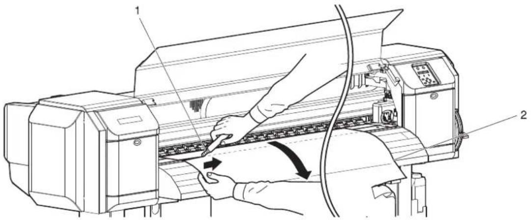
text_image
Technical diagram showing a printer printer with labeled parts and directional arrows indicating operation| No. | Name |
| 1 | Razor blade |
| 2 | Roll media |
- Turn Flanges of Roll media holder and take up the roll media.
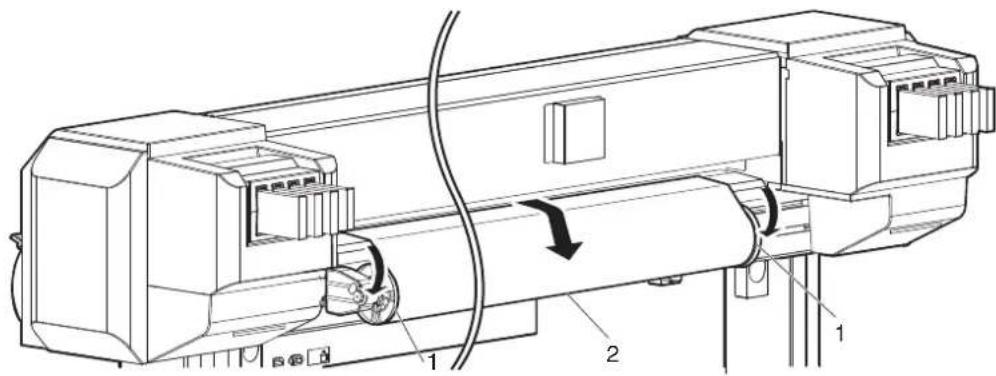
text_image
Technical diagram of a mechanical device with labeled components and directional arrows indicating motion or flow.| No. | Name |
| 1 | Flanges |
| 2 | Roll media |
- If paper dust or pieces of paper remain inside the printer, remove them.
8 Appendix
This chapter describes specifications and included components with this printer.
8.1 Product specifications
8.1.1 Printer specifications
| Items Specification | ||
| Model name VJ-1638 | VJ-1638W | |
| Printing method On-demand piezo drive system | ||
| Drive system Firmware servo/DC motor drive | ||
| Media feed system Multipoint pressurizing grid roller system | ||
| Media fixing system Pressurization roller down system by manual lever | ||
| Media feed/ejection Rear feed/Front ejection | ||
| Roll media outer diameter 150mm or less | ||
| Roll media weight 30kg or less | ||
| Maximum media width 1,625 mm | ||
| Minimum media width 900 mm | ||
| Maximum media thickness | 0.3 mm (when the head height is Low)/1.3 mm (when the head height is Mid)/2.8 mm (when the head height is High) | |
| Maximum printable media width | 1,615 mm | |
| Print margin | Top: 5 mm (15 mm after media initialization or after winding the media manually, 40 mm when media initialization front edge detection is ON or after cutting the media), Bottom: 5 mm (102 mm at the roll media end), Left: 5 mm to 25 mm, Right: 5 mm to 25 mm. | |
| Media cut system | Horizontal automatic cut system/manual cut system | |
| Head height adjustment | Three-level adjustment of Low, Mid, and High | |
| CPU | 64-bit RISC CPU | |
| Memory | 256 MB | |
| Command | MH-RTL (RTL-PASS) | |
| Interface | Network interface (Ethernet IEEE 802.3) | |
| Ink | Supply system | Supplied through tubes from independent color cartridges |
| Cartridges | < VJ-1638>Black, Cyan, Magenta, Yellow: 220ml ± 5ml each or 440ml ± 5ml (1000ml ± 5ml when the optional High-capacity ink pack adapter is used)< VJ1638W>Black, Cyan, Magenta, Yellow: 220ml ± 5ml each | |
| Items | Specification | |
| Environmental condition | Operating condition Temperature: 20°C to 32°CHumidity: 40 % to 60 %, No condensation | |
| Printing accuracy coverage | Temperature: 22°C to 30°CHumidity: 40 % to 60 %, No condensation | |
| Change rate Temperature: within 2°C per hourHumidity: within 5 % per hour | ||
| Archiving condition (Ink not filled) | Temperature: -20°C to 60°CHumidity: 20% to 80%, No condensationStorage life: six months | |
| Archiving condition (Ink filled) | Temperature: -10°C to 40°CHumidity: 20% to 80%, No condensationStorage life: four days (32°C or higher) | |
| Power Power voltage | AC 90 V to AC 132 V / | AC 198 V to AC 264 V |
| Frequency 50 Hz/60 Hz ± 1 Hz | ||
| Power consumption Printing | MAIN: 1100WHEATER: 1250W200 W | |
| Standby45 W38 W | ||
| Outer diameter Height | 1,261 mm (including the stands) | |
| Width 2,698 mm | ||
| Depth 885 mm | ||
| Weight | 221 kg | |
8.2 Interface specification
This section describes each type of interface specifications supported by this printer.
8.2.1 Network interface specification
| Items Specification | |
| Network type Ethernet IEEE802.3 | |
| Network I/F 10BASE-T/100BASE-TX Automatic transfer type(RJ-45 Connector twisted pair cable)MDI/MDI-X Automatic transfer | |
| Corresponding protocol TCP/IP |
8.3 Options/Supply list
For more information about the options and the supply items, contact your local MUTOH dealer.
INDEX
< Symbol >
[<] key 2-7
[>] key 2-7
[+] key 2-7
[-] key 2-7
< Numerics >
220ml Ink cartridges 3-10
440ml Ink cartridges (VJ-1638 only) 3-23
< A >
AC inlet 2-5
Adj. PatternALL 3-88
Adjust print 3-63, 3-78
Adjust Print menu 5-9
Adjuster 2-4
Auto Cleaning menu 5-28
Auto Cut lamp 2-8
< B >
[Backward↑] key 2-7
Before using 3-1
< C >
[Cancel] key 2-7
Cautions on handling media 4-5
Changing and confirming settings
while printing 4-29
Changing printer status 2-10
Changing Torque of Roll Media Holder 3-54
Cleaning cartridges 3-12, 3-24
Cleaning fluid pack 3-33
[Cleaning] key 2-7
Cleaning menu 5-36
Cleaning the circumference of Print head ..... 6-40
Cleaning the cleaning wiper unit 6-34
Cleaning the inside of the printer 6-29
Cleaning the outer case 6-29
Connecting a network interface cable 3-99
Connecting the printer to PC 3-98
Connector 2-4
CR Maintenance menu 5-32, 6-35, 6-41
Custom confirmation pattern 3-79
Custom micro adjustment pattern 3-88
Custom rough adjustment pattern 3-84
[Cutting] key 2-7
Cutting media 4-26, 4-27
< D >
Dedicated media 4-4
Display menu 5-44
Disposal of waste fluids 6-47
Dist.Adj menu 4-11
Dryer menu (VJ-1638 only) 5-15
Earth wire 3-4
Effect menu 5-8
[Enter] key 2-7
Error lamp 2-8
Error requiring restart 7-14
Exhaust Fan menu 5-31
< F >
Fatal operational failure 7-14
Features 2-2
Feeding media 4-24
Filling ink 3-9
For VJ-1638 3-11
For VJ-1638W 3-16
[Forward↓] key 2-7
Front cover 2-4
Front section 2-3
< G >
Gateway menu 5-34
Grid roller 6-32
< H >
Head cleaning 6-33
Head height adjustment 4-6
Head height adjustment lever 4-8
Head Travel menu 5-26
High lamp 2-8
How to fix the media firmly 4-17
<1>
IC chip card 3-33, 3-36
Idle Auto Cleaning 5-28
Important safety instructions 1-3
Individual Adj. pattern 3-93
Initialization menu 5-32
Ink cartridge slot 2-5, 3-29
Ink cartridges horizontally 3-30
Ink cartridges vertically 3-29
Ink Dry Time menu 5-22
Ink Status menu 5-29
Installing High Capacity Ink Pack Adapter
(option) for VJ-1638 only 3-32
Installing ink cartridges 3-39
Installing media holder plates 4-18
IP Address menu 5-33
< L >
Language menu 5-44
LCD display section 2-8
Length menu 5-45
Life Times menu 5-33
Loading roll media 3-39
Long lamp 2-8
Longstore menu 5-31
Low lamp 2-8
Maintenance 6-36, 6-42
Maintenance cover 2-4
Media cut groove 2-4, 4-28
Media feed compensation 4-11, 5-11
Media feed slot 2-5
Media guide 2-4, 2-5
Media holder plate 2-4
Media initialization ....3-54
Media loading lever 2-3
Media Set menu 5-20
Media type 4-4
Media Width menu 5-20
[Menu] key 2-7
Menu Option menu 5-37
Menu setup procedure 4-21
Menu setups on the operation panel .....4-21
Message type error display 7-11
Method of Cut menu 5-23
Mode print 3-60
Moving the printer 6-50
Multi Strike menu 5-26
< N >
Network interface cable 2-5
Network interface cable connector ....2-5
Normal 2-10
Normal lamp 2-8
[Nozzle Check] key 2-7
NozzleCheck 3-59
< 0 >
Operation keys 2-6
Operation Manual 1-2
Operation method 2-6
Operation panel 2-6
Origin menu 5-23
Output Mode menu 5-22
Palette print 3-62
Panel display 2-10
Panel setup menu 5-1
Panel setup menu overview 4-23
[Pause] key 2-7
Pausing printing 4-30
Platen 2-4
Platen Heater menu (VJ-1638 only) ....5-14
Power cable connection 3-2
Power cable plug 2-5
[Power] key 2-7
Power lamp 2-8
Precaution on storing media 4-5
Pre-heater menu (VJ-1638 only) 5-13
Preparing cables 3-98
Pre-printing Mode Auto Cleaning 5-29
Pressurizing rollers 2-4
Prev. Stick menu (VJ-1638 only) 5-25
Print flow chart 4-2
Print Mode menu 5-6
Print quality 4-3
Printer status 2-6
Printer status outline 2-10
Printing area 4-6
Printing Mode Auto Cleaning 5-29
Procedure for changing and confirming settings while printing ....4-29
Procedure for the media feed compensation value 4-11
Product overview 2-1
Product specifications 8-2, 8-4
Rear section 2-5
Replacing consumable components ....6-2
Replacing Cutter 6-18
Replacing ink cartridges 6-2
Replacing Roll Media 6-10
Replacing the flushing-box sponges ....6-12
Roll Length menu 5-30, 5-30
Roll media holder 2-5
< s >
Safety instructions 1-1
Setting Roll Media 3-44
Settings that can be changed or confirmed while printing ....4-30
Setup menu 5-1, 5-2
Setup menu display 2-10
Setup print 3-61
Side Margin menu 5-19
Side margin menu 4-18
Slant Check menu 5-27
Sleep mode menu 5-41
Sleep Mode Start menu 5-43
Spitting menu 5-16
Spitting Pass Count menu 5-17
Stand 2-4
Standard confirmation pattern 3-64
Standard micro adjustment pattern 3-73
Standard rough adjustment pattern ....3-69
Standby Heating menu (VJ-1638 only) .....5-25
Starting printing during warming up (VJ-1638 only) 4-31
Status 2-10
Status messages 7-9
Stopping printing operation 4-25
Strike Wait menu 5-27
submenu 4-21
SubnetMask menu 5-34
System requirements ....3-98
Take Up lamp 2-8
Temperature menu 5-44
Test print 3-56
Test print menu 3-56
TestPrint menu 5-35
Timer Setting menu 5-42
Transporting the printer 6-52
Troubleshooting 7-1
Turning the power OFF 3-7
Turning the power ON 3-6
Turning the power ON/OFF 3-6
< U >
User Type advanced setup menu 5-4
User Type menu 5-4
User Type Setting 3-52
User Type Setup menu 3-52
Using Spectrophotometer (VJ-1638 only) ..... 4-33
< V >
Vacuum Fan menu 5-15
Version menu 5-40
< W >
Warning labels 1-7
Warnings 1-2
Waste fluid tank 2-4
Waste fluid valve 2-5, 6-48
When setting the head height to High 4-8
When setting the head height to Low 4-10
When setting the head height to Mid 4-6
When using High-capacity ink pack adapter
for the first time on the printer
whose ink is filled. 3-38
Setup menu diagram
For details of the Setup menu configuration diagram, refer to the followings.
NOTE
- For details of each setup item, refer to followings:
- Setup menu diagram (Ready to Print):
1 "5 Panel setup menu"
- Setup menu diagram (Receiving / Converting / Printing):
4.4.4 Changing and confirming settings while printing
- The < > parts in each list are factory default settings (initial values).
Setup menu diagram (Ready to Print) (1/4)

flowchart
graph TD
A["Setup"] --> B["UserType"]
B --> C["To Setup menu diagram (Ready to Print)(2/4)"]
B --> D["Spitting"]
D --> E["<On> on Media Off"]
D --> F["Side Margin to 25 mm"]
D --> G["Media Initial off Top&Width <Width>"]
D --> H["Media Width (When Media Initial menu is "Off")"]
D --> I["MediaWidth (When Media Initial menu is not "Off")"]
B --> J["Output Mode"]
J --> K["<Off> take Up Auto Cut"]
J --> L["Method of Cut SingleCut - 2 steps <SingleCut - 3 steps> DoubleCut - 2 steps DoubleCut - 3 steps"]
B --> M["Origin"]
M --> N["Prev. Stick Off <On>"]
M --> O["Standby Heating 10 min. to <60 min.>"]
M --> P["Head Travel Data Machine <Media>"]
M --> Q["Multi Strike <1 cnt> to 9 cnt"]
M --> R["Strike Wait <0.0 sec> to 0.1 sec to 5.0 sec"]
M --> S["Slant Check Off <On>"]
M --> T["Auto Cleaning WaitingTime Off/10 min to <360 min> to 1440 min<br>PrintingTime <Off>/5 min to 180 min<br>Before Print <Off> On"]
M --> U["Ink Status K / k / C / c / M / m / Y / y"]
M --> V["Roll Length <Off> Roll 1 Roll 2 Roll 3"]
M --> W["Exhaust Fan Off <Low> High"]
W --> X["To Setup menu diagram (Ready to Print)(3/4)"]
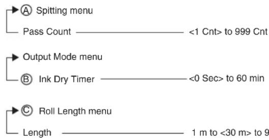
flowchart
graph TD
    A["Spitting menu"] --> B["Pass Count"]
    B --> C["<1 Cnt> to 999 Cnt"]
    D["Output Mode menu"] --> E["Ink Dry Timer"]
    E --> F["<0 Sec> to 60 min"]
    G["Roll Length menu"] --> H["Length"]
    H --> I["1 m to <30 m> to 9"]
Setup menu diagram (Ready to Print) (2/4)

flowchart
graph TD
    A["To Setup menu diagram (Ready to Print)(1/4)"] --> B["Print Mode"]
    B --> C["Quality 1"]
    B --> D["Quality 2"]
    B --> E["Quality 3"]
    B --> F["Quality 4"]
    B --> G["Graphics 1"]
    B --> H["<Graphics 2>"]
    B --> I["Banner 1"]
    B --> J["Banner 2"]
    B --> K["Banner 3"]
    B --> L["Banner 4"]
    B --> M["Effect"]
    M --> N["<None> *1"]
    M --> O["Wave"]
    M --> P["Fine&Fuzz"]
    M --> Q["<Fine&Fog> *1"]
    M --> R["A-S.Fine&Wave"]
    M --> S["B-S.Fine&Wave"]

    A --> T["Adjust Print"]
    T --> U["Standard"]
    U --> V["Confirm Pattern"]
    U --> W["Rough Pattern"]
    U --> X["Fine Pattern"]

    T --> Y["Custom"]
    Y --> Z["Confirm Pattern"]
    Z --> AA["Rough Pattern"]
    Z --> AB["Fine Pattern ALL"]
    Z --> AC["Fine Pattern A"]
    Z --> AD["Fine Pattern B"]
    Z --> AE["Fine Pattern C"]
    Z --> AF["Fine Pattern D"]
    Z --> AG["Fine Pattern E"]
    Z --> AH["Fine Pattern F"]

    A --> AI["PF Adjust"]
    AI --> AJ["VJ-1638 only"]

    A --> AK["PF Adjust menu"]
    AK --> AL["Initial Print 100 mm to <250 mm> to 500 mm"]
    AK --> AM["Initial Change <Initial Print menu setting value> ± 50.0 mm"]
    AK --> AN["Confirm Print 100 mm to <250 mm> to 500 mm"]
    AK --> AO["Micro Print -5.00% to <0.00%> to 5.00%"]
    AK --> AP["Micro Change -5.00% to <0.00%> to 5.00%"]
Setup menu diagram (Ready to Print) (3/4)
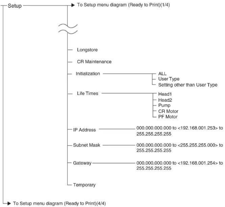
flowchart
graph TD
    A["Setup"] --> B["To Setup menu diagram (Ready to Print)(1/4)"]
    B --> C["Longstore"]
    B --> D["CR Maintenance"]
    B --> E["Initialization"]
    E --> F["ALL"]
    E --> G["User Type"]
    E --> H["Setting other than User Type"]
    E --> I["Life Times"]
    I --> J["Head1"]
    I --> K["Head2"]
    I --> L["Pump"]
    I --> M["CR Motor"]
    I --> N["PF Motor"]
    E --> O["IP Address"]
    O --> P["000.000.000.000 to <192.168.001.253> to 255.255.255.255"]
    E --> Q["Subnet Mask"]
    Q --> R["000.000.000.000 to <255.255.255.000> to 255.255.255.255"]
    E --> S["Gateway"]
    S --> T["000.000.000.000 to <192.168.001.254> to 255.255.255.255"]
    E --> U["Temporary"]
    U --> V["To Setup menu diagram (Ready to Print)(4/4)"]
Setup menu diagram (Ready to Print) (4/4)

flowchart
graph TD
    A["To Setup menu diagram (Ready to Print)(1/4)"] --> B["Test Print"]
    B --> C["Nozzle Check"]
    B --> D["Mode Print"]
    B --> E["SetUp List"]
    B --> F["Palette"]
    A --> G["Cleaning"]
    G --> H["Short"]
    G --> I["Normal"]
    G --> J["Long"]
    G --> K["LittleCharge"]
    G --> L["Initial Charge"]
    A --> M["Menu Option"]
    M --> N["User Type"] --> O["Off / <On>"]
    M --> P["Spitting"] --> Q["Off / <On>"]
    M --> R["Side Margin"] --> S["Off / <On>"]
    M --> T["Media Initial"] --> U["Off / <On>"]
    M --> V["Media Width"] --> W["Off / <On>"]
    M --> X["Output Mode"] --> Y["Off / <On>"]
    M --> Z["Method of Cut"] --> AA["Off / <On>"]
    M --> AB["Origin"] --> AC["Off / <On>"]
    M --> AD["Prev. Stick"] --> AE["Off / <On>"]
    M --> AF["Standby Heating"] --> AG["Off / <On>"]
    M --> AH["Head Travel"] --> AI["Off / <On>"]
    M --> AJ["Multi Strike"] --> AK["Off / <On>"]
    M --> AL["Strike Wait"] --> AM["Off / <On>"]
    M --> AN["Slant Check"] --> AO["Off / <On>"]
    M --> AP["Auto Cleaning"] --> AQ["Off / <On>"]
    M --> AR["Ink Status"] --> AS["Off / <On>"]
    M --> AT["Roll Length"] --> AU["Off / <On>"]
    M --> AV["Exhaust Fan"] --> AW["Off / <On>"]
    M --> AX["Longstore"] --> AY["Off / <On>"]
    M --> AZ["CR Maintenance"] --> BA["Off / <On>"]
    M --> BB["Initialization"] --> BC["Off / <On>"]
    M --> BD["Life Times"] --> BE["Off / <On>"]
    M --> BF["IP Address"] --> BG["Off / <On>"]
    M --> BH["Subnet Mask"] --> BI["Off / <On>"]
    M --> BJ["Gateway"] --> BK["Off / <On>"]
    M --> BL["ALL On"] --> BM["ALL Off"]
    A --> BN["Version"]
    BN --> BO["Ver.M(Main) / C(Controller)"]
    BO --> BP{For VJ-1638W, you cannot select "C (Controller)".}
    BP -->|Yes| B
    BP -->|No| C
    BP -->|No| AD
    BP -->|No| AE
    BP -->|No| AF
    BP -->|No| AG
    BP -->|No| AH
    BP -->|No| AI
    BP -->|No| AJ
    BP -->|No| AK
    BP -->|No| AL
    BP -->|No| AM
    BP -->|No| AN
    BP -->|No| AO
    BP -->|No| AP
    BP -->|No| AQ
    BP -->|No| AR
    BP -->|No| AS
    BP -->|No| AT
    BP -->|No| AU
    BP -->|No| AV
    BP -->|No| AW
    BP -->|No| AX
    BP -->|No| AY
    BP -->|No| AZ
    BP -->|No| BA
    BP -->|No| BB
    BP -->|No| BC
    BP -->|No| BD
    BP -->|No| BE
    BP -->|No| BF
    BP -->|No| BG
    BP -->|No| BH
    BP -->|No| BI
    BP -->|No| BJ
    BP -->|No| BK
    BP -->|No| BL
    BP -->|No| BM
    BP -->|No| BN
    BP -->|No| BO
    BP -->|No| BR
    BP -->|No| CA
    BP -->|No| CB
    BP -->|No| CC
    BP -->|No| CD
    BP -->|No| CE
    BP -->|No| CF
    BP -->|No| CG
    BP -->|No| CH
Setup menu diagram (Receiving / Converting / Printing)
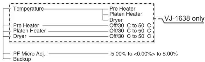
flowchart
graph TD
    A["VJ-1638 only"] --> B["Temperature"]
    A --> C["Pre Heater"]
    A --> D["Platen Heater"]
    A --> E["Dryer"]
    A --> F["Pre Heater"]
    A --> G["Platen Heater"]
    A --> H["Dryer"]
    A --> I["PF Micro Adj. Backup"]
    B --> J["Off/30 C to 50 C"]
    C --> K["Off/30 C to 50 C"]
    D --> L["Off/30 C to 50 C"]
    E --> M["Off/30 C to 50 C"]
    F --> N["-5.00% to <0.00%> to 5.00%"]
1 Safety instructions
This chapter explains about the printer installation, warning terms which the operator needs to know, caution items and warning labels stuck on the printer main unit.
2 Product overview
This chapter explains about the features of the printer along with the names and functions of each part.
3 Basic usage
This chapter explains how to handle the printer.
4 Daily maintenance
This chapter explains the step of the daily maintenance.
5 Troubleshooting
This chapter describes possible troubles during the use of this product and countermeasures.
MUTOH
| MUTOH INDUSTRIES LTD. Tel.:81-(0)3-6758-7020 Fax:81-(0)3-6758-7025 E-mail:ibd@mutoh.co.jp http://www.mutoh.co.jp/en/ index.html | MUTOH AMERICA INC. Tel.:1-480-968-7772 Fax:1-480-968-7990 E-mail:sales@mutoh.com http://www.mutoh.com | MUTOH BELGIUM nv Tel.:32-(0)59-561400 Fax:32-(0)59-807117 E-mail:mutoh@mutoh.be http://www.mutoh.be | MUTOH DEUTSCHLAND GmbH. Tel.:49-(0)211-385474-0 Fax:49-(0)211-385474-74 E-mail:vertrieb@mutoh-gmbh.de http://www.mutoh.de |
| MUTOH North Europe S.A. Tel.:352-445-906 Fax:352-447-093 E-mail:info@segroup.lu http://www.segroup.lu/ | MUTOH HONGKONG LTD. Tel.:852-2377-3411 Fax:852-2377-3422 http://www.mutoh.co.jp/en/ index.html | MUTOH SINGAPORE PTE.LTD. Tel.:65-6325-3150 Fax:65-6220-4342 http://www.mutoh.co.jp/en/ index.html | MUTOH AUSTRALIA PTY. LTD. Tel.:61-2-9437-1366 Fax:61-2-9436-2871 E-mail:sales@mutoh-au.com http://mutoh-au.com/ |