Falcon Outdoor 62 - Printer Mutoh - Free user manual and instructions
Find the device manual for free Falcon Outdoor 62 Mutoh in PDF.

User questions about Falcon Outdoor 62 Mutoh
0 question about this device. Answer the ones you know or ask your own.
Ask a new question about this device
Download the instructions for your Printer in PDF format for free! Find your manual Falcon Outdoor 62 - Mutoh and take your electronic device back in hand. On this page are published all the documents necessary for the use of your device. Falcon Outdoor 62 by Mutoh.
USER MANUAL Falcon Outdoor 62 Mutoh
natural_image
Large paper-cutting printer with penguin graphics being printed on its cover (no visible text or symbols)USER GUIDE
Falcon Outdoor46/62
Eco-Solvent Inkjet Printer
Mutoh America Inc.
2507 W. Erie Dr. Suite 103
Tempe, AZ 85282
United States
This equipment complies with radio interference regulations for data processing devices. When used in a residential area, this equipment may cause radio interference, in which case the user may be required to take appropriate corrective measures.
#Concerning radio interference
This product generates weak radio signals and may interfere with radio and television reception if not installed and used correctly. If you suspect that it is causing interference with radio and television reception, try one or more of the following measures:
- Change the direction of your reception antennae and feeders
- Change the direction of this product
- Change the distance between your receiver and this product
- Use separate power supply circuits for your receiver and this product
#Trademarks mentioned in this manual
- MUTOH, Falcon Outdoor, MH-GL, MH-GL/2, MH-RTL and RTL-PASS are trademarks or product names of MUTOH Industries Ltd.
- HP, HP-GL, HP-GL/2, HP-RTL are trademarks or product names of Hewlett-Packard Inc.
- Centronics, Bitronics are trademarks or product names of Centronics Data Computer Corp.
- Windows 95, Windows 98, Windows NT 4.0 are trademarks or product names of Microsoft Corp.
- DOS-V, PC-DOS are trademarks or product names of IBM (International Business Machines Inc.)
- NetWare is a trademark or product name of Nobel Inc.
- EtherTalk is a trademark or product name of Apple Computer Inc.
- Other names of companies or products are trademarks or product names of the respective companies.
!IMPORTANT
- Details of this product and this manual are protected by copyright held by this company and except for legitimate use by individuals, may not be copied, reproduced or distributed in whole or in part.
- Details contained in this manual may be subject to future alteration without notice.
- Details contained in this manual are believed to be correct but please contact this company or your dealer if you suspect an error or a point is not clear.
- In no event will this company be responsible for the consequences of using this product or this manual.
August 2002
Published: Mutoh Europe NV, Archimedesstraat 13, 8400 Oostende, Belgium
Copyright © August 2002, Mutoh Europe NV. All rights reserved.
Introduction
Dear Customer,
Mutoh's new Falcon Outdoor high-resolution drop-on-demand piezo electric outdoor inkjet printer series consists of two models.
The printer use a newly developed eco-solvent ink. Inks are offered in six colours. This User Guide deals with printer installation and operation methods as well as usage precautions. In order to use the printer safely and effectively, please read the User Guide carefully before you use the printer and then use it correctly.
Keep the manual beside the printer. It is sure to be useful in case something that you are not sure about should occur while you are using the printer.
!IMPORTANT
- Because the Falcon Outdoor is an inkjet printer, it needs to be cleaned and inspected periodically. User registration and a service contract are recommended for detecting trouble promptly and maintaining printing quality in top condition. For details, contact your local Mutoh dealer.
For Safe Usage
Introducing the safety symbol that is used in this manual.
The following warning indicator is used in this manual to prevent injury to the user and damage to property.
CAUTION
- Applies to a case where ignoring this instruction or incorrect action may lead to serious injury and may cause physical damage to the printer. You must read this and work correctly.
Introducing the Note and Reference symbols that are used in this manual.
!IMPORTANT
- An explanation of a matter that is very important for proper use of the printer. You must read this and work appropriately.

NOTE
- An explanation of a matter that is useful for you to know or that may affect the printing result. You should read this and bear it in mind.

REFERENCE
- A reference to where further useful detailed information is available. Refer to this if necessary.
CAUTION
Falcon Outdoor is a precision device. When you use it, be careful of the following.
- Do not use the printer in extreme heat, cold or humidity.
- Covers secured by screws must not be opened other than parts noted in this manual.
- Don't have a radio or television nearby as the printer may cause interference.
- Don't connect the printer cable to the same power source as an appliance that generates electrical noise.
- This printer uses 100 to 120V , or 200 to 240V AC power. Don't use it with power other than 100 to 120V , or 200 to 240V AC.
- Be sure to use a power source with an earth connection.
- Avoid placing objects on top of the printer or subjecting it to severe vibration or impact.
- Don't tilt or shake the printer when you move it. This may cause the ink to spill or the mechanism to malfunction. If tilting is unavoidable, contact your local Mutoh dealer.
- Don't wipe the printer with thinners or benzene.
- Be sure to use the Falcon Outdoor special cartridges (the printer will be damaged if an ink other than a special cartridge is used.)
- If the printer makes a strange noise or acts abnormally, refer to "When trouble strikes" on page 202 and contact your local Mutoh dealer.
- There is no question about the safety of the ink but since it is mildly toxic it should be kept out of the reach of children.

CAUTION
- Ink cartridges should be kept in a cool dark place. However, the ink will freeze if it is stored for a long period below -10°C for black ink and below -10°C for colored ink so storage under these conditions should be avoided. If the ink becomes frozen, it should be thawed for at least three hours at room temperature (25°C) before use.
- Don't put the hold lever in the up position while the head is moving (during printing, media size detection, media cutting and cleaning, etc.). The head and media keeper blade will touch, causing damage or faulty printing.
- When the hold lever is to be put in the up position for loading media, etc., make sure that the head is in a position where it will not touch the media keeper blade.
- Don't move the head while the hold lever is up. The head may touch the media keeper blade.
Contents
Introduction 7
For Safe Usage 7
Using the Printer 9
Contents 11
Before Using the Printer 17
Usage Environment 18
Names of Parts 19
Control Panel Names 20
Preparing for Printing 27
What's in the Box 28
Assembling the Stand 29
Assembling the Printer 33
Connecting the Power Cable / Disconnect Device 37
Ink Cartridge Precautions 38
Loading the Ink Cartridges 40
Specify the Type of Media 46
Loading the Media 48
Loading Cut Media 49
Loading Roll Media 52
Loading media in combination with the Roll Take-Up System 58
Using Pre- and Post-Heater 65
Making a Test Print 66
Connecting the Interface Cable 67
To Receive Data from the Computer 68
Input Port 68
Online Set-up 68
Command Set-up (User Settings) 69
Printing the Setup Lists 70
Making a Manual Cut 71
Direct Access Keys 73
Specifying the Media to be Used 74
Specifying the Resolution 75
High Quality Printing, Normal Printing, High Speed Printing 77
Head Cleaning 78
Cutting the Media 79
Making a Test Print and a Setup List Print 80
Media Feed 81
Reverse Media Feed 82
Fine Adjustment of Print Quality 83
Menus 87
Menu Mode Operation 88
Menu Levels 90
When You Want to do This 93
To use roll media efficiently 94
To speed up printing time 94
To improve printing quality 95
To connect with Centronics 95
To connect with network (Ethernet) 95
To cut roll media 95
To place printed output is a specified position 96
To use colour effectively 97
To check the status of the printer 97
To use another type of ink 97
To check printer set-up 98
Explanation of Functions 99
Understanding the Functions 100
Command Settings 100
Function Settings 103
Centronics Settings 107
Network Settings 107
Utility Settings 108
How to set Parameters 111
Command Settings 113
Command
Plot Area 114
Position
Terminator
Resolution
Online Timer 118
Overwrite 120
Origin Reset 121
Function Settings 122
Ink Dry Time 122
Halftone
CMY → Black 125
Scale
Mirror
Direction 128
Cut Position 129
Media Cut 130
Copy
Ink Density 132
Distance Adjustment 133
Centronics Settings 136
Mode
Timing
Network Settings 138
IP Address 138
Utility Settings 140
Error Display 140
Initial : All 141
Initial : Command 143
Initial : Function 145
Initial : Centronics 147
Initial : Network 149
Dump
Wash
Clean
Fill
Ink Change 159
Accuracy Adjustment Plot 162
Installation of Options 165
Network Interface Board Installation 166
Memory Extension 168
Details of the Display 171
Printer Status Display 172
Messaged Errors and Countermeasures 174
Data Error Display and Countermeasures 177
Command Error Display and Countermeasures 178
Errors Requiring a Restart 180
Errors Requiring Restart that Involve the Mechanical System 180
Errors Requiring Restart that Involve the CPU System 182
Errors Requiring Restart that Involve the Heater System 184
Daily Maintenance 187
Cleaning the Printer 188
Replacing Ink Cartridges 191
Switching Inks 192
Replacing the Cutter 196
Replacing Waste Liquid Absorbent Sheet (Waste Ink Bottle) 198
Cleaning the Cleaning Wiper 200
When Trouble Strikes 202
Nothing happens after power is switched on 202
Nothing happens after media is loaded 202
Nothing happens after the computer sends data 203
When printer sends data, the printer shows an error and does not print 203
Parts of the print are dirty or missing 203
It prints but the position is not right
(There are places that cannot be printed) 204
Media jams occur frequently 204
Roll paper is not cut cleanly 204
Ink initial filling fails 205
Ink does not appear even after initial filling 205
Media comes off or is torn during media initialisation 205
Media wrinkles during media initialisation 206
Thin media is not detected 207
Wrong media size in media initialisation 207
Media is skewed during printing 207
Cannot install printer driver 208
Cannot go online with Centronics 208
Printed line is blurred 209
White and black bands appear in printing 209
Printed lines do not join 209
Periodical Maintenance 210
Appendix 211
Printer Specifications 212
Interface Specifications 213
Centronics Interface Specifications
(Bi-directional Parallel Interface : IEEE1284 Compatible) 213
Network Interface (option) Specifications 215
List of Optional and supply Items 216
Before Using the Printer
This section lists matters that must be attended to before the printer is used.
| Usage Environment | PAGE 18 |
| Names of Parts | PAGE 19 |
| Control Panel Names | PAGE 20 |
An appropriate location for installing the printer should be selected after referring to the following conditions for the installation site and installation space.

CAUTION
• Always use a separate, earthed power outlet.
- Avoid places subject to sudden change of temperature or humidity, dust, or the direct rays of the sun.
- The Falcon Outdoor printer should not be in the direct draft from an air conditioner.
- Don't block the ventilation holes of the Falcon Outdoor printer.
- The floor should be level and free from vibration.
- Avoid places near a device that produces heat, such as a stove or heater.
- Avoid using the printer under strong light globes or halogen lamps.
Environmental Conditions for the Installation Site
We recommend setting up the printer in a place that conforms to the conditions in the following table.
With regard to temperature and humidity in particular, even if the conditions fall within the ranges indicated, places subject to sudden changes should be avoided.
We recommend setting up in a place that can be air conditioned in order to maintain constant temperature and humidity.
| Area for Installation At least | 3 m2 with a doorway of 1.5 m |
| Floor Strength At least 2490 | Pa (300 kg/m)2) |
| Power Supply Voltage 100 V | to 120 V AC 10% or200 V to 240 V AC 10% |
| Frequency | 50/60 Hz 1% |
| Capacity | Use a power outlet rated for at least 10 A |
| Temperature 10°C to 35°C (16°C to 25°C for assuredprinting accuracy)Variation rate: Not more than 2°C per hour) | |
| Humidity 35% to 80% (50% to 60% for assuredprinting accuracy) with no condensationVariation rate: Not more than 5°C per hour) | |
Leave at least 1 m in front, at the rear and at the sides.
Names of Parts

text_image
Front Cover Y-rail Cover Operating Panel Right Cover Left Cover Heater Panel Pressure Lever Waste Bottle Front Paper GuideControl Box Take-up System

text_image
Cartridge Cover 6 Ink Slots Waste Bottle Scroller Adjusting Screw Rear Paper Guide Scroller Scroller Slip Ring 3 Faleem-025192 OPEN GUIDE (AP-75046)Control Panel Names
The control panel is for setting operating conditions, displaying printer conditions and making settings for various functions.

flowchart
graph TD
    A["CANCEL key"] --> B["ERROR LED (Red) CLEANING key"]
    B --> C["DATA LED (Green)"]
    C --> D["ERROR"]
    D --> E["CANCEL"]
    E --> F["Cut Media Cancel Current Job"]
    F --> G["Set-up List"]
    G --> H["VACUUM HIGH LOW"]
    H --> I["QUALITY / SPEED key"]
    I --> J["High Quality LED (Green)"]
    I --> K["Normal LED (Green)"]
    I --> L["High Speed LED (Green)"]
    L --> M["MEDIA WEIGHT key"]
    M --> N["Standard LED (Orange)"]
    M --> O["Thin LED (Green)"]
    P["CANCEL key"] --> Q["QUALITY / SPEED key"]
    Q --> R["High Quality LED (Green)"]
    Q --> S["Normal LED (Green)"]
    Q --> T["High Speed LED (Green)"]
    U["MEDIA key"] --> V["Roll Media LED (Green)"]
    U --> W["Sheet Media LED (Green)"]
    X["MEDIA key"] --> Y["Resolution key"]
    Y --> Z["Low LED (Green)"]
    Y --> AA["High LED (Green)"]
| Nr. | Key | Description |
| 1. | Data LED : | The DATA LED monitors DATA status :LED ONindicates data is being received.LED FLASHINGmeans data is being processed. |
| 2. | Error LED : | The ERROR LED isONafter an ERROR has occurred, to indicate a possible hazardous situation.The LED will go out if the error is corrected or after pressing the [CANCEL] key. |
| 3. | Cancel : | The [CANCEL] keyis a special key, controlling both the CANCEL FUNCTIONas well as theROLL MEDIA sheet-off function.Printer ConditionResult by pressing CANCELIdle Status Roll media is cut at the current positionReceiving Status Process stopsProcess Status Buffer is clearedPrinting Status Print is cancelled, buffer is cleared, printed part is cut-off.To request a sheet-off, press cancel for 2 seconds and confirm with [ENTER]. |
| 4. | Cleaning : | - Pressing for 2 seconds initiates thecleaning procedure.- When pressed togetherwith the [SHIFT] key,(9) it initiates theheadadjustment procedure.- Go to thePrevious Menu, when inmenu-mode operation.- For advanced Cleaning Control, enter the menu system and select submenu [Utility] – option [Clean]. |
| 5. | Quality / Speed :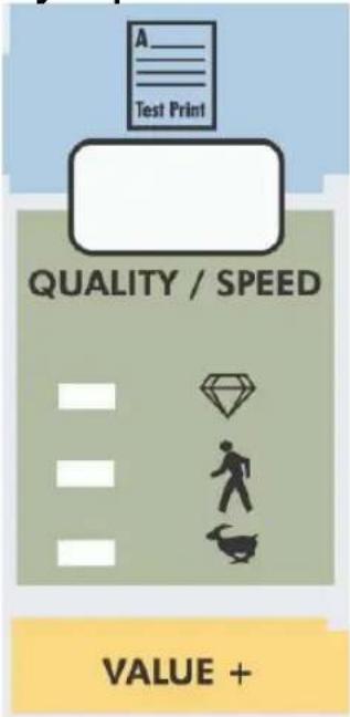 | - PressingQUALITY / SPEEDwill change the output quality and speed. Each time the key is pressed you will notice the LED indicator showing the current status :High quality,Normal and High Speed.- The set-up can only be changed in idle status.- When pressed togetherwith [SHIFT] key(9) outputs theTest Print.- Go to theNext menu option, or increase a parameter valuewhen inmenu-mode operation.- The LED indication is also influenced by data coming from the RIP/driver software. |
| 6. | Resolution : | - Pressing RESOLUTION will change the output resolution between 360 DPI, 720 DPI or 1440 DPI. The set-up can only be changed in idle status.- When pressed together with the [shift] key (9) it allows reverse manual roll feed.- Select the previous menu option and decrease a parameter value when in menu mode operation.- If both LEDs are ON simultaneously the plotter operates in one of the 3 available 1440 dpi modes (horizontal, vertical or diagonal).- The LED indication is also changed by data coming from the RIP software. |
| 7. | Media :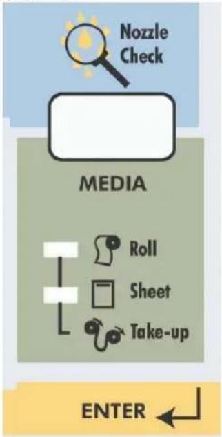 | - Allows selection among roll, cut-sheet or media take-up system support.- When pressed together with the [shift] key (9), generates a nozzle check print.- Accept a new setting when in menu mode or enter a lower menu level. |
| 8. | Menu Mode Operation : | The Menu Mode Operation is used to change printer settings and parameters. Menu Mode related buttons are enclosed in the yellow area. |
| 9. | Shift-button : | - Shift button to activate Head Adjustment, manual roll feed (forward or reverse), Nozzle check print, Test print or Set-Up List.- Back out of menu levels or switch back to ONLINE level from top level (Menu mode operation). |
| 10. | Menu : | - The Menu Mode Operation is used to change printer settings and parameters.- Press the [MENU] key to switch from ONLINE status to menu mode operation.- When pressed together with the [shift] key (9) it allows forward manual roll feed. |
| 11. | Liquid Cristal Display : | 16 characters LCD display which displays messages, shows settings / values and allows menu-wise control. |
12.
Vacuum :

text_image
Set-up List VACUUM HIGH LOW- The Vacuum key allows you to reduce the fan power when using very light media such as synthetic paper or uncoated paper lighter than 70 g/m².
- When pressed together with the [SHIFT] key, (9) it initiates a Set-up List and an adjustment parameter plot.

Note :
- When the data light is ON (receiving) or blinking (processing), all the keys are disabled, except the head cleaning key.
The keys will be operational in case of receiving data while you are in the setup menu. The settings changes, however, will then only be valid for the next printing job. - Panel set up from the printer is only possible when no printing data or processing data is sent to the printer.
• In menu mode operation, the shift key functions are not available.
flowchart
graph TD
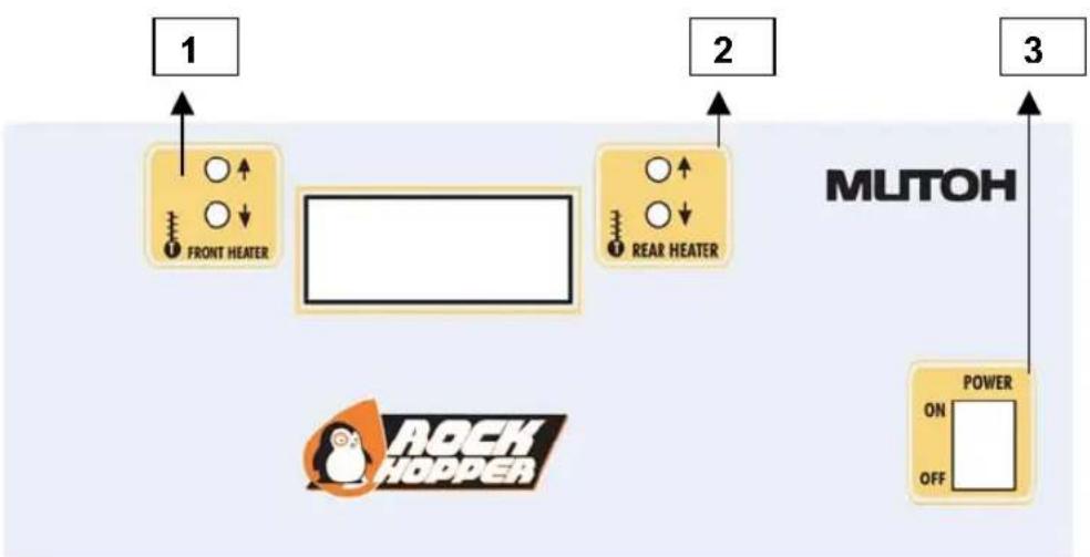
A["1 FRONT HEATER"] --> B["2 REAR HEATER"]
B --> C["3 POWER ON OFF"]
style A fill:#f9f,stroke:#333
style B fill:#f9f,stroke:#333
style C fill:#f9f,stroke:#333
1 = Controls Front Heater
2 = Controls Rear Heater
3 = Power Switch
Power Switch:
Control for power ON or OFF the Heater System.
Controls Front Heater:
Set temperature for the front heater. Real (RT) and set (ST) temperature are displayed on the LCD screen. The maximum temperature is 50 °C. By pushing the buttons you can select an appropriate temperature.
Controls Rear Heater:
Set temperature for the rear heater. Real (RT) and set (ST) temperature are displayed on the LCD screen. The maximum temperature is 50 °C. By pushing the buttons you can select an appropriate temperature.
Preparing for Printing
This section deals with preparations for using the printer.
| What's in the Box | PAGE 28 |
| Assembling the Stand | PAGE 29 |
| Assembling the Printer | PAGE 33 |
| Power Cable / Disconnect device | page 37 |
| Ink Cartridge Precautions | PAGE 38 |
| Loading the Ink Cartridges | PAGE 40 |
| Specify the Type of Media | PAGE 46 |
| Loading the Media | PAGE 48 |
| Using Pre- and Post heater | PAGE 65 |
| Making a Test Print | PAGE 66 |
| Connecting the Interface Cable | PAGE 67 |
| To Receive Data from the Computer | PAGE 68 |
| Printing the Setup List | PAGE 70 |
| Making a Manual Cut | PAGE 71 |
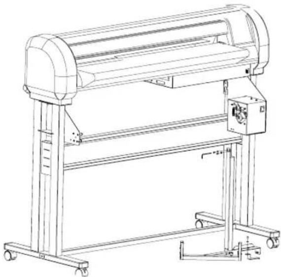
What's in the Box
What's in the box?
- Falcon Outdoor printer unit
- Printer stand
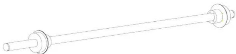
- 2 media scrollers (2" / 3") including plastic flanges
• 1 Sheet-off knife, pre-installed in head
• In-the-box RIP software - Scroller Slip Ring
natural_image
Technical line drawing of a mechanical housing or enclosure with internal compartments and structural supports (no text or symbols)Accessories kit consisting of:
- Power cable
- User's Guide
• Extra Box with Roll Take-Up System
natural_image
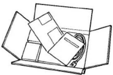
Simple line drawing of an open box containing folded paper sheets and a cable (no text or symbols)Assembling the Stand

Caution:
- Before lifting the printer body out of the box, make sure to remove all plastic wrapping materials first, in order to avoid that the machine slips from your hands.
Step 1:
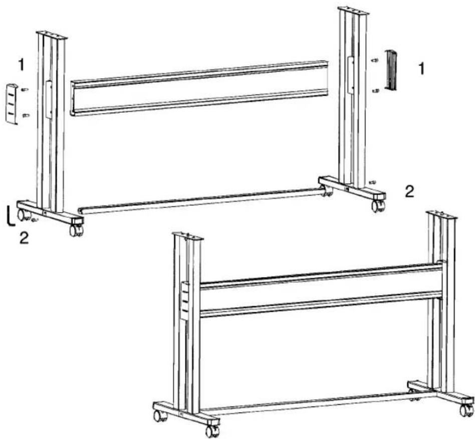
Unpack the stand and assemble it by screwing the left and right stand legs to the cross beam (upper bar)(1) and to the cross bar (lower bar)(2). To do this, use the 4 long hexagon bolts and the large hex wrench provided to secure the cross beam (1), and 2 long hexagon bolts to secure the cross bar (2). Make sure the caster wheels are on the front. After securing the bolts permanently, put on the two plastic side covers.
text_image
Technical diagram of two mechanical frame assemblies with labeled components and dimensionsStep 2 :
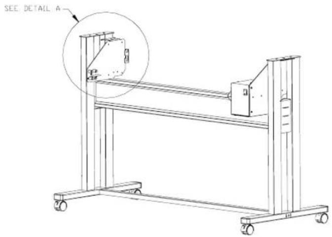
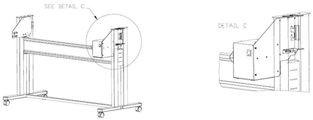
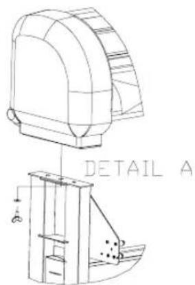
First make sure to mount the left end plate (plate without motor box) to the left leg of the stand.
Hook the left end plate between the leg assembly. Turn the left end plate diagonally, so that you can put it in-between the left leg and then turn it right to fix it into place by means of the hooks.
text_image
SEE DETAIL A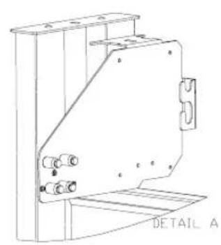
natural_image
Technical line drawing of a mechanical component with mounting flanges and a base plate (no text or symbols)Fasten the left end plate temporarily with 2 bolts + washers (use a 3 mm hex key) onto the bracket.
natural_image
Technical line drawing of a mechanical frame assembly with wheels and a circular inset showing a detail (no text or symbols)
natural_image
Technical line drawing of a mechanical lifting or bracket assembly (no text or symbols)Push the endplate as much as possible to the upper side of the leg assembly, so you can easily screw the printer body onto the stand.
text_image
SOE DETAIL E
text_image
DETAIL CStep 3 :
Hook the right end plate between the leg assembly. To do so, follow the same procedure as for the left end plate.
Hook the right end plate between the leg assembly. Turn the right end plate diagonally, so that you can put it in-between the right leg and then turn it right to fix it into place by means of the hooks.

natural_image
Technical line drawing of a mechanical frame with wheels and a circular inset highlighting a detail area (no text or symbols present)
natural_image
Technical line drawing of an electrical enclosure with mounting brackets and internal components (no text or symbols)Fasten the right end plate temporarily with 2 bolts + washers (use a 3 mm hex key) onto the bracket.
Push the endplate as much as possible to the upper side of the leg assembly, so you can easily screw the printer body onto the stand.
CAUTION
- For safety, at least four people are needed for assembling the printer.
- When taking the main unit out of the carton, remove the vinyl first and handle the printer directly. There is a risk of your hands slipping if the main unit is handled with the vinyl on.
- The main unit must be lifted by four people at the places marked (1) to (8) below. If it is lifted at other places (left and right side covers, ink cartridge cover, side plates, etc.) the printer may fall and cause injury or damage.

text_image
Side Section Rear Paper Guide 4 5 3, 6 2, 7 1 8 Front Paper Guide Top View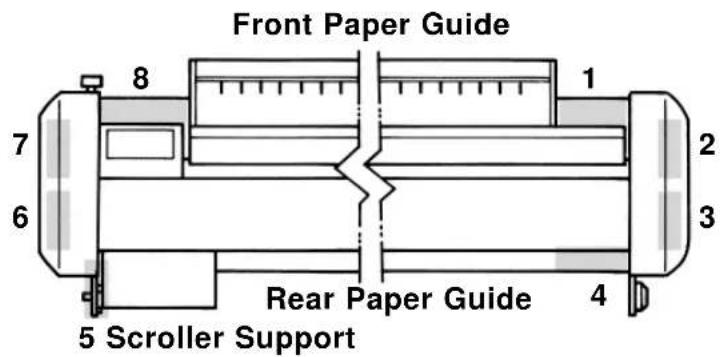
text_image
Front Paper Guide 8 7 6 1 2 3 Rear Paper Guide 4 5 Scroller SupportStep 1: Fix the printer body onto the leg assembly using the two wing screws. As mentioned in step 2 & 3 (Assembling the stand) the end plates should be pulled as much as possible towards the upper part of the stand. To do so, loosen a little bit the bolts temporarily fixing the endplates with a hex key of 3 ~mm and make sure that they are pulled as much as possible towards the stand. Now you can fix both wing screws firmly. Once the wing screws are fastened, you can secure the bolts on the endplates (see step 2 & 3) firmly with the hex key.
text_image
DETAIL AStep 2 :
The sensor assembly should be mounted on the right side of the stand. Take the sensor bracket and put it through the outer slothole of the sensor assy.
natural_image
Technical line drawing of a cylindrical industrial machine with wheels and control panel (no text or symbols)Now you can fix the sensor assy.
text_image
SEE DETAIL A SEE DETAIL BFix the sensor assembly smoothly to the motor box, using 2 bolt + washers (use upper holes) (detail A).
Hook the sensor bracket over the leg and secure it with a bolt + washer (detail B).

natural_image
Technical line drawing of an electrical control box with mounting bracket and internal components (no text or symbols)
natural_image
Line drawing of a mechanical cart with wheels and a labeled section 'DETAIL B' (no other text or symbols)Step 3:
Loosen the wing screw which is fixed to the printing table (4) and remove the metal fixing plate (5), which blocks the printer head during transportation. (See 4 & 5 on figure below). Keep the metal fixing plate and wing screw, since the printing head needs to be blocked during any transportation of your printer.

Caution:
- Take care not to drop the wing screw inside the printer body. Should it fall in, do not boot up your printer until the wing screw has been safely removed.
Remove the tape that locks the sheet-off mechanism during transportation (See 6 on figure below).

text_image
Technical diagram showing mechanical assembly with numbered components and directional arrows indicating motion or forceStep 4:
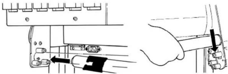
Remove the cable block(s) between rail and cover (7).

natural_image
Hand holding a tool interacting with a wooden plank (no text or symbols visible)Remove the lever block (8).
natural_image
Diagram of a hand adjusting a mechanical component with an arrow indicating a measurement (no text or symbols present)Step 5 :
Install the Waste Bottle (2 screws). Do not forget to connect the connector and the waste tubes.
Step 6:
After setting up the printer, wheel it to the desired location and lock the caster wheels.
natural_image
Line drawing of a hand holding a cylindrical object with a ring, no text or symbols presentConnecting the Power Cable
1) Make sure the printer's power switch is turned OFF.
2) Make sure the power of the Heating System and the Roll Take-Up System are turned OFF.
3) Plug the printer-end of the power cable into the connector at the back of the printer.
4) Connect the cable of the Roll-Take-Up System with the Printer body.
5) Plug the other end of the power cable into an electrical outlet of the correct voltage and with a proper grounding.
• Power supply:
- Voltage: 200 to 240 VAC or 100 to 120 VAC
- Frequency: 50/60 Hz ± 1 Hz
- Current: < 10 A (110 V)
$$ < 5 \mathrm{A} (2 2 0 \mathrm{V}) $$

natural_image
Warning symbol of a light bulb inside a triangle (no text or numbers)Note:
- When you turn off the power, please note that your printer needs a few seconds to perform its shut down sequence.
- To this end, wait for at least five seconds to switch the printer on again.
- The disconnect device is the plug on the power supply cord.
CAUTION
- Although there is no question about the safety of the ink, it should not be touched, licked or swallowed. If you accidentally touch the ink, wash it off immediately with soap and water. If it should get into your eye, wash with plenty of water and consult your doctor. If it is licked, wash it out immediately by gargling with water. If it has been swallowed, drink plenty of water immediately and you must see a doctor.
- For the reasons given above, ink cartridges should be kept out of reach of children as it would be dangerous for them to be licked or swallowed.
- The ink in ink cartridges burns easily so direct contact with heat or flame should be avoided.
- Ink cartridges may leak so they should not be shaken roughly or dismantled. If the ink leaks, wipe it up with a sponge and discard it in a sealed container.
- Ink cartridges should be discarded in accordance with local government regulations.
!IMPORTANT
- Before installing or changing to Eco-Solvent ink, perform a Head Wash. The tubes and heads must be clean. Use the special Eco-Solvent Transition Liquid.
- No need for special ventilation or environmental equipment.
- Once you have worked with Eco-Solvent inks, it is forbidden to change to another ink type.
- Prints are UV- and water-resistant for up to three years outdoors, when using Eco-Solvent ink. Lamination is required for heavy-duty applications.

NOTE
- Ink cartridges should be kept in a cool dark place. However, the ink will freeze if it is stored for a long period below -10°C for black ink and below -10°C for colored ink so storage under these conditions should be avoided. If the ink becomes frozen, it should be thawed for at least three hours at room temperature (25°C) before use.
- Open the ink cartridge just before you load it into the slot. Printing may be blurred if the ink cartridge is left open for a long time.
- Printing may not be possible even though there is ink remaining in the cartridge. Therefore, after an ink cartridge has been installed, it should not be taken out and re-inserted until it needs to be replaced by a new cartridge.
- Ink cartridges should be used within two years of the date that is printed on the package. Cartridges that have been loaded into the printer should be used up within six months.
- Condensation will occur if an ink cartridge has been moved from a cold place to a warm place. It should not be used until it has been left for at least three hours at room temperature and the condensation has disappeared.
- Since capping will not occur unless the head is at the right hand end, an ink leakage may occur. Therefore, the power switch should not be turned off or the power cord disconnected during printing or while the head is moving.
!IMPORTANT
- When a Falcon Outdoor printer is to be used for the first time, all six coloured ink cartridges must be loaded into the slots at the rear of the printer.
- Don't remove the seals attached to the ink cartridges.
- A malfunction will be caused if a seal becomes dirty, so the dirty place must be wiped clean.
- Only genuine ink cartridges can be used. They also need to be turned in the proper direction for insertion. Make sure not to confuse the direction and place for insertion.
Loading the Ink Cartridges

Important:
- Before using Eco-Solvent ink, perform a head wash. Tubes, heads and filters must be clean. Use the special Eco-solvent Transition Liquid.
- Once you have worked with eco-solvent inks, it is forbidden to change to another ink type.
A. Going to use Eco-Solvent ink.
If you are going to use Eco-Solvent ink, please perform a head wash. Use the special Eco-Solvent Transition Liquid.
If you are not going to use Eco-Solvent ink, but Dye or Pigmented Ink, go to point "B. Installing Ink Cassettes".
Step 1:
The power switch is located at the right side of the printer, below the printer body.
Turn the switch ON and put the hold lever in the DOWN position.

natural_image
Hand holding a tool interacting with a mechanical component (no text or symbols visible)Step 2:
The printer starts up its initialization routine and the printer display shows the following message:
[Y M C K O G] No cartridge
Y: Yellow
M: Magenta
C: Cyan
K: Black
O: Orange or Light Cyan
G: Green or Light Magenta

natural_image
Warning symbol of a light bulb inside a triangle (no text or numbers)Note :
- If the cover is open or the hold lever is up, the initialization routine will not start.
Step 3 : Slide the 6 Eco-Solvent Transition Liquid cleaning cassettes into their cartridge position. (Automatic detection of cleaning cassettes occurs due to label recognition)
Step 4: Check if the Waste Bottle if empty. Confirm replacement of the waste box.
Step 5 : Following message will appear :
Wash Black & Colour?
Press the [VALUE/+] or [VALUE/-] key to select "Yes" and press ENTER.
Step 6 : The cleaning period is approximately 10 minutes.
Step 7 : Remove the cleaning cassettes after ending the cleaning cycle.
Step 8: Insert 6 ink Eco-Solvent cassettes one by one, respecting the order shown in the illustration below.
| 6GREENLightMagenta | 5ORANGELightCyan | 4YELLOW | 3MAGENTA | 2CYAN | 1BLACK |

- Ink cassette slots 1 to 4 respectively destined for Black, Cyan, Magenta and Yellow are coded so that the ink cassettes cannot be malpositioned.
- Slots 5 and 6 however are NOT CODED. Please check carefully not to put the ink cassettes into an incorrect slot.
All RIP software drivers developed according to Mutoh guidelines require:
Slot 5 to contain: Light Cyan or Orange
Slot 6 (leftmost slot) to contain: Light Magenta or Green - Only in very special applications it might be needed to introduce the cassettes using another order. In this case carefully follow the instructions given in the application software user guide.
Step 9:
After having installed the ink cassettes, the printer will display the following message:
User no media
Step 10:
After this message, automatic ink replenishment begins.
Ink Refill rest 1 M
The “ink refill” message means that ink is being filled into the ink supply system (tubing + head). The printer is now ready to print.

Caution:
- During ink replenishment, never cut off the electricity. This may cause damage to your printer.
- In case of a power failure during ink replenishment, proceed as follows:
- Switch off the unit (Power Switch) and check to restore the power.
- Switch on the unit and check that it gives no error messages in the display.
- Perform a cleaning cycle and check the test plots.
- Repeat step 3 until plot quality is acceptable.

natural_image
Warning symbol of a light bulb inside a triangle (no text or numbers)Note:
- In case the ink cassettes are installed and the display message “NO CARTRIDGE” still appears, this means that the ink cassettes are not inserted correctly. Pull out the cassette(s) indicated and try to insert it (them) correctly.
- In case of failure of initial ink replenishment, apply head cleaning a couple of times. If the ink replenish does not commence after several head cleaning cycles, contact your dealer.
- If the display shows “not original ink” please contact your ink supplier and make sure to get original Mutoh Falcon Outdoor ink.
B. Installing Ink Cassettes.
Step 1:
The power switch is located at the right side of the printer, below the printer body.
Turn the switch ON and put the hold lever in the DOWN position.

natural_image
Illustration of a hand holding a tool with a black arrow pointing to a component (no text or symbols present)Step 2:
The printer starts up its initialization routine and the printer display shows the following message:
[Y M C K O G] No cartridge
Y: Yellow
M: Magenta
C: Cyan
K: Black
O: Orange or Light Cyan
G: Green or Light Magenta

natural_image
Warning symbol of a light bulb inside a triangle (no text or numbers)Note :
- If the cover is open or the hold lever is up, the initialization routine will not start.
Step 3:
Insert 6 ink cassettes one by one, respecting the order shown in the illustration below.
| 6GREENLightMagenta | 5ORANGELightCyan | 4YELLOW | 3MAGENTA | 2CYAN | 1BLACK |

- Ink cassette slots 1 to 4 respectively destined for Black, Cyan, Magenta and Yellow are coded so that the ink cassettes cannot be malpositioned.
- Slots 5 and 6 however are NOT CODED. Please check carefully not to put the ink cassettes into an incorrect slot.
All RIP software drivers developed according to Mutoh guidelines require:
Slot 5 to contain: Light Cyan or Orange
Slot 6 (leftmost slot) to contain: Light Magenta or Green - Only in very special applications it might be needed to introduce the cassettes using another order. In this case carefully follow the instructions given in the application software user guide.
Step 4:
After having installed the ink cassettes, the printer will display the following message:
User no media
Step 5:
After this message, automatic ink replenishment begins.
Ink Refill rest 1 M
The “ink refill” message means that ink is being filled into the ink supply system (tubing + head). The printer is now ready to print.

Caution:
- During ink replenishment, never cut off the electricity. This may cause damage to your printer.
- In case of a power failure during ink replenishment, proceed as follows:
- Switch off the unit (Power Switch) and check to restore the power.
- Switch on the unit and check that it gives no error messages in the display.
- Perform a cleaning cycle and check the test plots.
- Repeat step 3 until plot quality is acceptable.

natural_image
Warning symbol of a light bulb inside a triangle (no text or numbers)Note:
- In case the ink cassettes are installed and the display message “NO CARTRIDGE” still appears, this means that the ink cassettes are not inserted correctly. Pull out the cassette(s) indicated and try to insert it (them) correctly.
- In case of failure of initial ink replenishment, apply head cleaning a couple of times. If the ink replenish does not commence after several head cleaning cycles, contact your dealer.
- If the display shows “not original ink” please contact your ink supplier and make sure to get original Mutoh Falcon Outdoor ink.
Specify the Type of Media
Here we select whether the media to be loaded in the Falcon Outdoor printer will be standard media or thin media.

NOTE
- If you are unable to judge whether the media to be used is standard media or thin media, you should do the "Media Feed" as shown on page 81 before printing. At that time, check whether the media is catching or wrinkling.
With the hold lever up, press the [VACUUM] key. If the media to be loaded is standard media, light up standard media. If the media to be loaded is thin media, light up thin media.
text_image
Set-up List VACUUM HIGH LOW
text_image
Set-up List VACUUM HIGH LOW□: Lit ■: Not lit
For thin media For standard media

CAUTION
- Be careful. A paper jam will be caused and the head may be damaged if thin media is loaded in the printer and thin media is not selected at the panel.
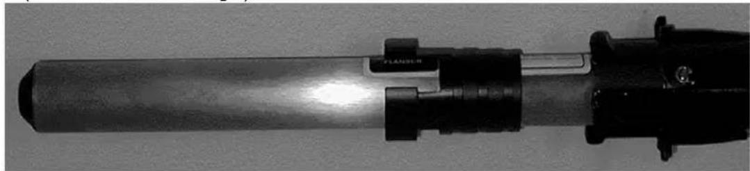
Adjusting Head Height.
Depending on the media type and media thickness used, it is possible to adjust the printer's printhead height accordingly 1.5 mm to 2.0 mm ( ± 0.15 mm).

natural_image
Close-up of a mechanical assembly with two views showing internal components and arrows indicating direction (no visible text or symbols)The head height can be adjusted using the lever on the left side of the head (please refer to the picture mentioned above).
When the lever is put in horizontal position (turn counter clockwise) the head is in his highest position : 2.0 mm
When the lever is turned clockwise, the head is in his lowest position : 1.5 mm.
The lever can only be put in two positions, there are no intermediates.
Typical use :
| LOW | HIGH |
| Photo quality output on photo paper type media(Mutoh Photo Great Piezo Media, Paper, Vinyl, Synthetic paper,...) | Thick media or media with fibres (Fabrics) which may touch the printhead during printing.(Canvas, Art Paper, Cardboard,...) |
!IMPORTANT
- Don't use media that is creased, blemished, torn or curled.
- Problems caused by using media other than that specified by Mutoh will not be covered by warranty. Always use cut media or roll media specified by Mutoh
- Temperature and humidity suitable for printing are shown below. We recommend setting up in an environment that can be air conditioned in order to maintain constant temperature and humidity.
| Temperature | 10°C to 35°C (16°C to 25°C for assured printing accuracy)Variation rate: Not more than 2°C per hour |
| Humidity 35% | to 80% (50% to 60% for assured printing accuracy) with no condensationVariation rate: Not more than 5% per hour |
- The absolute dimensions of printing media will be changed by variations in temperature and humidity. Therefore, printing media such as tracing media and high quality media that are readily susceptible to the effects of environmental changes should be acclimatized to the environment for about 30 minutes before printing. This acclimatization is called seasoning. Inadequate seasoning may cause the printing media to slip, crease or jam. It also affects the printing quality.
- With media recommended by Mutoh, you should be aware that a 1% variation in humidity may cause the media to expand or contract by the proportions shown below.
| Type of Media Rate of Dimensional Change | |
| Good quality media 0.018% | |
| Double-matte polyester film 0.0012% | |
- Oil from your skin may interfere with the way the ink sits on the media so you should wash your hands thoroughly before handling the media.
- If media that is larger than the prescribed size is used, the result of the printing may be affected by the media touching the floor during printing.
- Don't leave media loaded in the printer for a long period. This may cause the media to curl, lift up or jam. (This should be avoided especially in winter, dry periods and for formal printed output.)
• Media has a printing surface and non-printing surface. Printing on the non-printing surface may cause blurring or blemishes.
Loading Cut Media
Step 1
Open the cover, check that head is in a position where it will not touch the media keeper blade and put the hold lever up.
Step 2 Selecting media
Press the [MEDIA] key on the Control panel to light the Sheet media LED.
Step 3 Loading media
Insert seasoned media between the pressure roller and the drive roller.
Step 4
Align the right edge of the media with the middle of the guide line (holes).
flowchart
graph TD
    A["Roll"] --> B["Sheet"]
    B --> C["Take-up"]
    style A fill:#f9f,stroke:#333
    style B fill:#ccf,stroke:#333
    style C fill:#cfc,stroke:#333
text_image
Diagram showing hands operating a machine with labeled buttons and a pointer indicating 'C25'!IMPORTANT
- The guide line (holes) is a guide There is a possibility of a media jam if the pressure roller is not holding the left edge of the media and the pressure roller is near the right edge. Either hold the left edge of the media completely with the pressure roller or slide it so that pressure roller is about 5 mm away from the right edge of the media and the right edge of the media is within 5 mm to the left or right of the guide line (holes).

text_image
Technical diagram showing three structural cross-sections with labeled components and annotationsStep 5
Put the hold lever down.

natural_image
Technical line drawing of a printer or printer with a paper airplane being inserted (no text or symbols present)
NOTE
- Remove the roll media and scroller from the main unit before using.
- Don't load the media slantwise. The media size may be misidentified and the printing will not be normal.
- If the roll media lamp is lit by the Control panel setting, a "Roll media end" error may appear and printing will not terminate normally or the media may be cut.
- Apart from the maximum size that may be loaded, cut media can be loaded either longitudinally or laterally.
• Media has a printing surface and non-printing surface. Printing on the non-printing surface may cause blurring or blemishes. The printing surface is usually lighter.
Step 6
Close the cover. The head will move automatically to detect the size of the media.
Step 7 Removing the media
To remove the media, open the cover and put the hold lever up, then remove the media without touching the media keeper blade.

text_image
Con f i rm Paper r K i nd P l o t O K
natural_image
Illustration of a hand using a tool to adjust or install a cylindrical device (no text or symbols visible)
NOTE
- Don't put the hold lever up while the head is moving (during printing, media detection, media cutting, cleaning, etc.)
- When putting the hold lever up to load media, etc., make sure the head is in the stand-by position (maintenance position). The lever can not be put up if the head is not in the stand-by position.
- Don't move the head while the hold lever is up. The head may contact the media keeper blade.
Loading Roll Media
Step 1:
Open the cover, check that the head is in a position where it will not touch the media keeper blade and put the hold lever up.
Step 2: Selecting the media
- Press the [Media] key to select between cut-sheet or roll media.
- By pressing the key you will see the LED alternate between the two choices. Now select roll.
text_image
MEDIA Roll Sheet Take-up
natural_image
Warning symbol of a light bulb inside a triangle (no text or numbers)Note :
When making the wrong choice by selecting cut-sheet when a roll is loaded, the printer will pull off the maximum cut-sheet length, searching the back edge. Finally the printer will report a media search error.
Step 3:
Take your roll of media.
Step 4:
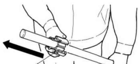
Remove the movable flange from the scroller by pulling it off.
natural_image
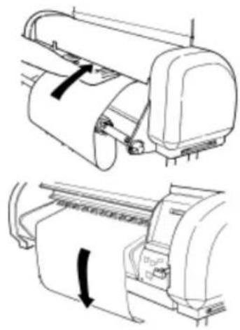
Line drawing of a person using a tool to lift a weight (no text or symbols)Step 5: Load the media over the scroller
Turn the roll media as shown in the diagram and pass it over the scroller until the media tube fits firmly over the fixed flange. Replace the movable flange on the scroller and fit it firmly into the media tube.

natural_image
Warning symbol of a light bulb inside a triangle (no text or numbers)Note:
- Do not drop the media roll over the scroller as this might damage the scroller end caps.
- All Mutoh recommended roll media are rolled up with the printable side facing the outside, so that you can load the roll media easily.
- When the cut sheet indicator light is ON when loading a roll, the printer will display a media search error after feeding the media for about 3m.
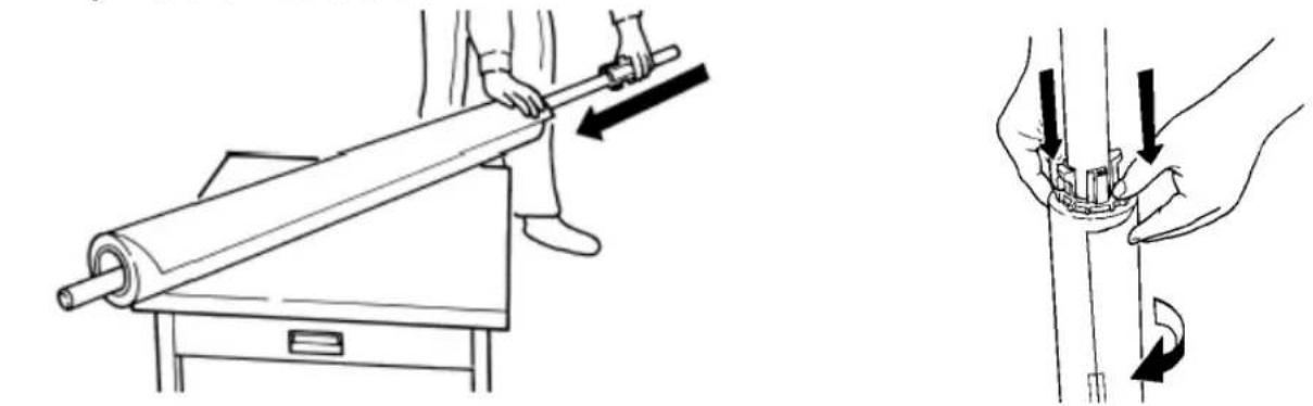
Step 6: Installing the scroller slip ring
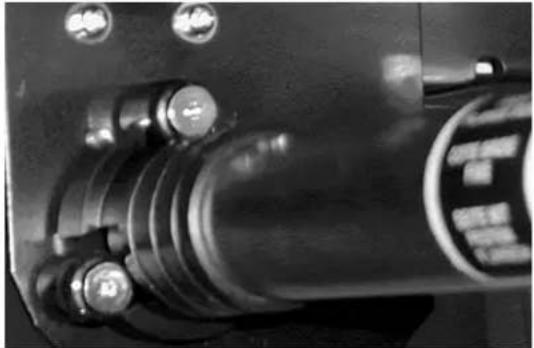
Install the scroller slip ring onto the scroller. Slide the scroller slip ring on the left side of the scroller (side with fixed flange).
natural_image
Close-up of a mechanical device with a transparent lever and black clamped components (no visible text or symbols)Step 7: Installing the scroller
Install the scroller as follows:
a) Stand at the back side of the printer, holding the scroller with the fixed flange side in your left hand.
b) Slide the scroller (left side) into the scroller receiver, as shown in the illustration.
c) Push the scroller (Right side - movable flange side) down into the right scroller receiver. You will notice it dropping nicely into place.
natural_image
Technical diagram showing mechanical assembly with tool and component alignment (no text or symbols)Step 8: Locking the scroller slip ring
Lock the scroller by sliding the scroller slip ring onto the scroller rollers. The scroller slip ring will prevent unwinding of the roll media from the scroller when roll media is still not loaded in the machine.
natural_image
Close-up of a mechanical component with multiple circular features and a central cylindrical body (no visible text or symbols)Step 9: Loading roll media
- Pull some media off the roll, feed it into the media feed gap and between the pressure rollers and the drive roller.
- Pull out the media at the front side and make sure at least 0.5 meters hangs out in front of the printer.
natural_image
Technical line drawing of a printer with paper roll and clasp mechanism (no text or symbols)
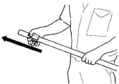
Caution:
- When you load roll media from the back, be careful not to hurt yourself by touching the pressure roll system.
Step 10: Checking the position of roll media
Turn the scroller by hand and wind up several turns of roll media. As you wind up the media, check the relative positions of the drive roller on the right and the right hand edge of the roll media. It is normal if with the roll media pulled tight, the portion that is being wound and the portion that was unwound are straight and the right hand side edge of the media is on the guide line. If this is not the case, adjust the position of the roll media in accordance with step 9.
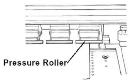
text_image
Pressure Roller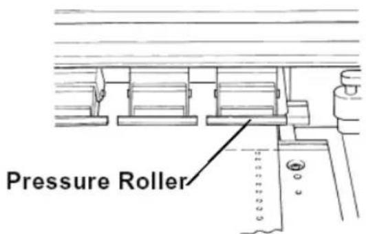
text_image
Pressure RollerGuide line (holes) can be seen Guide line (holes) is hidden
Step 11: Fine-tuning the roll media position
If the guide line (holes) can be seen, the roll media must be moved to the right. If the guide line (holes) is hidden, the roll media must be moved to the left.
- Turn the scroller receiver screw counterclockwise to move the roll media to the right (when standing in front of the printer).
- Turn the scroller receiver screw clockwise to move the roll media to the left (when standing in front of the printer).

natural_image
Illustration showing two-step instructions for adjusting a mechanical component, with no visible text or symbols.
Important:
• The guide line (holes) is a guide.
There is a possibility of a jam if the pressure roller is not holding the left edge of the media and the pressure roller is near the right edge. Either hold the left edge of the media completely with the pressure roller or slide it so that the pressure roller is about 5 mm away from the right edge of the media and the right edge of the media within 5 mm to the left or right of the guide line (holes).
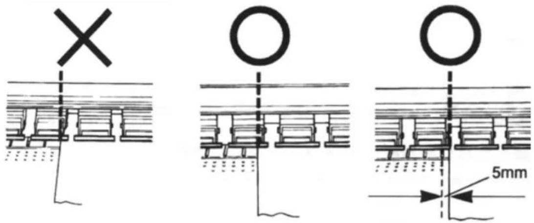
text_image
Technical diagram showing three structural cross-sections with symbols and dimension annotation of 5mm detailStep 12:
- Check if the roll media has been installed correctly.
- Lower the media hold lever and close the cover.
- The head moves automatically and detects the media size.
- The display will show the following message during loading:
ConfirmPaperKind
- After performing its media loading sequence (± 30 seconds) the printer displays the following message:
Plot OK

Important:
- If the roll media has not been fed straight or incorrectly, messages such as, “media error” or “media jam error” are shown on the display. If this is the case, reload the media following the instructions above.
Step 13:
During the media detection sequence, check if the media runs straight. After media detection, check the position of the right side of the roll media. If the position is almost on the same line as it was before closing the cover, media loading was performed successfully. If after the media detection sequence, the roll media position is not on the same position as it was before closing the cover, repeat the instructions from steps 8 and 9 for installing the media.

natural_image
Warning symbol of a light bulb inside a triangle (no text or numbers)Note:
Removing roll media
Step 1:
After printing, open the cover, tilt the media hold lever UP and wind up the roll media.
Step 2:
Stand behind the printer. Unlock the scroller receiver by pressing the lock lever down. You can now lift the right side of the scroller and remove it from the printer.

natural_image
Diagram of a mechanical joint or clamp mechanism with arrows indicating force direction (no text or symbols)Step 3:
Remove the roll media by gently pushing the roll media off the scroller via the moveable flange side.
At no times drop the scroller end-caps on the floor as this might damage the scroller end-caps and reduce media tracking or loading problems.
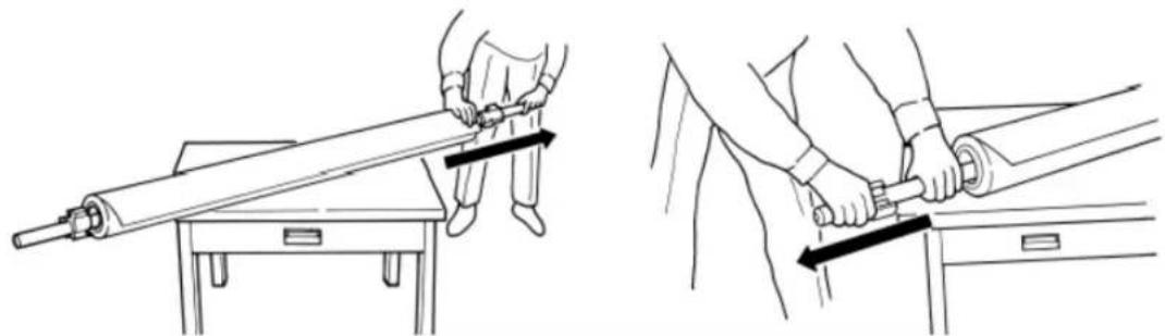
natural_image
Line drawings showing two different techniques for using a mechanical tool, with no visible text or symbols.Loading media in combination with the Roll Take-Up System.
Step 1 :
Open the cover and put the hold lever in the UP position by tilting it up(wards).
Step 2 : Selecting roll take-up system
- Press the Media-key to select media loading sequence with roll take-up system (Both LEDs ON).
- By pressing the key you will see the LEDs alternate between three choices (sheet, roll and take-up). Now select roll take-up loading sequence (both LEDs ON).
Step 3 :
Take an empty cardboard core. Slide the empty cardboard roll over the scroller of the roll take-up system.

Note :
Notice that one flange is fixed. A warning sticker is attached near the flange. Do not remove this flange.
natural_image
Pure mechanical shaft diagram without any text, numbers, or symbols
flowchart
graph TD
    A["Roll"] --> B["Sheet"]
    B --> C["Take-up"]
Step 4 :
Take your roll of media.
Step 5 :
Remove the moveable flange from the scroller by pulling it off.
natural_image
Illustration of a hand holding a cylindrical object with a directional arrow indicating motion (no text or symbols)Movable Flange
Step 6 : Load the media onto the scroller.
Feed the scroller through the media core.
Gently but firmly press the roll media over the fixed flange.
Slide the moveable flange over the scroller and firmly press the flange inside the roll media core.

natural_image
Illustration of a person using a tool to lift a large cylindrical object, with no visible text or symbols.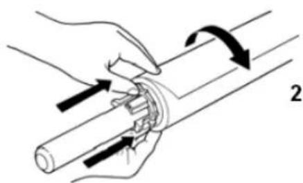
natural_image
Illustration of a hand holding a cylindrical object with arrows indicating motion or force direction (no text or symbols)1 = Fixed flange
2 = Media winding direction

Note :
- Do not drop the media roll over the scroller as this might damage the scroller end caps. Damaged end caps may cause media tracking problems.
- All Mutoh recommended roll media are rolled up with the printable side facing the outside, so that you can load the roll media easily.
Step 7: Installing the scroller slip ring
Install the scroller slip ring onto the scroller. Slide the scroller slip ring on the left side of the scroller (side with fixed flange).
natural_image
Close-up of a mechanical device with a cylindrical shaft and black clamped components (no visible text or symbols)Step 8 : Installation of the scroller.
Install the scroller as follows :
a) Stand at the back side of the printer, holding the scroller with the fixed flange side in your left hand.
b) Slide the scroller (left side) into the scroller receiver, as shown in the illustration.
c) Push the scroller (Right side – movable flange side) down into the right scroller receiver. You will notice it dropping nicely into place.

natural_image
Technical diagram showing mechanical assembly with tool and hand positions (no text or symbols)Step 9: Locking the scroller slip ring
Lock the scroller by sliding the scroller slip ring onto the scroller rollers. The scroller slip ring will prevent unwinding of the roll media from the scroller when roll media is still not loaded in the machine.

natural_image
Close-up of a mechanical component with bolts and a central shaft (no visible text or symbols)Step 10 : Loading roll media.
Pull some media off the roll, feed it into the media feed gap and between the pressure rollers and the drive roller.
Pull out the media at the front side and make sure at least 0.5 meters hangs out in front of the printer.

natural_image
Technical line drawing of a printer with paper roll and clasp mechanism (no text or symbols)
Caution :
When you load roll media from the back, be careful not to hurt yourself by touching the pressure roller system.
Step 11 : Checking the position of roll media.
Turn the scroller by hand and wind up several turns of roll media. As you wind up the media, check the relative positions of the drive roller on the right and the right hand edge of the roll media. It is normal if with the roll media pulled tight, the portion that is being wound and the portion that was unwound are straight and the right hand side edge of the media is on the guide line. If this is not the case, adjust the position of the roll media in accordance with step 9.

text_image
Pressure Roller Pressure RollerGuide line (holes) can be seen Guide line (holes) is hidden
Step 12 : Fine-tuning the roll media position.
If the guide line (holes) can be seen, the roll media must be moved to the right. If the guide line (holes) is hidden, the roll media must be moved to the left.
- Turn the scroller receiver screw counterclockwise to move the roll media to the right (when standing in front of the printer).
- Turn the scroller receiver screw clockwise to move the roll media to the left (when standing in front of the printer).

natural_image
Illustration of a hand adjusting a mechanical component with directional arrows indicating movement (no text or symbols)
Important:
• The guide line (holes) is a guide.
There is a possibility of a jam if the pressure roller is not holding the left edge of the media and the pressure roller is near the right edge. Either hold the left edge of the media completely with the pressure roller or slide it so that the pressure roller is about 5 mm away from the right edge of the media and the right edge of the media within 5 mm to the left or right of the guide line (holes).
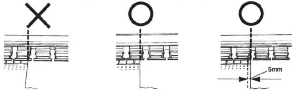
text_image
Technical diagram showing three structural components with cross, circle, and 5mm dimension标注Step 13 :
- Before lowering the media hold lever, hold the media on the front side and turn the media feeding scroller slightly backward, making sure that there is an even tension across the full media width.
• Lower the media hold lever and close the cover. - The head moves automatically and will search for the left and right edge of the media being loaded.

Important :
If the roll media has not been fed straight or incorrectly, messages such as “Stuck Media error” or “Take out paper” are shown on the display. If this is the case, reload the media following the instructions mentioned above.
Step 14 :
In the MENU "Function" of your printer, set media cut to OFF.
Loading the Media Loading Roll Media
Step 15 :
Feed the media forward by pressing the SHIFT & ADVANCE keys simultaneously until the media reaches the cardboard core on the take-up system.
Step 16 :
Fix the media on the cardboard core by means of self-adhesive tape strips in the middle and on the left and right side.
natural_image
Technical line drawing of a mechanical device with no visible text or symbols
Note :
First attach the middle of the media on the cardboard core to avoid slipping of the media.
Step 17 :
Feed the media slightly forward (using SHIFT & ADVANCE) and wind it up on the take-up system.
Now you are ready to start printing.
Once the printer has printed as much as shown on the figure below, the sensors will be activated and the take-up system will start winding up the media.

natural_image
Line drawing of a large cylindrical printer or paper roll with wheels and a central scroll (no text or symbols visible)Once your print is finished and dry you can wind up your print via a manual feed button. If you want to sheet off the print push the cancel button for 2 seconds and confirm the sheet-off request.
If you want to wind up or wind off your print you can do this via the forward / reverse button.
Using Pre- and Post-Heaters.
Use the Pre- and Post-heater for uncoated or slow-drying media. With the Heaters you can get a wider range of media compatibility.
When using the heaters set it on the maximum temperature. (50°C)

Important :
Depending on the use of media, it is possible that media starts to curl. If this is the case, lower the temperature.

Important :
Depending on the use of media, it is possible that media starts to curl. If this is the case, lower the temperature.
Making a Test Print
Make a test print to verify that the printer is working properly.
Step 1
Open the cover and check that the hold lever is up.
Step 2
Press the [MEDIA] key to light the Sheet media LED. (Cut media is selected)
Step 3
Load an A3 size sheet of cut media and put the hold lever down.
Plot OK
Step 4
After initialization has finished, press the [Test Print] key (Quality/speed, key) while you are pressing the [shift] key.(Test print: pale blue)
Printing
Test print sample (paste your test print on this page)

text_image
1 2 3 4 5 6 7 8 A B C D E F G H I J
NOTE
- If you are unable to make a test print like the above sample, contact your local Mutoh dealer.
Connecting the Interface Cable
CAUTION
- Make sure the power to the printer and to the computer is switched off when you connect the printer and computer.
NOTE
- For optimum output, please use a cable recommended by Mutoh. If some other cable is to be used, select one by referring to "Centronics (Bi-directional Parallel Interface: IEEE1284 compatible) Specifications" on page 213.
The printer can use the Centronics interface (IEEE1284 compatible, Nibble, ECP). Connect to the printer with an interface cable (option) for the connection system you will use. Connect to the host computer with another interface cable.
NOTE
- The use of an unnecessarily long cable may affect data transmission. Interface cables should be as short as possible.
- An Ethernet board RJ-ETH14TX (for networking) is available as an optional extra. Installation is explained "Installation of options, Network interface board installation" on page 166.
ToReceive Data from the Computer
First, prepare the printer to receive data from the computer. The conditions for connecting the printer and computer must be aligned beforehand on the printer side and on the computer side. This is called set-up.
The basic printer set-up for receiving data from a computer involves the following four types of settings.
| Command Settings Specifies the type of online commands | |
| Setting the Position to Start Writing | Selects the position (initial position) to begin writing after the printing media has been mounted |
| Centronics Settings Settings related to the Centronics interface (IEEE1284 compatible, Nibble, ECP) | |
| Network Settings Specified if an optional network interface (Ethernet) is to be used. | |
Input Port
Input port means the type of interface port. Falcon Outdoor input ports are set as follows.
| Input Port | Type of Interface |
| Port 1 | Centronics (IEEE1284 compatible, Nibble, ECP) |
| Port 2 | Option board (empty) |
Online Set-up
There are two types of online-related settings: Centronics settings with respect to the computer and Centronics connection, and network settings with respect to the computer and network connection.
Settings at the time of shipping by Mutoh
| Centronics Settings | Network Settings (option: empty) | |
| Mode Bitronics | IP address 192.034.043.015 | |
| Timing | AB system | |

NOTE
- If values other than those set at the time of shipping from Mutoh are used, be sure to refer to "Centronics Settings" on page 136 or "Network Settings" on page 138.
Command Set-up (User Settings)
Each user will specify the online commands from the computer and the command conditions.
Commands
The type of command for verification is the MH-GL system (MH-GL/GL2, MH-GL2, RTL-PASS).
MH-GL system commands (emulation of Hewlett-Packard printer commands)
Settings at the time of shipping by Mutoh
| Command Item |
| Initial position P1 |
| Terminator Normal |
| Resolution 360 dpi |

NOTE
- If values other than those set at the time of shipping from Mutoh are used, be sure to refer to "Command Settings" on page 113.
Printing the Setup List
In online printing was possible, try printing the Setup List.
Step 1
Open the cover and make the hold lever is up.
Step 2
Press the [MEDIA] key and light the Sheet media LED.
Step 3
Load an A4 size sheet vertically.
Step 4
Select the printing of setup List by pressing the [Setup Print] key (VACUUM, key) while you are pressing the [Shift] key.
Printing
Step 5
The setup sheet is printed.
!IMPORTANT
- Since this setting detail sheet will be needed for future maintenance and repair, paste the completed print on this page.
Sample Print
Setup List
| Panel Plot Mode = Draft Density = 360dpi(x) 720dpi(y) Roll/Cut = RollingU Media = Thin | Information SerialNo. = CM6A000011 Type = Inkjet !Error! PROM = V 1.11 0:None [ ] 3:None [ ] NVRAM = V 1.00 1:None [ ] 4:None [ ] Opt.Memory = 32MB 2:None [ ] 5:None [ ] | |
| Command Command = RTL-PASS PositionOffset Plot Area = Normal X = 0mm Position = PI Y = 0mm Terminate = Normal Resolution = 360dpi OnlineTimer = 90sec Overwrite = Last | Function InkDryTime = 30sec Dist.Adj Halftone = $peed DataX = 1000.00 KCMY->XMY = No RealX = 1000.00 CMY->BLACK = Yes BandAjust = 0.00% KYCMYK = Off Scale = 100.0% Mirror = Off Direct. = Command CutPos. = Data MediaCut = Off Copy = l InkDensity = Normal | |
| Centro Mode = Bi Centro Timing = A-B | ||
| Network IP Address = 172.016.199.025 | Utility ErrorDisplay = Off | |
!IMPORTANT
- Cloth must be cut manually (refer to "Function Settings: Media Cut" on page 130.)
This function is used for manually cutting roll media (such as cloth) that can not be cut automatically after it has been printed.
Step 1 Specifying manual cutting
Refer to "Function settings: Media cut" on page 130.
Medi a Cut : manua
Step 2
Preparations for printing (load media, online settings, etc.) must be made beforehand.
Print any image or picture.
Step 3
When the printer has finished printing, the media will be fed out to the position for manual cutting.
Manual Cut Paper
Step 4
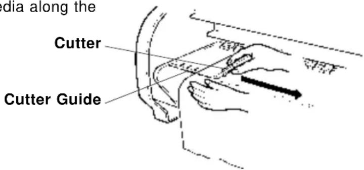
Use a cutter to cut the media along the cutter guide.
text_image
edia along the Cutter Cutter GuideStep 5
Press the [ENTER] key on the control panel
P I o t O K
Direct Access Keys
In this section we explain about direct access key operations that are often used to enable printer functions to be used effectively.
| Specifying the Media to be used | PAGE 74 |
| Specifying the Resolution | PAGE 75 |
| High Quality Printing, Normal Printing, High Speed Printing | PAGE 77 |
| Head Cleaning | PAGE 78 |
| Cutting the Media | PAGE 79 |
| Making a Test Print and Setup List | PAGE 80 |
| Media Feed | PAGE 81 |
| Reverse Media Feed | PAGE 82 |
| Fine Adjustment of Print Quality | PAGE 83 |
Specifying the Media to be Used

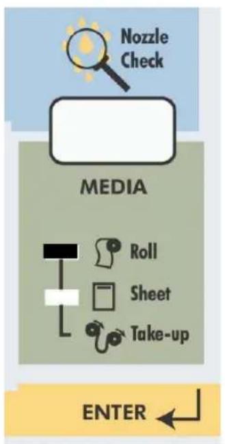
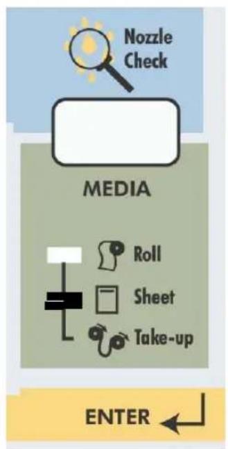
Here we select whether we will use roll media or cut media as the media to be loaded in the Falcon Outdoor printer.
flowchart
graph TD
    A["Media"] --> B["Roll"]
    A --> C["Sheet"]
    A --> D["Take-up"]
    A --> E["Nozzle Check"]
    F["ENTER"] --> A
For cut media
text_image
Nozzle Check MEDIA Roll Sheet Take-up ENTERFor roll media

flowchart
graph TD
    A["Nozzle Check"] --> B["MEDIA"]
    B --> C["Roll"]
    B --> D["Sheet"]
    B --> E["Take-up"]
    C --> F[" "]
    D --> G[" "]
    E --> H[" "]
    style A fill:#f9f,stroke:#333
    style B fill:#ccf,stroke:#333
    style C fill:#cfc,stroke:#333
    style D fill:#fcc,stroke:#333
    style E fill:#cff,stroke:#333
    style F fill:#ffc,stroke:#333
    style G fill:#cfc,stroke:#333
    style H fill:#fcc,stroke:#333
Roll with Take-Up
! IMPORTANT
- If roll media is loaded while cut media is selected on the panel, the media will be fed out in order to detect the end of the sheet. Always make sure that the type of media specified on the panel matches the media that is loaded.

NOTE
- Ink drying times differ according to the type of media. 30 seconds is specified for Falcon Outdoor printers when shipped by Mutoh but this needs to be specified to correspond to the media. The ink drying time specifies the period from the end of printing until the media is fed out (and roll media is cut) in order to allow the ink to dry. For more detail, please refer to "Function settings: Ink Dry Time" on page 122.
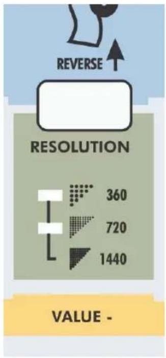
Specifying the Resolution

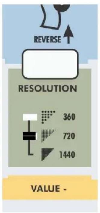
The resolution of the Falcon Outdoor at the time of output can be selected as 360 dpi, 720 dpi or simulated 1440 dpi (RTL-PASS).
720 dpi or simulated 1440 dpi gives high grade printing at near photo quality.
Specify resolution at the time of graphic data output.
When the Low LED is lit, 360 dpi is selected. When the High LED is lit, 720 dpi is selected. When both the Low and High LEDs are lit, simulated 1440 dpi is selected.
Press the [RESOLUTION] key. If the current resolution setting is 360 dpi, then the High LED will be lit and the setting will change to 720 dpi. If the current resolution setting is 720 dpi, then the Low LED and the High LED will be lit and the setting will change to simulated 1440 dpi. If the current resolution setting is simulated 1440 dpi, then the Low LED will be lit and the setting will change to 360 dpi.
text_image
REVERSE RESOLUTION 360 720 1440 VALUE -Resolution For 360 dpi

text_image
REVERSE RESOLUTION 360 720 1440 VALUE -Resolution For 720 dpi
text_image
REVERSE RESOLUTION 360 720 1440 VALUE -Resolution
For simulated 1440 dpi
□ : Lit
■ : Not lit

NOTE
- High quality printing is obtained at high resolutions of 720 dpi and simulated 1440 dpi but the printing time is longer than at 360 dpi.
- If high resolution image data such as 720 dpi or 600 dpi is printed at 360 dpi, it may not be possible to obtain adequate printing results.
High Quality Printing, Normal Printing, High Speed Printing

According to the printing environment to be used, three speeds can be specified for a Falcon Outdoor printer.
In changing them, you should consider the resolution and printing time required for the printing.
By changing the printing mode, printing may be high quality, normal or high speed.
* High Quality Printing Mode: The high quality lamp is lit. The printing is better than normal printing mode but the printing speed is slower.
* Normal Printing Mode: This is the ordinary printing mode. The normal printing mode lamp is lit.
* High Speed Printing Mode: Printing speed has priority. The high speed lamp is lit. Use it for check printing.
When the printing mode is altered, the LED of the selected mode lights up.
Step 1
Press the [QUALITY / SPEED] key once or twice until LED for the desired printing mode is lit.
Step 2
When the printing mode changes, the LED of the selected mode changes to lit.

□ : Lit
■ : Not lit
For high quality mode For normal mode For high speed mode
Head cleaning is a function that cleans the head face and nozzles. Head cleaning should be carried out if the printing is more faint or lacking in detail compared with the previous printing.
!IMPORTANT
- When printing for a long period under dusty conditions, dust collects in the maintenance section and inspection and maintenance may be required.
- A paper jam or paper rubbing on the head must be investigated.
Step 1
With no paper loaded and the lever down, press and hold the [CLEANING] key for at least two seconds.
Step 2
Head cleaning proceeds.

NOTE
- Powerful head cleaning will be implemented if the [CLEANING] key is pressed after two pages or less have been output since the last head cleaning operation was performed (or since power was switched on if there has been no head cleaning since power was switched on). (However, if the cover is opened during cleaning, the cleaning will be normal cleaning.)
Powerful cleaning should be done if there is severe faintness or lack of detail. After three or more pages, normal cleaning will be carried out. - If several cleaning do not eliminate the faintness or lack of detail, refer to "When trouble strikes" and carry out the measures and then contact your local Mutoh dealer.
- Make sure the hold lever is down before pressing the [CLEANING] key.
- Head cleaning can also be done with media loaded. However, if the media is too wrinkled it may touch the head so we recommend that head cleaning be done with the media removed.

NOTE
- When a new roll of media is mounted, the leading edge of the media may not be straight. In this case, the leading edge of the media should be cut.
The [CANCEL] key can be switched between the cancel function and the media cut function, depending to the status of the printer. You should use it in accordance with your need.
| Printer Status | Result of Pressing the [CANCEL] key | |
| Before data reception D | ATA LED off Media is fed then cut | |
| During data reception D | ATA LED on Input data is cancelled | |
| During data processing | DATA LED flashing Processed data is cancelled | |
| During printing During | head movement Printing is forcibly stopped and the data is cancelled | |
Use the cut function if you want to cut the leading edge of the roll media. The cut function can be used if roll media is loaded and data is not being received or processed.
Step 1
Make sure that roll media is loaded and data is not being received or processed. (DATA LED is not lit.)
Step 2
Press the [CANCEL] key.
Step 3
Roll media is fed then cut.
These are prints of the current status of the printer. Check by printing out the following two types of print.
Test print: This checks whether the printer is fully operational by making a print.
Setup List print: This prints out details such as printer online settings.

NOTE
- It is useful to keep the Test print and Setup List print in this book in case trouble occurs later. Keep the Test print on page 66 and the Setup List print on page 70.
Step 1
Load an A3 size sheet of media and put the hold lever down.
Step 2
For the test print, press the [Test Print] key (Quality/speed key) while you are pressing the [Shift] key.
For the Setting details print, press the [Setup Print] key (VACUUM key) while you are pressing the [Shift] key.
Step 3
The Test print or Setup List print are output automatically.
Sample of Setup List print
Setup List
Panel
Plot Mode = Draft
Density = 360dpi(X)
720dpi(Y)
Roll/Cut = RollingUp
Media = Thin
Information SerialNo. = CM6A000011 Type = Inkjet !Error! PROM = V 1.11 0:None [ ] 3:None [ ] NVRAM = V 1.00 1:None [ ] 4:None [ ] Opt.Memory = 32MB 2:None [ ] 5:None [ ]
Command Command = RTL-PASS PositionOffset Plot Area = Normal X = 0mm Position = PI Y = 0mm Terminate = Normal Resolution = 360dpi OnlineTimer = 90sec Overwrite = Last
Function InkDryTime = 30sec Dist.Adj Halftone = $peed DataX = 1000.00 KCMY->KMY = No RealX = 1000.00 CMY->BLACK = Yes BandAjust = 0.00% KYCMYK = Off Scale = 100.0% Mirror = Off Direct. = Command CutPos. = Data MediaCut = Off Copy = 1 InkDensity = Normal
Centro Mode = Bi Centro Timing = A-B
Network IP Address = 172.016.199.025
Utility ErrorDisplay = Off
If roll media is being used, the media will be fed in the normal direction while the [Shift] key and [Media Feed] key are pressed. Roll media will not be fed while data is being received or processed. Media is not fed while cut media is in use.
Step 1
The media feed function can be used only when roll media is loaded and data is not being received.
Step 2
Feed roll media by pressing the [Media Feed] key (MENU, Menu Down key) while you are pressing the [Shift] key.
Step 3
Release the [Shift] key and [Media Feed] key (MENU, Menu Down key) when the roll media has been fed to the desired position.

NOTE
- If the printing surface of the roll media that is to be used for printing is dirty, press the [Media Feed] key (MENU, Menu Down key) while pressing the [Shift] key to feed the media until the printing surface is clean. Then use the [CANCEL] key to cut off the dirty media.
Reverse Media Feed
If roll media is being used, the media will be fed in the reverse direction while the [Shift] key and [Resolution] key are pressed. Roll media will not be fed while data is being received or processed. Media is not fed while cut media is in use.
Step 1
The reverse media feed function can be used only when roll media is loaded and data is not being received.
Step 2
Feed roll media (in reverse direction) by pressing the [Resolution] key while you are pressing the [Shift] key.
Step 3
Release the [Shift] key and [Resolution] key when the roll media has been fed to the desired position.

Important :
Before using the reverse media feed option be sure the media is dry. Otherwise, the outprint could get damaged.
Fine Adjustment of Print Quality
text_image
Shift + Function +Although your printer was adjusted for optimum quality at the time of shipment, the printing quality may vary according to the type of media. In such cases, a accuracy adjustment plot of printing quality can be made with the following procedure.
!IMPORTANT
- Unless you understand this function fully, there is a risk that the fine adjustment may make the quality even worse. Normally, no adjustment should be made.
- You need a sheet of media of A3 size or larger, mounted vertically for the fine adjustment. If a sheet of media smaller than A3 is loaded, it may not be possible to obtain a proper print.
Step 1
With an A3 or larger sheet of media loaded vertically, press the [Fine Adjustment] key (CLEANING, Menu Up key) while you are pressing the [Shift] key.
Step 2
The accuracy adjustment plot is printed automatically.
P I o t O K
Accur. Adj P l ot
Sample Accuracy Adjustment Plot
Look at pattern A on your print. Use the [VALUE +] and [VALUE -] keys to enter the number of a line with no offset.
PatternA: 4
Step 4
Press [ENTER] key to confirm the value specified for pattern A.
PatternA: 6
Step 5
Look at pattern B on your print. Use the [VALUE+] and [VALUE-] keys to enter the number of a line with no offset.
PatternB: 4
Step 6
Press [ENTER] key to confirm the value specified for pattern B.
PatternB: 5
Step 7
Look at pattern C on your print. Use the [VALUE +] and [VALUE -] keys to enter the number of a line with no offset.
Pattern C: 4
Step 8
Press [ENTER] key to confirm the value specified for pattern C.
PatternC: 4
Step 9
Permanent display is restored.
P I o t O K

NOTE
- The accuracy adjustment adjusts the color head reciprocal printing position and the black head reciprocal printing position as well as aligning the pointing position between the color head and the black head.
- If the cancel key is pressed during fine adjustment printing or it is interrupted by raising the hold lever, there will be no input display screen
- Unless the exclusive media specified by Mutoh is used, the ink may run and proper adjustment will not be possible. Exclusive media specified by Mutoh should be used for printing quality adjustment.
Menus
In this section, we give a summary explanation about menus for the practical use of the printer functions.
Menu mode Operation PAGE 88
Menu Structure PAGE 90
Shift to setting mode for practical functions than cannot be set up by direct access keys.
Step 1
Press the [MENU] key to shift to setting mode. Direct access key operation does not work.

Step 2
By pressing the [MENU] key, the control panel keys take on the functions shown in yellow. Press the Select setting mode by pressing the [Menu Down] key or the [Menu Up] key.
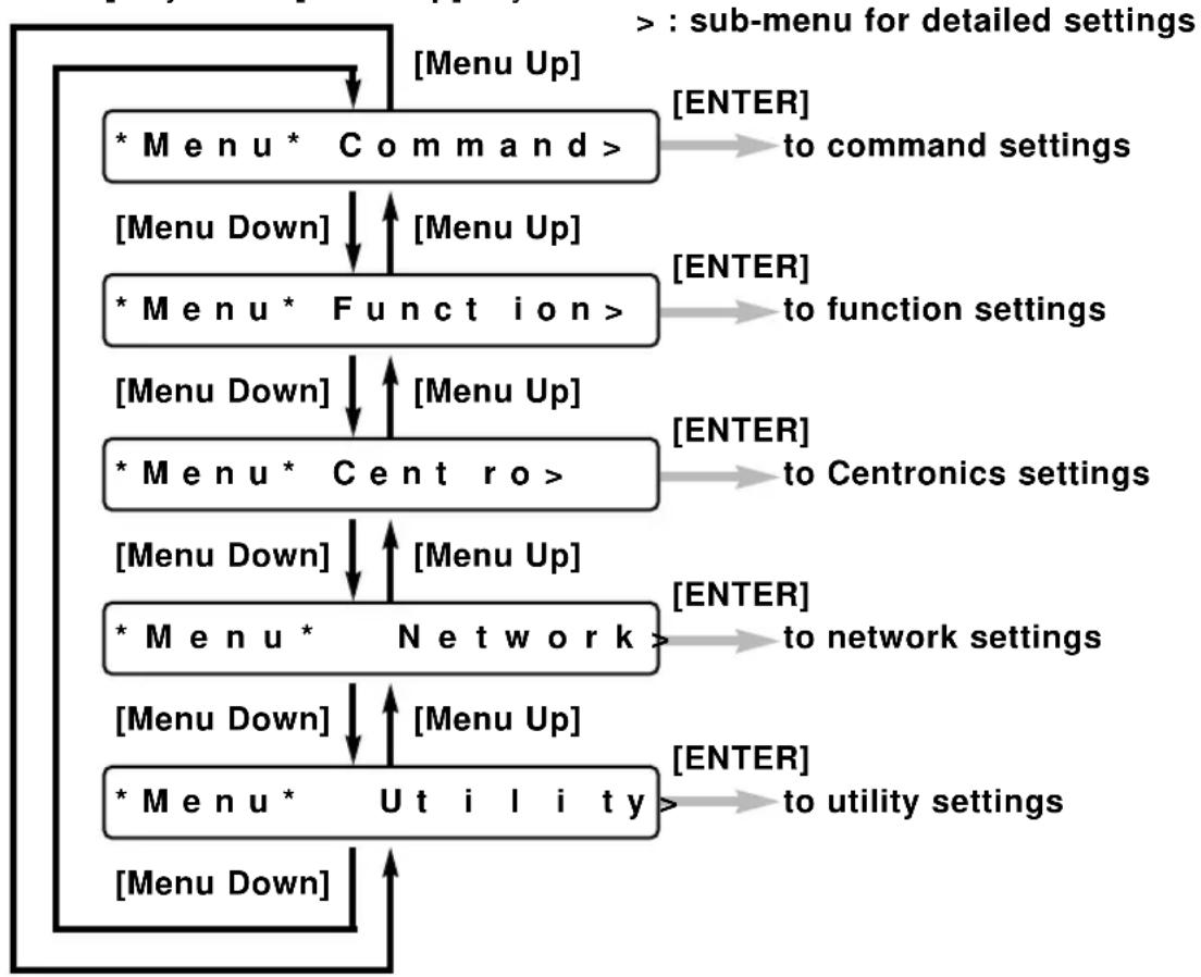
flowchart
graph TD
    A["* Menu * Command >"] -->| [Menu Up] | B["* Menu * Function >"]
    B -->| [Menu Down] | C["* Menu * Centro >"]
    C -->| [Menu Down] | D["* Menu * Network >"]
    D -->| [Menu Down] | E["* Menu * Utility >"]
    E -->| [Menu Down] | F["> : sub-menu for detailed settings"]
    F --> G["[ENTER"] to command settings]
    F --> H["[ENTER"] to function settings]
    F --> I["[ENTER"] to Centronics settings]
    D --> J["[ENTER"] to network settings]
    D --> K["[ENTER"] to utility settings]
Step 3
* Press [ENTER] to proceed with the setting
* The part of the display that is flashing can be altered. To change a setting, select a value by pressing the [VALUE+] or [VALUE-] keys.
* The setting will not change unless the [ENTER] key is pressed.
* If the set-up is complete, press the [Menu Up] key. If there is no key operation in Menu setting mode for 3 minutes, Direct access key input standby (permanent display) is restored.
Menu Levels
* Menu * Command >
| Command | RTL-PASS / MH-GL, GL2 / MH-GL2 |
| Plot Area | Normal / Expand |
| Position | P1 / LL / Full |
| Terminat | Special / Normal |
| Resolut. | 300 dpi / 360 dpi / 720 dpi |
| Online Timer | Off / 10 sec to 30 sec to 800 sec |
| Overwrite | Last / Mix |
| OriginReset | No/Yes |
* Menu * Function >
| Ink Dry Time | 0 sec to 5 sec to 30 sec to 60 min |
| Halftone | Speed / Quality / Thin |
| KCMY -> KMY | Yes / No |
| CMY->BLACK | No / Yes |
| KYCMYK | No / Yes |
| Scale | 25% to 100% to 400% |
| Mirror | Off / Y On |
| Direct. | Command / MAX-MIN |
| Cut Pos. | Data / Standard |
| Media Cut | Auto / Manual / Off |
| Copy | 1 to 99 |
| Ink Density | Normal/ Micro |
| Dist. Adj. | No / Clear / Change / Confirm |
| StepAdj | Change/Clear |
* Menu * Centro >
| Mode | Centro / Bitro |
| Timing | A-B / B-A |
* Menu * Network >
IP Address 000.000.000.000 to 192.034.043.015 to 255.255.255.255
* Menu *
Utility>
Error Display On / Off
Initial OK / No
All OK / No
Command OK / No
Functi. OK / No
Centro OK / No
Network OK / No
Dump Start-End / All (cancel with [CANCEL] key
Wash
Clean Normal / Powerful
Fill Yes / No
Ink Change Yes / No
Maintenance Rec.
When You Want to Do This
This section makes it easy for you to look up what sort of function to use when you want to do a particular sort of operation. It asks the questions and then tells you on which page of which User Guide you can find the answers.
When You Want to Do This
PAGE 93
To use roll media efficiently
| Question Answer | Explanation Operation | ||
| I want to print without making waste spaces on the media. | Set “Direction” to “MAX-MIN” in “Function” settings. | Page 104 | Page 126 |
| I want to make a print that aligns the data with spaces. | Set “Direction” to “Command” in “Function” settings. | Page 104 | Page 128 |
| I want to cut the media to the size that has been printed. | Set “Cut Position” to “Data” precedence in “Function” settings. | Page 105 | Page 129 |
| I want to cut the media to the standard size. | Set “Cut Position” to “Standard” size in “Function” settings. | Page 105 | Page 129 |
| I want to make a series of prints on one sheet without cutting. | Set “Media Cut” to “Off” in “Function” settings. | Page 106 | Page 130 |
To speed up printing time
| Question Answer | Explanation Operation | ||
| If I want to shorten the time between finishing the print and cutting the roll media? | Change “Ink Dry Time”. | Page 103 | Page 122 |
| If I want to print quickly even if resolution is reduced? | Light up the Low LED by pressing the [RESOLUTION] key. | Page 75 | Page 75 |
| If I want to print quickly even if graphic quality is reduced? | Set “Harftone” to “Speed” diffusion for the user number that you want to change. | Page 103 | Page 124 |
| If I want to print faster without reducing resolution or quality? | Change the interface connection (from Centronics to Network) | Page 107 | Page 138 |
To improve printing quality
| Question Answer | Explanation Operation | ||
| If I want to give priority to quality rather than speed? | Light up the Quality LED by pressing the [QUALITY / SPEED] key. | Page 77 | Page 77 |
| If I want to give priority to graphic quality rather than speed? | Set “Halftone” to “Quality” diffusion for the user number that you want to change. | Page 103 | Page 124 |
To connect with Centronics
| Question Answer | Explanation Operation | ||
| If I want to have bidirectional communication with Centronics? | Change the Centronics mode setting to “Bi Centronics”. | Page 107 | Page 136 |
| If I want to change Centronics ACK/BUSY timing control? | Change “Timing” in “Centronics” settings. | Page 107 | Page 137 |
To connect with network (Ethernet)
| Question Answer | Explanation Operation | ||
| If I want to change the IP address? | Change “IP address” in “Network” settings. | Page 107 | Page 138 |
To cut roll media
| Question Answer | Explanation Operation | ||
| If I want to feed and cut the finished part of a print? | Check that printing data are not being received then feed the media by pressing the [MENU] key while you are pressing the [Shift] key and cut the roll media by pressing the [CANCEL] key. | Page 71 | Page 71 |
To place printed output in a specified position
| Question Answer | Explanation Operation | ||
| If I want to print in the middle of the page with maximum and minimum data values? | Change “Direction” to “MAX-MIN”. | Page 104 | Page 128 |
| If I want to print on media of a different size from that specified in the data. | Set “Scale”.*Examples of scales between standard sizes:A4 > A3, A3 > A2,A2 > A1, A1 > A0,B4 > B3, B3 > B2,B2 > B1, B1 > B0 : 141%A4 > B4, A3 > B3,A2 > B2, A1 > B1,A0 > B0 : 122%B4 > A3, B3 > A2,B2 > A1, B1 > A0 : 115%B0 > A0, B1 > A1,B2 > A2, B3 > A3,B4 > A4 : 86%A0 > B1, A1 > B2,A2 > B3, A3 > B4 : 81%A0 > A1, A1 > A2,A2 > A3, A3 > A4,B0 > B1, B1 > B2,B2 > B3, B3 > B4 : 70% | Page 103 | Page 126 |
| If I want to print with reversed data? | Set “Mirror” for the user number you want to change. | Page 104 | Page 127 |
| If I want to (re)nest my print data? | Use the "Origin Reset" combined with the backward feed. | Page 102 | Page 121 |
To use color effectively
| Question Answer | Explanation Operation | ||
| If I want to print after changing the graphic quality? | Press the [QUALITY / SPEED] key and select “Quality”, “Normal” or “Speed”. | Page 77 | Page 77 |
| Change “Halftone” There are three type of tone processing: “Speed” diffusion, “Quality” diffusion and “Thin” diffusion. | Page 103 | Page 124 | |
| If I want to print after changing the resolution. | Change “Resolution”. | Page 101 | Page 117 |
| If I want to print after mixing overlapping colors (over print)? | Change “Overwrite”. | Page 101 | Page 120 |
To check the status of the printer
| Question Answer | Explanation Operation | ||
| If I don't want non-problematical errors to be displayed? | Set “Error Display” to “Off” in “Utility” settings. | Page 108 | Page 140 |
| If I want to restore error display without switching off the power? | Set “Error Display” to “On” in “Utility” settings. | Page108 | Page 140 |
To use another type of ink
| Question Answer | Explanation Operation | ||
| If I want to change the type of ink? | Use “Ink Change” to change to another ink type | Page 109 | Page 159 |
To check printer set-up
| Question Answer | Explanation Operation | ||
| If I want to know what are the current printer settings? | Print the setup list print by pressing the [MEDIA] key while you are pressing the [Shift] key. | Page 70 | Page 70 |
| If I want to restore the original factory Command settings? | Initial “Command” under “Initial” in “Utility” settings. | Page 108 | Page 143 |
| If I want to restore the original factory Function settings? | Initial “Function” under “Initial” in “Utility” settings. | Page 108 | Page 145 |
| If I want to restore the original factory Function settings? | Initial “Centronics” or “Network” under “Initial” in “Utility” settings. | Page 109 | Page 147 |
| If I want to restore all of the printer's original factory settings? | Initial “All” under “Initial” in “Utility” settings | Page 108 | Page 141 |
Explanation of Functions
This section explains the content of each function in detail and gives the page number for you to look it up easily in the User Guide.
Understanding the Functions
PAGE 103
Understanding the Functions
Command Settings
| Name of Function | Reference Page |
| Command | Page 113 |
| This specifies the commands and conditions that are transferred from the computer. The following commands are supported:• RTL-PASS:• MH-GL, GL2 (MH-RTL): Mutoh MH-GL/MH-GL/2 (MH-RTL) commands (conform to Hewlett-Packard HP-GL, HP-GL/2 (HP-RTL) commands)• MH-GL2 (MH-RTL): Mutoh MH-GL/2 (MH-RTL) commands (conform to Hewlett-Packard HP-GL/2 (HP-RTL) commands)(MH-GL, GL2 printing unit is 0.025 mm) | |
| Plot Area | Page 114 |
| This specifies environmental functions for the printer. It specifies the printing area (hardclip area) for the media size.• Normal: Specifies the standard printing area for Falcon Outdoor printersDistance from edges of media:Cut sheet - Front 25 mm, Back 20 mm, Sides 10 mmRoll media - Front 25 mm, Back 20 mm, Sides 10 mm• Expanded: Specifies a printing range for the Falcon Outdoor printer that is interchangeable with Mutoh XP Series pen plotters.However, since the maximum printing range is 1554.8 mm for a 62-inch printer, if expanded mode is specified with media wider than 1564.8 mm for a 62-inch printer, the left and right margin shown below will be differed.Distance from edges of media:Cut sheet - Front 25 mm, Back 20 mm, Sides 5 mmRoll media - Front 25 mm, Back 20 mm, Sides 5 mm(media width 62 inch: 1564.8 mm or less) | |
| Position | Page 115 |
| In the case of MH-GL, GL2 (MH-RTL) and MH-GL/2 (MH-RTL), this specifies the initial pen position in printer commands.P1: The initial position is P1 (scaling point)LL: The initial position is at the lower left of the hardclip.Full: The initial position is at the lower left of the media. | |
| Terminator | Page 116 |
| In the case of MH-GL, GL2 (MH-RTL) and MH-GL/2 (MH-RTL), this specifies a function that is different from the original command function as the terminator with respect to some commands in each of the printer's command modes.Normal: Only the original command is usedSpecial: Recognizes end of data as the terminator SP0; (SP;) | |
| Resolution | Page 117 |
| In the case of MH-GL, GL2 (MH-RTL) and MH-GL/2 (MH-RTL), this specifies the resolution for image data in MH-RTL commands.300 dpi: Sets image data resolution to 300 dpi360 dpi: Sets image data resolution to 360 dpi720 dpi: Sets image data resolution to 720 dpi | |
| Online Timer | Page 118 |
| When online data is broken off, this specifies a certain period of time, the elapsing of which is taken to be the end of image data.Online timeout: Off, 10 sec, 20 sec, 30 sec, 40 sec, 50 sec, 60 sec, 90 sec, 120 sec, 150 sec, 180 sec, 210 sec then in 30-sec increments to 720 sec, 750 sec, 780 sec, 800 sec. | |
| Overwrite | Page 120 |
| This specifies functions related to the printer's own environment. Specifies the method for controlling the overwritten portions of a diagram.Last: Overwritten portion takes a colour to be printed laterMix: Overwritten portion takes mixed colours |
Origin Reset
Page 121
Allows manual nesting when combined with backward feed.
Function Settings
| Name of Function | Reference Page | ||
| Ink Dry Time | Page 122 | ||
| Ink drying times differ according to the type of media. After the printing is finished, roll media is cut off and falls into the ejected media basket. If the ink is not yet dry, the media will be soiled. Ink drying time is the delay to allow the ink to dry between the end of printing and the cutting of the roll media.• Ink drying time: 0 sec, 5 sec, 10 sec, 20 sec, 30 sec, 40 sec, 50 sec, 60 sec, 90 sec, 120 sec, 150 sec, 180 sec, 210 sec, 240 sec, 270 sec, 300 sec, 6M, 7M, 8M, 9M, 10M, 15M, 20M, 25M, 30M, 35M, 40M, 45M, 50M, 55M, 60M. | |||
| Halftone | Page 124 | ||
| This specifies the method for expressing pseudo-halftone processing of MH-GL/2 (vector) data or unbinarized MH-RTL (raster) data.• Speed diffusion: Rapid expression of tones with an error diffusion matrix• Quality diffusion: High quality expression of tones by mean error minimization• Thin diffusion: Try this if the data was prepared for another brand of printer and high speed diffusion appears too dense. | |||
| CMY -> Black | Page 125 | ||
| Specifies whether black is to be expressed by CMY (mixture) or K.In graphic language mode, it appears as follows: | |||
| Yes No | |||
| RTL-PASS Black | must be K ink CMY | black may be mixed with K | |
| MH-GL/MH-GL2 | Black must be K ink | Black must be CMY mixed | |
| Scale | Page 126 | ||
| This function prints with expanded or reduced printing data• 25% to 100% to 400% (in 1% steps) | |||
| Mirror | Page 127 | ||
| This function prints with printing data reversed in the Y-axis direction. Mirror may not work with some image data.Off: No reversalY on: Reversing in the Y direction | |||
| Direction | Page 128 | ||
In a case where data is to be printed on roll media, this function specifies whether the layout of the image on the media is to be based on the size of the data including spaces or only on the area that will actually be printed.Command: If a command specifying page size is contained in the data, media size will be judged from that command.MAX-MIN: The maximum and minimum values of the data determine the size of media that will contain that data, regardless of origin coordinates or page size commands, and the layout matches the center of the area to the center of the media. Media size specified by command Media size specified by command | |||
| Cut Position | Page 129 | ||
| This function specifies where the roll media will be cut in accordance with the specified layout of the printing.• Data: Cuts the media at the position determined after adding a margin at the rear edge of the page size specified by command or the printing area prescribed by max-min in lay-out. | |||
 | |||
| • Standard: Cuts to the smallest standard size in the same series as the loaded media that will accommodate the printing area determined by layout. | |||
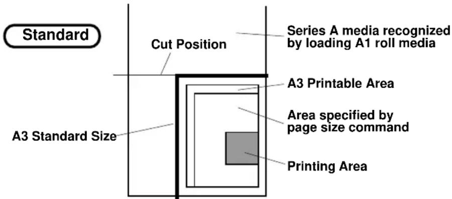 | |||
| Media cutSelects whether roll media will be cut at the end of printing. If off is selected, the data can be printed again on the same page.• Off:Cut offPrinting area for second copyRear margin of first copy and leading margin of second are missing* Printing area determined by layout• Auto: Roll media is cut automatically when printingAuto-cut ends.• Manual: Roll media is cut manually when printingManual cut ends. Use this for cutting media than can not be cut automatically (fireproof cloth or outdoors cloth). (See "Making a Manual Cut".) | Page 130 | ||
| CopySpecifies number of copies when the data is to be printed several times.• 1 to 99 | Page 131 | ||
| Ink DensitySet printing density.• Normal: Ordinary density printing• Micro: Printing density lighter than "Normal" | Page 132 | ||
| Distance AdjustmentEnter the length according to the data and the actual X-axis distance based on the actual printed document. If there is no setting, the length and width of the previously printed document is displayed. The distance adjustment is for adjusting to the user's scale, not for ensuring distance precision. | Page 133 | ||
Understanding the Functions
Function Settings / Centronics Settings / Network Settings
| Name of Function | Reference Page |
| * "Normal" and "Micro" are all valid if the resolution is set to pseudo-1440 dpi or 720 dpi but please note that if 360 dpi is set, the printing density will be "Normal" even when "Micro" is set.No: No distance adjustment is madeClear: To erase the current distance adjustment settingChange: To set a distance adjustmentConfirm: To confirm a distance adjustment |
Centronics Settings
| Name of Function | Reference Page |
| Mode | Page 136 |
| Sets the mode for the Centronics connection.• Centronics: Selects fixed one-way Centronics communication• BiCentronics: Selects Bitronics that allows two-way communication (supports compatible mode, nibble mode, ECP mode) | |
| Timing | Page 137 |
| Sets ACK timing for Centronics online communication• A-B: Selects ACK timing for the A-B busy method• B-A: Selects ACK timing for the B-A busy method |
Network Settings
| Name of Function | Reference Page |
| IP address | Page 138 |
| Sets up IP address for the network connection (Ethernet).Enter the IP address assigned by your network administratorAfter making the setting, turn the printer off momentarily and restart it.• 000.000.000.000 to 192.034.043.015 to 255.255.255.255 |
Utility Settings
| Name of Function | Reference Page |
| Error Display | Page 140 |
| Specifies whether the error LED will light and error details will be displayed in the liquid crystal display unit when a minor error has occurred.• On: The error LED will light and error details will be displayed in the liquid crystal display unit when a minor error has occurred• Off: No indication will be given of a minor error occurring, either by error LED or by the liquid crystal display unit | |
| Initial All | Page 141 |
| Restores the contents of all backed up settings to the values set when shipped by Mutoh.• OK: All backed up settings are restored to the factory settings• No: Factory settings are not restored | |
| Initial Command | Page 143 |
| Restores the backed up command settings to the values set when shipped by Mutoh.• OK: The backed up command settings are restored to the factory settings• No: Factory settings are not restored | |
| Initial Function | Page 145 |
| Restores the backed up function settings to the values set when shipped by Mutoh.• OK: The backed up function settings are restored to the factory settings• No: Factory settings are not restored | |
| Initial Centronics | Page 147 |
| Restores the backed up Centronics settings to the values set when shipped by Mutoh. | |
| • OK: The backed up Centronics settings are restored to the factory settings | |
| • No: Factory settings are not restored | |
| Initial Network | Page 149 |
| Restores the backed up Network settings to the values set when shipped by Mutoh. | |
| • OK: The backed up Network settings are restored to the factory settings | |
| • No: Factory settings are not restored | |
| Dump | Page 151 |
| Prints a dump for the serviceman to check online. | |
| • Start-End: Prints a dump from start to end | |
| • All: Prints a dump for all data | |
| Wash | Page 153 |
| Withdraws the filled ink and cleans the interior of the head. After cleaning, the head must be filled with ink for printing. | |
| • Yes: Head is cleaned. | |
| • No: Head is not cleaned. | |
| Clean | Page 156 |
| Withdraws the filled ink and cleans the interior of the head. After cleaning, the head will be filled automatically. Your printer is ready for printing. | |
| • Normal : Starts a NORMAL cleaning. | |
| • Powerful: Starts a POWERFUL cleaning. | |
| Fill | Page 157 |
| Starts a Ink Fill sequence (ink from cassettes to heads) Yes/No | |
| Ink Change | Page 159 |
| Starts Ink Change procedure (No / Yes) |
How to Set Parameters
This section explains how to set parameters for all types of menu.
Command and functions settings:
| Command | PAGE 113 |
| Plot Area | PAGE 114 |
| Position | PAGE 115 |
| Terminator | PAGE 116 |
| Resolution | PAGE 117 |
| Online Timer | PAGE 118 |
| Overwrite | PAGE 120 |
| Origin Reset | PAGE 121 |
| Ink Dry Time | PAGE 122 |
| Halftone | PAGE 124 |
| CMY -> Black | PAGE 125 |
| Scale | PAGE 126 |
| Mirror | PAGE 127 |
| Direction | PAGE 128 |
| Cut Position | PAGE 129 |
| Media Cut | PAGE 130 |
| Copy | PAGE 131 |
| Ink Density | PAGE 132 |
| Distance Adjustment | PAGE 133 |
Centronics Settings:
| Mode | PAGE 136 |
| Timing | PAGE 137 |
Network Setting:
| IP Address | PAGE 138 |
Utility Settings:
| Error Display | PAGE 140 |
Utility Settings: Initial
| All | PAGE 141 |
| Command | PAGE 143 |
| Function | PAGE 145 |
| Centronics | PAGE 147 |
| Network | PAGE 149 |
Utility Settings:
| Dump | PAGE 151 |
| Wash | PAGE 153 |
| Clean | PAGE 156 |
| Fill | PAGE 157 |
| Ink Change | PAGE 159 |
Command Settings: Command
P I o t O K
* Menu * Command >
* Menu * Command >
Command : MHGL, GL2
Command : RTL -PASS
Plot Area: Norma
* Menu * Command >
P I o t O K
Step 1
If a menu is to be specified, press the [MENU] key.
Step 2
The key contents change to the purple section on the outside of the control panel.
Bring up the "Command" menu by pressing the [Menu Up] key or [Menu Down] key.
Step 3
Display a Command item by pressing the [Menu Up] key or [Menu Down] key.
Step 4
Specify "MHGL, GL2", "MH-GL2" or "RTL-PASS" by pressing the [VALUE+] or [VALUE -] key.
Step 5
Press the [ENTER] key to confirm "Command" setting and shift to the next item to be set.
Step 6
If no other items are to be changed, press the [Back] key.
Step 7
Do not press any other keys for 3 minutes or press [Back] key again.
Step 8
The permanent display is restored.
Command Settings: Plot Area
P I o t O K
* Menu * Command >
* Menu * Command >
Command : MHGL , GL2
Plot Area: Normal
PlotArea: Expand
Pos it i on :
* Menu * Command >
P I o t O K
Step 1
If a menu is to be specified, press the [MENU] key.
Step 2
The key contents change to the purple section on the outside of the control panel.
Bring up the "Command" menu by pressing the [Menu Up] key or [Menu Down] key.
Step 3
Press the [ENTER] key to confirm the "Command" menu and shift to the next level.
Step 4
Bring up the "Plot Area" item by pressing the [Menu Up] key or [Menu Down] key.
Step 5
Press the [VALUE +] or [VALUE -] key to select "Normal" or "Expand".
Step 6
Press the [ENTER] key to confirm "Plot Area" and shift to the next item to be set.
Step 7
If no other items are to be changed, press the [Back] key.
Step 8
Do not press any other keys for 3 minutes or press [Back] key again.
Step 9
The permanent display is restored.
Command Settings: Position
P I o t O K
* Menu * Command >
* Menu * Command >
Command: MHGL, GL2
Position :
Position :
Terminat : Specia
* Menu * Command >
P I o t O K
Step 1
If a menu is to be specified, press the [MENU] key.
Step 2
The key contents change to the purple section on the outside of the control panel.
Bring up the "Command" menu by pressing the [Menu Up] key or [Menu Down] key.
Step 3
Press the [ENTER] key to confirm the "Command" menu and shift to the next level.
Step 4
Bring up the "Position" item by pressing the [Menu Up] key or [Menu Down] key.
Step 5
Press the [VALUE +] or [VALUE -] key to select "P1" or "LL (Hardclip lower left)" or "Full".
Step 6
Press the [ENTER] key to confirm "Position" and shift to the next item to be set.
Step 7
If no other items are to be changed, press the [Back] key.
Step 8
Do not press any other keys for 3 minutes or press [Back] key again.
Step 9
The permanent display is restored.
Command Settings:Terminator
P I o t O K
* Menu * Command >
* Menu * Command >
Command : MHGL, GL2
Terminat: Special
Terminat: Normal
Resolut.: 360dp
* Menu * Command >
P I o t O K
Step 1
If a menu is to be specified, press the [MENU] key.
Step 2
The key contents change to the purple section on the outside of the control panel.
Bring up the "Command" menu by pressing the [Menu Up] key or [Menu Down] key.
Step 3
Press the [ENTER] key to confirm the "Command" menu and shift to the next level.
Step 4
Bring up the "Terminat" item by pressing the [Menu Up] key or [Menu Down] key.
Step 5
Press the [VALUE +] or [VALUE -] key to select "Special" or "Normal".
Step 6
Press the [ENTER] key to confirm "Terminat" and shift to the next item to be set.
Step 7
If no other items are to be changed, press the [Back] key.
Step 8
Do not press any other keys for 3 minutes or press [Back] key again.
Step 9
The permanent display is restored.
Command Settings: Resolution
P I o t O K
* Menu * Command >
* Menu * Command >
Command : MHGL, GL2
R esolut.: 360dp i
R esolut.: 720dp i
OnlineTimer: 30s
* Menu * Command >
P I o t O K
Step 1
If a menu is to be specified, press the [MENU] key.
Step 2
The key contents change to the purple section on the outside of the control panel.
Bring up the "Command" menu by pressing the [Menu Up] key or [Menu Down] key.
Step 3
Press the [ENTER] key to confirm the "Command" menu and shift to the next level.
Step 4
Bring up the "Resolut." item by pressing the [Menu Up] key or [Menu Down] key.
Step 5
Press the [VALUE +] or [VALUE -] key to select "360dpi", "720dpi" or "300dpi".
Step 6
Press the [ENTER] key to confirm "Resolution" and shift to the next item to be set.
Step 7
If no other items are to be changed, press the [Back] key.
Step 8
Do not press any other keys for 3 minutes or press [Back] key again.
Step 9
The permanent display is restored.
Command Settings: Online Timer
P I o t O K
* Menu * Command >
* Menu * Command >
Command : MHGL , GL2
On LineTimer: 30s
OnlineTimer : 270s
Overwrite: Last
* Menu * Command >
Step 1
If a menu is to be specified, press the [MENU] key.
Step 2
The key contents change to the purple section on the outside of the control panel.
Bring up the "Command" menu by pressing the [Menu Up] key or [Menu Down] key.
Step 3
Press the [ENTER] key to confirm the "Command" menu and shift to the next level.
Step 4
Bring up the "Online Timer" item by pressing the [Menu Up] key or [Menu Down] key.
Step 5
Press the [VALUE +] or [VALUE -] key to select "Off", "10s", "10s", "20s", "30s", "40s", "50s", "60s", "90s", "120s", "150s", "180s", "210s", "240s", "270s" or "800s".
Step 6
Press the [ENTER] key to confirm "Online Timer" and shift to the next item to be set.
Step 7
If no other items are to be changed, press the [Back] key.
Step 8
Do not press any other keys for 3 minutes or press [Back] key again.
P I o t O K
Step 9
The permanent display is restored.
Command Settings: Overwrite
P I o t O K
* Menu * Command >
* Menu * Command >
Command : MHGL , GL2
Overwrite: Last
Overwrite: Mix
Command : MHGL, GL2
* Menu * Command >
P I o t O K
Step 1
If a menu is to be specified, press the [MENU] key.
Step 2
The key contents change to the purple section on the outside of the control panel.
Bring up the "Command" menu by pressing the [Menu Up] key or [Menu Down] key.
Step 3
Press the [ENTER] key to confirm the "Command" menu and shift to the next level
Step 4
Bring up the "Overwrite" item by pressing the [Menu Up] key or [Menu Down] key.
Step 5
Press the [VALUE +] or [VALUE -] key to select "Last" or "Mix".
Step 6
Press the [ENTER] key to confirm "Overwrite" and shift to the next item to be set.
Step 7
If no other items are to be changed, press the [Back] key.
Step 8
Do not press any other keys for 3 minutes or press [Back] key again.
Step 9
The permanent display is restored.
Command Settings: Origin Reset
P I o t O K
* Menu * Command >
* Menu * Command >
OriginReset : No
Origin Reset: Yes
Origin : Init
Origin : New >
Offset : 0
* Menu * Command >
P I o t O K
Step 1
If a menu is to be specified, press the [MENU] key.
Step 2
The key contents change to the purple section on the outside of the control panel.
Bring up the "Command" menu by pressing the [Menu Up] key or [Menu Down] key.
Step 3
Press the [ENTER] key to confirm the "Command" menu and shift to the next level
Step 4
Bring up the "OriginReset" item by pressing the [Menu Up] key or [Menu Down] key.
Step 5
Press the [VALUE +] or [VALUE -] key to select "Yes" or "No".
Step 6
Press the [VALUE +] or [VALUE -] key to select "new origin" or "initialisation". To select a new origin select "new>" and press the [ENTER] key to confirm.
Step 7
Set a new origin (0 to media width minus 20 mm) and pressthe [ENTER] key to confirm.
Step 8
Do not press any other keys for 3 minutes or press [Back] key again.
Step 9
The permanent display is restored.
Function Settings:Ink DryTime
P I o t O K
* Menu * Command >
* Menu * Function >
In k Dry Time: 30 s
In k Dry Time: 30 s
In k Dry Time: 60 s
Ha l ft tone: Speed
Step 1
If a menu is to be specified, press the [MENU] key.
Step 2
The key contents change to the purple section on the outside of the control panel.
Bring up the "Function" menu by pressing the [Menu Up] key or [Menu Down] key.
Step 3
Press the [ENTER] key to confirm the "Function" menu and shift to the next level.
Step 4
Bring up the "Ink Dry Time" item by pressing the [Menu Up] key or [Menu Down] key.
Step 5
Press the [VALUE +] or [VALUE -] key to select "0s", "5s", "10s", "20s", "30s", "40s", "50s", "60s", "90s", "120s", "150s", "180s", "210s", "240s", "270s" or "300s", "6M", "7M", "8M", "9M", "10M", "15M", "20M", "25M", "30M", "35M", "40M", "45M", "50M", "55M", or "60M"
Step 6
Press the [ENTER] key to confirm "Ink Dry Time" and shift to the next item to be set.
Step 7
If no other items are to be changed, press the [Back] key.
* Menu * Function >
P I o t O K
Step 8
Do not press any other keys for 3 minutes or press [Back] key again.
Step 9
The permanent display is restored.
Function Settings: Halftone
P I o t O K
* Menu * Command >
* Menu * Function >
In k Dry Time: 30 s
Halftone: Speed
Ha l f tone: Quality
CMY - >BLACK No
* Menu * Function >
P I o t O K
Step 1
If a menu is to be specified, press the [MENU] key.
Step 2
The key contents change to the purple section on the outside of the control panel.
Bring up the "Function" menu by pressing the [Menu Up] key or [Menu Down] key.
Step 3
Press the [ENTER] key to confirm the "Function" menu and shift to the next level.
Step 4
Bring up the "Halftone" item by pressing the [Menu Up] key or [Menu Down] key.
Step 5
Press the [VALUE +] or [VALUE -] key to set halftone to "Speed" diffusion, "Quality" diffusion or "Thin" diffusion.
Step 6
Press the [ENTER] key to confirm "Halftone" and shift to the next item to be set.
Step 7
If no other items are to be changed, press the [Back] key.
Step 8
Do not press any other keys for 3 minutes or press [Back] key again.
Step 9
The permanent display is restored.
Function Settings: CMY-> Black
P I o t O K
* Menu * Command >
* Menu * Function >
In k Dry Time: 30 s
CMY -> BLACK No
CMY -> BLACK Yes
Scale: 100%
* Menu * Function >
P I o t O K
Step 1
If a menu is to be specified, press the [MENU] key.
Step 2
The key contents change to the purple section on the outside of the control panel.
Bring up the "Function" menu by pressing the [Menu Up] key or [Menu Down] key.
Step 3
Press the [ENTER] key to confirm the "Function" menu and shift to the next level.
Step 4
Bring up the "CMY -> BLACK" item by pressing the [Menu Up] key or [Menu Down] key.
Step 5
Press the [VALUE +] or [VALUE -] key to set "No" or "Yes".
Step 6
Press the [ENTER] key to confirm "CMY -> BLACK" and shift to the next item to be set.
Step 7
If no other items are to be changed, press the [Back] key.
Step 8
Do not press any other keys for 3 minutes or press [Back] key again.
Step 9
The permanent display is restored.
Function Settings: Scale
P I o t O K
* Menu * Command >
* Menu * Function >
In k Dry Time: 30 s
Scale: 100%
Scale: 120%
Mirror: Off
* Menu * Function >
P I o t O K
Step 1
If a menu is to be specified, press the [MENU] key.
Step 2
The key contents change to the purple section on the outside of the control panel.
Bring up the "Function" menu by pressing the [Menu Up] key or [Menu Down] key.
Step 3
Press the [ENTER] key to confirm the "Function" menu and shift to the next level.
Step 4
Bring up the "Scale" item by pressing the [Menu Up] key or [Menu Down] key.
Step 5
Press the [VALUE +] or [VALUE -] key to set scale magnification between "25%" and "400%".
Step 6
Press the [ENTER] key to confirm "Scale" and shift to the next item to be set.
Step 7
If no other items are to be changed, press the [Back] key.
Step 8
Do not press any other keys for 3 minutes or press [Back] again.
Step 9
The permanent display is restored.
Function Settings: Mirror
P I o t O K
* Menu * Command >
* Menu * Function >
In k Dry Time: 30 s
Mirror: Off
Mirror: Y On
Direct.: Command
* Menu * Function >
P I o t O K
Step 1
If a menu is to be specified, press the [MENU] key.
Step 2
The key contents change to the purple section on the outside of the control panel.
Bring up the "Function" menu by pressing the [Menu Up] key or [Menu Down] key.
Step 3
Press the [ENTER] key to confirm the "Function" menu and shift to the next level.
Step 4
Bring up the "Mirror" item by pressing the [Menu Up] key or [Menu Down] key.
Step 5
Press the [VALUE+] or [VALUE-] key to set mirror to "Off" or "Y On".
Step 6
Press the [ENTER] key to confirm "Mirror" for the applicable print and shift to the next item to be set.
Step 7
If no other items are to be changed, press the [Back] key.
Step 8
Do not press any other keys for 3 minutes or press [Back] key again.
Step 9
The permanent display is restored.
Function Settings: Direction
P I o t O K
* Menu * Command >
* Menu * Function >
In k Dry Time: 30 s
Direct.: Command
Direct.: MAX-MIN
CutPos.: Data
* Menu * Function >
P I o t O K
Step 1
If a menu is to be specified, press the [MENU] key.
Step 2
The key contents change to the purple section on the outside of the control panel.
Bring up the "Function" menu by pressing the [Menu Up] key or [Menu Down] key.
Step 3
Press the [ENTER] key to confirm the "Function" menu and shift to the next level.
Step 4
Bring up the "Direct." item by pressing the [Menu Up] key or [Menu Down] key.
Step 5
Press the [VALUE +] or [VALUE -] key to specify "Command" or "MAX-MIN".
Step 6
Press the [ENTER] key to confirm "Direction" and shift to the next item to be set.
Step 7
If no other items are to be changed, press the [Back] key.
Step 8
Do not press any other keys for 3 minutes or press [Back] key again.
Step 9
The permanent display is restored.
Function Settings: Cut Position
P I o t O K
* Menu * Command >
* Menu * Function >
In k Dry Time: 30 s
CutPos.: Data
CutPos.:Standard
Media Cut: Auto
* Menu * Function >
P I o t O K
Step 1
If a menu is to be specified, press the [MENU] key.
Step 2
The key contents change to the purple section on the outside of the control panel.
Bring up the "Function" menu by pressing the [Menu Up] key or [Menu Down] key.
Step 3
Press the [ENTER] key to confirm the "Function" menu and shift to the next level.
Step 4
Bring up the "Cut Pos." item by pressing the [Menu Up] key or [Menu Down] key.
Step 5
Press the [VALUE +] or [VALUE -] key to specify "Data" or "Standard".
Step 6
Press the [ENTER] key to confirm "Cut Position" and shift to the next item to be set.
Step 7
If no other items are to be changed, press the [Back] key.
Step 8
Do not press any other keys for 3 minutes or press [Back] key again.
Step 9
The permanent display is restored.
Function Settings: Media Cut
P I o t O K
* Menu * Command >
* Menu * Function >
In k Dry Time: 30 s
Media Cut: Auto
MediaCut: Manual
Copy : 1
* Menu * Function >
P I o t O K
Step 1
If a menu is to be specified, press the [MENU] key.
Step 2
The key contents change to the purple section on the outside of the control panel.
Bring up the "Function" menu by pressing the [Menu Up] key or [Menu Down] key.
Step 3
Press the [ENTER] key to confirm the "Function" menu and shift to the next level.
Step 4
Bring up the "Media cut" item by pressing the [Menu Up] key or [Menu Down] key.
Step 5
Press the [VALUE +] or [VALUE -] key to specify "Off", "Auto" cut or "Manual" cut.
Step 6
Press the [ENTER] key to confirm "Media Cut" and shift to the next item to be set.
Step 7
If no other items are to be changed, press the [Back] key.
Step 8
Do not press any other keys for 3 minutes or press [Back] key again.
Step 9
The permanent display is restored.
Function Settings: Copy
P I o t O K
* Menu * Command >
* Menu * Function >
In k Dry Time: 30 s
C o p y : 1
C o p y : 15
Ink Density Norma
* Menu * Function >
P I o t O K
Step 1
If a menu is to be specified, press the [MENU] key.
Step 2
The key contents change to the purple section on the outside of the control panel.
Bring up the "Function" menu by pressing the [Menu Up] key or [Menu Down] key.
Step 3
Press the [ENTER] key to confirm the "Function" menu and shift to the next level.
Step 4
Bring up the "Copy" item by pressing the [Menu Up] key or [Menu Down] key.
Step 5
Press the [VALUE +] or [VALUE -] key to set the number of copies between "1" and "99".
Step 6
Press the [ENTER] key to confirm the number of copies of the applicable print and shift to the next item to be set.
Step 7
If no other items are to be changed, press the [Back] key.
Step 8
Do not press any other keys for 3 minutes or press [Back] key again.
Step 9
The permanent display is restored.
Function Settings: Ink Density
P I o t O K
* Menu * Command >
* Menu * Function >
In k Dry Time: 30 s
InkDensity Norma
Ink Density: Micro
D i s t. A d j : N o
* Menu * Function >
P I o t O K
Step 1
If a menu is to be specified, press the [MENU] key.
Step 2
The key contents change to the purple section on the outside of the control panel.
Bring up the "Function" menu by pressing the [Menu Up] key or [Menu Down] key.
Step 3
Press the [ENTER] key to confirm the "Function" menu and shift to the next level
Step 4
Bring up the "Ink Density" item by pressing the [Menu Up] key or [Menu Down] key.
Step 5
Press the [VALUE +] or [VALUE -] key to set the density to "Normal" or "Micro".
Step 6
Press the [ENTER] key to confirm "Ink Density" shift to the next item to be set.
Step 7
If no other items are to be changed, press the [Back] key.
Step 8
Do not press any other keys for 3 minutes or press [Back] key again.
Step 9
The permanent display is restored.
FunctionSettings:DistanceAdjustment
P I o t O K
* Menu * Command >
* Menu * Function >
In k Dry Time: 30 s
D i s t . A d j : N o
Dist. Adj: Change
Data X: 00841.00
Step 1
If a menu is to be specified, press the [MENU] key.
Step 2
The key contents change to the purple section on the outside of the control panel.
Bring up the "Function" menu by pressing the [Menu Up] key or [Menu Down] key.
Step 3
Press the [ENTER] key to confirm the "Function" menu and shift to the next level
Step 4
Bring up the "Dist. Adj." item by pressing the [Menu Up] key or [Menu Down] key.
Step 5
Press the [VALUE +] or [VALUE -] key to set "Change".
Step 6
Press the [ENTER] key to confirm the "Distance Adjustment" submenu and shift to the next level.
Step 7
Press the [Menu Up] key or [Menu Down] key to shift to the panel for changing "Distance Adjustment X-axis Data". the value that is displayed becomes the currently set value. If no setting is to be made, it will be the width of the previously printed document. An underline shows the digit to be altered.
Data X: 00841.00
Data X: 00801.00
Data X: 00801.00
Data X: 00800.00
Real X: 00800.00
Real X: 00800.00
Real X: 00800.20
Real X: 00800.20
Step 8
Set the value of the digit to be altered by pressing the [VALUE+] or [VALUE-] key.
Step 9
Continue by pressing the [Menu Up] key or [Menu Down] key to shift to another digit to be altered.
Step 9
Set the value of the digit to be altered by pressing the [VALUE+] or [VALUE-] key.
Step 10
Press [ENTER] to set "Distance Adjustment X-axis Data Value".
Step 11
Specify the X measurement from the printed document in order to display the "Distance Adjustment X-axis Data Value".
Press the [Menu Up] key or [Menu Down] key to shift to the "X-axis Data" digit that is to be altered.
Step 12
Set the value of the digit in the measured value by pressing the [VALUE +] or [VALUE -] key.
Step 13
Continue by pressing the [Menu Up] key or [Menu Down] key to shift to another digit to be altered.
Step 14
Set the value of the digit in the measured value by pressing the [VALUE +] or [VALUE -] key.
Real X: 00800.25
Dist .Adj : Change
* Menu * Function >
P I o t O K
Step 15
Press [ENTER] key to set "Distance Adjustment X-axis Measured Value".
Step 16
Distance Correction item is restored. If no other items are to be changed, press the [Back] key.
Step 17
Do not press any other keys for 3 minutes or press [Back] key again
Step 18
The permanent display is restored
Centronics Settings: Mode
P I o t O K
* Menu * Command >
* Menu * Centro >
Mode : Centro
Mode : Centro
Mode: Bi Centro
Timing: A-B
* Menu * Centro >
P I o t O K
Step 1
If a menu is to be specified, press the [MENU] key.
Step 2
The key contents change to the purple section on the outside of the control panel.
Bring up the "Centronics" menu by pressing the [Menu Up] key or [Menu Down] key.
Step 3
Press the [ENTER] key to confirm the "Centronics" menu and shift to the next level.
Step 4
Bring up the "Mode" item by pressing the [Menu Up] key or [Menu Down] key.
Step 5
Press the [VALUE +] or [VALUE -] key to switch to "Centro" or "Bi Centro".
Step 6
Press the [ENTER] key to confirm "Mode" and shift to the next item to be set.
Step 7
If no other items are to be changed, press the [Back] key.
Step 8
Do not press any other keys for 3 minutes or press [Back] key again.
Step 9
The permanent display is restored.
Centronics Settings: Timing
P I o t O K
* Menu * Command >
* Menu * Centro >
Mode : Centro
Timing: A-B
Timing: B-A
Mode : Centro
* Menu * Centro >
P I o t O K
Step 1
If a menu is to be specified, press the [MENU] key.
Step 2
The key contents change to the purple section on the outside of the control panel.
Bring up the "Centronics" menu by pressing the [Menu Up] key or [Menu Down] key.
Step 3
Press the [ENTER] key to confirm the "Centronics" menu and shift to the next level.
Step 4
Bring up the "Timing" item by pressing the [Menu Up] key or [Menu Down] key.
Step 5
Press the [VALUE +] or [VALUE -] key to switch to "A-B" or "B-A".
Step 6
Press the [ENTER] key to confirm "Timing" and shift to the next item to be set.
Step 7
If no other items are to be changed, press the [Back] key.
Step 8
Do not press any other keys for 3 minutes or press [Back] key again.
Step 9
The permanent display is restored.
Network Setting: IP Address
P I o t O K
* Menu * Command >
* Menu * Network >
->192.034.043.015
->1 9 2 . 0 3 4 . 0 4 3 . 0 1 5
1 9 2 -> 0 3 4 . 0 4 3 . 0 1 5
1 9 2 -> 1 6 8 . 0 4 3 . 0 1 5
Step 1
If a menu is to be specified, press the [MENU] key.
Step 2
The key contents change to the purple section on the outside of the control panel.
Bring up the "Network" menu by pressing the [Menu Up] key or [Menu Down] key.
Step 3
Press the [ENTER] key to confirm the "Network" menu and shift to the next level.
Step 4
Press the [VALUE+] or [VALUE-] key to set the first part of the IP address to a number between "001" and "255". (The first part identifies the country and 192 is usually used in a LAN environment.
Step 5
Press the [ENTER] key to confirm the first address and shift to the second address.
Step 6
Press the [VALUE +] or [VALUE -] key to set the second part of the IP address to a number between "001" and "255".
Step 7
Press the [ENTER] key to confirm the second address and shift to the third address.
1 9 2 . 1 6 8 - > 0 4 3 . 0 1 5
1 9 2 . 1 6 8 - > 0 0 1 . 0 1 5
1 9 2 . 1 6 8 . 0 0 1 - > 0 1 5
192.168.001->007
- > 1 9 2 . 1 6 8 . 0 0 1 . 0 0 7
* Menu * Network >
P I o t O K
Step 8
Press the [VALUE +] or [VALUE -] key to set the third part of the IP address to a number between "001" and "255".
Step 9
Press the [ENTER] key to confirm the third address and shift to the fourth address.
Step 10
Press the [VALUE +] or [VALUE -] key to set the fourth part of the IP address to a number between "001" and "255".
Step 11
Press the [ENTER] key to confirm the fourth address and shift to the first address.
Step 12
Press the [Back] key.
Step 13
Do not press any other keys for 3 minutes or press [Back] key again.
Step 14
The permanent display is restored.
Utility Settings: Error Display
P I o t O K
* Menu * Command >
* Menu * Utility >
Error Display: Off
Error Display: Off
Error Display: On
I n i t i a l : N o
* Menu * Utility >
P I o t O K
Step 1
If a menu is to be specified, press the [MENU] key.
Step 2
The key contents change to the purple section on the outside of the control panel.
Bring up the "Utility" menu by pressing the [Menu Up] key or [Menu Down] key.
Step 3
Press the [ENTER] key to confirm the "Utility" menu and shift to the next level.
Step 4
Bring up the "Error Display" item by pressing the [Menu Up] key or [Menu Down] key.
Step 5
Press the [VALUE +] or [VALUE -] key to switch to "Off" or "On".
Step 6
Press the [ENTER] key to confirm "Error display" and shift to the next item to be set.
Step 7
If no other items are to be changed, press the [Back] key.
Step 8
Do not press any other keys for 3 minutes or press [Back] key again.
Step 9
The permanent display is restored.
Utility Settings: Initial: All
P I o t O K
* Menu * Command >
* Menu * Utility >
Error Display: Off
Initial: No
Initial: Yes>
Initial All: No
Initial All: No
Initial All: OK
Step 1
If a menu is to be specified, press the [MENU] key.
Step 2
The key contents change to the purple section on the outside of the control panel.
Bring up the "Utility" menu by pressing the [Menu Up] key or [Menu Down] key.
Step 3
Press the [ENTER] key to confirm the "Utility" menu and shift to the next level.
Step 4
Bring up the "Initial" item by pressing the [Menu Up] key or [Menu Down] key.
Step 5
Press the [VALUE +] or [VALUE -] key to specify "Yes".
Step 6
Press the [ENTER] key to confirm "Initial" and shift to "Initial All".
Step 7
Bring up the "Initial All" item by pressing the [Menu Up] key or [Menu Down] key.
Step 8
Press the [VALUE +] or [VALUE -] key to specify "OK".
Step 9
Press the [ENTER] key to confirm "Initial All" and shift to to the next item to be set.
Initial Command N
0
Initial: No
-
* Menu * Utility >
-
Plot OK
-
Step 10
If no other items are to be changed, press the [Back] key.
Step 11
If no other items are to be changed, press the [Back] key.
Step 12
Do not press any other keys for 3 minutes or press [Back] key again.
Step 13
The permanent display is restored.
Utility Settings: Initial: Command
P I o t O K
* Menu * Command >
* Menu * Utility >
Error Display: Off
Initial: No
Initial: Yes>
Initial All: No
InitialCommandNo
InitialCommandOK
Step 1
If a menu is to be specified, press the [MENU] key.
Step 2
The key contents change to the purple section on the outside of the control panel.
Bring up the "Utility" menu by pressing the [Menu Up] key or [Menu Down] key.
Step 3
Press the [ENTER] key to confirm the "Utility" menu and shift to the next level.
Step 4
Bring up the "Initial" item by pressing the [Menu Up] key or [Menu Down] key.
Step 5
Press the [VALUE +] or [VALUE -] key to specify "Yes".
Step 6
Press the [ENTER] key to confirm "Initial" and shift to "Initial All".
Step 7
Bring up the "Initial Command" item by pressing the [Menu Up] key or [Menu Down] key.
Step 8
Press the [VALUE +] or [VALUE -] key to specify "OK".
Step 9
Press the [ENTER] key to confirm "Initial Command" and shift to the next item to be set.
Initial Functi. No
Initial: No
* Menu * Utility >
P I o t O K
Step 10
If no other items are to be changed, press the [Back] key.
Step 11
If no other items are to be changed, press the [Back] key.
Step 12
Do not press any other keys for 3 minutes or press [Back] key again.
Step 13
The permanent display is restored.
Utility Settings: Initial: Function
P I o t O K
* Menu * Command >
* Menu * Utility >
Error Display: Off
Initial: No
Initial: Yes>
Initial All: No
Initial Function. No
I n i t i a l F u n c t i . O K
Step 1
If a menu is to be specified, press the [MENU] key.
Step 2
The key contents change to the purple section on the outside of the control panel.
Bring up the "Utility" menu by pressing the [Menu Up] key or [Menu Down] key.
Step 3
Press the [ENTER] key to confirm the "Utility" menu and shift to the next level.
Step 4
Bring up the "Initial" item by pressing the [Menu Up] key or [Menu Down] key.
Step 5
Press the [VALUE +] or [VALUE -] key to specify "Yes".
Step 6
Press the [ENTER] key to confirm "Initial" and shift to "Initial All".
Step 7
Bring up the "Initial Functi." item by pressing the [Menu Up] key or [Menu Down] key.
Step 8
Press the [VALUE +] or [VALUE -] key to specify "OK".
Step 9
Press the [ENTER] key to confirm "Initial Function" and shift to the next item to be set.
Initial Centro: No
Initial: No
* Menu * Utility >
P I o t O K
Step 10
If no other items are to be changed, press the [Back] key.
Step 11
If no other items are to be changed, press the [Back] key.
Step 12
Do not press any other keys for 3 minutes or press [Back] key again.
Step 13
The permanent display is restored.
UtilitySettings: Initial: Centronics
P I o t O K
* Menu * Command >
* Menu * Utility >
Error Display: Off
Initial: No
Initial: Yes>
Initial All: No
Initial Centro: No
Initial Centro: OK
Step 1
If a menu is to be specified, press the [MENU] key.
Step 2
The key contents change to the purple section on the outside of the control panel.
Bring up the "Utility" menu by pressing the [Menu Up] key or [Menu Down] key.
Step 3
Press the [ENTER] key to confirm the "Utility" menu and shift to the next level.
Step 4
Bring up the "Initial" item by pressing the [Menu Up] key or [Menu Down] key.
Step 5
Press the [VALUE +] or [VALUE -] key to specify "Yes".
Step 6
Press the [ENTER] key to confirm "Initial" and shift to "Initial All".
Step 7
Bring up the "Initial Centro" item by pressing the [Menu Up] key or [Menu Down] key.
Step 8
Press the [VALUE +] or [VALUE -] key to specify "OK".
Step 9
Press the [ENTER] key to confirm "Initial Centronics" and shift to the next item to be set.


text_image
I n i t i a l: N o

text_image
P I o t O KStep 10
If no other items are to be changed, press the [Back] key.
Step 11
If no other items are to be changed, press the [Back] key.
Step 12
Do not press any other keys for 3 minutes or press [Back] key again.
Step 13
The permanent display is restored.
Utility Settings: Initial: Network
P I o t O K
* Menu * Command >
* Menu * Utility >
Error Display: Off
Initial: No
Initial: Yes>
Initial All: No
Initial Network No
Initial NetworkOK
Step 1
If a menu is to be specified, press the [MENU] key.
Step 2
The key contents change to the purple section on the outside of the control panel.
Bring up the "Utility" menu by pressing the [Menu Up] key or [Menu Down] key.
Step 3
Press the [ENTER] key to confirm the "Utility" menu and shift to the next level.
Step 4
Bring up the "Initial" item by pressing the [Menu Up] key or [Menu Down] key.
Step 5
Press the [VALUE +] or [VALUE -] key to specify "Yes".
Step 6
Press the [ENTER] key to confirm "Initial" and shift to "Initial All".
Step 7
Bring up the "Initial Network" item by pressing the [Menu Up] key or [Menu Down] key.
Step 8
Press the [VALUE +] or [VALUE -] key to specify"OK".
Step 9
Press the [ENTER] key to confirm "Initial Network" and shift to the next item to be set.

text_image
I n i t i a l A l l : N o
text_image
I n i t i a l: N o
text_image
* Menu * Utility >
text_image
P I o t OKStep 10
If no other items are to be changed, press the [Back] key.
Step 11
If no other items are to be changed, press the [Back] key.
Step 12
Do not press any other keys for 3 minutes or press [Back] key again.
Step 13
The permanent display is restored.
Utility Settings: Dump
P I o t O K
* Menu * Command >
* Menu * Utility >
Error Display: Off
Dump: Start / End
Dump : A11
* * Dump Mode * *
* * Dump Mode * *
* Menu * Utility >
Step 1
If a menu is to be specified, press the [MENU] key.
Step 2
The key contents change to the purple section on the outside of the control panel.
Bring up the "Utility" menu by pressing the [Menu Up] key or [Menu Down] key.
Step 3
Press the [ENTER] key to confirm the "Utility" menu and shift to the next level.
Step 4
Bring up the "Dump" item by pressing the [Menu Up] key or [Menu Down] key.
Step 5
Select "Start/End" or "All" by pressing the [Menu Up] key or [Menu Down] key.
Step 6
Press the [ENTER] key to confirm Dump mode.
Step 7
Send printing data from the host computer. print with Dump Mode.
Step 8
To terminate Dump Mode, press the [CANCEL] key.
Step 9
Do not press any other keys for 3 minutes or press [Back] key again.
P I o t O K
Step 10
The permanent display is restored.
Utility Settings: Wash
P I o t O K
* Menu * Command >
* Menu * Utility >
Error Display: Off
Wash: No
Wash: Yes
Change Waste Ink
ChangeTank? No
ChangeTank? Yes
Step 1
If a menu is to be specified, press the [MENU] key.
Step 2
The key contents change to the purple section on the outside of the control panel.
Bring up the "Utility" menu by pressing the [Menu Up] key or [Menu Down] key.
Step 3
Press the [ENTER] key to confirm the "Utility" menu and shift to the next level.
Step 4
Bring up the "Wash" item by pressing the [Menu Up] key or [Menu Down] key.
Step 5
Select "Yes" by pressing the [Menu Up] key or [Menu Down] key.
Step 6
Press the [ENTER] key to confirm "Wash".
Step 7
Remove the currently installed waste box and insert a new waste liquid box from the cleaning set.
Step 8
Select "Yes" by pressing the [Menu Up] key or [Menu Down] key.
Step 9
Press the [ENTER] key to confirm waste box replaced.
Remove Cartridge
Set Wash Cart
Head Wash
Remove Wash Cart
Head Wash
Change Waste Ink
ChangeTank? No
ChangeTank? Yes
[65YMCK]NoCharge
Step 10
Remove the currently installed ink cartridges.
Step 11
Insert wash cartridges.
Step 12
Cleaning begins when wash cartridges are installed. Cleaning time is about 25 minutes.
Step 13
Remove the cleaning cartridges when head wash finishes and "Remove Wash Cart" appears.
Step 14
When the wash cartridges are removed, the operation to discharge cleaning liquid remaining inside the printer begins.
Step 15
Remove the waste box that was used for cleaning and insert another new waste liquid box from the cleaning set.
Step 16
Select "Yes" by pressing the [Menu Up] key or [Menu Down] key.
Step 17
Press the [ENTER] key to confirm waste box replaced.
Step 18
Ink filling begins automatically when ink cartridges are installed.
P I o t O K
Step 19
When ink filling is finished, the permanent display is restored.
Utility Settings: Clean
P I o t O K
* Menu * Command >
* Menu * Utility >
Clean: Normal
Clean: Powerful
Clean: Powerful
Error Display: Off
* Menu * Utility >
P I o t O K
Step 1
If a menu is to be specified, press the [MENU] key.
Step 2
The key contents change to the purple section on the outside of the control panel.
Bring up the "Utility" menu by pressing the [Menu Up] key or [Menu Down] key.
Step 3
Press the [ENTER] key to confirm the "Utility" menu and shift to the next level.
Step 4
Bring up the "Clean" item by pressing either [Menu Up] key or [Menu Down] key.
Step 5
Press the [VALUE +] or [VALUE -] key to select to "Normal" or "Powerful".
Step 6
Press the [ENTER] key to confirm the cleaning cycle.
Step 7
If no other items are to be changed, press the [Back] key.
Step 8
Do not press any other keys for 3 minutes or press [Back] key again.
Step 9
The permanent display is restored.
Utility Settings: Fill

Caution:
- Before starting the "fill" procedure, please be sure to empty the waste ink bottles. The waste ink bottles must be empty.
P I o t O K
* Menu * Command >
* Menu * Utility >
Error Display: Off
Fill: No
Fill: Yes
Step 1
If a menu is to be specified, press the [MENU] key.
Step 2
The key contents change to the purple section on the outside of the control panel.
Bring up the "Utility" menu by pressing the [Menu Up] key or [Menu Down] key.
Step 3
Press the [ENTER] key to confirm the "Utility" menu and shift to the next level.
Step 4
Bring up the "Fill" item by pressing either [Menu Up] key or [Menu Down] key.
Step 5
Press the [VALUE +] or [VALUE -] key to select to "No" or "Yes".
Step 6
Press the [ENTER] key to confirm the cleaning cycle.
| Ink Refill | 4 M |
| Ink Refill | 3 M |
| Ink Refill | 2 M |
| Ink Refill | 1 M |
| Ink Refill | 0 M |
Plot OK
Step 7
The ink refill procedure is executed. The display will show the following messages :
Step 8
The permanent display is restored.
Utility Settings: Ink Change
Use the INK CHANGE procedure to switch from DYE ink to PIGMENTED ink or from PIGMENTED ink to DYE ink. Use the INK CHANGE procedure to switch from Dye or Pigmented ink to ECO-SOLVENT INK.

CAUTION
- After using Eco-Solventink it is not possible to change to other type of ink (pigmented and dye inks). Before installing and changing to Eco-Solvent ink, the machine needs to go through a cleaning cycle with special Eco-Solvent transition liquid.
P I o t OK
* Menu * Command >
* Menu * Utility >
Ink Change: No
InkChange: Yes
Change Waste Ink
Step 1
If a menu is to be specified, press the [MENU] key.
Step 2
The key contents change to the purple section on the outside of the control panel.
Bring up the "Utility" menu by pressing the [Menu Up] key or [Menu Down] key.
Step 3
Press the [ENTER] key to confirm the "Utility" menu and shift to the next level.
Step 4
Bring up the "nkChange" item by pressing either [Menu Up] key or [Menu Down] key.
Step 5
Press the [VALUE +] or [VALUE -] key to select to "Yes" and press ENTER.
Step 6
Empty the waste ink bottles.
Change Tank? Yes
Confirm Change Yes
Remove Cart
Set Wash Cart
HEAD WASH
Remove Wash Cart
Head Wash
Change Waste ink
ChangeTank? Yes
ConfirmChange Yes
Step 7
Press the [VALUE +] or [VALUE -] key to select "YES" and press ENTER.
Step 8
Press the [VALUE +] or [VALUE -] key to select "YES" and press ENTER.
Step 9
Remove ink cartridges from the slot.
Step 10
Insert the cleaning cartridge to the ink cartridge slots. Use the special Eco-Solvent Transition Liquid when changing to Eco-Solvent ink. The head wash starts when the cleaning cartridge is inserted.
Step 11
Remove the cleaning cartridge from the slot.
Step 12
The rest of the cleaning fluid in the printer unit is discharged when the cleaning cartridge is removed.
Step 13
Empty the waste ink bottle from the printer unit.
Step 14
Press the [VALUE +] or [VALUE -] key to select "YES" and press ENTER.
Step 15
Press the [VALUE +] or [VALUE -] key to select "YES" and press ENTER.
[YMCK] Discharged
Step 16
If the cassettes that have been removed are DYE ink cassettes, now insert Pigmented ink cassettes or Eco-Solvent ink cassettes. If the cassettes that have been removed are PIGMENTED ink cassettes, now insert Dye ink cassettes or Eco-Solvent ink cassettes.

CAUTION
- After using Eco-Solvent ink it is not possible to change to other type of ink (Pigmented and Dye inks).
| Ink Refill | 4 M |
| Ink Refill | 3 M |
| Ink Refill | 2 M |
| Ink Refill | 1 M |
| Ink Refill | 0 M |
| Ink Refill | 4 M |
| Ink Refill | 3 M |
| Ink Refill | 2 M |
| Ink Refill | 1 M |
| Ink Refill | 0 M |
Plot OK
Step 17
The initial fill is executed when installing cartridges.
The display will show the following messages :
Step 18
After filling, the display will show the following message.
Accuracy Adjustment Plot
Although your printer was adjusted for optimum quality at the time of shipment, the printing quality may vary according to the type of media. In such cases, an accuracy adjustment plot can be made with the following procedure.
!IMPORTANT
- Unless you understand this function fully, there is a risk that the fine adjustment may make the quality even worse. Normally, no adjustment should be made.
Plot OK
Accur. Adj Plot
Step 1
With an A3 or larger sheet of media loaded vertically, press the [Fine adjustment] key (CLEANING, MenuUp key) while you are pressing the [Shift] key.
Step 2
The accuracy adjustment plot is printed automatically.
Move to Step 3 when the accuracy adjustment plot is finished.
| Alignment Print | |||||||||||||||
| ★★ Pattern A ★★ | |||||||||||||||
| 1) | |||||||||||||||
| 2) | |||||||||||||||
| 3) | |||||||||||||||
| 4) | |||||||||||||||
| 5) | |||||||||||||||
| 6) | |||||||||||||||
| 7) | |||||||||||||||
| ★★ Pattern B ★★ | |||||||||||||||
| 1) | |||||||||||||||
| 2) | |||||||||||||||
| 3) | |||||||||||||||
| 4) | |||||||||||||||
| 5) | |||||||||||||||
| 6) | |||||||||||||||
| 7) | |||||||||||||||
| ★★ Pattern C ★★ | |||||||||||||||
| 1) | ●●●●●●●●●●●●●●●●●●●●●●●●●●●●●●●●●●●●●●●●●●●●●●●●●●●●●●●●●●●●●●●●●●●●●●●●●●●●●●●●●●●●●●●●●●●●●●●●●●●●○○○○○○○○○○○○○○○○○○○○○○○○○○○○○○○○○○○○○○○○○○○○○○○○○○○○○○○○○○○○○○○○○○○○○○○○○○○○○○○○○○○○○○○○○○○○○○○○○○○○ | ||||||||||||||
| 2) | ●●●●●●●●●●●●●●●●●●●●●●●●●●●●●●●●●●●●●●●●●●●●●●●●●●●●●●●●●●●●●●●●●●●● | - | - | - | - | - | - | - | - | - | - | - | - | - | - |
| 3) | ◆◆◆◆◆◆◆◆◆◆◆◆◆◆◆◆◆◆◆◆◆◆◆◆◆◆◆◆◆◆◆◆◆◆◆◆◆◆◆◆◆◆◆◆◆◆◆◆◆◆◆◆◆◆◆◆◆◆◆◆◆◆◆◆◆◆◆◆◆◆◆◆◆◆◆◆◆◆◆◆◆◆◆◆◆◆◆◆◆◆◆◆◆◆◆◆◆◆◆◆▲×××××××××××××××××××××××××××××××××××××××××××××××××××××××××××××××××××××××××××××××××××××××××××××××××××× | ||||||||||||||
| 4) | - | - | - | - | - | - | - | - | - | - | - | - | - | - | - |
| 5) | - | - | - | - | - | - | - | - | - | - | - | - | - | - | - |
| 6) | - | - | - | - | - | - | - | - | - | - | - | - | - | - | - |
| 7) | - | - | - | - | - | - | - | - | - | - | - | - | - | - | - |
PatternA: 4
PatternA: 6
PatternB: 4
PatternB: 5
PatternC: 4
PatternC: 4
P I o t O K
Step 3
Look at pattern A on your print. Use the [VALUE +] and [VALUE -] keys to enter the number of a line with no offset.
Step 4
Press [ENTER] key to confirm the value specified for pattern A.
Step 5
Look at pattern B on your print. Use the [VALUE +] and [VALUE -] keys to enter the number of a line with no offset.
Step 6
Press [ENTER] key to confirm the value specified for pattern B.
Step 7
Look at pattern C on your print. Use the [VALUE +] and [VALUE -] keys to enter the number of a line with no offset.
Step 8
Press [ENTER] key to confirm the value specified for pattern C.
Step 9
Permanent display is restored.

NOTE
- The accuracy adjustment adjusts the left head repeatability printing position (pattern A) and the right head repeatability printing position (Pattern B) as well as aligning the printing position between the right head and the left head (pattern C).
- Pressing the [ENTER] key will confirm all adjustments from pattern A to pattern C. No adjustments will be made if the [ENTER] key is pressed before the end.
- If the cancel key is pressed during fine adjustment printing or it is interrupted by raising the hold lever, there will be no input display screen.
Installation of Options
In this section we explain about installing the optional network interface board and extended memory.
Network Interface Board Installation
PAGE 166
Memory Extension
PAGE 168
Network Interface Board Installation
The standard interface for the Falcon Outdoor printer has a parallel Centronics compatible interface as standard equipment. The network interface board, RJ-ETH14TX, for connection to EtherNet is also available as an option.
The following procedure explains how to install the network interface board.

CAUTION
- The power to the Falcon Outdoor must be switched off and the power cord removed before the network interface board is installed.
Step 1
Undo the screws holding the silver colored interface plate on the left side of the board box below the printer and remove the interface plate.
Interface Plate Board Box

natural_image
Pure mechanical diagram showing a shaft and housing assembly without any text, numbers, or symbolsStep 2
Insert the optional interface board into the slot as shown in the diagram. When the interface board has reached the back, push it again to ensure it is pushed fully back.
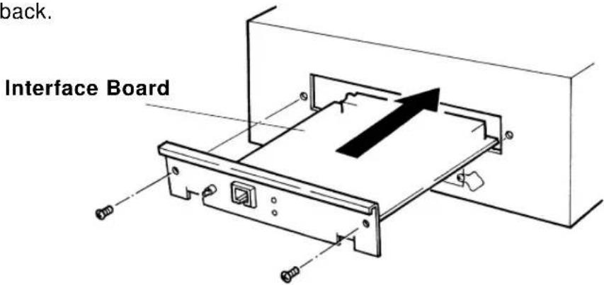
text_image
back. Interface BoardCAUTION
- Electronic components are susceptible to damage by static electricity. Remove static charge from your clothes and body by touching your hands to the board box before you touch the network interface board.
Step 3
Fasten the two interface mounting screws.
Step 4
Connect a Category 5 Ethernet cable compatible with both 10BASE-T and 100BASE-TX to the connector on the interface board. Connect the other end of the Ethernet cable to the 10BASE-T or 100BASE-TX network hub.

text_image
10BASE-T/100BASE-TX Compatible Ethernet Cable (Category 5)Memory Extension
Standard internal memory for the Falcon Outdoor printer is 8 MB + 32 MB (slot 1) but this can be extended by fitting an additional 16 MB (SIM16M) or 32 MB (SIM32M) memory chips (sold separately).
The following procedure explains how to install extended memory.

CAUTION
- The power to the printer must be switched off and the power cord removed before the additional memory is installed.
Step 1
Remove roll media and scroller from the printer. Undo the three screws holding the board box on the printer main unit and carefully lower the board box. Remove two thumb screws to reveal the memory slot.
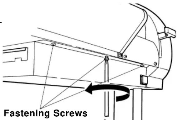
text_image
Fastening ScrewsBoard Box Fastening Screws

CAUTION
- Electronic components are susceptible to damage by static electricity. Remove static charge from your clothes and body by touching your hands to the board box before you touch the additional memory chip.
- Dust in the slot may cause damage. Blow it out with an air duster before installing the additional memory.
Step 2
The optional memory chip to be added should be inserted in slot 2 on the lower right of the board with the nicked end of the chip at the right hand end of the slot.
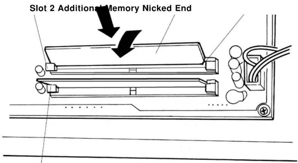
text_image
Slot 2 Additional Memory Nicked EndSlot 1 (already in use)
Step 3
Return the board box to its original position.
Details of the Display
This section explains about displays while the printer is working, messages when an error has occurred and how to deal with them.
| Printer Status Display | PAGE 172 |
| Messaged Errors and Countermeasures | PAGE 174 |
| Data error Display and Countermeasures | PAGE 177 |
| Command Error Display and Countermeasures | PAGE 178 |
| Errors Requiring a Restart | PAGE 180 |
Printer Status Display
The normal operating condition of the printer is displayed.
Normal (when media is loaded)
P I o t O K
Data can be received and printed.
Normal (when media is not loaded)
Paper End
Media is not loaded or printing on a cut sheet is finished. Data can be received but can not be printed unless media is loaded.
Lever up
Lever Up
The hold lever is up. Put the hold lever down.
Cover open
Cover Open
The cover is open. Close the cover.
Cover open, lever up
Lever and Cover
The cover is open and the hold lever is up. Close the cover and lower the hold lever.
Data reception in progress
Receive [Port1]
Data is being received. Printing will begin after the data has been processed.
Converting the data
Convert [Port1]
Data is being processed. Printing will begin after the data has been processed.
Printing in progress
Printing
Processed data is being printed.
Cleaning in progress
Cleaning
The print heads are being cleaned.
Please wait.
Media initialization in progress
Con firm Paper Kind
Media is being initialized. Please wait.
The normal operating condition of the Heater System is displayed on the Heater System Display.
The left of line 1\~line 3 shows the parameters of Front Heater and the right of line 1 \~line 3 shows the parameters of Rear Heater.
ST means "Set Temperature", which shows the last time temperature-set. There are four buttons used to set the temperature :
- Left-Up Button to increase Front ST
- Left-Down Button to decrease Front ST
- Right-Up Button to increase Rear ST
- Right-Up Button to decrease Rear ST
RT means "Real Temperature", which shows the Front Heater temperature and Rear Heater temperature detected by the sensors.
Line 4 shows the Heater running situation:
Heater running situation
Heater ON (F, R)
The Front and Rear Heater is ON.
Heater running situation
Heater ON (F)
The Front Heater is ON and the Rear Heater is Off.
Heater running situation
Heater ON (R)
The Front Heater is Off and the Rear Heater is ON.
Heater running situation
Heater Off
Both heaters are Off.
Heater running situation
Heater Standby
When the fans of the printer stops running for two minutes, the Heater System enters sleep status (saving energy).
Messaged Errors and Countermeasures
A messaged error impedes the operation of the printer. Sometimes an error is displayed and printing continues or printing may cease when an error is displayed. If printing stops, it will be reprinted when the cause of the error is removed.
When a messaged error occurs, the beeper will beep twice unless there is insufficient memory.
Capping position not set
No Cap Position
The capping position is not recorded. The error will not be cancelled until the capping position is adjusted. Contact your local Mutoh dealer regarding capping position adjustment.
Media recognition error
Undefined Paper
An error has occurred during media detection.
Either media smaller than the minimum size or larger than the maximum size was detected or the hold lever was up or a media jam occurred during media detection. This error also occurs if the media is not loaded in the correct position. Put the hold lever up and reload the media.
Media skew error
Paper Slant
Roll media has slipped obliquely. Reload the media.
Media replacement error
Paper Cut Error
Roll media cutting failed. Cut the media, raise the hold lever and reload the media.
Media replacement request
| Remove Media |
Media is loaded but the next process has failed. The lever was raised during printing or cutting and lowered again without the media having been removed. Remove the media.
Roll media end
| End of Roll |
The end of the media was detected when roll media was initialized. Replace the roll media.
No waste box
| No Waste - Ink Tank |
The waste bottle is not installed. Install a waste bottle.
Check waste box
| Check Waste Ink |
The waste bottle is becoming full.
Waste box full
| Full Waste Ink Tank |
The waste bottle is full of waste liquid. Take out the waste bottle and empty the waste bottle. Re-install a waste bottle.
Request to insert ink cartridges of the same type
| Ink Change |
The type of ink cartridges was changed (from dye to pigment or from pigment to dye) during cleaning or ink filling. Replace with original cartridge type.
Request to insert exclusive or same type ink cartridges
Differ Ink Kind
Either ink cartridges other than the exclusive type or mixed dye and pigment ink cartridges have been installed. Make sure exclusive ink cartridges of the same type are loaded.
Low ink warning
[65YMCK] Near En
d The remaining ink is low. Prepare a new ink cartridge of the color that is displayed.
No ink
[65YMCK] Ink End
The ink cartridge of the color that is displayed is empty. Replace with a new cartridge.
1 to 5 ink cartridges missing
[65YMC] Cartridg
e The ink cartridge of the color that is displayed is not installed. Insert a cartridge.
All ink cartridges missing
Cartridge None
No ink cartridges are installed. Insert cartridges.
Insufficient memory
No Memory SIMM12MB
There was insufficient memory during data processing or printing. In this case the beeper gives three long beeps. Printing continues but the result can not be guaranteed. Since the required memory size is displayed, you should consider extending the memory.
Data Error Display and Countermeasures
Data errors occur when there is a fault in communication between the printer and the computer. There are three types of data error:
- Errors related to communication conditions
- Errors caused by faulty handshaking
- Escape sequence command format errors
The beeper gives three long beeps when a data error occurs.

NOTE
- The command that caused the error may be shown enclosed in brackets in the data error message.
Network board detection error
Netw. Check Err
A board other than a prescribed network interface board has been installed. Replace with a prescribed network interface board.
Network board initialization error
Netw. Init. Err
An error occurred when the network interface board was installed. The network interface board may be faulty. Replace the network interface board.
Command Error Display and Countermeasures
Command errors occur during the processing of command data received from the computer.
If the printer's command set-up differs from the type of command data sent from the computer
If there is a grammatical error in the command data sent from the computer
The beeper gives three long beeps when a data error occurs.

NOTE
- A command error may occur together with a data error (related to error code I15). In this case the communication settings should be checked.
- The command that caused the error may be shown enclosed in brackets in the data error message.
Undefined command error
MH0 1 Error [ ]
A command that is undefined by MH-GL command mode was analyzed.
Parameter error
MH02 Error [ ]
An invalid number of parameters follow the command.
Numerical value error
MH0 3 Error [ ]
An invalid parameter follows the command.
Undefined character set
MH0 4 Error [ ]
A non-existent character set has been selected.
Position overflow
MH06 Error [ ]
Buffer overflow
MH0 7 Error [ ]
The polygon buffer or downloadable buffer has overflowed.

NOTE
- In each case, first check that the command modes of the computer and printer are compatible. Refer to your computer manual for computer settings.
Errors Requiring a Restart
Errors requiring a restart are fatal to the operation of the printer. The power to the printer must be switched off and the printer must be restarted. They are caused by an obstruction to the printer drive or damage related to a printer board.
When an error requiring restart occurs, the printer behaves as follows.
(a)Drive power is shut down automatically.
(b) All LEDs on the control panel flash and the beeper sounds continuously. The beeper will not stop until a key is pressed.
(c) An error code and error name are displayed in the liquid crystal display section.
Errors Requiring Restart that Involve the Mechanical System
If an error has occurred in the mechanical system, remove the foreign object, paper scraps, etc. that are causing the obstruction and restart the printer.
Feed motor error
| E 0 6 5 Err X Motor |
Carriage motor error
| E 0 6 6 Err Y Motor |
Feed encoder error
| E069Err Xencoder |
Carriage encoder error
| E070Err Yencoder |
Feed imposition timeout
| E071Err Xtimeout |
Carriage imposition timeout
| E 0 7 2 Err Y t i m e o u t |
An error with the media feed motor has occurred.
An error with the carriage motor has occurred.
An error with the media feed encoder has occurred.
An error with the carriage encoder has occurred.
An error with the media feed imposition has occurred.
An error with the carriage imposition has occurred.
Feed motor overcurrent
E 0 7 3 E r r X c u r r e n t
An error with the media feed motor has occurred.
Carriage motor overcurrent
E 0 7 4 E r r Y c u r r e n t
An error with the carriage motor has occurred.

NOTE
- When an error occurs in the XY drive systems, check for an obstruction in the XY drive systems. If there is an obstruction, remove it before the power is switched on again.
Sensor detection error
E075Err Sensor
A sensor can not be detected.
NVRAM error
E 1 2 9 E r r N V R A M
An error has occurred when writing to the flash RAM.
Sum-check error
E016 CPUErr [35]
A flash RAM sum-check error has occurred.

NOTE
- In the case of a Sensor detection error, NVRAM error or Sum-check error, switch on the power again. If the error persists, contact your MUTOH local dealer.
Errors Requiring Restart that Involve the CPU System
Standard DRAM error
E001Err DRAM
An access error has occurred in standard DRAM.
Optional DRAM error
E002ErrOpt.DRAM
An access error has occurred in extended DRAM (option: sold separately).
Interrupt exception error
E016 CPUErr [00]
An interrupt exception error has occurred in the CPU.
Command environment exception error
E016 CPUErr [02]
A command environment exception error has occurred in the CPU.
Data environment exception error
E016 CPUErr [03]
A data environment exception error has occurred in the CPU.
Address exception error
E016 CPUER r [04]
An address exception error has occurred in the CPU.
Address exception error
E016 CPUErr [05]
An address exception error has occurred in the CPU.
Bus exception error
E016 CPUErr [06]
A bus exception error has occurred in the CPU.
Bus exception error
E016 CPUErr [07]
A bus exception error has occurred in the CPU.
Errors Requiring a Restart Errors Requiring Restart that Involve the CPU System
System call exception error
E016 CPUErr [08]
Break point exception error
E016 CPUErr [09]
Reserved command exception error
E016 CPUErr [10]
Unusable co-processor exception error
E016 CPUErr [11]
Operation overflow exception error
E016 CPUErr [12]
Trap exception error
E016 CPUErr [13]
Watch exception error
E016 CPUErr [22]
Watchdog timeout error
E016 CPUErr [32]
Abort error
E016 CPUErr [33]
A system call exception error has occurred in the CPU.
A break point exception error has occurred in the CPU.
A reserved command exception error has occurred in the CPU.
An unusable co-processor exception error has occurred in the CPU.
An operation overflow exception error has occurred in the CPU.
A trap exception error has occurred in the CPU.
A watch exception error has occurred in the CPU.
A watchdog timeout error has occurred in the CPU.
An abort error has occurred in the CPU.

NOTE
- In each case, switch off, wait 10 seconds and switch on.
Errors Requiring a Restart
Errors Requiring Restart that Involve the Heater System
- Errors shown on the Heater Control Panel (line 4).
Errors Requiring Restart that Involve the Heater System
Sensor error
| Err: F.R.T.sensor |
An error has occurred in the Front Right Temperature Sensor.
Sensor error
| Err: F.L.T.sensor |
An error has occurred in the Front Left Temperature Sensor.
Sensor error
| Err: R.L.T.sensor |
An error has occurred in the Rear Left Temperature Sensor.
Sensor error
| Err: R.R.T.sensor |
An error has occurred in the Rear Right Temperature Sensor.
Sensor error
| Err: FRFLT.sensor |
An error has occurred in the two Front Temperature Sensors.
Sensor error
| Err: | FRRLT.sensor |
An error has occurred in the Front Right and Rear Left Temperature Sensor.
Sensor error
| Err: FRRRT.sensor |
An error has occurred in the Front Right and Rear Right Temperature Sensor.
Sensor error
| Err: FLRLT.sensor |
An error has occurred in the Front Left and Rear Left Temperature Sensor
Sensor error
| Err: FLRRT.sensor |
An error has occurred in the Front Left and Rear Right Temperature Sensor
Errors Requiring a Restart Errors Requiring Restart that Involve the CPU System
Sensor error
Err: RRRLTsensor
Sensor error
Err: 2FRLTsensor
Sensor error
Err: 2FRRTsensor
Sensor error
Err: FR2RTsensor
Sensor error
Err: FL2RTsensor
Sensor error
Err: All T. sensor
Sensor error
Err: Heaters Stop
An error has occurred in the two Rear Temperature Sensors.
An error has occurred in both Front and in the Rear Left Temperature Sensor.
An error has occurred in both Front and in the Rear Right Temperature Sensor.
An error has occurred in both Rear and in the Front Right Temperature Sensor.
An error has occurred in both Rear and in the Front Left Temperature Sensor.
An error has occurred in all temperature sensors.
After 10 minutes Real temperature could not be reach. All heaters stop.

NOTE
- In the case of a Sensor detection error, switch on the power again. If the error persists, contact your MUTOH local dealer.
Daily Maintenance
This section gives details of maintenance that should be done every day (cleaning, ink cartridge replacement, etc.) as well as examples of troubles that might occur and how handle them.
| Cleaning the Printer | PAGE 188 |
| Replacing Ink Cartridges | PAGE 191 |
| Switching Inks | PAGE 192 |
| Replacing the Cutter | PAGE 196 |
| Replacing Waste Liquid Absorbent Sheet (Waste Ink Bottle) | PAGE 198 |
| Cleaning the Cleaning Wiper | PAGE 200 |
| When Trouble Strikes | PAGE 202 |
| Periodical Maintenance | PAGE 210 |
Cleaning the Printer
Wipe the printer with a soft cloth.
CAUTION
- Turn off the power switch when cleaning the printer.
- Don't use thinners or benzene, as these will damage the paint.
- When cleaning, don't open any covers that are fastened by screws as these contain electrical parts.
- Paper dust is produced when the printer is working. This should be wiped off periodically. Don't blow it away.
- For stubborn soiling that resists wiping, use a lint-free cloth moistened with alcohol.
Any scraps of paper clinging to the platen and cutter groove should be wiped off from right to left with a damp cloth.
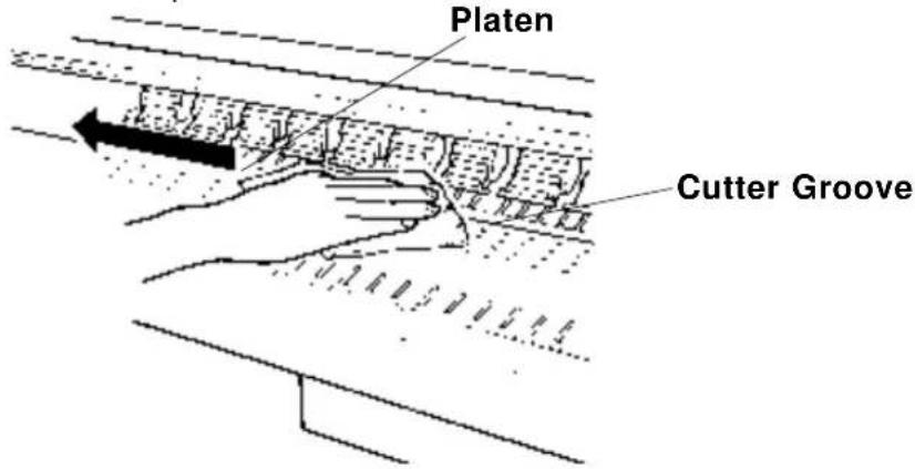
text_image
Platen Cutter Groove!IMPORTANT
- Dust and scraps of paper tend to accumulate over time on the platen and cutter groove. This leads to poor quality printing and cutting.
Use a soft damp cloth to wipe away any paper scraps clinging to the pressure roller.
Clean the drive roller with a nylon brush.
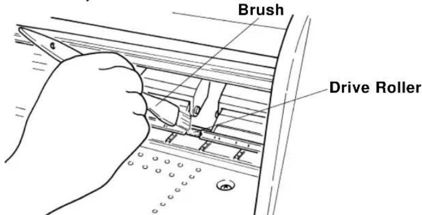
text_image
Brush Drive Roller!IMPORTANT
- Paper scraps on the pressure roller and drive roller may prevent the media from feeding properly and produce a "Jam check error".
Use a cotton swab to clean dust and paper scraps from the cover of the media sensor at the rear.
Bend the swab as shown in the diagram.
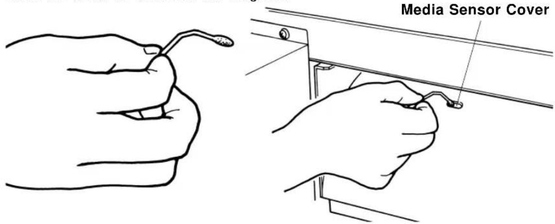
text_image
Media Sensor Cover!IMPORTANT
- Progressive soiling affects the sensitivity of the sensors and may cause media to be detected even when no media is loaded.
Replacing Ink Cartridges
If the Falcon Outdoor is displaying "No ink" or "No cartridge", the ink cartridge should be replaced or inserted without delay. If "Ink low" is displayed, have a replacement cartridge ready.
Step 1
If "No ink" is displayed in the message display section, from the back, pull out the ink cartridge for the color that is shown to be not printing. For example, if black ink has run out,
| [ | K | ] | N |
pull out the black ink cartridge.
| [ | K | ] | C |

text_image
e a r r t r EStep 2
Open the new ink cartridge package.

NOTE
- Only genuine ink cartridges can be used. They also need to be turned in the proper direction for insertion. Make sure not to confuse the direction and place for insertion.
- Open the ink cartridge just before you load it into the slot. Printing may be blurred if the ink cartridge is left open for a long time.
- Ink cartridges should be used within two years of the date that is printed on the package. Cartridges that have been loaded into the printer should be replaced within six months.
Step 3
Insert the new cartridge in the slot at the back of the printer.
Step 4
Check that the permanent message has been restored in message display section.
| P I o t O K |
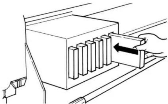
natural_image
Diagram of a hand inserting a block into a device (no text or symbols present)Switching Inks
Use the INK CHANGE procedure to switch from DYE ink to PIGMENTED ink or from PIGMENTED ink to DYE ink. Use the INK CHANGE procedure to switch from Dye or Pigmented Ink to ECO-SOLVENT INK.

Important :
After using Eco-Solvent ink it is not possible to change to other type of ink (pigmented and dye Inks).
Before installing and changing to Eco-Solvent ink, the machine needs to go through a cleaning cycle with special Eco-Solvent transition liquid.
When using this function, cleaning cassettes need to be installed to the cassettes slots.
| Plot OK | Step 1 :To enter the Menu system, press the [MENU] key. |
| * Menu * Command > | Step 2 :The key contents change to the yellow section on the outside of the control panel. Bring up the “Utility” menu by pressing the [Menu up] key or [Menu Down] key. |
| * Menu * Utility> | Step 3 :Press the [ENTER] key to enter the “Utility” menu and shift to the next level. |
| InkChange : No | Step 4 :Bring up the “InkChange” item by pressing the [Menu up] key or [Menu Down] key. |
| InkChange : Yes | Step 5 :Press the [Value/+] or [Value/-] key to select “Yes” and press ENTER. |
Switching Inks
| Change Waste Ink | Step 6 : Empty the waste ink bottles. |
| Change Tank ? Yes | Step 7 : Press the [Value/+] or [Value/-] key to select “Yes” and press ENTER. |
| ConfirmChange Yes | Step 8 : Press the [Value/+] or [Value/-] key to select “Yes” and press ENTER. |
| Remove Cart | Step 9 : Remove ink cartridges from the slot. |
| Set Wash Cart | Step 10 : Insert the cleaning cartridge to the ink cartridge slots. Use the special Eco-solvent Transition Liquid when changing to Eco-solvent ink. The head wash starts when the cleaning cartridge is inserted. The cleaning period is approximately 15 minutes. |
| Head Wash | |
| Remove Wash Cart | Step 11 : Remove the cleaning cartridge from the slot. |
| Head Wash | Step 12 : The rest of the cleaning fluid in the printer unit is discharged when the cleaning cartridge is removed. |
| Change Waste ink | Step 13 : Empty the waste ink bottle from the printer unit. |
Switching Inks
| Change Tank ? Yes | Step 14 :Press the [Value/+] or [Value/-] key to select “Yes” and press ENTER. |
| ConfirmChangeYes | Step 15 :Press the [Value/+] or [Value/-] key to select “Yes” and press ENTER. |
| [YMCK] Discharged | Step 16 :If the cassettes that have been removed are DYE ink cassettes, now insert PIGMENTED ink cassettes or ECO-SOLVENT ink cassettes.If the cassettes that have been removed are PIGMENTED ink cassettes, now insert DYE ink cassettes or ECO-SOLVENT ink cassettes. |

Important :
After using Eco-Solvent ink it is not possible to change to other type of ink (pigmented and dye Inks).
| Ink Refill | 4M |
| Ink Refill | 3M |
| Ink Refill | 2M |
| Ink Refill | 1M |
Step 17 :
The initial fill is executed when installing cartridges.
The display will show the following messages :
| Ink Refill | 0M |
| Ink Refill | 4M |
| Ink Refill | 3M |
| Ink Refill | 2M |
| Ink Refill | 1M |
| Ink Refill | 0M |
Plot OK
Step 18 :
After filling, the display will show the following message :

Note :
- The cleaning cartridge is one time use only.
- Only recommended ink cassettes can be used. The also need to be turned in the proper direction for insertion.
- Ink cassettes should be used within two years of the date that is printed on the package. Cassettes that have been loaded into the printer should be replaced within six months.
Replacing the Cutter
Depending on the type of roll media used, paper dust accumulating on the cutter groove and cutter tip may lead to poor cutting. In this case, the cutter tip should be cleaned or replaced and the cutter groove should be cleaned. The cutter is a consumable item. If it is not sharp, replace it. One cutter should last for about 1000 cuts (about 20 rolls) so it should be replaced periodically.
Step 1
Switch off the power, lower the hold lever and bring the head to the middle.
CAUTION
- Don't move the head with the hold lever up. The head and media keeper blade may touch, causing damage and poor printing quality.
Step 2
Hold the cutter down with your finger, turn the cutter arm forward and remove the cutter. Clean the cutter blade with a dry cloth or replace the cutter.

text_image
Cutter ArmCAUTION
- There is a spring in the hole of the cutter holder. Be careful not to lose it when the cutter is replaced.
Step 3
Insert a new cutter blade in the hole in the head. Press down on the cutter while you return the cutter arm over the cutter. The cutter will only fit in one direction.

natural_image
Technical line drawing of a mechanical assembly with mounting holes and internal components (no text or symbols)
CAUTION
• The cutter blade is very brittle. Be careful not to bump it or drop it.
Step 4
Be sure to return the head to the right by hand before switching on the power.

NOTE
- Cutter life will vary according to the type and thickness of the media and the usage environment, so you should always keep a spare cutter blade handy.
Replacing Waste Liquid Absorbent Sheet (Waste Ink Bottle)
When printing A0 size or larger widths, very small amounts of ink will be ejected on the left edge for stable printing quality. The waste ink ejected on the left side in that way is collected in a translucent bottle under the main unit (the waste ink bottle).
text_image
Waste Ink BottleStep 1
Since there is no panel display or lamp display when the waste liquid absorbent sheet in the waste ink bottle is to be replaced, you should prepare to replace the waste liquid absorbent sheet when you see that the bottle is about half full. Have a new absorbent sheet, a thick vinyl bag and a pair of forceps ready.

NOTE
- Conditions vary for the waste ink bottle to become half full but it will be after printing about 2000 A0 pages.
Step 2
Remove the waste ink bottle by turning it to the left. Using absorbent sheet and forceps, soak up the waste liquid in the bottle and discard the waste liquid absorbent sheet into the open vinyl bag.

natural_image
Line drawing of two hands using a tool to apply liquid into a bottle (no text or symbols)Step 3
The waste ink bottle, fitted with new waste liquid absorbent sheet, is installed in the printer by turning it to the right.

CAUTION
- The used waste liquid absorbent sheet should be disposed of as non-combustible material in accordance with your local civic regulations.
- It would dangerous for children to lick or swallow the absorbent sheet filled with waste liquid, so dispose of it promptly or put it out of reach.
- If you accidentally touch the waste liquid, wash with soap and water at once.
- If it should enter your eye, wash with plenty of water and see a doctor. If it is licked, gargle with water and wash out straight away. If it is swallowed, immediately drink plenty of water and consult a doctor without delay.
Cleaning the Cleaning Wiper
When the head is cleaned and the type of ink is changed frequently, waste matter clinging to the cleaning wiper may cause the printing to become faint or blemished. In such cases, you should clean the cleaning wiper.
Step 1
Switch off the power, lower the hold lever and bring the head to the middle.

CAUTION
- Don't move the head with the hold lever up. The head and media keeper blade may touch, causing damage and poor printing quality.
Step 2
Clean the cleaning wiper backwards and forwards two or three times with the cloth for cleaning the cleaning wiper (an accessory item).
text_image
Head Cap Unit Cleaning Wiper
CAUTION
- Clean without your hand coming into direct contact with the head cap unit, which is near the cleaning wiper. Otherwise oil may get on the cleaning wiper and it will be unable to clean the head properly.
- Don't lift up the cleaning wiper when you are cleaning it. Otherwise it be unable to clean the head properly.
- The cleaning wiper and its surroundings will be soiled with waste liquid. Be careful not to dirty your hands and clothes.
Step 3
Return the head to its former position at the right hand end of the printer.

CAUTION
- The head may be damaged by drying ink, etc. if it is not returned to the right hand end of the printer.

NOTE
- After the cleaning wiper has been cleaned, if head cleaning does not make the faintness or blemishing in the printing disappear, contact your local Mutoh dealer.
When Trouble Strikes
If you have trouble that you think may be a malfunction when you are using the Falcon Outdoor, first check the details on the following tables (trouble-shooting).
!IMPORTANT
- If you are to receive service, please have your warranty document ready. If you can not produce it, it may not be possible to check the warranty period and you may be charged for service, even though it is within the warranty period. Similarly, in the case of a service contract, please have your contract document available.
Nothing happens after power is switched on
| Possible Cause Remedy | Reference Page | |
| (1) Is the power cable connected? | Connect the power cable. | Page 37 |
| (2) Is the AC power supply at the specified voltage? | Use specified voltage. | Page 18 |
| (3) Is the printer cover open, or the hold lever up? | Close the cover. Put the hold lever down. | Page 19 |
Nothing happens after media is loaded
| Possible Cause Remedy | Reference Page | |
| (1) Is the printer cover open, or the hold lever up? | Close the cover. Put the hold lever down. | Page 19 |
| (2) Is the media loaded obliquely? | Load the media straight. | Page 48 |
| (3) Are ink cartridges installed? | Install ink cartridges. | Page 40 |
Nothing happens after the computer sends data
| Possible Cause Remedy | Reference Page | |
| (1) Is the interface cable connected? | Refer to "Connecting the interface cable". | Page 67 |
| (2) Are ink cartridges installed? | Install ink cartridges. | Page 40 |
| (3) Do they contain ink? | Replace ink cartridges. | Page 191 |
| (4) Have you replaced the waste bottle? | Replace waste bottle. | Page 198 |
When printer sends data, the printer shows and error and does not print
| Possible Cause Remedy | Reference Page | |
| (1) Does the computer have the proper type of equipment selected? | Check that the equipment type settings are the same on both the computer and printer. (Refer to "To receive data from the computer". | Page 68 |
| (2) Do interface conditions and command modes match on both computer and printer? |
#Parts of the print are dirty or missing

NOTE
- If the media is not media specified by Mutoh, you may be unable to obtain proper printing quality.
| Possible Cause Remedy | Reference Page | |
| (1) Is the media damp? | Replace with new media. | Page 48 |
| (2) Are you using creased or wrinkled media? |
It prints but the position is not right (there are places that cannot be printed)
| Possible Cause Remedy | Reference Page | |
| (1) Is the media loaded in the right position? | Load media correctly. | Page 48 |
| (2) Have you made scale or mirror settings? | Cancel scale and mirror settings or repeat the set-up. | Page 126 and 127 |
| (3) Is an initial position specified? | Cancel initial position setting or repeat the set-up | Page 122 |
| (4) Is the printing abnormal after ink was filled? | Leave for 24 hours after ink filling and try printing again | Page 38 |
#Media jams occur frequently

NOTE
- If the media is not media specified by Mutoh, proper media feeding can not be guaranteed.
| Possible Cause Remedy | Reference Page | |
| (1) Are you using media spec-ified by Mutoh? | Use media specified by Mutoh. | Page 48 |
| (2) Is your usage environ-ment other than that spec-ified? | Use in the specified environ-ment. | Page 18 |
| (3) Are you using old media? | Replace with new media. | Page 48 |
| (4) Is the media creased or wrinkled? | Replace with new media. | Page 48 |
Roll paper is not cut cleanly
| Possible Cause Remedy | Reference Page | |
| (1) Is the cutter sharp? | Replace cutter. | Page 196 |
| (2) Is the media charged with static electricity? | Remove static charge. | |
| (3) Are you using cloth? | Cut cloth manually. | Page 71 |
Ink initial filling fails
| Possible Cause Remedy | Reference Page | |
| (1) Is the printer cover open, or the hold lever up? | Close the cover, put the hold lever down. | Page 19 |
| (2) Are all six ink cartridges inserted right to the back? | Insert all six cartridges properly. | Page 40 |
| (3) Do all six ink cartridges have the type of ink? | Insert all six cartridges of the same type. | Page 40 |
Ink does not appear even after initial filling
| Possible Cause Remedy | Reference Page | |
| (1) Is the ink cartridge cold and frozen? | Leave for at least 3 hours at room temperature (25°C) then do cleaning several times. | Page 38 |
| (2) Was the power cut during initial filling? | Switch on again and continue with initial filling. | |
| (3) Sometimes the printer seems unable to print nor-mally after initial filling | Do several cleanings and check each time. | Page 156 |
Media comes off or is torn during media initialization
| Possible Cause Remedy | Reference Page | |
| (1) Are you using media spec-ified by Mutoh? | Use media specified by Mutoh. | Page 48 |
| (2) Is the hold lever down? | Put the hold lever down. | Page 19 |
| (3) With cut media, is the leading edge aligned with the edge of the printing board? | Load cut media with the lead-ing edge aligned with the edge of the printing board. | Page 49 |
| (4) With roll media, does the right hand edge of the media move parallel to the guide line during media detection? | Load roll paper correctly so that it moves parallel to the guide line. | Page 52 |
| (5) Is the scroller mounted correctly? | Mount the scroller correctly. | Page 52 |
| (6) Is any foreign matter such as media scraps clinging to the drive roller? | Clean the drive roller. | Page 188 |
| (7) Is the media sensor dirty? | Clean the media sensor. | Page 188 |
| (8) Are you using the printer in a place outside the usage environment, such as in direct sunlight? | Bring the environmental conditions for using the printer in line with the specified environment. | Page 18 |
Media wrinkles during media initialization
| Possible Cause Remedy | Reference Page | |
| (1) Are you using media spec-ified by Mutoh? | Use media specified by Mutoh. | Page 48 |
| (2) Is the hold lever down? | Put the hold lever down. | Page 19 |
| (3) With cut media, is the leading edge aligned with the edge of the printing board? | Load cut media with the lead-ing edge aligned with the edge of the printing board. | Page 49 |
| (4) With roll media, does the right hand edge of the media move parallel to the guide line during media detection? | Load roll paper correctly so that it moves parallel to the guide line. | Page 52 |
| (5) Is the media loaded obliquely? | Load the media straight. | Page 49 |
| (6) Is any foreign matter such as media scraps clinging to the drive roller? | Clean the drive roller. | Page 188 |
| (7) Are you using the printer in a place outside the usage environment, such as in the draft from an air conditioner? | Bring the environmental condi-tions for using the printer in line with the specified environ-ment. | Page 18 |
Thin media is not detected
| Possible Cause Remedy | Reference Page | |
| (1) Are you using media spec-ified by Mutoh? | Use media specified by Mutoh. | Page 48 |
| (2) Are you using the printer in a place outside the usage environment, such as in direct sunlight? | Bring the environmental condi-tions for using the printer in line with the specified environ-ment | Page 18 |
Wrong media size in media initialization
| Possible Cause Remedy | Reference Page | |
| (1) Are you using media spec-ified by Mutoh? | Use media specified by Mutoh. | Page 48 |
| (2) Is the hold lever down? | Put the hold lever down. | Page 18 |
| (3) Is the media loaded obliquely? | Load the media straight. | Page 48 |
| (4) Does media tend to curl up when it is loaded? | Remove the tendency to curl or load new media. | Page 48 |
| (5) Are you using the printer in a place outside the usage environment, such as in the draft from an air conditioner? | Bring the environmental condi-tions for using the printer in line with the specified environ-ment. | Page 18 |
| (6) Is the media sensor dirty? | Clean the media sensor. | Page 188 |
| (7) Are you re-using media that has already been printed? | Use new media. | Page 48 |
Media is skewed during printing
| Possible Cause Remedy | Reference Page | |
| (1) Are you using media spec-ified by Mutoh? | Use media specified by Mutoh. | Page 48 |
| (2) Is the hold lever down? | Put the hold lever down. | Page 19 |
| (3) With roll media, does the right hand edge of the media move parallel to the guide line during media detection? | Load roll media correctly so that it moves parallel to the guide line. | Page 52 |
| (4) Is the scroller mounted correctly? | Mount the scroller correctly | Page 52 |
Can't install printer driver
| Possible Cause | Remedy | ReferencePagePage 70Page 70 |
Can't go online with Centronics
| Possible Cause Remedy | Reference Page | |
| (1) Is the Centronics interface cable connected properly? | Connect the Centronics interface cable properly. | Page 27 |
| (2) Does the DATA LED on the control panel light up when the application sends the printing data? | If the DATA LED does not light up, contact the application supplier or the computer supplier. | |
| (3) Does the printer's Centronics setting mode and timing agree with the environment on the computer side? | Align the printer's Centronics settings with the timing on the computer side. | Page 136 |
| (4) Does the command type that is currently set-up match on the application and on the driver side? | Set up user set-up commands. | Page 113 |
Printed line is blurred
| Possible Cause Remedy | Reference Page | |
| (1) Are you using media spec-ified by Mutoh? | Use media specified by Mutoh. | Page 48 |
| (2) Are you using thick media and thin media? | Use media specified by Mutoh. | Page 48 |
| (3) Are you using ordinary paper? | Use media specified by Mutoh. | Page 48 |
| (4) Are you printing on the printing side of the media? | Check the printing side of the media and load it correctly. | Page 48 |
| (5) Have you tried head cleaning? | Try head cleaning. Use power-ful cleaning. | Page 156 |
White and black bands appear in printing
| Possible Cause Remedy | Reference Page | |
| (1) Are you using media spec-ified by Mutoh? | Use media specified by Mutoh. | Page 48 |
| (2) Is the hold lever down? | Put the hold lever down. | Page 19 |
| (3) Is the pressure roller posi-tioned correctly relative to the media? | Align the pressure roller with the media and position it cor-rectly. | Page 48 |
| (4) Is the scroller mounted correctly? | Mount the scroller correctly. | Page 52 |
Printed lines do not join
| Possible Cause Remedy | Reference Page | |
| (1) Are the ink cartridges out of date? | Replace with new ink cartridges. | Page 191 |
| (2) Are you using media specified by Mutoh? | Use media specified by Mutoh. | Page 48 |
| (3) Have you tried head cleaning? | Try head cleaning.Use powerful cleaning. | Page 156 |
| (4) Is the ink cartridge cold and frozen? | Leave for at least 3 hours then do cleaning several times. | Page 156 |
| (5) Did you try the fine adjustment of printing quality? | Do a fine adjustment of printing quality. | Page162 |
PERIODICAL MAINTENANCE
You have to change some parts of the Falcon Outdoor printer to obtain a good quality. Please refer to the tables for an overview of periodical maintenance.
You will notice that the X-marks indicate a renewal of the mentioned part(s) after this many months. You have to change the absorbents every week.

IMPORTANT :
Note that the x-marks in month 6 and month 12 are only to be done by authorised Mutoh technicians.
Maintenance cycle on Falcon Outdoor 46 "
| Description | Qty | Monthly | |||||||||||||||
| 1 | 2 | 3 | 4 | 5 | 6 | 7 | 8 | 9 | 10 | 11 | 12 | ||||||
| Head | 2 | X | |||||||||||||||
| Flush | Box | Spare | Part | 1 | X | ||||||||||||
| W | i | p | e | r | 1 | X | X | ||||||||||
| Sensor | on | ext. | Waste | Bottle | syst. | 1 | |||||||||||
| Maint. | Station | GA | Assy | RJ-6100 | 1 | X | |||||||||||
| Waste | Connection | tube | small | 2 | X | ||||||||||||
| D | u | s | t | r | e | m | o | v | a | l | i | n | f | a | n | ||
| Cleaning | maintenance | Station | - | X | |||||||||||||
| Cleaning | bottle | 1 | X | ||||||||||||||
| Blade | on | press | roller | 4100/6100P | 18 | ||||||||||||
| F-absorbent 1 RJ-4100 | 4 | WEEKLY | |||||||||||||||
Maintenance cycle on Falcon Outdoor 62 "
| Description | Qty | Monthly | |||||||||||||
| 1 | 2 | 3 | 4 | 5 | 6 | 7 | 8 | 9 | 10 | 11 | 12 | ||||
| Head | 2 | X | |||||||||||||
| Flush | Box | Spare Part | 1 | X | |||||||||||
| W | i | p e r | 1 | X | X | ||||||||||
| Sensor | on | ext. Waste | Bottle | syst. | 1 | ||||||||||
| Maint. | Station | GA Assy | RJ-6100 | 1 | X | ||||||||||
| Waste | Connection | tube | small | 2 | X | ||||||||||
| D | u | s t r e | m | o | v | a | l | i | n | f | a | n | |||
| Cleaning | maintenance | Station | - | X | |||||||||||
| Cleaning | bottle | 1 | X | ||||||||||||
| Blade | on | press roller | 4100/6100P | 24 | |||||||||||
| F-absorbent 1 RJ-4100 | 4 | WEEKLY | |||||||||||||
Appendix
This section deals with printer specifications, optional items, supply items.
| Printer Specifications | PAGE 212 |
| Interface Specifications | PAGE 213 |
| List of Optional and Supply Items | PAGE 216 |
Printer Specifications
Falcon Outdoor 46" & Falcon Outdoor 62", affordable outdoor printers.
| Specifications | |
| Model names + types | 46” – 4/6 colour channels62” – 4/6 colour channels |
| Print Speed 14.49 m^2/h (360 x 180 | dpi)3.6 m^2/h (720 x 720 dpi)0.68 m^2/h (1440 x 1440 dpi) |
| Falcon Outdoor 46” width Falcon Outdoor 62” | 1180 mm Maximum Media1574.8 mm |
| Falcon Outdoor 46” Width Falcon Outdoor 62” | 1160 mm Maximum Print1554.8 mm |
| Resolutions High Speed Production High Quality | 360 x 180 dpi720 x 720 dpi1440 x 1440 dpi |
| Printing Technology Drop-on-demand Piezo Electric – MicrodotTM | |
| Ink Consumption 360 dpi : 4.66 ml/m^2 720 dpi : 7.98 ml/m^2 | |
| Ink tank capacity 220 ml ink cassettes | |
| Print Mode Options Draft (1 & 2 pass), Normal (2 & 4 pass) and Quality (8 & 16 pass) | |
| Print Control Options Media Microstep Adjust, Origin Reset, AutomaticImage Centering, Closed-Loop proprietary Colour Calibration system | |
| Ink Tank Options Eco-Solvent Ink | |
| Automatic take-up System Standard (Motorized Automatic / 200 Foot Media Capacity) | |
| LCD display 4 line x 20 Characters with LED Backlight | |
| Media Handling Front Feed with Front Exit Sheet / Rear Feed with Front Exit Roll | |
| Media drying System Pre- and post heaters | |
| Media Cutter Horizontal auto-cutting | |
| Media Core ∅ | Standard 2” and 3” media core |
| Software | RIP software included |
Specifications are liable to changes without prior notice. All trademarks mentioned are property of their respective owners.
Interface Specifications
Centronics Interface Specifications
(Bi-directional Parallel Interface: IEEE1284 Compatible)
| Modes Compatible, Nibble, ECP | |
| Port Port 1 | |
| Data Length 8 bits | |
| Transmission Direction Unidirectional (receive only), Bidirectional | |
| Connector Pin Numbering |  |
Parallel interface pin numbers and signals
| Pin No. | Name of signal No. | Signal Direction | Pin | Name of signal | Signal Direction |
| 1 | STROBE RJ Printer <- 19 SG | ||||
| 2 | DATA1 RJ Printer <- - > 20 SG | ||||
| 3 | DATA2 RJ Printer <- - > 21 SG | ||||
| 4 | DATA3 RJ Printer <- - > 22 SG | ||||
| 5 | DATA4 RJ Printer <- - > 23 SG | ||||
| 6 | DATA5 RJ Printer <- - > 24 SG | ||||
| 7 | DATA6 RJ Printer <- - > 25 SG | ||||
| 8 | DATA7 RJ Printer <- - > 26 SG | ||||
| 9 | DATA8 RJ Printer <- - > 27 SG | ||||
| 10 | ACK | RJ Printer -> 28 | SG | ||
| 11 | BUSY | RJ Printer -> 29 | SG | ||
| 12 | P ERROR | RJ Printer -> 30 | SG | ||
| 13 | SELECTED | RJ Printer -> 31 | INIT | RJ | Printer <- |
| 14 | AUTOFD RJ Printer <- 32 FAULT | RJ Plotter -> | |||
| 15 | not used | 3 not used | |||
| 16 | SG | 4 not used | |||
| 17 | FG | 5 not used | |||
| 18 | + 5V | 6 SELECTIN | RJ Printer <- | ||
Recommended Specifications for Centronics Interface Cable
| Interface IEEE1284 (bidirectional parallel) compatible | |
| Cable Type AWG28 x 18 pair (twisted pairs) | |
| Shield Type Metal tapes and braiding (double-shielded cable) | |
| Characteristic Impedance | 62Ω |
Network Interface (option) Specifications
| Port Port 2 (only when optional interface board is fitted) | |||
| Network Type | Ethernet IEEE802.3 | ||
| Network I/F 10 | BASE-T/100BASE-TX * Automatic switching type* Switching type(RJ-45 connector, twisted pair cable, category 5) | ||
| Protocol TCP/IP Mode • ftp • Rem | NetWare (V3.1) Remote printer mode • lpr • Print server • socket | J) EtherTalk de • Printer name • Zone name | |
| Spool Memory | 384 KB | ||
| Functions • Automatic protocol recognition | |||
List of Optional and Supply Items
- Interface Extension Board
| Name of Item Model Number Qty. | ||
| Ethernet interface board (10/100BASE-T) | RJ-ETH14TX | 1 set |
- Extended Memory
| Name of Item Model Number Qty. |
| Extended memory 16 MB SIM 16M 1 unit |
| Extended memory 32 MB SIM 32M 1 unit |
- Other Options
| Name of Item Model Number Qty. | ||
| 46-inch scroller (for 3-inch paper tube) | RJ6146-SR03 | 1 unit |
| Scroller 3" | ||
| 46-inch scroller (for 2-inch paper tube) | RJ6146-SR02 | 1 unit |
| Scroller 2" | ||
| 62-inch scroller (for 3-inch paper tube) | RJ6162-SR03 | 1 unit |
| Scroller 3" | ||
| 62-inch scroller (for 2-inch paper tube) | RJ6162-SR02 | 1 unit |
| Scroller 2" | ||
• Pigmented Ink Cartridges (220 ml)
| Name of Item Model Number Qty. | ||
| Pigment ink cartridge K (black) | RJ40P-22-BK | 1 unit |
| Pigment ink cartridge C (cyan) | RJ40P-22-CY | 1 unit |
| Pigment ink cartridge M (magenta) | RJ40P-22-MA | 1 unit |
| Pigment ink cartridge Y (yellow) | RJ40P-22-YE | 1 unit |
| Pigment ink cartridge O (orange) | RJ60P-22-OR | 1 unit |
| Pigment ink cartridge G (green) | RJ60P-22-GR | 1 unit |
• Dye Ink Cartridges (220 ml)
| Name of Item Model Number Qty. | ||
| Dye ink cartridge K (black) | RJ40D-22-BK | 1 unit |
| Dye ink cartridge C (cyan) | RJ40D-22-CY | 1 unit |
| Dye ink cartridge M (magenta) | RJ40D-22-MA | 1 unit |
| Dye ink cartridge Y (yellow) | RJ40D-22-YE | 1 unit |
| Dye ink cartridge LM (Light Magenta) | RJ60D-22-LM | 1 unit |
| Dye ink cartridge LC (Light Cyan) | RJ60D-22-LC | 1 unit |
- Cutter
Name of Item Model Number Qty.
Cutter blade RJ8-CBS 1 unit
• Eco-Solvent Ink Cartridges (220 ml)
Name of Item Model Number Qty.
| Eco-Solvent ink cartridge K (black) | RJ60L-22-BK | 1 unit |
| Eco-Solvent ink cartridge C (cyan) | RJ60L-22-CY | 1 unit |
| Eco-Solvent ink cartridge M (magenta) | RJ60L-22-MA | 1 unit |
| Eco-Solvent ink cartridge Y (yellow) | RJ60L-22-YE | 1 unit |
| Eco-Solvent ink cartridge LM (Light Magenta) | RJ60L-22-LM | 1 unit |
| Eco-Solvent ink cartridge LC (Light Cyan) | RJ60L-22-LC | 1 unit |
- Ink Switching Set
Name of Item Model Number Qty.
Ink Switching Set RJ6-CLEAN 1 unit
- Cleaning Cassette
Name of Item Model Number Qty.
Cleaning Cassette RJ-CLEANING 1 unit
- Eco-Solvent Transition Cassette
Name of Item Model Number Qty.
Eco-Solvent Transition Cassette RJ60L-22-CLN 1 unit