XJ (2000) - Car JAGUAR - Free user manual and instructions
Find the device manual for free XJ (2000) JAGUAR in PDF.

User questions about XJ (2000) JAGUAR
0 question about this device. Answer the ones you know or ask your own.
Ask a new question about this device
Download the instructions for your Car in PDF format for free! Find your manual XJ (2000) - JAGUAR and take your electronic device back in hand. On this page are published all the documents necessary for the use of your device. XJ (2000) by JAGUAR.
USER MANUAL XJ (2000) JAGUAR
This handbook forms part of the Owner literature supplied with your new vehicle.
Left-hand drive and right-hand drive conditions may be shown in the graphics and where information is specific to a particular country, it is indicated as such.
The Quick start section is designed to rapidly familiarise the driver with the initial set up and also explain some of the unique features. Please take the time to study the operating instructions with your vehicle as soon as you can.
Important
The information contained in this handbook covers all vehicle derivatives and optional equipment. Some of the options will not be fitted to your vehicle unless they formed part of the original vehicle specification; therefore some parts of this handbook will not apply to your vehicle. Furthermore, due to printing cycles, it may include descriptions of options before they become generally available.
The information contained in this publication was correct when it went to print. Vehicle design changes may have been made after this handbook was printed. When this occurs a handbook supplement is added to the literature pack. Subsequent updates can be viewed on the Jaguar Internet site at; www.ownerinfo.jaguar.com.
In the interest of development, the right is reserved to change specifications, design or equipment at any time without notice and without incurring any obligations. This publication, or part thereof, may not be reproduced nor translated without our approval. Errors and omissions excepted.
©Jaguar Cars Limited
All rights reserved.
Published by Jaguar Technical Communications.
Handbook Contents
Owner Information
General Information. 5
Data Recording 11
Health and Safety 12
Security and Locks
Ignition Switch....14
Vehicle Security....15
Door Locks 20
Luggage Compartment ..... 28
Alarm Systems 29
Garage Door Opener....33
Radio Frequency Approvals ..... 37
Before Driving
Occupant Protection 40
Child Safety....58
Seats 68
Clock 73
Steering Column 74
Pedal Controls....76
Door Windows....77
Mirrors 80
Driving Position Memory 84
Luggage Compartment 86
On the Road
Instruments 87
Message centre....97
Trip Computer 106
Exterior Lighting 109
Interior Lighting 114
Parking Assist 116
Horn. 119
Sunroof 120
Wipers and Washers 122
Parkbrake 124
Interior Features 125
Engine Starting 131
Transmission 134
Cruise (Speed) Control ..... 137
Adaptive Cruise Control (ACC) ..... 139
Automatic Speed Limiter.....145
Stability Control 147
Braking System 149
Suspension 151
Driving Information 152
Fuel and Refuelling 157
Climate Control
Climate Control 165
Front Climate Controls ..... 168
Rear Climate Controls 172
Touch-screen Climate Control .... 174
Roadside Emergency
Inertia Switch.... 184
Emergency Starting 185
Wheel Changing 187
Vehicle Recovery 194
Bulb Renewal.... 197
Fuses 203
Fire Extinguisher 213
Maintenance
General Maintenance. 214
Bonnet Release 215
Regular Checks 216
Checking and Top-up 217
Battery 226
Wiper Blades 230
Wheels and Tyres 231
Vehicle Care. 239
Electrical Accessories 242
Specifications
Engine Data 243
Dimensions 244
Weights 245
Load Weights. 248
Wheels and Tyres 249
Fuel Consumption Figures. 251
Touch-screen
Touch-screen. 252
Touch-screen Display 256
Handbook Contents
Audio System
Audio System 260
Steering Wheel Controls ..... 262
Radio 263
Digital audio broadcasting (DAB) ... 277
DAB Touch-screen 279
Single CD Player 286
Compact Disc Changer.....289
Television
TV General Information ..... 293
TV Basic Controls 294
TV Tuning 297
Teletext 302
Telephone
Telephone Introduction ..... 304
Telephone System 307
Telephone Operation - Standard ... 311
Telephone Operation - Touch-Screen .. 315
Phone Book. 320
Declaration of Conformity ..... 322
Voice Control
JaguarVoice 323
General Information
INTRODUCTION
Whether you are new to the Jaguar marque or have previously owned Jaguar or Daimler vehicles, we are pleased that you have made Jaguar your choice of vehicle this time.
When left-hand or right-hand is used in the text, this refers to the left-hand side or right-hand side of the vehicle, viewed from the rear.
For safety and the pleasure you will get from your new vehicle, please take the time to get well acquainted with your vehicle by reading the handbooks.
This Handbook describes every option and model variant available and therefore some of the items covered may not apply to your particular vehicle.
Note: Remember to pass on the vehicle handbooks when reselling the vehicle. Handbooks are integral parts of the vehicle.
WARNINGS, CAUTIONS AND NOTES
Take particular note of WARNINGS, Cautions and Notes given throughout this handbook.

WARNING:
Safety warnings are included in this handbook. These indicate either a procedure which must be followed precisely, or information that should be considered with great care in order to avoid the possibility of personal injury.
Caution: Cautions are included in this handbook. These indicate either a procedure which must be followed precisely, or information that should be considered with great care in order to avoid the possibility of damage to your vehicle.
Note: A note is a procedure which will help avoid difficulties in the operation of the vehicle.
Warning symbols on the vehicle


JOL2756
On encountering the warning triangle or open book symbol on the vehicle, it is important that before touching this part of the vehicle or attempting adjustments of any kind you consult the relevant section of this handbook.
Caution: Do not remove any warning labels from the underbonnet area or from inside the vehicle.
General Information
JAGUAR DEALERS/ AUTHORISED REPAIRERS
Jaguar Dealers/Authorised Repairers are chosen with care. Each is dedicated to providing a Sales, Service and Spare Parts facility of the highest standard.
Jaguar Dealers/Authorised Repairers are provided with full technical support from the factory, with comprehensive training for all their technicians.
Dealers/Authorised Repairers' workshops operate to a high standard and have all the necessary tools and equipment essential to maintain or repair Jaguar vehicles.
Accessories
A full range of Jaguar Engineering approved accessories including safety, stowage, touring, leisure and lifestyle products are just some of those available from your Jaguar Dealer/Authorised Repairer.
Please ask your Jaguar Dealer/Authorised Repairer for an up-to-date brochure so you can select your requirements from the latest range.
Jaguar body repair centres
Your Jaguar incorporates the latest technology in aluminium body structures.
A specialist network of vehicle Body Repair Centres is provided with full technical support from the factory, and with comprehensive training for all their body shop technicians.
The Body Repair Centres operate to a high standard and have all the necessary tools and equipment essential to repair Jaguar vehicles.
Genuine Jaguar parts and accessories
Your Jaguar Dealer/Authorised Repairer can supply you with genuine replacement parts and accessories which are fully approved to Jaguar's original equipment specification.
This will ensure that the safety and performance of your vehicle is maintained for your complete peace of mind.
Please note that fitment of non-genuine parts may invalidate the vehicle warranty if a subsequent fault occurs due to fitting sub-standard replacement parts or accessories.
Jaguar parts distribution service
Jaguar Dealer/Authorised Repairers stock a large number of parts to keep your vehicle maintained and back on the road as quickly as possible. Their service is supported by six strategically positioned Jaguar parts distribution centres in the United Kingdom, Germany, Japan, Australia and two in North America providing next day delivery to the vast majority of world-wide Dealers/Authorised Repairers.
Warranty
Details of the vehicle warranty are contained within the Warranty Benefits book.
General Information
VEHICLE IDENTIFICATION
Vehicle Identification Number (VIN)
It is essential that the Vehicle Identification Number (VIN) is quoted in all correspondence and when ordering replacement parts.
The number is visible from outside the vehicle, on a plate in the lower left edge of the windscreen.
Vehicle build date (Australia only)
This is the calendar month and year in which the body and powertrain assemblies were conjoined and the vehicle was driven from the production line. The build date is shown on a plate located on the left-hand upright surface of the spare wheel well.
Certification label
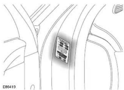
natural_image
Line drawing of a car interior showing a vehicle's seatbelt with no visible text or symbolsVehicles have the Certification Label adhered to the left-hand front door hinge post. Vehicle weights, paint code, manufacture date and the VIN are shown on this plate.
Engine number
Petrol engines:
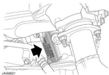
natural_image
Mechanical assembly diagram showing a piston-cranked cylinder inserted into a housing (no text or symbols visible)V8: The number is located on the rear left-hand side of the cylinder block, adjacent to the transmission flange, shown above.
V6: The number is located on the lower left-hand side of the cylinder block, near the bedplate.
Diesel engines:
The number is located on a metal label attached to the top of the left-hand camshaft cover.
Transmission number
On a metal label or bar code label attached to the transmission casing.
General Information
JAGUAR DIAGNOSTIC SYSTEM
Many of the vehicle systems are controlled by complex electronic devices. Specialist equipment is required to trace and rectify faults in the systems and ensure that only faulty components are repaired or renewed.
Caution: Severe damage to the electrical system and electronic components can occur if any attempt is made to diagnose faults in the electrical system using conventional diagnostic equipment (for example; the use of test lamps or low impedance voltmeters). The fitting of any electrical accessory should only be entrusted to a Jaguar Dealer/Authorised Repairer.
REGULAR SERVICING
Each vehicle is given a full Pre-Delivery Inspection to ensure that all systems function correctly and that the vehicle meets its specification.
Owners are responsible for the regular maintenance and servicing of the vehicle. Jaguar Dealers/Authorised Repairers will be pleased to arrange periodic servicing and can provide you with details of tasks carried out at each service interval.
Failure to implement maintenance at the recommended intervals could result in deterioration of vehicle performance and possible infringement of regulations.
Regular routine maintenance not only helps to prevent unnecessary breakdowns and inconvenience, but enhances the trade-in or resale value of the vehicle.
Failure to perform regular maintenance at the correct interval may void factory warranty.
RUNNING-IN
Apart from a few precautionary recommendations, there are no strict running-in procedures for this vehicle.
By observing the following advisory notes you will ensure maximum engine, transmission and brake life for your vehicle:
- Allow the engine to warm up thoroughly before operating at engine speeds over 3500 rev/min.
• Vary the speed frequently. - From 1500 kilometres (940 miles) onwards, gradually increase performance of the vehicle up to the permitted maximum speed, where road conditions permit.
Running in for brakes
To ensure that the brake pads can bed-in evenly and reach their optimum wear and performance condition, usually within 480 kilometres (300 miles), the following points are recommended:
- Where possible, avoid heavy braking or rough usage of the brakes as this can result in damage being caused to the brake pads and discs.
- Avoid prolonged use of the brakes, for example, when descending severe gradients.
- Frequent light application of the brakes is desirable. This helps to fully bed-in the brake pads before the normal running-in period is completed and the vehicle is operated at high speeds, when maximum brake efficiency will be required.
The above equally applies when new discs or pads have been fitted.
General Information
Warming Up
Do not operate the engine at high speed when first started, but allow time for the engine to warm up and the oil to circulate.
PROTECT THE ENVIRONMENT
We must all play our part in protecting the environment. Correct vehicle usage and disposal of waste cleaning and lubrication materials are significant steps towards this aim.
Avoid using high engine speeds. You will then protect your engine, reduce fuel consumption, lower the engine noise level and help towards reducing the environmental burden.
Care should be taken at all times to avoid polluting the environment. Used materials, for example, batteries, tyres, fluids and filters, should be disposed of at suitable facilities in accordance with local legislation. If in doubt, clarification should be sought from your local authority/regulator.
MOBILE/PORTABLE TELEPHONES
Check the laws and regulations on the use of cellular telephones in the areas where you drive. Always obey them. Also, give full attention to driving.
Use hands-free operation (if fitted) and pull off the road and park before making or answering a call, if driving conditions so require.
WINDOW TINTING
Do not have your vehicle windows tinted with a metal oxide tinting (for maximum heat reduction from sun load) if you have a navigation system fitted to your vehicle.
Metal oxide tinting prevents the reception of the Global Positioning Satellite (GPS) system signals by the antenna, causing the navigation system to stop functioning.
In addition, metal tinting must never be applied to windows that contain antenna patterns as radio reception will be degraded.
A non-metal tinting should be used if you require window tinting and if in doubt, contact your Jaguar Dealer/Authorised Repairer for advice.
FLOOR MAT RETENTION
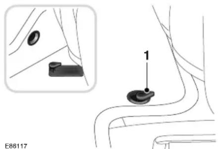
text_image
E86117Ensure that the driver floor mat is correctly positioned and secured under the tongue on the retention post (1), [only one shown], so that it does not interfere with the operation of the accelerator pedal or the brake pedal.
The positioning of the mat should be especially checked when refitted after removal for cleaning or servicing.
General Information
LEATHER CARE GUIDE
Leather is a natural product, therefore, it bears natural characteristics, such as grain variations, growth and brush marks. These non-weakening marks show the true nature of the hide and are the hallmarks of a leather product. Leather is an easy to maintain natural product, however, dust and substances can penetrate the pores and crease the leather, causing surface wear and brittleness.
To prevent ingrained dirt, inspect the seat upholstery regularly and clean every one to two months as follows:
- Wipe off fine dust from the seat surfaces at regular intervals using a clean, damp, non-coloured cloth. Change frequently to a clean area of cloth to avoid abrasive action on the leather surface. Avoid over-wetting.
- If this is not sufficient, use a cloth which has been dampened with warm soapy water and then wrung out; avoid over-wetting. Use only mild non-caustic soap.
- Use Jaguar Leather Cleaner for heavily soiled areas. Dry off and rub with a clean soft cloth, changing surfaces regularly.
- Sharp objects such as belts, zip fasteners, rivets, etc. can leave permanent scratches on the leather surface.
-
Dark clothing may stain leather seats just like other upholstery products.
-
Do not use solvents such as petrol (gasoline), white spirit or alcohol. Do not use detergents, furniture polish or household cleaners. Such strong treatments may give, initially, an impressive appearance, but their use will lead to rapid damage or deterioration of the natural properties of the leather. Jaguar recommend a basic set of products that have been specially selected for the type of leather in your vehicle. The Manufacturer's Warranty will be invalidated if treatments are used other than those recommended by Jaguar Cars Limited.
- Unless spillages such as tea, coffee or ink are washed away immediately, permanent staining may have to be accepted.
When staining (e.g. from clothing) or spillage occurs, clean the affected area immediately as described above.
It is recommended that Jaguar Leather Cleaner is used several times a year to maintain its appearance and suppleness. The Jaguar Leather Cleaner will nourish and moisturise the leather and help to improve and renew the surface protective film against dust and substances.
If a valet service is used, ensure that the specialist concerned is aware of, and follows, these instructions precisely.
For any further questions please consult your Jaguar Dealer/Authorised Repairer for specialist advice.
Data Recording
SERVICE DATA RECORDING
Service data recorders in your vehicle are capable of collecting and storing diagnostic information about your vehicle. This potentially includes information about the performance or status of various systems and modules in the vehicle, such as engine, throttle, steering or brake systems. In order to properly diagnose and service your vehicle, Jaguar Cars Limited and service and repair facilities may access vehicle diagnostic information through a direct connection to your vehicle when diagnosing or servicing your vehicle.
Other modules in your vehicle - event data recorders - are capable of collecting and storing data during a crash or near crash event. The recorded information may assist in the investigation of such an event. The modules may record information about both the vehicle and the occupants, potentially including information such as:
- How various systems in your vehicle were operating.
- Whether or not the driver and passenger seat belts were buckled.
- How far, if at all, the driver was depressing the accelerator and/or the brake pedal.
• How fast the vehicle was travelling. - Where the driver was positioning the steering wheel.
To access this information, special equipment must be directly connected to the recording modules. Jaguar Cars Limited do not access event data recorder information without obtaining consent, unless pursuant to court order or where required by law enforcement, other government authorities or other third parties acting with lawful authority.
Other parties may seek to access the information independently of Jaguar Cars Limited.
HEALTH AND SAFETY PRECAUTIONS

WARNING:
Many liquids and other substances used in vehicles are poisonous and should never be consumed and must be kept away from open wounds. These substances include antifreeze, brake fluid, fuel, windscreen washer additives, lubricants and various adhesives.

WARNING:
The presence of any unusual fumes (for example; petrol, diesel or exhaust fumes) in the passenger compartment and/or luggage compartment should be corrected immediately by a Jaguar Dealer/Authorised Repairer.

WARNING:
If you must drive under these conditions do so only with all windows fully open.

WARNING:
By operating other electronic equipment (for example; a mobile phone without an exterior antenna) electro-magnetic fields can cause malfunctions of the vehicle electronics. Therefore, you should observe the instructions of the equipment manufacturers.

WARNING:
Any modifications to the fuel system not specifically designed for this Jaguar are prohibited. Such modifications in some circumstances could result in a fire. All service actions must be entrusted to a Jaguar Dealer/Authorised Repairer.

WARNING:
Alterations to the electrical system, including the fitting of accessories not designed for this Jaguar, will cause damage to the electrical circuits and systems. In some circumstances this could result in a malfunction or fire. All accessory work should be entrusted to a Jaguar Dealer/Authorised Repairer.

WARNING:
No attempt should be made to repair a fuse that has blown. Always install a new fuse of the correct amperage. Failure to comply with the above may cause a fire hazard or create serious damage elsewhere in the electrical circuit.

WARNING:
Avoid contact with battery acid which is poisonous and corrosive. Acid will cause burns to the skin as well as to the eyes. In the event of skin or eye contamination, wash the affected area with water thoroughly. Seek immediate medical attention when eye contact has occurred.
Health and Safety

WARNING:
Do not disconnect any pipes in the air conditioning refrigeration system. A refrigerant is used which can cause blindness if allowed to contact the eyes. If refrigerant should contact the eyes or skin, wash the eyes or affected area with cold water for several minutes. Do not rub. As soon as possible thereafter, obtain treatment from a doctor or eye specialist.

WARNING:
When working within the engine compartment, take care to avoid contact with moving parts and hot components.
Ignition Switch
IGNITION SWITCH
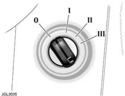
text_image
I II III 0 JOL3035The facia-mounted ignition switch, on the right-hand side of the steering column, has four key positions:
0 Ignition OFF - Is the only position in which the key can be inserted and removed.
I Auxiliary - allows use of some electrical circuits, for example, radio and window operation (accessory delay only).
II Ignition ON - All electrical circuits except the starter motor are activated. The key remains in this position when driving.
III Engine start - The starter motor is operated for as long as the key is held in this position, against spring pressure.
When the key is turned back to the OFF position, the delayed accessory feature (window operation etc.) becomes active.
The circuits available in the auxiliary position remain activated for a preset timed period or until a front door is opened.
To remove the ignition key
Automatic transmission vehicles have a key interlock feature.
Apply the Electric Parking Brake, move the gear selector to the Park P position and turn the key to position 0.
The automatic transmission gear selector must be placed in Park P before the key can be removed from the ignition switch.
When the key is removed, the gear selector will be locked in Park.
Steering column lock
The steering column lock is controlled by the ignition switch.
When the key is removed from the ignition switch, you will hear the steering column lock engage.
When the key is inserted into the ignition switch, you will hear the steering column lock disengage.
In rare circumstances, it may be necessary to gently turn the steering wheel from side to side to release the steering column lock.
Gearshift interlock
A brake pedal/gearshift interlock system is incorporated in the automatic transmission gear selector mechanism.
To move the gear selector from Park:
- Turn the ignition key to position II or start the engine.
- Press the brake pedal.
- Select a gear.
Vehicle Security
GENERAL INFORMATION
When the vehicle is unoccupied or unattended, you are advised to do the following:
- Apply the Electric Parking Brake and move the gear selector to the Park P position.
- Do not leave children or pets in the vehicle unattended.
- Do not leave luggage or valuables on display.
- Remove all keys, including remote transmitters, from the vehicle prior to locking the doors, even when the vehicle is in your garage.
- Close all windows, luggage compartment and glove compartment, and lock all the doors.
- Park the vehicle where it can be seen. At night, park in a well-lit area.
- It is important to keep your keys in safe places at all times. Leaving them in conspicuous places is an invitation for a thief to steal them and, consequently, your vehicle or belongings. Keep them as secure as you would your wallet or purse, both at home and away.
This vehicle is fitted with an immobilisation system. The system prevents the vehicle being driven away by unauthorised persons.
Note: The vehicle alarm and immobiliser are Thatcham category one approved, and meet European regulation 97 and directive 95/56/EC.
Programmable key
An electronic device is fitted in the head of each key which is programmed to the vehicle electronic systems.
When a programmed key is inserted into the ignition switch it is recognised and accepted by the vehicle's electronic systems.
The engine cannot be started with a key that is not programmed to the vehicle electronic systems.
Immobilisation system status light
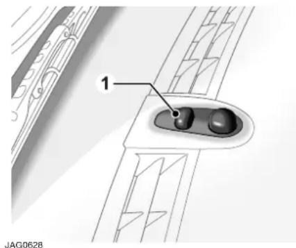
text_image
1 JAG0628The immobilisation system status is shown by a Light Emitting Diode (LED), which is located on the top surface of the facia panel (1).
If an ignition key is put into the ignition switch and turned to position II, and the LED remains flashing after three seconds, it is possible that the engine will not start.
Should this occur, please contact a Jaguar Dealer/Authorised Repairer, who will investigate the cause of the flashing LED.
Vehicle Security
KEYS
Vehicles are supplied with two integrated transmitter keys and one green-headed valet key. Additionally, black-headed keys are available and for further details, contact a Jaguar Dealer/Authorised Repairer.
Integrated key transmitter
The integrated transmitter key comprises the key body integrated with a remote transmitter. The key operates all the locks on your vehicle.
Green-headed valet key
The green-headed valet key is not integrated with a remote transmitter. The key operates the driver's door lock and the ignition switch, but does not operate the luggage compartment lock.
Black-headed key
This black-headed key is not integrated with a remote transmitter, but it does operate all the locks and the ignition switch on your vehicle. The key is not supplied with your vehicle. For further details, contact a Jaguar Dealer/Authorised Repairer.
Additional keys
Five additional keys can be programmed to operate the locks on your vehicle.
Note: A maximum of three additional integrated keys can be used.
All additional keys must be obtained from and programmed by, a Jaguar Dealer/Authorised Repairer.
Key number label
The key number is recorded on an adhesive label which is affixed to the rear of the integrated transmitter keys. Peel off the label and keep safely, not in the vehicle.
Vehicle Security
KEY TRANSMITTER

WARNING:
Never leave the key transmitter in the vehicle if children or animals are also left in the vehicle. The vehicle's systems and remote control functions could be operated, which may result in injury.

text_image
1 2 3 4 5 E86118- To release the key from the transmitter, press and release the release button. Press and hold the button and fold the key into the transmitter.
- Unlocks and disarms the vehicle.
- Releases the luggage compartment lock.
- Activates the convenience headlamp feature or sounds the panic alarm.
- Locks/double-locks and arms the vehicle.
The security system is controlled remotely by a radio frequency, battery-operated, integrated transmitter key.
The transmitter is activated by pressing one of the operating buttons.
Note:
- The key transmitter may not operate correctly in areas which are subject to interference from other radio equipment operating on the same frequency. Interference may emanate from sources such as amateur radio, medical equipment, telecommunications devices and other remote controls or alarms. Where such interference is experienced, operate the key transmitter as close as possible to the vehicle, or use the key in the driver's door lock.
- All buttons on the key transmitter will not operate if a key is in the ignition switch, however, if the doors, bonnet or luggage compartment are open, only the lock button will not operate.
Each integrated key will operate all the locks on your vehicle.
Additional integrated key transmitters can be obtained from your Jaguar Dealer/Authorised Repairer. See Additional keys on page 16.
Vehicle Security
Key transmitter battery renewal

text_image
1 2 3 4 E86124When the battery needs renewal there will be a significant decrease in the effective range of the key transmitter. To renew the battery:
- Insert a small, flat-blade, screwdriver at an angle of about 45 degrees, into the slot on the back of the key transmitter as shown (1). Apply light pressure to the screwdriver and lever the screwdriver forward to separate the two halves of the key transmitter. Finally, pull the transmitter from the key body.
- Insert the screwdriver into the slot between the transmitter covers adjacent to the key stowage area as shown (2). Apply light pressure to the screwdriver and lever the screwdriver downward to separate the covers.
- Unscrew and remove the small screw (3) and remove the printed circuit board, taking care not to touch the battery terminals. Remove the battery and dispose of it safely.
- Fit a new battery cell, type CR2032 (available from your Jaguar Dealer/Authorised Repairer), with the side marked with the positive symbol (+) downwards in the battery receptacle. Avoid touching the new battery as moisture/oil from the fingers can reduce the life of the battery and corrode the contacts.
- Replace the printed circuit board making sure to engage the board under the securing tabs (4), and secure with the screw.
- Refit the cover and click into place with thumb pressure.
- Slide the transmitter back onto the key body until it clicks into place.
Vehicle Security
Care of key transmitters
The key transmitters must be treated with care. Do not expose to extremes of heat, dust, humidity or fluids. Do not leave the transmitter exposed to direct sunlight. The battery is the only serviceable part.
Caution: Should a key transmitter be lost, a new one can be obtained and programmed to the vehicle by a Jaguar Dealer/Authorised Repairer, who will ask for proof of vehicle ownership. It is advisable to notify a Jaguar Dealer/Authorised Repairer as soon as a key transmitter is lost or stolen and have the remaining key transmitter(s) reprogrammed. This will then prevent the lost or stolen key transmitter from being used to disarm and unlock the vehicle.
Note: Jaguar Dealers/Authorised Repairers keep a log of all enquiries for replacement keys and notify Jaguar Cars Limited of any such requests.
RADIO FREQUENCY APPROVAL
If the type approval of your key transmitter requires inspection, refer to the table below:
Type Exam. Certificate Number: CERT 980154-01
Korean Market Certification Number: R-LPD1-02-00-0018
| Country Approval | No. |
| All EU and EFTA countries | CE 0700 ⚠ |
Caution: The key transmitter may suffer interference from other legal users of this radio frequency band, such as radio amateurs, medical equipment, remote controls or alarm systems. To lock or unlock the vehicle, either use a key or operate the transmitter as close to the security antenna on the rear screen as possible.
Door Locks
LOCK THE VEHICLE AND SET
THE ALARM
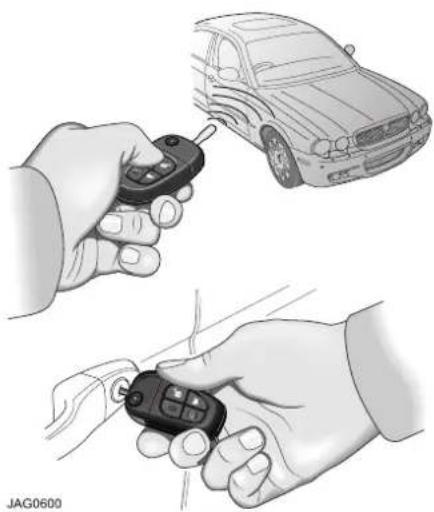
natural_image
Illustration of hands holding a car key and a car with sensor array (no text or symbols)All doors can be centrally locked and unlocked remotely, using the key transmitter buttons.
Only the driver's door is equipped with an external key lock, which activates the central locking, double-locking (when enabled), two-stage unlocking (when enabled) and central unlocking (when enabled).
- Ensure windows and sunroof (if fitted) are fully closed.
- Press the lock button on the key transmitter, or;
- Put the key in the driver's door lock, turn the key towards the rear of the vehicle and release.
The direction indicators will flash once, and the security light (located on the top surface of the facia) will start flashing. After 20 seconds, the alarm will be set.
If a door, the bonnet or the luggage compartment are open and an attempt is made to lock the vehicle, the direction indicators will flash five times (if enabled) and/or an audible warning will sound twice as a warning that the vehicle is not secure.
Note: The security system will not arm if a key is in the ignition switch. If a key is used in the driver's door key barrel and turned towards the front of the vehicle and released when an aperture is ajar, (2 error tones (if enabled), or five flashes of the direction indicators (if enabled) will be emitted). The security system will arm, but will not monitor the aperture that is ajar until it has been fully closed.
Double-locking

WARNING:
Never double-lock the vehicle with people, children, or pets inside. In the event of an emergency they would be unable to escape, and the emergency services would be unable to release them quickly.
Note: It will not be possible to double-lock the vehicle if any door is open, a key is in the ignition switch or the inertia switch has been tripped.
With all doors, luggage compartment, and bonnet closed, and no key in the ignition switch, press the lock button on the key transmitter twice within three seconds to double-lock the vehicle and set the alarm.
Alternatively, place the key in the driver's door lock, turn the key towards the front of the vehicle and then towards the rear within three seconds to set the alarm.
Door Locks
The exterior direction indicators will flash once as locking takes place and a longer, second flash as double-locking takes place. An audible tone will be produced to confirm that the vehicle has been double-locked.
Drive-away door locking
With the ignition key at position II and all the doors closed, all doors will lock when the gear selector is moved from position P (Park) or N (Neutral). The gear selector has to be moved from P or N, and into a different gear, for longer than one second.
If the vehicle is stopped and a door is opened and subsequently closed, the doors will lock again when the gear selector is moved from position P or N, and into a different gear.
If the vehicle is stopped and a door is opened and subsequently closed, but the gear selector is not moved from position P or N, or the current gear position, the doors will remain unlocked.
All vehicles have the drive-away door locking feature installed during manufacture, except Japan.
This feature can be disabled, or reinstated, by a Jaguar Dealer/Authorised Repairer, if required.
Central locking switch
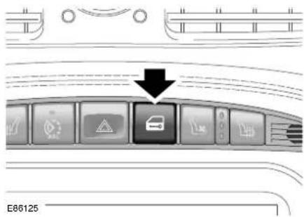
text_image
E86125The ignition switch must be in either position I or II for the central locking switch to operate.
With all the doors closed and unlocked, one press of the switch will lock all of the doors and inhibit the luggage compartment.
With all the doors closed and locked, one press of the switch will unlock all of the doors and allow access to the luggage compartment.
If the vehicle is unlocked, press and hold the switch for more than two seconds to centrally lock the vehicle and close all the windows and sunroof (if fitted).
Releasing the switch will halt the operation of the windows and sunroof (if fitted).
If the vehicle is locked, press and hold the switch for more than two seconds to unlock the vehicle and open all the windows and sunroof (if fitted). Releasing the switch will halt the operation of the windows and sunroof (if fitted).
Note: All windows must be taught to the vehicle for this function to operate, see To reset the window anti-trap system on page 78.
Door Locks
If the central locking switch is pressed when the ignition switch is not in position I or II, the security system's inclination and intrusion sensors (if fitted) will not operate for one arming period. The security LED in the facia will flash for five seconds to indicate that this has occurred.

WARNING:
Make sure that all occupants are kept clear of the windows and sunroof aperture (if fitted).

WARNING:
When an interior door release lever is pulled, the door will unlatch.
After using the central locking switch, it may be necessary to press the switch again or pull a front door interior release lever to unlock the vehicle.
Smart locking
This feature helps prevent locking the key in the vehicle.
If a front or rear door is open or ajar and an attempt is made to lock that door using the interior locking lever, the locking lever is prevented from moving to the locked position. No locking will be made.
If an attempt is made to lock the vehicle using a closed front door interior locking lever and any other door is open, all doors will centrally lock and then unlock.
If an attempt is made to lock the vehicle using a closed rear door interior locking lever and any other door is open, only that door will lock; all other doors remain unlocked.
If a door, the bonnet or the luggage compartment is open, the vehicle can only be locked from the outside by using a key in the driver's door lock.
Note: An audible and/or visual error warning will be given.
It will not be possible to lock the vehicle with a key transmitter if a door, the luggage compartment or the bonnet is open, or a key is left in the ignition.
Global closing

WARNING:
Ensure that no children, pets, or obstructions are in any open aperture before operating global closing. Safety mechanisms are in place to prevent serious injury, however, injuries can still occur.
Key in the driver's door - Turn and hold the key towards the rear of the vehicle, for more than 2 seconds duration, to close all the electrically operated windows and sunroof (if fitted). If the key is released, the global closing action stops immediately.
Key transmitter - Press and hold the lock button for longer than 2 seconds to close all the electrically operated windows and sunroof (if fitted – one shot operation). Pressing any button again while global closing is taking place will stop all movement.
Door Locks
UNLOCKING THE VEHICLE
Using a Key Transmitter
Press the unlock button on the key transmitter.
Single-stage unlocking
This unlocks all doors, the luggage compartment, the interior lamps turn on and the security LED stops flashing. The direction indicators will flash twice to indicate that the system is disarmed.
Two-stage unlocking
The first press of the unlock button:
- Unlocks the driver's door.
- Enables the luggage compartment to be opened using the exterior release button.
- Turns on the interior lamps.
This will also disarm the system if it was armed, the direction indicators will flash twice and the security LED stops flashing.
A second press is required to unlock all doors (Jaguar Dealer/Authorised Repairer programmable or key transmitter selectable).
Using a Key
Single-stage unlocking
Put the key in the driver's door lock, turn the key towards the front of the vehicle and release. This will:
- Unlock all doors.
- Enables the luggage compartment to be opened using the exterior release button.
- Turns on the interior lamps.
The direction indicators will flash twice and the security LED will stop flashing.
Two-stage unlocking
Put the key in the driver's door lock, turn the key towards the front of the vehicle and release. This will unlock the driver's door, the luggage compartment is un-inhibited, and turn on the interior lighting. This will also disarm the system if it was armed, the direction indicators will flash twice, and the security LED will stop flashing.
Turning the key towards the front of the vehicle a second time will unlock all the remaining doors.
Selecting single-stage or two-stage unlocking
The procedure for changing from single stage to two stage unlocking (if enabled), or vice versa, is as follows:
- Press and hold the lock and unlock buttons on the key transmitter simultaneously for four seconds.
Note:
- The direction indicators will flash twice to confirm the action.
- To revert to the previous condition, repeat the procedure described above.
- For operation of the two stage unlocking feature when the vehicle is equipped with a touch-screen, please refer to the touch-screen display handbook.
Door Locks
Global Opening
Key in the driver's door - Turn and hold the key towards the front of the vehicle, for more than two seconds duration, to open all the electrically operated windows and sunroof (if fitted). If the key is released, the global opening action stops immediately.
Key transmitter - Press and hold the unlock button for longer than two seconds to open all the electrically operated windows and sunroof (if fitted – one shot operation). Pressing any button again while global opening is taking place will stop all movement.
Auto-relocking
This feature automatically centrally locks and arms the vehicle (if security and auto-relock are enabled) if the vehicle has been unlocked with the key transmitter having been previously locked (double-locked) and the security system armed:
- and no door, bonnet or luggage compartment has been opened in the last 45 seconds after the remote unlock operation or,
- if the ignition remains off for 45 seconds after the remote unlock operation.
Note: This feature is disabled at the factory, but can be enabled or disabled, by a Jaguar Dealer/Authorised Repairer, as required.
Direction Indicator Unlock Alerts
The exterior direction indicators give two flashes as unlocking takes place.
Note:
- If a fault exists with the intrusion sensing or inclination sensing systems (if fitted), the exterior direction indicators will flash three times accompanied by one audible sound, or, the exterior direction indicators will flash three times accompanied by three audible sounds, or, the direction indicators will flash seven times, or, the direction indicators will flash seven times accompanied by one audible sound, or, the direction indicators will flash seven times accompanied by three audible sounds. You can choose either method of fault indication. For further information, contact your Jaguar Dealer/Authorised Repairer.
- If the audible method is enabled then the direction indicator method is disabled.
Door Locks
INTERNAL DOOR LOCKING AND UNLOCKING
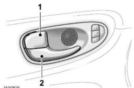
text_image
1 2 JAG0629To centrally lock all doors, press the lock lever (1) on the driver's or front passenger's door. Each rear door will lock/unlock and open independently by operating the door release levers.
To unlock a front or rear door, pull the release handle (2) or the lock lever (1).
The driver's or front passenger's door lock lever will unlock all doors.
Note: Operating the locks more than 15 times within 20 seconds will prevent the central locking from being used for 20 seconds. If required, the locks may be operated individually during the 20 second waiting period.
VALET KEY LOCKING
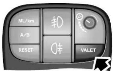
text_image
ML/km A/B RESET 转 0 VALET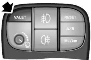
Before locking the vehicle and handing the green-headed valet key to a parking attendant, press the valet switch to inhibit the luggage compartment interior release switch, external luggage compartment switch, and the glove compartment switch. When the valet switch is pressed an audible valet mode chime will be emitted.
If the key is in ignition position II when the valet mode switch is pressed, the VALET MODE message will be displayed on the message centre.
The vehicle can then be parked by an attendant who can lock the vehicle after parking, but cannot open the luggage compartment or glove compartment.
Door Locks
The luggage compartment can then only be unlocked with the key transmitter. To cancel valet mode, operate the key transmitter unlock button, or, manually unlock the luggage compartment with the key transmitter using the luggage compartment release key lock.
When in valet mode, each operation of the interior luggage compartment release switch, exterior luggage compartment switch or the glove compartment switch, will result in a chime being emitted which indicates that valet mode has been selected. If the ignition is set to position II a message will appear on the message centre display indicating that an unauthorised attempt has been made to open the glove compartment or luggage compartment.
Note:
- Do not use the green-headed key for normal driving as the luggage compartment and glove compartment cannot be opened.
- If the vehicle alarm system is armed and the luggage compartment is opened using the key transmitter, the alarm will not sound. The system will be rearmed when the lid is closed, provided the vehicle has not been disarmed.
- Neither the luggage compartment lid release switch on the facia switchpack nor the lid release button will operate when the vehicle is armed, or in valet mode. An attempt to operate these switches whilst in valet mode will result in an audible warning chime.
- Operating the internal, external or remote luggage compartment switches more than 15 times within 20 seconds, or opening and closing the luggage compartment will cause opening to be inhibited for 20 seconds. Should this happen wait 20 seconds for normal operation to resume. If required, the luggage compartment may be opened by using the key during the 20 second waiting period.
Door Locks
CHILD SAFETY LOCKS

text_image
Instructional diagram showing a hand using a lock switch to adjust a card, with an icon indicating the lock function.E86300
Child safety locks are fitted to the rear doors.
Open a rear door, insert the ignition key into the lock and turn the key outwards. This immobilises that door interior handle Repeat this for the opposite rear door.
After setting the child lock, the door(s) can only be opened using the exterior door handle.
To remove the child lock feature, open the door and using a key, move the control to its original unlock position.
Luggage Compartment
LUGGAGE COMPARTMENT
LOCKS
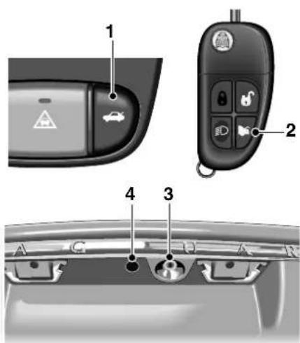
text_image
Diagram of car interior components with labeled parts including control panel, key keys, and rear camera viewE86128
The luggage compartment is locked and unlocked electrically in conjunction with the doors.
Neither the luggage compartment lid release switch on the facia nor the lid release button will operate whilst the vehicle is armed or in valet mode. An attempt to operate these switches whilst in valet mode will result in an audible warning chime.
To open the luggage compartment, use any of the methods that follow:
- Press the luggage compartment lid release switch (1), which is located on the facia switchpack. This switch will not operate if the vehicle speed exceeds 8 km/h (5 mph).
- Press the luggage compartment button (2) on the key transmitter (see the Note following).
Note: Button (2) will only operate with the gear selector in Park.
- Insert a key into the luggage compartment lock (3), however, opening with the key when the vehicle is armed will cause the alarm to sound immediately. Should this occur, press the transmitter unlock button, or place the key in the ignition, to disarm the alarm system.
- With the vehicle unlocked, press the release button (4) on the luggage compartment lid. The button will not operate unless Park or Neutral has been selected and the vehicle is unlocked.
- The luggage compartment locks automatically when the lid is closed.
Alarm Systems
AUDIBLE SIGNALS
Note: In certain countries, legislation prohibits the use of audible confirmation signals. In such cases, the sound source has been removed from the system.
Two audible signals will be heard (if enabled) if an attempt is made to lock the vehicle with a key in the driver's door lock barrel or the lock button is pressed on the key transmitter; if a door, the bonnet or the luggage compartment is not fully closed, or a key is in the ignition switch.
European countries only: If the vehicle is unlocked with a key, a ticking sound will be heard when the driver's door is opened.
This is a warning to indicate that the vehicle alarm will activate after seven seconds if the vehicle is actively armed, and after 15 seconds if the vehicle is passively armed.
The full alarm will activate, as previously described, unless the security system is disarmed, either by pressing the unlock button on the key transmitter, or by placing a valid key into the ignition switch and turning the key to position II.
Note:
- If a passenger door is opened before the driver's door, or during this period, before the vehicle is disarmed, the alarm will sound immediately.
- The security system is not disarmed when unlocking with the key. This feature gives additional protection against vehicle theft.
An audible signal will sound when:
- The vehicle is double-locked (when fitted and enabled).
- The valet switch is pressed with the luggage compartment closed.
- The vehicle is in valet mode and the interior/luggage compartment release button, or glove compartment switch is pressed.
- A door is opened if the vehicle has been actively armed (United Kingdom and Europe only). This mode can be cancelled by disarming the security system using the key transmitter, or by switching the ignition to position II.
- A door is opened if the vehicle is passively armed. This mode can be cancelled by disarming the security system, using the key transmitter, by turning the key in the ignition switch to position II, or, by turning the key in the driver's door lock barrel towards the front of the vehicle.
FULL ALARM
Once armed, any of the following circumstances will create a full alarm state, sound the horns, sound the siren, or a combination of both (as country legislation dictates) and flash the direction indicators:
- Opening a door, luggage compartment lid (except with transmitter) or bonnet.
- Movement in the passenger area (if intrusion sensors are fitted).
- Using a key in the ignition switch which is not programmed to the vehicle.
- An attempt to lift, or tow the vehicle (when inclination sensor fitted).
Alarm Systems
- The vehicle battery is disconnected and the vehicle is fitted with a Battery Backed Sounder (only Battery Backed Sounder will be audible).
- If, after 15 seconds (passively armed), from opening the driver's door with a key (as country legislation dictates), the key is not inserted into the ignition switch and turned to position II, or a passenger door is opened before the driver's door.
- If, after seven seconds (actively armed), from opening the driver door with a key (as regional legislation dictates) the key is not inserted into the ignition and turned to position II, or a passenger door is opened before the driver's door.
- Any attempt is made to remove the radio or the front navigation system (if fitted).
- Pressing the headlamp convenience button on the remote transmitter three times within three seconds activates the panic alarm (if enabled).
HEADLAMP CONVENIENCE
One press of the headlamp convenience button switches the headlamps on for 25 seconds, or until the headlamp convenience button is pressed for a second time, or until a valid key is inserted into the ignition switch.
ERROR AUDIBLE SIGNALS
Two audible signals will be heard whenever one of the following conditions are present:
- If any door is open when an attempt is made to lock the vehicle.
- The luggage compartment or the bonnet is not properly closed when an attempt is made to lock the vehicle.
- A key is present in the ignition switch and a button on the transmitter is pressed.
See Direction Indicator Unlock Alerts on page 24 for the Notes regarding error signals during failure of intrusion sensor (if fitted), and inclination sensor (if fitted).
Note: The error audible signal can be disabled and the direction indicator flash option can be enabled (and vice versa) by a Jaguar Dealer/Authorised Repairer.
ERROR FLASH SIGNALS
The direction indicators will flash five times whenever one of the following conditions are present:
- The luggage compartment or bonnet are not fully closed when an attempt is made to lock the vehicle.
- If any door is open when an attempt is made to lock the vehicle.
- A key is present in the ignition switch.
See Direction Indicator Unlock Alerts on page 24 for the Notes regarding error signals during failure of intrusion sensor (if fitted), and inclination sensor (if fitted).
Alarm Systems
SECURITY FEATURES
The security system has been designed for:
• Prevention of theft of the vehicle.
- Prevention of theft of items from the vehicle.
- Personal security.
The security system is integrated with the vehicle electronics and engine management systems making it far more difficult for a thief to penetrate and steal the vehicle.
Intrusion sensing
A further enhancement to the security system is the addition of intrusion sensing, (where fitted).
When the vehicle is armed, movement within the vehicle interior will activate the alarm, therefore do not lock people or animals in the vehicle, otherwise the alarm will sound when it senses movement.
The luggage compartment can be unlocked, using the key transmitter button, without sounding the alarm.
When the security system is disarmed the intrusion sensors are also disarmed.
Note: If the vehicle has double-locking disabled, then the intrusion sensor is active upon centrally locking using the key transmitter or the key in the driver's door.
Inclination (tilt) sensing
This feature, (if fitted) protects against unauthorised towing away or jacking up. When the vehicle is double-locked and armed, any tilting of the vehicle, such as jacking or lifting, will activate the alarm.
Note:
- If the vehicle is being transported by road, rail or sea, press the central locking switch, located on the facia panel, prior to locking the vehicle. This prevents the intrusion and the inclination system from being armed for one alarm cycle, and sounding the alarm as the vehicle pitches and rolls.
- If the vehicle has double-locking disabled, the inclination sensor is active when the vehicle has been locked using the key transmitter, or using the key in the driver's door lock.
Panic alarm
When in or near the vehicle, the alarm can be set off to deter a possible offender. For this feature to operate, the key must not be in the ignition switch.
Pressing the headlamp convenience/panic button on the key transmitter three times within three seconds will activate the panic alarm.
The alarm is stopped by putting the key into the ignition switch and turning to position II.
Note:
- The key transmitter cannot be used to cancel the panic alarm. This prevents unauthorised cancellation in an emergency.
- The panic alarm is normally disabled. If required, this feature can be enabled or disabled by a Jaguar Dealer/Authorised Repairer.
- The vehicle locking status will not change when the panic alarm is activated.
Alarm Systems
Passive arming
Caution: Passive arming will not lock the doors, it only arms the security alarm system.
Passive arming, if enabled by a Jaguar Dealer/Authorised Repairer, will automatically arm the vehicle alarm system 30 seconds after the last protected entry (door, luggage compartment) is closed following the key being removed from the ignition switch.
When passive arming occurs, the direction indicators will flash once and a single tone will be heard (when enabled). The red security light on the facia will start to flash and will continue for as long as the alarm is armed.
Opening the driver's door causes a warning sound which continues for 15 seconds before the system goes into the full alarm state. If any other door is opened before the driver's door, the system goes into the full alarm state immediately.
When the system is passively armed and a black-headed, or integrated key is used to open the boot, full alarm is activated.
Note: Some non-European vehicles will emit a seven second warning signal followed by full alarm.
If the system has been passively armed it can be disarmed by either using the key transmitter, by switching the ignition to position II, or by unlocking the driver's door with the key.
Note: The security system will not passively arm if a key is in the ignition switch or if any protected entry is open.
Battery reconnection
If the battery has been disconnected and is subsequently reconnected, the alarm system will resume the same state as before the battery was disconnected.
If the alarm was sounding when the battery was disconnected, it will sound again when the battery is reconnected if the trigger that caused the alarm is still active (a door ajar, for example) and to disarm the vehicle will need:
- The transmitter unlock button to be pressed, or
- A key placed in the ignition switch and turned to position II, or
- The driver's door to be unlocked with a key.
If the trigger is no longer active (the door is now fully closed) the alarm will not sound.
Battery-backed sounder
In certain markets a separate, self-contained, battery-backed sounder is fitted. This device will sound the full alarm if the vehicle alarm is activated, or if the vehicle battery or the sounder is disconnected when the security system is armed.
Garage Door Opener
INTRODUCTION

natural_image
Front view of a device control panel with buttons and indicator lights (no text or symbols visible)The garage door opener transceiver is located in the overhead console. The transceiver can be programmed to transmit the radio frequencies of up to three different transmitters used to activate garage doors, entry gates, home lighting, security systems, or other radio frequency operated devices.
Although this section mainly describes the procedures for the garage door opener, it also equally applies to the previously mentioned applications. In some countries this feature is also known as HomeLink® Universal Transceiver.

WARNING:
Do not use the transceiver with any garage door opener that lacks the safety stop and reverse feature as required by safety standards. A garage door opener which cannot detect an object, signalling the door to stop and reverse, does not meet current safety standards. Using a garage door opener without these features increases risk of serious injury or death.

WARNING:
When programming the transceiver to a garage door opener or entry gate, make sure that people, the vehicle and objects are out of the way to prevent potential harm or damage as the gate or garage door will activate during the programme.
Note: This device may suffer from interference if operated in the vicinity of a mobile or fixed station transmitter. This interference is likely to affect the hand-held transmitter as well as the in-car transceiver.
For information, or for assistance, contact your Jaguar Dealer/Authorised Repairer or the supplier by phone or via the internet (see page 36).
Garage Door Opener
BEFORE PROGRAMMING
Caution: When programming a garage door opener or entry gate that may require you to press and re-press the hand-held transmitter (cycle), unplug the device during the cycling process to prevent possible motor failure.
It is recommended that for best results, fit a new battery to the hand-held transmitter of the garage door opener (or other device) before programming. If your garage door opener receiver (located in the garage) is equipped with an antenna, ensure that the antenna is hanging straight down.
TO ERASE ALL PROGRAMMING
For first time programming, ensure that the engine is switched off:
- Turn the ignition switch to position I.
- Press and hold the two outer buttons on the garage door opener in the overhead console. Keep the buttons pressed, the indicator light will illuminate. The indicator light is part of the middle button in the garage door opener in the overhead console.
- Release the buttons when the lights begin to flash (this will take approximately 20 seconds).
All memories in the garage door opener have now been cleared.
Note: Do not perform this procedure when programming the additional garage door opener buttons.
PROGRAMMING THE VEHICLE
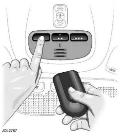
natural_image
Illustration of hands interacting with a device inside a vehicle (no text or symbols visible)Ensuring that the engine is switched off:
- Turn the ignition switch to position I.
- Hold the end of the original garage door opener hand-held transmitter approximately 50 mm to 150 mm (2 to 6 inches) away from the transceiver in the overhead console, keeping the indicator light in view.
- Using both hands, simultaneously press and hold both the desired garage door opener button on the overhead console and the hand-held transmitter button. Keep both buttons pressed. The light will flash, slowly at first and then change to a fast flash. When the indicator light flashes rapidly, release both buttons. The rapid flashing light indicates successful programming.
Garage Door Opener
- If, after 60 seconds, the indicator light does not flash rapidly, release both the transceiver and the hand-held transmitter buttons and repeat the procedure starting with Step 2. However, position the hand-held transmitter at a different angle and/or distance.
- Press and hold the programmed overhead console garage door opener button and observe the indicator light:
- If the indicator light is solid/continuous, programming is complete. Your device should activate when the garage door opener button is pressed and held for one to two seconds and then released.
- If the indicator light blinks rapidly for two seconds and then turns a solid/continuous light, proceed with the following programming instructions for rolling code device equipment.
Note: To programme additional garage door opener buttons, begin at Step 2.
Rolling code device equipment programming
Note: A second person may make the following steps quicker and easier as once the button has been pressed there are 30 seconds only in which to complete Step 3.
- At the garage door opener receiver (motor head unit) in the garage, locate the learn or smart button/switch. The name of the button/switch may vary between manufacturers.
-
Press and release the learn or smart button.
-
Return to the vehicle and firmly press and hold the programmed garage door opener button for two seconds and release.
- Repeat the press/hold/release sequence three times to complete the learning/training process.
The garage door opener in the overhead console should now activate the rolling code device.
Reprogramming a single garage door opener button
To programme a device to a previously trained button:
- Press and hold the desired pre-programmed garage door opener button for at least 20 seconds, but no longer than 30 seconds, until the indicator light begins to flash.
- Without releasing the overhead console button, position the hand-held transmitter approximately 50 mm to 150 mm (2 to 6 inches) away from the transceiver in the overhead console, keeping the indicator light in view.
- Carry out Step 3 of programming the vehicle, see page 34.
Entry gate programming
The technology of some entry gates requires you to press and re-press (cycle) the hand-held transmitter every two seconds during programming.
Continue to press and hold the desired overhead console button while you cycle your hand-held transmitter until the indicator light flashes rapidly.
Garage Door Opener
INFORMATION AND ASSISTANCE
For information on the range of available compatible products or accessories, or for assistance, contact your Jaguar Dealer/Authorised Repairer.
You can also contact the supplier's helpline on 0-0800-0466-354-65.
This toll-free number can be called from anywhere within Europe. No separate country code is required. (The first zero is not required when calling from within Germany.) If you experience difficulty using this number, then you may use the alternative number 0049 6838 907227.
Contact can also be made via the internet. The website address is www.eurohomelink.com. The e-mail address is info@eurohomelink.com.
Note: Keep the original transmitter for future use or programming procedures if, for example, you purchase a new vehicle.
Caution: It is recommended that when you sell or dispose of the vehicle, the programmed transceiver buttons be erased for security purposes.

WARNING:
The manufacturer is not responsible for any radio or TV interference caused by unauthorised modifications to this equipment. Such modifications could void the user's authority to operate the equipment.
Radio Frequency Approvals
APPROVALS FOR REMOTE RECEIVER 315 MHz
| Country Approval Number Country Approval Number | ||
| BR | PA | |
| BRN | PY | |
| BS | RA | |
| CDN | 3034A-RXSNOOK | RC |
| CL | RCH | |
| DOM | RI | |
| ET | RL | |
| HK | ROK | |
| J | No number required. | RP |
| JOR | SGP | |
| KSA | SYR | |
| KWT | T | |
| MA | UAE | |
| MAL | USA | |
| MEX | VN | |
| OM | VRC | |
USA covering Guam and Puerto Rico.
Radio Frequency Approvals
APPROVALS FOR REMOTE RECEIVER 433.92MHz
| Country Approval | Number | ||||||||
 |  |  |  |  |  | [HXY] |  |  | CE |
 |  |  |  |  |  |  |  |  | |
 |  |  |  |  |  |  |  |  | |
| Country Approval Number Country Approval Number | |||
 | TA Exempt | LT | |
| CZ | [30WT] | LV | |
 | No number required. | M | |
| UA |  | MD | |
 | QA | ||
 | RU | ||
 | SK | ||
| - | - | ZA | |
France covering French Guyana, Guadeloupe, Martinique, New Caledonia and Reunion.
Radio Frequency Approvals
APPROVAL NUMBERS FOR RADIO TRANSCEIVER
(EuroHomeLink 2000)
| Country Approval No. | |
| Austria GZ104569-ZB/98 | |
| Belgium RTT/D/X2064 | |
| Cyprus MCW129/95 12/2000 | |
| Czech Republic CTU 2000 3 R 1194 | |
| Denmark 98.3142-266 | |
| Finland FI98080106 | |
| France 97619 RD | |
| Germany D800038K | |
| Gibraltar RTTE20754/0087847 | |
| Greece JCI 05JUL2000 RTTE * | |
| Hungary BB-5793-1/2000 | |
| Iceland IS-3418-00 | |
| Ireland TRA 24/5/109/5 | |
| Italy DGPGF/4/341032/TB 0002573 | |
| Jordania TRC/LPD/2002/20 | |
| Kuwait 14JAN2002 | |
| Luxembourg L2433/10510-03J | |
| Malta WT/122/98 | |
| Netherlands | NL99030970 |
| Norway | NO20000026 |
| Poland | URT-GP-CLBT-431-66/2002/C |
| Portugal JCI03JUL2000RTTE | |
| Reunion, Martinique etc. | 97619 RD |
| Saudi Arabia | SAP20554184 |
| Slovak Republic | Not supplied |
| Spain | 0416 00 |
| Sweden ue990195 | |
| Switzerland | BAKOM 98.0746.K.P |
| Turkey | 0425/TGM-TR/JOCO-EURO |
| UA Emirates | K8133510-CC |
| United Kingdom | RTTE-3-59 / 20754 |
Occupant Protection
SEAT BELTS

WARNING:
Seat belts are designed to bear upon the bony structure of the body, and should be worn low across the front of the pelvis or the pelvis, chest and shoulders, as applicable; wearing the lap section of the belt across the abdominal area must be avoided.

WARNING:
Seat belts should be adjusted as firmly as possible, consistent with comfort, to provide the protection for which they have been designed. A slack belt will greatly reduce the protection afforded to the wearer.

WARNING:
Care should be taken to avoid contamination of the webbing with polishes, oils and chemicals, and particularly battery acid. Cleaning may safely be carried out using mild soap and water.

WARNING:
The belt should be replaced if webbing becomes frayed, contaminated or damaged.

WARNING:
It is essential to replace the entire assembly after it has been worn in a severe impact even if damage to the assembly is not obvious.

WARNING:
Belts should not be worn with the straps twisted.

WARNING:
Do not carry hard, fragile, or sharp items between your person and the seat belt. In an impact the pressure from the seat belt on such items can cause them to break, which in turn may cause death or serious injuries.

WARNING:
Each belt assembly must only be used by one occupant; it is dangerous to put a belt around a child being carried on the occupant's lap.

WARNING:
The occupants of the front seats should not travel with the seat back at more than 30 degrees from upright. Doing so will reduce the protection afforded by the seat belt.
Seat belt safety
The use of front and rear seat belts is mandatory in most countries. Using seat belts saves lives. They should be worn by all occupants, whenever the vehicle is in use, for maximum protection.
Lap/shoulder inertia reel seat belts are provided for both front occupants and three rear seat positions.
Occupant Protection
The inertia operating mechanism of the seat belts allows the wearers to move their upper bodies to reach various controls. The seat belts lock automatically with accelerated body movement or in the event of emergency braking.
The seat belt assemblies incorporate additional safety devices. All have belt pretensioners and the front belts also have force limiters. These devices provide increased protection in the event of a severe frontal impact.
The pretensioners operate with the airbags as part of the Advanced Restraints Technology System (ARTS).
See RESTRAINTS SYSTEMS on page 46.
Comfort belts are fitted to both individual electrically operated rear seats. They are also fitted to the outer seats only on the electrically operated rear bench seat. These belts incorporate a twin tension facility. When the belt is buckled around the occupant, a reduced tension is applied to provide a more comfortable fitting. When the belt is unfastened, a higher tension is applied to allow it to retract correctly.

WARNING:
Seat belts should be worn by all vehicle occupants, for every journey no matter how short. Failure to do so will greatly increase the risk of death or serious injury in the event of an accident.

WARNING:
No modifications or additions should be made by the user which will either prevent the seat belt adjusting devices from operating to remove slack, or prevent the seat belt assembly from being adjusted to remove slack.
A slack seat belt offers a greatly reduced level of occupant protection in an impact.

WARNING:
If any damage, wear, cuts, defects, or impaired operation are noted with the seat belts, the vehicle should be taken to a Jaguar Dealer/Authorised repairer for immediate attention. Do not use the vehicle if the seat belts cannot be operated correctly.

WARNING:
When using seat belts to restrain items other than occupants, take care to ensure that the belts are not damaged, or exposed to sharp edges.

WARNING:
Care must be taken to avoid contaminating the seat belt webbing, and seat belt mechanisms with any chemicals, liquids, grit, dirt, or cleaning products. If the seat belts do become contaminated they should be replaced immediately. Contaminated seat belts may not operate correctly in an impact and cannot be relied upon.
Occupant Protection
Seat belt checks
Note: If the vehicle is parked on an incline, the seat belt mechanism may lock. This is not a fault, and the belt should be gently eased out from the upper anchorage.
The seat belts should be inspected regularly to check for fraying, cuts, or wear to the webbing, and the condition and security of the mechanism, buckles, adjusters, and mounting points.
Checks
- With the seat belt fastened, give the webbing near the buckle a quick upward pull. The buckle must remain securely locked.
- With the seat belt unfastened, unreel the seat belt to the limit of its travel. Check that it unreels smoothly with no snatches or snags. Allow the belt to fully retract, again checking for smooth operation.
- Partially unreel the seat belt, then hold the tongue plate and give a quick forward pull. The mechanism must lock and prevent any further unreeling.
If any of the seat belts fail to meet those criteria, immediately contact you Jaguar Dealer/Authorised Repairer.
Beltminder
The Beltminder feature is a supplemental warning to the seat belt warning function, see page 91. This feature provides additional reminders to the driver that the driver's and/or front passenger's seat belt is unbuckled by intermittently sounding a chime and illuminating the seat belt warning indicator in the instrument panel.
Note: Not all countries have the warning chime.
Note: Objects placed on the front passenger seat may activate the seat belt reminder warning chime and indicator. It is recommended that any objects placed on the front passenger seat are secured using the seat belt.
Occupant Protection
Seat Belt Fitting

natural_image
Medical illustration showing a person seated in a car seat with a hand holding a car seatbelt above, no text or symbols present.A warning indicator on the instrument panel is illuminated when the driver's seat belt is not fastened. (In some countries a warning signal sounds for six seconds).
Note: If the vehicle is parked on unlevel ground, the seat belt mechanism may lock. This is not a fault, allow the seat belt to retract a small amount before gently easing the belt from its attachment to unlock it.
To release the seat belt, press the red button.
Note: When releasing the seat belt it is advisable to hold the belt before pressing the release button. This will prevent the belt from retracting too quickly.

WARNING:
Do not adjust the seat belt while driving.
Draw the tongue of the seat belt over the shoulder, across the chest and push it into the buckle unit slot. A positive 'click' indicates that it is safely locked.
Comfort clips or devices that create slack in the seat belts are not recommended.
Ensure that the webbing is midway between the neck and the edge of the shoulder. Correct tension is controlled by automatic retraction of the reel.
Occupant Protection
Front belt height adjustment
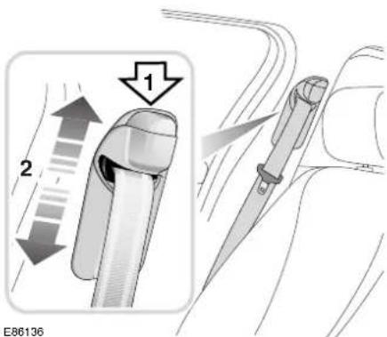
text_image
1 2 E86136
WARNING:
Correct seat belt adjustment is essential for safety and comfort. Ensure that the height is correctly adjusted and the mechanism is locked in place before driving the vehicle. Do not attempt to adjust the seat belt height once the vehicle is in motion. Doing so may cause you to loose control of the vehicle, or incorrectly adjust the seat belt.
To adjust the front seat belt heights, press the locking button (1) and slide the anchorage (2) so that the seat belt webbing passes over the shoulder without pulling against the neck. Release the button and check that the anchorage point is locked.
Always check the anchorage point after the seat has been adjusted to ensure that the belt is correctly positioned.
Seat Belt Clip
A clip is fitted to the seat belt for easier access to the tongue. This clip prevents the tongue from sliding down the seat belt to the side of the seat when the belt is undone, retaining it higher up the belt nearer to the shoulder.

natural_image
Technical diagram of a mechanical component with a black arrow indicating direction (no text or symbols present)JAG0630
It is important that when the belt is fitted around the lap and over the shoulder that any slackness (as shown in the next column) in the portion of belt over the lap is removed.
Occupant Protection
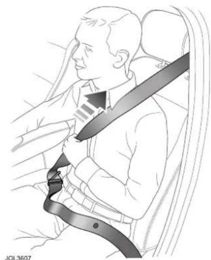
natural_image
Medical illustration showing a person seated with a car seatbelt and arrow indicating pressure or pressure (no text or symbols)If the belt has any slack in the lap strap this must be removed by pulling firmly upwards on the shoulder strap of the seat belt thus tightening the belt and safely securing the occupant.

WARNING:
Do not use the belt clip to introduce slack into the seat belt. To be fully effective, the seat belt must remain in full contact with the body at all times.
Pregnant Women

natural_image
Illustration of a pregnant woman sitting with a bandage, showing two different positions (no text or symbols present)
WARNING:
Position the seat belt correctly for the safety of the mother and unborn child. Never wear just the lap strap, and never sit on the lap strap whilst using just the shoulder strap. Both of these actions are extremely dangerous, and may increase your risk of serious injury in the event of an accident or during emergency braking.

WARNING:
Never place anything between you and the seat belt in an attempt to cushion the impact in the event of an accident. It can be dangerous, and will reduce the effectiveness of the seat belt in preventing injury.
Position the lap strap comfortably across the hips beneath the abdomen. Place the diagonal part of the seat belt between the breasts and to the side of the abdomen. Ensure that the seat belt is not slack or twisted.
Occupant Protection
RESTRAINTS SYSTEMS
Advanced Restraints Technology System (ARTS)

text_image
1 2 3 4 JAG0631JAG0631
In order to provide optimum protection this vehicle is equipped with front, side and curtain airbags. They are used in conjunction with the seat belts to help protect occupants from upper body (thorax) and head injuries.
-
The driver front airbag is located in the centre of the steering wheel.
-
The front passenger airbag is located in the facia panel immediately in front of the passenger seat.
- Curtain airbags are fitted on each side, above the front and rear doors.
- Thorax and pelvis side airbags are fitted within the outboard bolsters of both front seats, and are identified by labels.
Occupant Protection

WARNING:
High speed impacts may cause serious injury or death irrespective of safety features fitted to a vehicle. Always drive with caution and consideration for the vehicle's characteristics, road and weather conditions, and do not exceed any speed limits in force.

WARNING:
Seat belts should be worn at all times, by the driver and passengers in all seating positions. The airbag SRS cannot provide protection in some types of impact. Under these circumstances the only protection will be provided by a correctly worn seat belt.

WARNING:
Airbags inflate at high speeds, and can cause injuries. To minimise the risk of injury, ensure that all vehicle occupants wear correctly positioned seat belts, sit correctly in the seats, and position the seats as far back as practical.

WARNING:
Ensure that a gap is maintained between the side of the vehicle, and the head and torso. This will enable unobstructed inflation of the curtain, and seat mounted side airbags.

WARNING:
Airbag inflation takes place instantaneously, and cannot protect against the effects of secondary impacts. Under these circumstances the only protection will be provided by a correctly worn seat belt.

WARNING:
Phone systems should only be installed by qualified persons familiar with the operation of, and requirements for, vehicles fitted with SRS. If you are in any doubt, seek advice from your Jaguar Dealer/Authorised repairer.
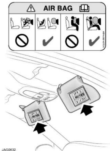
text_image
AIR BAG JAG0632Airbag warning information is printed on the driver's and passenger's sun visor.
Occupant Protection
The airbags and seat belt pretensioners are electrically controlled by an advanced restraints technology system.
Both front airbags use a dual inflation technology. When activated, the bag(s) will deploy at either a normal or reduced level of inflation, depending on crash severity. The lower inflation level is also selected if the restraint system senses that the seat occupant is too close to the airbag.
Various sensors determine the direction and severity of an impact and the presence and position of front seat occupants.
The system analyses this information then deploys the appropriate airbags only e.g. the side airbags where the impact is on that side only.
Airbags are not deployed in a rear impact.

WARNING:
For the airbags to operate correctly the roof lining and door post trims must be in good condition, correctly fitted, and free from obstruction. Any damage, wear, or incorrect fitment should be referred to your Jaguar Dealer/Authorised repairer as soon as possible for examination and repair.

WARNING:
Do not allow passengers to obstruct the operation of the airbags by placing any part of their person, or any objects, in contact with, or close to, an airbag module. Airbags deploy at very high speeds, and can cause serious injury or death if objects or occupants are within the area of deployment.
Disability modifications
Occupants with disabilities that may require the vehicle to be modified, must contact a Jaguar Dealer/Authorised Repairer before any modifications are made.
Airbag fault warning indicator

The airbag warning indicator in the driver's instrument panel will be lit for approximately six seconds when the ignition is turned on.
If the indicator remains on or flashes, it indicates a fault within the airbag electrical circuits. Report the fault to a Jaguar Dealer/Authorised Repairer immediately. It is safe to drive the vehicle; however, in an accident the airbags may not operate.

WARNING:
If the warning indicator signals that a fault is present in the system, do not use a child restraint on the front passenger seat. Doing so will increase the risk of death or serious injury to the child.
Airbag warning indicator information is shown on page 93.
Airbag deployment
To do their life-saving job, airbags must inflate rapidly and with considerable force. There is therefore a risk of death or serious injuries such as fractures, facial and eye injuries or internal injuries, particularly to occupants who are not properly restrained by seat belts or sitting correctly when the airbag deploys.
Occupant Protection
The risk of injury from a deploying airbag is greatest close to the trim covering the airbag.
The whole sequence of events from sensing the impact to full inflation of the bag takes place in a fraction of a second.
The noise and gas associated with the deployment of the airbags is not injurious to health.
After airbag deployment, it is normal to notice a smoke-like, powdery residue or smell the burnt propellant. This may consist of cornstarch, talcum powder or sodium compounds that result from the combustion process that inflates the airbag.
Small amounts of other chemicals may be present which may irritate the skin and eyes, but none of the residue is toxic.
While the system is designed to help reduce serious injuries, it may also cause minor burns, abrasions, swelling or temporary hearing loss.

WARNING:
No objects whatsoever should be attached to the centre cover of the steering wheel, the passenger facia panel, the sides of the front seats or the interior trim immediately above the door openings. Do not put anything on or over the airbag inflation area.
Placing objects on or over the airbag inflation area may cause those objects to be propelled by the airbag into your face and torso causing serious injury.

WARNING:
Safety experts recommend a minimum distance of at least
254 mm (10 inches) between an occupant's chest and a front airbag.

WARNING:
Children 12 years old and younger can be killed or seriously injured by the airbag. The rear seat is the safest place for children.

WARNING:
Do not try to put an adult seat belt around two children.

WARNING:
Several airbag system components get hot after inflation. Do not touch them after they have deployed.

WARNING:
If an airbag is inflated, the airbag will not function again and must be renewed immediately. If a new airbag is not fitted, the unrepaired area will increase the risk of injury in a collision.
Occupant Protection
Airbag deployment effects

WARNING:
When an airbag inflates a fine powder is released. This is normal, and not an indication of a malfunction. However, the powder may cause irritation to the skin, and should be thoroughly flushed from eyes, and any cuts or abrasions.

WARNING:
After inflation some airbag components are at high temperatures. To prevent injury, do no touch the airbag components until they have cooled.

WARNING:
In order to react with sufficient speed, airbags are deployed by an explosive charge. Consequently airbag deployment is accompanied by a very loud noise which may cause discomfort and temporary loss of hearing.
Front protection
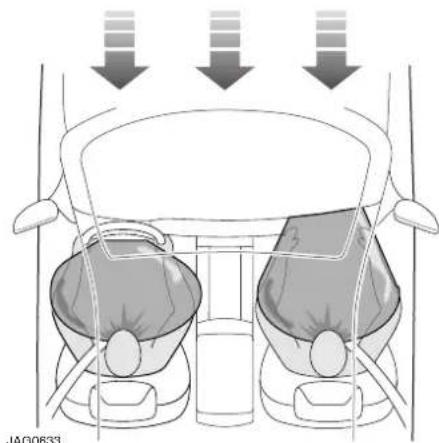
natural_image
Top-down view of a car interior showing two seats with directional arrows indicating movement or force (no text or symbols)With a front impact of sufficient force, the restraints system will trigger the front airbag(s) and seat belt pretensioners, which immediately tighten the seat belts.
For front occupants, the seat belt then slackens with increasing chest load, allowing the head and chest to more gradually come into contact with the inflated airbag. The airbag absorbs the remaining energy of the impact and then deflates rapidly via vent holes.
Front airbags are designed to inflate in frontal and near-frontal collisions, not low speed impacts, roll-over, side impact or rear impact.
Occupant Protection
Side protection

natural_image
Line drawing of a car driver inside a car, showing steering wheel and dashboard (no text or symbols)JOL3287
The airbags, in combination with the seat belts, can help reduce the risk of severe injuries in the event of a significant side impact collision.
The side protection system utilizes four airbags: Two mounted in the front seats, and two curtain airbags located just above the front and rear door openings, under the headlining trim.
When the seat mounted thorax airbag inflates upon a vehicle side impact, it breaks through the seat bolster stitching, protecting the side of the rib cage of the driver or front seat passenger.
When the curtain airbag inflates upon a vehicle side impact, it breaks through the headlining and deploys downwards, giving head protection to the front and rear seat occupants on the impact side.
The curtain airbag on the front passenger side is always deployed in a side impact even if the front passenger airbags are de-activated. This is to maintain protection for a rear occupant.
Seat mounted thorax and curtain airbags are designed to inflate in a side impact collision, not roll-over, rear impact, frontal or near-frontal collisions, unless the collision causes sufficient lateral deceleration.
Occupant Protection
Rear impact protection
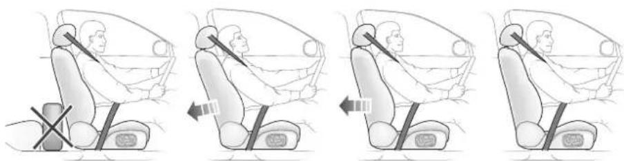
natural_image
Four-panel illustration showing a person seated in a car seat with arrows indicating left and right motion (no text or symbols)JAG0634
Both front seats have active, energy absorbent backrests which, with correctly positioned head restraints, reduce the risk of neck and spinal injury (whiplash) in the event of a rear impact.
When activated, the seat backrests automatically move back and recline, altering the occupants' posture and reducing relative motion between the body and head.
The degree of backrest movement in a rear collision depends on the angle, speed and nature of the colliding vehicle.
After activation, the whiplash protection mechanism will not work again and the seat must be serviced by a Jaguar Dealer/Authorised Repairer to restore the protective function.
Note: The amount of backrest movement depends on the severity of the impact and for a minor collision there may be no apparent change to the seat, even where the protective system has been activated.
After any rear collision, therefore, the seat must always be inspected by a Jaguar Dealer/Authorised Repairer.
WARNING:
For optimum protection, the driver and passenger should sit in the centre of the seat with the head as close as possible to the head restraint.
WARNING:
Adjust the head restraint so that it is just behind your head and never behind your neck.
WARNING:
Do not wedge objects (e.g. luggage) between the front seat backrest and the rear seat cushion.
WARNING:
After a rear collision, the front seats must be inspected by a Jaguar Dealer/Authorised Repairer even where there is no apparent damage or change to the seat.
WARNING:
Do not attempt to service or tamper with the seat recliner mechanism.
Occupant Protection
Occupancy sensing

text_image
Diagram of car interior showing dashboard, steering wheel, and air vent with directional arrows indicating movement or flow.The front passenger seat is monitored by ultra-sonic sensors (shown above) and a seat weight sensor to determine the presence, weight and position of the front passenger. In certain conditions, e.g. where no passenger is present, the appropriate airbags will be de-activated. In a collision these airbags would not be deployed.
Note: The occupancy sensing system is designed to confirm that a front passenger is properly seated as recommended:
• Always sit centrally in the seat, remaining in contact with the seat back which for comfort should be rearwards of the vertical position.
- Adjust the seat to be as far back from the facia as is practical.
• Always wear seatbelts.
The seat adjustment controls are described on page 68.
WARNING:
It is important that the passenger position sensors (see illustration) are not obscured in any way which could affect airbag deployment, e.g. fitting non-approved accessories.
WARNING:
Crash test data and statistics, show that the safest place for a child to be restrained, is in a child seat correctly fitted to the vehicle's rear seat.
WARNING:
Do not use a child restraint on a seat protected by an operational airbag in front of it. Doing so presents a high risk of death or serious injury to the child in the event of an accident.
WARNING:
Do not fit a child restraint to the front passenger seat if the SRS warning indicator illuminates continuously with the ignition on.
Occupant Protection
Airbag deactivation warning indicator (Yellow)
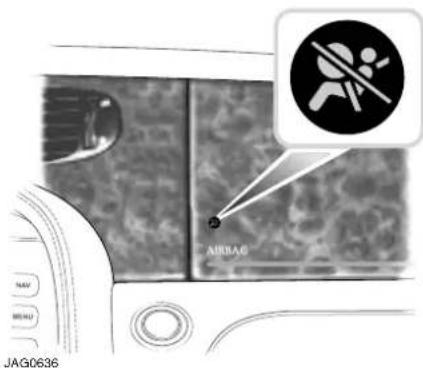
text_image
AIRBAG NAV MESH JAG0636The AIRBAG warning indicator on the passenger facia is associated with the deployment conditions for the front seat passenger airbag only.
- The warning indicator will NOT be lit if the seat is empty and the front airbag will not be activated.
- The warning indicator will NOT be lit if the seat is occupied by a larger child or an adult. The front airbag will be activated and will be deployed in the event of a frontal impact.
- The airbag warning indicator WILL be lit if the seat is occupied by, for example, a small child and in this case the front airbag will not be activated.
- If the passenger adopts a posture (e.g. leaning very far forward) which could cause injury from an inflating airbag, the airbag warning indicator WILL be lit and the front airbag will not be activated.
Note: Whenever the airbag warning indicator on the passenger facia is illuminated, the front passenger airbag will not be deployed in the event of an impact.
Driving position
WARNING:
Driver and front seat passenger should always move their seats as far rearwards as is practical.

natural_image
Diagram of a person sitting in a car with a circular no-smoking symbol, no text or labels presentSince the risk zone at the time of deployment is the first 55 mm – 75 mm (2 to 3 inches) from the airbag cover, sitting back 254 mm (10 inches) provides a clear margin of safety. Very few drivers are unable to achieve and maintain that safety gap.
The vast majority of drivers who do not now sit that far back can change their position and achieve that distance.
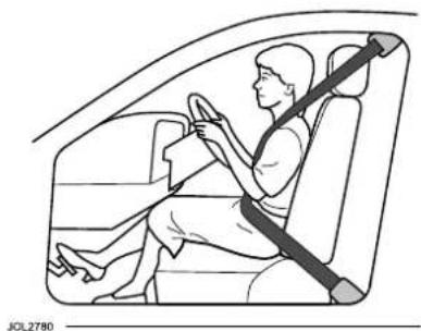
natural_image
Line drawing of a person sitting in a car with a seatbelt, no text or symbols present- Use seat belts.
Occupant Protection
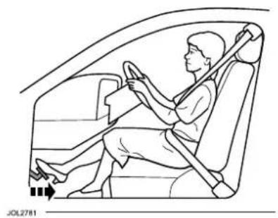
natural_image
Line drawing of a person seated in a car, wearing a seatbelt and driving (no text or symbols)- If adjustable pedals are fitted, move them towards the seat.

natural_image
Diagram of a person seated in a car with a seatbelt, showing directional arrows indicating movement (no text or symbols present)- Move your seat as far rearwards as you can while still comfortably reaching the pedals.
Recline the back of your seat one or two notches from the upright position. If reclining the back of your seat makes it hard to see the road, raise the seat.

natural_image
Diagram of a person seated in a car, showing seatbelt and steering wheel (no text or symbols)- Tilt the steering wheel/column downwards so as to point the airbag at your chest instead of your head and neck. Adjust the steering wheel/ column fore/aft so that it extends towards the driver as little as possible, ensuring that the airbag has plenty of room to deploy.

natural_image
Diagram of a person seated in a car, showing steering wheel and seatbelt (no text or symbols)- Sit in the centre of the seat with the head as close to the head restraint as possible.
* Ideally, drivers should sit with at least 254 mm (10 inches) between the centre of their breastbone and the cover of the steering wheel airbag.
Occupant Protection

WARNING:
Adjust the head restraint so that it is just behind your head and never behind your neck.
Note: Seat, steering wheel and pedal adjustment controls are described later in this section, pages 68, 74 and 76 respectively.
Whiplash protection

text_image
JAG0528LBoth front seats are equipped with Active Head Restraints (AHR) which reduce the risk of neck and spinal injury (whiplash) in the event of a rear impact.
When activated, the head restraint moves upwards and forwards, cushioning the occupants' head.
After activation, the whiplash protection mechanism automatically resets and does not require to be replaced.
Airbag service information

WARNING:
Do not attempt to service, repair, replace, modify, or tamper with, any part of the SRS. This includes wiring or components in the vicinity of SRS components. Doing so may cause the system to trigger, or render the system inoperative, either of which may result in death or serious injuries.

WARNING:
Do not use any electrical test equipment, or devices in the vicinity of SRS components or wiring. Doing so may cause the system to trigger, or render the system inoperative, either of which may result in death or serious injuries.
All of the following operations should only be carried out by a Jaguar Dealer/Authorised Repairer, or suitably qualified person:-
- Removal or repair of any wiring or component in the vicinity of any SRS components.
• Installation of electrical, or electronic equipment and accessories. - Modification to the front or sides of the vehicle exterior.
- Attachment of accessories to the front or sides of the vehicle.
Occupant Protection
Airbag disposal

WARNING:
Do not attempt to service, repair or modify the airbag system or its electrical fuses. All work on the airbag system, including renewal after deployment must be carried out by an authorised Jaguar Dealer/Authorised Repairer.
In the event of the vehicle being dismantled, airbag module removal and disposal MUST be made by a qualified person. Instructions can be obtained from a Jaguar Dealer/Authorised Repairer.
Child Safety
CHILD AND INFANT SAFETY

WARNING:
Children must be restrained by a child safety restraint that is suitable for their weight and size.

WARNING:
Crash statistics show that children are safest when properly restrained on the rear seat.

WARNING:
Do not use a forward facing child seat until the child using it is above the minimum weight of 9 kg (20 lb.) and able to sit up unaided. Up to the age of two, a child's spine and neck are not sufficiently developed to avoid injury in a frontal impact.

WARNING:
Do not allow a baby or infant to be held or carried on the lap. The force of a crash can increase effective body weight by as much as thirty times, making it impossible to hold onto the child. Children typically require the use of a booster seat appropriate to their age and size, thereby enabling the seat belts to be properly fitted, reducing the risk of injury in a crash. Children could be endangered in a crash if their child restraints are not properly secured in the vehicle.

WARNING:
Do not use a child seat that hooks over the seat back. This type of seat cannot be satisfactorily secured and is unlikely to be safe for your child.

WARNING:
Do not use a child restraint on a seat with an operational airbag in front of it. There is a risk of death or serious injury when the airbag deploys.
It is very important for all infants and children under 12 years of age to be restrained in a suitable child safety seat appropriate to their age and size.
Note: In some countries legislation prohibits children travelling in the front of a vehicle. Ensure that you are familiar with the legislation in force where the vehicle is being used, and are in full compliance.
Child Safety
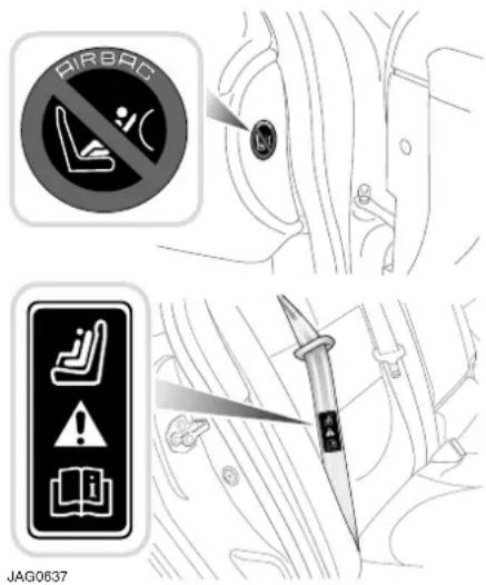
text_image
AIRBAC JAG0637
WARNING:
Original text according to ECE R94.01. Extreme hazard! Do not use a rearward facing child restraint on a seat protected by an air bag in front of it!
The symbol affixed to the end of the facia on the passenger side is to warn against the use of a rear facing child seat when the front passenger airbag is fitted and operational.
Jaguar Cars Limited strongly recommend that at all times children should be carried in the rear seats.
If, however, you have no alternative but to place a child in the front passenger seat, use only a forward-facing child seat with the passenger seat set fully rearward and in its lowest position.
Infant Safety
Babies and small children who cannot sit up by themselves should be carried in an approved baby seat.
In many countries legislation governs how and where children should be carried when travelling in a vehicle. It is the responsibility of the driver to comply with all regulations in force in the country where the vehicle is being used.
Note:
It is important to read and understand all the information contained in this handbook relating to child safety before carrying a child in your vehicle. If you are unsure about any aspect of this information, contact your Jaguar Dealer/Authorised Repairer.
Make sure you read the information in this section which contains:
- General advice about the use of child restraints.
- Specific information about installing a non-ISOFIX child restraint.
- Specific information about fitting the ISOFIX child restraint system.
Child Safety
SEAT POSITIONING
Summary of the Law
In all countries there are regulations governing the use of restraint systems for children and babies. Infants and children must be seated in an approved safety device, which is suitable for the weight and size of the child. A child restraint must meet the regulations enforced in the country where it is used and the approval number and the weight category have to be clearly labelled on the seat.
Generally, the following law applies:
- Children under three years of age must be secured in an appropriate child restraint.
- Children aged 3 to 11 years and less than approximately 1.5 metres (5 feet) in height should be secured in an appropriate child restraint, if available. Otherwise, the adult seat belt must be used.
- For children aged 12 or 13 years, or a younger child approximately 1.5 metres (5 feet) or more in height, the adult seat belt must be used.
- In all three cases above, it is the responsibility of the driver to ensure that the safety of children travelling with them is adequately provided for.
- From 14 years of age, all passengers should use the adult seat belts provided and it is their own responsibility to do so.
Note: Failure to comply with the law could result in prosecution and could affect insurance cover. Remember the driver has responsibility for other passengers under 14 years and the careful stowage of luggage and loose items.
Holding a baby or child in a person's arms is not a substitute for a child restraint system. Do not use a seat belt to restrain more than one person.
In an accident, a baby or child held in a person's arms can be crushed between the vehicle's interior and a restrained person.
The child can also be injured by hitting the interior or by being thrown from the vehicle during a sudden manoeuvre or impact.
Injury can also be caused if the baby or child is allowed to ride on the seat unrestrained. Other occupants should also be properly restrained to help reduce the chance of injuring the child.
Do not allow children to stand in the space between the seats, or on the passenger seats.

WARNING:
Do not put an adult seat belt around two children.

WARNING:
Choose a child seat that sits securely on the seat cushion and against the seat back.

WARNING:
Always use the top tether to secure a forward facing child seat, where possible.
Child Safety
Suitability of each passenger seat position for the carriage of children up to 12 years of age, or 1.5 m (5 feet) tall, and the installation of child restraint systems:
Note: The information contained in the following table may not be applicable to all countries. If you are in any doubt regarding the type and fitment of child seats seek advice from your Jaguar Dealer/Authorised Repairer.
| Mass Group(with approximate age) as indicated on child restraint | Vehicle Seating Position | ||
| Front Passenger* | Rear Outboard | Rear Centre | |
| 0 = Up to 10 kg (22 lb)(birth to 10 months) | X | U | U |
| 0+ = Up to 13 kg (28 lb)(birth to 18 months) | X | U | U |
| I = 9 to 18 kg (20 - 40 lb)(9 months to 5 years) | UF U & L U | ||
| II = 15 to 25 kg (33 - 55 lb) (4 to 7 years) U | U U | ||
| III = 22 to 36 kg (48 - 80 lb) (6 to 12 years) | U U U | ||
| Key:U: Suitable for Universal category restraints approved for use in this mass group.UF: Suitable for forward facing Universal category restraints approved for use in this mass group.L: Suitable for particular vehicle specific child restraint given below. These restraints may be of the specific-vehicle, restricted or semi-universal categories.X: Seat position not suitable for child restraint in this mass group.The safest place to transport children is the rear seat.* Jaguar recommend that the vehicle front passenger seat be positioned fully rearward with the cushion adjusted to its highest position when installing child restraints. | |||
| Type L Child Restraint = Jaguar branded Romer Duo ISOFIX Group 1 restraint - see Jaguar Dealer/Authorised Repairer. | |||
Caution: Information given within the table is correct at the time of going to press. However, availability of child restraints may change. Please consult your Jaguar Dealer/Authorised Repairer for the latest recommendation.
Note: The legislation which governs how and where children should be carried when travelling in a vehicle, is subject to change. It is the responsibility of the driver to comply with all regulations in force.
Child Safety
SUITABLE CHILD SEATS
Before you buy a child seat, it is important to note that your child's weight, rather than age, determines the type of seat that is required.
Jaguar recommends that a rear-facing seat with a harness is used for as long as your infant's development allows.
Do not use a forward-facing seat until your child is able to sit up unaided. Up to the age of two, a child's spine and neck are not sufficiently developed to avoid injury in a frontal impact.
Jaguar's recommended Group 1 seat is the Jaguar ISOFIX child restraint system. The ISOFIX seat must always be used with the top tether.
The Jaguar ISOFIX child seat can only be fitted in either of the outer rear seating positions. The ISOFIX seat is supplied with an anchorage kit that must be fitted by your Jaguar Dealer/Authorised Repairer.
When choosing a child seat, it is also important to consider how you plan to use it. For longer journeys, a reclining seat may offer added comfort and support for a sleeping child, while a lightweight design may be easier to lift in and out of the vehicle. It is also worth noting that some children are more suited to a harness-style seat than a booster seat during their toddler years.
Because child seats vary in shape, certain designs may be more stable when mounted on the outer rear seating positions, rather than in the centre. Always check that the child seat can be mounted securely in the required position: if in doubt, speak to your Jaguar Dealer/Authorised Repairer.
A full range of approved child restraints is available from your Jaguar
Dealer/Authorised Repairer, which offers the best possible fit for your vehicle's interior. Your Jaguar Dealer/Authorised Repairer will be able to show you how to install the restraints correctly.
We strongly advise that you do not buy or use a second-hand child seat. The seat may have been used inappropriately, or involved in an accident. In such circumstances, the seat may not protect your child.
SECURING CHILD RESTRAINTS
Some countries have passenger seat belts (not the driver's) with an automatic locking device for use with child seats, your Dealer/Authorised Repairer can give you details.
If engaged, this device allows the belt to be retracted (tightened) but not pulled out. When used to secure a child seat, therefore, the belt will automatically lock at any point to which it has retracted.
Always ensure that child restraint assemblies are fitted in strict accordance with the child restraint manufacturer's instructions. Keep the fitting instructions for future reference.
The following checks should always be carried out:
- Fit the child seat in the correct position and secure with the seat belt in accordance with the manufacturer's instructions. If necessary, remove the head restraint to accommodate a larger child seat.
Child Safety
- Make sure the child seat is fitted firmly to the car seat. There should not be excessive forward or sideways movement.
- Pull the seat belt all the way out to engage the locking device. To fix the seat firmly, retract the belt back onto the reel; a ratchet operation may be felt as the belt retracts. Continue to pay the belt back onto the reel until it fits snugly around the child seat.
- Regularly check and refit the child seat to ensure there is no slack in the installation.
- The seat belt must not be twisted and the buckle must not rest on the child seat frame, as it may snap open in an accident.
- Never modify the seat, or install it differently to the instructions.
The above is a guide only. Depending on the features of a particular child seat, e.g. forward or rearward facing, engage the locking device before or after attaching the belt, as convenient.
Unbuckling the belt and releasing the child seat will allow the belt to resume its normal operation.
Always secure an unoccupied child seat safely. In an accident an unsecured child seat may pose a risk to the vehicle occupants.
If a booster seat is used, position the lap section of the adult seat belt over the child's pelvis. The diagonal seat belt should rest on the child's shoulder, not the neck.
SAFE USE OF CHILD RESTRAINTS

WARNING:
The top tether anchor point must always be used to secure forward-facing child seats (see page 66).
Ensure that there is no slack in the webbing and that the restraints fits the child snugly across the rib cage and hips. These are the parts of the body most able to take the force of an impact.
- Ensure the path and position of an integral harness across the shoulders is appropriate for your child's development – consult the manufacturer's instructions.
- The lap strap should pass across the top of the child's thighs, bearing on the pelvis, not the abdominal area.
- Adjust the harness every time, so that one or two fingers only can be inserted between the child and harness. Different clothing on a child can make a difference to the correct fitting of the harness.
• Make sure the harness webbing is not twisted. - Never modify the seat harness or buckles, as this may affect the quick release mechanism.
• Always secure your child correctly, even for the shortest journey. - Follow the seat manufacturer's instructions for harness adjustments.
Child Safety
Check List - Non-ISOFIX Child Restraints
Follow the check list each time your child travels in the vehicle:
- Carefully follow the instructions provided by the manufacturer of the restraint system.
- Always use the appropriate child restraints and adjust harnesses for every child, every trip.
- Avoid dressing your child in bulky clothing and do not place any objects between the child and the restraint system.
- Regularly check the fit of your child seat and replace seats or harnesses that show signs of wear.
- Ensure that you have removed all slack from the adult seat belt.
- No child seat is completely child-proof. Encourage your child not to play with the buckle or harness.
- Never leave a child unsupervised in the vehicle.
- Activate the rear door child safety locks (see page 27).
- Ensure your child does not exit the vehicle from the side where there is traffic.
Set your child a good example – always wear your seat belt.
ISOFIX ANCHOR POINTS

WARNING:
Do not attempt to fit ISOFIX restraints to the centre seating position. The anchor bars are not designed to hold an ISOFIX restraint in this position.

WARNING:
If the restraint is not correctly anchored, there is a significant risk of injury to the child in the event of a collision or emergency braking.

WARNING:
Child restraint anchorages are designed to withstand only loads imposed by correctly fitted child restraints. Under no circumstances are they to be used for adult seat belts, harnesses, or for attaching other items or equipment to the vehicle.

WARNING:
If removing a head restraint in order to fit a child restraint, always secure the head restraint when storing it. If left loose in the vehicle it may cause death or serious injury during sudden braking or an impact.
Child Safety
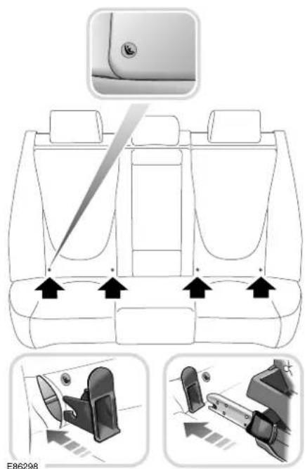
text_image
E86298The anchorage loops are accessible through the gap between the rear seat back and cushion.
Installing the ISOFIX seat

WARNING:
Always follow the manufacturer's instructions supplied with the ISOFIX child seat. The following is to be considered only as a guide.
Always ensure the child seat attachment legs and the vehicle anchorage loops are kept clean and free of dirt.
- Raise or remove the head restraint.
-
Slide the child seat into the locking mechanism.
-
Test the security of the child restraint. To do this attempt to pull the restraint away from the vehicle seat and twist the restraint from side to side. Even if the restraint appears secure you should still check the anchor points visually to ensure correct attachment.
Note: Always ensure that if an upper tether is provided, it is fitted and tightened correctly.
Seat with tether straps - Clip the flexible lower straps to the two anchorage points. Adjust the length of each strap until the seat is held firmly against the vehicle seat back.

natural_image
Illustration of a car comfort seat with seatbelt and seatbelt connector (no text or symbols)
WARNING:
Do not install a child seat with flexible lower attachments in the vehicle centre seat position. The anchorage loops are only provided to install a compatible child seat in the vehicle outboard seat positions.
Child Safety
Check List - ISOFIX Child Restraints
Follow the check list each time your child travels in the vehicle:
• Always attach the top tether when installing the ISOFIX seat.
- Carefully follow the instructions supplied with the child seat.
- Always give the ISOFIX seat a final pull to ensure the lower anchors are secure.
- Always use the appropriate child restraints and adjust harnesses for every child, every trip.
• Make sure your child falls into the correct weight range for the seat.
- Avoid dressing your child in bulky clothing and do not place any objects between the child and the restraint system.
- Regularly check the fit of your child seat and replace seats or harnesses that show signs of wear.
- No child seat is completely child-proof. Encourage your child not to play with the buckle or harness.
- Never leave a child unsupervised in the vehicle.
- Activate the rear door child safety locks, see page 27.
- Ensure your child does not exit the vehicle from the side where there is traffic.
- Set your child a good example – always wear your seat belt.
TOP TETHER ANCHORAGES

text_image
Diagram illustrating airplane seatbelting and lifting mechanism, showing open door, seatbelt with directional arrows, and mechanical component.WARNING:
If provided, the top tether must always be used to secure forward-facing child seats.
The top of the child seat is connected by a short strap to the top tether bracket, to prevent the seat from rotating about the lower anchorages. The top tether brackets are positioned behind the head restraints, under access covers.
Note: If two individual electrically-operated rear seats are fitted, top tethers are only provided for these seats.
Child Safety
Pass the top tether strap under the vehicle rear head restraint, if fitted, to connect to the top tether bracket. Adjust the length of the top tether strap to hold the top of the child seat against the vehicle seat back.
Make sure the child seat is securely fitted and follow the check lists on pages 64 and 66.

WARNING:
Child restraint anchorages are designed to withstand only those loads imposed by correctly fitted child restraints. Under no circumstances are they to be used for adult seat belts or for attaching other items or equipment to the vehicle.
Seats
SEAT ADJUSTMENT

WARNING:
Do not adjust the seat while the vehicle is moving. Doing so could cause loss of vehicle control and personal injury.
All seats, except the rear bench type, are adjusted electrically by switches on the side of the seat cushion. Adjustment can be made with or without the ignition key inserted.
Three different positions can be stored and recalled by a memory system for each seat. (Steering wheel, pedals and door mirrors positions are also memorised for the driver.) See Driving Position Memory on page 84.
Note: It is advisable to move the seat to the correct position in relation to the gear lever and front and side vision before adjusting the steering column, pedals, mirrors and seat belt.
Front seat adjustment
The full range of front seat adjustments are made using the switches on the outboard side of the seat.
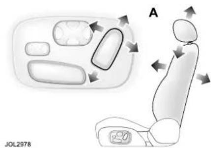
text_image
A JOL2978A - Backrest angle (recline) and head restraint height.
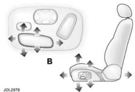
text_image
B JOL2979B - Seat fore and aft movement.
- Move the switch forward or rearward to change the seat fore and aft position.
- Move the centre or rear of the switch up or down to adjust cushion height.
- Move the front of the switch up or down to tilt the front of the cushion.
Seats

text_image
C JOL3271C - If fitted, this varies the cushion extension. Moving the control will change the distance between the front of the cushion and the backrest.
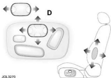
text_image
D JOL3270D - Provides adjustable lumbar support in the lower backrest. Either a 2-way or 4-way switch may be fitted:
- 2-way or 4-way switch: Press the front or back of the switch to increase/decrease lumbar support.
- 4-way switch only: Press the top of the switch to increase higher lumbar, decreasing lower lumbar support. Press the bottom of the switch to increase lower lumbar, decreasing higher lumbar support. Press the front of the switch to increase mid-lumbar and the rear to decrease all lumbar support.
Head restraint adjustment
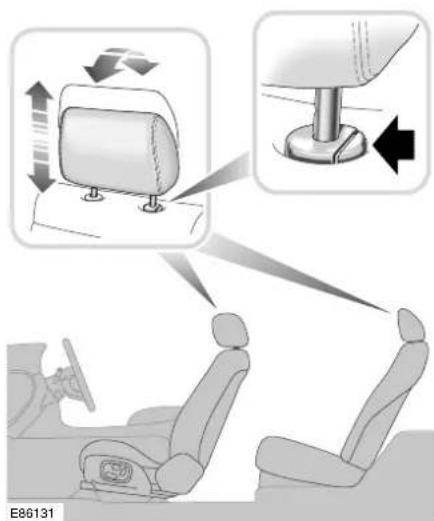
text_image
E86131All head restraints may be manually tilted.
WARNING:
Head restraints are designed to support the head, not the back of the neck. The restraint must be positioned correctly to restrain rearward movement of the head in a collision. An incorrectly adjusted head restraint increases the risk of death or serious injury in the event of a collision.
WARNING:
Adjust the head restraint so that the top of the head restraint is above the centre line of the head. An incorrectly adjusted head restraint increases the risk of death or serious injury in the event of a collision.
Seats

WARNING:
Do not drive, or carry passengers with the head restraints removed from occupied seats. The absence of a correctly adjusted head restraint increases the risk of death or serious injury in the event of a collision.

WARNING:
Never adjust the head restraints while the vehicle is in motion. An incorrectly adjusted head restraint increases the risk of death or serious injury in the event of a collision.
Rear head restraint adjustment
The rear head restraints on vehicles without electrically operated rear seats may be manually adjusted.
Outer head restraints - To raise the outer rear seat head restraints, pull the head restraint upwards. To lower, press the lever in the escutcheon (shown in the upper illustration) and push the head restraint into the seat back.
Centre head restraints - To adjust the rear centre head restraint, tilt the head restraint forwards and lift or push down the head restraint to the desired height. The head restraint can be locked in one of three height positions.
Note: Do not use the levers on the escutcheon to raise or lower the centre head restraints.
Rear seat adjustment
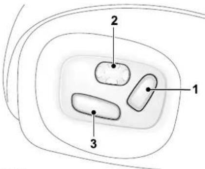
text_image
1 2 3JAG0618
Seats with individual backrests may be adjusted electrically using the switches on the sides of the seat cushions. Adjustment can be made with or without the ignition key inserted.
Seat adjustments are:
(1) - Backrest recline and head restraint height.
(2) - Adjustable lumbar support in the lower backrest: Increase/decrease support and up/down movement, as for front seats. For increased comfort, the front passenger seat fore and aft movement and backrest recline can be controlled from the rear seat immediately behind, using switch (3).
Note: Operation of the front seat by a rear seat passenger and rear seat operation, except for lumbar adjustment, can be disabled from the driver's door switchpack rear feature immobilisation switch. (See Door Windows on page 77.)
Seats
SEAT HEATERS
Some seats have heaters in the backrests and cushions. The heaters have three heat settings and each seat has its own control.
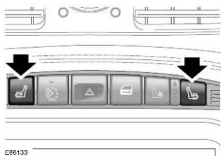
text_image
E86133The front seat heaters buttons are located at the top of the centre console.
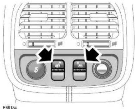
text_image
E86134The rear seat heater buttons are located below the rear air vents.
Note: Storage of the vehicle in a heated garage, body heat or warm ambient temperatures may prevent operation of the seat heater.
With the engine running, pressing a heater button will select the highest heat setting, as shown by three illuminated red indicators.
A second press selects the mid setting (two red indicators) and a third press selects the lowest heat setting (one red indicator). A fourth press turns the seat heater off; all indicators off.
A heater will maintain a pre-set temperature while it is switched on. The heater will automatically switch off if the engine is turned off or if a fault is detected.
Seats
VENTILATED SEATS
Some front seats have a cooling function in the backrests and the cushions.

text_image
JAG0602The front seat ventilation buttons are located at the top of the centre console.
With the engine running, pressing a ventilation button will select the highest fan speed setting, as shown by three illuminated blue indicators.
A second press selects the mid setting (two blue indicators) and a third press selects the lowest fan speed setting (one blue indicator). A fourth press turns the seat cooling fan off; all indicators off.
The cooling fan will automatically switch off if the engine is turned off or if a fault is detected.
HEATED STEERING WHEEL
A heater is incorporated in the steering wheel rim and operates in conjunction with the driver's seat heater. The steering wheel heater is switched on in any of the three driver seat heater positions.
Clock
CLOCK ADJUSTMENT
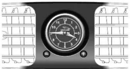
natural_image
Close-up of a mechanical gauge or dial with grid pattern, no visible text or symbolsE86362
The analogue clock is adjusted by pressing the + and - buttons below the dial. Pressing and holding either button will increase the rate of hand movement forwards or backwards as required.
Steering Column
STEERING COLUMN
ADJUSTMENT

natural_image
Mechanical assembly diagram showing a cam mechanism with directional arrows indicating motion (no text or symbols)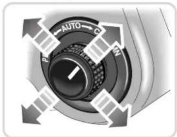
text_image
AUTO PM C INE86302

WARNING:
Never adjust the steering wheel position whilst the vehicle is in motion. Doing so will reduce control of the vehicle, and may cause unpredictable steering movements.
The steering column can be adjusted for tilt and reach by operating the control switch on the left side of the steering column.
Turn the switch to the COLUMN or AUTO position.
Move the switch forwards or backwards to adjust reach.
Move the switch up or down to tilt.
Three column positions may be stored and recalled by the Driver Position Memory system. See page 84.
ENTRY/EXIT MODE
Entry/exit mode provides automatic movement of the steering column and driver's seat to allow easier entry to or exit from the vehicle.
Entry/exit mode is selected by setting the steering column adjustment switch to the AUTO position.
Exit- If the ignition key is in position 0 and the driver's door is opened or if the ignition key is removed, the steering column will move to the uppermost tilt position. The seat will move rearwards unless it is already 40 mm (1.5 inches) or less from its fully rearward position when it will not move any further back.
Entry- When the key is next inserted in the ignition switch and the door is closed, the steering column and seat will return to their previous positions. If, however, the memorised driver position has been changed (using the door memory switch or another integrated key), the steering wheel and seat will move to the new position.
Caution: Do not use steering wheel mounted security devices since movement of the steering wheel in entry/exit mode could result in vehicle damage (e.g. the windscreen) or possible injury to the occupant.
Steering Column
Note:
- If the adjustment switch is moved away from AUTO whilst the steering column is tilted away, the steering column will move back to its memorised position when the key is next inserted in the ignition and entry/exit mode is then cancelled.
- If the adjustment switch is moved during entry/exit operation, steering column movement will stop.
Pedal Controls
PEDAL ADJUSTMENT

WARNING:
Do not adjust the pedals whilst driving.
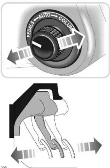
text_image
PEDALS AUTO COLUMN 306E86306
This facility enables the pedals to be moved towards or away from the driver's seat, providing extra adjustment for the driving position. All pedals move together (no individual pedal adjustment) and are electrically controlled from the combined steering column/pedal adjust switch on the left side of the steering column housing. The adjustment can be made with or without the ignition key inserted.
To adjust the position of the pedals, turn the switch to PEDALS, then push it forwards or rearwards to cause a corresponding movement of the pedal assembly.
Three pedal positions may be stored and recalled by the Driver Position Memory system. See Driving Position Memory on page 84. It will not be possible to adjust the pedals if cruise control has been set.
Door Windows
WINDOW OPERATION
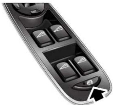
natural_image
Close-up of a car control panel with four buttons and a black arrow pointing to the bottom-right button (no text or symbols visible)E86328
The front and rear door windows are electrically operated by switches located on each door.
Switches on the driver's door control all door windows.
Passengers are provided with a switch to control their door window only.
These switches will only operate the windows when the ignition switch is in position I or II.
The rear window inhibit button (arrowed) immobilises operation of the rear windows by rear seat occupants (and front seat adjustment by rear seat occupants, when fitted).

WARNING:
If children are carried in the rear seats, the isolator switch should be used to prevent operation of the windows. If the windows are operated by young children there is a risk of serious injury or death.

WARNING:
All of the windows have an anti-trap protection system. However, before closing a window care must be taken to ensure that none of the occupants have any part of their body in a position where it could be trapped. Even with an anti-trap system serious injury or death can occur.

WARNING:
Ensure that you remove the ignition keys when leaving occupants in the vehicle. This will prevent unsupervised operation of the windows, which may result in injury.
Raising and lowering the windows
Each switch has two positions to raise the window and two positions to lower the window.
To lower a window, press the switch downwards to the first position until the desired window position is reached, then release.
To raise a window, pull the switch upwards to the first position until the desired position is reached, then release. If the switches are held for longer than six seconds, for example, when attempting to overcome frozen or jammed windows, the window drive will be switched off for a few seconds to protect the window drive motors.
Door Windows
The windows can be operated with the key removed from the ignition switch within ten minutes of the vehicle being stopped provided the driver's or front passenger's door has not been opened. If a rear door is opened the windows can still be operated within the ten minute period.
One-touch operation
Each window has a ‘one-touch’ facility enabling the occupant to fully open or close the window in one quick movement.
Press the switch briefly to the second position to fully open the window in one movement. Pull the switch briefly to the second position to fully close the window in one movement. Window travel can be stopped at any time by pressing the switch again.
Immobilising the rear windows
To immobilise the rear windows (and operation of the front seat by a rear seat passenger, when this feature is fitted), press the rear window inhibit button (see illustration on previous page).
The LED in the button will light up showing that the rear windows cannot be operated by rear seat occupants.
Pressing the button again will enable occupants to operate the rear windows. See also the rear seat adjustment procedure on page 70.
Wind resonance with lowered windows
Due to the sleek exterior of the vehicle, it is possible for a resonance, booming sound, to occur when one or both rear windows are open; this is eliminated by slightly opening an adjacent front window.
Window anti-trap protection
Each electrically operated window has an anti-trap protection feature. If the upward movement of the window detects an obstacle, the anti-trap system will immediately stop the window closing, then move it downwards for a short distance.
Note: If the battery is disconnected or discharged, the window anti-trap feature is lost. When the battery is reconnected or recharged the window anti-trap system must be reset.
To reset the window anti-trap system
- Fully close the window, hold the switch in the close position for two seconds and then release the switch. Wait for two seconds, do not open the window.
- Again, select the same window to close, holding the switch for a further two seconds.
- Check to confirm the operation by opening the window and then use one-touch operation to close the window.
- Repeat for the remaining electrically operated windows.
Door Windows
To override the anti-trap protection
The anti-trap system will also stop the window closing if a blockage or resistance occurs e.g. in the window guide channels. Typically this might be due to icing in winter, but could also be caused by damage or misalignment of the guide channels or seals.
- After the initial attempt to close the window, operate the close switch a second time.
- When the window has reversed from the blockage, operate the switch (within ten seconds) until the window stops again (it will not reverse on the third attempt).
- Immediately operate the close switch again. The window will now move up a short distance with increased force to override the blockage.
- Repeat the override action until the window has closed. Each time the window stops, the switch must be operated immediately to initiate further override action.
If this procedure fails to move the blockage, the anti-trap feature will be lost and must be reset (see previous column) after the blockage has been cleared.
Thermal overload
If the windows are repeatedly opened and closed (e.g. by a child), a protection system will deactivate window operation for a short period to avoid overheating of the window motors.
Mirrors
DOOR MIRRORS
Both door mirrors are adjusted from the driver's door switchpack.

text_image
E86329The four-way adjustment button (1) moves the mirrors to the required position. The selector switch (2) selects the mirror to be moved, left for the left-hand side mirror and right for the right-hand side mirror. When the selector switch is in the centre position, adjustment to either mirror is inhibited.
Each mirror housing is designed to pivot against the vehicle upon impact. To return the mirror to its normal position, manually reposition the housing until it locks into place.
At night, the approach lamps in the door mirrors also switch on automatically when reverse is selected.
Mirror Heating
The door mirrors have heating elements which work when the rear screen heater is switched ON. The mirror heater will clear all ice from the mirror surface.
Caution:
Do not use a scraper to remove ice from the mirrors as this will damage the surface.
Power Foldback (where fitted)
To assist parking by reducing the overall vehicle width, the door mirrors can be folded back.
The button (3) is located in the driver's door window switchpack and will operate the mirrors when the ignition switch is in any position except OFF.
To fold the mirrors inwards press the button. A second press of the button returns the mirrors to their normal driving position.
Note:
- If the button is pressed repeatedly, a thermal cut-out will prevent damage to the vehicle's electronics. If this occurs, wait for five minutes for the cut-out to reset before operating the button.
- If the thermal cut-out operates and leaves the mirrors in the folded position, the mirrors can be folded outwards manually.
- If the door mirrors are repositioned manually (or are knocked out of position), re-engage the mechanism to power the mirror to the foldback position, then outwards to the drive position.
WARNING:
Do not drive the vehicle with the door mirrors in the folded position, except when parking.
Mirrors
Mirror Dip When Reversing
Vehicles are not normally delivered with this feature but, if your vehicle has memory function, it can be fitted by your Dealer/Authorised Repairer.
When reverse gear is selected, one or both door mirrors incline downwards to provide a close up view of the rear side areas.
When the gear selector is moved out of reverse, the mirrors return to their original positions.
INTERIOR REAR VIEW MIRROR
During night time driving with the ignition switched on, the interior rear view mirror will darken automatically in proportion to the amount of glare detected from a following vehicle's headlamps.
When you shift the gear selector lever into reverse, the interior mirror dimming feature will be automatically switched off for a clearer view whilst reversing.
Note:
- Should a mirror assembly become detached from the windscreen, it must be refitted by a Jaguar Dealer/Authorised Repairer.
- Ensure that the windscreen in front of the mirror is kept clean. Where fitted, the moisture sensor for wiper operation is located to the front of the mirror casing. Any dirt may affect the operation of this sensor.
- The automatic darkening of the mirror will not operate properly if the rear window shade (if fitted) is not stowed or if the light that would otherwise strike the mirror is obstructed.
Interior mirror (with compass)
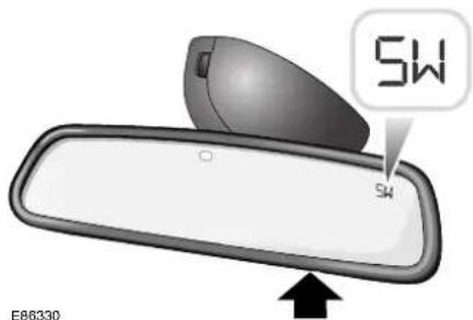
text_image
SW SW E86330Compass operation
When switched on, the compass display on the right-hand side of the mirror surface shows the direction the vehicle is pointing. Eight main directions can be displayed, e.g. N for north, SW for south-west etc.
Setting the compass
With the ignition on, depress and hold the button under the mirror (see the arrow in the illustration above). Depending on how long the button is held will produce the following results:
- 0 to 2 seconds, the display will be blank.
• 3 to 5 seconds, use this to set the zone for geographic location. - 6 to 8 seconds, will cause the compass to RESET the calibration of the compass. The letter C will be displayed in the mirror.
- 9 seconds will set either L for left-hand drive or R for right-hand drive.
Mirrors
Inaccurate compass direction
With the ignition on, push the button for three to five seconds until the Zone selection is shown (a number will be displayed in the mirror compass).
Now press the button repeatedly until the variance zone number for your area (from the map below) appears in the compass display.
The compass is now set to your new location and will give a steady direction heading after about five seconds.

text_image
JOL3251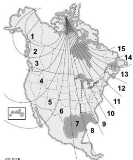
text_image
1 2 3 4 5 6 7 8 9 10 11 12 13 14 15 JOL3115If adjusting the zone setting did not correct the compass heading error, or if the zone was already correctly set for your area then the compass must be recalibrated.
Mirrors
Calibrating the compass
If C is displayed in the compass window instead of the direction, or if the compass displays the wrong heading even when the compass variance zone is correctly set, the compass must be calibrated.
Note:
- Installing items such as a ski rack, antenna or roof rack can cause changes to the vehicle's magnetic field. In these situations the compass will need to be recalibrated.
- The compass may not indicate the correct compass point in tunnels or whilst driving up or down a steep hill. (The compass will show the correct reading when the vehicle moves to an area where geomagnetism is stabilised)
Find a large open space away from traffic, for example, an empty parking lot.
Start the engine and depress and hold the button under the mirror for approximately six to eight seconds until a C appears in the compass display.
Drive the vehicle in a complete circle, 360 degrees, at less than 10 km/h (6 mph) until a direction of travel appears in the compass display.
Alternatively, you can calibrate the compass by driving your vehicle on your everyday routine. Calibration will be completed once the vehicle has completed a full circle.
The calibration process is now complete.
Holding the button depressed for longer than nine seconds enables left-hand drive L or right-hand drive R to be set.
Driving Position Memory
INTRODUCTION

text_image
1 2 M 3 JOL3060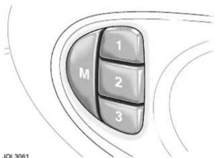
text_image
M 1 2 3 JOL3061This facility, if fitted, enables three different comfort positions to be memorised and recalled for each occupant:
- The driver's seat, steering column, pedals and exterior rear view mirrors.
- Rear passenger seat positions when memory is fitted to these.
The key does not have to be in the ignition switch to make seat, steering column and pedal adjustments, but is required to be in the switch to set the memory.
SETTING AND RECALLING
Setting a memorised position
To store a driver's seat position in the memory:
- Adjust the seat, steering column, pedals and exterior rear view mirrors to the desired positions.
- Insert a key into the ignition switch and leave in the OFF position.
- Push memory button M and the red LED in the switchpack will illuminate for a five second period.
- While the red LED is illuminated, push button 1, 2 or 3 to memorise the configuration. The LED will go out and a chime will indicate that the setting procedure is complete.
By repeating these four steps and pressing the unused buttons, two more driving positions can be stored in the memory.
To set a new driving position, adjust to the desired position and perform steps 2 and 3. The previous memory will be erased and the new position will be set.
The rear passenger's seats can also be memorised by repeating steps 2 and 3 above after adjusting the seat to the desired position.
Recalling a memorised position from the door
Ensure the gear selector lever is in position P.
Press and release the appropriate memory button (1, 2 or 3). The seat, steering column, pedals and door mirrors will move automatically to the memorised position.
Driving Position Memory
Memory recall using an integrated key
The integrated key will recall a memory position when the unlock button is pressed when set as follows:
- Insert a key, to be retained in memory, into the ignition switch.
- Adjust the seat, steering column, pedals and exterior rear view mirrors to the desired positions.
-
Press the M button: The red LED will illuminate for a five second period.
-
Press button 1, 2 or 3 and then press any button on the integrated key. Both button presses must occur while the red LED is illuminated.
-
Repeat for the other integrated key, pressing the remaining memory buttons.
To cancel integrated key memory recall:
- Place a key into the ignition switch and leave in the OFF position.
- Press the M button: The red LED will illuminate for a five second period.
- Press any button on the integrated key (except the panic button, if fitted) then press the M button again. Both button presses must occur while the red LED is illuminated.
Note: If memory recall is performed using an integrated key with the vehicle in entry/exit position, the steering column and seat will not return to the memorised position until either the integrated key is placed in the ignition switch or the driver's door is closed.
Operating tips
- When making adjustments to a set driving position, reset the new position in the same memory channel.
- A driving position will only be memorised during the five second period when the red memory LED is illuminated.
- Previous memory is erased when a new driving position is entered.
Luggage Compartment
LUGGAGE TIE-DOWN LOOPS

natural_image
Diagram showing car interior and exterior view with directional arrows indicating movement or flow (no text or symbols)These loops are not to be used for securing passengers or animals nor as anchorages for child restraints.
It is advisable to distribute luggage weight evenly over the entire luggage floor area.
A range of Jaguar storage accessories, including a luggage retaining net, are available from your Jaguar Dealer/Authorised Repairer.
WARNING:
A luggage net is not designed to restrain objects in the event of a collision.
WARNING:
Locate heavy loads in the luggage compartment towards the front of the vehicle and secure them to stop them sliding. Loose items can be a hazard.
WARNING:
Do not drive with the luggage compartment lid open as exhaust fumes can be drawn into the passenger compartment.
Four loops are positioned in the luggage compartment for attaching straps to secure loads and prevent them from sliding over the luggage floor.
Instruments
INSTRUMENT PANEL

text_image
6 A1000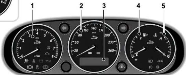
text_image
1 2 3 4 5JAG0638
None of the instruments will show correct indications until the ignition is switched ON (position II).
If the exterior lamps switch is ON and the ignition is ON, the display brightness can be varied using the dimmer switch.
The instruments shown above are:
- Tachometer (Petrol engine vehicles).
- Speedometer.
- Message centre.
- Fuel gauge.
- Engine temperature gauge.
- Tachometer (Diesel engine vehicles).
Tachometer
The tachometer indicates engine speed in revolutions per minute and is calibrated in increments of 250 rev/min extending to:
• 8000 rev/min for petrol engines.
- 7000 rev/min for supercharged engines.
• 6000 rev/min for diesel engines.
Do not allow the needle to enter the red sector.
Speedometer
Speed indications are either:
• Kilometres per hour only, or
- Kilometres per hour, the outer figures, and miles per hour, or
- Miles per hour, the outer figures, and kilometres per hour.
Odometer
The odometer records the total distance covered by the vehicle.
The odometer reading is displayed below the speedometer, along with the trip distance since it was last reset. To reset the trip distance, press the reset button on the trip computer switchpack. The trip distance will roll-over at
16,090 kilometres (or 9999.9 miles).
Instruments
The odometer is displayed in the message centre unless a message has priority or a trip computer function has been selected.
Engine temperature
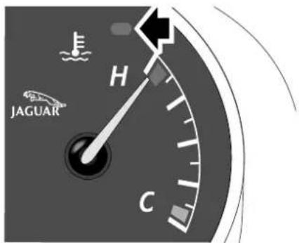
text_image
JAGUAR H CJAG0639
Drive at moderate road and engine speeds until normal operating temperature is reached. This is indicated when the pointer is between the blue (cold) segment and the red (hot) segment.
The engine operating temperature will vary with changes in weather and engine load. The engine temperature may rise in some circumstances, such as:
- Idling for long periods in slow moving traffic.
- Driving up a long hill in hot weather.
- Driving slowly or stopping after driving at high speed.
• Towing a trailer or caravan.
Should the pointer move into the red segment (H) of the coolant gauge, stop the vehicle as soon as it is safely possible, turn off the engine and open the bonnet to allow the engine to cool.
Caution: Serious engine damage can occur if the vehicle is driven whilst the engine is overheating.

WARNING:
The radiator cooling fans may continue to run after the ignition has been switched off but will automatically switch off when the engine has cooled sufficiently.

WARNING:
It is unsafe to run the engine in an overheated condition.

WARNING:
Do not remove the coolant reservoir filler cap while the engine is hot. If it is essential, then protect your hands against escaping steam. SLOWLY turn the cap anti-clockwise to allow the steam pressure to escape completely before removing the cap.
Instruments
Fuel gauge
Indicates the amount of fuel in the tank.
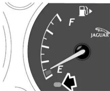
text_image
F JAGUAR EJAG0640
An amber warning indicator is displayed in the gauge when the fuel in the tank is at a low level. The tank should be refilled at the earliest opportunity.
Caution: Never allow the vehicle to run out of fuel. The resulting mis-fire may cause serious damage to the catalytic convertor.
The small arrow, shown beside the fuel pump symbol, identifies on which side of the vehicle the filler cap is located.
Instruments
WARNING INDICATORS
Warning indicators are arranged within the instrument panel.
There are two warning indicators, one red, the other amber, located above the message centre for primary and secondary status of the warnings displayed by the message centre.
RED warning indicators are for primary warnings. A primary warning must be investigated immediately by the driver or a Jaguar Dealer/Authorised Repairer.
AMBER warning indicators are for secondary warnings when the driver must take action and then report the fault to a Jaguar Dealer/Authorised Repairer at the earliest opportunity.
Other indicators within the instrument panel indicate system status, such as blue for high beam and green for direction indicators, when in operation.
Lamp check
A lamp check is initiated when the ignition is switched ON and lasts for three seconds (except the airbag warning indicator which will remain on for six seconds). If any warning indicator remains on after this period, investigate the cause before driving.
Not all lamps are included in the lamp check, for example, high beam headlamps or direction indicators.
Low oil pressure (Red)

This illuminates with the ignition switched ON and should go out once the engine
is running.
If the indicator remains ON once the engine has started or comes ON whilst driving, loss of oil pressure is indicated. STOP the engine immediately and investigate the cause.
Do not restart the engine until the cause of loss of oil pressure has been identified and rectified.
First check the engine oil level, see page 217.
Charge indicator (Red)

Diesel only: The charge indicator will illuminate when the ignition is ON and should
go out when the engine is running.
Diesel and Petrol engines: If the indicator comes ON when the engine is running it indicates that there is either a battery voltage fault or an alternator fault.
Turn OFF all electrical accessories, radio, climate control, rear screen heater etc. Try to use the minimum electrical load as possible, such as power windows, electric sunroof etc. Report the fault to a Jaguar Dealer/Authorised Repairer.
Instruments
Seat belt (Red)

The warning indicator illuminates when the ignition is turned ON and:
- The driver's seat belt is not fastened.
- A passenger is sitting in the front seat and their seat belt is not fastened.
The indicator should go out when the driver's seat belt (and the front passenger's if the seat is occupied) is fastened.
Note: The vehicle must be moving above 16 km/h (10 mph) for the indicator to illuminate if the passenger seat belt is not fastened.
Beltminder
The Beltminder feature is a supplemental warning to the seat belt warning function.
This feature provides additional reminders to the driver that the driver's and/or front passenger's seat belt is unbuckled by intermittently sounding a chime and illuminating the seat belt warning indicator in the instrument panel.
If the vehicle is moving above 16 km/h (10 mph) and one or both front seats are occupied and a seat belt is not fastened, a warning chime will be heard and the indicator will flash.
The chime sound and the indicator flashing will last for 10 seconds and then repeat every 30 seconds for five minutes or until the belts are fastened or the vehicle stops.
If the warning indicator stays ON continuously with the seat belt(s) fastened, report the fault to a Jaguar Dealer/Authorised Repairer. It is safe to drive the vehicle with the indicator ON continuously, provided that the seat belt(s) is properly fastened.
Ensure that all occupants seat belts are fastened before driving.
Note: If a heavy object is placed on the front passenger seat it may activate the Beltminder feature. It is recommended that the object be placed in the luggage compartment.
It is safe to drive the vehicle with the indicator ON continuously, provided that the seat belt(s) is properly fastened. Ensure that all occupants seat belts are fastened before driving.
Although not advisable, it is possible to disable the Beltminder function. Please see a Jaguar Dealer/Authorised Repairer to disable or reinstate this function.
Instruments
Brake (Red)

This illuminates when:
- The ignition is ON and the Electric Parking Brake (EPB) is ON.
• There is a fault with the EPB.
• The brake fluid is low.
If the indicator is ON and there are no associated messages it means that the EPB is applied.
If the indicator flashes, there is a fault with the EPB system and the EPB cannot be applied.
If the indicator is ON and the message PARKBRAKE ON is displayed, it means that the EPB is applied but the vehicle is moving. Release the parkbrake or stop the vehicle when it is safe to do so.
If the indicator is ON and the message LOW BRAKE FLUID message with a RED priority indicator is displayed on the message centre, low brake fluid is indicated. In this case, loss of braking in one, or both, brake circuits may be imminent.

WARNING:
If the message LOW BRAKE FLUID is displayed, DO NOT drive the vehicle until the fault is rectified. Consult a Jaguar Dealer/Authorised Repairer immediately.
Engine malfunction (Amber)

This indicator comes on when the ignition is on and remains on until the engine is started.
If the indicator comes on when the engine is running then there is an engine malfunction.
Specialised diagnostic equipment is required to repair such faults. Report the fault to a Jaguar Dealer/Authorised Repairer.
The vehicle may go to limp home mode, with the possibility of reduced engine performance. Drive the vehicle with caution.
Anti-lock Braking System (ABS) (Amber)

If a fault has been detected in the Anti-lock Braking System (ABS) or the electric EPB
system, this indicator will illuminate.
A warning message will appear with this indicator to indicate either ABS fault or EPB fault.
The brake system will continue to function normally, but without ABS braking.
Should the indicator come on or stay on after the bulb check cycle, stop the vehicle at the first opportunity, turn the engine OFF and then restart.
If the ABS indicator comes on again, the vehicle should be driven to a Jaguar Dealer/Authorised Repairer at the earliest opportunity.

WARNING:
If the ABS and brake warning indicators are ON at the same time, DO NOT drive the vehicle until the fault is rectified. Consult a Jaguar Dealer/Authorised Repairer immediately.
Instruments
Dynamic Stability Control (DSC) (Amber)

The indicator will flash at the rate of twice a second when DSC is operating.
The message DSC NOT AVAILABLE will be displayed and the indicator will be ON continuously when a fault is detected in the system.
If the system is turned OFF, a message DSC OFF will be displayed for four seconds and the warning indicator will remain ON.
Adaptive Cruise Control (ACC) follow mode (Amber)

If ACC is active, this illuminates to indicate that the vehicle is in follow mode and automatically
maintaining the desired gap to the vehicle immediately ahead.
Only applicable to vehicles fitted with ACC.
Airbag (Amber)

If the airbag system develops a fault, the warning indicator will flash and then come ON and
remain on until the fault has been diagnosed and cleared.
Report the fault to a Jaguar
Dealer/Authorised Repairer immediately.
It is safe to drive the vehicle; however, in an accident the airbags may not operate.
Diesel glow plug (Amber)

Illuminates when the ignition is switched ON and switches OFF as soon as the glow plugs
reach their operating temperature,
indicating that the engine may be started.
For more information on starting a diesel engine, refer to page 132.
Low tyre pressure (Amber)

Illuminates when one or more tyres is significantly under inflated. The vehicle should be
stopped as soon as possible and the tyres checked and inflated to the recommended pressure.
If the tyre pressure monitoring system develops a fault, the indicator will flash repeatedly for 75 seconds. The indicator will then remain on. Refer to page 235.
Sidelamps (Green)

Illuminates when the side lamps or headlamps are switched ON either manually or by the autolamp system, if fitted.
High beam (Blue)

Illuminates when the high beam headlamps are switched ON or flashed ON.
Front fog lamps (Green)

Illuminates when the front fog lamps are switched ON.
Rear fog lamps (Amber)

Illuminates when the rear fog lamps are switched ON.
Instruments
Direction indicators (Green)

The appropriate indicator tell-tale will flash when the column
switch is moved up or down to signal a right or left-hand turn.
If a direction indicator fails, the tell-tale will flash at twice the normal rate when that indicator is selected. A message will be shown that a bulb has failed. Fit a new bulb immediately.
Note:
- If a bulb has failed, the audible ticking will sound at twice the normal rate.
- If a trailer or caravan is fitted and a direction indicator bulb fails then the tell-tale will flash at twice the normal rate and a message will be displayed that a rear indicator lamp has failed.
Hazard warning lamps
When the hazard warning is selected, both direction indicator tell-tales flash simultaneously.
Overspeed warning (Amber)

(Gulf Co-operation Council only)
Illuminates if the vehicle speed exceeds 120 km/h (75 mph).
Instruments
AUDIBLE WARNINGS
Various sounds are produced for warning and notification purposes as follows:
| Hazard or Condition Remedy/Chime or | Tone |
| Airbag system failure. A tone sequence is | repeated five times.Report the fault to a JaguarDealer/Authorised Repairer as soon as possible. |
| External lamps are switched on when the driver's door is opened. | A chime will sound for ten seconds as a warning that the lamps are on when the ignition is off and the driver's door is opened.Note:The chime will not sound if the switch is in autolamp position. |
| Hazard warning indicators on. A ticking will | sound until the hazard indicators are switched off. |
| Vehicle armed. This warns that the alarm will | sound shortly unless the system is disarmed by either pressing the unlock button on the key transmitter or placing the key in the ignition switch. |
| Left or right direction indicators on. If the switch has not turned itself OFF,switch the turn indicator OFF when the manoeuvre is completed. A ticking will sound until the indicators are switched OFF. | |
| Memory 1, 2 or 3 configuration saved. A short tone as the memory selection is saved. | |
| Valet mode. This indicates that the valet mode has not been set or that access to a restricted area has been prevented because valet mode has been set. | |
| Seat belt reminder (Not all countries). A chime will sound for six seconds after the ignition is switched on or until the front seat belts, when occupied, are fastened or the ignition switch turned to 0. The chime will also sound at regular intervals for five minutes if the vehicle is moving above 16 km/h (10 mph) and the driver's and/or front passenger's (if occupied) seat belts are not fastened or are unfastened. | |
Instruments
| Hazard or Condition Remedy/Chime or | Tone |
| Electric Parking Brake (EPB). | If the message PARKBRAKE ON is displayed, it means that the parkbrake is applied but the vehicle is moving. Release the parkbrake or stop the vehicle when it is safe to do so. |
| EPB cannot be applied. This sounds a warning that the parkbrake cannot be applied. | |
| Adaptive Cruise Control driver intervene. Action is required by the driver to apply the brakes. | |
| Gear selector not in Park (P). This warns that the gear selector is not in Park (P) when the ignition is turned off. | |
Message centre
MESSAGE INFORMATION
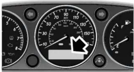
text_image
Close-up of a car dashboard with speedometer, gauge, and control dial showing 240 km/h speed limitE86335
Driver information, messages and data are displayed on the message centre display panel situated within the instrument panel.
For the message centre to operate the ignition must be switched ON (position II).
The primary function of the message centre is to inform the driver of the following:
- Warning messages.
• Temporary alert messages.
• Information messages.
The message centre displays: - The total distance covered by the vehicle.
- Trip computer information.
- Warning messages if system faults are detected.
- Status messages to indicate changes in state of certain vehicle functions.
Messages

WARNING:
If a red warning indicator is displayed, investigate immediately and, if necessary, stop the vehicle as soon as possible but only when it is safe to do so.
Most messages, when displayed, have an associated warning indicator, red or amber, above the display which will come on to indicate the message priority.
Caution: Do not ignore warning messages, take appropriate action immediately. Failure to do so may result in serious damage to the vehicle.
If more than one message is active, each is displayed in turn for two seconds in order of priority.
Messages take priority over the odometer reading or trip computer data and, if active, will be displayed when the ignition is switched ON.
Message centre illumination
The message centre is lit at all times when the ignition is ON, and message brightness is controlled by the dimmer switch.
All information displayed will be brightly lit if the exterior lamps master switch is OFF.
Note: Warning indicators are always brightly lit and are not affected by the dimmer switch.
Message centre
Language selection
The displayed language can be changed to another language, if required.
Press the ML/km button on the trip computer switchpack and whilst pressing, turn on the ignition to position II.
Now press the ML/km button, each press will display a different language. When the desired language is shown, press the A/B button. After three seconds the new language will be displayed for every message.
Note: If you wish to exit the language changing procedure and keep the original language, do not press the A/B button but wait ten seconds or turn the ignition off.
Service interval indicator
The service interval message will only be displayed when the vehicle has less than 3400km (2000 miles) before the service is due.
When the ignition switch is turned to position II and the vehicle has started its service countdown, a message SERVICE REQ'D IN XXXX km (XXXX MLS) is displayed in the message centre. At the same time the AMBER priority indicator is illuminated.
After approximately five seconds, the display reverts to show the pre-set requirements.
When the service distance has been reached, a message SERVICE
REQUIRED is displayed and the red priority indicator will be illuminated.
After approximately five seconds, the display reverts to show the pre-set requirements.
The distance countdown reduces in increments of 50 km or 50 miles, depending on which display units have been selected.
The distance countdown is controlled by the engine management system and is automatically adjusted to allow for driving style and conditions to gauge when the service becomes necessary.
Caution: If no service interval indicator is displayed during the vehicle service cycle, ensure that your vehicle is serviced in accordance with the intervals as stated in the Service Portfolio.
Note: After completion of each service, the Jaguar Dealer/Authorised Repairer will reset the distance display to commence the countdown to the next service.
Message centre
Message list
The table on this and the following pages lists all messages and warning indicators and explains their meaning.
| Message Warning indicator | Priority Indicator | Meaning |
| LOW BRAKE FLUID | Brake Red Displayed when the brake fluid level is low. Complete loss of braking may occur.WARNING:DO NOT drive the vehicle until the fault is rectified. Consult a Jaguar Dealer/Authorised Repairer immediately. | |
| ENGINE COOLANT LOW | None Red Displayed when the engine temperature become excessive. Pull off the road when safe to do so and allow the engine to cool. | |
| RESTRICTED PERFORMANCE | None Red This will be displayed when the vehicle has possible loss of power or driveability. Report the fault to a Jaguar Dealer/Authorised Repairer. | |
| ENGINE SYSTEMS FAULT | Malfunction indicator | Red Displayed when the engine has defaulted to limp home mode. Report the fault to a Jaguar Dealer/Authorised Repairer at the earliest opportunity. |
| DPF FULL SEE HANDBOOK (Diesel models only) | None Red or Amber | Amber displayed when the Diesel Particle Filter (DPF) requires to be regenerated, carry out DPF regeneration, see page 161. If Red priority is indicated contact a Jaguar Dealer/ Authorised Repairer as soon as possible. |
Message centre
| Message Warning indicator | Priority Indicator | Meaning |
| VEHICLE TOO LOW | None Red The air suspension system is too low.Start the engine and wait for the message to clear before driving the vehicle. If the message is displayed while you are driving, restrict your speed until the message is cleared. If the message is persistently shown, inform your Jaguar Dealer/Authorised Repairer. | |
| DRIVERS (or PASSENGERS) DOOR OPEN | None Red The driver's and/or one or more passenger doors are open. Check that all doors are closed before driving. | |
| BOOT OPEN None | Red Check that the luggage compartment lid is closed before driving. | |
| BONNET OPEN None | Red Check that the bonnet is closed before driving. | |
| PARKBRAKE FAULT | None Red Displayed when there is a fault in the Electric Parking Brake (EPB) system. If the red brake warning indicator is flashing the EPB cannot be applied. | |
| CATS SYSTEM FAULT | None Amber Displayed when a fault is detected in the adaptive damping (CATS) system (only those vehicles fitted with adaptive damping suspension). Report the fault to a Jaguar Dealer/Authorised Repairer at the earliest opportunity. | |
| AIR SUSPENSION FAULT | None Amber Drive the vehicle with caution and inform your nearest Jaguar Dealer/Authorised Repairer to have the fault rectified. | |
| ABS FAULT ABS | Amber ABS will not be available. The braking system will work, but care must be used if braking heavily. | |
| BRAKE ASSIST FAULT | None Amber increased brake pedal effort may be required to slow the vehicle down when the engine is cold and engine vacuum is low (diesel engine only). | |
Message centre
| Message Warning indicator | Priority Indicator | Meaning | |
| CHECK PRESSURE RH or LH FRONT or REAR TYRE | TPM (Tyre Pressure Monitoring) System | Amber The | tyre is significantly under inflated. You should stop the vehicle as soon as possible, check the tyres and inflate them to the recommended pressure. |
| CHECK PRESSURE SPARE TYRE | TPM System | Amber The | spare tyre is significantly under inflated. It should be inflated to the recommended pressure. |
| TYRE PRESSURE SENSOR FAULT | TPM System | Amber You | have a temporary spare wheel fitted. You should limit your vehicle speed to 80 km/h (50 mph) and, as soon as possible, replace the temporary spare wheel with a correctly inflated full size wheel. |
| The TPM system sensor has become defective, an unapproved accessory is interfering with the TPM system or you have fitted a wheel and tyre which does not have a sensor. You should seek Jaguar Dealer/Authorised Repairer assistance at the earliest opportunity. | |||
| TYRE PRESSURE SYSTEM FAULT | TPM System | Amber You | have fitted wheels and tyres which do not have TPM sensors fitted. Fit sensors to the wheels at the earliest opportunity. |
| TPM system sensors have become defective, an unapproved accessory is interfering with the TPM system or a general fault has been detected in the TPM system. You should seek Jaguar Dealer/Authorised Repairer assistance at the earliest opportunity. | |||
| TYRE PRESSURES LOW FOR SPEED | TPM System | Amber The | tyre pressures are not suitable for high speed driving. You should reduce vehicle speed and inflate the tyres to the recommended pressure for high speed driving. |
| SERVICE REQUIRED | None Red Displayed when vehicle service is required. | ||
Message centre
| Message Warning indicator | Priority Indicator | Meaning | |
| SERVICE REQ'D IN XXXX MLS (XXXX km). | None Amber | Displayed when there is 3400 km (2000 miles) and less, to next vehicle service. | |
| STEERING COLUMN LOCKED | None Amber | The steering lock system has failed to unlock the steering column. The engine cannot be started. Remove the key and re-insert it into the ignition switch, then try again to unlock the column by turning the steering wheel gently to the left and right (only small movements will be possible). | |
| GEARBOX FAULT | None Amber | It is likely that the driver will experience a degradation of transmission operation and possibly reduced acceleration capability. | |
| DSC NOT AVAILABLE | Stability Control | Amber Displayed when a fault occurs in the stability control system. | |
| DSC ON (or OFF) | Stability Control | Amber (OFF only) | Displayed when the stability control system is switched ON or OFF. The warning indicator will FLASH when the stability control system is switched ON and operating. When the system is switched OFF, the warning indicator in the instrument panel will be illuminated until the system is switched back ON. |
| WASHER FLUID LOW | Low washer fluid level | Amber Indicates that the windscreen wash fluid level is low. If wash/wipe is selected when this message is displayed (even if it has been cleared from the message centre), the programmed wipe after washing will not operate. This is to avoid smearing the windscreen if the reservoir is empty. Top up the washer fluid at the earliest opportunity. | |
| CHECK FUEL FILLER CAP | None Amber | The fuel filler cap may be loose or leaking excessively. | |
Message centre
| Message Warning indicator | Priority Indicator | Meaning | |
| VALET MODE None | None Indicates that the valet switch is selected on. It also indicates that an attempt has been made to open the luggage compartment using the interior release whilst valet mode is selected. | ||
| Note: In most countries it is illegal to use a vehicle with a defective exterior bulb. Bulb replacement information starts on page 197. | |||
| FAILED FRONT LH (or RH) INDICATOR | None Amber Check for any failed front direction indicator lamps and replace. | ||
| FAILED REAR LH (or RH) INDICATOR | None Amber Check for any failed rear direction indicator lamps and replace.This also applies to any trailer/caravan lamps. | ||
| FAILED LEFT (or RIGHT) SIDE REPEATER | None Amber Check for failed side direction indicator repeater lamps and replace. | ||
| EXTERIOR LAMPS SWITCH IS OFF | None Amber This is displayed with the ignition on,the headlamps in the OFF position and it is dark or ambient light level is low.This message is displayed only when the lamps would be on if the switch were in AUTO position. It is a reminder to drivers who normally leave autolamp selected on and may not be aware that it has been turned off. | ||
| APPLY PARKBRAKE | None Amber If the battery has been disconnectedthen the EPB must be applied to reset the system. | ||
| PARKBRAKE ON | Brake None Displayed if the EPB is applied whilstthe vehicle is moving above3 km/h (2 mph). Release the EPB. | ||
| LISTENING None | None When Voice Activation has beenselected and the system is waiting for a voice command/input. | ||
| COLUMN ADJUST | None None The column adjust switch has beenmoved to this position. | ||
| COLUMN ADJUST AUTO | None None The column adjust switch has beenmoved to this position. | ||
Message centre
| Message Warning indicator | Priority Indicator | Meaning |
| PEDAL ADJUST None None The column adjust switch has been moved to this position. | ||
| PEDAL ADJUST INHIBITED | None None The pedals cannot be adjusted when the vehicle is in cruise control operation. | |
| AUTOLAMP DELAY OFF | None None Autolamp delay function has been turned off. | |
| AUTOLAMP DELAY X:XX | None None Changing the time delay will display the newly set time that the headlamps will remain ON after exiting the vehicle. | |
| CRUISE ENGAGED | None None Displayed when cruise control system is operating. | |
| CRUISE CANCELLED | None None Driver has cancelled cruise control or is braking. | |
| CRUISE OVERRIDE | None None Driver is pressing the accelerator pedal. | |
| The following messages only apply to vehicles fitted with Adaptive Cruise Control. | ||
| DRIVER INTERVENE | Red Action by the driver to apply the brakes is required. | |
| SETSPEED XXX KM/H | None Speed set for Adaptive Cruise Control. | |
| GAP None Set the distance (time gap) ← → | ||
| ACC SENSOR BLOCKED | Amber Clean the front of the vehicle in the area of the sensor unit (the sensor is mounted behind the left-hand cover in the lower cooling air inlet). | |
| CRUISE NOT AVAILABLE | Amber Adaptive cruise malfunction. | |
| FORWARD ALERT ON (or OFF) | None Forward alert feature has been switched ON or OFF. A warning will not be given for objects detected in the vehicle path of travel if forward alert is switched OFF. | |
Message centre
| Message Warning indicator | Priority Indicator | Meaning |
| FORWARD ALERT | None Forward alert feature has been switched ON or the setting changed. A warning will be given for objects detected in the vehicle path of travel. A longer gap symbol indicates that the system will warn when detected objects are further away than the previous setting. |
Trip Computer
COMPUTER DISPLAY
The computer memory stores data for a journey or series of journeys until it is reset to zero.
The displayed information is for guidance only, as it can be affected by traffic, road and weather conditions.
Two independent memories are available (A and B) to allow two separate journeys to be recorded concurrently, forexample, work usage and evening/weekend usage.
Trip distance, average fuel economy and average speed will be prefixed A or B depending on the current memory selected.
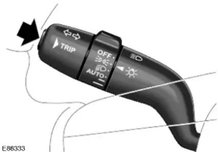
text_image
TRIP OFF 20.05±1 AUTO E86333Press the TRIP button on the end of the left column stalk switch repeatedly to display the data in the following order:
- Odometer.
- Trip distance.
- Range.
• Current fuel consumption.
• Average fuel economy. - Average speed.
- Messages.
Odometer
The odometer shows the total vehicle distance travelled since the vehicle was new.
When the ignition is switched ON (position II) the display shows the odometer reading. This will be followed by any warning messages, if there are any, for example, PASSENGER DOOR OPEN.
The odometer reading is displayed in either miles or kilometres, depending on the units selected with the trip computer.
Trip Distance (A/B)
This displays the distance travelled since the last memory reset.
The maximum trip reading is 16,090 kilometres (9999.9 miles). The computer, either A or B, will automatically reset to zero if this distance is exceeded.
Range
This shows the predicted distance, kilometres or miles, that the vehicle should travel on the remaining fuel, assuming average fuel economy and fuel consumption stay constant.
Current Fuel Consumption
Instantaneous or at the moment fuel consumption, which is continuously updated.
Average Fuel Consumption (A/B)
The average fuel consumption, litres per 100 kilometres or miles per gallon, based on the accumulated distance travelled and the accumulated fuel used.
Average Speed (A/B)
The average speed since the last press of the reset button.
Trip Computer
TRIP COMPUTER
SWITCHPACK
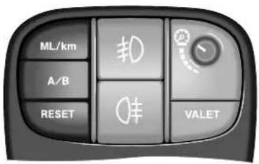
text_image
ML/km A/B RESET #0 # VALET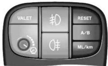
text_image
VALET #0 RESET A/B ML/kmE86334
ML/km
Pressing the 'ML/km' button alternately displays data in metric or imperial units.
A/B
Selects either A or B trip memory. Select the required data using the column stalk TRIP button and then pressing A/B will show the A or B information for that data.
Reset
- One short press clears (hides) the displayed message. Continue to give brief presses to clear one message after another until all messages are cleared.
- Press and hold for three seconds to reset or clear the selected trip A or B, to zero.
Note: If warning messages are hidden, the warning or fault still exists and requires investigation.
Warning and information messages have priority over trip data and, if active, will be displayed when the ignition is at position II.
SETTING THE TRIP COMPUTER
At the start of the journey, or series of journeys, to be recorded, reset the computer memory to zero as follows:
- Press the TRIP button on the end of the left column stalk switch to select a trip function. The computer will display either TRIP A: or TRIP B: data.
- Press the A/B button to select the trip (A or B) to be reset.
- Press the RESET button and hold for three seconds.
The display will read:
RESETTING
TRIP A (or B).
Then it will reset and display:
A: 0 (or B: 0) or the new value.
Note: All trip functions for A or B, depending on which was selected, will be reset.
Trip Computer
CLEARING MESSAGES
Messages can be hidden by pressing RESET on the trip computer switchpack.
One press will hide one message. Once all messages have been hidden, the display will show trip data, a further press will display the odometer reading.
If RESET is pressed again, all active messages will be re-displayed.
Repeatedly pressing the RESET button will cycle through the trip, odometer and message modes.
If a fault occurs when in trip computer or odometer mode, the relevant message will be displayed immediately.
If a trip computer function is selected by pressing the TRIP button while messages are displayed, the trip data will be displayed for ten seconds, then the message will reappear.
Note: Hidden messages reappear after an ignition OFF/ON cycle, if the fault remains.
Exterior Lighting
LAMPS MASTER SWITCH

WARNING:
It is an offence in certain countries to obscure front and rear lamps, direction indicators and reflectors.
Switch positions
The exterior lamps are controlled by the left-hand column stalk switch.
The rotary collar on the stalk has positions for turning the exterior lamps on or off and positions for autolamps/exit delay. These are:
OFF

text_image
TRIP OFF AUTO JOL3190All exterior lamps OFF (except vehicles provided with daylight running lamps).
Sidelamps
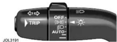
text_image
OFF TRIP AUTO JOL3191Switches on front side lamps, tail, number plate and any other marker lamps required by local legislation.
Headlamps
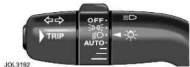
text_image
OFF TRIP AUTO JOL3192With the ignition in position II, this position switches on low beam headlamps, in addition to the lamps switched on in sidelamp position.
The left-hand column stalk switch has two positions for controlling the high beam.
Pulling the switch towards the steering wheel and releasing causes the high beam to flash on and off. The high beam can be flashed at any time when the switch is pulled and will remain ON for as long as the switch is held.
The second position is to switch high beam headlamps ON. With the ignition in position II, first select low beam lamps, and then push the column lamp switch away from the steering wheel.
The blue warning lamp on the instrument panel and the high beam headlamps will come ON.
To turn high beam OFF, pull the column switch towards the steering wheel to return to low beam.
Note: If low beam is switched OFF with high beam still activated, both low and high beam will be extinguished. Both low and high beam will illuminate if low beam is turned on again.
Exterior Lighting
AUTOLAMPS
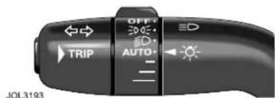
text_image
OFF TRIP AUTO JOL3193A light sensor control, mounted on the front of the facia, monitors exterior light levels and automatically switches the sidelamps and low beam headlamps ON or OFF.
The ignition switch must be in position 'II' and AUTO selected on the stalk for full automatic lamp operation.
When light fades towards dusk, the sidelamps and headlamps will switch ON automatically and the sidelamp warning indicator in the instrument panel will illuminate.
At dawn, as light increases, the sidelamps and headlamps switch OFF automatically.
Keep the windscreen clean and do not cover the sensor. Obstructing the light in this area of the sensor may lead to unwanted operation of the sidelamps and headlamps.
If the windscreen wipers are switched on in auto, slow or fast modes for more than 20 seconds then the exterior lamps will be switched on, if selected to autolamps mode. The lamps will switch off two minutes after the wipers are switched off or will go off straight away if autolamps is de-selected or the ignition is turned off.
EXIT DELAY
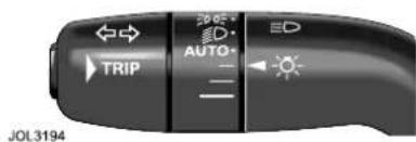
text_image
TRIP AUTO ED JOL3194When parking the car at night, if the headlamps were switched on then they will remain on for a short period after the key has been removed from the ignition switch. This is to give a clearly lit area for occupants leaving the vehicle.
If the exterior lamps switch rotary collar is in the AUTO position there will be no exit delay and the headlamps will turn off when the exterior lamps switch is turned off.
Three settings on the rotary collar set the time that the lamps will remain on after the key is removed from the ignition switch;
- 10 seconds.
- 30 seconds.
- 2 minutes.
Note: The ignition switch must be turned off or the key removed from the ignition switch for this feature to operate.
The message centre shows the delay setting or when this feature is turned off.
HEADLAMP CONVENIENCE
When approaching the vehicle, the sidelamps and headlamps can be switched on by pressing the headlamp button on the remote transmitter.
The lamps will come on for 25 seconds or can be switched off by pressing the remote transmitter headlamp button again.
Exterior Lighting
DAYLIGHT RUNNING LAMPS
In certain countries it is a legal requirement for the exterior lamps to be on during the hours of daylight.
With the rotary collar in the OFF position, low beam headlamps, sidelamps, tail lamps, number plate lamps and, where fitted, side marker lamps will switch on automatically with the following conditions:
• The ignition is turned to position II.
• The vehicle gear selector out of park.
- The Electric Parking Brake is not applied (released).
HEADLAMP LEVELLING
No manual control of headlamp levelling is required on this vehicle. The air suspension will keep the vehicle level.
FOG LAMPS
The fog lamps can only be switched on when the ignition switch is in position II.
Front fog lamps

text_image
VALET #0 RESET A/B ML/kmE86308
With the lamps on in sidelamp or low beam position, press the switch to turn on the front fog lamps. Pushing the switch again will turn off the front fog lamps.
A warning indicator in the instrument panel indicates that the fog lamp is on. If the sidelamps are turned off, the fog lamps will automatically turn off.
Note: The front fog lamps should only be used when visibility is severely restricted by fog.
Rear fog lamps

text_image
VALET 转 RESET A/B ML/kmE86309
The rear fog lamps can only be switched on if the low beam headlamps are on or if front fog lamps are switched on.
Press the switch to turn on the rear fog lamps. Pushing the switch again will turn off the rear fog lamps.
A warning indicator in the instrument panel indicates that the fog lamp is on.
When the side lamps are switched off the fog lamps will go off.
If the sidelamps are left on, but the ignition switch is turned to OFF, the fog lamps will switch off.
Exterior Lighting
DIRECTION INDICATORS
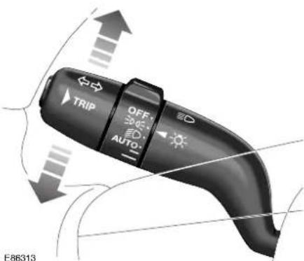
text_image
TRIP OFF: AUTO- E86313The direction indicators, the left column stalk, operate when the ignition is in position II. Move the stalk up for indicating a right turn or move it down to indicate a left turn.
Two positions are provided. The first position, partly moving the stalk up or down, causes the indicator to flash while it is held in this position. On releasing the stalk the indicators stop flashing.
The second position is a full movement of the stalk up or down, which can then be released. The indicators will remain flashing and will cancel when the turn is completed.
An audible ticking and a flashing green arrow on the instrument panel indicates that the selected direction indicator is operating.
Exterior Lighting
Bulb failure
The direction indicators (including those on a trailer, if attached) and side repeaters are monitored for bulb failure.
If a bulb fails when it is on, a message is shown in the message centre. At the same time, the corresponding side green warning indicator will flash at twice the normal rate. The audible ticking will sound at twice the normal rate.
DOOR GUARD/PUDDLE LAMPS
Door guard lamps are fitted to each door to give warning of an open door to passing vehicles.
Puddle lamps illuminate the 'step out' area at night.
Each lamp comes on automatically when the door is opened. If the door is left open the lamps remain on for five minutes and then switch off.
APPROACH LAMPS
Approach lamps are fitted in the door mirrors to provide illumination for the floor area around the front doors.
The approach lamps come on when:
- The vehicle is unlocked using a key, a key transmitter or the central locking switch.
• Using the headlamp convenience button on the key transmitter.
• Reverse gear is selected.
The approach lamps will not illuminate if the autolamp sensor determines that the ambient light is sufficiently bright.
HAZARD WARNING
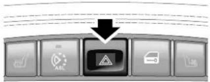
flowchart
graph TD
    A["Start"] --> B{Condition}
    B --> C["Action"]
    B --> D["Car"]
    B --> E["Emergency Response"]
E86312
The switch is in the centre console below the radio and operates with the ignition ON or OFF. Use only in an emergency to warn traffic of a vehicle breakdown or approaching danger.
To operate, press the switch.
The direction indicators, the instrument panel green indicators and the audible warning will operate in unison. The switch symbol will illuminate.
To cancel, press the switch again.
Interior Lighting
CABIN LIGHTING
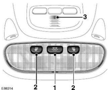
text_image
E86314 1 2 2 3- Front and rear courtesy lamps and footwell lamps.
- Reading/map lamps.
- Centre console illumination.
Interior lighting comprises front overhead courtesy lamp and two front and two rear reading/map lamps. Vanity mirror, glove compartment, footwell and luggage compartment lamps are also provided.
Pressing the centre switch (1) in the overhead console turns the front and rear courtesy lamps and footwell lamps on. A second press turns the lamps off.
The centre console area is illuminated by a small lamp from the overhead console (3). This is on whenever the sidelamps are on and can be controlled by the dimmer switch.
Reading/map lamps
The reading/map lamps are turned on and off by individual switches (2).
The reading/map lamps will remain on for up to 15 minutes after the ignition has been turned off.
Rear Lighting
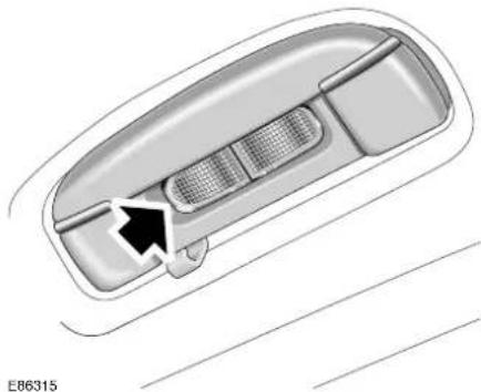
natural_image
Top-down diagram of a car interior showing the dashboard and side panel (no text or symbols)The rear interior lamps can be switched on or off by pressing the lens cover.
Illuminated entry/Exit
The interior lamps fade on when a door is opened and go out when the engine is started or 15 seconds after the last door is closed. If any door is left open, the lamps will fade off after two minutes.
When the vehicle is unlocked with a key or the key transmitter, the courtesy lamps will come on at maximum brightness for two minutes if a door is not opened.
With the engine running, opening any door will put on all interior lamps, they will go out immediately after the last door is closed.
Glove compartment
The glove compartment will be illuminated when the lid is opened.
Luggage Compartment Lighting
The luggage compartment will be illuminated when the lid is opened.
Interior Lighting
DIMMER SWITCH

text_image
ML/km A/B RESET 0 VALET VALET 0 0 RESET A/B ML/kmJAG0604
The instruments, switchpacks, in-car entertainment panel and climate control panel will be lit when the exterior lamps are switched on.
Push and release the knob to extend it for ease of operation.
Rotate the knob to adjust the illumination to the required level.
Push the knob again to place it in the stowed position.
BATTERY SAVER
If the interior lamps are switched on using the centre switch in the overhead console and the ignition switch is turned to position 0, the lamps will automatically turn OFF after 40 minutes.
If the interior lamps are switched on by opening a door and a key is left in the ignition switch in position 0, the lamps will automatically turn off after ten minutes.
If the glove compartment or vanity mirror lamps are switched on and the ignition switch is turned to position 0 or the key is removed, the lamps will automatically turn OFF after 40 minutes.
Parking Assist
INTRODUCTION

WARNING:
Parking aids may not detect moving objects such as children and animals until they are dangerously close. Always use extreme caution when manoeuvring.
Parking assist is always automatically switched on when the ignition is turned on.
Caution: Parking aids are for guidance only, and are not intended to replace the driver's visual checks for obstructions when manoeuvring.
Caution: PDC sensors may not detect some obstructions. Obstructions such as narrow posts, small objects close to the ground, and some objects with dark non-reflective surfaces, for example.
Caution: Systems which use the same frequency band as the front PDC sensors may cause irregular tones to be emitted.
Caution: When washing the vehicle do not aim high pressure water jets directly at the sensors. Do not use abrasive materials or hard/sharp objects to clean the sensors. Only use approved vehicle shampoo.
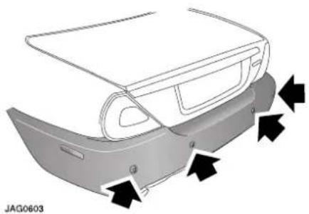
natural_image
Diagram of a car rear bumper with directional arrows indicating movement or force (no text or symbols)Note:
- For reliable operation, the sensors in the front (if fitted) and rear bumpers should be kept free from frost, ice and grime.
- When using a high pressure spray the sensors should only be sprayed briefly and at least 200 mm (8 inches) distance from the sensors.
- Front parking assist may sound spurious tones if it detects a frequency tone using the same band as the sensors, for example, a motor cycle exhaust.
Towing
When an approved Jaguar tow bar electrical system is fitted, the rear parking assist is automatically turned off if a trailer is attached to the vehicle.
Rear fitted accessories
Particular care must be taken with rear fitted accessories, for example, a tow bar or a bicycle carrier, as the rear park assist will only indicate the distance from the bumper to the obstacle.
Parking Assist
PARKING ASSIST

natural_image
Top-down technical line drawing of a car showing its top and front views with propellers (no text or symbols)E86368


When reverse gear is selected and ignition is on, rear parking assist automatically provides an audible proximity warning (to the nearest detected obstacle) when reversing the vehicle, if obstacles are detected within the operating range, shown in the illustration above, between approximately:
- 600 mm (24 inches)
- 1600 mm (63 inches)
Parking Assist

text_image
E86369When both front and rear parking assist are fitted, a switch is located in the overhead console.
Pressing the switch turns front and rear parking assist on or off together. The switch integral warning lamp will come on when the system is turned off or if a fault is detected in the system. A switch is not provided when only rear parking assist is fitted.
Note: The front parking assist will also operate when reverse gear is selected.
Front parking assist provides an audible proximity warning when driving forwards if objects are detected within the operating range, shown in the illustration below in the approximate range:
The front sensors only operate within a fixed speed range in forward gears and are not effective when moving forwards above 15 km/h (9 mph) or when slowing down until below 7 km/h (4½ mph).
If an obstacle is detected at the front or rear of the vehicle, a beep tone will be heard from the front or rear speaker respectively, which increases in rate as the vehicle approaches the obstacle.
The front or rear parking assist beep will become continuous when the obstacle is detected at or within 300 mm (12 inches) from the rear or approximate 250 mm (10 inches) from the front of the vehicle.
If the system has a fault when engaging reverse gear or turning on the ignition, then a single, three second tone will be heard (only once per ignition cycle) and, if fitted, the switch lamp will come on. The system is automatically disabled when a fault is detected.
Horn
DUAL TONE HORN
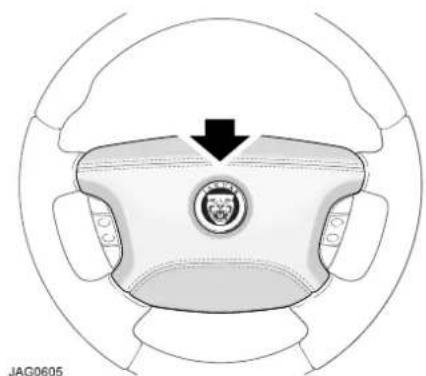
natural_image
Top-down view of a car steering wheel with a logo and arrow indicating direction (no text or symbols on the diagram itself)The dual tone horn is operated by pressing the centre pad on the steering wheel.
The horn also operates as a warning horn if the vehicle alarm system is activated.
Sunroof
INTRODUCTION
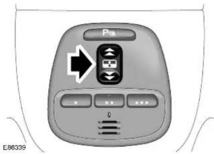
text_image
Pw E86339
WARNING:
Extreme care must be taken to ensure that none of the occupants have any part of their body in a position where it could be trapped by the panoramic sunroof when closing. Although an anti-trap mechanism is fitted, serious injuries can occur.
The sunroof switch is located in the overhead console. The ignition switch must be in either position I or II for the sunroof to operate.
The sunroof has a one-touch facility enabling the occupant to fully open or close the sunroof in one quick movement.
OPERATION
To open the sunroof
- Push the rear of the switch gently upwards to the first position and hold until the sunroof is fully open. The sunroof can be stopped at any open position by releasing the switch.
- To fully open the sunroof with one-touch operation, briefly push the rear of the switch fully upwards to the second position and then release. To stop the sunroof opening, briefly press the switch upwards, forwards or rearwards.
To close the sunroof
- Push the front of the switch upwards to the first position and hold until the sunroof is closed. It can be stopped at any position by releasing the switch. - To close the sunroof with one-touch operation, briefly push the front of the switch upwards to the second position and then release. To stop the sunroof closing, press the switch upwards, forwards or rearwards.
To tilt the sunroof open
- Push the front of the switch upwards and hold until the required position is reached, or until the tilt is fully open, and then release the switch.
To tilt open with one-touch operation
- Briefly push the switch upwards to the second position.
To close the tilted sunroof
- Push and hold the rear of the switch until the sunroof is closed. Briefly push the rear of the switch upwards to the second position to tilt closed with one-touch operation.
Sunroof
Sunshade operation
The sunshade can be manually opened and closed using the recessed handle.
Note: When the sunroof is fully open the sunshade is also fully open and, because the recessed handle is hidden, it cannot be manually closed from this position. The sunroof will need to be fully closed to gain access to the recessed handle.
Wipers and Washers
WINDSCREEN WIPERS
Caution: Do not operate the windscreen wipers on a dry screen. The drag on the wiper mechanism may cause damage.
Caution: In freezing, or very hot conditions ensure that the wipers have not stuck to the windscreen before operating. The drag on the wiper mechanism may cause damage.
Caution: Remove any snow, ice, or frost from the windscreen, around the wiper arms and blades and the screen scuttle before operating the wipers. Snow and ice can cause damage to the wiper mechanism if left uncleared.
The windscreen wipers and screen wash functions are controlled by the right-hand column stalk switch and only operate with the ignition in position II.
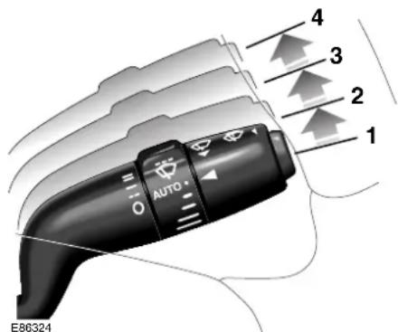
text_image
4 3 2 1 AUTO E86324Moving the stalk up or down operates or turns off the windscreen wipers.
The stalk functions are as follows:
- Position (1): The windscreen wipers are OFF and parked.
- First position (2): Intermittent wipe.
• Second position (3): Slow speed wiper operation. - Third position (4): High speed wiper operation.
Intermittent wipe
When intermittent wipe is selected the delay between wipes can be varied. Turn the collar to vary the delay from 2 seconds to 20 seconds.
Flick wipe
Pull the column switch towards the steering wheel for a single wipe. Holding the column switch in this position will operate the wiper continuously at slow speed until released.
Rain sensitive wiper control
When AUTO, (turn the rotary collar to AUTO) and intermittent wipe are selected, the wipers will automatically operate to clear the windscreen when rain falls on to the windscreen, or when moisture is present.
For the wipers to operate, the ignition switch must be in position II.
Note: When starting a journey with a wet windscreen, the rain sensing wipers will not operate immediately the ignition is switched on. Therefore, a flick wipe should be used to clear the windscreen of any moisture.
Caution:
Ensure that AUTO is not selected when entering a car wash or damage to the wiper blades/arms can occur.
Wipers and Washers
WINDSCREEN WASH/WIPE
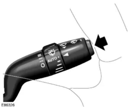
text_image
AUTO E86326
WARNING:
Some screenwash products are flammable, do not allow screenwash to come into contact with sources of ignition.
Push the button on the end of the stalk to obtain the wash/wipe programme.
If the wipers are selected off or intermittent, the washers will operate at slow speed during the washing action when the button is pressed. When the button is released, the wipers will complete up to three further wipes. A single wipe will take place four seconds after the last wipe to clear any drips of water from the windscreen.
If rain sensitive wipers are fitted and selected then the wipers will operate until no moisture is detected.
HEADLAMP POWERWASH
The headlamp powerwash units (if fitted) are mounted between the front headlamps.
The headlamp powerwash feature will operate if the ignition is in position II and low or high beam headlamps are switched ON. It will not operate if the washer fluid level is low.
When the windscreen wash/wipe button is pressed, the headlamp powerwash directs two short bursts, three seconds apart, at the headlamps. If the wash/wipe button is held, the headlamp wash cycle will continue for up to 20 seconds.
The headlamp powerwash will operate the first time the wash/wipe button is pressed and thereafter every sixth succeeding wash/wipe operation. If the headlamps or ignition are switched OFF and ON again, headlamp powerwash will operate on the next press of the wash/wipe button.
Note: If the washer fluid level is low in the reservoir, the windscreen wipers will not operate when windscreen wash is selected, even though there may be washer fluid remaining in the reservoir and sprayed onto the screen. This is to prevent damage to the blades, or scratching of the glass, or smearing dirt across the screen.
Parkbrake
natural_image
Diagram showing two car intake windows with directional arrows indicating movement, no text or symbols presentThe switch which operates the EPB is mounted on the centre console to the rear of the gear selector.
To engage the EPB, pull the EPB switch upwards and release. The switch will return to the neutral position. The EPB warning/brake fluid low warning indicator on the instrument panel will illuminate.
To disengage the EPB, with the ignition switch in position II or with the engine running, apply the footbrake and press the EPB switch down.
The EPB is automatically released when the gear selector is moved from the Park P position.
If the vehicle is stationary and the gear selector is in D or R and the EPB is applied, then the EPB will automatically release when the accelerator pedal is depressed.
Inadvertent operation of the EPB whilst the vehicle is in motion will cause the message PARKBRAKE ON to be displayed on the message centre, the warning indicator in the instrument panel will be illuminated and a warning chime will sound.
If the EPB is applied whilst the vehicle is moving, push the switch down to release it. If the switch is in the neutral position after EPB application, depressing the accelerator pedal will release the EPB.
Note: If the vehicle is in motion, the EPB should only be used as an emergency brake.
The EPB is automatically applied when the key is removed from the ignition switch. If you wish to keep the EPB off, press and hold the EPB switch down and, at the same time, remove the key.
Caution: Take care that the vehicle is safely parked to prevent it from rolling if you wish to leave the EPB off.
The warning indicator in the instrument panel will remain on for a short time if the EPB is applied when the key is turned to position 0 or if the key is removed.
If the battery has been discharged or disconnected the message APPLY
PARKBRAKE will be displayed when the ignition is next switched on. Depress the footbrake and pull the EPB switch up to apply the EPB. This is required to reset the EPB system which will now function correctly.
Interior Features
ACCESSORY POWER POINTS

natural_image
Top-down view of a car air conditioning control panel showing buttons and ventilation grilles (no text or symbols visible)E86361
There are two sockets to provide a power source for accessories, such as a 12-volt vacuum cleaner or mobile phone.
One is fitted to the end of the centre console to the left of the cigar lighter, beneath a flip lid.
The other accessories socket is located in the glove compartment (not shown).
Caution: Only Jaguar approved accessories should be plugged into the power sockets. Using any other equipment may damage the vehicle's electrical system. If you are in any doubt contact a Jaguar
Dealer/Authorised Repairer.
Caution: The engine should be running when using accessories for long periods. Failure to do so can discharge the battery.
CIGAR LIGHTER AND ASHTRAY
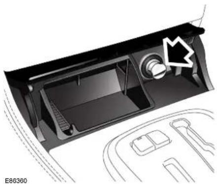
natural_image
Interior view of a car dashboard with air vent and control panel (no text or symbols)Push the lid to gain access to the front cigar lighter and ashtray. To operate the cigar lighter the ignition must be on, press the lighter in and wait until the element has heated, it will then pop-up.
Note: Never hold the lighter knob down. Do not attempt to remove particles from the heating element, it is self-cleaning.
The cigar lighter is designed to be used just to heat the lighter element and is not for providing a power source for accessories.
To empty the ashtray, lift it out vertically and remove. After emptying, push the ashtray into the opening until it snaps back into place.
WARNING:
Do not use the ashtrays for disposing of waste paper, or other combustible items. The resulting fire may cause death or serious injury.
Interior Features
To remove the passenger door ashtray, open the ashtray cover by lightly pressing downwards. When the cover is fully open, lightly push it towards the door trim and remove.
SUN VISORS AND VANITY MIRRORS

natural_image
Illustration of a car rearview mirror with a close-up inset showing the blade and blade motion (no text or symbols)Adjustable sun visors can be swung downwards or unclipped and swung sideways to reduce sun glare.
The sun visors are fitted with illuminated vanity mirrors, behind a hinged flap. The lamp comes on when the flap is lifted.
SUNGLASSES STOWAGE
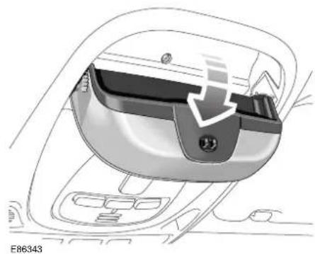
natural_image
Interior view of a car headset showing the dashboard and seat area (no text or symbols visible)A compartment for stowing sunglasses or spectacles is located in the overhead console. Push upwards to open.
Interior Features
CENTRE CONSOLE
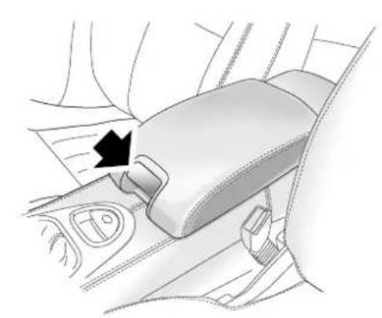
natural_image
Diagram of a car seatbelt mechanism showing the grip and seat area (no text or symbols)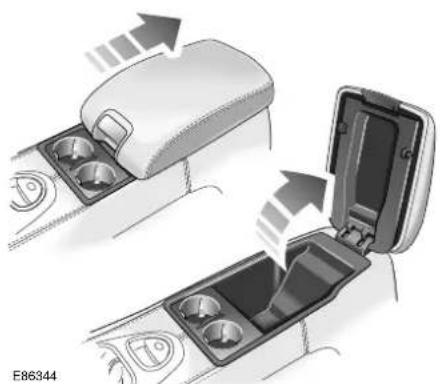
natural_image
Diagram showing car interior compartments with arrows indicating flow direction (no text or symbols)The centre console carries the armrest, cupholders, the cubby box and (where fitted) the phone. At the rear of the centre console is a cigar lighter and accessory power point.
Cupholders
WARNING:
The cup and bottle holders should only be used for soft containers. Containers which are hard (cans, metal, ceramic, hard plastic etc.) can cause serious injury if the vehicle is involved in an accident, sudden manoeuvre or braking.
WARNING:
Do not carry open drinks containers. Hot liquids can cause serious injury when spilled and may damage the vehicle.
WARNING:
Do not drink, or use the drinks holders when driving. Doing so would break concentration, which may result in loss of control.
The sliding armrest is hinged at the rear and has a release button located on the front of the armrest. The chromed button is pulled upwards to raise the armrest and gain access to the cubby box and (when fitted) the telephone.
To expose the two cupholders, slide the armrest rearwards.
Interior Features
REAR ARMREST
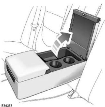
natural_image
Diagram of a car interior with an open trunk and two circular compartments, showing a directional arrow (no text or symbols present)
WARNING:
The cup and bottle holders should only be used for soft containers. Containers which are hard (cans, metal, ceramic, hard plastic etc.) can cause serious injury if the vehicle is involved in an accident, sudden manoeuvre or braking.

WARNING:
Do not carry open drinks containers. Hot liquids can cause serious injury when spilled and may damage the vehicle.

WARNING:
Do not drink, or use the drinks holders when driving. Doing so would break concentration, which may result in loss of control.
Depending on vehicle specification there can either be a rear armrest or a rear centre console fitted.
To access the cupholders in the rear armrest, press the two buttons on the rear hinged lid and raise it. The cupholders can then be used as required.
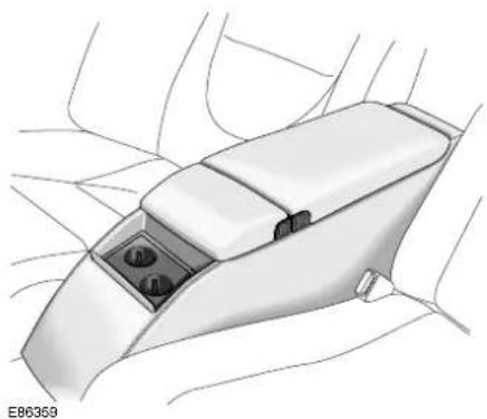
natural_image
Diagram of a car headrest with internal compartments and wiring (no text or symbols)To access the cupholders in the rear centre console, push and release the rear of the lid which will then fold forwards exposing the two cupholders. To close the lid, fold rearwards and push it shut to cover the two cupholders.
Interior Features
SUNBLINDS
Rear sunblind
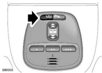
text_image
E86355Push the switch to raise the sunblind. To lower the sunblind, push the switch again.
Side sunblinds
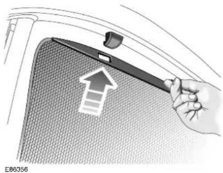
natural_image
Illustration of a hand holding a tool over a textured surface with an upward arrow, no text or symbols present.The rear door window sunblinds are manually operated by lifting the blind and securing it in the two clips provided. To lower the blind just unhook it from the clips and lower it gently back into the stowage.
Quarter light sunblinds
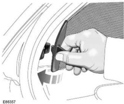
natural_image
Illustration of a hand using a tool to adjust or install a car component, with no visible text or symbols.
Take care when releasing the quarter light blind because it could strike your face if it slips from your hand.
Quarter light blinds have a single securing clip. Pull the blind rearwards and locate it in the clip. To stow the blind, unhook it and gently let it return into the stowage.
Interior Features
GLOVE COMPARTMENT
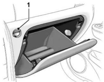
natural_image
Technical diagram of a car door handle and compartment, showing internal components without any text or symbolsJAG0641
To open the glove compartment, press and release the button (1).
If the glove release button is pressed more than 15 times within a 20 second duration, the glove opening function will be inhibited.
It will then be necessary to wait for 20 seconds before the glove opening function will be reactivated.
The glove compartment cannot be opened when the following conditions occur:
-
The vehicle is being driven using the green-headed valet key and valet mode has been selected, or,
-
The vehicle is centrally or double-locked via the remote transmitter, or via the driver's door key barrel by turning the key towards the rear of the vehicle and releasing, or, after auto-relocking occurs.
BUSINESS TRAY
(where fitted)
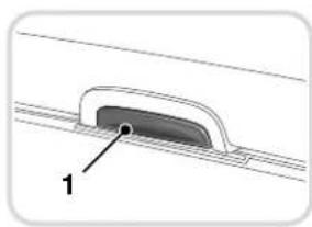
natural_image
Diagram of a mechanical component with labeled part '1' (no text or symbols beyond label)
natural_image
Illustration of a car interior compartment with hand placement and textured floor (no text or symbols)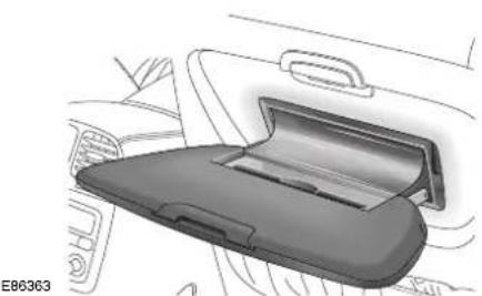
natural_image
Interior view of a car showing the rear intake manifold and dashboard (no text or symbols visible)Push the button (1) to release the tray.
To extend the tray, pull it towards you. This will expose the pen holder slot.
To replace the tray, push it forwards to its non-extended position and then lift it upwards and push it into the seat back until it clicks into place.
Do not use the tray in a moving vehicle.
Stow away securely when not in use.
Engine Starting
BEFORE STARTING
Before starting the engine, new owners/drivers should familiarize themselves with the layout and operation of the controls and instruments.

WARNING:
Before attempting to start the engine, check that the Electric Parking Brake (EPB) is ON and the gear selector lever (automatic transmission) is in position P or N.
Automatic transmission
When the vehicle is stationary the automatic gear selector may be left in D, 2, 3 or 4, unless the vehicle is to be parked. When stopping for traffic lights, junctions etc., either select P or apply the EPB and select N.
Manual transmission
When the vehicle is stationary it is advisable to apply the EPB and to move the gear selector to the Neutral position.
STARTING A PETROL ENGINE

WARNING:
Never start the engine, or leave it running, when the vehicle is in an enclosed space. Exhaust gasses are poisonous and can cause unconsciousness and death if inhaled.
The engine cannot be started until the automatic transmission gear selector is in N or P.
Insert the key into the ignition switch and turn clockwise to position II to switch on the ignition.
When the key is turned to position III the starter motor will turn the engine until:
- The key is released and automatically returns to position II.
• The ignition switch is turned to 0 or 1. - The gear selector is moved out of P or N (automatic transmission vehicles).
• The engine starts.
Do not use the starter continuously for longer than six seconds. Continued use of the starter will discharge the battery and may damage the starter mechanism. Wait until the engine stops turning before re-using the starter.
When the engine starts, release the key.
The red charge warning indicator in the instrument panel should go out when the engine is running.
If the engine fails to start
If an ignition key is placed in the ignition switch and turned to position II and the alarm security indicator is flashing, it is possible that the engine will not start. In any event, please contact a Jaguar Dealer /Authorised Repairer to investigate the cause of the indicator flashing.
Caution: If the engine fails to start, do not continue cranking as this will discharge the battery. It may also damage the catalytic convertor due to unburnt fuel passing through the exhaust.
It is possible that the fuel system inertia switch may have tripped, see page 184 for the resetting procedure.
Engine Starting
If the engine persistently fails to start and flooding is suspected, depress the accelerator pedal fully, hold it in this position and turn the key to position III for six seconds. Release the key, remove your foot from the accelerator pedal and then attempt to restart the engine.
Note: The engine cannot start whilst the pedal is fully depressed, it must be released to enable the engine to start.
If the engine still fails to start, switch the ignition OFF and contact a Jaguar Dealer /Authorised Repairer.
Stopping a petrol engine and locking the steering
Turn the key from position 11 to the lock position 0. This turns off the ignition and stops the engine. The steering will be locked when the key is removed from the switch.
Leaving the key in position I or II will discharge the battery.
STARTING A DIESEL ENGINE

WARNING:
Never start the engine, or leave it running, when the vehicle is in an enclosed space. Exhaust gasses are poisonous and can cause unconsciousness and death if inhaled.

Insert the key into the ignition switch and turn clockwise to position II. Ensure the glow
plug indicator illuminates.
Once the indicator has extinguished, depress the clutch and do not touch the accelerator pedal. Turn the key to position III to turn the starter motor. Continue to operate the starter motor without pausing, until the engine starts. Once the engine has started, release the key, which will return to position II.
Caution: If the engine fails to start, do not continue cranking as this will discharge the battery.
If the engine stalls or fails to start, the key must be turned to position I before attempting to restart.
At extremely low temperatures it may be necessary to crank the engine for up to 30 seconds.
Caution: Do not let the engine run under full load immediately after starting. Give the lubricating oil time to reach the oiling points to prevent damage to the engine.
Stopping a diesel engine and locking the steering
Release the accelerator pedal. Wait until the engine has reached idle speed, then turn the key from position II to the lock position 0. This will turn off the engine. The steering will be locked when the key is removed from the switch.
Caution: Do not depress the accelerator pedal. If the engine is switched off at high speed, the turbocharger will continue running after the engine oil pressure has dropped to zero. This will cause premature wear of the turbocharger bearings.
Leaving the key in position I or II will discharge the battery.
Engine Starting
Caution: Especially after driving at high engine speeds for any length of time, it is important to let the engine run for a time (one minute) while stationary before switching it off. This allows the turbocharger turbine blades to cool off, while lubrication is still being fed to the turbocharger bearings.
PARKING THE VEHICLE
When leaving the vehicle, remember the following:
- Whenever the vehicle is being parked, apply the EPB and, with automatic transmission, move the gear selector to Park P.
- Do not leave children or pets in the vehicle unattended.
- Do not leave luggage or valuables on view. Always take your valuables with you or lock them in the luggage compartment.
- Remove the ignition key and spare keys, even when the vehicle is in your garage.
- When the vehicle is unoccupied, close all windows and lock all doors securely.
- Park the vehicle where it can be seen. At night, park in a well-lit area.
- When leaving the vehicle unattended, for maximum security ensure that the doors are double-locked (where fitted).
- Ensure that the keys and the key transmitters are removed from the vehicle before locking the doors, and that all doors, the luggage compartment and the bonnet are closed.
Transmission
GEARSHIFT INTERLOCK
A brake pedal/gearshift interlock system is incorporated in the automatic gear selector mechanism.
To move the gear selector from Park:
- Turn the ignition key to position II or start the engine.
- Press the brake pedal.
Note: Under the following conditions, the brake pedal must be released and re-applied before moving the gear selector from Park:
- The gear selector was moved into Park while the brake pedal was depressed or;
- The brake pedal was depressed while the ignition was switched ON.
In either case the letter P for PARK on the gearshift will flash to indicate that the interlock is still active.
GEAR SELECTOR LEVER
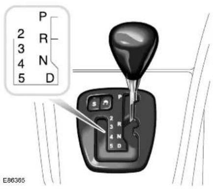
text_image
P 2 R 3 N 4 5 D S P 2 R 3 N 4 N 5 D E86365The J-gate gear selector lever is designed to accommodate two different driving techniques as follows:
- Automatic selection – the right-hand side of the selector gate.
- Manual selection – the left-hand side of the selector gate to individually select 5th, 4th, 3rd, or 2nd gear.
Gear selector positions
WARNING:
The EPB or brake pedal must be applied before selecting forward or reverse drive from a stationary position.
P = Park - Use when parking. In this position the transmission is locked. Do not select if the vehicle is moving.
N = Neutral - Disconnects the driveline from the engine. Use the EPB when stopping temporarily.
Note:
- After selecting forward or reverse drive ranges from Neutral or Park, wait briefly for the transmission to engage before accelerating.
- When in Neutral or Park the engine can only be accelerated to 4500 rev/min.
R = Reverse - Do not select if the vehicle is moving forward.
The reversing lamps come ON automatically when reverse gear is selected and the ignition switch is in position II.
D = Drive - All six gears are changed automatically as required by the throttle position and road speed.
Transmission
2, 3, 4, 5 = If selected, the transmission operates automatically in second, third, fourth or fifth gear but will not engage gears higher than the one selected.
When the vehicle is stationary the automatic gear selector may be left in D, 2, 3, 4, or 5, unless the vehicle is to be parked. When stopping for traffic lights, junctions etc., either select P or apply the EPB and select N.
Drive to fifth
When driving in gear position D with sixth gear engaged, the gear selector can be shifted sideways across the gate to 5.
Provided that the vehicle's speed is not too great, the transmission will shift down to fifth. Sixth gear will be inhibited until the gear selector is moved back to D.
Hill climbing and engine braking
When driving on roads with long downhill gradients, selecting 3 or 2 (depending on road/traffic conditions) will give engine braking.
When the gear selector is moved from D, 5, 4, or 3 down to 2, downshift to second gear will only take place at appropriate road speeds.
Reverse inhibit
Reverse is inhibited when the vehicle is moving forward at speeds above 8 km/h (5 mph).
Note: Reverse inhibit will not function in limp home mode.
Kickdown
Kickdown is operated when the pedal is pressed fully down, beyond the normal operating range and against a spring pressure, to provide maximum engine performance.
Kickdown is used in circumstances where rapid acceleration is required, such as when overtaking.
Kickdown causes the transmission to change down to the lowest gear possible to achieve maximum acceleration.
The gear engaged depends on the road speed at the time of kickdown.
As well as shifting down, the gearshift points are extended to give greater performance. This mode is in effect for as long as the pedal is pressed fully down.
Limp home mode
In the unlikely event of an electrical or mechanical failure, transmission operation will be impaired. The vehicle gear selector ranges P, R, N, D can still be used to enable the vehicle to be driven to a safe area.
The driver should be aware that the vehicle's performance will be reduced and must take this into account when driving. In this event consult a Jaguar Dealer/Authorised Repairer immediately.
Transmission
SPORT MODE

text_image
E86366The switch marked S on the J-gate surround enables the driver to select either normal N or sport S modes.
When sport mode is selected the automatic transmission will operate normally, but the gearshift points are extended to make full use of the engine's power reserves.
To select Sport, press the switch. A red indicator within the switch is illuminated to indicate that sport mode has been selected.
To cancel Sport, press the switch again.
Note: Both sides of the J-gate can be used, irrespective of transmission mode. For example, with S selected, the transmission can be operated in full automatic mode or by manual selection.
In addition to the switched transmission modes (N and S) the transmission control module will select shift patterns to suit specific conditions.
Cruise Control
When cruise control is operating at set speed the transmission selects a shift pattern to suit cruise control operation.
Dynamic Stability Control (DSC)
When DSC is switched ON and the system is activated, the transmission selects a shift pattern to suit traction control conditions.
Gradients
When the vehicle is being driven on roads with uphill gradients, the transmission adapts the shift pattern to make better use of engine power and aid engine cooling.
Note: Under the conditions previously described, the relevant transmission mode will override the N or S modes selected by the driver. When such conditions no longer exist, the transmission will revert to the shift pattern previously selected by the driver, i.e. N or S.
Cruise (Speed) Control
INTRODUCTION
The cruise (speed) control system, when fitted, can be used by the driver to maintain a selected vehicle speed above 28 km/h (17.5 mph) without the driver having to use the accelerator.
Switches on the steering wheel allow the driver manual control of the system. Brake operation also influences the cruise control system.

text_image
E86304 1 2 3 REJUMO SL1 CAMER- RESUME - to resume the set speed retained in memory.
- SET - to set the speed or increase/decrease the set speed when the speed has been set.
- CANCEL - cancels cruise control but retains the set speed in memory.
OPERATION
Setting the vehicle speed

WARNING:
Only use cruise control when conditions are favourable, for example, straight, dry, open roads with light traffic.
When you are travelling at the speed you require, which must be above 28 km/h (17.5 mph), press the SET button.
Cruise control will engage and maintain the set speed and you can remove your foot from the accelerator pedal.
Note: Cruise control will automatically disengage when the brake pedal is pressed or when the vehicle speed falls below 26 km/h (16 mph).
Changing the set speed
There are three ways to change the set speed:
- Accelerate or decelerate to the desired speed then press the SET (+) button.
- Increase or decrease the speed by pressing and holding either SET (+) or (−) until the desired speed is obtained, then release the switch.
- Increase or decrease the speed in steps of 2 km/h (1 mph) by briefly pressing either the SET (+) or (−) until the desired speed is obtained.
Resuming the set speed
If the vehicle is accelerated above the set speed, then the set speed will be resumed when the accelerator pedal is released. If CANCEL is pressed, or the brake pedal is pressed, the cruise control will disengage but the set speed memory will be retained. Press RESUME and the vehicle will return to the set speed.
Note: Cruise control will not resume at speeds below 28 km/h (17.5 mph). RESUME will not operate if the ignition has been turned off.
Cruise (Speed) Control
Caution:
- RESUME should only be used if the driver is aware of the set speed and intends to return to it.
- It is not recommended to resume set speed when a low gear is selected as excessive engine speeds will occur.
Cruise control will switch off and clear the memory when:
• The ignition is switched to position 0.
- A fault occurs. The cruise control system will switch OFF and cannot be used until the fault is cleared.
Cruise control automatic switch off
Cruise control will switch off but the set speed will remain in the memory when:
• The CANCEL button is pressed.
• The brake pedal is pressed.
• Speed falls below 26 km/h (16 mph).
- Neutral, Park or Reverse gear positions are selected.
- Dynamic Stability Control (DSC) is operating.
- The difference between the actual and set speed is too great.
- The vehicle reaches a maximum speed of 230 km/h (144 mph).
- The accelerator pedal is used to accelerate beyond the set speed for too long a period.
Adaptive Cruise Control (ACC)
natural_image
Front view illustration of a silver sedan (no text or symbols visible)E86371
The Adaptive Cruise Control system is designed to aid the driver to maintain a gap from the vehicle ahead or a set road speed if there is no slower vehicle ahead. The system is intended to provide enhanced operation of the vehicle when following other vehicles which are in the same lane and travelling in the same direction.

WARNING:
Adaptive Cruise Control is not a collision warning or avoidance system. Additionally, Adaptive Cruise Control will not react to:
• Stationary or slow moving vehicles below 10 km/h (6 mph).
- Pedestrians or objects in the roadway.
- Oncoming vehicles in the same lane.
The Adaptive Cruise Control system is based on the use of a radar sensor which projects a beam directly forward of the vehicle so as to detect objects ahead.
The radar sensor is mounted behind a cover on the left-hand side of the lower cooling aperture, to provide a clear view forward for the radar beam.
- Only use Adaptive Cruise Control when conditions are favourable, that is, straight, dry, open roads with light traffic.
- Do not use in poor visibility, specifically fog, heavy rain, spray or snow.
- Do not use on icy or slippery roads.
- It is the driver's responsibility to stay alert, drive safely and be in control of the vehicle at all times.
- Keep the front of the vehicle free from dirt, metal badges or objects, including vehicle front protectors, which may prevent the sensor from operating.
- Do not use ACC when entering or leaving a motorway.
Adaptive Cruise Control (ACC)
USING ACC
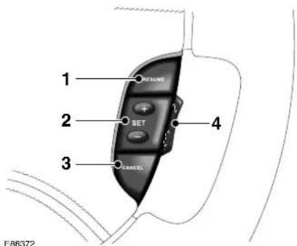
text_image
1 RESLINE 2 SET 3 CANCEL 4 E86372The system is operated by switches mounted on the steering wheel. The driver can also intervene at any time by use of the brake or accelerator pedal.
The steering wheel switches operate as follows:
- RESUME - to resume the set speed retained in memory.
- SET - to set the speed or increase/decrease the set speed when the speed has been set.
- CANCEL - cancels cruise control, but retains the set speed in memory.
- GAP - increase or decrease.
Setting the speed
Accelerate as normal until the required speed is reached.
Press the SET (+) button briefly and the vehicle speed will then be stored in the memory and the system engaged. The set speed will be displayed on the message centre.
SET SPEED
80 KM(50 MPH) (80 KM/H)
Changing the set speed
There are three ways to change the set speed:
- Accelerate or brake to the required speed and press the SET (+) button.
- Increase or decrease the speed by pressing and holding either the SET (+) or (−) button until the required set speed is shown on the message centre. The vehicle speed will gradually change to the selected speed.
- Increase or decrease the speed in steps of 2 km/h (1 mph) by briefly pressing the SET (+) or (−) button.
ACC operates between approximately 34 km/h and 180 km/h (20 mph and 110 mph) dependent on the country specification.
Set speeds outside this range will not be captured.
The ACC may apply the brakes to slow down the vehicle to the new set speed. The new set speed will be displayed on the message centre until ACC is cancelled.
Adaptive Cruise Control (ACC)
Entering the follow mode set gap

WARNING:
When in follow mode, the vehicle will not decelerate automatically to a stop, nor will the vehicle always decelerate quickly enough to avoid a collision without driver intervention.
Once a set speed has been selected, the driver can release the accelerator and the set road speed will be maintained.
When a vehicle ahead enters the same lane or a slower vehicle is ahead in the same lane, vehicle speed will be adjusted automatically until the gap to the vehicle ahead corresponds to the preset gap. The vehicle is now in follow mode.

The warning indicator in the instrument panel will be illuminated,
GAP

The message centre will display the gap set.
The vehicle will then maintain the constant time gap to the vehicle ahead until:
- The vehicle ahead accelerates to a speed above the set speed.
- The vehicle ahead moves out of lane or out of view.
• A new gap distance is set.
If necessary, the vehicle brakes will be automatically applied to slow the vehicle to maintain the gap to the vehicle in front. The maximum braking which is applied by the ACC system is limited and can be overridden by the driver applying the brakes, if required.
Note: Driver braking will cancel Adaptive Cruise Control.
If the ACC system predicts that its maximum braking level will not be sufficient, then an audible warning will sound while the ACC continues to brake.
This is accompanied by a red warning indicator and DRIVER INTERVENE will be displayed on the message centre. The driver should take IMMEDIATE action.
When in follow mode the vehicle will automatically return to the set speed when the road ahead is clear, for instance when:
- The vehicle in front accelerates or changes lane.
- The driver changes lane to either side or enters an exit lane.
The driver should intervene if appropriate.
Changing the follow mode set gap
The gap from the vehicle ahead can be decreased or increased by pressing the gap setting rocker switch on the steering wheel.
Four gaps are available and the selected gap setting will be displayed on the message centre when the rocker switch is pressed.
After the ignition is switched ON the default gap will be automatically selected ready for ACC operation.
Adaptive Cruise Control (ACC)
Note: It is the driver's responsibility to select a gap appropriate to the driving conditions.
Overriding the speed and follow mode

WARNING:
Whenever the driver is overriding the ACC by depressing the accelerator pedal, the ACC will not automatically apply the brakes to maintain separation from any vehicle ahead.
The set speed and gap can be overridden by pressing the accelerator pedal when cruising at constant speed or in follow mode.
If the vehicle is in follow mode, the instrument panel warning indicator will go out when the ACC is overridden by the driver using the accelerator and CRUISE OVERRIDE will be displayed on the message centre.
When the accelerator is released the ACC function will operate again and vehicle speed will decrease to the set speed, or a lower speed if follow mode is active.
Automatic low speed switch off
If the speed of the vehicle decreases below 30 km/h (18 mph), the ACC system will be automatically switched OFF and the instrument panel warning indicator will go out.
If the brakes were being applied by the ACC system, they will be slowly released.
This will be accompanied by an audible warning, a red warning indicator and
DRIVER INTERVENE will be displayed on the message centre. The driver must take control.
Automatic switch off
Adaptive Cruise Control will disengage, but not clear the memory when:
• The CANCEL button is pressed.
• The brake pedal is pressed.
- Neutral, Park or Reverse gear positions are selected.
• Dynamic Stability Control (DSC) activates.
Adaptive Cruise Control will disengage and clear the memory when:
• The ignition switch is switched OFF.
• Maximum vehicle speed is reached.
• A fault occurs in the ACC system.
Resuming the set speed/follow mode
Caution: RESUME should only be used if the driver is aware of the set speed and intends to return to it.
By pressing the RESUME button after ACC has been cancelled, for example, after braking, the ACC will become active again provided that the set speed memory has not been erased.
The set speed will be displayed for four seconds and the original set speed will be resumed, unless a vehicle ahead causes the follow mode to become active.
Hints on driving with ACC.
The system acts by regulating the speed of the vehicle using engine control and the brakes. Gear changes may occur in response to deceleration or acceleration whilst in ACC.
ACC is not a collision avoidance system, however, during some situations the system may provide the driver with an indication that intervention is required.
Adaptive Cruise Control (ACC)
An audible alarm will sound, accompanied by a red warning indicator and the message DRIVER INTERVENE if the ACC detects:
- That a failure has occurred whilst the system is active.
- That using maximum ACC braking only is not sufficient.
- That the vehicle speed has decreased below the minimum for ACC operation.
Note:
- Adaptive cruise control operates when the gear selector lever is in position 2, 3, 4, 5 or D.
- When engaged, the accelerator pedal rests in the raised position. Fully release the pedal to allow normal ACC operation.
Detection beam issues
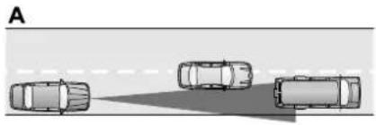
natural_image
Top-down view of three cars on a road with a spotlight, no text or symbols visible
natural_image
Diagram showing a vehicle and two mechanical components with a light beam, no text or symbols present
natural_image
Diagram showing vehicles on a curved road with a vehicle-mounted device, no text or symbols presentJOL3033
Detection issues can occur:
- When driving on a different line to the vehicle in front (A).
- With vehicles that edge into your lane which can only be detected once they have moved fully into your lane (B).
- There may be issues with the detection of vehicles when going into and coming out of a bend (C).
In these cases ACC may brake late or unexpectedly. The driver should stay alert and intervene if necessary.
Adaptive Cruise Control (ACC)
ACC malfunction
If a fault occurs during operation of the system in cruise or follow modes, the ACC system will switch OFF and cannot be used until the fault is cleared.
A red warning indicator and the message DRIVER INTERVENE appear briefly, and are then replaced by an amber warning indicator and the message CRUISE NOT AVAILABLE.
If failure of the ACC or any related system occurs at any other time, an amber warning indicator will be displayed accompanied by the message CRUISE NOT AVAILABLE. It will not be possible to activate the ACC system in any mode.
Accumulations of dirt, snow or ice on the sensor or cover may inhibit ACC operation. Fitting of a vehicle front protector or metallised badges may also affect ACC operation.
If this occurs in ACC cruise/follow mode, the red warning indicator is displayed, the audible alarm sounds and the message DRIVER INTERVENE appears briefly.
These warnings are then replaced by the amber warning indicator and the message ACC SENSOR BLOCKED is displayed. The system is no longer active.
Clearing the obstruction allows the system to return to normal operation. If the obstruction is present when ACC is inactive, e.g. on initial starting or with the ACC system switched off, the amber warning indicator will be displayed with the message ACC SENSOR BLOCKED.
Tyres other than those recommended may have different sizes. This can affect the correct operation of the ACC.
FORWARD ALERT FUNCTION
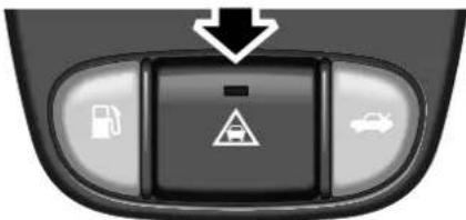
text_image
Control panel interface with icons for fuel, parking, and car, featuring a warning symbol and downward arrowE86374
Limited detection and warning of objects ahead is provided during ACC operation by the ACC DRIVER INTERVENE warning.
The forward alert feature additionally provides warnings whilst ACC is not engaged; if an object is detected close ahead then a warning tone and message will be issued. The brakes will not be applied.
This additional feature may be switched on or off using the forward alert switch in the lower outboard knee bolster switchpack. When the indicator lamp in the switch is on, forward alert is active.
The sensitivity of the warning may be changed:
- Press the gap decrease button when ACC is disengaged to display and then decreases the sensitivity of the alert.
- Press the gap increase button displays and then increases the sensitivity of the alert.
Both of these are accompanied by the FORWARD ALERT message on the message centre.
Automatic Speed Limiter
Automatic Speed Limiter (ASL) set speeds must be within local speed restriction limits. The driver must always ensure that a safe speed is set, taking into account the prevailing traffic and road conditions.
ASL can be used in a situation where varying vehicle speed is likely, but a maximum speed must not be exceeded.
For example, where a local speed limit is 80km/h (50mph), the set speed could be at that limit or just under. The driver is then safe in the knowledge that the local speed limit cannot be exceeded while ASL is operating.
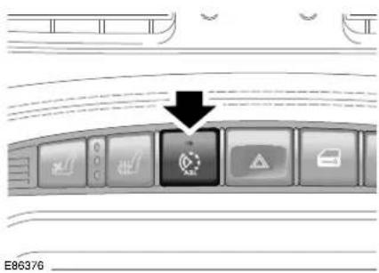
text_image
E86376The ASL button allows the driver to select between cruise control and the automatic speed limiter.
The ASL can be to any speed between 30 km/h (18 mph) to 240 km/h (150 mph).
When the ASL system is selected, the tell-tale status indicator in the switch will illuminate. When the ASL button is pressed again, the indicator will extinguish, ASL will be cancelled and cruise control will be available again.
USING THE ASL
Setting a speed limit
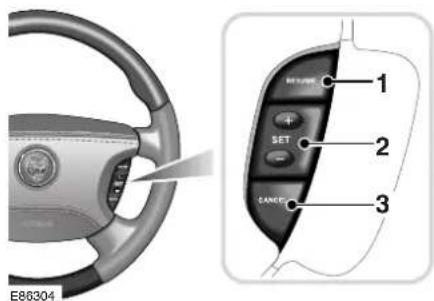
text_image
E86304 1 2 SET CANCE 3- Press the ASL button. The tell tale indicator in the switch will illuminate.
- Press the RESUME button (1). While a speed is being set or altered the message centre display will show the selected speed.
- Use the +/- buttons (2) to set the required speed.
- The set speed can be adjusted at any time by pressing the +/- buttons (2). While a speed limit is being set or altered, a message is displayed on the message centre.
Note: The message is also displayed at other times as an information display.
When ASL is selected and a set speed inserted, the engine will respond normally up to the set speed. Further accelerator pedal pressure will not increase the vehicle speed beyond your set speed.
Suspending ASL
ASL can be suspended by pressing the CANCEL button (3). Applying sudden, rapid acceleration (kickdown) will also suspend ASL.
LIMITER CANCELLED
Resuming ASL
If ASL has been suspended, it can be reinstated with a single press of the RESUME button (1), however, ASL will only reinstate if the vehicle speed is less than the current speed set in memory and greater than 30 km/h (18 mph). The message centre will display an appropriate message if the vehicle speed is too fast to resume ASL.
TOO FAST TO RESUME LIMIT
Exceeding the set speed
If the set speed is exceeded, e.g. on a steep downhill section, the message centre will display an appropriate message along with an amber warning indicator.
OVER LIMIT XXX km/h (MPH
There are three categories of over limit displays:
- If the set speed is exceeded by up to 15 km/h (9 mph), the message centre will display the message along with an amber warning indicator.
- If the set speed is exceeded by more than 15 km/h (9 mph), the message centre will display the message along with a flashing amber warning indicator.
- If the set speed is exceeded by more than 15 km/h (9 mph) for a duration of five seconds, the message centre will display the message along with a flashing amber warning indicator and also give an audible warning tone.
Use your brakes to rectify the situation.
ASL unavailable
If ASL is not available due to a fault, the message centre will display an appropriate message along with an amber warning indicator.
LIMITER NOT AVAILABLE
When the ignition is switched off, ASL is deactivated and any set speed is deleted from memory.
Stability Control
DYNAMIC STABILITY CONTROL (DSC)
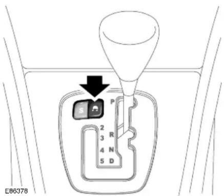
text_image
E06378Unless it has been switched off, Dynamic StabilityControl is operational whenever the engine is running. If the system is operating, the warning indicator in the instrument panel will flash.
The Dynamic Stability Control (DSC) system controls the Anti-lock Braking System (ABS), traction control and yaw control of the vehicle.
Yaw control determines the vehicle's direction relative to the driver's inputs (sideslip and under/oversteer). It applies braking pressure to individual wheels if excessive variation is detected. This ensures that the vehicle follows the driver's intended direction of travel.
Traction control will intervene to prevent wheel spin, by automatically reducing the power output from the engine and applying braking to individual wheels.
This improves acceleration, particularly on surfaces with uneven friction, for example, one wheel on ice and the other on tarmac.
ABS helps to prevent the road wheels from locking and skidding during emergency braking.
When the ABS system is operating, the warning indicator in the instrument panel will flash.
The Dynamic Stability Control system can be switched OFF by pressing the switch on the centre console switchpack. The warning indicator in the instrument panel will remain on and a message will be shown to indicate that the system has been switched OFF. If the switch is pressed again the system will switch ON. If cruise control is engaged it will automatically disengage if stability control activates.
A system malfunction is indicated by the illumination of the amber DSC warning indicator and the message DSC FAULT. It is safe to drive the vehicle but the system may not activate under wheel spin or slide conditions. Report the fault to a Jaguar Dealer/Authorised Repairer as soon as possible.
Stability Control

WARNING:
- The fact that the vehicle is fitted with Dynamic Stability Control must never allow the driver to be tempted into taking risks which could affect his/her safety or that of other road users. In all cases it remains the driver's responsibility to drive safely according to the prevailing conditions.
- It is recommended that when using snow chains, DSC should be switched OFF.
Braking System
ANTI-LOCK BRAKING SYSTEM (ABS)
This system helps to prevent the road wheels from locking and skidding during emergency braking, assisting the driver to maintain full steering and directional stability.
The factor controlling ultimate stopping distance and cornering ability is tyre/road adhesion.

WARNING:
The fact that a vehicle is fitted with ABS must never allow the driver to be tempted into taking risks which could affect his/her safety or that of other road users.

WARNING:
The addition of ABS cannot overcome the consequences of trying to stop in too short a distance or cornering at too high a speed, or the risk of aquaplaning.

WARNING:
The driver should always take road conditions into account.
A slippery road surface always requires more braking distance for a given speed, even with ABS.
A possible increase in stopping distance compared to locked wheels may occur during ABS operation on slushy snow, gravel, sand, or some heavily corrugated or ridged warning sections of road surfaces.
ABS optimises tyre/road adhesion under maximum braking conditions though it cannot provide increased cornering ability. There is no need for special braking techniques, such as pumping the brakes, to achieve optimum braking distances and control on poor or slippery road surfaces. Tyres must be in good condition to achieve maximum adhesion.
During normal braking the ABS will not be activated. However, if the braking force applied begins to exceed tyre/road adhesion the ABS will automatically activate, preventing the road wheels from locking.
In these circumstances a pulsating effect will be felt from the brake pedal indicating that the system is functioning.
The pulsating effect is due to small fluctuations in pressure supplied to the brakes by the system to maintain full tyre/road adhesion.
Under severe braking on some road surfaces tyre noise may be apparent even though the wheels will at no time become locked.
ABS MONITORING
The ABS control module monitors the ABS electrical system from ignition switch ON to ignition switch OFF.
Any malfunction will be indicated by the anti-lock warning indicator coming on.
Should a fault develop in the ABS system, the brake system will still operate conventionally and with the same standard of performance as vehicles not equipped with ABS.
Braking System
Hints on driving with ABS
The Anti-lock Brake System (ABS) helps the driver to maintain full steering and directional stability during emergency braking by preventing the road wheels from locking and skidding. ABS constantly monitors the speed of each road wheel and varies brake pressure to each, according to the available grip. ABS optimizes the tyre-to-road adhesion under maximum braking.
When ABS is activated, you will feel a pulsating effect on the brake pedal. This is normal and you must maintain maximum pressure on the brake pedal for ABS to be effective.
ABS will enable you to steer around obstacles during emergency braking. ABS will not eliminate the dangers inherent when:
- driving too close to the vehicle in front of you
- aquaplaning
• cornering with excessive speed
• poor road surfaces.
Anti-lock Brake System (ABS) warning indicator

WARNING:
If the ABS warning indicator illuminates whilst driving, avoid heavy braking. Seek qualified assistance as soon as possible. Failure to follow this instruction may lead to personal injury or loss of vehicle control.
If a fault is detected in the ABS, the ABS warning indicator will illuminate. Drive with care if the ABS warning indicator illuminates or remains on after the bulb check cycle. The brake system will continue to function normally, but without ABS braking.
EMERGENCY BRAKE ASSIST (EBA)
The EBA system measures the rate at which the brake pressure increases. If the system detects an emergency braking situation, EBA automatically initiates the full braking effect. This can reduce stopping distances in critical situations, which can help an inexperienced driver to stop in the same distance as an experienced driver.

WARNING:
The EBA system is an additional safety system: it is not intended to relieve the driver of his responsibility for exercising due care and attention when driving.
Suspension
AIR SUSPENSION
This vehicle is fitted with a fully automatic air suspension system. It ensures that the vehicle is always at the correct ride height with varying load conditions, including luggage compartment load or when towing.
The system will automatically adjust the amount of air in the springs to level the vehicle. Air is supplied either from an air reservoir or a compressor. The compressor will run periodically to refill the reservoir.
Changes in ambient temperature will also have an effect on vehicle height when the vehicle is parked.
Caution:
- Do not overload the vehicle. Vehicle load weights are shown on page 248.
- A slight air loss is expected over time causing the vehicle to lower, so do not store or place anything under the vehicle if it is to be left for an extended period.
Speed lowering
When driving at motorway speeds, the system will lower the vehicle to improve aerodynamics and vehicle stability. The suspension will automatically return the vehicle to the normal height when the vehicle slows.
Changes in ambient temperature will also have an effect on vehicle height when the vehicle is parked.
Speed lowering is undesirable when towing. Only Jaguar approved towing equipment will not allow this feature.
Warning messages
If the message VEHICLE TOO LOW is displayed when the ignition is switched on, start the engine and wait for the suspension to raise. The vehicle should not be driven until the message is cleared.
If the message VEHICLE TOO LOW is displayed when driving, restrict the vehicle speed and wait for the system to regain the correct height and the message will then clear. If the message is displayed frequently, inform your Dealer/Authorised Repairer to have the system attended to.
If the message AIR SUSPENSION
FAULT is displayed at any time, drive with caution. Have the vehicle checked by a Dealer/Authorised Repairer at the earliest opportunity.
Note: If your vehicle needs to be recovered by a roadside emergency service ensure that the vehicle is securely lashed by the wheels and NOT the body.
Driving Information
Before driving off, check the gauges and warning indicators and messages. Take special note of any warning indicator that is on.

WARNING:
Ensure the EPB is on and the automatic gear selector is in P or N before attempting to start the engine.
Seat belts are provided for your safety and it is unwise, and in certain countries illegal, to commence any journey, however short, without wearing them.
DRIVING TIPS
Engine Braking on Downhill Gradients
When driving on mountain roads with long downhill gradients it is advisable to select a low gear.
Use Of Headlamps In Daylight
When visibility is poor the headlamps with low beam setting should be switched on so that the vehicle may be seen more easily by other road users. The instrument illumination dimmer control adjusts the brightness of the panel illumination.
Parking the Vehicle
When leaving the vehicle, remember the following:
- Whenever the vehicle is being parked, apply the EPB and move the gear selector to Park P.
- Do not leave children or pets in the vehicle unattended.
-
Do not leave luggage or valuables on view. Always take your valuables with you or lock them in the luggage compartment.
-
Remove the ignition key and spare keys, even when the vehicle is in your garage.
- When the vehicle is unoccupied, close all windows and lock all doors securely.
- Park the vehicle where it can be seen. At night, park in a well-lit area.
- When leaving the vehicle unattended, for maximum security ensure that the doors are double-locked (where fitted).
- Ensure that the keys and the key transmitters are removed from the vehicle before locking the doors, and that all doors, the luggage compartment and the bonnet are closed.
Driving Information
WINTER DRIVING
Freeing a frozen door lock
Caution: Do not apply a proprietary lock de-icer through the keyhole.
Should the lock become frozen, warm the end of the key before use.
Windscreen wiper blades
Before driving away, clear any ice from the windscreen and check that the wiper blades are free. Switching on the heated screen will accelerate this process.
Frost precautions
The correct concentration of coolant must be maintained at all times when topping up or refilling the cooling system.
TOURING
Foreign travel
Before planning foreign travel, check with a motoring organisation to ensure that your vehicle will comply with legal requirements of the countries you intend to visit.
International motoring organisations are helpful for all aspects of long distance touring advice.
In some countries it is a legal requirement to carry spare vehicle bulbs.
First aid kit
A first aid kit is compulsory equipment in certain countries. Your Jaguar Dealer/Authorised Repairer can supply a first aid kit.
Petroleum spirit in containers
Some countries forbid the carrying of petrol in containers, as do most ferry and hovercraft operators.
Cellular radio telephones
Ask your motoring organisation about the use of cellular radio telephones before travelling abroad, as some countries exercise controls on the importation and use of such equipment.
Roof rack
Only the Jaguar approved roof rack should be used, (see page 248 for load weight details).
The maximum load, including the weight of the rack, must not exceed the load rating indicated on the roof rack bars and must be deducted from the vehicle maximum luggage load.
Loads on the roof rack may affect vehicle handling, especially in crosswinds or when cornering.
Driving Information
Jaguar warning triangle
A warning triangle to give traffic advanced notice of a disabled vehicle is compulsory in many countries.
A triangle, designed to international standards, is fitted as standard equipment in certain countries.
Hazard warning lamps must be used with the warning triangle.
The warning triangle, with its stand legs folded flat, is mounted on the inside of the luggage compartment lid.
In an emergency, remove the triangle and unfold its stand legs. Place the triangle in the road in accordance with local traffic regulations to give oncoming traffic warning of an immobilised vehicle.
Driving Information
TOWING A CARAVAN OR TRAILER
Your Jaguar Dealer/Authorised Repairer, and the main motoring and caravanning organisations can advise you on towing, towing weight capacities and about regulations that apply in other countries.
The following are important points of safety, stability and comfort upon which further advice should be sought:
- Maximum braked towing weight is permissible, provided long periods of uphill driving on gradients over 8% are not undertaken.
- In high altitude mountainous regions, the thinner atmosphere can reduce engine performance.
Above 1000 metres (3280 feet) the stipulated maximum permitted gross train weight must be reduced by 10% for every 1000 metres (3280 feet) in altitude. - The kerbside weight of the vehicle can be found in the Specifications Section, page 245, of this Handbook.
- When towing at the maximum permissible rear axle load keep within legal towing speeds.
- Tyres must be inflated to the normal (higher) pressures shown on the tyre pressure label on the fuel filler flap.
-
The recommended maximum tow ball nose weight is shown in the Specifications Section, page 248, of this Handbook. Having a lower nose weight or exceeding the maximum nose weight limit may impair the vehicle's handling.
-
When towing, the nose weight of the caravan or trailer and the tow bar assembly must be deducted from the permissible maximum load, see the Specifications Section, page 248, of this Handbook.
- Avoid heavy braking. As the overrun brake on the caravan or trailer is not connected to the ABS, heavy caravan or trailer braking could critically affect the stability of the outfit as a whole.
- Ensure that the towing vehicle's engine, transmission, suspension, brakes and tyres are fully efficient and regularly serviced. Similarly check the wheels, tyres, brakes and wheel bearings of the caravan or trailer.
Caution:
- When not in use, it is recommended that the removable tow ball is either securely stowed in the luggage compartment or, preferably, not in the vehicle. Do not leave it loose in the vehicle.
- It is essential that only a Jaguar tow bar and Jaguar electrical tow bar kit are supplied and fitted by a Jaguar Dealer/Authorised Repairer. This is particularly important with this vehicle having air suspension. If unapproved towing equipment is used whilst towing, the air suspension speed lowering function will not be inhibited. This may result in a change in trailer weight distribution and attitude.
Driving Information
Tow bar Fixing Points

text_image
Diagram showing car interior components with labeled parts A, B, and C, including a close-up of the dashboard and side view.E86386
The mounting points (A) require drilling for tow bar mountings.
Tow ball centre height from the ground at Gross Vehicle Weight (GVW) (B) = 385 mm (15.157 inches).
Tow ball centre distance from bumper cover (C) = 76 mm (3 inches).
Note: This vehicle has an aluminium body, any part drilled, and any fixings attached, must be specially protected to prevent body corrosion. For further information please contact your Dealer/Authorised Repairer.
Caution: Contact your Jaguar Dealer/Authorised Repairer for details of additional parts that are advised to be fitted before towing. This is particularly important with this vehicle having air suspension. If unapproved towing equipment is used whilst towing, the air suspension speed lowering function will not be inhibited. This may result in a change in trailer weight distribution and attitude.
Fuel and Refuelling
REFUELLING
Before refuelling, switch off the ignition and remove the key.
Note: Do not leave the ignition key in the vehicle; vehicles have been stolen from garage service/filling stations whilst the driver is absent from the vehicle. It is recommended that the vehicle is locked, if left unattended.
Caution: No additives of any kind (fuel or oil) must be put into the fuel tank. Additives could reduce engine life or affect exhaust emissions.

WARNING:
- Fuel vapour is highly flammable and in confined spaces is explosive and toxic. In the event of inadvertent spillage, and before refuelling, always switch OFF the engine. Do not use exposed flame or light. Do not smoke. Do not inhale fumes.
- Do not fill the tank so that fuel is visible in the fuel filler intake tube. This could cause spillage and danger from exposed fuel.
Filling the Fuel Tank
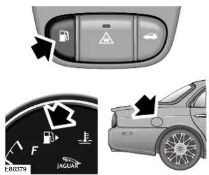
The fuel filler flap release switch is located in the knee bolster switchpack below the facia. The filler flap is on the right-hand side of the vehicle.
A small arrow is shown on the fuel gauge as a reminder on which side of the vehicle the fuel filler flap is located.
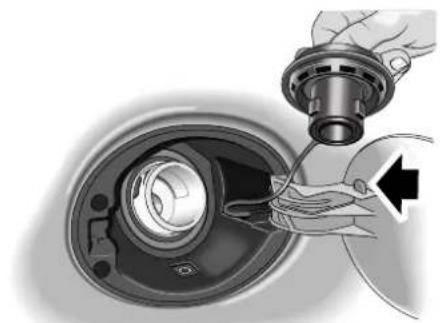
natural_image
Close-up of a hand holding a mechanical component with a cable inserted, showing internal components (no text or symbols visible)E86380
Open the fuel filler flap and turn the filler cap anti-clockwise, an 1/8 turn, and remove the cap from the filler neck. The cap is held by a retaining strap and can be stowed over the hook on the flap to allow easy access to fill the tank.
Fuel and Refuelling
A warning label on the inside of the fuel filler flap advises type/grade of fuel.
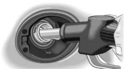
natural_image
Close-up of a mechanical component with a shaft and housing, no visible text or symbolsE86391
When filling, the dispenser nozzle must be inserted into the filler neck sufficiently to open the trap door for fuel to flow into the fuel tank. For quickness and to completely fill the tank, ensure that the fuel nozzle rests on the filler neck as shown. Fill the tank until the filler nozzle automatically shuts off. Filling beyond this point could result in fuel spillage.
After refuelling, twist the filler cap clockwise until it clicks and close the flap, which automatically locks shut.
The continuous use of high quality fuel makes the need for additional additives unnecessary.
This will help to protect the engine components against corrosion, carbon deposit formation and prevent the fuel injection system from clogging.
If in doubt your local Jaguar Dealer/Authorised Repairer will advise on which fuel must be used in your vehicle.
The filler neck of the fuel tank in a petrol vehicle is a small diameter to suit the unleaded fuel pump nozzle and will prevent the larger diameter leaded fuel nozzle from entering the filler neck.
Not all countries have a small diameter nozzle so care must be taken to only fill the petrol tank with unleaded fuel.
FUEL CAPACITY
Avoid the risk of running out of fuel and never intentionally drive the car when the fuel gauge indicates that the tank is empty. When refuelling your vehicle after the fuel gauge reads empty, you may not be able to add the fuel quantity shown below to the tank as there will be a small reserve remaining in the tank.
| Fuel tank capacity 85 litres | 18.7 gallons |
| Fill capacity (when the fuel gauge indicates empty) | 79 litres17.4 gallons |
| Reserve capacity (when the fuel gauge indicates empty) | 5.8 litres1.3 gallons |
Fuel and Refuelling
FUEL ECONOMY
The following tips not only lead to greater fuel economy but also reduce air pollution causing less environmental damage:
- Try to avoid using the car for short journeys - this will lead to greater fuel economy and reduce wear on the engine.
- Plan ahead - choose uncongested routes, combine car trips and share cars where possible.
- Drive off as soon as possible after starting a cold engine - do not leave the engine idling until it has warmed up.
- Drive smoothly and efficiently - harsh acceleration and heavy braking have a significant effect on fuel consumption - driving more smoothly saves fuel.
- Slow down - driving at high speeds significantly increases fuel consumption.
- Switch off - sitting stationary is zero miles per gallon, switch off the engine when it is safe to do so.
- Unnecessary weight - do not carry unnecessary weight and remove roof racks when not in use.
- Regular servicing keeps the engine at best efficiency.
- Ensure that tyres are inflated to the correct pressure for the journey.
- Use air conditioning and all vehicle electrical devices sparingly - all increase fuel consumption.
- Check your fuel consumption - it will help you get the most from your car and any significant change in consumption may indicate a vehicle fault.
FUEL REQUIREMENTS - PETROL ENGINES
All petrol vehicles are fitted with a catalytic system and can only use unleaded fuel.
Unleaded fuel must be used for the emission control system to operate properly. Its use will also reduce spark plug fouling, exhaust system corrosion and engine oil deterioration.
The preferred fuel should have an octane rating of at least 95 RON (Research Octane Number).
Super Green Plus 98 RON unleaded fuel (where available) may be used as an alternative to the standard 95 RON unleaded fuel.
Some countries have only 91 RON fuel available. The vehicles in these countries are specially calibrated to use this fuel.
Using unleaded fuel with an octane rating lower than recommended can cause persistent, heavy spark knock (a metallic rapping noise). If severe, this can lead to engine damage.
If a heavy spark knock is detected even when using fuel of the recommended octane rating, or if you hear steady spark knock while holding a steady speed on level roads consult a Jaguar
Dealer/Authorised Repairer to have the problem corrected.
Fuel and Refuelling
Failure to do so is misuse of the vehicle, for which Jaguar Cars Limited is not responsible. However, occasional light spark knock for a short time while accelerating or driving up hill, may occur.
Fuels containing alcohol
Caution: Take care not to spill fuel during refuelling. Fuel containing alcohol can cause paint damage, which may not be covered under the warranty.
Some fuel suppliers sell fuel containing alcohol without advertising its presence. Where uncertainty exists check with the service station operator.
Note: Some difficulty in starting may be encountered when using alcohol blended fuel.
Ethanol
Caution: This vehicle is not suitable for use with fuels containing more than 10 per cent ethanol. Do not use E85 fuels (85 per cent ethanol content).
Equipment necessary for use of fuels containing more than 10 per cent is not fitted to this vehicle. If E85 fuels are used, serious engine and fuel system damage will occur.
Fuels containing up to 10 per cent ethanol (grain alcohol) may be used. Ensure the fuel has octane ratings no lower than those recommended for unleaded fuel. Most drivers will not notice any operating difference with fuel containing ethanol. If a difference is detected, the use of conventional unleaded fuel should be resumed.
Methanol
Some fuels contain methanol (methyl or wood alcohol). If you use fuels containing methanol the fuels must also contain co-solvents and corrosion inhibitors for methanol. Also, do not use fuels that contain more than three per cent methanol even if they contain co-solvents and corrosion inhibitors. Fuel system damage or vehicle performance problems resulting from the use of such fuels is not the responsibility of Jaguar Cars Limited, and may not be covered under the warranty.
Methyl Tertiary Butyl Ether (MTBE)
Unleaded fuel containing an oxygenate known as MTBE can be used provided the ratio of MTBE to conventional fuel does not exceed 15 per cent.
MTBE is an ether based compound, derived from petroleum, which has been specified by several refiners as the substance to enhance the octane rating of fuel.
FUEL REQUIREMENTS - DIESEL ENGINES
Use only high quality diesel fuel according to specification EN 590 or equivalent.
Caution: Do not use RME (bio diesel) except in the case of those proprietary diesel fuels which contain a mix of up to 5%. Jaguar can accept no responsibility for damage caused by using RME in concentrations greater than 5%.
Prolonged use of additives is not recommended. Do not add kerosene/paraffin or petrol to diesel fuels.
Fuel and Refuelling
Caution: If you inadvertently fill your vehicle with petrol instead of diesel, do not attempt to start the engine. Contact your Jaguar Dealer/ Authorised Repairer immediately. Attempting to start the engine with petrol in the fuel tank will cause extensive damage to the engine and fuel system, which will not be covered by your Jaguar warranty. Jaguar Cars Limited can accept no responsibility for any damage caused by running your vehicle with petrol or vegetable oil in the fuel tank.
Winter grade diesel fuel
To ensure reliable diesel engine operation during cold seasonal periods, Winter grade fuel must be used. This fuel is normally available from fuel retailers during these periods and the fuel companies adjust the fuel quality to suit climatic conditions.
If the vehicle is not filled with Winter grade diesel fuel, it is recommended that the engine is idled for a period of over two minutes after starting to prevent fuel solidification during operation.
Caution: If your vehicle is fitted with a Diesel Particulate Filter (DPF) the maximum Sulphur content must not exceed 0.005%. Using an incorrect fuel will cause serious damage to the DPF.
DIESEL PARTICLE FILTER (DIESEL MODELS ONLY)
Diesel vehicles are fitted with a Diesel Particle Filter (DPF) which results in additional effective exhaust emission purification. When the engine is at its normal operating temperature and the vehicle is driven at moderate speeds, 48 km/h (30 mph), or more, a regeneration of the DPF takes place automatically. This means that the exhaust particles collected in the filter are burned away and the filter is emptied.
Message centre warnings
When DPF regeneration has not been possible due to a long period of unfavourable driving conditions, a warning message DPF FULL SEE HANDBOOK plus either a RED or AMBER priority warning indicator is displayed on the message centre, see page 97.
Red priority: If the warning message with the RED priority warning indicator is displayed, a Jaguar Dealer/Authorised Repairer must be contacted as soon as possible before damage to the DPF occurs.
Amber priority: When the message is displayed with an AMBER priority warning indicator, regeneration of the DPF is required.
To carry out DPF regeneration
- To start regeneration of the DPF, drive the vehicle, preferably on a main road or motorway, until the engine reaches its normal operating temperature.
Fuel and Refuelling
- The vehicle should then be driven for approximately a further 20 minutes, preferably at a speed of 48 km/h (30 mph) or more, but always observing speed limits and road conditions.
- Successful regeneration of the DPF is indicated by the warning message and AMBER priority warning indicator being extinguished from the message centre.
Caution: If the vehicle is frequently driven for short distances or at speeds below 48 km/h (30 mph) for long periods, especially in cold weather conditions, the engine and exhaust system does not reach normal operating temperatures. This means that the regeneration of the DPF may be required to be carried out occasionally in order to avoid impaired function of the filter.
Caution: The regeneration procedure produces high temperatures in the DPF. Heat can be felt radiating from beneath the vehicle, which is normal and not a cause for concern. However, the vehicle should not be parked over combustible material, particularly during dry weather. The heat generated could be sufficient to start a fire when in close proximity to combustible material such as long dry grass, paper etc.
RUNNING OUT OF FUEL (Diesel Models only)
Vehicles with diesel engines are equipped with a system to prevent the fuel tank from emptying completely. When the fuel reaches a minimum level, the system will activate a reduced power mode (i.e. the engine will not run properly). This will be followed by the engine stopping in approximately 1.6 km (1.0 mile).
This feature prevents the fuel system from running dry, which could cause damage to the vehicle. If the gauge indicates low fuel or the warning indicator illuminates, the fuel tank should be refuelled as soon as possible at the next filling station with at least 4 litres (0.87 gallons) of fuel.
If the system protection function has activated, the vehicle must firstly be refuelled, then restarted using the following procedure:
- Crank the engine for five seconds, then return the ignition key to position 0 (OFF).
- Turn the ignition key to position II (ON). Crank the engine. The engine should start within approximately five seconds.
Note: If the engine does not start, pause for ten seconds, with the ignition key in the 0 position (OFF), before repeating the procedure from the beginning.
Fuel and Refuelling
FUEL FILLER FLAP MANUAL
RELEASE

natural_image
Interior view of a car showing the dashboard and steering wheel (no text or symbols visible)If the fuel filler flap fails to release it can be manually unlocked as follows:
In the luggage compartment, remove the carpet from the right-hand side by turning the carpet securing screws anti-clockwise, then gently pull the carpet down.

natural_image
Illustration of a mechanical device with directional arrows and a circular component (no text or symbols)JAG0643
Locate the fuel flap release mechanism and pull the knob rearwards. This will release the flap to gain access to the filler cap and enable the vehicle to be refuelled.
Report the fault to a Jaguar
Dealer/Authorised Repairer.
Fuel and Refuelling
CATALYTIC CONVERTERS AND DIESEL PARTICULATE FILTERS
A few precautions on the use of vehicles fitted with catalytic converters and Diesel Particulate Filters (DPF) are necessary. These are:
- In order to maintain the efficiency of the emission control system it is essential that the correct fuel is used. If the vehicle is fitted with a petrol engine, never refuel with leaded fuel as this will seriously damage the catalytic converters. If the vehicle is fitted with a diesel engine, use only high quality diesel fuel to specification EN 590 or equivalent.
- Heavy impact on the converter and DPF casings must be avoided.
- The engine settings must not be altered; they have been established to ensure that the vehicle will comply with stringent exhaust emission regulations. Incorrect engine settings could cause unusually high catalytic converter and DPF temperatures and thus result in damage to the converter, DPF and vehicle. If adjustment to the settings is considered necessary, this should be performed by a Jaguar Dealer/Authorised Repairer.
-
A correctly tuned engine optimises exhaust emissions, performance and fuel economy and it is recommended that the vehicle is regularly maintained.
-
Do not continue to operate the vehicle if any engine malfunction is evident; malfunctions should be rectified immediately. For instance, misfire, loss of engine performance, excessive oil consumption or engine run-on may lead to unusually high catalytic converter temperatures and may result in damage to the converters and vehicle.
- The use of catalytic converters increases exhaust system temperatures, therefore, do not operate or park the vehicle in areas where combustible materials, such as dry grass or leaves may come into contact with the exhaust system.
- Do not run a petrol engine with either a spark plug lead disconnected or a spark plug removed. Do not use any device that requires an insert into a spark plug hole in order to generate air pressure e.g. tyre pump, paint spray attachment etc., as this could also result in catalytic converter damage.
- The vehicle is designed for normal road use. Below are examples of abuse which could damage the catalytic converters and/or vehicle and may lead to a dangerous condition due to excessively high catalytic converter temperatures:
- Competition or off-road use.
- Excessive engine speed.
- Overloading the vehicle.
- Switching off the engine whilst in gear.
Climate Control
INTRODUCTION
The cabin is supplied with filtered air from a fully automatic electronic climate control system with manual overrides.
Two systems are available:
- A two zone system which allows the front occupants to set individual temperatures for the left and right sides of the interior.
- A four zone system which allows front and rear occupants to set individual temperatures, i.e. two front zones and two rear zones.
Occupant controls
Note: If your vehicle is equipped with a touch-screen, the climate controls are described in the touch-screen display handbook.
The main climate control panel is located in the centre console above the radio and audio controls.
There are two types of control panel for either two or four zone systems:
- A dedicated control panel with LCD (Liquid Crystal Display) screen.
- A multi-function touch-control and display unit shared with navigation and other systems. Where this control unit is fitted, refer to the touch-screen display handbook for the detailed operating instructions.
Where the four zone climate control system is fitted, an additional control/display panel for rear passenger use is located at the rear of the centre console, between the front seats.
Voice control
The climate control system may also be operated by spoken commands if the optional voice activation system is fitted. For full information on the use of this system refer to the touch-screen display handbook or audio systems handbook.
RECOMMENDED OPERATION
Automatic climate control
Automatic climate control provides efficient regulation of the vehicle environment without constant adjustments from the occupant.
Sensors inside the vehicle monitor temperature, humidity and direct sunlight. In response, the electronic control system automatically adjusts the heat input, blower speed, air intake and airflow distribution, so as to maintain the selected temperature(s) and reduce misting.
Automatic operation provides optimum comfort under most driving conditions.
It is recommended that automatic control (AUTO) is selected as the normal operating mode.
Use of air conditioning
Air conditioning is an integral part of the climate control system, providing cooled and dehumidified air for occupant comfort; the dry airflow is also effective in preventing misting of the windows.
While the air conditioner can be manually switched off, it is recommended that it is used in all climatic conditions throughout the year, preferably in AUTO mode.
Close all windows and the sunroof when the air conditioning is on to ensure satisfactory operation.
Climate Control
Use of air recirculation
The air conditioner/heater system is supplied with fresh air via an intake flap.
Closing the flap causes the air inside the vehicle to be recirculated. This helps to prevent unpleasant odours from being drawn into the vehicle and also to improve the performance of the air conditioner in very hot conditions. However, the use of recirculated air will cause screen misting after a short period and should only be used as necessary.
In AUTO mode, the air intake flap is controlled automatically. If required, air recirculation may be manually selected for either a short or indefinite period.

WARNING:
To prevent humidity build up inside the vehicle and possible screen misting, avoid driving with the air conditioning system off or with manual air recirculation selected for prolonged periods.
GENERAL POINTS
To ensure the satisfactory operation of the climate control system, note the following points:
- Ensure that the external grille at the base of the windscreen, which provides fresh air for the climate control system, is kept clear of leaves, snow or obstructions.
-
A solar sensor, see item 1 on the next page, is mounted on the centre top of the facia. Ensure that this sensor is not covered.
-
Temperature and humidity sensors, see item 2 on the next page, are located behind the small grille. Do not cover or obstruct the opening.
- Air ducts under the front seats supply the rear passenger footwells (see air distribution illustration). Objects or material placed under the seats may block or obstruct the open ducts.
- The external air intake to the air conditioner/heater system is fitted with a filter. Ensure that the filter is changed at the specified service intervals to maintain efficient operation.
- If the air conditioning system is not used frequently, it should be run briefly at least once each week, with a cold setting, to prevent the seals from drying out with subsequent refrigerant leaks.
- Moisture removed from the air by the air conditioning unit is discharged onto the road underneath the vehicle. After stopping, puddles of water may form underneath the vehicle.
Climate Control
AIR DISTRIBUTION
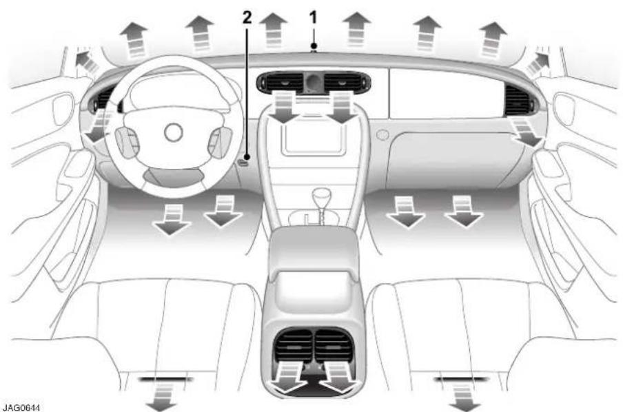
text_image
2 1 JAG0644- Solar sensor.
- Temperature and humidity sensors.
The illustration above shows the location of the air vents within the vehicle. The airflow from the facia face level vents is regulated using thumbwheel controls and adjustable direction vanes.
Air distribution between the windscreen, facia and floor levels is selected automatically when operating in AUTO mode, but can be selected manually.
AUXILIARY FUEL-FIRED HEATER - DIESEL ONLY
The auxiliary heater aids in warming the engine and interior compartment. It is integrated into the cooling system and is automatically switched on or off depending on the coolant and ambient temperature, while the engine is running.
It is possible that when the fuel-fired heater is activated, vapour may appear from under the front of the vehicle for a short time during which a slight odour may be detected. This is normal.
Note: The auxiliary heater will not function if the climate control is switched off.
Front Climate Controls
FRONT CONTROL PANEL
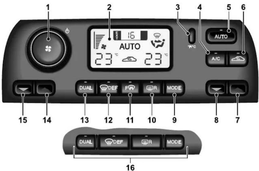
text_image
1 2 3 4 5 6 AUTO 23 °C 23 °C A/C DUAL DEF FW QR MODE 15 14 13 12 11 10 9 8 7 DUAL DEF QR MODE 16JAG0645
- Blower speed and system On/Off.
- Display panel.
- Fahrenheit/Celsius selector.
- Air conditioner on/off.
- Select automatic operation.
- Recirculation/fresh air.
- Increase right zone temperature.
- Decrease right zone temperature.
- Select air distribution.
- Heated rear screen/door mirrors.
- Heated front screen (optional).
- Defrost windows.
- Select dual/single temperature zone.
- Increase left zone temperature.
- Decrease left zone temperature.
- Option without front screen heater.
The climate control functions are selected by push buttons and a rotary control.
When a button is pressed, selection of the function is confirmed by a beep; most buttons also have an illuminated LED.
Many system functions also have graphic symbols displayed on the LCD (Liquid Crystal Display) screen.
Automatic control (AUTO) may be overridden at any time. Defrost/demist operation is available and also manual selection of blower speed, air distribution, recirculation, air conditioning and windscreen heating.
Panel illumination
With the exterior lighting switched on, the graphics on the panel controls are illuminated by low level backlighting.
Front Climate Controls
The illumination level is adjusted by the common instrument panel dimmer control (see page 115).
TO SWITCH THE SYSTEM ON
The climate control system operates in position II of the ignition switch.
With the ignition key turned to the run position, the system will switch on in the operating mode last set.
For normal usage select AUTO mode.
AUTO mode
Automatic operation provides a controlled environment over a temperature range of 17^ C to 31^ C ( 61^ F to 89^ F) and should be regarded as the normal operating mode.
To select automatic climate control press the AUTO button; the word AUTO
appears on the LCD screen to confirm selection.
Front and rear screen heating and timed air recirculation may be selected in AUTO mode. Selecting any other control will cancel AUTO operation.
Automatic operation cannot be deselected using the AUTO button. To exit AUTO mode, select another mode or press the blower control knob to switch the system off.
Temperature selection


Separate controls allow the driver and front passenger zone
temperatures to be independently adjusted. Press the red buttons to increase temperature and the blue buttons to decrease temperature.
Both driver and front passenger selected temperatures are always displayed.
Pressing the driver's buttons to select the maximum or minimum temperature settings causes the display to change to HI or LO respectively and cancel AUTO mode.
To quickly jump from HI or LO to a convenient midrange temperature of 23^ C ( 73^ F), press and hold AUTO for a few seconds.
Dual temperature zones

With the DUAL button LED illuminated, the system provides separate temperature control of
the driver and front passenger zones.
Press DUAL to deselect dual temperature control (LED off); the front passenger temperature will change to that of the driver side. Using the driver side temperature control buttons will now change both zone temperatures together.
To select dual temperature control, press either the DUAL button or one of the front passenger side red/blue temperature control buttons. The DUAL LED is illuminated.
External temperature
The external (EXT) temperature is displayed at the top of the screen.

Press the button to change the scale between degrees Fahrenheit (°F) and degrees Celsius (°C) for the displayed
internal and external (EXT) temperatures.
Front Climate Controls
Windscreen defrost/demist
Frost and heavy misting

To remove frost or heavy misting from the windscreen, press the DEF button.
- The blower switches on automatically at a high speed, but the speed can be increased or decreased manually if required.
- Air conditioning switches on automatically and cannot be deselected.
- Recirculation is cancelled and cannot be selected.
- The front screen heater and the rear screen heater/door mirror heaters switch on automatically, provided the engine is running.
To deselect defrost mode, press AUTO (recommended operating mode).
Light misting

To prevent or remove light windscreen misting, select manual air distribution to
windscreen and feet.
Heated screens and door mirrors


The front (F) and rear (R) screen heaters may be switched on and off in
any mode, including system off, but only operate when the engine is running. The door mirror heaters are also controlled by the rear screen heater button.
The front screen heater (if fitted) switches off automatically after 6½ minutes. The rear screen and door mirror heaters switch off automatically after 21 minutes.
The windscreen heaters may be manually deselected during the timed period using the push buttons.
In cold ambient conditions, at the start of a journey, the front and rear screen heaters will switch on automatically for the timed period.
Note: The top three lines of the rear screen pattern are a concealed antenna system and do not defrost the rear screen.
Air conditioning

Press to switch the air conditioning on or off.
The air conditioning system is controlled automatically in AUTO mode. Deselecting A/C cancels AUTO mode.
The air conditioning system is also switched on automatically in defrost mode (DEF) but cannot be deselected.
Blower speed

Set the blower speed as required with the rotary control knob. Blower speed is shown as a series of bars on the LCD screen.
When operating in AUTO mode, blower speed is controlled automatically (but not displayed) and any adjustment of the knob will cancel AUTO mode.
Note: In AUTO mode, the blower only operates at low speed, if heating is required, until the engine is warm.
Front Climate Controls
MANUAL AIR DISTRIBUTION
Air distribution is automatically controlled in AUTO and defrost modes.

Press MODE to select manual air distribution. Four air distribution modes are available and are selected in succession by pressing the MODE button. A symbol is displayed for the selected mode.

Airflow distributed to the windscreen and feet; select to prevent or remove light misting and when heating the interior.

Airflow directed to foot level; select to heat the interior.

Airflow distributed to the face and feet.

Airflow directed at face level only; select to cool the interior.
AIR RECIRCULATION
Timed air recirculation

Press the button briefly to select timed air recirculation. The fresh air intake is opened and the
button LED extinguished at the end of the time out period.
Latched air recirculation

Press and hold the button for a few seconds to select latched air recirculation. Selection is
indicated by the screen symbol and two beeps.
Selecting latched air recirculation cancels AUTO operation.
To deselect latched air recirculation, press the recirculation button again, or select AUTO.
TO SWITCH THE SYSTEM OFF

Press in the blower rotary control knob to switch the climate control system off.
If the blower control knob is pressed again, the system will switch on in the previous mode set.
4-Zone climate control system
If 4-zone climate control is fitted, switching off front climate control (above) will also cause the rear climate control system to be switched off. Switching the front system on again will not switch the rear system on.
RAM AIR
With the climate control system switched off, air recirculation is automatically selected (intake flap closed). To select fresh air with the system off, press the MODE button to select one of the air distribution modes.
With the blower switched off, the fresh airflow results from the forward motion of the vehicle (ram air effect).
Rear Climate Controls
CONTROL PANEL

text_image
1 2 EXT 15J AUTO 23 °C 23 °C MODE AUTO 8 E86338 345€- Blower speed and system on/off.
- Display panel.
- Increase right zone temperature.
- Decrease right zone temperature.
- Select automatic operation.
- Select air distribution.
- Increase left zone temperature.
- Decrease left zone temperature.
4-ZONE CONTROL
The rear climate control panel provides independent temperature control of the rear left and right passenger zones, when the front control system is operating.
SWITCHING ON
The rear climate control system can only be switched on if the front system is already switched on. Switching on the front system does not switch on the rear system.
To switch on the rear climate control system, press AUTO, or press in the blower control knob (1).
AUTO OPERATION
Selecting AUTO (5) provides full automatic temperature control, including blower speed and air distribution, for both rear positions.
TEMPERATURE CONTROL
The left and right zone temperatures are set independently using the red (increase temperature) and blue (decrease temperature) in the same manner as the front system.
HI/LO (maximum/minimum temperatures) cannot be selected on the rear control panel but selection of HI/LO on the front panel will apply to all four zones, overriding rear temperature selection.
MODE BUTTON
Press the MODE button (6) to select manual air distribution; repeat presses will cycle through the following options:
- Rear airflow to face level only.
- Rear airflow to face and feet levels.
• Rear airflow to feet only.
Selecting MODE will immediately cause AUTO operation to be deselected.
BLOWER SPEED
Rotate the blower speed knob (1) to vary the blower speed as indicated by the changing number of bars shown on the LCD display (2).
Adjusting the blower speed will immediately cause AUTO operation to be deselected.
Note: If defrost (DEF) is selected on the front control panel, the rear system will operate normally but with a limit on the blower speed.
Rear Climate Controls
SWITCHING OFF
The rear system may be switched off independently of the front system by pressing in the blower control knob (1).
The rear system will be switched off if the front system is switched off.
Touch-screen Climate Control
INFORMATION
A general introduction to the touch-screen is given in the
Touch-screen chapter of this handbook, starting on page 252. The operating information given here refers to the touch-screen and other controls.
The vehicle has both driver and passenger (dual zone) red and blue temperature control arrow buttons.
Refer to page 172 for more information on the rear climate control panel fitted with the optional 4-zone system.
Controls and displays
The climate control system has its own menu on the touch-screen. A number of other buttons are also used for climate control and are located around the perimeter of the touch-screen. When a perimeter button is pressed, selection of the function is confirmed by a beep and, on most buttons, illumination of a Light Emitting Diode (LED).
An LCD screen below the touch-screen shows the interior temperatures set by the driver and passenger and the external (EXT) ambient temperature.
Note: Using other systems and touch-screen displays, such as audio or navigation, does not affect the climate control settings.
Panel illumination
With the exterior lighting switched on, the graphics on the panel controls are illuminated by low level backlighting.
The illumination level is adjusted by the common instrument panel dimmer control.
Touch-screen Climate Control
CONTROLS
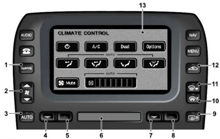
text_image
CLIMATE CONTROL AUDIO A/C Dual Options 13 NAV MENU 12 1 CLIMATE AUTO 2 Mute 11 - F 10 3 AUTO 4 5 6 7 8 9JAG0646
- Select climate control touch-screen.
- Adjust blower speed.
- Select automatic operation.
- Decrease left-hand zone temperature.
- Increase left-hand zone temperature.
- LCD screen: interior and exterior temperatures.
-
Decrease right-hand zone temperature.
-
Increase right-hand zone temperature.
- Heated rear screen/door mirrors.
- Heated front screen.
- Defrost operation.
- Select air recirculation.
- Touch-screen.
Touch-screen Climate Control
IGNITION ON
The climate control system operates in position II of the ignition switch.
When the ignition is switched to position II or the engine is started, the Jaguar logo will be displayed briefly followed by the last touch-screen selected (e.g. radio).
The climate control system will be set to the climate operating mode selected previously.
CLIMATE CONTROLS DISPLAY
There are two climate control touch-screen displays, one for the system 'ON' state and the other for system 'OFF'/ram air mode. Smaller pop-up displays appear briefly when selecting air recirculation or adjusting the blower speed.
Most climate functions can be selected using the perimeter buttons without displaying the climate touch-screen buttons.

To select the touch-screen display, press the CLIMATE button.
To exit the climate control screen, select another system function, e.g. AUDIO.
AUTO MODE
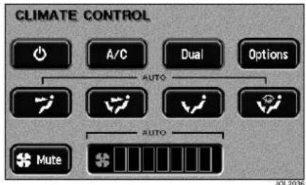
text_image
CLIMATE CONTROL A/C Dual Options AUTO AUTO MuteAutomatic operation provides a controlled environment over a temperature range of 17^ C ( 61^ F) to 31^ C ( 89^ F) and should be regarded as the normal operating mode.

To select automatic climate control press the AUTO button and select the required temperature.
The AUTO mode touch-screen is shown above. If the touch-screen is not displayed, press the CLIMATE button.
Front and rear screen heating and timed air recirculation may be selected while remaining in AUTO mode. Selecting any other climate control perimeter button or touch-screen button will cancel AUTO operation.
Automatic operation cannot be deselected using the AUTO button. To exit AUTO mode, select another climate mode or touch the system ON/OFF button to switch the system off.
Touch-screen Climate Control
TEMPERATURE SELECTION


Set the required interior temperature with the red or blue arrowed buttons.
Press the red buttons to increase temperature and the blue buttons to decrease temperature.
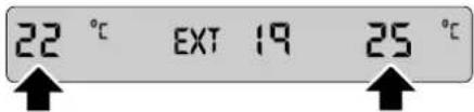
text_image
22 °C EXT 19 25 °CThe selected temperatures will appear on the LCD screen below the touch-screen.
Pressing the driver's buttons to select the maximum or minimum temperature settings causes the LCD screen to change to HI or LO respectively and cancels AUTO mode.
To quickly jump from HI or LO to a convenient mid-range temperature of 23^ C ( 73^ F), press and hold AUTO for a few seconds.
DUAL TEMPERATURE ZONES

With the Dual button illuminated, the system provides separate
temperature control of the driver and passenger zones.
Touch Dual to deselect dual temperature control; the passenger temperature will change to that of the driver's side. Using the driver's side temperature control buttons will now change both zone temperatures together.
To select dual temperature control, either touch Dual or press one of the passenger's side temperature control buttons.
EXTERNAL TEMPERATURE
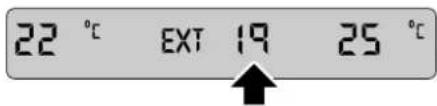
text_image
22 °C EXT 19 25 °CThe external (EXT) temperature is displayed on the LCD screen.
CELSIUS/FAHRENHEIT SELECTION

Touch the button to change the scale between degrees Celsius (°C) and degrees
Fahrenheit (°F) for the displayed interior and external temperatures.
Touch-screen Climate Control
TIMED AIR RECIRCULATION

text_image
CLIMATE CONTROL Options Mute
Press the button briefly to select air recirculation for a timed period only; the pop-up shown above
will appear for a few seconds on top of the currently selected touch-screen.
The fresh air intake is opened and the button LED extinguished at the end of the timed period.
Latched fresh air
Pressing the air recirculation button when the button LED is illuminated will cancel recirculation and allow fresh air into the vehicle.
Deselecting air recirculation cancels AUTO mode.
LATCHED AIR
RECIRCULATION
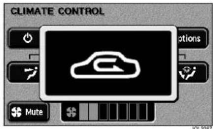
text_image
CLIMATE CONTROL Options Mute JOL2007
To latch air recirculation (so that it remains selected), press and hold the air recirculation button until
the pop-up changes from the timed to the latched recirculation symbol.
Selection is also indicated by two beeps and the button LED flashing four times then remaining illuminated.
Selecting latched recirculation cancels AUTO mode.
Caution: Prolonged operation with recirculation selected in cold, damp conditions could result in interior condensation.
Touch-screen Climate Control
WINDSCREEN DEFROST/DEMIST
Frost and heavy misting

To remove frost or heavy misting from the windscreen, press the DEF button.
- The blower switches on automatically at a high speed but the speed can be increased or decreased manually if required.
- Air conditioning switches on automatically and cannot be deselected.
- Recirculation is cancelled and cannot be selected.
- The front screen heater and the rear screen heater/door mirror heaters switch on automatically, provided the engine is running.
To deselect defrost mode, press DEF again, or press AUTO (recommended operating mode).
Light misting

To prevent or remove light windscreen misting, select manual air distribution to
windscreen and feet (see MANUAL AIR DISTRIBUTION, page 180).
HEATED SCREENS AND DOOR MIRRORS

The front screen heater (F) and the rear screen heater (R) may be switched on and off in any mode, including system off, but only operate when the engine is
running. The door mirror heaters are also controlled by the rear screen heater button.
The front screen heater (where fitted) switches off automatically after four minutes. The rear screen and door mirror heaters switch off automatically after ten minutes.
The windscreen heaters may be manually deselected during the time-out period using the buttons.
In cold ambient conditions, at the start of a journey, the front and rear screen heaters will switch on automatically for the timed period.
Where a front screen heater is not fitted, the windscreen has a wiper park zone heater which operates automatically with no manual control.
Note: The top three lines of the rear screen pattern are a concealed antenna and do not defrost the rear screen.
Touch-screen Climate Control
AIR CONDITIONING

Touch the A/C button to switch the air conditioning on or off.
The air conditioning system is controlled automatically in AUTO mode. Deselecting A/C cancels AUTO mode.
The air conditioning system is also switched on automatically in defrost mode (DEF) but cannot be deselected.
BLOWER SPEED

Set the blower speed as required using the rocker button. Blower speed is shown as a series of bars on the touch-screen.
If the blower speed is changed while a non-climate control touch-screen is displayed, a pop-up display showing the blower speed bars will appear for a short period.
When operating in AUTO mode, blower speed is controlled automatically (but not displayed) and any adjustment of the button will cancel AUTO mode.
Note: In AUTO mode, the blower will only operate at low speed until the engine is warm, if heating is required in the vehicle.
BLOWER MUTE

To reduce the interior noise level, the blower speed may be quickly reduced to a preset level by touching the Mute button.
Selecting Mute will cancel AUTO mode, but touching the Mute button again will return operation to the previous state.
When JaguarVoice is fitted, the climate control system will automatically prevent any increase in blower speed while speech commands are given.
Note: The Mute function should only be used for short periods, as it reduces the efficiency of the climate control system.
MANUAL AIR DISTRIBUTION
Air distribution is automatically controlled in AUTO and defrost modes.
Touch one of the four air distribution buttons on the screen to cancel the current mode and select manual operation.
The air distribution options are:

Airflow directed at face level only; select to cool the interior.

Airflow distributed to the face and feet.

Airflow directed to feet level; select to heat the interior.

Airflow distributed to the windscreen and feet; select to prevent or remove light misting and when heating the interior.
Touch-screen Climate Control
SWITCHING CLIMATE
CONTROL OFF
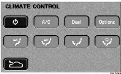
text_image
CLIMATE CONTROL A/C Dual Options
To switch the system off, touch the system ON/OFF button on the climate control screen. The touch-screen will change to the system off/ram air climate control screen above.
Pressing the system On/Off button will return the system to the previous state.
It is recommended that AUTO is selected to switch the system on again.
RAM AIR

text_image
CLIMATE CONTROL A/C Dual OptionsWith the climate control system switched off, air recirculation is automatically selected (intake flap closed).
To select fresh air with the system off, touch the ram air button (bottom left on illustration). The intake flap will open with air distribution to face level automatically selected.
Any of the other air distribution modes may be selected manually using the touch-screen.
With the blower switched off, the fresh airflow results from the forward motion of the vehicle (ram air mode).
Touch-screen Climate Control
CLIMATE OPTIONS
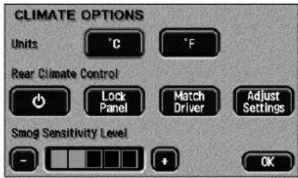
text_image
CLIMATE OPTIONS Units °C °F Rear Climate Control Lock Panel Match Driver Adjust Settings Smog Sensitivity Level - + OK
The Options button is displayed in place of the °C/°F button if the optional smog
sensor and/or rear climate control panel (4-zone system) are fitted.
Touching Options displays the Celsius (°C) and Fahrenheit (°F) selection buttons. The display also shows either the rear control panel buttons or the smog sensor setting or both.
SMOG SENSING
Where fitted, the smog sensor detects road traffic pollutants and automatically selects air recirculation when the level of pollution outside the vehicle reaches a certain level. The level of pollution at which the smog sensor will respond can be adjusted on the Options screen.
Once the level of pollutants decreases, air recirculation will switch off (subject to the normal operation of the automatic climate control system).
To adjust smog sensitivity: Touch the + button to increase sensitivity to low smog levels. Touch the - button to decrease sensitivity.
Caution: Don't set the smog sensor to a needlessly high level in cold and damp conditions: this could result in interior condensation.
REAR CLIMATE PANEL
Controlling the rear climate panel from the touch-screen
On the 'Climate Options' screen (see page 182) the 'Rear Climate Control' buttons provide control of the rear system:
- Touch the left-hand button to switch the rear control panel on or off.
- Touch Lock Panel to lock the rear climate control panel. This prevents rear passengers from altering the rear climate settings, until the next time the ignition is switched on.
- Touching Match Driver causes the rear zones to adopt the same settings as the driver's zone. Any adjustments made directly on the rear panel will override these settings.
- Touch Adjust Settings to alter the settings of the rear zones. A simulation of the rear control panel will be displayed on the touch-screen.
Touch-screen Climate Control
Simulated rear control panel

text_image
REAR CLIMATE CONTROL 23.0 23.0 Auto Mode OKThe simulation of the rear climate control panel allows all of the rear climate functions to be controlled via the touch-screen.
Operation of these touch-screen buttons is as described for the rear panel itself in the owner's handbook.
Note: It is not possible to make adjustments on the actual rear panel while the touch-screen simulation of the panel is displayed. The touch-screen display will revert to the main climate screen 30 seconds after the last touch.
Inertia Switch
INERTIA SWITCH OPERATION
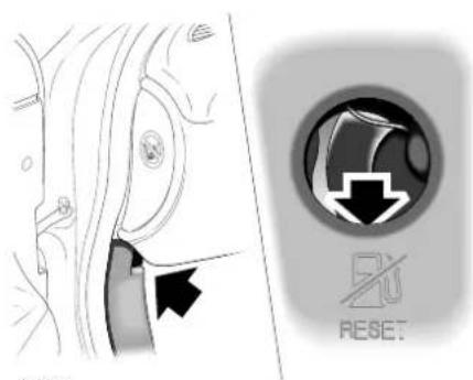
text_image
Diagram showing car door and seat with directional arrow and 'RESET' button, likely illustrating vehicle safety or reset mechanism.JAG0647
In the event of an accident, the inertia switch may trip (depending on the severity and type of impact), isolating operation of the fuel pump. Once the switch has tripped it must be reset before attempting to restart the engine.
The inertia switch is located behind the trim on the left-hand side of the vehicle, forward of the front door post, below the facia. A finger access hole in the trim allows the driver to reset the switch.
To Reset the Switch

WARNING:
To avoid the possibility of fire or personal injury, do not reset the inertia switch if you see or smell fuel.
If no fuel leak is apparent, reset the inertia switch as follows:
- Turn the ignition switch to position 0.
- Press down the red reset button on the top of the inertia switch.
- Turn the ignition switch to position II, pause for a few seconds, then return the key to position 0.
- Make a further check for fuel leaks.
Emergency Starting
ROLLING START
This vehicle is fitted with automatic transmission. In the event of a discharged battery preventing a normal engine start, the vehicle cannot be started by pushing or towing. Either use jump leads connected to a booster battery (e.g. on another vehicle) or fit a fully charged battery.
USING JUMP LEADS
Both the booster and discharged battery should be treated with great care when using jump leads. Always use high quality leads capable of carrying the starter current of the vehicle to be started.

WARNING:
To avoid serious injury use extreme caution when removing the booster cables as the engine will be running on the previously disabled vehicle. This means that you will be working close to components which are moving at high speed, carry high voltage, or may be hot.
Before commencing, the following precautions must be taken:
- When the battery of another vehicle is being used, ensure that the vehicles do not touch. Alternatively, remove the charged battery and place near to, not on, the vehicle with the discharged battery.
- Ensure that both vehicles have all electrical services OFF, the parking brakes applied and the transmission in the P (park) position.
- Where the jump leads are of a different colour, e.g. red and black, use red for positive (+). This aids identification and helps to avoid crossing positive (+) to negative (−). Take extra care to avoid crossing the polarity when using cables of the same colour.
Caution: If using a jump start vehicle, under no circumstances should the vehicles come into contact with each other. This could establish an earth connection, which may cause sparks and damage.
Caution: Do not run the engine of the jump start vehicle when boost starting a Jaguar vehicle. If the jump start vehicle's engine is running and the jump leads are disconnected, damage to the Jaguar vehicle's electrical system will result.
Note: The booster battery must be of the 12 volt type.
Emergency Starting
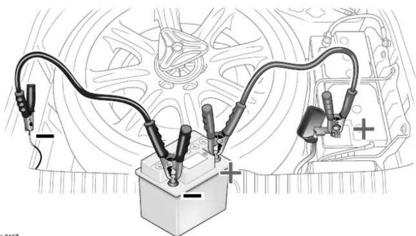
natural_image
Diagram of automotive electrical connections with battery, wires, and motor (no text or labels)JOL3167
The procedure must be followed exactly, being careful not to cause sparks:
- Gain access to the battery which is under the luggage compartment floor (see page 187) and unclip the battery positive (+) terminal cover.
- Attach one end of the red jump lead to the positive (+) terminal of the booster battery and the other end to the positive (+) terminal of the discharged battery. Make sure that a good connection is made.
Caution: Do not connect the negative jump lead directly to the negative (-) terminal of the discharged vehicle.
- Attach one end of the black jump lead to the negative (−) terminal of the booster battery and the other end to the earth stud on the left-hand side of the spare wheel well.
-
Start the engine of the vehicle with the discharged battery.
-
When started, allow the engine to idle for five minutes before disconnecting the cables.
- Disconnect the black jump lead from the earth point and the booster battery negative (−) terminal.
- Disconnect the red jump lead from the positive (+) terminals of both batteries.
- Refit the cover to the positive (+) terminal.
- Close the luggage compartment floor panel.
After starting the engine, it may be necessary to reset the Electric Parking Brake.
Also, see After battery reconnection on page 228.
Wheel Changing
LUGGAGE COMPARTMENT UNDERFLOOR ACCESS
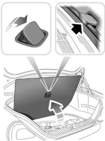
text_image
Diagram illustrating vehicle door panel installation with directional arrows and component placementE86403
The space under the luggage compartment floor houses the spare wheel, battery, jack and rear fuse box.
To raise the floor panel, press down the rear of the handle then, holding the handle at the front, swing the floor panel upwards. Hook the handle over the top edge of the luggage compartment opening.
Be prepared for a flat tyre. Know where equipment is stowed and read the wheel changing and jacking instructions carefully. Keep the jack screw threads clean and greased to ensure it is always ready for an emergency.
Park off the road, clear of all traffic and on as level, solid ground as possible. Switch on hazard warning lamps and, where legally required, display the warning triangle.
Caution: Ultra high performance tyres. This vehicle is equipped with Ultra High Performance (UHP) tyre and wheel combinations designed to provide maximum dry road performance with consideration for hydroplaning resistance. These low profile high speed rated tyres may be more susceptible to damage from road hazards. UHP tyres have performance enhancing soft rubber tread compounds, which when driven aggressively experience rapid tread wear and shorter life than less performance oriented tyres.
These tyres are not recommended for driving on snow or ice, and should be replaced with winter tyres when weather conditions dictate.
Tyres with all season and M + S icon have a level of winter performance and need not be replaced.


WARNING:
It can be dangerous to change a wheel when the vehicle is on a slope or soft, uneven ground.
Wheel Changing
TEMPORARY-USE SPARE WHEEL
Note: Maintenance information for the temporary-use spare wheel is the same as given for normal tyres.
Observe the following warnings before using the wheel:

WARNING:
Please note the temporary-use spare wheel warning label on the wheel. Adhere to instructions on the label. Failure to comply can be dangerous.

WARNING:
Temporary-use spare wheel maximum speed is 80 km/h (50 mph).

WARNING:
When a temporary spare wheel is fitted, drive with caution and replace with the specified wheel and tyre as soon as possible.

WARNING:
Do not fit more than one temporary-use spare wheel and tyre assembly at a time.

WARNING:
The temporary-use spare wheel must be inflated to the correct pressure of 4.1 bar (60 lb/in2).

WARNING:
If the vehicle is fitted with a Tyre Pressure Monitoring (TPM) System, please refer to page 235.

WARNING:
DSC must be ON when the temporary use spare wheel is in use.
LOCKING WHEEL NUTS
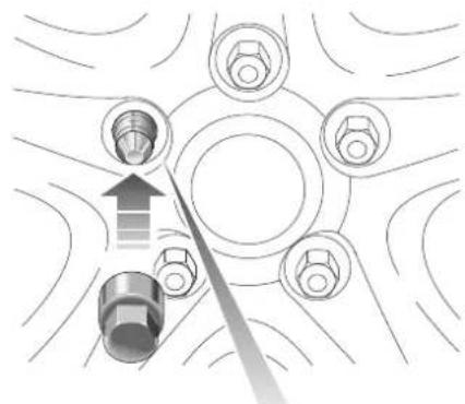
natural_image
Diagram of a mechanical assembly with bolt holes and a directional arrow indicating motion (no text or labels)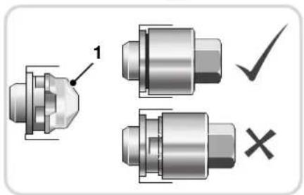
text_image
1 ✓ ×E86405
Where Jaguar locking wheel nuts are fitted (one on each wheel), they can only be removed using the correct key socket.
Wheel Changing
The locking wheel nut comprises two grooved parts, front and rear, which must be turned together to allow the nut to be fitted or removed.
To remove the nut, the front and rear grooves must be aligned. Locate the key socket in the grooves and push it fully over both parts of the nut. Fit the wheel nut wrench over the key socket and loosen the locking wheel nut (turn anti-clockwise).
Attempting to remove the nut without the correct key socket (such as attempted theft) or with the socket not located over the rear part of the nut, will cause the front part only (see item 1) to turn.
If this has happened, rotate the front part with the key socket until the grooves are re-aligned and then push the socket fully over the nut.
Should a new key socket be required, contact your Jaguar Dealer/Authorised Repairer. Proof of vehicle ownership will be required.
SPARE WHEEL AND JACK
REMOVAL

natural_image
Illustration of a hand holding a circular mechanical component with a numbered arrow indicating direction (no text or symbols present)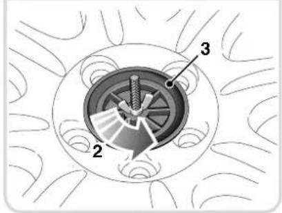
text_image
Technical diagram of a mechanical component with labeled parts 2, 3, and a central shaft or gear assembly.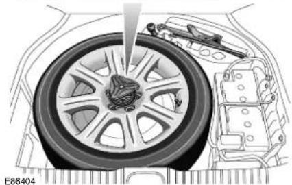
natural_image
Technical illustration of a car wheel assembly with internal components (no text or symbols)WARNING:
The spare wheel is heavy and if handled incorrectly may cause injury. Use extreme caution when lifting or manoeuvring the wheels.
Wheel Changing

WARNING:
Always secure the spare wheel, or the removed wheel, in the correct position using the retaining bolt. Failure to do so may cause the spare wheel to move in the event of a sudden manoeuvre or accident, leading to death or serious injury.

WARNING:
Ensure that the floor panel is placed where it cannot fall and cause injury when it is removed from the vehicle.

WARNING:
When removing or replacing the floor panel ensure that fingers and hands are kept clear. Failure to do so may result in crush injuries.
The spare wheel and jacking equipment are stored under the trunk floor panel.
To remove the spare wheel, fully unscrew and remove the locking ring (1). Unscrew and remove the wing nut (2) below the locking ring. This allows wheel retainer (3) to be lifted and removed. The wheel can now be lifted out.
WHEEL CHANGING PROCEDURE
Before raising the vehicle, or changing a wheel ensure that you read, and comply with the following warnings.

WARNING:
Always find a safe place to stop, off of the highway and away from traffic.

WARNING:
Ensure that the vehicle is on firm level ground.

WARNING:
Disconnect trailer/caravan from the vehicle.

WARNING:
Switch on the hazard warning lamps.

WARNING:
Ensure that all passengers and animals are out of the vehicle, and in a safe place away from the highway.

WARNING:
Place a warning triangle at a suitable distance behind the vehicle, facing towards oncoming traffic.

WARNING:
Ensure that the front wheels are in the straight ahead position, and engage the steering lock.
Wheel Changing

WARNING:
Apply the Electric Parking Brake (EPB), and engage Park in vehicles fitted with an automatic transmission.

WARNING:
Apply the EPB and engage 1st or reverse gear in vehicles fitted with a manual transmission.

WARNING:
Ensure that the jack is on firm, level ground.

WARNING:
Never place anything between the jack and the ground, or the jack and the vehicle.

WARNING:
Always chock the wheels using suitable wheel chocks. Place the chocks on both sides of the wheel, diagonally opposite the wheel to be changed.

WARNING:
If jacking the vehicle on a slight slope is unavoidable, place the chocks on the downhill side of the two opposite wheels.

WARNING:
Take care when lifting the spare wheel, and removing the punctured wheel. The wheels are heavy, and can cause injuries if not handled correctly.

WARNING:
Remove the spare wheel prior to jacking the vehicle. To avoid destabilising the vehicle when raised.

WARNING:
Take care when loosening the wheel nuts. The wheel brace may slip off if not properly attached, and the wheel nuts may give way suddenly. Either unexpected movement may cause an injury.
Ensure that all passengers are in a safe place, clear of the vehicle.
Apply the EPB and select gear position P (Park).
Ensure that the jack is placed on firm and level ground.
Note:
When one rear wheel is lifted off the ground, the selection of gear position P (Park) will not prevent the vehicle from moving and possibly slipping off the jack.
Wheel Changing

text_image
Technical diagram illustrating car assembly steps with labeled components and a hand holding a tool.
WARNING:
Ensure that the jack is correctly located onto the jacking point.
Observe the instructions printed on the jack.
Use the jack only for lifting the vehicle during wheel changing, and only use the jack which is stored in the vehicle.
Do not start or run the engine while the vehicle is only supported by a jack.

WARNING:
Never work beneath the vehicle, or place any part of your body beneath the vehicle with the jack as the only means of support. Always use suitable vehicle support stands which are approved for the weight of the vehicle.
Removing the wheel
Before raising the vehicle slacken, but do not remove, the wheel nuts.
There are four jacking points, two each side of the vehicle on the underside of the floor. These provide positive location for the jack.
To locate the jacking point, feel along the sill panel to the cut-away portion and then fit the jack to the body, as shown, not to the sill panel.
Caution:
Ensure before raising the vehicle that the jack is correctly positioned to avoid any damage to the vehicle sills or sill panels. Use only the correct jacking points, never use bumpers or any other part of the body to lift the vehicle.

WARNING:
Do not attempt to lift the vehicle unless the jack head is fully engaged in the jacking point.

WARNING:
Ensure that the EPB is applied.
Wheel Changing
Place the jack squarely beneath the appropriate jacking point. Ensure that the jack head is fully engaged. Carefully raise the vehicle by turning the jack handle and continue jacking until the tyre just clears the ground. Minimum tyre lift gives maximum vehicle stability.
Remove the wheel nuts and the wheel.
Centre badge
When changing the alloy road wheels, transfer the centre badge to the replacement wheel. Using the plastic tipped end of the wheel nut wrench handle, push the centre badge from its housing.
Push the centre badge into the replacement wheel.
Fitting the spare wheel
Fit the spare wheel and loosely secure with the wheel nuts.
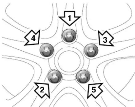
flowchart
graph TD
    A["1"] --> B["2"]
    C["3"] --> D["4"]
    E["5"] --> F["5"]
    G["6"] --> H["6"]
    I["7"] --> J["7"]
E86407
Using the wheel nut wrench, lightly tighten the wheel nuts alternately using the sequence shown in the illustration.
Lower the jack and tighten the wheel nuts alternately, DO NOT OVER TIGHTEN.
At the earliest opportunity have the wheel nuts tightened with a torque wrench to 125 Nm (92 lbf.ft).
This torque must not be exceeded.
Stowing the equipment
Stow the replaced road wheel in the trunk.
Check that the wing nut is unscrewed fully so that it is as close as possible to the handle of the wheel retainer. This is to ensure that the wheel retainer can be fitted correctly.
Locate the wheel retainer into its mating thread in the trunk floor, tighten it fully, then tighten the wing nut clockwise to secure the wheel.
Stow the jacking equipment.
Close the trunk floor panel.

WARNING:
When a temporary spare wheel is fitted, drive with caution and replace with the specified wheel and tyre as soon as possible.
Note:
If your vehicle is fitted with a TPM system, it may take a few minutes for the system to recognise the replaced wheel. Please see page 235 for further information on the TPM system.
Vehicle Recovery
The preferred vehicle recovery method is by using a flat-bed transporter or rear suspended tow.
Caution:
If the vehicle has defective transmission, to prevent further damage, it must be towed with the rear wheels clear of the ground.
Caution:
Ensure that the recovery team do not tow with sling-type equipment since damage to the bodywork may result.
Caution:
Do not tow the vehicle by suspending the front end.
TRANSPORTING
If the vehicle is being transported on a trailer or flat-bed transporter, the Electric Parking Brake (EPB) must be applied, the wheels chocked and the gear selector lever moved to position N or D but NEVER to P.
The vehicle must be securely tied down to the transporter or trailer.
Transporter tie-down procedure

WARNING:
Avoid body contact with a hot exhaust pipe when securing the vehicle to the transporter.
IMPORTANT: Use straps over the wheels/tyres only, to secure the vehicle to the transporter.
Caution:
Do not use the tie-down brackets on the vehicle rear underbody; these are for Jaguar factory use only. Do not lash the body to the transporter. In time, with the engine switched off, the vehicle body will drop due to settling of the air suspension system and cause the tie down chains/straps to become slack if connected to the tie-down brackets or to any part of the body.
The towing eye is not designed for securing the vehicle during transportation.
Vehicle failure
The removable towing eye is primarily for emergency use when towing for SHORT DISTANCES, e.g. removing the vehicle if it is causing an obstruction or for winching the vehicle onto a recovery transporter. To prevent damage to the automatic transmission whilst the vehicle is being towed with the rear wheels on the ground, towing distance must be restricted to 0.8 kilometres (0.5 miles). Towing speed must not exceed 48 km/h (30 mph).
Always obey towing regulations. In certain countries the registration number of the towing vehicle and an ON TOW sign or warning triangle must be displayed in a prominent position at the rear of the vehicle being towed.
When being towed, the gear selector lever must be in neutral (position N) with the ignition key turned to position II to release the steering lock and render the indicators, horn and brake lamps operational.
Vehicle Recovery

WARNING:
When the engine is not running the steering and brakes will no longer be power-assisted. Therefore be prepared for relatively heavy steering and the need for greatly increased brake pedal pressure.
TOWING EYE

WARNING:
The towing eyes at the front and rear of the vehicle are designed for on-road recovery only. If they are used for any other purpose it may result in vehicle damage and serious injury.

WARNING:
Never use the towing eyes to tow a trailer, caravan etc. Doing so may result in vehicle damage and serious injury.
A screw-in towing eye is provided in the luggage compartment with the jack and can be fitted to the front or rear of the vehicle. The towing eye has a left-hand thread and must be turned in an anti-clockwise direction when fitting.
Caution:
The towing eye is not suitable for solid bar towing.
Caution:
Care must be taken to avoid damaging the bumpers and front apron.
Front tow point
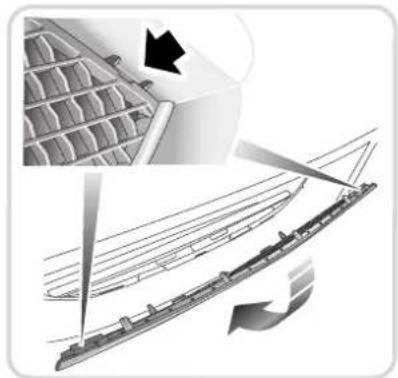
natural_image
Diagram showing structural components and airflow direction (no text or symbols)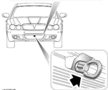
natural_image
Diagram showing a car front view and its internal mechanical component with a magnified inset (no text or symbols)JAG0648
The front tow point is located behind a plastic cover on the left-hand side of the vehicle, as viewed from the front.
To remove the cover, unclip the top edge, pivot down and unclip the bottom edge.
Screw the towing eye into the vehicle, right up to the shoulder, turning anti-clockwise (it has a left-hand thread).
To refit the cover (towing eye removed) first clip the lower edge to the bumper aperture, pivot up and press the top edge into position.
Vehicle Recovery
Rear tow point

WARNING:
Avoid body contact with a hot exhaust pipe when fitting the eye to the rear towing point.

text_image
Diagram showing car head and bottom view with a close-up of the lock mechanism, labeled 'AG0649'JAG0649
The rear tow point is alongside the left-hand exhaust pipe.
Screw the towing eye into the vehicle, right up to the shoulder, turning anti-clockwise (it has a left-hand thread).
Bulb Renewal
TOP ACCESS COVER
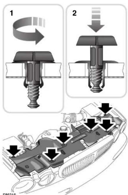
text_image
1 2 F86316To gain access to the headlamp units, the top cover must be removed.
Unscrew and remove the six fasteners 1. Remove the top cover.
After changing the defective bulb, refit the cover, push the fasteners 2 into place and then screw the fasteners fully in to retain the top cover.
When renewing bulbs, use only the specified type and always switch off the ignition and lamps.
HEADLAMPS
Either of two headlamp systems are fitted:
- Halogen headlamp bulbs in both the inner, high beam positions and the outer low beam positions.
- Halogen bulbs in the inner, high beam positions and High Intensity Discharge (HID) Xenon lamps in the outer positions. The HID system provides both low and high beam lamps.
Where HID lighting is fitted, refer to your Jaguar Dealer/Authorised Repairer if the headlamp fails to operate.

WARNING:
Replacement or maintenance of Xenon lamps should only be carried out by suitably qualified personnel.

WARNING:
High voltage is required to ignite the gas and metal vapour which are used to power Xenon lamps. Contact with this voltage can cause serious injuries.

WARNING:
Bi-Xenon lamp units operate at a very high temperature. Ensure that the lamp units have cooled before attempting to touch them.

WARNING:
Xenon lamp units contain Mercury which is highly toxic, and can be extremely harmful.
Bulb Renewal
Low beam (outer) headlamps
Open the bonnet and remove the top access cover, see page 197.
Pull the retaining clip 1 upwards. Move the top of headlamp assembly outer bulb cover rearwards to gain access to the bulbs.
Caution: Halogen bulbs will be damaged if touched by hand or contaminated with oil or grease. It is important to use clean gloves or clean cloth when handling a bulb which is to be used again. A contaminated bulb may be cleaned with methylated spirit before refitting.
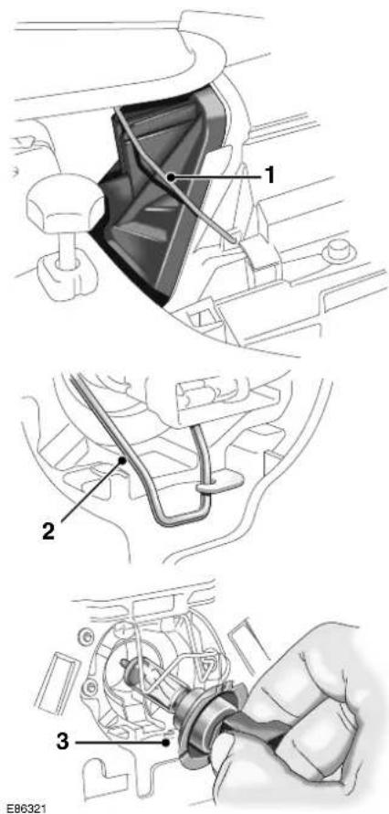
text_image
1 2 3 E86321Pull off the bulb connector. Release the bulb spring clip 2 from below the bulb and lift it clear of the bulb. Pull out the bulb from the headlamp assembly.
Locate the new bulb (type H7) into the headlamp with the bulb tab uppermost 3. The bulb will only fit correctly in one position.
Engage the spring clip 2 to secure the bulb. Fit the bulb connector.
Bulb Renewal
Refit the bulb cover to the headlamp assembly and secure with the retaining clip.
Refit the top cover and close the bonnet.
Note: It is advisable to have the headlamp aim checked by a Jaguar
Dealer/Authorised Repairer after bulb renewal.
High beam (inner) headlamp
Open the bonnet and remove the top cover, see page 197.
Caution: Halogen bulbs will be damaged if touched by hand or contaminated with oil or grease. It is important to use clean gloves or clean cloth when handling a bulb which is to be used again. A contaminated bulb may be cleaned with methylated spirit before refitting.
On the headlamp assembly, turn the rear inner cover (1) anti-clockwise as shown and remove.
Pull off the bulb connector. Release the bulb spring clip (2) from below the bulb and lift it clear of the bulb. Pull out the bulb from the headlamp assembly.
Locate the new bulb (type H7) into the headlamp with the bulb tab uppermost (3). The bulb will only fit correctly in one position.
Engage the spring clip (2) to secure the bulb. Fit the bulb connector.
Fit the rear cover and turn it clockwise to secure.
Refit the top cover and close the bonnet.
FRONT DIRECTION
INDICATORS
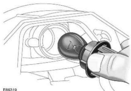
natural_image
Illustration of a hand holding a bulb-shaped connector into a vehicle head panel (no text or symbols visible)Open the bonnet and remove the top access cover, see page 197.
The front direction indicator bulb is located above the outer headlamp bulb (halogen or HID type) and is accessed via the outer bulb cover.
Turn the bulb holder a quarter turn anti-clockwise and pull out.
Remove the bulb and fit a new one of the correct type, PY21W.
Fit the bulb holder to the lamp unit, it will only fit in one position. Turn clockwise to secure. Refit the headlamp assembly outer bulb cover and secure with the retaining clip.
Refit the top cover and close the bonnet.
Bulb Renewal
FRONT PARKING (SIDE) LAMP
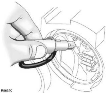
natural_image
Hand holding a coiled spring component inside a mechanical housing (no text or symbols visible)SIDE REPEATER INDICATOR
Open the bonnet and remove the top access cover, see page 197.
On the high beam inner headlamp assembly, turn the rear inner cover anti-clockwise (see page 199) and remove.
Turn the bulb holder anti-clockwise to remove it from the headlamp assembly.
Remove the bulb from the holder and fit a new one of the correct type, W5W.
Reposition the bulb holder in the headlamp unit and turn it clockwise.
Fit the rear cover and turn it clockwise to secure.
Refit the top cover and close the bonnet.
To remove the lamp unit from the external mirror, firstly pull the glass from the mirror unit to reveal the side repeater lamp holder. Gently release the rubber grommet and pull the lamp holder from its housing.
Remove the bulb and fit a new one of the correct type, WY5W.
Refit the bulb holder, ensuring the rubber grommet is firmly in place. Gently push the mirror glass back into place until a click is heard.
Bulb Renewal
NUMBER PLATE LAMP

natural_image
Hand holding a small object with labeled terminals (A, U, I) and a knob, no readable text or symbols present.Press the two lens clips inwards and remove the lens from the vehicle.
Remove the bulb and fit a new one of the correct type, W5W.
Refit the lens by pressing it firmly into the recess until it clicks into place.
FRONT FOG LAMP
It is recommended that the front fog lamp bulb, type H3, is renewed by a Jaguar Dealer/Authorised Repairer.
REAR LAMP ASSEMBLY
On the rear lamp assemblies, only the direction indicator, reverse and fog bulbs are replaceable. The stop/tail lamps consist of arrays of LED lamps which can only be renewed by a Jaguar Dealer/Authorised Repairer if they fail to operate.
Ensure that the lamps and ignition switch are OFF before removing any bulbs.
Open the luggage compartment and secure the floor panel in the open position see page 187.
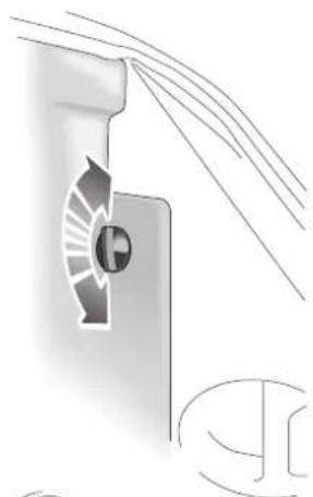
natural_image
Technical illustration of a mechanical component with curved lines and a circular symbol (no text or labels)
text_image
1 2 3 E86323Rotate the side carpet trim fastener a quarter turn and remove. Pull back the side carpet trim to access the rear of the lamp assembly.
The bulb positions are:
- Reverse lamp, type P21W.
- Direction indicator, type PY21W.
- Fog lamp, type P21W.
Bulb Renewal
Rotate the bulb/connector and withdraw it from the assembly. Remove the faulty bulb and fit a new one of the correct type, as illustrated on the bulb holder. It is essential to fit the correct type.
Reposition the bulb/connector and turn it to secure.
Carefully refit the side carpet trim. Fit fastener and rotate a quarter turn.
Close the luggage compartment floor panel.
Fuses
CHANGING FUSE
Spare fuses and a tool for removing and replacing fuses are located on a removable panel clipped to the rear of the luggage compartment. See diagram.
Caution: Always turn off the starter switch, and the affected electrical circuit, before replacing a fuse.
Caution: Fit Jaguar approved replacement fuses of the same rating and type, or fuses of matching specification. Using an incorrect fuse may result in damage to the vehicle's electrical system, and can result in a fire.
Caution: If the replacement fuse blows after installation, the system should be checked by your Jaguar Dealer/Authorised Repairer.
Caution: No attempt should be made to repair a fuse that has blown.
Make sure the new fuse is the correct rating (amperage).
Fuses are colour coded according to the amperage and the rating is also marked on each fuse.
Caution: When a fuse box lid is removed, take care to protect the box from moisture, and refit the lid at the earliest opportunity.
Caution: Relays should only be removed and replaced by suitably qualified persons.

text_image
A JOL3094ATO-fuse replacement
Push the tool onto the suspect ATO-fuse and withdraw the fuse. If the wire in the fuse is broken, the fuse has blown.
Fit a new fuse using the tool.
Fuses
FUSE BOX LOCATIONS
There are three separate fuse boxes fitted to the vehicle, each one containing fuses protecting a different group of circuits:
- Engine compartment fuse box, either for the petrol or diesel engine vehicles.
- Cabin fuse box.
• Luggage compartment fuse box.
Engine compartment fuse box

natural_image
Illustration of an open battery case with a white arrow pointing upward, surrounded by wiring and components (no text or symbols)The fuse box is located in the engine compartment on the right-hand side, adjacent to the windscreen wash reservoir.
Remove the fuse box lid by pressing the spring catch and lifting.
When refitting, press the fuse box lid in the area of the retaining lugs until the lid engages.
Fuses
Cabin fuse box
Luggage compartment fuse box
E86412
The cabin fuse box is located behind the right-hand side trim panel in the footwell. To access the fuse box, pull out the bottom of the trim panel (arrowed), slide the panel down slightly and remove.
E86414
This fuse box is located in the luggage compartment, situated behind the battery. Open the luggage compartment floor panel to gain access to the fuse box. Remove the fuse box lid by pulling the retaining clips and pulling the lid upwards. Reposition the lid and press down until the retaining clips engage. Replace the floor panel.
Fuses
FUSE POSITIONS
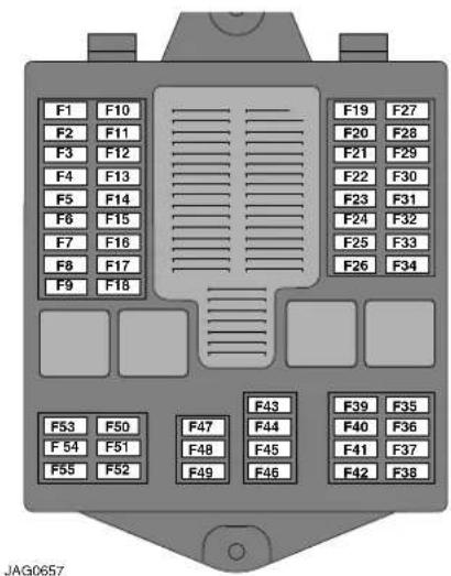
text_image
F1 F10 F2 F11 F3 F12 F4 F13 F5 F14 F6 F15 F7 F16 F8 F17 F9 F18 F19 F27 F20 F28 F21 F29 F22 F30 F23 F31 F24 F32 F25 F33 F26 F34 F53 F50 F54 F51 F55 F52 F47 F44 F48 F45 F49 F46 F43 F39 F35 F40 F36 F41 F37 F42 F38 JAG0657Luggage compartment fuse box.
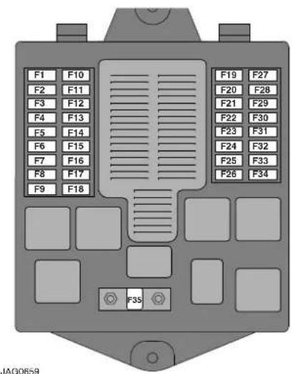
text_image
F1 F10 F2 F11 F3 F12 F4 F13 F5 F14 F6 F15 F7 F16 F8 F17 F9 F18 F19 F27 F20 F28 F21 F29 F22 F30 F23 F31 F24 F32 F25 F33 F26 F34 F35Engine compartment fuse box
Fuse ratings and colour
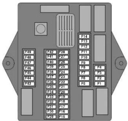
text_image
F49 F42 F28 F48 F41 F27 F47 F40 F26 F46 F39 F25 F45 F38 F24 F44 F37 F23 F43 F36 F22 F35 F21 F34 F20 F33 F19 F32 F18 F31 F17 F30 F16 F29 F15 F14 F13 F12 F11 F10 F9 F8 F4 F7 F3 F6 F2 F5 F1JAG0658
Cabin fuse box.
| Rating (amps) | Colour |
| 5A TAN | |
| 10A RED | |
| 15A BLUE | |
| 20A YELLOW | |
| 25A NATURAL | |
| 30A GREEN | |
| 40A ORANGE |
Fuses
Engine compartment fuse box - petrol engine vehicles
| Fuse No. | Rating (amps) | Circuit |
| F1 5A Front ignition, UHEGO, fuel pump, rear ignition relay coils | ||
| F2 10A Throttle (petrol engine only) | ||
| F3 5A DSC ECU | ||
| F4 30A Powerwash pump | ||
| F5 Not used | ||
| F6 40A Air suspension compressor | ||
| F7 40A Right-hand front screen heater or wiper park zone heater | ||
| F8 20A Right-hand low beam | ||
| F9 20A Left-hand low beam | ||
| F10 15A Horns | ||
| F11 Not used | ||
| F12 10A Engine control module, VVT solenoids | ||
| F13 10A Fuel injectors | ||
| F14 10A Purge valve, EGR valve, DMTL, V6 intake manifold tuning valves (IMTV), MAFS, air filter solenoid, radiator fan controller | ||
| F15 Not used | ||
| F16 20A Right-hand high beam, left-hand high beam | ||
| F17 10A Engine control module, transmission control module | ||
| F18 15A Front fog lamps, instrument panel front fog status | ||
| F19 25A Starter solenoid | ||
| F20 40A ABS module (pump) | ||
| F21 Not used | ||
| F22 20A ABS module | ||
| F23 Not used | ||
| F24 20A Intercooler water pump (supercharged engines) | ||
| F25 Not used | ||
| F26 40A Wiper system, front electronics module (FEM) | ||
| F27 5A Secondary air injection | ||
| F28-F29 Not used | ||
| F30 15A Ignition coils | ||
| F31 Not used | ||
| F32 40A Left-hand front screen heater | ||
| F33 30A A bank heated oxygen sensors | ||
| F34 30A B bank heated oxygen sensors | ||
| F35 80A Radiator cooling fan | ||
Fuses
Engine compartment fuse box - diesel engine vehicles
| Fuse No. | Rating (amps) | Circuit |
| F1 5A Fuel pump, rear ignition relay coils | ||
| F2 Not used | ||
| F3 5A DSC ECU | ||
| F4 30A Powerwash pump | ||
| F5 Not used | ||
| F6 40A Air suspension compressor | ||
| F7 40A Right-hand front screen heater or wiper park zone heater | ||
| F8 20A Diesel EMS, VBR's, PCV and VCV | ||
| F9 15A Diesel EMS, cooling fan, MAFS, IPDA, Glowplug module, AEM's | ||
| F10 20A Right -hand low beam | ||
| F11 Not used | ||
| F12 Not used | ||
| F13 20A Left-hand low beam | ||
| F14 Not used | ||
| F15 Not used | ||
| F16 20A Right-hand high beam, left-hand high beam | ||
| F17 10A Engine control module, transmission control module | ||
| F18 15A Front fog lamps, instrument panel front fog status | ||
| F19 25A Starter solenoid | ||
| F20 40A ABS module (pump) | ||
| F21 FFH Battery + | ||
| F22 20A ABS module | ||
| F23 Not used | ||
| F24 Not used | ||
| F25 15A Horn | ||
| F26 40A Wiper system, front electronics module (FEM) | ||
| F27 5A EMS Battery + | ||
| F28, F29 Not used | ||
| F30 Not used | ||
| F31 Not used | ||
| F32 40A Left-hand front screen heater | ||
| F33 Not used | ||
| F34 10A Auxiliary water pump | ||
| F35 80A Radiator cooling fan | ||
Fuses
Cabin fuse box
| Fuse No. | Rating (amps) | Circuit |
| F1 10A Climate control unit, fan, screen heaters and wiper relay coils, smog sensor | ||
| F2 5A Cruise control switch, adaptive cruise control | ||
| F3 5A Rear outer seat, electrochromic mirror, driver seat heater, electric parkbrake, left-hand and right-hand HID lamps levelling, left-hand and right-hand seat belt switches, passenger seat heater switch, rear seat heater switchpack | ||
| F4 5A Instrument panel | ||
| F5, F6 Not used | ||
| F7 5A Cigar lighter, sunroof module, sunblind motor, electric parkbrake switch illumination, accessory relays (luggage compartment fuse box) | ||
| F8 5A Instrument panel | ||
| F9 10A Left-hand direction indicator and door mirror repeater | ||
| F10 10A Glove compartment door motor and lamps | ||
| F11 5A Radio muting (engine start), ignition feed | ||
| F12 10A Front electronic module (FEM), passenger mirror | ||
| F13 20A Rear electronic module (REM), door locks | ||
| F14 10A Climate control, footwell lamps, FEM, autolamp module | ||
| F15 5A ECM, FEM, instrument panel airbag fault lamp, instrument panel ignition (run/start) | ||
| F16 5A Diagnostic connector | ||
| F17 5A ABS module | ||
| F18 Not used | ||
| F19 5A Ignition relay, ECM, REM, fuel pump relay, start relay | ||
| F20 5A Telephone transceiver, TV module, VICS (Japan), voice module, rear telematics | ||
| F21 20A Passenger's ventilated seat | ||
| F22- F23 Not used | ||
| F24 5A PATS transponder | ||
| F25 10A Right-hand direction indicator and door mirror repeater, right-hand front lamp, left-hand and right-hand sunvisor lamps, left-hand and right-hand sidemarkers | ||
| F26 15A Screenwash pump | ||
| F27 10A ACC module | ||
| F28 10A Climate control modules (front and rear), driver's door module (DDM) | ||
Fuses
| Fuse No. | Rating (amps) | Circuit |
| F29 10A Airbag module, occupancy sensing module, passenger weight sensor, PAD lamp | ||
| F30 20A Driver's ventilated seat | ||
| F31 15A Sunroof, phone transceiver | ||
| F32 5A Front/rear parking aid, trailer tow module, battery-backed sounder, voice module, telephone receiver | ||
| F33 5A Transmission control, J-gate, alternator | ||
| F34 5A Navigation system, remote power amp | ||
| F35 10A Passenger seat movement | ||
| F36 40A Passenger seat movement, DSM | ||
| F37 25A Driver window | ||
| F38 15A Radio head unit | ||
| F39 5A Transit relay (removed before customer delivery) | ||
| F40 10A Security LED, yaw rate sensor | ||
| F41 20A Ignition switch | ||
| F42 10A FEM, REM, DDM, EPB logic | ||
| F43 5A Diagnostic connector | ||
| F44 5A Brake switch | ||
| F45 10A Passenger seat movement | ||
| F46 25A Passenger window | ||
| F47 5A Instrument pack | ||
| F48 20A Instrument pack (steering column tilt and reach) | ||
| F49 40A Driver seat movement | ||
Fuses
Luggage compartment fuse box
| Fuse No. | Rating (amps) | Circuit |
| F1-F4 Not used | ||
| F5 40A Passenger seat switchpack | ||
| F6 10A Accessory connector | ||
| F7 40A Front blower motor | ||
| F8 10A Heater circuit water pump | ||
| F9 25A Rear seat motors | ||
| F10 Not used | ||
| F11 5A Rear footwell lamps, grab handle lamps, overhead console map lamps | ||
| F12 10A Air suspension | ||
| F13 20A Rear seat entertainment | ||
| F14 Not used | ||
| F15 5A Right-hand stop and tail lamps | ||
| F16 10A Luggage compartment lamps, driver seat switch pack, rear switch seat pack, blower motor relay coil | ||
| F17 10A Left-hand rear fog, direction indicator and reversing lamps | ||
| F18 10A Number plate lamps, side marker lamps | ||
| F19 30A Heated rear window | ||
| F20 10A Heated door mirrors | ||
| F21 25A Rear seat motors | ||
| F22 10A Accessory connector | ||
| F23 Not used | ||
| F24 25A Fuel pump driver module | ||
| F25 15A Front accessory socket | ||
| F26 15A Rear accessory socket | ||
| F27 10A Rear CD | ||
| F28 25A Left-hand rear window | ||
| F29 5A VICS (Vehicle Information and Communication System) - Japan only | ||
| F30 10A Alternator, battery-backed sounder, transit relay | ||
| F31 40A Passenger front seat | ||
| F32 30A Electric parkbrake actuator | ||
| F33 20A Rear electronic module (fuel pump) | ||
| F34 30A Power amplifier | ||
| F35-F36 Not used | ||
| F37 10A TPM System Battery + | ||
Fuses
| Fuse No. | Rating (amps) | Circuit |
| F38 Not used | ||
| F39 15A Gateway module | ||
| F40 25A Right-hand rear window | ||
| F41, F42 Not used | ||
| F43 15A Rear cigar lighter | ||
| F44 15A Front cigar lighter | ||
| F45 Not used | ||
| F46 10A Right-hand rear reverse, direction indicator and fog lamps | ||
| F47 20A FEM, front seat heater | ||
| F48 5A High mounted stop lamps | ||
| F49 5A Left-hand stop and tail lamps | ||
| F50 Not used | ||
| F51 10A Navigation system | ||
| F52 20A Air suspension | ||
| F53 20A Rear fan motor | ||
| F54 15A Heated steering wheel | ||
| F55 5A TPM System | ||
Fire Extinguisher
DEALER FITTED FIRE EXTINGUISHER
Many countries make it compulsory to carry a fire extinguisher. Your Jaguar Dealer/Authorised Repairer can supply and fit one.
FACTORY FITTED FIRE EXTINGUISHER
(Where fitted)
Some countries have a factory fitted fire extinguisher which contains powder pressurised with nitrogen.
This extinguisher can be used on liquid fires, electrical equipment fires and, if no explosion risk, gaseous fires.

WARNING:
Do not test the fire extinguisher prior to use. Partial discharge will render the extinguisher inoperative.

WARNING:
Do not use the fire extinguisher closer than 2.4m (8 feet) to the base of a liquid fire as the force may splatter the burning liquid to the surrounding area.
Operating the Fire Extinguisher
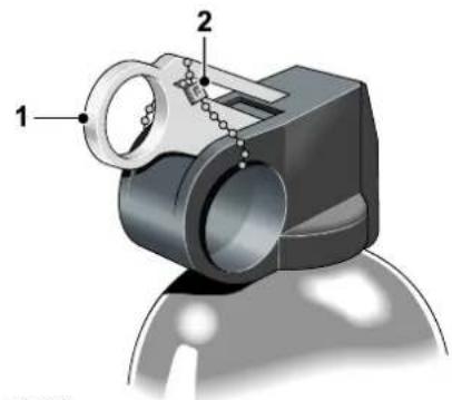
natural_image
3D mechanical component diagram showing a cylindrical housing with two labeled parts (1 and 2), no visible text or symbols.JAG0650
- Unclip and remove the extinguisher from the bracket.
- Put your finger through the yellow safety wedge ring (1) and pull hard to remove the wedge. The operating lever will be exposed.
- Hold the extinguisher upright and aim at the base of the fire.
- Press the lever down firmly.
- Release the lever to stop the flow of powder.
Maintenance
Every six months:
- Remove the extinguisher from its bracket and check that the nozzle is clear.
- Check that the safety wedge strap (2) is secure.
Check the pressure gauge on the base of the extinguisher. If the gauge is in the red area report it to your Jaguar Dealer/Authorised Repairer immediately as the extinguisher may not work in an emergency.
General Maintenance
REGULAR CHECKS
In the interests of safety and reliability, it is advisable to carry out the following checks at the recommended intervals, and always before starting on a long journey.
DAILY
Check that there is sufficient fuel for the journey intended, particularly at night and before joining motorways.
WEEKLY
Tyres
Check the tyres, including the spare, for condition and pressure. Tyre pressures are explained on page 250, and shown on a label inside the fuel filler flap.
Lamps
Check that all exterior lamps and direction indicators function correctly and that the lenses are clean.
Engine oil
With the vehicle standing on level ground, check the oil level and top up if necessary with oil of the correct grade.
Engine coolant
With the engine cold, check the level of the coolant in the coolant reservoir header tank. Any loss of fluid must be checked by a Jaguar Dealer/Authorised Repairer.
Brake fluid
Check the level of the fluid in the brake fluid reservoir. Top-up if necessary with new, unused Jaguar approved brake fluid.
The reservoir is initially nearly full, but the level will drop as the brake pads wear. If the level appears unusually low, location of the fluid leakage must be checked by a Jaguar Dealer/Authorised Repairer.
Power steering fluid
With the engine cold, check the level of the fluid in the power steering fluid reservoir. Top up if necessary with fluid of the correct specification. Any loss of fluid should be checked by a Jaguar Dealer/Authorised Repairer.
MONTHLY
Windscreen washer fluid
Top up with recommended windscreen washer fluid and clean soft water. Check the operation of the washers. Use Jaguar Windscreen Washer Fluid to keep the glass clean and also to prevent the fluid from freezing during cold weather.
Wiper blades
Check the quality of the wipe. If smearing or juddering is evident, clean the windscreen and wiper blades.
Bonnet Release
BONNET OPENING AND CLOSING

text_image
E86388WARNING:
Before closing the bonnet ensure that nobody is obstructing the closing area and that hands and clothes are clear. Remove tools, cleaning cloths, etc., from the engine compartment.
Close the bonnet to within a distance of 300 to 350 mm (12 to 14 inches) of the fully closed position, then let go to allow the bonnet to shut. Check by pulling the bonnet that both the right-hand and left-hand latches are engaged.
WARNING:
Do not drive with the bonnet retained by the safety catch alone.
WARNING:
Take care to keep away from rotating components if the engine is running when you open the bonnet.
Release the bonnet lock by pulling the lever below the facia on the left-hand side of the vehicle.
Lift the bonnet slightly and push the safety catch, located under the centre of the front edge of the bonnet. The gas filled struts will assist raising the bonnet, and retain it in the fully open position.
Regular Checks
DIPSTICK AND RESERVOIR
LOCATIONS
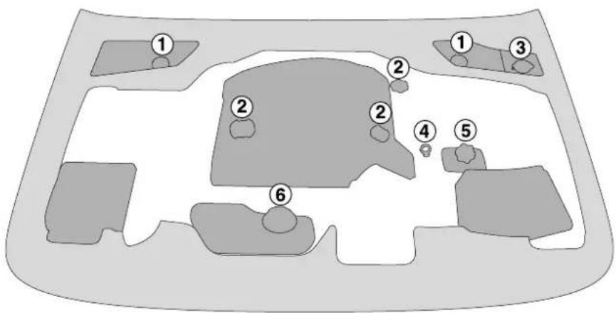
text_image
Diagram of a vehicle or road intersection with numbered locations marked 1 through 6.E86389
- Brake reservoir.
- Engine oil filler.
- Windscreen wash reservoir.
- Engine oil dipstick.
- Power steering reservoir.
- Coolant reservoir.
Checking and Top-up
ENGINE OIL LEVEL
Petrol engines
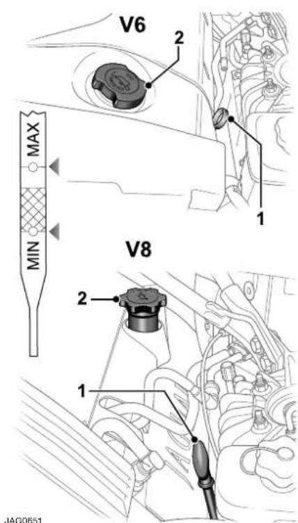
text_image
V6 2 1 MAX MIN V8 2 1 JAG0651Check the oil level regularly with the vehicle on flat, level ground, see pages 216 for dipstick and oil filler locations.
It is preferable to check the oil level after the vehicle has been standing, that is, with the engine completely cold.
If the engine has been started do not check the oil level until the engine has reached normal operating temperature. Stop the engine and wait for a minimum of five minutes to allow the oil to drain back into the sump.
Remove the dipstick (1) and wipe clean with a non-fluffy cloth. Replace fully, then withdraw the dipstick. If the oil level is above the lower of the two dots on the dipstick then no additional oil is required.
If the oil level reaches the lower of the two dots, remove the oil filler cap (2) and add 1.0 litre (1.76 Imperial pints) of oil, to the specification shown on page 218.
Refit the filler cap and hand tighten securely.
Caution: Your vehicle warranty may be invalidated if damage is caused by using oil that does not meet the required specification.
Caution: Failure to use an oil that meets the required specification could cause excessive engine wear, a build up of sludge and deposits, and increase pollution. It could also lead to engine failure.
Caution: Overfilling with oil could result in severe engine damage. Oil should be added in small quantities and the level re-checked to ensure that the engine is not overfilled.
Checking and Top-up
Diesel engines

text_image
MAX MIN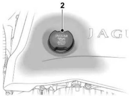
text_image
2 JAGUAR JAGUJAG0652
Remove the dipstick (1) and wipe clean with a non-fluffy cloth. Replace fully, then withdraw the dipstick. If the oil level is above the mark MIN on the dipstick then no additional oil is required.
If the oil is at or below the MIN mark, remove the oil filler cap (2) and add 1 litre of oil to the recommended engine oil on page 218.
Refit the dipstick and filler cap and securely tighten the filler cap by hand.
Recommended engine oil
Jaguar recommends Castrol
Oil specification - Petrol engine
An oil of 5W-30 viscosity to Jaguar specification WSS M2C913 - B must be used in all vehicles with a petrol engine.
For top up purposes only, where the WSS M2C913 - B specification cannot be found, ACEA A3/B3 or ACEA A1/B1 specification oils may be used.
Oil specification - Diesel engine
An oil of 5W-30 viscosity meeting Jaguar specification WSS M2C913 – B is preferred. Where this is not possible, oil meeting ACEA B1 or ACEA B3 may be used.
SAE viscosity rating
For climates ranging from -30^ ( -22^ ) and +50^ ( +122^ ), the following oil viscosities may be used:
0W-30
5W-30 (preferred)
0W-40
5W-40
Note: It is recommended that the oil level is topped up using oil of the same viscosity. If you are unsure which oil viscosity is used in your car, your Jaguar Dealer/Authorised Repairer will be able to advise.
If you are operating this vehicle in climates outside the above temperature range, contact your Jaguar Dealer/Authorised Repairer for advice.
Checking and Top-up
Engine Oil Consumption
A certain amount of oil consumption is normal. The rate of consumption will depend on the following:
• The quality and viscosity of the oil.
- The amount of oxidation and dilution of the oil.
- Climatic conditions.
- The speed at which the engine is being operated.
- Road conditions.
Drivers should expect above normal consumption when the engine is new, and after running-in if high speeds are sustained.
Used Engine Oil

WARNING:
Prolonged and repeated contact may cause serious skin disorders, including dermatitis and cancer.
Always use a hand cream to protect the skin from oil contamination. Avoid contact with the skin as far as possible and wash thoroughly after any contact. Keep oils out of reach of children.
PROTECT THE ENVIRONMENT: It is illegal to pollute drains, watercourses and soil. Use authorised waste collection facilities, including civic amenity sites and garages providing facilities for the disposal of used oil, oil filters and batteries. If in doubt, contact your Local Authority for advice on disposal.
| Engine oil capacity | |
| Litres | |
| V6 engine, including oil filter 6.5 | |
| V8 engine, naturally aspirated, including oil filter 6.0 | |
| V8 engine, supercharged, including oil filter 6.8 | |
| Diesel engine, including oil filter 6.6 | |
| TransmissionThe rear axle (final drive unit) and automatic transmission unit will not normally require to be checked or topped up. | |
Checking and Top-up
POWER STEERING FLUID
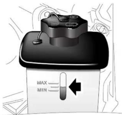
text_image
MAX MINE86399
Caution: It is imperative that the power steering system does not become contaminated in any way. Always dispense fluid from a fresh sealed container and clean the area around the reservoir neck both before and after topping up. Never return drained fluid to the system.
Refer to page 216 for the power steering fluid reservoir location.
Check the fluid level when the engine is COLD and the vehicle is on a flat, level surface.
The fluid is visible through the translucent casing of the reservoir. Check that the fluid level is between the MIN and MAX marks on the side of the reservoir.
If necessary, top up with power steering fluid as specified by your Jaguar Dealer/Authorised Repairer. Wipe clean and remove the filler cap from the reservoir; take great care to prevent any foreign matter from entering.
DO NOT OVERFILL.
Refit the filler cap.
Should the level be very low, report the loss of fluid to the nearest Jaguar Dealer/Authorised Repairer.

WARNING:
Do not allow power steering fluid to make contact with skin or eyes. If this happens, rinse the affected area immediately with plenty of water.

WARNING:
Power steering fluid is toxic and flammable. Be sure to observe all warnings indicated on the power steering fluid container.

WARNING:
Power steering fluid is highly toxic. Keep containers sealed and out of reach of children. If accidental consumption of fluid is suspected, seek medical attention immediately.

WARNING:
If the fluid comes into contact with the skin or eyes, rinse immediately with plenty of water.
Caution: The engine must not be started if the fluid level has dropped below the MIN mark. Severe damage to the steering pump could result.
Caution: Seek qualified assistance immediately if there is a noticeable drop in the fluid level. Severe damage to the steering pump could result.
Checking and Top-up
Caution: Power steering fluid will damage painted surfaces. Soak up any spillage with an absorbent cloth immediately and wash the area with a mixture of car shampoo and water.
Caution: Do not fill the reservoir above the MAX mark.
BRAKE FLUID RESERVOIR

text_image
MAX MIN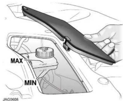
text_image
MAX MIN JAG0608WARNING:
Brake fluid is highly toxic - keep containers sealed and out of the reach of children. If accidental consumption of fluid is suspected, seek medical attention immediately.
WARNING:
If the fluid comes into contact with the skin or eyes, rinse immediately with plenty of water.
WARNING:
Take care not to spill the fluid onto a hot engine - a fire may result.
WARNING:
Do not drive the vehicle with the fluid level below the MIN mark.
Refer to pages 216 for the brake fluid reservoir location. The reservoir is concealed by a lift-out cover.
To remove the lift-out cover, pull the two clips on the rear edge of the cover towards the front of the car, and lift the cover out.
Caution:
- While handling brake fluid, take extreme care; brake fluid must not contact the vehicle paintwork.
• Always use fresh, clean fluid from a new container. Never introduce used brake fluid into the system.
The fluid is visible through the translucent casing of the reservoir and must be maintained at the MAX mark.
Checking and Top-up

WARNING:
The fluid level will drop as the brake pads wear. If the level is very low report the loss of fluid to the nearest Jaguar Dealer/Authorised Repairer. Do not drive the vehicle until the cause is rectified.
If necessary, top-up as follows:
Before removing the cap, clean the reservoir and cap thoroughly with a non-fluffy cloth to ensure that no foreign matter enters the reservoir.
Unscrew the filler cap and top up to the MAX level. Use brake fluid to specification Shell DOT4 ESL or a low viscosity DOT4 brake fluid that meets ISO 4925 class 6 requirements.
Refit the filler cap securely.
To avoid contamination should any brake fluid be spilt, replace the cap on the reservoir before cleaning the spilt fluid from the vehicle.
Caution: Seek qualified assistance immediately if brake pedal travel is unusually long or if there is any significant loss of brake fluid. Driving under such conditions could result in extended stopping distances or complete brake failure.
Note: The brake pedal free travel = 16.06mm (0.63 inch).
Caution: Brake fluid will damage painted surfaces. Soak up any spillage with an absorbent cloth immediately and wash the area with a mixture of car shampoo and water.
Caution: Only use new fluid from an airtight container (fluid from opened containers or fluid previously bled from the system will have absorbed moisture, which will adversely affect performance, and must not be used).
Hydraulic fluid

WARNING:
- Contamination of the brake system fluid by as little as 1 per cent will cause rapid deterioration of the system seals. Ensure that the brake fluid reservoir cap is securely fitted.
- Do not allow brake fluid to make contact with skin or eyes. If this happens, rinse the affected area immediately with plenty of water.
- Brake fluid is toxic and flammable. Be sure to observe all warnings indicated on the brake fluid container.
The brake hydraulic fluid in the master cylinder and brake operating system uses non-mineral polyglycol based brake fluid with a minimum standard of JAGUAR SUPER DOT 4. ONLY FLUID OF THIS TYPE AND STANDARD MAY BE USED.
Checking and Top-up
WINDSCREEN AND HEADLAMP WASHER RESERVOIR
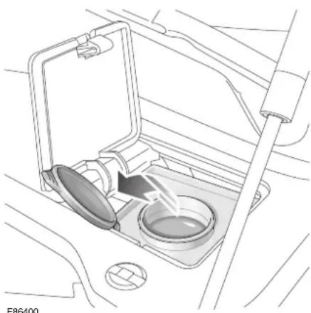
natural_image
Interior view of a car intake manifold with a lid and vent, showing no text or symbolsRefer to pages 216 for the washer reservoir location.

WARNING:
Some screen washer products are inflammable, particularly if high or undiluted concentrations are exposed to sparking. Do not allow screen washer fluid to come into contact with naked flames or sources of ignition.

WARNING:
If the vehicle is operated in temperatures below 4^ C ( 40^ F), use a washer fluid with frost protection. In cold weather, failure to use a washer fluid with frost protection, could result in impaired vision and increase the risk of a vehicle crash.
Caution: Do not use an antifreeze or vinegar/water solution in the washer reservoir - antifreeze will damage painted surfaces, while vinegar can damage the windscreen washer pump.
Caution: Body panels may suffer discolouration as a result of screen washer fluid spillage. Take care to avoid spillage, particularly if an undiluted or high concentration is being used. If spillage occurs, wash the affected area immediately with water.
The washer reservoir contains the fluid for the windscreen washers and the headlamp powerwash system (where fitted).
Fill to just below the neck with Jaguar Windscreen Washer Fluid diluted with clean, preferably soft water as specified in the instructions on the bottle.
Do not over-fill.
Note: Using a non-approved fluid may adversely affect the wiper blade rubber, resulting in ineffectual and noisy wiping.
Capacity
The windscreen washer reservoir capacity:
• without headlamp wash is 4.5 litres (7.9 Imperial pints).
• with headlamp wash is 7.1 litres (12.3 Imperial pints).
Cold weather precautions
To prevent damage to the pump during freezing conditions, use Jaguar Windscreen Washer Fluid at the strength shown on the bottle, for the anticipated ambient temperature.
Checking and Top-up
ENGINE COOLANT RESERVOIR
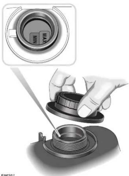
natural_image
Illustration of a hand using a tool to adjust a mechanical component, with an inset showing the top view of a device labeled 'MAX' (no text or symbols on the diagram itself)E86397
Refer to pages 216 for the engine coolant reservoir location.
The coolant level MAX and MIN indicators are located inside the reservoir and are only visible when looking into the filler neck with the cap removed. Check the level only when the engine is cold.
The coolant level should be between the MAX and MIN indicators. If persistent coolant loss is noticed, have a Jaguar Dealer/Authorised Repairer investigate the cause immediately.
Caution: Running the engine without coolant will cause serious engine damage.
Topping up
WARNING:
Never remove the filler cap when the engine is hot - escaping steam or scalding water could cause serious personal injury.
WARNING:
Avoid spilling antifreeze onto a hot engine - a fire may result.
WARNING:
Unscrew the filler cap slowly, allowing the pressure to escape before removing completely.
WARNING:
Do not allow anti-freeze to make contact with skin or eyes. If this happens, rinse the affected area immediately with plenty of water.
Caution: When travelling in territories where the water supply contains salt, always ensure you carry a supply of fresh (rain or distilled) water. Topping up with salt water will cause serious engine damage.
Caution: Anti-freeze will damage paintwork. Avoid spillage.
Top up with a mixture of 50% water and 50% antifreeze until the coolant is between the MAX and MIN indicators inside the header tank. Use anti-freeze to specification WSS M97B44, coloured orange, Extended Life Coolant. This 50/50% mixture gives frost protection for temperatures down to -40^ C ( -40^ F).
Checking and Top-up
Do not mix any other antifreeze with that specified; inferior quality antifreeze may be ineffective in maintaining adequate frost and corrosion protection to the cooling system.
Refit the filler cap and hand-tighten securely until the ratchet operates.
Engine antifreeze

WARNING:
Antifreeze is poisonous and can be fatal if swallowed - keep containers sealed and out of the reach of children. If accidental consumption is suspected, seek medical attention immediately.

WARNING:
If the fluid comes into contact with the skin or eyes, rinse immediately with plenty of water.
Caution: The use of non-approved antifreeze will have an adverse effect on the engine cooling system and therefore engine durability.
Caution: Antifreeze will damage painted surfaces; soak up any spillage with an absorbent cloth immediately and wash the area with a mixture of car shampoo and water.
When used at the correct concentration, antifreeze not only protects the engine from frost damage in winter, it also provides all year round protection against internal corrosion.
The coolant solution may remain in the cooling system for five years or 250,000 km (156,000 miles) after which the system should be drained, flushed and refilled.
Engine block heater
Diesel engines are more difficult to start when the ambient temperature is very low. In geographical areas where temperatures below -10^ ( 14^ ) are experienced frequently, it is advisable to fit an engine block heater. The block heater will have an insulated connector at the front of the vehicle. Attach an extension cable to this connector and plug the other end into a 230/220 volt mains electricity supply socket. The heater can remain in use overnight if required. Typically, an engine block heater will use between 400W and 1000W per hour.
For further information consult your Jaguar Dealer/Authorised Repairer.
Caution: The fitting of an engine block heater does not eliminate the need for antifreeze.
Battery
BATTERY WARNING SYMBOLS
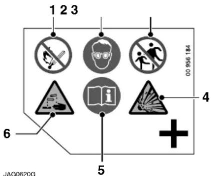
text_image
1 2 3 00 956 184 4 6 5 JAG0620GThere is a label on the battery (see illustration above) depicting a number of warning signs. The warning signs are as follows:
- No smoking, no naked flames, no sparks (Red).
- Shield eyes (Blue).
- Keep away from children (Red).
- Explosive gas (Yellow).
- Note operating instructions (Blue).
- Battery acid (Yellow).
BATTERY CARE
A low maintenance battery specifically designed for use with this vehicle is fitted below the luggage compartment floor.
In hot climates more frequent checks of the battery electrolyte level are required. If necessary, the battery cells can be topped up with distilled water.

WARNING:
Do not allow the battery electrolyte (fluid) come into contact with your skin or eyes. It is both corrosive and toxic, and the resulting injuries can be severe. If any electrolyte does come into contact with your skin or eyes, immediately rinse the affected area with clean, cold water. Immediate medical advice will be required.

WARNING:
If battery electrolyte comes into contact with your skin and/or clothes you should remove the affected clothing and flush the skin with copious amounts of water. Seek medical assistance immediately.

WARNING:
If battery electrolyte comes into contact with your eyes, flush with copious amounts of clean cold water. Seek medical assistance immediately, and continue to flush with water.

WARNING:
If swallowed, battery electrolyte can be fatal. If electrolyte is swallowed seek medical assistance immediately.

WARNING:
Do not connect any 12 volt equipment directly to the battery terminals. Doing so may cause a spark, which can result in an explosion.
Battery

WARNING:
The cell plugs and vent pipe must be in place at all times when the battery is connected to the vehicle. Ensure that the vent pipe is clear of obstructions and not kinked. Failure to do so may cause a pressure build up in the battery, resulting in an explosion.

WARNING:
Do not expose the battery to a naked flame or spark as the battery produces explosive, flammable gas.

WARNING:
Never jump start (boost) or charge, a frozen battery. Doing so can result in an explosion.

WARNING:
Remove all metal jewellery before working on, or near, the battery, and never allow metal tools or vehicle components to come into contact with the battery terminals. Metal objects can cause sparks, and/or short circuits, resulting in an explosion.

WARNING:
Do not allow the battery posts or terminals to come into contact with your skin. They contain lead, and lead compounds which are toxic. Always wash your hands thoroughly after handling the battery.
Caution: Do not allow battery electrolyte to come into contact with fabrics or painted surfaces. If battery electrolyte comes into contact with any surface, the surface should be washed down immediately with copious amounts of clean water. Battery electrolyte is both corrosive and toxic, and can damage a wide range of materials if left.
The exterior of the battery should be occasionally wiped clean to remove any dirt or grease.
If a new battery is to be fitted, it must be the same type as the original.
The use of unapproved batteries is not recommended and could invalidate the vehicle warranty.
Note:
The service life of the battery is dependent on its condition of charge. It must always be sufficiently charged for the battery to last an optimum length of time.
ALTERNATOR
To prevent damage to the alternator, do not run the engine while the battery or any of the charging circuit cables are disconnected.
The alternator has polarity-sensitive components that will be irreparably damaged if subjected to incorrect polarity. Ensure that the battery earth lead is always connected to the battery negative terminal.
Battery
BATTERY LEAD DISCONNECTION AND RECONNECTION
Battery lead disconnection

natural_image
Technical illustration of an automotive battery pack with wiring and mounting bracket (no text or symbols)Caution: Under no circumstances should a battery be disconnected whilst the ignition circuit is live, as permanent damage to the instrument panel may occur.
Caution: Disconnect the negative lead (earth terminal) first.
Fold the luggage compartment floor panel forwards.
Slacken the negative lead pinch bolt and disconnect the negative (−) battery lead. Slacken the positive lead pinch bolt and disconnect the positive (+) battery lead.
Battery lead connection
Note: Upon battery reconnection the security system will be armed. Opening any protected entry will sound the alarm. Make sure that a key or key transmitter is available.
Caution: Do not over-tighten the pinch bolts.
Clean the battery posts and coat the post bases with petroleum jelly.
Ensure the vent tube is connected and free from kink or damage.
Connect the positive (+) lead, tighten the pinch bolt and clip the positive terminal cover on the battery. Connect the negative (−) lead and tighten the pinch bolt.
After the battery has been reconnected and the ignition switch is turned to position II, the message centre display will initially show an erroneous reading i.e.
- - - - - . This will remain until after the bulb check sequence, when the correct recorded distance will be displayed. This is a normal function of the instrument panel.
After battery reconnection
After reconnecting the battery:
- Reset the Electric Parking Brake (EPB); see page 124.
- Reset the electrically operated windows anti-trap function; see page 78.
- The trip computer will lose all recorded trip data and all trip functions will be reset to zero. The vehicle total odometer reading is retained.
- The radio will not operate until the correct security code has been re-entered. Refer to the audio systems handbook or the touch-screen display handbook.
- If the battery is disconnected for more than 72 hours the radio preset channels will need to be reset.
Battery
- Where fitted, the TV preset channels may need to be reset. Refer to the touch-screen display handbook.
- Reset the clock to the correct time.
The engine electronic control system adapts to certain characteristics of the vehicle. These adaptations are lost if the battery is disconnected.
On reconnection, therefore, some slightly abnormal drive symptoms may occur and the vehicle may need to be driven 16 kilometres (10 miles) or more while the control system re-adapts.
BATTERY CHARGING

WARNING:
Ensure that the charger used is of the correct type and rating for the battery. Using an unsuitable charger may damage the battery, and could cause the battery to explode.

WARNING:
Batteries produce combustible gas (hydrogen) when being charged. The battery must be removed from the vehicle before charging commences.

WARNING:
Never charge or boost a frozen battery.

WARNING:
Always charge the battery in a well ventilated area away from any naked flames, sparks or other ignition sources. During charging the battery can produce a highly explosive and flammable gas.
Caution: The battery must be disconnected and removed from the vehicle before charging. Failure to do so could result in damage to the vehicle's electrical system.
Caution: Always follow the instructions supplied with the battery charger. Failure to do so may result in damage to the battery.
To disconnect the battery, refer to Battery lead disconnection on page 228.
When charging the battery ensure that the charge voltage is the same as the nominal voltage of the battery.
Switch off the charger before connecting or disconnecting terminal connections to avoid sparks and short circuits.
Ensure that the charger positive (+) lead is connected to the positive (+) terminal of the battery and the negative (−) lead is connected to the negative (−) terminal of the battery.
Do not remove or loosen any of the cell plugs when charging the battery.
WINDSCREEN WIPER BLADES
Inspect and clean
Lift the wiper blades clear of the windscreen and wipe the blades with a clean, soft cloth moistened with water to which a mild liquid detergent has been added.
Use Jaguar Screen Clean Paste to remove contamination from the windscreen to ensure effective wiping or if smearing or juddering becomes evident.
A more aggressive cleaning agent may be required to remove stubborn contamination. Contact a Jaguar Dealer/Authorised Repairer for advice.
To ensure that the windscreen remains smear-free, the washer system should be operated whenever the wipers are used, even when it is raining.
BLADE REPLACEMENT
As the windscreen washer jets are mounted on the wiper arms, it is recommended that the wiper blades are changed by a Jaguar Dealer/Authorised Repairer.
Caution: Only fit the correct length and type of wiper blade. Failure to do so may cause damage to the wiper system, it may also affect the operation of the rain sensor.
Note: The windscreen washer jets and headlamp washer jets are not adjustable.
Wheels and Tyres
TYRE CARE
Tyre pressures

WARNING:
Improperly inflated tyres can affect vehicle handling and can fail suddenly, possibly resulting in loss of vehicle control.
Caution: Never exceed the maximum pressure stated on the sidewall. Over-inflation could cause the tyre to fail suddenly.
Note: It is an offence in certain countries to drive a vehicle with tyres that are not inflated in accordance with the vehicle's proper use.
The recommended tyre pressures are written on a label, inside the fuel filler flap. These tyre pressures provide optimum ride and handling characteristics for all normal operating conditions.
In the interest of safety, reliability and fuel efficiency, check the tyres, including the spare, for condition and pressure on a weekly basis.
Pressure checks must be carried out when the tyres are cold and the vehicle has been standing in ambient local conditions for at least one hour.
Do not check tyre pressures immediately after the tyres have travelled a distance of one mile or more. Tyre temperatures and pressures increase when running.
Deflating a warm tyre to the recommended pressure will result in under-inflation. This could be dangerous.
If tyre pressures are checked while the vehicle is inside a protected covered area, e.g. a garage, and subsequently driven in lower outdoor temperatures, tyre under-inflation could occur.
A slight pressure loss occurs naturally with time. If this exceeds 14 kPa (2 lbf/in ^2 , 0.14 bar) per week, have the cause investigated and rectified by a qualified technician.
Ambient temperature pressure compensation
If the intended journey will take the vehicle into an area where the ambient local temperature is known to be lower than the journey start point, tyre pressure under inflation could occur.
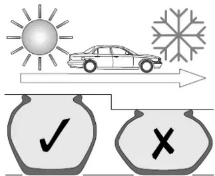
text_image
Weather and transportation diagram showing sun, car, snowflake, checkmark, and cross symbols for vehicle inspectionE86402
A colder ambient local temperature will reduce pressure within the tyre. An effect is to decrease sidewall height and to increase tyre shoulder wear with the potential for tyre failure. Vehicle dynamics could also be adversely affected.
Wheels and Tyres
In order to minimise this effect, tyre pressures can be adjusted to compensate before the start of the journey. Alternatively, tyre pressures can be adjusted when the area of lower ambient temperature is reached.
In this situation the vehicle must be left in the ambient local temperature for a least one hour before tyre pressure is adjusted.
To compensate for colder ambient temperatures, tyre pressures should be increased by 2lbf/in ^2 (0.14 bar / 14 kPa) for each 10°C (20°F) decrease.
Note: Ensure that correct tyre pressures are maintained when moving to areas of differing ambient temperature.
The Tyre Pressure Monitoring system (TPM system) may issue a warning if the under-inflation becomes significant. When driving through variable climatic conditions the TPM system warnings may be intermittent.
In areas of extended high ambient temperature, vehicle tyres can be affected by a softening of the tyre sidewall. If the vehicle is stationary for long periods, the effect is to slightly deform the tyre at the point where the tyre meets the standing surface. This is known as a flat spot.
This is normal tyre behaviour, however, when the vehicle is subsequently driven, vibration may be experienced from the deformed tyre. The condition will steadily improve with additional mileage.
In order to minimise this effect, tyre pressures can be adjusted before the start of the journey to compensate.
For each 10^ C ( 20^ F) increase in temperature above 20^ C ( 68^ F), tyre pressure should be increased by 2lbf/in (0.14 bar / 14 kPa).
2
Tyre pressure compensation chart - high ambient temperatures
Tyre Pressure Temperature Compensation
| Ambient Temperature °C (°F) | Pressure Compensation lbf/in2(bar/kPa) |
| 20 (68) use placard label | |
| 30 (86) +2 (0.14 / 14) | |
| 40 (104) +4 (0.28 / 28) | |
| 50 (122) +6 (0.41 / 41) | |
Wheels and Tyres
Tyre pressures during long term vehicle storage
To minimise the possibility and effects of flat spots during storage, the tyres may be inflated to the maximum pressure indicated on the tyre wall.
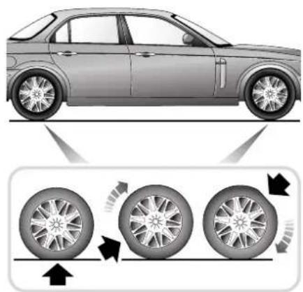
natural_image
Side view of a sedan with wheel rim and tire diagram illustrating tire movement (no text or symbols)JAG0653
Note: Before using the stored vehicle on the road again, ensure that correct tyre pressures are restored.
Wheels and Tyres
Wear

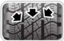
All tyres fitted as original equipment include Tread Wear Indicators (TWI) in their tread pattern. When the tread has worn to a remaining depth of 1.6 mm the indicators appear at the surface as bars which connect the tread pattern across the full width of the tyre.
It is illegal, in certain countries, to continue to use tyres after the tread has worn to less than 1.6 mm over three quarters of the width and the entire circumference of the tyre.
It should be noted that the properties of many tyres alter progressively with wear. In particular, the wet grip and aquaplaning resistance are gradually but substantially reduced. Extra care and speed restriction should therefore be exercised on wet roads as the effective tread depth diminishes.
Incorrect wheel alignment will accelerate tyre wear. If there is wear on the inner or outer edges of the tread pattern it will be advantageous to have the cause detected by having the wheel alignment checked.
Do not interchange tyres from side to side, front to rear or vice versa.
Damage
Excessive local distortion can cause the casing of a tyre to fracture and may lead to premature failure. Tyres should be examined especially for cracked walls, exposed cords, etc. Flints and other sharp objects must be removed from the tyre tread; if left in they may work through the cover. Clean off any oil or grease contamination by using a suitable cleaner.
Caution: Do not use paraffin (kerosene), because this has a detrimental effect on rubber.
Tyre repair
Damaged tyres should be replaced with new tyres fitted. They must not be repaired in view of the high performance capability of the vehicle.
Tyre replacement
When replacing tyres, it is preferable to fit a complete vehicle set. If either front or rear tyres only need to be renewed, new tyres must be fitted as axle sets.
After new tyres have been fitted the wheels need to be dynamically balanced.
Do not fit tyres with a different tread pattern, size or speed rating.
The installation of replacement tyres with steel cord body plies in the tyre sidewall may cause malfunction of the TPM system and is not recommended (cord material information is moulded on the tyre sidewall).
Additionally, if your vehicle was equipped with run-flat tyres, replacing them with tyres that are not identical to those originally fitted may cause malfunction of the TPM system, and is not recommended.
Wheels and Tyres
Always check your TPM system indicator after replacing one or more tyres on your vehicle.
Tyre ageing
Tyres degrade over time, even when they are not being used. It is recommended that tyres generally be replaced after six years of normal service. Heat caused by hot climates or frequent high loading conditions can accelerate the ageing process.
You should replace the spare tyre when you replace the other road tyres due to the ageing of the spare tyre.
TYRE PRESSURE MONITORING

WARNING:
The Tyre Pressure Monitoring (TPM) system is NOT a substitute for manually checking tyre pressures. Tyre pressures, including the spare wheel, should be checked regularly, when cold, using an accurate pressure gauge and inflated to the correct pressure. Failure to properly maintain your pressures could increase the risk of tyre failure, with consequential loss of vehicle control and personal injury.

WARNING:
The TPM system cannot register damage to a tyre. Regularly check the condition of your tyres.
Note:
- Non-approved accessories may interfere with the system. If this occurs, TYRE PRESSURE SYSTEM FAULT is displayed in the message centre.
- Certain tyres may affect the performance of the TPM system. Always replace tyres in accordance with recommendations, see page 231.
Your vehicle may be equipped with a TPM system which monitors pressure in each tyre (temporary-use spare wheels are not fitted with sensors and are consequently not monitored).
Wheels and Tyres

natural_image
Technical illustration of two mechanical components with numbered parts (1 and 2), no visible text or symbolsWheels fitted with a TPM system can be easily visually identified by the external metal lock nut and valve (1). All Jaguar non-TPM system wheels have a rubber valve fitted (2).
Vehicle speed
If a vehicle is to be driven at speeds above 160 km/h (100 mph), the tyre pressures must be set to the recommended higher pressure stated on the tyre pressure label. If this is not carried out, the TPM system will display the message TYRE
PRESSURES LOW FOR SPEED, the amber warning indicator within the panel and the AMBER priority warning indicator will be illuminated. In the event of this warning being displayed, the vehicle speed should be reduced.
Note: Always reset the tyres to Comfort pressures when speeds below 160 km/h (100 mph) are resumed.
TPM system operation
The TPM system monitors pressure of the tyres via sensors located in each wheel and a receiver located within the vehicle. Communication between sensor and receiver is via Radio Frequency (RF) signals.

The tyre pressure warning comprises the TPM warning indicator, see page 93, the
amber priority warning indicator and an associated message within the message centre, see page 99.
If a warning appears one or more of your tyres is significantly under-inflated. You should stop and check your tyres as soon as possible and inflate them to the recommended pressure see page 231. If warnings re-occur frequently, the cause must be determined and rectified.
Caution: When inflating tyres, care should be taken to avoid bending or damaging the TPM system valves. Always ensure correct alignment of the inflation head to the valve stem.
Driving with an under-inflated tyre causes the tyre to overheat and can lead to tyre failure. Under-inflation also reduces fuel efficiency and tyre tread life and may affect the vehicle's handling and stopping ability.
Wheels and Tyres
Your vehicle will also indicate a TPM system malfunction by initially flashing and subsequent continuous illumination of the warning tell-tale. A text message will accompany the system malfunction and will display TYRE PRESSURE
SYSTEM FAULT. When a malfunction occurs, the system may not be able to detect or signal low tyre pressure as intended. TPM system malfunctions may occur for a variety of reasons which may include other radio frequency systems that could cause interference or the fitting of non-recommended tyres.
Tyre pressures
To correctly set the tyre pressures, see page 231.
Spare tyre pressure: The full size spare tyre should be inflated to the highest pressure for the specified tyre size.
If a wheel and tyre needs changing
If the temporary-use spare wheel is fitted the system will automatically recognise the change in wheel positions. Then after approximately ten minutes of driving above 25 km/h (18 mph), a message
TYRE PRESSURE SENSOR FAULT will be displayed accompanied by illumination of the warning tell-tale and the amber priority warning indicator.
The warning telltale will initially flash and will subsequently revert to continuous illumination. Extended use of the temporary-use spare wheel will produce an additional text message TYRE
PRESSURE SYSTEM FAULT.
This TPM system display sequence will be activated at every ignition cycle until the temporary-use spare wheel is replaced by a fully operational full size wheel and tyre assembly.
Always replace the temporary-use wheel before having TPM system faults investigated. The fault may well be rectified with the fitment of a fully operational full size running tyre in lieu of the temporary-use spare wheel assembly.
Tyre changing
Always have your tyres serviced or changed by a qualified engineer.
Care must be taken to avoid contact between the bead of the tyre and the sensor during removal and refitting of the tyre, otherwise the sensor may become damaged and or inoperable.
Caution: Valve stem seal, washer, nut, valve core and cap should be replaced at every tyre change. Valve stem seal, washer and nut must be replaced if valve retention nut is loosened. Sensor units and nuts must be refitted using correct torque figures and associated profile. Damage to the vehicle may result if these precautions are not taken.
Sensors can be removed from the wheel by the unscrewing of the valve retention nut.
Replacement sensor
Should the sensor require replacing, it should be carried out by a Jaguar Dealer/Authorised Repairer.
A replacement sensor must be fitted to a running wheel in order to be recognised by the TPM system. Recognition only occurs when the vehicle is driven above 25 km/h (18 mph) for approximately ten minutes.
Wheels and Tyres
If the TPM system warning for any wheel does not clear, even after ensuring correct inflation and driving for more than ten minutes above 25 km/h (18 mph), you should seek qualified assistance as soon as possible.
Radio Frequency Approval
The TPM system transmitters and receivers meet European approval.
WINTER (SNOW) TYRES
The tyres fitted as original equipment are designed with a rubber compound, tread pattern and width specially suited for high speeds in normal road conditions, but they are less suitable during extremes of low temperatures, snow and ice. The use of winter tyres will considerably improve the vehicle's handling during these conditions.
It is recommended that only Jaguar approved winter tyres are used (see page 250).
Tyre directional indicators must be rotating in a clockwise direction when viewed from the right-hand side of the vehicle, and anti-clockwise when viewed from the left-hand side of the vehicle.
Do not exceed the tyre speed rating when using winter tyres.
Winter tyres must be used in vehicle sets, that is, fitted on all four wheels.
SNOW CHAINS
Snow chains, of the recommended type, may only be fitted to rear wheels.
Contact your Jaguar Dealer/Authorised Repairer for details and availability of approved snow chains.
The maximum speed when using snow chains is 48 km/h (30 mph).
Remove the snow chains immediately the roads are clear of snow.
Ensure the fitting instructions supplied with the snow chains are kept in a safe place, for example, with this literature pack.
Note: Dynamic Stability Control MUST be switched OFF when using snow chains.
Vehicle Care
VALET KIT
A valet kit containing a selection of Car Care products is available from the Jaguar accessory range.
INTERIOR CARE

WARNING:
Do not use chemical solvents or strong detergents when cleaning the steering wheel or instrument panel to avoid contamination of the airbag system. Do not use chemical solvents or strong detergents when cleaning the seat -mounted side airbags. Such products could contaminate the side airbag system and affect performance of the side airbag in a collision.
Brush and clean the interior regularly. Use a vacuum cleaner where possible to remove all dust from the interior and trim.
Carpets
Marks or stains can be removed by gentle scrubbing with a weak solution of soap and warm water.
For more stubborn stains a commercially available carpet cleaner should be used. See your Jaguar Dealer/Authorised Repairer for advice.
Headlining
Remove dust in the headlining with a vacuum cleaner. To remove stains, dab gently without pressing, using a fluff-free white cloth, moistened with Jaguar Upholstery Cleaner.
Do not use methylated spirit or solvents as this may cause damage or discoloration to the headlining.
EXTERIOR CARE
Note: All the cleaning materials mentioned in this section are available from the Jaguar Accessory Range.
Vehicle washing
For best results, do not wash the vehicle under strong sunlight. Always allow the vehicle to cool down before washing.
Do not use a dry cloth to wipe dirty paintwork. Dust and gritty substances are abrasive and will scratch the paintwork. Remove dirt using a cellulose sponge and plenty of warm (never hot) water. Rinse off with clean water and dry using a clean, damp chamois leather.
Do not use household soaps or detergents. The use of Jaguar Vehicle Shampoo is recommended.
Do not direct hoses at full force around door and luggage compartment seals. Using high pressure water jets on the paintwork is not recommended.
Do not allow bird droppings or tree sap to harden. Remove from paintwork immediately with a lukewarm soap and water solution.
In winter, when salt is used on the roads, wash the vehicle frequently, and immediately after encountering such conditions. Clean undersides and wheel arches using a high pressure jet.
Automatic car wash
Note: Regular use of automatic car washes tends to dull the lustre of the paintwork.
Vehicle Care
After leaving the car wash, switch on the windscreen wipers immediately to remove water and prevent a build up of wax. Jaguar Screen Clean Paste can be used to clean any residual wax from the glass.
Caution: Ensure the rain sensitive windscreen wipers are switched OFF before entering an automatic car wash, to prevent damage to the wiper blades/arms.
Removing grease or tar
Remove grease or tar with Jaguar Tar Remover or methylated spirit (alcohol). White spirit is also effective, but must not be applied to rubber, particularly the windscreen wiper blades.
Glass surfaces
To avoid scratching glass surfaces, do not clean dirty glass with dry paper or cloth. Use clean, warm water and a chamois leather which is reserved for glass only.
The following products will ensure glass surfaces and windscreen wipers are kept in good condition:
Jaguar Screen Clean Paste – Apply to the exterior of the windscreen only to ensure effective operation of the windscreen wipers.
Jaguar Glass Cleaner – Interior and exterior of all other glass surfaces.
Jaguar Screen Wash – Washer reservoir additive.
Jaguar Winter Care Kit comprising de-icer, ice scraper, anti-mist wipe cloth and aerial cleaner – for use in adverse weather conditions.
Note:
- Renew the wiper blades when worn to prevent scratching. Clean the rubber wiper blades regularly with a mild detergent solution.
- It is advisable to clean the windscreen with Jaguar Screen Clean Paste at regular intervals.
Cleaning the rear screen
To avoid damaging the heating and radio elements when cleaning the inside of the rear screen use only a soft, damp cloth or chamois leather. Do not use solvents or sharp objects to clean the glass.
Polishing paintwork and brightwork
For maximum protection against road dust, salts, industrial fall-out etc., it is recommended that the vehicle is polished regularly using Jaguar Polish and a Polishing Cloth.
Note: The vehicle's brightwork should be cleaned in the same way as the paintwork: Chrome polish or other abrasive cleaners must not be used.
Paint chips
Scratches and chips should be touched in before weathering action begins. Inspect the paintwork immediately after the vehicle has been washed.
Underbonnet cleaning
Underbonnet cleaning using high pressure hoses or steam cleaners should be done by a Jaguar Dealer/Authorised Repairer.
Indiscriminate use of cleaning equipment could damage or contaminate the electronic control modules and fuse boxes.
Vehicle Care
CARE OF ALLOY ROAD WHEELS
The alloy road wheels are covered with a protective anti-corrosion coating. To prevent corrosion it is essential that this coating is not damaged.
When removing or fitting tyres always advise the tyre fitter to treat the alloy wheels with great care and to only use equipment with spigot or stud hole clamping. The equipment must not have any moving parts which contact the wheel, and tyre levers must not be used.
Wash the wheels with soap and water at two week intervals to avoid an accumulation of particles which could become embedded in the wheel surface. In salty conditions the wheels should be cleaned weekly.
In compliance with German Road Traffic Law, the size of the wheel rims is stamped or cast on all wheels.

WARNING:
Alterations to the electrical system, including the fitting of accessories not designed for this Jaguar, will cause damage to the electrical circuits and systems. In some circumstances this could result in a malfunction or fire. All accessory work should be entrusted to a Jaguar Dealer/Authorised Repairer.
Caution: Under no circumstances must the power supply be obtained directly from either battery terminal.
Caution: The use of non-approved accessories can reduce the battery capacity and charge period to an unacceptable level, therefore, Jaguar cannot accept any liability for the fitment of any such item.
EARTH POINTS
If an accessory needs to be connected to an earth point, consult a Jaguar Dealer/Authorised Repairer.
Under no circumstances must holes be drilled in the bodywork to accept earth terminals.
Engine Data
ENGINE DETAILS
| Type V8, dual overhead | V8, dual overhead | |
| camshafts, 4 | camshafts, 4 | |
| valves/cylinder, naturally aspirated | valves/cylinder, supercharged | |
| Capacity | 4196 cm^3 (255 inch ^3 ) | 4196 cm^3 (255 inch ^3 ) |
Bore 86 mm (3.385 inch) 86 mm (3.385 inch)
Stroke 90.3 mm (3.555 inch) 90.3 mm (3.555 inch)
Compression ratio 11.0:1 9.1:1
| Type V8, dual overhead | V6, dual overhead | |
| camshafts, 4 | camshafts, 4 | |
| valves/cylinder, naturally aspirated | valves/cylinder, naturally aspirated | |
| Capacity | 3555 cm^3 (216 inch ^3 ) 2967 cm^3 (181inch ^3 ) | |
Bore 86 mm (3.385 inch) 89 mm (3.504 inch)
Stroke 76.5 mm (3.011 inch) 79.5 mm (3.130 inch)
Compression ratio 10.8:1 10.5:1
Engine 2.7 Litre Diesel
| Type V6, dual overhead | |
| camshafts,4 valves per cylinder | |
| Capacity | 2720 cm ^3 (166 inch ^3 ) |
Bore 81.0 mm (3.188 inch)
Stroke 88.0 mm (3.464 inch)
Compression ratio 17.3:1
*NA = Naturally aspirated engine
*SC = Supercharged engine
Dimensions
DIMENSIONS
SWB* LWB*
cm inch cm inch
Overall length 509.0 200.4 521.5 205.3
Overall width including mirrors 210.8 82.9 210.8 82.9
Overall width without mirrors 186.0 73.2 186.0 73.2
Overall height (at gross vehicle weight) 144.8 57.0 144.8 57.0
Wheelbase 303.4 119.5 315.9 124.4
Track:
Front 155.6 61.2 155.6 61.2
Rear 154.6 60.9 154.6 60.9
*SWB = short wheelbase
*LWB = long wheelbase
Weights
WEIGHTS (Average/Approximate)
Gross combination weight is the gross vehicle weight plus the recommended trailer weight.
Vehicles with 3.0 litre V6 engines
Short wheelbase Long wheelbase
kg lb kg lb
Kerb weight, no options fitted 1608 3545 1614 3558
Front axle kerb weight 812 1790 786 1733
Rear axle kerb weight 796 1755 828 1825
Mass in running order, all options fitted, 1807 3984 1830 4034 including 90% fuel and a 75 kg driver
Gross vehicle weight (GVW) 2183 4812 2206 4863
Gross front axle weight 1024 2257 1031 2273
Gross rear axle weight 1155 2546 1175 2590
Gross combination weight 4083 9001 4106 9052
Vehicles with 3.5 litre
V8 NA* engines
Short wheelbase Long wheelbase
kg lb kg lb
Kerb weight, no options fitted 1678 3699 1684 3711
Front axle kerb weight 857 1889 829 1828
Rear axle kerb weight 821 1810 855 1885
Mass in running order, all options fitted, 1875 4134 1898 4184 including 90% fuel and a 75 kg driver
Gross vehicle weight (GVW) 2225 4905 2248 4956
Gross front axle weight 1046 2306 1050 2315
Gross rear axle weight 1178 2597 1198 2641
Gross combination weight 4125 9094 4148 9145
*NA = naturally aspirated engine
*SC = SuperCharged engine
Weights
Vehicles with 4.2 litre
V8 NA* engines
Short wheelbase Long wheelbase
kg lb kg lb
Kerb weight, no options fitted 1678 3699 1684 3712
Front axle kerb weight 857 1889 849 1872
Rear axle kerb weight 821 1810 835 1841
Mass in running order, all options fitted, 1870 4122 1893 4173 including 90% fuel and a 75 kg driver
Gross vehicle weight (GVW) 2223 4901 2246 4951
Gross front axle weight 1048 2310 1050 2315
Gross rear axle weight 1176 2593 1196 2637
Gross combination weight 4123 9089 4146 9140
Vehicles with 4.2 litre
V8 SC* engines
Short wheelbase Long wheelbase
kg lb kg lb
Kerb weight, no options fitted 1728 3809 1734 3823
Front axle kerb weight 902 1988 884 1949
Rear axle kerb weight 826 1821 849 1872
Mass in running order, all options fitted, 1902 4193 1924 4242 including 90% fuel and a 75 kg driver
Gross vehicle weight (GVW) 2263 4989 2284 5035
Gross front axle weight 1063 2343 1079 2379
Gross rear axle weight 1200 2645 1205 2656
Gross combination weight 4163 9178 4184 9224
*NA = naturally aspirated engine
*SC = SuperCharged engine
Weights
Vehicles with 2.7 litre
V6 Diesel engines
Short wheelbase Long wheelbase
kg lb kg lb
Kerb weight, no options fitted 1727 3807 1733 3820
Front axle kerb weight 896 1975 912 2100
Rear axle kerb weight 831 1832 821 1810
Mass in running order, all options fitted, 1937 4270 1960 4321
including 90% fuel and a 75 kg driver
Gross vehicle weight (G.V.W.) 2294 5057 2317 5108
Gross front axle weight 1091 2405 1096 2416
Gross rear axle weight 1203 2652 1221 2692
Gross combination weight 4194 9246 4217 9297
ROOF RACK CAPACITY AND TRAILER WEIGHTS
kg lb
Roof rack capacity including weight of rack 75 165
Maximum permitted luggage compartment 60 132
load with four passengers and driver
Trailer weight:
Braked 1900 4189
Unbraked (maximum recommended) 750 1654
Trailer nose load 75 165
Loads greater than 60 kg (132 lb) may be carried in the luggage compartment provided the maximum permissible axle weights shown on the Vehicle Identification Plate are not exceeded and that tyres are inflated to the normal pressures.
Wheels and Tyres
The following chart details the tyres recommended for use in the markets listed below:
A. Australia, Bahrain, Egypt, Israel, Jordan, Kuwait, Lebanon, Malaysia, Mexico, Morocco, Oman, Qatar, Saudi Arabia, South Africa, Syria, Thailand, United Arab Emirates.
B. Argentina, Belarus, Brazil, Bulgaria, Chile, Dominican Republic, Estonia, Indonesia, Kazakhstan, Panama, Philippines, Romania, Russia, Sri Lanka, Ukraine, Uzbekistan.
| Tyre Size Pa t ter n A B | |||
| 235/50 ZR 18 97W Pirelli P6000 Powergy Yes Yes | |||
| 235/50 ZR 18 97W Continental premium Contact 2 Yes Yes | |||
| 255/40 ZR 19 96Y Pirelli P-Zero Yes No | |||
| 255/35 ZR 20 97Y Dunlop SP Sport 01 Yes No |
For all other markets, refer to your local Jaguar Dealer/Authorised Repairer for specific tyre fitment.
TEMPORARY-USE SPARE WHEEL
Pirelli 135/80 R18
Wheels and Tyres
WINTER TYRES
Recommended winter tyres are:
| Tyre Size Pattern | |
| 235/50 R 18 101V Continental Conti Winter Contact TS790 | |
| 235/50 R 18 101V Pirelli Snowsport 240 | |
| 235/50 R 18 101V Pirelli Sottozero W240 | |
| 245/45 R 19 102V Pirelli Snowsport 240 | |
| 255/45 R 19 102V Pirelli Sottozero W240 | |
TYRE PRESSURES
The tyre pressures recommended by Jaguar Cars to maintain optimum ride and handling characteristics for all normal operating conditions are shown on a label affixed to the inside of the fuel filler flap.
If you are unsure of the correct pressures please contact your Jaguar Dealer/Authorised Repairer.
TYRES NOT APPROVED BY JAGUAR

WARNING:
When using tyres other than those recommended by Jaguar do not exceed the speed capacity recommended by the manufacturer.
Fuel Consumption Figures
UNITED KINGDOM ONLY
(Miles per gallon)
| Vehicle Urban (cold) | Extra-urban Combined | |
| 3.0 Litre Petrol 17.8 | 37.9 26.9 | |
| 3.5 Litre Petrol 18.1 | 35.8 26.5 | |
| 4.2 Litre Petrol 16.9 | 33.8 24.8 | |
| XJR and Super V8 Petrol | 15.8 32.3 23.4 | |
| Diesel 26.0 43.7 35.0 |
Touch-screen
GENERAL INFORMATION
The touch-screen provides touch-control of vehicle climate, audio, navigation, television and telephone systems, as fitted. A small Liquid Crystal Display (LCD) screen below the touch-screen provides a digital display of the ambient temperature and vehicle cabin set temperature.
The touch-screen setup and user menus, clock setting, headlamp setting, door locking mode and auto-fold door mirrors information is described within this chapter of this handbook
Note: Remember to pass on the vehicle handbooks when reselling the vehicle. Handbooks are integral parts of the vehicle.
The buttons surrounding the touch-screen display are referred to as 'hard buttons' and should be pressed not touched. The screen buttons are 'soft buttons' and only require to be touched to function.
Throughout this section, the expression 'Select an item' (or similar wording), means 'Touch the on-screen button adjacent to the item required'.
Pop-up messages
The operation of certain functions will cause a small message to appear overlaying the touch-screen display. This ‘pop-up’ is for information only and will disappear automatically after a few seconds.
SCREEN CLEANING
Caution: Care must be taken to avoid spilling or splashing drinks onto the touch-screen. In the event of such an occurrence advise your Jaguar Dealer/Authorised Repairer.
Do not use any abrasive cleaners to clean your touch-screen. For approved screen cleaners, see your Jaguar Dealer/Authorised Repairer.
AUTOMATIC CLIMATE CONTROL
The climate control system can be controlled from the touch-screen buttons (accessed via the CLIMATE button to the left of the touch-screen) and is described in the Touch-screen Climate Control chapter of this handbook (starting on page 174).
Touch-screen
AUDIO SYSTEMS
The vehicle audio system interacts with the JaguarVoice, Navigation, In-car Telephone and Climate Control systems via data on the multiplex communications vehicle network.
The audio system can be controlled from the radio front panel buttons, the touch-screen buttons accessed via the
AUDIO button on the left of the touch-screen and from multi-function controls on the left-hand side of the steering wheel, where fitted. These controls are described in the Audio
System chapter of this handbook (starting on page 260).
The sound system antenna is an integral part of the vehicle rear screen and serves both FM and AM radio wavebands.
Audio security code number
For the United Kingdom and European countries, the audio head unit is protected by an anti-theft security code. If power to the radio drops to 5 volts or less (dead battery), or there is a power interruption/disconnection, the touch-screen display will indicate Enter System PIN. At this point the radio will not operate until the correct security code is re-entered.
The four-digit code, which is listed on an audio security card supplied with the vehicle, is entered by pressing the appropriate numeric buttons 0 to 9 displayed on the touch-screen followed by the ENTER button.
If the code is entered incorrectly, two further attempts at code entry will be permitted. If, after three successive attempts, the code has not been properly entered, the display will indicate PLEASE WAIT. In this condition the radio will not accept further entries until it has been left on for at least 30 minutes. After 30 minutes in the ON position the radio will accept three further entries
Note: In the event of loss of your radio security card, contact your Jaguar Dealer who, for security reasons, will require proof of vehicle ownership.
Touch-screen
NAVIGATION SYSTEM
This Jaguar navigation system assists the driver by providing a route to a selected destination. Guidance is given by means of audible instructions (voice guidance), complemented by map and turn information, which is displayed on the touch-screen. Digital map information is held on the Navigation System Digital Versatile Disc (DVD), which is loaded into the navigation control unit housed in the luggage compartment.
The system has an extremely comprehensive range of features, yet is easy to use. Some time spent reading the separate navigation system handbook will ensure that the best results are obtained.
The touch-screen is used to control the system by means of menus, text screens and map displays.
WARNING:
The navigation Database reflects reality as existing before you received the Database and it comprises data and information from government and other sources, which may contain errors and omissions. Accordingly, the Database may contain inaccurate or incomplete information due to the passage of time, changing circumstances, and due to the nature of the sources used. The Database does not include or reflect information on – amongst other things – neighbourhood safety; law enforcement; emergency assistance; construction work; road or lane closures; vehicle or speed restrictions; road slope or grade; bridge height, weight or other limits; road or traffic conditions; special events; traffic congestion; or travel time.
WARNING:
Only operate, adjust or view the system when it is safe to do so.
Touch-screen
TELEVISION SYSTEM
The TV tuner provides TV viewing when the vehicle is stationary or moving slowly.
TV is only available in certain countries. The TV system is described in the Television chapter of this handbook (starting on page 293).
IN-CAR TELEPHONE
The telephone is described in the separate in-car telephone handbook.
JAGUARVOICE
JaguarVoice provides a safe and convenient way for the driver and/or rear occupants to control the following vehicle systems (where fitted):
- Sound system (radio, CD player and CD changer – as applicable).
- In-car telephone.
- Climate control system (front user only unless 4-zone climate control is fitted).
- Television and Teletext.
• Display screen (front user only). - Navigation (front user only).
The system is controlled in the front of the vehicle by the steering wheel voice button, and, when fitted in the rear of the vehicle by the rear multimedia switchpack voice buttons, see the Voice Control chapter of this handbook (starting on page 323).
REAR MULTIMEDIA
For details of this system, see the separate rear multimedia handbook.
WINDOW TINTING

WARNING:
Do not have your vehicle windows tinted with a metal oxide tinting (for maximum heat reduction from sun load) if you have a Navigation system fitted to your vehicle.
Metal oxide tinting prevents the reception of the Global Positioning Satellite (GPS) signals by the antenna causing the navigation system to stop functioning.
A non-metal tinting should be used if you require window tinting and if in doubt, contact your Jaguar Dealer for advice.
Touch-screen Display
TOUCH-SCREEN DISPLAY
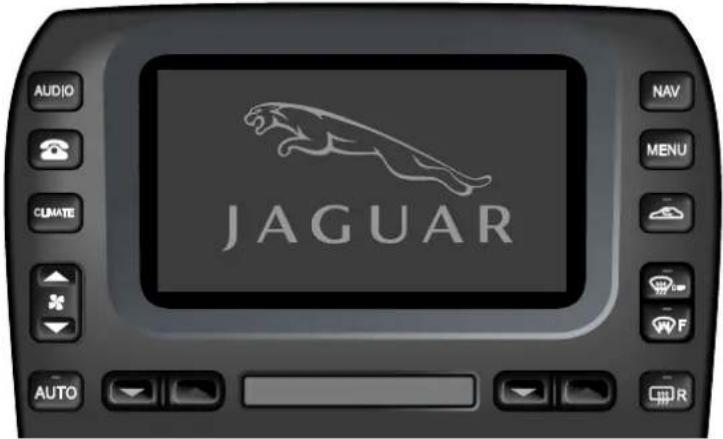
text_image
AUDIO JAGUAR NAV MENU CUMATE AUTOJOL4764
TOUCH-SCREEN USE AND CARE
When the ignition switch is initially turned to position I or II, the touch-screen will display the Jaguar logo screen followed by activation and display of the mode previously used. Display of buttons for other systems can be obtained by pressing the appropriate perimeter button. Functions of the MENU button are described on the following pages.

WARNING:
In the interests of road safety, only operate, adjust or view the system when it is safe to do so.
Caution: Care must be taken to avoid spilling or splashing drinks onto the screen. In the event of such an occurrence advise your Jaguar Dealer.
Note: When operating touch-screen buttons, always extend the tip of one finger, and withhold the thumb and remaining fingers from the screen. Touching the screen with more than one finger at a time may cause false inputs.
The touch-screen and inner bezel must be kept clean to maintain optimum performance. Finger marks and attracted dust should be regularly removed using a soft cloth and a Jaguar approved cleaning agent.
Touch-screen Display
MENU
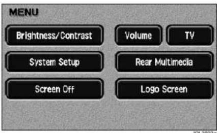
text_image
MENU Brightness/Contrast Volume TV System Setup Rear Multimedia Screen Off Logo ScreenPressing the MENU perimeter button will display the system menu screen.
The screen display can be blanked out by touching the Screen Off button.
Touch the screen, or press any of the perimeter buttons, to restore the display.
VOLUME PRESET

text_image
VOLUME PRESET OK NAV AVC TA PHONE VOICEAfter touching the Volume button, the screen displays the buttons for adjustment of volume associated with the navigation system, JaguarVoice, telephone, Traffic Announcements (TA) and Automatic Volume Control (AVC). Adjustment of AVC varies the rate at which volume is increased or decreased relative to vehicle speed.
Touch or hold the + or - button to adjust the volume of the selected function.
Note: If any of the volume slides are adjusted to the fully - position, then the volume is turned fully off.
Confirm your selection by touching OK and the system menu screen will once again be displayed.
Touch-screen Display
BRIGHTNESS/CONTRAST

text_image
BRIGHTNESS / CONTRAST Day Night Twilight Ent Dest. Store PO OK Auto Default OK JOL 2555After touching the Brightness/Contrast button, the screen displays the buttons for adjustment of the screen display characteristics. The centre window shows the currently selected navigation view.
Touch the + or - button to adjust the selected function.
Screen brightness and contrast can also be dimmed for night driving. This is achieved either manually via the Day, Night or Twilight buttons (independent of the exterior light master switch position), or automatically via the Auto button (controlled by the exterior light master switch position).
Touch the Default button to restore the default settings.
Confirm your selection by touching OK.
SYSTEM SETUP
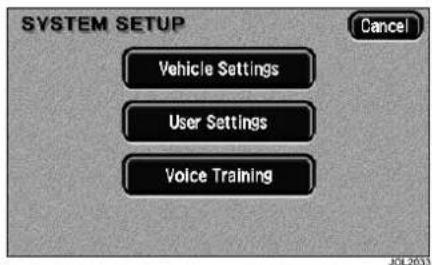
text_image
SYSTEM SETUP Vehicle Settings User Settings Voice Training Cancel JOL2033After touching the System Setup button, the screen displays the buttons for selecting user settings or vehicle settings.
Note: Vehicles which have the JaguarVoice system fitted will have an additional button on the system setup screen for voice training.
Touch-screen Display
User settings
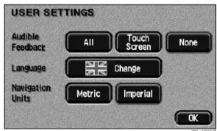
text_image
USER SETTINGS Audible Feedback All Touch Screen None Language Change Navigation Units Metric Imperial OKAfter touching the User Settings button, the screen displays the buttons for the selection of audible feedback, language, and units of measurement.
All selects audible feedback on the perimeter buttons and touch-screen buttons. Touch Screen selects audible feedback on the touch-screen buttons only. None selects no audible feedback.
To select another language, touch the Change button and, if the language is not shown, scroll the screen as required. To select a language, touch the flag of the country required.
Navigation Units provides either imperial or metric units for use with the navigation system.
Confirm your selection by touching OK.
Vehicle settings
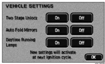
text_image
VEHICLE SETTINGS Two Stage Unlock On Off Auto Fold Mirrors On Off Daytime Running On Off Lamps New settings will activate at next ignition cycle. OKAfter touching the Vehicle Settings button, the screen displays the buttons that switch certain functions on or off.
Two-stage unlock
If this function is switched on, the first press of the key transmitter 'unlock' button will only unlock the driver's door. Press the unlock button a second time to unlock the remaining doors.
If the function is switched off, pressing the unlock button once will unlock all of the doors.
Auto fold door mirrors
When this function is switched on, the door mirrors will automatically fold flat when global closing is performed (refer to Security and Locks chapter of the Owner's Handbook).
Daytime running lamps
Where fitted, daytime running lamps will be activated. It is particularly useful when visiting countries where daytime running lamps are compulsory.
Audio System
GENERAL INFORMATION
The vehicle Audio system interacts with the in-car Phone system via data on the multiplex communications vehicle network.
The audio system can be controlled from either the radio panel or multi-function controls on the left-hand side of the steering wheel.

WARNING:
Sustained exposure to high sound levels can damage your hearing.
The sound system antenna is an integral part of the vehicle backlight and serves FM, AM, and DAB radio wavebands.
Caution: Care must be taken to avoid spilling or splashing drinks onto the audio system head. In the event of such an occurrence advise your Jaguar Dealer/Authorised Repairer.
Do not use petrol, solvents or abrasive cleaners on the audio system. Wipe the surface with a lint-free cloth to remove dust. Slightly moisten the cloth with clean water to remove any finger marks from the outside surface.
If the unit is to be removed or the battery disconnected, first ensure that the radio code is recorded. The number will be required for re-insertion following radio installation.
SECURITY CODE NUMBER
For the United Kingdom and European countries, the audio head unit is protected by an anti-theft security code. If power to the radio drops to 5 volts or less (dead battery), or there is a power interruption/disconnection, the radio display will indicate CODE. At this point the radio will not operate until the correct security code is re-entered.
The four-digit code which is listed on an audio security card supplied with the vehicle, is entered by pressing preset buttons 1 to 9. A beep indicates that the code has been entered correctly.
If the code is entered incorrectly, two further attempts at code entry will be permitted. If, after three successive attempts, the code has not been properly entered, the display will indicate PLEASE WAIT. In this condition the radio will not accept further entries until it has been left on for at least 30 minutes. After 30 minutes in the On position the radio will accept three further entries.
Note: In the event of loss of your radio security card, contact your Jaguar Dealer/Authorised Repairer who, for security reasons, will require proof of vehicle ownership.
Audio System
COPYRIGHT LAWS
Caution: Copyright laws vary in different countries; please check the laws in your country if you want to record from copyright source material.
Caution: Due to technical incompatibility, recordable (CD-R) discs and re-writable (CD-RW) discs may not function correctly.
Caution: These CD units will play compact discs that conform to the international Red Book standard audio specification. Copy protected CDs from some manufacturers do not conform to this standard and playback cannot be guaranteed.
Caution: Dual format, dual sided discs (DVD Plus, CD-DVD format), now being adopted by the music industry, are thicker than normal CDs and consequently playback cannot be guaranteed in Jaguar audio units, and jamming could occur. Warranty claims, where this type of disc is found to be inside an audio unit returned for repair, will not be accepted.
Caution: Irregular shaped CDs and CDs with a scratch protection film or self adhesive labels attached should not be used.
DUAL AND DVDPLUS DISCS
Please be aware that a new generation of DVDs is being adopted by the music industry. They are known as Dual Discs or DVDPlus discs. They have digital music on one side and video content on the other. Current in-car audio systems with a front loading CD player may load and play this type of disc, however, it is possible that the disc will not eject and therefore block up the player. Such damage to a CD player will not be covered under warranty.
AUDIO SYSTEM CARE
Radio
Do not use petrol, solvents or abrasive cleaners on the radio. Wipe the surface of the radio with a lint-free cloth to remove dust. Slightly moisten the cloth with clean water to remove any finger marks from the outside surface of the radio.
If the radio is to be removed or the battery disconnected, first ensure that the radio code is recorded. The number will be required for re-insertion following radio installation or battery reconnection.
Compact Discs (CDs)
When handling CDs, do not touch the playing surface. CDs should be stored in their cases away from direct sunlight, heat and dust. Scratches, fingermarks or dust on the surface of a disc can cause the optical pick-up to skip tracks. If the surface of a CD is dirty, use an appropriate CD cleaner.
Do not attempt to play discs that are damaged, warped, cracked or of incorrect size. They can seriously damage the playback mechanism.
Steering Wheel Controls
STEERING WHEEL CONTROLS
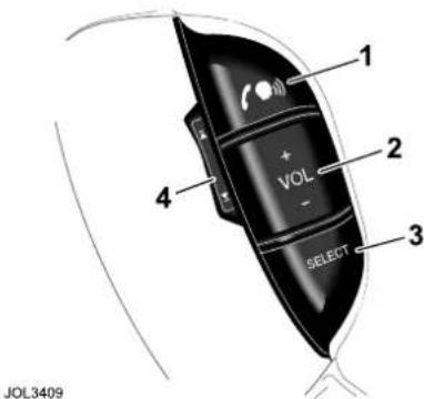
text_image
1 + VOL - SELECT 2 3 4 JOL3409Four audio system control switches are situated on the left-hand side of the steering wheel. Duplicating the functions of buttons on the audio panel, these provide fingertip control of audio and telephone systems whilst driving.
-
Press to start a voice session, or mute when JaguarVoice is not fitted. Answer phone call when ringing. Send/End when in phone mode.
-
Press as required to increase or decrease volume.
-
Press and release to cycle through Radio FM, AM, CD and CD Changer, or press and hold for at least two seconds to select Phone Ready mode.
-
Press as required and release to cycle through preset radio stations, the next CD track.
Press and hold for at least two seconds to cycle to next strong station or next CD.
Radio
GENERAL INFORMATION
Reception
FM reception offers the advantages of low noise interference, minimal distortion, wide dynamic range, extended frequency response, and is usually broadcast in stereo. FM frequency waves are however relatively short and travel in a straight line and can therefore be impeded by obstructions, which may adversely affect reception in certain parts of the country. This is a condition known as Multipath Interference.
Whilst FM reception generally provides better quality sound, AM reception or Medium Waveband (MW) and Long Waveband (LW) (United Kingdom and Europe) may prove superior in remote areas not covered by the shorter range FM transmitters.
When experiencing poor FM reception, background noise can be reduced by pressing the MODE button, selecting TREBLE and reducing the treble setting.
Radio Data Systems (RDS) and Traffic Announcements (TA)
Jaguar sound systems are equipped with Radio Data System (RDS) which assists in locating and remaining tuned to a selected radio station. When tuned to certain stations on the FM waveband, the radio decodes signals transmitted, to provide the following functions (dependent upon the service available):
- When RDS is selected the station name is displayed in eight characters.
• Automatic retuning to follow network stations:
RDS provides fully automatic radio tuning for network stations. It tunes to a signal not a frequency. RDS will locate the strongest signal available for a given station.
- RDS will automatically switch frequencies (AF Switching) as necessary. This function can be toggled off and on by pressing and holding the AM/FM button.
- RDS Station/Programme type display and search:
RDS displays information on the type of material broadcast by the station or programme that is on e.g. News,
Classical, Rock etc. In addition to this function, the radio can search for a selected programme type.
Radio
- RDS Priority Programme Type auto retuning (where broadcast):
Similar to Traffic Announcement this can be selected to interrupt and switch to the selected programme type e.g. News, for its duration. - Local radio station Traffic Information (where broadcast):
RDS provides travel information relevant to the vehicle location. On learning of a traffic problem, the authorities inform the nearest local radio station.
The traffic announcement (TA) is then broadcast by transmitters in the relevant area.
Provided TA has been selected, traffic announcements will interrupt radio or CD play, on all equipment with the RDS feature. If the volume control is set at minimum it will automatically increase to an audible level for the duration of the traffic news flash.
When the traffic announcement has been completed, the system reverts to the driver's original listening choice and volume setting.
RDS operation

To activate RDS, press the TA button and hold for at least two seconds until RDS ON is displayed.
To deactivate RDS, press the TA button and hold until RDS OFF is displayed.
With the radio tuned to an RDS station and RDS activated, the radio gathers RDS information and displays the service name/data.
If the radio is not tuned to an RDS station, it will remain on that station and display the frequency, and RDS will remain on in readiness for a signal.
When listening to a national network station, or a station that broadcasts on more than one frequency, the radio will return to the strongest available signal (AF Switching). This ‘network following’ will continue throughout the journey. (Unselected presets will also receive new frequency information, if appropriate.)
When RDS data is lost and no alternative frequency signal is available, the radio will stay on station, the display shows the frequency only and RDS remains on in readiness for the signal to recover.
If the RDS function does not respond correctly, see RDS troubleshooting guide on page 267.
Radio
TA operation
To activate TA: Press the TA button momentarily (less than two seconds).
TA will appear in the display. The radio then checks that the station has RDS TP (Traffic Programme); indicated by TP at the top of the display. If TP is not available on the current station, the display will show TP SEEK while it searches for a station that does have it.
If a TA station is not available, a beep is sounded and TA is removed from the display.
With TA activated, traffic announcements will interrupt radio or CD play. If set at a minimum, the volume will increase for the announcement, returning to normal setting afterwards. When receiving, the display will show TRAFFIC INFO.
To deactivate TA: Momentarily press TA.
Preset TA volume
When the radio is set to minimum volume and a traffic announcement occurs, the volume is raised to a preset level. This level can be adjusted by pressing and holding the MODE button for more than two seconds, then setting the volume level (which is displayed) between 1 (min.) and 6 (max.) by turning the volume control knob.
Programme Type (PTY)
(Where broadcast)

This has two functions: To display current station programme type and to select a programme type and return to it.
Momentarily press the PTY button to display the current station programme type. Use the tuning buttons to cycle through the available programme types, press the PTY button again to activate a search for the selected programme type. If there is a station with the correct PTY then the radio will return to it. If not, the radio will indicate NO PTY and return to the current station.
Priority Programme Type (PPTY)
Functions as an interrupt or as a 'PTY Following'.
Press and hold the PTY button to activate the selected priority programme type, PPTY. The radio will now wait for RDS information to indicate that a station has changed its programme type, e.g. to NEWS. The radio will now return to the new station for the duration that it remains on that programme type.
If the current station is already on the selected priority programme type, then when this station is lost, the radio will attempt to find another with the correct programme type.
To cancel Priority Programme Type, press and hold the PTY button, the PTY indicator will clear from the display.
Note: TA and PPTY interrupt feature is also available in CD and audio modes.
Radio
TA and priority PTY interrupt skip
Interruptions for traffic announcements, news or other selected priority programme types, can be skipped by pressing TA during the interrupt. The radio returns to the previously selected audio source.
Note:
- Interrupt skip will not cancel activation of TA or PPTY and it will remain ready for the next interrupt.
- TA, PTY and PPTY features are reliant upon the broadcast information from radio stations, and may be much better in some areas than others.
PTY31-alarm (where broadcast)
When using the radio with RDS selected, a PTY31-ALARM service will operate, to alert on any crises of major national importance. When such a broadcast is made, ALARM will appear in the audio display.
Radio
RDS troubleshooting guide
| Incorrect response from RDS Reason and rectification | |
| Radio does not display programme name. | Check that RDS is turned on by pressing and holding the TA button until the display confirms RDS ON. If the radio does not display a programme service name, it is not broadcasting RDS data, or you are in a poor reception area. Try retuning to another station with RDS. |
| Station name is lost and displays frequency only. | Radio has lost reception of the RDS data due to vehicle moving out of transmitter range, loss of signal in a tunnel, under a garage forecourt canopy, or similar screening. If the latter is the case, when the vehicle is clear of the screening, the station name will return after a short delay. |
| Upon operating A MEM, NO FM is displayed when most or all of the preset positions are selected. | The radio cannot locate nine FM, RDS FM or TP stations dependent upon the mode selected. If this occurs, switch off RDS or TA and reselect A M E M . |
| Upon pressing the TA button the radio re-tunes to another station and displays TP SEEK. | The station selected does not have TP/TA facility, the radio will retune to one that does. |
| Radio sound goes off and the display shows PI SEEK. | The RDS radio station selected is unable to confirm that the frequency tuned to has the correct RDS data - Programme Identification (PI). It will then seek for a frequency that has the correct data. |
| Radio ‘beeps’ and the display shows NO TA/TP and turns off TA. | The vehicle is in an area where TA broadcasts cannot be received from any FM stations. The radio will automatically de-select the TA feature. |
Radio
RADIO - STANDARD AUDIO
Audio System Display Panel
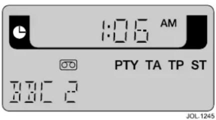
text_image
1:00 AM PTY TA TP ST JOL.1245Shown in AM/FM mode
On/Off and volume control
Press the control knob to switch the radio on, press again to switch off. Turn the control knob clockwise to increase or counter clockwise to decrease volume.
Any volume setting made whilst in audio, phone, or voice activation mode, will be memorised for that system.
Automatic Volume Control (AVC)
This maintains radio volume at a level sufficient to overcome road noise as vehicle speed increases or decreases. To activate AVC, press and hold the volume control knob until AVC is displayed. To deactivate AVC, momentarily press the volume control knob again. The level of AVC control can be adjusted by turning the volume control knob whilst in AVC ON mode. When AVC is ON, manual adjustment of volume will override the AVC setting.
MODE button

The MODE button functions at two levels. Mode level 1 is used to adjust sound performance. Mode level 2 can be used to adjust the audio display clock, to adjust Traffic Announcement (TA) and Voice Activation volume and to select Voice Activation Training. It can also inhibit the rear multimedia system controls.
Mode level 1
A short press and release of the MODE button will access the mode level 1 menu. Subsequent short presses of the MODE button will scroll through the available modes. When the desired mode is displayed, use the rotary volume control to adjust the setting.
Available modes
| BASS Increase/decrease | |
| TREBLE Increase/decrease | |
| BALANCE Left to right | |
| FADE Front to rear | |
| SUB LEVEL Premium audio only.Increase/decreasesubwoofers | |
| DSP POSITION | See detailed DSP text |
| ADVANCED MODE | Allows access to mode level 2. When ADV MODE N/Y is displayed,turn the rotary volume control to select ADV MODE YES.Subsequent short presses of the MODE button will scroll through the mode level 2 menu. |
Radio
Digital Signal Processing (DSP)
(Premium audio system only)
DSP can optimise sound performance for specific seating positions. To adjust the setting:
- In Mode level 1, scroll to DSP POSITION.
- Use the rotary volume control to cycle through POS F-LEFT (front left), POS F-RIGHT (front right), POS REAR and POS FRONT until the desired setting is achieved.
After approximately five seconds with no further actions or adjustments, the audio system will return to the previous display.
Note: To improve the comfort of passengers in the rear of the vehicle, the bass performance of the subwoofer is reduced when DSP mode is set to POS ALL or POS REAR.
For optimum bass performance, do not select POSS ALL or POS REAR
Mode level 2 - ADVANCED MODE
When ADV MODE YES is selected subsequent short presses of the MODE button will scroll through the available modes. When the desired mode is displayed, use the rotary volume control to adjust the setting.
Note: Mode level 2 can also be accessed via a long press of the MODE button.
Available modes
| CLOCK FORMAT SET | Select 12HR or 24 HR clock display. Press the MODE button to move to the next clock setting. |
| CLOCK HOUR SET | Adjust then press the MODE button to move to the next clock setting. |
| CLOCK MINUTE SET | Adjust then press the MODE button to save the clock settings and move to the next mode. |
| TA VOLUME Increase/decrease. | |
| VOICE VOLUME | Increase/decrease. |
| VOICE A Press the ‘seek up’ button to adjust. | |
| VOICE B Press the ‘seek up’ button to adjust. | |
Press and hold the MODE button to exit. The display will now revert to the screen in use before entering CLOCK SET.
Rear Seat Entertainment (RSE) controls
To inhibit the RSE controls, press and hold the MODE button until the current RMS MODE is displayed.
Radio
Rotate the volume control to select:
- RMS ON - This enables the RSE controls.
- RMS H/PHONE - The RSE control of the cabin speakers is inhibited. Control using headphones is still available.
- RMS OFF - This disables the RSE controls.
Change audio system source

Press the desired audio system source button.
Source tone memory
Bass and Treble positions are automatically memorised for AM radio, FM radio and CD, allowing individual settings for each mode.
BAND button
Pressing BAND repeatedly will cycle the radio through FM, Medium and Long wavebands (as applicable). Band selection will be shown in the display panel. When a CD is being played, pressing the band switch will select radio operation.
Presetting memorised radio stations


In the interests of road safety, do not attempt to preset a station while driving.
On each waveband, nine stations can be memorised using keypad buttons 1 to 9. After tuning to a station, press and hold the selected button until the unit 'beeps'. A station can be recalled from the preset memory by pressing and immediately releasing the button.
Pressing the steering wheel preset selector button will cycle through the preset stations.
Seek and manual tuning
In AM/FM mode, pressing and releasing the left or right button will activate the
radio in seek mode, tuning through the frequency range to the next available station. Pressing either button for more than two seconds will enter manual tuning mode.
Radio
Auto Memory (A MEM)

The automatic memory function programmes the nine strongest stations on a selected waveband to presets 1 to 9.
Note: These are additional to the preset stations described earlier.
To activate this function, press and hold A M E M button for at least two seconds.
The radio will be briefly muted while it searches the waveband for the nine strongest stations. When programming is complete the radio will default to preset number 1 and audio volume is restored.
If stations cannot be located for all preset positions, those that are found will be allocated positions commencing with number 1, leaving the remainder not programmed. The display will show NO FM or NO AM if a selected preset are is not programmed.
To switch between the A MEM preset stations and your own presets, press and immediately release the A M E M button.
A MEM with Radio Data System (RDS) selected
If the A M E M function is operated while in RDS mode, the radio will be muted briefly, while a search is made for the nine strongest RDS stations.
Radio Set Up
This function enables the radio to be set to user operating preferences. By selecting SET UP and using the preset buttons, the owner or Jaguar Dealer/Authorised Repairer can adjust certain radio functions.
When in SET UP, pressing the relevant preset button, as detailed below, will display the facility selected and its state. The state of that facility can be changed by pressing the preset button again.
To enter SET UP: Press CD Eject and AM/FM buttons simultaneously.
The display will show SET UP. The following preferences can be selected or changed in any order, within a 15 second period. After 15 seconds the display will clear and exit SET UP.
Preset 1
Press Preset 1 to enable or disable RDS availability in the user's country.
Preset 2 Blank
Preset 3 Blank.
Preset 4 Blank.
Preset 5 Blank
Preset 6 FM volume high (compensate for poor signal strength).
Note: This feature is not available in North America, Australia and Japan.
Preset 7 Blank.
Preset 8 Blank.
Preset 9 Blank.
Radio
Preset 10 During initial factory
installation, this is used to set the radio to one of the following regions: Europe, USA, Australia or Japan. Regional settings determine the correct frequency increments required for seeking stations, automatic tuning etc.
Note: The regions are preset at the factory. Should you require a regional change, consult your Jaguar Dealer/Authorised Repairer.
Radio
Press the control knob to switch the radio on, press again to switch off.
Pressing the AUDIO button can also turn on the radio. When using the touch-screen in other operating modes, such as Navigation, Television
(where fitted), Climate Control or any of the setup screens, pressing the AUDIO button will revert to the relevant audio screen.
Volume control

text_image
TAPE Volume DO 5 JOL 1627Turn the control knob clockwise to increase or counter-clockwise to decrease volume, across a range of settings (0 - 35) to be displayed during and momentarily after adjustment.
When using the rotary control knob to adjust volume the touch-screen will show the above display to assist setting. The pop-up volume control slide will disappear from the display after five seconds or can be removed by touching it.
Any volume setting made whilst in audio, telephone or navigation mode or JaguarVoice, will be memorised for that system.
Automatic Volume Control

text_image
VOLUME PRESET OK NAV AVG TA PHONE VOICEThis maintains radio volume at a level sufficient to overcome road noise as vehicle speed increases or decreases. To activate AVC, press the MENU button, followed by the VOLUME PRESET button on the touch-screen. Once in the volume preset screen, AVC level can be adjusted (from OFF to 5) by repeatedly pressing the + or - buttons adjacent to the AVC volume indicator.
When AVC is ON, manual adjustment of volume will override the AVC setting.
Volume preset adjustments
Volume for Telephone, JaguarVoice, TA and Navigation can also be adjusted by using the MENU button on the right of the screen and selecting the volume preset button as appropriate.
Radio
Audio setup

text_image
AUDIO SETUP Market EU JP US AUS RDS/RBDS On Off FM Volume High Low Key Off Eject On Off Tape Clean On OffThis function enables the radio to be set to user operating preferences. By selecting SETUP and using the buttons on the touch-screen, the owner or Jaguar Dealer/Authorised Repairer can adjust certain radio functions.
When in SETUP, pressing the relevant button will display the facility selected and its state. The state of that facility can be changed by pressing the button again.
To enter SETUP: Press Eject and AM/FM buttons simultaneously.
The display will show AUDIO SETUP. The preferences shown on the next page can then be selected or changed in any order. After 15 seconds the display will clear and exit SETUP.
Market During initial factory
installation, this is used to set the radio to one of the following regions: Europe, Australia or Japan. Regional settings determine the correct frequency increments required for seeking stations, automatic tuning etc.
Note: The regions are preset at the factory. Should you require a regional change, consult your Jaguar Dealer/Authorised Repairer.
RDS/RBDS Press ON/OFF buttons to enable or disable RDS, depending upon RDS availability in the user's country.
FM Volume FM volume high or low (compensate for poor signal strength).
Note: This feature is not available in Australia and Japan.
Radio
Digital Signal Processing (DSP)
DSP (premium audio system only) facilitates optimisation of sound for specific seating positions and is accessed via the DSP button shown on the touch-screen (audio screens only). The chosen setting can then be selected by touching the appropriate zone.
Options available are:
- Front left.
- Front right.
- Front centre.
- Rear seats.
- All seats.
Change audio system source

Press the desired audio system source button.
AM/FM mode
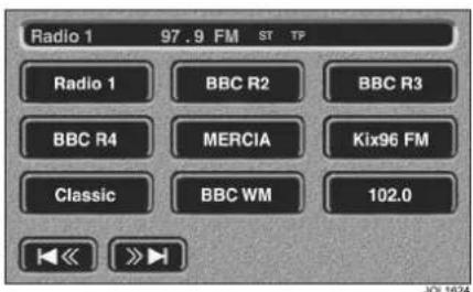
text_image
Radio 1 97.9 FM ST TP Radio 1 BBC R2 BBC R3 BBC R4 MERCIA Kix96 FM Classic BBC WM 102.0 << >> JOL1624In AM/FM mode, touch-screen buttons provide for station selection and retuning. In addition, the upper panel displays waveband, TA and PTY as selected using the buttons on the radio panel.
BAND
Pressing BAND repeatedly will cycle the radio through FM, MW, LW and DAB (as applicable). When a CD is being played, pressing the band button will select radio operation.
Presetting memorised radio stations

WARNING:
In the interests of road safety, do not attempt to preset a radio station while driving.
On each waveband, nine stations (18 each for FM and DAB) can be stored in the bank of nine buttons displayed on the touch-screen. To store a radio station as a preset, touch the selected button until a beep sounds to acknowledge the station has been stored.
A station can be recalled from the preset memory by momentarily pressing any of the preset buttons. The selected preset is highlighted by a red halo around the appropriate button.
Pressing the steering wheel preset selector button will cycle through the preset stations.
Seek and manual tuning

In AM/FM mode, touch and
release
activate the radio in seek
to
mode, tuning through the frequency range to the next available station. Pressing either button for more than two seconds will enter manual tuning mode.
Note: Manual tuning is not possible when using DAB.
Radio
Auto Memory (A MEM)

The automatic memory function programmes the nine strongest stations on a selected waveband to presets 1 to 9.
Note: Not available when using DAB.
Note: These are additional to the preset stations described earlier.
To activate this function, press and hold A M E M button for at least two seconds.
The radio will be briefly muted while it searches the waveband for the nine strongest stations. When programming is complete the radio will default to preset number 1 and audio volume is restored.
If stations cannot be located for all preset positions, those that are found will be allocated positions commencing with number 1, leaving the remainder not programmed. The display will show NO FM or NO AM as appropriate.
To switch between the A MEM preset stations and your own presets, press and immediately release the A M E M button.
A MEM with Radio Data System (RDS) selected
If the A M E M function is operated while in RDS mode, the radio will be muted briefly, while a search is made for the nine strongest RDS stations.
Digital audio broadcasting (DAB)
GENERAL INFORMATION
Digital radio reception

natural_image
Diagram of multiple concentric circular signal towers surrounding a road with a car (no text or symbols)E94094
DAB radio is very different from normal AM/FM radio in both operation and sound quality. The DAB network is designed to provide near CD quality from radio broadcasts. In most locations DAB signals are available without hiss, crackle, pop or interference, and no fading or overlap.
DAB radio can significantly increase the number of radio channels/stations available. The DAB signals are transmitted to most major cities, towns and motorway networks.
Radio signals travel in a straight line so large obstacles, such as tall buildings, can shield the vehicle from the signal, causing temporary loss of reception (known as dead spots).
Digital radio is transmitted from regional transmitters. Some local channels are not available outside the range of their transmitters. If you want to listen to local channels as you move around the country, use the auto-tune function TUNE to build new channel lists.
Ensembles
Unlike AM/FM radio, DAB transmits several stations/channels on a single frequency. A group of stations/channels is known as an ensemble. Ensembles may consist of six or more stations/channels (national or local). Some may have sub-channels offering several listening options.
Digital audio broadcasting (DAB)
If reception is lost when the vehicle is in motion No Reception will be displayed on the touch-screen.
The table below provides an example of the ensembles, channels and sub-channels available in one location.
| Ensemble Channel/ | Station Sub-Channel 1 Sub-Channel 2 | |
| First ensemble Channel/Station 1 | ||
| Channel/Station 2 Sub-Channel | ||
| Channel/Station 3 | ||
| Channel/Station 4 | ||
| Channel/Station 5 | ||
| Channel/Station 6 Sub-Channel Sub-Channel | ||
| Channel/Station 7 | ||
| Channel/Station 8 | ||
| Channel/Station 9 | ||
| Channel/Station 10 | ||
| Second ensemble Channel/Station 1 | ||
| Channel/Station 2 | ||
| Channel/Station 3 | ||
| Channel/Station 4 | ||
| Channel/Station 5 | ||
| Channel/Station 6 | ||
| Channel/Station 7 | ||
| Third ensemble Channel/Station 1 | ||
| Channel/Station 2 | ||
| Channel/Station 3 | ||
| Channel/Station 4 | ||
| Channel/Station 5 | ||
| Channel/Station 6 | ||
| Channel/Station 7 | ||
| Channel/Station 8 | ||
DAB Touch-screen
AUDIO CONTROLS
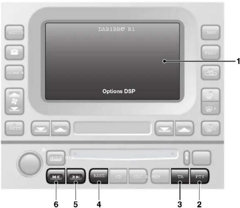
text_image
AUDIO DAB1BBQ R1 NAV MENU SLIMARK 1 Options DSP AUTO MODE 912 6 5 4 3 2JAG0842
- Touch-screen.
- PTY button.
- When PTY is selected programme information will be displayed.
- TA button.
- Press to enable or disable traffic announcements.
- BAND button.
- Press repeatedly to toggle through FM, MW/LW, DAB1, DAB2.
-
Seek up.
-
Short press to find the next channel.
-
Long press (two seconds) to find next available ensemble.
-
Seek down.
-
Short press to find previous channel.
- Long press (two seconds) to find previous available ensemble.
DAB Touch-screen
Steering wheel controls
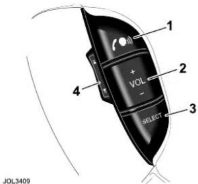
text_image
1 + VOL - 2 3 4 SELECT JOL3409- Start a voice command/Mute.
- Increase or decrease volume.
- Press the SELECT button repeatedly to scroll through the available audio sources FM, MW/LW, DAB1, DAB2, CD, iPod, USB, Auxiliary input and TV.
- Press repeatedly to scroll through DAB ensembles and stations/channels.
CHANNEL INFORMATION
Many digital channels transmit additional text (DLS, Dynamic Label Segment) to accompany a broadcast.
Additional information can be viewed by pressing Info repeatedly to scroll through the available information.
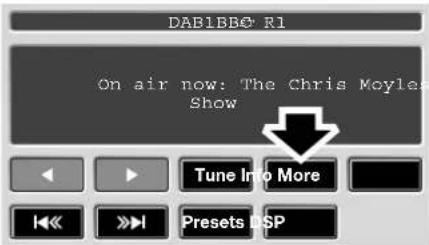
text_image
DAB1BB0 R1 On air now: The Chris Moyle Show Tune Into More Preset DSPJAG0855
Note: For safety reasons, this text does not scroll across the screen. Therefore some of the text may be truncated.
CHANNEL AUTOMATIC TUNING
When you first use the DAB radio, you will be unable to listen to any digital broadcasts. NO CHANNEL FOUND will be displayed until you have completed the auto-tune process.
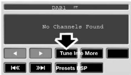
text_image
DAB1 5T No Channels Found Tune Into More Preset DSPJAG0843
Press TUNE to start automatic tuning and build a list of all the digital ensembles and channels that are available in your region.
While automatic tuning is running, the message DAB Auto-tune in progress will be displayed on the touch-screen. When tuning is complete, the first channel found will start playing.
Note: The auto-tune process may take longer than one minute to complete.
To update the list of local channels when you move to a different region, select TUNE again. You can also add local channels as presets to minimise the need for auto-tuning as you move location.
DAB Touch-screen
CHANNEL OPTIONS
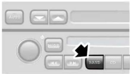
text_image
AUTO NOTE HSC BAND CDJAG0844
To receive digital broadcasts, short press the BAND button repeatedly to scroll through FM, MW/LW, DAB1, DAB2.
Choose DAB1 or DAB2 to receive digital radio broadcasts. The two DAB sources enable you to preset up to 18 different channels. PRESET BUTTONS, 283
The channel that was last played on your chosen digital source will be selected for playback automatically.
Note: If this is the first time you have used DAB radio, you must first build a list of available channels using the auto-tune function. CHANNEL AUTOMATIC TUNING, 280
Digital radio channels are organised into groups called ensembles. Some channels may sometimes provide one or more subchannels.

text_image
DAB1No®reception BBC R2 BBC R5LBBC R1 Virgin tlkSPORTPlantRock BBC R6M Audio BXFM Options DSPJAG0845
If the digital radio signal is lost or the system takes time to tune in to a channel, then the display screen will show the message No Reception. If the signal is lost whilst another system is in use, navigation for example, a pop-up will display the No Reception message.
Finding an ensemble
Long press (two seconds) the seek buttons to find the next or previous ensemble. AUDIO CONTROLS, 279
After a few seconds pause, the first channel in the ensemble found will start playing.
Finding a channel
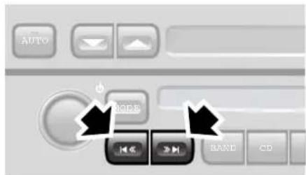
text_image
AUTO MODE BAND CDJAG0846
Short press one of the channel seek buttons to select the next available channel/station. The seek up button selects the next channel, the seek down button selects the previous channel.
Note: If the next or previous channel is in a different ensemble, then there will be a pause before the channel is located. The message Searching... is displayed on the screen.
On the touch-screen, if channels have been preset, select one of the six preset buttons to start playing that channel. If no channel has been preset, the button will display ---.
DAB Touch-screen
Finding a Subchannel

text_image
DAB1BBG-R1 On air now: The Chris Moyles Show Tune Info More I<< >>! Presets DSPJAG0862
If subchannels are available within a channel an asterisk will be displayed at the end of the channel name.
Short press one of the seek buttons to select the next available Subchannel. The seek up button selects the next channel, the seek down button selects the previous channel.
DAB SEARCH
Ensemble list
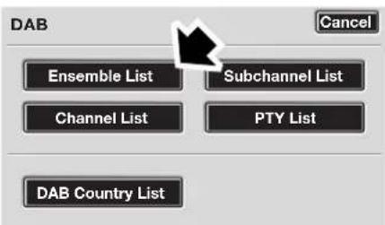
text_image
DAB Cancel Ensemble List Subchannel List Channel List PTY List DAB Country ListJAG0847
Select Ensemble List to display a list of all available ensembles. Select an ensemble name in the list to display a list of channels in that ensemble. Select a channel name to tune that channel.
Channel List

text_image
DAB Cancel Ensemble List Subchannel List Channel List PTY List DAB Country ListJAG0849
Select Channel List to display a complete list of all channels in all available ensembles. Select a channel name to tune that channel.
Subchannel List
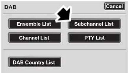
text_image
DAB Cancel Ensemble List Subchannel List Channel List PTY List DAB Country ListJAG0848
Select Subchannel List to display a list of any subchannels available for the currently tuned channel. If no subchannels are currently available, then the Subchannel List option is disabled. If the maximum five subchannels are available, then use the arrows to scroll through the list.
DAB Touch-screen
PTY
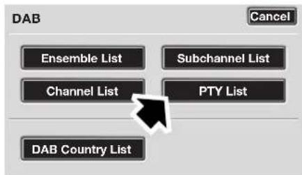
text_image
DAB Cancel Ensemble List Subchannel List Channel List PTY List DAB Country ListJAG0850
Channels are categorised by the broadcaster as belonging to a programme type (PTY) category. You can display a list of channels organised according to their PTY category.
Select PTY to display a list of PTY categories that contain channels. Select a PTY category to display a list of channels in that category. Select a channel name to play that channel.
Short press one of the seek buttons repeatedly during the first ten seconds of broadcast, to cycle through all channels contained in the PTY category that you chose.
PRESET BUTTONS
Storing channels as presets
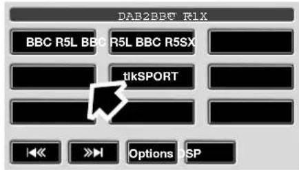
text_image
DAB2BBC R1X BBC R5L BBC R5L BBC R5SX tikSPORT Options DSPJAG0852
Store up to eighteen digital channels (nine each on DAB1 and DAB2) using the preset keys. Follow the procedure below to store channels as presets.
- Search for and start playing the channel you want to preset.
- Long press (two seconds) the preset button on which you want to store the current channel. Audio output is muted for a further two seconds while the channel is stored and a confirmation tone is heard.
- Repeat steps 1 and 2 for each channel that you want to store as a preset.
Note: You cannot store a subchannel as a preset. If you try to store a subchannel, you will store the channel to which the subchannel belongs.
Recalling a preset channel

text_image
DAB2tlkeSPORT BBC R5L BBC R5L BBC R5SX tlkSPORT Options SPJAG0853
Make sure that you have selected the appropriate digital source (DAB1 or DAB2) and then short press the preset button you require. The channel you have selected will start to play automatically.
Note: If you try to recall a channel that has previously been stored as a preset but is now unavailable or invalid, the message No channel found is displayed. You must choose another channel.
DAB Touch-screen
SETTINGS
Traffic Announcements
You can select Traffic Announcements when listening to DAB.
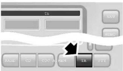
text_image
TA DAY MONTH BAND CD CDC A MEM TA FTYJAG0854
When a DAB traffic announcement is broadcast, it will interrupt normal play for the duration of the announcement.
Note: If traffic announcement (TA) has been selected whilst listening to an FM station, it will de-select when DAB is selected using the band button. To continue TA coverage during DAB broadcasts press the TA button with DAB selected.
DAB country
If you move the vehicle to a different country, you can change DAB Country option to make sure that you receive the best possible reception and sound quality.
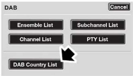
text_image
DAB Cancel Ensemble List Subchannel List Channel List PTY List DAB Country ListJAG0851
Select DAB Country to display a list of countries where DAB services are available. Select the country name to enable it.

text_image
DAB COUNTRY / BAND LIST ANDORRA AUSTRALIA AUSTRIA BELGIUM BOSNIA CancelJAG0860
Note: When you change the DAB country, the audio unit will automatically start auto-tuning. If you Cancel the auto-tune, the country setting will remain changed but you may not have access to all available ensembles for that country.CHANNEL AUTOMATIC TUNING, 280
Note: For safety reasons this option is disabled when the vehicle is moving.
DAB Touch-screen
DAB format

text_image
DAB COUNTRY / BAND LIST BAND 3 BAND L BAND 3L BAND L CAN BAND 3L CAN CancelJAG0861
Different regions or countries may use different digital bands to broadcast DAB channels. If you know the band(s) required then you can choose from the
Band selection list.
Select Change to display a list of formats. The available bands are:
- LBand
- BandIII
• LBand & BandIII - LBandCanada
• LBandCan & BandIII
Note: When you change the DAB format, the audio unit will automatically start auto-tuning. If you cancel the auto-tune, the new format setting will remain, but you may not have access to all available ensembles for that format.
Note: For safety reasons this option is disabled when the vehicle is moving.
Single CD Player
SINGLE CD PLAYER - STANDARD AUDIO
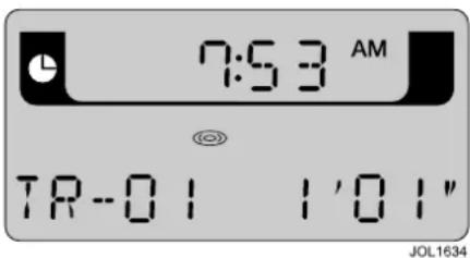
text_image
7:53 AM TR-01 1'01" JOL1634The audio display will indicate which function has been selected. Messages include; LOADING, EJECTING, MIX TRACKS, REPEAT TRACK, PAUSED and CUE/REVIEW.
Inserting a CD into the CD aperture will start immediate play. The display will show LOADING, followed by TR-01 00' 00". The CD symbol will also be displayed until the CD is ejected, regardless of the selected audio source.
Eject and CD-in indicator

When a CD is inserted, the CD icon is displayed. Press to eject the CD. The display will show DISC EJECT and the CD icon will be turned off.
MIX

To play random tracks from the disc, press and release the MIX button. MIX will be displayed. To cancel, press the MIX button again.
CD button

If you are playing the radio or CD changer, pressing the CD button will resume playing any CD installed in the player mechanism.
The audio display will show
TR-NN MM' SS", where NN is the current track number and MM SS is the track time in minutes and seconds.
Pressing the CD button while in CD play mode will pause the current track, the display will show TR-NN PAUSE where NN is the current track number. A subsequent press of the CD button will resume play mode.
This function can also be controlled by a switch on the steering wheel.
REPEAT

Press and release REPEAT button to repeat the current CD track being played. To cancel, press the REPEAT button again.
Seek up and down

This control selects seeking of tracks up or down. Momentarily press the
right-hand button to skip to the next track. Repeated pressing will select further tracks.
The left-hand button returns to the beginning of the current track. Repeated pressing selects previous tracks.
Pushing and holding either button selects cue and review of the CD.
Note: Sound level is reduced when cueing and reviewing a CD.
Single CD Player
SINGLE CD PLAYER WITH TOUCH-SCREEN
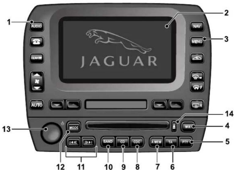
text_image
1 AUDIO JAGUAR 2 NAV 3 MENU 4 F AUTO 5 MODE 6 MIX 7 8 9 10 11 12 13 14JAG0864
- AUDIO. Press to turn audio system ON, or to display relevant audio screen and associated touch-screen buttons.
- Touch-screen display.
- MENU. Press to access touch-screen options.
- MIX. Mix CDs or CD tracks playing order.
- PTY. Priority Programme Type (where broadcast).
- TA. Traffic Announcement and Radio Data System (where broadcast).
- A MEM. Automatically set station presets.
-
CDC. Select CD changer.
-
CD. Select compact disc play when in other audio mode, or CD pause (when a CD is inserted and playing).
- BAND. Radio waveband select.
- Seek AM/FM station, cue/review CD.
- MODE. Scroll to select sound settings.
- ON/OFF and volume control.
- Eject CD.
Single CD Player
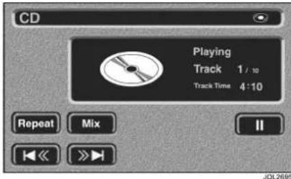
text_image
CD Playing Track 1 / 10 Track Time 4:10 Repeat Mix II JOL2695In CD mode, touch-screen buttons (shown above) provide selection of CD tracks.
The display will show the CD screen. The CD symbol will be displayed until the CD is ejected, regardless of the selected audio source.
Inserting a CD into the aperture will start it playing.
Eject

Press to eject the CD.
Mix

To play random tracks from the disc, press and release the Mix button. MIX will be displayed. To cancel, press the Mix button again.
Repeat

Press and release Repeat button to repeat the current CD track being played. To cancel, press the Repeat button again.
Pause

Touch the pause button to pause CD play.
Note: Pause button function changes to a play button, a subsequent press will resume CD play.
CD button

If you are playing the radio or CD changer, pressing CD will play the CD in the player. This function can
also be controlled from the appropriate button on the steering wheel (see page 262).
Seek up and down

Touch and release to seek tracks up or down.
Momentarily press the
right-hand button to skip to the next track. Repeated pressing will select further tracks.
The left-hand button returns to the beginning of the current track. Repeated pressing selects previous tracks.
Pushing and holding either button selects cue and review of the CD.
Note: Sound level is reduced when cueing and reviewing a CD.
Compact Disc Changer
COMPACT DISC (CD) CHANGER OPERATION
A CD changer (where fitted) is installed in the luggage compartment and will accommodate up to six discs, each mounted in a tray.
Caution: The 8 cm diameter discs and associated adaptors available in some countries must not be installed in the CD changer magazine. Any attempt to install these items can result in permanent damage to the CD changer mechanism.
CD check sequence
When the CD Player is switched on, a check is performed on each disc tray in the CD changer magazine. When the six trays have been checked the player returns to the first disc in the magazine.
Loading discs and inserting magazine Loading a disc into a magazine tray:
Slide the magazine door to the right (1). Press the eject button (2), the magazine will then partly eject from the CD changer. Pull the disc tray from the magazine (3). Ensuring the playing surface is not touched, load a selected disc into the tray with the label facing upwards (4). Push the tray back into the magazine until it clicks. Tray slots are numbered 1 (bottom) to 6 (top).
Inserting the magazine: With the arrow mark facing upwards and pointing towards the CD changer, insert the loaded magazine into the CD changer (5) ensuring that it clicks into position. Close the sliding door. Keep the sliding door closed to prevent dust entering the playing mechanism.

text_image
1 JAGUAR 2 3 4 5 JOL3299Compact Disc Changer
CD CHANGER - STANDARD AUDIO
CD changer mode
The audio display indicates the CD and track being played, and CD status.
Below is an example of the display when playing track 1 from CD4.
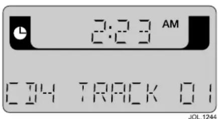
text_image
2:23 AM C14 TRACK 01 JOL.1244Other messages:
CD1 LOADING CD1 is being loaded.
NO DISC In the selected position.
NO MAGAZINE In the CD autochanger.
CD1 MIX 10 The player is playing CD1 in MIX mode (track 10).
DMIX All CDs are in MIX mode.
MAG EJECT Magazine is being ejected.
PAUSED The CD changer is paused and ready to play.
CDC button

Press CDC to select CD changer mode.
This function can also be controlled from the appropriate switch on the steering wheel.
CD selection

Preset buttons 1 to 6 select the compact discs in those positions in the magazine. If there is no disc in the selected position, NO DISC will be displayed. If there is no magazine in the CD changer, NO MAGAZINE will be displayed.
MIX

To play random tracks from the disc, press and release the MIX button. MIX will be displayed. To cancel, press the MIX button again.
To play random tracks from all discs present in the magazine, press the MIX button for two seconds. DISC MIX will be momentarily displayed, followed by D MIX. To cancel, press and hold the MIX button.
Seek up and down

This control selects seeking of tracks up or down. Momentarily press the
right-hand button to skip to the next track. Repeated pressing will select further tracks.
The left-hand button returns to the beginning of the current track. Repeated pressing selects previous tracks.
Pushing and holding either button selects cue and review of the CD.
Compact Disc Changer
Note: Sound level is reduced when cueing and reviewing a CD.
REPEAT

Momentarily press the REPEAT button to repeat the current CD track being played,
R-ONE will be displayed. To cancel, momentarily press the REPEAT button again.
Press and hold the REPEAT button for two seconds to repeat the current CD, R-ALL will be displayed. To cancel, press and hold the REPEAT button again for two seconds.
Pause

When playing a CD, press CDC button to pause play. Press again to continue play.
CD CHANGER WITH TOUCH- SCREEN
CD changer mode
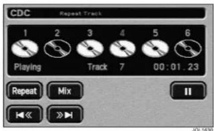
text_image
CDC Repeat Track 1 2 3 4 5 6 Playing Track 7 00:01.23 Repeat Mix II JOL1630In CD changer mode, touch-screen buttons (shown above) provide for track and disc selection. Discs present in the magazine are highlighted in the display.
A disc is selected by touching the appropriate disc button which, when playing, has a red active surround.
The track and track duration are displayed during play.
CDC button

Press CDC to select CD changer mode.
Note: This function can also be controlled from the appropriate button on the steering wheel (see page 262).
Mix and CD mix

To play random tracks from a selected disc, press and release the Mix button. MIX TRACKS
will be displayed. To cancel, touch the Mix button again.
Compact Disc Changer
To play random tracks from all discs present in the magazine, touch and hold the Mix button for more than two seconds. MIX ALL will be displayed. To cancel, touch and hold the Mix button.
Seek up and down

Touch and release to seek tracks up or down.
Momentarily press the
right-hand button to skip to the next track. Repeated pressing will select further tracks.
The left-hand button returns to the beginning of the current track. Repeated pressing selects previous tracks.
Pushing and holding either button selects cue and review of the CD.
Note: Sound level is reduced when cueing and reviewing a CD.
Repeat

Momentarily press the Repeat button to repeat the current CD track being played. REPEAT
TRACK will be displayed. To cancel, momentarily press the Repeat button again.
Press and hold the Repeat button for two seconds to repeat the current CD.
REPEAT DISC will be displayed. To cancel, press and hold the Repeat button again for two seconds.
Pause

Touch the pause button to pause CD play.
Note: Pause button function changes to a play button, a subsequent press will resume CD play.
TV General Information
INTRODUCTION
The TV tuner in the Switch and Display Unit provides TV viewing when the vehicle is stationary.
The TV picture is inhibited automatically when the vehicle is in motion.
With the TV function selected, but the picture inhibited, the TV sound continues to be available.
TV sound is provided through the audio system speakers.
Note: Television systems require consistent and strong signals for good quality reception. These signals are affected by transmitter coverage and surrounding features (hills, high buildings, trees etc.) which will reduce the signal, thus reducing picture quality.
Repositioning the vehicle may improve the picture whereas in difficult locations (distant transmitter, hills etc.) reception may not be possible at all. Sound quality may also be affected to a lesser degree by the above, which can give rise to variable quality over short distances while on the move.
TV inhibit with vehicle moving
If the vehicle is moved whilst the TV picture is being displayed, the TV will be inhibited and returned to the TV Menu screen.
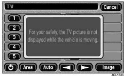
text_image
For your safety, the TV picture is not displayed while the vehicle is moving.A warning indicator will appear across the screen for three seconds stating 'For your safety, the TV picture is not displayed while the vehicle is moving'.
Special features overview
- Change screen mode:
Three different screen modes are available, normal, wide 1 or wide 2. - Change country of operation:
This feature allows the TV to be tuned to the channels available when driving in another country.
• Full teletext functions:
All normal functions of the teletext system are available, subject to local TV station transmissions.
• Telephone end call function:
A telephone call may be ended (whilst TV is on) by selecting an icon on the TV screen.
JaguarVoice operation of TV
The TV system can be operated with JaguarVoice. Please refer to the Voice Control chapter of this handbook (starting on page 323).
TV Basic Controls
SWITCHING ON THE TV
The following instructions assume that the appropriate country of operation has been selected and the tuning presets have been set. Where this is not the case, refer to the relevant section.
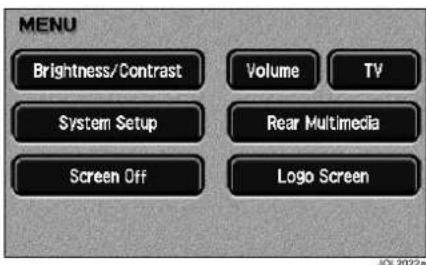
text_image
MENU Brightness/Contrast Volume TV System Setup Rear Multimedia Screen Off Logo Screen JOL 2022aPress the MENU button located on the right-hand side of the Switch and Display Unit. The System Menu will be displayed (shown above). The layout of this menu changes if the rear multimedia system is fitted: refer to the rear multimedia handbook
At the System Menu, select TV to display the TV Menu screen.
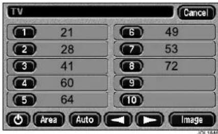
text_image
TV 1 21 6 49 2 28 7 53 3 41 8 72 4 60 9 5 64 10 Area Auto ImageOn the TV Menu screen select either, one of the presets (marked 1 to 10) or the Image button.
Note: If a preset has no channel number shown, then it cannot be selected to display a TV picture.

natural_image
Black-and-white landscape photo showing a coastal view with trees, a wooden railing, and distant buildings (no visible text or symbols)The TV picture will be displayed. TV screen shown in Wide Mode 1.
TV Basic Controls
Switch off the TV and return to system menu screen
Touching the TV screen at any time will return to the TV Setup display.

text_image
Black-and-white photo of a coastal scene with trees, buildings, and UI icons including play button, navigation menu, and TV directory.On the TV Setup display, touch the TV Menu icon to show the TV Menu screen.
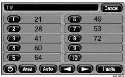
text_image
TV 1 21 6 49 2 28 7 53 3 41 8 72 4 60 9 5 64 10 Area Auto Image JOL1846To return to the System Menu screen, select Cancel at the top right-hand corner of the TV Menu screen.
Switch off the TV and set all systems to be dormant
Touch the TV screen to revert to the TV Setup display.
On the TV Setup display, touch the TV Menu icon to show the menu screen.
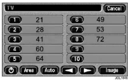
text_image
TV Cancel 1 21 6 49 2 28 7 53 3 41 8 72 4 60 9 5 64 10 Area Auto Image JOL1646Touch the On/Off button at the bottom left of the TV Menu screen.
The screen will go off, the TV sound will go off and either the previously selected audio system will play, or the system will remain quiet if previously no audio system had been selected.
Selecting a preset channel
To change to another preset channel while viewing the TV, touch the TV screen to return to the TV Setup display.
Select the TV Menu icon to show the TV Menu screen.
On the TV Menu screen, select the desired channel preset, marked 1 to 10.
The selected TV channel will be displayed.
Setting the volume
The TV volume is controlled from the vehicle audio system
TV Basic Controls
Icons used in basic controls
Use of the following icons is described in this section:

Selects the TV MENU screen.

Selects the TV Adjust display.

Selects contrast adjustment.

Selects brightness adjustment.

Selects colour adjustment.

Returns to TV screen.
Adjusting contrast, brightness or colour
To adjust the TV contrast, brightness or colour, touch the TV screen to return to the TV Setup display.
Touch the TV Adjust icon to show the adjustment screen. This screen is displayed in Wide 1 mode.
After approximately eight seconds, if no icon has been selected, the TV Adjust screen will change to the normal TV screen.

flowchart
graph TD
    A["User"] --> B{Access}
    B -->|Yes| C["Connect"]
    B -->|No| D["Send"]
    C --> E["User"]
    D --> F["Connection"]
    style A fill:#f9f,stroke:#333
    style E fill:#ccf,stroke:#333
    style F fill:#cfc,stroke:#333
JOL 1193
Touch the adjustment slider icon adjacent to the required symbol, contrast, brightness or colour, at either end of the slider to adjust for more or less.
When adjustments are complete, touch the Return icon to return to the TV screen.
Note: Changes made to the TV Adjust menu only alter the appearance of the TV image. Refer to page 258 for details of how to adjust the brightness and contrast of the touch-screen in all other modes.
TV Tuning
TUNING
The following instructions describe the various methods available for tuning the TV.
Not every screen view which is mentioned in this TV Tuning section is shown. If necessary, refer to the TV Basic Controls section (starting on page 294) for those screen views which are not shown.
The touch-screen system audible feedback must be set to ON in order to provide the double beep when tuning. If necessary, this can be set as follows:
-
Press the MENU button located on the right-hand side of the Switch and Display Unit. The System Menu will be displayed. See SWITCHING ON THE TV, page 294.
-
Select System Setup, User Settings and set Audible Feedback to All, Touch Screen or None.
Icons used in tuning
Use of the following icons is described in this section:

Selects the TV MENU screen.

Tune up/Seek up. Touch and release increases channel number by one. Touch and hold for between two and three seconds, seeks the next strongest channel and stops.

Tune down/Seek down. Touch and release decreases channel number by one. Touch and hold for between two and three seconds, seeks the next strongest channel and stops.

Cycle up through preset channels.

Cycle down through preset channels
TV Tuning
Setting channel presets using the auto function
Touch the TV screen to return to the TV Setup display.
Select the TV Menu screen.

text_image
TV 1 21 2 28 3 41 4 60 5 64 6 49 7 53 8 72 9 10 Area Auto ImageOn the TV Menu screen, touch and hold the Auto button for between two and three seconds until a double beep sounds.
The Auto and Tune/Seek buttons will become disabled, and the channel number will start to increase.
The ten strongest channels (if ten are available) will be stored on the channel selection preset buttons (the strongest channel on preset 1, the weakest on preset 10).
When finished, the Auto and Tune/Seek buttons will be enabled and preset 1 will be selected automatically.
Setting channel presets manually
Channels may be manually scanned from either the TV Menu screen or the TV Setup display.
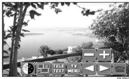
text_image
Black-and-white photo of a coastal scene with trees, buildings, and UI icons including play button, navigation icon, and TV menu.Touch and hold the appropriate Tune/Seek icon (Left or Right facing arrow) for between two and three seconds until a double beep sounds.
The icon will be disabled whilst seeking a channel and audio output will be muted.
When a channel is found and the seek procedure stops, TV sound will be heard and the channel number at the top of the screen will be static.
Either, repeat the seek procedure until the desired channel has been found or store the channel in a preset.
TV Tuning
Using the TV Menu screen for tuning.
The TV picture is not visible.
This new channel can now be stored in any preset by touching and holding the preset until a double beep is sounded.
To view the new channel before storing it in a preset, touch the IMAGE button to display the TV screen.
If storing the channel, touch the TV screen to return to the TV Setup display. Touch the TV MENU icon. At the TV menu screen, store the channel in any preset by touching and holding the preset until a double beep is sounded.
Using the TV Setup display for tuning.
The TV picture is visible.
The TV Setup display may have defaulted to the normal TV screen. If storing the channel, touch the TV screen to return to the TV Setup display.
Touch the TV MENU icon. At the TV menu screen, store the channel in any preset by touching and holding the preset until a double beep is sounded.
Changing a preset to a different stored channel
As an example, if the channel on preset 8 needed to be copied to preset 5:
On the TV Menu screen, select preset 8.
Whilst the channel on preset 8 is active (TV picture and sound is on) touch the screen to show the TV Setup display, then select the TV Menu icon.
On the TV Menu screen, touch and hold preset 5 until a double beep is sounded.
The channel that was previously on preset 8 is now on preset 5 and still on preset 8. The channel that was on preset 5 is lost.
Manual tuning
Touch the TV screen to show the TV Setup display. The TV Menu screen can also be used, but the TV picture is not available.
Touch the appropriate Tune/Seek icon (Tune up/Seek up or Tune down/Seek down) for approximately one second. Each time one of the icons is touched, the channel number increases or decreases by one.
Repeat the procedure until the desired channel has been found. The new channel may be viewed at this point and lost when the TV is switched off, or stored in a preset for future selection.
TV Tuning
TO SET COUNTRY OF OPERATION
Not every screen view which is mentioned in this section is shown. If necessary, refer to the TV Basic Controls section (starting on page 294) for those screen views which are not shown.
The TV can easily be set to operate in a number of countries.
To set or change the country of operation, display the TV Menu screen:
- From the System Menu screen of the Switch and Display Unit, select TV to display the TV Menu screen, or;
- From the TV Setup display, select the TV MENU.
Select Area to display the Country Selection Screen.
Note: The TV system will only receive UHF frequencies, not VHF frequencies.
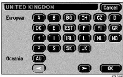
text_image
UNITED KINGDOM European A B BG CH CZ D OK E EST F FI GR H I IRL L NL NO P S SK UK Oceania AU OK JOL2497If Area is selected, the country selection buttons are shown, with the currently selected country button highlighted.
Choosing a different selection button for another country will highlight the selected button.
To accept the new setting, select OK. To reject the new setting, select Cancel.
There are two screens for country selection and the arrows at the bottom change from one screen to the next.
Note: If your country is not displayed then selection of one of the P or S prefixed buttons should enable you to receive a picture. P and S refer to PAL and SECAM TV in different countries.
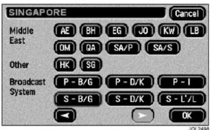
text_image
SINGAPORE Cancel Middle East AE BH EG JO KW LB OM QA SA/P SA/S Other HK SG Broadcast System P - B/G P - D/K P - I S - B/G S - D/K S - L'/L OK JOL2498If the new setting is accepted, a warning message will be displayed to indicate that the selection of a different area will erase the current preset channels. The final choice to accept or reject the new setting is offered.
Choosing Yes returns to the TV Menu with the new area selected, but with no preset channels; selecting No returns to the Country Selection Screen.
TV Tuning
CHANGE SCREEN MODE
Not every screen view which is mentioned in this section is shown. If necessary, refer to the TV Basic Controls section (starting on page 294) for those screen views which are not shown.
Icons which are used in this section are listed at the end of this section.
There are three different display modes for the television, Normal, Wide 1 and Wide 2.
Normal Mode – standard television 4:3 format. A black strip is displayed to each side of the picture.
Wide 1 Mode – increases the viewing area of Normal Mode to the full size of the screen.
Wide 2 Mode – TV picture is displayed in 4:3 format, but to fit the screen horizontally. Used to display pictures broadcast in Wide Screen format.
Touch the TV screen to return to the TV Setup display. Touch the Mode icon (icon with two TV screens) to show the Mode Change screen.
Touch the appropriate icon for the desired display mode and touch the Return icon to return to the TV.
If no action is taken on the screen, a return to TV in the original mode will occur after approximately eight seconds.
Icons used in change screen mode
Use of the following icons has been described in this section:

Selects the TV Mode Change screen. This icon is on the TV Setup display.
Selects Normal 4:3 mode.

Selects Wide 1 mode.

Selects Wide 2 mode.

Returns to TV screen.
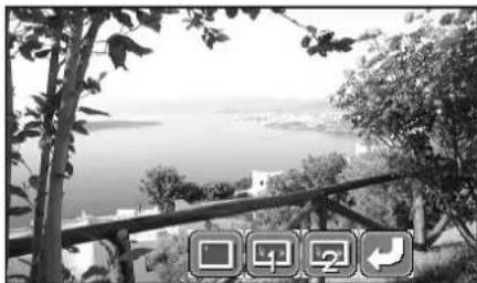
natural_image
Black-and-white landscape photo showing a coastal view with trees, a railing, and distant buildings (no visible text or symbols)JOL.1201
Only two screen icons will ever be displayed (not as shown above, which is for explanation only) on this Mode Change screen because the currently selected mode can not be selected.
Teletext
INTRODUCTION
Not every screen view which is mentioned in this section is shown. If necessary, refer to the TV Basic Controls section (starting on page 294) for those screen views which are not shown.
Icons which are used in this section are listed at the end of this section.
Select teletext
With the desired TV channel selected, touch the screen to select the TV Setup display.
Select the TELETEXT icon.
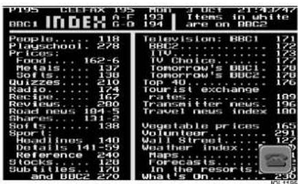
text_image
PTPS CEFAX 195 Mon J OCT 21/4/247 BBC1 INDEX A-F 193 Items in white are on BBC2 People... 118 Television: BBC1 171 Playschool... 278 BBC2 ... 172 Prices: 110 ... 173 Food... 162-6 TV Choice: 177 Metals... 137 Tomorrow's BBC1 178 Soil... 140 Tomorrow's BBC2 179 Quizzes... 210 Top 40 ... 176 Radio... 174 Tourist exchange Recipe... 167 rates ... 189 Reviews... 280 Transmitter news. 196 Road News... 104-5 Travel news index 180 Shares... 131-2 Softs... 138 Vegetable prices 165 Sport: Volunteer ... 291 Headlines... 140 Wall Street ... 127 Days... 141-5 Weather index ... 9 Reference... 240 Maps ... 1 Stocks... 128 Forecasts ... 1 Subtitles... 170 In the resort ... 5 and BBC2 ... 270 What's On ... 230The normal teletext screen (Text Screen 1) shown above will be displayed. Each text screen is displayed in Wide 1 mode.

text_image
PDS: CEFAX 195 Mon J Oct 21-14 INDEX A-F 193 Items in G-D 194 are on BBC e. 118 school 278 162-6 137 138 210 174 167 160 184-5 131-2 138 Headlines 140 Det 141 Ket e 2 Stock Subt and BBC 270 Television: BBC BBC2 TV Choice Tomorrow's BBC Tomorrow's BBC Tourist exchange Rates Transmitter news Travel news Inds Vegetable prices Volunteer... Wall Street... 127 Wet in... 29 He'sis... In res... What's On... 230 TVTouch the normal teletext screen (Text Screen 1) to display a second text screen (Text Screen 2), containing icons.
If an icon is not selected within eight seconds, the screen will revert to the normal teletext page (Text Screen 1).
Selecting a teletext page
On Text Screen 2, shown in the previous illustration, select the numeric keypad icon, which is at the top left-hand corner of the screen.
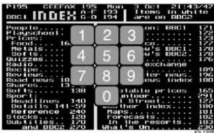
text_image
PI95 CECEFAX 195 Mon 3 Oct 21:43/47 A-F 193 Items in white BCC1 INDEX G-0 194 are on BCC2 People... 1 2 3 on: BBC1 121 Playschool... 1 2 3 172 Prices: ... 173 Food... 16 ice... 177 Retals... 4 5 6 w's BBC1 178 Soils... 4 w's BBC2 178 Quizzes... 176 Radio... exchange Recipe... 7 8 9 enter news 189 Refies... 16 soad news 19 eus index 196 Shares... 13 Softs... 138 0 stable prices 165 Spot... 291 Routines... 140 Street... 128 Details... 141-59 other Index 180 Reference... 240 Maps... 181 Stocks... 128 Forecasts... 182 Subtitles... 170 In the resorts. 183 and BBC2 279 What's On... 100/1205With the numeric keypad displayed, select the desired three-digit teletext page number. The page will be selected and displayed in Text Screen 1.
If a key is not touched within three seconds, the screen reverts to the previous screen (Text Screen 2). Alternatively, touch the screen anywhere except the keypad, to return to Text Screen 2.
Return to TV
Touch Text Screen 1, the default text screen, to display Text Screen 2.
Touch the TV icon.
Teletext
Icons used in teletext mode

Select teletext. This icon is on the TV Setup display.

Increase the page number.

Decrease the page number.

Hold the page displayed or release the currently held page.

Display hidden text e.g. answers to a quiz.

Choose the Numeric Keypad. Used to input the desired text page.

Mix TV and Text. Each touch of the icon steps through the sequence, Teletext, TV, Mixed (TV and Teletext superimposed), Teletext.

Large Text. Each touch of the icon steps through the sequence, Normal size, Upper half of the screen expanded, Lower half of the screen expanded, Normal size.

Fast Text. There are four fast text icons, red, green, yellow and blue. Each colour of icon corresponds to the same coloured link displayed at the bottom of the displayed page. Return to TV.

Telephone Introduction
INTRODUCTION
What is Bluetooth?
Bluetooth is an international standard that allows electronic components to communicate with each other, using a short-range radio link. Bluetooth eliminates the need for wires or cables: typically, devices can communicate at a range of up to 10 metres (33 feet).
The Bluetooth in-car telephone system allows certain mobile phones to be used hands-free in your vehicle: there is no need to connect the mobile phone to a cradle or cable.
Bluetooth is a registered trademark of Bluetooth SIG, Inc.
SYSTEM OVERVIEW
The vehicle's Bluetooth telephone system can be used with an appropriate, Bluetooth-equipped mobile phone.
The mobile phone must be paired with the vehicle system before use. See page 308 for more information.
Once paired, the mobile phone can be operated via the steering wheel switches or the keypad and phone buttons on the audio panel or touch-screen. The mobile phone doesn't need to be physically connected to the vehicle: it can be left in a jacket pocket, for instance. Calls are routed through the vehicle's audio speakers, and a dedicated microphone is fitted to the roof lining, near the driver's head.
You can use the system to answer or reject incoming calls, make outgoing calls or alter the call volume. The system does not support SMS text messages.
Note: The vehicle ignition must be set to position I or II in order to use the phone.
Call volume
The volume of telephone calls can be adjusted for hands-free phone operation. To adjust the volume, operate the audio system's ON/OFF volume control during a phone call.
If the audio system is in use when the phone becomes active, the audio system source is suppressed for the duration of the call.
The Jaguar telephone system is designed to function with a wide variety of Bluetooth-equipped mobile phones. The audio and echo characteristics vary between models of mobile phones: as a result, it may take a few seconds for the vehicle system to adapt to provide optimal audio performance.
In order to achieve the best possible audio performance, it may be necessary to reduce the system volume slightly when using certain mobile phones.
Audio panel display
Phone related messages are shown on the audio panel display or touch-screen (where fitted) when the phone system is active.
Telephone Introduction
VOICE ACTIVATION
(Where fitted)
The Bluetooth telephone system can be used in conjunction with the voice activation system to provide the driver with completely hands-free communication. Voice commands are picked up by the system microphone.
For information about using voice activation, refer to the Voice Control section, starting on page 323.

WARNING:
The voice activation system must not be used to call emergency numbers, as voice patterns can change under stress, resulting in commands becoming unrecognisable.
SAFETY

WARNING:
Read this information before using your in-car telephone system.
Driving
Check local regulations on the use of telephones in the areas where you drive and always obey them. Observe the following guidelines when using your phone whilst driving:
- Give full attention to driving - safe driving is your first responsibility.
• Always use hands-free operation when driving. - When receiving a call, if driving conditions demand, pull off the road and park.
Electronic devices
Most modern electronic equipment is shielded from radio Frequency (RF) signals.
However, certain equipment may not be shielded against RF signals from your telephone.
Pacemakers
The Health Industry Manufacturers Association recommends that a minimum separation of 15 centimetres (6 inches) is maintained between a wireless phone antenna and a pacemaker to avoid potential interference with the pacemaker. These recommendations are consistent with the independent research by and recommendations of Wireless Technology Research.
Telephone Introduction
Persons with pacemakers should:
- Preferably use the vehicle hands-free system.
- ALWAYS keep the phone more than 15 centimetres (6 inches) from their pacemaker when the phone is switched ON.
- Turn the phone OFF immediately if there is any reason to suspect that interference is taking place.
Other medical devices
If you use any other personal medical device, consult the manufacturer of your device, or your doctor, to determine that it is adequately shielded from external RF energy.
Turn your phone OFF in health care facilities when any regulations posted in such areas instruct you to do so. Hospitals or health care facilities may be using equipment that could be sensitive to external RF energy.
Vehicles
RF signals may affect non-Jaguar or improperly installed equipment. Always consult the manufacturer of any equipment that has been retro-fitted to your vehicle.
Posted facilities
Turn your phone OFF in any facility where posted notices so require.
Blasting areas
To avoid interfering with blasting operations, turn your phone OFF when in a blasting area or in areas posted: Turn off two-way radios. Obey all signs and instructions.
Potentially explosive atmospheres
Areas with a potentially explosive atmosphere are often, but not always, clearly marked. Turn your phone OFF when you are in such an area, as the use of unapproved electrical equipment can cause an explosion or fire resulting in bodily injury or death.
Airbags
Airbags inflate with great force.

WARNING:
Do NOT place objects, including both installed or portable wireless equipment, in the area over an airbag or in the airbag deployment area. If in-vehicle wireless equipment is improperly installed and the airbag inflates, serious injury could result.
Telephone System
STEERING WHEEL CONTROLS
Four system control switches are situated on the left-hand side of the steering wheel, duplicating the functions of buttons on the audio panel. These switches provide finger-tip control of audio, telephone and voice activation systems whilst driving.

text_image
1 + VOL - 2 3 4 JAG0655| Switch Function | |
| 1 Start voice function, or mute where voice not fitted. Answer phone call when ringing. Send/End when in Phone mode. | |
| 2 Increase/decrease volume. | |
| 3 Hold for two seconds to select Phone Ready mode. Press and release to cycle through FM, AM, CD and CD Changer. | |
| 4 In Phone mode, scroll through stored numbers. In Audio mode, scroll through radio stations or CD tracks. Press and hold to select next strong radio station or next CD. |
Note: Switches 2 and 4 are rocker switches.
Telephone System
PAIRING YOUR PHONE
Before use, your mobile phone must be connected or paired with the vehicle's Bluetooth system.
Vehicles with touch-screen
Follow these steps to pair your phone with the vehicle:
- Switch the vehicle's ignition ON (position II).
- Press the button, to the left of the touch-screen.
- Ensure that no phone is currently connected to the car.
- The message Discover Me will be displayed, to confirm that the system is ready to pair with a mobile phone.
- Switch on your mobile phone's Bluetooth connection, using the phone's menu. (See your phone's manual for more information).
- Select search for other Bluetooth devices or Audio Accessories from your mobile phone's menu.
- Select Jaguar in your phone's paired device list, in order to connect to the vehicle's Bluetooth system.
- Enter the Passkey on your mobile phone (the Passkey is 1313).
- After a short delay, the messages Registered followed by Phone Connected will confirm that the phone and vehicle are paired.
Note:
- When a mobile phone is paired to the vehicle and the Bluetooth connection is established, at least one bar will be displayed next to the antenna icon (depending on the type of mobile phone used and whether or not is supports the Bluetooth signal strength feature). However, you will need to refer to your mobile phone's display to determine the strength of the network signal.
- If an incorrect Passkey is entered, your mobile phone should prompt you to enter the correct Passkey.
Telephone System
Vehicles without touch-screen
Follow these steps to pair your phone with the vehicle:
- Switch the vehicle's ignition ON (position II).
- Press the button on the audio panel.
- Ensure that no phone is currently connected to the car.
- SIG**** will be displayed followed by SIG*****.
- Switch on your mobile phone's Bluetooth connection, using the phone's menu. (Refer to the manual for of your specific phone).
- Select search for other Bluetooth devices or Audio Accessories from your mobile phone's menu.
- Select Jaguar in your phone's paired device list, in order to connect to the vehicle's Bluetooth system.
- Enter the Passkey on your mobile phone (the Passkey is 1313). SIG will be displayed initially.
- Once the vehicle and phone are paired, SIG * will appear on the audio panel.
Note: If your mobile phone supports the signal strength feature, the Bluetooth signal strength (or number of *s) will be displayed.
Once a mobile phone is paired with the vehicle, SIG will be displayed initially when the ignition is switched ON. SIG* will then be displayed, once the phone is detected.
If the phone is not detected within two minutes (after switching ON the ignition), the audio system will exit phone mode and revert to its previous audio mode.
Note:
- Once a mobile phone is paired with the vehicle, SIG* (or if the mobile phone supports the signal strength feature, the signal strength according to the phone) will be displayed initially when the ignition is switched ON. If no phone is detected, the message SIG**** or ***** will confirm that no phone is connected.
- If an incorrect Passkey is entered, your mobile phone should prompt you to enter the correct Passkey.
Once a mobile phone is paired with the vehicle, the vehicle will look for this specific phone every time the ignition is switched ON, followed by the previously four paired phones.
Pairing other phones
Five mobile phones can be paired with the vehicle at a time. Once paired, the vehicle will look for the same phone each time the ignition is switched ON (position II): you do not need to manually pair the phone with the vehicle every time you switch the ignition ON.
The Bluetooth function of your mobile phone must be switched on when the ignition is switched ON in order for it to pair with the vehicle automatically.
If a different Bluetooth mobile phone is to be used with the vehicle, it must be paired manually, as described previously. This phone will then become the highest priority phone, which the system will look for each time the ignition is switched ON.
Telephone System
Disconnecting (unpair) a phone
To disconnect a mobile phone from the system, use the mobile phone's keypad. Refer to your phone's manual for more details.
RECONNECTING A PHONE
Once a mobile phone has been paired with the vehicle, Jaguar may be shown in the phone's list of Bluetooth devices (see your mobile phone manual for more information). If you intend to pair your mobile phone to multiple vehicles, it is advised that you change the name of your car from the default (e.g. Jaguar to your registration number).
If you manually unpair the phone, it is advisable to delete Jaguar from the list of Bluetooth devices before pairing it with the vehicle again.
PAIRING STRATEGY
It is possible to pair up to five mobiles with the Jaguar Bluetooth telephone facility. When an attempt is made to add a new mobile phone with five phones already paired, the system will delete the oldest connected mobile phone. All associated phonebook records will also be deleted prior to pairing the new mobile phone.
CONNECTION STRATEGY
Whilst the vehicle has the capability to pair up to five mobile phones, only one phone can be connected at any one time. Once the ignition is switched on, the vehicle will attempt to connect to the previously connected phone. If it is not available, it will attempt to connect to the next previously connected phone. The system will continue to search until a paired phone is connected.
Note: Searching for connection to the mobile phone will cease once a phone has been detected and connected to the system. If a new phone is paired and connected to the system, this will also cease the search as it will become the most recently connected phone.
SILENT MODE
Certain mobile phones have a silent mode or profile, which prevents the handset from ringing when a call is received.
If the mobile phone is set to silent, it will also prevent the vehicle phone system from ringing.
Telephone Operation - Standard
AUDIO PANEL OVERVIEW
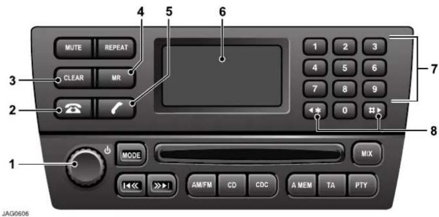
text_image
1 MODE MIX AM/FM CD CDC A MEM TA PTY 2 3 4 5 6 7 8 9 0 1 2 3 4 5 6 7 8 9 10 MODE REPEAT MR MUTE RESET Clear OFF- ON/OFF switch and volume control.
- Phone mode button.
- Clear/correct telephone numbers.
- Phone memory recall button.
- Phone send/end calls
- Display.
- Phone keypad - buttons 0 to 9 (except where touch-screen is fitted).
- Scroll memory location.
Audio panel control functions
The audio panel controls are described below.
Volume control
During a call, the phone volume can be adjusted with the audio panel volume control or the steering wheel switches.
The volume will be memorised for future calls (this will not alter other audio volume settings).
Phone mode

This button will activate the phone mode, ready to make a call. The display will indicate
that phone mode has been selected.
This function can also be controlled from the steering wheel: press and hold button 3, see page 307.
Telephone Operation - Standard
Keypad

Press the digits to enter the required telephone number. Each key press will beep and the digits will be displayed on the audio panel.
The keypad can also be used in Memory Recall (MR), to enter a location number, or to scroll up/down the memory locations.
Clear

Press and release CLEAR to clear the last digit of a telephone number.
Press and hold CLEAR to clear all digits entered.
Send/end

Press this button to dial the entered telephone number. It is also used to end a call that is in progress.
Memory recall

Press to access the phone memory location number. Either a memory location
number can be entered from the keypad, or memory locations can be scrolled up and down from the keypad scroll keys.
This function can also be controlled using steering wheel button 4, see page 307. Press the upper or lower part of the control to seek up or down through the numbers in the phone memory.
Display messages
The following messages may be displayed:
- CALL - There is an incoming call.
- CALLING - A call is being established.
• EMPTY - Memory location is empty. - LOCATION - Memory location number or prompt for memory location number.
• NO SERVICE - No cellular or Bluetooth service is available. - PHONE - System entering phone mode.
- Please Wait - phone book information loading - A short delay will be experienced whilst information is transferred from your mobile phone.
- SIG - System Indicator Gauge: this indicates the current status of the Bluetooth telephone system. If your phone supports the signal strength feature, this information will be displayed.
Telephone Operation - Standard
RECEIVING A CALL
An incoming call automatically switches the sound system into the phone mode. The audio panel display will show CALL and the phone will ring through the vehicle's audio system.
If automatic answer has been set in your phone, the call will be automatically answered by your mobile telephone.
To answer:
Press on the steering wheel or; press on the audio panel.
To end:
Press on the steering wheel or; press the audio panel.
Call line Ident
If the caller has the Call Line Ident (CLI) feature, CALL is shown on the audio panel display, followed by the caller's phone number and name (when available). The display may truncate lengthy names.
REJECTING A CALL

Press CLEAR on the audio panel to reject an incoming call.
MAKING A CALL
When making a call, there are two methods of dialling: keypad and memory search.
Keypad dialling
To dial:
Press and hold 📞 the steering wheel or;
press on the audio panel.
PHONE will be displayed.
Key in the phone number on the audio panel keypad. The number will be displayed.
To connect:
Press ☐ the steering wheel or; press ☐ the audio panel.
The display will show CALLING.
To end:
Press on the steering wheel or; press on the audio panel.
Speed dialling
Note: Speed dialling selects the first nine locations stored in your phone's address book.
To dial:
Press and hold the steering wheel or;
press on the audio panel.
PHONE will be displayed.
On the audio panel keypad, press and hold the required speed dialling memory location number 1 to 9, which corresponds with locations 1 to 9 in your mobile phone's address book.
After three seconds, CALLING will be displayed.
Telephone Operation - Standard
To end:
Press ☐ the steering wheel or; press ☐ the audio panel.
Note: Speed dialling can only be used once your mobile phone's address book has been transferred to the vehicle's phone system. For more information, refer to page 320.
MEMORY RECALL DIALLING
Using audio panel
Press on the audio panel.
Phone will be displayed.
Press the MR button.
LOCATION will be displayed.
On the audio panel keypad, press required memory number 1 to 499.
Note: The location number of phone book entries stored on your mobile phone may vary from those stored in the vehicle phone book.
To connect:
Press 📄 the steering wheel or; press 🌐 the audio panel. The display will show CALLING.
To end:
Press ☐ the steering wheel or; press ☐ the audio panel.
Using steering wheel controls
Press and hold button 3, see page 262.
PHONE will be displayed.
On the audio panel keypad, press required memory number 1 to 749.
To connect:
Press 📊 the steering wheel or; press 🌐 the audio panel. The display will show CALLING.
To end:
Press 📄 the steering wheel or; press 🌐 the audio panel.
LAST NUMBER REDIAL
Note: Last number redial is only supported on systems fitted with the touch-screen.
MULTIZONE VOICE
To transfer control of the phone from the rear of the vehicle to the front, when not on a call, press once.
The display will show Phone In Use.
Press a second time and the display will show Phone.
The rear system is now out of phone mode and the front occupants have full, hands-free control.
To transfer control of the phone during a call, press
For more detailed information, please refer to the Rear Multimedia handbook.
Telephone Operation - Touch-Screen
OVERVIEW
On vehicles fitted with the navigation system, the audio panel keyboard is replaced with touch-screen controls.
Control of the system via the steering wheel controls is unchanged, as described in the previous section.
With the ignition switch in position I or II, pressing the button to the left of the screen will display the following screen controls.

text_image
READY PHONE BOOK NOT READY 1 2 3 4 5 6 7 8 9 * 0 # Menu + C 11:09 AMThe message window to the right of the screen will provide information on the telephone system's status. If the phone is connected correctly then the display will show Phone Connected, or if the phone is not connected to the vehicle, Discover Me will be displayed.
MAKING A CALL
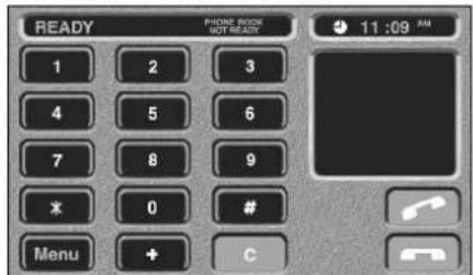
text_image
READY PHONE ROOM NOT READY 1 2 3 4 5 6 7 8 9 * 0 # Menu + C 11:09 AMCalls are made by using the digit and touch-controls, or the memory functions described on page 316.
Erroneous digits can be deleted by touching C.
The number called is displayed at the top of the screen.
The screen will display Calling when establishing a call. On connection,
Connected is displayed and is illuminated.
If the ignition is switched off, the call will be maintained and the touch-screen can be manually turned off. Touch to terminate the call.
Telephone Operation - Touch-Screen
RECEIVING A CALL
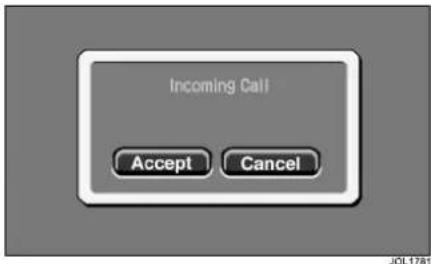
text_image
Incoming Call Accept CancelOn receipt of a call, the screen will display Incoming Call regardless of the audio system operating mode.
This is accompanied by Accept and Cancel touch-controls, enabling the user to answer the call or cancel it.
END CALL FUNCTION
A telephone icon is displayed whenever a telephone call is in progress.
The icon is displayed during an incoming call and during an outgoing call.
The telephone call may be ended by touching the icon.

Telephone call is in progress. Call may be ended by touching this icon.
OTHER FUNCTIONS
Using the menu

text_image
PHONE MENU Search By Name Cancel Location Number Last Number Redial Not Available ListJOL3495
Touch Menu to display the above screen. This screen provides access to memory functions and last number redial.
When the vehicle is in motion, it will not be possible to use the Name touch-control.
Last number redial

text_image
PHONE MENU Search By Name Cancel Location Number Last Number Redial Not Available ListJOL3495
The Last Number Redial memory function enables the user to quickly recall the previously used number.
Use of the List touch-control will display the last ten numbers dialled.
Note: Last Number Redial recalls the last ten numbers called from your mobile phone, if your phone supports this feature.
With certain mobile phones, the last number redial may work in reverse order. This is the way the phone sends the call stack to the vehicle's system.
Telephone Operation - Touch-Screen
Searching by Name
It is possible to list names stored in the vehicle phone book, whilst the vehicle is in motion.

WARNING:
Jaguar recommends that the driver does not use this feature whilst the vehicle is in motion. Give full attention to driving - safe driving is your first responsibility.
Location number

text_image
LIST BY LOCATION 6 Kathryn Dovey 01472002416 7 Stuart Gibbs 01476203789 8 L Williams 07481357902 101 Robert Watts 01712458729 103 Clive Roberts 02986202538 Cancel JOL2718The Location Number screen enables the user to search the phone memory by location.
Upon pressing the location number touch-control, a location number is requested. A list of locations is then displayed as above (dependent upon those stored in the memory). The desired location may then be dialled by touching the location number.
When the vehicle is in motion, the scroll touch-controls at the right-hand side of the touch-screen will be inhibited for safety.
Note:
The location number of phone book entries stored on your mobile phone may vary from those stored in the vehicle phone book.
Telephone Operation - Touch-Screen
Name entry
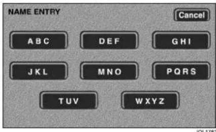
text_image
NAME ENTRY Cancel A B C D E F G H I J K L M N O P Q R S T U V W X Y ZOn the phone menu, select Name. The screen above will be displayed. Touch the required alphabetical group to narrow your search, then scroll through the list.
List by name
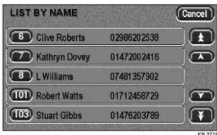
text_image
LIST BY NAME 6 Clive Roberts 02986202538 7 Kathryn Dovey 01472002416 8 L Williams 07481357902 101 Robert Watts 01712458729 103 Stuart Gibbs 01476203789 Cancel JOL 2719With the memory list displayed above, scroll through the list of names using the arrowed buttons. Touch the desired list number to make the call.
Use to terminate the call.
MULTIZONE VOICE
To transfer control of the phone from the rear of the vehicle to the front, when not on a call, press once.
The display will show Phone In Use.
Press a second time and the screen below will be displayed:
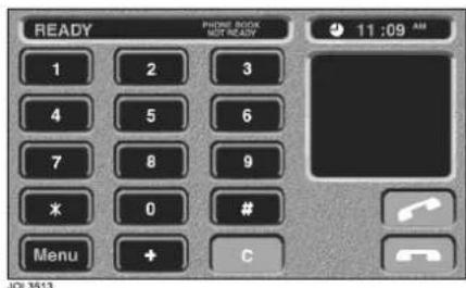
text_image
READY Phone BOOK NOT READY 1 2 3 4 5 6 7 8 9 * 0 # Menu + C 11:09 AM JOL3513The rear system is now out of phone mode and the front occupants have full hands-free control.
To transfer control of the phone during a call, press
For more detailed information, please refer to the Rear Multimedia handbook.
ADDITIONAL INFORMATION
Continuity of calls
Whilst in a call in hands-free mode, the call remains connected if the vehicle ignition is turned OFF (position 0). When the call ends, another call cannot be made or received through the vehicle system unless the ignition switch is turned to position I or II.
Telephone Operation - Touch-Screen
DTMF tones
Whilst in a call you can transmit a DTMF (Dual Tone Multi-Frequency) tone, to remotely control equipment such as an answering machine. Key in the appropriate numbers on the audio panel keypad. The numbers entered will be displayed on the audio panel.
Scratch pad
During a call, the audio panel keypad may be used to store a number to be dialled once the current call is terminated. The number entered will be displayed on the audio panel: once the current call is terminated, the number can be dialled by pressing ☐ the steering wheel, or ☐ on the audio panel.
Note: DTMF tones may be heard when entering a number.
Changing a phone number
When making a call, you can change the phone number shown on the audio display using the CANCEL button (audio panel) or C (touch-screen).
A momentary press erases any single digit, a long press erases the complete number.
PIN feature
The PIN feature is not supported by the Bluetooth telephone system.
Therefore, please ensure that your mobile phone is not locked by a PIN whilst it is connected to the Bluetooth telephone system.
Phone Book
PHONE BOOK TRANSFERS
Any phone numbers stored in your mobile phone book can be copied to the vehicle's phone system.
In most cases, this will happen automatically when you pair the phone with the vehicle. Refer to www.jaguar.com to check compatibility.
However, with some mobile phones, you may need to manually transfer the phone book.
- Make sure the vehicle ignition is ON and the vehicle and phone are paired.
- Press the button on the audio panel or touch-screen surround.
- Switch OFF the ignition and wait for your phone to disconnect from the vehicle, to allow the vehicle Bluetooth system to complete the download process.
Updating the phone book
Once the phone book has been copied to the vehicle, it will be updated automatically if your phone supports automatic phone book download.
Certain phones allow single or multiple phone book entries to be transferred to the vehicle (refer to the manual of your specific mobile phone for more information). These entries will be added to the end of the vehicle phone book.
Note: The location number of phone book entries stored on your mobile phone may change once they are transferred to the vehicle phone book: location numbers are not preserved when phone books are copied via Bluetooth.
If you wish to pair a new phone with the vehicle and replace the current vehicle phone book, follow the relevant pairing procedure on page 308.
Phone Book
Phone book capacity
| Mobile Phone Configuration Vehicle | Phone Book Capacity |
| Phone supports phone memory and SIM card downloads. | 750 (phone memory takes priority over the SIM card). |
| Phone only supports phone memory downloads. | 750 (from phone memory). |
| Phone only supports SIM card downloads. | 750 (from SIM card). |
| Phone doesn’t support phone memory or SIM card downloads. | 0. |
The system can store a maximum of 750 entries, but this figure varies, depending on the type of mobile phone used.
Certain mobile phones store the phone book in two different areas: the SIM card and the phone memory. With some mobile phones, it is not possible to transfer addresses stored in one or both of these areas. The table above explains how this affects the number of entries that can be stored in the vehicle phone book.
Note: Certain mobile phones do not allow phone book entries stored on the SIM card to be transferred via Bluetooth. However, it may be possible to transfer the SIM phone book to the mobile phone's memory, before copying it to the vehicle phone book. Refer to your mobile phone manual for more information.
Phone book suffixes
With some mobile phones, it is possible to store phone numbers in different categories:
- Work/Office
- Mobile
- Home.
If numbers are stored in your mobile phone in these categories, the vehicle phone book will add a suffix to each entry: WK (work/office), MN (mobile) or HM (home).
This enables the system to handle contacts who have several different phone numbers.
EUROPEAN UNION DIRECTIVES CONFORMANCE STATEMENT

Hereby, Jaguar Cars Limited declares that this product is in compliance with:
- The essential requirements and other relevant provisions of Directive 1999/5/EC.
The Bluetooth word mark and logos are owned by the Bluetooth SIG, Inc. and any use of such marks by Jaguar Cars Limited is under licence. Other trademarks and trade names are those of their respective owners.
EXPORT CONTROLS
This product contains commodities, technology or software exported from the United States in accordance with the Export Administration regulations. Diversion contrary to U.S. or Canadian law is prohibited.
FCC/INDUSTRY CANADA NOTICE
This device complies with Part 15 of the FCC rules. Operation is subject to the following two conditions: (1) this device may not cause harmful interference, and (2) this device must accept any interference received, including interference that may cause undesired operation.
FCC ID: LHJ ***
IC: 2807E ***
Changes or modifications not expressly approved by the party responsible for compliance could void the user's authority to operate the equipment.
Note: This equipment has been tested and found to comply with the limits for a Class B digital device, pursuant to part 15 of the FCC Rules. These limits are designed to provide reasonable protection against harmful interference in a residential installation.
This equipment generates, uses and can radiate radio frequency energy and, if not installed and used in accordance with the instructions, may cause harmful interference to radio communications. However, there is no guarantee that interference will not occur in a particular installation.
If this equipment does cause harmful interference to radio or television reception, which can be determined by turning the equipment off and on, the user is encouraged to try to correct the interference by one or more of the following measures:
- Re-orient or relocate the receiving antenna.
- Increase the separation between the equipment and receiver.
- Connect the equipment into an outlet on a circuit different from that to which the receiver is connected.
- Consult the dealer or an experienced radio/TV technician for help.
JaguarVoice
Introduction
JaguarVoice provides a safe and convenient way of controlling the following vehicle systems (where fitted):
- Sound system (radio, single CD player and CD changer – as applicable)
- In-car telephone
- Climate control system (front user only unless - zone climate control is fitted)
The system is controlled by the Voice button on the left-hand side of the steering wheel and also in the rear multimedia switchpack (if fitted).
See the illustrations on the following pages.

WARNING:
Concentrate on the current road conditions and driving the vehicle at all times. If the voice system does prompt you for a response it will repeat that prompt twice giving you up to 15 seconds to respond. If driving conditions mean that you are unable to respond, the voice system will timeout, cancel the task and will not make any changes to the vehicle settings.
Language and accent
Commands are given in English using a natural speaking voice, without pausing between words. Most accents are understood without difficulty, but the system also allows you to train the voice system with your voice if required, see Voice Training on page 337.
JaguarVoice
Steering wheel voice switches

text_image
1 2 3 4 JAG0593- Message centre display.
- Voice button.
- Mode button, on radio.
- Seek/tuning control, on radio (used to commence voice training).
The rear switchpack (where fitted) located in armrest

text_image
LISTENING 1 2 3 4 5 6 LEFT RIGHT TITLE 1 2 3 I ME MODE 4 5 6 A L I C3 SELECT 7 8 9 V O R D SELECT SET UP C S U T O * S U P P A F D S P T E X T TV STORE 7JAG0656
- Volume - left.
- Headphone mode - left.
- Cabin mode.
- Voice text.
- Headphone mode - right.
- Volume - right.
- Voice button – right.
- Voice button - left.
JaguarVoice
Using the System
Initialisation
JaguarVoice is ready to operate ten seconds after the ignition switch is turned to position II, the system is enabled.
Driver voice controls
The voice button is on the left-hand side of the steering wheel, see Steering wheel voice switches on page 324.
Some examples of using the system are provided on the following pages for you to try.
Note: The system will not operate until the radio security code has been entered.
Rear occupant voice controls
There are two voice buttons on the rear multimedia switchpack, for example see Voice button – left on previous illustration.
These can be operated in two different modes:
Cabin mode – When the cabin mode button is pressed, or when the light on the button is illuminated, then the rear occupants can control the audio playing through the cabin speakers. Simply press the voice button and give a command.
Headphone mode – When the LEFT button is pressed, or when the light on the button is illuminated, then the left occupant is in headphone mode (the control of the right-hand headphones is identical).
In headphone mode, each occupant can control the audio in their own headphones by using their respective voice button, and issuing a voice command.
JaguarVoice
First try some of these commands:
Tuning the radio
| Your instructions to the system System response | |
| Press and release the voice button ‘Beep’ | |
| After the beep say ‘Radio tune 98.9 FM’ | The system responds with:‘Radio tune 98.9 FM’ and tunes the radio to this frequency |
Now try entering a frequency of your own preference, see How to Say Numbers on page 331.
Storing a nametag to this station
| Your instructions to the system System response | |
| Press and release the voice button ‘Beep’ | |
| After the beep say ‘Radio store name’ | The system responds with: ‘Radio store name, Name Please’ |
| Press and release the voice button ‘Beep’ | |
| After the beep say ‘My favourite station’ | The system responds with:‘My favourite station, please say yes or no’ |
| Press and release the voice button ‘Beep’ | |
| After the beep say ‘Yes’ | After a few seconds the system responds with:‘My favourite station stored’ |
Recalling the nametag you have just stored
| Your instructions to the system System response | |
| Press and release the voice button ‘Beep’ | |
| After the beep say ‘Radio tune my favourite station’ | The system responds with:‘Radio tune my favourite station’ and tunes the radio to the frequency stored with this name |
Now try storing a nametag of your choice, and then recalling it.
JaguarVoice
Entering a phone number
| Your instructions to the system System response | |
| Press and release the voice button ‘Beep’ | |
| After the beep say ‘Phone enter zero one six one four’ | The system responds with:‘Phone enter oh one six one four, ...... Continue entering digits or say dial, store, correction or cancel’ |
| Press and release the voice button ‘Beep’ | |
| After the beep say ‘nine six oh nine nine eight’ | The system responds with:nine six oh nine nine eight, ...... Continue entering digits or say dial, store, correction or cancel’ |
| Press and release the voice button ‘Beep’ | |
| After the beep say ‘Cancel’ The system responds with:‘Enter cancel’ | |
Now try entering a phone number of your choice and try some of the following commands:
- DIAL, dials the number entered.
- STORE, stores a nametag of your choice (as in the above example with RADIO STORE NAME).
- CORRECTION, deletes the last string of digits entered, and allows you to re-enter them.
- CANCEL, cancels the command.
Note: When entering a number of your choice, remember numbers can only be given as single digits, but you can enter the digits in as many groups as you like.
Also, when the system has read out the numbers you have entered, you do not have to wait for the 'Continue entering digits' prompt. Simply press the voice button and continue with your dialogue.
JaguarVoice
Operating tips
- After pressing the voice button, wait for the end of the single listening beep before giving the command.*
'LISTENING' will be displayed on the instrument pack or on the rear multimedia switchpack. - Face forward and speak naturally, as if you were talking to a passenger or on the phone.
- Note the structure of the commands; remember this rather than trying to remember all the commands.
Device Function Setting

'Radio Tune 97.4'
- If you forget any of the commands, try saying 'VOICE HELP'. The system will then give you a list of help menus available, from which you can choose the appropriate one for the command you need.
- The Voice system will repeat the command back to you and display it on the message centre or rear multimedia switchpack. The command will then be performed.
- If you hear a double beep when you give a command, press the voice button and try again.*
* A single beep denotes when the voice system is listening for a command. A double beep denotes when the system has stopped listening, due to an error or when an incorrect command has been given.
Command confirmation
After a command has been given, the system will give feedback of what it understood. The verbal feedback can be switched on or off by saying 'VOICE FEEDBACK ON' or 'VOICE FEEDBACK OFF'. Verbal feedback for help commands, directory listings, prompts, error messages and nametags cannot be switched off.
For the 'PHONE DIAL' commands, the system will prompt for confirmation before making the call. This confirmation can be switched on or off by saying 'PHONE CONFIRMATION ON' or 'PHONE CONFIRMATION OFF.'
For each voice command there is an associated visual confirmation, which is shown on the front instrument pack or on the rear multimedia switchpack.
Voice system prompts
During some commands and for voice training, you will be asked by the system for a reply. In such cases you must press and release the voice button then speak after the beep. The system will remind you twice so don't worry about having to respond to the system immediately.
JaguarVoice
Nametags
Nametags are a unique name or phrase of your choice which can be used to recall a radio station or dial a phone number.
For radio commands, 'PHONE DIAL
For phone commands, 'RADIO TUNE
A spoken list of current nametags can be heard by giving the appropriate directory command.
• 'RADIO DIRECTORY'
• 'PHONE DIRECTORY'
There are also commands for deleting either individual names in a directory, or a complete directory, see Voice Command List on page 332.
Hints on storing nametags
- You will have greater success of recalling, and remembering, nametags of two, three, or four words in length. Although nametags of one word in length are also acceptable.
- For best results, store nametags in a quiet environment, i.e. with the windows and sunroof closed, try not to be travelling at speeds above 100 km/h (60 mph), and ask other occupants to be quiet.
- Try not to store a nametag that sounds similar to a nametag already stored, or to any of the commands recognized by the system.
In addition, for phone nametags, do not use numbers, and for radio nametags, try not to use radio frequencies.
Volume level adjustment
The verbal feedback volume level can be adjusted independently for the JaguarVoice system. To adjust, operate the sound system volume control or the steering wheel volume control whilst the voice system is being used. The speaker volume level can also be adjusted within the volume preset menu of the audio system.
JaguarVoice
Some useful notes:
- Only one person at a time can use the voice system.
- Excessive noise, for example while driving with windows open or in demist mode, may cause voice command misrecognition. If it is too noisy to use the phone, it is likely that voice commands will not be recognised.
- Voice commands cannot be given while hands-free phone call or radio traffic announcement is in progress.
- If the voice button is pressed whilst a radio traffic announcement is in progress, the announcement will be cancelled. Press the voice button again to start a voice session.
-
While 'LISTENING' is displayed on the message centre, the command can be cancelled by pressing the same voice button (could be a rear voice button) that was used to start the voice session, except when using the 'PHONE ENTER' command. To cancel a 'PHONE ENTER' voice session either say 'CANCEL' when 'LISTENING' is displayed or press the voice button and after the end of the beep say 'CANCEL'. During a store nametag session, if the voice button is pressed and released during 'LISTENING', the system will cancel after up to two seconds.
-
Voice feedback can be interrupted by pressing the voice button that was used to start the voice session, whilst the feedback is playing.
- After starting to speak, the command must be completed within ten seconds.
- During a voice command the audio system and direction indicator ticking will be muted.
- The voice session will be cancelled if an alternative message requires the display/speaker (e.g. incoming phone call or radio traffic announcement).
JaguarVoice
How to Say Numbers
Numbers in voice commands must be given as shown below. Either 'zero' or 'oh' can be used for '0', most users will find that 'zero' gives better results. For information about specific commands, see Voice Command List on page 332.
Radio stations
Frequencies are said as in the following examples:
- 'Tune five thirty one AM', or 'Tune five thirty one' (531).
• 'Tune nine hundred' (900).
• 'Tune fourteen forty' (1440).
• 'Tune fifteen oh three AM' (1503).
• 'Tune ten eighty' (1080). - 'Tune eighty nine point nine FM' or 'Tune eighty nine point nine' (89.9).
- 'Tune ninety point zero' or 'Tune ninety' (90.0).
• 'Tune one hundred point five' (100.5) - 'Tune one oh one point one FM' (101.1).
- 'Tune one oh eight point oh', 'Tune one oh eight point zero', or 'Tune one oh eight' (108.0).
Disc and track numbers
For CD commands, say disc and track numbers as in the following examples:
• 'Disc one' (1).
• 'Disc six track ten' (6, 10).
• 'Track twenty five' (25).
• 'Track forty seven' (47).
Phone numbers
All phone numbers are said as single digits, as in the following example. Double, Triple and Treble are also acceptable commands if preceding a single digit. Plus (+), Star (*) and Hash (#) are acceptable as the first digit of a number.
- 'Dial zero one two zero three four zero two one double four' (01203 402144). When using the Phone Enter command, the first entry must be between 2 – 16 digits, then, 1 – 16 digits to a maximum of 32 in total.
Temperatures
In climate control commands, say temperatures as in the following examples:
• 'Temperature seventy two' (72).
• 'Temperature eighty' (80).
- 'Temperature twenty one point five' (21.5).
- 'Temperature nineteen point zero', 'Temperature nineteen point oh' or 'Temperature nineteen' (19.0).
JaguarVoice
Voice Command List
Certain commands are only available to the driver, these are indicated in the following list.
Key
() denotes an option, i.e. (ON/OFF) use either ON or OFF with this command.
<> indicates where to say a number or stored nametag.
[] denotes an optional word, e.g. 'VOICE [PLAY] DIRECTORY' can be given as 'VOICE DIRECTORY', or 'VOICE PLAY DIRECTORY'.
(front use only) – indicates this command is not available to rear occupants.
General commands
- HELP
- VOICE HELP
Lists all voice command help messages available.
• VOICE MEMORY HELP (front use only)
• VOICE FEEDBACK (ON/OFF) - PHONE CONFIRMATION (ON/OFF) Switches on or off the system confirmation prompt before making a call when using the PHONE DIAL or PHONE MEMORY DIAL command.
- VOICE [PLAY] DIRECTORY (front use only)
- VOICE DELETE MEMORY (A/B) (front use only)
• VOICE DELETE DIRECTORY (front use only)
JaguarVoice
Radio commands
• RADIO PLAY or RADIO ON
Turns the sound system on.
- RADIO OFF
Turns the sound system off. Use this command to turn off the CD or CD changer.
• RADIO SEEK [UP]
• RADIO SEEK DOWN
- RADIO TUNE
See How to Say Numbers on page 331.
(The radio will not respond to Long Wave commands in Australia and New Zealand.)
• RADIO TUNE
- [RADIO] [TUNE] PRESET
Selects the stored station corresponding to the preset number (1 to 9) given in the command.
• [RADIO] [TUNE] [BAND] (MEDIUM WAVE/LONG WAVE/FM)
- RADIO TRAFFIC INFO (ON/OFF)
Turns on or off the Traffic
Announcement (TA) feature.
• RADIO STORE NAME
Stores the currently selected station, with a nametag of your choice. See Storing a nametag to this station on page 326. A total of 20 nametags can be stored.
- [RADIO] STORE PRESET
Stores the currently selected station to the preset given in the command. Note: The sound system must be in radio mode before giving the 'RADIO STORE NAME' or 'RADIO STORE PRESET' command.
• RADIO AUTOSTORE
• RADIO DELETE - RADIO DELETE DIRECTORY
Deletes all currently stored radio nametags.
• RADIO [PLAY] DIRECTORY - RADIO HELP
• RADIO MEMORY HELP
Single CD commands (where fitted)
- CD PLAY or CD ON
- CD [PLAY] TRACK
- CD MIX TRACKS
This will play the tracks of the current disc in a random order.
- CD MIX OFF
- CD HELP
CD changer commands (where fitted)
• CHANGER PLAY or CHANGER ON
- [CHANGER] [PLAY] DISC
- [CHANGER] [PLAY] TRACK
See How to Say Numbers on page 331.
- [CHANGER] [PLAY] DISC
JaguarVoice
- CHANGER MIX TRACKS
This will play the tracks of the current disc in a random order. - CHANGER MIX ALL
This will play all the tracks and discs within the CD changer in a random order. - CHANGER MIX OFF
- CHANGER HELP
Generic track commands
These commands play the current or previous CD, MD or Changer.
Phone commands (where fitted)
Note: In noisy conditions, for example, in heavy rain or driving at high speed on a rough road surface, use the PHONE ENTER command, entering the number in several groups for improved recognition.
- PHONE (ON/OFF)
• [PHONE] ENTER <2 - 16 phone digits>
See How to Say Numbers on page 331.
The system responds to this command by repeating the phone number back to you and then giving you the options below.
Remember to press the voice button to continue with one of the options.
- DIAL
- STORE (give a nametag when prompted as in RADIO STORE NAME, see Storing a nametag to this station on page 326.
- CORRECTION
- CANCEL
For help, see Entering a phone number on page 327.
A total of 40 nametags can be stored.
- (PHONE DIAL/DIAL)
- [PHONE] REDIAL
• [PHONE] DIAL
Calls the phone number stored with the nametag given.
JaguarVoice
- [PHONE] DIAL MEMORY
Calls the phone number stored in the phone memory location given.
See How to Say Numbers on page 331.
Memory numbers 1 – 100 refer to numbers stored in the phone memory and numbers 101 – 249 are numbers stored in the SIM card.
• PHONE STORE
Allows you to store a nametag to the number given in the command.
The system will prompt you with 'NAME PLEASE', press and release the voice button and give a nametag of your choice, as in the RADIO STORE NAME. See Storing a nametag to this station on page 326.
A total of 40 phone nametags can be stored.
See How to Say Numbers on page 331.
See Nametags on page 329.
• PHONE [PLAY] DIRECTORY
- PHONE DELETE
• PHONE DELETE DIRECTORY
Deletes all currently stored phone nametags.
This does not affect numbers stored in the phone memory.
• PHONE CONFIRMATION (ON/OFF)
- PHONE HELP
• PHONE MEMORY HELP
Note:
- When an outgoing phone call is terminated, the sound system will remain in phone mode. To change to another mode, give the appropriate voice command.
- The voice system is inactive while a phone call is in progress.
Automatic climate control commands (where fitted)
• CLIMATE CONTROL ON
• CLIMATE CONTROL OFF
• [CLIMATE CONTROL] AUTOMATIC [ON]
- [CLIMATE CONTROL]
TEMPERATURE
The temperature can be given in Celsius or Fahrenheit, in the range 17 to 31 degrees Celsius (61 to 89 degrees Fahrenheit), in increments of 0.5 degree Celsius (1.0 degree Fahrenheit).
See How to Say Numbers on page 331.
Note: Do not say the word 'Celsius' or 'Fahrenheit'.
• [CLIMATE CONTROL]
TEMPERATURE (HIGH/LOW) (front use only)
- [CLIMATE CONTROL] RECIRC [ON] (front use only)
Recirculation mode, see the owner's handbook for help.
This command will not be executed if the climate control system is in defrost mode.
JaguarVoice
Automatic climate control commands (continued)
• [CLIMATE CONTROL] BALANCE [ON]
When the driver gives this command the temperature of all zones are set to the same as the driver's side temperature. When a rear occupant gives this command the temperature of both rear zones will be set to the same.
- [CLIMATE CONTROL] DEFROST [ON] (front use only)
• CLIMATE CONTROL HELP
• REAR CLIMATE CONTROL OFF
Manual climate control commands (where fitted)
• [CLIMATE CONTROL] RECIRC [ON]
Switches the climate control system to recirc mode (see the owner's handbook for details). This command will be disabled if the climate control system is in defrost mode.
• CLIMATE CONTROL HELP
Gives spoken information about the climate control voice commands.
JaguarVoice
Voice Training
The voice system is able to interpret most English speakers without difficulty. If, however, you find that commands are sometimes not being recognised, you can train the voice system to recognize your voice. The voice system can be trained for two people using voice memories A and B.
After Voice Training, the system will automatically recognise the users whose voices are held in the voice memory. The system can still be used by other users, with no loss of recognition.
Training procedure
Training can only be carried out whilst sitting in the driver's seat.
Give the command 'VOICE DIRECTORY', this will list the memories used and tell you if they are stored with a nametag.
If no memories are in use, either memory can be used.
If both memories are in use and you wish to overwrite one of the memories, select the memory you wish to overwrite.
- First, select which voice memory to train.
- Position the vehicle, with the sunroof and windows closed, in a reasonably quiet outdoor location.
- Sit in the driving seat with the engine running, the handbrake or Electric parking Brake (EPB) on and the transmission in Park or Neutral.
- Press and release the MODE button on the radio (adjacent to the volume control). Mode level 1 will display. Press the MODE button repeatedly until 'ADV MODE N/Y' is displayed. Turn the volume control to select 'ADV MODE YES' Press the MODE button reteatedly until 'VOICE A' is displayed. To select 'VOICE B' press the MODE button again.
- With 'VOICE A' or 'VOICE B' displayed on the radio press the seek up control to start Voice Training. Once you have selected which memory to use, the system gives verbal instructions about the training procedure.
- Follow the instructions given by the system. See Training Command List on page 338.
- To cancel Voice Training at any time press and hold the voice button for five seconds.
Note:
- Some of the phrases which the voice system asks you to repeat during Voice Training are not valid voice commands, these are used to collect specific phonetic phrases required by the system.
- If the user does not speak after a phrase prompt, the voice system will provide two reminder prompts then cancel Voice Training.
- The voice system turns off the phone whilst in training mode, so it will need to be turned on manually after Voice Training has finished.
JaguarVoice
Training Command List
The ‘sounds’ of the following training commands are required for the voice system to ‘learn’, although some of the equipment (TV, navigation, telephone etc.) stated in the commands may not be fitted to a particular vehicle.
- display select twilight colours
- prefer toll roads
- radio ten oh eight AM
- store preset five
- tune one oh five point two FM
- telephone enter eight four six three seven
- select one zero four point nine
- CD changer play disc one track seventy six
- climate temperature twenty five point oh degrees
- radio one oh eight point zero
- phone enter triple three treble zero
- map traffic information off
- voice guidance on
- dial memory two hundred
- teletext page eight four seven
- radio tune thirteen ninety five AM
- select fifteen eighty four medium wave
- changer play CD six track sixty nine
-
navigation select zoom level eleven
-
telephone dial memory fifty two
- climate control balance on
- avoid major roads
- map show complete route
- navigation clear next waypoint
- radio tune one oh seven point one FM
- screen select automatic colours
- repeat last instruction
- phone enter gate double three one oh
- TV channel down
- television seek up
- radio tune two sixteen long wave
- select twelve thirty three medium wave
- voice delete memory A
- climate control seventeen point zero degrees
- navigation show current position
- CD changer play CD two track nineteen
- map zoom out maximum
JaguarVoice
Trouble-shooting Error Messages
In addition to the voice command prompts given by the system, the following error messages may be displayed on the instrument panel display. Most of these messages are accompanied by an advisory double beep.
| Voice Command Group | Message Meaning | |
| General | VOICE NOT READY | The voice system is initialising (when ignition is first turned on). It takes the voice system approximately ten seconds to initialise. |
| NO SPEECH DETECTED | The voice system has not heard any speech.Ensure that the command is given after the end of the beep.Ensure that the command is given within a maximum of five seconds from the end of the beep.Note:Be sure you know what to say before pressing the Voice button.If this error is displayed for all commands given this may indicate a fault with the microphone or microphone wiring, consult your Jaguar Dealer/Authorised Repairer for assistance. | |
| COMMAND CANCELLED | Displayed if the user cancels a voice session during the LISTENING period or another system interrupts the voice session (i.e. incoming phone call or radio traffic announcement). | |
JaguarVoice
| Voice Command Group | Message Meaning | |
| General (continued) | COMMAND NOT RECOGNISED | The voice system has failed to recognise your command.Ensure that the command format is valid, see Voice Command List on page 332.Ensure that the command is given after the end of the beep.Look forward and speak clearly without pausing between words and at a level appropriate to the ambient noise level; imagine you are making a hands-free phone call.Ensure that the ambient noise level is not excessive, for example, windows open or demist on.Note:If it is too noisy to use the phone, it is likely that voice commands will not be recognised.If optional words of the command have been omitted, then the command should be tried with these in place.If a number of commands have been given in rapid succession resulting in the message ‘COMMAND NOT RECOGNISED’ to be displayed, then allow the system to recover (approximately one minute) before trying the command again.If the system consistently fails to recognise commands, the voice training procedure should be carried out to improve the recognition response for the speaker. |
JaguarVoice
| Voice Command Group | Message Meaning | |
| Nametags (continued) | STORE FAILED Displayed when the voice system fails to store a nametag.Possible reasons could be that the nametag is too long or there is too much noise. Try the command again. If the error persists, try storing the nametag under quiet conditions such as with the vehicle parked and the windows closed. | |
| Phone CONNECT | PHONE TRY AGAIN | If the GSM phone is in its cradle but voice system keeps saying ‘dial not accepted, please connect phone and try again’, then the phone handset may not be correctly attached to its storage cradle. Try re-attaching the phone handset. If the problem persists, the phone may be incorrectly reporting its cradle status. Try powering the phone handset off and on to resolve the issue. |
| Voice Training SET | HANDBRAKE TO CONTINUE | This text message is displayed with its associated verbal feedback when the electronic EPB is released during Voice Training. To continue voice training the brake must be re-applied. |
| VOICE TRAINING UNSUCCESSFUL | This text message is displayed with its associated verbal feedback if the voice system could not save the training model recorded. If this problem occurs, please turn the ignition off, wait five seconds, and turn the ignition back on. Please check that there is no abnormal/excessive noise entering the vehicle interior and try running the Voice training procedure again. If the voice system continues to exhibit this error, consult your Jaguar Dealer for assistance. | |
JaguarVoice
| Voice Command Group | Message Meaning | |
| Nametags RADIO | NOT IN TUNER MODE | Displayed when the user tries to store a radio nametag and the radio has not been placed in tuner mode, for example playing a CD. |
| NAMES TOO MUCH ALIKE | This response will be received when storing a nametag if the nametag being given has already been stored. This can be confirmed by giving the RADIO DIRECTORY or PHONE DIRECTORY command.If this response is received and the nametag has not been used already, then it is too similar to an existing nametag or voice grammar and an alternative should be used. | |
| SPOKE DURING LISTENING TONE | Displayed when user utters a radio or phone nametag while the beep is playing. Please wait for the end of the beep then say the nametag. | |
| DIRECTORY FULL The user has tried to add a nametag to a directory that is full. The voice system can store up to 40 phone and 20 radio nametags. | ||
| DIRECTORY EMPTY Displayed when a RADIO DIRECTORY, PHONE DIRECTORY or VOICE DIRECTORY command is given and no nametags have been stored in the associated directory. | ||
| NAMETAG TOO LONG The nametag given is too short (so as not to mistake the nametag for inadvertent noise). If you experience this error please provide a longer nametag. | ||
| STORE CANCELLED Displayed and associated verbal response is provided when a nametag storage session is cancelled by the user. | ||
L
L
JaguarVoice
Index
Adaptive cruise control ..... 139
ACC failure 144
automatic switch off ..... 142
changing the gap 141
changing the set speed.....140
detection issues 143
driving with ACC active. 142
entering the follow mode..... 141
forward alert 144
low speed automatic switch off .. 142
overriding the set speed/follow mode. 142
resuming the set speed/follow mode. 142
setting the vehicle speed ..... 140
Address book 320
Airbag
deactivation warning light ..... 54
deployment 48
disposal 57
driving position 54
fault warning light 48
front protection 50
occupancy sensing 53
rear impact protection.... 52
side protection 51
Airbags 46
Alarms and audible signals ..... 29
audible signals.... 29
error audible signals 30
error flash signals 30
full alarm 29
Alternator.... 227
Anti-lock braking system (ABS)..... 149
Audible warnings. 95
Audio controls 279
Steering wheel controls..... 280
Audio system
audio setup 274
CD changer 289
CD control 286
change audio source 275
digital signal processing ..... 275
radio data systems (RDS) ..... 263
radio operation. 273
single CD player operation..... 286
steering wheel controls ..... 262
Autolamps 110
Automatic car wash 239
Automatic speed limiter 145
Automatic transmission ..... 134
Battery 226
care 226
charging 229
leads disconnection/reconnection 228
reconnection alarm state ..... 32
warning signs 226
Battery-backed sounder 32
Bluetooth description. 304
Bonnet release 215
Bulb renewal 197
access cover 197
front direction indicators ..... 199
front fog lamps. 201
headlamps 197
number plate 201
rear lamps 201
side repeaters 200
sidelamps. 200
Call volume 304
Catalytic converters 164
Changing a phone number ..... 319
Channel automatic tuning ..... 280
Channel options 281
DAB search 282
Finding a channel.... 281, 282
Finding an ensemble 281
Child and infant safety 58
Index
Child safety 58
child restraints securing 62
door locks 27
ISOFIX restraint system. 64
seating positioning 60
Climate control 165
air distribution 167
air recirculation 171
front controls. 168
general points 166
rear controls 172
recommended operation.....165
touch-screen 174
air conditioning 180
AUTO mode 176
blower mute 180
blower speed.... 180
Celsius/Fahrenheit selection . . . 177
climate options 182
controls 175
displays 176
dual temperature zones ..... 177
external temperature..... 177
heated screens and mirrors ... 179
latched air recirculation..... 178
manual air distribution..... 180
ram air 181
rear climate panel 182
smog sensing 182
switching off 181
temperature selection ..... 177
timed air recirculation ..... 178
windscreen defrost/demist .... 179
Clock setting 73,268
Compact disc changer
CD check sequence. 289
CD selection.... 290
CDC button 290
display panel 290
loading discs into the magazine . 289
mix 290
operation 289
pause 291
repeat. 291
seek up and down 290
Cruise (speed) control ..... 137
changing the set speed ..... 137
resuming the set speed ..... 137
setting the vehicle speed ..... 137
Declaration of conformity. 322
Diesel engines
running out of fuel 162
Diesel particle filter.... 161
regeneration.... 161
Dimmer switch 115
Disability modifications 48
Display options
DAB radio text 280
Driving position 54
DTMF tones 319
Dynamic stability control ..... 147
Electric Parking Brake (EPB) ..... 124
Electrical accessories 242
Emergency starting 185
Engine oil
diesel engine 218
petrol engine 217
Entry/exit mode 74
EPB 124
Fire extinguisher.... 213
First aid kit 153
Floor mat retention. 9
Foreign travel 153
Index
Fuel and refuelling 157
filling the tank 157
fuel capacity 158
fuel flap manual release ..... 163
fuel gauge 89
Fuel requirements diesel engines .... 160
Fuses.... 203
checking and renewing 203
fuse box locations 204
fuse positions 206
before programming 34
erase all programming. 34
programming the vehicle. 34
rolling code programming ..... 35
Gearshift interlock ..... 14, 134
General driving information ..... 152
General information.... 5,260
Hazard warning 113
Headlight convenience 30
Health and safety 12
Ignition switch 14
gearshift interlock 14
steering column lock 14
to remove the key 14
Immobilisation system. 15
Inclination sensing.... 31
Inertia switch 184
Instruments 87
warning indicators. 90
Interior features 125
accessory power points ..... 125
centre console.... 127
horn 119
lighter and ashtray.... 125
picnic tray 130
rear armrest.... 128
sun visors and mirrors. 126
sunblinds 129
sunglasses stowage ..... 126
Introduction
audio systems 253
automatic climate control ..... 252
in-car telephone 255
JaguarVoice 255
navigation system 254
rear multimedia 255
screen cleaning 252
television system 255
window tinting 255
Intrusion sensing 31
Jaguar Dealers 6
Jaguar diagnostic system 8
data recording 11
JaguarVoice
command confirmation ..... 328
command list 332
how to say numbers.... 331
introduction 323
language and accent 323
nametags 329
operating tips 328
rear switchpack 324
steering wheel voice switch ..... 324
training
training command list..... 338
training procedure 337
trouble-shooting error messages. 339
useful notes 330
using the system 325
voice system prompts 328
volume level adjustment ..... 329
Key transmitter.... 17
battery renewal 18
Keys 16
additional keys 16
black-headed key.... 16
green-headed valet key 16
integrated key transmitter ..... 16
Lamp
bulb failure 113
Index
Lamps
approach 113
battery saver.... 115
daylight running.... 111
dimmer switch.... 115
direction indicators ..... 112
door guard/puddle 113
entry/exit 114
exit delay 110
fog lamps 111
hazard warning 113
headlamp convenience ..... 110
headlamp levelling..... 111
interior 114
master switch 109
reading/map 114
rear interior 114
Leather care 10
Locking and unlocking 20
alarms and audible signals ..... 29
auto-relocking 24
central locking.... 21
drive-away door locking ..... 21
global closing 22
global opening. 24
luggage compartment. 28
single or two-stage 23
smart locking.... 22
Luggage compartment 86
underfloor access 187
Maintenance
battery 226
bonnet release. 215
brake fluid 221
check and top-up 217
engine coolant. 224
engine oil 217
power steering 220
regular checks. 214
reservoir and dipstick locations .. 216
tyres. 231
windscreen wash fluid.....223
Memory setting 84
recalling 84
setting procedure.... 84
Message centre 97
messages.... 97
Message list. 99
Mirrors 80
door mirrors 80
interior rear view mirror 81
Mobile/portable telephones ..... 9
Occupancy sensing 53
Occupant protection 40
Pairing 308
Panic alarm 31
Parkbrake.... 124
Parking assist.... 116
Parking brake.... 124
Parts and accessories 6
Passive arming.... 32
Pedal adjustment 76
Phone book 320
Preset buttons 283
Recalling a preset channel..... 283
Storing channels as presets .... 283
Radio
auto memory 271, 276
automatic volume control ..... 268
band switch 270
change audio source 270
digital signal processing ..... 269
display panel 268
mode level 1.... 268
ON/OFF and volume 268
presetting memorised stations .. 270
priority programme type (PPTY) . 265
programme type (PTY).... 265
RDS operation 264
RDS trouble-shooting guide .... 267
reception 263
seek and manual tuning..... 270
source tone memory 270
TA operation 265
Index
Radio frequency approval ..... 19
Radio set up 271
Rear impact protection 56
Rear Seat Entertainment (RSE) controls. 270
Regular servicing.... 8
Restraints system 46
Roof rack.... 153
Seat belts 40
Beltminder 42
fitting 43
height adjustment 44
pregnant women 45
Seats 68
adjustment. 68
front seat adjustment 68
head restraint adjustment ..... 69
rear seat adjustment 70
seat heaters....71
Security code number 260
Security features 31
battery reconnection 32
battery-backed sounder ..... 32
inclination (tilt) sensing 31
intrusion sensing 31
panic alarm 31
passive arming 32
Service interval indicator.... 98
Settings 284
Announcements 284
DAB country 284
DAB format 285
Single CD player
CD button 286
display panel 286
eject and CD-in indicator ..... 286
mix. 286
repeat 286
seek up and down.... 286
Sport mode 136
Starting/stopping the vehicle ..... 131
before starting 131
starting a diesel engine ..... 132
starting a petrol engine ..... 131
Steering column adjustment ..... 74
Steering column lock 14
Steering wheel controls 307
Sunroof. 120
to open the sunroof 120
Telephone 304
PIN 319
Safety 305
Standard 311
Making a call 313
Memory recall dialling ..... 314
Multizone voice 314
Receiving a call 313
Rejecting a call.... 313
System overview 304
Touch-screen. 315
Making a call 315
Multizone voice 318
Receiving a call 316
Television
basic controls. 294
change screen mode 301
introduction 293
teletext 302
to set country of operation..... 300
TV tuning 297
Touch-screen. 252
Touch-screen controls
Last number redial 316
List by name. 318
Location number 317
Name entry.... 318
Touch-screen display.... 256
brightness/contrast 258
menu 257
system setup 258
volume preset 257
Touring 153
Towing a caravan or trailer..... 155
Index
Trip computer 106
average fuel consumption..... 106
average speed.... 106
clearing messages 108
current fuel consumption ..... 106
display 106
odometer.... 106
range 106
setting 107
switchpack 107
trip distance 106
Tyre pressure monitoring system . . . 235
Tyres 231
damage 234
renewal 234
repair 234
snow chains 238
wear.... 234
winter/snow.... 238
Valet key 25
Vehicle care. 239
alloy road wheels 241
carpets 239
exterior 239
glass surfaces 240
grease and tar 240
interior 239
leather 10
paintwork. 240
underbonnet cleaning 240
washing 239
Vehicle data. 243
dimensions 244
engine details 243
roof rack and trailer 248
tow-bar fixings 156
weights 245
wheels and tyres 249
Vehicle identification 7
Vehicle immobilisation system ..... 15
Vehicle locking 20
Vehicle recovery 194
Vehicle security 15
Vehicle suspension 151
Vehicle unlocking 23
Voice activation 305
Volume 304
Warning indicators 90
Warning triangle.... 154
Warnings, cautions and notes ..... 5
Warranty.... 6
Wheel changing and jacking ..... 187
equipment 189
jacking 190
locking wheel nuts 188
spare wheel 188
wheel changing 190
Wheels and tyres
care 231
tyre pressures 231
Whiplash protection.... 56
Wind resonance 78
Window
operation 77
Window operation 77
anti-trap feature 78
anti-trap feature, resetting ..... 78
raising/lowering 77
Window tinting 9
Winter driving. 153
Wipers and washers 122