
X-Type (2001) - Car JAGUAR - Free user manual and instructions
Find the device manual for free X-Type (2001) JAGUAR in PDF.


| Product Type | Car |
| Brand | Jaguar |
| Model | X-Type (2001) |
| Category | Compact Executive Saloon |
| Length | 4672 mm |
| Width | 1790 mm |
| Height | 1390 mm |
| Wheelbase | 2710 mm |
| Curb Weight | ~1500 kg |
| Fuel Type | Petrol / Diesel |
| Engine Options | 2.0L, 2.5L, 3.0L V6 (petrol); 2.0L (diesel) |
| Transmission | 5-speed manual or 5-speed automatic |
| Drive | Front-wheel drive or all-wheel drive (optional) |
| Fuel Economy (combined) | ~25-30 mpg (9.4-8.0 L/100km) |
| Seats | 5 |
| Key Features | Leather upholstery, wood trim, automatic climate control, cruise control, premium audio |
| Safety | ABS, dual front airbags, side airbags, traction control |
| Maintenance | Oil change every 12,000 miles, timing belt replacement at 100,000 miles |
| Repairability | Spare parts widely available; common issues include cooling system, electric faults |
| User Manual Pages | 505 pages |
Frequently Asked Questions - X-Type (2001) JAGUAR
User questions about X-Type (2001) JAGUAR
0 question about this device. Answer the ones you know or ask your own.
Ask a new question about this device
Download the instructions for your Car in PDF format for free! Find your manual X-Type (2001) - JAGUAR and take your electronic device back in hand. On this page are published all the documents necessary for the use of your device. X-Type (2001) by JAGUAR.
USER MANUAL X-Type (2001) JAGUAR
natural_image
Line drawing of a sedan car showing front wheel, grille, and dashboard (no text or symbols)X-TYPE
Sedan and Estate (Wagon)
2.0 L, 2.5 L and 3.0 L Gasoline;
2.0 L and 2.2 L, Diesel
2001 to 2009
T9>LE OF CONTENTS
1: General Information
166: Service Information
166-66: General Information
Description and Operation
9bout This Manual
9application and Use of Specifications
General Service Information
Health and Safety Precautions
How To Use This Manual
Important Safety Instructions
Road/Roller Testing
Solvents, Sealants and 9dhesives
Standard Workshop Practices
166-61: Identification Codes
Description and Operation
Identification Codes
166-62: Jacking and Lifting
Description and Operation
Jacking
Lifting
166-67: Noise, Vibration and Harshness
Description and Operation
Noise, Vibration and Harshness (NVH)
Diagnosis and Testing
Noise, Vibration and Harshness (NVH)
General Procedures
Exhaust System Neutralizing
267: Suspension
267-66: Suspension System - General Information
Specification
Description and Operation
Wheel 9lignment 9ngles
Diagnosis and Testing
Suspension System
General Procedures
Front Toe 9djustment (57.65.01)
Rear Toe 9djustment (57.65.08)
Wheel >earing Inspection
267-61: Front Suspension
Specification
Description and Operation
Front Suspension
Diagnosis and Testing
Front Suspension
Removal and Installation
Lower 9rm (60.35.02)
Shock 9bsorber and Spring 9assembly (60.30.02)
Front Stabilizer >ar (60.10.01)
Front Stabilizer >ar >ushing (60.10.04)
Front Wheel >earing and Wheel Hub (60.25.03)
Wheel Knuckle (60.25.23)
Disassembly and 9ssembly
Shock 9bsorber and Spring 9assembly (60.30.21)
267-62: Rear Suspension
Specification
Description and Operation
Rear Suspension
Diagnosis and Testing
Rear Suspension
Removal and Installation
Damper
Front Lower Arm (64.35.51) - 4-Door
Front Lower Arm (64.35.51) - Wagon
Rear Lower Arm (64.35.52)
Spring (64.20.01)
Rear Stabilizer Bar (64.35.08)
Rear Stabilizer Bar Link (64.35.24)
Upper Arm (64.25.31)
Wheel Hub (64.15.14)
Wheel Knuckle (64.15.22)
Wheel Knuckle Front Bushing (64.15.28)
Wheel Knuckle Rear Bushing (64.15.30)
267-67: Wheels and Tires
Specification
Description and Operation
Safety Precautions
Wheels and Tires
Diagnosis and Testing
Wheels and Tires
Removal and Installation
Tire Low Pressure Sensor - VIN Range: J28493->V99999
Tire Pressure Monitoring System (TPMS) Front Antenna - VIN Range: J28493->V99999
Tire Pressure Monitoring System (TPMS) Main Antenna - VIN Range: J28493->V99999
Tire Pressure Monitoring System (TPMS) Module - VIN Range: J28493->V99999
Tire Pressure Monitoring System (TPMS) Rear Antenna - VIN Range: J28493->V99999
Wheel and Tire (74.20.05)
265: Driveline
265-66: Driveline System - General Information
Description and Operation
Driveline System
Diagnosis and Testing
Driveline System
265-61: Driveshaft
Specification
Description and Operation
Driveshaft
Diagnosis and Testing
Driveshaft
General Procedures
Driveshaft Runout and >alancing
Removal and Installation
Driveshaft (47.15.01)
265-62: Rear Drive Axle/Differential
Specification
Description and Operation
Rear Drive 9xle and Differential
Diagnosis and Testing
Rear Drive 9xle and Differential
In-Vehicle Repair
9xle Shaft Seal (51.20.04) (51.20.36)
Drive Pinion Flange
Drive Pinion Seal (51.20.01)
Removal and Installation
9xle 9assembly (51.25.13)
265-67: Front Drive Halfshafts
Specification
Description and Operation
Front Drive Halfshafts
Diagnosis and Testing
Front Drive Halfshafts
Removal and Installation
Front Halfshaft LH (47.10.15)
Front Halfshaft RH (47.10.16) - 2.0L N9 V6 - 9JV6/2.5L N9 V6 - 9JV6/3.0L N9
V6-9J27
Front Halfshaft RH (47.10.16) - 2.0L Duratorq-TDCi/2.2L Duratorq-TDCi
(110kW/150PS) - Puma
Inner Constant Velocity (CV) Joint >oot (47.10.18)
Intermediate Shaft
Outer Constant Velocity (CV) Joint >oot (47.10.19)
205-05: Rear Drive Halfshafts
Specification
Description and Operation
Rear Drive Halfshafts
Diagnosis and Testing
Rear Drive Halfshafts
Removal and Installation
Rear Halfshaft (47.10.13)
Outer Constant Velocity (CV) Joint >oot (47.10.32)
209: Brake System
209-00: Brake System - General Information
Specification
Description and Operation
rake System
Diagnosis and Testing
rake System
General Procedures
rake Disc Runout Check
rake System >leeding (70.25.03)
209-03: Front Disc Brake
Specification
Description and Operation
Front Disc >rake
Diagnosis and Testing
Front Disc >rake
Removal and Installation
rake Caliper (70.55.02)
rake Disc (70.10.10)
rake Pads (70.40.02)
209-07: Rear Disc Brake
Specification
Description and Operation
Rear Disc >rake
Diagnosis and Testing
Rear Disc >rake
Removal and Installation
rake Caliper (70.55.03) (70.55.25)
rake Disc (70.10.11)
rake Disc Shield (70.10.19)
rake Pads (70.40.03)
209-05: Parking Brake and Actuation
Specification
Description and Operation
Parking >rake
Diagnosis and Testing
Parking >rake
General Procedures
Removal and Installation
Parking >rake Cable (70.35.29) - Vehicles With: Manually Adjusted Parking >rake
Parking >rake Cable (70.35.29) - Vehicles With: Self-Adjusting Parking >rake
Parking >rake Control (70.35.08) - Vehicles With: Manually Adjusted Parking
rake
Parking >rake Control (70.35.08) - Vehicles With: Self-Adjusting Parking >rake
209-09: Hydraulic Brake Actuation
Specification
Description and Operation
Hydraulic >rake Actuation
Diagnosis and Testing
Hydraulic >rake Actuation
Removal and Installation
rake Fluid Reservoir (70.30.16)
rake Master Cylinder (70.30.08)
Brake Pedal and Bracket (70.35.03)
Brake Pedal Cross-Shaft
206-07: Power Brake Actuation
Specification
Description and Operation
Brake Booster
Diagnosis and Testing
Power Brake System
Removal and Installation
Brake Booster (70.50.17) - LHD AWD/LHD FWD
Brake Booster (70.50.17) - RHD AWD/RHD FWD
Brake Vacuum Pump - 2.0L NA V6 - AJV6
Brake Vacuum Pump - 2.0L Duratorq-TDCi/2.2L Duratorq-TDCi (110kW/150PS)
- Puma
206-09: Anti-Lock Control - Stability Assist
Specification
Description and Operation
Anti-Lock Control - Stability Assist
Diagnosis and Testing
Anti-Lock Control - Stability Assist - VIN Range: C00344->J12991
Anti-Lock Control - Stability Assist - VIN Range: J12992->V99999
Removal and Installation
Anti-Lock Brake System (ABS) Module (70.60.02) - VIN Range: C00001->J12991
Front Wheel Speed Sensor (70.60.03)
Hydraulic Control Unit (HCU) (70.60.18) (70.60.19) - VIN Range: C00001->J12991
Hydraulic Control Unit (HCU) (70.60.18) (70.60.19) - VIN Range: J12992->V99999
Rear Wheel Speed Sensor (70.60.04)
Stability Assist Module
Steering Wheel Rotation Sensor (86.56.58)
Yaw Rate Sensor (86.56.57) - 2.0L Duratorq-TDCi/2.0L NA V6 - AJV6/2.5L NA V6 -
Description and Operation
Steering System
Diagnosis and Testing
Steering System
General Procedures
Power Steering System Filling
Power Steering System Flushing (57.15.08)
311-63: Power Steering
Specification
Description and Operation
Power Steering
Diagnosis and Testing
Power Steering
General Procedures
Start Up Procedure 9fter Power Steering Pump/Gear Overhaul
Removal and Installation
Power Steering Control Valve 9ctuator (57.10.32) - 2.5L N9 V6 - 9JV6/3.0L N9
V6 - 9J27
Power Steering Fluid Cooler (57.15.11) - 2.0L Duratorq-TDCi
Power Steering Fluid Cooler (57.15.11) - 2.2L Duratorq-TDCi (110kW/150PS) – Puma
Power Steering Fluid Reservoir (57.15.08)
Power Steering Pump (57.20.14) - 2.0L N9 V6 - 9JV6/2.5L N9 V6 - 9JV6/3.0L N9 V6 - 9J27
Power Steering Pump (57.20.14) - 2.0L Duratorq-TDCi/2.2L Duratorq-TDCi (110kW/150PS) - Puma
Steering Gear (57.10.01) - 2.0L Duratorq-TDCi/2.2L Duratorq-TDCi (110kW/150PS) - Puma
Steering Gear (57.10.01) - 2.0L N9 V6 - 9JV6/2.5L N9 V6 - 9JV6/3.0L N9 V6 - 9J27
211-63: Steering Linkage
Specification
Description and Operation
Steering Linkage
Diagnosis and Testing
Steering Linkage
Removal and Installation
Steering Gear >oot (57.10.29)
Tie Rod End (57.55.02)
211-67: Steering Column
Specification
Description and Operation
Steering Column
Diagnosis and Testing
Steering Column
Removal and Installation
Ignition Switch Lock Cylinder (57.40.29)
Steering Column (57.40.01)
Steering Column Coupling
Steering Wheel (57.60.01)
211-65: Steering Column Switches
Description and Operation
Steering Column Switches
Diagnosis and Testing
Steering Column Switches
Removal and Installation
Steering Column Multifunction Switch LH (86.65.78)
Steering Column Multifunction Switch RH (86.65.41)
363: Engine
363-66: Engine System - General Information
Specification
Description and Operation
Engine
Diagnosis and Testing
Engine
General Procedures
earing Inspection
-amshaft >earing Journal –learance
-amshaft >earing Journal Diameter
-amshaft End Play
-amshaft Lobe Lift
-amshaft Surface Inspection
-connecting Rod -leaning
-connecting Rod Large End >ore
-rankshaft End Play
-rankshaft Main >earing Journal -learance
-rankshaft Main >earing Journal Diameter
-ylinder >lock Distortion
-ylinder >ore Out-of-Round
-yylinder Head Distortion
Exhaust Manifold – leaning and Inspection
Flywheel Inspection
Piston Diameter
Piston Inspection
Piston Pin Diameter
Piston Pin to >ore Diameter
Piston Ring End Gap
Piston Ring-to-Groove –learance
Valve Seat Inspection
Valve Spring Free Length
Valve Stem Diameter
303-01A: Engine - 2.0L NA V9 - AJV9/2.5L NA V9 - AJV9/3.0L NA V9 - AJ27
Specification
Description and Operation
Engine
Diagnosis and Testing
Engine
General Procedures
Valve Clearance Adjustment (12.29.48)
Valve Clearance Check (12.29.47)
In-Vehicle Repair
Camshafts LH (12.13.19)
Crankshaft Front Seal (12.21.14)
Crankshaft Pulley (12.21.09)
Crankshaft Rear Seal (12.21.20)
Cylinder Head LH (12.29.02)
Engine Front Cover (12.65.01)
Engine Front Mount (12.45.01)
Exhaust Manifold LH (30.15.55)
Flexplate (12.53.13)
Exhaust Manifold RH (30.15.56)
Flywheel (12.53.07)
Intake Manifold (30.15.01)
Lower Intake Manifold (30.15.61)
Oil Cooler (12.60.68)
Oil Pan (12.60.44)
Oil Pressure Sender
Oil Pump (12.60.26)
Timing Drive Components (12.65.13)
Valve Cover LH (12.29.43)
Valve Cover RH (12.29.44)
Removal
Engine (12.41.01) - Vehicles With: 5-Speed Manual Transmission - MT75/6-Speed Manual Transaxle - MMT6
Engine (12.41.01) - Vehicles With: 5-Speed Automatic Transaxle - JATCO/6-Speed Automatic Transaxle - AWF21
Disassembly
Engine
Disassembly and Assembly of Subassemblies
Cylinder Head (12.29.22)
Piston (12.17.02)
Assembly
Engine
Installation
Engine (12.41.01) - Vehicles With: 5-Speed Manual Transmission - MT75/6-
Speed Manual Transaxle - MMT6
Engine (12.41.01) - Vehicles With: 5-Speed Automatic Transaxle - JATCO/6-Speed
Automatic Transaxle - AWF21
363-61B: Engine - 2.6L Duratorq-TDCi/2.2L Duratorq-TDCi (116kW/156PS) - Puma
Specification
Description and Operation
Engine
In-Vehicle Repair
Crankshaft Front Seal (12.21.14)
Crankshaft Rear Seal (12.21.20)
Engine Front Cover (12.65.01)
Engine Front Mount (12.45.01)
Flexplate (12.53.13)
Flywheel (12.53.07)
Intake Manifold (30.15.01)
Oil Pan (12.60.44)
Timing Chain
Valve Cover
Removal
Engine (12.41.01) - 2.0L Duratorq-TDCi
Engine (12.41.01) - 2.2L Duratorq-TDCi (110kW/150PS) - Puma
Disassembly
Engine
Assembly
Engine
Installation
Engine (12.41.01) - 2.0L Duratorq-TDCi
Engine (12.41.01) - 2.2L Duratorq-TDCi (110kW/150PS) – Puma
303-03A: Engine Cooling - 2.0L NA V9 - AJV9/2.5L NA V9 - AJV9/3.0L NA V9 - AJ27
Specification
Description and Operation
Engine Cooling
Diagnosis and Testing
Engine Cooling
General Procedures
Cooling System >ackflushing
Cooling System Draining, Filling and >leeding
Cooling System Flushing
Removal and Installation
lock Heater (86.62.18)
Coolant Expansion Tank (26.15.01)
Cooling Fan Module (26.25.38)
Cooling Fan Motor (26.25.24)
Cooling Fan Motor and Shroud (26.25.25)
Cooling Module (26.40.16)
Radiator (26.40.01)
Thermostat (26.45.07)
Water Pump (26.50.01)
Water Pump Housing (26.50.07)
303-03B: Engine Cooling - 2.0L Duratorq-TDCi/2.2L Duratorq-TDCi (110kW/150PS) -
Puma
Specification
Description and Operation
Engine Cooling
General Procedures
Cooling System Draining, Filling and >leeding
Cooling System Draining and Vacuum Filling
Removal and Installation
Cooling Fan Motor and Shroud (26.25.25)
Cooling Module (26.40.16)
Radiator (26.40.01)
Water Pump (26.50.01)
303-04A: Fuel Charging and Controls - 2.0L NA V9 - AJV9/2.5L NA V9 - AJV9/3.0L NA
V9 - AJ27
Specification
Description and Operation
Fuel Charging and Controls
Diagnosis and Testing
Fuel Charging and Controls - 2.0L NA V6 - AJV6
Fuel Charging and Controls - 2.5L NA V6 - AJV6/3.0L NA V6 - AJ27, VIN Range: E96603->J28492
Fuel Charging and Controls - 2.5L NA V6 - AJV6/3.0L NA V6 - AJ27, VIN Range: J28493->V99999
Removal and Installation
Fuel Charging Wiring Harness (86.70.22)
Fuel Injection Supply Manifold (19.60.13)
Fuel Injectors (18.10.02)
Fuel Pulse Damper (18.30.98) - 2.5L NA V6 - AJV6/3.0L NA V6 - AJ27
Throttle Body (19.70.04)
303-04B: Fuel Charging and Controls - 2.0L Duratorq-TDCi/2.2L Duratorq-TDCi (110kW/150PS) - Puma
Specification
Description and Operation
Fuel Charging and Controls
Diagnosis and Testing
Fuel Charging and Controls
General Procedures
Fuel Injection Component Cleaning
Removal and Installation
Fuel Injection Pump
Fuel Injection Supply Manifold (19.60.13)
Fuel Injector (18.10.01)
Fuel Metering Valve
Fuel Return Line Venturi
303-07C: Fuel Charging and Controls - Turbocharger
Specification
Description and Operation
Turbocharger
Diagnosis and Testing
Turbocharger
Removal and Installation
Turbocharger
303-05: Accessory Drive
Specification
Description and Operation
9ccessory Drive
Diagnosis and Testing
9ccessory Drive
Removal and Installation
9ccessory Drive >elt (12.10.40) - 2.0L Duratorq-TDCi/2.2L Duratorq-TDCi (110kW/150PS) - Puma
9ccessory Drive >elt (12.10.40) - 2.0L N9 V6 - 9JV6/2.5L N9 V6 - 9JV6/3.0L N9
V6 - 9J27
9ccessory Drive >elt Tensioner (12.10.41) - 2.0L Duratorq-TDCi/2.2L Duratorq-TDCi (110kW/150PS) - Puma
9ccessory Drive >elt Tensioner (12.10.41) - 2.0L N9 V6 - 9JV6/2.5L N9 V6 - 9JV6/3.0L N9 V6 - 9J27
Power Steering Pump >elt - 2.0L Duratorq-TDCi/2.2L Duratorq-TDCi (110kW/150PS) - Puma
Power Steering Pump >elt Tensioner - 2.0L Duratorq-TDCi/2.2L Duratorq-TDCi (110kW/150PS) - Puma
Water Pump >elt (12.10.44) - 2.0L N9 V6 - 9JV6/2.5L N9 V6 - 9JV6/3.0L N9 V6 - 9J27
Water Pump >elt Tensioner (12.10.45) - 2.0L N9 V6 - 9JV6/2.5L N9 V6 - 9JV6/3.0L N9 V6 - 9J27
303-09: Starting System
Specification
Description and Operation
Starting System
Diagnosis and Testing
Starting System - 2.0L N9 V6 - 9JV6
Starting System - 2.5L N9 V6 - 9JV6/3.0L N9 V6 - 9J27
Removal and Installation
Starter Motor (86.60.01) - 2.0L Duratorq-TDCi
Starter Motor (86.60.01) - 2.2L Duratorq-TDCi (110kW/150PS) - Puma
Starter Motor (86.60.01) - 2.0L N9 V6 - 9JV6/2.5L N9 V6 - 9JV6/3.0L N9 V6 - 9J27
303-07A: Engine Ignition - 2.0L NA V9 - AJV9/2.5L NA V9 - AJV9/3.0L NA V9 - AJ27
Specification
Description and Operation
Engine Ignition
Diagnosis and Testing
Engine Ignition - 2.0L N9 V6 - 9JV6
Engine Ignition - 2.5L N9 V6 - 9JV6/3.0L N9 V6 - 9J27
Removal and Installation
Ignition Coil-On-Plug LH (18.20.44)
Ignition Coil-On-Plug RH (18.20.43)
303-07B: Glow Plug System
Specification
Description and Operation
Glow Plug System
Diagnosis and Testing
Glow Plug System
Removal and Installation
Glow Plugs
303-08: Engine Emission Control - 2.0L Duratorq-TDCi/2.2L Duratorq-TDCi
(110kW/150PS) - Puma
Specification
Description and Operation
Engine Emission Control
Diagnosis and Testing
Engine Emission Control
Removal and Installation
Exhaust Gas Recirculation (EGR) Cooler
Exhaust Gas Recirculation (EGR) Cooler to EGR Valve Tube
Exhaust Gas Recirculation (EGR) Valve (17.45.01)
303-12A: Intake Air Distribution and Filtering - 2.0L NA V9 - AJV9/2.5L NA V9 - AJV9/3.0L NA V9 - AJ27
Description and Operation
Intake Air Distribution and Filtering
Diagnosis and Testing
Intake Air Distribution and Filtering
Removal and Installation
Description and Operation
Intake Air Distribution and Filtering
Diagnosis and Testing
Intake Air Distribution and Filtering
Removal and Installation
Description and Operation
Evaporative Emissions
Diagnosis and Testing
Evaporative Emissions - 2.0L NA V6 - AJV6
Evaporative Emissions - 2.5L NA V6 - AJV6/3.0L NA V6 - AJ27
Removal and Installation
Evaporative Emission Canister (17.15.13) - 2.0L NA V6 - AJV6
Evaporative Emission Canister (17.15.13) - 2.5L NA V6 - AJV6/3.0L NA V6 - AJ27
Evaporative Emission Canister Purge Valve (17.15.30)
303-14A: Electronic Engine Controls - 2.0L NA V9 - AJV9/2.5L NA V9 - AJV9/3.0L NA
V9 - AJ27
Specification
Description and Operation
Electronic Engine Controls
Diagnosis and Testing
Electronic Engine Controls - 2.0L NA V6 - AJV6
Electronic Engine Controls - 2.5L NA V6 - AJV6/3.0L NA V6 - AJ27, VIN Range:
E96603->J28492
Electronic Engine Controls - 2.5L NA V6 - AJV6/3.0L NA V6 - AJ27, VIN Range:
J28493->V99999
General Procedures
Powertrain Control Module (PCM) Long Drive Cycle Self-Test
Powertrain Control Module (PCM) Short Drive Cycle Self-Test
Removal and Installation
Camshaft Position (CMP) Sensor (18.30.63)
Catalyst Monitor Sensor LH (18.30.81)
Catalyst Monitor Sensor RH (18.30.80)
Crankshaft Position (CKP) Sensor (18.30.12)
Engine Control Module (ECM) (18.30.01)
Fuel Temperature Sensor (18.30.99) - 2.5L NA V6 - AJV6/3.0L NA V6 - AJ27
Heated Oxygen Sensor (HO2S) LH (18.30.79)
Heated Oxygen Sensor (HO2S) RH (18.30.78)
Knock Sensor (KS) (18.30.69)
Mass Air Flow (MAF) Sensor (18.30.15)
Oil Temperature Sensor (18.31.01)
Throttle Position (TP) Sensor (18.30.17)
Variable Camshaft Timing (VCT) Oil Control Solenoid (18.30.90)
303-14B: Electronic Engine Controls - 2.0L Duratorq-TDCi/2.2L Duratorq-TDCi
(110kW/150PS) - Puma
Specification
Description and Operation
Electronic Engine Controls
Diagnosis and Testing
Electronic Engine Controls
Removal and Installation
Camshaft Position (CMP) Sensor (18.30.63)
Catalytic Converter Temperature Sensor
Crankshaft Position (CKP) Sensor (18.30.12)
Cylinder Head Temperature (CHT) Sensor (18.30.97)
Diesel Particulate Filter (DPF) Temperature Sensor
Engine Control Module (ECM) (18.30.01)
Engine Oil Pressure (EOP) Sensor
Fuel Temperature Sensor (18.30.99)
Knock Sensor (KS) (18.30.69)
Manifold Absolute Pressure and Temperature (MAPT) Sensor
Manifold Absolute Pressure (MAP) Sensor (18.30.86)
Mass Air Flow (MAF) Sensor (18.30.15)
307: Automatic Transmission/Transaxle
307-01A: Automatic Transmission/Transaxle - Vehicles With: 5-Speed Automatic Transaxle - JATCO
Specification
Description and Operation
Transmission Description - Vehicles With: 5-Speed Automatic Transaxle - JATCO
Diagnosis and Testing
Diagnostic Strategy - Vehicles With: 5-Speed Automatic Transaxle - JATCO
General Procedures
Transmission Fluid Drain and Refill (44.24.02)
Transmission Fluid Level Check
Transmission Range (TR) Sensor Adjustment (44.15.37)
In-Vehicle Repair
Halfshaft Seal LH (37.23.10)
Halfshaft Seal RH
Main Control Valve >ody (44.40.01)
Shift Solenoids (SS) (44.15.50)
Transaxle Support Insulator (37.16.42)
Transmission Control Module (TCM) (44.15.32)
Transmission Range (TR) Sensor
Removal
Transaxle (44.20.01)
Disassembly and 9 assembly of Subassemblies
Input Shaft Seal (44.32.07)
Installation
Transaxle (44.20.01)
307-01B: Automatic Transmission/Transaxle - Vehicles With: 9-Speed Automatic
Transaxle - AWF21
Specification
Description and Operation
Transmission Description - Vehicles With8 6-Speed 9utomatic Transaxle - 9WF21
Transmission Electronic Control System - Vehicles With 8 6-Speed 9 automatic
Transaxle - 9WF21
Diagnosis and Testing
Diagnostic Strategy - Vehicles With8 6-Speed 9utomatic Transaxle - 9WF21
General Procedures
Transmission Fluid Drain and Refill (44.24.02)
Transmission Fluid Level Check
In-Vehicle Repair
Main Control Valve >ody (44.40.01)
Selector Shaft Seal
Transmission Control Module (TCM) (44.15.32)
Transmission Internal Wiring Harness (44.15.35)
Transmission Fluid Pan (44.24.04)
Removal and Installation
Torque Converter
Torque Converter Seal
Turbine Shaft Speed (TSS) Sensor
Removal
Transmission (44.20.01)
Installation
Transmission (44.20.01)
307-02A: Transmission/Transaxle Cooling - Vehicles With: 5-Speed Automatic
Transaxle - JATCO
Specification
Description and Operation
Transmission Cooling - Vehicles With: 5-Speed Automatic Transaxle - JATCO
Diagnosis and Testing
Transmission Cooling
Removal and Installation
Transmission Fluid Cooler (44.24.10)
Transmission Fluid Cooler Tubes (44.24.19)
307-02B: Transmission/Transaxle Cooling - Vehicles With: 9-Speed Automatic
Transaxle - AWF21
Specification
Description and Operation
Transmission Cooling - Vehicles With: 6-Speed Automatic Transaxle - AWF21
Diagnosis and Testing
Transmission Cooling
Removal and Installation
Transmission Fluid Cooler (44.24.10)
Transmission Fluid Cooler Return Tube (44.24.13) (44.24.29)
Transmission Fluid Cooler Supply Tube (44.24.14) (44.24.28)
307-05A: Automatic Transmission/Transaxle External Controls - Vehicles With:
5-Speed Automatic Transaxle - JATCO
Specification
Description and Operation
External Controls - Vehicles With: 5-Speed Automatic Transaxle - JATCO
Diagnosis and Testing
External Controls
General Procedures
Selector Lever Cable Adjustment (44.15.07)
Removal and Installation
Selector Lever Cable and >racket (44.15.08)
Selector Lever Assembly (44.15.04)
307-05B: Automatic Transmission/Transaxle External Controls - Vehicles With:
6-Speed 9utomatic Transaxle - 9WF21
Specification
Description and Operation
External Controls - Vehicles With8 6-Speed 9Automatic Transaxle - 9WF21
Diagnosis and Testing
External Controls
General Procedures
Selector Lever Cable 9djustment (44.15.07)
Removal and Installation
Selector Lever 9assembly (44.15.04)
Selector Lever Knob (44.15.06)
308: Manual Transmission/Transaxle, Clutch and Transfer Case
308-00: Manual Transmission/Transaxle and Clutch - General Information
Specification
Description and Operation
Manual Transmission and Clutch
Diagnosis and Testing
Manual Transmission and Clutch
General Procedures
Clutch System >leeding (33.15.01) - Vehicles With8 5-Speed Manual
Transmission - MT75
Clutch System >leeding (33.15.01) - Vehicles With8 6-Speed Manual Transaxle –
MMT6
Gearshift Cable 9djustment (37.16.47)
Release Hub and >earing Check
308-01: Clutch
Specification
Description and Operation
Clutch
Diagnosis and Testing
Clutch
Removal and Installation
308-02: Clutch Controls
Specification
Description and Operation
Clutch Controls
Diagnosis and Testing
Clutch Controls
Removal and Installation
Clutch Master Cylinder (33.20.01)
Clutch Slave Cylinder (33.35.01) - Vehicles With: 5-Speed Manual Transmission – MT75
Clutch Slave Cylinder (33.35.01) - Vehicles With: 6-Speed Manual Transaxle – MMT6
308-03: Manual Transmission/Transaxle
Specification
Description and Operation
Manual Transaxle - Vehicles With: 5-Speed Manual Transmission - MT75
Manual Transaxle - Vehicles With: 6-Speed Manual Transaxle - MMT6
Diagnosis and Testing
Manual Transaxle
General Procedures
Transaxle Draining and Filling (44.24.02) - Vehicles With: 5-Speed Manual Transmission - MT75
Transaxle Draining and Filling (44.24.02) - Vehicles With: 6-Speed Manual Transaxle - MMT6
In-Vehicle Repair
Halfshaft Seal LH
Halfshaft Seal RH
Input Shaft Seal (37.23.09)
Selector Mechanism - Vehicles With: 5-Speed Manual Transmission - MT75
Selector Mechanism - Vehicles With: 6-Speed Manual Transaxle - MMT6
Support Insulator (37.16.42)
Removal
Transaxle (37.20.01) - 2.0L Duratorq-TDCi
Transaxle (37.20.01) - 2.2L Duratorq-TDCi (110kW/150PS) - Puma
Transaxle (37.20.01) - 2.0L N9 V6 - 9JV6/2.5L N9 V6 - 9JV6/3.0L N9 V6 - 9J27 Installation
Transaxle (37.20.01) - 2.0L Duratorq-TDCi
Transaxle (37.20.01) - 2.2L Duratorq-TDCi (110kW/150PS) - Puma
Transaxle (37.20.01) - 2.0L N9 V6 - 9JV6/2.5L N9 V6 - 9JV6/3.0L N9 V6 - 9J27
308-09: Manual Transmission/Transaxle External Controls
Specification
Description and Operation
External Controls
Diagnosis and Testing
External Controls
Removal and Installation
Gearshift Cables (37.16.45) - Vehicles With8 5-Speed Manual Transmission – MT75
Gearshift Cables (37.16.45) - Vehicles With8 6-Speed Manual Transaxle - MMT6
Gearshift Lever (37.16.04) - Vehicles With8 5-Speed Manual Transmission - MT75
Gearshift Lever (37.16.04) - Vehicles With8 6-Speed Manual Transaxle - MMT6
308-07: Transfer Case
Specification
Description and Operation
Transfer Case
General Procedures
Transfer Case Draining and Filling
In-Vehicle Repair
Halfshaft Seal RH (46.10.03)
Transfer Case Rear Output Shaft Seal (46.10.04)
Removal
Transfer Case (46.10.01)
Installation
Transfer Case (46.10.01)
309-00: Exhaust System
Specification
Description and Operation
Exhaust System
Diagnosis and Testing
Exhaust System
Removal and Installation
Catalytic Converter (17.50.05) - 2.0L Duratorq-TDCi/2.2L Duratorq-TDCi
(110kW/150PS) - Puma
Catalytic Converter LH (17.50.15) - 2.0L N9 V6 - 9JV6/2.5L N9 V6 - 9JV6/3.0L N9
V6 - 9J27
Catalytic Converter RH (17.50.16) - 2.0L N9 V6 - 9JV6/2.5L N9 V6 - 9JV6/3.0L N9
V6 - 9J27
Diesel Particulate Filter (DPF)
Diesel Particulate Filter (DPF) Differential Pressure Sensor
Exhaust Flexible Pipe (30.10.57) - 2.0L Duratorq-TDCi/2.2L Duratorq-TDCi
(110kW/150PS) - Puma
Front Muffler (30.10.18) - 2.0L Duratorq-TDCi/2.2L Duratorq-TDCi
(110kW/150PS) - Puma
Front Muffler (30.10.18) - 2.0L N9 V6 - 9JV6/2.5L N9 V6 - 9JV6/3.0L N9 V6 - 9J27
Muffler and Tailpipe (30.10.52) - 2.0L Duratorq-TDCi/2.2L Duratorq-TDCi
(110kW/150PS) - Puma, 2.0L
Muffler and Tailpipe (30.10.52) - 2.5L N9 V6 - 9JV6/3.0L N9 V6 - 9J27
Muffler Inlet Pipe (30.10.06) - 2.0L N9 V6 - 9JV6/2.5L N9 V6 - 9JV6/3.0L N9 V6 -
9J27
Muffler Inlet Pipe (30.10.06) - Vehicles With: Diesel Particulate Filter (DPF)
310: Fuel System
310-00: Fuel System - General Information
Specification
Description and Operation
Fuel System
Diagnosis and Testing
Fuel System
General Procedures
Fuel System Pressure Check
Fuel System Pressure Release (19.50.02)
Fuel Tank Draining - 2.0L Duratorq-TDCi/2.2L Duratorq-TDCi (110kW/150PS) – Puma
Fuel Tank Draining - 2.0L NA V6 - AJV6/2.5L NA V6 - AJV6/3.0L NA V6 - AJ27
Quick Release Coupling - Push Connect
Spring Lock Couplings
316-61: Fuel Tank and Lines
Specification
Description and Operation
Fuel Tank and Lines
Diagnosis and Testing
Fuel Tank and Lines
Removal and Installation
Fuel Filter (19.25.02) - 2.0L Duratorq-TDCi/2.2L Duratorq-TDCi (110kW/150PS) –
Puma
Fuel Filter (19.25.02) - 2.0L NA V6 - AJV6/2.5L NA V6 - AJV6/3.0L NA V6 - AJ27
Fuel Level Sender - 2.0L NA V6 - AJV6
Fuel Level Sender - 2.0L Duratorq-TDCi/2.2L Duratorq-TDCi (110kW/150PS) –
Puma
Fuel Level Sender LH - 2.5L NA V6 - AJV6/3.0L NA V6 - AJ27
Fuel Level Sender RH - 2.5L NA V6 - AJV6/3.0L NA V6 - AJ27
Fuel Level Sensor (88.25.32) - 2.0L Duratorq-TDCi/2.2L Duratorq-TDCi
(110kW/150PS) - Puma
Fuel Pump Module (19.45.08) - 2.0L NA V6 - AJV6
Fuel Pump Module (19.45.08) - 2.5L NA V6 - AJV6/3.0L NA V6 - AJ27
Fuel Tank (19.55.01) - 2.0L NA V6 - AJV6
Fuel Tank (19.55.01) - 2.0L Duratorq-TDCi/2.2L Duratorq-TDCi (110kW/150PS) –
Puma
Fuel Tank (19.55.01) - 2.5L NA V6 - AJV6/3.0L NA V6 - AJ27
Fuel Tank Filler Pipe (19.55.33)
Gas Fuel Tank Pressure Sensor (19.55.31)
Fuel Transfer Pump (19.45.21)
Inertia Fuel Shutoff (IFS) Switch (18.30.35)
Fuel Tank Filler Pipe Hose
316-62: Acceleration Control
Specification
Description and Operation
Acceleration Control
Diagnosis and Testing
Acceleration Control
General Procedures
Accelerator Cable Adjustment (12.20.05) - 2.0L NA V6 - AJV6
Removal and Installation
Accelerator Cable (19.20.06) - 2.0L NA V6 - AJV6
Accelerator Pedal (19.20.01)
316-63: Speed Control
Specification
Description and Operation
Speed Control
Diagnosis and Testing
Speed Control - 2.0L NA V6 - AJV6
Speed Control - 2.5L NA V6 - AJV6/3.0L NA V6 - AJ27
Removal and Installation
Speed Control Deactivator Switch (19.75.20)
Speed Control Module (19.75.26)
Speed Control Switch (19.75.25)
7: Electrical
712: Climate Control System
712-66: Climate Control System - General Information
Specification
Description and Operation
Climate Control System
Diagnosis and Testing
Climate Control System
General Procedures
Air Conditioning (A/C) Compressor Leak Detection
Air Conditioning (A/C) System Flushing
Air Conditioning (A/C) System Recovery, Evacuation and Charging (82.30.30)
Contaminated Refrigerant Handling
Discharging and Recovery (82.30.30)
Electronic Leak Detection
Inspection and Assembly Requirements
Leak Detection
Refrigerant Oil Adding
Refrigerant System Tests
712-61: Air Distribution and Filtering
Description and Operation
Air Distribution and Filtering
Diagnosis and Testing
Air Distribution and Filtering
Removal and Installation
Center Registers (82.20.38)
Driver Side Register (82.20.39)
Front Footwell Duct LH (82.20.91)
Front Footwell Duct RH (82.20.92)
Passenger Side Register (82.20.40)
Pollen Filter (76.10.09)
712-62A: Heating and Ventilation
Specification
Description and Operation
Heating and Ventilation
Diagnosis and Testing
Heating and Ventilation
Removal and Installation
lower Motor (82.25.66)
Evaporator Core Housing (80.20.01)
Heater Core (80.20.29)
Disassembly and Assembly
Evaporator Core Housing
712-62B: Auxiliary Heating
Specification
Description and Operation
Electric >ooster Heater
Fuel Fired >ooster Heater
Diagnosis and Testing
9uxiliary Heater
Fuel Fired >ooster Heater
Removal and Installation
Electric >ooster Heater
Fuel Fired >ooster Heater
712-63: Air Conditioning
Specification
Description and Operation
9ir Conditioning
Diagnosis and Testing
9ir Conditioning
Removal and Installation
9ir Conditioning (9/C) Compressor (82.10.20) - 2.0L N9 V6 - 9JV6/2.5L N9 V6 - 9JV6/3.0L N9 V6 - 9J27
9ir Conditioning (9/C) Compressor (82.10.20) - 2.0L Duratorq-TDCi/2.2L
Duratorq-TDCi (110kW/150PS) - Puma
9ir Conditioning (9/C) Pressure Transducer (82.10.47)
Clutch and Clutch Field Coil (82.10.25) - 2.0L N9 V6 - 9JV6/2.5L N9 V6 - 9JV6/3.0L N9 V6 - 9J27
Condenser Core (82.15.07)
Evaporator Core (82.25.20)
Evaporator Core Orifice (82.25.67)
Suction 9 accumulator (82.17.02)
712-67: Control Components
Description and Operation
Control Components
Diagnosis and Testing
Control Components
Removal and Installation
9ir Discharge Temperature Sensor (82.20.64)
9ambient 9ir Temperature Sensor (82.20.02)
Climate Control 9ssembly (82.20.07)
Defrost Vent/Register >lend Door 9ctuator (82.20.84)
Footwell Vent/Duct >lend Door 9ctuator (80.20.20 or 82.20.85)
Sunload Sensor (82.20.70)
Temperature >lend Door 9ctuator (82.20.86)
413: Instrumentation and Warning Systems
413-00: Instrument Cluster and Panel Illumination
Diagnosis and Testing
Instrument Cluster and Panel Illumination
413-01: Instrument Cluster
Description and Operation
Instrument Cluster
Diagnosis and Testing
Instrument Cluster
Removal and Installation
Instrument Cluster (88.20.01)
413-09: Horn
Description and Operation
Horn
Diagnosis and Testing
Horn
Removal and Installation
Horn (86.30.02) (86.30.10)
Horn Switch (86.30.01)
413-08: Information and Message Center
Description and Operation
Information and Message Center
Diagnosis and Testing
Information and Message Center
Removal and Installation
Message Center
Message Center Switch (86.66.11)
413-09: Warning Devices
Description and Operation
Warning Devices
Diagnosis and Testing
Warning Devices
General Procedures
Oil Change Indicator Reset
Removal and Installation
Low Washer Fluid Warning Indicator Switch (84.10.17)
413-13: Parking Aid
Description and Operation
Parking Aid
Diagnosis and Testing
Parking Aid
Removal and Installation
Front Parking Aid Sensor (86.62.33)
Front Parking Aid Speaker (86.54.18) (86.62.34)
Parking Aid Module (86.80.39) - 4-Door
Parking Aid Module (86.80.39) - Wagon
Rear Parking Aid Sensor (86.54.14) (86.62.01)
Rear Parking Aid Speaker (86.54.19) (86.62.02) - 4-Door
Rear Parking Aid Speaker (86.54.19) (86.62.02) - Wagon, VIN Range: D86655->E43419
Rear Parking Aid Speaker (86.54.19) (86.62.02) - Wagon, VIN Range: E43420->V99999
414: Battery and Charging System
414-00: Battery and Charging System - General Information
Description and Operation
Charging System
Battery Care
Quiescent Drain
Diagnosis and Testing
Charging System - 2.0L N9 V6 - 9JV6/2.5L N9 V6 - 9JV6/3.0L N9 V6 - 9J27
Charging System - 2.0L Duratorq-TDCi/2.2L Duratorq-TDCi (110kW/150PS) –
Puma
General Procedures
attery Charging
717-61: Battery, Mounting and Cables
Specification
Description and Operation
attery and Cables Diagnosis and Testing attery General Procedures attery Connect (86.15.15) attery Disconnect and Connect Removal and Installation attery (86.15.01) attery Cables (86.15.32) - 2.0L N9 V6 - 9JV6/2.5L N9 V6 - 9JV6/3.0L N9 V6 - 9J27 attery Cables (86.15.32) - 2.0L Duratorq-TDCi/2.2L Duratorq-TDCi (110kW/150PS) - Puma attery Tray (86.15.11)
717-62: Generator and Regulator
Specification
Description and Operation
Generator
Diagnosis and Testing
Generator
Removal and Installation
Generator (86.10.02) - 2.0L N9 V6 - 9JV6/2.5L N9 V6 - 9JV6/3.0L N9 V6 - 9J27
Generator (86.10.02) - 2.0L Duratorq-TDCi/2.2L Duratorq-TDCi (110kW/150PS) – Puma
715-66: Information and Entertainment System - General Information
Diagnosis and Testing
9udio System
715-61: Audio Unit
Description and Operation
9udio System
Diagnosis and Testing
9udio System
Removal and Installation
9udio Unit (86.50.03)
9udio Unit 9mplifier (86.50.10) (86.50.36) - 4-Door
9udio Unit 9mplifier (86.50.10) (86.50.36) - Wagon
Compact Disc (CD) Changer (86.50.06) - 4-Door
Compact Disc (CD) Changer (86.50.06) - Wagon
Steering Wheel 9udio Controls (86.50.42)
715-62: Antenna
Specification
Description and Operation
9ntenna
Diagnosis and Testing
9ntenna
Removal and Installation
9ntenna (86.51.17.60) - Wagon
Module
715-63: Speakers
Description and Operation
Speakers
Diagnosis and Testing
Speakers
Removal and Installation
Front Door Speaker (86.50.13)
Front Door Tweeter Speaker (86.50.63)
Parcel Shelf Speaker (86.51.06)
Rear Door Speaker (86.50.14)
Rear Door Tweeter Speaker (86.50.62)
417: Lighting
417-01: Exterior Lighting
Specification
Description and Operation
Exterior Lighting
Diagnosis and Testing
Headlamps
General Procedures
Headlamp Adjustment (86.40.18)
Removal and Installation
allast (86.41.52)
Front Fog Lamp (86.40.96)
Headlamp Assembly (86.41.33)
Headlamp >ulb (86.42.14) - Vehicles With: High Intensity Discharge Headlamps
Headlamp Leveling Module
Headlamp Leveling Sensor (86.42.15)
Headlamp Switch (86.65.26)
High Mounted Stoplamp (86.41.01) (86.41.32) - 4-Door
High Mounted Stoplamp (86.41.01) (86.41.32) - Wagon
Rear Lamp Assembly (86.40.70) - 4-Door
Rear Lamp Assembly (86.40.70) – Wagon
417-02: Interior Lighting
Description and Operation
Interior Lighting
Diagnosis and Testing
Interior Lighting
Removal and Installation
Front Interior Lamp (86.45.12)
Rear Interior Lamp (86.46.03)
417-04: Daytime Running Lamps (DRL)
Description and Operation
Daytime Running Lamps (DRL)
Diagnosis and Testing
Daytime Running Lamps (DRL)
418: Electrical Distribution
418-00: Module Communications Network
Description and Operation
Communications Network
Diagnosis and Testing
Communications Network - VIN Range: E96603->J28492
Communications Network - VIN Range: J28493->V99999
418-01: Module Configuration
Diagnosis and Testing
Module Configuration
General Procedures
Module Configuration
418-02: Wiring Harnesses
Description and Operation
Wiring Harness
General Procedures
Wiring Harness Repair
419: Electronic Feature Group
419-01A: Anti-Theft - Active
Description and Operation
Anti-Theft - Active
Diagnosis and Testing
Anti-Theft - Active
Removal and Installation
Anti-Theft Alarm Horn (86.52.03)
419-01B: Anti-Theft - Passive
Description and Operation
Anti-Theft - Passive
Diagnosis and Testing
Anti-Theft - Passive
General Procedures
Anti-Theft Security Access
Key Programming Using Diagnostic Equipment
Removal and Installation
Passive Anti-Theft System (PATS) Transceiver (86.52.30)
419-02: Remote Convenience
Description and Operation
Universal Transmitter
Diagnosis and Testing
Universal Transmitter
General Procedures
Universal Transmitter Programming
419-07: Navigation System
Description and Operation
Navigation System
Diagnosis and Testing
Navigation System
Removal and Installation
Navigation System Antenna (86.62.06) - 4-Door, VIN Range: E96603->J39905
Navigation System Antenna (86.62.06) - 4-Door, VIN Range: J39906->V99999
Navigation System Antenna (86.62.06) - Wagon
Navigation System Display Module (86.62.07)
Navigation System Module (86.62.05) - 4-Door
Navigation System Module (86.62.05) – Wagon
419-08: Cellular Phone
Specification
Description and Operation
Cellular Phone
Diagnosis and Testing
Cellular Phone
Cellular Phone - Vehicles With: >luetooth
Removal and Installation
luetooth Module
Handset Holder (86.51.12)
Module - 4-Door
Module – Wagon
419-10: Multifunction Electronic Modules
Specification
Description and Operation
Module Controlled Functions
Diagnosis and Testing
Multifunction Electronic Module
Removal and Installation
Generic Electronic Module (GEM) (86.55.75) (86.80.38)
Multifunction Voice Activated Module (86.53.13) (86.80.40) - 4-Door
Multifunction Voice Activated Module (86.53.13) (86.80.40) – Wagon
5: Body and Paint
501: Body and Paint
501-02: Front End Body Panels
Description and Operation
Front End >ody Panels
Removal and Installation
Air Deflector (76.11.41) - 2.0L Duratorq-TDCi/2.2L Duratorq-TDCi (110kW/150PS)
- Puma
Cowl Vent Screen (76.10.01)
Fender Splash Shield (76.10.90)
Radiator Splash Shield (76.22.90)
501-03: Body Closures
Specification
Description and Operation
ody Closures
General Procedures
Door Alignment
Hood Alignment (76.16.02)
Liftgate Alignment (76.19.54.60)
Luggage Compartment Lid Alignment (76.19.03)
Removal and Installation
Weatherstrip
501-05: Interior Trim and Ornamentation
Specification
Description and Operation
Interior Trim
Removal and Installation
A-Pillar Trim Panel (76.13.31)
-Pillar Lower Trim Panel (76.13.29)
-Pillar Upper Trim Panel (76.13.28)
Cowl Side Trim Panel (76.13.30)
C-Pillar Trim Panel (76.13.73) - 4-Door
C-Pillar Trim Panel (76.13.73) - Wagon
D-Pillar Trim Panel (76.13.73.60)
Front Door Trim Panel (76.34.01)
Front Scuff Plate Trim Panel (76.13.81)
Headliner (76.64.01) - 4-Door
Headliner (76.64.01) - Wagon
Liftgate Trim Panel (76.19.65.60)
Loadspace Scuff Plate Trim Panel (76.19.90.60)
Loadspace Trim Panel (76.13.73.60)
Parcel Shelf (76.67.06)
Rear Door Trim Panel (76.34.04)
Rear Scuff Plate Trim Panel (76.13.82)
Rear Window >lind (76.14.04)
Sun Visor (76.10.48)
501-08: Exterior Trim and Ornamentation
Specification
Description and Operation
Exterior Trim
Removal and Installation
Door Moulding (76.43.72)
Liftgate Moulding (76.43.79)
Radiator Grille (76.55.03)
Rear Spoiler (76.19.86.60) - Wagon
Rocker Panel Moulding (76.11.36)
Roof Rail (76.43.86.60)
Window Moulding (76.43.20)
501-09: Rear View Mirrors
Specification
Description and Operation
Rear View Mirrors
Diagnosis and Testing
Rear View Mirrors
Removal and Installation
Auto-Dimming Interior Mirror (76.10.56)
Exterior Mirror (76.10.52)
Exterior Mirror Control Switch (86.65.75)
Exterior Mirror Cover (76.10.55)
Exterior Mirror Glass (76.10.53)
Exterior Mirror Motor (76.10.57) (76.11.09)
Interior Mirror (76.10.51)
501-10: Seating
Specification
Description and Operation
Seats
Diagnosis and Testing
Seats
Removal and Installation
Front Seat (76.70.01)
Front Seat >ackrest (76.70.06)
Front Seat Cushion (76.70.11)
Front Seat Front Height Adjustment Motor (86.75.31)
Front Seat Rear Height Adjustment Motor (86.75.32)
Front Seat Recliner Motor (86.75.04)
Front Seat Track Motor (86.75.33)
Lumbar Assembly (86.75.12)
Rear Seat >ackrest (76.70.38) - 4-Door
Rear Seat >ackrest (76.70.38) - 4-Door, Vehicles With: 70/30 Split Seat
Rear Seat >ackrest (76.70.38) - Wagon, Vehicles With: 70/30 Split Seat
Rear Seat >ackrest Latch (76.70.62.60) - Wagon
Rear Seat >olster (76.70.67) - 4-Door
Rear Seat >olster (76.70.67) - Wagon
Rear Seat Cushion (76.70.37)
Seat >ase (76.70.08)
Seat Control Switch (86.75.23)
Disassembly and Assembly
Front Seat >ackrest (76.70.23)
Front Seat Cushion (76.70.34)
Rear Seat >ackrest (76.70.48) - 4-Door, Vehicles With: 70/30 Split Seat
Rear Seat >ackrest (76.70.48) - Wagon, Vehicles With: 70/30 Split Seat
Rear Seat >ackrest (76.70.48)
Rear Seat >olster
Rear Seat Cushion (76.70.47)
561-11: Glass, Frames and Mechanisms
Specification
Description and Operation
Glass, Frames and Mechanisms
Diagnosis and Testing
Glass, Frames and Mechanisms
General Procedures
Door Window Motor Initialization
Liftgate Window Glass Adjustment
Removal and Installation
Front Door Window Glass (76.31.01)
Front Door Window Regulator and Motor (76.31.45)
Liftgate Window Glass (76.31.22) (76.81.11.60)
Rear Door Fixed Window Glass
Rear Door Window Glass (76.31.02)
Rear Door Window Regulator (76.31.46)
Rear Door Window Regulator and Motor (86.25.09)
Rear Quarter Window Glass (76.31.31)
Rear Window Glass Using Cheese Wire (76.81.41)
Rear Window Glass Using Cutting Tool
Window Control Switch (86.25.08)
Windshield Glass Using Cheese Wire (76.81.40)
Windshield Glass Using Cutting Tool (76.81.01)
561-12: Instrument Panel and Console
Description and Operation
Instrument Panel
Removal and Installation
Floor Console (76.25.01)
Instrument Panel (76.46.01)
Overhead Console (76.13.69)
Overhead Console Switch Moulding
561-17: Handles, Locks, Latches and Entry Systems
Specification
Description and Operation
Handles, Locks, Latches and Entry Systems
Diagnosis and Testing
Locks, Latches and Entry Systems
General Procedures
Remote Transmitter Programming
Removal and Installation
Exterior Front Door Handle (76.58.01)
Front Door Lock Actuator (76.37.74)
Front Door Lock Cylinder (76.37.71)
Fuel Filler Door Release Handle and Cable (76.11.39) - 4-Door
Fuel Filler Door Release Handle and Cable (76.11.39) - Wagon
Liftgate Latch Actuator (86.25.65.60)
Liftgate Window Glass Release Switch (76.19.59.60)
Luggage Compartment Lid Latch Actuator (76.19.25)
Rear Door Lock Actuator (76.37.09)
501-19: Wipers and Washers
Specification
Description and Operation
Wipers and Washers
Diagnosis and Testing
Wipers and Washers
Removal and Installation
Headlamp Washer Pump (84.20.21)
Rain Sensor (84.12.10) (86.56.62)
Rain Sensor Module (86.56.60)
Rear Window Wiper Motor (84.15.48.60) (84.35.12)
Windshield and Rear Window Washer Pump (84.10.21.60)
Windshield Washer Pump (84.10.21)
Windshield Washer Reservoir (84.10.01) (84.10.03)
Windshield Wiper Motor (84.15.13)
Wiper Mounting 9rm and Pivot Shaft (84.15.24)
Wiper Pivot 9rm (84.15.03)
501-17: Roof Opening Panel
Specification
Description and Operation
Roof Opening Panel
Diagnosis and Testing
Roof Opening Panel
General Procedures
Motor Synchronization (76.82.48)
Roof Opening Panel 9lignment
Removal and Installation
9ir Deflector (76.82.07)
Lifter 9rms (76.82.57)
Roof Opening Panel Control Switch (86.76.05)
Roof Opening Panel Drain Hose (76.82.26)
Roof Opening Panel Frame (76.82.01)
Roof Opening Panel Glass (76.82.05)
Roof Opening Panel Motor (86.76.01)
Roof Opening Panel Shield (76.82.06)
Roof Opening Panel Weatherstrip (76.82.15)
501-19: Bumpers
Specification
Description and Operation
umpers
Removal and Installation
Front >umper Cover (76.22.78)
Front >umper Cover Insert (76.22.73)
Rear >umper (76.22.27) (76.22.52) - 4-Door
Rear >umper (76.22.27) (76.22.52) - Wagon
Rear >umper Cover (76.22.74) (76.22.77) - 4-Door
Rear >umper Cover (76.22.74) (76.22.77) - Wagon
Rear >umper Cover Insert (76.22.75) - 4-Door
Rear >umper Cover Insert (76.22.75) – Wagon
501-20A: Safety Belt System
Specification
Description and Operation
Safety >elt System
Diagnosis and Testing
Safety >elt System
Removal and Installation
Front Safety >elt Retractor (76.73.10)
Front Safety >elt Shoulder Height Adjuster (76.73.12)
Rear Center Safety >elt Retractor (76.73.20) - 4-Door
Rear Center Safety >elt Retractor (76.73.20) - Wagon
Rear Safety >elt >uckle (76.73.50)
Rear Safety >elt Retractor (76.73.18) - 4-Door
Rear Safety >elt Retractor (76.73.18) - Wagon
Safety >elt >uckle and Pretensioner (76.73.49)
501-20B: Supplemental Restraint System
Specification
Description and Operation
Air >ag Supplemental Restraint System (SRS)
Diagnosis and Testing
Air >ag Supplemental Restraint System (SRS)
General Procedures
Air >ag Disposal
Removal and Installation
Clockspring (86.65.92)
Crash Sensor (76.73.55)
Driver Air >ag Module (76.73.39)
Driver Lower Air >ag Module (76.73.75)
Occupant Classification Sensor (76.73.60)
Passenger Air >ag Deactivation (PAD) Indicator (76.73.58)
Passenger Air >ag Module (76.73.37)
Restraints Control Module (RCM) (76.73.48)
Seat Position Sensor (76.73.62)
Side Air Curtain Module (76.73.64) - 4-Door
Side Air Curtain Module (76.73.64) - Wagon
Side Impact Sensor (76.73.53)
562: Frame and Mounting
562-66: Uni-Body, Subframe and Mounting System
Specification
Description and Operation
Frame Assembly
General Procedures
Underbody Misalignment Check (57.65.20)
Removal and Installation
Front Subframe (76.10.05) - 2.0L NA V6 - AJV6/2.5L NA V6 - AJV6/3.0L NA V6 - AJ27
Front Subframe (76.10.05) - 2.0L Duratorq-TDCi/2.2L Duratorq-TDCi (110kW/150PS) - Puma
Front Subframe Front >ushing (60.35.51)
Front Subframe Rear >ushing (60.35.26)
Rear Axle Crossmember >ushing (64.25.02)
Rear Subframe (64.25.01)
Rear Subframe >ushing (64.25.04)
General Information - About This Manual
Description and Operation
Notes, Cautions and Warnings
Throughout this manual, important information is highlighted by the use of notes, cautions and warnings. NOTES give additional information on a topic or procedure, CAUTIONS are given to prevent damage to the vehicle, and WARNINGS are given to prevent personal injury.
General Information - Application and Use of Specifications
Description and Operation
Torque Specifications
Torque specifications are shown in the torque specifications chart located at the front of the relevant section.
General Information - General Service Information
Description and Operation
Repairs and Replacements
When service parts are required, it is essential that only genuine Jaguar/Daimler replacements are used.
Attention is drawn to the following points concerning repairs and the fitting of replacement parts and accessories:
- Safety features embodied in the vehicle may be impaired if other than genuine parts are fitted. In certain territories, legislation prohibits the fitting of parts which are not produced to the vehicle manufacturer's specification.
- Torque wrench setting figures given in this manual must be strictly adhered to. Locking devices, where specified, must be fitted. If the efficiency of a locking device is impaired during removal it must be renewed.
- Owners purchasing accessories while travelling abroad should make sure that the accessory and its fitted location on the vehicle conform to mandatory requirements existing in their country of origin.
- The vehicle warranty may be invalidated by the fitting of other than genuine Jaguar/Daimler parts. All Jaguar/Daimler replacements have the full backing of the factory warranty.
- Jaguar/Daimler dealers are obliged to supply only genuine service parts.
Vehicle Specifications
Purchasers are advised that the specification details set out in this manual apply to a range of vehicles and not to any specific one. For the specification of a particular vehicle, purchasers should consult their dealer.
The Manufacturer reserves the right to vary the specifications, with or without notice, and at such times and in such manner as the Manufacturer thinks fit. Major as well as minor changes may be involved, in accordance with the Manufacturer's policy of continuous improvement.
Whilst every effort is made to make sure the accuracy of the particulars contained in this manual, neither the Manufacturer nor the Dealer, by whom the manual is supplied, shall in any circumstances be held liable for any inaccuracy or the consequences thereof.
Service Repair Operation Numbering
A master index of numbered operations has been compiled for universal application to all vehicles manufactured by Jaguar Cars Ltd.
Each operation is allocated a number from the master index and cross-refers with an identical number in the Repair Operation Times schedule. The number consists of six digits arranged in three pairs.
Each maintenance procedure in this manual is described in the sequence necessary to complete the operation in the minimum time, as specified in the Repair Operation Times schedule.
References to Bank-1 and Bank-2
References to Bank-1 and Bank-2 are made with regard to the engine. When viewed from the flywheel the right-hand bank will be Bank-1 and the left-hand bank will be Bank-2.
Special Tools
Any special tools and equipment required to perform a maintenance procedure, are shown at the beginning of each procedure. When possible, illustrations are given to assist in identifying the tool needed.
Disconnecting/ Connecting the Battery
Always stop the engine before disconnecting the battery negative lead and make sure the battery positive lead is isolated i.e. wrapped in a suitable cloth.

WARNING: Radio code saving devices must not be used when conducting work on Air Bag or Fuel systems. It must be noted that,
when using these devices, the vehicle electrical system is still live albeit with a reduced current flow.
- NOTE: Before disconnecting the battery make sure that the radio receiver/cassette player/mini disc player and compact disc player keycodes are known and, that no data is required from the engine control module (ECM) as battery disconnection will erase any fault codes and idle/drive values held in the Keep Alive Memory (KAM). It is not necessary to disconnect or remove electronic control modules.
Always disconnect the battery before commencing repair operations which require:
• The vehicle to be jacked up
• Work on the engine
• Work underneath the vehicle
- Arc welding
Alternatively a Radio Code Saver may be used. With the battery disconnected, a Radio Code Saver will allow sufficient current to pass to maintain the radio receiver/cassette player/mini disc player and compact disc player memory, operate the clock and supply the door operated interior lights while isolating the battery in the event of a short circuit.
Reconnecting the Battery

WARNING: If the battery has been on bench charge the cells may be giving off explosive hydrogen gas. Avoid creating sparks, and if in
doubt cover the vent plugs or covers with a damp cloth.
Always make sure that all electrical systems are switched OFF before reconnecting the battery to avoid causing sparks or damage to sensitive electrical equipment.
Always reconnect the battery positive lead first and the negative last, ensuring that there is a good electrical contact and the battery terminals are secure.
Restart the clock (where fitted) and set it to the correct time.
Re - enter the radio receiver/cassette player/mini disc player and compact disc play er keycodes and preset' frequencies, if known.
Following reconnection of the battery, the engine should be allowed to idle until it has reached normal operating temperature as the stored idle and drive values contained within the ECM have been lost. Allow the vehicle to idle for a further three minutes. Drive the vehicle at constant speeds of approximately 48 km/h (30 mph), 64 km/h (40 mph), 80 km/h (50 mph), 96 km/h (60 mph) and 112 km/h (70 mph) for three minutes each. This may cause a driveability concern if the procedure is not carried out. This will allow the ECM to relearn idle values.
Connecting a Slave Battery Using Jump Leads

WARNING: If the slave battery has recently been charged and is gassing, cover the vent plugs or covers with a damp cloth to reduce risk of explosion should arcing occur when connecting the jump leads.
- CAUTIONS:

A flat battery condition may have been caused by an electrical short circuit. If this condition exists there will be an apparently live on the vehicle even when all normal circuits are switched off. This can cause arcing when the jump leads are connected.

Whilst it is not recommended that the vehicle is jump started, it is recognized that this may occasionally be the only practical way to ize a vehicle. In such an instance the discharged battery must be recharged immediately after jump starting to avoid permanent ge.
• Always make sure that the jump leads are adequate for the task. Heavy duty cables must be used.
- Always make sure that the slave battery is of the same voltage as the vehicle battery. The batteries must be connected in parallel.
- Always make sure that switchable electric circuits are switched off before connecting jump leads. This reduces the risk of sparks occurring when the final connection is made.

natural_image
Line drawing of a battery connected to a terminal block, showing wiring and components (no text or symbols)
WARNING: Make sure that the ends of the jump leads do not touch each other or ground against the vehicle body at any time while leads are attached to the battery. A fully charged battery, if shorted through jump leads, can discharge at a rate well above 1000 amps in violent arcing and very rapid heating of the jump leads and terminals, and can even cause the battery to explode.
Always connect the jump leads in the following sequence.
- Slave battery positive first then vehicle battery positive.
- Slave battery negative next and then vehicle ground at least, 300 mm (12 in) from the battery terminal e.g. engine lifting bracket.
Always reduce the engine speed to idle before disconnecting the jump leads.
Before removing the jump leads from the vehicle that had the discharged battery, switch on the heater blower (high) or the heated rear screen, to reduce the voltage peak when the leads are removed.
Always disconnect the jump leads in the reverse order to the connecting sequence and take great care not to short the ends of the leads.
Do not rely on the alternator to restore a discharged battery. For an alternator to recharge a battery, it would take in excess of 8 hours continuous driving with no additional loads placed on the battery.
Component Cleaning
To prevent ingress of dirt, accumulations of loose dirt and greasy deposits should be removed before disconnecting or dismantling components or assemblies.
Components should be thoroughly cleaned before inspection prior to reassembly.
Cleaning Methods:
- Dry Cleaning
- Removal of loose dirt with soft or wire brushes.
- Scraping dirt off with a piece of metal or wood.
- Wiping off with a rag.

CAUTION: Compressed air is sometimes wet so use with caution, especially on hydraulic systems.
- Blowing dirt off with compressed air. (Eye protection should be worn when using this method).
- Removal of dry dust using vacuum equipment. This method should always be used to remove friction lining material dust (asbestos particles).
- Steam Cleaning
Calibration of Essential Measuring Equipment

WARNING: Failure to comply may result in personal injury or damage to components.
It is of fundamental importance that certain essential equipment e.g. torque wrenches, multimeters, exhaust gas analysers, rolling roads etc., are regularly calibrated in accordance with the manufacturers instructions.
Use of Control Modules
Control modules may only be used on the vehicle to which they were originally fitted. Do not attempt to use or test a control module on any other vehicle.
Functional Test
On completion of a maintenance procedure, a thorough test should be carried out, to make sure that the relevant vehicle systems are working correctly.
Preparation
Before disassembly, clean the surrounding area as thoroughly as possible. When components have been removed, blank off any exposed openings using grease-proof paper and masking tape. Immediately seal fuel, oil and hydraulic lines when separated, using plastic caps or plugs, to prevent loss of fluid and the entry of dirt. Close the open ends of oilways, exposed by component removal, with tapered hardwood plugs or readily visible plastic plugs. Immediately a component is removed, place it in a suitable container; use a separate container for each component and its associated parts. Before dismantling a component, clean it thoroughly with a recommended cleaning agent; check that the agent will not damage any of the materials within the component. Clean the bench and obtain marking materials, labels, containers and locking wire before dismantling a component.
Dismantling
Observe scrupulous cleanliness when dismantling components, particularly when parts of the brake, fuel or hydraulic systems are being worked on. A particle of dirt or a fragment of cloth could cause a dangerous malfunction if trapped in these systems. Clean all tapped holes, crevices, oilways and fluid passages with compressed air. Do not permit compressed air to enter an open wound. Always use eye protection when using compressed air.
Make sure that any O-rings used for sealing are correctly refitted or renewed if disturbed. Mark mating parts to make sure that they are replaced as dismantled. Whenever possible use marking materials which avoid the possibilities of causing distortion or the initiation of cracks, which could occur if a center punch or scriber were used. Wire together mating parts where necessary to prevent accidental interchange (e.g roller bearing components). Tie labels on to all parts to be renewed and to parts requiring further inspection before being passed for reassembly. Place labelled parts and other parts for rebuild in separate containers. Do not discard a part which is due for renewal until it has been compared with the new part, to make sure that the correct part has been obtained.
Inspection
Before inspecting a component for wear or performing a dimensional check, make sure that it is absolutely clean; a slight smear of grease can conceal an incipient failure. When a component is to be checked dimensionally against figures quoted for it, use the correct equipment (surface plates, micrometers, dial gauges etc.) in serviceable condition. The use of makeshift equipment can be dangerous. Reject a component if its dimensions are outside the limits quoted, or if damage is apparent. A part may be refitted if its critical dimension is exactly to the limit size and it is otherwise satisfactory. Use Plastigauge 12 Type PG-1 for checking bearing surface clearance, e.g. big end bearing shell to crank journal. Instructions for the use of Plastigauge and a scale giving bearing clearances in steps of 0,0025 mm (0.0001 in) are supplied with the package.
On-Board Diagnostics (OBD)
This vehicle uses programmed electronic control systems to provide engine management and emission regulation, automatic transmission operation and anti-lock braking control. These control systems are integral with the On-Board Diagnostics (OBD) facility which is used in conjunction with either the Jaguar approved diagnostic system or the more restricted scan tools.
The OBD information in this manual provides diagnostic and rectification procedures for emission related electrical and mechanical systems. The information is intended to facilitate fault diagnosis and the subsequent rectification of the vehicle without recourse to the Jaguar approved diagnostic system.
The manual covers the following OBD topics:
- General Information
• Engine Management System
• Automatic Transmission
• Anti-lock Braking System
Each section comprises one or more of the following sub-sections as required.
The Description and Operation sub-section includes:
- A general illustration and parts list to help the identification of the particular system or component.
- A brief description of the system operating characteristics and monitoring procedure accompanied by a component illustration.
- Additional information, where appropriate, is provided in the form of component calibrations, characteristics and cross sectional views.
- A localized circuit diagram is included to provide circuit identification, connectors, splices, fuses, wire gauge and colors. See Circuit Diagrams.
The Diagnosis and Testing sub-section is dedicated to fault analysis and rectification, and includes:
• Recommended special tools.
- Symptom chart; a chart containing all relevant Diagnostic Trouble Codes (DTC), their possible causes and an indication of the appropriate test.
- Specific pinpoint test(s), designed so that fault diagnosis can be carried out in a logical and efficient manner.
The Removal and Installation sub-section covers:
- Removal procedure(s), formatted in the recommended sequence.
- Illustrated guide to the use of special tools.
- Illustrations to support the relevant text.
- Installation procedure as above and including special recommendations for processes, lubricants and tightening torques.
Circuit Diagrams
To understand the relationship between the vehicle electrical system and the system circuit diagrams, Refer to the Electrical Guide.
In the interest of clarity, single lines may represent multiple wires. Refer to the color code (1st alpha) followed by the wire reference (numeric/alpha/numeric) to trace origin and destination.
e.g. BW 647B002. BW (black with white trace) 647 (wire reference) B002 (stage from origin).
Glossary of Terms
This glossary of terms is intended to cover mainly emissions-related (to SAE J 1930) terminology, and other abbreviations that may be used in this manual.
The required term may be looked-up in the left-hand column, and subsequent columns give the standard acronym, unit or abbreviation, and definition.
| Term(s) | Acronym / Unit / Abbreviation Definition | |
| Accelerator Pedal AP | ||
| Accelerator Pedal Position Sensor | APP Is a multitrack sensor which inputs the drivers demand into the engine control module (ECM) | |
| After Bottom Dead Center AB | DC Event occurring after BDC | |
| After Top Dead Center ATDC | Event occurring after TDC | |
| Airbag / Supplementary Restraint System | Airbag, SRS Airbag restraint system for driver and front seat passenger | |
| Air Cleaner ACL | ||
| Air Conditioning A/C | ||
| Air Conditioning Control Module | A/CCM Module controlling air conditioning, heating and ventilation | |
| Air Conditioning Signal | ACS | Air conditioning compressor clutch operation is signalled to the ECM which induces idle speed corrections to compensate for engine load changes |
| Alternating current ac | ||
| Air Fuel Ratio | AFR Nominally 14.7 parts air to one part fuel | |
| Ampere | A | SI unit of current |
| Ampere hour | Ah | |
| ABS Control Module | ABS CM | System which prevents wheel lock-up under braking by sensing lack of rotation of a wheel(s) and diverting fluid pressure away from it (them) |
| ABS / Traction Control Control Module | ABS/TCCM | System which prevents wheel lock-up under braking by sensing lack of rotation of a wheel(s) and diverting fluid pressure away from it (them) |
| Atmosphere | atm | Unit of pressure (1.01325 bar) |
| Barometric Absolute Pressure Sensor | BARO Sensor | Sensor measuring the pressure of surrounding air at any given temperature and altitude |
| Battery positive voltage | B+ | The positive voltage from a battery or any circuit connected directly to it |
| Before Bottom Dead Center | BBDC Event occurring before BDC | |
| Before Top Dead Center | BTDC Event (usually ignition) occurring before TDC | |
| Blower | BLR | Device which supplies a current of air at moderate pressure, e.g. heater or A/C blower |
| Body Processor Module | BPM | Control module for body electrical systems, e.g. interior lamps, windshield wash / wipe control |
| Bottom Dead Center | BDC | Lowest point of piston travel in a reciprocating engine |
| Brake horsepower | BHP | Effective horsepower developed by an engine or motor, as measured by a brake applied to its output shaft |
| Brake Mean Effective Pressure | BMEP | The part of the effective pressure developed in a cylinder that would result in a cylinder output equal to the bhp of the engine |
| Brake On/Off | BOO Indicates the position of the brake pedal | |
| British Standard | BS | Standard specification issued by the British Standards Institution |
| British Standard Automotive | BSau | |
| Bus | Topology of a communication network | |
| Bypass Air | BPA | Mechanical control of throttle bypass air |
| Camshaft Position Sensor | CMP Sensor Indicates camshaft position | |
| Canadian Motor Vehicle Safety Standard | CMVSS | |
| Canister Purge | CANP | Controls purging of the EVAP canister |
| Carbon dioxide | CO2 | Colorless gas with a density of approximately 1.5 times that of air |
| Carbon monoxide CO | Poisonous gas produced as the result of incomplete combustion | |
| Case Ground | CSE GND | Control module casing ground |
| Catalytic converter | In-line exhaust system device used to reduce the level of engine exhaust emissions | |
| Celsius | C | SI term for the Centigrade scale, with freezing point at zero and boiling point at 100 degrees |
| Central Processor Unit | CPU | The section of a computer that contains the arithmetic, logic and control circuits. It performs arithmetic operations, controls instruction processing, and provides timing signals and other housekeeping operations |
| Cylinder Head Temperature Sensor | CHT Sensor | A sensor for measuring the temperature of the cylinder head |
| Closed Loop | CL | |
| Closed Loop System | CL System | Control system with one or more feedback loops |
| Column/Mirror Control Module | C/MCM | A self-contained group of electrical/electronic components, designed as a single replaceable unit, and controlling one or more processes |
| Controller Area Network | CAN | A communication system which allows control modules to be linked together. |
| Crankshaft Position Sensor | CKP Sensor | Generates crankshaft position information in conjunction with the CKPTR (also generates speed information in certain applications) |
| Crankcase Ventilation System | CV | System which scavenges camshaft cover and crankcase emissions and feeds them into the inlet manifold |
| Cubic centimeter | cm^3 | |
| Curb weight | Weight of vehicle with fuel, lubricants and coolant, but excluding driver, passengers or payload | |
| Data Link Connector | DLC | Connector providing access and/or control of the vehicle information, operating conditions, and diagnostic information |
| Data Output Line DOL Circuit | that sends certain information from the ECM to the instrument cluster | |
| Degree deg, ° Angle or temperature | ||
| Department of Transportation (US) | DOT Which is a fibre optical ring network, can be diagnosed through the SCP network, and with the optical bus tester. | |
| Deutsche Institut fur Normung | DIN German standards regulation body | |
| Diagnostic Module DM Supplemental Restraint System (non-controlling) module for diagnostics overview | ||
| Diagnostic Test Mode DTM A level of capability in an OBD system. May include different functional states to observe signals, a base level to read DTCs, a monitor level which includes information on signal levels, bi-directional control with on/off board aids, and the ability to interface with remote diagnosis | ||
| Diagnostic Trouble Code | DTC | An alpha/numeric identifier for a fault condition identified by the On-Board Diagnostic (OBD) system |
| Differential pressure | Pressure difference between two regions e.g. between intake manifold and atmospheric pressures | |
| Differential Pressure Feedback EGR | DPFE | An EGR system that monitors differential EGR pressure across a remote orifice to control EGR flow |
| Direct current | dc | Current which flows in one direction only, though it may have appreciable pulsations in its magnitude |
| Domestic Data Bus | D2B | |
| Exhaust Gas Recirculation Temperature Sensor | EGRT | Sensing EGR function based on temperature change |
| Engine Management System | EMS The engine management system conditions and reads inputs, supplies processing capability, and provides output drivers to control actuators as directed by software and calibration | |
| Engine Oil Pressure | EOP | |
| EGR Vacuum Regulator | EVR | Controls EGR flow by changing vacuum to the EGR valve |
| EGR Valve Position | EVP | An EGR system that directly monitors EGR valve position to control EGR flow |
| Electrically Erasable Programmable Read-Only Memory | EEPROM | |
| Electrically Programmable Read-Only memory | EPROM | |
| Electronic Secondary Air Injection | EAIR | A pump-driven system for providing secondary air using an electric air pump |
| Engine Control Module | ECM | |
| Engine Coolant Level | ECL | |
| Engine Coolant Temperature | ECT | |
| ECT Sensor | ECTS | Thermistor which provides engine coolant temperature signal to the ECM to trigger enrichment circuits which increase injector 'on' time for cold start and warm-up |
| Engine speed | RPM | |
| Environmental Protection Agency | EPA | |
| Evaporative Emission | EVAP | System designed to prevent fuel vapor from escaping into the atmosphere. Typically includes a charcoal filled canister to absorb fuel vapor |
| Evaporative Emission Control Valve | EVAPP | |
| Exhaust Gas Recirculation | EGR | System which reduces NOx emissions by adding exhaust gases to the incoming fuel/air charge |
| Exhaust Gas Recirculation Solenoid Vacuum Valve | EGRS | |
| Exhaust Gas Recirculation Temperature Sensor | EGRT Sensor | |
| Exhaust Gas Recirculation Valve | EGR Valve | |
| Fan Control | FC | Engine cooling fan control |
| Federal Motor Vehicle Safety Standard (US) | FMVSS | |
| Figure | Fig. | Illustration reference |
| Flash Electrically Erasable Programmable Read-Only Memory | FEEPROM | |
| Flash Erasable Programmable Read-Only Memory | FEPROM | |
| Flywheel Sensor | CKFS | Sensor mounted so as to be triggered by each flywheel ring gear tooth to give an engine speed signal |
| Fuel Injection | FI | Solenoid operated devices that spray a metered quantity of fuel into the inlet ports |
| Fuel Pressure Regulator Control | FPRC | Controls fuel pressure regulator; used primarily to give extra fuel at cold start-up |
| Fuel Pump FP | Pumps fuel from the fuel tank to the fuel injection system | |
| Fuel Pump Monitor | FP Module | Monitors operation of fuel pump |
| Fuel Pump Relay | FP Relay | Relay which controls electrical current to fuel pump |
| Fuel rich/lean | Qualitative evaluation of air/fuel ratio based on a ratio known as stoichiometry,or 14.7:1 (Lambda) | |
| Generic Electronic Module | GEM | |
| Generator | GEN Rotating machine | which converts mechanical energy into electrical energy |
| Gramme centimeter | gcm | |
| Gramme (force) | gf | |
| Gramme (mass) | g | |
| Ground | GND | Electrical conductor used as a common return for an electrical circuit or circuits, and with a relative zero potential |
| Hard fault | A fault currently present in the system | |
| Headlamp | HL | |
| Heated Oxygen Sensor HO2S | Electrically heated oxygen sensor which induces fueling corrections | |
| Hertz (frequency) Hz Frequency, one cycle per second | ||
| High Mounted Stoplamp HMSL | ||
| High tension HT | ||
| Hour hour | ||
| Hydrocarbon HC | ||
| Idle Air Control IAC Stepper | motor driven device which varies the volume of air by-passing the throttle to maintain the programmed idle speed | |
| Ignition amplifier IA | Device which amplifies the ignition system output | |
| Ignition ground | IGN GND | |
| Injection Pressure Sensor | IPS | |
| Inertia Fuel Shut-off | IFS | An inertia system that shuts off the fuel supply when activated by pre-determined force limits brought about by (e.g.) collision |
| Inertia Fuel Shut-off Switch | IFS Switch | Shuts down fuel and ignition systems in the event of a vehicle impact |
| Intake air | Air drawn through a cleaner and distributed to each cylinder for use in combustion | |
| Intake Air Temperature | IAT | Temperature of intake air |
| Intake Air Temperature Sensor | IAT Sensor | Device used to measure IAT |
| Intake Air Temperature Sensor Ignition | IAT Sensor Ignition | Thermistor which signals the ECM to retard the ignition timing in response to high inlet air temperatures |
| Intake Air Temperature Sensor Injection | IAT Sensor Injection | Thermistor which inputs air density information to the ECM |
| Internal diameter | idia | |
| International Standards Organisation | ISO | |
| Kilogramme (mass) | kg | |
| Kilogramme (force) | kgf | |
| Kilogramme force per square centimeter | kgf/cm ^2 | |
| Kilometer | km | |
| Kilometer per hour | km/h | |
| Kilopascal | kPa | |
| Kilovolt | kV | |
| Knock Sensor | KS | Sensor which detects the onset of detonation, and signals the ECM to retard the ignition |
| Left-hand | LH | |
| Left-hand drive vehicle | LHD | |
| Left-hand thread | LHthd | |
| Liquid Crystal Display | LCD | Optical digital display system, applied voltage to which varies the way the crystals reflect light, thereby modifying the display |
| Litre | L | |
| Low Tension | LT | Primary circuit of the ignition system, linking the battery to the primary winding in the ignition coil |
| Malfunction Indicator Lamp | MIL | A required on-board indicator to alert the driver of an emission related malfunction |
| Manifold Absolute Pressure Sensor | MAP | Absolute pressure of the intake manifold air |
| Manifold Absolute Pressure Sensor | MAP Sensor | Sensor located in the ECM and ported to the intake manifold |
| Manifold Surface Temperature | MST | |
| Mass Air Flow | MAF | System which provides information on the mass flow rate of the intake air to the engine |
| Mass Air Flow Sensor | MAF Sensor | Hot-wire sensor which monitors air flow into the intake manifold for fueling and ignition control |
| Maximum | max. | |
| Meter (measurement) | m | |
| Metric (screw thread, e.g. M8) | M | |
| Microfarad MFD | Unit of electrical capacitance, one millionth of a farad | |
| Millimeter | mm | |
| Millimeter of mercury | mmHg | |
| Millisecond | ms | |
| Minimum | min. | |
| Minute | minute | |
| Model year | MY | |
| Motorized In-Car Aspirator | MIA | Device which constantly samples cabin temperature by passing air over a sensor, and communicates with the A/CCM to modify A/C system performance to suit |
| Multi Protocol Adapter | MPA | An interpreter for the various data languages present on a vehicle |
| National Institute of Occupational Safety and Health (US) | NIOSH | |
| Newton | N | SI unit of force. 1 N = 0.2248 pounds force |
| Newton Meter | Nm | SI unit of torque. Must not be confused with nm (nanometer) |
| Nox | Compounds of nitrogen and oxygen formed at high temperatures. Major source of exhaust-gas air pollution | |
| Non-Volatile Random Access Memory | NVRAM | RAM which retains memory even if power supply is interrupted |
| Normally aspirated | N/A | Fueling system using intake air at atmospheric pressure; not supercharged or turbocharged |
| Normally Closed | NC | |
| Normally Open | NO | |
| North American Specification | NAS | Vehicles for sale in the USA and Canadian markets |
| Number | No. | |
| Occupational Safety and Health Administration (US) | OSHA | |
| On-Board Diagnostic OBD A system that monitors some or all computer input and output control signals. Signal(s) outside the pre-determined limits imply a fault in the system or a related system | ||
| Original Equipment Manufacturer | OEM | |
| Outside Diameter o. dia | ||
| Oxides of nitrogen Nox | ||
| Oxygen Sensor O2S A sensor which detects oxygen content in the exhaust gases | ||
| Parameter Identification PID | An index number referring to a parameter within a module without knowledge of its storage location | |
| Park Neutral Position PNP | ||
| Park Neutral Position Switch | PNP Switch Indicates the selected non-drive modes of the (automatic) transmission | |
| Part number part no. | ||
| Pulse Width Modulated | PWM | |
| Programmable Electronic Control Units System | PECUS | Process whereby a common ECM is programmed on the production line to suit the market requirements of a particular vehicle |
| Programmable Read-only Memory | PROM | ROM with some provision for setting the stored data after manufacture |
| Random Access Memory | RAM | Fast access memory store which is accessible for entry or extraction of data |
| Read-Only Memory | ROM | Fast access memory in which data is fixed and may not be changed |
| Reservoir | RES | Container, usually for oils, coolants or hydraulic fluids |
| Rest Of The World ROW | ||
| Return | RTN | A dedicated sensor ground circuit |
| Revolutions Per Minute | RPM | Shaft speed of a device, usually an engine or motor |
| Right-hand RH | ||
| Right-hand drive | RHD | |
| Scan Tool | ST | Device that interfaces with and communicates information on a data link |
| Seat Control Module | SCM | Module controlling the seat motor systems (not electric raise/lower-only seats) |
| Secondary Air | Air provided to the exhaust system | |
| Secondary Air | AIR | System used for a period of time each time the engine is started, unless certain temperature criteria are met. Pumps air directly into the exhaust system which generates extra heat and reduces the time taken for the catalytic converters to reach operating temperature |
| Secondary Air Injection Bypass | AIR Bypass Vents secondary air to atmosphere | |
| Secondary Air Injection Check Valve | AIR Check Valve | Valve which prevents back-flow of exhaust gas to the AIR system when the system is inoperative |
| Secondary Air Injection Diverter | AIR Diverter | Diverts secondary air to either the catalyst or exhaust manifold |
| Secondary Air Injection Magnetic Clutch | AIR Clutch | Clutch mounted on the AIRP drive shaft |
| Secondary Air Injection Pump | AIR Pump | Mechanically driven rotary vane pump, driven through the AIRPC |
| Secondary Air Injection Relay | AIR Relay | Controls the injection of air into the exhaust system |
| Secondary Air Injection Switching Valve | AIR Switching Valve | Vacuum operated valve backing-up the AIRC |
| Security & Locking Control Module | SLCM | Module controlling the vehicle's security and closure-locking functions |
| Sensor | S | Generic name for a device that senses either the absolute value or a change in a physical quantity such as temperature, pressure or flow rate, and converts that change into an electrical quantity signal |
| Service Repair Operation (number) | SRO Number generated by Jaguar Methods & Techniques system which relates to the time allowed to complete a repair operation. Further information on the system can be found in the separate Jaguar Publications (for each model range) entitled 'Repair Operation Times' | |
| Shift Solenoid | SS | Controls shifting in an automatic transmission |
| Signal return | SIG RTN | |
| Sliding Roof Control Module | SRCM | |
| Society of Automotive Engineers | SAE | |
| Speed Control Control Module | SCCM | Module controlling Speed Control System |
| Square centimeter | cm^2 | |
| Standard | std | |
| Standard Corporate Protocol | SCP | A high-speed, serial communications system linking all body system control modules. Control messages and data are passed between modules at up to 786 messages per second |
| Supercharger | SC | An intake system which utilizes a supercharger (mechanically driven device that pressurizes intake air, thereby increasing density of charge air and the consequent power output from a given displacement) |
| Supercharger Bypass SCB | ||
| Tachometer | TACH | A circuit that provides input for an electronic tachometer display |
| Thermal Vacuum Valve | TVV | Controls vacuum levels or routing based on temperature |
| Throttle Body | TB | Device containing the throttle |
| Throttle Position | TP | |
| Throttle Position Sensor | TP Sensor | Interprets throttle position and movement to identify idle, acceleration and full-power demands |
| Throttle Manifold Absolute Pressure Sensor | TMAP | Combines the inlet air temperature and manifold pressure sensor in one component |
| Top Dead Center | TDC | |
| Torque Converter Clutch | TCC | |
| Transmission Control Module | TCM | Controls the shifting pattern of the (automatic) transmission |
| Transmission Control Switch | TCS | Modifies the operation of electronically controlled transmissions |
| Term(s) | Acronym / Unit / Abbreviation Definition | |
| Transmission Oil Temperature | TOT Indicates temperature of transmission fluid | |
| Transmission Range TR The range in which the transmission is operating | ||
| Turbine Shaft Speed TSS Indicates rotational speed of transmission output shaft or turbine shaft | ||
| Vacuum Solenoid Valve VSV | Vacuum operated valve used in the speed control system | |
| Vacuum Solenoid Valve (atm) | VSV(VA) Vacuum atmospheric valve used in the speed control system | |
| Vacuum Solenoid Valve (rel) | VSV(VR) Vacuum release valve used in the speed control system | |
| Vacuum Solenoid Valve (vac) | VSV(VV) Vacuum valve used in the speed control system | |
| Variable Valve Timing VVT A | system by which the relationship of the crankshaft and camshaft may be altered during engine running | |
| Vehicle Battery Adapter VBA | Provides electrical power to the Jaguar approved diagnostic system and supplies a battery reference level | |
| Vehicle Control Monitor VCM | Instrument panel display which warns of faults | |
| Vehicle Emission Control Information Label | VECI Label | |
| Vehicle Identification Number | VIN | Number assigned to the vehicle by the manufacturer, primarily for licensing and identification purposes |
| Vehicle Interface Adapter | VIA | Extends the Jaguar approved diagnostic system capability and provides a parallel interface to vehicle harnesses and ECMs |
| Vehicle Speed Sensor | VSS Sensor which provides vehicle speed information | |
| Viscosity Index | VI | |
| Voltage Regulator | VR | Device which regulates the variable output voltage of a generator |
| Watt | W | SI unit of power (1 hp = 745.7 watts) |
| Wide Open Throttle | WOT | Full throttle position |
General Information - Health and Safety Precautions
Description and Operation
Prolonged and repeated contact with mineral oil will result in the removal of natural oils from the skin, leading to dryness, irritation and dermatitis. In addition, used engine oil contains potentially harmful contaminants which may cause skin cancer. Washing facilities and adequate means of skin protection should be provided.
Observe these recommendations:
- Wear protective clothing, including impervious gloves where practicable.
- Do not put oily rags in pockets. Avoid contaminating clothes, particularly underwear, with oil.
- Overalls must be cleaned regularly. Discard oil impregnated clothing and footwear which cannot be washed or cleaned.
- First Aid treatment should be obtained immediately for open cuts or wounds.
- Use barrier creams, applying before each work period, to enable easier removal of dirty oil and grease from the skin
- Wash with soap and water to make sure that all oil is removed (skin cleaner and a nail brush will help). The use of preparations containing lanolin will help to replace the natural skin oils which have been removed.
- Do not use petrol, kerosene, gas oil, thinners or solvents for washing skin.
- If skin disorders develop, obtain medical advice immediately.
- Where practical, degrease components prior to handling.
- Where there is a risk of fluids coming into contact with the eyes, eye protection should be worn, for example, goggles or a face shield. An eye wash facility should be provided.
The Health and Safety Precautions subsection refers to some commonly used chemicals and materials, hazards associated with their use, and safety measures to be taken. Some of these chemicals may be included in the following list either in their own right or as an ingredient in a sealer or adhesive.
Acids and Alkalis
See also Battery Acids.
e.g. caustic soda, sulphuric acid.
Used in batteries and cleaning materials.
Irritant and corrosive to the skin, eyes, nose and throat. Cause burns. Can destroy ordinary protective clothing.
Avoid splashes to the skin, eyes and clothing. Wear suitable protective impervious apron, gloves and goggles. Do not breath mists.
Ensure access to eye wash bottles, shower and soap are readily available for splashing accidents.
Display Eye Hazard sign.
Air Bags
See also Fire, Chemical Materials - General
Highly flammable, explosive – observe No Smoking policy.
Used as a safety restraint system mounted in the steering wheel.
The inflator contains a high - energetic propellant which, when ignited, produces a VERY HOT GAS (2500°C).
The gas generant used in air bags is Sodium Azide. This material is hermetically sealed in the module and is completely consumed during deployment. No attempt should be made to open an air bag inflator as this will lead to the risk of exposure to Sodium Azide. If a gas generator is ruptured, full protective clothing should be worn when dealing with the spillage.
After normal deployment, gloves and safety goggles should be worn during the handling process.
Deployed air bags should be disposed of in a plastic bag in accordance with local regulations at an approved chemical waste site.
Following any direct contact with gas generant.
- Wash affected areas thoroughly with water.
- Seek medical assistance if necessary.
Air Bags - Do's
- Do store in an airbag safe when not fitted to the vehicle.
- Do store modules in an upright position.
- Do keep modules dry.
- Do carry modules with the cover side pointing away from the body.
- Do place modules with their cover side upwards.
- Do carefully inspect modules for damage.
- Do stand to one side when connecting modules.
- Do make sure all test equipment is properly calibrated and maintained.
- Do wash you hands after handling deployed air bags.
Air Bags - Do Nots
- Do not store highly flammable material together with modules or gas generators.
- Do not store gas generators at temperatures exceeding 80^ C.
- Do not store modules upside down.
- Do not attempt to open a gas generator housing.
- Do not expose gas generators to open flame or sources of heat.
- Do not place anything on top of a module cover.
- Do not use damaged modules.
- Do not touch a fired module or gas generator for at least 10 minutes.
- Do not use any electrical probes on the wiring circuit.
Air Conditioning Refrigerant
Highly flammable, combustible – observe No Smoking policy.
Skin contact may result in frostbite.
Instructions given by the manufacturer must be followed. Avoid naked lights, wear suitable protective gloves and goggles.
If refrigerant comes into contact with the skin or eyes, rinse the affected areas with water immediately. Eyes should also be rinsed with an appropriate irrigation solution and should not be rubbed. SEEK MEDICAL ASSISTANCE IF NECESSARY.
Air Conditioning Refrigerant - Do Nots
- Do not expose refrigerant bottles to sunlight or heat.
- Do not stand refrigerant bottles upright; when filling, hold them with the valve downwards.
- Do not expose refrigerant bottles to frost.
- Do not drop refrigerant bottles.
- Do not vent refrigerant to atmosphere under any circumstance.
- Do not mix refrigerants i.e. R12 (Freon) and R134a.
Antifreeze
See also Fire, Solvents.
e.g. isopropanol, ethylene glycol, methanol.
Highly flammable, flammable, combustible.
Used in vehicle coolant systems, brake air pressure systems, screenwash solutions.
Vapors may be given off from coolant antifreeze (glycol) when heated. Avoid breathing these vapors.
Antifreeze may be absorbed through the skin in toxic or harmful quantities. Antifreeze, if swallowed can be fatal and medical attention should be sought immediately.
These products must not be used in any cooling or industrial water system which is connected or linked to general, food preparation or drinking water supplies.
Asbestos
Used in brake and clutch linings, transmission brake bands and gaskets. Jaguar original production and replacement items are asbestos free.
See also Warning Symbols on Vehicles at the end of this subsection.
Breathing asbestos dust may cause lung damage or, in some cases, cancer.
The use of drum cleaning units, vacuum cleaning or damp wiping is preferred.
Asbestos dust waste should be dampened, placed in a sealed container and marked to make sure safe disposal. If any cutting or drilling is attempted on materials containing asbestos the item should be dampened and only hand tools or low speed power tools used.
Battery Acids
See also Acids and Alkalis.
Gases released during charging are explosive. Never use naked flames or allow sparks near charging or recently charged batteries.
Ensure adequate ventilation.
Brake and Clutch Linings and Pads
See Asbestos.
Brakes Fluids (Polyalkylene Glycols)
See also Fire.
Splashes to the skin and eyes may cause irritation. Avoid skin and eye contact as far as possible. Inhalation vapor hazards do not arise at ambient temperatures because of the very low vapor pressure.
Brazing
See Welding.
Chemical Materials
See also Legal Aspects.
Chemical materials such as solvents, sealers, adhesives, paints, resin foams, battery acids, antifreeze, brake fluids, fuels, oils and grease should always be used with caution and stored and handled with care. They may be toxic, harmful, corrosive, irritant or highly flammable and give rise to hazardous fumes and dusts.
The effects of excessive exposure to chemicals may be immediate or delayed; briefly experienced or permanent; cumulative; superficial; life threatening; or may reduce life - expectancy.
Chemical Materials - Do's
- Do carefully read and observe hazard and precaution warnings given on material containers (labels) and in any accompanying leaflets, posters or other instructions. Material health and safety data sheets can be obtained from manufacturers.
- Do remove chemical materials from the skin and clothing as soon as practical after soiling. Change heavily soiled clothing and have it cleaned.
-
Do organise work practices and protective clothing to avoid soiling of the skin and eyes, breathing vapors, aerosols, dusts or fumes, inadequate container labelling fire and explosion hazards.
-
Do wash before breaks, before eating, smoking, drinking or using toilet facilities when handling chemical materials.
- Do keep work areas clean, uncluttered and free of spills.
- Do store chemical materials according to national and local regulations.
- Do keep chemical materials out of the reach of children.
Chemical Materials - Do Nots
- Do not mix chemical materials except under the manufacturer's instructions; some chemicals can form other toxic or harmful chemicals, give off toxic or harmful fumes or become explosive when mixed together.
- Do not spray chemical materials, particularly those based on solvents, in confined spaces e.g. when people are inside a vehicle.
- Do not apply heat or flame to chemical materials except under the manufacturer's instructions. Some are highly flammable and some may release toxic or harmful fumes.
- Do not leave containers open. Fumes given off can build up to toxic, harmful or explosive concentrations. Some fumes are heavier than air and will accumulate in confined areas, pits etc.
- Do not transfer chemical materials to unlabeled containers.
- Do not clean hands or clothing with chemicals. Chemicals, particularly solvents and fuels, will dry skin and may cause irritation leading to dermatitis or be absorbed through the skin in toxic or harmful quantities.
- Do not use emptied containers for other materials except when they have been cleaned under supervised conditions.
- Do not sniff or smell chemical materials. Brief exposure to high concentrations of fumes can be toxic or harmful.
Chlorofluorocarbons (CFC)
There is concern in the scientific community that CFCs and Halons are depleting the upper ozone layer which filters out harmful ultraviolet radiation. Decreased filtration of ultraviolet radiation may result in increases in skin cancer, cataracts and immune system suppression in humans, as well as decreased productivity of crops and aquatic systems.
CFCs are used primarily as refrigerants in vehicle air conditioning systems and as aerosol propellants. Halons are used as fire extinguishants.
Jaguar supports worldwide elimination of CFC usage and it is recommended that Company subsidiaries and affiliates should phase out CFC usage as soon as acceptable substitutes are commercially available.
Clutch Fluids
See Brake fluids.
Clutch Linings and Pads
See Asbestos.
Corrosion Protection Materials
See also Solvents, Fire.
Highly flammable, flammable – observe No Smoking policy.
These materials are varied and the manufacturer's instructions should be followed. They may contain solvents, resins, petroleum products etc. Skin and eye contact should be avoided. They should only be sprayed in conditions of adequate ventilation and not in confined spaces.
Cutting
See Welding.
Dewaxing
See Solvents and Fuels (Kerosene).
Dusts
Powder, dusts or clouds may be irritant, harmful or toxic. Avoid breathing dusts from powdery chemical materials or those arising from dry abrasion operations. Wear respiratory protection if ventilation is inadequate.
Fine dusts of combustible material can present an explosion hazard. Avoid explosive limits and/or sources of ignition.
Electric Shock
Electric shock can result from the use of faulty electrical equipment or from the misuse of equipment in good condition.
Ensure that electrical equipment is maintained in good condition and frequently tested. Faulty equipment should be labelled and preferably removed from the work station.
Ensure that flexes, cables, plugs and sockets are not frayed, kinked, cut, cracked or otherwise damaged.
Ensure that electrical equipment and flexes do not come into contact with water.
Ensure that electrical equipment is protected by the correct rated fuse.
Never misuse electrical equipment and never use equipment which is in any way faulty. The results could be fatal.
Ensure that the cables of mobile electrical equipment cannot get trapped and damaged, such as in a vehicle hoist.
Ensure that the designated electrical workers are trained in basic First Aid.
In cases of electrocution:
- Switch off the power supply before approaching the victim.
- If this is not possible push or drag the victim from the source of electricity using dry non - conductive material.
- Commence resuscitation if trained to do so.
• SUMMON MEDICAL ASSISTANCE.
Engine Oils
See Lubricants and Grease.
Exhaust Fumes
These contain asphyxiating, harmful and toxic chemicals and particles such as carbon oxides, nitrogen oxides, aldehydes, lead and aromatic hydrocarbons. Engines should be run only under conditions of adequate exhaust extraction or general ventilation and not in confined spaces.
Gasolene (petrol) engine
There may not be adequate warning of odour or of irritation before toxic or harmful effects arise. These may be immediate or delayed.
Fibre Insulation
See also Dusts.
Used in noise and sound insulation.
The fibrous nature of surfaces and cut edges can cause skin irritation. This is usually a physical and not a chemical effect.
Precautions should be taken to avoid excessive skin contact through careful organization of work practices and the use of gloves.
Fire
See also Welding, Foams, Legal Aspects.
Many of the materials found on or associated with the repair of vehicles are highly flammable. Some give off toxic or harmful fumes if burnt.
Observe strict fire safety when storing and handling flammable materials or solvents, particularly near electrical equipment or welding processes.
Ensure, before using electrical or welding equipment, that there is no fire hazard present.
Have a suitable fire extinguisher available when using welding or heating equipment.
First Aid
Apart from meeting any legal requirements it is desirable for someone in the workshop to be trained in First Aid procedures.
Splashes in the eye should be flushed carefully with clean water for at least ten minutes.
Soiled skin should be washed with soap and water.
Individuals affected by inhalation of gases, fumes etc. should be removed to fresh air immediately. If effects persist, consult a doctor.
If liquids are swallowed inadvertently, consult a doctor giving him the information on the container or label. Do not induce vomiting unless this action is indicated on the label.
Fluoroelastomer
See Viton.
Foams - Polyurethane
See also Fire.
Used in sound and noise insulation. Cured foams used in seat and trim cushioning.
Follow manufacturer's instructions.
Unreacted components are irritating and may be harmful to the skin and eyes. Wear gloves and goggles.
Individuals with chronic respiratory diseases, asthma, bronchial medical problems, or histories of allergic diseases should not work in or near uncured materials.
The components, vapors or spray mists can cause direct irritation, sensitivity reactions and may be toxic or harmful.
Vapors and spray mists must not be inhaled. These materials must be applied with adequate ventilation and respiratory protection. Do not remove the respirator immediately after spraying, wait until the vapor/mists have cleared.
Burning of the uncured components and the cured foams can generate toxic and harmful fumes. Smoking, naked flames or the use of electrical equipment during foaming operations and until vapors/mists have cleared should not be allowed. Any heat cutting of cured foams or partially cured foams should be conducted with extraction ventilation.
Freon
See Air Conditioning Refrigerant.
Fuels
See also, Fire, Legal Aspects, Chemicals and Solvents.
Avoid skin contact with fuel where possible. Should contact occur, wash the affected skin with soap and water.
Gasoline (Petrol)
Highly flammable - observe No Smoking policy.
Swallowing can result in mouth and throat irritation and absorption from the stomach can result in drowsiness and unconsciousness. Small amounts can be fatal to children. Aspiration of liquid into the lungs e.g. through vomiting, is a very serious hazard.
Gasoline dries the skin and can cause irritation and dermatitis on prolonged or repeated contact. Liquid in the eye causes severe pain.
Motor gasoline may contain appreciable quantities of benzene, which is toxic upon inhalation, and the concentration of gasoline vapors must be kept very low. High concentrations will cause eye, nose and throat irritation, nausea, headache, depression and symptoms of drunkenness. Very high concentrations will result in rapid loss of consciousness.
Ensure there is adequate ventilation when handling and using gasoline. Great care must be taken to avoid the serious consequences of inhalation in the event of vapor build up arising from spillages in confined spaces.
Special precautions apply to cleaning and maintenance operations on gasoline storage tanks.
Gasoline should not be used as a cleaning agent. It must not be siphoned by mouth. See First Aid.
Gas - oil (Diesel Fuel)
See warnings and cautions in relevant manual sections.
Combustible.
Gross or prolonged skin contact with high boiling point gas oils may also cause serious skin disorders including skin cancer.
Kerosene (Paraffin)
Used also as heating fuel, solvent and cleaning agent.
Flammable - observe No Smoking policy.
Irritation of the mouth and throat may result from swallowing. The main hazard from swallowing arises if liquid aspiration into the lungs occurs.
Liquid contact dries the skin and can cause irritation or dermatitis. Splashes in the eye may be slightly irritating.
In normal circumstances the low volatility does not give rise to harmful vapors. Exposure to mists and vapors from kerosene at elevated temperature should be avoided (mists may arise in dewaxing). Avoid skin and eye contact and make sure there is adequate ventilation.
Gas Cylinders
See also Fire.
Gases such as oxygen, acetylene, argon and propane are normally stored in cylinders at pressures of up to 13.790 kPa, (2000 lb/in2) and great care should be taken in handling these cylinders to avoid mechanical damage to them or to the valve gear attached. The contents of each cylinder should be clearly identified by appropriate markings.
Cylinders should be stored in well ventilated enclosures, and protected from ice and snow, or direct sunlight. Fuel gases (e.g. acetylene and propane) should not be stored in close proximity to oxygen cylinders.
Care should be exercised to prevent leaks from gas cylinders and lines, and to avoid sources of ignition.
Only trained personnel should undertake work involving gas cylinders.
Gases
See Gas Cylinders.
Gaskets (Fluoroelastomer)
See Viton.
General Workshop Tools and Equipment
It is essential that all tools and equipment are maintained in good condition and the correct safety equipment is used where required.
Never use tools or equipment for any purpose other than that for which they were designed. Never over – load equipment such as hoists, jacks, axle and chassis stands or lifting slings. Damage caused by overloading is not always immediately apparent and may result in a fatal failure the next time that the equipment is used.
Do not use damaged or defective tools or equipment, particularly high speed equipment such as grinding wheels. A damaged grinding wheel can disintegrate without warning and cause serious injury.
Wear suitable eye protection when using grinding, chiselling or sand blasting equipment.
Wear a suitable breathing mask when using abrasive blasting equipment, working with asbestos-based materials or using spraying equipment.
Ensure adequate ventilation to control dusts, mists and fumes.
High Pressure Air, Lubrication and Oil Test Equipment
See also Lubricants and Greases.
Always keep high pressure equipment in good condition, and regularly maintained, particularly at joints and unions.
Never direct a high pressure nozzle, e.g. diesel injector, at the skin as the fluid may penetrate to the under - lying tissue etc., and cause serious injury.
Halon
See CFCs.
Legal Aspects
Many laws and regulations make requirements relating to health and safety in the use and disposal of materials and equipment in workshops. Some of these laws which apply in the U.K. are listed. Similar laws exist for other territories:
• The Factories Act (1961).
• The Asbestos Regulations (1969)
● Highly Flammable Liquids and Liquified Petroleum Gases Regulations (1972).
• Control of Pollution Act (1974).
• Health and Safety at Work Act (1974).
• The Classification, Packaging and Labelling of Dangerous Substances Regulations (1978, 1981, 1983, 1984).
• Control of Lead at Work Regulations (1980).
• Control of Substances Hazardous to Health (COSHH) Regulations (1989).
- Abrasive Wheels Regulations (1970).
• Reporting of injuries, diseases and dangerous occurrences regulations 1985 (RIDDOR).
Workshops should be familiar, in detail, with these and associated laws and regulations.
Consult the local factory inspectorate if in any doubt.
Lubricants and Greases
Avoid all prolonged and repeated contact with mineral oils. All lubricants and greases may be irritating to the eyes and skin.
Used Engine Oil
Prolonged and repeated contact with mineral oil will result in the removal of natural oils from the skin, leading to dryness, irritation and dermatitis. In addition, used engine oil contains potentially harmful contaminants which may cause skin cancer. Adequate means of skin protection and washing facilities must be provided.
Do not employ used engine oils as lubricants or for any application where appreciable skin contact is likely to occur.
There are publications describing the problems and advising on precautionary measures. For the UK a typical Health and Safety Executive publication is: SHW 397: Cautionary Notice: Effects of mineral oil on the skin.
Health Protection Precautions
- Avoid prolonged and repeated contact with oils, particularly used engine oils.
- Wear protective clothing, including impervious gloves where practicable.
- Do not put oily rags into pockets.
- Avoid contaminating clothing.
- Heavily soiled clothing and oil - impregnated footwear should not be worn. Overalls must be cleaned regularly.
- First Aid treatment should be obtained immediately for open cuts and wounds.
- Use barrier creams, applying them before each work period, to help the removal of oil from the skin.
- Wash with soap and water to make sure all oil is removed (skin cleansers and nail brushes will help). Preparations containing lanoline replace the natural skin oils which have been removed.
- Do not use gasoline (petrol), kerosene (paraffin), diesel fuel (gas oil), thinners or solvents for cleaning skin.
- If skin disorders develop, obtain medical advice without delay.
- Where practical, degrease components prior to handling.
- Where there is a risk of eye contact, eye protection should be worn, for example, chemical goggles or face shields; in addition an eye wash facility should be provided.
Environmental Precautions
Burning used engine oil in small space heaters or boilers can be recommended only for units of approved design. In the UK the heating system must meet the requirements of HM Inspectorate of Pollution for small burners of less than 0.4 MW. If in doubt check with the appropriate local authority and/or manufacturer of approved appliances.
Dispose of used oil and used oil filters through authorized waste disposal contractors or licensed waste disposal sites, or to the waste oil reclamation trade, batteries should also be disposed off under similar arrangements. If in doubt, contact the relevant local authority for advice on disposal facilities.
It is illegal to pour used oil, antifreeze and automatic transmission fluid on to the ground, down sewers, drains, or into water courses.
Noise
Some operations may produce high noise levels which could, in time, damage hearing. In these cases, suitable ear protection must be worn.
Noise Insulation Materials
See Foams, Fibre Insulation.
0-Rings (Fluoroelastomer)
See Viton.
Paints
See also body and paint manual.
See also Solvents, Chemical Materials.
Highly flammable, flammable - observe No Smoking policy
Pressurized Equipment
See High Pressure Air, Lubrication and Oil Test Equipment.
Solder
Solders are mixtures of metals such that the melting point of the mixture is below that of the constituent metals (normally lead and tin). Solder application does not normally give rise to toxic lead fumes, provided a gas/air flame is used. Oxy - acetylene flames should not be used, as they are much hotter and will cause lead fumes to be produced.
Some fumes may be produced by the application of any flame to surfaces coated with grease etc. and inhalation of these should be
avoided.
Removal of excess solder should be undertaken with care, to make sure that fine lead dust is not produced, which can give toxic effects if inhaled. Respiratory protection may be necessary.
Solder spillage and filings should be collected and removed promptly to prevent general air contamination by lead.
High standards of personal hygiene are necessary in order to avoid ingestion of lead or inhalation of solder dust from clothing.
Solvents
See also Chemical Materials, Fuels (Kerosene), Fire.
e.g. acetone, white spirit, toluene, xylene, trichloroethane.
Used in cleaning and dewaxing materials, paints, plastics, resins, thinners etc.
Some may be highly flammable or flammable.
Skin contact will degrease the skin and may result in irritation and dermatitis following repeated or prolonged contact. Some can be absorbed through the skin in toxic or harmful quantities.
Splashes in the eye may cause severe irritation and could lead to loss of vision.
Brief exposure of high concentrations of vapors or mists will cause eye and throat irritation, drowsiness, dizziness, headaches and, in the worst circumstances, unconsciousness.
Repeated or prolonged exposure to excessive but lower concentrations of vapors or mists, for which there might not be adequate warning indications, can cause more serious toxic or harmful effects.
Aspiration into the lungs (e.g. through vomiting) is the most serious consequence of swallowing.
Avoid splashes to the skin, eyes and clothing. Wear protective gloves, goggles and clothing if necessary.
Ensure good ventilation when in use, avoid breathing fumes, vapors and spray mists and keep containers tightly sealed. Do not use in confined spaces.
When spraying materials containing solvents, e.g. paints, adhesive, coatings, use extraction ventilation or personal respiratory protection in the absence of adequate general ventilation.
Do not apply heat or flame except under specific and detailed manufacturer's instructions.
Sound Insulation
See Fibre Insulation, Foams.
Suspended Loads

CAUTION: Never improvise lifting tackle.
There is always a danger when loads are lifted or suspended. Never work under an unsupported, suspended or raised load e.g. suspended engine, etc.
Always make sure that lifting equipment such as jacks, hoists, axle stands, slings, etc., are adequate and suitable for the job, in good condition and regularly maintained.
Transmission Brake Bands
See Asbestos.
Underseal
See Corrosion Protection.
Viton
In common with many other manufacturers' vehicles, some components fitted to the Jaguar range have 'O' rings, seals or gaskets which contain a material known as 'Viton'.
Viton is a fluoroelastomer, that is a synthetic rubber type which contains Fluorine. It is commonly used for 'O' rings, gaskets and seals of all types. Although Viton is the most well known fluoroelastomer, there are others, including Fluorel and Tecmoflon.
When used under design conditions fluoroelastomers are perfectly safe. If, however, they are exposed to temperatures in excess of 400^ C, the material will not burn, but will decompose, and one of the products formed is hydrofluoric acid.
This acid is extremely corrosive and may be absorbed directly, through contact, into the body.
'O' rings, seals or gaskets which have been exposed to very high temperatures will appear charred or as a black sticky substance.
DO NOT, under any circumstances touch them or the attached components.
Enquiries should be made to determine whether Viton or any other fluoroelastomer has been used in the affected 'O' ring, seal or gasket. If they are of natural rubber or nitrile there is no hazard. If in doubt, be cautious and assume that the material may be Viton or any fluoroelastomer.
If Viton or any other fluoroelastomers have been used, the affected area should be decontaminated before the commencement of work.
Disposable heavy duty plastic gloves should be worn at all times, and the affected area washed down using wire wool and a limewater (calcium hydroxide) solution to neutralize the acid before disposing of the decomposed Viton residue and final cleaning of the area. After use, the plastic gloves should be discarded carefully and safely.
Welding
See also Fire, Electric Shock, Gas Cylinders.
Welding processes include Resistance Welding (Spot Welding), Arc Welding and Gas Welding.
Resistance Welding
This process may cause particles of molten metal to be emitted at a high velocity, and the eyes and skin must be protected.
Arc Welding
This process emits a high level of ultra - violet radiation which may cause arc - eye and skin burns to the operator and to other persons nearby. Gas - shielded welding processes are particularly hazardous in this respect. Personal protection must be worn, and screens used to shield other people.
CONTACT LENS WEARERS ARE ADVISED TO REVERT TO ORDINARY SPECTACLES WHEN ARC WELDING as the arc spectrum is believed to emit microwaves which dry out the fluid between the lens and the eye. This may result in blindness when the lens is removed from the eye.
Metal spatter will also occur, and appropriate eye and skin protection is necessary.
The heat of the welding arc will produce fumes and gases from the metals being welded, the rods and from any applied coatings or contamination on the surfaces being worked on. These gases and fumes may be toxic and inhalation of these should be avoided. The use of extraction ventilation to remove the fumes from the working area may be necessary particularly in cases where the general ventilation is poor, or where considerable welding work is anticipated. In extreme cases or confined spaces where adequate ventilation cannot be provided, air-fed respirators may be necessary.
Gas Welding (and Cutting)
Oxy - acetylene torches may be used for welding and cutting, and special care must be taken to prevent leakage of these gases, with consequent risk of fire and explosion.
The process will produce metal spatter and eye and skin protection is necessary.
The flame is bright, and eye protection should be used, but the ultra - violet emission is much less than that from arc welding, and lighter filters may be used.
The process itself produces few toxic fumes, but such fumes and gases may be produced from coatings on the work, particularly during cutting away of damaged body parts, and inhalation of the fumes should be avoided.
In brazing, toxic fumes may be produced from the metals in the brazing rod, and a severe hazard may arise if brazing rods containing cadmium are used. In this event particular care must be taken to avoid inhalation of fumes and expert advice may be required.
SPECIAL PRECAUTIONS MUST BE TAKEN BEFORE ANY WELDING OR CUTTING TAKES PLACE ON VESSELS WHICH HAVE CONTAINED COMBUSTIBLE MATERIALS, E.G. BOILING OR STEAMING OUT OF FUEL TANKS.
Warning Symbols on Vehicles
Decals showing warning symbols will be found on various vehicle components.
These decals must not be removed. The warnings are for the attention of owners/operators and persons carrying out service or repair operations on the vehicle.
The most commonly found decals are reproduced below together with an explanation of the warnings.

- Components or assemblies displaying the warning triangle and open book symbol advise consultation of the relevant section of the owners handbook before touching or attempting adjustments of any kind.
VUJ0000270

- Components or assemblies displaying the warning triangle with the electrified arrow and open book symbol give warning of inherent high voltages. Never touch these with the engine running or the ignition switched on. See Electric Shock in this subsection.
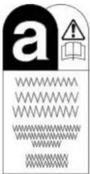
VUJ0000271
-
- Jaguar vehicles and replacement parts which contain asbestos are identified by this symbol. See Asbestos in this subsection.

VUJ0000272
-
- Components or assemblies displaying this symbol give warning that the component contains a corrosive substance. See Acids and Alkalis in this subsection.

VUJ0000273
-
- Vehicles displaying the caution circle with a deleted lighted match symbol, caution against the use of naked lights or flames within the immediate vicinity due to the presence of highly flammable or explosive liquids or vapors. See Fire in this subsection.
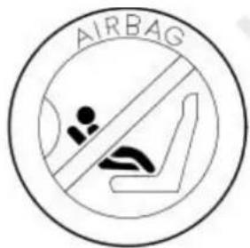
VUJ0002037
-
- All vehicles fitted with the passenger air bag from the factory have a warning sticker attached to the instrument panel, prohibiting the use of rear facing child seats in the front seating position. Failure to follow this instructions may result in personal injury.
White Spirit
See Solvents.
Safety Precautions
- WARNINGS:

Working on the fuel system results in fuel and fuel vapor being present in the atmosphere. Fuel vapor is extremely flammable, hence care must be taken whilst working on the fuel system. Adhere strictly to the following precautions:
- Do not smoke in the work area.
- Display 'no smoking' signs around the area.
- Disconnect the battery before working on the fuel system.
- Do not connect/disconnect electrical circuits, use electrical equipment or other tools or engage in working practices which in any way may result in the production of sparks.
-
Ensure that a CO2 fire extinguisher is close at hand.
-
Ensure that dry sand is available to soak up any fuel spillage.
● Empty fuel using suitable fire proof equipment into an authorized explosion proof container. - Do not empty fuel while working in a workshop or a pit.
- Ensure that working area is well ventilated.
- Ensure that any work on the fuel system is only carried out by experienced and well qualified maintenance personnel.
- Ensure that fume extraction equipment is used where appropriate.

Fume extraction equipment must be in operation when solvents are used e.g. Trichloroethane, white spirit, sbp3, methylene chloride,lorethylene. Do not smoke in the vicinity of volatile degreasing agents.
Whenever possible, use a ramp or pit whilst working beneath a vehicle, in preference to jacking. Position chocks at the wheels as well as applying the parking brake. Never rely on a jack alone to support a vehicle. Use axle stands, or blocks carefully placed at the jacking points, to provide a rigid location. Check that any lifting equipment used has adequate capacity and is fully serviceable. Ensure that a suitable form of fire extinguisher is conveniently located. When using electrical tools and equipment, inspect the power lead for damage and check that it is properly earthed. Disconnect the earth (grounded) terminal of the vehicle battery. Do not disconnect any pipes of the air conditioning refrigeration system unless you are trained and instructed to do so. A refrigerant is used which can cause blindness if allowed to come into contact with the eyes. Ensure that adequate ventilation is provided when volatile degreasing agents are being used.
Adhere strictly to handling and safety instructions given on containers and labels. Keep oils and solvents away from naked flames and other sources of ignition. Do not apply heat in an attempt to free seized nuts or fittings; as well as causing damage to protective coatings, there is a risk of damage from stray heat to electronic equipment and brake lines. Do not leave tools, equipment, spilt oil etc. around the work area. Wear protective overalls and use barrier cream when necessary.
Environmental Protection
In some countries it is illegal to pour used oil onto the ground, down sewers or drains, or into water courses. The burning of used engine oil in small space heaters or boilers is not recommended unless emission control equipment is fitted. Dispose of used oil through authorized waste disposal contractors, to licensed waste disposal sites or to the waste oil reclamation trade. If in doubt, contact the Local Authority for advice on disposal facilities.
General Information - How To Use This Manual
Description and Operation
Copyright Statement
Copyright.© Jaguar Cars Ltd. 1999
All rights reserved. No part of this publication may be reproduced, stored in a retrieval system or transmitted in any form, electronic, mechanical, photocopying, recording or other means, without prior written permission of Jaguar Cars Ltd., Customer Service Department, Browns Lane, Coventry, CV5 9DR, England.
Workshop Manual Organization
This manual covers descriptive, diagnostic (including OBD), and repair aspects to service the vehicle effectively.
The manual is arranged in sections, each section dealing with a specific part of a vehicle system. For example, Section 412-03 covers air conditioning, which is part of the climate control system.
The first digit of the section number indicates the group. There are five groups:
- General Information.
- Chassis.
- Powertrain.
Electrical - Body and Paint.
The second and third digits of the section number indicate the vehicle system.
The last two digits of the section number indicate the part of the system covered by the section.
General Information - Important Safety Instructions
Description and Operation
Safety Notice
Appropriate service methods and correct repair procedures are essential for the safe, reliable operation of all motor vehicles, as well as the safety of the person doing the work. This manual provides general directions for accomplishing service and repair work with tested effective techniques. Following them will help assure reliability.
There are numerous variations in procedures, techniques, tools, and parts for servicing vehicles, as well as in the skill of the person doing the work. This manual cannot possibly anticipate all such variations and provide advice or cautions as to each. Accordingly, anyone who departs from the instructions provided in the manual must first establish that neither personal safety or vehicle integrity is compromised from choices of methods, tools or parts.
General Information - Road/ Roller Testing
Description and Operation
Road or roller testing may be carried out for various reasons and a procedure detailing pre - test checks, through engine starting and stopping, pre - driving checks, on - test checks to final checks on completion of the test is given overleaf.
Unless complete vehicle performance is being checked, the full road test procedure need not be carried out. Instead, those items particularly relevant to the system/s being checked can be extracted.
Pre - Test Checks

WARNING: If the brake system hydraulic fluid level is low, pedal travel is excessive or a hydraulic leak is found, do not attempt to test the vehicle until the reason for the low fluid level, excessive pedal travel or hydraulic leak is found and rectified.
It is suggested that pre - test checks, and functional tests of those systems/circuits which affect the safe and legal operations of the vehicle, such as brakes, lights and steering, should always be carried out before the road or roller test.
- Engine oil level
• Engine coolant level - Tires, for correct pressure, compatible types and tread patterns, and wear within limits.
- There is sufficient fuel in the tank to complete the test.
- All around the engine, transmission and under the vehicle for oil, coolant, hydraulic and fuel leaks. Make a note of any apparent leaks and wipe off the surrounding areas to make it easier to identify the extent of the leak on completion of the test.
Starting the Engine
- NOTE: On initial drive away from cold and within the first 1.5 km (1 mile), do not depress accelerator pedal beyond half travel until the vehicle has attained a minimum speed of 25 km/h (15 miles/h). Never operate at high engine speed or with the accelerator pedal at full travel whilst the engine is cold.
With the ignition switched off, check:
• The handbrake is applied.
• The gear lever is in neutral.
- All instrument gauges (except fuel gauge) read zero.
With the ignition switched on, check:
- Ignition controlled warning lights come on.
- Engine temperature gauge registers a reading compatible with the engine temperature.
- Fuel gauge registers a reading appropriate to the fuel level in the tank.
- The operation of the handbrake warning light and fluid level warning indicator light.
On Road or Roller Test Check:

CAUTION: If road testing, check the brake operation while still travelling at low speed before continuing with the test. If the brakes o one side, or appear to be otherwise faulty, do not continue with the road test until the fault has been found and rectified.
- Clutch pedal operation is not stiff or heavy.
- Initial gear engagement is smooth and there is no evidence of clutch drag.
- Handbrake control operates smoothly and the handbrake releases quickly and completely.
- Clutch takes up the drive smoothly, without slip or judder.
- The engine power output is satisfactory, full power is achieved, acceleration is smooth and pedal operation not stiff or heavy, and engine speed returns to idle correctly.
- There is no excessive or abnormally colored smoke from the engine under normal driving, heavy load or overrun conditions.
- Steering operation, including power steering where fitted, is smooth, accurate, not excessively heavy or with excessive free play or vibration. Does not pull to one side and self centres smoothly after cornering.
- Speedometer, oil pressure warning lamp, coolant temperature gauge and tachometer (where fitted) register the correct readings or operate correctly.
- Switches and controls operate smoothly and positively, warning or indicator lights operate correctly and the direction indicator control self cancels when the steering is returned to the straight ahead position.
● Heating and ventilation systems work correctly and effectively - Brake operation and efficiency.
Brake Testing

WARNING: When brake testing, avoid breathing the smoke or fumes from hot brakes, this may contain asbestos dust which is hazardous to health, see Health and Safety Precautions.
Avoid brake testing on busy roads where it can cause inconvenience or danger to other road users.

CAUTION: Brake testing which includes heavy brake applications should not be carried out with new brake pads/discs or linings/drums the components have bedded - in. New brake friction components will not reach full efficiency until the bedding - in process is lete.
Test the brakes at several speeds within the normal operating range using both light and heavy pedal pressure. Note any tendency to snatch, pull or drag, and any undue delay in application or release.
Allow the vehicle to coast and note any tendency to pull to one side, or evidence that the brakes are binding.
After stopping the vehicle (not immediately after a period of heavy braking), carefully check the brake temperature. A disc which feels hot, or appreciably hotter than the others, indicates that the brake is binding.
After completion of the test, check for:
- Oil, coolant, hydraulic, air and fuel leaks.
- Abnormal temperature of any moving components or assemblies, e.g. wheel hubs, transmission, axle etc., which might indicate overtightness or lack of lubrication.
General Information - Solvents, Sealants and Adhesives
Description and Operation

WARNING: Always handle all solvents, sealers and adhesives with extreme care. Some contain chemicals or give off fumes which can be dangerous to health. Always follow the manufacturers instructions. If in doubt about any substance, particularly a solvent, DO NOT use it.

CAUTION: If in doubt about the suitability of any proprietary solvent or sealer for a particular application, contact the manufacturer of the product for information regarding storage, handling and application.
The Solvents, Sealers and Adhesives subsection refers to some commonly used chemicals and materials, hazards associated with their use, and safety measures to be taken.
Adhesives and Sealers
Highly flammable, flammable, combustible – observe No Smoking policy.
Generally should be stored in No Smoking' areas. Cleanliness and tidiness in use should be observed e.g. disposable paper covering benches; should be dispensed from applicators where possible; containers, including secondary containers, should be labelled appropriately.
Solvent - based Adhesives/ Sealers - See Solvents
Follow manufacturer's instructions.
Water - based Adhesives/ Sealers
Those based on polymer emulsions and rubber latexes may contain small amounts of volatile toxic and harmful chemicals. Skin and eye contact should be avoided and adequate ventilation provided during use.
Hot Melt Adhesives
In the solid state, they are safe. In the molten state they may cause burns and health hazards may arise from the inhalation of toxic fumes.
Use appropriate protective clothing and a thermostatically controlled heater with a thermal cut - out and adequate extraction.
Resin - based Adhesives/ Sealers e.g. Epoxide and Formaldehyde Resin - based
Mixing should be carried out in well ventilated areas, as harmful or toxic volatile chemicals may be released.
Skin contact with uncured resins and hardeners can result in irritation, dermatitis, and absorption of toxic or harmful chemicals through the skin. Splashes can damage the eyes.
Provide adequate ventilation and avoid skin and eye contact.
Anaerobic, Cyanoacrylate (Super - glues) and other Acrylic Adhesives
Many are irritant, sensitizing or harmful to the skin and/or respiratory tract. Some are eye irritants.
Skin and eye contact should be avoided and the manufacturer's instructions followed.
Cyanoacrylate adhesives (super-glues) MUST NOT contact the skin or eyes. If skin or eye tissue is bonded, cover with a clean moist pad and seek immediate medical attention. Do not attempt to pull tissue apart. Use in well ventilated areas as vapors can cause irritation to the nose and eyes.
For two - pack systems see Resin - based and Isocyanate Adhesives/Sealers.
Isocyanate (Polyurethane) Adhesives/ Sealers
See also Resin - based Adhesives
Individuals suffering from asthma or respiratory allergies should not work with or near these materials as sensitivity reactions can occur.
Over exposure is irritating to the eyes and respiratory system. Excessive concentrations may produce effects on the nervous system including drowsiness. In extreme cases, loss of consciousness may result. Long term exposure to vapor concentrations may result in adverse health effects.
Prolonged contact with the skin may lead to skin irritation and, in some cases, dermatitis.
Splashes entering the eye will cause discomfort and possible damage.
Any spraying should preferably be carried out in exhaust ventilated booths removing vapors and spray droplets from the breathing zone.
Wear appropriate gloves, eye and respiratory protection.
General Information - Standard Workshop Practices
Description and Operation
Protecting the Vehicle
Always install covers to protect the fenders before commencing work in the engine compartment. Always install the interior protection kit, wear clean overalls and wash hands or wear gloves before working inside the vehicle. Avoid spilling hydraulic fluid, antifreeze or battery acid on the paintwork. In the event of spillage, wash off with water immediately. Use polythene sheets in the luggage compartment to protect carpets. Always use the recommended service tool, or a satisfactory equivalent, where specified. Protect temporarily exposed screw threads by replacing nuts or installing caps.
Vehicle in Workshop
When working on a vehicle in the workshop always make sure that:
- The parking brake is applied or the wheels are securely chocked to prevent the vehicle moving forwards or backwards
- If the engine is to be run, there is adequate ventilation, or an extraction hose to remove exhaust fumes is installed
- There is adequate room to jack up the vehicle and remove the wheels, if necessary
- Fender covers are always installed if any work is to be carried out in the engine compartment
● The battery is disconnected if working on the engine, underneath the vehicle, or if the vehicle is jacked up

CAUTION: When electric arc welding on a vehicle, always disconnect the generator wiring to prevent the possibility of a surge of current causing damage to the internal components of the generator.
- If using welding equipment on the vehicle, ensure a suitable fire extinguisher is readily available.
Identification Codes - Identification Codes
Description and Operation
Vehicle Identification Number (VIN)
The official VIN is stamped on the right hand side of the boot compartment floor. An additional quick reference and anti forgery identification number is stamped onto a metal plate and fastened to the instrument panel. It is positioned close to the left-hand side of the vehicle and is visible from the outside.
The vehicle identification number is also located on a vehicle certification label or vin plate which is mounted on the bottom of the 'B' Post.

E 44825
| Item Part Number Description | |
| 1 — Quick reference plate | |
| 2 — Certification label (Europe and 3 — Certification label (USA) | Rest of the World) |
| 4 — Official VIN plate |
Vehicle Identification Number (Example)

flowchart
graph TD
    SAJ --> A
    SAJ --> A
    A --> 51
    51 --> R
    R --> ? --> 1
    1 --> C00001
    5 --> 6 --> 7 --> 8 --> 9
    4 --> 3
    3 --> 2
    2 --> 1
VUJ0003165
| Item Part Number Description | |
| 1 — World manufacturer identifier | |
| 2 — Market, air bag specification | |
| 3 — Transmission and steering code | |
| 4 — Body code | |
| 5 — Engine emission system | |
| 6 — Check digit | |
| 7 — Model year | |
| 8 — Assembly plant, model line | |
| 9 — Production sequence number |
World Manufacturer Identifier
VIN Positions 1, 2 and 3
| Codes Manufacturer Make Type | ||
| SAJ Jaguar Cars Limited, England Jaguar Passenger Car |
Market, Air Bag Specification
VIN position 4
| VIN code Description | |
| A Rest of World with twin air bags, side air bags and curtain air bags | |
| K Japan with twin air bags, side air bags and curtain air bags | |
| W | USA with twin air bags, side air bags and curtain air bags |
| X Canada with twin air bags, side air bags and curtain air bags | |
| Y | Mexico with twin air bags, side air bags and curtain air bags |
Transmission, Steering Code
VIN Position 5
| VIN Code | Description |
| A | AWD Automatic LHS |
| B | AWD Manual LHS |
| C | AWD Automatic RHS |
| D | AWD Manual RHS |
| E | FWD Automatic LHS |
| F | FWD Manual LHS |
| G | FWD Automatic RHS |
| H | FWD Manual RHS |
Body Code
VIN Position 6 and 7
| VIN Code | Description |
| 51 | 4-Door, 5 seat saloon high series |
| 52 | 4-Door, 5 seat saloon entry series |
| 53 | 4-Door, 5 seat saloon sport series |
| 54 | 5-Door, 5 seat wagon high series |
| 55 | 5-Door, 5 seat wagon entry series |
| 56 | 5-Door, 5 seat wagon sport series |
Engine Emission System
VIN Position 8
• NOTE: *1 EU. Includes the following markets; Austria, Belgium, Cyprus, Czech Rep, Denmark, Estonia, Finland, France, Germany, Greece, Netherlands, Hungary, Italy, Latvia, Lithuania, Luxembourg, Malta, Poland, Portugal, Rep. of Ireland, Slovenia, Slovakia, Spain (including Canary Islands), Sweden, Bulgaria, Romania and UK.
NOTE: *2 East Europe. Includes the following markets; Croatia and Serbia.
NOTE: *3 Russia. Includes the following markets; Belarus, Kazakhstan, Ukraine and Uzbekistan.
• NOTE: *4 Middle East. Includes the following markets; Abu Dhabi, Bahrain, Dubai, Jordan, Kuwait, Lebanon, Oman, Qatar, Saudi Arabia.
| VINCode | Engine Market | |
| F 2.5L | Argentina, Dominican Rep, Guatemala, *4 Middle East, Panama, Uruguay, Philippines and Taiwan | |
| E 3.0L | ||
| N 2.0L | ||
| M 2.5L | *2 East Europe, Morocco, *3 Russia and Chile | |
| L 3.0L | ||
| S 2.0L | ||
| M 2.5L | *1 EU, Israel, Norway, Switzerland, and Turkey | |
| L 3.0L | ||
| N/A 2.0L | ||
| K 2.5L | Brazil | |
| J 3.0L | ||
| N/A 2.0L | ||
| H 2.5L | Egypt, Syria and South Korea | |
| G 3.0L | ||
| P 2.0L | ||
| M 2.5L | Japan | |
| L 3.0L | ||
| S 2.0L | ||
| N/A 2.5L | USA | |
| A 3.0L | ||
| N/A 2.0L | ||
| N/A 2.5L | Canada | |
| A 3.0L | ||
| N/A 2.0L | ||
| N/A 2.5L | Mexico | |
| L 3.0L | ||
| N/A 2.0L | ||
| F 2.5L | Indonesia, Malaysia, Singapore, Sri Lanka and Thailand | |
| E 3.0L | ||
| N 2.0L | ||
| M 2.5L | Australia, Hong Kong and New Zealand | |
| L 3.0L | ||
| S 2.0L | ||
| H 2.5L | South Africa (includes Trinidad and Tobago) | |
| G 3.0L | ||
| P 2.0L | ||
| M 2.5L | Cyprus, Malta and UK (and Eire) | |
| L 3.0L | ||
| N/A 2.0L | ||
| 1 2.0L | Diesel Argentina, *2 East Europe, *1 EU, Morocco, Norway, Switzerland, Turkey, Uruguay and *3 Russia | |
| 1 2.2L | Diesel Argentina, *2 East Europe, *1 EU (except Belgium), Morocco, Norway, Switzerland, Turkey, Uruguay and *3 Russia | |
| 2 2.2L | Diesel Belgium (110 Kw engine only) | |
| 1 2.0L | Diesel Cyprus, Malaysia, Malta, UK (and Eire), South Africa (includes Trinidad and Tobago) | |
| 1 2.2L | Diesel Cyprus, Malaysia, Malta, UK (and Eire), South Africa (includes Tobago) | |
| 3 2.2L | Diesel + cDPF | *1 EU, Norway, Switzerland, and Turkey |
Check Digit
VIN Position 9
| VIN Code Description | |
| 0 - 9 or X | Calculated in accordance with American standard CFR part 565 |
Model Year
VIN Position 10
| VIN Code Description | |
| 6 | 2006 Model Year |
| 7 | 2007 Model Year |
Assembly Plant and Model Line
VIN Position 11
| VIN Code Description | |
| W | Halewood 3.0L |
| X | Halewood 2.5L |
| Y | Halewood 2.0L |
| 6 | Halewood 2.0L Diesel |
| B | Halewood 2.2L Diesel |
Production Sequence Number
VIN Position 12 through 17
| Sequence Number |
| C00001 - C99999 |
| D00001 - D99999 |
| E00001 - E99999 |
| J00001 - J99999 |
| K00001 - K99999 |
| S00001 - S99999 |
| T00001 - T99999 |
| V00001 - V99999 |
Vehicle Certification Label
The vehicle certification label also contains the 17 character vehicle identification number. This number is used for warranty identification of the vehicle.
Vehicle Certification Number (Europe and Rest of the World)

E36533
| Item Part Number Description | |
| 1 — WVTA number printed here when applicable | |
| 2 — Vehicle identification number | |
| 3 — Gross vehicle weight | |
| 4 — Gross train weight | |
| 5 — Maximum permitted front axle loading | |
| 6 — Maximum permitted rear axle loading | |
| 7 — Date of manufacture | |
| 8 — Interior trim code | |
| 9 — Paint code | |
Vehicle Identification Label (USA)

VUJ0003210
| Item Part Number Description | |
| 1 — Maximum permitted front axle loading | |
| 2 — Date of manufacture | |
| 3 — Gross vehicle weight | |
| 4 — Maximum permitted rear axle loading | |
| 5 — Vehicle identification number | |
| 6 — Type | |
| 7 — Interior trim code | |
| 8 — Paint code |
Vehicle Identification Label (Saudi Arabia and Gulf States)

VUJ0001852
| Item Part Number Description | |
| 1 — Date of manufacture | |
| 2 — Vehicle identification number | |
| 3 — Interior trim code | |
| 4 — Paint code |
Vehicle Identification Label (Canada)

VUJ0001853
| Item Part Number Description | |
| 1 — Maximum permitted front axle loading | |
| 2 — Date of manufacture | |
| 3 — Gross vehicle weight | |
| 4 — Maximum permitted rear axle loading | |
| 5 — Vehicle identification number | |
| 6 — Paint code | |
| 7 — Interior trim code | |
| 8 — Type |
Automatic Transmission Number
The serial number of the automatic transmission unit is displayed on a metal label or bar code (where equipped) attached to the transmission casing.
Manual Transmission Number
The serial number of the manual transmission unit is displayed on a metal label or bar code (where equipped) attached to the transmission casing.
Engine Number (V6)
The engine number is stamped on an engine web on the right hand side of the cylinder block behind the engine mounting..
Engine Number (Diesel)
The engine number is contained on a bar code label on the front cover and is also stamped in the cylinder block casting.
Safety Precautions

CAUTION: The jack provided with the vehicle is intended to be used in an emergency for changing a deflated tire. To avoid damage to vehicle, never use the jack to raise the vehicle for any other purpose. Refer to the Driver Handbook when using the jack supplied with vehicle. Failure to follow these instructions can result in personal injury.
The following safety precautions must be observed when raising the vehicle to carry out service operations:
- Never rely on a jack alone to support a vehicle; use suitable vehicle stands to provide rigid support.
- When working beneath a vehicle, whenever possible, use a vehicle hoist instead of a jack and vehicle stands.
- Make sure that the vehicle is standing on firm, level ground before using a jack.
- Do not rely on the parking brake alone; chock the wheels and put the automatic transmission into PARK if possible.
- Check that any lifting equipment used has adequate capacity for the load being lifted and is in correct working order.
Jacking and Lifting - Lifting
Description and Operation
Lifting Points—Twin-Post Hoist and Floor Jack
- CAUTIONS:

Do not allow the hoist adapters to contact the steering linkage, suspension arms, stabilizer bar, rear subframe stabilizer brackets or compress the lower suspension arm stabilizer bar insulator. Damage to the suspension, exhaust and steering linkage components may if care is not exercised when positioning the hoist adapters of two-post hoists prior to lifting the vehicle.

Never use the differential housing as a lift point. Damage to the differential housing and cover may occur.

When using a floor jack, a cushioned pad must be utilized to avoid body damage.

natural_image
Simple line drawing of two vertical supports with a black circular object on top (no text or symbols)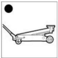
natural_image
Simple line drawing of a manual cart with wheels and a black dot above it (no text or symbols)
natural_image
Technical line drawing of a car's internal components and suspension system (no text or labels)VUJ0003970
Vehicle Support Points

CAUTION: When using vehicle support stands a cushioned pad must be utilized to avoid body damage.
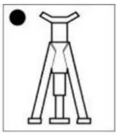
natural_image
Simple line drawing of a tripod-mounted device with a black circular element above it (no text or symbols)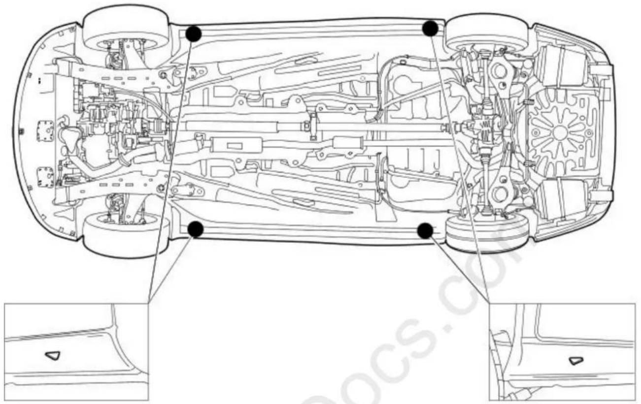
natural_image
Technical line drawing of a car's internal components and dashboard, showing structural layout and mounting points (no text or labels)VUJ0003969
Vehicle Recovery
- NOTE: Prior to vehicle recovery, make sure that the vehicle keys are available and the security system is disarmed.
Vehicle recovery methods are:
- By flat-bed transporter.
- By front suspended tow.
Transporter or Trailer Recovery

natural_image
Line drawing of a flatbed truck with a sedan on top, no text or symbols presentVUJ0001116
When the vehicle is being recovered by transporter or trailer:
- The parking brake must be applied and the wheels chocked.
- The gear selector lever must be in NEUTRAL. Do not select PARK on automatic transmission vehicles, as the parking lock mechanism may be damaged by the forward and backward rocking motion of the vehicle.
- The vehicle must be securely tied down to the transporter or trailer.
Front Suspended Tow

natural_image
Line drawing of a car and a truck, showing front and side views (no text or symbols)VUJ0003968
When the vehicle is being recovered by front suspended tow:

CAUTION: The driveshaft must be disconnected.
- The ignition key must be removed from the ignition switch to lock the steering.
- The front wheels must be correctly positioned in the lifting cradle and securely tied down.
Emergency Towing-Vehicles fitted with manual transmission:

WARNING: If the engine is not running, the steering will become heavy and the force necessary to effectively apply the brakes will be ly increased.

CAUTION: A vehicle with a defective transmission must be towed by front suspended tow.
When the vehicle is being towed with all four wheels on the ground:
- Local regulations for the towing of vehicles must be followed. In some countries the registration number of the towing vehicle and an 'On Tow' sign or warning triangle must be displayed at the rear of the towed vehicle.
• The gear selector lever must be in NEUTRAL. - The ignition switch must be in the RUN position to release the steering lock and make the direction indicators, horn and stop lamps operate.
- A distance of 48 kms (30 miles) must not be exceeded.
- A speed of 48 km/h (30 mph) must not be exceeded.
- The tow rope must be attached to the front towing eye.
Emergency Towing-Vehicles fitted with automatic transmission:

WARNING: If the engine is not running, the steering will become heavy and the force necessary to effectively apply the brakes will be ly increased.

CAUTION: A vehicle with a defective transmission must be towed by front suspended tow.
When the vehicle is being towed with all four wheels on the ground:
- Local regulations for the towing of vehicles must be followed. In some countries the registration number of the towing vehicle and an 'On Tow' sign or warning triangle must be displayed at the rear of the towed vehicle.
- The gear selector lever must be in NEUTRAL.
- The ignition switch must be in the RUN position to release the steering lock and make the direction indicators, horn and stop lamps operate.
- A distance of 0.8 kms (0.5 miles) must not be exceeded.
- A speed of 48 km/h (30 mph) must not be exceeded.
- The tow rope must be attached to the front towing eye.
Noise, Vibration and Harshness - Noise, Vibration and Harshness (NVH)
Description and Operation
Noise, vibration and harshness (NVH) is becoming more important as vehicles become more sophisticated and passenger comfort levels increase. This section is designed to aid in the diagnosis, testing and repair of NVH concerns.
- noise is defined as sounds not associated with the operation of passenger compartment equipment that interface with customer satisfaction.
- vibration is defined as impulses felt by the customer that are not caused by road surface changes.
- harshness is a ride quality issue where the customer feels that the vehicle response to the road surface is sharply transmitted to the customer.
Diagnostic Theory
Diagnosis is more than just following a series of interrelated steps in order to find the solution to the specific condition. It is a way of looking at systems that are not functioning the way they should and finding out why. Also it is knowing how the system should work and whether it is working correctly.
There are basic rules for diagnosis. If these rules are followed, the cause of the condition is usually found the first time through the system.
Know the System
- know how the parts go together.
- know how the system operates as well as its limits and what happens when the system goes wrong.
- sometimes this means checking the system against one that is known to be working correctly.
Know the History of the System
A clue in any one of these areas may save time:
• how old or new is the system?
• what kind of treatment has it had?
- has it been repaired in the past in such a manner that might relate to the present condition?
• what is the repair history?
Know the History of the Condition
• did it start suddenly or appear gradually?
- was it related to some other occurrence such as a collision or previous part renewal?
- know how the condition made itself known; it may be an important clue to the cause.
Know the Probability of Certain Conditions Developing
- Look for the simple rather than the complex.
- For example:
- Electrical conditions usually occur at connections rather than components.
- An engine no-start is more likely to be caused by a loose wire or small adjustment rather than a sheared-off camshaft.
- Know the difference between impossible and improbable. Certain failures in a system can be improbable but still happen.
- New parts are just that, new. It does not mean they are always good functioning parts.
Do Not Cure the Symptom and Leave the Cause
Lowering the pressure in a front tire may correct the condition of a vehicle leaning to one side, but it does not correct the original condition.
Be Positive the Cause is Found
• double check the findings.
• what caused a worn component?
- a loose transmission or engine mount could indicate that other mounts are also loose.
Diagnostic Charts
Charts are a simple way of expressing the relationship between basic logic and a physical system of components. They help discover the cause of a condition in the least time. Diagnostic charts combine many areas of diagnosis into one visual display:
- probability of certain things occurring in a system
• speed of checking certain components or functions before others - simplicity of carrying out certain tests before others
- elimination of checking huge portions of a system by carrying out simple tests
• certainty of narrowing down the search to a small portion before carrying out in-depth testing
The fastest way to find a condition is to work with the tools that are available. This means working with proven diagnostic charts and the correct special equipment for the system.
Noise, Vibration and Harshness - Noise, Vibration and Harshness (NVH)
Diagnosis and Testing
Inspection and Verification
- Verify the customer concern.1.
-
Visually inspect for obvious signs of mechanical damage.2.
-
- If an obvious cause for an observed or reported concern is found, correct the cause (if possible) before proceeding to the next step.
-
- If the concern(s) remains after the inspection, determine the symptom(s) and go to the Symptom Chart.
How To Use This Diagnostic Procedure Section
- Noise, vibration and harshness (NVH) concerns have become more important as vehicles have become more sensitive to these vibrations. This section is designed as an aid to identifying these situations.
- The section provides diagnostic procedures based on symptoms. If the condition occurs at high speed, for instance, the most likely place to start is under High Speed Shake.
- The road test procedure will tell how to sort the conditions into categories and how to tell a vibration from a shake.
- A series of Road Test Quick Checks is provided to make sure that a cause is either pinpointed or eliminated.
- Name the condition, proceed to the appropriate section and locate the correct diagnosis. When the condition is identified, the job is partly done.
- Follow the diagnostic procedure as outlined.
- Quick Checks are described within the step, while more involved tests and adjustments are outlined in General Procedures.
- Always follow each step exactly and make notes to recall important findings later.
Customer Interview
The road test and customer interview (if available) provide information that will help identify the concerns and will provide direction to the correct starting point for diagnosis.
Identify the Condition
NVH usually occurs in a number of areas:
- tires
• engine accessories - suspension
- driveline
• air leakage (wind noise) - squeaks and rattles
• Heating ventilation and air conditioning (HVAC)
• electrical (e.g. motor noise)
It is important, therefore, that an NVH concern be isolated into its specific area(s) as soon as possible. The easiest and quickest way to do this is to carry out the Road Test as outlined.
Noise Diagnostic Procedure
Non-Axle Noise
The five most important sources of non-axle noise are exhaust, tires, roof racks, trim and mouldings, and transmission.
Therefore, make sure that none of the following conditions are the cause of the noise before proceeding with a driveline teardown and diagnosis.
- In certain conditions, the pitch of the exhaust may sound very much like gear noise. At other times, it can be mistaken for a wheel bearing rumble.
- Tires, especially snow tires, can have a high pitched tread whine or roar, similar to gear noise. Radial tires, to some degree, have this characteristic. Also, any non-standard tire with an unusual tread construction may emit a roar or whine type noise.
- Trim and mouldings can also cause whistling or a whining noise.
- Clunk may be a metallic noise heard when the automatic transmission is engaged in reverse or drive, or it may occur when the throttle is applied or released. It is caused by backlash somewhere in the driveline.
- Bearing rumble sounds like marbles being tumbled. This condition is usually caused by a damaged wheel bearing.
Noise Conditions
- Gear noise is typically a howling or whining due to gear damage or incorrect bearing preload. It can occur at various speeds and driving conditions, or it can be continuous.
- Chuckle is a particular rattling noise that sounds like a stick against the spokes of a spinning bicycle wheel. It occurs while decelerating from 64km / h (40 mph) and can usually be heard all the way to a stop. The frequency varies with vehicle speed.
- Knock is very similar to chuckle, though it may be louder and occurs on acceleration or deceleration. The teardown will disclose what has to be corrected.
Check and rule out tires, exhaust and trim items before disassembling the transmission to diagnose and correct gear noise.
The noises described under Road Test usually have specific causes that can be diagnosed by observation as the unit is disassembled. The initial clues are the type of noise heard on the road test and the driving conditions.
Vibration Conditions
- NOTE: New constant velocity (CV) joints should not be installed unless disassembly and inspection revealed unusual wear.
Clicking, popping or grinding noises may be caused by the following:
- cut or damaged drive half shaft joint boots resulting in inadequate or contaminated lube in the outboard or inboard CV joint bearing housings
- loose drive half shaft joint boot clamps
- another component contacting the drive half shaft
- worn, damaged or incorrectly installed wheel bearing, suspension or brake component
Vibration at highway speeds may be caused by the following:
• out-of-balance front or rear wheels
• out-of-round tires
• driveline imbalance
- driveline run-out (alignment)
- NOTE: Drive half shafts are not balanced and do not contribute to rotational vibration disturbances.
Shudder or vibration during acceleration may be caused by the following:
- Excessively worn or damaged outboard or inboard CV joint shaft pilot bearing housing
- Excessively high CV joint operating angles caused by incorrect ride height. Check ride height, verify correct spring rate and check items under Inoperative Conditions
Leakage Conditions
- Inspect the CV joint boots for evidence of cracks, tears or splits.1.
-
- Inspect the underbody for any indication of grease splatter in the vicinity of the front or rear wheel drive half shaft joints and boots. If any grease is present this indicates damage to the half shaft joint boot or boot clamp.
-
- Inspect the inboard CV joint stub shaft pilot bearing housing seal for leakage at the inboard CV joint pilot bearing housing.
Inoperative Conditions
If a CV joint or half shaft pull-out occurs, check the following:
- suspension components for correct location, damage or wear
- bushings for wear
- subframe for damage
-
bent or worn components:
-
stabilizer bar link
- left-hand rear suspension lower arm and bushing
- right-hand rear suspension lower arm and bushing
- rear wheel hub and half shaft
- left-hand front suspension lower arm and bushing
- right-hand front suspension lower arm and bushing
- front wheel hub and half shaft
Road Test
A gear-driven unit will produce a certain amount of noise. Some noise is acceptable and may be audible at certain speeds or under various driving conditions as on a newly paved blacktop road. The slight noise is in no way detrimental and must be considered normal.
The road test and customer interview (if available) provide information needed to identify the condition and give direction to the correct starting point for diagnosis.
-
- Make notes throughout the diagnosis routine. Make sure to write down even the smallest bit of information, because it may turn out to be the most important.
- Do not touch anything until a road test and a thorough visual inspection of the vehicle have been carried out. Leave the tire pressures and vehicle load just where they were when the condition was first observed. Adjusting tire pressures, vehicle load or making other adjustments may reduce the conditions intensity to a point where it cannot be identified clearly. It may also inject something new into the system, preventing correct diagnosis.
-
- Make a visual inspection as part of the preliminary diagnosis routine, writing down anything that does not look right. Note tire pressures, but do not adjust them yet. Note leaking fluids, loose nuts and bolts, or bright spots where components may be rubbing against each other. Check the luggage compartment for unusual loads.
-
- Road test the vehicle and define the condition by reproducing it several times during the road test.
-
- Carry out the Road Test Quick Checks as soon as the condition is reproduced. This will identify the correct diagnostic procedure. Carry out the Road Test Quick Checks more than once to verify they are providing a valid result. Remember, the Road Test Quick Checks may not tell where the concern is, but they will tell where it is not.
Road Test Quick Checks
- 24-80 km/h (15-50 mph): With light acceleration, a moaning noise is heard and possibly a vibration is felt in the front floor pan. It is usually worse at a particular engine speed and at a particular throttle setting during acceleration at that speed. It may also produce a moaning sound, depending on what component is causing it. Refer to Tip-In Moan in the Symptom Chart.
- Acceleration/Deceleration: With slow acceleration and deceleration, a shake is sometimes noticed in the steering wheel/column, seats, front floor pan, front door trim panel or front end sheet metal. It is a low frequency vibration (around 9-15 cycles per second). It may or may not be increased by applying brakes lightly. Refer to Idle Boom/Shake/Vibration in the Symptom Chart.
- High Speed: A vibration is felt in the front floor pan or seats with no visible shake, but with an accompanying sound or rumble, buzz, hum, drone or booming noise. Coast with the clutch pedal depressed or shift control selector lever in neutral and engine idling. If vibration is still evident, it may be related to wheels, tires, front disc brake discs, wheel hubs or front wheel bearings. Refer to High Speed Shake in the Symptom Chart.
-
- Engine rpm Sensitive: A vibration is felt whenever the engine reaches a particular rpm. It will disappear in neutral coasts. The vibration can be duplicated by operating the engine at the problem rpm while the vehicle is stationary. It can be caused by any component, from the accessory drive belt to the clutch or torque converter which turns at engine speed when the vehicle is stopped. Refer to High Speed Shake in the Symptom Chart.
-
Noise and Vibration While Turning: Clicking, popping, or grinding noises may be due to the following:
-
worn, damaged, or incorrectly installed front wheel bearing
- worn, damaged or incorrectly installed half shaft.
Road Conditions
An experienced technician will always establish a route that will be used for all NVH diagnosis road tests. The road selected should be reasonably smooth, level and free of undulations (unless a particular condition needs to be identified). A smooth asphalt road that allows driving over a range of speeds is best. Gravel or bumpy roads are unsuitable because of the additional road noise produced. Once the route is established and consistently used, the road noise variable is eliminated from the test results.
- NOTE: Some concerns may be apparent only on smooth asphalt roads.
If a customer complains of a noise or vibration on a particular road and only on a particular road, the source of the concern may be the road surface. If possible, try to test the vehicle on the same type of road.
Vehicle Preparation
Carry out a thorough visual inspection of the vehicle before carrying out the road test. Note anything which is unusual. Do not repair or adjust any condition until the road test is carried out, unless the vehicle is inoperative or the condition could pose a hazard to the technician.
After verifying the condition has been corrected, make sure all components removed have been installed.
Lift Test
After a road test, it is sometimes useful to do a similar test on a lift.
When carrying out the high-speed shake diagnosis or engine accessory vibration diagnosis on a lift, observe the following precautions:

WARNING: If only one drive wheel is allowed to rotate, speed must be limited to 55 km/h (35 mph) indicated on the speedometer since actual wheel speed will be twice that indicated on the speedometer. Speed exceeding 55 km/h (35 mph) or allowing the drive wheel to hang unsupported could result in tire disintegration, differential failure, constant velocity joint and driveshaft failure, which could cause serious personal injury and extensive vehicle damage. Failure to follow these instructions may result in personal injury.

CAUTION: The suspension should not be allowed to hang free. When the CV joint is run at a very high angle, extra vibration as well as damage to the seals and joints can occur.
The suspension lower arms should be supported as far outboard as possible. To bring the vehicle to its correct ride height, the full weight of the vehicle should be supported in the rear by floor jacks. For additional information, refer to REFER to: Jacking (100-02 Jacking and Lifting, Description and Operation).
- Raise and support the vehicle. For additional information, refer to REFER to: Lifting (100-02 Jacking and Lifting, Description and Operation).
-
Explore the speed range of interest using the Road Test Quick Checks as previously described.
-
- Carry out a coast down in neutral. If the vehicle is free of vibration when operating at a steady indicated speed and behaves very differently in drive and coast, a transmission concern is likely.
Note, however, that a test on the lift may produce different vibrations and noises than a road test because of the effect of the lift. It is not unusual to find vibrations on the lift that were not found in the road test. If the condition found on the road can be duplicated on the lift, carrying out experiments on the lift may save a great deal of time.
Symptom Chart
| Symptom Possible Sources Action | ||
| High-speed shake Wheel end vibration | *Engine/gearbox/transfer box*Driveline | * GO to Pinpoint Test A. |
| Tip-in moan Air cleaner | *Power steering (PS)*Powertrain*Engine mounts*Exhaust system | * GO to Pointpoint Test B. |
| Idle boom/shake/vibration, or shudder Cable(s)/hoses(s)*Engine mounts*Exhaust system*Belt/pulleys | *GO to Pinpoint Test C. | |
| Wheel end vibration analysis Suspension/front or rear wheel drive half shaft and joints*Tires/wheels*Wheel bearings*Front or rear wheel drive half shaft joint boots | *GO to Pinpoint Test D. | |
| Non-axle noise Trim/mouldings | *A/C system*Accessories | * GO to Pinpoint Test E. |
Pinpoint Tests
- NOTE: These Pinpoint Tests are designed to take the technician through a step-by-step diagnosis procedure to determine the cause of a condition. It may not always be necessary to follow the chart to its conclusion. Carry out only the Pinpoint Test steps necessary to correct the condition. Then check operation of the system to make sure the condition is corrected.
After verifying that the condition has been corrected, make sure all components removed have been installed.
TEST CONDITIONS DETAILS/ RESULTS/ ACTIONS
A1: NEUTRAL COAST
1 Carry out the neutral coast test.
| Does the vibration disappear during the neutral coast test?YesCHECK and INSTALL new engine/gearbox/transfer box mounts as necessary. REPEAT Road Test as outlined.NoGO to D1. |
| PINPOINT TEST B : TIP-IN MOAN | |
| TEST CONDITIONS | DETAILS/ RESULTS/ ACTIONS |
| B1: CHECK THE AIR CLEANER | |
| Check the air cleaner.Check the air cleaner, inlet tube, outlet tube, resonators and all other components associated with the air induction system for correct installation and tightness of all connections. | |
| Are the components OK?YesGO to B2.NoCORRECT the condition. REPEAT the Road Test as outlined. | |
| B2: CHECK THE EXHAUST SYSTEM | |
| Carry out the exhaust system neutralizing procedure in this section. | |
| Is the exhaust system OK?YesGO to B3.NoREPAIR as necessary. RESTORE vehicle. REPEAT the Road Test as outlined. | |
| B3: CHECK THE POWER STEERING | |
| Remove the auxiliary drive belt and test for tip-in moan. | |
| Is the tip-in moan OK?YesREPAIR the power steering as necessary. For additional information, refer toREFER to:Power Steering Pump - 2.0L NA V6 - AJV6/2.5L NA V6 - AJV6/3.0L NA V6 - AJ27 (211-02 Power Steering,Removal and Installation).NoCHECK and INSTALL new engine/gearbox/transfer box mounts as necessary. REPEAT Road Test as outlined. | |
| PINPOINT TEST C: IDLE BOOM/ SHAKE/ VIBRATION/ SHUDDER | |
| TEST CONDITIONS | DETAILS/ RESULTS/ ACTIONS |
| C1: CHECK CABLE/ HOSES | |
| Check the engine compartment for any component that may be grounding between the engine and body or chassis.Example: air conditioning (A/C) hoses. | |
| Are the components OK?YesGO to C2.NoCORRECT the condition. REPEAT the Road Test as outlined. | |
| C2: CHECK THE DRIVER AIR BAG MODULE. | |
| Remove the driver air bag module and visually inspect the for correct installation or any touch condition. | |
| Is the driver air bag module OK?YesGO to C3.NoCORRECT the condition. REPEAT the Road Test as outlined. | |
| C3: CHECK THE COOLING RADIATOR | |
| Check the engine cooling radiator mountings and bushings for security and condition. Check the radiator installation for any component that may have a touch condition. | |
| Are the installation and bushings OK?YesGO to C4.NoCORRECT the condition. REPEAT the Road Test as outlined. | |
| C4: CHECK THE EXHAUST SYSTEM | |
| Carry out the exhaust system neutralizing procedure in this section. | |
| Is the exhaust system OK?YesCHECK and INSTALL new engine/gearbox/transfer box mounts as necessary. REPEAT Road Test as outlined.NoREPAIR as necessary. REPEAT Road Test. | |
| PINPOINT TEST D : WHEEL END VIBRATION ANALYSIS | |
| TEST CONDITIONS DETAILS/ RESULTS/ ACTIONS | |
| D1: INSPECT THE TIRES | |
| 1 Inspect the tires.· Raise and support the vehicle. For additional information, refer toREFER to:Lifting(100-02 Jacking and Lifting, Description and Operation).· inspect the tires for:· correct tire size· tire/wheel compatibility· wear or damage· tire beads correctly seatedAre the tires OK?YesGO to D2.NoINSPECT the wheels. For additional information, refer toREFER to: Wheels and Tires (204-04 Wheels and Tires, Diagnosis and Testing). | |
| D2: INSPECT WHEEL BEARINGS | |
| 1 Inspect the wheel bearings. For additional information, refer toREFER to: Wheel Bearing Inspection (204-00 Suspension System - General Information, General Procedures). | |
| Are the wheel bearings OK?YesGO to D3.NoREPAIR as necessary. REPEAT the Road Test as outlined. | |
| D3: INSPECT THE REAR WHEEL DRIVE HALF SHAFT JOINT BOOTS | |
| 1 Inspect the rear wheel drive half shaft joint boots.spin the rear tire by handinspect for evidence of cracks, tears, splits or splattered grease | |
| Are the rear wheel drive half shaft joint boots OK?YesGO to D4.NoREPAIR as necessary. REPEAT the Road Test as outlined. | |
| D4: INSPECT THE FRONT WHEEL DRIVE HALF SHAFT JOINT BOOTS | |
| 1 Inspect the front wheel drive half shaft joint bootsspin the front tire by handinspect for evidence of cracks, tears, splits or splattered grease | |
| Are the front wheel drive half shaft joint boots OK?YesGO to D5.NoREPAIR as necessary. REPEAT the Road Test as outlined. | |
| D5: INSPECT WHEEL AND TIRE RUNOUT | |
| 1 Inspect the wheel and tire runout.Carry out the Wheel and Tire Check procedure. For additional information, refer toREFER to: Wheels and Tires (204-04 Wheels and Tires, Diagnosis and Testing). | |
| Is the wheel and tire runout OK?YesBalance the wheels and tires. Refer to the wheel balance equipment manufacturers instructions.NoREPAIR as necessary. REPEAT the Road Test as outlined. | |
| PINPOINT TEST E : NON-AXLE NOISE | |
| TEST CONDITIONS | DETAILS/ RESULTS/ ACTIONS |
| E1: INSPECT VEHICLE TRIM | |
| Check the grille and trim mouldings to see if they are the source of the noise. | |
| Are the vehicle trim components causing the noise?YesINSTALL new trim or REPAIR as necessary. For additional information, refer toREFER to: Exterior Trim (501-08 Exterior Trim and Ornamentation, Description and Operation).No GO to E2. | |
| E2: CHECK THE A/C SYSTEM FOR NOISE | |
| Check the A/C system components for noise by turning the A/C system on and off. | |
| Is the A/C system causing the noise?YesDiagnose the A/C system. For additional information, refer toREFER to: Climate Control System (412-00 Climate Control System - General Information, Diagnosis and Testing).No GO to E3. | |
| E3: CHECK NON-FACTORY ACCESSORIES | |
| Inspect any accessories for being the source of the noise. Example: grounding body-to-frame, antennas, visors, bug deflectors and fog lights? | |
| Are the accessories the cause of the noise?YesADJUST, REPAIR or INSTALL new accessories or fasteners as required.No Verify the customer concern | |
Noise, Vibration and Harshness - Exhaust System Neutralizing
General Procedures
- Loosen the muffler inlet pipe and resonator pipe to exhaust manifold fasteners at the flanges and the muffler inlet connection.
- Place a stand to support the muffler parallel to the vehicle frame with the muffler pipe bracket free of stress.
- Tighten the muffler connection.
- Position the exhaust pipes to the manifolds and tighten. Make sure that the catalytic converters and heat shields do not contact the frame rails.
- With the complete exhaust system tight (and cooled) the rear hanger insulator should be angled forward, to allow the system to expand rearward when heated during normal running.
Suspension System - General Information -
General Specifications
| Item Specification | |
| Clear Vision | |
| Clear vision (negative value is counterclockwise) 0^ ± 3^ | |
| Ride Height | |
| Front 371 mm ± 15 mm | |
| Rear 370 mm ± 15 mm | |
| Ball Joint Radial Play | |
| Lower ball joint — maximum 0.8 mm | |
Wheel Alignment - Front
| 2001.50 MY onwards VIN - C00344 to Current | ||||
| Item LH RH Split LH-RH | ||||
| Castor Decimal deg | ees 2.25° ± 0.75° 2.25° ± 0.75° 0° | ± 0.75° | ||
| Degrees/minutes | 2° 15' ± 45' | 2° 15' ± 45' | 0° ± 45' | |
| Camber | Decimal degrees | -0.54° ± 0.75° | -0.54° ± 0.75° | 0° ± 0.75° |
| Degrees/minutes | -0° 32' ± 45' | -0° 32' ± 45' | 0° ± 45' | |
| Total toe | Decimal degrees | -0.1° ± 0.20° | ||
| Degrees/minutes | -0° 6' ± 12' | |||
Wheel Alignment - Rear
| 2001.50 MY onwards VIN - C00344 to Current | |||
| Item | LH | RH | |
| Camber | Decimal degrees | - 0.70^ ± 0.75^ | - 0.70^ ± 0.75^ |
| Degrees/minutes | - 0^ 42^ ± 45^ - 0^ 42^ ± 45^ | ||
| Toe | Decimal degrees | 0.125^ ± 0.14^ | 0.125^ ± 0.14^ |
| Degrees/minutes | 0^ 8^ ± 8^ | 0^ 8^ ± 8^ | |
| Total toe | Decimal degrees | 0.25^ ± 0.20^ | |
| Degrees/minutes | 0^ 15^ ± 12^ | ||
| Rear thrust angle | Decimal degrees | 0^ ± 0.14^ | |
| Degrees/minutes | 0^ ± 8^ | ||
- All the above figures are measured at "kerb" height -all fluids at full and a full fuel tank.
• Tires must be inflated to normal pressure
For additional information, refer to: Specifications (204-04 Wheels and Tires, Specifications). - Rear thrust angle = (LH toe - RH toe) ÷ 2
- Ride height is measured from the centre of the wheel to the apex of the wheel arch, through the wheel centre line.
Suspension System - General Information - Wheel Alignment Angles
Description and Operation
Toe is adjustable on the front and rear suspension system. The front toe is adjusted by use of the front tie-rod. The rear toe is adjusted by the use of cam bolts in the lower control arm to the rear crossmember.
Toe
Positive Toe (Toe-In)
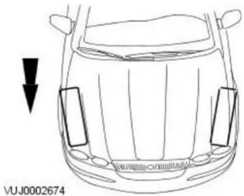
natural_image
Front view line drawing of a car's head with side panels and a downward arrow indicator (no text or symbols)Negative Toe (Toe-Out)

natural_image
Front view line drawing of a car with a downward arrow indicating direction (no text or symbols on the car itself)The vehicle toe setting:
- Affects tire wear and directional stability.
Ride Height
• NOTE: All ride height measurements are carried out with vehicle empty and 9 litres of fuel in the tank (showroom condition).
Front Ride Height Measurement
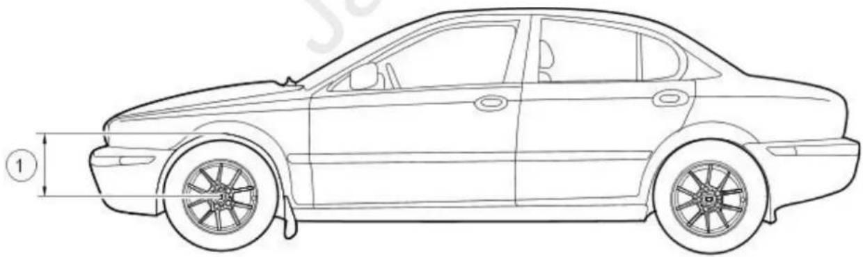
natural_image
Side profile line drawing of a sedan car with visible wheelbase and side panel (no text or symbols)VUJ0002675
Item Description
1 Front ride height measurement
Rear Ride Height Measurement

natural_image
Line drawing of a sedan car side view with no text or symbolsVUJ0002676
| Item Description |
| 1 Rear ride height measurement |
Wheel Track

flowchart
graph TD
    A["Resistor 1"] --> B["Resistor 2"]
    C["Resistor 2"] --> D["Resistor 1"]
    style A fill:#f9f,stroke:#333
    style B fill:#ccf,stroke:#333
    style C fill:#cfc,stroke:#333
    style D fill:#fcc,stroke:#333
A0001102
| Item Description | |
| 1 Front track | |
| 2 Rear track |
Crabbing
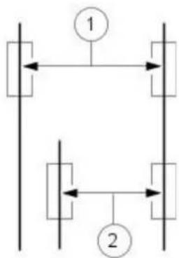
flowchart
graph TD
    A["Resistor"] --> B["Branch 1"]
    C["Resistor"] --> D["Branch 2"]
    B --> E["Output"]
    D --> F["Output"]
A0001103
| Item Description | |
| 1 Front track | |
| 2 Rear track crabbing |
Crabbing is the condition in which the independent rear suspension (IRS) system is not square to the chassis. Heavily crowned roads can give the illusion of crabbing.
Wander
Wander is the tendency of the vehicle to require frequent, random left and right steering wheel corrections to maintain a straight path down a level road.
Shimmy
Shimmy, as observed by the driver, is large, consistent, rotational oscillations of the steering wheel resulting from large, side-to-side (lateral) tire/wheel movements.
Shimmy is usually experienced near 40 miles/hour (64 km/h), and can start or be amplified when the tire contacts pot holes or irregularities in the road surface.
Nibble
Sometimes confused with shimmy, nibble is a condition resulting from tire interaction with various road surfaces and observed by the driver
as small rotational oscillations of the steering wheel.
Poor Returnability of the Steering
Poor returnability of the steering is used to describe the poor return of the steering wheel to center after a turn or the steering correction is completed.
Drift/ Pull
Pull is a tugging sensation, felt by the hands on the steering wheel, that must be overcome to keep the vehicle going straight.
Drift describes what a vehicle with this condition does with hands off the steering wheel.
- A vehicle-related drift/pull, on a flat road, will cause a consistent deviation from the straight-ahead path and require constant steering input in the opposite direction to counteract the effect.
- Drift/pull may be induced by conditions external to the vehicle (i.e., wind, road crown).
Vague On-Center Feel
Vague on-center feel is characterized by little or no build up of turning effort felt in the steering wheel as the wheel is rocked slowly left and right within very small turns around center or straight-ahead (under 20 degrees of steering wheel turn). Efforts may be said to be "flat on center."
- In the diagnosis of a road ability problem, it is important to understand the difference between wander and vague on-center feel.
Suspension System - General Information - Suspension System
Diagnosis and Testing
Inspection and Verification
-
- Verify the customer's concern by carrying out a road test on a smooth road. If any vibrations are apparent, refer to Section 100-04 Noise, Vibration and Harshness.
-
Visually inspect for obvious signs of mechanical damage.2.
Visual Inspection Chart
| Mechanical |
| Damaged tiresWheel bearing(s)Loose or damaged front or rear suspension componentsLoose, damaged or missing suspension retainer(s)Incorrect spring usageDamaged or sagging spring(s)Damaged or leaking shock absorber(s)Damaged or leaking strut(s)Worn or damaged suspension bushing(s)Loose, worn or damaged steering system componentsDamaged axle components |
-
- If an obvious cause for an observed or reported condition is found, correct the cause (if possible) before proceeding to the next step.
-
- If the fault is not visually evident, verify the symptom and refer to the following Symptom Chart.
Symptom Chart
| Symptom Possible Sources Action | |||
| Crabbing Incorrect rear thrust angle. CHECK the rear subframe alignment. For additional information, refer to Section 502-00 Uni-Body, Subframe and Mounting System. | |||
| Drift/Pull Unequal tire pressure. CHECK and ADJUST the tire pressures. INSPECT the tire for excessive wear. For additional information, refer to Section 204-04 Wheels and Tires. | |||
| Front Bottoming or Riding Low | Spring(s). | CHECK the ride height. INSTALL new springs as necessary. For additional information, refer to Section 204-01 Front Suspension. | |
| Incorrect Tire Wear | Incorrect tire pressure (rapid center rib or inner and outer edge wear). | CHECK and ADJUST the tire pressure. INSPECT the tire for excessive wear. For additional information, refer to Section 204-04 Wheels and Tires. | |
| Excessive front or rear toe (rapid inner or outer edge wear). | CHECK and ADJUST the wheel alignment. For additional information, refer to Toe Adjustment-Front or Toe Adjustment-Rear in this section. | ||
| Tires out of balance (tires cupped or dished). | BALANCE the tires. | ||
| Rough Ride | Spring(s). | CHECK and INSTALL new springs as necessary. For additional information, refer to Section 204-01 Front Suspension or Section 204-02 Rear Suspension. | |
| Shock absorber(s). | CHECK and INSTALL new shock absorbers as necessary. For additional information, refer to Section 204-01 Front Suspension or Section 204-02 Rear Suspension. | ||
| Shimmy or Wheel Tramp | Loose wheel nut(s). | CHECK and TIGHTEN the wheel nuts to specification. For additional information, refer to Section 204-04 Wheels and Tires. | |
| Loose front suspension retainers. | CHECK and TIGHTEN the suspension retainers to specification. For additional information, refer to Section 204-01 Front Suspension. | ||
| Front wheel bearing(s). | CHECK the wheel bearings. For additional information, refer to Wheel Bearing Inspection-Front and Rear in this section. | ||
| Wheels/tires. | CHECK the wheels/tires. BALANCE or INSTALL new wheels/tires as necessary. For additional information, refer to Section 204-04 Wheels and Tires. | ||
| Shock absorber(s). | CHECK and INSTALL new shock absorbers as necessary. For additional information, refer to Section 204-01 Front Suspension or Section 204-02 Rear Suspension. | ||
| Spring(s). | CHECK and INSTALL new springs as necessary. For additional information, refer to Section 204-01 Front Suspension or Section 204-02 Rear Suspension. | ||
| Loose, worn or damaged ball joint(s). | CHECK the Ball Joint(s). For additional information, refer to Ball Joint inspection in this section. | ||
| Loose, worn or damaged steering components. | CHECK and INSTALL new components as necessary. For additional information, refer to Section 211-00 Steering System - General Information. | ||
| Front wheel alignment. | CHECK and ADJUST the front wheel alignment. For additional information, refer to Toe Adjustment-Front in this section. | ||
| Poor Returnability of the steering. | Ball joints. CHECK the Ball Joint(s). For additional information, refer to Ball Joint inspection in this section. | ||
| Steering components. CHECK and INSTALL new components as necessary. For additional information, refer to Section 211-00 Steering System - General Information. | |||
| Steering wheel off-center | Unequal front or rear toe settings. | CHECK and ADJUST the wheel alignment. For additional information, refer to Toe Adjustment-Front or Toe Adjustment-Rear in this section. | |
| Steering components. CHECK and INSTALL new components as necessary. For additional information, refer to Section 211-00 Steering System - General Information. | |||
| Sway or roll Overloaded, unevenly or incorrectly loaded vehicle. | NOTIFY the customer of incorrect vehicle loading. | ||
| Loose wheel nut(s). CHECK and TIGHTEN the wheel nut(s) to specification. For additional information, refer to Section 204-04 Wheels and Tires. | |||
| Spring(s). CHECK and INSTALL new springs as necessary. For additional information, refer to Section 204-01 Front Suspension or Section 204-02 Rear Suspension. | |||
| Shock absorber(s). CHECK and INSTALL new shock absorbers as necessary. For additional information, refer to Section 204-01 Front Suspension or Section 204-02 Rear Suspension. | |||
| Loose front stabilizer bar or rear stabilizer bar. | CHECK and TIGHTEN the stabilizer bar to specification. For additional information, refer to Section 204-01 Front Suspension or Section 204-02 Rear Suspension. | ||
| Worn lower suspension arm stabilizer bar bushing. | INSTALL new lower suspension arm stabilizer bar bushing as necessary. For additional information, refer to Section 204-01 Front Suspension or Section 204-02 Rear Suspension. | ||
| Vehicle Leans to One Side | Unevenly loaded or overloaded vehicle. | NOTIFY the customer of incorrect vehicle loading. | |
| Front or rear suspension components. | INSPECT the front and rear suspension systems. REPAIR or INSTALL new suspension components as necessary. For additional information, refer to Section 204-01 Front Suspension or Section 204-02 Rear Suspension. | ||
| Shock absorber(s). CHECK and INSTALL new shock absorbers as necessary. For additional information, refer to Section 204-01 Front Suspension or Section 204-02 Rear Suspension. | |||
| Spring(s). CHECK and INSTALL new springs as necessary. For additional information, refer to Section 204-01 Front Suspension or Section 204-02 Rear Suspension. | |||
| Incorrect ride height. Lateral tilt out of specification. | CHECK the ride height. INSTALL new springs as necessary. For additional information, refer to Section 204-01 Front Suspension or Section 204-02 Rear Suspension. | ||
| Vibration/Noise Tires/Wheels. | CHECK and INSTALL new components as necessary. For additional information, refer to Section 100-04 Noise, Vibration and Harshness. | ||
| Wander Unevenly loaded or overloaded vehicle. | NOTIFY the customer of incorrect vehicle loading. | ||
Component Tests
Ball Joint Inspection
-
- Raise and support the vehicle. For additional information, refer to Section 100-02 Jacking and Lifting.
- Prior to carrying out any inspection of the ball joints, inspect the wheel bearings. For additional information, refer to Wheel Bearing Inspection—Front and Rear.
-
- Position a safety stand beneath the jacking point to test the lower arm.
-
- While an assistant pulls and pushes the top and bottom of the tire, observe the relative movement between the ball joint and the suspension lower arm. Any movement at or exceeding the specification indicates a worn or damaged ball joint. Install a new lower arm as necessary. For additional information, refer to Section 204-01 Front Suspension or Section 204-02 Rear Suspension.
-
- Remove the safety stand.
-
- Lower the vehicle.
Suspension System - General Information - Front Toe Adjustment
General Procedures
- NOTE: The checking and subsequent adjustment of the front toe setting should be carried out on a flat surface and in accordance with the manufactures instructions for the wheel alignment equipment used.

natural_image
Top-down view of a car dashboard with steering wheel and dashboard controls (no text or symbols)- Start the engine and centralize the steering wheel.

natural_image
Technical line drawing of a mechanical assembly with bolts and components (no text or symbols)- Turn the engine off, and hold the steering wheel in the 'straight ahead' position by attaching a rigid link from the steering wheel to the brake pedal.
- Using suitable four wheel alignment equipment, check the toe setting.
- NOTE: Right-hand shown, left-hand similar.
Loosen the tie rod end locknuts.

natural_image
Technical line drawing of a mechanical component with a black arrow indicating a specific part (no text or symbols present)- NOTE: Right-hand shown, left-hand similar.
Reposition the steering gear boot outer clamps.

natural_image
Mechanical assembly diagram showing a rotating shaft and housing with directional arrows indicating motion (no text or symbols)E38483
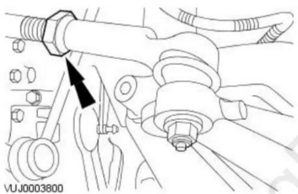
natural_image
Technical line drawing of a mechanical assembly with bolts and components (no text or symbols)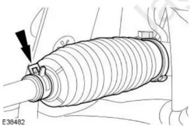
natural_image
Technical line drawing of a mechanical component with a black arrow indicating a specific part (no text or symbols present)- NOTE: Right-hand shown, left-hand similar.
Rotate the tie-rods an equal amount in either a clockwise or a counterclockwise direction to adjust the toe setting.
- NOTE: Right-hand shown, left-hand similar.
Tighten the tie-rod end locknuts.
- Tighten to 40 Nm.
- NOTE: Right-hand shown, left-hand similar.
Reposition the steering gear boot outer clamps.
- Check the toe setting.
Suspension System - General Information - Rear Toe Adjustment
General Procedures
- NOTE: The checking and subsequent adjustment of the rear toe setting should be carried out on a flat surface and in accordance with the manufactures instructions for the wheel alignment equipment used.
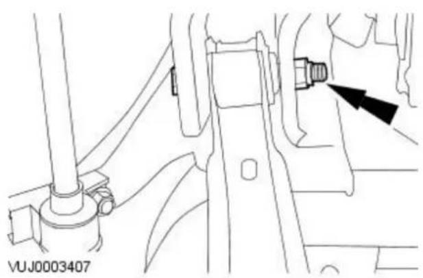
natural_image
Technical line drawing of a mechanical assembly with no visible text or symbols- NOTE: Final tightening of the rear suspension components should be carried out when the vehicle weight is on the road wheels.
Using suitable four wheel alignment equipment, check the toe setting.
- Raise and support the vehicle.
For additional information, refer to Section 100-02 Jacking and Lifting.
- NOTE: Left-hand shown, right-hand similar.
Loosen the rear lower arm cam bolt nuts.

natural_image
Technical line drawing of a mechanical component with no visible text or symbols- Rotate the cam bolts equal amounts, in either a clockwise or a counterclockwise direction, to adjust the toe setting.
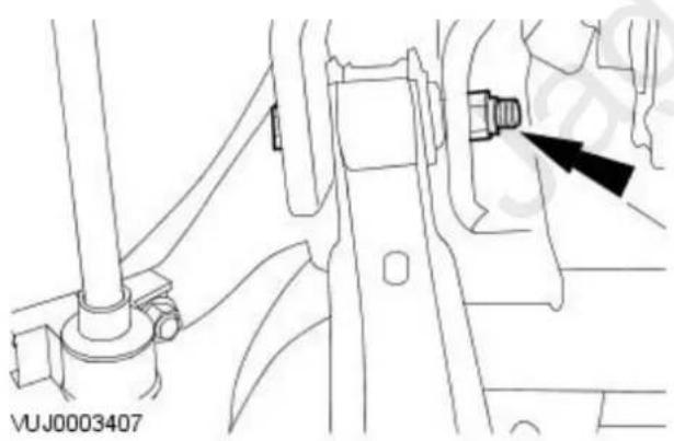
natural_image
Technical line drawing of a mechanical assembly with no visible text or symbols- CAUTION: The final tightening of the suspension components should be carried out with the vehicle on its wheels. Failure to follow this instruction may result in damage to the vehicle.
• NOTE: Left-hand shown, right-hand similar.
Tighten the rear lower arm cam bolt nuts.
- Lower the vehicle.
- Bounce the vehicle to make sure that the suspension is in its normal resting position.

natural_image
Technical line drawing of a mechanical assembly with a black arrow pointing to a component (no text or symbols present)- NOTE: Left-hand shown, right-hand similar.
Tighten the rear lower arm cam bolt nuts.
- Tighten to 115 Nm.
Suspension System - General Information - Wheel Bearing Inspection
General Procedures
- Raise and support the vehicle. For additional information, refer to Section 100-02 Jacking and Lifting.
- NOTE: Make sure the wheel rotates freely and the brake pads are retracted sufficiently to allow movement of the wheel and tire.
Firmly hold the tire at the top and bottom and move the wheel inward and outward while lifting the weight of the wheel and tire off the wheel bearing. - If the wheel and tire is loose on the wheel hub assembly or does not rotate freely, install a new front or rear wheel bearing as necessary. For additional information, refer to Section 204-01 Front Suspension or Section 204-02 Rear Suspension.
Front Suspension -
Torque Specifications
| Description Nm lb-ft lb-in | |||
| Lower arm front retaining bolt A A A | |||
| Lower arm rear retaining nut and bolt A A A | |||
| Lower arm ball joint retaining nut and bolt 83 61 - | |||
| Stabilizer bar to link bar retaining nuts 48 35 - | |||
| Stabilizer bar to subframe retaining bolts 48 35 - | |||
| Strut top mount retaining nuts | 25 18 - | ||
| Subframe front mount retaining bolts | 142 | 105 | - |
| Subframe rear mount retaining bolts | 142 | 105 | - |
| Subframe reinforcement plate retaining bolts (M8) | 35 26 - | ||
| Subframe reinforcement plate retaining bolts (M10) | 70 52 - | ||
| Engine roll restrictor to engine retaining bolt | 80 59 - | ||
| Wheel knuckle pinch bolt | 85 63 - | ||
| Wheel hub retaining nut | 270 | 200 | - |
| Steering column lower retaining bolt | 25 18 - | ||
| A = refer to the procedure for the correct torque sequence | |||
Front Suspension - Front Suspension
Description and Operation

VUJ0003532
| Item Part Number Description | |
| 1 — Front subframe mounting bush | |
| 2 — Stabilizer bar | |
| 3 — Stabilizer link bar | |
| 4 — Suspension strut anti slip fin | |
| 5 — Suspension strut spring | |
| 6 — Wheel knuckle | |
| 7 — Wheel hub bearing | |
| 8 — Wheel hub | |
| 9 — Lower arm | |
| 10 — Ball joint heat shield | |
| 11 — Subframe |
The front suspension consists of two strut and spring assemblies and a subframe, attached to which are the lower arms and the stabilizer bar.
The lower arm is of a pressed steel, fabricated construction which is attached to the subframe by bolts through horizontal and vertical bushings. The lower arm also carries a ball joint that attaches the lower arm to the wheel knuckle. Each wheel knuckle mounts the halfshaft in a double groove ball bearing which is secured on both sides by a snap ring.
The wheel knuckle also mounts to the strut and tie-rod end.
The stabilizer bar consists of a transverse bar with two ball jointed link bars.
The strut and spring assembly is supported from its upper mounting by a rubber insulator fitted to the strut top mount. A coil spring is located between two seats on the strut. A plastic shield is fitted around the piston to prevent dirt and water ingress. A rubber bump stop is also fitted to protect the strut at its fully compressed condition.
As the road wheel rises, the movement is transmitted to the wheel knuckle, then through the ball joints to the lower arms and the strut and spring assembly. The spring absorbs the shock and the damper damps any unwanted spring frequencies, which could lead to an unstable vehicle.
A stabilizer bar is mounted via clamps and bushes to the front subframe and is connected via link bars to each of the strut and spring assemblies.
When cornering, weight is naturally transferred to the outer wheel and there is a natural tendency for the inner wheel to lift. The stabilizer bar helps to minimize this by transferring some of the apparent rise of outer wheel to the inner wheel through the link bars to the strut and spring assemblies. This helps to provide a smoother ride.
Strut and Spring Assembly

| Item Part Number Description | |
| 1 — Spring assembly | |
| 2 — Thrust bearing | |
| 3 — Strut and spring top mount | |
| 4 — Spring isolator | |
| 5 — Bump stop | |
| 6 — Damper piston gaiter | |
| 7 — Damper assembly |
For additional information, refer to Section 204-00 Suspension System - General Information
Front Suspension - Lower Arm
Removal and Installation
| Special Tool(s) | |
 204-192 204-192 | Separator, Ball Joint204-192 (JD-219) |
 | Powertrain Assembly JackHTJ1200-2 |
Removal
All vehicles
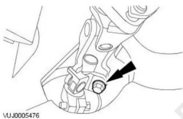
natural_image
Technical line drawing of a mechanical assembly with a black arrow pointing to a component (no text or symbols present)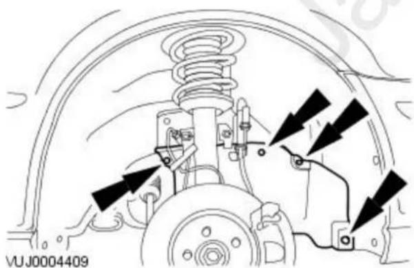
natural_image
Technical diagram of a vehicle suspension system with arrows indicating force directions (no text or symbols present)
natural_image
Technical line drawing of a mechanical assembly with bolts and a bolt head (no text or symbols)- Position the front wheels in a straight ahead position and centralize the steering wheel.
- Lock in position and remove the ignition key.
- Detach the steering column.
-
Remove and discard the steering column lower retaining bolt.
-
Remove the front wheel and tire. For additional information, refer to: Wheel and Tire (204-04 Wheels and Tires, Removal and Installation).
-
Remove the wheel arch liner access cover.
-
Remove both the tie-rod end retaining nuts.
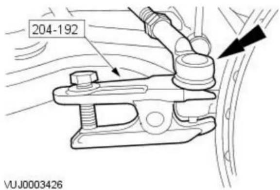
- NOTE: When the tie-rod end is separated from the wheel hub assembly, the ball joint seal should be protected to prevent damage.
Using the special tool, detach the tie-rod end.
Vehicles with high intensity discharge headlamps
- Detach the link rod from the headlamp leveling sensor.
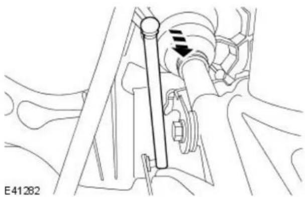
natural_image
Mechanical assembly diagram showing a shaft and gear mechanism (no text or labels)All vehicles
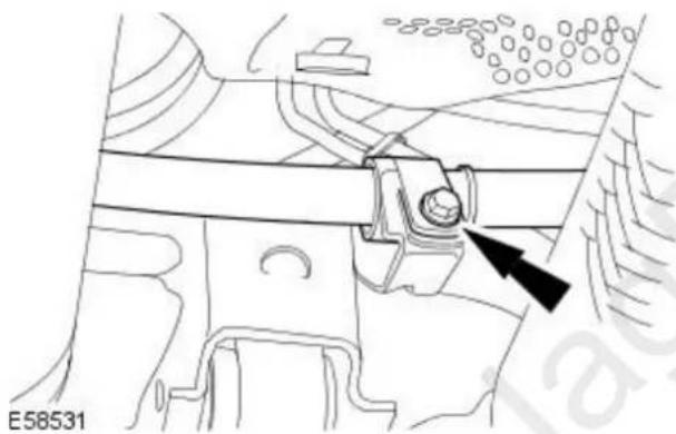
natural_image
Technical diagram of a mechanical assembly with a black arrow pointing to a component (no text or symbols present)- Detach the steering gear supply pipe.
Vehicles with automatic transmission
- Detach the selector lever cable.
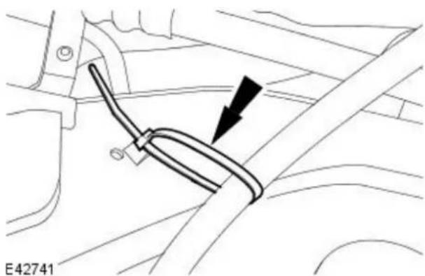
natural_image
Mechanical component diagram showing a cable or clamp assembly with an arrow indicating direction (no text or symbols present)All vehicles

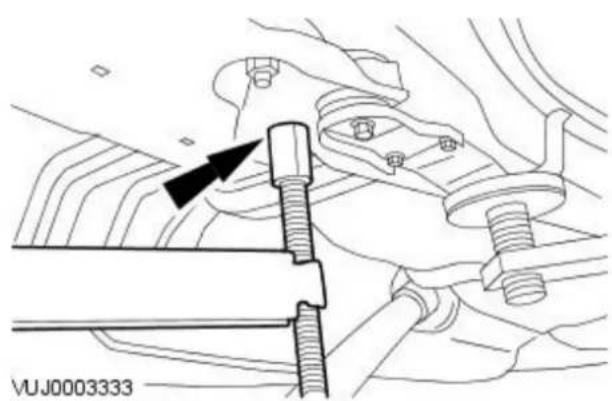
natural_image
Technical line drawing of a mechanical assembly with bolts and tubing (no text or symbols)
natural_image
Technical line drawing of a mechanical component with two black arrows pointing to specific parts (no text or symbols present)
natural_image
Technical line drawing of a mechanical component with a black arrow pointing to a circular feature (no text or symbols present)
natural_image
Technical line drawing of a mechanical assembly with no visible text or symbolsE50621
-
Install the special tool.
-
NOTE: Left-hand shown, right-hand similar.
Position and adjust the special tool rear height adjuster.
- NOTE: Left-hand shown, right-hand similar.
Remove the front subframe reinforcement plate retaining bolts.
- NOTE: Left-hand shown, right-hand similar.
Remove the front subframe rear mount retaining bolts.
- WARNING: Rotate the special tool height adjustment valve slowly. Failure to follow this instruction may result in personal injury.
Using the special tool, lower the front subframe to a maximum of 50 mm (1.97 inches).
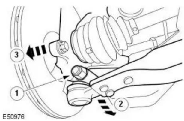

natural_image
Technical line drawing of a mechanical component with a black arrow indicating a specific part (no text or symbols present)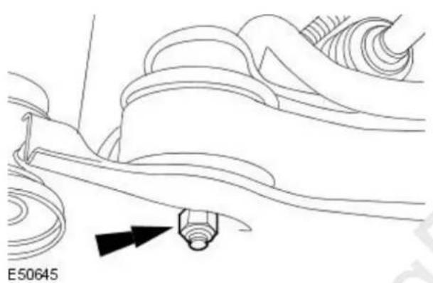
natural_image
Technical line drawing of a mechanical component with no visible text or symbols
natural_image
Mechanical assembly diagram showing suspension components and a directional arrow (no text or labels)
natural_image
Mechanical assembly diagram showing a lever and shaft assembly with a black arrow pointing to a component (no text or symbols present)- CAUTION: To prevent damage to the lower arm bushing, make sure the subframe is lowered before detaching the lower arm ball joint. Failure to follow this instruction may result in damage to the vehicle.
Detach the lower arm from the wheel knuckle.
- Remove the lower arm ball joint retaining nut and bolt.
- Reposition the lower arm.
-
Reposition the wheel knuckle.
-
Remove and discard the lower arm front retaining bolt.
-
Remove and discard the lower arm retaining nut.
-
Reposition the lower arm.
-
Remove the lower arm.
- Remove and discard the lower arm rear retaining bolt.
Installation
All vehicles

natural_image
Mechanical assembly diagram showing a linkage mechanism with no visible text or symbols- Install the lower arm.
• Install a new lower arm rear retaining bolt.
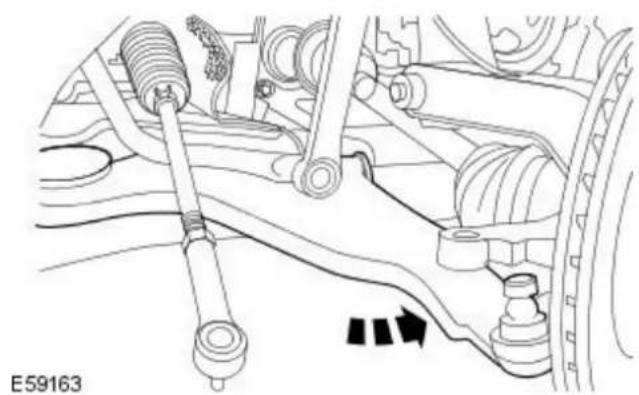
natural_image
Mechanical assembly diagram showing suspension components and a directional arrow (no text or symbols)- Reposition the lower arm.
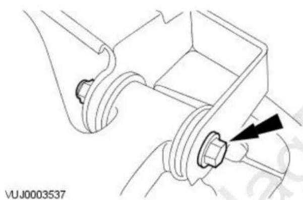
natural_image
Technical line drawing of a mechanical component with a black arrow indicating a specific part (no text or symbols present)- NOTE: Install a new retaining bolt.
Loosely install the lower arm front retaining bolt.
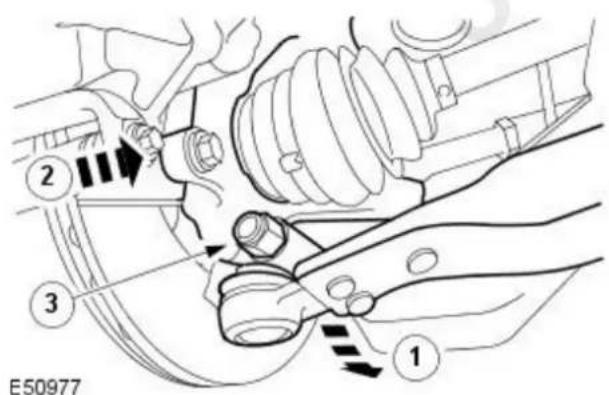
- NOTE: Install a new retaining nut.
Attach the wheel knuckle.
-
Reposition the lower arm.
-
Attach the wheel knuckle.
-
Install the lower arm ball joint retaining nut and bolt.
- Tighten to 83 Nm.


natural_image
Technical line drawing of a mechanical component with a black arrow pointing to a specific part (no text or symbols present)
natural_image
Technical line drawing of a mechanical component with two black arrows pointing to specific parts (no text or symbols present)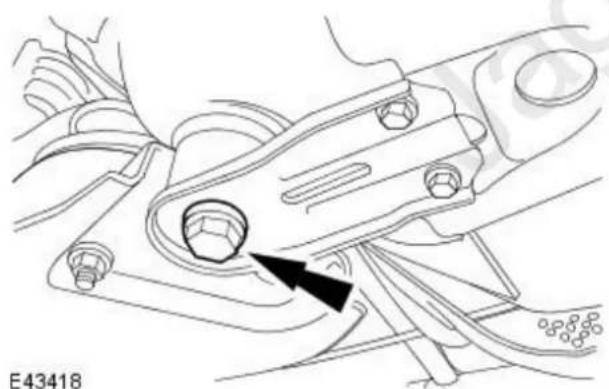
natural_image
Technical line drawing of a mechanical component with a black arrow pointing to a specific part (no text or symbols present)
natural_image
Technical line drawing of a mechanical component with arrows indicating features (no text or symbols present)-
Using the special tool raise the front subframe.
-
NOTE: Left-hand shown, right-hand similar. Loosely install the front subframe rear mount retaining bolts.
-
NOTE: Left-hand shown, right-hand similar. Loosely install the front subframe reinforcement plate retaining bolts.
-
NOTE: Left-hand shown, right-hand similar. Tighten to 142 Nm.
-
NOTE: Left-hand shown, right-hand similar. Tighten the front subframe reinforcement bolts.
-
M8 to 35 Nm.
- M10 to 70 Nm.

- Remove the special tool.
Vehicles with automatic transmission
- Attach the selector lever cable.

natural_image
Mechanical diagram showing a cable or connector inserted into a vehicle's head (no text or symbols visible)All vehicles

natural_image
Technical line drawing of a mechanical component with an arrow pointing to a detail (no text or symbols present)- Attach the steering gear supply pipe.
Vehicles with high intensity discharge headlamps
- Attach the link rod to the headlamp leveling sensor.
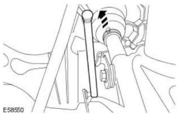
natural_image
Mechanical assembly diagram showing a shaft and gear assembly with no visible text or symbolsAll vehicles

natural_image
Technical line drawing of a mechanical assembly with no visible text or symbols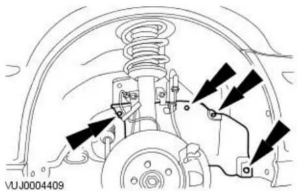
natural_image
Technical diagram of a vehicle suspension system with mounting brackets and springs (no text or labels)

natural_image
Technical line drawing of a mechanical component with a black arrow pointing to a bolt (no text or symbols present)- NOTE: Right-hand shown, left-hand similar.
Attach both the tie-rod ends.
- Tighten to 35 Nm.
-
Install the right-hand wheel arch liner access cover.
-
Install the front wheels and tires.
For additional information, refer to: Wheel and Tire (204-04 Wheels and Tires, Removal and Installation).
-
Lower the vehicle.
-
NOTE: Install a new retaining bolt.
Attach the steering column.
• Install a new steering column lower retaining bolt.
- Tighten to 25 Nm.
- CAUTION: The final tightening of the lower arm front retaining bolt, must be carried out with the vehicle on its wheels. Failure to follow this instruction may result in damage to the vehicle.
- NOTE: Right-hand shown, left-hand similar.
Fully tighten the lower arm front retaining bolt.
• Stage 1: Tighten to 90 Nm.
• Stage 2: Tighten 60 degrees.

natural_image
Technical line drawing of a mechanical component with no visible text or symbols- CAUTION: The final tightening of the lower arm rear retaining nut and bolt, must be carried out with the vehicle on its wheels. Failure to follow this instruction may result in damage to the vehicle.
- NOTE: Right-hand shown, left-hand similar.
Fully tighten the lower arm rear retaining nut and bolt.
• Stage 1: Tighten to 90 Nm.
• Stage 2: Tighten 60 degrees.
- Using the Jaguar approved diagnostic system, configure the steering angle sensor.
Front Suspension - Shock Absorber and Spring Assembly
Removal and Installation
| Special Tool(s) | |
 | Separator, Ball Joint204-192 (JD-219) |
| 204-192 | |
 | Powertrain Assembly JackHTJ1200-2 |
 | Wheel hub puller205-491 |
| 205-491 | |
 | Adapter nuts205-491-01 |
| 20549101 | |
 | Forcing screw204-269 |
 | Knuckle splitter204-159 |
Removal
All vehicles
- Loosen the wheel hub nut.
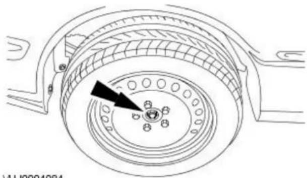
natural_image
Technical line drawing of a mechanical component with concentric rings and a central hub (no text or symbols)VUJ0004084
- Remove the wheel and tire. For additional information, refer to: Wheel and Tire (204-04 Wheels and Tires, Removal and Installation).

natural_image
Technical diagram of a mechanical assembly with no visible text or symbols- Detach the brake hose retaining bracket.

natural_image
Technical line drawing of a mechanical assembly with no visible text or symbols- Detach the stabilizer link bar.

natural_image
Technical diagram of a mechanical component with an arrow pointing to a detail (no text or symbols present)- Disconnect the front wheel speed sensor electrical connector.

natural_image
Mechanical assembly diagram showing gear and valve components with directional arrows (no text or labels)- CAUTION: Secure the brake caliper and anchor plate assembly to one side.
Remove the brake caliper and anchor plate assembly.
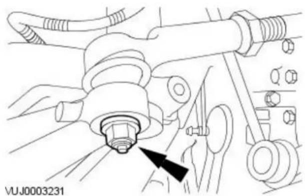
natural_image
Mechanical assembly diagram showing a bolted joint with bolts and a black arrow pointing to a component (no text or symbols present)- Remove the tie-rod end retaining nut.

- NOTE: When the tie-rod end is separated from the wheel hub assembly, the ball joint seal should be protected to prevent damage.
Using the special tool, detach the tie-rod end.
Vehicles with high intensity discharge headlamps
- Detach the link rod from the headlamp leveling sensor.

natural_image
Mechanical assembly diagram showing a shaft and gear mechanism (no text or labels)All vehicles

- Install the special tool.

natural_image
Mechanical assembly diagram showing a bolted joint with a black arrow indicating direction (no text or symbols present)- NOTE: Left-hand shown, right-hand similar.
Position and adjust the special tool rear height adjuster.

natural_image
Technical line drawing of a mechanical component with two black arrows pointing to specific features (no text or symbols present)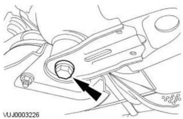
natural_image
Technical line drawing of a mechanical component with a black arrow indicating a specific part (no text or symbols present)
natural_image
Technical line drawing of a mechanical assembly with no visible text or symbols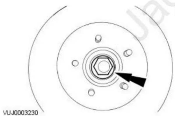
natural_image
Technical diagram of a mechanical component with concentric rings and bolt holes, no text or symbols present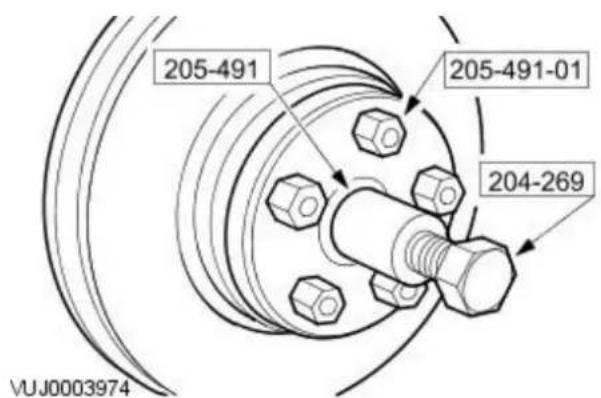
- NOTE: Left-hand shown, right-hand similar.
Remove the front subframe reinforcement plate retaining bolts.
- NOTE: Left-hand shown, right-hand similar.
Remove the front subframe rear mount retaining bolts.
-
Using the special tool, lower the front subframe to a maximum of 30 mm (1.18 inches).
-
Remove and discard the wheel hub nut.
-
Using special tools, detach the halfshaft.


natural_image
Technical line drawing of a mechanical component with a black arrow pointing to a specific part (no text or symbols present)

natural_image
Technical diagram of a mechanical assembly with four bolted components and directional arrows (no text or symbols)- CAUTION: To prevent damage to the lower arm bushing, make sure the subframe is lowered before detaching the lower arm ball joint.
Detach the wheel knuckle.
- Remove the lower arm ball joint retaining nut and bolt.
- Reposition the lower arm.
- Detach the wheel knuckle from the halfshaft.
-
Remove and discard the lower arm ball joint shield.
-
Remove the wheel knuckle pinch bolt.
-
Using the special tool, remove the wheel knuckle.
• Using the special tool, spread the wheel knuckle.
- Remove the wheel knuckle.
- NOTE: Note the orientation of the retaining stud marked with a paint spot.
Remove the strut and spring assembly.
Installation
All vehicles
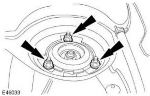
natural_image
Technical diagram of a mechanical assembly with four bolted components and directional arrows indicating motion (no text or symbols)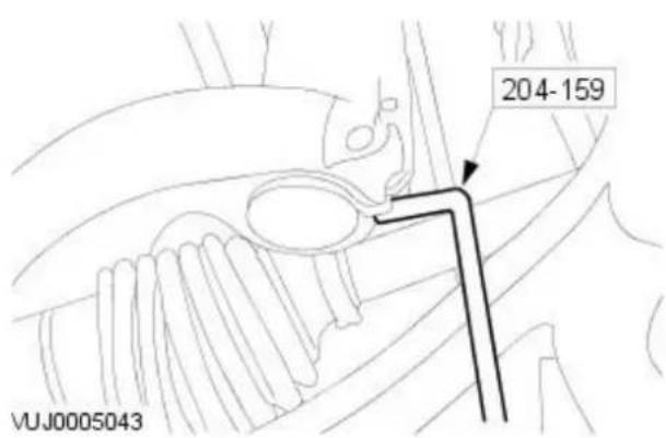
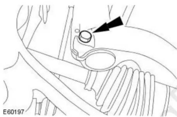
natural_image
Technical line drawing of a mechanical component with an arrow pointing to a circular feature (no text or symbols present)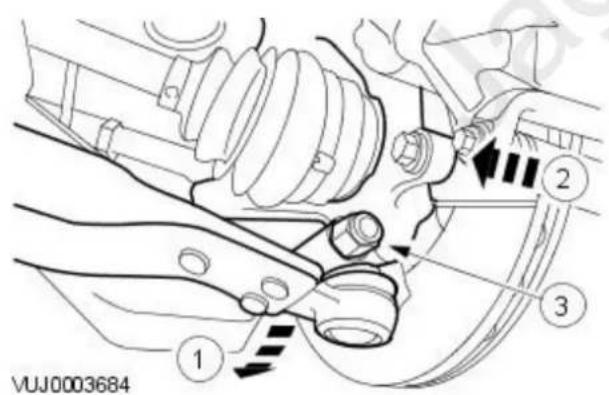

natural_image
Technical diagram of a mechanical component with concentric circles and bolt holes, no text or symbols present- NOTE: Make sure orientation arrow on the strut top rubber mount faces from front to rear of the vehicle.
- NOTE: Make sure the retaining stud marked with a paint spot is correctly orientated.
Install the strut and spring assembly.
- Tighten to 25 Nm.
-
Using the special tool, install the wheel knuckle.
-
Install the wheel knuckle pinch bolt.
- Tighten to 85 Nm.
- NOTE: Install a new retaining nut.
- NOTE: Install a new lower arm ball joint shield.
Attach the wheel knuckle.
- Reposition the lower arm.
- Attach the wheel knuckle to the halfshaft.
- Install the lower arm ball joint retaining nut and bolt.
- Tighten to 83 Nm.
- Loosely install the new wheel hub nut.

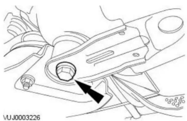
natural_image
Technical line drawing of a mechanical component with a black arrow pointing to a specific part (no text or symbols present)
natural_image
Technical line drawing of a mechanical component with two black arrows pointing to specific parts (no text or symbols present)
natural_image
Technical line drawing of a mechanical assembly with a black arrow pointing to a component (no text or symbols present)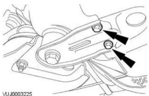
natural_image
Technical line drawing of a mechanical component with two black arrows pointing to specific features (no text or symbols present)-
Using the special tool raise the front subframe.
-
NOTE: Left-hand shown, right-hand similar.
Loosely install the front subframe rear mount retaining bolts.
- NOTE: Left-hand shown, right-hand similar.
Loosely install the front subframe reinforcement plate retaining bolts.
- NOTE: Left-hand shown, right-hand similar.
Tighten the front subframe rear mount retaining bolts.
- Tighten to 142 Nm.
- NOTE: Left-hand shown, right-hand similar.
Tighten the front subframe reinforcement bolts.
- M8 to 35 Nm.
- M10 to 70 Nm.
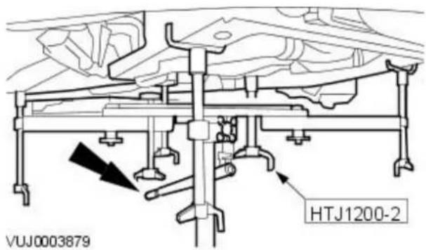
- Remove the special tool.
Vehicles with high intensity discharge headlamps
- Attach the link rod to the headlamp leveling sensor.
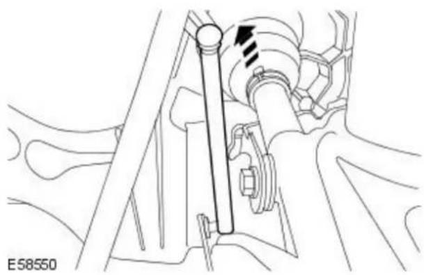
natural_image
Mechanical assembly diagram showing a shaft and gear assembly (no text or labels)All vehicles
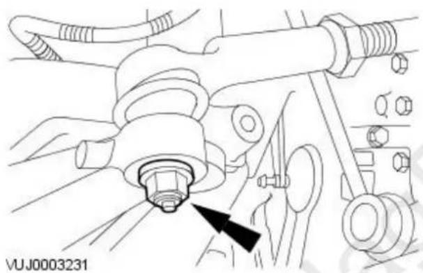
natural_image
Mechanical assembly diagram showing a bolted joint with attached components and a black arrow pointing to a specific component (no text or symbols present)- Attach the tie-rod end.
- Tighten to 35 Nm.

natural_image
Technical diagram of a mechanical assembly with no visible text or symbols- Attach the brake caliper and anchor plate assembly.
- Tighten to 133 Nm.

natural_image
Technical line drawing of a mechanical component with an arrow pointing to a detail (no text or symbols present)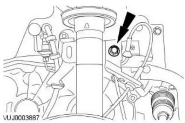
natural_image
Technical line drawing of a mechanical assembly with no visible text or symbols
natural_image
Technical line drawing of a mechanical assembly with no visible text or symbols
natural_image
Technical line drawing of a mechanical component with concentric rings and a black arrow indicating a specific feature (no text or symbols present)-
Connect the front wheel speed sensor electrical connector.
-
Attach the stabilizer link bar.
- Tighten to 48 Nm.
- Attach the brake hose retaining bracket.
- Tighten to 48 Nm.
-
Install the wheel and tire. For additional information, refer to: Wheel and Tire (204-04 Wheels and Tires, Removal and Installation).
-
Tighten the wheel hub nut.
- Tighten to 330 Nm.
Front Suspension - Front Stabilizer Bar
Removal and Installation
Removal

natural_image
Interior view of a car dashboard with steering wheel and dashboard (no text or symbols visible)- NOTE: Make sure the road wheels are in the straight ahead position. Centralize the steering and lock it in position.

natural_image
Mechanical assembly diagram showing a turning tool interacting with a component (no text or symbols visible)- Remove the steering column lower retaining bolt.

natural_image
Technical diagram of a mechanical assembly with arrows indicating motion or force directions (no text or symbols present)- Remove the front subframe. For additional information, refer to Section 502-00 Uni-Body, Subframe and Mounting System.
- Remove the stabilizer bar.
Installation

natural_image
Technical diagram of a mechanical assembly with arrows indicating force or movement (no text or symbols present)- NOTE: Install new stabilizer bar bushes when replacing the stabilizer bar. To install, reverse the removal procedure.
-
Tighten to 48 Nm.
-
Carry out front subframe alignment. For additional information, refer to Section 502-00 Uni-Body, Subframe and Mounting System.
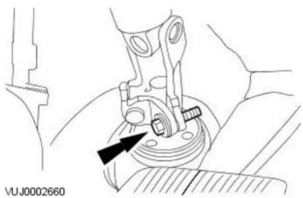
natural_image
Mechanical assembly diagram showing a valve mechanism with a black arrow indicating direction (no text or symbols present)- Tighten to 26 Nm.
Front Suspension - Front Stabilizer Bar Bushing
Removal and Installation
| Special Tool(s) | |
| Powertrain assembly jack HTJ1200-02 | |
Removal
All vehicles

natural_image
Interior view of a car dashboard with steering wheel and dashboard (no text or symbols visible)- Center the steering wheel.
- Lock in position and remove the ignition key.

natural_image
Technical line drawing of a mechanical assembly with a black arrow pointing to a component (no text or symbols present)- Detach the steering column.
- Remove and discard the extension shaft lower retaining bolt.
- Remove the front wheels and tires.
For additional information, refer to: Wheel and Tire (204-04 Wheels and Tires, Removal and Installation).
Vehicles with high intensity discharge headlamps
- Detach the link rod from the headlamp leveling sensor.

natural_image
Mechanical assembly diagram showing a shaft and gear assembly with directional arrows (no text or labels)Vehicles with diesel engine

natural_image
Technical line drawing of a vehicle brake system with mounting bracket and wheel (no text or symbols)-
NOTE: Right-hand shown, left-hand similar. Remove the wheel arch liner access panel.
-
Remove the air deflector. For additional information, refer to: Air Deflector - 2.0L Duratorq-TDCi/2.2L Duratorq-TDCi (110kW/150PS) - Puma (501-02 Front End Body Panels, Removal and Installation).
All vehicles

- Install the special tool.
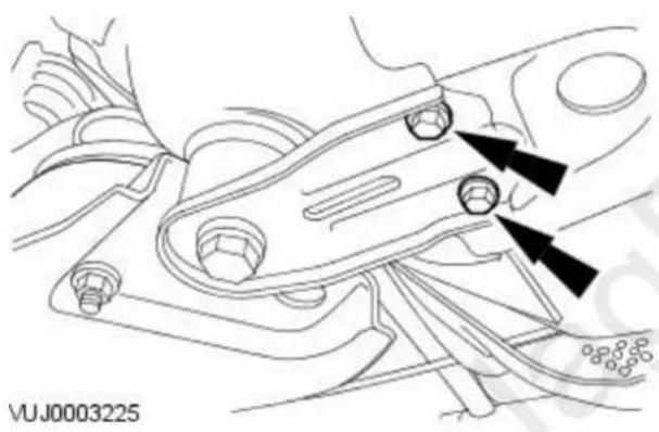
natural_image
Technical line drawing of a mechanical component with two black arrows pointing to specific features (no text or symbols present)- NOTE: Left-hand shown, right-hand similar. Remove the front subframe reinforcement plate retaining bolts.
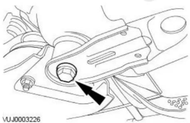
natural_image
Technical line drawing of a mechanical component with a black arrow pointing to a circular feature (no text or symbols)- NOTE: Left-hand shown, right-hand similar. Remove the front subframe rear mount retaining bolts.

natural_image
Technical line drawing of a mechanical assembly with no visible text or symbols
natural_image
Mechanical assembly diagram showing a valve and shaft assembly (no text or symbols)
natural_image
Mechanical assembly diagram showing a valve mechanism with a rotating shaft and housing (no text or symbols)-
WARNING: Rotate the special tool height adjustment valve slowly. Failure to follow this instruction may result in personal injury. Using the special tool, lower the rear of the front subframe to a maximum of 50 mm (1.97 inches).
-
NOTE: Left-hand shown, right-hand similar. Remove the stabilizer bar bush retaining bracket.
-
Remove the retaining bolts.
-
NOTE: Left-hand shown, right-hand similar. Remove the stabilizer bar bush.
Installation
All vehicles
- NOTE: Left-hand shown, right-hand similar. Install the stabilizer bar bush.

natural_image
Mechanical assembly diagram showing a valve mechanism with a black arrow indicating direction (no text or symbols present)
natural_image
Mechanical assembly diagram showing a valve and adjustment mechanism (no text or symbols)

natural_image
Technical line drawing of a mechanical component with a black arrow indicating a specific part (no text or symbols present)
natural_image
Technical line drawing of a mechanical component with arrows pointing to features (no text or symbols)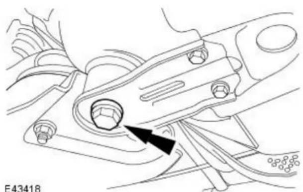
natural_image
Technical line drawing of a mechanical assembly with a black arrow pointing to a component (no text or symbols present)- NOTE: Left-hand shown, right-hand similar. Install the stabilizer bar bush retaining bracket.
-
Tighten the retaining bolts to 48 Nm.
-
Using the special tool, raise the rear of the front subframe.
-
NOTE: Left-hand shown, right-hand similar. Loosely install the front subframe rear mount retaining bolts.
-
NOTE: Left-hand shown, right-hand similar. Loosely install the front subframe reinforcement plate retaining bolts.
-
NOTE: Left-hand shown, right-hand similar. Tighten to 142 Nm.
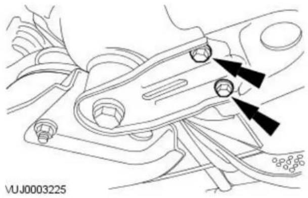
natural_image
Technical line drawing of a mechanical component with two black arrows pointing to specific parts (no text or symbols present)
- Tighten the front subframe reinforcement bolts.
M8 to 35 Nm.
M10 to 70 Nm.
- Remove the special tool.
Vehicles with diesel engine
-
Install the air deflector. For additional information, refer to: Air Deflector - 2.0L Duratorq-TDCi/2.2L Duratorq-TDCi (110kW/150PS) - Puma (501-02 Front End Body Panels, Removal and Installation).
-
NOTE: Right-hand shown, left-hand similar. Install the wheel arch liner access panel.

natural_image
Technical diagram of a vehicle brake system with mounting bracket and wheel assembly (no text or symbols)Vehicles with high intensity discharge headlamps
- Attach the link rod to the headlamp leveling sensor.

natural_image
Mechanical assembly diagram showing a shaft and gear mechanism (no text or labels)All vehicles
- Install the front wheels and tires. For additional information, refer to: Wheel and Tire (204-04 Wheels and Tires, Removal and Installation).
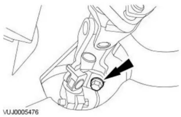
natural_image
Mechanical assembly diagram showing a component with a black arrow pointing to a circular feature (no text or symbols present)- NOTE: Install a new retaining bolt.
Attach the steering column.
• Install a new steering column lower retaining bolt.
- Tighten to 25 Nm.
Front Suspension - Front Wheel Bearing and Wheel Hub
Removal and Installation
| Special Tool(s) | |
 | Front hub carrier support204-310 |
| 204-31C | |
 | Hub flange remover204-116-03 |
| 20411603 | |
 | Bearing remover204-262 |
| 204-262 | |
 | Hub carrier support204-309 |
| 204-309 | |
 | Bearing support204-313 |
| 204-313 | |
 | Bearing guide204-312 |
| 204-312 | |
 | Bearing installer204-311 |
| 204-311 | |
 | Bearing receiver501-063 |
| 501-063 | |
Removal
- Remove wheel knuckle. For additional information refer to, Wheel Knuckle.

- NOTE: When removing the wheel hub from the wheel knuckle the bearing will be destroyed and the bearing inner ring will remain on the wheel hub.
Using special tools, remove the wheel hub.

natural_image
Mechanical assembly diagram showing a shaft and mounting base with a black arrow indicating a specific component (no text or symbols present)- Using a suitable tool, remove the bearing inner ring.
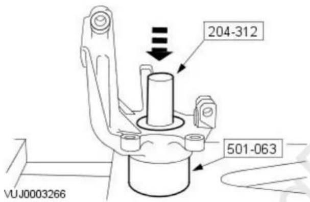
- Using special tools, remove the wheel bearing.
Installation
- NOTE: Insert special tool 204-312 in to 204-309.
Support the wheel knuckle on special tools.
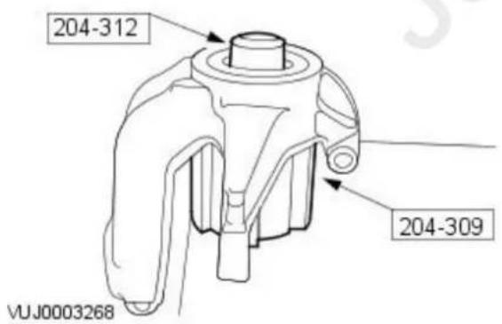

- CAUTION: Make sure wheel bearing is correctly orientated with the colored side facing inboard.
Align the bearing over special tool.
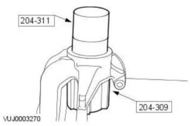
- Using special tools, press bearing into wheel knuckle.
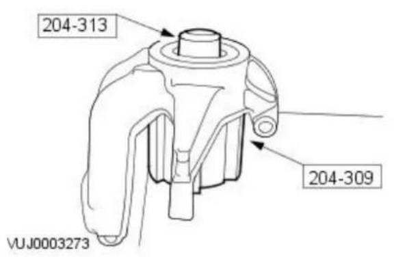
- NOTE: Change special tool 204-312 to 204-313. Align the bearing and wheel knuckle over special tool.
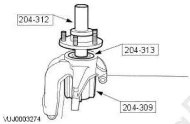
- Slide wheel hub over the guide and align to the bearing.

-
Using special tools install the wheel hub.
-
Install the wheel knuckle. For additional information, refer to Wheel Knuckle.
Front Suspension - Wheel Knuckle
Removal and Installation
| Special Tool(s) | ||
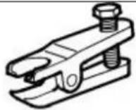 | Ball joint splitter204-192 | |
| 204-192 | ||
 | Wheel hub puller205-491 | |
| 205-491 | ||
 | Adapter nuts205-491-01 | |
| 20549101 | ||
 | Forcing screw204-269 | |
 | Knuckle splitter204-159 | |
| 204-159 | ||
Removal
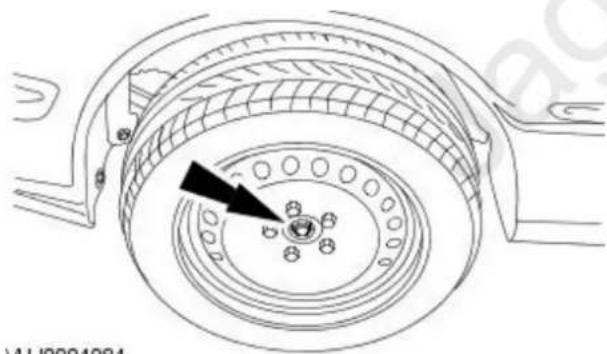
natural_image
Technical line drawing of a mechanical component with concentric rings and a central hub, no visible text or symbols
natural_image
Technical diagram of a mechanical assembly with no visible text or symbols-
Loosen the wheel hub nut.
-
Remove the wheel and tire. For additional information, refer to: Wheel and Tire (204-04 Wheels and Tires, Removal and Installation).
-
CAUTION: Secure the brake caliper anchor plate assembly to one side.
Remove the brake caliper and anchor plate assembly.
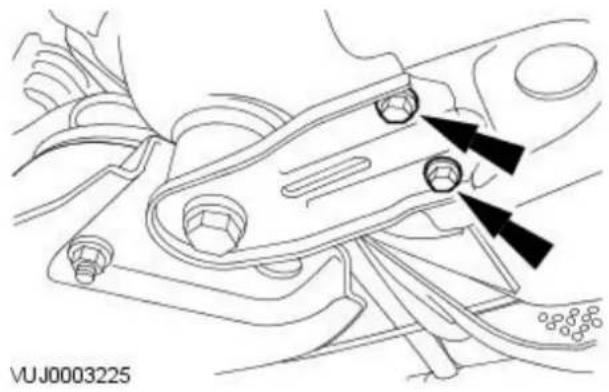
natural_image
Technical line drawing of a mechanical component with two black arrows pointing to specific features (no text or symbols present)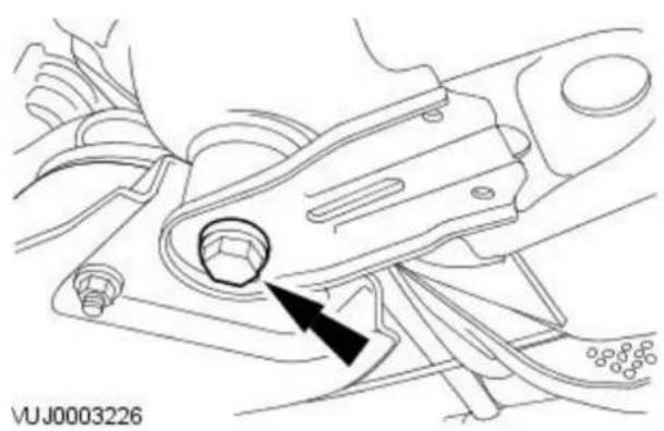
natural_image
Technical line drawing of a mechanical component with a black arrow indicating a specific part (no text or symbols present)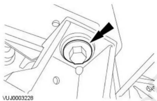
natural_image
Technical line drawing of a mechanical component with a central hexagonal feature and an arrow pointing to it (no text or symbols present)
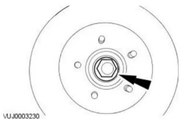
natural_image
Technical diagram of a mechanical component with concentric circles and bolt holes, no text or symbols present- CAUTION: Only one side of the subframe needs to be lowered to detach the lower arm ball joint.
Remove the front subframe reinforcement plate retaining bolts.
-
Loosen the front subframe rear mount retaining bolt.
-
Loosen the front subframe front mount retaining bolt.
-
CAUTION: To prevent damage to the lower arm bushing, make sure the subframe is lowered before detaching the lower arm ball joint.
Detach the wheel knuckle.
- Remove the lower arm ball joint retaining nut and bolt.
- Reposition the lower arm.
-
Detach the wheel knuckle.
-
Remove and discard the wheel hub nut.
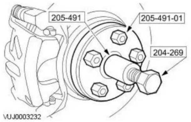
- Using the special tools, detach the halfshaft.

natural_image
Technical line drawing of a mechanical component with a black arrow pointing to a component (no text or symbols present)- Remove the wheel knuckle pinch bolt.

-
Remove the wheel knuckle.
-
Using the special tool, spread the wheel knuckle.
- Remove the wheel knuckle.
Installation
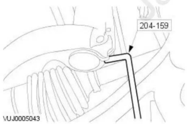
-
Attach the wheel knuckle to the strut and spring assembly.
-
Using the special tool, spread the wheel knuckle.
- Attach the wheel knuckle.
- Tighten to 85 Nm.


natural_image
Technical line drawing of a mechanical component with a central circular feature and an arrow pointing to it (no text or symbols present)
natural_image
Technical line drawing of a mechanical component with a black arrow indicating a specific part (no text or symbols present)
natural_image
Technical line drawing of a mechanical component with two black arrows pointing to specific parts (no text or symbols present)
natural_image
Technical line drawing of a mechanical component with a black arrow pointing to a feature (no text or symbols present)-
Attach the wheel knuckle.
-
Reposition the lower arm.
- Attach the wheel knuckle.
- Attach the lower arm ball joint retaining nut and bolt.
-
Tighten to 83 Nm.
-
Tighten the front subframe front mount retaining bolt.
- Tighten to 142 Nm.
-
Loosely install the subframe rear mount retaining bolt.
-
Tighten the front subframe reinforcement plate retaining bolts.
- Tighten to 35 Nm.
- Tighten to 142 Nm.

natural_image
Technical line drawing of a mechanical assembly with no visible text or symbols- Attach the brake caliper and anchor plate assembly.
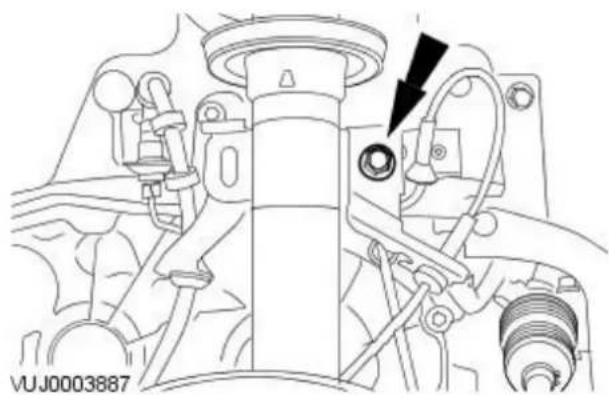
natural_image
Technical line drawing of a mechanical assembly with no visible text or symbols- Attach the stabilizer bar connecting link.
- Tighten to 48 Nm.
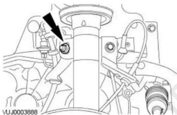
natural_image
Technical line drawing of a mechanical assembly with no visible text or symbols- Attach the brake hose retaining bracket.
- Tighten to 48 Nm.

natural_image
Circular diagram with concentric rings and bolt holes, no text or symbols present-
Install the new wheel hub nut.
-
Install the wheel and tire.
For additional information, refer to: Wheel and Tire (204-04 Wheels and Tires, Removal and Installation).

natural_image
Technical line drawing of a mechanical component with concentric rings and a central hub (no text or symbols)- Tighten the wheel hub nut.
- Tighten to 270 Nm.
- Carry out front subframe alignment procedure.
For additional information, refer to: Underbody Misalignment Check (502-00 Uni-Body, Subframe and Mounting System, General Procedures).
Front Suspension - Shock Absorber and Spring Assembly
Disassembly and Assembly
| Special Tool(s) | |
 | Spring coil compressor204-112 |
| 204-112 | |
| 204-167-01 | Spring adapters204-167-01 |
 | |
| E66191 | |
 | Spring adapters204-112-03 |
| 20411203 | |
Disassembly
- Remove the shock absorber and spring assembly. For additional information, refer to: Shock Absorber and Spring Assembly (204-01 Front Suspension, Removal and Installation).

- WARNING: AS THE SPRING IS UNDER EXTREME TENSION CARE MUST BE TAKEN AT ALL TIMES. FAILURE TO FOLLOW THESE INSTRUCTIONS MAY RESULT IN PERSONAL INJURY.
Using the special tools, compress the spring.

natural_image
Technical line drawing of a mechanical assembly with no visible text or symbols- Loosen the thrust bearing retaining nut.

-
Disassemble the shock absorber and spring assembly.
-
Remove the thrust bearing nut.
- Remove the spacer.
- Remove the top mount.
- Remove the thrust bearing.
- Remove the spring seat.
- Remove the spring.
- Remove the bump stop.
- Remove the gaiter.
- Remove the shock absorber.
Assembly

CAUTION: Make sure the spring locates correctly against the spring seats
- To assemble, reverse the disassembly procedure.
- Tighten to 47 Nm.
Torque Specifications
| Description Nm lb-ft lb-in | |||
| Front lower arm to wheel knuckle retaining bolt 124 91 - | |||
| Front lower arm to subframe retaining bolt 124 91 - | |||
| Rear lower arm to wheel knuckle retaining bolt 124 91 - | |||
| Rear lower arm to subframe retaining bolt 124 91 - | |||
| Upper arm to wheel knuckle retaining bolt 124 91 - | |||
| Upper arm to subframe retaining bolt 124 91 - | |||
| Wheel knuckle to mounting bracket retaining nut* 115 85 - | |||
| Wheel knuckle mounting bracket to body retaining bolts 126 93 - | |||
| Wheel hub to wheel knuckle retaining bolts | 63 | 46 - | |
| Rear halfshaft to wheel hub retaining nut | 270 | 200 | - |
| Damper to wheel knuckle retaining bolt** | 103 | 76 - | |
| Damper to body retaining bolts | 25 | 18 - | |
| Stabilizer bar to subframe retaining bolts*** | 20 | 15 - | |
| Stabilizer bar link arm to rear lower arm retaining nut | 35 | 26 - |
* If you are re-using this fixing on a vehicle built prior to VIN J29473, then tighten to 130 Nm. If you are replacing a fixing on any vehicle, then you must replace both nut and bolt and tighten to 115 Nm.
**If you are re-using this fixing on a vehicle built prior to VIN J24254, then tighten to 130 Nm. If you are replacing a fixing on any vehicle, then you must replace both nut and bolt and tighten to 103 Nm.
*** If you are re-using this fixing on a vehicle built prior to VIN J24259, then tighten to 25 Nm. If you are replacing a fixing on any vehicle, then you must replace both nut and bolt and tighten to 20 Nm.
Rear Suspension - Rear Suspension
Description and Operation

VUJ0002821
| Item Part Number Description | |
| 1 — Wheel knuckle mounting bracket | |
| 2 — Subframe mount bushing | |
| 3 — Upper arm | |
| 4 — Shock absorber | |
| 5 — Spring | |
| 6 — Front lower arm | |
| 7 — Stabilizer bar link | |
| 8 — Subframe | |
| 9 — Stabilizer bar | |
| 10 — Rear lower arm | |
| 11 — Wheel hub | |
| 12 — Wheel knuckle |
The independent rear suspension features an upper arm and front and rear lower arms which attach to the wheel knuckle. The rear lower arm carries the spring and is used to adjust the rear wheel alignment.
Components
The wheel knuckle:
• carries the wheel hub.
• carries the brake caliper assembly.
• carries the Anti-lock brake (ABS) sensor.
The wheel hub:
• carries the brake disc.
• is not a servicable item.
The stabilizer bar link:
• is of a steel construction with a link at each end.
• transmits vertical movements of the rear suspension to the stabilizer bar.
The stabilizer bar:
• is mounted on the subframe.
- is connected to the left-hand and right-hand rear lower arms by the stabilizer bar links.
- is fitted to all models with or without sports suspension.
The upper arm:
- is a one piece steel forging and incorporates rubber bushes with steel inserts at both ends.
• is the upper support for the wheel knuckle.
The front lower arm:
- is of a tubular steel design and incorporates a rubber bush with a steel insert at one end.
- is the front lower support for the wheel knuckle.
The rear lower arm:
- is of a steel design and has cam bolts at the subframe mounting points to adjust wheel alignment.
- is the rear lower support for the wheel knuckle.
• carries the road spring. - is used to adjust the rear wheel alignment
Bushings:
- are a moulded construction with aluminium inserts.
• are incorporated within the subframe to isolate noise and vibrations.
For additional information, refer to Section 204-00 Suspension System - General Information.
Removal

natural_image
Technical line drawing of a mechanical assembly with no visible text or symbols- Raise and support the vehicle. For additional information, refer to: Lifting (100-02 Jacking and Lifting, Description and Operation).
- Detach the damper.

natural_image
Technical diagram of a vehicle engine component with arrows indicating parts (no text or symbols present)- Remove the damper.
Installation
- NOTE: The final tightening of the rear suspension components must be carried out with the vehicle on its wheels.

natural_image
Technical diagram of a vehicle engine compartment with arrows indicating assembly or component alignment (no text or symbols present)- Install the damper.

natural_image
Technical line drawing of a car brake system with no visible text or symbols- Attach the damper.
- NOTE: Carry out final tightening of the rear suspension components.
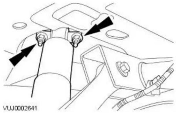
natural_image
Technical line drawing of a mechanical component with arrows indicating assembly or movement (no text or symbols)- Tighten to 25 Nm.
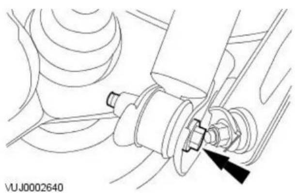
natural_image
Technical line drawing of a mechanical assembly with no visible text or symbols- Tighten to 130 Nm.
Rear Suspension - Front Lower Arm4-Door
Removal and Installation
Removal

natural_image
Technical line drawing of a car suspension bracket with a black arrow pointing to a component (no text or symbols present)- Raise and support the vehicle. For additional information, refer to: Lifting (100-02 Jacking and Lifting, Description and Operation).
-
Detach the front lower arm.
-
Remove the front lower arm.

natural_image
Mechanical assembly diagram showing a lever mechanism with a black arrow pointing to a bolt (no text or symbols present)Installation
- NOTE: The final tightening of the rear suspension components must be carried out with the vehicle on its wheels.

natural_image
Mechanical assembly diagram showing a lever mechanism with a black arrow pointing to a component (no text or symbols present)- Install the front lower arm.
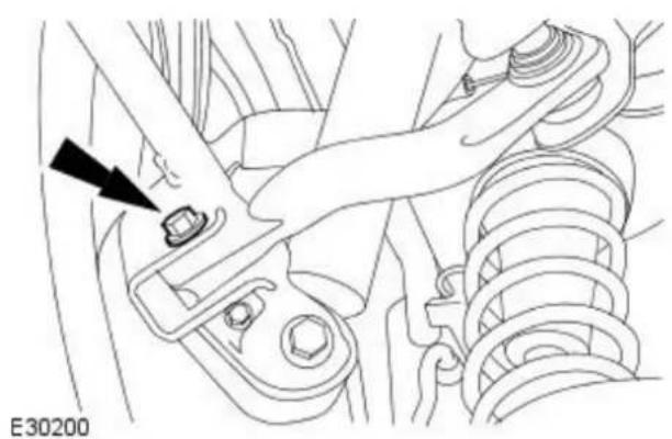
natural_image
Technical line drawing of a mechanical assembly with a black arrow pointing to a component (no text or symbols present)-
Attach the front lower arm.
-
Lower the vehicle.
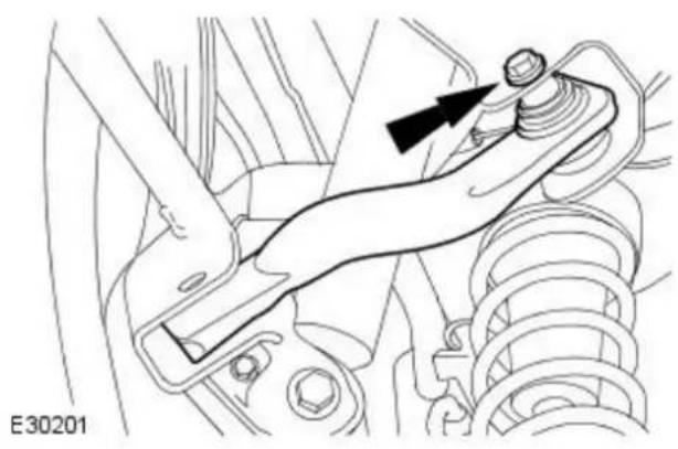
natural_image
Technical line drawing of a mechanical assembly with no visible text or symbols- Tighten to 124 Nm.

natural_image
Technical line drawing of a mechanical assembly with a black arrow pointing to a component (no text or symbols present)- Tighten to 124 Nm.
Rear Suspension - Front Lower Arm Wagon
Removal and Installation
Removal
All vehicles
- Raise and support the vehicle. For additional information, refer to: Lifting (100-02 Jacking and Lifting, Description and Operation).
Vehicles with 2.0L engine

natural_image
Technical line drawing of a mechanical assembly with no visible text or symbols- Remove the fuel tank protection bracket retaining bolt.
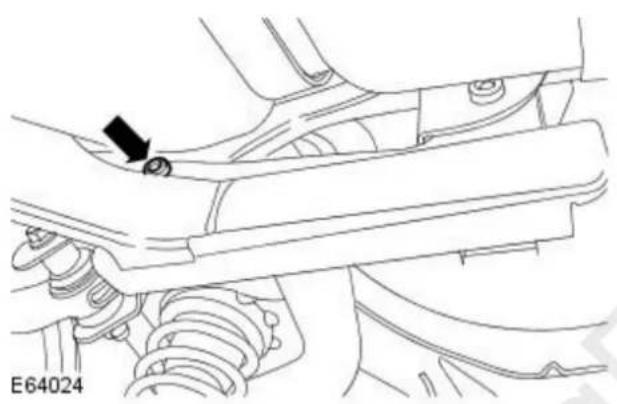
natural_image
Mechanical assembly diagram showing a bracket with mounting holes and spring components (no text or symbols)- Remove the fuel tank protection bracket retaining bolt.
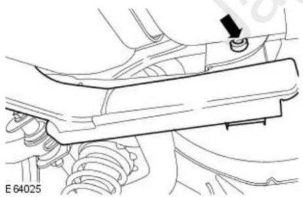
natural_image
Technical line drawing of a mechanical assembly with springs and a lever (no text or symbols)- Reposition the fuel tank protection bracket.
- Loosen the fuel tank protection bracket retaining bolt.
All vehicles
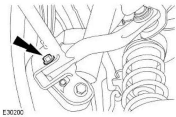
natural_image
Technical diagram of a mechanical assembly with a black arrow pointing to a small component (no text or symbols present)- Detach the front lower arm.
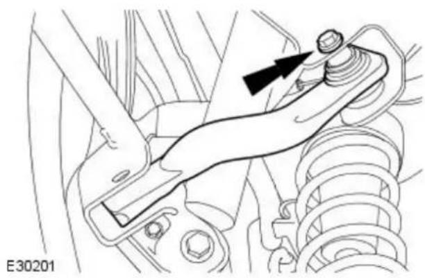
natural_image
Mechanical assembly diagram showing a lever mechanism with a bolt and nut (no text or labels)- Remove the front lower arm.
Installation
All vehicles
- NOTE: The final tightening of the rear suspension components must be carried out with the vehicle on its wheels.

natural_image
Technical line drawing of a mechanical assembly with no visible text or symbols- Install the front lower arm.

natural_image
Technical line drawing of a mechanical assembly with a black arrow pointing to a component (no text or symbols present)- Attach the front lower arm.
Vehicles with 2.0L engine

natural_image
Technical line drawing of a mechanical assembly with no visible text or symbols- Loosely install the fuel tank protection bracket retaining bolt.

natural_image
Technical line drawings of mechanical components, including a lever and shaft assembly (no text or symbols)- Using a suitable torx adaptor, 10 mm combination spanner and 3/8 drive torque wrench, install the fuel tank protection bracket retaining bolt.
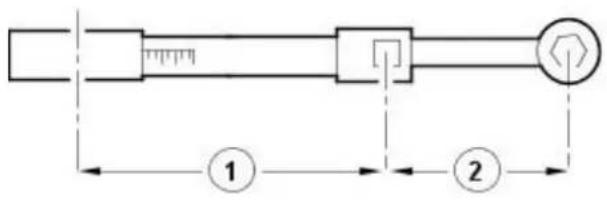
E37107
- Using the torx adaptor, 10 mm combination spanner and 3/8 drive torque wrench, tighten the fuel tank protection bracket retaining bolt.
- To make sure the fuel tank protection bracket retaining bolt is torqued to the correct specification, the following calculation steps must be followed.
-
Step 1. Multiply 25 Nm by the effective length of the torque wrench (1).
-
Step 2. Add the effective length of the special tool (2) to the effective length of the torque wrench (1).
-
Step 3. Divide the total of step 1 by the total of step 2.
-
Step 4. Set the torque wrench to the figure arrived at in step 3.
- Tighten the fuel tank protection bracket retaining bolt to the torque given by the calculation.

natural_image
Technical line drawing of a mechanical suspension system with no visible text or symbols
natural_image
Technical line drawing of a mechanical tool with two components, one showing a wrench and the other a screwdriver (no text or symbols present)E64027

E37107
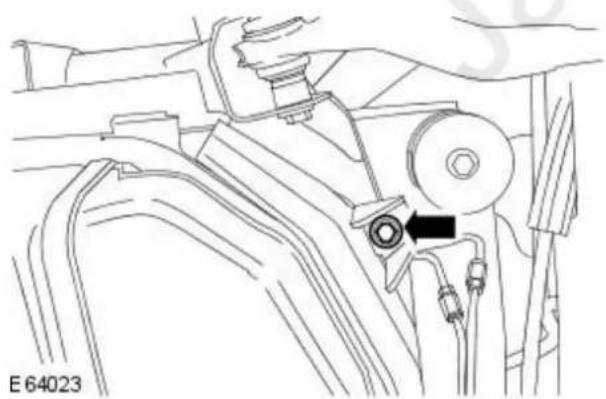
natural_image
Technical line drawing of a mechanical assembly with no visible text or symbols-
Using a suitable torx adaptor, 10 mm combination spanner and 3/8 drive torque wrench, install the fuel tank protection bracket retaining bolt.
-
Using the torx adaptor, 10 mm combination spanner and 3/8 drive torque wrench, tighten the fuel tank protection bracket retaining bolt.
- To make sure the fuel tank protection bracket retaining bolt is torqued to the correct specification, the following calculation steps must be followed.
-
Step 1. Multiply 90 Nm by the effective length of the torque wrench (1).
-
Step 2. Add the effective length of the special tool (2) to the effective length of the torque wrench (1).
-
Step 3. Divide the total of step 1 by the total of step 2.
-
Step 4. Set the torque wrench to the figure arrived at in step 3.
- Tighten the fuel tank protection bracket retaining bolt to the torque given by the calculation.
- Tighten to 63 Nm.
All vehicles
- Lower the vehicle.

natural_image
Technical line drawing of a mechanical assembly with no visible text or symbols- Tighten to 115 Nm.

natural_image
Technical line drawing of a mechanical assembly with a black arrow pointing to a component (no text or symbols present)- Tighten to 115 Nm.
Removal
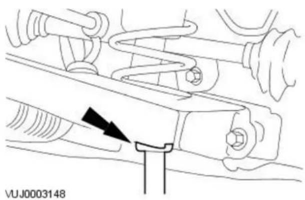
natural_image
Mechanical assembly diagram showing spring and connecting components (no text or symbols)- Remove the rear wheel and tire. For additional information, refer to: Wheel and Tire (204-04 Wheels and Tires, Removal and Installation).
-
Using suitable tie straps, secure the spring to the subframe.
-
CAUTION: Make sure that excessive strain is not placed on the rear lower arm.
Using a suitable transmission jack, support the rear lower arm.
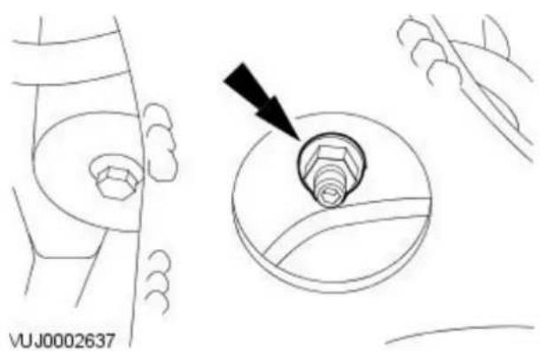
- Detach the stabilizer bar link.
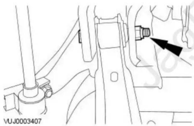
natural_image
Technical line drawing of a mechanical assembly with no visible text or symbols- Detach the rear lower arm.

natural_image
Technical line drawing of a mechanical component with a bolt and arrow indicator (no text or symbols)- CAUTION: Carefully lower the transmission jack.
Remove the rear lower arm.
Installation
- NOTE: The final tightening of the rear suspension components must be carried out with the vehicle on its wheels.

natural_image
Technical line drawing of a mechanical component with a bolt and nut assembly (no text or symbols)- Install the rear lower arm.

natural_image
Technical line drawing of a mechanical assembly with a black arrow pointing to a component (no text or symbols present)- Attach the rear lower arm.

- Attach the stabilizer bar link.

natural_image
Technical line drawing of a mechanical component with a bolt and nut assembly (no text or symbols)-
Install the rear wheel and tire. For additional information, refer to: Wheel and Tire (204-04 Wheels and Tires, Removal and Installation).
-
Tighten to 124 Nm.

natural_image
Technical line drawing of a mechanical assembly with a black arrow pointing to a component (no text or symbols present)
-
Tighten to 124 Nm.
-
Tighten to 35 Nm.
-
Check the wheel alignment and adjust as necessary. For additional information, refer to: Wheel Alignment Angles (204-00 Suspension System - General Information, Description and Operation).
Removal

natural_image
Mechanical assembly diagram showing spring and connecting components (no text or symbols)- Remove the rear wheel and tire. For additional information, refer to: Wheel and Tire (204-04 Wheels and Tires, Removal and Installation).
-
Using suitable tie straps, secure the spring to the subframe.
-
CAUTION: Make sure that excessive strain is not placed on the rear lower arm.
Using a suitable transmission jack, support the rear lower arm.
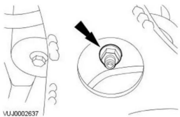
- Detach the stabilizer bar link.

natural_image
Technical line drawing of a mechanical assembly with a bolt and nut (no text or symbols)- Detach the rear lower arm.

natural_image
Technical line drawing of a mechanical assembly with a black arrow pointing to a component (no text or symbols present)- CAUTION: Carefully lower the transmission jack.
Loosen the rear lower arm from the subframe.
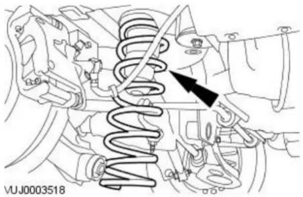
natural_image
Mechanical diagram showing a spring assembly with a black arrow indicating a specific component (no text or symbols present)- Remove the spring.
- Remove the isolator.
Installation
- NOTE: The final tightening of the rear suspension components must be carried out with the vehicle on its wheels.

natural_image
Mechanical diagram showing a spring assembly with a black arrow pointing to a component (no text or symbols present)- Install the spring.
• Install the isolator.

natural_image
Technical line drawing of a mechanical component with a bolt and nut assembly (no text or symbols)- Attach the rear lower arm.
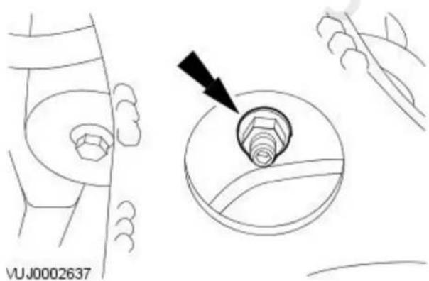
-
Attach the anti roll bar link.
-
Install the wheel rear wheel and tire.
For additional information, refer to: Wheel and Tire (204-04 Wheels and Tires, Removal and Installation).

-
Tighten to 124 Nm.
-
Tighten to 124 Nm.
-
Tighten to 35 Nm.
-
Check the wheel alignment and adjust as necessary. For additional information, refer to: Wheel Alignment Angles (204-00 Suspension System - General Information, Description and Operation).
Rear Suspension - Rear Stabilizer Bar
Removal and Installation
Removal

- Raise and support the vehicle. For additional information, refer to Section 100-02 Jacking and Lifting.
- Detach the stabilizer bar links.
• Right-hand shown, left-hand similar.
- Remove the stabilizer bar.
Installation
- NOTE: The final tightening of the rear suspension components must be carried out with the vehicle on its wheels.

- To install, reverse the removal procedure.
- Tighten to 25 Nm.
- Tighten to 35 Nm.
• Right-hand shown, left-hand similar.
Rear Suspension - Rear Stabilizer Bar Link
Removal and Installation
Removal

- Raise and support the vehicle. For additional information, refer to Section 100-02 Jacking and Lifting.
-
Detach the stabilizer bar link.
-
Remove the stabilizer bar link.
Installation
- NOTE: The final tightening of the rear suspension components must be carried out with the vehicle on its wheels.

natural_image
Technical line drawing of a mechanical assembly with a black arrow indicating a specific component (no text or symbols present)- CAUTION: Make sure rubber boot does not twist while tightening. Tighten to 50 ~Nm .

- To install, reverse the removal procedure.
- Tighten to 35 Nm.
Removal

natural_image
Mechanical assembly diagram showing a valve or connector with a black arrow pointing to a component (no text or symbols present)- Remove the rear wheel and tire. For additional information, refer to: Wheel and Tire (204-04 Wheels and Tires, Removal and Installation).
- Detach the upper arm.

natural_image
Technical diagram of a vehicle's internal components with arrows indicating assembly or movement (no text or symbols present)- Remove the upper arm.
Installation
- NOTE: The final tightening of the rear suspension components must be carried out with the vehicle on its wheels.

- Install the upper arm.
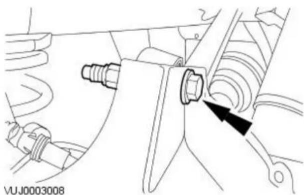
natural_image
Mechanical assembly diagram showing a valve or connector with a black arrow pointing to a component (no text or symbols present)-
Attach the upper arm.
-
Install the wheel and tire assembly. For additional information, refer to: Wheel and Tire (204-04 Wheels and Tires, Removal and Installation).

-
Tighten to 124 Nm .
-
Tighten to 124 Nm.
-
Check the wheel alignment and adjust as necessary. For additional information, refer to: Wheel Alignment Angles (204-00 Suspension System - General Information, Description and Operation).
Rear Suspension - Wheel Hub
Removal and Installation
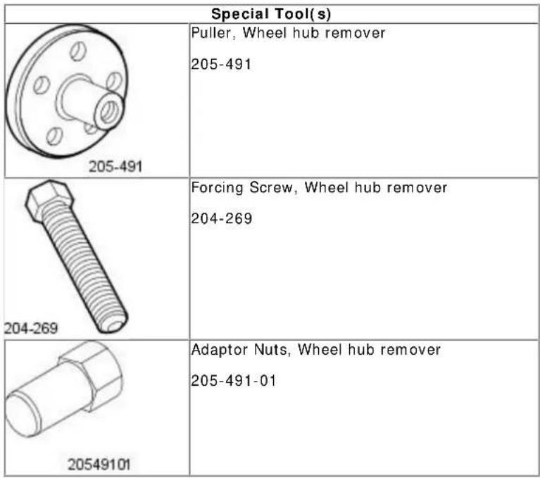 |
Removal
All vehicles
- Remove the rear brake disc. For additional information, refer to: Brake Disc (206-04 Rear Disc Brake, Removal and Installation).
Vehicles with 2.5L or 3.0L engine
- Remove and discard the rear halfshaft retaining nut.

natural_image
Technical diagram of a brake caliper assembly with mounting holes and a black arrow indicating a specific component (no text or symbols present)
natural_image
Technical diagram of a mechanical assembly with four bolts and mounting holes, no text or symbols present- Remove the wheel hub retaining bolts.

- Using the special tools, remove the wheel hub.
Vehicles with 2.0L engine

natural_image
Mechanical assembly diagram showing a connector inserted into a car wheel (no text or symbols visible)- CAUTION: Failure to follow this procedure may result in damage to the anti-lock brake system (ABS) components. Disconnect the anti-lock brake system (ABS) sensor electrical connector.

natural_image
Technical diagram of a mechanical assembly with four bolts and mounting holes (no text or symbols)- Remove the wheel hub.
- Remove the retaining bolts.

natural_image
Mechanical assembly diagram showing a component with arrows pointing to a central component (no text or symbols present)- Remove the (ABS) sensor.
- Remove the retaining bolt.
Installation
All vehicles

natural_image
Technical diagram of a mechanical assembly with four bolts and mounting holes (no text or symbols)- Install the wheel hub.
- Tighten to 63 Nm.
Vehicles with 2.5L or 3.0L engine
- Install a new rear halfshaft retaining nut.
- Tighten to 270 Nm.
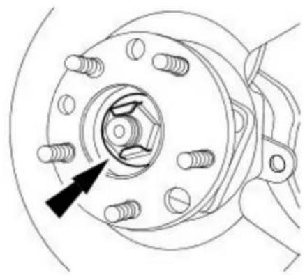
natural_image
Technical line drawing of a mechanical component with bolt holes and a black arrow pointing to a specific feature (no text or symbols present)VUJ0003413
Vehicles with 2.0L engine
- Install the (ABS) sensor.
- Tighten to 7 Nm.

natural_image
Mechanical assembly diagram showing a component with arrows pointing to a central device (no text or symbols present)
natural_image
Mechanical assembly diagram showing a valve inserted into a car wheel (no text or symbols visible)- Reconnect the (ABS) sensor electrical connector.
All vehicles
- Install the rear brake disc. For additional information, refer to: Brake Disc (206-04 Rear Disc Brake, Removal and Installation).
Removal

natural_image
Mechanical assembly diagram showing a clamp securing a car body (no text or symbols present)- Remove the wheel hub. For additional information, refer to: Wheel Hub (204-02, Removal and Installation).
- Remove the anti-lock brake system (ABS) wheel speed sensor wiring harness retaining strap.

- Detach the ABS wheel speed sensor wiring harness.

natural_image
Technical line drawing of a vehicle chassis with a black arrow pointing to a component (no text or symbols present)- Detach the parking brake cable and conduit.
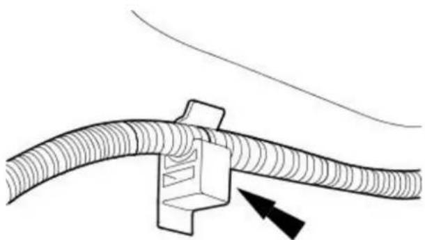
natural_image
Diagram of a cable connector with a directional arrow indicating movement (no text or symbols)- Detach the parking brake cable and conduit.
VUJ0002826

natural_image
Technical line drawing of a mechanical assembly with no visible text or symbols- Detach the damper.

natural_image
Technical line drawing of a mechanical assembly with no visible text or symbols- Detach the upper arm.

natural_image
Mechanical assembly diagram showing a hand fastening a bolt onto a car's seat (no text or symbols)- Detach the front lower arm.

natural_image
Technical line drawing of a mechanical assembly with springs and connectors (no text or symbols)- CAUTION: Make sure that excessive strain is not placed on the lower arm.
Using a suitable transmission jack, support the rear lower arm.

natural_image
Technical diagram of a mechanical assembly with arrows indicating components (no readable text or symbols)- Detach the wheel knuckle mounting bracket.

natural_image
Technical line drawing of a mechanical component with a bolt and nut assembly (no text or symbols)
natural_image
Technical line drawing of a mechanical component with directional arrows indicating movement or force (no text or symbols)- Remove the wheel knuckle.
- Detach the rear lower arm.
- CALITION: Make sure correct position of the mounting bracket is noted before removal.
Remove the wheel knuckle mounting bracket.
Installation
- NOTE: The final tightening of the rear suspension components must be carried out with the vehicle on its wheels.

natural_image
Technical line drawing of a mechanical component with directional arrows indicating movement or force (no text or symbols)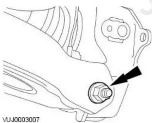
natural_image
Technical line drawing of a mechanical component with a bolt and nut assembly (no text or symbols)- CALATION: Make sure the mounting bracket is installed in the correct position.
Install the wheel knuckle mounting bracket.
- Tighten to 130 Nm.
- Install the wheel knuckle.
- Attach the wheel knuckle mounting bracket.
- Install the front lower arm.
- Attach the upper arm.
- Attach the damper.
- Attach the parking brake cable and conduit.

natural_image
Technical line drawing of a mechanical assembly with no visible text or symbols- Attach the parking brake cable and conduit.

- Attach the ABS wheel speed sensor wiring harness.

natural_image
Mechanical assembly diagram showing a clamp securing a component (no text or symbols visible)- Install a new ABS wheel speed sensor wiring harness retaining strap.
natural_image
Technical line drawing of a mechanical component with a black arrow pointing to a bolt (no text or symbols present)-
Install the wheel hub. For additional information, refer to: Wheel Hub (204-02, Removal and Installation).
-
Tighten to 124 Nm.
natural_image
Mechanical assembly diagram showing a hand fastening a bolt onto a vehicle's seat (no text or symbols visible)
natural_image
Technical line drawing of a mechanical assembly with no visible text or symbols
natural_image
Technical line drawing of a mechanical assembly with no visible text or symbols-
Tighten to 124 Nm.
-
Tighten to 124 Nm.
-
Tighten to 115 Nm.
- Note: If you are re-using this fixing on a vehicle built prior to VIN J29472, then tighten to 130 Nm. If you are replacing a fixing on any vehicle, then you must replace both nut and bolt and tighten to 115 Nm.
- Check the wheel alignment and adjust as necessary. For additional information, refer to: Wheel Alignment Angles (204-00 Suspension System - General Information, Description and Operation).
Rear Suspension - Wheel Knuckle Front Bushing
Removal and Installation
 |
Removal
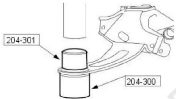
VUJ0003520
- Remove the wheel knuckle. For additional information, refer to For additional information, refer to: Wheel Knuckle (204-02, Removal and Installation)..
- Using the special tools, remove the wheel knuckle front bushing.
Installation

VUJ0003519
-
Using the special tools, install the wheel knuckle front bushing.
-
Install the wheel knuckle. For additional information, refer to For additional information, refer to: Wheel Knuckle (204-02, Removal and Installation)...
Rear Suspension - Wheel Knuckle Rear Bushing
Removal and Installation
 | Special Tool(s) |
| Forcing Screw, Rear Wheel Knuckle Rear Bush204-246 | |
 | Support Cup, Rear Wheel Knuckle Rear Bush204-296 |
| 204-29€ | |
 | Remover, Rear Wheel Knuckle Rear Bush204-298 |
| 204-29€ | |
 | Installer, Rear Wheel Knuckle Rear Bush204-297 |
| 204-297 |
Removal
- Remove the rear wheel and tire.
For additional information, refer to: Wheel and Tire (204-04 Wheels and Tires, Removal and Installation). - Detach the stabilizer bar link.


natural_image
Mechanical assembly diagram showing spring and connecting rod components (no text or symbols)- CAUTION: Make sure that excessive strain is not placed on the lower arm.
Using a suitable transmission stand, support the rear lower arm.

natural_image
Technical line drawing of a mechanical component with a bolt and nut assembly (no text or symbols)- Detach the rear lower arm.

- CAUTION: Carefully lower the transmission jack.
Using the special tools, remove the wheel knuckle rear bushing.
Installation
- NOTE: The final tightening of the rear suspension components must be carried out with the vehicle on its wheels.
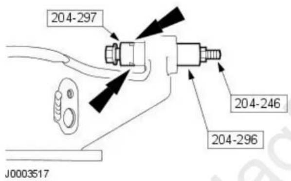
- Using the special tools, install the wheel knuckle rear bushing.
- Align the bushing horizontally.

natural_image
Technical line drawing of a mechanical assembly with a bolt and nut (no text or symbols)- CAUTION: Carefully raise the transmission jack.
Attach the rear lower arm.

- Attach the stabilizer bar link.

natural_image
Technical line drawing of a mechanical component with a bolt and arrow indicating a detail (no text or symbols present)- Install the rear wheel and tire.
For additional information, refer to: Wheel and Tire (204-04 Wheels and Tires, Removal and Installation).
- Tighten to 124 Nm.

-
Tighten to 35 Nm.
-
Check the wheel alignment and adjust as necessary.
For additional information, refer to: Wheel Alignment Angles (204-00
Suspension System - General Information, Description and Operation).
Tire Pressures
| Wheel Size Tire | Size Tire Manufacturer Rim Engine | Comfort Normal | ||||||
| Front Rear | Front Rear | |||||||
| 16" 205/55 R16 | 91 V | Pirelli P6000 6.5Jx16 | 2.0L 2.07 | bar (30 | bf/in2) | 2.07 bar (30 lbf/in2) | 2.41 bar (35 lbf/in2) | 2.21 bar (32 lbf/in2) |
| 2.5L and 3.0L 2 | 21 bar (32 lbf/in2) | 2.21 bar (32 lbf/in2) | 2.62 bar (38 lbf/in2) | 2.41 bar (35 lbf/in2) | ||||
| 2.0L and 2.2L Diesel | 2.21 bar (32 lbf/in2) | 2.07 bar (30 lbf/in2) | 2.41 bar (35 lbf/in2) | 2.21 bar (32 lbf/in2) | ||||
| 205/55 R16 91 H | Continental CH95 6.5 | Jx162.5 | L and 3.0L 2.21 | bar (32 lbf/in2) | 2.21 bar (32 lbf/in2) | 2.62 bar (38 lbf/in2) | 2.41 bar (35 lbf/in2) | |
| 17" 225/45 R17 | 91 Y | Pirelli P Zero | 7Jx17 | 2.5L and 3.0L 2 | 07 bar (30 lbf/in2) | 2.07 bar (30 lbf/in2) | 2.62 bar (38 lbf/in2) | 2.41 bar (35 lbf/in2) |
| 2.0L and 2.2L Diesel | 2.21 bar (32 lbf/in2) | 2.07 bar (30 lbf/in2) | 2.48 bar (36 lbf/in2) | 2.34 bar (34 lbf/in2) | ||||
| 225/45 R17 91 H | Continental CH95 7Jx | 17 2.5 | L and 3.0L 2.07 | bar (30 lbf/in2) | 2.07 bar (30 lbf/in2) | 2.62 bar (38 lbf/in2) | 2.41 bar (35 lbf/in2) | |
| 225/45 R17 94 W | Continental SportContact | 7Jx17 | 2.5L and 3.0L 2 | 34 bar (34 lbf/in2) | 2.34 bar (34 lbf/in2) | 2.62 bar (38 lbf/in2) | 2.41 bar (35 lbf/in2) | |
| 2.0L and 2.2L Diesel | 2.34 bar (34 lbf/in2) | 2.34 bar (34 lbf/in2) | 2.62 bar (38 lbf/in2) | 2.41 bar (35 lbf/in2) | ||||
| 205/50 R17 93 Y | Pirelli P Zero Rosso | 7Jx17 | 2.0L 2.34 bar (3 | 4 lbf/in2) | 2.34 bar (34 lbf/in2) | 2.48 bar (36 lbf/in2) | 2.34 bar (34 lbf/in2) | |
| 18" 225/40 R18 | 92 Y | Pirelli P Zero Nero | 7.5x18 | 2.0L 2.34 bar (3 | 4 lbf/in2) | 2.21 bar (32 lbf/in2) | 2.62 bar (38 lbf/in2) | 2.41 bar (35 lbf/in2) |
| 2.5L and 3.0L 2 | 48 bar (36 lbf/in2) | 2.34 bar (34 lbf/in2) | 2.76 bar (40 lbf/in2) | 2.41 bar (35 lbf/in2) | ||||
| 2.0L and 2.2L Diesel | 2.34 bar (34 lbf/in2) | 2.21 bar (32 lbf/in2) | 2.62 bar (38 lbf/in2) | 2.41 bar (35 lbf/in2) | ||||
| 16" (temporary use spare wheel) | T125/85 R16 99 M | Pirelli | 4Jx16 | All Variants | 4.14 bar (60 ibf/in2) | |||
Torque Specifications
| Description | Nm | lb-ft | lb-in |
| Wheel nuts - Vehicles with steel wheels | 80 | 59 | |
| Wheel nuts - Vehicles with aluminium wheels | 103 | 76 |
Tire Specification
| Tire Manufacturer | Tire Size |
| Pirelli P6000 Powergy | 205/55R16 91V |
| Continental CH95 | 205/55R16 91 H |
| Continental SportContact | 225/45R17 94W |
| Pirelli P-Zero | 225/45R17 91 Y |
| Continental CH95 | 225/45 R17 91 H |
| Pirelli P-Zero Rosso | 205/50R17 93 Y |
| Pirelli P-Zero Nero | 225/40R18 92 Y |
| Pirelli (Spare Tire) | T125/85R16 99 M |
Winter Tire Specification
| Tire Manufacturer | Tire Size |
| Pirelli Snowsport | 205/55R16 91 H |
| Continental Winter Contact TS790 | 205/55R16 91 H |
| Pirelli Snowsport | 205/50R17 93 H |
| Pirelli Snowsport | 225/45R17 91 H |
| Pirelli Snowsport | 225/40R18 92 H |
| Continental Winter Contact TS790 | 225/40R18 92 H |
Wheel Specification
| Wheel Type | Wheel Size |
| 16 Inch - Steel | 16x6.5J |
| 16 Inch - Alloy | 16x6.5J |
| 17 Inch - Alloy | 17x7J |
| 18 Inch - Alloy | 18x7.5J |
| Spare wheel - steel | 4Jx16 |
Wheels and Tires - Safety Precautions
Description and Operation
- WARNINGS:

Do not mix different types of tires on the same vehicle such as radial, bias or bias belted tires except in emergencies (temporary usage). Failure to follow this instruction may result in personal injury.

Never run the engine with one wheel off the ground, for example when changing a wheel. The wheel resting on the ground may cause vehicle to move. Failure to follow this instruction may result in personal injury.

Aftermarket aerosol tire sealants are extremely flammable. Always question the customer to make sure that these products have not used. Failure to follow this instruction may result in personal injury.

Always wear safety goggles or a face shield when performing any work with wheel and tire assemblies. Failure to follow this action may result in personal injury.

Retighten the wheel nuts at (500 miles) 800 Km after any wheel change or anytime the wheel nuts are loosened. Failure to follow this action may result in personal injury.

Failure to retighten the wheel nuts at the specified mileage may cause the wheels to become detached while the vehicle is in motion. We to follow this instruction may result in personal injury.

Each individual axle, wheel and tire has its own maximum weight or tire inflation rating. Do not overload or over-inflate beyond the ty of the lowest rated components of the system. Failure to follow these instructions may result in personal injury.

When changing a wheel, make sure that the vehicle cannot move. Always apply the parking brake and select the transmission park on. Failure to follow these instructions may result in personal injury.

Reduce air pressure as much as possible by pushing the valve core plunger in before removing the valve core. Failure to follow this action may result in personal injury.

CAUTION: Do not clean aluminium wheels with steel wool, abrasive type cleaners or detergents. Failure to follow these instructions result in damage to the vehicle.
natural_image
Technical line drawing of a mechanical component with two views (top and side), no text or symbols present.E45065
| Item Part Number Description | |
| 1 — Locking wheel nut and wrench socket |
Locking Wheel Nuts
Locking wheel nuts are fitted to all UK and Mexico vehicles with alloy wheels, and are available as an accessory in certain other markets.
One locking wheel nut is fitted to each road wheel and may only be removed by using the correctly coded socket.
Locking wheel nuts are available in one length only. The correct socket, and cover removal tool if required, is supplied with the vehicle tool kit. Sets of sockets are available to Jaguar dealers.
Recommended Tires
The radial ply tires recommended by Jaguar meet the high speed performance of the vehicle. Only tires of identical specification may be fitted as replacements. Under no circumstances must cross-ply tires be fitted.
Tire Inflation Pressures
All recommended tires, including winter tires, must be inflated to the pressures shown in the Specifications sub-section. Inflation pressures must only be checked when the tires are cold.
If it is necessary to use non-recommended tires, they must be inflated to 0.14 bar (2 lbf/in²) above the pressure for the recommended tires, Jaguar specified tires are marked with a letter 'J' on the side wall.
Tire Replacement and Wheel-Interchanging
When the replacement of a tire is necessary, it is preferable to fit a complete set. If two replacement tires are fitted (to one axle), they must be of the same manufacturer and type as those on the other axle.
No attempt must be made to interchange wheels from the front to the rear or vice-versa, as wear produces a characteristic pattern on each tire depending upon its position on the vehicle. If this position is changed after wear has occurred, the performance of the tire will be adversely affected.
New tires must be balanced before fitting to the vehicle.
Vehicles fitted with Tire Pressure Monitoring System
On vehicles fitted with TPMS, care must be taken when removing and refitting tires to ensure that the tire pressure sensor is not damaged.
Vehicles fitted with TPMS can be visually identified by an external metal locknut and valve of the tire pressure sensor on the road wheels. Vehicles without TPMS will have rubber tire valve.

E45549
| Item Part Number Description | |
| 1 - Tire valve and pressure sensor | |
| 2 - Tire fitting/removal tool initial start position | |
| 3 - High tire and bead tension area | |
| 4 - Low tire and bead tension area |
When removing the tire, the bead breaker must not be used within 90° of the tire valve in each direction on each side of the tire.
When using the tire removal machine, the fitting arm start position must be positioned as shown in the tire changing illustration for each side of the tire. The wheel can then be rotated through 180 degrees in a counter-clockwise direction. This will relieve tension from the tire bead allowing the remaining 180 degrees of the tire to be manually pulled from the rim.
When refitting the tire, position the fitting arm as shown. Rotate the tire and take care that the bead on the low tension side of the tire does not damage the sensor.
Winter (Snow) Tires
Winter tires must only be fitted in complete four-wheel sets of the same type and size. The maximum speed with winter tires fitted (without snow chains) is 210 km/h (131 mile/h) for 'H' rated, and 240 km/h (150 mile/h) for 'V' rated.
When using snow chains, note that:
- Snow chains must only be fitted to the driven wheels.
- Only Jaguar approved snow chains should be used.
- Snow chains must not be used on roads which are clear of snow.
- The maximum speed with snow chains fitted is 48 km/h (30 mile/h).
- Traction control (where fitted) must be switched OFF when using snow chains.
Rotational Indicators
Some recommended winter tires may have an arrow moulded in the sidewall to indicate the correct direction of rotation. It is essential that these tires are fitted so that the arrow is pointing in the direction of rotation.
Some of the recommended tires for normal and winter use have an asymmetric tread pattern. These tires have inside and outside markers which should be fitted appropriately to the wheel.
Temporary-Use Spare Wheel
In certain markets, the spare wheel supplied with the vehicle is of the temporary-use type; it is narrower than the normal road wheel and takes up less room in the wheel luggage compartment.
When using this type of spare wheel note that:
• Maximum speed must not exceed 80 km/h (50 mile/h).
- The normal road wheel must be replaced as soon as possible.
- Only one temporary-use wheel may be fitted to the vehicle at any time.
- Traction control (where fitted) must be switched OFF.
Tread Wear Indicator
Tread wear indicators are molded into the bottom of the tread grooves across the width of the tire. The tire must be renewed when tread wear indicators become visible, at the surface of the tread, in two or more adjacent tread grooves.
Note that tire tread depth and condition must comply with prevailing local legislation.
Tire Pressure Monitoring System
The TPMS is a driver assistance system which assists the driver to maintain the tire pressures at the optimum level. The TPMS is a standard fitment on NAS vehicles and an optional fitment in other markets. The TPMS system has the following benefits:
- Improve fuel consumption
- Maintain ride and handling characteristics
- Reduce the risk of rapid tire deflation - which may be caused by under inflated tires
- Comply with legislation requirements in relevant markets.

CAUTION: The TPMS is not intended as a replacement for regular tire pressure and tire condition checks and should be considered as onal to good tire maintenance practices.
The TPMS measures the pressure in each of the tires on the vehicle and issues warnings to the driver if any of the pressures deviate from defined tolerances.
- NOTE: During a 'blow-out' a very rapid reduction in pressure is experienced. The system is not intended to warn the driver of a 'blow-out', since it is not possible to give the driver sufficient warning that such an event is occurring, due to its short duration. The design of the TPMS is to assist the driver in keeping the tires at the correct pressure, which will tend to reduce the likelihood of a tire 'blow-out' occurring.
The controlling software for the TPMS is located within a TPMS module. The software detects the following:
- the tire pressure is below the recommended low pressure value - under inflated tire
● the position of the tire on the vehicle - malfunction warning.
The system comprises a TPMS module, a RF antenna, 4 initiators and 4 tire pressure sensors (the space saver spare wheel is not fitted with a sensor).
The TPMS module is located under the Right-Hand (RH) side of the rear seat. The RF antenna is located behind the rear bumper. The front initiators are positioned at the front of the wheel arches. The rear initiators are positioned at the rear of the rear wheel arches.
The 4 initiators are hardwired to the TPMS module. The initiators transmit 125 KHz Low Frequency (LF) signals to the tire pressure sensors which respond by modifying the mode status within the RF transmission. The 315 MHz RF signals are detected by the RF antenna which is connected directly to the TPMS module. The received RF signals from the tire pressure sensors are passed to the TPMS module and contain identification, pressure, temperature and acceleration information for each wheel and tire.
The TPMS module communicates with the instrument cluster via the high speed Controller Area Network (CAN) bus to provide the driver with appropriate warnings. The TPMS module also indicates status or failure of the TPMS or components.
Tire Location and Identification
The TPMS can identify the position of the wheels on the vehicle and assign a received tire pressure sensor identification to a specific position on the vehicle, for example FL (front left), FR (front right), RL (rear left) and RR (rear right). This feature is required because of the different pressure targets and threshold between the front and rear tires.
The wheel location is performed automatically by the TPMS module using an 'auto-location' function. This function is fully automatic and requires no input from the driver. The TPMS module automatically re-learns the position of the wheels on the vehicle if the tire pressure sensors are replaced or the wheel positions on the vehicle are changed.
The TPMS software can automatically detect, under all operating conditions, the following:
• one or more new tire pressure sensors have been fitted
- one or more tire pressure sensors have stopped transmitting
- reject identifications from tire pressure sensors which do not belong to the vehicle
- two 'running' wheels on the vehicle have changed positions.
If a new tire pressure sensor is fitted on any 'running' wheel, the module can learn the new sensor identification automatically when the vehicle is driven for more than 15 minutes at a speed of more than 20 km/h (12.5 mph).
The tire learn and location process is ready to commence when the vehicle has been stationary or traveling at less than 12 mph (20 km/h) for 15 minutes. This is known as 'parking mode'. The learn/locate process requires the vehicle to be driven at speeds of more than 20 km/h (12.5 mph) for 15 minutes. If the vehicle speed reduces to below 20 km/h (12.5 mph), the learn process timer is suspended until the vehicle speed increases to more than 20 km/h (12.5 mph), after which time the timer is resumed. If the vehicle speed remains below 20 km/h (12.5 mph) for more than 15 minutes, the timer is set to zero and process starts again.
If the tire pressure sensors fitted to the running wheels vehicle are changed, the module can learn the new sensor identifications automatically. The learn function requires no manual intervention by the driver.
Initiator

natural_image
Technical line drawing of a mechanical component with circular and rectangular features (no text or symbols)E45552
The initiator is a passive LF transmitter. It transmits signals which are received by the tire pressure sensors prompting them to modify their mode status.
The TPMS module energizes each initiator in turn using LF drivers. The corresponding tire pressure sensor detects the LF signal and responds by modifying the mode status within the RF transmission.
Tire Pressure Sensor
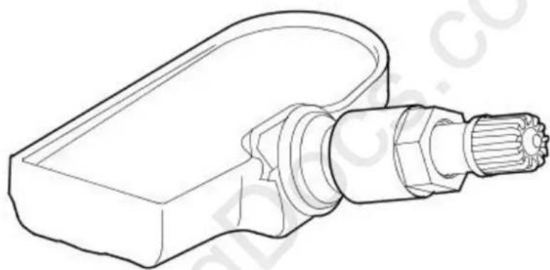
natural_image
Technical line drawing of a mechanical component with threaded end (no text or symbols)E45553
The TPMS uses active tire pressure sensors which are located on each wheel, inside the tire cavity. The sensor incorporates the tire valve and is secured in the wheel by a nut on the outside of the wheel. The sensor contains a Printed Circuit Board (PCB) which houses a Positive Temperature Coefficient (PTC) sensor, a Piezo pressure sensor, a radio receiver and transmitter and a lithium battery.
The tire pressure sensors use the PTC sensor and the Piezo sensor to periodically measure the pressure and temperature of the air inside the tire. The data is transmitted by RF data signals at 315 MHz.
The RF transmission from the sensor contains a unique identification code in its transmission data. This allows the TPMS to identify the wheel on the vehicle. If the sensor is replaced on a 'running' wheel, the new sensor identification will be learnt when the vehicle is driven at speed of more than 20 km/h (12.5 mph) for 15 minutes.
The tire pressure sensor can also detect when the wheel is rotating. In order to preserve battery power, the sensor uses different transmission rates when the wheel is stationary or moving.
The care points detailed in 'Tire Changing' earlier in this section must be followed to avoid damage to the sensor. If a new sensor is fitted, a new nut, seal and washer must also be fitted and the sensor nut tightened to the correct torque as given in the Removal and Installation section of this manual.
Instrument Cluster
The warning indications to the driver are common on all vehicles fitted with TPMS. The driver is alerted to system warnings by a low tire pressure warning indicator in the instrument cluster and an applicable text message in the message center.
The TPMS module passes system status information to the instrument cluster on the high speed CAN bus. The instrument cluster then converts this data into illumination of the warning indicator and display of an appropriate message.
When the ignition is switched on, the warning indicator is illuminated for 3 seconds for a bulb check.
- NOTE: If the vehicle is not fitted with the TPMS, the warning indicator will not illuminate.
The instrument cluster checks, within the 3 second bulb check period, for a CAN bus message from the TPMS. During this time the TPMS performs internal tests and CAN bus initialization. The warning indicator will be extinguished if the TPMS module does not issue a fault message or tire pressure warning message.
If a TPMS fault warning message is detected by the instrument cluster at ignition on , the warning indicator will flash for 72 seconds after the 3 second bulb check period and then remain permanently illuminated.
If a tire pressure warning message is detected by the instrument cluster at ignition on, the warning indicator will extinguish briefly after the 3 second bulb check period, before re-illuminating to indicate a tire pressure warning.
Principles of Operation
Each time the vehicle is driven the TPMS module activates each initiator in turn to transmit a LF 125 KHz signal to each tire pressure sensor. The LF signal is received by the tire pressure sensor which responds by transmitting a 315 MHz signal which is received by the RF antenna. The signal contains coded data which corresponds to sensor identification, air pressure, air temperature and acceleration data and is passed to the TPMS module.
When the vehicle has been parked for more than 15 minutes and then driven at a speed of more than 12.5 mph (20 km/h), the initiators fire in turn for 18 seconds in the following order:
- Front left
● 18 second pause (for the TPMS module to detect a response from the tire pressure sensor) - Front right
• 18 second pause - Rear right
• 18 second pause - Rear left
• 18 second pause.
Each tire pressure sensor responds in turn which allows the TPMS module to establish the sensor positions at the start of the drive cycle. This process is repeated up to 3 times but less if the sensor positions are already known. The process is known as 'Auto Location' and takes 2 to 5 minutes to complete.
During this period the tire pressure sensors transmit at regular intervals, once every 15 seconds. For the remainder of the drive cycle the tire pressure sensors transmit once every 60 seconds or more often if a change of tire pressure is sensed until the vehicle stops and the TPMS returns to the parking mode.
Once the wheel positions have been established, the initiators stop transmitting the LF signal and do not transmit again until the vehicle has been parked for more than 15 minutes.
The TPMS enters 'Parking Mode' after the vehicle speed has been less than 20 km/h (12.5 mph) for 15 minutes. In parking mode the tire pressure sensors transmit a coded RF signal once every 13 hours. If the tire pressure decreases by more than 0.06 bar (1 lbf/in ^2 ), the sensor will transmit more often if pressure in the tire is being lost.
Wheels and Tires - Wheels and Tires
Diagnosis and Testing
General notes
Factory installed tires and wheels are designed to operate satisfactory when inflated to the recommended inflation pressures; refer to the Specifications sub-section. The recommended pressures apply to vehicle loads up to and including full-rated load capacity.
Correct tire pressures and driving technique have an important influence on tire life. Heavy cornering, excessively rapid acceleration and unnecessary sharp braking increase tire wear.
Replacement tires should follow the recommended:
Size.
- Speed rating.
- Load range.
- Radial construction type.
The use of any other size or type may seriously affect:
- Safety.
- Ride.
- Handling.
- Speedometer and odometer calibration.
• Vehicle ground clearance. - Tire clearance between body and chassis.
- Wheel bearing life
- Brake cooling
Wheels need to be renewed when:
- Impact damaged.
- Heavily corroded.
- Porous.
- Wheel stud holes or seats become damaged.
• They have excessive radial or lateral runout.
Safety notes
- WARNINGS:

Do not mix different types of tires on the same vehicle. Handling may be seriously affected resulting in loss of control. Failure to these instructions may result in personal injury.

When using winter tires, observe the direction of the sidewall moulded indicators; correct tire rotational direction is critical. Failure to these instructions may result in personal injury.

A tire and wheel must always be correctly matched. Wider or narrower tires than recommended could cause danger through sudden on. Failure to follow these instructions may result in personal injury.

When using the temporary spare wheel, maximum speed must not exceed 50 mile/h (80 km/h). Drive with caution and replace with specified wheel / tire assembly as soon as possible. Failure to follow these instructions may result in personal injury.

Traction control (if available) must not be engaged with a temporary spare wheel fitted. Failure to follow these instructions may result sonal injury.

When changing a wheel, make sure that the vehicle cannot move. Always apply the parking brake and select the transmission park on. Failure to follow these instructions may result in personal injury.

Never run the engine with one wheel off the ground, for example, when changing the wheel. The wheel resting on the ground may the vehicle to move. Failure to follow these instructions may result in personal injury.

Tighten the wheel nuts to specification. Too tight may cause damage, too loose may allow the wheel to become detached. Failure to these instructions may result in personal injury.

Use only wheels and wheel nuts supplied by Jaguar. Aftermarket wheels or wheel nuts may not fit or function correctly and could injury or damage. Failure to follow these instructions may result in personal injury.
Inspection and Verification
- Verify the customer's concern by driving the vehicle.1.
- Visually inspect for obvious signs of damage: 2.
Visual Inspection Chart
| Mechanical |
| Incorrect tire pressure |
| Wheel imbalance |
| Tires worn beyond tread wear indicators |
| Cuts |
| Abrasions |
| Bulges (blister) |
| Ply separation |
| Embedded objects |
| Impact damage |
| Incorrect speed rating |
| Incorrect load rating |
| Incorrect rotational direction |
-
- If an obvious cause for an observed or reported concern is found, correct the cause (if possible) before proceeding to the next step.
-
If the concern is not visually evident, verify the symptom and refer to Symptom Chart.4.
Tire Wear Inspection
To maximize tire performance, inspect the tires for signs of incorrect inflation and uneven wear which may indicate a need for balancing, rotation or front suspension alignment. Tires should also be checked frequently for cuts, stone bruises, abrasions, blisters, and for objects that may have become embedded in the tread. More frequent inspections are recommended when rapid or extreme temperature changes occur or when road surfaces are rough or occasionally littered with debris.
Tire Wear Diagnosis
New tires should be installed if the wear indicators are exposed or if there is severe shoulder wear. Shoulder wear is usually caused by either excessive camber or excessive toe on radial tires.
Sometimes incorrect rear toe settings or damaged struts will cause severe cupping' or scalloped' tire wear on non-drive wheels.
Incorrect rear toe alignment will also cause other unusual wear patterns.
Road Test
A tire vibration diagnostic procedure always begins with a road test. The road test and customer interview (if available) will provide much of the information needed to find the source of a vibration.
During the road test, drive the vehicle on a road that is smooth and free of undulations. If vibration is apparent, note and record the following:
• The speed at which the vibration occurs.
- What type of vibration occurs in each speed range. - mechanical or audible.
- How the vibration is affected by changes in the following: - engine torque. - vehicle speed. - engine speed.
- Type of vibration-sensitivity: torque sensitive, vehicle speed sensitive or engine speed sensitive.
The following explanations help isolate the source of the vibration.
Torque Sensitive
This means that the condition may be improved or made worse by accelerating, decelerating, coasting, maintaining a steady vehicle speed or applying engine torque.
Vehicle Speed Sensitive
This means that the vibration always occurs at the same vehicle speed and is not affected by engine torque, engine speed or the transmission gear selected.
Engine Speed Sensitive
This means that the vibration occurs at varying vehicle speeds when a different transmission gear is selected. It may sometimes be isolated by increasing or decreasing engine speed with the transmission in NEUTRAL or by stall testing with the transmission in gear. If the condition is engine speed sensitive, the cause is probably not related to the tires.
If the road test indicates that there is tire whine, but no shake or vibration, the noise originates with the contact between the tire and the road surface.
A thumping noise usually means that the tire has a flat or soft spot making a noise as they slap the roadway. Tire whine may be distinguished from axle noise. Tire whine remains the same over a range of speeds.
Symptom Chart
| Symptom Possible Sources Action | ||
| Tires show excess wear on edge of treads | * Tires under-inflated Correct pressure to specification. | |
| * Vehicle overloaded Correct as required. | * | |
| Tires show excess wear on edge of treads (having the correct tire pressures). | * Incorrect toe setting Set to specification. For additional information refer to Section 204-00 Suspension System - General Information | |
| Tires show excess wear in center of tread. | * Tires over-inflated Correct pressure to specification. | * |
| Other excessive tire wear problems | * Incorrect tire pressure Correct pressure to specification. | |
| * Incorrect tire / wheel usage Install correct tire and wheel combination. | ||
| * Loose or leaking dampers Tighten or install a new as necessary. For additional information refer to Section 204-01 Front Suspension or Section 204-02 Rear Suspension. | ||
| * Geometry out of alignment | * Check and adjust. | |
| * Loose, worn or damaged suspension components | * Inspect, repair or install a new as necessary. | |
| * Wheel and tire assembly out of balance | * Balance wheel and tire assembly. | |
| * Excessive lateral or radial runout of wheel or tire | Check, repair or install a new as necessary. Refer to the procedure in this section. | |
| Wheel mounting is difficult Incorrect application or mismatched parts, including wheel studs and wheel nuts. Corroded, worn or damaged parts | * Clean or install a new part. | |
| Wobble or shimmy affecting wheel runout | * Damaged wheel (eventually damaging wheel bearings and causing uneven tire wear) | * Inspect wheel rims for damage and runout. Install a new wheel rim as necessary. |
| Excessive vibration, rough steering or severe tire wear | * Loose or incorrect attaching parts Tighten or install | *new parts. |
| Vehicle vibrations Tires / wheels mismatched Install correct tire / wheel combination. | * | |
| * Inflation pressure too high or low Correct pressure to specification. | ||
| * Uneven tire wear Refer to Diagnosis and Testing in this section. | ||
| * Out-of-balance wheel, tire, wheel hub or disc assembly | * Determine the out-of-balance component and balance or install a new part. | |
| * Damaged or distorted wheel from road impact hazard or incorrect handling | * Install a new wheel. | |
| * Excessive radial runout Install a new wheel or tire. | Check for incorrect wheel and tire specifications. | |
| * Excessive lateral runout Install a new wheel or tire. | ||
| * Incorrectly seated tire Remount the tire. | * | |
| * Loose wheel mountings - damaged wheel studs, wheel nuts, worn or broken wheel hub face or foreign material on mounting faces | * Tighten or install new parts. Clean mounting surfaces. | |
| * Defective wheel bearings Install a new bearing set. | *For additional information refer to Section 204-01 Front Suspensionor Section 204-02 Rear Suspension | |
| * Brake disc imbalance | * For additional information refer to Section Section 206-00 Brake System - General Information | |
| * Water in tires | * Remove water. | |
| * Loose engine or transmission mounts | * Tighten or install a new mount. | |
| * Incorrect front end alignment | * Align front end. For additional information refer to Section 204-01 Front Suspension | |
| * Loose or worn driveline or suspension parts | * Repair or install new parts. | |
| * Excessive driveshaft runout or imbalance | * Install a new driveshaft, for additional information refer to Section 205-01 Driveshaft | |
| * Worn or damaged flexible drive joint | * Install a new drive shaft. For additional information refer to Section 205-01 Driveshaft | |
| Damaged wheel hub stud threads | * Sliding wheel across the wheel studs during installation. Loose wheel nuts | * Install new wheel studs. |
| Broken wheel studs | * Loose or overtightened wheel nuts | * Install new wheel studs. |
| Corrosion / contamination streaks from the wheel hub wheel stud holes | * Loose wheel nuts | * Check complete assembly. Install new parts. Follow correct torque procedure. |
| Wheel difficult to remove from wheel hub | * Corrosion | * Apply a small amount of grease to the wheel hub face and spigot location. |
| Damaged wheel nuts | * Loose wheel assembly | * Install new wheel nuts. Follow correct torque procedure. |
| * Over-tightened wheel nuts | * Install new wheel nuts. Follow correct torque procedure. | |
| Frozen wheel nuts | * Corrosion or galling |  CAUTION: Do not permit lubricant to contaminate wheel hub stud holes or wheel nut seats. * If corrosion is light, wire brush away corrosion. If corrosion is excessive install new wheel studs and wheel nuts. CAUTION: Do not permit lubricant to contaminate wheel hub stud holes or wheel nut seats. * If corrosion is light, wire brush away corrosion. If corrosion is excessive install new wheel studs and wheel nuts. |
Wheels and Tires - Tire Low Pressure SensorVIN Range: J28493->V99999
Removal and Installation
Removal
- NOTE: It is strongly recommended that a new tire low pressure sensor O-ring seal, washer, nut, valve core and cap are installed each time a tire is removed and installed. The O-ring seal, washer, nut, valve core and cap must be replaced if the tire low pressure sensor is removed. Removal of the tire low pressure sensor retaining nut must be regarded as tire low pressure sensor removal. The tire low pressure sensor valve cap must always be in place except when inflating, releasing pressure or checking pressure.

natural_image
Diagram showing a car with two colored blocks and directional arrows, no text or symbols present- Remove the wheel and tire.
For additional information, refer to: Wheel and Tire (204-04 Wheels and Tires, Removal and Installation).

- CALITION: Make sure the tire bead is broken from the wheel rim 180 degrees from the tire low pressure sensor. Failure to follow this instruction may result in damage to the tire low pressure sensor.
Remove the tire.
- CAUTION: Make sure you do not push on the tire low pressure sensor valve. Failure to follow this instruction may result in damage to the valve.
Remove the tire low pressure sensor.
- Remove and discard the tire low pressure sensor retaining nut, valve core, valve cap, O-ring seal and washer.
Installation

natural_image
Technical line drawing of a handheld device with threaded shaft and two separate plastic rings (no text or symbols)E63661
- CAUTION: The base of the valve stem must be held whilst pushing on the new seal and washer. Failure to follow this instruction may result in damage to the tire low pressure sensor.
- NOTE: Make sure that the washer and O-ring seal are installed correctly. The flat face of washer must be seated against the sensor housing. The taper of O-ring seal points towards the wheel.
Install a new washer and O-ring seal.
• Install a new valve core and valve cap.

- CAUTION: Make sure solvents or cleaning agents of any type are not used to clean the tire low pressure sensor. Failure to follow this instruction may result in damage to the tire low pressure sensor.
- NOTE: If the tire low pressure sensor is replaced on a road wheel, the new tire low pressure sensor identification code will be learnt when the vehicle is first driven. If a new tire low pressure sensor is fitted to the spare wheel the identification code for that tire low pressure sensor must be programmed into the tire pressure monitoring system module. The identification code is printed on the casing of each tire low pressure sensor and is prefixed with ID.
Install the tire low pressure sensor.
- Support the base of the valve stem when installing the tire low pressure sensor.
- Hold the tire low pressure sensor against the wheel rim when tightening the retaining nut.
• Install a new tire low pressure sensor retaining nut.
- Tighten the nut to 8 Nm.
- CAUTION: Make sure no damage occurs to the tire low pressure sensor.
Install the tire and balance the wheel.
- Install the wheel and tire. For additional information, refer to: Wheel and Tire (204-04 Wheels and Tires, Removal and Installation).
Wheels and Tires - Tire Pressure Monitoring System (TPMS) Front AntennaVIN Range: J28493->V99999
Removal and Installation
Removal

- Raise and support the vehicle.
For additional information, refer to: Jacking (100-02 Jacking and Lifting, Description and Operation). - NOTE: Left-hand shown, right-hand similar.
Detach the wheel arch liner.

natural_image
Technical line drawing of a mechanical component with an arrow indicating a specific part (no text or symbols present)- NOTE: Left-hand shown, right-hand similar.
Disconnect the tire pressure monitoring system front antenna electrical connector.
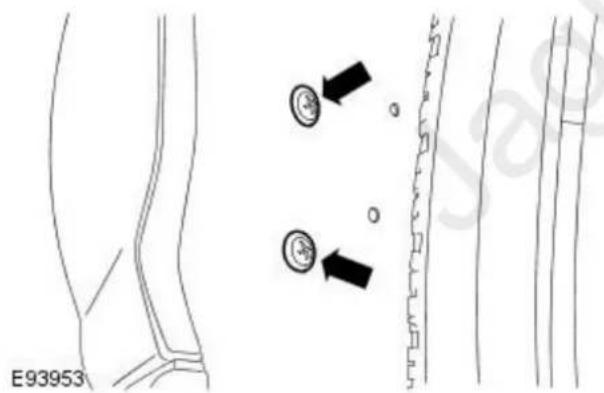
- NOTE: Left-hand shown, right-hand similar.
Remove the tire pressure monitoring system front antenna.
Installation
- To install, reverse the removal procedure.
Wheels and Tires - Tire Pressure Monitoring System (TPMS) Main AntennaVIN Range: J28493->V99999
Removal and Installation
Removal
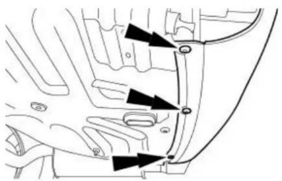
natural_image
Technical diagram of a vehicle's internal components with directional arrows indicating flow or movement (no text or labels)E94324
- Raise and support the vehicle.
For additional information, refer to: Jacking (100-02 Jacking and Lifting, Description and Operation). -
Detach the rear bumper cover.
-
Disconnect the tire pressure monitoring system main antenna electrical connector.
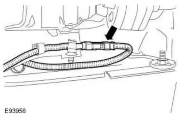
natural_image
Technical diagram of a mechanical assembly with hoses and bolts, no visible text or symbols- Release the tire pressure monitoring system main antenna electrical harness.

natural_image
Technical diagram of a car engine component with hoses and valve (no text or symbols)- Remove the tire pressure monitoring system main antenna.

natural_image
Technical line drawing of a mechanical component with no visible text or symbols
natural_image
Technical line drawing of a mechanical component with no visible text or symbols- To install, reverse the removal procedure.
- Tighten to 5 Nm.
Wheels and Tires - Tire Pressure Monitoring System (TPMS) ModuleVIN Range: J28493->V99999
Removal and Installation
Removal

natural_image
Technical line drawing of a mechanical component with arrows indicating motion or force direction (no text or symbols)- Remove the rear seat cushion.
For additional information, refer to: Rear Seat Cushion (501-10 Seating, Removal and Installation). - Remove the rear scuff plate trim panel.
For additional information, refer to: Rear Scuff Plate Trim Panel (501-05 Interior Trim and Ornamentation, Removal and Installation). - Reposition the floor covering.
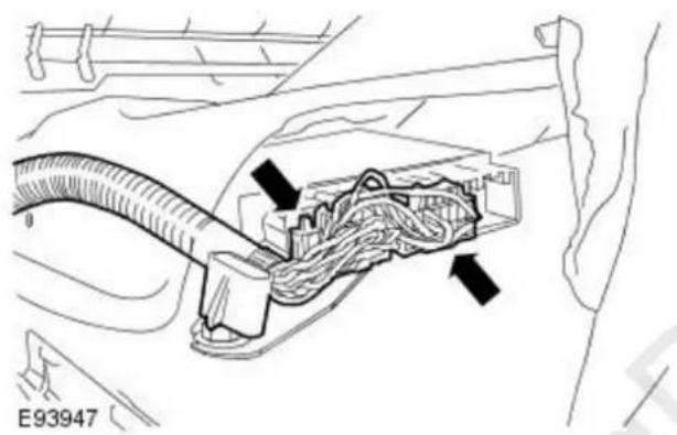
natural_image
Technical diagram of a car's electrical connector with cable and wiring (no text or symbols)- Disconnect the tire pressure monitoring system module electrical connectors.

natural_image
Diagram of a cable being inserted into a car body, showing connector and cable connection (no text or symbols)- Reposition the tyre pressure monitoring system module harness.

natural_image
Technical diagram of a mechanical assembly with two black arrows pointing to specific components (no text or symbols present)- Reposition the tire pressure monitoring system module.
- Remove the retaining nuts.
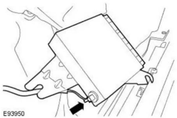
natural_image
Technical line drawing of a mechanical component with a black arrow indicating a force or adjustment (no text or symbols present)- Remove the tire pressure monitoring system module.
- Disconnect the external antenna connector.
Installation
- To install, reverse the removal procedure.
- Tighten to 5 Nm.

natural_image
Technical diagram of a mechanical component with two black arrows indicating features, no readable text or symbols present.Wheels and Tires - Tire Pressure Monitoring System (TPMS) Rear AntennaVIN Range: J28493->V99999
Removal and Installation
Removal

natural_image
Diagram of a car interior showing a valve and cable connector (no text or symbols)- Raise and support the vehicle.
For additional information, refer to: Jacking (100-02 Jacking and Lifting, Description and Operation).
- NOTE: Left-hand shown, right-hand similar.
Disconnect the tire pressure monitoring system rear antenna electrical connector.

- NOTE: Left-hand shown, right-hand similar.
Remove the tire pressure monitoring system rear antenna.
Installation
- To install, reverse the removal procedure.
Removal

natural_image
Technical diagram of a mechanical component with five directional arrows indicating flow or force (no text or symbols)- ACTION: Do not use heat to loosen a seized wheel nut, excessive heat may cause damage to the wheel and the wheel bearings. Loosen the wheel nuts.

natural_image
Technical diagram of a car wheel with six blades and mounting holes (no text or symbols)- Raise and support the vehicle. For additional information refer to Section 100-02 Jacking and Lifting.
- Remove the wheel and tire assembly.
Installation
Vehicles with steel wheels

natural_image
Diagram of a car wheel with six directional arrows indicating flow or force, no text or symbols present.- WARNINGS:
Make sure that there is no contamination of the wheel, hub or brake disc contact surfaces. Installation without metal to metal contact at the mounting surfaces may cause the wheel nuts to loosen and allow the wheel to detach while the vehicle is in motion. Failure to follow these instructions may result in personal injury.
Apply a small amount of grease to the hub and wheel mating surfaces before installation. Make sure that the grease does not come into contact with the wheel studs or vehicle braking system components. Failure to follow these instructions may result in personal injury.
To install, reverse the removal procedure.
- Tighten to 80 Nm.
Vehicles with aluminium wheels
- WARNINGS:

natural_image
Technical diagram of a mechanical component with five arrows indicating directional flow or force vectors (no text or symbols present)Make sure that there is no contamination of the wheel, hub or brake disc contact surfaces. Installation without metal to metal contact at the mounting surfaces may cause the wheel nuts to loosen and allow the wheel to detach while the vehicle is in motion. Failure to follow these instructions may result in personal injury.
Apply a small amount of grease to the hub and wheel mating surfaces before installation. Make sure that the grease does not come into contact with the wheel studs or vehicle braking system components. Failure to follow these instructions may result in personal injury.
To install, reverse the removal procedure.
- Tighten to 103 Nm.
Driveline System - General Information - Driveline System
Description and Operation
The driveline transfers engine torque to the drive wheels. On vehicles with 2.0L or diesel engines the power is transmitted through the transaxle to the front drive halfshafts. On vehicles with 2.5L and 3.0L engines the power is transmitted through the transaxle to the transfer case. The transfer case then splits the torque 40% to the front drive halfshafts and 60% to the driveshaft which is connected to the rear drive differential and the rear drive halfshafts.
For additional information, refer to: Wheels and Tires (204-04 Wheels and Tires, Description and Operation).
For additional information, refer to: Front Drive Halfshafts (205-04 Front Drive Halfshafts, Description and Operation).
For additional information, refer to: Driveshaft (205-01 Driveshaft, Description and Operation).
For additional information, refer to: Transfer Case (308-07 Transfer Case, Description and Operation).
For additional information, refer to: Rear Drive Halfshafts (205-05 Rear Drive Halfshafts, Description and Operation).
For additional information, refer to: Rear Drive Axle and Differential (205-02 Rear Drive Axle/Differential, Description and Operation).
For additional information, refer to: Manual Transaxle - Vehicles With: 6-Speed Manual Transaxle - MMT6 (308-03 Manual Transmission/Transaxle, Description and Operation).
For additional information, refer to: Transmission Description (307-01 Automatic Transmission/Transaxle, Description and Operation).
The engine is installed at a specific angle. This is determined by the engine mounts. If the engine angle is out of specification, the engine mounts must be inspected for damage and new ones installed if necessary.
Driveline Vibration
Driveline vibration exhibits a higher frequency and lower amplitude than high-speed shake. Driveline vibration is directly related to the speed of the vehicle and is usually noticed at various speed ranges. Driveline vibration can be felt as a tremor in the floorpan or is heard as a rumble, hum or boom. Driveline vibration can exist in all drive modes, but may exhibit different symptoms depending upon whether the vehicle is accelerating, decelerating, cruising or coasting. Check the driveline angles if the vibration is particularly noticeable during acceleration or deceleration, especially at lower speeds.
In order to diagnose vibrations in the driveshaft, refer to the Jaguar Approved Diagnostic System.
Driveline Angle
On vehicles with 2.0L or diesel engines the driveline angularity is the angular relationship between the transaxle and the halfshafts. On vehicles with 2.5L and 3.0L engines the driveline angularity is the angular relationship between the transfer case drive pinion, the driveshaft and the rear differential drive pinion. On all engines variations the factors determining driveline angularity include ride height and engine mounts.
If the wheels and tires and driveline angle are not the cause, carry out the NVH tests to determine whether the concern is caused by a condition in the driveline.
For additional information, refer to: Noise, Vibration and Harshness (NVH) (100-04 Noise, Vibration and Harshness, Description and Operation).
Driveline System - General Information - Driveline System
Diagnosis and Testing
Inspection and Verification
Certain driveline conditions are also common to the engine, transaxle, transfer case, wheel bearings, wheels and tires and other parts of the vehicle. For this reason, make sure the cause of the trouble is in the driveline before adjusting, repairing or installing any new components. For additional information, refer to Section 100-04 Noise, Vibration and Harshness.
- Verify the customer concern by carrying out a road test of the vehicle.1.
- Visually inspect for obvious signs of mechanical damage.2.
-
- If an obvious cause for an observed or reported concern is found, correct the cause (if possible) before proceeding to the next step.
- If the concern is not visually evident, verify the symptom and refer to the Symptom Chart.4.
Transfer Case, Front Transaxle and Axle Noise
Gear Howl and Whine
Howling or whining of the ring gear and drive pinion are due to an incorrect gear pattern, gear damage or incorrect bearing preload.
Bearing Whine
Bearing whine is a high-pitched sound similar to a whistle. It is usually caused by worn/damaged pinion bearings. Bearing noise occurs at all driving speeds. This distinguishes it from gear whine which is speed dependent.
As noted, pinion bearings make a high-pitched, whistling noise, usually at all speeds. If however there is only one pinion bearing that is worn/damaged, the noise may vary in different driving phases.
A wheel bearing noise can be mistaken for a pinion bearing noise.
Knock
Knock, which can occur on all driving phases, has several causes including damaged teeth or gearset.

natural_image
Diagram showing gear and gear meshing with directional arrows indicating motion (no text or symbols)GE0793A
A gear tooth damaged on the drive side is a common cause of the knock.
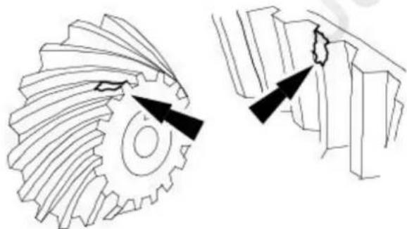
natural_image
Technical line drawing of gear and mechanical components with arrows indicating motion (no text or symbols)GE0792A
Clunk
Clunk is a metallic noise heard when the automatic transaxle is engaged in REVERSE or DRIVE. The noise may also occur when the throttle is applied or released. Clunk is caused by backlash in the driveline or loose suspension components.
Bearing Rumble
Bearing rumble is usually caused by a worn/damaged wheel bearing. The lower pitch is because the wheel bearing turns at only about one-third of the driveshaft speed. Wheel bearing noise may also be high-pitched, similar to gear noise, but will be evident in all four driving modes.
Symptom Chart
| Noise is at constant tone over a narrow vehicle speed range. Usually heard on light driving and coasting conditions | * Rear drive differential.* Transfercase.* Transaxle. | * For additional information, refer to Pinpoint Test A |
| Noise is the same on driving or coasting. | * Road.* Wheel bearing. | * Normal conditions.* CHECK and INSTALL a new wheel bearing as necessary. For additional information, refer to Section 204-02 Rear Suspension. |
| * Worn or damaged driveshaft joint. INSTALL new components as necessary. | ||
| * Driveshaft center bearing. INSTALL new components as necessary. | ||
| Noise is produced with the vehicle standing and driving | * Engine For additional information, refer to Section 303-00 Engine System - General Information. | |
| * Transmission For additional information, refer to Section 307-01A Automatic Transmission/TransaxleSection 307-01B Automatic Transmission/Transaxle. For additional information, refer to Section 308-03 Manual Transmission/Transaxle. | ||
| Noise is more pronounced while turning | * Front or rear differential side gears and pinion gears. | * For additional information, refer to Section 205-02 Rear Drive Axle/Differential and Section 308-07 Transfer Case. |
| Loud clunk in the driveline when Shifting from Reverse to Drive. | * Engine idle speed set too high.* Engine mount. | * CHECK and adjust as necessary.* INSPECT and INSTALL new engine mounts as necessary. |
| * Transaxle Mount. INSPECT and INSTALL new transaxle mounts as necessary. | ||
| * Transaxle. For additional information, refer to Section 307-01A Automatic Transmission/TransaxleSection 307-01B Automatic Transmission/Transaxle and Section 308-03 Manual Transmission/Transaxle. | ||
| * Suspension. INSPECT and INSTALL new suspension components as necessary. | ||
| * Backlash in the driveline. INSTALL new components as necessary. | ||
| Clicking, popping or grinding noises | * Inadequate or contaminated lubrication in the constant velocity (CV) joints.* Another component contacting the axle shaft.* Wheel bearings, brakes or suspension components. | * INSPECT, CLEAN and LUBRICATE with new grease as necessary.* INSPECT and REPAIR as necessary.* INSPECT and INSTALL new components as necessary. |
| Vibration at high speeds. Out | * of-balance wheels and tires. INSTALL new wheels and tires as necessary. For additional information, refer to Section 204-04 Wheels and Tires. | |
| * Driveline out of balance/misalignment. For additional information, refer to the approved Jaguar diagnostic system. | ||
| Shudder or vibration during acceleration. | * Powertrain/driveline misalignment. CHECK for misalignment. INSTALL new components as necessary. | |
| * High CV joint operating angles caused by incorrect ride height. | * CHECK the ride height and VERIFY the correct spring rate. INSTALL new components as necessary. | |
| Lubricant leak. | * Transaxle, transfer case or rear drive differential vent. | * INSTALL new components as necessary. |
| * Transaxle halfshaft seal, transfer case halfshaft seal, transaxle to transfer case O/ring seal, transfer case drive pinion seal, rear drive differential pinion seal or rear drive halfshaft seal. | * INSTALL new components as necessary. | |
| * Filler plug. | * INSTALL new components as necessary. | |
| * Axle rear cover joint. | * INSTALL new components as necessary. | |
PINPOINT TEST A : EXCESSIVE DRIVELINE NOISE
| TEST CONDITIONS | DETAILS/ RESULTS/ ACTIONS |
| A1: CHECK NOISE FROM VEHICLE ON ROAD TEST | |
| 1 Road test vehicle to determine load and speed conditions when noise occurs. | |
| 2 Assess the noise with different gears selected. | |
| Does the noise occur at the same vehicle speed?YesINSTALL a new final drive. TEST the system for normal operationNoREFER to Section 204-04 Wheels and Tires, Section 205-01 Driveshaft, Section 205-04 Front Drive Halfshafts, Section 205-05 Rear Drive Halfshafts, Section 303-00 Engine System - General Information, Section 307-01A Automatic Transmission/TransaxleSection 307-01B Automatic Transmission/Transaxle, Section 308-03 Manual Transmission/Transaxle andSection 308-07 Transfer Case. | |
Torque Specifications
| Description Nm lb-ft lb-in | |||
| Driveshaft center bearing retaining bolts 25 18 - | |||
| Driveshaft front universal joint retaining bolts 44 32 - | |||
| Driveshaft rear universal joint retaining bolts 44 32 - |
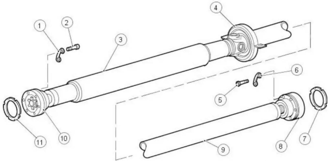
VUJ0002769
| Item Part Number Description | |
| 1 — Link washer | |
| 2 — Driveshaft universal joint retaining bolt | |
| 3 — Driveshaft front collapsible tube | |
| 4 — Driveshaft center bearing | |
| 5 — Driveshaft universal joint retaining bolt | |
| 6 — Link washer | |
| 7 — Paper gasket | |
| 8 — Driveshaft rear universal joint | |
| 9 — Driveshaft rear tube | |
| 10 — Driveshaft front universal joint | |
| 11 — Paper gasket |

WARNING: Under no circumstances must a 2004.25 MY or earlier driveshaft assembly be fitted to a later vehicle. Failure to follow this action may result in personal injury.

CAUTION: To preserve 'drive line' refinement, individual parts, other than fixings, MUST NOT be renewed. In the event of any balance driveshaft component related concern, the complete assembly must be renewed. Under no circumstances may the universal joint beived from the driveshaft (or its fixings be loosened). Do not drop or subject the driveshaft to damage.
- NOTE: 2004.25 MY driveshaft assemblies may be fitted to earlier model year vehicles. For modification details refer to Driveshaft in this section.
- NOTE: All driveshaft assemblies are balanced. If undercoating the vehicle, protect the driveshaft, universal joints and the drive half shafts to prevent over-spray of the undercoating material.
The driveshaft consists of the following:
- A two piece welded steel tube.
• A center bearing. - Two universal joints.
Universal Joint
The universal joints are:
- A lubed-for-life design and require no lubrication in service.
For additional information, refer to Section 205-00 Driveline System - General Information.
- For additional information, refer to the approved Jaguar diagnostic system.
Removal
- NOTE: Removal of the driveshaft rear universal joint shown, removal of the driveshaft front universal joint similar.

- Raise and support the vehicle.
For additional information, refer to: Lifting (100-02 Jacking and Lifting, Description and Operation).
- NOTE: Mark the position of the driveshaft in relation to the drive pinion flange.
Remove two opposing driveshaft universal joint retaining bolts.

natural_image
Technical diagram of a mechanical assembly with two bolted components and a grid-patterned background (no text or symbols)- Loosen the remaining driveshaft universal joint retaining bolts.
- Using a suitable tool, detach the driveshaft from drive pinion flange.

natural_image
Technical diagram of a mechanical assembly with two black arrows indicating connection points (no text or symbols present)- CAUTION: Make sure the outer casing of the driveshaft universal joint is secured to the driveshaft universal joint through the securing holes. Failure to follow this instruction may invalidate the warranty of the driveshaft.
Using suitable tie straps, secure the outer casing of the driveshaft universal joint.

natural_image
Technical diagram of a mechanical assembly with bolted components and grid background (no text or symbols)- CAUTION: Make sure the front and rear driveshaft sections are supported.
- NOTE: If installed, remove and discard the gasket.
Detach the driveshaft universal joint.
- Remove and discard the driveshaft retaining bolts and link washers.
- Repeat the above procedure for the driveshaft front universal joint.

- CAUTION: Make sure the front and rear driveshaft sections are supported.
Remove the driveshaft.
- Remove driveshaft center bearing retaining bolts.
Installation

- CAUTION: Make sure the front and rear driveshaft sections are supported.
Install the driveshaft.
- Loosely install the driveshaft center bearing retaining bolts.
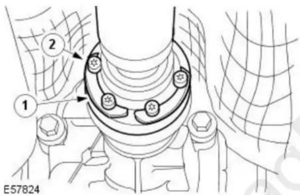
- CAUTIONS:
INSTALLING A NEW DRIVESHAFT. If a new driveshaft is to be installed, no gasket is required between the driveshaft and the drive pinion flange. Failure to follow this instruction may result in damage to the vehicle.
INSTALLING THE ORIGINAL DRIVESHAFT. If a gasket was removed from between the driveshaft and the drive pinion flange on the driveshaft removal procedure, make sure to install a new gasket. If no gasket was removed from between the driveshaft and the drive pinion flange on the driveshaft removal procedure, a new gasket is not required. Failure to follow this instruction may result in damage to the vehicle.
- NOTE: If a new driveshaft is to be installed align the 'H' on the rear drive axle flange with the paint mark on the driveshaft.
- NOTE: Remove and discard the tie straps.
Attach the driveshaft rear universal joint.
- Install new driveshaft retaining bolt link washers.
-
Install new driveshaft retaining bolts.
-
Tighten to 44 Nm.
-
Repeat the above procedure for the driveshaft front universal joint.
- Fully tighten the driveshaft center bearing retaining bolts.
- Tighten to 25 Nm.

- Carry out a driveshaft alignment check using specifications found in underbody misalignment checks. For additional information, refer to: Underbody Misalignment Check (502-00 Uni-Body, Subframe and Mounting System, General Procedures).
Rear Drive Axle/ Differential -
General Specifications
| Item Specification | |
| Oil type M2C192A synthetic | |
| Oil capacity 1.2 liters |
Torque Specifications
| Description Nm lb-ft lb-in | |||
| Driveshaft front universal joint retaining bolts 40 30 - | |||
| Driveshaft rear universal joint retaining bolts 40 30 - | |||
| Axle front retaining bolts 90 66 - | |||
| Axle rear retaining bolt stage one | A | - | - |
| Driveshaft center bearing retaining bolts | 25 18 - | ||
| Vibration damper retaining bolt | 40* | 30 - | |
| Drive pinion flange preload lower than specification on used bearings | 1.7 | - | 15 |
| Drive pinion flange preload higher than specification on used bearings | 1.7 | - | 15 |
A = refer to the procedure for the correct torque sequence.
* Tighten existing fittings on vehicles prior to VIN J24258 to 48 Nm.
Rear Drive Axle/ Differential - Rear Drive Axle and Differential
Description and Operation

VUJ0004059
| Item Part Number Description | |
| 1 — Vibration damper bracket | |
| 2 — Axle shaft oil seal | |
| 3 — Axle housing | |
| 4 — Axle shaft oil seal | |
| 5 — Drive pinion seal | |
| 6 — Drive pinion collapsible spacer | |
| 7 — Drive pinion flange | |
| 8 — Drive pinion flange retaining nut | |
| 9 — Vibration damper |
The rear axle drive pinion receives power from the engine through the transaxle and driveshaft. The drive pinion gear rotates the differential drive gear which is bolted to the axle housing outer flange. Inside the axle housing, two differential pinion gears are mounted on a differential shaft which is pinned to the axle housing. These differential pinion gears are engaged with the differential side gears to which the axle shafts are splined. As the differential gear turns, it rotates the axle shafts and rear wheels.
When it is necessary for one wheel and axle shaft to rotate faster than the other, the faster turning differential side gear causes the differential pinion gears to roll on the slower turning differential side gear. This allows differential action between the two axle shafts.
The vibration damper is designed to damp driveshaft boom. It is bolted to the rear differential vibration damper bracket which in turn is bolted to the rear axle.
Rear Drive Axle/ Differential - Rear Drive Axle and Differential
Diagnosis and Testing
For additional information, refer to Section 205-00 Driveline System - General Information.
Rear Drive Axle/ Differential - Axle Shaft Seal
In-vehicle Repair
| Special Tool(s) | |
| Remover, Axle Shaft Oil Seal308-208 | |
| Installer, Oil Seal204-264 | |

Removal
- Remove the rear halfshaft. For additional information, refer to Section 205-05 Rear Drive Halfshafts.
- Using the special tool, remove and discard the axle shaft oil seal.
Installation
- Using the special tool, install the axle shaft oil seal.

- Install the halfshaft. For additional information, refer to Section 205-05 Rear Drive Halfshafts.
Rear Drive Axle/ Differential - Drive Pinion Flange
In-vehicle Repair
| Special Tool(s) | |
 | Torque To Turn Rotary Tool205-518 |
| 205-518 | |
 | Wrench, Flange205-053 |
| 205053 | |
 | Remover, Flange Plate204-295 |
| 204295 | |
 | Remover, Flange Boss204-266 |
| 204 | |
 | Remover, Flange Shaft204-268A |
 | Installer, Oil Seal204-264 |
| 204-204 | |
Removal
- CAUTION: The following step must be carried out to make sure the correct drive pinion flange retaining nut torque is achieved.
Remove the rear brake pads.
For additional information, refer to: Brake Pads (206-04 Rear Disc Brake, Removal and Installation). - Remove the driveshaft.
For additional information, refer to: Driveshaft (205-01 Driveshaft, Removal and Installation). - Remove the vibration damper.

natural_image
Technical line drawing of a mechanical component with a circular component and an arrow indicating direction (no text or symbols)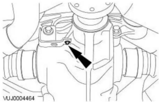
natural_image
Technical line drawing of a mechanical component with a black arrow pointing to a detail (no text or symbols present)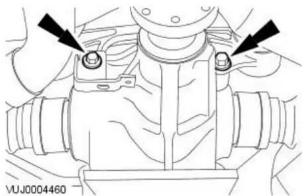
natural_image
Technical line drawing of a mechanical component with two black arrows pointing to features (no text or symbols present)
natural_image
Technical line drawing of a mechanical assembly with a black arrow pointing to a component (no text or symbols present)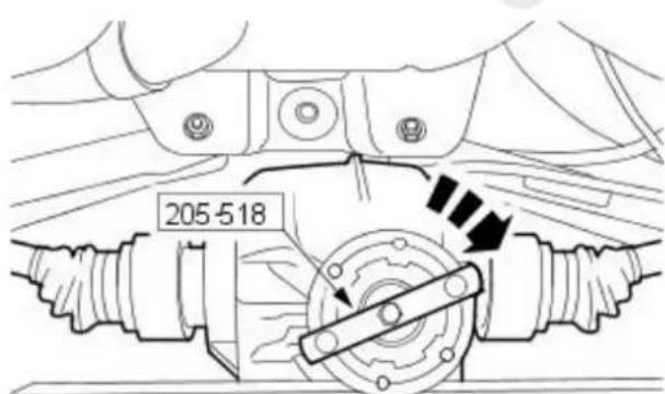
VUJ0004459
-
Remove the vibration damper retaining bolt.
-
NOTE: Support the axle assembly.
Remove the axle front retaining bolts.
- Remove the vibration damper bracket.
-
Remove the axle assembly rear retaining bolt.
-
CAUTION: Make sure CV joints do not exceed 18 degrees from the center line.
Lower the differential.
-
Install the special tool to the drive pinion flange.
-
Install a Nm (pound/inch) torque wrench on the special tool and record the torque necessary to maintain rotation of the drive pinion gear through several revolutions.

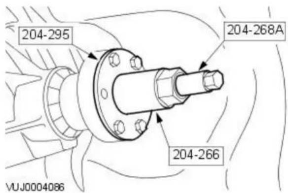

natural_image
Technical line drawing of a mechanical component with concentric rings and a black arrow indicating direction (no text or symbols)-
Using the special tool, install a breaker bar and remove and discard the drive pinion flange retaining nut.
-
NOTE: Mark the pinion flange in relation to the drive pinion stem to ensure correct alignment during installation.
Using the special tools, remove the drive pinion flange.
- Using a suitable tool, remove and discard the drive pinion seal.
Installation


natural_image
Technical line drawing of a mechanical component with concentric gears and a black arrow pointing to a feature (no text or symbols)- CAUTIONS:

Installation without the correct tool can result in early seal failure.

If the drive pinion seal becomes misaligned during installation, e it and install a new one.
- NOTE: Lubricate the lips of the new drive pinion oil seal. Use a long life grease or equivalent.
Using the special tool, install the drive pinion seal.

TION: Inspect the pinion flange seal journal for rust or ratches prior to installing the pinion flange. Polish the seal journal the crocus cloth, if required.
Install the drive pinion flange.
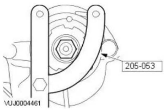
- CAUTION: Do not under any circumstance, loosen the pinion nut to reduce preload, if preload is exceeded install a new collapsible spacer and pinion nut.
Using the special tool, hold the pinion flange while tightening the drive pinion retaining nut.
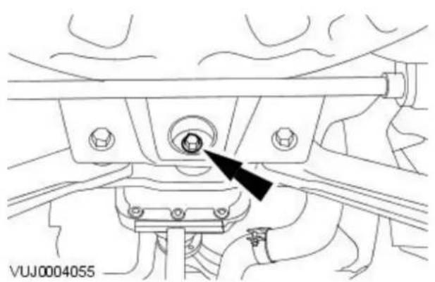
natural_image
Technical line drawing of a mechanical assembly with a black arrow pointing to a component (no text or symbols present)- CAUTION: If the preload recorded prior to disassembly is lower than the specification (1.7 Nm / 15 lb-in) for used bearings, tighten the companion flange nut until the pinion preload reaches the specification (1.7 Nm / 15 lb-in). If the preload recorded prior to disassembly is higher than the specification for used bearings, tighten the companion flange nut to the original reading as recorded.
- NOTE: Rotate the pinion to allow the pinion bearing to seat correctly. Take frequent pinion bearing torque preload measurements by rotating the pinion with a (Nm / lb-in) torque wrench.
Using the special tool, carry out a pinion bearing preload check.
- Install the axle assembly.
-
Loosely install the axle assembly rear retaining bolt.
-
Loosely install the axle assembly front retaining bolts.
• Install the vibration damper bracket.

natural_image
Technical line drawing of a mechanical component with two black arrows pointing to features (no text or symbols present)- Install the vibration damper bracket retaining bolt.

natural_image
Technical line drawing of a mechanical component with a black arrow pointing to a specific part (no text or symbols present)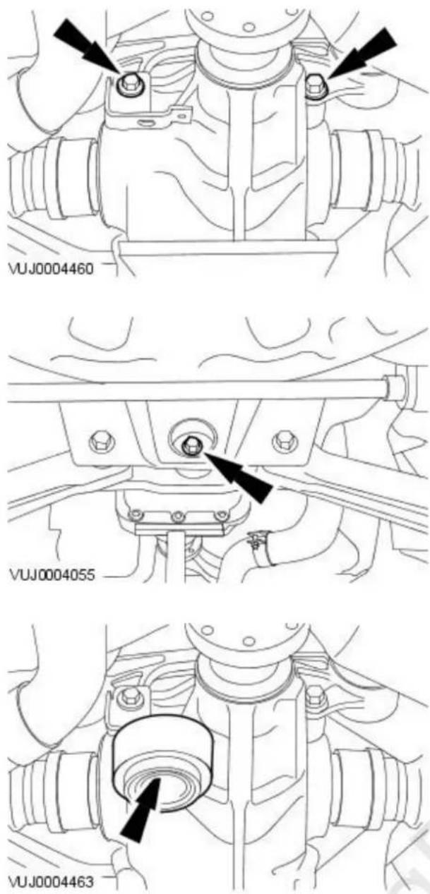
-
Tighten the axle assembly front retaining bolts to 90 Nm.
-
Tighten the axle assembly rear retaining bolt to 110 Nm and then slowly tighten to 135 Nm.
-
Install the vibration damper.
- Tighten to 48 Nm
-
Install the driveshaft. For additional information, refer to: Driveshaft (205-01 Driveshaft, Removal and Installation).
-
Install the rear brake pads. For additional information, refer to: Brake Pads (206-04 Rear Disc Brake, Removal and Installation).
Rear Drive Axle/ Differential - Drive Pinion Seal
In-vehicle Repair
| Special Tool(s) | |
 | Torque To Turn Rotary Tool205-518 |
| 205-518 | |
 | Wrench, Flange205-053 |
| 205053 | |
 | Remover, Flange Plate204-295 |
| 204295 | |
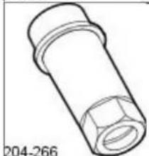 | Remover, Flange Boss204-266 |
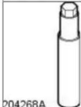 | Remover, Flange Shaft204-268A |
 | Installer, Oil Seal204-264 |
Removal
- CAUTION: The following step must be carried out to make sure the correct drive pinion flange retaining nut torque is achieved.
Remove the rear brake pads.
For additional information, refer to: Brake Pads (206-04 Rear Disc Brake, Removal and Installation). - Remove the driveshaft.
For additional information, refer to: Driveshaft (205-01, Removal and Installation). - Remove the vibration damper.

natural_image
Technical line drawing of a mechanical component with a circular component and an arrow indicating direction (no text or symbols)
natural_image
Technical line drawing of a mechanical component with a black arrow pointing to a detail (no text or symbols present)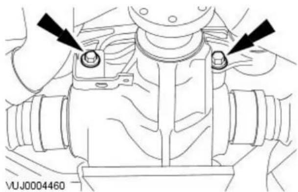
natural_image
Technical line drawing of a mechanical component with two black arrows pointing to features (no text or symbols present)
natural_image
Technical line drawing of a mechanical assembly with a black arrow pointing to a component (no text or symbols present)
VUJ0004459
-
Remove the vibration damper retaining bolt.
-
NOTE: Support the axle assembly.
Remove the axle front retaining bolts.
- Remove the vibration damper bracket.
-
Remove the axle assembly rear retaining bolt.
-
CAUTION: Make sure CV joints do not exceed 18 degrees from the center line.
Lower the differential.
-
Install the special tool to the drive pinion flange.
-
Install a Nm (pound/inch) torque wrench on the special tool and record the torque necessary to maintain rotation of the drive pinion gear through several revolutions.


natural_image
Technical line drawing of a mechanical component with concentric rings and a black arrow indicating direction (no text or symbols)Installation


natural_image
Technical line drawing of a mechanical component with concentric gears and a black arrow pointing to a feature (no text or symbols)-
Using the special tool, install a breaker bar and remove and discard the drive pinion flange retaining nut.
-
NOTE: Mark the pinion flange in relation to the drive pinion stem to ensure correct alignment during installation.
Using the special tools, remove the drive pinion flange.
-
Using a suitable tool, remove and discard the drive pinion seal.
-
CAUTIONS:

Installation without the correct tool can result in early seal failure.

If the drive pinion seal becomes misaligned during installation, e it and install a new one.
- NOTE: Lubricate the lips of the new drive pinion oil seal. Use a long life grease or equivalent.
Using the special tool, install the drive pinion seal.

TION: Inspect the pinion flange seal journal for rust or ratches prior to installing the pinion flange. Polish the seal journal the crocus cloth, if required.
Install the drive pinion flange.

- CAUTION: Do not under any circumstance, loosen the pinion nut to reduce preload, if preload is exceeded install a new collapsible spacer and pinion nut.
Using the special tool, hold the pinion flange while tightening the drive pinion retaining nut.

natural_image
Technical line drawing of a mechanical assembly with a black arrow pointing to a component (no text or symbols present)- CAUTION: If the preload recorded prior to disassembly is lower than the specification (1.7 Nm / 15 lb-in) for used bearings, tighten the companion flange nut until the pinion preload reaches the specification (1.7 Nm / 15 lb-in). If the preload recorded prior to disassembly is higher than the specification for used bearings, tighten the companion flange nut to the original reading as recorded.
- NOTE: Rotate the pinion to allow the pinion bearing to seat correctly. Take frequent pinion bearing torque preload measurements by rotating the pinion with a (Nm / lb-in) torque wrench.
Using the special tool, carry out a pinion bearing preload check.
- Install the axle assembly.
-
Loosely install the axle assembly rear retaining bolt.
-
Loosely install the axle assembly front retaining bolts.
• Install the vibration damper bracket.
natural_image
Technical line drawing of a mechanical component with two black arrows pointing to features (no text or symbols present)- Install the vibration damper bracket retaining bolt.

natural_image
Technical line drawing of a mechanical component with a black arrow pointing to a specific part (no text or symbols present)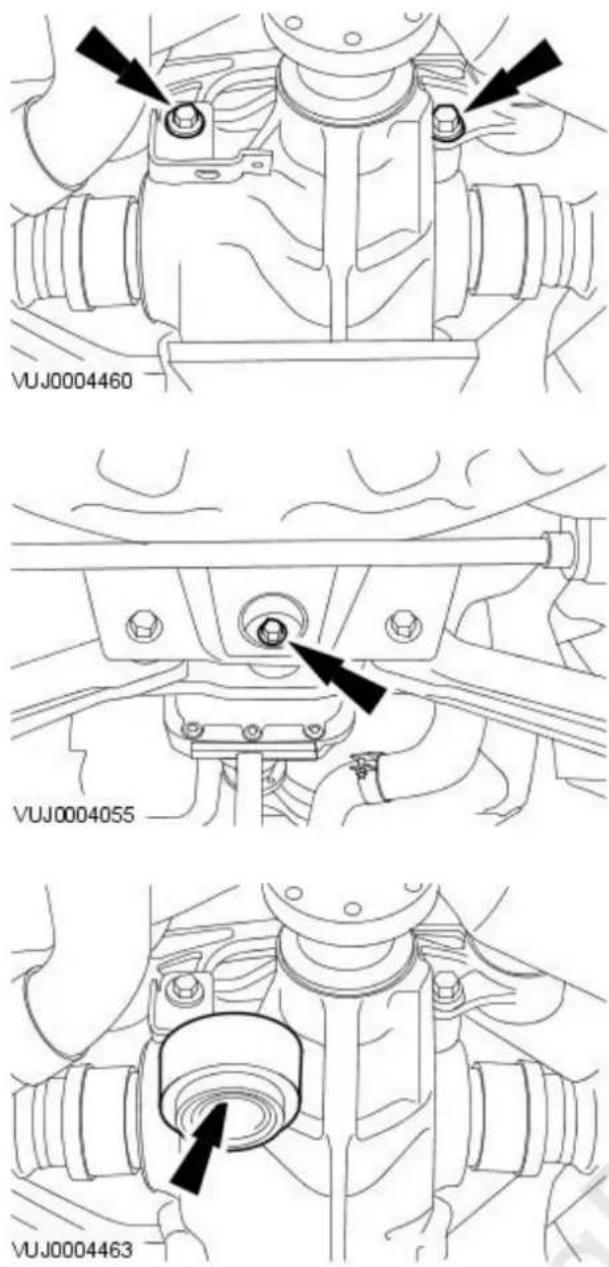
-
Tighten the axle assembly front retaining bolts to 90 Nm.
-
Tighten the axle assembly rear retaining bolt to 110 Nm and then slowly tighten to 135 Nm.
-
Install the vibration damper.
- Tighten to 48 Nm
-
Install the driveshaft. For additional information, refer to: Driveshaft (205-01, Removal and Installation).
-
Install the rear brake pads. For additional information, refer to: Brake Pads (206-04 Rear Disc Brake, Removal and Installation).
Removal

natural_image
Diagram of a car engine compartment showing internal components and directional arrows (no text or labels)VUJ0004053
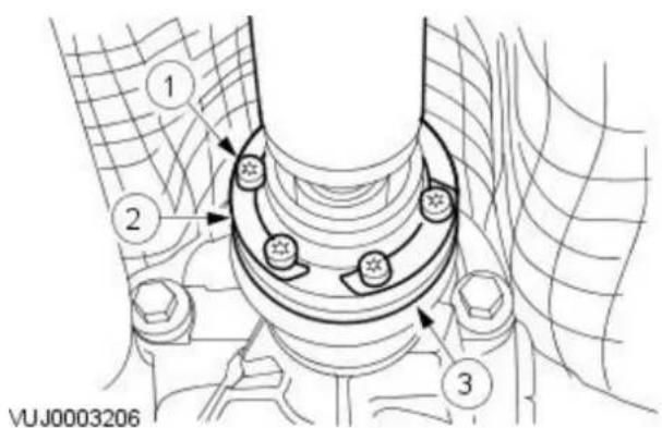
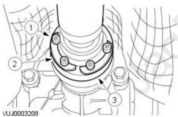

- Remove the left-hand rear halfshaft. For additional information, refer to: Rear Halfshaft (205-05 Rear Drive Halfshafts, Removal and Installation).
-
Loosely install the rear wheel knuckle retaining bolts.
-
CAUTION: Support the driveshaft front and rear sections. Failure to follow this instruction may result in damage to the vehicle.
Detach the driveshaft front universal joint.
- Remove and discard the driveshaft front universal joint retaining bolts.
- Remove and discard the driveshaft retaining bolts link washers.
- Detach the driveshaft front universal joint.
-
Remove and discard the gasket.
-
Detach the driveshaft rear universal joint.
-
Remove and discard the driveshaft rear universal joint retaining bolts.
- Remove and discard the driveshaft retaining bolts link washers.
- Detach the driveshaft rear universal joint.
-
Remove and discard the gasket.
-
CAUTION: Support the driveshaft front and rear sections.
Remove the driveshaft.
- Discard the retaining bolts.

natural_image
Technical line drawing of a mechanical assembly with a circular component and an arrow indicating direction (no text or symbols)
natural_image
Technical line drawing of a mechanical component with a black arrow pointing to a detail (no text or symbols present)
natural_image
Technical line drawing of a mechanical component with two black arrows pointing to features (no text or symbols present)
natural_image
Technical line drawing of a mechanical assembly with a black arrow pointing to a circular component (no text or symbols present)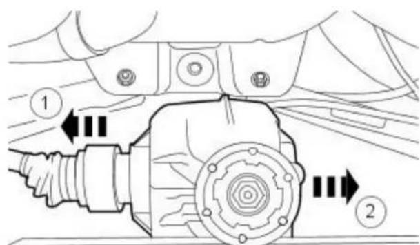
VUJ0004056
-
Remove the vibration damper.
-
Remove the vibration damper bracket retaining bolt.
-
NOTE: Support the axle assembly.
Remove the axle assembly front retaining bolts.
- Remove the vibration damper bracket.
- Remove and discard the axle assembly rear retaining bolt and lower the axle assembly.
- Remove and Discard the axle assembly washer.
- NOTE: The halfshaft is retained in the differential by a spring clip.
Remove the axle assembly.
- Using a suitable pry tool detach the rear halfshaft.
- Remove the axle assembly.
Installation
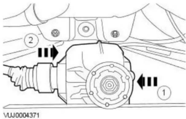

natural_image
Technical line drawing of a mechanical assembly with a black arrow pointing to a component (no text or symbols present)
natural_image
Technical line drawing of a mechanical component with two black arrows pointing to features (no text or symbols present)
natural_image
Technical diagram of a mechanical component with a black arrow pointing to a detail (no text or symbols present)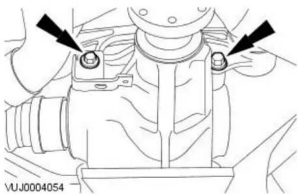
natural_image
Technical line drawing of a mechanical component with two black arrows pointing to features (no text or symbols present)- NOTE: Support the axle assembly.
- NOTE: When installing the halfshaft make sure the spring clip is fully engaged in the differential.
Install the axle assembly.
- Install the axle assembly.
-
Install the halfshaft into the axle assembly.
-
NOTE: Install a new axle assembly washer.
Loosely install new axle assembly rear retaining bolt.
- Loosely install the axle assembly front retaining bolts.
• Install the vibration damper bracket. - Install the vibration damper bracket retaining bolt.
- Tighten to 90 Nm.
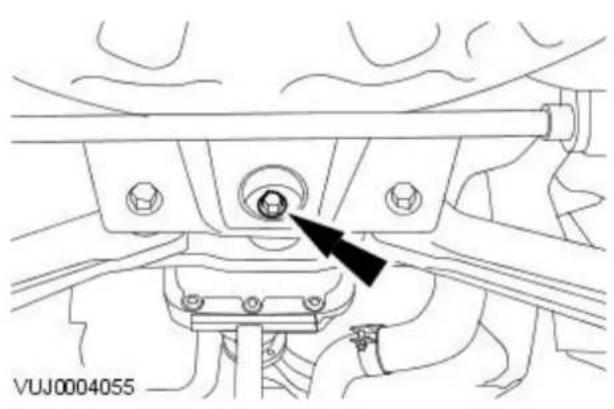
natural_image
Technical line drawing of a mechanical assembly with a black arrow pointing to a component (no text or symbols present)
natural_image
Technical diagram of a mechanical assembly with a black arrow pointing to a circular component (no text or symbols present)
natural_image
Technical diagram of a mechanical assembly with a circular component and an arrow indicating direction (no text or symbols present)

-
Tighten to 150 Nm.
-
CAUTION: Slowly tighten the axle retaining bolt to final torque. Failure to follow this instruction may result in damage to the vehicle.
Tighten to 150 Nm. If you are refitting an old fixing (before VIN J24258), tighten to 135 Nm.
-
Tighten to 40 Nm.
-
CAUTION: Support the driveshaft front and rear sections. Loosely install the driveshaft center bearing retaining bolts.
-
Attach the driveshaft front universal joint.
-
Install a new gasket.
- Install new driveshaft retaining bolts link washers.
- Install new driveshaft retaining bolts.
- Tighten to 40 Nm.
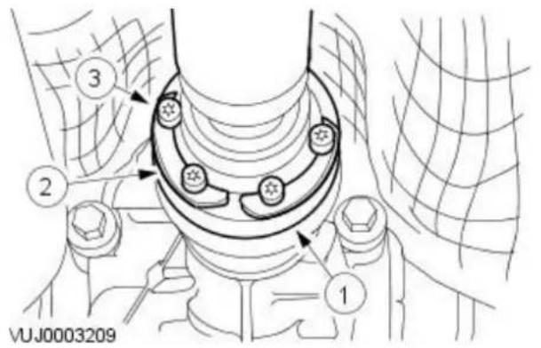


natural_image
Technical diagram of a car engine component with mounting holes and suspension parts (no text or labels)VUJ0004053
-
Attach the driveshaft rear universal joint.
-
Install a new gasket.
- Install new driveshaft retaining bolt link washers.
- Install new driveshaft retaining bolts.
-
Tighten to 40 Nm.
-
Carry out the under body misalignment check. For additional information, refer to: Underbody Misalignment Check (502-00 Uni-Body, Subframe and Mounting System, General Procedures).
-
Tighten to 25 Nm.
-
Remove the rear wheel knuckle retaining bolts.
-
Install the left-hand rear halfshaft. For additional information, refer to: Rear Halfshaft (205-05 Rear Drive Halfshafts, Removal and Installation).
Front Drive Halfshafts -
Published: 11-May-2011
| Torque Specifications | |||
| Description Nm lb-ft lb-in | |||
| Wheel hub nut 270 200 - | |||
| Tie rod end retaining nut 35 26 - | |||
| Lower arm ball joint retaining nut 83 61 - | |||
| Front subframe reinforcement plate retaining bolt 35 26 - | |||
| Front subframe rear mount retaining bolt 142 105 - | |||
| Front subframe front mount retaining bolt | 142 105 - | ||
| Transfer case Y bracket retaining bolt | 25 18 - | ||
| Intermediate shaft bearing carrier retaining bolts | 25 18 - | ||
| Front right-hand halfshaft retaining nuts - Vehicles with 2.0L or diesel engine | 25 18 - | ||
Front Drive Halfshafts - Front Drive Halfshafts
Description and Operation
Front Drive Halfshafts

VUJ0005086
| Item Part Number Description | |
| 1 — Outer constant velocity (CV) joint | |
| 2 — CV joint boot retaining clip | |
| 3 — CV joint boot | |
| 4 — CV joint boot retaining clip | |
| 5 — Snap ring | |
| 6 — Barshaft | |
| 7 — Circlip | |
| 8 — Tripod star | |
| 9 — Tripod star housing |
The front drive halfshafts are of equal lengths with the inner constant velocity (CV) joint being of the plunger type.
The inner and outer CV joints are linked by a solid barshaft. The inner CV joints are retained in the differential with the aid of a spring clip.
On vehicles with 2.0L or diesel engines there is an addition of an intermediate shaft which connects the right-hand side of the differential with the right-hand halfshaft. The right-hand halfshaft is retained in the intermediate shaft with the aid of a spring circlip. The intermediate shaft is supported by an additional bearing which is fitted to the outer end of the intermediate shaft and is attached to the right-hand catalytic converter retaining bracket.
Handling Front Drive Halfshafts
The following points should be observed when handling front drive halfshafts:
- Do not pull on the CV joints.
- Do not allow the CV joints to exceed 18 degrees of articulation.
- Check polished surfaces and splines for damage.
- Do not support the front drive halfshaft by holding the CV joint alone.
- Do not allow the CV joint boots to come into contact with sharp edges, hot vehicle components or the exhaust system.
- Do not drop the front drive halfshafts, this may cause damage to the interior of the boots which may not be visible.
Underbody Protection and Corrosion Prevention
The CV joint boots should be covered during application of underbody protection or corrosion prevention. Foreign matter on the CV boots may cause premature ageing of the material. Foreign material on the front drive halfshafts may cause imbalance.
Front Drive Halfshafts - Front Drive Halfshafts
Diagnosis and Testing
For additional information, refer to Section 205-00 Driveline System - General Information.
Front Drive Halfshafts - Front Halfshaft LH
Removal and Installation
| Special Tool(s) | |
| Ball joint splitter204-192 |
| 204-192 | |
 | Wheel hub puller205-491 |
| 205-491 | |
 | Adapter nuts205-491-01 |
| 20549101 | |
 | Forcing screw204-269 |
| 20 | |
 | Slide hammer100-012 |
| 100012 | |
 | 100-012-02Slide hammer shaft |
| 100-012-02 | |
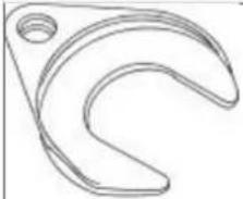 | Halfshaft remover fork204-226 |
| 204-226 | |
Removal
All vehicles
- Loosen the wheel hub nut.
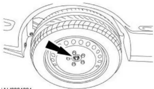
natural_image
Technical line drawing of a mechanical component with concentric rings and a central hub (no text or symbols)
natural_image
Mechanical assembly diagram showing a bolted joint with bolts and a black arrow pointing to a component (no text or symbols present)- Remove the front road wheel and tire. For additional information, refer to: Wheel and Tire (204-04 Wheels and Tires, Removal and Installation).
- Remove the tie rod end retaining nut.
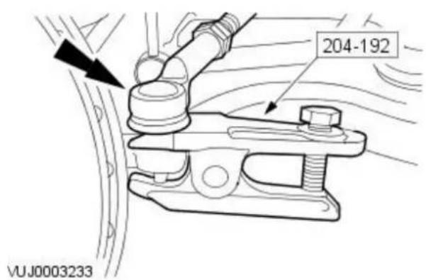
-
Using the special tool detach the tie rod end.
-
Remove the subframe reinforcement plate retaining bolts.

natural_image
Technical line drawing of a mechanical component with two black arrows pointing to features (no text or symbols present)- Loosen the subframe rear mount retaining bolt.

natural_image
Technical line drawing of a mechanical component with a black arrow indicating a directional movement (no text or symbols present)
natural_image
Technical line drawing of a mechanical component with a black arrow pointing to a circular feature (no text or symbols)- Loosen the subframe front mount retaining bolt.

natural_image
Technical line drawing of a vehicle brake system with no visible text or symbols- Remove and discard the wheel hub nut.
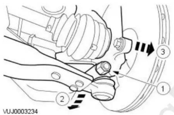
-
Detach the wheel knuckle.
-
Remove the lower arm ball joint retaining bolt.
- Reposition the lower arm.
- Detach the wheel knuckle.

- Using the special tools, detach the halfshaft.
Vehicle with automatic transmission
- Drain the automatic transmission fluid. For additional information, refer to: Transmission Fluid Drain and Refill (307-01B Automatic Transmission/Transaxle - Vehicles With: 6-Speed Automatic Transaxle - AWF21, General Procedures).
Vehicles with manual transmission
- Drain the manual transmission fluid. For additional information, refer to: Transaxle Draining and Filling - Vehicles With: 6-Speed Manual Transaxle - MMT6 (308-03 Manual Transmission/Transaxle, General Procedures).


natural_image
Technical line drawing of a mechanical assembly with no visible text or symbols-
Using the special tools, remove the halfshaft.
-
CAUTION: Use suitable protective covers to protect the barshaft. Remove the halfshaft snap ring.
Installation
All vehicles

natural_image
Technical line drawing of a mechanical assembly with no visible text or symbols- Install a new snap ring to the halfshaft.
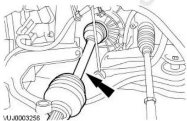
natural_image
Technical diagram of a vehicle suspension system showing shaft, bearings, and suspension components (no text or labels)- CALATION: Make sure the CV joint splines are located fully. Do not use excessive force when engaging the CV joint into the transmission. Install the halfshaft.

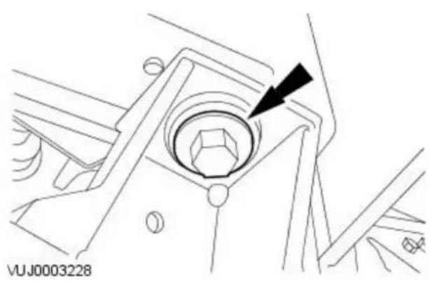
natural_image
Technical line drawing of a mechanical component with a central hexagonal feature and an arrow pointing to it (no text or symbols present)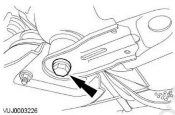
natural_image
Technical line drawing of a mechanical component with a black arrow indicating a specific part (no text or symbols present)
natural_image
Technical line drawing of a mechanical component with arrows pointing to features (no text or symbols)
natural_image
Technical line drawing of a mechanical component with a black arrow pointing to a feature (no text or symbols present)-
Attach the wheel knuckle.
-
Reposition the lower arm.
-
Attach the wheel knuckle.
-
Install the lower arm ball joint retaining bolt.
- Tighten to 83 Nm.
- Tighten the front subframe front mount retaining bolt.
- Tighten to 142 Nm.
-
Loosely install the subframe rear mount retaining bolt.
-
Install the subframe reinforcement plate retaining bolts.
- Tighten to 35 Nm.
- Tighten to 142 Nm.

natural_image
Mechanical assembly diagram showing a bolted joint with mounting brackets and a black arrow pointing to a component (no text or symbols present)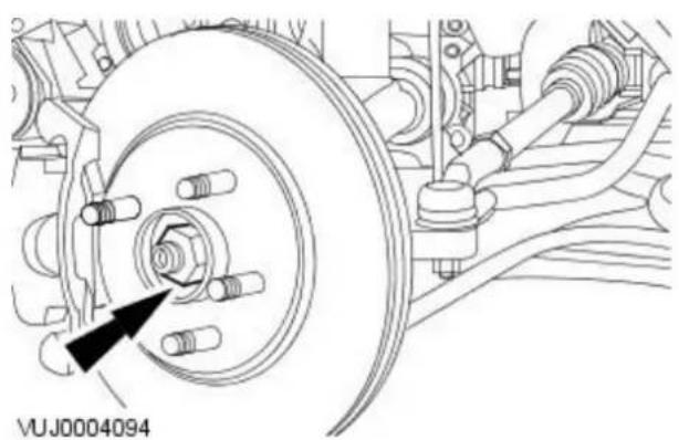
natural_image
Technical diagram of a vehicle brake system with a circular component and attached suspension components (no text or symbols)- Install the tie rod end.
- Tighten to 35 Nm.
-
Loosely install a new wheel hub nut.
-
Install the front road wheel and tire. For additional information, refer to: Wheel and Tire (204-04 Wheels and Tires, Removal and Installation).
Vehicle with automatic transmission
- Refill the automatic transmission system. For additional information, refer to: Transmission Fluid Drain and Refill (307-01B Automatic Transmission/Transaxle - Vehicles With: 6-Speed Automatic Transaxle - AWF21, General Procedures).
Vehicles with manual transmission
-
Refill the manual transmission system. For additional information, refer to: Transaxle Draining and Filling - Vehicles With: 6-Speed Manual Transaxle - MMT6 (308-03 Manual Transmission/Transaxle, General Procedures).
-
Tighten the wheel hub nut.
- Tighten to 270 Nm.

natural_image
Technical line drawing of a mechanical component with concentric rings and bolt holes, no text or symbols present.- Check the subframe alignment. For additional information, refer to: Underbody Misalignment Check (502-00 Uni-Body, Subframe and Mounting System, General Procedures).
Front Drive Halfshafts - Front Halfshaft RH2.0L NA V6 - AJV6/ 2.5L NA V6 - AJV6/ 3.0L NA V6 - AJ27
Removal and Installation
| Special Tool(s) | |
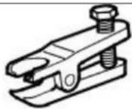 | Ball joint splitter204-192 |
| 204-192 | |
 | Wheel hub puller205-491 |
| 205-491 | |
 | Adapter nuts205-491-01 |
| 20549101 | |
 | Forcing screw204-269 |
| 20 | |
 | RH halfshaft splitter307-442 |
| 307-442 | |
 | RH halfshaft splitter handle307-443 |
| 307-442 | |
 | Slide hammer shaft100-012-02 |
| 100-012-02 | |
 | Slide hammer100-012 |
| 100012 | |
 | Halfshaft remover fork204-226 |
| 204-226 | |
All vehicles

natural_image
Technical line drawing of a mechanical component with concentric rings and a central hub, no text or symbols present.- Loosen the wheel hub nut.

natural_image
Technical line drawing of a mechanical assembly with no visible text or symbols-
Remove the front road wheel and tire. For additional information, refer to: Wheel and Tire (204-04 Wheels and Tires, Removal and Installation).
-
Remove the tie rod-end retaining nut.

- Using the special tool, detach the tie-rod end.
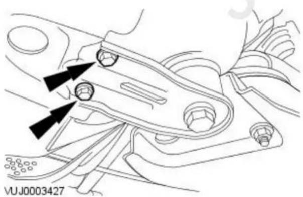
natural_image
Technical line drawing of a mechanical component with arrows indicating assembly or movement (no text or symbols)- Remove the subframe reinforcement plate retaining bolts.

natural_image
Technical line drawing of a mechanical component with no visible text or symbols- Loosen the subframe rear mount bolt.

natural_image
Technical line drawing of a mechanical component with a black arrow pointing to a central feature (no text or symbols)- Loosen the subframe front mount bolt.

natural_image
Technical line drawing of a vehicle suspension system with a circular component and bolted joints (no text or symbols)- Remove and discard the wheel hub nut.

-
Detach the wheel knuckle.
-
Remove the lower arm ball joint retaining bolt.
- Reposition the lower arm.
-
Detach the wheel knuckle.
-
Using the special tools, detach the halfshaft.

Vehicles with 2.5L or 3.0L engine

natural_image
Technical line drawing of a mechanical component with an arrow indicating a specific part (no text or symbols present)- Remove the exhaust muffler inlet pipe. For additional information, refer to: Muffler Inlet Pipe - 2.0L NA V6 - AJV6/2.5L NA V6 - AJV6/3.0L NA V6 - AJ27 (309-00 Exhaust System, Removal and Installation).
-
Remove the halfshaft seal.
-
Remove the transfer case Y bracket retaining bolt.

natural_image
Technical line drawing of a mechanical component with a black arrow pointing to a small component (no text or symbols present)- CAUTION: To prevent damage to the transfer box internal seal, make sure that the link shaft is not retracted further than 200 mm from the transfer box casing.

Using the special tools, remove the halfshaft.
- Attach special tools to the halfshaft.
- Lever the special tools to displace the halfshaft.
- Install the transfer case Y bracket retaining bolt.
- Remove the halfshaft.
Vehicles with 2.0L engine
- Remove the halfshaft.

natural_image
Technical diagram of a mechanical assembly with no visible text or symbolsAll vehicles

natural_image
Technical line drawing of a mechanical assembly with no visible text or symbols- CATION: Use suitable protective covers to protect the barshaft. Remove and discard the halfshaft snap ring.
Installation
All vehicles
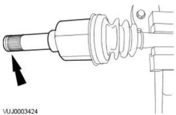
natural_image
Technical line drawing of a mechanical assembly with no visible text or symbols- Install a new snap ring to the halfshaft.
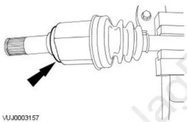
natural_image
Technical line drawing of a mechanical assembly with no visible text or symbols- Install a new halfshaft seal.
Vehicles with 2.0L engine
- Install the halfshaft.
- Tighten to 25 Nm.

natural_image
Technical diagram of a mechanical assembly with no visible text or symbolsVehicles with 2.5L or 3.0L engine
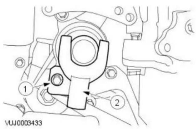

natural_image
Technical diagram of a vehicle belt switch component (no text or symbols visible)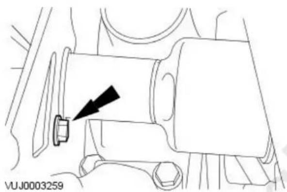
natural_image
Technical line drawing of a mechanical component with a black arrow pointing to a small component (no text or symbols present)-
Remove the special tool.
-
Remove the transfer case Y bracket retaining bolt.
-
Remove the special tool.
-
CAUTION: Make sure the CV joint splines are located fully. Do not use excessive force when engaging the CV joint into the link shaft.
Install the halfshaft.
- Install the transfer case Y bracket retaining bolt.
- Tighten to 25 Nm.
- Install the exhaust muffler inlet pipe. For additional information, refer to: Muffler Inlet Pipe - 2.0L NA V6 - AJV6/2.5L NA V6 - AJV6/3.0L NA V6 - AJ27 (309-00 Exhaust System, Removal and Installation).
-
Attach the wheel knuckle.
-
Reposition the lower arm.
- Attach the wheel knuckle.
- Install the lower arm ball joint retaining bolt.
- Tighten to 83 Nm.
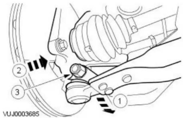
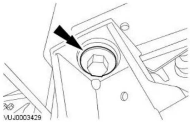
natural_image
Technical line drawing of a mechanical component with a black arrow pointing to a circular feature (no text or symbols)
natural_image
Technical line drawing of a mechanical component with two black arrows pointing to specific features (no text or symbols present)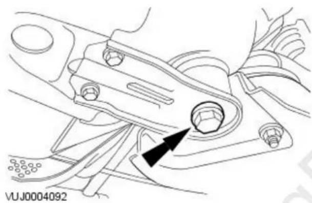
natural_image
Technical line drawing of a mechanical component with no visible text or symbols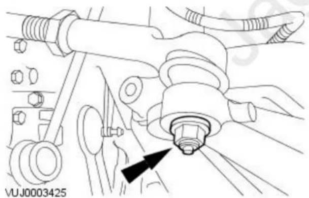
natural_image
Technical line drawing of a mechanical assembly with bolts and a bolt head (no text or symbols)
natural_image
Technical line drawing of a vehicle brake system with no visible text or symbols- Tighten the subframe front mount retaining bolt.
- Tighten to 142 Nm.
- Install the subframe reinforcement plate retaining bolts.
- Tighten to 35 Nm.
-
Tighten to 142 Nm.
-
Install the tie-rod end.
- Tighten to 35 Nm.
- Loosely install a new wheel hub nut.
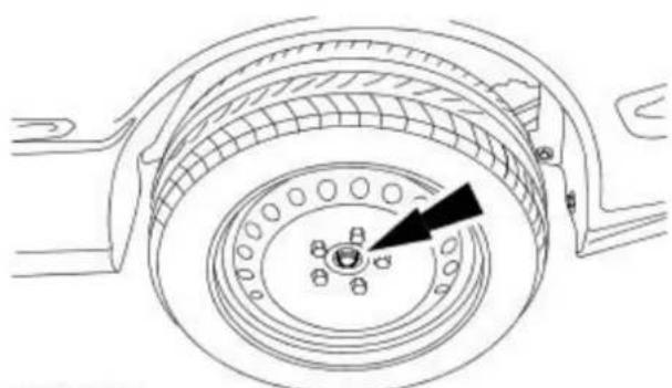
natural_image
Technical line drawing of a mechanical component with concentric rings and a central hub (no text or symbols)VUJ0004093
- Install the front road wheel and tire.
For additional information, refer to: Wheel and Tire (204-04 Wheels and Tires, Removal and Installation).
- Tighten the wheel hub nut.
- Tighten to 270 Nm.
- Check the subframe alignment.
For additional information, refer to: Underbody Misalignment Check (502-00 Uni-Body, Subframe and Mounting System, General Procedures).
Front Drive Halfshafts - Front Halfshaft RH2.0L Duratorq-TDCi/ 2.2L Duratorq-TDCi (110kW/ 150PS) - Puma
Removal and Installation
| Special Tool(s) | |
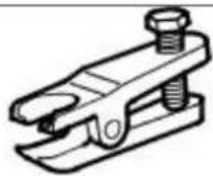 | Ball joint splitter204-192 |
| 204-192 | |
 | Wheel hub puller205-491 |
| 205-491 | |
 | Adapter nuts205-491-01 |
| 20549101 | |
 | Forcing screw204-269 |
Removal
- Loosen the wheel hub nut.

natural_image
Technical line drawing of a mechanical component with concentric rings and bolt holes, no text or symbols present.
natural_image
Technical line drawing of a mechanical assembly with no visible text or symbols- Remove the front road wheel and tire. For additional information, refer to: Wheel and Tire (204-04 Wheels and Tires, Removal and Installation).
- Remove the tie rod-end retaining nut.

- Using the special tool, detach the tie-rod end.

natural_image
Technical line drawing of a mechanical component with two black arrows pointing to features (no text or symbols present)- Remove the subframe reinforcement plate retaining bolts.
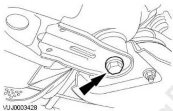
natural_image
Technical line drawing of a mechanical component with no visible text or symbols- Loosen the subframe rear mount bolt.
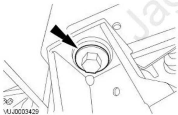
natural_image
Technical line drawing of a mechanical component with a bolt and arrow indicator (no readable text or symbols)- Loosen the subframe front mount bolt.
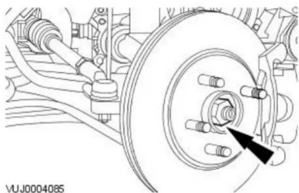
natural_image
Technical line drawing of a vehicle brake system with no visible text or symbols- Remove and discard the wheel hub nut.

-
Detach the wheel knuckle.
-
Remove the lower arm ball joint retaining bolt.
- Reposition the lower arm.
-
Detach the wheel knuckle.
-
Using the special tools, detach the halfshaft.
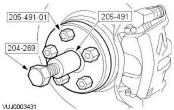
- Remove the halfshaft.
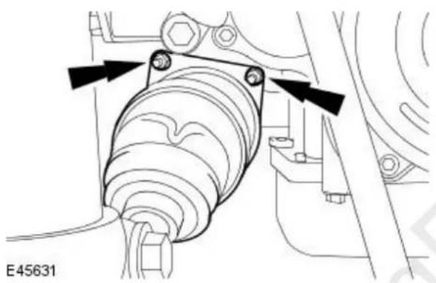
natural_image
Technical line drawing of a mechanical assembly with no visible text or symbols- CAUTION: Use suitable protective covers to protect the barshaft. Remove and discard the halfshaft snap ring.

natural_image
Technical line drawing of a mechanical assembly with no visible text or symbolsInstallation

natural_image
Technical line drawing of a mechanical assembly with no visible text or symbols
natural_image
Technical diagram of a mechanical assembly with no visible text or symbols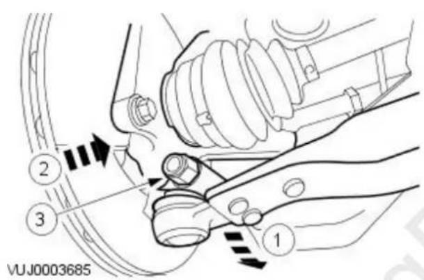

natural_image
Technical line drawing of a mechanical component with a bolt and arrow indicator (no readable text or symbols)
natural_image
Technical line drawing of a mechanical component with arrows pointing to features (no text or symbols)-
Install a new snap ring to the halfshaft.
-
Install the halfshaft.
- Tighten to 25 Nm.
-
Attach the wheel knuckle.
-
Reposition the lower arm.
-
Attach the wheel knuckle.
-
Install the lower arm ball joint retaining bolt.
- Tighten to 83 Nm.
- Tighten the subframe front mount retaining bolt.
- Tighten to 142 Nm.
- Install the subframe reinforcement plate retaining bolts.
- Tighten to 35 Nm.
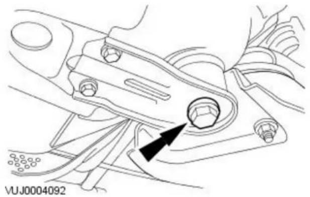
natural_image
Technical line drawing of a mechanical assembly with no visible text or symbols
natural_image
Technical line drawing of a mechanical assembly with no visible text or symbols
natural_image
Technical line drawing of a vehicle brake system with no visible text or symbols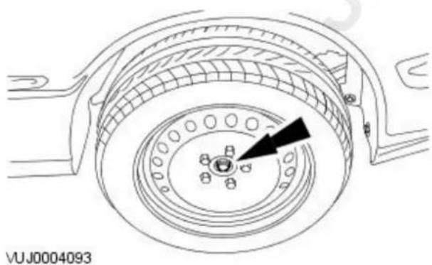
natural_image
Technical line drawing of a mechanical component with concentric rings and a central hub (no text or symbols)-
Tighten to 142 Nm.
-
Install the tie-rod end.
- Tighten to 35 Nm.
-
Loosely install a new wheel hub nut.
-
Install the front road wheel and tire. For additional information, refer to: Wheel and Tire (204-04 Wheels and Tires, Removal and Installation).
-
Tighten the wheel hub nut.
- Tighten to 270 Nm.
- Check the subframe alignment. For additional information, refer to: Underbody Misalignment Check (502-00 Uni-Body, Subframe and Mounting System, General Procedures).
Front Drive Halfshafts - Inner Constant Velocity (CV) Joint Boot
Removal and Installation
Removal
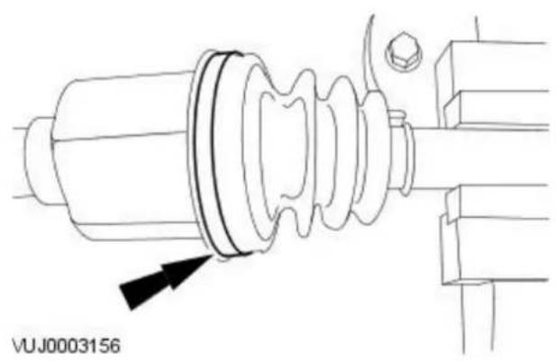
natural_image
Technical line drawing of a mechanical assembly with no visible text or symbols- Remove the front halfshaft. For additional information, refer to Halfshaft LH. For additional information, refer to Halfshaft RH.
- CAUTION: Use suitable protective covers to protect the barshaft.
Using a suitable clamp, secure the front halfshaft.
- Remove the inner constant velocity (CV) joint boot outer retaining clip.
- Remove and discard the retaining clip.

natural_image
Technical line drawing of a mechanical component with no visible text or symbols- Remove the tripod star housing.
- Remove and discard the grease.

natural_image
Technical line drawing of a mechanical component with a highlighted circular feature and arrow indicator (no text or symbols)- Remove the tripod star circlip.

natural_image
Technical line drawing of a mechanical component with a threaded end and spiral grooves (no text or symbols)- CAUTION: Do not damage the roller bearings.
Using a suitable brass drift, remove the tripod star.
VUJ0003159
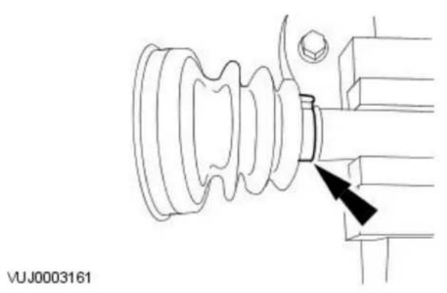
natural_image
Technical line drawing of a mechanical assembly with no visible text or symbols- Remove the inner CV joint boot retaining clip.
- Remove and discard the retaining clip.

natural_image
Technical line drawing of a mechanical component with no visible text or symbols- Remove the inner CV joint boot.
Installation

natural_image
Technical line drawing of a mechanical component with no visible text or symbols- Install the inner CV joint boot.
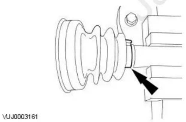
natural_image
Technical line drawing of an electrical insulator assembly with a black arrow pointing to a component (no text or symbols present)- NOTE: Install a new retaining clip.
Using a suitable tool, install the inner CV joint boot retaining clip.

-
CAUTION: Do not damage the roller bearings. Install the tripod star.
-
Install the tripod star circlip.
-
NOTE: Install new grease. Install the tripod star housing.
-
NOTE: Make sure enough air is present in the CV boot.
- NOTE: Install a new retaining clip.
Using a suitable tool, install the inner constant velocity (CV) joint boot outer retaining clip.
- Remove the front halfshaft from the clamp.
- Install the front halfshaft. For additional information, refer to Halfshaft LH. For additional information, refer to Halfshaft RH.
Front Drive Halfshafts - Intermediate Shaft
Removal and Installation
Removal
All vehicles
- Remove the right-hand halfshaft. For additional information, refer to Halfshaft RH in this section.
Vehicles with automatic transmission
- Drain the automatic transmission fluid. For additional information, refer to Section 307-01A Automatic Transmission/Transaxle / 307-01B Automatic Transmission/Transaxle.
Vehicles with manual transmission
- Drain the manual transmission fluid. For additional information, refer to Section 308-03 Manual Transmission/Transaxle.
All vehicles

natural_image
Technical line drawing of a mechanical component with arrows indicating assembly or adjustment points (no text or symbols present)- CAUTION: Before removing the bearing carrier retaining bolts, identify their correct position. Failure to follow this procedure will result in damage to the vehicle.
Remove the intermediate shaft bearing carrier retaining bolts.
- Remove the branch pipe heat shield.
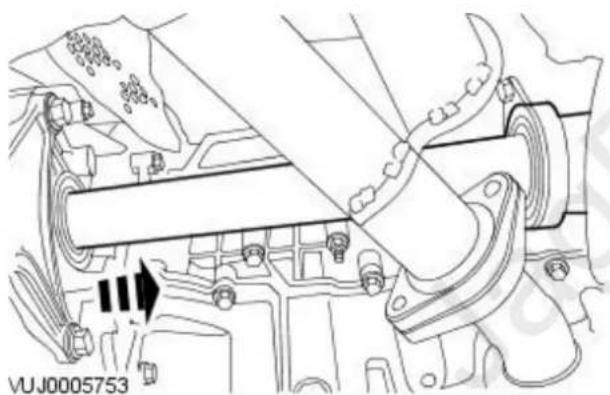
natural_image
Technical line drawing of a mechanical assembly with no visible text or symbols- Remove the intermediate shaft.
Installation
All vehicles

natural_image
Technical line drawing of a mechanical assembly with no visible text or symbols- CAUTION: Make sure the intermediate shaft splines are located fully. Do not use excessive force when engaging the intermediate shaft into the transmission.
Install the intermediate shaft.

natural_image
Technical line drawing of a mechanical component with arrows indicating assembly or adjustment points (no text or symbols present)- CAUTION: Before installing the bearing carrier retaining bolts make sure that the bearing carrier is located in the same position that it was removed from, failure to follow this procedure will result in damage to the vehicle.
Install the branch pipe heat shield.
- Tighten to 25 Nm.
Vehicles with automatic transmission
- Refill the automatic transmission system. For additional information, refer to Section 307-01A Automatic Transmission/Transaxle / 307-01B Automatic Transmission/Transaxle.
Vehicles with manual transmission
- Refill the manual transmission. For additional information, refer to Section 308-03 Manual Transmission/Transaxle.
All vehicles
- Install the right-hand halfshaft. For additional information, refer to Halfshaft RH in this section.
Front Drive Halfshafts - Outer Constant Velocity (CV) Joint Boot
Removal and Installation
Removal

natural_image
Technical line drawing of an electrical insulator assembly with threaded shaft and internal coil (no text or symbols)VUJ0003163

natural_image
Technical line drawing of an electrical insulator component with threaded shaft and threaded end (no text or symbols)VUJ0003164
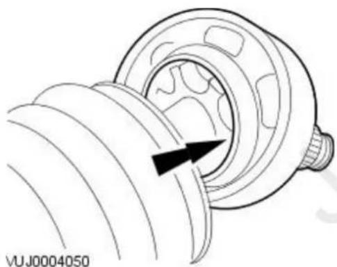
natural_image
Mechanical component diagram showing a rotating shaft and housing with a black arrow indicating direction (no text or symbols)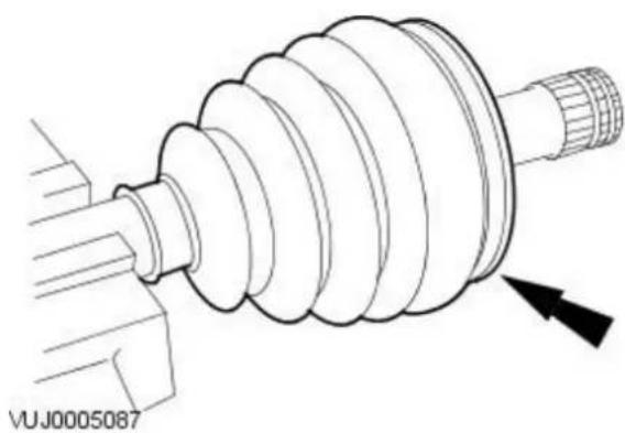
natural_image
Technical line drawing of a mechanical component with threaded end and internal spiral structure (no text or symbols)- Remove the front halfshaft. For additional information, refer to Halfshaft LH. For additional information, refer to Halfshaft RH.
- ⚫ TION: Use suitable protective covers to protect the barshaft. Using a suitable clamp, secure the front halfshaft
- Remove the outer constant velocity (CV) joint retaining clips.
- Remove and discard the retaining clips.
- Detach the outer CV joint boot.
- Remove and discard the grease.
- CAUTION: Do not damage the bearing retainer.
- NOTE: The outer CV joint is retained to the shaft by a spring clip. Using a suitable brass drift, remove the outer CV joint.
- Remove the outer CV joint boot.

natural_image
Technical line drawing of an insulator assembly with threaded shaft and housing (no text or symbols)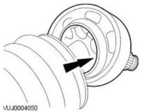
natural_image
Technical line drawing of a mechanical component with a black arrow indicating direction (no text or symbols)
natural_image
Technical line drawing of an electrical insulator component with threaded shaft and threaded end (no text or symbols)
natural_image
Technical line drawing of an electrical insulator assembly with threaded shaft and internal coil (no text or symbols)-
Install the outer CV joint boot.
-
CALITION: Do not damage the bearing retainer.
- NOTE: The outer CV joint is retained to the shaft by a spring clip. Install the outer CV joint.
- Attach the outer CV joint boot.
• Install new grease.
- NOTE: Make sure enough air is present in the CV boot.
- NOTE: Install new retaining clips.
Using a suitable tool, install the CV joint retaining clips.
- Remove the front halfshaft from the clamp.
- Install the front halfshaft. For additional information, refer to Halfshaft LH. For additional information, refer to Halfshaft RH.
Rear Drive Halfshafts -
Lubricants, Fluids, Sealers and Adhesives
| Item Specification | |
| Constant velocity (CV) grease Olistamoly LN 584 LO |
Fill Capacities
| Description Grams | |
| Grease for inner CV joint boot 90 | |
| Grease for inner CV joint 90 | |
| Grease for outer CV joint boot 90 | |
| Grease for outer CV joint 90 |
Rear Drive Halfshafts - Rear Drive Halfshafts
Description and Operation
Rear Drive Halfshafts

VUJ0003011
| Item Part Number Description | |
| 1 — Outer constant velocity (CV) joint | |
| 2 — Anti-lock brake system (ABS) ring | |
| 3 — Outer CV joint boot | |
| 4 — Inner CV joint boot | |
| 5 — Seal protector | |
| 6 — Spring clip | |
| 7 — Inner CV joint | |
| 8 — Barshaft |
The rear drive halfshafts are of unequal lengths and both the inner CV joint and outer CV joints are of the plunger type.
The outer CV joints are fitted with an ABS ring which is continuously monitored by the wheel speed sensor.
The inner and outer CV joints are linked by a solid barshaft. The inner CV joints are retained in the differential with the aid of a spring clip.
The inner CV joints are fitted with plastic seal protectors to protect the halfshaft oil seals located in the differential from debris.
Due to the unique construction of the rear drive halfshafts they are not a serviceable item. If a problem occurs the halfshaft must be replaced as a complete unit.
Handling Rear Drive Halfshafts
The following points should be observed when handling rear drive halfshafts:
- Do not pull on the CV joints
- Do not allow the CV joints to exceed 18 degrees of travel
- Check polished surfaces and splines for damage
- Do not allow the CV joint boots to come into contact with sharp edges, hot vehicle components or the exhaust system
- Do not drop the rear drive halfshafts, this may cause damage to the splined sections of the CV joints, the threaded sections of the CV joints or the interior of the boots which may not be visible
- Do not support the rear drive halfshaft by holding the CV joint alone
Underbody Protection and Corrosion Prevention
The CV joint boots should be covered during application of underbody protection or corrosion prevention. Foreign matter on the CV boots may cause premature ageing of the material. Foreign material on the rear drive halfshafts may cause imbalance.
Rear Drive Halfshafts - Rear Drive Halfshafts
Diagnosis and Testing
For additional information, refer to Section 205-00 Driveline System - General Information.
Rear Drive Halfshafts - Rear Halfshaft
Removal and Installation
| Special Tool(s) | |
| Remover, Axle Shaft Oil Seal308-208 | |
| Installer, Oil Seal204-264 | |

natural_image
Technical line drawing of a mechanical assembly with no visible text or symbols
Removal
- Remove the wheel knuckle. For additional information, refer to: Wheel Knuckle (204-02 Rear Suspension, Removal and Installation).
-
Remove the halfshaft.
-
Using the special tool, remove and discard the axle shaft oil seal.
Installation
- Using the special tool, install the axle shaft oil seal.


natural_image
Technical line drawing of a mechanical assembly with no visible text or symbols- NOTE: When installing the halfshaft make sure the spring clip is fully engaged in the differential.
Install the halfshaft.
- Install the wheel knuckle.
For additional information, refer to: Wheel Knuckle (204-02 Rear Suspension, Removal and Installation).
Rear Drive Halfshafts - Outer Constant Velocity (CV) Joint Boot
Removal and Installation
Removal
- NOTE: Outer Constant Velocity (CV) Joint Boot shown, inner Constant Velocity (CV) Joint Boot similar.

natural_image
Technical line drawing of a mechanical component with threaded shaft and gear-like structure (no text or symbols)- Remove the halfshaft.
For additional information, refer to: Rear Halfshaft (205-05 Rear Drive Halfshafts, Removal and Installation).
- CAUTION: Use suitable protective covers to protect the halfshaft.
Using a suitable clamp, secure the halfshaft.
- Remove the outer constant velocity (CV) joint boot retaining clip.
- Discard the retaining clip.

natural_image
Technical line drawing of a mechanical assembly with a gear and housing (no text or symbols)- CAUTION: Do not damage the bearing retainer.
- NOTE: The outer CV joint is retained to the shaft by a spring clip. Using a suitable brass drift, remove the outer CV joint.

natural_image
Technical line drawing of a mechanical component with a gear and shaft, showing internal structure without any text or symbols.- Remove the retaining clip.
- Discard the retaining clip.
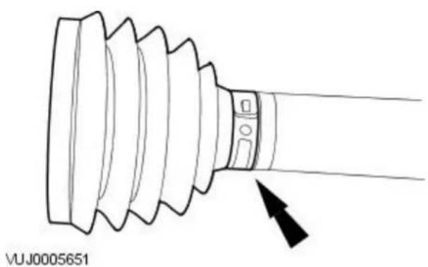
natural_image
Technical line drawing of a mechanical component with threaded ends and a pointed tip, no text or symbols present- Remove the outer CV joint boot.
- Discard the retaining clip.

natural_image
Technical line drawing of a mechanical component with a pointed tip and arrow indicator (no text or symbols)VUJ0005651
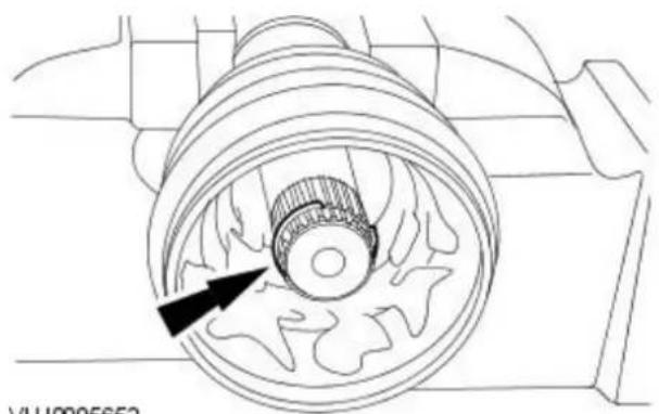
natural_image
Technical line drawing of a mechanical gear assembly with no visible text or symbolsVUJ0005652
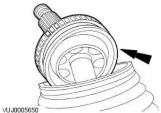
natural_image
Technical line drawing of a mechanical assembly with a gear and housing (no text or symbols)
natural_image
Technical line drawing of a mechanical gear assembly with threaded shaft and threaded end (no text or symbols)VUJ0005649
- Install the outer CV joint boot.
• Install a new retaining clip.
• Using a suitable tool, install the retaining clip.
- Install the new retaining clip.
• Install a new retaining clip.
• Using a suitable tool, install the retaining clip.

STION: Make sure the CV joint ball bearings do not drop out of joint.
• NOTE: Use a CV grease meeting Jaguar specification.
Install the outer CV joint.
- Fill the outer CV joint and outer CV gaitor with grease.
- Install the new retaining clip.
• Using a suitable tool, install the retaining clip.
- Remove the halfshaft from the clamp.
- Install the halfshaft.
For additional information, refer to: Rear Halfshaft (205-05 Rear Drive Halfshafts, Removal and Installation).
Brake System - General Information -
Lubricants, Fluids, Sealers and Adhesives

CAUTION: Do not use brake fluid ITT Super Dot 4 on 2006my vehicles onwards. Failure to follow this instruction may result in damage or vehicle.
- NOTE: Brake fluid ITT Super Dot 4 has now been superseded by Shell ESL Super Dot 4 which is the Jaguar recommended brake fluid. Shell ESL Super Dot 4 can be used on all model years.
| Item Specification | |
| Brake fluid ITT Super Dot 4 | |
| Brake fluid Shell ESL Super Dot 4 | |
| Caliper slide pin grease Klueber GLK1 |
Brake Lining and Disc Specifications
| Item Specification | |
| Brake pad nominal thickness - front 10.4 mm (0.40 in) | |
| Brake pad minimum thickness - front 2 mm (0.08 in) | |
| Brake pad nominal thickness - rear 11.80 mm (0.43 in) | |
| Brake pad minimum thickness - rear 2 mm (0.08 in) | |
| Brake disc diameter - front 300 mm (12 in) | |
| Brake disc diameter - rear 280 mm (11.032 in) | |
| New disc nominal thickness - front 24 mm (0.95 in) | |
| New disc nominal thickness - rear 12 mm (0.47 in) | |
| Worn disc discard thickness - front 22.2 mm (0.87 in) | |
| Worn disc discard thickness - rear 10.2 mm (0.40 in) | |
| Maximum disc runout (installed) - front | 0.076 mm (0.003 in) |
| Maximum hub face runout (installed) - front | 0.05 mm (0.002 in) |
| Maximum disc runout (installed) - rear | 0.076 mm (0.003 in) |
| Maximum hub face runout (installed) - rear | 0.05 mm (0.002 in) |
| Maximum thickness variation - new disc - front | 0.009 mm (0.0004 in) in 360° |
| Maximum thickness variation - new disc - rear | 0.009 mm (0.0004 in) in 360° |
| Caliper piston diameter -single piston - front | 57 mm (2.24 in) |
| Caliper piston diameter - rear | 38 mm (1.49 in) |
Brake System - General Information - Brake System
Description and Operation

WARNING: Brake fluid contains polyglycol ethers and polyglycols. Avoid contact with the eyes. Wash hands thoroughly after handling.
If brake fluid contacts the eyes, flush the eyes for 15 minutes with cold running water. Get medical attention if irritation persists. If taken internally, drink water and induce vomiting. Get medical attention immediately. Failure to follow these instructions may result in personal injury.
The braking system is a diagonally split, dual circuit design featuring front and rear disc brakes.
The hydraulic system provides separate circuits for each pair of diagonally opposed wheels (left front, right rear and right front, left rear).
The front calipers, mounted on the front knuckle, are single pistoned floating caliper design which make sure that equal effort is applied through both brake pads. The rear calipers are a single pistoned floating caliper design. The pads in all cases are asbestos free.
The parking brake control is located between the front seats and operates the rear brakes through a cable system. The cable has a manual adjust mechanism incorporated into the parking brake control.
The master cylinder is of a tandem design and is linked to a brake booster to reduce the brake pedal effort. On 2.0L variants a vacuum pump is fitted to ensure assistance in certain circumstances. The tandem design will make sure that in the event of one brake circuit failure the other will remain fully operational. The booster operating rod is connected directly to the brake pedal.
Brake System - General Information - Brake System
Diagnosis and Testing
Principles of Operations
The brake system operates by transferring effort applied to the brake pedal, by the driver, to the brakes at each wheel.
The braking effort is distributed to each wheel, using a hydraulic system. The system is assisted using a vacuum brake booster that reduces pedal effort for a given hydraulic pressure. The parking brake operates on the rear wheels and is applied using a hand operated control.
Inspection and Verification
- NOTE: Prior to carrying out any diagnosis, make sure that the brake system warning indicator is functional.
Visually examine the front and rear tire and wheel assemblies for damage such as uneven wear patterns, tread worn out or sidewall damage. Verify the tires are the same size, type and, where possible, same manufacture. Replace the damaged wheel or excessively worn tire. For additional information, refer to
REFER to: Wheel and Tire (204-04 Wheels and Tires, Removal and Installation).
Wheels and tires must be cleared of any foreign matter and tire pressures adjusted to the correct specification.
If the tires exhibit uneven wear or feathering, the cause must be corrected. Check the steering and suspension components for damage or wear, if necessary check and adjust the front wheel alignment. For additional information, refer to
REFER to: Front Toe Adjustment (204-00 Suspension System - General Information, General Procedures).
Road Test
Visual Inspection Chart
| Mechanical Electrical | |
| Brake master cylinder Parking brake switch | |
| Brake caliper piston(s) Damaged or corroded wiring harness | |
| Brake discs Brake master cylinder fluid level switch | |
| Wheel bearings Vacuum pump controller | |
| Brake pads Pedal box switches | |
| Power brake booster | |
| Brake pedal linkage | |
| Booster vacuum hose | |
| Tires | |
| Debris | |
| Modulator | |
| Vacuum pump | |
Carry out a road test to compare actual vehicle braking performance with the performance standards expected by the driver. The ability of the test driver to make valid comparisons and detect performance deficiencies will depend on experience.
The driver should have a thorough knowledge of brake system operation and accepted general performance guidelines to make good comparisons and detect performance concerns.
An experienced brake technician will always establish a route that will be used for all brake diagnosis road tests. The roads selected will be reasonably smooth and level. Gravel or bumpy roads are not suitable because the surface does not allow the tires to grip the road equally. Crowned roads should be avoided because of the large amount of weight shifted to the low set of wheels on this type of road. Once the route is established and consistently used, the road surface variable can be eliminated from the test results.
Before a road test, obtain a complete description of the customer concerns or suspected condition. From the description, the technician's experience will allow the technician to match possible causes with symptoms. Certain components will be tagged as possible suspects while others will be eliminated by the evidence. More importantly, the customer description can reveal unsafe conditions which should be checked or corrected before the road test. The description will also help form the basic approach to the road test by narrowing the concern to specific components, vehicle speed or conditions.
Begin the road test with a general brake performance check. Keeping the description of the concern in mind, test the brakes at different vehicle speeds using both light and heavy pedal pressure. To determine if the concern is in the front or rear braking system, use the brake pedal and then use the parking brake control. If the condition (pull, vibration, pulsation) occurs only with the parking brake, the concern is in the rear brake system.
If the concern becomes evident during this check, verify it fits the description given before the road test. If the concern is not evident, attempt to duplicate the condition using the information from the description.
If a concern exists, use the Symptom Chart in order to isolate it to a specific sub-system and condition description. From this description, a list of possible sources can be used to further narrow the cause to a specific component or condition.
Symptom Chart
| Symptom Possible Sources Action | ||
| Brakes noisy Brake pads. | * Brake discs. | * GO to Pinpoint Test A. |
| Vibration when brakes are applied | * Wheels require balancing. * Wheel hub nuts. * Caliper mounting bolts. * Brake pads. * Foreign material/scratches /corrosion on brake disc contact surfaces. * Excessive brake disc thickness variation. * Excessive brake disc runout. * Wheel bearing wear or failure. * Suspension bush wear or failure. * Steering bush wear or failure. | * Go to Pinpoint Test B. |
| The brakes pull or drift Tire pressures/wear.Calipers.Brake pads.Brake discs.Wheel alignment adjustment.Wheel bearing.Suspension bushes and ball joints. | * GO to Pinpoint Test C. |
| The pedal feels spongy Air in brake system.Leak in hydraulic system.Brake booster/master cylinder.Brake pads. | * GO to Pinpoint Test D. |
| The pedal goes down fast | * Air in brake system.Leak in hydraulic system.Brake booster/master cylinder.Brake pads. |
| The pedal goes down slowly | * Air in brake system.Brake booster/master cylinder. |
| Excessive brake pedal effort | * Brake pads.Brake booster.Vacuum pump. |
| Brake lockup during light brake pedal force | * Brake pads.Calipers. |
| Brakes drag Parking brake control applied/malfunction.Seized parking brake cables.Seized caliper slide pins.Seized caliper.Brake booster.Pedal gear. | * GO to Pinpoint Test I. |
| Excessive/Erratic brake pedal travel | * Hydraulic system.Brake pads.Brake discs.Hub and bearing assembly. |
| The red brake warning indicator is always on | * Fluid level. FILL the system to specification. CHECK for leaks. |
| * Brake fluid level sensor. INSTALL a new brake master cylinder fluid reservoir. For additional information, refer toREFER to: Brake Master Cylinder (206-06 Hydraulic Brake Actuation,Removal and Installation). | |
| * Parking brake control. RELEASE and ADJUST the parking brake. For additional information, refer toREFER to: Parking Brake Cable Adjustment - Vehicles With: ManuallyAdjusted Parking Brake, VIN Range: D55322->E24053 (206-05 Parking Brake and Actuation, General Procedures). | |
| * Electrical circuit. For additional information, refer to the approved Jaguar diagnostic system for analysis/rectification of the concern. | |
| Slow or incomplete brake pedal return | * Brake pedal binding.Brake booster/master cylinder. |
| PINPOINT TEST A : BRAKES NOISY | |
| TEST CONDITIONS DETAILS/ RESULTS/ ACTIONS | |
| A1: INSPECT BRAKE PADS | |
| 1 Inspect the condition of the front and rear brake pads. Check for damage to any anti-squeal shims. | |
| Are the brake pads OK?YesGO to A2.NoCLEAN the front brake pads or INSTALL new front brake pads if necessary. For additional information, refer toREFER to:Brake Pads(206-03 Front Disc Brake, Removal and Installation).CLEAN the rear brake pads or INSTALL new rear brake pads if necessary. For additional information, refer toREFER to:Brake Pads(206-04 Rear Disc Brake, Removal and Installation).Test vehicle for presence of brake squeal. | |
| A2: INSPECT BRAKE DISCS | |
| 1 Inspect the brake discs for excessive corrosion, wear or disc thickness variation. | |
| Does excessive corrosion, wear or disc thickness variation exist?YesINSTALL new front brake discs and brake pads. For additional information, refer toREFER to:Brake Disc(206-03 Front Disc Brake, Removal and Installation).INSTALL new rear brake discs and brake pads. For additional information, refer toREFER to:Brake Disc(206-04 Rear Disc Brake, Removal and Installation).TEST the system for normal operation.NoVehicle is OK. | |
| PINPOINT TEST B : VIBRATION WHEN BRAKES ARE APPLIED | |
| TEST CONDITIONS | DETAILS/ RESULTS/ ACTIONS |
| B1: ROAD TEST VEHICLE | |
| 1 Road test the vehicle between 40-80 km/h (25-50 mph) without applying brakes. | |
| Is the vibration present?YesTEST for noise vibration and harshness. For additional information, refer toREFER to: Noise, Vibration and Harshness (NVH) (100-04 Noise, Vibration and Harshness, Diagnosis and Testing).REPEAT road test if necessary.NoGO to B2. | |
| B2: CHECK FOR BRAKE VIBRATION | |
| 1 Road test the vehicle between 40-80 km/h (25-50 mph) with light and medium application on the brake pedal. | |
| Is a vibration present?YesCHECK the brake caliper mounting bolts and wheel hub nuts and TIGHTEN as necessary. CHECK the balance of all road wheels and REPAIR as necessary. CHECK the brake discs for excessive wear, runout, thickness variation or cracks. For additional information refer toREFER to:Front Disc Brake(206-03 Front Disc Brake, Diagnosis and Testing).INSTALL new brake discs and brake pads as necessary.GO to B3.NoVehicle is OK. | |
| B3: IS VIBRATION STILL PRESENT UNDER BRAKE APPLICATION? | |
| 1 Road test the vehicle between 40-80 km/h (25-50 mph) with light and medium application on the brake pedal. | |
| Is a vibration present?YesCHECK for wear or failure of steering bushes. For additional information, refer toREFER to:Power Steering(211-02 Power Steering, Diagnosis and Testing).CHECK for wear or failure of steering ball joints. For additional information, refer toREFER to:Steering Linkage(211-03 Steering Linkage, Diagnosis and Testing).CHECK for wear or failure of front wheel bearings, suspension bushes and ball joints. For additional information, refer toREFER to:Front Suspension(204-01 Front Suspension, Diagnosis and Testing).CHECK for wear or failure of rear wheel bearings, suspension bushes and ball joints. For additional information, refer toREFER to:Rear Suspension(204-02 Rear Suspension, Diagnosis and Testing).NoVehicle is OK. | |
| PINPOINT TEST C : THE BRAKES PULL OR DRI FT | |
| TEST CONDITIONS DETAILS/ RESULTS/ ACTIONS | |
| C1: ROAD TEST VEHICLE | |
| 1 Road test the vehicle and apply the brake pedal. | |
| Does the vehicle pull or drift?YesGO to C2.NoVehicle is OK. | |
| C2: INSPECT TI RE PRESSURE | |
| 1 Check for excessive tire wear or incorrect pressures. | |
| Are the tires at the correct pressure and in good condition?YesGO to C3.NoADJUST the tire pressures or INSTALL new tires if excessively worn. TEST the system for normal operation. | |
| C3: CHECK CALIPERS | |
| 1 Check the front caliper pistons for binding, leaking or sticking. For additional information, refer toREFER to:Front Disc Brake(206-03 Front Disc Brake, Diagnosis and Testing).Check the rear caliper pistons for binding, leaking or sticking. For additional information, refer toREFER to:Rear Disc Brake(206-04 Rear Disc Brake, Diagnosis and Testing). | |
| Do the disc brake caliper pistons and pins bind, leak or stick?YesINSTALL new calipers as necessary. TEST the system for normal operation.NoGO to C4. | |
| C4: INSPECT BRAKE DI SCS | |
| 1 Check the brake discs for excessive damage, thickness variation or runout. For additional information, refer toREFER to:Front Disc Brake(206-03 Front Disc Brake, Diagnosis and Testing). | |
| Does excessive damage or runout exist?YesINSTALL new brake discs and brake pads as necessary.TEST the system for normal operation.NoGO to C5. | |
| C5: INSPECT THE FRONT HUB AND WHEEL BEARING ASSEMBLY | |
| 1 Check the front hub and wheel bearing assembly. For additional information, refer toREFER to:Wheel Bearing Inspection(204-00 Suspension System - General Information, General Procedures). | |
| Are the wheel bearings OK?YesGO to C6.NoINSTALL new wheel bearings. For additional information, refer toREFER to:Front Wheel Bearing and Wheel Hub(204-01 Front Suspension, Removal and Installation).TEST the system for normal operation. | |
| C6: CHECK SUSPENSION BUSHES AND BALL JOINTS. | |
| 1 Check all suspension bushes and ball joints. | |
| Are the suspension bushes and ball joints OK?YesGO to C7.NoINSTALL new front suspension bushes and ball joints as required. For additional information, refer toREFER to:Front Stabilizer Bar Bushing(204-01 Front Suspension, Removal and Installation).INSTALL new rear suspension bushes and ball joints as required. For additional information, refer toREFER to:Rear Lower Arm(204-02 Rear Suspension, Removal and Installation). | |
| C7: CHECK VEHICLE ALIGNMENT | |
| 1 Check the vehicle alignment. For additional information, refer toREFER to:Underbody Misalignment Check(502-00 Uni-Body, Subframe and Mounting System, General Procedures). | |
| Is the alignment within specification?YesVehicle is OK.NoAdjust the alignment as necessary. For additional information, refer toREFER to:Underbody Misalignment Check(502-00 Uni-Body, Subframe and Mounting System, General Procedures). | |
| PINPOINT TEST D : THE PEDAL FEELS SPONGY | |
| TEST CONDITIONS | DETAILS/ RESULTS/ ACTIONS |
| D1: CHECK FOR SPONGY PEDAL (IGNITION OFF) | |
| 1 Check for a firm brake pedal. | |
| Is the brake pedal effort and brake pedal travel normal?YesVehicle is OK.NoGO to D2. | |
| D2: CHECK BRAKE PEDAL RESERVE (IGNITION OFF) | |
| 1 Pump the brake pedal 10 times and hold on the final application. | |
| Does the brake pedal feel firm on final application?YesGO to D3.NoBLEED the brake system. For additional information, refer toREFER to: Brake System Bleeding (206-00 Brake System - General Information, General Procedures).TEST the system for normal operation. | |
| D3: CHECK BRAKE PEDAL RESERVE (ENGINE ON) | |
| 1 Engine is idle. | |
| 2 Apply the brake pedal lightly three or four times. | |
| 3 Wait 15 seconds for the vacuum to recover. | |
| 4 Push down on the brake pedal until it stops moving downward or an increased resistance to the brake pedal travel occurs. | |
| 5 Hold the brake pedal in the applied position while increasing the engine speed to 2000 revs/min. | |
| 6 Release the accelerator pedal. | |
| Does the brake pedal move downward as the engine speed returns to idle?YesGO to D4.NoCHECK the vacuum to brake booster. For additional information, refer toREFER to: Brake Booster - RHD AWD/RHD FWD (206-07 Power Brake Actuation, Removal and Installation). | |
| D4: CHECK BRAKE FLUID LEVEL | |
| 1 Check the brake master cylinder reservoir fluid level. | |
| Is the fluid level OK?YesBLEED the brake system. For additional information, refer toREFER to: Brake System Bleeding (206-00 Brake System - General Information, General Procedures).TEST the system for normal operation.NoCHECK the brake master cylinder reservoir sealing points. For additional information, refer to Brake Master Cylinder Component Test in this section. ADD fluid and BLEED the brake system. For additional information, refer toREFER to: Brake System Bleeding (206-00 Brake System - General Information, General Procedures).TEST the system for normal operation. REPEAT road test if necessary. | |
| PINPOINT TEST E : THE PEDAL GOES DOWN FAST | |
| TEST CONDITIONS | DETAILS/ RESULTS/ ACTIONS |
| E1: ROAD TEST VEHICLE | |
| 1 Road test and apply the brake pedal. | |
| Is the brake pedal effort and brake pedal travel normal?Yes Vehicle is OK.No GO to E2. | |
| E2: CHECK BRAKE FLUID LEVEL | |
| 1 Check the brake master cylinder reservoir fluid level. | |
| Is the fluid level within specification?Yes GO to E3.No CHECK the brake master cylinder reservoir sealing points. For additional information, refer to Brake Master Cylinder Component Test in this section. ADD fluid and BLEED the brake system. For additional information, refer toREFER to: Brake System Bleeding (206-00 Brake System - General Information, General Procedures). .TEST the system for normal operation. REPEAT road test if necessary. | |
| E3: CHECK BRAKE PEDAL TRAVEL-PRESSURIZE SYSTEM (IGNITION OFF) | |
| 1 Pump the brake pedal rapidly (five times). | |
| Does the brake pedal travel build up and then hold?Yes BLEED the brake system. Refer toREFER to: Brake System Bleeding (206-00 Brake System - General Information, General Procedures). .TEST the system for normal operation. REPEAT road test. For additional information, refer toREFER to: Hydraulic Brake Actuation (206-06 Hydraulic Brake Actuation, Diagnosis and Testing).No GO to E4. | |
| E4: CHECK FOR BRAKE SYSTEM LEAKS | |
E4: CHECK FOR BRAKE SYSTEM LEAKS
| 1 Check for external brake system leaks. For additional information, refer to Master Cylinder in this section. | |
| Are leaks found?YesREPAIR as necessary, ADD fluid and BLEED brake system. For additional information, refer toREFER to: Brake System Bleeding (206-00 Brake System - General Information, General Procedures).TEST the system for normal operation. REPEAT road test.NoSystem is OK. |
| PINPOINT TEST F : THE PEDAL GOES DOWN SLOWLY | |
| TEST CONDITIONS | DETAILS/ RESULTS/ ACTIONS |
| F1: ROAD TEST VEHICLE - CHECK BRAKE PEDAL OPERATION | |
| Check if the condition occurs during actual stopping application by applying the brake pedal while the vehicle is moving. | |
| Does the condition occur when the vehicle is moving?YesGO to F2.NoGO to F3. | |
| F2: CHECK FOR BRAKE SYSTEM LEAKS | |
| Check for external brake system leaks. For additional information, refer to Master Cylinder in this section. | |
| Are there any external brake system leaks?YesREPAIR as necessary. ADD fluid and BLEED the brake system. For additional information, refer toREFER to: Brake System Bleeding (206-00 Brake System - General Information, General Procedures).TEST the system for normal operation.NoGO to F3. | |
| F3: CARRY OUT A BRAKE MASTER CYLINDER BYPASS TEST | |
| Test for brake master cylinder bypass condition. Refer to Brake Master Cylinder Component Test in this section. | |
| Are any concerns found?YesINSTALL a new brake master cylinder, ADD fluid and BLEED the brake system. For additional information, refer toREFER to: Brake System Bleeding (206-00 Brake System - General Information, General Procedures).TEST the system for normal operation.NoSystem is OK. | |
| PINPOINT TEST G : EXCESSIVE BRAKE PEDAL EFFORT | |
| TEST CONDITIONS | DETAILS/ RESULTS/ ACTIONS |
| G1: CHECK BRAKE PADS | |
| 1 Check the brake pads for wear, contamination, correct installation, damage and type. | |
| Are any concerns found?YesINSTALL the front brake pads correctly or INSTALL new front brake pads if necessary. For additional information, refer toREFER to:Brake Pads(206-03 Front Disc Brake, Removal and Installation).INSTALL the rear brake pads correctly or INSTALL new rear brake pads if necessary. For additional information, refer toREFER to:Brake Pads(206-04 Rear Disc Brake, Removal and Installation).REPEAT road test.NoGO to G2. | |
| G2: CHECK VACUUM | |
| 1 Disconnect the vacuum booster hose from the booster. | |
| 2 Connect a vacuum/pressure tester to the vacuum hose. | |
| 3 Run the engine at normal operating temperature. | |
| 4 Record the vacuum reading. | |
| Is the reading 40.5kPa (12 in-Hg) or greater?YesGO to G3.NoLOCATE and REPAIR the source of low vacuum. TEST the system for normal operation. | |
| G3: INSPECT SYSTEM | |
| 1 Switch the engine off. | |
| 2 Reconnect the vacuum hose. | |
| 3 Inspect the brake booster, rubber grommet and all vacuum plumbing for cracks, holes, damaged connections or missing clamps. | |
| 4 Pump the brake pedal several times to release the vacuum. Push down on the brake pedal and hold. | |
| Does the brake pedal move down when the engine is started?YesVacuum system is OK.NoGO to G4. | |
| G4: CHECK POWER BRAKE BOOSTER VALVE | |
| 1 Check the brake booster and vacuum pump valves. For additional information, refer to Brake Booster in this section. | |
| Is the power brake booster and vacuum pump valve OK?YesCHECK the brake booster. For additional information, refer to Brake Booster in this section. INSTALL a new brake booster if necessary. TEST the system for normal operation.NoINSTALL a new brake booster valve and vacuum pump valve. TEST the system for normal operation. | |
| TEST CONDITIONS | DETAILS/ RESULTS/ ACTIONS |
| H1: TEST BRAKE LOCKUP | |
| 1 Road test the vehicle and apply the brake pedal lightly. | |
| Do the brakes lockup?YesGO to H2.No Vehicle is OK. | |
| H2: INSPECT BRAKE PADS | |
| 1 Inspect brake pads for contamination, correct installation, damage and type. | |
| Are any concerns found?YesCHECK the front brake pads. For additional information, refer toREFER to: Front Disc Brake (206-03 Front Disc Brake, Description and Operation).CHECK the rear brake pads. For additional information, refer toREFER to: Rear Disc Brake (206-04 Rear Disc Brake, Description and Operation).INSTALL new brake pads as necessary.REPEAT road test.No GO to H3. | |
| H3: INSPECT BRAKE CALIPERS | |
| 1 Inspect brake calipers for binding, leaking or sticking. | |
| Are any concerns found?YesCHECK the front brake calipers. For additional information, refer toREFER to: Front Disc Brake (206-03 Front Disc Brake, Diagnosis and Testing).CHECK the rear brake calipers. For additional information, refer toREFER to: Rear Disc Brake (206-04 Rear Disc Brake, Diagnosis and Testing).INSTALL the brake calipers correctly or INSTALL new brake calipers as necessary. TEST the system for normal operation. REPEAT road test if necessary.No Vehicle is OK. | |
| PINPOINT TEST I : BRAKES DRAG | |
| TEST CONDITIONS DETAILS/ RESULTS/ ACTIONS | |
| I1: ROAD TEST VEHICLE | |
| 1 Road test the vehicle and apply the brakes. | |
| Are the brakes functioning correctly?Yes Vehicle is OK.No GO to 12. | |
| I2: CHECK CALIPERS | |
| 1 Check the front caliper pistons for binding, leaking or sticking. For additional information, refer toREFER to: Front Disc Brake (206-03 Front Disc Brake, Diagnosis and Testing).Check the rear caliper pistons for binding, leaking or sticking. For additional information, refer toREFER to: Rear Disc Brake (206-04 Rear Disc Brake, Diagnosis and Testing). | |
| Do the disc brake caliper pistons and pins bind, leak or stick?Yes INSPECT the brake calipers and parking brake cables. INSTALL new components as necessary. Road test vehicle.No GO to 13. | |
| I3: CHECK BRAKE BOOSTER | |
| 1 Check the brake booster connecting rod alignment and travel. For additional information, refer toREFER to: Power Brake System (206-07 Power Brake Actuation, Diagnosis and Testing). | |
| Is the connecting rod OK?Yes Vehicle is OK.No INSTALL a new brake booster. For additional information, refer toREFER to: Brake Booster - RHD AWD/RHD FWD (206-07 Power Brake Actuation, Removal and Installation).TEST the system for normal operation. | |
| PINPOINT TEST J: EXCESSIVE/ ERRATIC BRAKE PEDAL TRAVEL | |
| TEST CONDITIONS | DETAILS/ RESULTS/ ACTIONS |
| J1: TEST ON ROUGH ROAD | |
| 1 Road test the vehicle on rough road conditions. | |
| 2 Apply the brakes slowly. | |
| Is the brake pedal effort and brake pedal travel normal?Yes Vehicle is OK.No GO to J2. | |
| J2: CHECK BRAKE FLUID LEVEL | |
| 1 Check the brake master cylinder reservoir fluid level. | |
| Is the fluid level OK?Yes GO to J3.No CHECK brake master cylinder reservoir sealing points. For additional information, refer to Brake Master Cylinder in this section. ADD brake fluid and BLEED the brake system. For additional information, refer toREFER to: Brake System Bleeding (206-00 Brake System - General Information, General Procedures). .TEST the system for normal operation. REPEAT road test if necessary. | |
| J3: CHECK BRAKE PEDAL RESERVE | |
| 1 Engine is idle. | |
| 2 Apply the brake pedal lightly three or four times. | |
| 3 Wait 15 seconds for the vacuum to replenish. | |
| 4 Push down on the brake pedal until it stops moving downward or an increased resistance to the brake pedal travel occurs. | |
| 5 Hold the brake pedal in the applied position while increasing the engine speed to 2000 revs/min. | |
| 6 Release the accelerator pedal. | |
| Does the brake pedal move downward as the engine speed returns to idle?YesGO to J4.NoCHECK the vacuum to the brake booster. For additional information, refer toREFER to:Power Brake System(206-07 Power Brake Actuation, Diagnosis and Testing). | |
| J4: CHECK THE FRONT HUB AND BEARING ASSEMBLY | |
| 1 Check the front hub and bearing assembly. For additional information, refer toREFER to:Front Suspension(204-01 Front Suspension, Diagnosis and Testing). | |
| Are the front wheel bearings loose?YesINSTALL a new front wheel bearing if damaged. For additional information, refer toREFER to:Front Wheel Bearing and Wheel Hub(204-01 Front Suspension, Removal and Installation).TEST the system for normal operation.NoCHECK the front brake discs for thickness variances. For additional information, refer toREFER to:Brake Disc Runout Check(206-00 Brake System - General Information, General Procedures). | |
| PINPOINT TEST K : SLOW OR INCOMPLETE BRAKE PEDAL RETURN | |
| TEST CONDITIONS | DETAILS/ RESULTS/ ACTIONS |
| K1: CHECK FOR BRAKE PEDAL RETURN | |
| 1 Run the engine at fast idle while making several brake applications. | |
| 2 Pull the brake pedal rearward with approximately 44 N force. | |
| 3 Release the brake pedal and measure the distance to the toe board. | |
| 4 Make a hard brake application. | |
| 5 Release the brake pedal and measure the brake pedal to toe board distance. The brake pedal should return to its original position. | |
| Does the brake pedal return to its original position?Yes Vehicle is OK.No GO to K2. | |
| K2: CHECK FOR BRAKE PEDAL BINDING | |
| 1 Check the brake pedal to make sure it is operating OK. | |
| Is the brake pedal operating OK?Yes INSTALL a new brake booster. For additional information, refer toREFER to: Brake Booster - RHD AWD/RHD FWD (206-07 Power Brake Actuation, Removal and Installation).TEST the system for normal operation.No REPAIR or INSTALL new brake pedal. TEST the system for normal operation. | |
Component Tests
Brake Booster
- Check all hoses and connections. All unused vacuum connectors should be capped. Hoses and their connections should be correctly secured and in good condition with no holes and no collapsed areas. Inspect the valve on the brake booster for damage.
- Check the hydraulic brake system for leaks or low fluid.2.
-
- With the transmission in PARK (automatic transmissions) or in NEUTRAL (manual transmissions), stop the engine and apply the parking brake. Pump the brake pedal several times to exhaust all vacuum in the system.
-
- With the engine switched off and all vacuum in the system exhausted, apply the brake pedal and hold it down. Start the engine. If the vacuum system is operating, the brake pedal will tend to move downward under constant foot pressure. If no motion is felt, the vacuum booster system is not functioning.
- Remove the vacuum hose from the brake booster. Manifold vacuum should be available at the brake booster end of the hose with the engine at idle speed and the transmission in PARK or NEUTRAL. Make sure that all unused vacuum outlets are correctly capped, hose connectors are correctly secured and vacuum hoses are in good condition. When it is established that manifold vacuum is available to the brake booster, connect the vacuum hose to the brake booster and repeat Step 3. If no downward movement of the brake pedal is felt, install a new brake booster.
-
- Operate the engine for a minimum of 10 seconds at a fast idle. Stop the engine and allow the vehicle to stand for 10 minutes. Then, apply the brake pedal with approximately 89 N of force. The pedal feel (brake application) should be the same as that noted with the engine running. If the brake pedal feels hard (no power assist), install a new valve and then repeat the test. If the brake pedal still feels hard, install a new brake booster. If the brake pedal movement feels spongy, bleed the brake system. For additional information, refer to REFER to: Brake System Bleeding (206-00 Brake System - General Information, General Procedures). in this section.
Brake Master Cylinder
Usually, the first and strongest indicator of anything wrong in the brake system is a feeling through the brake pedal. In diagnosing the condition of the brake master cylinder, check pedal feel as evidence of a brake concern. Check for brake warning lamp illumination and the brake fluid level in the brake master cylinder reservoir.
Normal Conditions
The following conditions are considered normal and are not indications that the brak e master cylinder is in need of repair.
- New brake systems are designed to produce a pedal effort that is not as hard as in the past. Complaints of light pedal efforts should be compared to the pedal efforts of another vehicle of the same model and year.
● The fluid level will fall with brake pad wear.
Abnormal Conditions
- NOTE: Prior to carrying out any diagnosis, make sure the brake system warning indicator is functional.
Changes in the brake pedal feel or brake pedal travel are indicators that something could be wrong in the brake system. The diagnostic procedure and techniques use brake pedal feel, warning indicator illumination and low brake fluid level as indicators to diagnosing brake system concerns. The following conditions are considered abnormal and indicate that the brake master cylinder is in need of repair:
- Brake pedal goes down fast. This could be caused by an external or internal leak.
- Brake pedal goes down slowly. This could be caused by an internal or external leak.
- Brake pedal is low or feels spongy. This condition may be caused by no fluid in the brake master cylinder, reservoir cap vent holes clogged or air in the hydraulic system.
- Brake pedal effort is excessive. This may be caused by a bind or obstruction in the pedal/linkage, a faulty non return valve, booster or insufficient booster vacuum.
- Rear brakes lock up during light pedal force. This may be caused by damaged brake pads, an incorrectly adjusted parking brake, a partially applied parking brake, a damaged ABS sensor or bearing failure.
- Brake pedal effort erratic. This condition could be caused by the brake booster or incorrectly installed brake pads.
- Brake warning indicator is on. This may be caused by low fluid level or float assembly damaged.
Non Pressure Leaks
Any reduced fluid volume in the brake master cylinder reservoir condition may be caused by two types of pressure external leaks.
Type 1: An external leak may occur at the master cylinder reservoir cap because of incorrect positioning of gasket and cap. Reposition cap and gasket.
Type 2: An external leak may occur at the reservoir mounting seals. Repair such a leak by installing new seals and make sure that the reservoir retaining pin is correctly installed.
Type 3: An external leak may occur in the manual transmission clutch operating system. For additional information, refer to REFER to: Manual Transmission and Clutch (308-00 Manual Transmission/Transaxle and Clutch - General Information, Diagnosis and Testing).
Check
- Raise and support the vehicle. For additional information, refer to: Lifting (100-02 Jacking and Lifting, Description and Operation).
- Remove the wheel and tire assembly. For additional information, refer to: Wheel and Tire (204-04 Wheels and Tires, Removal and Installation).
-
Remove the front brake calipers. For additional information, refer to: Brake Caliper (206-03 Front Disc Brake, Removal and Installation). Or remove the rear brake calipers. For additional information, refer to: Brake Caliper (206-04 Rear Disc Brake, Removal and Installation).
-
Install all wheel nuts and tighten equally to 20 Nm.
• Make sure that the disc is fully seated against the hub face.
-
Install a dial test indicator gauge and holding fixture to a suitable mounting point.
-
NOTE: If the runout is outside specification, check the hub face runout.
Using the dial test indicator with a suitable adaptor, measure the inner and outer faces of the disc.
- Position the gauge so that it contacts the disc 10 mm from the outer edge.
-
Slowly rotate the hub/disc assembly. Note the reading range.
-
If a front hub runout check is required, remove the front brake disc. For additional information, refer to: Brake Disc (206-03 Front Disc Brake, Removal and Installation). If a rear hub runout check is required, remove the rear brake disc. For additional information, refer to For additional information, refer to: Brake Disc (206-04 Rear Disc Brake, Removal and Installation).
-
NOTE: The hub surface should be free from dirt and corrosion. Do not use abrasive cloths to clean hub faces.
Using the dial test indicator, measure the hub face runout.
- Position the gauge so that it contacts the mounting tube between the stud and the chamfer.
-
Slowly rotate the hub and note the runout. For additional information, refer to the specification chart.
-
If the front hub runout exceeds the specifications, install a new hub, brake disc and recheck.
For additional information, refer to: Front Wheel Bearing and Wheel Hub (204-01 Front Suspension, Removal and Installation). If the rear hub runout exceeds the specifications, install a new hub, brake disc and recheck. For additional information, refer to: Wheel Hub (204-02 Rear Suspension, Removal and Installation). -
If the front hub face is within specification, install a new disc. For additional information, refer to: Brake Disc (206-03 Front Disc Brake, Removal and Installation). If the rear hub face is within specification, install a new disc. For additional information, refer to: Brake Disc (206-04 Rear Disc Brake, Removal and Installation).
-
Install the wheel and tire assembly. For additional information, refer to: Wheel and Tire (204-04 Wheels and Tires, Removal and Installation).
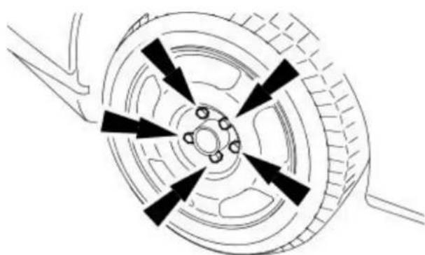
natural_image
Diagram of a car wheel with six directional arrows indicating clockwise motion (no text or labels)Brake System - General Information - Brake System Bleeding
General Procedures

WARNING: Brake Fluid contains polyglycol ethers and polyglycols. Avoid contact with the eyes. Wash hands thoroughly after handling.
If brake fluid contacts the eyes, flush the eyes for 15 minutes with cold running water. Get medical attention if irritation persists. If taken internally, drink water and induce vomiting. Get medical attention immediately. Failure to follow these instructions can result in personal injury.
- CAUTIONS:

Make sure that the vehicle is standing on a level surface or supported on a wheel free lift.

If brake fluid is spilt on the paintwork, the affected areas must be immediately washed down with cold water.
- NOTE: The system consists of separate circuits for each front and diagonally opposite rear wheel. Each front to rear circuit and each wheel circuit can be bled individually of each other.
- NOTE: The service ABS hydraulic control unit is supplied pre-filled with brake fluid. Therefore, a conventional bleed procedure should be adequate to remove all the air from the brake system.

natural_image
Technical line drawing of a mechanical component with no visible text or symbols
natural_image
Technical line drawing of a mechanical assembly with no visible text or symbols
TION: Make sure that the filler cap does not become nated.
Remove the master cylinder reservoir filler cap.
- NOTE: Always use fluid from a sealed container and dispose of used fluid safely.
Fill up the master cylinder reservoir to the MAX mark as necessary.
- Install a bleed tube to the rear right-hand brake caliper bleed nipple.
- Bleed the circuit.
• Make sure the bleed tube is firmly attached to the bleed nipple.
- Submerge the end of the bleed tube in a bleed jar containing a small quantity of approved brake fluid.
- Position the bleed jar base at least 300 mm above the bleed nipple to maintain fluid pressure and prevent air leaking past the bleed nipple threads.
- Open the bleed nipple half a turn.
- Slowly apply the brake pedal to its maximum travel (this forces brake fluid into the bleed jar).
- Close the bleed nipple.
- Return the brake pedal to the rest position.
- Wait 2 seconds to allow the brake fluid to replenish the system.
- Fill up the master cylinder reservoir to the MAX mark as necessary.
- Continue to bleed the circuit until air-free brake fluid is pumped into the jar.
• Fully tighten the bleed nipple.
- Repeat the procedure for the rear left, front right and front left-hand

natural_image
Technical line drawing of a mechanical assembly with no visible text or symbolsbrake circuits.
- Fill up the master cylinder reservoir to the MAX mark.
natural_image
Technical diagram of a vehicle engine compartment with no visible text or symbols- Install the master cylinder reservoir cap.
Lubricants, Fluids, Sealers and Adhesives

CAUTION: Do not use brake fluid ITT Super Dot 4 on 2006my vehicles onwards. Failure to follow this instruction may result in damage or vehicle.
- NOTE: Brake fluid ITT Super Dot 4 has now been superseded by Shell ESL Super Dot 4 which is the Jaguar recommended brake fluid. Shell ESL Super Dot 4 can be used on all model years.
| Item Specification | |
| Brake fluid ITT Super Dot 4 | |
| Brake fluid Shell ESL Super Dot 4 | |
| Brake caliper slide pin grease Klueber GLK1 |
Torque Specifications
| Description Nm lb-ft lb-in | |||
| Brake pipe union 15 11 - | |||
| Brake caliper anchor plate retaining bolts 133 98 - | |||
| Brake caliper retaining bolts 30 22 - | |||
| Brake hose retaining bracket | 40 30 - | ||
| Brake hose to brake caliper | 10 7 | - |
Front Disc Brake - Front Disc Brake
Description and Operation

VUJ0002694
| Item Part Number Description | |
| 1 — Brake hose | |
| 2 — Brake caliper retaining bolts | |
| 3 — Brake pads | |
| 4 — Brake caliper anchor plate | |
| 5 — Brake disc | |
| 6 — Wheel hub | |
| 7 — Wheel knuckle | |
| 8 — Brake hose retaining bracket | |
| 9 — Brake caliper |

WARNING: Brake fluid contains polyglycol ethers and polyglycols. Avoid contact with the eyes. Wash hands thoroughly after handling.
If brake fluid contacts the eyes, flush the eyes for 15 minutes with cold running water. Get medical attention if irritation persists. If taken internally, drink water and induce vomiting. Get medical attention immediately. Failure to follow these instructions can result in personal injury.
- NOTE: Brake system materials inherently generate heat in order to dissipate energy. As a result, occasional squeal is possible, which may be compounded by severe environmental conditions, such as cold, heat, rain, snow, salt and mud.
The front disc brake system consists of the following components:
- Brake pads.
- Single piston, floating brake calipers.
- Brake discs.
- Brake caliper anchor plates.
- Brake hoses.
The brake caliper has two retaining bolts that attach it to the brake caliper anchor plate. The brake caliper anchor plate is attached to the wheel knuckle with two retaining bolts. The hydraulic system provides separate circuits for each pair of diagonally opposed wheels (i.e. left front, right rear and right front, left rear).
The brake disc is manufactured from cast iron and is of the vented type. It is retained on the wheel hub studs by the wheel and wheel nuts.
The brake calipers are mounted on the wheel knuckles. These are of single, sliding piston type which ensures that equal effort is applied through both brake pads.
Front Disc Brake - Front Disc Brake
Diagnosis and Testing
For additional information, refer to Section 206-00 Brake System - General Information.
Front Disc Brake - Brake Caliper
Removal and Installation
| Special Tool(s) | |
| JDS9013 | Brake pedal hold-down tool JDS 9013 |
Removal

- Remove the wheel and tire. For additional information, refer to Section 204-04 Wheels and Tires.
- CAUTION: If brake fluid is spilt on the paintwork, the affected area must be immediately washed down with cold water.
- NOTE: To prevent the loss of brake fluid, apply the brake pedal hold down tool and adjust to hold the brake pedal down 40mm. Install a bleeder bottle to the bleed nipple and loosen.
Detach the brake hose.
- Detach the brake pipe.
- Remove the retaining clip.
-
Detach the brake hose.
-
Detach the brake hose.

natural_image
Technical line drawing of a mechanical assembly with no visible text or symbols- NOTE: Tighten the bleed nipple and remove the bleeder tube and bottle.
Remove the brake caliper.
- Remove and discard the brake caliper retaining bolts.

natural_image
Technical line drawing of a mechanical assembly with no visible text or symbolsInstallation

natural_image
Technical line drawing of a mechanical assembly with arrows indicating motion or force direction (no text or symbols)
natural_image
Technical line drawing of a mechanical assembly with no visible text or symbols
1. CAUTIONS:

If the pistons are pushed back into the housing, brake fluid will be out of the inlet port of the brake caliper.

Make sure that the brake disc faces are clean before installation.
- NOTE: Install new brake caliper retaining bolts.
Install the brake caliper.
- Tighten to 30 Nm.
- Attach the brake hose to the brake caliper.
- Tighten to 10 Nm.
-
Attach the brake hose.
-
Attach the brake hose.
-
Install the retaining clip.
-
Attach the brake pipe.
-
Remove the brake pedal hold down tool.
-
Bleed the brake system. For additional information, refer to Section 206-00 Brake System - General Information.
-
Install the wheel and tire. For additional information, refer to Section 204-04 Wheels and Tires.
Removal

natural_image
Mechanical assembly diagram showing a shaft and housing with directional arrows indicating motion (no text or symbols)- Remove the brake pads, refer to the procedure in this section: Pads.
- Remove and discard the brake caliper anchor plate retaining bolts.
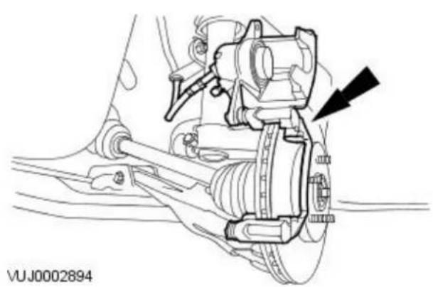
natural_image
Technical line drawing of a mechanical assembly with no visible text or symbols- Detach the brake caliper, brake caliper anchor plate assembly and secure to one side.

natural_image
Technical line drawing of a mechanical assembly with springs and brackets (no text or symbols)- NOTE: If the brake disc is being refitted, the tip of a wheel hub stud must be marked with a corresponding part of the brake disc for correct re-alignment.
Remove the brake disc.
Installation

natural_image
Mechanical assembly diagram showing a vehicle's internal components with arrows indicating motion direction (no text or symbols present)- NOTE: Install new brake caliper anchor plate retaining bolts.
To install, reverse the removal procedure.
- Tighten to 133 Nm.
Removal

- Remove the wheel and tire. For additional information, refer to Section 204-04 Wheels and Tires.
-
Pivot the brake caliper upwards.
-
Remove and discard the brake caliper lower retaining bolt.
-
Pivot the brake caliper upwards.
-
Remove the brake pads.
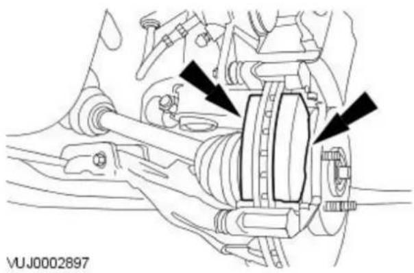
natural_image
Technical line drawing of a mechanical assembly with no visible text or symbolsInstallation
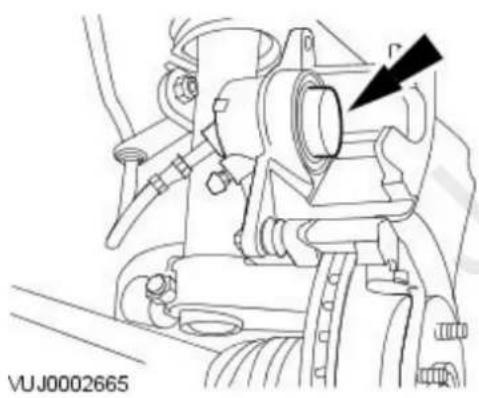
natural_image
Technical line drawing of a mechanical assembly with no visible text or symbols- CAUTIONS:
If the piston is pushed back into the housing, brake fluid will be forced into the fluid reservoir.
Make sure that the brake disc faces are clean before installation. Push the piston into the housing.
- Install the brake pads.

natural_image
Mechanical assembly diagram showing a brake system with no visible text or symbols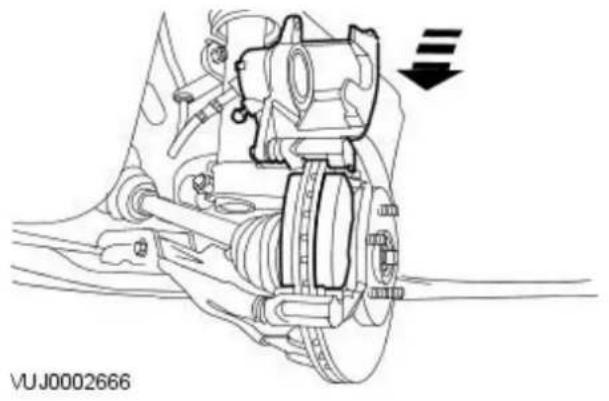
natural_image
Technical line drawing of a vehicle suspension system with no visible text or symbols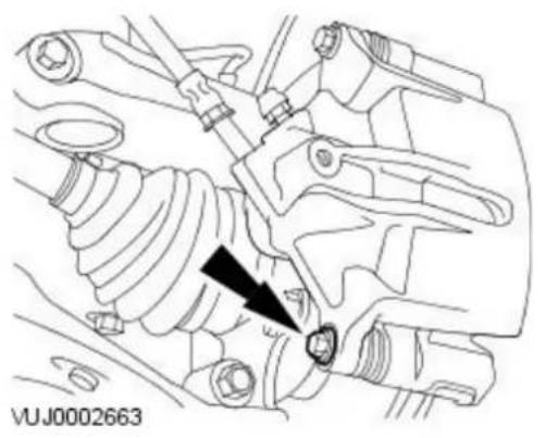
natural_image
Technical line drawing of a mechanical assembly with no visible text or symbols-
Pivot the brake caliper downwards.
-
Install a new brake caliper lower retaining bolt.
- Tighten to 30 Nm.
- Install the wheel. For additional information, refer to Section 204-04 Wheels and Tires.
Lubricants, Fluids, sealers and Adhesives

CAUTION: Do not use brake fluid ITT Super Dot 4 on 2006my vehicles onwards. Failure to follow this instruction may result in damage e vehicle.
- NOTE: Brake fluid ITT Super Dot 4 has now been superseded by Shell ESL Super Dot 4 which is the Jaguar recommended brake fluid. Shell ESL Super Dot 4 can be used on all model years.
| Item Specification | |
| Brake fluid ITT Super Dot 4 | |
| Brake fluid Shell ESL Super Dot 4 | |
| Caliper slide pin grease Dow Corning G807 |
Torque Specifications
| Description Nm lb-ft lb-in | |||
| Brake hose union 38 28 - | |||
| Brake caliper anchor plate retaining bolt 70 52 - | |||
| Brake caliper retaining bolt 32 24 - |
Rear Disc Brake - Rear Disc Brake
Description and Operation

VUJ0003152
| Item Part Number Description | |
| 1 — Parking brake cable | |
| 2 — Hub carrier | |
| 3 — Brake hose | |
| 4 — Brake disc shield | |
| 5 — Brake caliper | |
| 6 — Brake caliper anchor plate | |
| 7 — Brake pads | |
| 8 — Wheel hub | |
| 9 — Brake disc |

WARNING: Brake fluid contains polyglycol ethers and polyglycols. Avoid contact with the eyes. Wash hands thoroughly after handling.
If brake fluid contacts the eyes, flush the eyes for 15 minutes with cold running water. Get medical attention if irritation persists. If taken internally, drink water and induce vomiting. Get medical attention immediately. Failure to follow these instructions may result in personal injury.
- NOTE: Brake system materials inherently generate heat in order to dissipate energy. As a result, occasional squeal is possible, which may be compounded by severe environmental conditions, such as cold, heat, rain, snow, salt and mud.
The rear disc brake system consists of the following components:
- Brake pads.
- Single piston, floating disc calipers.
- Brake discs.
- Brake caliper anchor plates.
- Brake hoses.
- Parking brake cables.
The caliper has two retaining bolts that attach the caliper to the anchor plate. The anchor plate is attached to the hub carrier with two bolts. The hydraulic system provides separate circuits for each pair of diagonally opposed wheels (i.e. left front, right rear and right front, left rear).
The brake disc is manufactured from cast iron and is of the solid type. It is retained on the hub by the wheel and the wheel studs.
The rear brake calipers are mounted on the hub carrier. These are of single, sliding piston type which ensures that equal effort is applied through both brake pads.
The rear brake caliper incorporates the parking brake which is self adjusting according to brake pad wear.
Rear Disc Brake - Rear Disc Brake
Diagnosis and Testing
For additional information, refer to Section 206-00 Brake System - General Information.
Rear Disc Brake - Brake Caliper
Removal and Installation
| Special Tool(s) | |
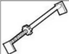 | Brake pedal hold-down toolJDS 9013 |
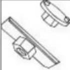 206-08C 206-08C | Brake caliper piston retractor tool206-080 |
 | Crankshaft pulley/damper remover303-588 |
Removal
- Remove the wheel and tire. For additional information, refer to: Wheel and Tire (204-04 Wheels and Tires, Removal and Installation).
-
Detach the parking brake cable.
-
Release the tension.
- Detach the parking brake cable.


natural_image
Technical diagram of a mechanical assembly with bolts and a valve (no text or symbols)- Remove the parking brake cable retaining clip.

natural_image
Technical line drawing of a vehicle's seatbelt mechanism (no text or symbols)
natural_image
Technical line drawing of a mechanical component with arrows indicating assembly or movement (no text or symbols)-
CAUTION: If brake fluid is spilt on the paintwork, the affected area must be immediately washed down with cold water.
-
NOTE: To prevent the loss of brake fluid, apply the brake pedal hold down tool and adjust to hold the brake pedal down 40mm. Install a bleeder bottle to the bleed nipple and loosen.
- NOTE: Remove and discard the brake hose sealing washers.
Detach the brake hose.
- NOTE: Tighten the bleed nipple and remove the bleeder tube and bottle.
Remove the brake caliper.
- Remove and discard the brake caliper retaining bolts.
Installation

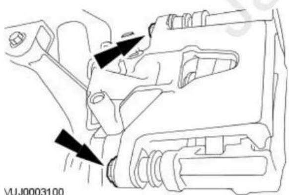
natural_image
Technical line drawing of a mechanical assembly with arrows indicating components (no text or symbols)- CAUTION: If the piston is pushed back into the housing, brake fluid will be forced out of the inlet port of the brake caliper.
- NOTE: The left-hand brake caliper piston retracts counter clockwise and the right-hand retracts clockwise.
Using the special tools, fully retract the brake caliper piston.
2. CAUTIONS:
Make sure the piston location mark is in the correct position so that the locator pin on the brake pad backing plate locates correctly into the piston.
Make sure that the brake disc faces are clean before installation.
- NOTE: Install new brake caliper retaining bolts.
Install the brake caliper.
- Tighten to 32 Nm.

natural_image
Technical line drawing of a vehicle's seatbelt mechanism (no text or symbols)
natural_image
Technical diagram of a mechanical assembly with bolts and a bolt, no visible text or symbols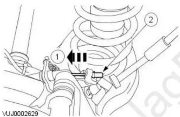
- NOTE: Install new brake hose sealing washers.
Attach the brake hose.
- Tighten to 38 Nm.
- Remove the brake pedal hold down tool.
- Bleed the brake system. For additional information, refer to: Brake System Bleeding (206-00 Brake System - General Information, General Procedures).
-
Attach the parking brake cable retaining clip.
-
Attach the parking brake cable.
-
Release the tension.
-
Attach the parking brake cable.
-
Install the wheel and tire. For additional information, refer to: Wheel and Tire (204-04 Wheels and Tires, Removal and Installation).
Removal
All vehicles
- Remove the brake pads. For additional information, refer to: Brake Pads (206-04 Rear Disc Brake, Removal and Installation).
Vehicles with 2.5L or 3.0L engine
- Detach the Anti-lock brake system (ABS) wheel speed sensor.
- Remove the ABS wheel speed sensor retaining bolt.
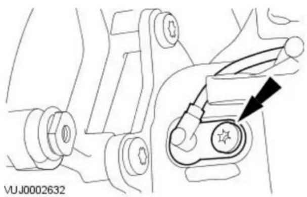
natural_image
Mechanical assembly diagram showing a belt switch mechanism with no visible text or symbolsAll vehicles
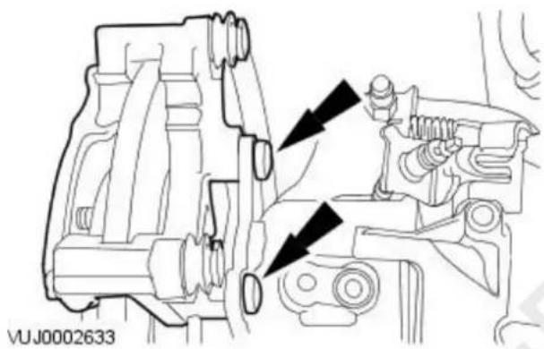
natural_image
Technical line drawing of a mechanical assembly with arrows indicating motion or force direction (no text or symbols)- Remove the brake caliper anchor plate.
- Remove and discard the brake caliper anchor plate retaining bolts.

natural_image
Technical line drawing of a car brake system with a circular component and mounting bracket (no text or symbols)- NOTE: If the brake disc is being refitted, the tip of a wheel hub stud must be marked with a corresponding part of the brake disc for correct re-alignment.
Remove the brake disc.
Installation

natural_image
Technical line drawing of a mechanical assembly with arrows indicating components (no text or symbols)- NOTE: Install new brake caliper anchor plate retaining bolts.
To install, reverse the removal procedure.
- Tighten to 70 Nm.
- Remove the rear wheel hub. For additional information, refer to Section 204-02 Rear Suspension.
Rear Disc Brake - Brake Pads
Removal and Installation
| Special Tool(s) | |
| 206-08C | Brake caliper piston retractor tool 206-080 |
| 303-58I | Crankshaft pulley/damper remover 303-588 |
Removal

-
Remove the wheel and tire. For additional information, refer to: Wheel and Tire (204-04 Wheels and Tires, Removal and Installation).
-
Detach the parking brake cable.
-
Release the tension.
-
Detach the parking brake cable.
-
Remove the parking brake cable retaining clip.

natural_image
Technical diagram of a mechanical assembly with bolts and a valve (no text or symbols)
natural_image
Technical line drawing of a mechanical assembly with arrows indicating components (no text or symbols)- Detach the brake caliper and secure to one side.
- Remove and discard the brake caliper retaining bolts.

natural_image
Mechanical assembly diagram showing a brake caliper and suspension components (no text or labels)- Remove the brake pads.
Installation

- CAUTION: If the piston is pushed back into the housing, brake fluid will be forced back into the fluid reservoir.
- NOTE: The left-hand brake caliper piston retracts counter clockwise and the right-hand retracts clockwise.
Using the special tools, fully retract the brake caliper piston.

natural_image
Technical diagram of a vehicle brake system with mounting brackets and suspension components (no text or labels)- Install the brake pads.
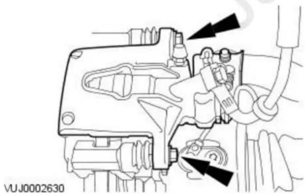
natural_image
Technical line drawing of a mechanical assembly with no visible text or symbols- CAUTIONS:
Make sure that the brake disc faces are clean before installation.
Make sure the piston location mark is in the correct position so that the locator pin on the brake pad backing plate locates correctly into the piston.
- NOTE: Install new brake caliper retaining bolts.
Attach the brake caliper.
- Tighten to 32 Nm.

natural_image
Technical line drawing of a mechanical assembly with bolts and nuts (no text or symbols)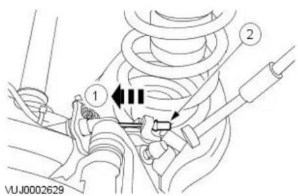
-
Attach the parking brake cable retaining clip.
-
Attach the parking brake cable.
-
Release the tension.
-
Attach the parking brake cable.
-
Install the wheel and tire.
For additional information, refer to: Wheel and Tire (204-04 Wheels and Tires, Removal and Installation).
Parking Brake and Actuation -
Torque Specifications
| Description Nm lb-ft lb-in | |||
| Parking brake control retaining nuts 20 15 - |
Item Part Number Description
1 — Front cable
2 — Rear cable
3 — Brake calipers
The parking brake control system is cable-operated and controlled by an independent hand-operated parking brake control lever. The parking brake control lever activates the rear brake calipers through a cable and rear caliper lever with a ball in ramp mechanism. The rear caliper self adjusts to compensate for pad wear through hydraulic operation.
To adjust the cable, operate the parking brake control lever several times.
Parking Brake and Actuation - Parking Brake
Diagnosis and Testing
Inspection and Verification
- Verify the customer concern by operating the system to duplicate the condition.1.
- Visually inspect for obvious signs of mechanical or electrical damage.2.
Visual Inspection Chart
| Mechanical Electrical | |
| Mechanical Electrical | |
| Parking brake control Parking | brake control warning circuit. For additional information, refer toREFER to:Instrument Cluster(413-01 Instrument Cluster, Diagnosis and Testing). |
| Cable and conduit | |
| Equalizer | |
-
- If an obvious cause for an observed or reported concern is found, correct the cause (if possible) before proceeding to the next step.
- If the concern is not visually evident, verify the symptom and refer to the Symptom Chart.4.
Symptom Chart
| Symptom Possible Sources Action | ||
| The parking brake will not engage Parking brake control. | * * Cable and conduit. | * Go to Pinpoint Test A. |
| The parking brake will not release Cable and conduit. | * * Parking brake control. | * Go to Pinpoint Test B. |
Pinpoint tests
PINPOINT TEST A : THE PARKING BRAKE WILL NOT ENGAGE TEST CONDITIONS DETAILS/ RESULTS/ ACTIONS
| A1: CHECK FOR INCORRECTLY ADJUSTED REAR PARKING BRAKE CABLE | |
| 1 Operate the parking brake control several times to adjust the cable. | |
| Does the parking brake now engage correctly?Yes Vehicle OK.No GO to A2. | |
| A2: CHECK FOR WORN BRAKE PADS | |
| 1 Inspect the brake pads for excessive wear. For additional information, refer toREFER to: Brake System (206-00 Brake System - General Information, Diagnosis and Testing). | |
| Are brake pads OK?Yes GO to A3.No INSTALL new brake pads. Test the system for normal operation. | |
| A3: CHECK FOR DAMAGED PARKING BRAKE CABLES | |
| 1 Inspect the parking brake cables and conduit for damage, rust or fraying. | |
| Are the parking brake cables and conduits OK?Yes CHECK for other causes such as loose parking brake control or conventional brake system components.No REPAIR or INSTALL new cables and conduit as necessary. TEST the system for normal operation. | |
| TEST CONDITIONS | DETAILS/ RESULTS/ ACTIONS |
| B1: CHECK PARKING BRAKE CONTROL | |
| 1 Raise and support the vehicle with the parking brake fully applied. For additional information, refer toREFER to:Lifting(100-02 Jacking and Lifting, Description and Operation).Release the parking brake by pulling upwards on the control lever and pushing the release button. | |
| Did the parking button release?YesCHECK for other causes such as conventional brake system components, REPAIR or INSTALL new components as necessary.NoGO to B2. | |
| B2: CHECK PARKING BRAKE CABLES | |
| 1 Loosen the parking brake cable tension.Rotate the wheels by hand. | |
| Did the rear wheels rotate OK?YesINSTALL a new parking brake control; Refer to the procedures in this section. TEST the system for normal operation.NoGO to B3. | |
| B3: CHECK FRONT PARKING BRAKE CABLE | |
| 1 Disconnect the parking brake front cable from the rear brake cable and conduit at the equalizer.● Rotate the wheels by hand. | |
| Did the rear wheels rotate OK?YesINSTALL a new front parking brake cable. For additional information, refer to the procedure in this section:REFER to:Parking Brake Cable - Vehicles With: Manually Adjusted Parking Brake (206-05 Parking Brake and Actuation, Removal and Installation).TEST the system for normal operation.NoGO to B4. | |
| B4: CHECK REAR PARKING BRAKE CABLES | |
| 1 Disconnect the parking brake rear cable from the rear brake calipers, one at a time.● Rotate the wheel affected by the disconnected parking brake. | |
| Did the rear wheel rotate OK?YesINSTALL a new rear parking brake cable. For additional information, refer to the procedure in this section:REFER to:Parking Brake Cable - Vehicles With: Manually Adjusted Parking Brake (206-05 Parking Brake and Actuation, Removal and Installation).TEST the system for normal operation.NoFor additional information, refer toREFER to:Brake System (206-00 Brake System - General Information, Description and Operation). | |
Yes
No
B4: CHECK REAR PARKING BRAKE CABLES
Yes
No
Parking Brake and Actuation - Parking Brake Cable Vehicles With: Manually Adjusted Parking Brake
Removal and Installation
| Special Tool(s) | |
| 206-087 | Parking brake cable adjuster socket.206-087 |


natural_image
Technical diagram of a mechanical assembly with bolts and fasteners (no text or symbols)
natural_image
Mechanical assembly diagram showing a spring and tool interacting with a mechanical component (no text or symbols)Removal
- Release the parking brake.
-
Raise and support the vehicle. For additional information, refer to Section 100-02 Jacking and Lifting.
-
NOTE: 2.5L or 3.0L shown, 2.0L similar.
- NOTE: Using special tool 206-087 loosen the rear parking brake cable. Loosen the rear parking brake cables retaining nut.
-
NOTE: 2.5L or 3.0L shown, 2.0L similar. Detach the rear parking brake cables.
-
Detach the rear parking brake cable.

natural_image
Technical line drawing of a mechanical assembly with no visible text or symbols- Remove the rear parking brake cable retaining clip.

natural_image
Mechanical assembly diagram showing a pipe connection with three arrows indicating flow direction (no text or symbols present)- Detach the rear parking brake cable and conduit.
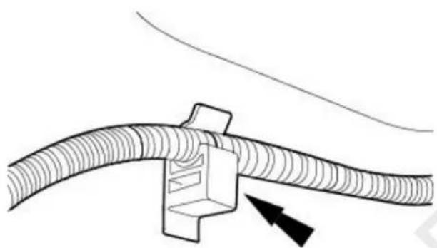
natural_image
Diagram of a cable connector with a directional arrow indicating movement (no text or symbols)- Detach the rear parking brake cable and conduit.

- Detach the rear parking brake cable and conduit.

natural_image
Technical diagram showing a mechanical component with circular holes and a pointer, no readable text or symbols present.- Remove the rear parking brake cable and conduit.
Installation
- To install, reverse the removal procedure.
- Carry out the parking brake cable adjustment. For additional information, refer to Parking Brake Cable Adjustment - in this section.
Parking Brake and Actuation - Parking Brake Cable Vehicles With: Self-Adjusting Parking Brake
Removal and Installation
Removal

- Remove the rear road wheel and tire. For additional information, refer to Section 204-04 Wheels and Tires.
-
Detach the rear parking brake cable.
-
Release the tension.
-
Detach the rear parking brake cable.
-
Detach the parking brake cable and conduit.
-
Release the parking brake conduit retaining tangs.
- Detach the parking brake cable and conduit.
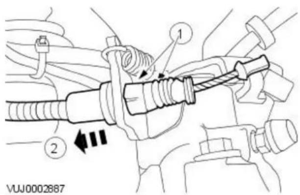
- Detach the parking brake cable and conduit.

natural_image
Mechanical assembly diagram showing a bracket with mounting holes and a black arrow indicating a specific component (no text or symbols present)
natural_image
Diagram of a cable connector with a directional arrow indicating movement (no text or symbols)- Remove the body undertray. For additional information, refer to Section 501-08 Exterior Trim and Ornamentation.
- Detach the parking brake cable and conduit.
VUJ0002826

natural_image
Technical diagram of a mechanical assembly with no visible text or symbols- Detach the parking brake cable and conduit.
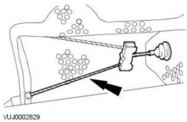
- Detach the rear parking brake cable.

- Remove the parking brake rear cable and conduit.
Installation
- To install, reverse the removal procedure.
Parking Brake and Actuation - Parking Brake Control Vehicles With: Manually Adjusted Parking Brake
Removal and Installation
| Special Tool(s) | |
| 206-087 | Parking brake cable adjuster socket.206-087 |
Removal All vehicles

natural_image
Line drawing of a hand holding a clip, with no visible text or symbols- Remove the center console. For additional information, refer to Section 501-12 Instrument Panel and Console.
- Disconnect the parking brake warning indicator switch electrical connector.
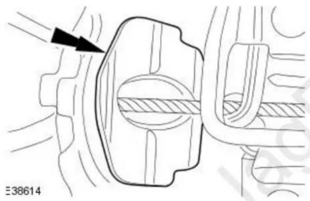
natural_image
Technical diagram of a mechanical component with no visible text or symbols- Detach the park brake grommet.

- Release the parking brake.
- Raise and support the vehicle. For additional information, refer to Section 100-02 Jacking and Lifting.
- NOTE: 2.5L or 3.0L shown, 2.0L similar.
- NOTE: Using special tool 206-087 loosen the rear parking brake cables. Loosen the rear parking brake cables retaining nut.
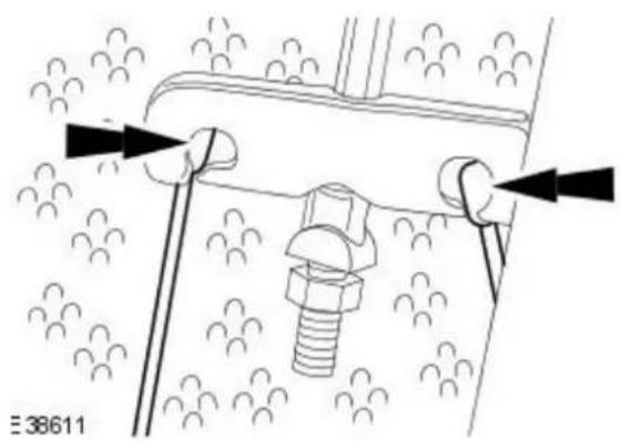
natural_image
Technical diagram of a mechanical assembly with bolts and arrows indicating motion (no text or symbols)- NOTE: 2.5L or 3.0L shown, 2.0L similar.
Detach the rear parking brake cables.
Vehicles with 2.5L or 3.0L engine
- Remove the driveshaft. For additional information refer to Section 205-01 Driveshaft.
All vehicles

- Remove the parking brake.
Installation
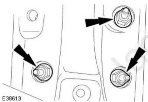
- To install, reverse the removal procedure.
- Tighten to 25 Nm.
- Carry out the parking brake cable adjustment. For additional information, refer to Parking Brake Cable Adjustment - in this section.
Parking Brake and Actuation - Parking Brake Control Vehicles With: Self-Adjusting Parking Brake
Removal and Installation
Removal
All vehicles
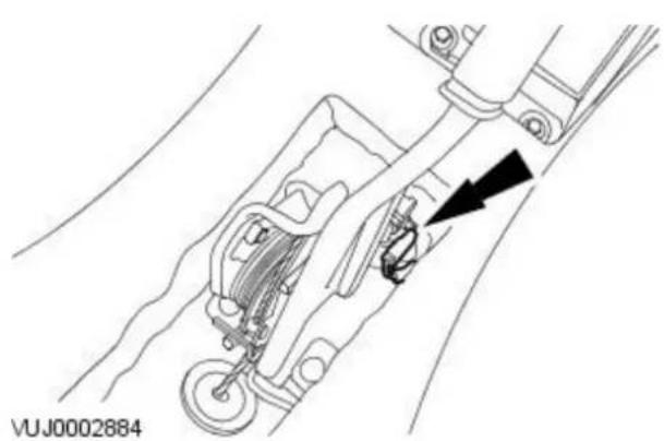
natural_image
Technical line drawing of a mechanical assembly with a black arrow indicating a specific component (no text or symbols present)- Remove the center console. For additional information, refer to Section 501-12 Instrument Panel and Console.
-
Disconnect the parking brake warning indicator switch electrical connector.
-
Release the parking brake.
-
Remove the rear road wheels and tires. For additional information, refer to Section 204-04 Wheels and Tires.
Vehicles with 2.5L or 3.0L engine
- Remove the driveshaft. For additional information refer to Section 205-01 Driveshaft.
All vehicles
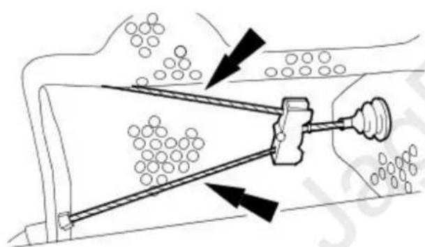
natural_image
Diagram of a mechanical device emitting particles through a channel, with directional arrows indicating flow or force (no text or symbols present)- Remove the exhaust front muffler. For additional information, refer to Section 309-00 Exhaust System.
- Detach the parking brake rear cables.
VUJ0003184
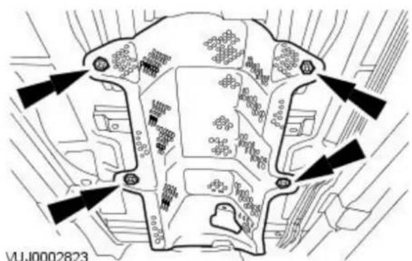
- Remove the exhaust front heat shield.

- Remove the exhaust rear heat shield.

- Remove the parking brake control retaining nuts.

- Lower the vehicle.
-
Detach the parking brake control.
-
Detach the parking brake cable grommet.
- Detach the parking brake control.

-
Remove the parking brake control.
-
Align the flat on the nipple to clear the spring.
- Remove the parking brake control.

- To install, reverse the removal procedure.
- Tighten to 20 Nm.
Hydraulic Brake Actuation -
Lubricants, Fluids, Sealers and Adhesives

CAUTION: Do not use brake fluid ITT Super Dot 4 on 2006my vehicles onwards. Failure to follow this instruction may result in damage or vehicle.
- NOTE: Brake fluid ITT Super Dot 4 has now been superseded by Shell ESL Super Dot 4 which is the Jaguar recommended brake fluid. Shell ESL Super Dot 4 can be used on all model years.
| Item Specification | |
| Brake fluid ITT Super Dot 4 | |
| Brake fluid Shell ESL Super Dot 4 |
Torque Specifications
| Description Nm Ib-ft Ib-in | |||
| Brake master cylinder retaining nuts. 20 15 - | |||
| Brake tube to brake master cylinder unions. 15 11 - |
Hydraulic Brake Actuation - Hydraulic Brake Actuation
Description and Operation
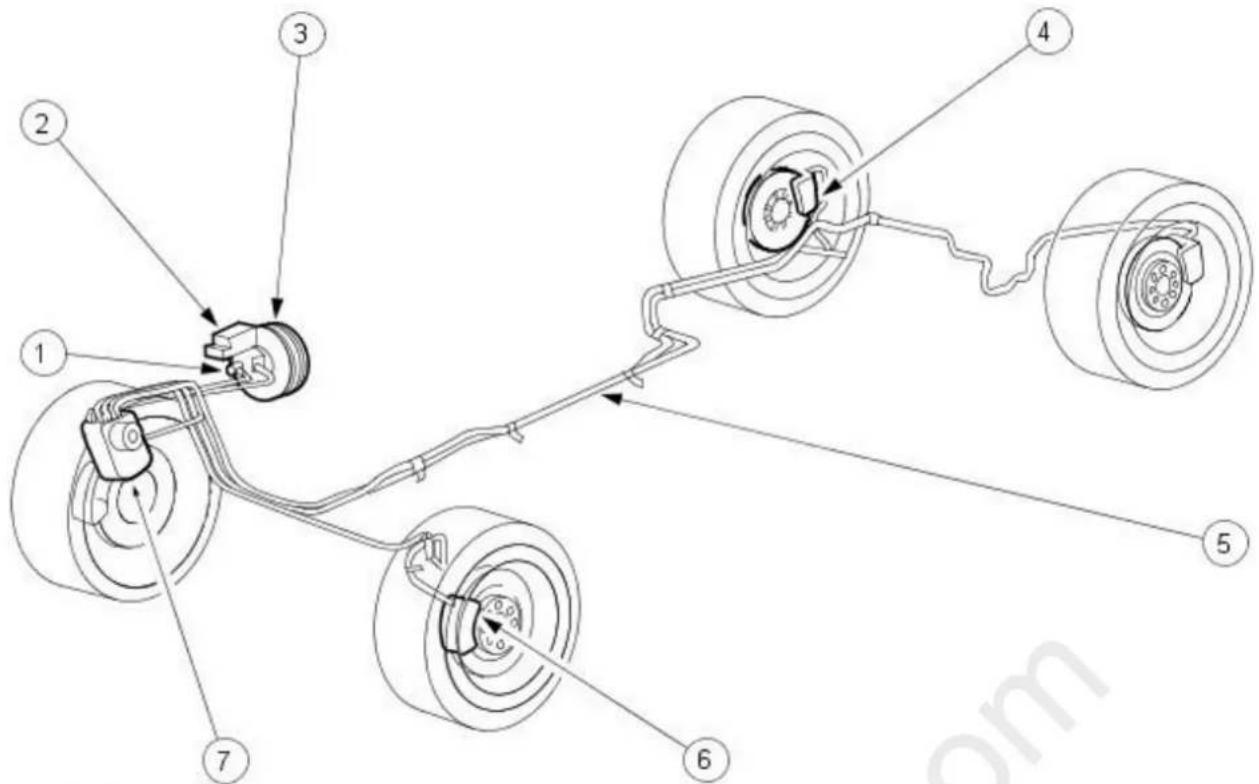
VUJ0003005
| Item Part Number Description | |
| 1 — Brake master cylinder | |
| 2 — Brake fluid reservoir | |
| 3 — Brake booster | |
| 4 — Rear brake caliper | |
| 5 — Brake tubes | |
| 6 — Front brake caliper | |
| 7 — Hydraulic control unit |

WARNING: Brake fluid contains polyglycol ethers and polyglycols. Avoid contact with the eyes. Wash hands thoroughly after handling.
If brake fluid contacts the eyes, flush the eyes for 15 minutes with cold running water. Get medical attention if irritation persists. If taken internally, drink water and induce vomiting. Get medical attention immediately. Failure to follow these instructions may result in personal injury.
The hydraulic brake system is of a pedal operated, diagonally split dual line brake system that consists of the following components:
- a brake booster
• a master cylinder and reservoir
• front brake calipers
• rear brake calipers - brake tubes and hoses
• Anti-lock brake system (ABS) - Traction control system (TCS)/Interactive vehicle dynamics (IVD)
Brake Master Cylinder
The brake master cylinder is a dual piston type. The master cylinder operates as follows:
- when the brake pedal is applied, pressure is applied by mechanical linkage to the primary and secondary systems
- brake master cylinder pistons apply hydraulic pressure to the two circuits
The master cylinder consists of the following components:
• primary and secondary pistons
- brake fluid reservoir with integral fluid level warning indicator
Hydraulic Brake Actuation - Hydraulic Brake Actuation
Diagnosis and Testing
For additional information, refer to Section 206-00 Brake System - General Information.
Hydraulic Brake Actuation - Brake Fluid Reservoir
Removal and Installation
Removal
All vehicles
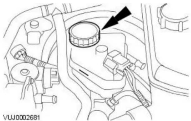
natural_image
Technical line drawing of a vehicle engine compartment with no visible text or symbols- CAUTION: If brake fluid is spilt on the paintwork, the affected area must be immediately washed down with cold water.
- NOTE: Make sure the filler cap does not become contaminated. Remove the brake fluid reservoir filler cap.
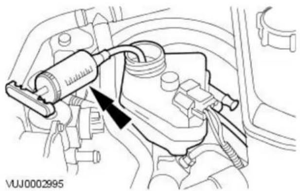
natural_image
Technical diagram of a mechanical assembly with no visible text or symbols- Using a suitable suction device drain the brake fluid reservoir.

natural_image
Technical line drawing of a car engine component with no visible text or symbols- Disconnect the brake fluid low level warning indicator electrical connector.
Vehicles with manual transmission
- Detach the clutch master cylinder feed hose.

natural_image
Technical line drawing of a car engine component with no visible text or symbolsAll vehicles

- NOTE: Remove and discard the O-ring seals from the brake master cylinder.
Remove the brake fluid reservoir.
- Release one leg of the reservoir from the retaining pin.
- Remove the brake fluid reservoir.
Installation
All vehicles
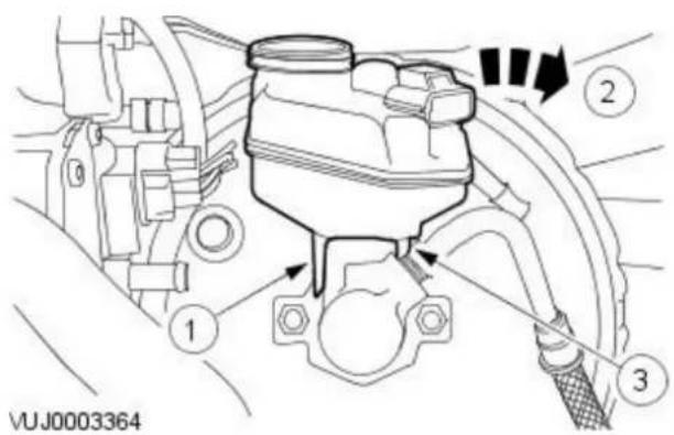
- NOTE: Install new O-ring seals to the brake master cylinder.
Install the brake fluid reservoir.
- Locate the left hand brake fluid reservoir leg to the retaining pin.
- Fully seat the brake fluid reservoir to the master cylinder.
- Fully seat the right hand brake fluid reservoir leg to the retaining pin.
Vehicles with manual transmission
- Attach the clutch master cylinder feed hose.

natural_image
Technical line drawing of a mechanical component with no visible text or symbolsAll vehicles

natural_image
Technical line drawing of a mechanical assembly with no visible text or symbols- Connect the brake fluid low level warning indicator electrical connector.

natural_image
Technical line drawing of a mechanical assembly with no visible text or symbols- Fill the brake fluid reservoir.

natural_image
Technical line drawing of a car engine component with no visible text or symbols- Bleed the brake system. For additional information, refer to Section 206-00 Brake System - General Information.
- Install the brake fluid reservoir filler cap.
Hydraulic Brake Actuation - Brake Master Cylinder
Removal and Installation
Removal
All vehicles
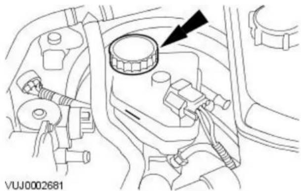
natural_image
Technical line drawing of a mechanical component with no visible text or symbols- CAUTION: If brake fluid is spilt on the paintwork, the affected area must be immediately washed down with cold water.
- NOTE: Make sure the filler cap does not become contaminated. Remove the brake fluid reservoir filler cap.

natural_image
Technical diagram of an engine component with a valve and hose assembly (no text or labels)- Using a suitable suction device drain the brake fluid reservoir.

natural_image
Technical line drawing of a mechanical assembly with no visible text or symbols- Disconnect the brake fluid low level warning indicator electrical connector.

natural_image
Technical line drawing of an engine component with a black arrow indicating a specific part (no text or symbols present)- Detach the brake booster vacuum hose.

natural_image
Technical line drawing of a car engine component with no visible text or symbols- Detach the clutch master cylinder feed hose.
All vehicles

-
Reposition the coolant expansion tank.
-
Remove the coolant expansion tank retaining bolt.
- Turn the coolant expansion tank counter clockwise.
- Reposition the coolant expansion tank.
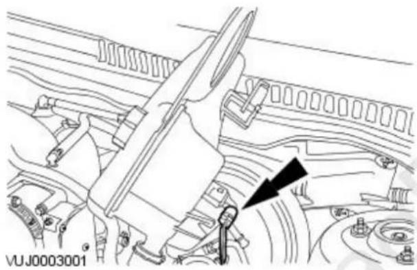
natural_image
Technical line drawing of a car engine compartment with no visible text or symbols- Disconnect the coolant low level warning indicator electrical connector.

natural_image
Technical diagram of a vehicle engine assembly with hoses and valves (no text or labels)- Disconnect the brake fluid supply tubes.
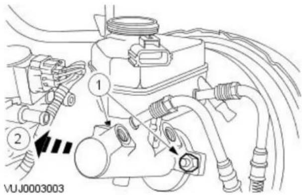
- NOTE: Remove and discard the O-ring seal at the rear of the brake master cylinder.
Remove the brake master cylinder and reservoir.
- Remove the brake master cylinder retaining nuts.
- Remove the brake master cylinder and reservoir.
Installation
All vehicles

- NOTE: Install a new O-ring seal to the rear of the brake master cylinder.
Install the brake master cylinder and reservoir.
- Install the brake master cylinder and reservoir.
- Install the brake master cylinder retaining nuts.
-
Tighten to 20 Nm.
-
Connect the brake fluid supply tubes.
- Tighten to 15 Nm.

natural_image
Technical diagram of a vehicle engine assembly with hoses and components (no text or labels)- Connect the coolant low level warning indicator electrical connector.
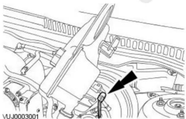
natural_image
Technical line drawing of a mechanical assembly with no visible text or symbols
-
Attach the coolant expansion tank.
-
Reposition the coolant expansion tank.
- Turn the coolant expansion tank clockwise.
- Install the coolant expansion tank retaining bolt.
Vehicles with manual transmission
- Attach the clutch master cylinder feed hose.

natural_image
Technical line drawing of a car engine component with no visible text or symbolsAll vehicles

natural_image
Technical line drawing of an engine component with a black arrow indicating a specific part (no text or symbols present)- Attach the brake booster vacuum hose.
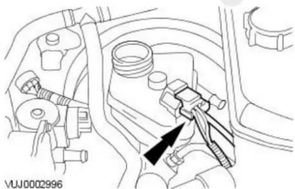
natural_image
Technical line drawing of a mechanical assembly with no visible text or symbols- Connect the brake fluid low level warning indicator electrical connector.

natural_image
Technical line drawing of a mechanical assembly with no visible text or symbols- Fill the brake fluid reservoir.

natural_image
Technical line drawing of a car engine compartment with no visible text or symbols-
Bleed the brake system. For additional information, refer to Section 206-00 Brake System - General Information.
-
Install the brake fluid reservoir filler cap.
Hydraulic Brake Actuation - Brake Pedal and Bracket
Removal and Installation
Removal
Vehicles with manual transmission
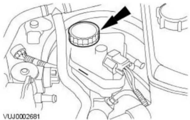
natural_image
Technical line drawing of a vehicle engine compartment with a black arrow pointing to a circular component (no text or symbols present)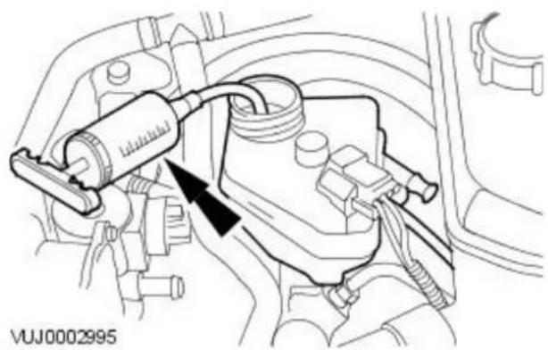
natural_image
Technical line drawing of an engine component with hoses and a valve, no visible text or symbols
- WARNING: Brake fluid contains polyglycol ethers and polyglycols. Avoid contact with the eyes. Wash hands thoroughly after handling. If brake fluid contacts the eyes, flush the eyes for 15 minutes with cold water. Get medical attention immediately if irritation persists. If taken internally, drink water and induce vomiting. Get medical attention immediately. Failure to follow these instructions may result in personal injury.
CAUTION: If brake fluid is spilt on the paintwork, the affected area must be immediately washed down with cold water.
- NOTE: Make sure the filler cap does not become contaminated. Remove the brake fluid reservoir filler cap.
-
CAUTION: If brake fluid is spilt on the paintwork, the affected area must be immediately washed down with cold water. Using a suitable suction device, drain the brake fluid reservoir.
-
NOTE: Vehicles with 2.5L or 3.0L engine only. Detach the engine wiring harness.

natural_image
Technical line drawing of a car interior showing hoses and a valve (no text or symbols)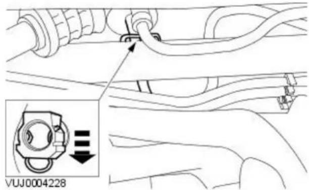
-
CAUTION: If brake fluid is spilt on the paintwork, the affected area must be immediately washed down with cold water.
-
NOTE: Install suitable blanking plugs.
- NOTE: Right-hand drive shown, left-hand drive similar.
Disconnect the clutch master cylinder supply line.
- CALATION: If brake fluid is spilt on the paintwork, the affected area must be immediately washed down with cold water.
• NOTE: Install suitable blanking plugs.
- NOTE: Right-hand drive shown, left-hand drive similar.
Disconnect the clutch slave cylinder supply line from the clutch master cylinder.
- Release the retaining clip to disconnect the line.
Right-hand drive vehicles
- Remove the brake pedal and bracket retaining nuts.

natural_image
Technical diagram of a mechanical assembly with directional arrows indicating motion or force (no text or symbols)Vehicles without driver lower air bag
- Remove the driver side instrument panel lower trim panel.
natural_image
Diagram showing a curved path with a directional arrow and a square marker, no text or symbols presentVUJ0004808
Vehicles with driver lower air bag
- Remove the driver lower air bag. For additional information, refer to: Driver Lower Air Bag Module (501-20B Supplemental Restraint System, Removal and Installation).
All vehicles

- Remove the support panel.
Left-hand drive vehicles
- Position the front wheels in a straight ahead position and centralize the steering wheel.
- Lock in position and remove the ignition key.
- Detach the steering column.
- Remove and discard the steering column lower retaining bolt.

All vehicles
-
Remove the accelerator pedal. For additional information, refer to: Accelerator Pedal (310-02 Acceleration Control, Removal and Installation).
-
Detach the wiring harness.

natural_image
Technical line drawing of a mechanical assembly with no visible text or symbols
-
Remove the anti-collapse bracket clevis pin.
-
Remove the anti-collapse bracket clevis pin retaining clip.
- Remove the anti-collapse bracket clevis pin.
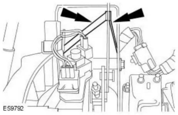
natural_image
Technical line drawing of a mechanical assembly with arrows indicating direction (no text or symbols)- Reposition the anti-collapse bracket.
Right-hand drive vehicles

natural_image
Technical line drawing of a mechanical assembly with no visible text or symbols- Remove the brake booster push rod retaining nut.
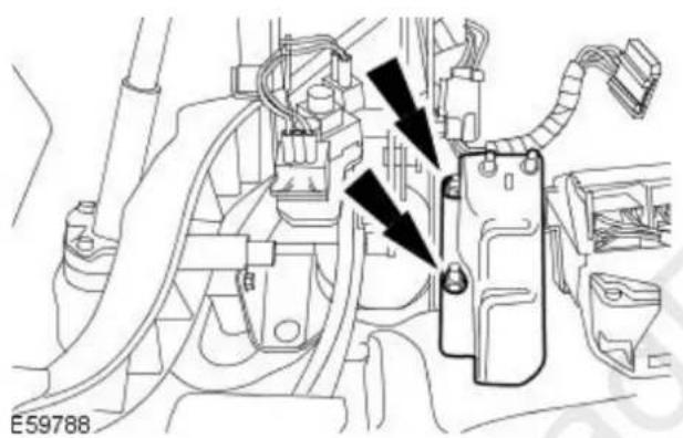
natural_image
Technical diagram of an automotive electrical panel with no visible text or symbols- Remove the accelerator pedal mount bracket.
Left-hand drive vehicles

-
Remove the brake booster push rod retaining clip.
-
Release the brake booster push rod retaining clip.
- Remove the brake booster push rod retaining clip.

natural_image
Technical line drawing of a mechanical component with directional arrows indicating assembly or movement (no text or symbols)- Remove the accelerator pedal mount bracket.

natural_image
Technical diagram of a mechanical component with two black arrows pointing to specific parts (no text or symbols present)- Remove the brake pedal and bracket retaining nuts.
All vehicles

natural_image
Technical diagram of a mechanical assembly with two bolted components and directional arrows indicating motion (no text or symbols)- Remove the brake pedal and bracket retaining nuts.

natural_image
Technical line drawing of a mechanical assembly with no visible text or symbols- NOTE: Right-hand drive shown, left-hand drive similar.
Remove the brake pedal and bracket.
- Disconnect the electrical connector.
Installation
All vehicles

natural_image
Technical diagram of a mechanical assembly with no visible text or symbols- NOTE: Right-hand drive shown, left-hand drive similar. Install the brake pedal and bracket.
- Connect the electrical connector.
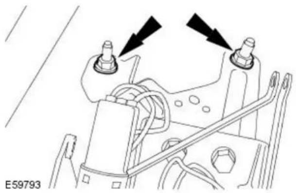
natural_image
Technical diagram of a mechanical assembly with two bolted components and directional arrows indicating motion (no text or symbols)- Install the brake pedal and bracket retaining nuts.
- Tighten to 25 Nm.
Left-hand drive vehicles

natural_image
Technical diagram of a mechanical component with two black arrows pointing to specific parts (no text or symbols present)- Install the brake pedal and bracket retaining nuts.
- Tighten to 25 Nm.

- Install the accelerator pedal mount bracket.
- Tighten to 25 Nm.

natural_image
Mechanical assembly diagram showing a valve mechanism with a directional arrow (no text or symbols)- Install the brake booster push rod retaining clip.
Right-hand drive vehicles

natural_image
Technical diagram of an automotive electrical panel with no visible text or symbols- Install the accelerator pedal mount bracket.
- Tighten to 25 Nm.

natural_image
Technical line drawing of a mechanical assembly with no visible text or symbols- Install the brake booster push rod retaining nut.
- Tighten to 3 Nm.
All vehicles
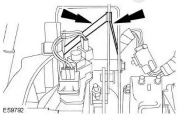
natural_image
Technical line drawing of a mechanical assembly with no visible text or symbols- Reposition the anti-collapse bracket.

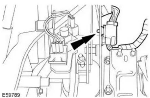
natural_image
Technical line drawing of a mechanical assembly with no visible text or symbols-
Install the anti-collapse bracket clevis pin retaining clip.
-
Install the anti-collapse bracket clevis pin.
-
Install the anti-collapse bracket clevis pin retaining clip.
-
Attach the wiring harness.
-
Install the accelerator pedal.
For additional information, refer to: Accelerator Pedal (310-02 Acceleration Control, Removal and Installation).
Left-hand drive vehicles

- Attach the steering column.
• Install a new steering column lower retaining bolt.
- Tighten to 25 Nm.
All vehicles
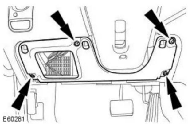
- Install the support panel.
Vehicles with driver lower air bag
- Install the driver lower air bag.
For additional information, refer to: Driver Lower Air Bag Module (501-20B Supplemental Restraint System, Removal and Installation).
Vehicles without driver lower air bag
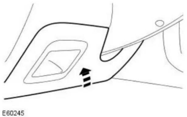
natural_image
Diagram showing a curved path with nested contours and directional arrows, no readable text or symbols present.- Install the driver side instrument panel lower trim panel.
Right-hand drive vehicles
- Install the brake pedal and bracket retaining nuts.
- Tighten to 25 Nm.

natural_image
Technical diagram of a mechanical assembly with directional arrows indicating motion or force (no text or symbols)Vehicles with manual transmission
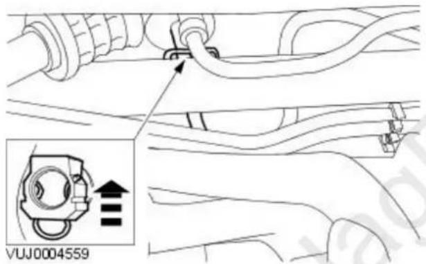
-
CAUTION: If brake fluid is spilt on the paintwork, the affected area must be immediately washed down with cold water.
-
NOTE: Remove the blanking plugs.
• NOTE: Reposition the retaining clip. - NOTE: Right-hand drive shown, left-hand drive similar.
Connect the clutch slave cylinder supply line to the clutch master cylinder.

natural_image
Diagram of a car interior showing hoses and a valve mechanism (no text or symbols)-
CAUTION: If brake fluid is spilt on the paintwork, the affected area must be immediately washed down with cold water.
-
NOTE: Remove the blanking plugs.
- NOTE: Right-hand drive shown, left-hand drive similar.
Connect the clutch master cylinder supply line.
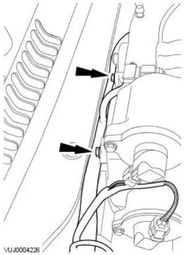
natural_image
Technical diagram of a vehicle suspension system with hoses and wiring (no text or symbols)- NOTE: Vehicles with 2.5L or 3.0L engine only.
Attach the engine wiring harness.
- Tighten to 10 Nm.

natural_image
Technical diagram of a vehicle engine component with no visible text or symbols- Bleed the hydraulic clutch system.
For additional information, refer to: Clutch System Bleeding - Vehicles
With: 6-Speed Manual Transaxle - MMT6 (308-00 Manual
Transmission/Transaxle and Clutch - General Information, General
Procedures).
- CAUTION: If brake fluid is spilt on the paintwork, the affected area must be immediately washed down with cold water.
- NOTE: Make sure the filler cap does not become contaminated.
Install the brake fluid reservoir filler cap.
Hydraulic Brake Actuation - Brake Pedal Cross-Shaft
Removal and Installation
 | Special Tool(s) | |
| Disconnect tool, fuel line.310-076 | ||
 | Disconnect tool, fuel line.310-D005 | |
 | Disconnect tool, fuel line.412-038 | |
 | 5 Point Security Torx Bit.418-535 | |
Removal
All vehicles
- Disconnect the battery ground cable. For additional information, refer to: Battery Disconnect and Connect (414-01 Battery, Mounting and Cables, General Procedures).
- Recover the air conditioning (A/C) refrigerant. For additional information, refer to: Air Conditioning (A/C) System Recovery, Evacuation and Charging (412-00 Climate Control System - General Information, General Procedures).
Vehicles with diesel particulate filter
- Remove the air cleaner outlet pipe. For additional information, refer to: Air Cleaner Outlet Pipe (303-12B Intake Air Distribution and Filtering - 2.0L Duratorq-TDCi/2.2L Duratorq-TDCi (110kW/150PS) - Puma, Removal and Installation).
- NOTE: Note the orientation of the retaining clip.
Detach the diesel particulate filter (DPF) high-pressure and low-pressure hoses.
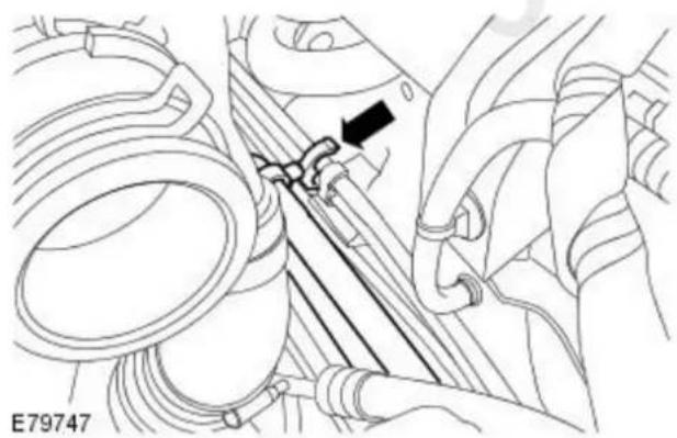
natural_image
Technical diagram of a mechanical assembly with pipes and a black arrow indicating a component (no text or symbols present)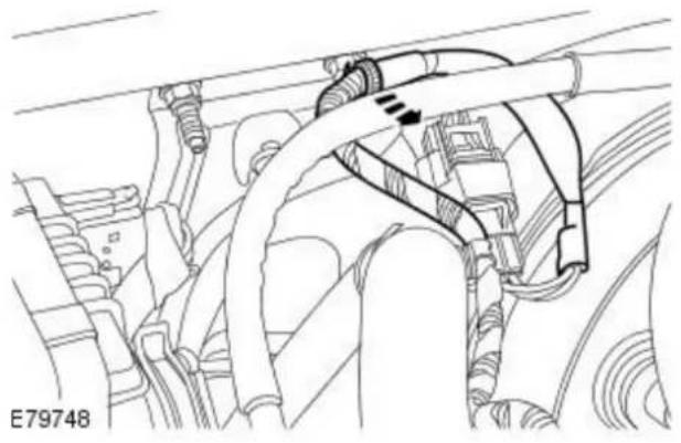
natural_image
Technical line drawing of a mechanical assembly with hoses and components (no text or symbols)- Detach the wiring harness.

- Detach the DPF differential pressure sensor retaining bracket.
- Remove the retaining nuts.

natural_image
Technical line drawing of a mechanical assembly with hoses and connectors (no text or symbols)- Disconnect the DPF differential pressure sensor electrical connector.

natural_image
Technical diagram of a mechanical assembly with hoses and connectors (no visible text or symbols)- NOTE: Note the orientation of the DPF differential pressure high-pressure and low-pressure hoses and make sure they are installed in the same position.
Disconnect the DPF differential pressure sensor high-pressure and low-pressure hoses.
All vehicles
- Remove the brake booster. For additional information, refer to: Brake Booster - RHD AWD/RHD FWD (206-07 Power Brake Actuation, Removal and Installation).
All except vehicles with diesel engine

natural_image
Mechanical assembly diagram showing engine components and a black arrow indicating a specific part (no text or symbols present)- Disconnect the upper fuel vapor hose from the evaporative emission canister purge valve.

natural_image
Technical diagram of engine components with directional arrows indicating flow or movement (no text or symbols present)- Detach the oxygen sensor electrical connectors.
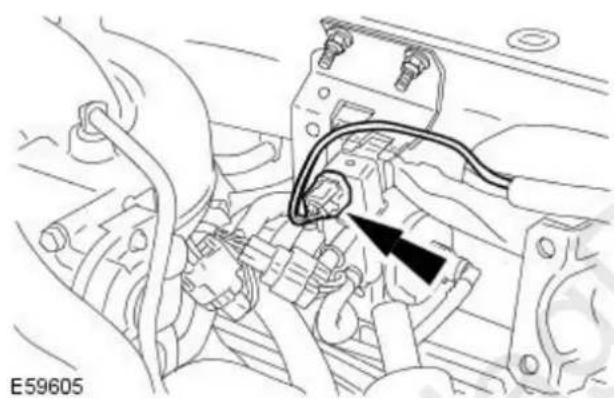
natural_image
Technical diagram of an automotive engine component with wiring and a black arrow indicating a specific part (no text or symbols present)- Disconnect the evaporator solenoid electrical connector.

natural_image
Mechanical assembly diagram showing engine components and a black arrow indicating a specific component (no text or labels present)- Disconnect the lower fuel vapor hose from the evaporative emission canister purge valve.

natural_image
Technical line drawing of a mechanical assembly with hoses and connectors (no text or symbols)- Detach the wiring harness from the retaining bracket.
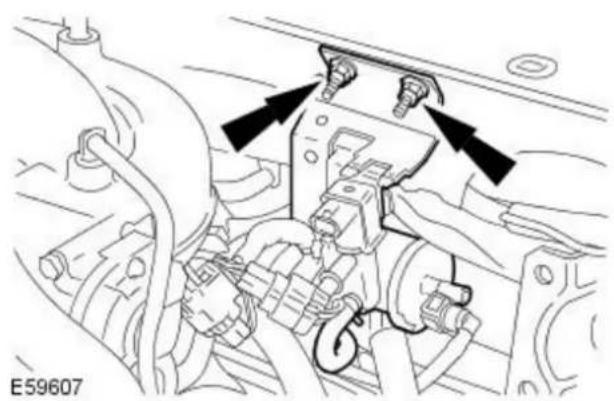
natural_image
Technical diagram of an engine assembly with directional arrows indicating components (no text or labels)- Remove the evaporative emission canister purge valve retaining bracket.
Vehicles with 2.0L engine
- Remove the intake manifold. For additional information, refer to: Intake Manifold (303-01A Engine - 2.0L NA V6 - AJV6/2.5L NA V6 - AJV6/3.0L NA V6 - AJ27, In-vehicle Repair).
All vehicles
- Remove the A/C refrigerant line retaining clip.

natural_image
Mechanical assembly diagram showing a hand operating a valve with a black arrow pointing to a component (no text or symbols present)
- NOTE: Install blanking plugs to the exposed ports.
Using the special tool, disconnect the A/C refrigerant line.
- Remove and discard the O-ring seals.
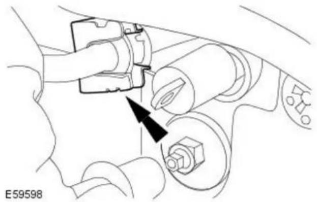
natural_image
Diagram of a car's internal components with a black arrow pointing to a component, no text or symbols present.- Remove the A/C refrigerant line retaining clip.

- NOTE: Install blanking plugs to the exposed ports.
Using the special tool, disconnect the A/C refrigerant line.
- Remove and discard the O-ring seals.
All except vehicles with diesel engine

natural_image
Technical diagram of a vehicle suspension system with no visible text or symbols- NOTE: The bolt remains captive in the engine control module (ECM) electrical connector.
Using special tool 418-535, disconnect the ECM electrical connector.
Vehicles with diesel engine

- NOTE: Install blanking plugs to the fuel pump fuel supply and return line male and female connectors.
Disconnect the fuel pump fuel supply and return lines. For additional information, refer to: Quick Release Coupling - Push Connect (310-00 Fuel System - General Information, General Procedures).
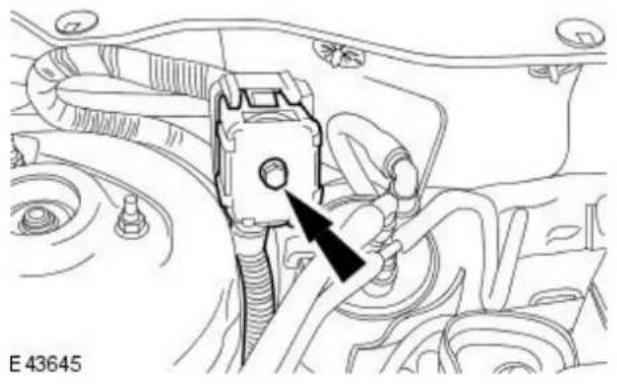
natural_image
Technical diagram of a mechanical assembly with a black arrow pointing to a component (no text or symbols present)
natural_image
Mechanical assembly diagram showing a belt drive mechanism with no visible text or symbols
natural_image
Technical diagram of an engine component with no visible text or symbols

natural_image
Technical line drawing of a mechanical assembly with no visible text or symbols- Disconnect the engine wiring harness electrical connector.
- Detach the engine wiring harness retaining clip.
- Detach the engine wiring harness electrical connector.
- NOTE: The bolt remains captive in the ECM electrical connector. Disconnect the ECM harness electrical connector.
- Detach the engine wiring harness retaining clip.
natural_image
Technical diagram of a mechanical component with a black arrow indicating a specific feature (no text or symbols present)- Remove the brake pedal cross-shaft support bracket retaining bolt.

natural_image
Technical line drawing of a mechanical component with directional arrows indicating movement (no text or symbols)- Rotate the brake pedal cross-shaft clockwise.
natural_image
Technical diagram of a mechanical assembly with a central shaft and circular components, no readable text or symbols present.-
Remove the brake pedal and bracket. For additional information, refer to: Brake Pedal and Bracket (206-06 Hydraulic Brake Actuation, Removal and Installation).
-
Remove the sound insulation.
natural_image
Diagram of a car interior showing dashboard and steering wheel (no text or symbols)- Remove the glove compartment hinge retaining screws.

- Remove the glove compartment finisher trim.
- Remove the glove compartment.
- Remove the glove compartment retaining screws.
- Remove the blower motor trim.
- Remove the central junction box (CJB) retaining nut.
- Detach the CJB.


natural_image
Technical diagram of a mechanical component with arrows indicating assembly or connection points (no text or symbols present)

-
Reposition the brake pedal cross-shaft securing bracket.
-
Undo but do not remove the brake pedal cross-shaft securing bracket retaining nut.
-
Reposition the brake pedal cross-shaft securing bracket.
-
Remove the right-hand fender splash shield. For additional information, refer to: Fender Splash Shield (501-02 Front End Body Panels, Removal and Installation).
-
Remove the refrigerant lines retaining clips.
-
NOTE: Install blanking plugs to the exposed ports.
Using the special tool, disconnect the A/C refrigerant line.
- Remove and discard the O-ring seals.
- NOTE: Install blanking plugs to the exposed ports.
Using the special tool, disconnect the A/C refrigerant line.
- Remove and discard the O-ring seals.

-
Detach the brake lines.
-
Remove the A/C refrigerant line.
- Remove the retaining clip.
-
Remove the A/C refrigerant line.
-
NOTE: Note the position of the brake pedal cross-shaft spring. Detach the brake pedal cross-shaft spring.

natural_image
Mechanical assembly diagram showing a threaded component inserted into a housing (no text or symbols visible)-
Detach the brake pedal cross-shaft left-hand mounting bracket.
-
Detach the brake pedal cross-shaft grommet.

natural_image
Diagram of a car interior showing a plug inserted into a socket, with a black arrow pointing to the socket (no text or symbols present)- NOTE: Remove the brake pedal cross-shaft spring bush. Remove the brake pedal cross-shaft.
natural_image
Mechanical assembly diagram showing a lever mechanism with no visible text or symbolsInstallation
All vehicles
- NOTE: Make sure that the brake pedal cross-shaft bush is correctly positioned.
Install the brake pedal cross-shaft.

natural_image
Mechanical assembly diagram showing a lever mechanism with no visible text or symbols- Attach the brake pedal cross-shaft grommet.

natural_image
Technical line drawing of a car electrical plug socket with a black arrow indicating a component (no text or symbols present)- Attach the brake pedal cross-shaft left-hand mounting bracket.
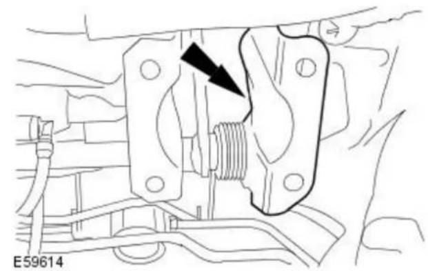
natural_image
Mechanical assembly diagram showing a threaded component inserted into a housing (no text or symbols)- NOTE: Make sure the brake pedal cross-shaft spring is located in its original position.
Attach the brake pedal cross-shaft spring.

- Install the A/C refrigerant line.

natural_image
Technical line drawing of a car interior showing engine compartment and valve (no text or symbols)- Install the A/C refrigerant line.
• Install the retaining clip.

natural_image
Technical line drawing of a car seatbelt mechanism with no visible text or symbols
natural_image
Technical diagram of a mechanical assembly with arrows indicating direction (no text or symbols present)- Attach the brake lines.

natural_image
Technical diagram of a mechanical assembly with no visible text or symbols- NOTE: Remove the blanking plugs.
Connect the A/C refrigerant line.
• Install new O-ring seals.

natural_image
Technical diagram of a mechanical assembly with springs and a valve, no visible text or symbols- NOTE: Remove the blanking plugs.
Connect the A/C refrigerant line.
• Install new O-ring seals.

natural_image
Technical diagram of a mechanical assembly with arrows indicating components (no readable text or symbols)-
Install the A/C refrigerant lines retaining clips.
-
Install the right-hand fender splash shield. For additional information, refer to: Fender Splash Shield (501-02 Front End Body Panels, Removal and Installation).


natural_image
Diagram of a vehicle's internal components with an arrow pointing to a specific part (no text or symbols present)
natural_image
Diagram of a mechanical or electrical component with coiled wires and a black arrow pointing to a central component (no text or symbols present)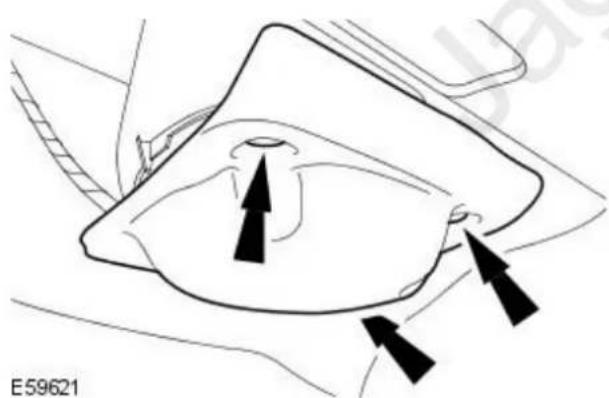
natural_image
Diagram of a car intake manifold with directional arrows indicating flow or movement (no text or symbols)
natural_image
Top-down view of a car interior showing dashboard and rearview (no text or symbols)-
Reposition the brake pedal cross-shaft securing bracket.
-
Tighten the brake pedal cross-shaft securing bracket retaining nut.
-
Reposition the brake pedal cross-shaft securing bracket.
-
Attach the CJB.
- Tighten to 6 Nm.
- Install the CJB retaining nut.
- Tighten to 6 Nm.
-
Install the blower motor trim.
-
Install the glove compartment.
• Install the passenger compartment retaining screws.
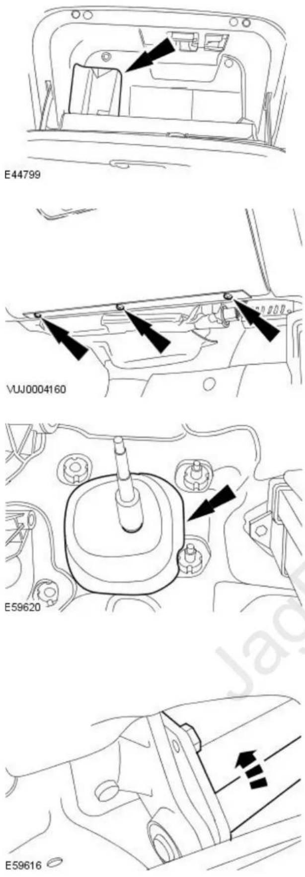
- Install the glove compartment finisher trim.
- Install the glove compartment hinge retaining screws.
- Install the sound insulation.
- Install the pedal box. For additional information, refer to: Brake Pedal and Bracket (206-06 Hydraulic Brake Actuation, Removal and Installation).
- Rotate the brake pedal cross-shaft counter-clockwise.
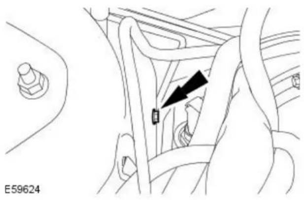
natural_image
Technical line drawing of a car interior showing a valve and adjustment knob (no text or symbols)- Install the brake pedal cross-shaft support bracket retaining bolt.
- Tighten to 25 Nm.
All except vehicles with diesel engine
- Connect the ECM electrical connector.
• Using special tool 418-535, tighten to 5 Nm.

natural_image
Technical line drawing of a mechanical assembly with no visible text or symbolsVehicles with diesel engine
- Attach the engine wiring harness retaining clip.

natural_image
Technical line drawing of a mechanical assembly with no visible text or symbols- Connect the ECM electrical connector.
- Tighten to 5 Nm.
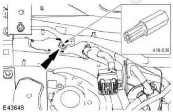
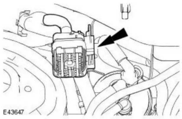
natural_image
Technical diagram of an automotive engine component with no visible text or symbols- Attach the engine wiring harness electrical connector.
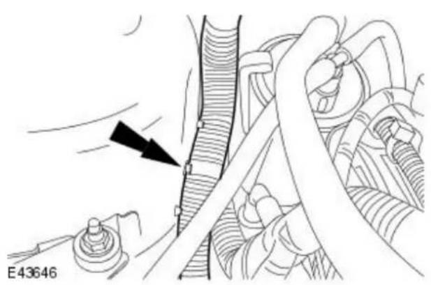
natural_image
Mechanical assembly diagram showing a lever mechanism with a black arrow indicating motion direction (no text or symbols present)- Attach the engine wiring harness retaining clip.
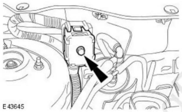
natural_image
Technical diagram of an engine component with a black arrow pointing to a keyway (no text or symbols present)- Connect the engine wiring harness electrical connector.
- Tighten to 10 Nm.

- NOTE: Remove the blanking plugs from the fuel pump fuel supply and return line male and female connectors.
Connect the fuel pump fuel supply and return lines. For additional information, refer to: Quick Release Coupling - Push Connect (310-00 Fuel System - General Information, General Procedures).
All vehicles

natural_image
Mechanical assembly diagram showing a shaft and nut assembly with a black arrow indicating direction (no text or symbols)- NOTE: Remove the blanking plugs.
Connect the A/C refrigerant line.
• Install new O-ring seals.
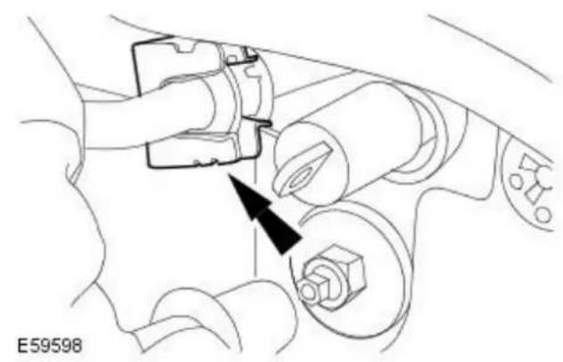
natural_image
Mechanical assembly diagram showing a belt switch connected to a component with a black arrow indicating direction (no text or symbols present)- Install the A/C refrigerant line retaining clip.
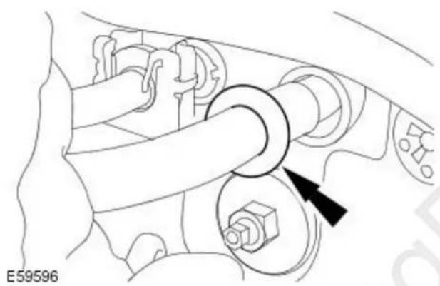
natural_image
Mechanical assembly diagram showing a valve mechanism with a black arrow indicating direction (no text or symbols present)- NOTE: Remove the blanking plugs.
Connect the A/C refrigerant line.
• Install new O-ring seals.

natural_image
Mechanical assembly diagram showing a valve or connector with a black arrow pointing to a component (no text or symbols present)- Install the refrigerant line retaining clip.
Vehicles with 2.0L engine
- Install the intake manifold.
For additional information, refer to: Intake Manifold (303-01A Engine - 2.0L NA V6 - AJV6/2.5L NA V6 - AJV6/3.0L NA V6 - AJ27, In-vehicle Repair).
All except vehicles with diesel engine

natural_image
Technical diagram of an automotive engine assembly showing valve and gear components with directional arrows (no text or labels)- Install the evaporative emission canister purge valve retaining bracket.
• Install the retaining nuts.
- Tighten to 5 Nm.

natural_image
Technical line drawing of a mechanical assembly with hoses and connectors (no text or symbols)- Attach the wiring harness to the retaining bracket.

natural_image
Technical line drawing of a mechanical assembly with no visible text or symbols- Connect the lower fuel vapor hose to the evaporative emission canister purge valve.
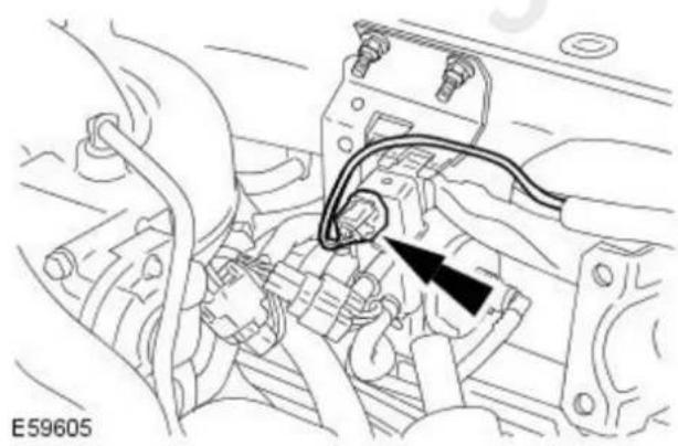
natural_image
Technical line drawing of an engine component with wiring and a black arrow indicating a specific part (no text or symbols present)- Connect the evaporator solenoid electrical connector.
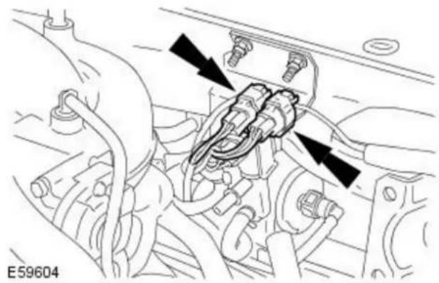
natural_image
Mechanical assembly diagram showing engine components with directional arrows indicating movement or force (no text labels)- Attach the oxygen sensor electrical connectors.
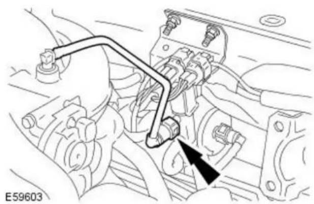
natural_image
Mechanical assembly diagram showing engine components and a directional arrow (no text or labels)- Connect the upper fuel vapor hose to the evaporative emission canister purge valve.
All vehicles
- Install the brake booster.
For additional information, refer to: Brake Booster - RHD AWD/RHD FWD (206-07 Power Brake Actuation, Removal and Installation).
Vehicles with diesel particulate filter

natural_image
Technical line drawing of a mechanical assembly with hoses and connectors (no text or symbols)- NOTE: Note the orientation of the DPF differential pressure high-pressure and low-pressure hoses and make sure they are installed in the same position.
Connect the DPF differential pressure sensor high-pressure and low-pressure hoses.

natural_image
Technical line drawing of a mechanical assembly with hoses and connectors (no text or symbols)- Connect the DPF differential pressure sensor electrical connector.
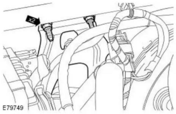

natural_image
Technical diagram of a mechanical assembly with hoses and connectors (no text or symbols visible)
natural_image
Technical line drawing of a mechanical assembly with pipes and a black arrow indicating a component (no text or symbols present)- Attach the DPF differential pressure sensor retaining bracket.
• Install the retaining nuts.
- Tighten to 5 Nm.
-
Attach the wiring harness.
-
CAUTION: Install the retaining clip to the original position. Failure to follow this instruction may result in damage to the vehicle.
Attach the the DPF high-pressure and low-pressure hoses.
-
Install the air cleaner outlet pipe. For additional information, refer to: Air Cleaner Outlet Pipe (303-12B Intake Air Distribution and Filtering - 2.0L Duratorq-TDCi/2.2L Duratorq-TDCi (110kW/150PS) - Puma, Removal and Installation).
-
Recharge the A/C refrigerant. For additional information, refer to: Air Conditioning (A/C) System Recovery, Evacuation and Charging (412-00 Climate Control System - General Information, General Procedures).
-
Connect the battery ground cable. For additional information, refer to: Battery Connect (414-01 Battery, Mounting and Cables, General Procedures).
All vehicles
Torque Specifications
| Description Nm lb-ft lb-in | |||
| Brake booster retaining nuts 25 18 - | |||
| Brake master cylinder retaining nuts 25 18 - | |||
| Coolant expansion tank retaining bolt 3 - 27 | |||
| Speed control module retaining bolt - Vehicles with 2.0L engine 4 - 35 | |||
| Vacuum pump retaining nuts - Vehicles with 2.0L engine 10 - 89 | |||
| Vacuum pump retaining bolts - Vehicles with diesel engine | 23 | 17 - |
Power Brake Actuation - Brake Booster
Description and Operation

WARNING: Brake fluid contains polyglycol ethers and polyglycols. Avoid contact with eyes. Wash hands after handling. If brake fluid contacts the eyes, flush the eyes for 15 minutes with cold running water. Get medical attention if irritation persists. If taken internally, drink water and induce vomiting. Get medical attention immediately. Failure to follow these instructions may result in personal injury.

VUJ0003042
| Item Part Number Description | |
| 1 — Brake fluid reservoir filler cap | |
| 2 — Brake fluid reservoir | |
| 3 — Brake fluid low level warning indicator | |
| 4 — Brake master cylinder | |
| 5 — Brake booster | |
| 6 — Brake booster vacuum hose grommet |
The diaphragm type power brake booster:
- is self contained.
- is mounted on the engine side of the bulkhead.
- uses engine intake manifold vacuum, vacuum pump and atmospheric pressure for its assistance.
- is connected to a manifold vacuum hose with a built in non return valve.
Power Brake Actuation - Power Brake System
Diagnosis and Testing
For additional information, refer to Section 206-00 Brake System - General Information.
Power Brake Actuation - Brake BoosterLHD AWD/ LHD FWD
Removal and Installation
Removal
All vehicles

-
Remove the brake booster push rod retaining clip.
-
Release the brake booster push rod retaining clip.
- Remove the brake booster push rod retaining clip.

natural_image
Technical line drawing of a car engine component with a black arrow pointing to a cable or connector (no text or symbols present)- Disconnect the brake fluid low level warning indicator electrical connector.

natural_image
Technical diagram of a car engine component with no visible text or symbols- Detach the brake fluid low level warning indicator wiring harness from the coolant expansion tank.

natural_image
Technical diagram of a vehicle engine compartment with two black arrows pointing to specific components (no text or labels present)- NOTE: Install blanking plugs to the cooling system vent hoses and the coolant expansion tank.
Detach the cooling system vent hoses from the coolant expansion tank.

natural_image
Technical diagram of a mechanical assembly with no visible text or symbols- Remove the coolant expansion tank retaining bolt.

-
Reposition the coolant expansion tank.
-
Detach the coolant expansion tank.
- Reposition the coolant expansion tank.
Vehicles with 2.0L engine
- Detach the cruise control cable.

natural_image
Mechanical assembly diagram showing a lever mechanism with no visible text or symbols
-
Detach the throttle cable.
-
Reposition the throttle lever to the fully open position.
- Detach the throttle cable.
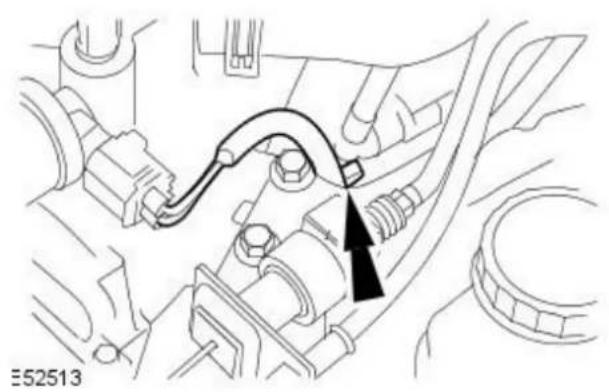
natural_image
Technical diagram of a mechanical assembly with no visible text or symbols- Detach the idle air control (IAC) valve wiring harness.

natural_image
Technical diagram of a mechanical assembly with two circular components and directional arrows indicating motion (no text or symbols)- Detach the throttle cable retaining bracket.
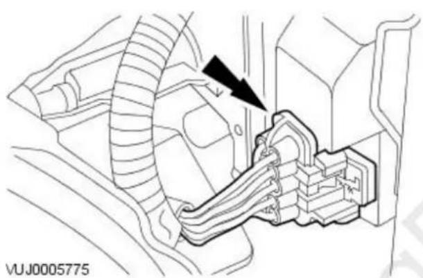
natural_image
Technical diagram of a mechanical assembly with no visible text or symbols- Disconnect the speed control module electrical connector.

natural_image
Technical line drawing of a mechanical component with a bolt and arrow indicator (no text or symbols)- Remove the speed control module retaining bolt.
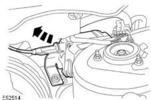
natural_image
Technical diagram of a car engine compartment showing valve and hub assembly (no text or labels)- Reposition the speed control module.
Vehicles with manual transmission
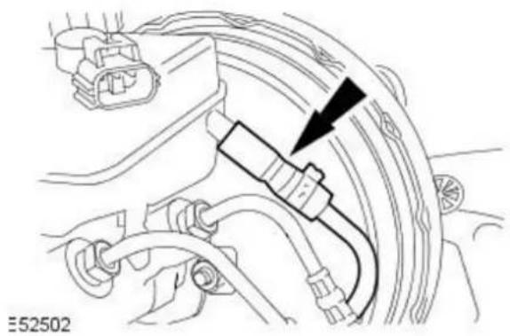
natural_image
Technical diagram of an automotive electrical connector with cable and wiring (no text or symbols)- CAUTION: If brake fluid is split on the paintwork, the affected area must be immediately washed down with cold water. Failure to follow this instruction may result in damage to the vehicle.
- NOTE: Install blanking plugs to the clutch master cylinder feed hose and the brake fluid reservoir.
Detach the clutch master cylinder feed hose.
All vehicles

natural_image
Technical line drawing of a mechanical assembly with no visible text or symbols- Detach the brake fluid supply tubes from the retaining clip.
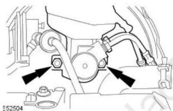
natural_image
Mechanical assembly diagram showing a motor and gear assembly with no visible text or symbols- Detach the brake master cylinder assembly from the brake booster.
- Remove and discard the O-ring seal at the rear of the brake master cylinder.
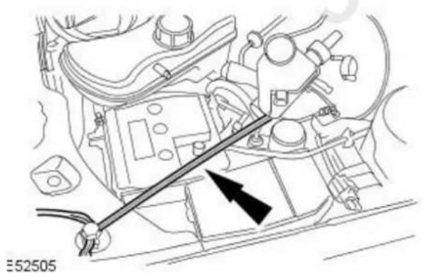
natural_image
Technical diagram of an engine component with a tool and arrow indicating assembly direction (no text or symbols present)- Using a suitable cord, reposition the brake master cylinder assembly.
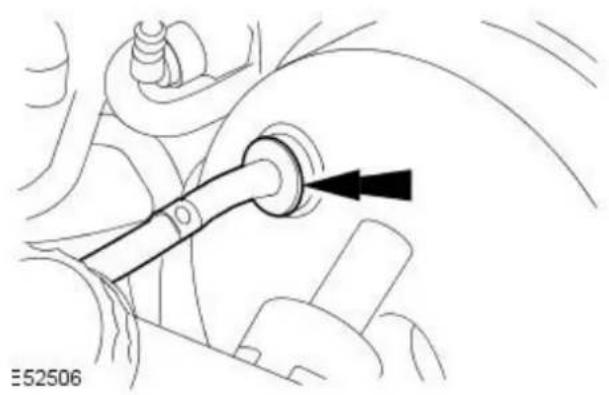
natural_image
Mechanical assembly diagram showing a pipe with a black arrow indicating direction (no text or symbols)- Detach the brake booster vacuum hose.

natural_image
Diagram of a car engine bay with directional arrows indicating flow or movement (no text or symbols present)- Detach the brake booster.
- Remove the brake booster retaining nuts.

natural_image
Technical line drawing of a mechanical component with a black arrow pointing to a detail (no text or symbols present)- Remove the brake booster support bracket.

natural_image
Technical line drawing of a mechanical component with no visible text or symbols- Remove the brake booster.
Installation
All vehicles
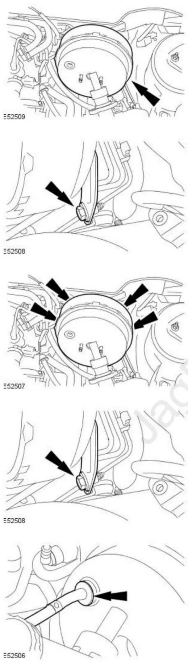
- NOTE: Make sure the brake booster push rod is correctly aligned to the brake pedal.
-
NOTE: Do not install the brake booster retaining nuts at this stage. Install the brake booster.
-
Install the brake booster support bracket.
- Loosely install the brake booster support bracket retaining bolt.
- Attach the brake booster.
- Tighten to 25 Nm.
-
Tighten the brake booster support bracket retaining bolt.
-
Attach the brake booster vacuum hose.

natural_image
Mechanical assembly diagram showing a motor and gear assembly with directional arrows indicating motion (no text or symbols)- NOTE: Install a new brake master cylinder to brake booster O-ring seal.
- NOTE: Make sure the brake booster push rod is correctly aligned to the brake master cylinder assembly.
Attach the brake master cylinder assembly to the brake booster.
- Tighten to 25 Nm.

natural_image
Technical diagram of a vehicle's engine and suspension system, showing mechanical components and alignment arrows (no text or symbols)- Attach the brake fluid supply tubes to the retaining clip.
Vehicles with manual transmission
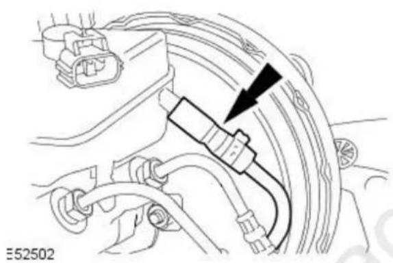
natural_image
Technical line drawing of a mechanical assembly with no visible text or symbols- CAUTION: If brake fluid is split on the paintwork, the affected area must be immediately washed down with cold water. Failure to follow this instruction may result in damage to the vehicle.
- NOTE: Remove the blanking plugs from the clutch master cylinder feed hose and the brake fluid reservoir.
Attach the clutch master cylinder feed hose.
Vehicles with 2.0L engine
- Reposition the speed control module.

natural_image
Technical line drawing of a car engine compartment with no visible text or symbols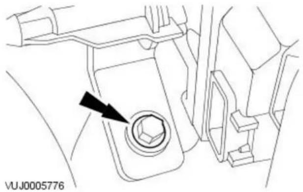
natural_image
Technical line drawing of a vehicle interior showing a bolt and valve (no text or symbols)- Install the speed control module retaining bolt.
- Tighten to 4 Nm.

natural_image
Technical diagram of a mechanical assembly with labeled components and an arrow indicating direction (no readable text or symbols)- Connect the speed control module electrical connector.
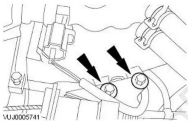
natural_image
Technical diagram of a mechanical assembly with two bolted components and directional arrows indicating motion (no text or symbols)- Attach the throttle cable retaining bracket.

natural_image
Technical diagram of a mechanical assembly with no visible text or symbols- Attach the IAC valve wiring harness.

-
Attach the throttle cable.
-
Reposition the throttle lever to the fully open position.
- Attach the throttle cable.

natural_image
Mechanical assembly diagram showing a lever mechanism with no visible text or symbolsAll vehicles
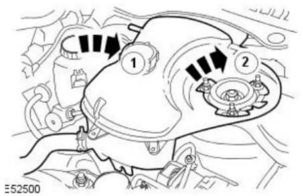

natural_image
Technical line drawing of a mechanical assembly with no visible text or symbols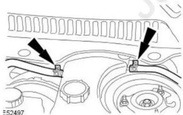
-
Attach the cruise control cable.
-
Attach the coolant expansion tank.
-
Reposition the coolant expansion tank.
-
Attach the coolant expansion tank.
-
Install the coolant expansion tank retaining bolt.
- Tighten to 3 Nm.
- NOTE: Remove the blanking plugs from the cooling system vent hoses and the coolant expansion tank.
Attach the cooling system vent hoses to the coolant expansion tank.

natural_image
Technical diagram of a car engine component with no visible text or symbols- Attach the brake fluid low level warning indicator wiring harness to the coolant expansion tank.
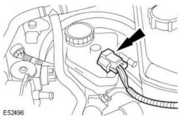
natural_image
Technical diagram of a vehicle engine component with hoses and a black arrow pointing to a cable (no text or symbols present)- Connect the brake fluid low level warning indicator electrical connector.

natural_image
Mechanical assembly diagram showing a valve mechanism with no visible text or symbols-
Install the brake booster push rod retaining clip.
-
Check and top up the cooling system as required.
Vehicles with manual transmission
- Bleed the clutch system. For additional information, refer to: Clutch System Bleeding - Vehicles With: 6-Speed Manual Transaxle - MMT6 (308-00 Manual Transmission/Transaxle and Clutch - General Information, General Procedures).
Power Brake Actuation - Brake BoosterRHD AWD/ RHD FWD
Removal and Installation
| Special Tool(s) | |
| JDS9013 | Brake pedal hold down tool JDS 9013 |
Removal
All vehicles

natural_image
Technical diagram of a car engine component with hoses and a valve, no visible text or symbols- Disconnect the brake fluid low level warning indicator electrical connector.

natural_image
Technical diagram of a car engine component with no visible text or symbols- Detach the brake fluid low level warning indicator wiring harness from the coolant expansion tank.
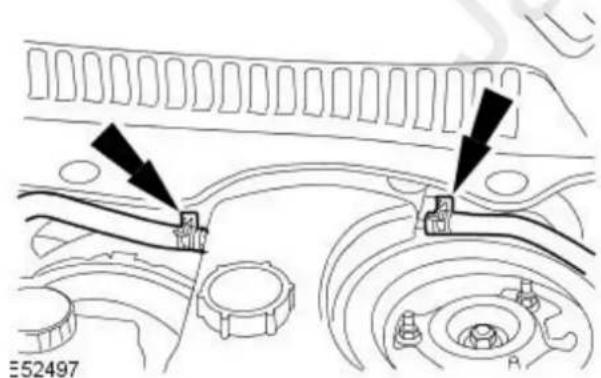
- NOTE: Install blanking plugs to the cooling system vent hoses and the coolant expansion tank.
Detach the cooling system vent hoses from the coolant expansion tank.

natural_image
Technical diagram of a mechanical assembly with no visible text or symbols
-
Remove the coolant expansion tank retaining bolt.
-
Reposition the coolant expansion tank.
-
Detach the coolant expansion tank.
- Reposition the coolant expansion tank.
Vehicles with 2.0L engine
- Detach the cruise control cable.
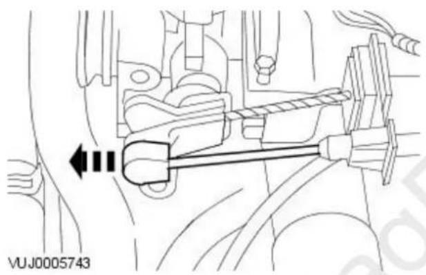
natural_image
Mechanical assembly diagram showing a lever mechanism with no visible text or symbols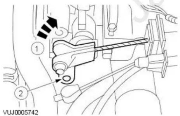
-
Detach the throttle cable.
-
Reposition the throttle lever to the fully open position.
- Detach the throttle cable.
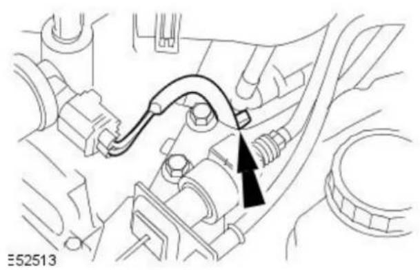
natural_image
Technical diagram of a mechanical assembly with no visible text or symbols- Detach the idle air control (IAC) valve wiring harness.

natural_image
Technical diagram of a mechanical assembly with two circular components and directional arrows indicating motion (no text or symbols)- Detach the throttle cable retaining bracket.

natural_image
Technical diagram of a mechanical assembly with no visible text or symbols- Disconnect the speed control module electrical connector.

natural_image
Technical line drawing of a mechanical component with a bolt and arrow indicator (no text or symbols)- Remove the speed control module retaining bolt.

natural_image
Mechanical component diagram showing engine and dashboard assembly with no visible text or symbols- Reposition the speed control module.
Vehicles with manual transmission

natural_image
Technical diagram of an automotive electrical connector with cable and wiring (no text or symbols)- CAUTION: If brake fluid is split on the paintwork, the affected area must be immediately washed down with cold water. Failure to follow this instruction may result in damage to the vehicle.
- NOTE: Install blanking plugs to the clutch master cylinder feed hose and the brake fluid reservoir.
Detach the clutch master cylinder feed hose.
All vehicles

natural_image
Technical line drawing of a mechanical assembly with no visible text or symbols- Detach the brake fluid supply tubes from the retaining clip.
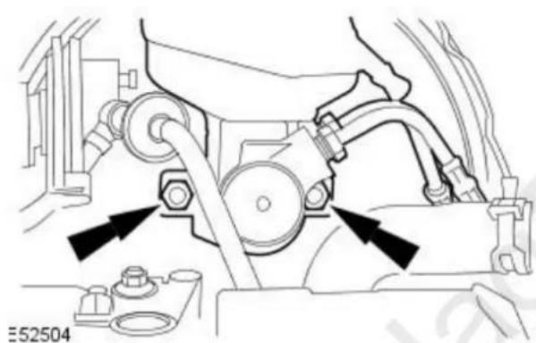
natural_image
Mechanical assembly diagram showing a motor and gear assembly with no visible text or symbols- Detach the brake master cylinder assembly from the brake booster.
- Remove and discard the O-ring seal at the rear of the brake master cylinder.

natural_image
Technical diagram of an engine component with a tool and arrow indicating assembly direction (no text or symbols present)- Using a suitable cord, reposition the brake master cylinder assembly.

natural_image
Mechanical assembly diagram showing a pipe with a black arrow indicating direction (no text or symbols)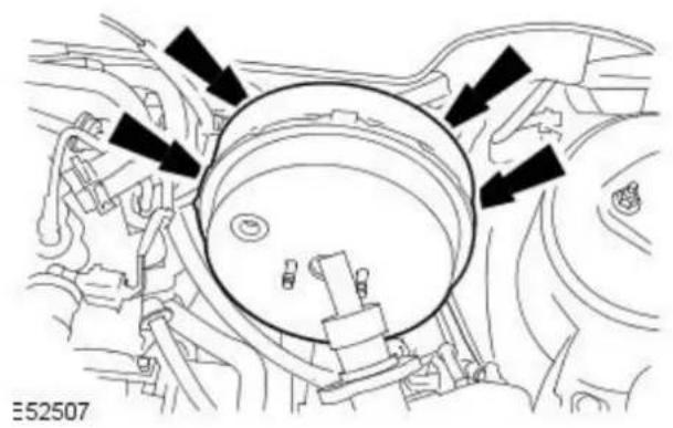
natural_image
Diagram of a car engine bay with directional arrows indicating flow or movement (no text or symbols present)
natural_image
Technical line drawing of a mechanical assembly with a black arrow pointing to a component (no text or symbols present)
natural_image
Technical line drawing of a mechanical assembly with no visible text or symbolsVUJ0003217
-
Detach the brake booster vacuum hose.
-
Detach the brake booster.
- Remove the brake booster retaining nuts.
-
Remove the brake booster support bracket.
-
Using the brake pedal hold down tool, apply the brake pedal until the brake booster push rod pin can be removed.
-
Remove the brake booster push rod pin retaining clip.

natural_image
Technical line drawing of a mechanical assembly with a hand fastening a bolt (no text or symbols)VUJ0003218
- Remove the brake booster push rod pin.

natural_image
Technical line drawing of a car engine bay with a circular component and directional arrow (no text or symbols)- Remove the brake booster.
Installation
All vehicles

natural_image
Technical diagram of a car engine bay with a circular component and directional arrow (no text or symbols)- NOTE: Do not install the brake booster retaining nuts at this stage. Install the brake booster.

natural_image
Technical line drawing of a mechanical assembly with two components and directional arrows indicating motion (no text or symbols)- Install the brake booster push rod pin.
VUJ0003220
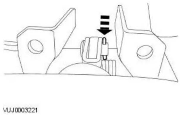
natural_image
Technical line drawing of a mechanical clamp or bracket assembly with a downward arrow indicating motion (no text or symbols)
natural_image
Technical line drawing of a mechanical assembly with a black arrow pointing to a component (no text or symbols present)
natural_image
Technical diagram of a mechanical component with arrows indicating direction (no text or symbols present)
natural_image
Technical line drawing of a mechanical component with a black arrow pointing to a detail (no text or symbols present)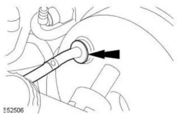
natural_image
Mechanical assembly diagram showing a pipe fitting with a black arrow indicating direction (no text or symbols)-
Install the brake booster push rod pin retaining clip.
-
Remove the brake pedal hold down tool.
- Install the brake booster support bracket.
- Loosely install the brake booster support bracket retaining bolt.
- Attach the brake booster.
- Tighten to 25 Nm.
- Tighten the brake booster support bracket retaining bolt.
- Attach the brake booster vacuum hose.

natural_image
Mechanical assembly diagram showing a belt drive mechanism with arrows indicating motion direction (no text or symbols)- NOTE: Install a new brake master cylinder to brake booster O-ring seal.
- NOTE: Make sure the brake booster push rod is correctly aligned to the brake master cylinder assembly.
Attach the brake master cylinder assembly to the brake booster.
- Tighten to 25 Nm.
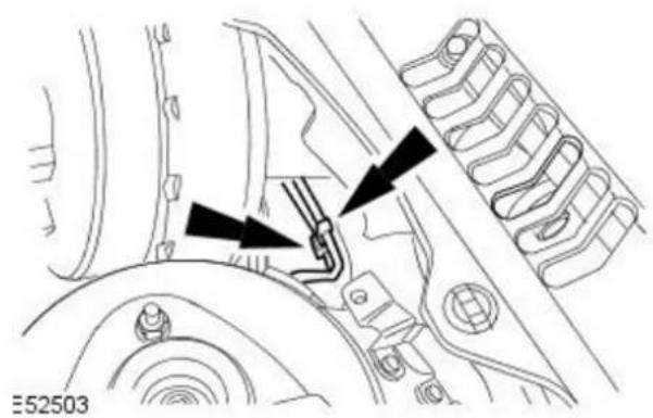
natural_image
Technical diagram of a mechanical assembly with no visible text or symbols- Attach the brake fluid supply tubes to the retaining clip.
Vehicles with manual transmission
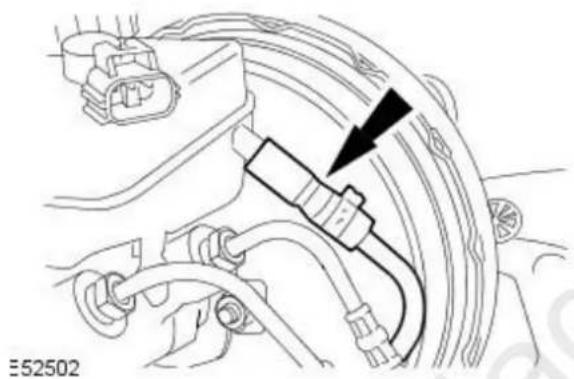
natural_image
Technical line drawing of a car engine component with hoses and wiring (no text or symbols)- CAUTION: If brake fluid is split on the paintwork, the affected area must be immediately washed down with cold water. Failure to follow this instruction may result in damage to the vehicle.
- NOTE: Remove the blanking plugs from the clutch master cylinder feed hose and the brake fluid reservoir.
Attach the clutch master cylinder feed hose.
Vehicles with 2.0L engine
- Reposition the speed control module.
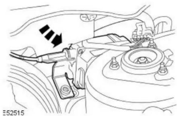
natural_image
Technical diagram of a car engine compartment showing valve and hub assembly (no text or labels)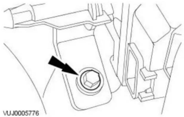
natural_image
Technical line drawing of a vehicle interior showing a bolt and valve (no text or symbols)
natural_image
Technical diagram of a mechanical assembly with labeled components and an arrow indicating direction (no readable text or symbols)
natural_image
Technical diagram of a mechanical assembly with two bolted components and directional arrows indicating motion (no text or symbols)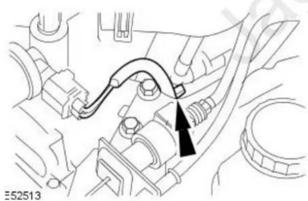
natural_image
Technical diagram of a mechanical assembly with no visible text or symbols
- Install the speed control module retaining bolt.
- Tighten to 4 Nm.
-
Connect the speed control module electrical connector.
-
Attach the throttle cable retaining bracket.
-
Attach the IAC valve wiring harness.
-
Attach the throttle cable.
-
Reposition the throttle lever to the fully open position.
- Attach the throttle cable.

natural_image
Mechanical assembly diagram showing a lever mechanism with no visible text or symbolsAll vehicles

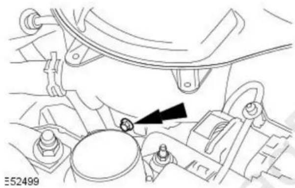
natural_image
Technical diagram of a mechanical assembly with no visible text or symbols
-
Attach the cruise control cable.
-
Attach the coolant expansion tank.
-
Reposition the coolant expansion tank.
-
Attach the coolant expansion tank.
-
Install the coolant expansion tank retaining bolt.
- Tighten to 3 Nm.
- NOTE: Remove the blanking plugs from the cooling system vent hoses and the coolant expansion tank.
Attach the cooling system vent hoses to the coolant expansion tank.
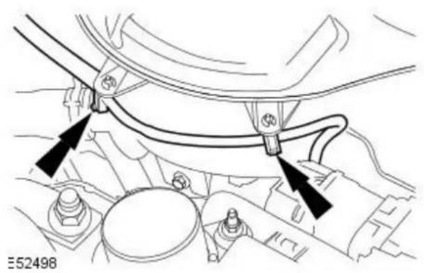
natural_image
Technical diagram of a car engine component with no visible text or symbols
natural_image
Technical diagram of an automotive engine component with a black arrow pointing to a plug or connector (no text or symbols present)-
Attach the brake fluid low level warning indicator wiring harness to the coolant expansion tank.
-
Connect the brake fluid low level warning indicator electrical connector.
-
Check and top up the cooling system as required.
Vehicles with manual transmission
- Bleed the clutch system.
For additional information, refer to: Clutch System Bleeding - Vehicles With: 6-Speed Manual Transaxle - MMT6 (308-00 Manual
Transmission/Transaxle and Clutch - General Information, General Procedures).
Power Brake Actuation - Brake Vacuum Pump2.0L NA V6 - AJV6
Removal and Installation
Removal

natural_image
Technical line drawing of a mechanical assembly with no visible text or symbols- Disconnect the vacuum hose.
- Release the retaining clip.

natural_image
Technical line drawing of a mechanical component with a black arrow pointing to a feature, no readable text or symbols present.- Disconnect the electrical connector.

natural_image
Technical line drawing of a mechanical component with arrows indicating assembly or adjustment points (no text or symbols present)- Remove the vacuum pump.
Installation

natural_image
Technical line drawing of a mechanical assembly with no visible text or symbols- To install, reverse the removal procedure.
- Tighten to 25 Nm.
Power Brake Actuation - Brake Vacuum Pump2.0L Duratorq-TDCi/ 2.2L Duratorq-TDCi (110kW/ 150PS) - Puma
Removal and Installation
| Special Tool(s) | |
 | Remover/Install, Cooling Hose Clamp303-397 |
Removal
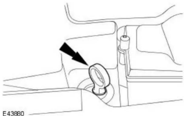
natural_image
Technical line drawing of a mechanical component with a black arrow indicating a directional arrow (no text or symbols present)- Remove the oil level indicator.

- Remove the oil filler cap.

natural_image
Technical line drawing of a mechanical component with an upward arrow and three horizontal lines (no text or symbols)-
Remove the engine cover.
-
Drain the cooling system.
For additional information, refer to: Cooling System Draining, Filling and Bleeding (303-03B Engine Cooling - 2.0L Duratorq-TDCi/2.2L Duratorq-TDCi (110kW/150PS) - Puma, General Procedures). - Remove the air cleaner outlet pipe.
For additional information, refer to: Air Cleaner Outlet Pipe (303-12B Intake Air Distribution and Filtering - 2.0L Duratorq-TDCi/2.2L Duratorq-TDCi (110kW/150PS) - Puma, Removal and Installation).
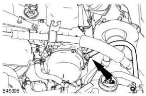
natural_image
Technical line drawing of an engine assembly with hoses and a valve (no text or symbols)
natural_image
Technical line drawing of a mechanical assembly with no visible text or symbols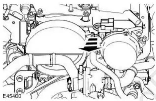
natural_image
Technical line drawing of a mechanical assembly with no visible text or symbols
natural_image
Technical line drawing of a mechanical assembly with no visible text or symbols
natural_image
Mechanical assembly diagram showing engine components and a black arrow indicating a specific part (no text or symbols present)-
Disconnect the brake vacuum hose from the brake vacuum pump.
-
Remove the power steering hose support bracket.
-
Detach the cylinder head temperature (CHT) sensor electrical connector away from the brake vacuum pump.
-
Using the special tool 303-397, disconnect the coolant hose.
-
Using the special tool 303-397, disconnect the coolant expansion tank hose from the brake vacuum pump.
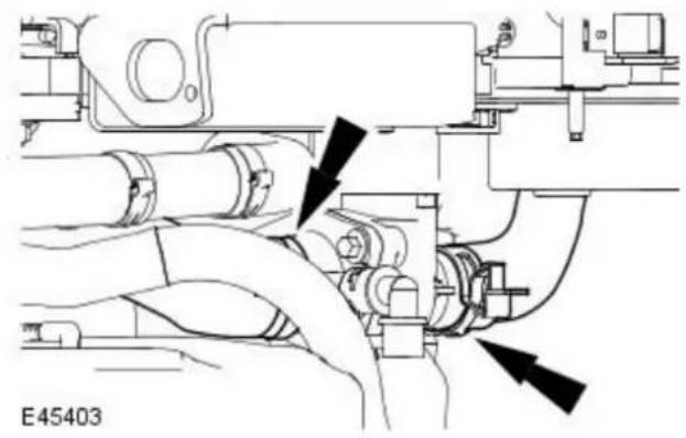
natural_image
Technical line drawing of a mechanical assembly with no visible text or symbols
natural_image
Technical line drawing of a mechanical assembly with no visible text or symbols-
Using the special tool 303-397, disconnect the coolant hoses.
-
Remove the brake vacuum pump.
- Remove and discard the gasket.
Installation
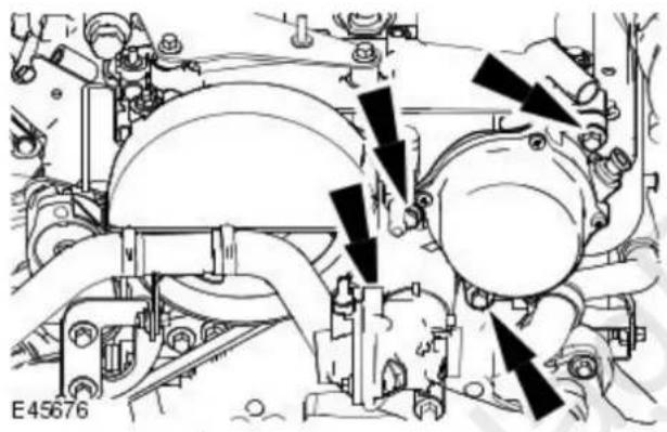
natural_image
Mechanical assembly diagram showing engine components and mounting brackets (no text or labels)- CAUTION: Make sure the drive coupling is aligned with the camshaft coupling.
- NOTE: Install a new brake vacuum pump gasket. To install, reverse the removal procedure.
- Tighten to 23 Nm.
Anti-Lock Control - Stability Assist -
Lubricants, Fluids, Sealers and Adhesives

CAUTION: Do not use brake fluid ITT Super Dot 4 on 2006my vehicles onwards. Failure to follow this instruction may result in damage or vehicle.
- NOTE: Brake fluid ITT Super Dot 4 has now been superseded by Shell ESL Super Dot 4 which is the Jaguar recommended brake fluid. Shell ESL Super Dot 4 can be used on all model years.
| Item Specification | |
| Brake fluid ITT Super Dot 4 | |
| Brake fluid Shell ESL Super Dot 4 |
Torque Specifications
| Description Nm lb-ft lb-in | |||
| Brake line connections to brake pressure control valve block 17 13 - | |||
| Steering wheel sensor securing screws 1 - 9 | |||
| Yaw rate sensor securing nut | 6 - 53 | ||
| Front wheel speed sensor securing screw | 5 - 44 | ||
| Rear wheel speed sensor securing screw - Vehicles with 2.5L and 3.0L engine | 22 16 - | ||
| Rear wheel speed sensor securing screw - Vehicles with 2.0L or diesel engine | 7 - 62 |
Anti-Lock Control - Stability Assist - Anti-Lock Control - Stability Assist
Description and Operation
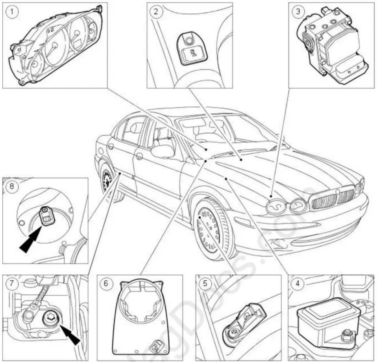
E30961
| Item Part Number Description | |
| 1 — Instrument cluster | |
| 2 - Dynamic stability control 'ON/OFF' switch | |
| 3 - ABS/Traction control hydraulic unit | |
| 4 - Yaw rate sensor | |
| 5 - Front wheel speed sensor | |
| 6 - Steering wheel angle sensor | |
| 7 - Rear wheel speed sensor + Vehicles with 2.5L and 3.0L engines | |
| 8 - Rear wheel speed sensor + Vehicles with 2.0L or diesel engines | |
The anti-lock brake system (ABS) modulates brake pressure on each wheel independently to maintain vehicle stability during braking. The ABS continually monitors the rotational velocity of each wheel anytime the ignition switch is in the RUN position and determines if a tire is loosing traction when the brakes are applied. Only then does the ABS intervene to modulate the brake pressure to the necessary wheel. The modulation continues until the wheel rotates freely. The brake pressure is then restored and the modulate/restore cycle is repeated whenever loss of traction is detected. This cycle occurs at a rate of several times per second.
The ABS module is capable of detecting the following system conditions:
• Hydraulic valve failure
- Wheel speed sensor failure
• ABS power relay short circuit
- Interconnect failures to the ABS sensors, power and ground to the ABS module
• Over/under voltage conditions
The ABS provides self-diagnostics and displays failure messages, via the ABS indicator, in the instrument cluster. Failure of the ABS module, for whatever reason, will not compromise the normal operation of the brake system.
Dynamic stability control (DSC) maximizes vehicle stability under all conditions. The DSC system compares actual vehicle course to that intended by the driver. If the intended course differs from the actual course due to over steer or under steer conditions, the DSC system will brake individual wheels and reduce engine torque to bring the vehicle back to the driver's intended direction. By using a combined yaw rate sensor and lateral accelerometer, the vehicles rotational motion around its vertical axis and centrifugal forces generated while cornering are calculated to determine the vehicle's actual behavior. Using additional sensors for detecting steering wheel position and road wheel speed
enables the system to recognize the driver's intentions.
The DSC system also incorporates emergency brake assist (EBA), which measures the rate at which the brake pressure increases during a braking manoeuvre. If the system detects an emergency braking situation, EBA automatically initiates the full braking effect. This can reduce the stopping distances in critical situations, therefore allowing an inexperienced driver to stop in the same distance as an experienced driver.
On vehicles with 2.0L or diesel engines the traction control system (TCS) is incorporated into the anti-lock brake system (ABS). On vehicles with 2.5L and 3.0L engines the traction control is an additional function added to the DSC system. The vehicles driven wheels are continually monitored for wheel spin relative to the calculated reference speed and to each other. If wheel spin is detected, the traction control function intervenes independently of the driver, applying brake pressure to the slipping wheel and reducing the engine drive torque supply. Meanwhile, brake pressure is modulated by the traction control until traction is re-established. Traction control brake actuation is diminished above 40 kph (25 mph). Above this speed traction control relies primarily on engine torque reduction.
Dynamic stability control is enabled/disabled via the DSC 'ON/OFF' switch. When the switch is in the 'OFF' position, the amber DSC warning lamp solidly illuminates within the instrument cluster message center. The DSC is automatically activated when the ignition is switched on. The DSC provides self-diagnostics also via the instrument cluster message center.
The traction control brake intervention is automatically disabled whenever the brakes exceed a temperature limit. The traction brake intervention will remain disabled until the brakes have cooled, irrespective of ignition switch position or ignition switch cycling.
Anti-Lock Control - Stability Assist - Anti-Lock Control - Stability AssistVIN Range: C00344->J12991
Diagnosis and Testing
Principle of operation
The anti-lock brake system (ABS) modulates brake pressure on each wheel independently to maintain vehicle stability during braking. The ABS continually monitors the rotational velocity of each wheel anytime the ignition switch is in the ON position and determines if a tire is skidding when the brakes are applied. Only then does the ABS intervene to modulate the brake pressure to the skidding wheel. The modulation continues until the wheel rotates freely. The brake pressure is then restored and the modulate/restore cycle is repeated whenever skidding is detected. This cycle occurs at a rate of several times per second.
The ABS module is capable of detecting the following system conditions:
- hydraulic valve failure
- wheel speed sensor failure
• ABS power relay short circuit - interconnect failures to the ABS sensors, power and ground to the ABS module
• over/under voltage conditions
The ABS provides failure messages, via the ABS indicator, in the instrument cluster. Failure of the ABS module, for whatever reason, will not compromise the normal operation of the brake system.
Dynamic Stability Control (DSC) equipped vehicles
DSC maximizes vehicle stability under all conditions. The DSC system compares actual vehicle course to that intended by the driver. If the intended course differs from the actual course due to over steer or under steer conditions, the DSC system will brake individual wheels and reduce engine torque to bring the vehicle back to the driver's intended direction. By using a combined yaw rate sensor and lateral accelerometer, the vehicles rotational motion around its vertical axis and centrifugal forces generated while cornering are calculated to determine the vehicle's actual behavior. Using additional sensors for detecting steering wheel position and road wheel speed enables the system to recognize the driver's intentions.
DSC/TCS is enabled/disabled via the DSC/TCS ON/OFF switch. When the switch is in the OFF position, the amber DSC/TCS warning lamp solidly illuminates within the instrument cluster message center. The DSC/TCS is automatically activated when the ignition is switched on. The DSC/TCS also provides failure messages via the instrument cluster message center.
On 2.0L vehicles the traction control system (TCS) is incorporated into the anti-lock brake system (ABS). Where DSC is fitted, traction control is a function within the DSC system. The vehicle's driven wheels are continually monitored for wheel spin relative to the calculated reference speed and to each other. If wheel spin is detected, the traction control function intervenes independently of the driver, applying brake pressure to the slipping wheel and reducing the engine drive torque supply. Meanwhile, brake pressure is modulated by the traction control until traction is re-established. Traction control brake actuation is diminished above 40 km/h (25 mph). Above this speed traction control relies primarily on engine torque reduction.
The traction control brake intervention is automatically disabled whenever the brakes exceed a temperature limit. The traction brake intervention will remain disabled until the brakes have cooled, irrespective of ignition switch position or ignition switch cycling.
Inspection and Verification
- Verify the customer concern.1.
- Confirm if the ABS warning light was illuminated, or still is.2.
- NOTE: An intermittent fault may allow the warning light to go off. This does not necessarily mean the fault is not present. Some warnings will appear to clear when the ignition is cycled. This is often because the warning has flagged as a result of one of the vehicle's on-board diagnostic routines having run to detect the fault. If the same routine is not run when the ignition is switched ON, the warning will not reflag until the routine does run.
-
- In order to confirm the customer concern, it may be necessary to follow a drive cycle which will enable the system to perform its diagnostic routine (see below).
Diagnostic Drive Cycles
- NOTE: See the DTC index for details of codes and possible sources/actions.
| DTC Cycle to detect fault Cycle to clear fault | System response to fault detection | ||
| C1095 Turn the ignition switch to the OFF position. Restart and drive the vehicle to activate ABS | Drive vehicle at more than 40 km/h (25 mph) for more than 2 minutes | ABS shut-down, ABS light ON, DSC/TCS shut-down, DSC/TCS light ON | |
| C1137 Turn the ignition switch to the OFF position, then ON for more than 8 minutes | Turn the ignition switch to the ON position | ABS shut-down, ABS light ON, DSC/TCS shut-down, DSC/TCS light ON | |
| C1145/C1155 /C1165/C1175 | Turn the ignition switch to the OFF position. Restart and drive the vehicle at more than 20 km/h (12.5 mph) for more than 2 minutes | Drive vehicle at more than 20 km/h (12.5 mph) | ABS shut-down, ABS light ON, DSC/TCS shut-down, DSC/TCS light ON |
| C1233/C1234 /C1235/C1236 | Turn the ignition switch to the OFF position. Restart and drive the vehicle at more than 40 km/h (25 mph) for more than 2 minutes | Drive vehicle at more than 20 km/h (12.5 mph) | ABS shut-down, ABS light ON, DSC/TCS shut-down, DSC/TCS light ON |
| C1267 Turn the ignition switch to the OFF position. Restart and drive the vehicle at more than 40 km/h (25 mph) | Turn the ignition switch to the ON position | ABS shut-down, ABS light ON, DSC/TCS shut-down, DSC/TCS light ON | |
| B1342 Turn the ignition switch to the OFF position. Restart and drive the vehicle at more than 20 km/h (12.5 mph) | Turn the ignition switch to the ON position | ABS shut-down, ABS light ON, DSC/TCS shut-down, DSC/TCS light ON | |
| B1676 Turn the ignition switch to the OFF position, then turn the ignition switch to the ON position | Turn the ignition switch to the ON position | System functions between 9 and 19 volts | |
- Visually inspect for obvious signs of mechanical or electrical damage.
| Mechanical Electrical | |
| Check the tire sizes, condition, and inflationBrake fluid level or leakageWheel speed sensor fitmentWheel speed sensor air gapWheel speed sensor toothed wheels (missing teeth/contamination) | Warning light operationFuses (see table)ABS/Traction control control unitWheel speed sensorsWheel speed sensor link leadsConnectors/pinsHarnessesGrounds |
Fuse Identification Table
| Location Fuse Number Rating Circuit | ||
| Battery junction box 05 30 Amp Vacuum module battery supply (2 ltr only) | ||
| Central junction box 67 5 Amp Vacuum module ignition supply (2 ltr only) | ||
| Battery junction box 03 60 Amp ABS/DSC/TCS module battery supply | ||
| Central junction box 96 7.5 Amp ABS/DSC/TCS module ignition supply | ||
| Central junction box 90 7.5 Amp Brake light switch circuit | ||
-
- If an obvious cause for an observed or reported concern is found, correct the cause (if possible) before proceeding to the next step.
-
- If the cause is not visually evident and the Jaguar approved diagnostic system is not available, use a fault code reader to retrieve the fault codes before proceeding to the Diagnostic Trouble Code (DTC) Index Chart.
DTC Index
| DTC | Description Possible Source | Action | |
| C1095 | Pump motor circuit fault | Pump motor circuit; open circuit, short circuit, high resistancePump motor failurePump motor power supply circuit; open circuit, short circuit to GROUNDPump motor GROUND circuit; open circuit | The pump motor is internal to the control module. For pump circuit tests, GO to Pinpoint Test I. Please check part is not on any form of prior authorisation before replacement. |
| C1137 | Control module circuit failure | Control module failure Please check | part is not on any form of prior authorisation before replacement. |
| C1145 | Right-hand front wheel speed sensor (WSS) circuit failure | Wheel speed sensor circuit(s); open circuit, short circuit | For right-hand front WSS circuit tests, GO to Pinpoint Test A._ |
| C1155 | Left-hand front wheel speed sensor (WSS) circuit failure | Wheel speed sensor circuit(s); open circuit, short circuit | For left-hand front WSS circuit tests, GO to Pinpoint Test B._ |
| C1165 | Right-hand rear wheel speed sensor (WSS) circuit failure | Wheel speed sensor circuit(s); open circuit, short circuit | For right-hand rear WSS circuit tests, GO to Pinpoint Test C._ |
| C1175 | Left-hand rear wheel speed sensor (WSS) circuit failure | Wheel speed sensor circuit(s); open circuit, short circuit | For left-hand rear WSS circuit tests, GO to Pinpoint Test D._ |
| C1222 | Wheel speed signal conflict | Vehicle operating with punctured tire(s)Mismatched wheel/tire sizesWheel speed sensor reluctor tooth damage - one or more wheels | Check wheel/tire sizes and conditions, check for sensor/reluctor damage. Check for associated DTCs. Clear the DTC, check the system for normal operation. |
| C1233 | Left-hand front wheel speed sensor (WSS) signal fault | Wheel speed sensor failureHarness damage/kinksIncorrect air gapContamination of the sensor wheel | Check the air gap at the left-hand front WSS, check the harness for damage/kinks. For left-hand front WSS circuit tests, GO to Pinpoint Test B_ |
| C1234 | Right-hand front wheel speed sensor (WSS) signal failure | Wheel speed sensor failureHarness damage/kinksIncorrect air gapContamination of the sensor wheel | Check the air gap at the right-hand front WSS, check the harness for damage/kinks. For right-hand front WSS circuit tests, GO to Pinpoint Test A_ |
| C1235 | Right-hand rear wheel speed sensor (WSS) signal failure | Wheel speed sensor failureHarness damage/kinksIncorrect air gapWheel speed sensor reluctor damage (AWD)Contamination of the sensor wheel | Check the air gap at the right-hand rear WSS, check for reluctor damage (AWD). Check the harness for damage/kinks. For right-hand rear WSS circuit tests, GO to Pinpoint Test C_ |
| C1236 | Left-hand rear wheel speed sensor (WSS) signal failure | Wheel speed sensor failureHarness damage/kinksIncorrect air gapWheel speed sensor reluctor damage (AWD)Contamination of the sensor wheel | Check the air gap at the left-hand rear WSS, check for reluctor damage (AWD). Check the harness for damage/kinks. For left-hand rear WSS circuit tests, GO to Pinpoint Test D_ |
| C1266 | Modulator solenoids power supply circuit fault | Power supply failure to valve relayABS modulator failureDSC modulator failure | Check the fuses and power circuit. For additional information, refer to the wiring diagrams. Please check part is not on any form of prior authorisation before replacement. |
| C1267 | Modulator valve fault | Modulator valve failure | Please check part is not on any form of prior authorisation before replacement. |
| DTC | Description Possible Source Action | ||
| C1278 | Steering angle sensor CAN message not plausible | Steering angle sensor not calibratedSteering angle sensor power supply circuit; open circuit, high resistanceSteering angle sensor failure | For steering angle sensor power supply circuit tests, GO to Pinpoint Test E. |
| C1279 | Yaw rate sensor circuit fault | Yaw rate sensor circuit; open circuit, short circuit, high resistanceYaw rate sensor CAN circuit; open circuitYaw rate sensor failure | For yaw rate sensor power supply circuit tests,GO to Pinpoint Test E._For yaw rate sensor CAN circuit tests,REFER to: Communications Network - VIN Range: E96603->J28492 (418-00 Module Communications Network, Diagnosis and Testing). |
| C1280 | Yaw rate sensor CAN message not plausible | Yaw rate sensor failure Use the Jaguar approved diagnostic system to measure the yaw rate offset. For CAN circuit tests,REFER to: Communications Network - VIN Range: E96603->J28492 (418-00 Module Communications Network, Diagnosis and Testing). | |
| C1282 | Lateral acceleration CAN message not plausible | Yaw rate sensor installationYaw rate sensor failure | Check the power supply to the sensor. For additional information, refer to the wiring diagrams. Use the Jaguar approved diagnostic system to measure the lateral accelerator signal. For CAN circuit tests,REFER to: Communications Network - VIN Range: E96603->J28492 (418-00 Module Communications Network, Diagnosis and Testing). |
| C1288 | Brake pressure sensor circuit fault | Brake pressure sensor circuit; open circuit, short circuit, high resistanceBrake pressure sensor failure | For brake pressure sensor circuit tests, GO to Pinpoint Test G._ |
| C1440 | Brake pressure signal fault | Brake pressure sensor failureControl module failure | Use the Jaguar approved diagnostic system to measure the brake pressure signals. |
| C1956 | Steering angle sensor fault | Steering angle sensor CAN circuit; open circuitSteering angle sensor failure | For CAN circuit tests,REFER to: Communications Network - VIN Range: E96603->J28492 (418-00 Module Communications Network, Diagnosis and Testing). |
| C1975 | DSC signal conflict Steering angle sensor incorrectly installedSteering angle sensor not calibrated - recalibrate using the Jaguar approved diagnostic systemSteering angle sensor failure | Check the installation of the steering angle sensor. Recalibrate as necessary. INSTALL a new sensor if necessary. | |
| B1676 | Battery voltage out of range: 9 - 16 volts | Charging system high/low voltageControl module failure | For charging system tests, REFER to: (414-00 Battery and Charging System - General Information)Charging System - 2.0L NA V6 - AJV6/2.5L NA V6 - AJV6/3.0L NA V6 - AJ27 (Diagnosis and Testing),Charging System - 2.0L Duratorq-TDCi/2.2L Duratorq-TDCi (110kW/150PS) - Puma (Diagnosis and Testing).Please check part is not on any form of prior authorisation before replacement. |
| None | Brake light switch circuit fault | Brake light switch power supply circuit faultBrake light switch to ABS/DSC module circuit faultBrake light switch fault | For brake light switch circuit tests, GO to Pinpoint Test H._ |
Pinpoint Tests
| PINPOINT TEST A : DTC C1145, C1234; RIGHT-HAND FRONT WHEEL SPEED SENSOR (WSS) CIRCUIT FAILURE | |
| CAUTION: To protect against over-voltage and static discharge, the contacts of the wheel speed sensor must not be touched by hand. | |
| NOTE: Where the Jaguar approved diagnostic system is available, use datalogger to monitor the wheel speed sensor values when driving in the straight-ahead position (all sensors should have the same value). | |
| TEST CONDITIONS | DETAILS/ RESULTS/ ACTIONS |
| A1: CHECK THE RIGHT-HAND FRONT WSS SENSOR CIRCUIT FOR HIGH RESISTANCE | |
| Make sure the ignition switch is in the OFF position. | |
| Disconnect the ABS/DSC module electrical connector, JB45/JB185. | |
| Disconnect the wheel speed sensor electrical connector, RF01. | |
| Measure the resistance between RF01, pin 02 (W) and JB45/JB185, pin 16 (WR). | |
| Is the resistance greater than 5 ohms?YesREPAIR the high resistance circuit. For additional information, refer to the wiring diagrams. CLEAR the DTC, test the system for normal operation.NoGO to A2. | |
| A2: CHECK THE RIGHT-HAND FRONT WSS SENSOR CIRCUIT FOR SHORT CIRCUIT TO BATTERY | |
| Measure the voltage between RF01, pin 02 (W) and GROUND. | |
| Is the voltage greater than 3 volts?YesREPAIR the short circuit. For additional information, refer to the wiring diagrams. CLEAR the DTC, test the system for normal operation.NoGO to A3. | |
| A3: CHECK THE RIGHT-HAND FRONT WSS SENSOR CIRCUIT FOR SHORT CIRCUIT TO GROUND | |
| Measure the resistance between RF01, pin 02 (W) and GROUND.Is the resistance less than 10,000 ohms?YesREPAIR the short circuit. For additional information, refer to the wiring diagrams. CLEAR the DTC, test the system for normal operation.NoGO to A4. | |
| A4: CHECK THE RIGHT-HAND FRONT WSS POWER CIRCUIT FOR HIGH RESISTANCE | |
| 1 Disconnect the wheel speed sensor. | |
| 2 Measure the resistance between RF01, pin 01 (R) and JB45/JB185, pin 15 (NR). | |
| Is the resistance greater than 5 ohms?YesREPAIR the high resistance circuit. For additional information, refer to the wiring diagrams. CLEAR the DTC, test the system for normal operation.NoGO to A5. | |
| A5: CHECK THE RIGHT-HAND FRONT WSS POWER CIRCUIT FOR SHORT CIRCUIT TO BATTERY | |
| 1 Measure the voltage between RF01, pin 01 (R) and GROUND. | |
| Is the voltage greater than 3 volts?YesREPAIR the short circuit. For additional information, refer to the wiring diagrams. CLEAR the DTC, test the system for normal operation.NoGO to A6. | |
| A6: CHECK THE RIGHT-HAND FRONT WSS POWER CIRCUIT FOR SHORT CIRCUIT TO GROUND | |
| 1 Measure the resistance between RF01, pin 01 (R) and GROUND. | |
| Is the resistance less than 10,000 ohms?YesREPAIR the short circuit. For additional information, refer to the wiring diagrams. CLEAR the DTC, test the system for normal operation.NoINSTALL a new WSS,REFER to: Front Wheel Speed Sensor (206-09 Anti-Lock Control - Stability Assist, Removal and Installation).CLEAR the DTC, test the system for normal operation. If the DTC is repeated, please check part is not on any form of prior authorisation before replacement. | |
| PINPOINT TEST B : DTC C1155, C1233; LEFT-HAND FRONT WHEEL SPEED SENSOR (WSS) CIRCUIT FAILURE | |
| CAUTION: To protect against over-voltage and static discharge, the contacts of the wheel speed sensor must not be touched by hand. | |
| NOTE: Where the Jaguar approved diagnostic system is available, use datalogger to monitor the wheel speed sensor values when driving in the straight-ahead position (all sensors should have the same value). | |
| TEST CONDITIONS | DETAILS/ RESULTS/ ACTIONS |
| B1: CHECK THE LEFT-HAND FRONT WSS SENSOR CIRCUIT FOR HIGH RESISTANCE | |
| Make sure the ignition switch is in the OFF position. | |
| Disconnect the ABS/DSC module electrical connector, JB45/JB185. | |
| Disconnect the wheel speed sensor electrical connector, LF01. | |
| Measure the resistance between LF01, pin 02 (W) and JB45/JB185, pin 12 (W). | |
| Is the resistance greater than 5 ohms?YesREPAIR the high resistance circuit. For additional information, refer to the wiring diagrams. CLEAR the DTC, test the system for normal operation.NoGO to B2. | |
| B2: CHECK THE LEFT-HAND FRONT WSS SENSOR CIRCUIT FOR SHORT CIRCUIT TO BATTERY | |
| Measure the voltage between LF01, pin 02 (W) and GROUND. | |
| Is the voltage greater than 3 volts?YesREPAIR the short circuit. For additional information, refer to the wiring diagrams. CLEAR the DTC, test the system for normal operation.NoGO to B3. | |
| B3: CHECK THE LEFT-HAND FRONT WSS SENSOR CIRCUIT FOR SHORT CIRCUIT TO GROUND | |
| Measure the resistance between LF01, pin 02 (W) and GROUND. | |
| Is the resistance less than 10,000 ohms?YesREPAIR the short circuit. For additional information, refer to the wiring diagrams. CLEAR the DTC, test the system for normal operation.NoGO to B4. | |
| B4: CHECK THE LEFT-HAND FRONT WSS POWER CIRCUIT FOR HIGH RESISTANCE | |
| Disconnect the wheel speed sensor. | |
| Measure the resistance between LF01, pin 01 (N) and JB45/JB185, pin 28 (N). | |
| Is the resistance greater than 5 ohms?YesREPAIR the high resistance circuit. For additional information, refer to the wiring diagrams. CLEAR the DTC, test the system for normal operation.NoGO to B5. | |
| B5: CHECK THE LEFT-HAND FRONT WSS POWER CIRCUIT FOR SHORT CIRCUIT TO BATTERY | |
| Measure the voltage between LF01, pin 01 (N) and GROUND. | |
| Is the voltage greater than 3 volts?YesREPAIR the short circuit. For additional information, refer to the wiring diagrams. CLEAR the DTC, test the system for normal operation.NoGO to B6. | |
| B6: CHECK THE LEFT-HAND FRONT WSS POWER CIRCUIT FOR SHORT CIRCUIT TO GROUND | |
| 1 Measure the resistance between LF01, pin 01 (N) and GROUND. | |
| Is the resistance less than 10,000 ohms?YesREPAIR the short circuit. For additional information, refer to the wiring diagrams. CLEAR the DTC, test the system for normal operation.NoINSTALL a new WSS,REFER to:Front Wheel Speed Sensor(206-09 Anti-Lock Control - Stability Assist, Removal and Installation).CLEAR the DTC, test the system for normal operation. If the DTC is repeated, please check part is not on any form of prior authorisation before replacement. | |
PINPOINT TEST C : DTC C1165, C1235; RIGHT-HAND REAR WHEEL SPEED SENSOR (WSS) CIRCUIT FAILURE
| TEST CONDITIONS | DETAILS/ RESULTS/ ACTIONS |
| C1: CHECK THE RIGHT-HAND REAR WSS SENSOR CIRCUIT FOR HIGH RESISTANCE | |
| Make sure the ignition switch is in the OFF position. | |
| Disconnect the ABS/DSC module electrical connector, JB45/JB185. | |
| Disconnect the wheel speed sensor electrical connector, CA60. | |
| Measure the resistance between CA60, pin 02 (WG) and JB45/JB185, pin 31 (WG). | |
| Is the resistance greater than 5 ohms?YesREPAIR the high resistance circuit. For additional information, refer to the wiring diagrams. CLEAR the DTC, test the system for normal operation.NoGO to C2. | |
| C2: CHECK THE RIGHT-HAND REAR WSS SENSOR CIRCUIT FOR SHORT CIRCUIT TO BATTERY | |
| Measure the voltage between CA60, pin 02 (WG) and GROUND. | |
| Is the voltage greater than 3 volts?YesREPAIR the short circuit. For additional information, refer to the wiring diagrams. CLEAR the DTC, test the system for normal operation.NoGO to C3. | |
| C3: CHECK THE RIGHT-HAND REAR WSS SENSOR CIRCUIT FOR SHORT CIRCUIT TO GROUND | |
| Measure the resistance between CA60, pin 02 (WG) and GROUND. | |
| Is the resistance less than 10,000 ohms?YesREPAIR the short circuit. For additional information, refer to the wiring diagrams. CLEAR the DTC, test the system for normal operation.NoGO to C4. | |
| C4: CHECK THE RIGHT-HAND REAR WSS POWER CIRCUIT FOR HIGH RESISTANCE | |
| Disconnect the wheel speed sensor. | |
| Measure the resistance between CA60, pin 01 (NG) and JB45/JB185, pin 30 (NG). | |
| Is the resistance greater than 5 ohms?YesREPAIR the high resistance circuit. For additional information, refer to the wiring diagrams. CLEAR the DTC, test the system for normal operation.NoGO to C5. | |
| C5: CHECK THE RIGHT-HAND REAR WSS POWER CIRCUIT FOR SHORT CIRCUIT TO BATTERY | |
| Measure the voltage between CA60, pin 01 (NG) and GROUND. | |
| Is the voltage greater than 3 volts?YesREPAIR the short circuit. For additional information, refer to the wiring diagrams. CLEAR the DTC, test the system for normal operation.NoGO to C6. | |
| C6: CHECK THE RIGHT-HAND REAR WSS POWER CIRCUIT FOR SHORT CIRCUIT TO GROUND | |
| Measure the resistance between CA60, pin 01 (NG) and GROUND. | |
| Is the resistance less than 10,000 ohms?YesREPAIR the short circuit. For additional information, refer to the wiring diagrams. CLEAR the DTC, test the system for normal operation.NoINSTALL a new WSS,REFER to:Rear Wheel Speed Sensor(206-09 Anti-Lock Control - Stability Assist, Removal and Installation).CLEAR the DTC, test the system for normal operation. If the DTC is repeated, please check part is not on any form of prior authorisation before replacement. | |
PINPOINT TEST D : DTC C1175, C1236; LEFT-HAND REAR WHEEL SPEED SENSOR (WSS) CIRCUIT FAILURE
| CAUTION: To protect against over-voltage and static discharge, the contacts of the wheel speed sensor must not be touched by hand. | |
| NOTE: Where the Jaguar approved diagnostic system is available, use datalogger to monitor the wheel speed sensor values when driving in the straight-ahead position (all sensors should have the same value). | |
| TEST CONDITIONS | DETAILS/ RESULTS/ ACTIONS |
| D1: CHECK THE LEFT-HAND REAR WSS SENSOR CIRCUIT FOR HIGH RESISTANCE | |
| Make sure the ignition switch is in the OFF position. | |
| Disconnect the ABS/DSC module electrical connector, JB45/JB185. | |
| Disconnect the wheel speed sensor electrical connector, CA55. | |
| Measure the resistance between CA55, pin 02 (WU) and JB45/JB185, pin 14 (WU).Is the resistance greater than 5 ohms?YesREPAIR the high resistance circuit. For additional information, refer to the wiring diagrams. CLEAR the DTC, test the system for normal operation.NoGO to D2. | |
| D2: CHECK THE LEFT-HAND REAR WSS SENSOR CIRCUIT FOR SHORT CIRCUIT TO BATTERY | |
| 1 Measure the voltage between CA55, pin 02 (WU) and GROUND. | |
| Is the voltage greater than 3 volts?YesREPAIR the short circuit. For additional information, refer to the wiring diagrams. CLEAR the DTC, test the system for normal operation.NoGO to D3. | |
| D3: CHECK THE LEFT-HAND REAR WSS SENSOR CIRCUIT FOR SHORT CIRCUIT TO GROUND | |
| 1 Measure the resistance between CA55, pin 02 (WU) and GROUND. | |
| Is the resistance less than 10,000 ohms?YesREPAIR the short circuit. For additional information, refer to the wiring diagrams. CLEAR the DTC, test the system for normal operation.NoGO to D4. | |
| D4: CHECK THE LEFT-HAND REAR WSS POWER CIRCUIT FOR HIGH RESISTANCE | |
| 1 Disconnect the wheel speed sensor. | |
| 2 Measure the resistance between CA55, pin 01 (GB) and JB45/JB185, pin 13 (GB). | |
| Is the resistance greater than 5 ohms?YesREPAIR the high resistance circuit. For additional information, refer to the wiring diagrams. CLEAR the DTC, test the system for normal operation.NoGO to D5. | |
| D5: CHECK THE LEFT-HAND REAR WSS POWER CIRCUIT FOR SHORT CIRCUIT TO BATTERY | |
| 1 Measure the voltage between CA55, pin 01 (GB) and GROUND. | |
| Is the voltage greater than 3 volts?YesREPAIR the short circuit. For additional information, refer to the wiring diagrams. CLEAR the DTC, test the system for normal operation.NoGO to D6. | |
| D6: CHECK THE LEFT-HAND REAR WSS POWER CIRCUIT FOR SHORT CIRCUIT TO GROUND | |
| 1 Measure the resistance between CA55, pin 01 (GB) and GROUND. | |
| Is the resistance less than 10,000 ohms?YesREPAIR the short circuit. For additional information, refer to the wiring diagrams. CLEAR the DTC, test the system for normal operation.NoINSTALL a new WSS,REFER to: Rear Wheel Speed Sensor (206-09 Anti-Lock Control - Stability Assist, Removal and Installation).CLEAR the DTC, test the system for normal operation. If the DTC is repeated, please check part is not on any form of prior authorisation before replacement. | |
| PINPOINT TEST E : C1278; STEERING ANGLE SENSOR PLAUSIBILITY ERROR | |
| NOTE: Calibrate the steering angle sensor, using the Jaguar approved diagnostic system where available. Calibration should be carried out at each removal of the subframe, steering rack, etc. | |
| NOTE: Where the Jaguar approved diagnostic system is available, use datalogger to monitor the steering angle sensor values when driving in the straight-ahead position. | |
| TEST CONDITIONS | DETAILS/ RESULTS/ ACTIONS |
| E1: CHECK THE POWER SUPPLY TO THE STEERING ANGLE SENSOR | |
| 1 Turn the ignition switch to the OFF position. | |
| 2 Disconnect the steering angle sensor electrical connector, IP19. | |
| 3 Turn the ignition switch to the ON position. | |
| 4 Measure the voltage between IP19, pin 02 (GW) and GROUND. | |
| Is the voltage less than 5 volts?YesGO to E2.NoGO to E3. | |
| E2: CHECK THE STEERING ANGLE SENSOR POWER SUPPLY CIRCUIT FOR HIGH RESISTANCE | |
| 1 Turn the ignition switch to the OFF position. | |
| 2 Disconnect the DSC module electrical connector, JB185. | |
| 3 Measure the resistance between IP19, pin 02 (GW) and JB185, pin 39 (GW). | |
| Is the resistance greater than 5 ohms?YesREPAIR the high resistance circuit. This circuit includes harness splice, IPS6. For additional information, refer to the wiring diagrams. CLEAR the DTC, test the system for normal operation.NoREPAIR the circuit between the steering angle sensor and battery. This circuit includes the primary distribution box (fuse 96), the ignition switch and the DSC control module. For additional information, refer to the wiring diagrams. Please check part is not on any form of prior authorisation before replacement. | |
| E3: CHECK THE GROUND TO THE STEERING ANGLE SENSOR | |
| 1 Turn the ignition switch to the OFF position. | |
| 2 Measure the resistance between IP19, pin 01 (B) and GROUND.Is the resistance greater than 5 ohms?YesGO to E4.NoFor CAN circuit tests,REFER to:Communications Network - VIN Range: E96603->J28492 (418-00 Module Communications Network, Diagnosis and Testing). | |
| E4: CHECK THE STEERING ANGLE SENSOR GROUND CIRCUIT FOR HIGH RESISTANCE | |
| 1 Disconnect the DSC control module electrical connector, JB185. | |
| 2 Measure the resistance between IP19, pin 01 (B) and JB185, pin 21 (B). | |
| Is the resistance greater than 5 ohms?YesREPAIR the high resistance circuit. This circuit includes harness splice, IPS7. For additional information, refer to the wiring diagrams, test the system for normal operation.NoFor CAN circuit tests,REFER to:Communications Network - VIN Range: E96603->J28492 (418-00 Module Communications Network, Diagnosis and Testing). | |
| PINPOINT TEST F : C1279; YAW RATE SENSOR CIRCUIT FAULT | |
| TEST CONDITIONS | DETAILS/ RESULTS/ ACTIONS |
| F1: CHECK THE POWER SUPPLY TO THE YAW RATE SENSOR | |
| 1 Turn the ignition switch to the OFF position. | |
| 2 Disconnect the yaw rate sensor electrical connector, IP20. | |
| 3 Turn the ignition switch to the ON position. | |
| 4 Measure the voltage between IP20, pin 04 (GW) and GROUND. | |
| Is the voltage less than 5 volts?YesGO to F2.NoGO to F3. | |
| F2: CHECK THE YAW RATE SENSOR POWER SUPPLY CIRCUIT FOR HIGH RESISTANCE | |
| 1 Turn the ignition switch to the OFF position. | |
| 2 Disconnect the DSC control module electrical connector, JB185. | |
| 3 Measure the resistance between IP20, pin 04 (GW) and JB185, pin 39 (GW). | |
| Is the resistance greater than 5 ohms?YesREPAIR the high resistance circuit. This circuit includes harness splice, IPS6. For additional information, refer to the wiring diagrams. CLEAR the DTC, test the system for normal operation.NoREPAIR the circuit between the yaw rate sensor and battery. This circuit includes the primary distribution box (fuse 96), the ignition switch and the DSC control module. For additional information, refer to the wiring diagrams. Please check part is not on any form of prior authorisation before replacement. | |
| F3: CHECK THE GROUND TO THE YAW RATE SENSOR | |
| 1 Measure the resistance between IP20, pin 01 (B) and GROUND. | |
| Is the resistance greater than 5 ohms?YesGO to F4.NoFor CAN circuit tests,REFER to:Communications Network - VIN Range: E96603->J28492(418-00 Module Communications Network, Diagnosis and Testing). | |
| F4: CHECK THE YAW RATE SENSOR GROUND CIRCUIT FOR HIGH RESISTANCE | |
| 1 Disconnect the DSC control module electrical connector, JB185. | |
| 2 Measure the resistance between IP20, pin 01 (B) and JB185, pin 21 (B). | |
| Is the resistance greater than 5 ohms?YesREPAIR the high resistance circuit. This circuit includes harness splice, IPS7. For additional information, refer to the wiring diagrams, test the system for normal operation.NoFor CAN circuit tests,REFER to:Communications Network - VIN Range: E96603->J28492(418-00 Module Communications Network, Diagnosis and Testing).Please check part is not on any form of prior authorisation before replacement. | |
| PINPOINT TEST G : C1288; BRAKE PRESSURE SENSOR CIRCUIT FAULT | |
| CAUTION: To protect against over-voltage and static discharge, the contacts of the brake pressure sensor must not be touched by hand. | |
| NOTE: The maximum permitted voltage at the sensor contacts is 5.25 volts. | |
| TEST CONDITIONS | DETAILS/ RESULTS/ ACTIONS |
| G1: CHECK THE POWER SUPPLY TO THE BRAKE PRESSURE SENSOR | |
| 1 Turn the ignition switch to the OFF position. | |
| 2 Disconnect the brake pressure sensor electrical connector, JB89. | |
| 3 Turn the ignition switch to the ON position. | |
| 4 Measure the voltage between JB89, pin 03 (GB) and GROUND. | |
| Is the voltage less than 4.5 volts?YesGO to G2.NoGO to G3. | |
| G2: CHECK THE BRAKE PRESSURE SENSOR POWER SUPPLY CIRCUIT FOR HIGH RESISTANCE | |
| 1 Turn the ignition switch to the OFF position. | |
| 2 Disconnect the DSC module electrical connector, JB185. | |
| 3 | Measure the resistance between JB89, pin 03 (GB) and JB185, pin 42 (GB). | |
| Is the resistance greater than 5 ohms?YesREPAIR the high resistance circuit. For additional information, refer to the wiring diagrams, test the system for normal operation.NoREPAIR the circuit between the brake pressure sensor and battery. This circuit includes the primary distribution box (fuse 96), the ignition switch and the DSC control module. For additional information, refer to the wiring diagrams. | ||
| G3: CHECK THE GROUND TO THE BRAKE PRESSURE SENSOR | ||
| 1 | Turn the ignition switch to the OFF position. | |
| 2 | Measure the resistance between JB89, pin 01 (B) and GROUND. | |
| Is the resistance greater than 5 ohms?YesGO to G4.NoGO to G5. | ||
| G4: CHECK THE BRAKE PRESSURE SENSOR GROUND CIRCUIT FOR HIGH RESISTANCE | ||
| 1 | Disconnect the DSC module electrical connector, JB185. | |
| 2 | Measure the resistance between JB89, pin 01 (B) and JB185, pin 25 (B). | |
| Is the resistance greater than 5 ohms?YesREPAIR the high resistance circuit. For additional information, refer to the wiring diagrams, test the system for normal operation.NoPlease check part is not on any form of prior authorisation before replacement. | ||
| G5: CHECK THE BRAKE PRESSURE SENSOR SENSOR CIRCUIT FOR HIGH RESISTANCE | ||
| 1 | Disconnect the DSC module electrical connector, JB185. | |
| 2 | Measure the resistance between JB89, pin 02 (WG) and JB185, pin 26 (WG). | |
| Is the resistance greater than 5 ohms?YesREPAIR the high resistance circuit. For additional information, refer to the wiring diagrams, test the system for normal operation.NoCheck the brake light switch circuit. Please check part is not on any form of prior authorisation before replacement. | ||
| PINPOINT TEST H : CHECK THE BRAKE LIGHT SWITCH CIRCUIT | |
| TEST CONDITIONS | DETAILS/ RESULTS/ ACTIONS |
| H1: CHECK THE POWER SUPPLY TO THE BRAKE LIGHT SWITCH | |
| 1 Disconnect the brake light switch electrical connector, PA03. | |
| 2 Turn the ignition switch to the ON position. | |
| 3 Measure the voltage between PA03, pin 03 (NR) and GROUND. | |
| Is the voltage less than 10 volts?YesREPAIR the circuit between the brake light switch and battery. This circuit includes the central junction box (fuse 90), and the ignition switch. For additional information, refer to the wiring diagrams, test the system for normal operation.NoGO to H2. | |
| H2: CHECK THE CIRCUIT BETWEEN THE BRAKE LIGHT SWITCH AND THE ABS/ DSC MODULE FOR HIGH RESISTANCE | |
| 1 Turn the ignition switch to the OFF position. | |
| 2 Disconnect the ABS/DSC module electrical connector, JB45/JB185. | |
| 3 Measure the resistance between PA03, pin 03 (NR) and JB45/JB185, pin 32 (GO). | |
| Is the resistance greater than 5 ohms?YesREPAIR the high resistance circuit. This circuit includes the central junction box. For additional information, refer to the wiring diagrams, test the system for normal operation.NoGO to H3. | |
| H3: CHECK THE CIRCUIT BETWEEN THE BRAKE LIGHT SWITCH AND THE ABS/ DSC MODULE FOR SHORT CIRCUIT TO BATTERY | |
| 1 Measure the voltage between PA03, pin 03 (NR) and GROUND. | |
| Is the voltage greater than 3 volts?YesREPAIR the short circuit. This circuit includes the central junction box. For additional information, refer to the wiring diagrams, test the system for normal operation.NoGO to H4. | |
| H4: CHECK THE FUNCTION OF THE BRAKE LIGHT SWITCH | |
| 1 Connect an ohmmeter across pins 01 and 03 of the brake light switch. | |
| 2 Operate the brake pedal. | |
| 3 Measure the resistance across the switch as the pedal is operated up and down. | |
| Does the resistance switch between open and closed circuit as the pedal is operated?YesPlease check part is not on any form of prior authorisation before replacement.NoINSTALL a new brake light switch. TEST the system for normal operation. | |
| PINPOINT TEST I : PUMP MOTOR AND SOLENOIDS POWER OR GROUND CIRCUIT FAULT | |
| NOTE: Before beginning this test, check if the pump motor is running constantly. If the pump motor does run constantly, suspect an ABS/DSC module fault. | |
| TEST CONDITIONS | DETAILS/ RESULTS/ ACTIONS |
| I1: CHECK THE POWER SUPPLY TO THE PUMP MOTOR AND SOLENOIDS | |
| Make sure the ignition switch is in the OFF position. | |
| Disconnect the ABS/DSC control module electrical connector, JB45/JB185. | |
| Measure the voltage between JB45/JB185, pin 02 (R) and GROUND. | |
| 4 Measure the voltage between JB45/JB185, pin 06 (R) and GROUND. | |
| Is either voltage less than 10 volts?YesREPAIR the circuit between the ABS/DSC module and battery. This circuit includes the battery junction box (fuse 03) and harness splice, JBS27. For additional information, refer to the wiring diagrams.NoGO to I2. | |
| I2: CHECK THE GROUND TO THE ABS/ DSC MODULE | |
| 1 Measure the resistance between JB45/JB185, pin 01 (B) and GROUND. | |
| 2 Measure the resistance between JB45/JB185, pin 05 (B) and GROUND. | |
| Is either resistance greater than 5 ohms?YesREPAIR the high resistance circuit. For additional information, refer to the wiring diagrams.NoRECHECK the DTCs. Please check part is not on any form of prior authorisation before replacement. | |
Anti-Lock Control - Stability Assist - Anti-Lock Control - Stability Assist V1N Range: J12992->V99999
Diagnosis and Testing
Principles of Operation
For a detailed description of the Anti-Lock Control - Stability Assist systems, refer to the relevant Description and Operation sections in the workshop manual. REFER to: Anti-Lock Control - Stability Assist (206-09 Anti-Lock Control - Stability Assist, Description and Operation).
Inspection and Verification
- NOTE: An intermittent fault may allow the warning light to go off. This does not necessarily mean the fault is not present. Some warnings will appear to clear when the ignition is cycled. This is often because the warning has flagged as a result of one of the vehicle's on-board diagnostic routines having run to detect the fault. If the same routine is not run when the ignition is switched ON, the warning will not reflag until the routine does run.
- Verify the customer concern.1.
- Visually inspect for obvious signs of mechanical or electrical damage.2.
Visual inspection
| Mechanical Electrical | |
| Check the tire sizes, condition, and inflationBrake fluid level or leakageWheel speed sensor fitmentWheel speed sensor air gapWheel speed sensor toothed wheels (missing teeth/contamination)Wheel bearings | Warning light operationFusesAnti-lock Brake System (ABS)Traction Control System (TCS)Dynamic Stability Control (DSC)Hydraulic Control Unit (HCU)Steering wheel rotation sensorWheel Speed Sensors (WSS)Wheel speed sensor link leadsConnectors/terminalsHarnessesGrounds |
-
- If an obvious cause for an observed or reported concern is found, correct the cause (if possible) before proceeding to the next step
DTC index

CAUTION: When probing connectors to take measurements in the course of the pinpoint tests, use the adaptor kit, part number 1358-00.
- NOTE: If the control module/HCU is suspect and the vehicle remains under manufacturer warranty, refer to the Warranty Policy and Procedures manual (section B1.2), or determine if any prior approval programme is in operation, prior to the installation of a new module/HCU.
- NOTE: Generic scan tools may not read the codes listed, or may read only five digit codes. Match the five digits from the scan tool to the first five digits of the seven digit code listed to identify the fault (the last two digits give additional information read by the manufacturer approved diagnostic system).
- NOTE: When performing electrical voltage or resistance tests, always use a digital multimeter (DMM) accurate to three decimal places, and with an up-to-date calibration certificate. When testing resistance, always take the resistance of the DMM leads into account.
- NOTE: Check and rectify basic faults before beginning diagnostic routines involving pinpoint tests.
- NOTE: Inspect connectors for signs of water ingress, and pins for damage and/or corrosion.
- NOTE: If DTCs are recorded and, after performing the pinpoint tests, a fault is not present, an intermittent concern may be the cause. Always check for loose connections and corroded terminals.
| DTC Description Possible cause Action | |||
| C006308 | Yaw Rate Sensor Bus signal / message failures which cannot be assigned to a specific signal or messageYaw rate sensor signal is in a valid range but is implausibleYaw rate sensor not correctly mountedYaw rate sensor not correctly connectedIgnition supply to yaw rate sensor open circuit, short to power, short to groundGround line to yaw rate sensor open circuit, short to power, short to groundYaw rate sensor internal failure | Check yaw rate sensor for correct mounting. Check yaw rate sensor connector for corrosion and correct installation. Refer to the electrical guides and check yaw rate supply, ground circuits for short to ground, power and open circuit. Install yaw rate sensor as required. Road test vehicle to ensure DSC lamp is extinguished. | |
| C007298 | Brake Temperature Too High | Component or system over temperature. The HCU has detected that the temperature is too high for the correct operation of component or systemOverheating of at least one hydraulic braking circuit | Check brake system for binding, dragging brakes. |
| C110964 | Vehicle Dynamics Control Switch | Signal plausibility failure. The HCU has detected a plausibility failureTraction switch has been operated to frequently, greater than 15 times within 30 secondsTraction switch has been operated for too longTraction switch is stuck closedTraction off circuit short to groundDamage or corrosion to traction off circuit wiring or connectors | Verify with customer that switch has not been depressed for greater than 10 seconds or repeatedly pressed. Using the manufacturer approved diagnostic system check datalogger signal 2B05 electronic traction control / dynamic stability control input/output, for sticking switch. Refer to the electrical guides and check traction off circuit for short to ground. Check for damage or corrosion to traction off circuit wiring and connectors. Install traction switch as required. |
| C1A0000 | Control Module Internal failure control module | Clear DTCs using the manufacturer approved diagnostic system, confirm fault is still present. Suspect the HCU, check and install a new unit as required, refer to the new module/component installation note at the top of the DTC Index. After replacement the new HCU must be configured, by carrying out the following procedure. Ignition ON for 30 seconds, brake warning lamps will remain illuminated. Ignition OFF. Ignition ON, brake warning lamps will extinguish after 3 seconds. | |
| C1A0001 | Electronic Control Unit | General Electrical FailureImplausible HCU valve actuationInternal failure | Clear DTCs using the manufacturer approved diagnostic system, confirm fault is still present. Suspect the HCU, check and install a new unit as required, refer to the new module/component installation note at the top of the DTC Index. After replacement the new HCU must be configured, by carrying out the following procedure. Ignition ON for 30 seconds, brake warning lamps will remain illuminated. Ignition OFF. Ignition ON, brake warning lamps will extinguish after 2 seconds. |
| C1A0016 | System Voltage Low | Circuit voltage below threshold. The HCU has measured a voltage below a specified range but not necessarily a short to groundHCU supply voltage less than 9.3 volts, pump running or less than 9.6 volts, pump not runningLow or discharged batteryGround circuit to module high resistance, poor connection, corroded terminalsMotor ground circuit to module high resistance, poor connection, corroded terminalsIgnition circuit to module intermittent open circuit, poor connection, corroded terminalsPump supply circuit to module intermittent open circuit, poor connection, corroded terminalsSolenoid supply circuit to module intermittent open circuit, poor connection, corroded terminals | Check vehicle battery is at correct voltage and is not low or discharged. Check vehicle charging system is correctly charging the battery. Refer to the electrical guides and check ground circuit to module for high resistance, poor connection, corroded terminals. Motor ground circuit to module for high resistance, poor connection, corroded terminals. Ignition circuit to module intermittent for open circuit, poor connection, corroded terminals. Pump supply circuit to module for intermittent open circuit, poor connection, corroded terminals. Solenoid supply circuit to module for intermittent open circuit, poor connection, corroded terminals. |
| C1A0017 | System Voltage High | Circuit voltage above threshold. The HCU has measured a voltage above a specified range but not necessarily a shortto batteryModule supply voltage greater than 16.8 voltsOver voltage of the battery charging systemOver voltage measured between module ignition and groundOver voltage measured between module pump supply and motor groundOver voltage measured between module solenoid supply and motor ground | Using the manufacturer approved diagnostic system check other control modules for similar DTCs. Check vehicle battery is at correct voltage and is not above or overcharged condition. Check vehicle charging system is correctly charging the battery. |
| C1A001CSystem Voltage Unstable | Circuit voltage out of range. The HCU has measured a voltage outside the expected range but not identified as too high or too lowModule supply voltage equal too or less than 8.2 volts for more than 20msLow or discharged batteryBattery charging system failureGround circuit to module high resistance, poor connection, corroded terminalsMotor ground circuit to module high resistance, poor connection, corroded terminalsIgnition circuit to module intermittent open circuit, poor connection, corroded terminalsPump supply circuit to module intermittent open circuit, poor connection, corroded terminalsSolenoid supply circuit to module intermittent open circuit, poor connection, corroded terminals | Check vehicle battery is at correct voltage and is not low or discharged. Check vehicle charging system is correctly charging the battery. Refer to the electrical guides and check ground circuit to module for high resistance, poor connection, corroded terminals. Motor ground circuit to module for high resistance, poor connection, corroded terminals. Ignition circuit to module intermittent for open circuit, poor connection, corroded terminals. Pump supply circuit to module for intermittent open circuit, poor connection, corroded terminals. Solenoid supply circuit to module for intermittent open circuit, poor connection, corroded terminals. | |
| C1A004AVariant Selection Incorrect component installed. Mismatch between the hardware connected to the HCU/ module and the hardware expected by the HCUTransferred variant value not releasedTransferred variant value outside permissible rangeEEPROM values with valid HCU data implausibleTransferred variant values from engine control module are invalid for this vehicle | Clear DTCs using the manufacturer approved diagnostic system. Cycle ignition and wait for brake warning lamps to extinguish, allow up to 30 seconds. If the DTC is still present carry out the following procedure again using the manufacturer approved diagnostic system vehicle configuration main menu, special applications, vehicle identification block read. Contact dealer technical support. | ||
| C1A0067Control Module Signal incorrect after event. The HCU has not seen the correct change of a parameter or group of parameters in response to a particular eventIncorrect tire pressureIncorrect size wheel or tire | Using the manufacturer approved diagnostic system compare the signals for all the WSS simultaneously. Check for similar values and operation between each WSS. Check for other WSS DTCs, rectify as required. Clear DTCs road test and re-check. Contact dealer technical support. | ||
| Poor WSS signal at higher frequency. At approximately 50 kph (31 mph) WSS may not compare and show a variance | |||
| C1A7614 | Valve Relay Circuit | Circuit short to ground or openSolenoid supply circuit openSolenoid supply circuit short to groundInternal failure in HCU, solenoid valve supply relay | Refer to the electrical guides and check solenoid supply circuit for short to ground and open circuit. Suspect the HCU, check and install a new unit as required, refer to the new module/component installation note at the top of the DTC Index. After replacement the new HCU must be configured, by carrying out the following procedure. Ignition ON for 30 seconds, brake warning lamps will remain illuminated. Ignition OFF. Ignition ON, brake warning lamps will extinguish after 3 seconds. |
| C1A7804 | Generic Valve Fault | System internal failuresInternal failure in HCU | Suspect the HCU, check and install a new unit as required, refer to the new module/component installation note at the top of the DTC Index. After replacement the new HCU must be configured, by carrying out the following procedure. Ignition ON for 30 seconds, brake warning lamps will remain illuminated. Ignition OFF. Ignition ON, brake warning lamps will extinguish after 3 seconds. |
| C1A9114 | Front Left Wheel Speed Sensor Circuit | Circuit short to ground or open. The DTC is logged when the ignition is on, the vehicle is stationary and the fault is present for greater than 240 msWSS signal front left circuit short to groundWSS signal front left circuit short to powerWSS signal front left open circuitWSS supply front left circuit short to groundWSS supply front left circuit short to powerWSS supply front left open circuitWSS internal failure | Check connectors of harness to WSS, intermediate harness connectors and harness connectors to module for corrosion and correct terminal tension. Refer to the electrical guides and check WSS signal front left circuit for short to ground, power and open circuit. Refer to the electrical guides and check WSS supply front left circuit for short to ground, power and open circuit. Check WSS circuit for damage to insulation. Install WSS harness as required. Install WSS as required. |
| C1A9129 | Front Left Wheel Speed Sensor Circuit | Signal invalid. A failure where the value of the signal is not plausible given the operating conditionsExcessive free play in wheel bearingsIncorrect size wheel or tireExcessive air gap between WSS and sensor target ringIncorrect number of teeth on WSS target ringCorrosion of WSS in sensor mountingElectrical interference on the WSS signal circuitDamage to WSS circuit wiringWSS's crossed over, monitoring incorrect wheelsInternal failure in HCU | Using the manufacturer approved diagnostic system compare the datalogger signals for all the WSS simultaneously. Check for similar values and operation between each WSS. Check wheel rims and tires are to the correct size. Check WSS target ring air gap is to specification. Check that the WSS target ring is correctly installed, check wheel bearing is correctly installed. Check correct wheel bearing is installed. Check that WSS is not corroded in its mounting bracket. Using the manufacturer approved diagnostic system check that each wheel corresponds correctly to its signal. Suspect the HCU, check and install a new HCU as required, refer to the new module/component installation note at the top of the DTC Index. After replacement the new HCU must be configured, by carrying out the following procedure. Ignition ON for 30 seconds, brake warning lamps will remain illuminated. Ignition OFF. Ignition ON, brake warning lamps will extinguish after 3 seconds. |
| C1A9214 | Rear Left Wheel Speed Sensor Circuit | Circuit short to ground or open. The DTC is logged when the ignition is on, the vehicle is stationary and the fault is present for greater than 240 msWSS signal rear left circuit short to groundWSS signal rear left circuit short to powerWSS signal rear left open circuitWSS supply rear left circuit short to groundWSS supply rear left circuit short to powerWSS supply rear leftopen circuitWSS internal failure | Check connectors of harness to WSS, intermediate harness connectors and harness connectors to module for corrosion and correct terminal tension. Refer to the electrical guides and check WSS signal rear left circuit for short to ground, power and open circuit. Refer to the electrical guides and check WSS supply rear left circuit for short to ground, power and open circuit. Check WSS circuit for damage to insulation. Install WSS harness as required. Install WSS as required. |
| C1A9229 | Rear Left Wheel Speed Sensor Circuit | Signal invalid. A failure where the value of the signal is not plausible given the operating conditionsIncorrect size wheel or tireExcessive air gap between WSS and sensor target ringDistortion or displacement of WSS target ringIncorrect number of teeth on WSS target ringCorrosion of WSS in sensor mountingWSS target ring dirty or damaged teethWSS's crossed over, monitoring incorrect wheelsInternal failure in HCU | Using the manufacturer approved diagnostic system compare the datalogger signals for all the WSS simultaneously. Check for similar values and operation between each WSS. Check wheel rims and tires are to the correct size. Check WSS target ring air gap is to specification. Check that the WSS target ring is correctly installed, secure and is not misaligned or has drifted off centre. Check correct number of teeth are on the WSS target ring. Check that WSS is not corroded in its mounting bracket. Check WSS target ring is not dirty or damaged. Using the manufacturer approved diagnostic system check that each wheel corresponds correctly to its signal. Suspect the HCU, check and install a new HCU as required, refer to the new module/component installation note at the top of the DTC Index. After replacement the new HCU must be configured, by carrying out the following procedure. Ignition ON for 30 seconds, brake warning lamps will remain illuminated. Ignition OFF. Ignition ON, brake warning lamps will extinguish after 3 seconds. |
| C1A9314 | Rear Right Wheel Speed Sensor Circuit | Circuit short to ground or open. The DTC is logged when the ignition is on, the vehicle is stationary and the fault is present for greater than 240 msWSS signal rear right circuit short to groundWSS signal rear right circuit short to powerWSS signal rear right open circuitWSS supply rear right circuit short to groundWSS supply rear right circuit short to powerWSS supply rear right open circuitWSS internal failure | Check connectors of harness to WSS, intermediate harness connectors and harness connectors to module for corrosion and correct terminal tension. Refer to the electrical guides and check WSS signal rear right circuit for short to ground, power and open circuit. Refer to the electrical guides and check WSS supply rear right circuit for short to ground, power and open circuit. Check WSS circuit for damage to insulation. Install WSS harness as required. Install WSS as required. |
| C1A9329 | Rear Right Wheel Speed Sensor Circuit | Signal invalid. A failure where the value of the signal is not plausible given the operating conditionsIncorrect size wheel or tireExcessive air gap between WSS and sensor target ringDistortion or displacement of WSS target ringIncorrect number of teeth on WSS target ringCorrosion of WSS in sensor mountingWSS target ring dirty or damaged teethWSS's crossed over, monitoring incorrect wheelsInternal failure in HCU | Using the manufacturer approved diagnostic system compare the datalogged signals for all the WSS simultaneously. Check for similar values and operation between each WSS. Check wheel rims and tires are to the correct size. Check WSS target ring air gap is to specification. Check that the WSS target ring is correctly installed, secure and is not misaligned or has drifted off centre. Check correct number of teeth are on the WSS target ring. Check that WSS is not corroded in its mounting bracket. Check WSS target ring is not dirty or injured. Using the manufacturer approved diagnostic system check that each wheel corresponds correctly to its signal. Suspect the HCU, check and install a new HCU as required, refer to the new module/component installation note at the top of the DTC Index. After replacement the new HCU must be configured, by carrying out the following procedure. Ignition ON for 30 seconds, brake warning lamps will remain illuminated. Ignition OFF. Ignition ON, brake warning lamps will extinguish after 3 seconds. |
| C1A9414 | Front Right Wheel Speed Sensor Circuit | Circuit short to ground or open. The DTC is logged when the ignition is on, the vehicle is stationary and the fault is present for greater than 240 msWSS signal front right circuit short to groundWSS signal front right circuit short to powerWSS signal front right open circuitWSS supply front rightcircuit short to groundWSS supply front right circuit short to powerWSS supply front right open circuitWSS internal failure | Check connectors of harness to WSS, intermediate harness connectors and harness connectors to module for corrosion and correct terminal tension. Refer to the electrical guides and check WSS signal front right circuit for short to ground, power and open circuit. Refer to the electrical guides and check WSS supply front right circuit for short to ground, power and open circuit. Check WSS circuit for damage to insulation. Install WSS harness as required. Install WSS as required. |
| C1A9429 | Front Right Wheel Speed Sensor Circuit | Signal invalid. A failure where the value of the signal is not plausible given the operating conditionsExcessive free play in wheel bearingsIncorrect size wheel or tireExcessive air gap between WSS and sensor target ringIncorrect number of teeth on WSS target ringCorrosion of WSS in sensor mountingElectrical interference on the WSS signal circuitDamage to WSS circuit wiringWSS's crossed over, monitoring incorrect wheelsInternal failure in HCU | Using the manufacturer approved diagnostic system compare the datalogger signals for all the WSS simultaneously. Check for similar values and operation between each WSS. Check wheel rims and tires are to the correct size. Check WSS target ring air gap is to specification. Check that the WSS target ring is correctly installed, check wheel bearing is correctly installed. Check correct wheel bearing is installed. Check that WSS is not corroded in its mounting bracket. Using the manufacturer approved diagnostic system check that each wheel corresponds correctly to its signal. Suspect the HCU, check and install a new HCU as required, refer to the new module/component installation note at the top of the DTC Index. After replacement the new HCU must be configured, by carrying out the following procedure. Ignition ON for 30 seconds, brake warning lamps will remain illuminated. Ignition OFF. Ignition ON, brake warning lamps will extinguish after 3 seconds. |
| C1A9529 | Wheel Speed Sensor Circuit | Signal invalid. Multiple WSS have invalid, poor signals and are not plausible, the specific WSS cannot be identifiedUnder inflated tireWheel tire size mismatch between front wheelsWSS transposed on front axle, incorrectly assigned at control module cavityNumber of poles on wheel bearing is different between front wheelsDamage to WSS circuit wiringWSS internal failureInternal failure in HCU | Using the manufacturer approved diagnostic system compare the datalogger signals for all the WSS simultaneously. Check for similar values and operation between each WSS. Check tires are inflated to correct pressures. Check wheel rims and tires are to the correct size. Refer to the electrical guides and check WSS supply and signal circuits correspond to the correct cavity on HCU. Check correct wheel bearing is installed across the front axle. Refer to the electrical guides and check WSS supply and signal circuits for short to ground, power and open circuit. Install WSS as required. Suspect the HCU, check and install a new HCU as required, refer to the new module/component installation note at the top of the DTC Index. After replacement the new HCU must be configured, by carrying out the following procedure. Ignition ON for 30 seconds, brake warning lamps will remain illuminated. Ignition OFF. Ignition ON, brake warning lamps will extinguish after 3 seconds. |
| C1A9615 | Brake Light Switch Circuit | Circuit short to battery or open.Brake switch not correctly adjustedBrake switch internal failureBrake lamp ip circuit short to powerBrake lamp ip circuit open | Using the manufacturer approved diagnostic system check datalogger signal 2B00 brake input switch status for toggling switch. Check brake switch is correctly adjusted. Refer to the electrical guides and check brake lamp ip circuit for short to power and open circuit. Install brake lamp switch as required. |
| C1A9664 | Brake Light Switch Circuit | Signal plausibility failure. The HCU has detected a plausibility failureThe brake light switch signal does not match brake pressure signalBrake switch not correctly adjustedBrake switch internal failureBrake lamp ip circuit short to powerBrake lamp ip circuit openInternal failure in HCU | Using the manufacturer approved diagnostic system check datalogger signal 2B00 brake input switch status for toggling switch. Check brake switch is correctly adjusted. Refer to the electrical guides and check brake lamp ip circuit for short to power and open circuit. Install brake lamp switch as required. Suspect the HCU, check and install a new HCU as required, refer to the new module/component installation note at the top of the DTC Index. After replacement the new HCU must be configured, by carrying out the following procedure. Ignition ON for 30 seconds, brake warning lamps will remain illuminated. Ignition OFF. Ignition ON, brake warning lamps will extinguish after 3 seconds. |
| C1A9800 | Yaw Rate Sensor Circuit | General failure. Yaw rate sensor is off CAN busIgnition supply to yaw rate sensor open circuitGround line to yaw rate sensor open circuitYaw rate sensor sending invalid CAN messageYaw rate sensor sending initialization status faultYaw rate sensor internal failure | Check for YRS CAN related DTCs from DSC module. Refer to the electrical guides and check CAN circuits between DSC and YRS. Refer to the electrical guides and check ignition supply to yaw rate sensor for open circuit. Refer to the electrical guides and check ground line to yaw rate sensor for open circuit. Install new yaw rate sensor as required. |
| C1A9900 | Pressure Sensor Circuit | HCU internal pressure sensor supply circuit high resistanceHCU internal pressure sensor failure | Suspect the HCU, check and install a new HCU as required, refer to the new module/component installation note at the top of the DTC Index. After replacement the new HCU must be configured, by carrying out the following procedure. Ignition ON for 30 seconds, brake warning lamps will remain illuminated. Ignition OFF. Ignition ON, brake warning lamps will extinguish after 3 seconds. |
| C1A9913 | Pressure Sensor Circuit | Circuit open. The HCU has determined an open circuit via lack of bias voltage, low current flow, no change in the state of an input in response to an outputHCU internal pressure sensor supply circuit high resistanceHCU internal pressure sensor failure | Suspect the HCU, check and install a new HCU as required, refer to the new module/component installation note at the top of the DTC Index. After replacement the new HCU must be configured, by carrying out the following procedure. Ignition ON for 30 seconds, brake warning lamps will remain illuminated. Ignition OFF. Ignition ON, brake warning lamps will extinguish after 3seconds. |
| C1B0000 | Steering Angle Sensor | Steering wheel rotation sensor internal failure of software | Install a new steering wheel rotation sensor. Using the manufacturer approved diagnostic system select the vehicle configuration main menu, set up and configuration, steering angle sensor calibration. |
| C1B0008 | Steering Angle Sensor | Bus signal / message failures which cannot be assigned to a specific signal or messageIgnition supply to steering wheel rotation sensor open circuitGround line to steering wheel rotation sensor open circuitsteering wheel rotation sensor incorrectly mountedsteering wheel rotation sensor internal software failure | Park the vehicle on a level surface with the wheels in the straight ahead position, using the manufacturer approved diagnostic system check datalogger signal 3302 steering wheel angle, value should be less than +/- 15 deg. If outside of this limit the following should be checked. The steering wheel rotation sensor is mounted in correct position and is free to rotate. Vehicle steering geometry. Refer to the electrical guides and check ignition supply to steering wheel rotation sensor for open circuit. Refer to the electrical guides and check ground line to steering wheel rotation sensor for open circuit. Install new steering wheel rotation sensor as required. Using the manufacturer approved diagnostic system select the vehicle configuration main menu, set up and configuration, steering angle sensor calibration. |
| C1B0054 | Steering Angle Sensor | Missing calibration.The steering wheel rotation sensor has detected a signal range failureSteering wheel rotation sensor calibration dataset not programmedSteering wheel rotation sensor incorrectly mountedSteering wheel rotation sensor not calibrated | Using the manufacturer approved diagnostic system select the vehicle configuration main menu, set up and configuration, steering angle sensor calibration. Check the steering wheel rotation sensor is mounted in correct position and is free to rotate. |
| C1B0215 | Return Pump Circuit | Circuit short to battery or openLow or discharged batteryVehicle charging system failurePump supply line is open circuitPump supply line short to powerPump motor actuation failurePump motor relay failureHCU failure | Recharge vehicle battery. Check vehicle charging system. Refer to the electrical guides and check pump supply line for open circuit. Refer to the electrical guides and check pump supply line for short to power. Suspect the HCU, check and install a new HCU as required, refer to the new module/component installation note at the top of the DTC Index. |
| C1B0271 | Return Pump Circuit | Actuator stuck.Low or discharged batteryVehicle charging system failurePump supply line is open circuitPump supply line short to powerPump motor activation failurePump motor relay failureHCU failure | Recharge vehicle battery. Check vehicle charging system. Refer to the electrical guides and check pump supply line for open circuit. Refer to the electrical guides and check pump supply line for short to power. Suspect the HCU, check and install a new HCU as required, refer to the new module/component installation note at the top of the DTC Index. |
| U000188 | High Speed CAN Communication Bus | Bus off.CAN monitoring has detected a fault in the CAN circuit or signal levelCAN H open circuit between HCU, PJB and ECMCAN L open circuit between HCU, PJB and ECMCAN H circuit, short to ground between HCU, PJB and ECMCAN L circuit, short to ground between HCU, PJB and ECMCAN H circuit, short to power between HCU, PJB and ECMCAN L circuit, short to power between HCU, PJB and ECM | Carry out any pinpoint test associated with this DTC using the manufacturer approved diagnostic system. Refer to the electrical guides, check between HCU CAN H, PJB CAN H and ECM CAN H for open circuit, short to power, short to ground. Check between HCU CAN L, PJB CAN L and ECM CAN L for open circuit, short to power, short to ground. |
| U010087 | Lost Communication With ECM A | Missing message. The HCU has not received one or more expected messages from the ECMCAN H open circuit between HCU, and ECMCAN L open circuit between HCU, and ECM | Clear DTCs and re-test for reoccurrence of the DTC after 30s with ignition on. Carry out any pinpoint test associated with this DTC using the manufacturer approved diagnostic system. Check ECM for DTCs and refer to the relevant DTC Index. Refer to the electrical guides, check between HCU CAN H and ECM CAN H for open circuit. Check between HCU CAN L and ECM CAN L for open circuit. |
| U012387 | Lost Communication With Yaw Rate Sensor Module | Missing message. The HCU has not received one or more expected messages from the yaw rate sensor moduleYaw rate sensor not correctly connectedIgnition supply to Yaw rate sensor open circuitGround line to Yaw rate sensor open circuitCAN H open circuit between yaw rate sensor, steering wheel rotation sensor and DSC moduleCAN L open circuit between yaw rate sensor, steering wheel rotation sensor and DSC moduleYaw rate sensor failure | Carry out any pinpoint test associated with this DTC using the manufacturer approved diagnostic system. Clear DTCs and check for reoccurrence of the fault after 30 seconds with ignition on. Check yaw rate sensor is correctly connected. Refer to the electrical guides and check ignition supply to Yaw rate sensor for open circuit. Refer to the electrical guides and check ground line to Yaw rate sensor for open circuit. Refer to the electrical guides and check CAN H for open circuit between yaw rate sensor and DSC module. Refer to the electrical guides and check CAN L for open circuit between yaw rate sensor and DSC module. Install new yaw rate sensor as required. |
| U012687 | Lost Communication With Steering Angle Sensor Module | Missing message. The HCU has not received one or more expected messages from the steering angle sensor moduleSteering wheel rotation sensor not correctly connectedIgnition supply to steering wheel rotation sensor open circuitGround line tosteering wheel rotation sensor open circuitCAN H open circuit between yaw rate sensor, steering wheel rotation sensor and moduleCAN L open circuit between yaw rate sensor, steering wheel rotation sensor and moduleSteering wheel rotation sensor failure | Carry out any pinpoint test associated with this DTC using the manufacturer approved diagnostic system. Clear DTCs and check for reoccurrence of the fault after 30 seconds with ignition on. Check yaw rate sensor, steering wheel rotation sensor are correctly connected. Refer to the electrical guides and check ignition supply to Yaw rate sensor, steering wheel rotation sensor for open circuit. Refer to the electrical guides and check ground line to Yaw rate sensor, steering wheel rotation sensor for open circuit. Refer to the electrical guides and check CAN H for open circuit between yaw rate sensor, steering wheel rotation sensor and module. Refer to the electrical guides and check CAN L for open circuit between yaw rate sensor, steering wheel rotation sensor and module. Install new steering wheel rotation sensor as required. |
| U040186 | Invalid Data Received From ECM | Signal invalid. Clear DTCs and re-test for reoccurrence of the DTC after 30s with ignition on. Check ECM for DTCs and refer to the relevant DTC Index. | |
Anti-Lock Control - Stability Assist - Anti-Lock Brake System (ABS) ModuleVIN Range: C00001->J12991
Removal and Installation
Removal
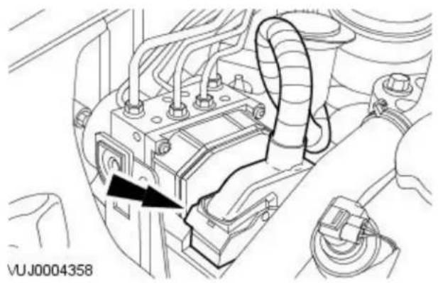
natural_image
Technical line drawing of a vehicle engine compartment with hoses and a black arrow indicating a component (no text or symbols present)- Disconnect the anti-lock brake system (ABS) module electrical connector.

natural_image
Technical diagram of a vehicle's internal components with an inset showing a close-up view of a mechanical component (no text or symbols present)- Detach the hydraulic control unit (HCU).

natural_image
Technical diagram of an automotive engine compartment with directional arrows indicating movement or force (no text or symbols present)- Remove the ABS module.
Installation

- NOTE: Install new retaining bolts.
To install, reverse the removal procedure.
- Tighten to 3 Nm.
- Reprogram the ABS module, using the Jaguar approved diagnostic system.
Anti-Lock Control - Stability Assist - Front Wheel Speed Sensor
Removal and Installation
Removal
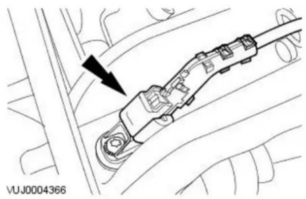
natural_image
Technical diagram of a mechanical assembly with no visible text or symbols- Remove the wheel and tire assembly. For additional information, refer to Section 204-04 Wheels and Tires.
- Disconnect the front wheel speed sensor electrical connector.

natural_image
Top-down diagram of a car interior showing a vehicle with a directional arrow, no text or symbols present- Remove the front wheel speed sensor.
Installation

natural_image
Top-down diagram of a car's side mirror and dashboard, showing a black arrow pointing to the dashboard (no text or symbols present)-
To install, reverse the removal procedure.
-
Tighten to 5 Nm
Anti-Lock Control - Stability Assist - Hydraulic Control Unit (HCU) VIN Range: C00001->J12991
Removal and Installation
Removal
All vehicles
- Disconnect the battery ground cable. For additional information, refer to: Battery Disconnect and Connect (414-01 Battery, Mounting and Cables, General Procedures).
- Raise and support the vehicle. For additional information, refer to: Lifting (100-02 Jacking and Lifting, Description and Operation).
-
Connect a bleed pipe bottle to the caliper bleed nipple and loosen the bleed nipple.
-
Install pedal hold-down tool.
• Install the tool between the pedal and the seat frame.
- Turn the tool hand-wheel to depress and hold the pedal 60 mm (2.4 in) from the 'OFF' position
- This will prevent loss of fluid from the reservoir through disconnected brake pipes.
- Remove the bleed pipe and bottle.
• Tighten the caliper bleed nipple.
- Disconnect and remove the bleed pipe and bottle.
• Install the bleed nipple dust cap.
- Disconnect the hydraulic control unit electrical connector.

natural_image
Technical line drawing of a mechanical component with no visible text or symbolsVehicles with stability assist
- Disconnect the pressure sensor electrical connector.

natural_image
Technical line drawing of a mechanical assembly with no visible text or symbolsAll vehicles

- CAUTION: If brake fluid is spilt on the paintwork, the effected area must be immediately washed down with cold water. Disconnect the hydraulic control unit brake tubes.

natural_image
Technical diagram of a vehicle battery panel with mounting holes and wiring, showing internal components and a close-up inset (no text or symbols)- Remove the hydraulic control unit.
Installation

- To install, reverse the removal procedure.
- Tighten to 17 Nm.
- Bleed the brake system. For additional information, refer to: Brake System Bleeding (206-00 Brake System - General Information, General Procedures).
Anti-Lock Control - Stability Assist - Hydraulic Control Unit (HCU) VIN Range: J12992-> V99999
Removal and Installation
| Special Tool(s) | |
| JDS9013 | Brake pedal hold-down tool JDS 9013 |
Removal
- Disconnect the battery ground cable. For additional information, refer to: Battery Disconnect and Connect (414-01 Battery, Mounting and Cables, General Procedures).
- Raise and support the vehicle. For additional information, refer to: Lifting (100-02 Jacking and Lifting, Description and Operation).
- Connect a bleed pipe bottle to the caliper bleed nipple and loosen the bleed nipple.
- Install pedal hold-down tool.
• Install the tool between the pedal and the seat frame.
- Turn the tool hand-wheel to depress and hold the pedal 60 mm (2.4 in) from the 'OFF' position.
- This will prevent loss of fluid from the reservoir through disconnected brake pipes.
- Remove the bleed pipe and bottle.
• Tighten the caliper bleed nipple.
- Disconnect and remove the bleed pipe and bottle.
• Install the bleed nipple dust cap.
- Disconnect the hydraulic control unit (HCU) electrical connector.

natural_image
Technical diagram of an automotive engine compartment with hoses and a black arrow pointing to a component (no text or symbols present)
natural_image
Technical diagram of a mechanical assembly with multiple curved components and directional arrows indicating flow or movement (no text or symbols present)- WARNING: Brake fluid contains polyglycol ethers and polyglycols. Avoid contact with the eyes. Wash hands thoroughly after handling, as prolonged contact may cause irritation and dermatitis. If brake fluid contacts the eyes, flush the eyes with cold water or eyewash solution and seek medical attention. If taken internally do not induce vomiting, seek immediate medical attention. Failure to follow these instructions may result in personal injury.
- CAUTIONS:
If brake fluid is spilt on the paintwork, the effected area must be immediately washed down with cold water.
Cap the exposed brake tubes and ports to prevent loss of fluid and dirt ingress. Failure to follow this instruction may result in damage to the vehicle.
Disconnect the HCU brake tubes.

natural_image
Technical diagram of a mechanical assembly with no visible text or symbols- Remove the HCU.
Installation
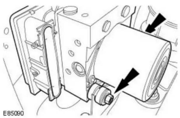
natural_image
Technical diagram of a mechanical assembly with no visible text or symbols- To install, reverse the removal procedure.
- Tighten to 8 Nm.
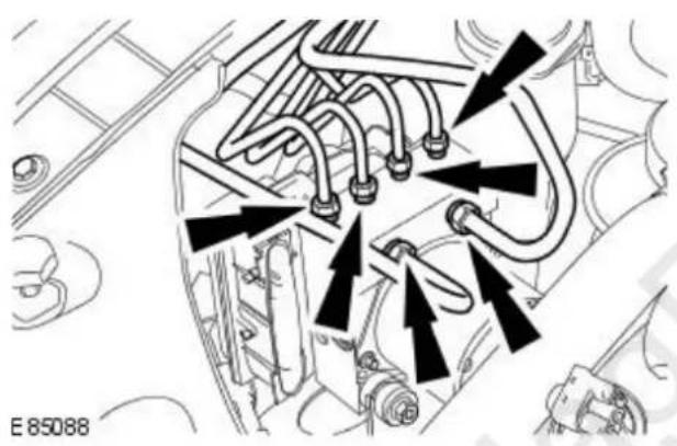
natural_image
Technical diagram of a mechanical component with multiple curved pipes and arrows indicating assembly or connection points (no text or symbols present)- CAUTION: Make sure the brake tubes are installed to the correct ports. Failure to follow this instruction may result in damage to the vehicle.
Tighten to 16 Nm.
- Bleed the anti-lock brake system (ABS). For additional information, refer to: Brake System Bleeding (206-00 Brake System - General Information, General Procedures).
Anti-Lock Control - Stability Assist - Rear Wheel Speed Sensor
Removal and Installation
Removal
Vehicles with 2.5L or 3.0L engine

natural_image
Technical line drawing of a car interior showing engine compartment and wiring (no text or symbols)- Remove the rear seat cushion. For additional information, refer to: Rear Seat Cushion (501-10 Seating, Disassembly and Assembly).
-
Disconnect the rear ABS wheel speed sensor electrical connector.
-
Detach the grommet.
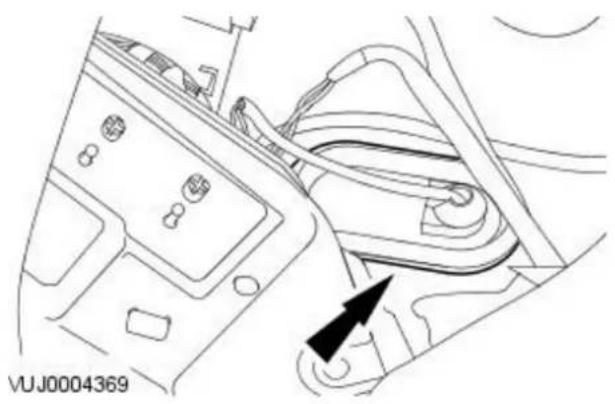
natural_image
Line drawing of a car interior showing dashboard, air intake, and exhaust system (no text or symbols)- Raise and support the vehicle. For additional information, refer to: Lifting (100-02 Jacking and Lifting, Description and Operation).
- Detach the ABS wheel speed sensor wiring harness.
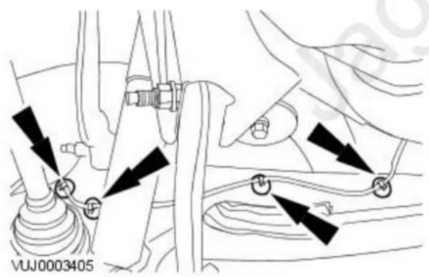
natural_image
Technical diagram showing mechanical components with directional arrows indicating movement or force (no text or symbols present)- Remove the ABS wheel speed sensor.

natural_image
Mechanical assembly diagram showing a lever mechanism with a black arrow pointing to a component (no text or symbols present)
natural_image
Mechanical assembly diagram showing a valve inserted into a car wheel (no text or symbols)- Disconnect the ABS wheel speed sensor electrical connector.

natural_image
Mechanical component diagram showing a central connector with two black arrows pointing to it, no text or symbols present.- Remove the ABS wheel speed sensor.
Installation
Vehicles with 2.5L or 3.0L engine
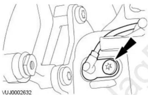
natural_image
Technical line drawing of a mechanical component with a highlighted section and arrow indicator (no text or symbols)-
To install, reverse the removal procedure.
-
Tighten to 22 Nm.
Vehicles with 2.0L or diesel engine
-
To install reverse the removal procedure.
-
Tighten to 7 Nm.
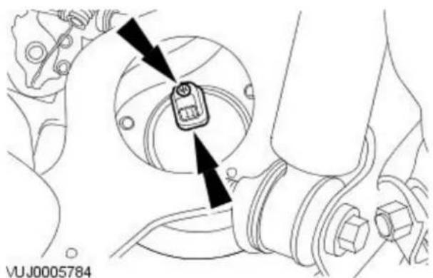
natural_image
Mechanical assembly diagram showing a component with arrows pointing to a central device (no text or symbols present)Anti-Lock Control - Stability Assist - Stability Assist Module
Removal and Installation
Removal

natural_image
Technical line drawing of a vehicle engine compartment with no visible text or symbols- NOTE: Stability assist module is an integral component of the ABS module and cannot be separated.
Disconnect the anti-lock brake system (ABS) module electrical connector.

natural_image
Technical diagram of a vehicle's internal components with an inset showing a close-up of a mechanical component (no text or symbols present)- Detach the hydraulic control unit (HCU).

- Remove the ABS module.
Installation

- NOTE: Install new retaining bolts.
To install, reverse the removal procedure.
- Tighten to 3 Nm.
- Reprogram the ABS module, using the Jaguar approved diagnostic system.
Anti-Lock Control - Stability Assist - Steering Wheel Rotation Sensor
Removal and Installation
Removal

natural_image
Technical line drawing of a car electrical connector with cable and wiring (no text or symbols)- Disconnect the steering wheel rotation sensor electrical connector.

- Remove the upper steering column. For additional information, refer to: Steering Column.
- Remove the steering wheel rotation sensor.
Installation

- To install, reverse the removal procedure.
-
Tighten to 1 Nm.
-
Calibrate the steering wheel angle sensor using the Jaguar approved diagnostic system.
Anti-Lock Control - Stability Assist - Yaw Rate Sensor2.0L Duratorq-TDCi/ 2.0L NA V6 - AJV6/ 2.5L NA V6 - AJV6/ 3.0L NA V6 - AJ27
Removal and Installation
Removal

natural_image
Diagram of a car interior showing steering wheel, dashboard, and steering wheel (no text or symbols)- Remove the floor console trim panel.
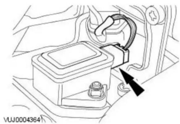
natural_image
Line drawing of a car battery pack with wiring and a directional arrow indicating a component (no text or symbols present)- Disconnect the yaw rate sensor electrical connector.

natural_image
Technical diagram of a vehicle intake bay with arrows pointing to components (no text or symbols)- WARNING: Note the correct orientation of the yaw rate sensor. Remove the yaw rate sensor.
Installation

natural_image
Technical diagram of a vehicle engine compartment with two black arrows pointing to a component (no text or symbols present)- WARNING: Make sure the yaw rate sensor is correctly installed. To install, reverse the removal procedure.
- Tighten to 6 Nm.
Anti-Lock Control - Stability Assist - Yaw Rate Sensor2.2L Duratorq-TDCi (110kW/ 150PS) - Puma
Removal and Installation
Removal
Vehicles with automatic transmission
- Detach the J-gate surround.

natural_image
Diagram of a car interior showing a gear shift lever and directional arrows (no text or symbols)Vehicles with manual transmission
- Detach the gear selector surround.

natural_image
Technical line drawing of a mechanical component with directional arrows indicating motion (no text or symbols)All vehicles
- Detach the ash tray.

natural_image
Technical line drawing of a vehicle rear panel with mounting fixtures and directional arrows indicating movement (no text or symbols)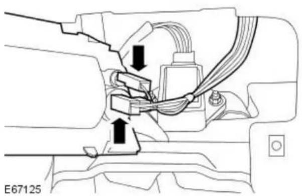
natural_image
Technical diagram of a mechanical assembly with no visible text or symbols- Remove the ash tray.
- Disconnect the electrical connectors.

natural_image
Technical diagram of a mechanical component with two black arrows indicating directional movement or force points (no text or symbols present)
natural_image
Technical line drawing of a mechanical component with wiring and a black arrow indicating a connection point (no text or symbols)- CAUTION: Make sure the yaw rate sensor is not subjected to any form of impact and is not dropped or damaged. Failure to follow this instruction may result in failure of the sensor.
Detach the yaw rate sensor.
- Remove the retaining nuts.
- Remove the yaw rate sensor.
- Disconnect the electrical connector.
Installation

natural_image
Technical line drawing of a mechanical component with two black arrows indicating directional or force points (no text or symbols present)- CAUTION: Make sure the yaw rate sensor is not subjected to any form of impact and is not dropped or damaged. Failure to follow this instruction may result in failure of the sensor.
To install, reverse the removal procedure.
- Tighten to 6 Nm.
Steering System - General Information -
Steering Linkage Specifications
| Steering Linkage Free Play Measurement (mm) Measurement (in) | ||
| Free play (measured at the steering wheel rim) 0-6 0-0.24 | ||
Power Steering Pump Specifications
| Item Specification | |
| Power steering pump relief pressure 106-114 bar |
Lubricants, Fluids, Sealers and Adhesives
| Item Specification | |
| Power steering fluid Dexron 3 |
Steering System - General Information - Steering System
Description and Operation
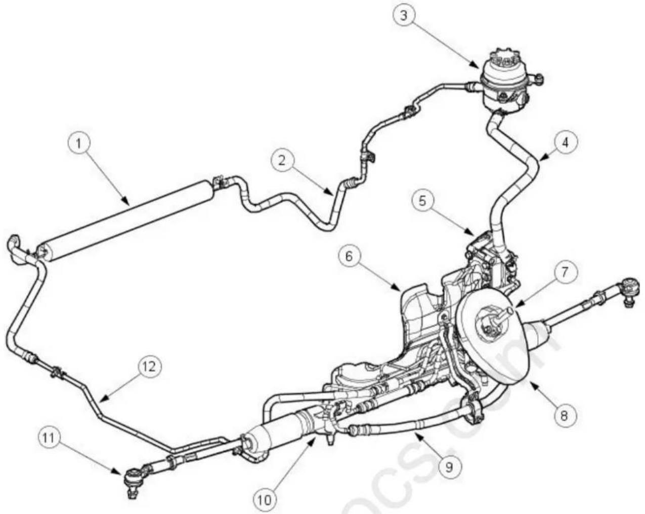
VUJ0003736
| Item Part Number Description | |
| 1 — Fluid cooler | |
| 2 — Low pressure pipe - fluid cooler to reservoir | |
| 3 — Fluid reservoir | |
| 4 — Power steering pump | |
| 5 — Heat shield | |
| 6 — Extension shaft | |
| 7 — Dash panel seal | |
| 8 — High pressure pipe | |
| 9 — Steering gear | |
| 10 — Tie-rod end | |
| 11 — Low pressure pipe - steering gear to fluid cooler | |
Vehicles with 2.0L or diesel engines
The power steering system is a rack and pinion design, with an engine-driven pump providing the steering assistance.
Vehicles with 2.5L or 3.0L engines
The power steering system is a rack and pinion design, with an engine-driven pump providing the steering assistance. The system features variable steering assistance with vehicle speed and a variable ratio steering rack.
Absolute cleanliness must be observed when replenishing the fluid or dismantling any part of the system. New fluid from a sealed container must be used.
- NOTE: If the steering gear, pump or cooler are being replaced for leakage or noise related issues and there is no evidence of fluid contamination, there is no need to replace the reservoir.
In some cases where the fluid clearly contains particulate matter, and the system continues to function, flush the system with fresh fluid and replace the reservoir, as there is the possibility that the reservoir internal filter may be damaged or faulty.
Steering System - General Information - Steering System
Diagnosis and Testing
Inspection and Verification
- Verify the customer concern by driving the vehicle.1.
- Visually inspect for obvious signs of mechanical or electrical damage.2.
Mechanical Inspection Chart
Mechanical Checks
| Incorrect tire pressure, loose wheel nuts, incorrect wheel alignmentLoose tie-rodsLoose damper and spring assemblies or ball jointLoose steering column shaft universal jointsLoose pinch bolts on steering column shaftLoose steering gear assemblyCheck for external damage to the steering gear.- Damaged tie-rodsCAUTION: If a steering gear assembly is returned under warranty with leaking seals, but there is also damage to the steering gear boot/boots the steering gear warranty will be invalid. This is due to the steering gear seals being damaged due to foreign materials entering the steering gear boot and damaging the steering gear seals thereafter.Damaged steering gear bootDamaged accessory drive beltBinding or misaligned steering column, pump or steering gearIncorrect fluid levelHose leaks or line restrictionsHose fouling bodywork |
Electrical Inspection Chart
Electrical Checks/ Tests
| Make sure all connectors are in place (steering gear Servotronic solenoid and steering control module (SCM) - if applicable) |
| Make sure all the fuses are in place and not blown |
| DISCONNECT the steering gear transducer and the steering should become heavy |
| TEST electrical values:- Power Supply to the SCM = 12 Volts- Steering gear transducer resistance 7.0 to 7.5 Ohms is normal (limits: less than 5 Ohms and greater than 9 Ohms would be declared unacceptable)- Steering gear transducer voltage = 6 Volts- Steering gear transducer current = 840 mA at 0 mph reducing to 0 mA at maximum speed |
| RECONNECT all electrical items disturbed during testing |
-
- If an obvious cause for an observed or reported concern is found, correct the cause (if possible) before proceeding to the next step.
-
- Check the power steering fluid condition. For additional information, REFER to Power Steering Fluid Condition Check in this section.
-
- If the concern is not visually evident, verify the symptom and REFER to Steering Fault Diagnosis by Symptom Charts in this section.
Steering Relay Harness Connector

flowchart
graph TD
    1 --> 2
    2 --> 3
    3 --> 4
    4 --> 5
    5 --> 6
    6 --> 1
E39815
| Item Description | |
| 1 Steering transducer ground | |
| 2 Ignition feed | |
| 3 Steering transducer feed | |
| 4 Ground | |
| 5 Speed sensor signal | |
| 6 Serial interface | |
Steering Linkage Inspection and Backlash (Freeplay) Check

CAUTION: Steering gear boots must be handled carefully to avoid damage. Use new clamps when installing steering gear boots.
Inspect the boots for cuts, deterioration, twisting or distortion. Check the steering gear boots to make sure they are tight. Install new boots or clamps as necessary.
- NOTE: The following steps must be carried out with assistance.
-
- With the wheels in the straight ahead position, gently turn the steering wheel to the left and the right to check for free play.
-
- Free play should be between 0 and 6 mm (0 and 0.24 in) at the steering wheel rim. If the free play exceeds this limit, either the ball joints are worn, the lower steering column joints are worn or the backlash of the steering gear is excessive.

CAUTION: DO NOT attempt to adjust the steering gear yoke. Failure to follow this instruction will result in the steering gear warranty come invalid.
-
- The backlash of the steering gear cannot be adjusted, install a new steering gear. For additional information, REFER to Section 211-02 Power Steering.
-
- Grasp the steering wheel firmly and move it up and down and to the left and right without turning the wheel to check for column bearing wear, steering wheel or steering column. For additional information, REFER to Section 211-04 Steering Column.
Power Steering Fluid Condition Check
- Run the engine for 2 minutes.1.
-
Check the power steering fluid system level.2.
-
- Observe the color and the odor. The color under normal circumstances should be dark reddish, not brown or black.
-
Allow the fluid to drip onto a facial tissue and examine the stain.4.
-
- If evidence of solid material is found, the power steering fluid system should be drained for further inspection.
-
- If fluid contamination or steering component failure is confirmed by the sediment in the power steering fluid system, REFER to Steering Fault Diagnosis by Symptom Charts in this section.
Power Steering Pressure Test
Test Equipment

| Item Special Tool Number Description | |
| 1 211-011 Pressure Gauge Hose | |
| 2 211-011-08 Pump Return Hose | |
| 3 211-011-07 Pump Return Hose Connector | |
| 4 211-011-03/2 Test Equipment to High Pressure Hose Adaptor | |
| 5 211-011-03/1 Pump High Pressure Outlet to Hose Adaptor | |
| 6 211-011-02 Pump Adaptor to Control Valve Hose | |
| 7 211-011-01 Control Valve | |
| 8 211-011 Pressure Gauge | |
| 9 - 'O' Ring Seal |
The measurement of the maximum system pressure, (which is governed by the pressure relief valve) is achieved by inserting the Service Tool (pressure gauge and adaptors) into the fluid circuit of the power steering system. Run the engine at idle speed, turn the steering from lock to lock and read the maximum pressure recorded on the gauge.
Installing Test Equipment
To install the pressure test equipment:
- Place a suitable drain tray below the power steering pump.
• Install a hose clamp on the reservoir to pump hose prior to disconnecting any hoses, to avoid unnecessary loss of fluid. - Disconnect the hose from the power steering pump high pressure outlet.
• Install the pump outlet to hose adaptor (5). Do not omit the 'O' ring seal (9). - Connect the power steering pump adaptor to control valve hose (6) of the test equipment.
• Install the adaptor (4) in the high pressure hose previously removed from the power steering pump outlet. - Connect the connector (3) of the test equipment hose (2) to the adaptor (4).
- Remove the hose clamp from the reservoir hose.
- Start the engine.
With the control valve (7) OPEN and the engine idling, the following system pressures may be checked:
- During turning.
- When the steering is held on full lock.
- With the steering at rest.
• CAUTIONS:

To avoid excessive heating of the power steering pump, do not close the valve for longer than 5 seconds maximum.

Do not drive the vehicle with the test equipment installed.
With the control valve (7) CLOSED the power steering pump maximum output pressure can be checked.
Removing Test Equipment
To remove the test equipment:
• Install a hose clamp on the reservoir to power steering pump hose.
- Removing the test equipment is a reversal of the installation instructions.
• Install a new 'O' ring seal (9) to the power steering pump high pressure outlet to hose connection.
• Install the original hose to the power steering pump.
- Remove the clamp from the reservoir to the power steering pump hose.
- Top-up the reservoir fluid.
- Bleed the power steering system. For additional information,
REFER to Power Steering System Bleeding - in this section.
Steering Fault Diagnosis by Symptom Charts
Leakage
| Condition Possible Sources Action | ||
| Fluid leakage | Confirm the position of the fluid leak. | CLEAN the area of the leak.Inspect the area and confirm the exact position of leak.Make sure the fluid is not from another system on the vehicle. |
| Overfilled system. | CORRECT the fluid level as necessary. | |
| Component leak. | NOTE: Record the position of the leak and some indication of the rate of the leak on the Warranty Return Record Sheet.LOCATE the suspect component or CHECK hose connections and repair as necessary. | |
| Damaged fluid cap. INSTALL a new fluid cap. | ||
| Loose or damaged hose fittings. | TIGHTEN or INSTALL a new hose as necessary. | |
| Leakage at power steering pump. | INSTALL a new power steering pump as necessary. For additional information,REFER to Section 211-02 Power Steering. | |
| Fluid leakage | Leakage at steering hose to steering gear connection. | CHECK steering hose to steering gear connection for leakage. CHECK and TIGHTEN the steering hose to steering gear connection retaining bolts/bolts as necessary. |
| Power steering fluid leakage at O-ring seals. | CHECK the power steering system for signs of steering fluid loss from O-ring seals.INSTALL new O-ring seals as necessary.BLEED the power steering system. For additional information,REFER to Section 211-00 Steering System - General Information. | |
| Power steering fluid leakage from transfer pipes. | CHECK the power steering system for signs of steering fluid loss from the transfer pipes.CHECK and TIGHTEN the transfer pipes if required, INSTALL new transfer pipes as necessary.BLEED the power steering system. For additional information,REFER to Section 211-00 Steering System - General Information. | |
| Power steering fluid leakage from the steering gear. | CHECK the power steering gear for signs of fluid loss.INSTALL a new steering gear as necessary. For additional information,REFER to Section 211-02 Power Steering. | |
| Power steering fluid leakage from steering gear boot. | CHECK the power steering gear for signs of fluid loss.INSTALL a new steering gear as necessary. For additional information,REFER to Section 211-02 Power Steering. | |
Functional
| Condition Possible Sources Action | ||
| Free play at steering wheel | Excess play in the steering linkage. | CHECK the steering linkage for excess play. For additional information,REFER to the Steering Linkage Inspection and Backlash (Freeplay) Check in this section. |
| Steering wheel loose. | CHECK and TIGHTEN the steering wheel retaining bolt/bolts as necessary. For additional information,REFER to Section211-04 Steering Column. | |
| Lower steering column pinch bolt loose. | CHECK and TIGHTEN the lower steering column pinch bolts as necessary. For additional information,REFER to Section211-04 Steering Column. | |
| Excessive wear in lower steering column. | CHECK for lower steering column for wear in the universal joints. If wear is present,INSTALL a new lower steering column as necessary. | |
| Wear in suspension joints. | CAUTION: DO NOT attempt to adjust the steering gear yoke. Failure to follow this instruction will result in the steering gear warranty to become invalid.CHECK for excess wear in the front suspension joints. For additional information,REFER to Section204-00 Suspension System - General Information. | |
| Vehicle wanders from side to side on the road, when the vehicle is driven straight ahead and the steering wheel is held in a firm position | Incorrect tire pressure or tire size. | CHECK and ADJUST the tire pressure. For additional information,REFER to Section204-04 Wheels and Tires.INSTALL a new tire as necessary. For additional information,REFER to Section204-04 Wheels and Tires. |
| Vehicle is unevenly or excessively loaded. | ADJUST the load evenly. | |
| Loose/worn tie-rods. | INSTALL a new tie-rod end. For additional information,REFER to Section211-03 Steering Linkage. | |
| Steering gear bolts loose or damaged. | TIGHTEN or INSTALL new bolts. | |
| Loose or worn suspension ball joint(s). | INSTALL a new suspension ball joint assembly. For additional information,REFER to Section204-01 Front Suspension. | |
| Steering column universal joint pinch bolt loose. | TIGHTEN the steering column universal joint pinch bolt. For additional information,REFER to Section211-04 Steering Column. | |
| Incorrect toe adjustment. | ADJUST as necessary. For additional information,REFER to Section204-00 Suspension System - General Information. | |
| Loose or worn rear suspension. | TIGHTEN loose, or INSTALL new rear suspension components. For additional information,REFER to Section 204-02 Rear Suspension. | |
| Vehicle tends to pull to one side when driven on a level surface | Incorrect tire pressure.Incorrect tire size or different tire/tread typeUneven tire wear | CHECK and ADJUST the tire pressure. For additional information,REFER to Section 204-04 Wheels and Tires.INSTALL a new tire as necessary. For additional information,REFER to Section 204-04 Wheels and Tires. |
| Vehicle is unevenly loaded or overloaded. | Adjust the load. | |
| Incorrect toe adjustment. | ADJUST as necessary. For additional information,REFER to Section 204-00 Suspension System - General Information. | |
| Damaged front suspension components. | INSTALL new front suspension components as necessary. For additional information,REFER to Section 204-01 Front Suspension. | |
| Damaged rear suspension components. | INSTALL new rear suspension components as necessary. For additional information,REFER to Section 204-02 Rear Suspension. | |
| Steering gear valve effort out of balance. | SHIFT the transmission into NEUTRAL while driving at no more than 30 miles/hour (50 km/h) and turn the ignition to position I (engine OFF-coasting). If the vehicle does not pull with the engine off, INSTALL a new steering gear. For additional information,REFER to Section 211-02 Power Steering.If the vehicle does drift with the engine off, CROSS SWITCH front wheel assemblies.If the vehicle pulls to the opposite side, SWITCH wheels that were on the rear to the same side on the front.If the vehicle pull direction is not changed, CHECK the front suspension components and toe adjustments. For additional information,REFER to Section 204-01 Front Suspension. | |
| Check the front and rear brakes for correct operation. | ADJUST as necessary. For additional information,REFER to Section 206-00 Brake System - General Information. | |
| Check for bent rear suspension components and for damaged coil springs in the front suspension. | INSTALL new rear suspension components as necessary. For additional information,REFER to Section 204-02 Rear Suspension.INSTALL new front suspension components as necessary. For additional information,REFER to Section 204-01 Front Suspension. | |
| Check the rear suspension for loose or worn suspension components. | TIGHTEN or INSTALL new components as necessary. For additional information,REFER to Section 204-02 Rear Suspension. | |
| Incorrect underbody alignment. | CHECK underbody alignment. For additional information,REFER to Section 502-00 Uni-Body, Subframe and Mounting System. | |
| Poor returnability of the steering | Lower steering column interference. | CHECK the steering column is free from interference from the engine harness, sound proofing or the floor covering. |
| Incorrect tire pressure. | CHECK and ADJUST the tire pressure. For additional information,REFER to Section 204-04 Wheels and Tires. | |
| Incorrect tire size or type. | INSTALL a new tire as necessary. For additional information,REFER to Section 204-04 Wheels and Tires. | |
| Steering column upper shroud fouling on the steering wheel. | CHECK steering column upper shroud for fouling. ADJUST as necessary. | |
| Steering column universal joints binding. | INSTALL a new steering column. For additional information,REFER to Section 211-04 Steering Column. | |
| Steering column shaft floor seal binding. | CHECK the steering column shaft floor seal for correct fitment and REFIT as necessary. | |
| Steering column shaft floor seal may be torn. | INSTALL a new steering column shaft floor seal as necessary. | |
| Binding or damaged tie-rods. | CHECK tie-rod end for excessive wear or tightness in ball joint. INSTALL a new tie-rod end. For additional information,REFER to Section 211-03 Steering Linkage. | |
| Damaged or worn front suspension components. | INSTALL new front suspension components as necessary. For additional information,REFER to Section204-01 Front Suspension. | |
| Incorrect toe adjustment. | ADJUST as necessary. For additional information,REFER to Section204-00 Suspension System -General Information. | |
| Excessive steering efforts required during low speed manoeuvring and/or during parking manoeuvres | Low power steering fluid. | CHECK steering system for signs of steering fluid loss.BLEED the power steering system. For additional information,REFER to Section211-00 Steering System - General Information. |
| Damaged accessory drive belt tensioner. | INSTALL a new accessory drive belt tensioner. | |
| Hose or cooler line restriction. | CHECK hose or cooler lines for correct routing.INSTALL a new hose as necessary. | |
| Fluid aeration. | BLEED the system. For additional information,REFER toPower Steering System Bleeding in this section. | |
| Steering transducer not closed - no feed voltage. | CHECK the steering transducer circuit. For additional information,REFER to the wiring diagrams.Carry out the electrical checks and tests. For additional information,REFER to the Electrical Checks and Tests in this section. | |
| Steering transducer not closed - cable fault. | CHECK the steering transducer circuit. For additional information,REFER to the wiring diagrams.Carry out the electrical checks and tests. For additional information,REFER to the Electrical Checks and Tests in this section. | |
| Steering control module (SCM) defective. | CHECK the SCM and INSTALL a new SCM as necessary. | |
| Power steering fluid delivery pressure or flow too low. | CHECK the power steering pressure. For additional information,REFER to the Power Steering Pressure Test in this section.INSTALL a new power steering pump as necessary. For additional information,REFER to Section211-02 Power Steering. | |
| Internal steering gear leakage. | CHECK the power steering pressure. For additional information,REFER to the Power Steering Pressure Test in this section.INSTALL a new steering gear as necessary. For additional information,REFER to Section211-02 Power Steering. | |
| Steering operation is very heavy when driving, but when stationary manoeuvring is good | Steering transducer open early. | CHECK steering transducer and INSTALL a new steering transducer as necessary.Carry out the electrical checks and tests. For additional information,REFER to the Electrical Checks and Tests in this section. |
| Steering transducer open early, steering control module (SCM) fault. | CHECK SCM and INSTALL a new SCM as necessary. | |
| Steering transducer open early, speedo signal error. | CHECK speedo circuit. For additional information,REFER to the wiring diagrams. | |
| Steering operation is very light when driving, but when stationary manoeuvring is good | Steering transducer not open,(no power steering fluid flow). | CHECK the power steering fluid condition. For additional information,REFER to the Power Steering Fluid condition check in this section. |
| Steering transducer not open, steering control module (SCM) fault. | CHECK the SCM and INSTALL a new SCM as necessary.Carry out the electrical checks and tests. For additional information,REFER to the Electrical Checks and Tests in this section. | |
| Steering transducer not open, speedo signal error. | CHECK the speedo circuit. For additional information,REFER to the wiring diagrams. | |
| CHECK the power steering fluid low pressure pipe for restricted flow. | INSTALL a new power steering fluid low pressure pipe. | |
| Steering heavy operation during rapid manoeuvring | Air in power steering system.Fluid loss at the power steering pump shaft seal. | CHECK for an air leak into the power steering system and repair as necessary.BLEED the power steering system. For additional information,REFER toPower Steering System Bleeding - in this section.CHECK the power steering pump for signs of steering fluid loss.INSTALL a new power steering pump as necessary. For additional information,REFER to Section 211-02 Power Steering. |
| Power steering fluid delivery pressure or flow too low. | CHECK the power steering pump for signs of steering fluid loss.CHECK the power steering pressure. For additional information,REFER to the Power Steering Pressure Test in this section.INSTALL a new power steering pump as necessary. For additional information,REFER to Section 211-02 Power Steering. | |
| Steering heavy operation in one direction | Lower steering column interference. | CHECK the steering column is free from interference from the engine harness, sound proofing or the floor covering. |
| Incorrect steering geometry. | CHECK the front wheel alignment. For additional information,REFER to Section 204-00 Suspension System - General Information. | |
| Faulty rotary valve/seal. | CHECK the power steering pressure. For additional information,REFER to the Power Steering Pressure Test in this section.INSTALL a new steering gear as necessary. For additional information,REFER to Section 211-02 Power Steering. | |
| Tire fouling on the wheel arch liner. | CHECK for clearance between the tire and the wheel arch liner.Remove and refit the wheel arch liner or INSTALL a new wheel arch liner as necessary. | |
| Steering heavy operation in both directions | Low power steering fluid. | CHECK steering system for signs of steering fluid loss.BLEED the power steering system. For additional information,REFER to Section 211-00 Steering System - General Information. |
| Air in power steering system. | CHECK the power steering pump for signs of steering fluid loss.INSTALL a new power steering pump as necessary. For additional information,REFER to Section 211-02 Power Steering. | |
| Fluid loss at the power steering pump shaft seal. | CHECK the power steering pump for signs of steering fluid loss.INSTALL a new power steering pump as necessary. For additional information,REFER to Section 211-02 Power Steering. | |
| Power steering fluid delivery pressure or flow too low. | CHECK the power steering pump for signs of steering fluid loss.CHECK the power steering pressure. For additional information,REFER to the Power Steering Pressure Test in this section.INSTALL A new power steering pump as necessary. For additional information,REFER to Section 211-02 Power Steering. | |
| Steering operation varies from heavy to light when driving at constant speed | Lower steering column interference. | CHECK the steering column is free from interference from the engine harness, sound proofing or the floor covering. |
| Incorrect speedometer signal. | CHECK the speedo circuit. For additional information, refer to the wiring diagrams. | |
| Steering transducer cable/connection faulty or grounded. | CHECK the steering transducer circuit. For additional information, refer to the wiring diagrams.Carry out the electrical checks and tests. For additional information,REFER to the Electrical Checks and Tests in this section. | |
| Steering wheel varies from light to heavy two times per revolution | Lower steering column interference. | CHECK the steering column is free from interference from the engine harness, sound proofing or the floor covering. |
| Steering column universal joints binding. | INSTALL a new steering column. For additional information,REFER to Section 211-04 Steering Column. | |
| Seized or damaged steering components. | CHECK for wear or failure of suspension bushes and ball joints. For additional information,REFER to Section 204-00 Suspension System - General Information. | |
| Accessory drive belt squeal | Incorrect accessory drive belt tension or accessory drive belt glazed. | CHECK accessory drive belt condition and INSTALL a new accessory drive belt as necessary. For additional information,REFER to Section 303-05 Accessory Drive. |
| Chirp noise in the steering pump | Loose or worn accessory drive belt. | CHECK accessory drive belt condition and INSTALL a new accessory drive belt as necessary. For additional information,REFER to Section 303-05 Accessory Drive. |
| Power steering pump noisy | Low power steering fluid. | CHECK steering system for signs of steering fluid loss.BLEED the power steering system. For additional information,REFER to Section 211-00 Steering System - General Information. |
| Power steering pump worn or otherwise defective. | CHECK for leaks. REPAIR as necessary.CHECK the power steering pressure. For additional information,REFER to the Power Steering Pressure Test in this section.INSTALL a new power steering pump as necessary. For additional information,REFER to Section 211-02 Power Steering. | |
| Whine type noise | Aerated fluid. | BLEED the power steering system. For additional information,REFER to Power Steering System Bleeding - in this section. |
| Power steering pump. | CHECK for leaks. REPAIR as necessary.INSTALL a new power steering pump as necessary. For additional information,REFER to Section 211-02 Power Steering. | |
| Noise during steering gear movement | Low power steering fluid. | CHECK steering system for signs of steering fluid loss.BLEED the power steering system. For additional information,REFER to Section 211-00 Steering System - General Information. |
| Water contamination to the power steering fluid. | DRAIN the power steering system.BLEED the power steering system. For additional information,REFER to Section 211-00 Steering System - General Information. | |
| Cavitation due to restricted power steering feed hose. | CHECK and reposition power steering feed hoses and INSTALL new hoses as necessary. | |
| Continuous noise | Low power steering fluid. | CHECK steering system for signs of steering fluid loss.BLEED the power steering system. For additional information,REFER to Section 211-00 Steering System - General Information. |
| Power steering pump drive loose. | CHECK power steering coupling and power steering pump.INSTALL a new power steering coupling or power steering pump as necessary. For additional information,REFER to Section 211-02 Power Steering. | |
| Incorrect accessory drive belt tension or accessory drive belt glazed. | CHECK accessory drive belt condition and INSTALL a new accessory drive belt as necessary. For additional information,REFER to Section 303-05 Accessory Drive. | |
| Power steering pump drive pulley loose. | CHECK and TIGHTEN the power steering pump drive pulley retaining bolts as necessary. For additional information,REFER to Section 303-03A Engine Cooling / 303-03B Engine Cooling. | |
| Power steering pump retaining bolts loose. | CHECK the power steering pump retaining bolts and TIGHTEN as necessary. | |
| Power steering hose/pipe in contact with the vehicles body. | CHECK and reposition power steering hoses/pipes, INSTALL new hoses/pipes as necessary. | |
| Power steering hose restricted/twisted. | CHECK and reposition power steering hose, replace hose as necessary. | |
Vibration
| Condition Possible Sources Action | ||
| Feedback (knocking noises in the steering gear) - condition where roughness is felt in the steering wheel by the driver when the vehicle is driven over rough surfaces | Loose/worn tie-rods. | INSTALL a new tie-rod end. For additional information,REFER to Section211-03 Steering Linkage. |
| Steering gear retaining bolts loose or damaged. | CAUTION: DO NOT attempt to adjust the steering gear yoke. Failure to follow this instruction will result in the steering gear warranty to become invalid.CHECK and TIGHTEN the steering gear retaining bolts.INSTALL new retaining bolts as necessary. For additional information,REFER to Section211-02 Power Steering. | |
| Loose suspension bushing, bolts or ball joints. | TIGHTEN or INSTALL new components as necessary. For additional information,REFER to Section204-01 Front Suspension. | |
| Steering column retaining bolts loose. | CAUTION: DO NOT attempt to adjust the steering gear yoke. Failure to follow this instruction will result in the steering gear warranty to become invalid. | |
| Condition Possible Sources Action | ||
| CHECK and TIGHTEN the steering column retaining bolts/nuts and pinch bolts if required. For additional information,REFER to Section 211-04 Steering Column. | ||
| Excessive wear in steering column assembly. | CHECK for steering column for wear in the universal joints and bearings. If wear is present, INSTALL a new steering column as necessary. For additional information,REFER to Section 211-04 Steering Column. | |
| Nibble (Shimmy) Oscillation of the steering wheel (not vertical which is SHAKE). This is driven by road wheel imbalance. | Road wheel imbalance. | CHECK for road wheel imbalance.CHECK for relevant SERVICE BULLETINS/SERVICE ACTIONS for the vehicle on Jaguar Communications Online (JCOL) or in hard copy form. |
| Steering wheel replacement. | CHECK for relevant SERVICE BULLETINS/SERVICE ACTIONS for the vehicle on Jaguar Communications Online (JCOL) or in hard copy form. | |
| Rack replacement. | CHECK for relevant SERVICE BULLETINS/SERVICE ACTIONS for the vehicle on Jaguar Communications Online (JCOL) or in hard copy form. | |
Description of General Steering System Noises
Boom
Rhythmic sound like a drum roll or distant thunder. May cause pressure on the ear drum.
Buzz
Low-pitched sound, like a bee. Usually associated with vibrations.
Chatter
Rapidly repeating metallic sound.
Chuckle
Rapid noise that sounds like a stick against the spokes of a spinning bicycle wheel.
Chirp
High pitched rapidly repeating sound, like chirping birds.
Click
Light sound, like a ball point pen being clicked.
Click/ Thump
Heavy metal-to-metal sound, like a hammer striking steel.
Grind
Abrasive sound, like a grinding wheel or sandpaper rubbing against wood.
Groan/ Moan
Continuous, low-pitched humming sound.
Groan/ Howl
Low, guttural sound, like an angry dog.
Hiss
Continuous sound like air escaping from a tire valve.
Hum
Continuous sound of varying frequencies, like a wire humming in the wind.
Knock
Heavy, loud repeating sound like a knock on a door.
Ping
Similar to knock, except at higher frequency.
Rattle
A sound suggesting looseness, such as marbles rolling around in a can.
Roar
Deep, long, prolonged sound like an animal, or winds and ocean waves.
Rumble
Low, heavy continuous sound like that made by wagons or thunder.
Scrape
Grating noise like one hard plastic rubbing part rubbing against another.
Squeak
High-pitched sound like rubbing a clean window.
Squeal
Continuous, high-pitched sound like running finger nails across a chalkboard.
Tap
Light, hammering sound like tapping pencil on edge of table. May be rhythmic or intermittent.
Weep
Continuous mid-range sound (lower frequency than squeal, higher frequency than groan).
Whir/ Whine
High-pitched buzzing sound, like an electric motor or drill.
Whistle
Sharp, shrill sound, like wind passing a small opening.
Description of Specific Steering System Noise Types
Belt Squeal
Belt squeal is a high frequency air-borne noise generated by slippage of the ribbed Vee belt on the power steering pump pulley. Squeal increases with system loading and at the end of lock.
Clonk
Clonk is a structure-borne noise heard as a loose-sounding rattle or vibration coming from the steering column. Clonk can be identified by driving and turning over cobblestones, rough roads, or high frequency bumps such as 25-50 mm tall tar strips. Clonk requires a tie-rod load impact.
Column Knock
Column knock is a loose-sounding rattle or vibration generated by the steering column shaft contacting other portions of the column assembly. The noise is both audible and tactile. Column knock is generated by driving over cobblestones or rough pavement. It is not necessary to turn the steering wheel to create this noise.
Column Rattle
Column rattle is a metallic sounding noise created when applying a highly impulsive force to the steering wheel. Column rattle is often used to combine the more general group of column noises including clonk and column knock. Column rattle noises can be caused by clonk, knock, loose column components, bonus parts etc. A series of parked, straight-line driving, and cornering test should be carried out to isolate the source/sources.
Grinding/ Scrape
Grinding is a low frequency noise in the column when the steering wheel is turned. Is generally caused by interference between moving components such as the steering wheel to steering column shroud.
Grunt (Squawk)
Grunt is a "honking" sound elicited when coming off one of the steering stops. Grunt is generally excited during parking manoeuvres with a low to medium speed steering input.
Hiss (Swish)
Hiss or Valve Hiss is a high-frequency sound coming from the steering gear when the system is loaded. It is a rushing or "swish" noise that doesn't change frequency with RPM. Hiss is the general noise generated by the flow of hydraulic fluid through restrictions in the steering system. Restrictions include the rotary steering valve, power steering tubes, connectors, tuning orifices, etc. Hiss can be air-borne and structure-borne, but the structure-borne path through the steering intermediate shaft is usually dominant.
Moan (Groan)
Moan is the general structure-borne noise of the steering system. Moan is primarily transmitted to the driver via the body structure through the pump mount, engine mounts, power steering lines and power steering brackets. On some vehicles, moan is a load humming noise, often present when the wheel is turned and the system is loaded. It may change frequency with engine RPM and if the system is loaded or unloaded.
Rack Knock (Rack Slap)

CAUTION: DO NOT attempt to adjust the steering gear yoke. Failure to follow this instruction will result in the steering gear warranty come invalid.
Rack Knock is a rattle sound and steering wheel vibration caused by separation of the steering gear and pinion while driving over bumps. It
is a structure-borne noise transmitted through the intermediate shaft and column. Rack knock can also be heard as a "thump" or impact noise that occurs with the vehicle stationary when the steering wheel is released from a loaded position and allowed to return to rest. Noise occurs with the engine on or off.
Rattles
Rattles are noises caused by knocking or hitting with components in the steering system. Steering rattles can occur in the engine compartment, the suspension, or the passenger compartment. Rattles can be caused by loose parts, movable and flexible parts, and improper clearances.
Squeaks/ Scrapes
Squeaks/Scrapes are noises due to friction or component rubbing anywhere in the steering system. Squeaks/Scrapes have appeared in steering linkages and joints, in column components and in column and steering wheel trim parts.
Weep
Weep is an air-borne noise, occasionally generated when turning the steering across lock at a constant rate. When present on a vehicle the noise, once initiated can often be maintained across a large proportion of the available steering movement.
Whistle
Whistle is similar to hiss but is louder and of a higher frequency. It is also more of a pure tone noise than hiss. Whistle is air-borne and is generated by a high flow rate of hydraulic fluid through a small restriction.
Zip
Zip noise is the air-borne noise generated by power steering pump cavitation when power steering fluid does not flow freely through the suction hose from the reservoir to the pump. Zip primarily occurs during cold weather at start-up.
Steering System Vibrations and Harshness
Buzz
Buzz is a tactile rotary vibration felt in the steering wheel for slow steering inputs. Buzz can also be called a grinding feel and it is closely related to grunt and is caused by high system gain with low damping. Buzz is generally excited during parking manoeuvres with low to medium speed steering input.
Buzz (Electrical)
A different steering buzz can be caused by pulse width modulated (PWM) electric actuators used in variable assist steering systems. This buzz is felt by turning the ignition key to run without starting the engine and holding onto the steering wheel. In extreme cases, the buzz can be felt with the engine running also.
Column/ Steering Wheel Shake
Column shake is a low frequency vertical vibration excited by primary engine vibrations.
Nibble (Shimmy)
Steering nibble is a rotary oscillation or vibration of the steering wheel, which can be excited at a specific vehicle speed. Nibble is driven by wheel and tire imbalance exciting a suspension recession mode, which then translates into steering gear travel and finally steering wheel nibble.
Shudder (Judder)
Shudder is a low frequency oscillation of the entire steering system (tire, wheels, steering gear and linkage, etc.) when the vehicle is steered during static-park or at low speeds. Shudder is very dependent on road surface.
Torque Ripple
Torque ripple is a concern with Electric Power Steering (EPS) systems. Torque ripple is most evident at static-park steering the wheel very slowly from lock to lock. Torque ripple is primarily caused by motor commutation.
Torque/ Velocity Variation (Phasing/ Effort Cycling)
Steering wheel torque variation occurring twice in one revolution is normally as a result of problems with the lower steering column (intermediate shaft), but foul conditions generally result in either constant stiffness or single point stiffness. Depending upon the orientation of the joints, the steering can feel asymmetric (torque falling off in one direction and rising in the other) or else it can simply have pronounced peaks and troughs as the steering moves from lock to lock.
Wheel Fight (Kick Back)
Wheel fight is excess feedback of sudden road forces through the steering system and back to the driver. It is evaluated at all vehicle speeds over cobblestones, rough roads, and potholes. The tires, wheels, and suspension generate forces into the steering systems. Steering friction, hydraulic damping, hydraulic compliance, mechanical compliance, steering ratio, and assist gain all affect how much is transmitted to the driver.
Steering Linkage

CAUTION: Steering gear boots must be handled carefully to avoid damage. Use new clamps when installing steering gear boots.
Inspect the boots for cuts, deterioration, twisting or distortion. Check the steering gear boots to make sure they are tight. Install new boots or clamps as necessary.
- NOTE: The following steps must be carried out with assistance.
- With the wheels in the straight ahead position, gently turn the steering wheel to the left and the right to check for free play.
-
- Free play should be between 0 and 6 mm (0 and 0.24 in) at the steering wheel rim. If the free play exceeds this limit, either the
-
⚠️ CAUTION: DO NOT attempt to adjust the steering gear yoke. Failure to follow this instruction will result in the steering gear warranty to become invalid.
-
The backlash of the steering gear cannot be adjusted, install a new steering gear. For additional information, REFER to Section 211-02 Power Steering.
-
Grasp the steering wheel firmly and move it up and down and to the left and right without turning the wheel to check for column bearing wear, steering wheel or steering column. For additional information, REFER to Section 211-04 Steering Column.
Steering System - General Information - Power Steering System Filling
General Procedures

natural_image
Mechanical assembly diagram showing a valve inserted into a housing component with a black arrow indicating direction (no text or symbols present)- NOTE: When filling the reservoir, make sure that the fluid is clean and not agitated prior to use. The fluid should be poured slowly into the reservoir to minimize the possibility of aeration.
Fill the reservoir.
- NOTE: Do not start the engine.
Turn the steering from lock to lock.
- Check the fluid level. Fill the reservoir if necessary.
- Start the engine and allow to idle. Top up the reservoir as air is vented.
- With the engine idling turn the steering from lock to lock topping up the reservoir if necessary.
- When no further change of fluid level occurs run engine for a further 20 minutes to vent any remaining air.
- With the engine idling, turn the steering wheel from lock to lock. If excessive noise is apparent or shudder is evident through the steering wheel, repeat the filling procedure.
Steering System - General Information - Power Steering System Flushing
General Procedures
- NOTE: If heavy steering or contamination within the power steering system is found, it is necessary to carry out the system flush procedure as detailed below. If any components have been replaced in the power steering system the procedure below must be carried out in full.
- NOTE: Some variation in the illustrations may occur, but the essential information is always correct.

natural_image
Technical diagram of a mechanical component with arrows indicating assembly or flow direction (no text or symbols present)- Remove the power steering fluid reservoir cap.
-
Using a suitable syringe, remove the power steering fluid from the power steering fluid reservoir.
-
CAUTION: Be prepared to collect escaping fluids.
- NOTE: Note the orientation of the clip.
Detach the power steering fluid reservoir.
- Detach but do not remove the power steering fluid reservoir.
- Release the power steering fluid return hose from the power steering fluid reservoir.
- If a quick release coupling is fitted to the power steering return hose, release the power steering fluid return hose from the coupling by removing the clip.

natural_image
Technical line drawing of a mechanical component with blue and black parts, no visible text or symbols- CAUTION: Be prepared to collect escaping fluids.
- NOTE: Make sure that all openings are sealed. Use new blanking caps.
Using a suitable blanking cap, cap the power steering reservoir return pipe.

natural_image
Side profile illustration of a car with a blue lock attached, showing the hood and side panel (no text or symbols)- CAUTION: Be prepared to collect escaping fluids.
- NOTE: Make sure the extended pipe is not kinked or twisted and is correctly secured with hose clips.
Attach a suitable pipe to the power steering return hose to allow the fluid to drain.
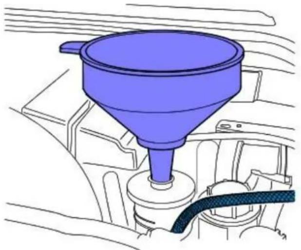
natural_image
Illustration of a blue funnel mounted on a vehicle engine compartment, with no visible text or symbols.E94372
- NOTE: The suitable funnel should have the a capacity of 4 litres and O-ring seal
- NOTE: The suitable funnel must be tightly sealed to the power steering fluid reservoir to avoid fluid leakage.
Install a suitable funnel onto the power steering fluid reservoir.
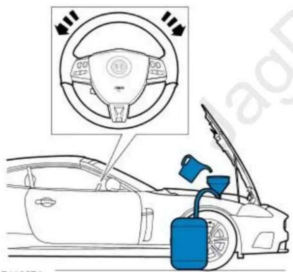
E119674
- WARNING: Do not work on or under a vehicle supported only by a jack. Always support the vehicle on safety stands.
Raise and support the vehicle with the wheels just clear of the ground.
- CAUTIONS:
Steps 8 and 9 must be carried out within 2 - 3 seconds of each other. Failure to follow this instruction may result in damage to the power steering system.
Be prepared to collect escaping fluids.
Using the suitable funnel, top up the power steering system with the specified fluid. Make sure the fluid level is maintained at two thirds full in the funnel.
- CAUTIONS:
Be prepared to collect escaping fluids.
Do not allow the power steering fluid level in the power steering fluid reservoir to fall below the minimum power steering fluid level. Failure to follow this instruction may result in damage to the power steering system.
Make sure the engine is switched off as soon as the full 4 litres of power steering fluid has entered the power steering fluid reservoir.
Flush the power steering system.
- Start the engine
- With assistance turn the steering slowly lock to lock 3 times at approximately 1 revolution every 5 seconds.
- Continue to flush the power steering system until 4 litres of power steering fluid has been added to the power steering reservoir. This should take approximately 30 seconds.
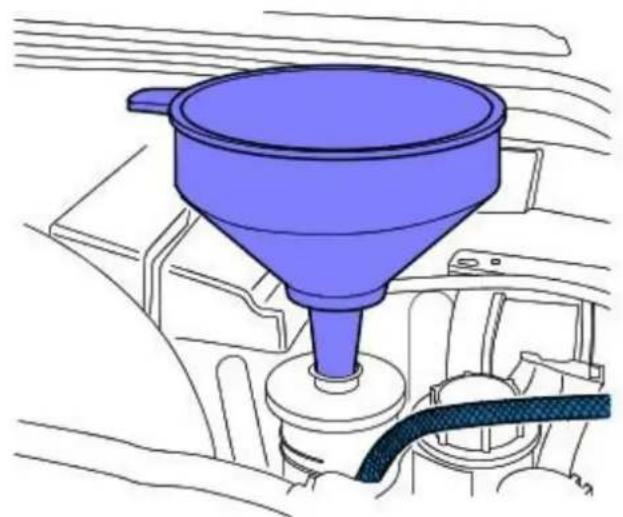
natural_image
Illustration of a blue funnel mounted on a vehicle engine compartment, with no visible text or symbols.E94372
- CAUTION: Be prepared to collect escaping fluids.
Remove the suitable funnel.

natural_image
Side profile illustration of a car with open hood and blue lock, no text or symbols present- CAUTION: Be prepared to collect escaping fluids.
Remove the suitable pipe to the power steering return hose.
- CAUTION: Be prepared to collect escaping fluids.
- NOTE: Note the orientation of the clip.
If a quick release coupling is fitted to the power steering return hose, connect the power steering fluid return hose to the coupling by installing the clip.
- Install a new power steering fluid reservoir. For additional information, refer to: (211-02)
Power Steering Fluid Reservoir - 4.2L/3.0L/2.7L Diesel (Removal and Installation),
Power Steering Fluid Reservoir - 3.0L Diesel (Removal and Installation).
Power Steering -
General Specifications
| Item Specification | |
| Power assisted steering fluid Dexron 2E |
Torque Specifications
| Description Nm lb-ft lb-in | |||
| Tie rod end retaining nut 35 26 - | |||
| Power steering pump retaining bolts 25 18 - | |||
| Extension shaft lower retaining bolt 27 20 - | |||
| Power steering gear actuator retaining bolts 3 - 27 | |||
| Power steering gear retaining bolts | 115 | 85 - | |
| Latch plate to pinion housing retaining bolt | 107 |

VUJ0003736
| Item Part Number Description | |
| 1 — Fluid cooler | |
| 2 — Low pressure pipe - fluid cooler to reservoir | |
| 3 — Fluid reservoir | |
| 4 — Power steering pump suction hose | |
| 5 — Power steering pump | |
| 6 — Heat shield | |
| 7 — Extension shaft | |
| 8 — Dash panel seal | |
| 9 — High pressure pipe | |
| 10 — Steering gear | |
| 11 — Tie-rod end | |
| 12 - Low pressure pipe - steering gear to fluid cooler | |
Vehicles with 2.0L or diesel engines
The power steering system uses a rack and pinion type, variable ratio steering gear. The power steering pump is belt driven on all model variants and the power steering oil cooler is of a wire bound tube type and is mounted in front of the radiator.
Vehicles with 2.5L or 3.0L engines
The power steering system uses a rack and pinion type, variable ratio steering gear with servotronic steering assistance. The power steering pump is belt driven on all model variants and the power steering oil cooler is of a wire bound tube type and is mounted in front of the radiator.
A variable steering rack ratio reduces the amount of turns from lock to lock to improve parking maneuvers without loosing any steering feel at higher speeds.
The steering assistance decreases smoothly at a calibrated rate to increase the steering efforts required as vehicle speed increases. The steering efforts are controlled by the servotronic valve (actuator) position, which in turn is controlled electronically by the servotronic ECU housed in the instrument cluster.
Absolute cleanliness must be observed when replenishing the fluid or dismantling any part of the system. New fluid from a sealed container must be used.
- NOTE: If the steering gear, pump or cooler are being replaced for leakage or noise related issues and there is no evidence of fluid contamination, there is no need to replace the reservoir. In some cases where the fluid clearly contains particulate matter, and the system continues to function, flush the system with fresh fluid and replace the reservoir, as there is the possibility that the reservoir internal filter may be damaged or faulty.
For additional information, refer to Section 211-00 Steering System - General Information.
Power Steering - Start Up Procedure After Power Steering Pump/ Gear Overhaul
General Procedures
- For additional information, refer to Section 211-00 Steering System - General Information.
Power Steering - Power Steering Control Valve Actuator2.5L NA V6 - AJV6/ 3.0L NA V6 - AJ27
Removal and Installation
Removal

natural_image
Technical line drawing of a mechanical component with a bolt and nut, no visible text or symbols- Raise and support the vehicle. For additional information, refer to Section 100-02 Jacking and Lifting.
- Remove the exhaust front muffler. For additional information, refer to Section 309-00 Exhaust System.
- Remove the heat shield.

natural_image
Technical line drawing of a mechanical component with a pointed tool and circular elements (no text or symbols)- Disconnect the electrical connector.

natural_image
Technical diagram of a mechanical assembly with directional arrows indicating motion or force (no text or symbols present)- Remove the actuator.
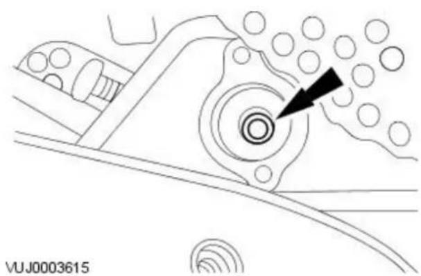
natural_image
Technical line drawing of a mechanical component with concentric circles and a black arrow pointing to a feature (no text or symbols)- Remove and discard the filter.
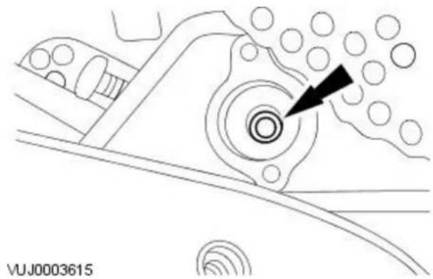
natural_image
Technical line drawing of a mechanical component with concentric circles and a black arrow pointing to a feature (no text or symbols)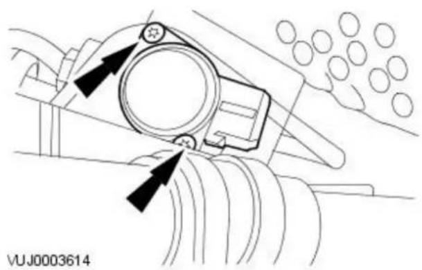
natural_image
Technical diagram of a mechanical component with directional arrows indicating motion or force (no text or symbols)-
To install, reverse the removal procedure.
-
Install a new filter
-
CAUTION: Make sure bolts are tightened evenly.
Tighten to 3 Nm.
Power Steering - Power Steering Fluid Cooler2.0L Duratorq-TDCi
Removal and Installation
Removal
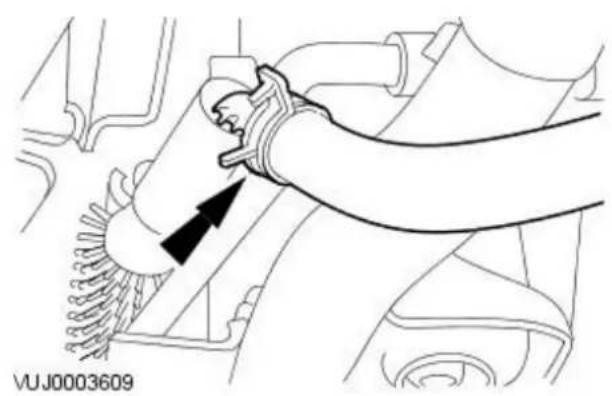
natural_image
Technical line drawing of a mechanical component with an arrow indicating direction (no text or symbols present)- Remove the radiator splash shield. For additional information, refer to For additional information, refer to: Radiator Splash Shield (501-02 Front End Body Panels, Removal and Installation).
-
Disconnect the power assisted steering oil cooler inlet and outlet hoses.
-
Left-hand side shown, right-hand side similar.
-
Drain the fluid into a suitable container.
-
Remove the power assisted steering oil cooler.
-
Remove the mounting bolts.
- Remove the power assisted steering oil cooler.

VUJ0003610
Installation
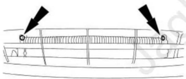
natural_image
Diagram of a mechanical component with two black arrows pointing to features, no text or symbols present- To install, reverse the removal procedure.
- Tighten to 7 Nm.
VUJ0003996
- NOTE: If the cooler is being replaced for leakage or noise related issues and there is no evidence of fluid contamination, there is no need to replace the reservoir.
In some cases where the fluid clearly contains particulate matter, and the system continues to function, flush the system with fresh fluid and replace the reservoir, as there is the possibility that the reservoir internal filter may be damaged or faulty.
Power Steering - Power Steering Fluid Cooler2.2L Duratorq-TDCi (110kW/150PS) - Puma
Removal and Installation
Removal
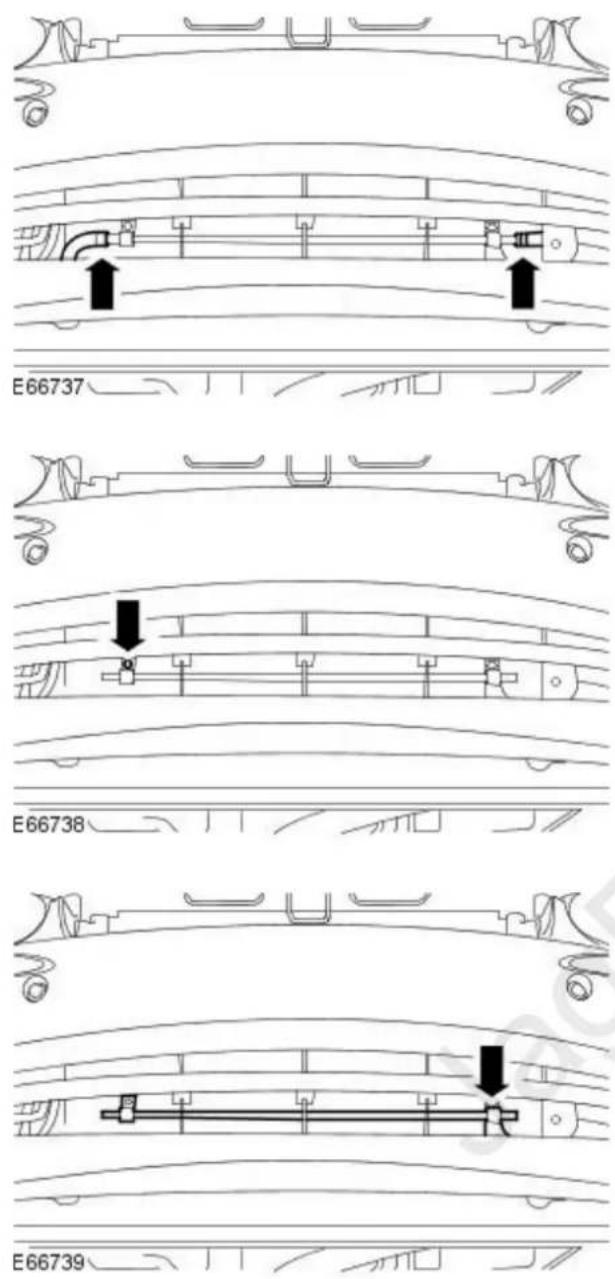
- Remove the radiator splash shield. For additional information, refer to: Radiator Splash Shield (501-02 Front End Body Panels, Removal and Installation).
- Disconnect the power steering fluid cooler hoses.
- Drain the fluid into a suitable container.
- Remove the power steering fluid cooler retaining bolt.
- Remove the power steering fluid cooler.
- Detach the power steering fluid cooler from the retaining clip.
Installation

natural_image
Technical line drawing of a mechanical component with no visible text or symbols- To install, reverse the removal procedure.
- Tighten to 7 Nm.
- NOTE: If the cooler is being replaced for leakage or noise related issues and there is no evidence of fluid contamination, there is no need to replace the reservoir.
In some cases where the fluid clearly contains particulate matter, and the system continues to function, flush the system with fresh fluid and replace the reservoir, as there is the possibility that the reservoir internal filter may be damaged or faulty.
Power Steering - Power Steering Fluid Reservoir
Removal and Installation
Removal

- CAUTION: If power steering fluid is spilt on the paintwork, the effected area must be immediately washed down with cold water.
Remove the power steering fluid reservoir.
- Disconnect the power steering supply and return hoses.
- Drain the fluid into a suitable container.
- Remove the power steering reservoir bolts.
- Remove the power steering reservoir.
Installation
- CAUTION: Use only Jaguar specification Dexron 2E power assisted steering oil.
To install, reverse the removal procedure. - Bleed the power steering system. For additional information, refer to Section 211-00 Steering System - General Information.
Power Steering - Power Steering Pump2.0L NA V6 - AJV6/ 2.5L NA V6 - AJV6/ 3.0L NA V6 - AJ27
Removal and Installation
Removal
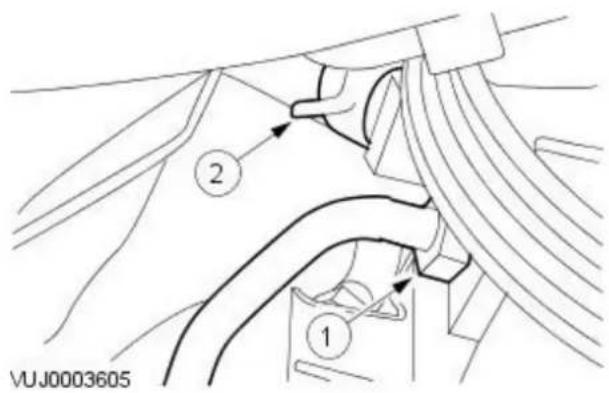
- Remove the accessory drive belt.
For additional information, refer to: Accessory Drive Belt - 2.0L NA V6 - AJV6/2.5L NA V6 - AJV6/3.0L NA V6 - AJ27 (303-05 Accessory Drive, Removal and Installation).

- CAUTION: Whenever the power steering pump unions are disconnected the steering gear valve body ports and hoses should be plugged to prevent dirt ingress.
Disconnect the power steering feed and high pressure hoses.
-
Disconnect the power steering high pressure hose.
-
Drain the fluid into a suitable container.
- Remove and discard the O-ring seal.
- Disconnect the power steering feed hose.
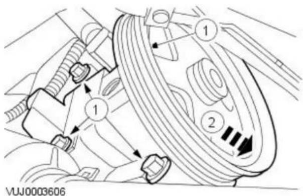
-
Remove the power steering pump.
-
Remove the power steering pump retaining bolts, power steering pump heat shield and high pressure pipe securing bracket.
-
Remove the power steering pump.
Installation

natural_image
Technical diagram of a mechanical pipe fitting with threaded end and coiled tubing, showing no text or symbols- To install, reverse the removal procedure.
• Install a new O-ring seal.

natural_image
Technical diagram of a mechanical assembly with no visible text or symbols
- CAUTION: Make sure the heat shield is fitted correctly and is free from damage.
Tighten to 25 Nm.
natural_image
Technical line drawing of a mechanical component with no visible text or symbols-
Tighten to 30 Nm.
-
NOTE: If the steering gear, pump or cooler are being replaced for leakage or noise related issues and there is no evidence of fluid contamination, there is no need to replace the reservoir.
In some cases where the fluid clearly contains particulate matter, and the system continues to function, flush the system with fresh fluid and replace the reservoir, as there is the possibility that the reservoir internal filter may be damaged or faulty.
Power Steering - Power Steering Pump2.0L Duratorq-TDCi/ 2.2L Duratorq-TDCi (110kW/ 150PS) - Puma
Removal and Installation
Materials
| Name | Specification |
| Grease | WSS-M12A4-A2 |
Removal
natural_image
Technical line drawing of an internal mechanical assembly with no visible text or symbols- Disconnect the battery ground cable. For additional information, refer to: Battery Disconnect and Connect (414-01 Battery, Mounting and Cables, General Procedures).
- Remove the air deflector. For additional information, refer to: Air Deflector - 2.0L Duratorq-TDCi/2.2L Duratorq-TDCi (110kW/150PS) - Puma (501-02 Front End Body Panels, Removal and Installation).
- Remove the air cleaner. For additional information, refer to: Air Cleaner (303-12B Intake Air Distribution and Filtering - 2.0L Duratorq-TDCi/2.2L Duratorq-TDCi (110kW/150PS) - Puma, Removal and Installation).
- Detach the generator and starter motor positive cable from the air cleaner mount bracket.

- Remove the air cleaner mount bracket.
natural_image
Mechanical assembly diagram showing a valve mechanism with no visible text or symbols- Detach the power steering pump belt.
- Rotate the power steering pump belt tensioner clockwise.

natural_image
Mechanical assembly diagram showing engine components and directional arrows (no text or labels)
natural_image
Technical diagram of an automotive engine showing internal components and a directional arrow (no text or labels)

-
Detach the power steering high-pressure pipe.
-
⚠️TION: Whenever the power steering pump feed hose is disconnected the power steering pump port and hose should be plugged to prevent dirt ingress. Failure to follow this instruction may result in damage to the vehicle.
- NOTE: Shown with the exhaust gas recirculation (EGR) cooler to EGR valve tube removed for clarity.
Disconnect the power steering feed hose.
- Drain the fluid into a suitable container.
- CAUTIONS:
Whenever the power steering high-pressure pipe union is disconnected the power steering pump port and pipe should be plugged to prevent dirt ingress. Failure to follow this instruction may result in damage to the vehicle.
Do not disconnect the quick release connector on the high-pressure pipe as it will not disconnect. Failure to follow this instruction may result in damage to the vehicle.
- NOTE: Shown with the EGR cooler to EGR valve tube removed for clarity.
Remove the power steering high-pressure pipe union from the power steering pump boss
- Remove and discard the O-ring seal.
- NOTE: Shown with the EGR cooler to EGR valve tube removed for clarity.
Remove the power steering pump retaining bolts.

natural_image
Technical line drawing of a mechanical assembly with no visible text or symbols- NOTE: Shown with the EGR cooler to EGR valve tube removed for clarity.
Remove the power steering pump securing bracket.

natural_image
Mechanical assembly diagram showing a motor and gear assembly with no visible text or symbols- NOTE: Shown with the EGR cooler to EGR valve tube removed for clarity.
Detach the power steering pump from the coolant pump.
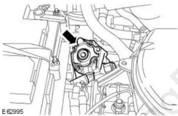
natural_image
Mechanical assembly diagram showing a gear mechanism with no visible text or symbols- Remove the power steering pump.

natural_image
Technical line drawing of an electric motor assembly with a gear and shaft (no text or symbols)- Remove and discard the water pump O-ring seal.
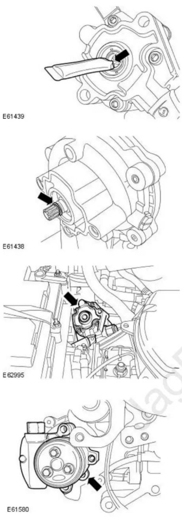
-
Coat the power steering pump drive splines with grease.
-
Install a new water pump O-ring seal.
-
Install the power steering pump.
-
NOTE: Shown with the EGR cooler to EGR valve tube removed for clarity. Attach the power steering pump to the coolant pump.


natural_image
Technical line drawing of a mechanical assembly with bolted components and mounting holes (no text or symbols)
natural_image
Technical line drawing of a mechanical component with a circular housing and bolted joints (no text or symbols)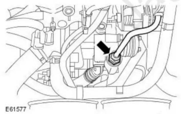
natural_image
Technical line drawing of a mechanical component with no visible text or symbols- NOTE: Shown with the EGR cooler to EGR valve tube removed for clarity. Install the power steering pump securing bracket.
- Tighten to 25 Nm.
- NOTE: Shown with the EGR cooler to EGR valve tube removed for clarity. Install the power steering pump retaining bolts.
- Tighten to 25 Nm.
- NOTE: Shown with the EGR cooler to EGR valve tube removed for clarity. Install the power steering pump retaining bolt.
- Tighten to 10 Nm.
- NOTE: Remove the plugs from the power steering pump port and the pipe.
- NOTE: Shown with the EGR cooler to EGR valve tube removed for clarity. Connect the power steering high-pressure pipe union.
• Install a new O-ring seal.
- Tighten to 30 Nm.

natural_image
Technical diagram of a mechanical assembly with no visible text or symbols- NOTE: Remove the plugs from the power steering pump port and the feed hose.
- NOTE: Shown with the EGR cooler to EGR valve tube removed for clarity. Connect the power steering feed hose.

natural_image
Technical diagram of an engine assembly showing valve and actuator components (no text or labels)- Attach the power steering high-pressure pipe.

natural_image
Mechanical assembly diagram showing linkage components with no visible text or symbols- Attach the power steering pump belt.
- Rotate the power steering pump belt tensioner clockwise.
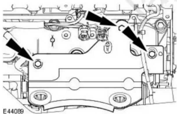
- Install the air cleaner mount bracket.
- Tighten to 25 Nm.

natural_image
Technical line drawing of a mechanical assembly with no visible text or symbols-
Attach the generator and starter motor positive cable to the air cleaner mounting bracket.
-
Install the air cleaner.
For additional information, refer to: Air Cleaner (303-12B Intake Air Distribution and Filtering - 2.0L Duratorq-TDCi/2.2L Duratorq-TDCi (110kW/150PS) - Puma, Removal and Installation).
- Install the air deflector.
For additional information, refer to: Air Deflector - 2.0L Duratorq-TDCi/2.2L Duratorq-TDCi (110kW/150PS) - Puma (501-02 Front End Body Panels, Removal and Installation).
- Connect the battery ground cable.
For additional information, refer to: Battery Connect (414-01 Battery, Mounting and Cables, General Procedures).
- NOTE: If the pump is being replaced for leakage or noise related issues and there is no evidence of fluid contamination, there is no need to replace the reservoir.
In some cases where the fluid clearly contains particulate matter, and the system continues to function, flush the system with fresh fluid and replace the reservoir, as there is the possibility that the reservoir internal filter may be damaged or faulty.
Power Steering - Steering Gear2.0L Duratorq-TDCi/ 2.2L Duratorq-TDCi (110kW/ 150PS) - Puma
Removal and Installation
Removal
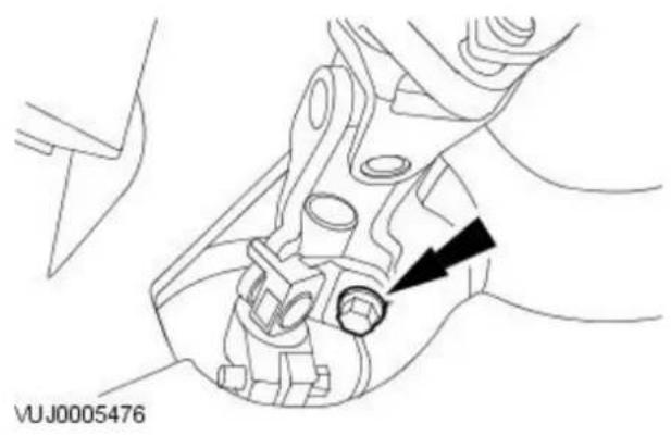
natural_image
Technical line drawing of a mechanical assembly with no visible text or symbols- Center the steering wheel.
- Lock in position and remove the ignition key.
- Remove and discard the extension shaft lower retaining bolt.

natural_image
Technical line drawing of a mechanical assembly with a tool inserted, showing no text or symbols- NOTE: Right-hand shown, left-hand similar.
Release both tie-rod end ball joints.
-
loosen the locknut.
-
Release both track rods from tie rod ends, note the number of turns for installation.

-
Remove the air deflector. For additional information, refer to: Air Deflector - 2.0L Duratorq-TDCi/2.2L Duratorq-TDCi (110kW/150PS) - Puma (501-02 Front End Body Panels, Removal and Installation).
-
Disconnect the steering gear fluid lines.
-
Remove the latch plate bolt.
-
Rotate latch plate counter clockwise.
-
Disconnect the steering gear fluid lines.

natural_image
Technical line drawing of a vehicle engine component with no visible text or symbols- Detach the steering gear cooler pipe.
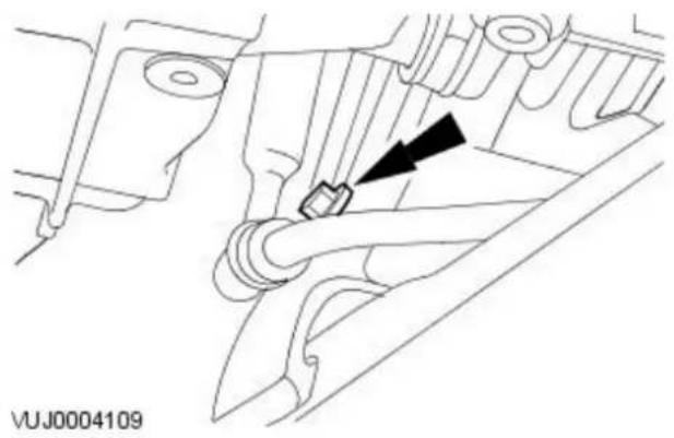
natural_image
Technical diagram of a mechanical component with a black arrow pointing to a specific part (no text or symbols present)- Detach the steering gear cooler pipe.

natural_image
Medical illustration showing a surgical procedure with an arrow pointing to a component (no text or symbols present)- Detach the right-hand side of the steering gear.

natural_image
Technical line drawing of a mechanical assembly with no visible text or symbols- Detach the left-hand side of the steering gear.

-
Remove the bulk head panel seal.
-
Reposition the steering gear.
- Remove the bulk head panel seal.
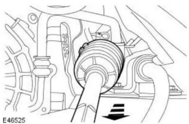
natural_image
Technical line drawing of a mechanical assembly with a central bearing and shaft (no text or symbols)- Remove the steering gear.
Installation

natural_image
Mechanical assembly diagram showing a shaft and bearing component (no text or labels)- Install the steering gear.

-
Reposition the steering gear.
-
Install the bulk head panel seal.
- Reposition the steering gear.

natural_image
Technical line drawing of a mechanical assembly with no visible text or symbols- Attach the left-hand side of the steering gear.
- Tighten to 133 Nm.

natural_image
Medical illustration showing a surgical procedure with an arrow pointing to a component (no text or symbols present)- Attach the right-hand side of the steering gear.
- Tighten to 133 Nm.

natural_image
Technical diagram of a mechanical component with a black arrow pointing to a specific part (no text or symbols present)- Attach the steering gear cooler pipe.

natural_image
Technical line drawing of a vehicle engine bay with no visible text or symbols- Attach the steering gear cooler pipe.

natural_image
Technical diagram of a mechanical assembly with no visible text or symbols- Install new O-ring seals.

natural_image
Technical line drawing of a mechanical component with no visible text or symbols- Attach the steering gear fluid lines.
- Tighten to 10 Nm .
- Install the air deflector.
For additional information, refer to: Air Deflector - 2.0L Duratorq-TDCi/2.2L Duratorq-TDCi (110kW/150PS) - Puma (501-02 Front End Body Panels, Removal and Installation).

- NOTE: Right-hand shown, Left hand similar.
Connect tie-rod end ball joints.
- Attach both tie rods to previously noted positions.
-
Tighten the tie rod locking nut.
-
NOTE: Install a new bolt.
Attach the lower steering column.
- Tighten to 25 Nm.
- Carry out steering system bleed procedure.
For additional information, refer to: Power Steering System Filling (211-00 Steering System - General Information, General Procedures).
- NOTE: If the steering gear is being replaced for leakage or noise related issues and there is no evidence of fluid contamination, there is no need to replace the reservoir.
In some cases where the fluid clearly contains particulate matter, and the system continues to function, flush the system with fresh fluid and replace the reservoir, as there is the possibility that the reservoir internal filter may be damaged or faulty.
- If a new steering gear has been installed carry out the front toe adjustment procedure.
For additional information, refer to: Front Toe Adjustment (204-00 Suspension System - General Information, General Procedures).
Power Steering - Steering Gear2.0L NA V6 - AJV6/ 2.5L NA V6 - AJV6/ 3.0L NA V6 - AJ27
Removal and Installation
 |
Removal
All vehicles
- Center the steering wheel.
- Lock in position and remove the ignition key.
- Remove the steering column coupling. For additional information, refer to: Steering Column Coupling (211-04 Steering Column, Removal and Installation).
Right-hand drive vehicles
- Remove the right-hand wheel arch liner access cover.

All vehicles

natural_image
Technical line drawing of a mechanical assembly with no visible text or symbols- NOTE: Right-hand shown, left-hand similar.
Release both tie-rod end ball joints.
- Loosen the locknuts.
- Release both track rods from the tie rod ends, note number of turns for installation.

natural_image
Technical line drawing of a mechanical component with a tool and directional arrow (no text or symbols)- Disconnect the power steering control valve actuator electrical connector (if equipped).
Vehicles with high intensity discharge headlamps
- Detach the link rod from the headlamp leveling sensor.
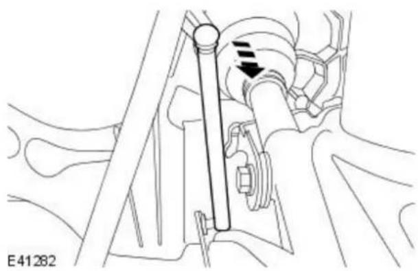
natural_image
Mechanical assembly diagram showing a shaft and gear mechanism (no text or labels)All vehicles

natural_image
Technical diagram of a mechanical assembly with a black arrow pointing to a component (no text or symbols present)- Detach the power steering high pressure pipe.
Vehicles with automatic transmission
- Detach the selector lever cable.
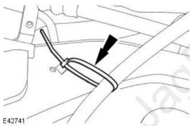
natural_image
Mechanical component diagram showing a lever and cable assembly (no text or symbols)All vehicles

- Install the special tool.

natural_image
Technical line drawing of a mechanical assembly with bolts and a directional arrow (no text or symbols)
natural_image
Technical line drawing of a mechanical component with two black arrows pointing to specific features (no text or symbols present)
natural_image
Technical line drawing of a mechanical component with a black arrow pointing to a circular feature (no text or symbols)
natural_image
Line drawing of a mechanical assembly with hands operating a component (no text or symbols)E50621
- NOTE: Left-hand shown, right-hand similar.
Position and adjust the special tool rear height adjuster.
- NOTE: Left-hand shown, right-hand similar.
Remove the front subframe reinforcement plate retaining bolts.
- NOTE: Left-hand shown, right-hand similar.
Remove the front subframe rear mount retaining bolts.

- WARNING: Rotate the special tool height adjustment valve slowly. Failure to follow this instruction may result in personal injury.
Using the special tool, lower the front subframe to a maximum of 50 mm (1.97 inches).

natural_image
Technical line drawing of a mechanical assembly with no visible text or symbols- Remove the retaining clip from the power steering high and low pressure pipes.
All vehicles

- CAUTION: Whenever the power steering pipes are disconnected, the steering gear valve body ports and power steering pipes should be plugged to prevent dirt ingress. Failure to follow this instruction may result in damage to the vehicle.
- NOTE: Left-hand drive vehicles shown, right-hand drive vehicles similar.
Disconnect the power steering high and low pressure pipes from the steering gear.
- Remove the latch plate retaining bolt.
- Disconnect the power steering high pressure pipe.
- Disconnect the power steering low pressure pipe.
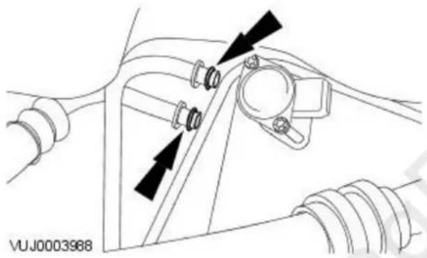
natural_image
Technical diagram of a mechanical assembly with no visible text or symbols- Remove and discard the O-ring seals.
Right-hand drive vehicles
- Remove the power steering high pressure pipe bracket retaining bolt.
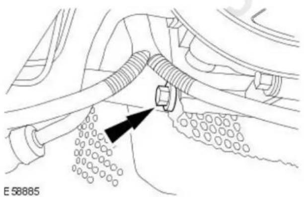
natural_image
Technical diagram of a mechanical assembly with hoses and a bolt, showing no readable text or symbols.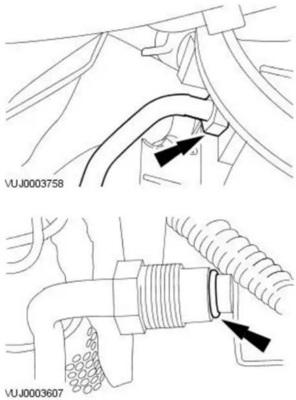
- CAUTION: Whenever the power steering high pressure pipe is disconnected, the power steering pump port and pipe should be plugged to prevent dirt ingress. Failure to follow this instruction may result in damage to the vehicle.
Disconnect the power steering high pressure pipe from the power steering pump.
- Remove and discard the O-ring seal.
All vehicles
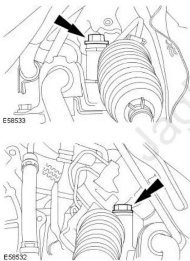
- NOTE: Left-hand drive vehicles shown, right-hand drive vehicles similar.
Detach the right-hand side of the steering gear.
- NOTE: Left-hand drive vehicles shown, right-hand drive vehicles similar.
Detach the left-hand side of the steering gear.

natural_image
Technical line drawing of a mechanical assembly with no visible text or symbols
natural_image
Technical diagram of a mechanical assembly with labeled components and an arrow indicating direction (no readable text or symbols)- NOTE: Left-hand drive vehicles shown, right-hand drive vehicles similar.
Remove the steering gear bulkhead seal.
- NOTE: Left-hand drive vehicles shown, right-hand drive vehicles similar.
Remove the steering gear.
- Rotate the steering gear.
- Remove the steering gear through the driver side wheel arch aperture.
Installation
All vehicles
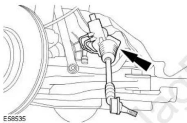
natural_image
Technical diagram of a mechanical assembly with labeled components and an arrow indicating direction (no readable text or symbols)- NOTE: Left-hand drive vehicles shown, right-hand drive vehicles similar. Install the steering gear.

natural_image
Technical line drawing of a mechanical assembly with no visible text or symbols- CAUTION: Make sure the steering gear bulkhead seal is correctly aligned. Failure to follow this instruction may result in damage to the vehicle.
- NOTE: Left-hand drive vehicles shown, right-hand drive vehicles similar. Install the steering gear bulkhead seal.

natural_image
Technical line drawing of a mechanical assembly with no visible text or symbols
natural_image
Technical line drawing of a mechanical assembly with no visible text or symbols
natural_image
Technical line drawing of a mechanical assembly with no visible text or symbols
natural_image
Technical line drawing of mechanical components with no visible text or symbols- NOTE: Left-hand drive vehicles shown, right-hand drive vehicles similar. Attach the right-hand side of the steering gear.
- Loosely install the steering gear retaining bolt.
- NOTE: Left-hand drive vehicles shown, right-hand drive vehicles similar. Attach the left-hand side of the steering gear.
- Loosely install the steering gear retaining bolt.
- NOTE: Left-hand drive vehicles shown, right-hand drive vehicles similar. Tighten the right-hand side steering gear retaining bolt.
- Tighten to 115 Nm.
- NOTE: Left-hand drive vehicles shown, right-hand drive vehicles similar. Tighten the left-hand side steering gear retaining bolt.
- Tighten to 115 Nm.
Right-hand drive vehicles

natural_image
Technical line drawing of a pipe fitting with threaded connectors and tubing (no text or symbols)
natural_image
Technical line drawing of a mechanical component with no visible text or symbols
natural_image
Technical diagram of a mechanical assembly with hoses and a connector, no visible text or symbolsAll vehicles

natural_image
Technical diagram of a mechanical assembly with no visible text or symbols
- NOTE: Remove the blanking plug.
Install a new O-ring seal.
- NOTE: Remove the blanking plug.
Connect the power steering high pressure pipe to the power steering pump.
- Tighten to 30 Nm
- Install the power steering high pressure pipe bracket retaining bolt.
- Tighten to 25 Nm
-
Install new O-ring seals.
-
NOTE: Left-hand drive vehicles shown, right-hand drive vehicles similar.
- NOTE: Remove the blanking plugs.
Connect the power steering high and low pressure pipes to the steering gear.
- Connect the power steering low pressure pipe.
- Connect the power steering high pressure pipe.
- Install the latch plate retaining bolt
- Tighten to 10 Nm.
Left-hand drive vehicles
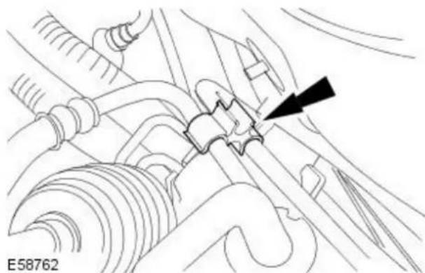
natural_image
Technical line drawing of a mechanical assembly with no visible text or symbols- Install the retaining clip to the power steering high and low pressure pipes.
All vehicles

- Using the special tool raise the front subframe.

natural_image
Technical line drawing of a mechanical component with a black arrow pointing to a circular feature (no text or symbols)- NOTE: Left-hand shown, right-hand similar.
Loosely install the front subframe rear mount retaining bolts.

natural_image
Technical line drawing of a mechanical component with two black arrows pointing to specific parts (no text or symbols present)- NOTE: Left-hand shown, right-hand similar.
Loosely install the front subframe reinforcement plate retaining bolts.

natural_image
Technical line drawing of a mechanical component with a black arrow pointing to a specific part (no text or symbols present)- NOTE: Left-hand shown, right-hand similar. Tighten to 142 Nm.
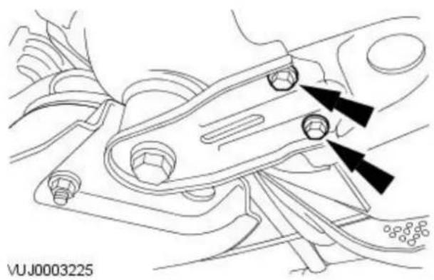
natural_image
Technical line drawing of a mechanical component with two black arrows pointing to specific features (no text or symbols present)- NOTE: Left-hand shown, right-hand similar. Tighten the front subframe reinforcement bolts.
M8 to 35 Nm.
M10 to 70 Nm.

- Remove the special tool.
Vehicles with automatic transmission
- Attach the selector lever cable.
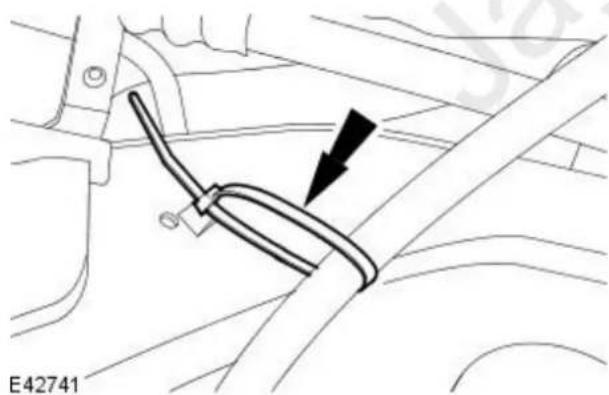
natural_image
Technical diagram of a car interior showing a cable and lever mechanism (no text or symbols)All vehicles
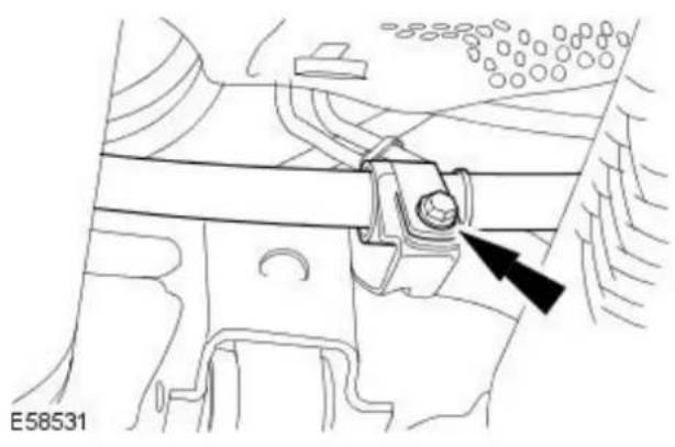
natural_image
Technical diagram of a mechanical assembly with a black arrow pointing to a component (no text or symbols present)- Attach the power steering high pressure pipe.
Vehicles with high intensity discharge headlamps
- Attach the link rod to the headlamp leveling sensor.

natural_image
Mechanical assembly diagram showing a shaft and bearing mechanism (no text or labels)All vehicles
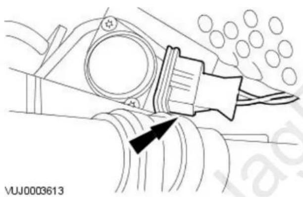
natural_image
Technical line drawing of a mechanical component with a highlighted section and arrow indicator (no readable text or symbols)- Connect the power steering control valve actuator electrical connector (if equipped).

natural_image
Mechanical assembly diagram showing a lever mechanism with a black arrow indicating direction (no text or symbols present)- NOTE: Right-hand shown, left-hand similar.
Connect tie-rod end ball joints.
- Attach both tie rod ends to previously noted positions.
- Tighten tie rod locking nut.
Right-hand drive vehicles
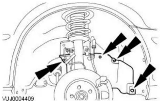
natural_image
Technical diagram of a vehicle suspension system with mounting brackets and wiring (no text or symbols)- Install the right-hand wheel arch liner access cover.
All vehicles
- Carry out steering system bleed procedure.
For additional information, refer to: Power Steering System Filling (211-00 Steering System - General Information, General Procedures).

- CAUTION: Make sure the steering column coupling is installed with the vehicle on its wheels. Failure to follow this instruction may result in damage to the vehicle.
Install the steering column coupling.
For additional information, refer to: Steering Column Coupling (211-04 Steering Column, Removal and Installation).
- NOTE: If the steering gear is being replaced for leakage or noise related issues and there is no evidence of fluid contamination, there is no need to replace the reservoir.
In some cases where the fluid clearly contains particulate matter, and the system continues to function, flush the system with fresh fluid and replace the reservoir, as there is the possibility that the reservoir internal filter may be damaged or faulty.
- Using the Jaguar approved diagnostic system, configure the steering angle sensor.
Steering Linkage -
Torque Specifications
| Description Nm lb-ft lb-in | |||
| Tie-rod end retaining nut 35 26 - | |||
| Tie-rod end lock nut 40 30 - | |||
| Wheel nuts - Vehicles with steel wheels 80 59 - | |||
| Wheel nuts - Vehicles with aluminium wheels 103 76 - |
Steering Linkage - Steering Linkage
Description and Operation

VUJ0003799
| Item Part Number Description | |
| 1 — Steering gear | |
| 2 — Tie-rod end boot | |
| 3 — Tie-rod | |
| 4 — Tie-rod end | |
| 5 — Wheel hub assembly | |
| 6 — Tie-rod end retaining nut | |
| 7 — Tie-rod end lock nut |
The left and right-hand tie-rod assemblies:
● Transmit steering forces from the steering gear to the wheel hubs.
- Provide front road wheel toe setting by adjustment of the threaded outer tie-rod ends.
- NOTE: Steering geometry adjustments must only be carried out with the vehicle on turn plates to allow the wheels to move during adjustment.
The left and right-hand steering rack boots:
- Are installed between the steering rack and the tie-rod ends.
- Are of the concertina type.
- Retain lubricant and prevent the ingress of foreign matter.
For additional information, refer to Section 211-00 Steering System - General Information.
Removal
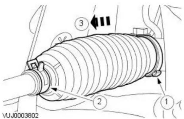
- Remove the tie-rod end. For additional information, refer to procedure in this section: Tie Rod End
-
Remove the steering gear boot.
-
Remove and discard the steering gear boot retaining clamp.
- Detach the steering gear boot retaining clamp.
- Remove the steering gear boot.
Installation
- CAUTION: Make sure the steering gear is clean before installing the boot.
To install, reverse the removal procedure.
• Install the steering gear boot using a new retaining clamp.
Steering Linkage - Tie Rod End
Removal and Installation
| Special Tool(s) | |
 204-192 204-192 | Seperator, Ball Joint204-192 (JD-219) |
Removal

natural_image
Mechanical assembly diagram showing a bolted joint with bolts and a black arrow pointing to a specific component (no text or symbols present)- Remove the wheel and tire. For additional information refer to Section 204-04 Wheels and Tires.
-
Loosen the tie-rod end lock nut.
-
Remove the tie-rod end retaining nut.

natural_image
Technical line drawing of a mechanical assembly with no visible text or symbols- NOTE: When the tie-rod end is seperated from the wheel hub assembly, the ball joint seal should be protected to prevent damage.
Using the special tool, detach the tie-rod end.


natural_image
Mechanical assembly diagram showing a shaft and bolt assembly with no visible text or symbols- NOTE: Make a note of the number of turns required to remove the tie-rod end.
Remove the tie-rod end.
Installation

natural_image
Technical line drawing of a mechanical assembly with bolts and components (no text or symbols)- NOTE: Make sure the tie-rod end is installed on the tie-rod by the same amount of turns used to remove it.
To install, reverse the removal procedure.
- Tighten to 40 Nm.
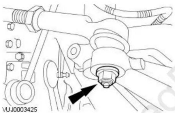
natural_image
Technical line drawing of a mechanical assembly with no visible text or symbols-
Tighten to 35 Nm.
-
Check the toe adjustment. For additional information, refer to Section 204-00 Suspension System - General Information.
Torque Specifications
| Description Nm lb-ft lb-in | |||
| Steering wheel retaining bolt 47 35 - | |||
| Steering column lower retaining bolt 25 18 - | |||
| Steering column retaining bolts 24 18 - | |||
| Steering column flexible coupling retaining bolt. 25 18 – |
Steering Column - Steering Column
Description and Operation

VUJ0005478
| Item Part Number Description | |
| 1 — Steering column | |
| 2 — Steering wheel | |
| 3 — Steering wheel angle sensor | |
| 4 — Steering column flexible coupling |
The steering column lock is secured to the upper casting of the steering column and consists of a locking pin. The steering column is locked and unlocked by inserting and removing the ignition key respectively.
The steering column has tilt and telescope functions. These allow the driver to manually set the steering column position by using the tilt/telescope lever, regardless of the ignition switch position. The steering column is capable of being tilted up or tilted down and telescoped in or out, and is unlocked and locked into position using a single lever located on the underside of the steering column.
The lower part of the steering column consists of two shafts. The lower flexible coupling shaft is attached to both the steering gear and the upper shaft.
No routine maintenance of the steering wheel is required. Any setting of steering wheel for misalignment must be achieved by adjusting the tie rods.
For additional information, refer to Section 211-00 Steering System - General Information.
Steering Column - Ignition Switch Lock Cylinder
Removal and Installation
Removal
natural_image
Diagram of a car interior showing dashboard and seat area with a directional arrow (no text or symbols)- Remove the driver side instrument panel lower trim panel pocket.

- Remove the drivers side instrument panel lower trim panel.

natural_image
Interior view of a car dashboard and steering wheel (no text or symbols visible)- Remove the steering column lower shroud.

natural_image
Technical line drawing of a car interior showing a steering wheel and dashboard (no text or symbols)-
Remove the ignition switch lock cylinder.
-
Turn the ignition key to position 1.
- Press the locking pin.
- Remove the ignition switch lock cylinder.
Installation
- To install, reverse the removal procedure.
Removal
All vehicles
- Remove the clockspring. For additional information, refer to: Clockspring (501-20B Supplemental Restraint System, Removal and Installation).
Vehicles without Driver Lower Airbag Module
- Remove the driver side instrument panel lower trim panel.

natural_image
Diagram showing a curved surface with contour lines and a directional arrow, no readable text or symbols present.Vehicles with Driver Lower Airbag Module
- Remove the driver lower airbag module. For additional information, refer to: Driver Lower Air Bag Module (501-20B Supplemental Restraint System, Removal and Installation).
All vehicles

-
Disconnect the ignition switch electrical connector.
-
Disconnect the passive anti-theft system transceiver electrical connector.
- Disconnect the ignition switch electrical connector.

- Reposition the steering column wiring harness bracket.
- Remove the steering column wiring harness bracket retaining screw.
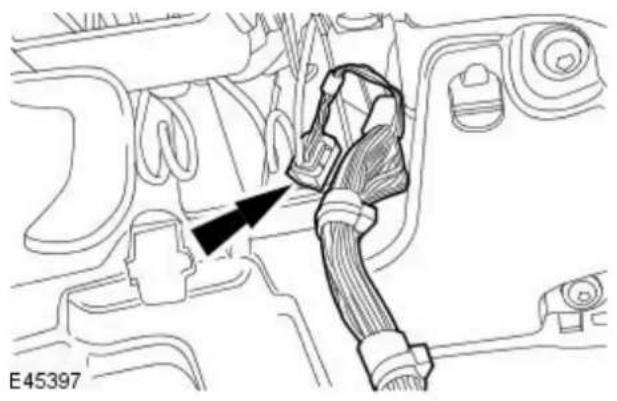
natural_image
Technical line drawing of a vehicle's internal components with a black arrow pointing to a cable or connector (no text or symbols present)- Disconnect the steering wheel rotation sensor electrical connector.
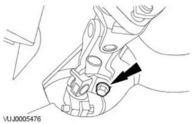
natural_image
Mechanical assembly diagram showing a hand holding a component with an arrow pointing to a circular feature (no text or symbols present)- Remove and discard the steering column lower retaining bolt.
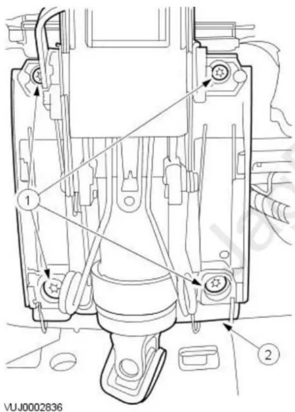
-
Remove the steering column.
-
Remove the steering column retaining bolts.
- Remove the steering column.
Installation
- To install, reverse the removal procedure.
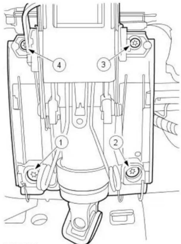
VUJ0005551
- Tighten in the sequence shown.
- Tighten to 24 Nm.

natural_image
Mechanical assembly diagram showing a valve mechanism with a black arrow pointing to a component (no text or labels present)VUJ0005476
- Install a new bolt.
- Tighten to 25 Nm.
Steering Column - Steering Column Coupling
Removal and Installation
Removal

natural_image
Mechanical assembly diagram showing a component with a black arrow pointing to a circular feature, no readable text or symbols present.- Remove and discard the steering column lower retaining bolt.
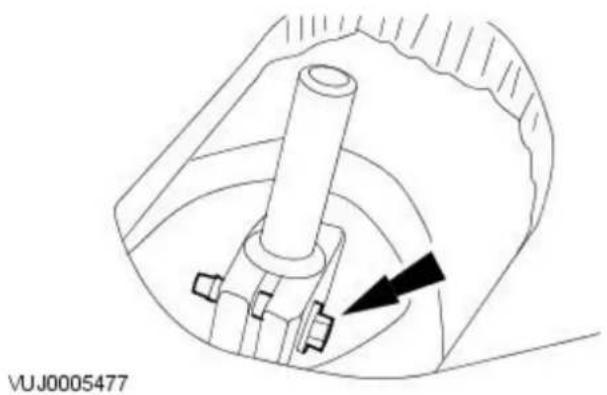
natural_image
Technical diagram of a mechanical assembly with a cylindrical component and directional arrow (no text or symbols)- Remove the steering column coupling.
Installation
natural_image
Technical line drawing of a mechanical component with no visible text or symbols- To install, reverse the removal procedure.
- Tighten to 25 Nm.

natural_image
Technical line drawing of a mechanical assembly with no visible text or symbols- Install a new bolt.
- Tighten to 25 Nm.
Removal

natural_image
Top-down schematic of a car interior showing steering wheel and dashboard components with an arrow pointing to a specific component (no text or symbols present)- Position the front wheels in a straight ahead position and centralize steering wheel.
- Remove the driver airbag module. For additional information, refer to: Driver Air Bag Module (501-20B Supplemental Restraint System, Removal and Installation).
- Disconnect the electrical connector.

natural_image
Top-down schematic of a car's steering wheel and dashboard (no text or symbols)-
Remove the steering wheel.
-
Using suitable insulation/masking tape, secure the clockspring to prevent movement from the centralized position.
Installation

natural_image
Top-down technical diagram of a car's steering wheel and dashboard (no text or symbols)- To install, reverse the removal procedure.
- Tighten to 47 Nm.
Steering Column Switches - Steering Column Switches
Description and Operation
Steering Column Multifunction Switch RH
The steering column multifunction switch RH controls the following functions when the ignition switch is in position II:
Flick Wipe
Flick wipe operation:
- Is obtained by pulling the switch stalk towards the driver.
- Features continuous wipe action at slow speed while the switch stalk position is held.
Intermittent Wipe
In the intermittent wipe position:
- The wiper operates intermittently, with a variable time delay between wipes.
- The time delay may be varied by rotating the column switch collar. This switch has six positions and varies the delay between 1 and 22 seconds. The collar is turned counter-clockwise to increase the delay.
Slow Speed Wiper
In the slow speed position:
- The wiper operates continuously at slow speed.
High Speed Wiper
In the high speed position:
- The wiper operates continuously at high speed.
Windscreen Wash/ Wipe
The wash/wipe function:
- Is operated by the button at the end of the switch stalk.
- If the switch stalk is in the off or intermittent position the washers will operate for the duration the button is being pressed. The wipers will operate at the slow speed while the button is being pressed and provides an additional three sweeps of the wipers after the button is released.
- If the switch stalk is in the flick, slow or high speed position the washers will operate for the duration the button is being pressed. The wipers will operate at the slow or high speed respectively while the button is being pressed.
- Is disabled if the 'Washer Fluid Low' message is displayed but manual operation is still available.
Headlamp Power Wash (if equipped)
The headlamp power wash function:
- Operates only when the headlamps are on and the windscreen wash/wipe button is pressed.
- Provides one short burst to the headlamps for approximately 0.5 of a second.
After the initial application, the headlamp power wash operates on every fifth operation of the wash/wipe button.
Rain Sensing/ Auto Wipe (if equipped)
The rain sensing/auto wipe function:
- Operates if the wash/wipe switch is set to the intermittent position and the variable delay is adjusted to the minimum position. If any other position is selected the rain sensing function is disabled and the system reverts to the intermittent function with position two being the shortest delay.
- When rain sensing/auto wipe is selected the area of the windscreen covered by the rain sensor is monitored for moisture. If moisture is detected the wipers are activated. The speed of the wipers is dependent on the amount of moisture detected on the windscreen. When the windscreen is dry the wipers are parked until moisture is detected again.
Steering Column Multifunction Switch LH
The steering column multifunction switch LH controls the following functions when the ignition switch is in position II:
Direction Indicators
The direction indicators:
- Operate when the ignition switch is in position II.
- Are operated by moving the switch stalk up or down until it latches in position to indicate a right or left turn respectively.
- May be operated while the switch stalk is held against spring pressure before reaching the latched position.
- Cancel automatically upon completion of a turn. The multifunction switch LH stalk then returns to the center position.
An audible ticking and a flashing green warning lamp on the instrument cluster indicates that the direction indicators are operating. If an indicator bulb fails, the warning lamp and ticking operate at twice the normal rate.
Main Beam
The main beam switch has two pull positions. Operating the switch to the first position and then releasing it will cause the main beam to flashed. The main beam can be flashed with the ignition on or off and will remain activated as long as the switch is held.
Operating the switch to the second position will operate main beam continuously if the headlamps are on.
Steering Column Switches - Steering Column Switches
Diagnosis and Testing
Inspection and Verification
- Verify the customer concern.1.
- Visually inspect for obvious signs of electrical damage.2.
Visual Inspection Chart
| Electrical |
| Wiring harness for damage or corrosion |
| Electrical connector(s) |
| Switch(s) |
| Relay(s) |
| Module |
-
- If an obvious cause for an observed or reported concern is found, correct the cause (if possible) before proceeding to the next step.
-
- If the cause is not visually evident, verify the symptom and refer to the Jaguar Approved Diagnostic System.
Steering Column Switches - Steering Column Multifunction Switch LH
Removal and Installation
Removal

natural_image
Diagram of a car interior showing dashboard and seat area with a directional arrow (no text or symbols)- Remove the driver side instrument panel lower trim panel pocket.
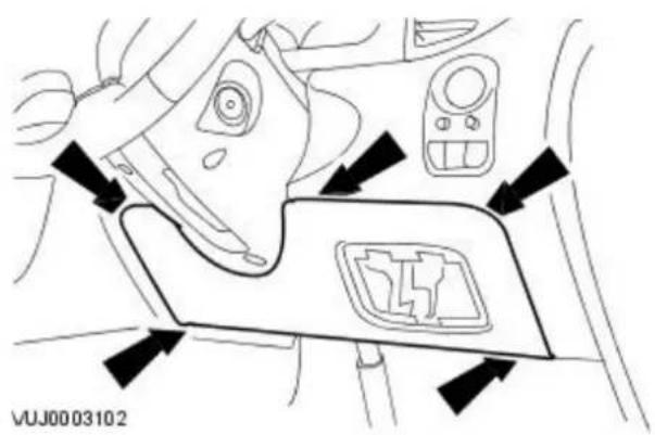
- Remove the driver side instrument panel lower trim panel.

- Remove the steering column lower shroud.
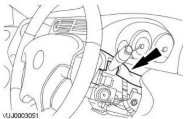
natural_image
Technical diagram of a car interior showing steering wheel and gear mechanism (no text or symbols)- Remove the steering column upper shroud.

natural_image
Technical line drawing of a mechanical component with no visible text or symbols- Detach the steering column multifunction switch left-hand.
- Release the retaining tang.
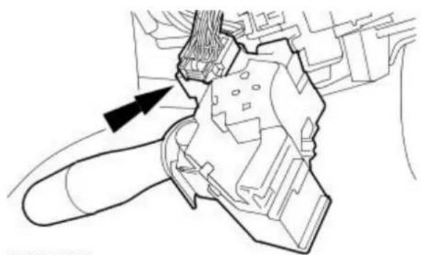
natural_image
Technical line drawing of a mechanical component with an arrow indicating direction (no text or symbols)- Remove the steering column multifunction switch left-hand.
- Disconnect the electrical connector.
Installation
- To install, reverse the removal procedure.
Steering Column Switches - Steering Column Multifunction Switch RH
Removal and Installation
Removal

natural_image
Technical line drawing of a mechanical component with a black arrow pointing to a curved section (no text or symbols)- Lower the steering column.
- Remove the steering column upper shroud.

natural_image
Technical line drawing of a mechanical component with a hand operating a lever (no text or symbols)- Detach the steering column multifunction switch right-hand.
- Release the retaining tang.

natural_image
Technical line drawing of a mechanical component with an arrow indicating a directional flow (no text or symbols present)- Remove the steering column multifunction switch right-hand.
- Disconnect the electrical connector.
Installation
- To install, reverse the removal procedure.
Engine System - General Information -
General specifications 2.0 litre diesel.
| Item Specification | |
| Code FMBA/FMBB | |
| Firing order 1-3-4-2 | |
| Cylinder bore diameter 86 mm | |
| Stroke 86 mm | |
| Displacement 1998 cc | |
| Compression ratio 19:1 | |
| Engine weight 195 kg (excluding front end accessory drive) | |
| Power output at 3800 rpm 96 kW (130 PS) | |
| Torque at 1800 rpm 325 Nm | |
| Idle speed 900 rpm |
General specifications 2.2 litre diesel.
| Item Specification | |
| Code QJBA | |
| Firing order | 1-3-4-2 |
| Cylinder bore diameter | 86 mm |
| Stroke | 94.6 mm |
| Displacement | 2198 cc |
| Compression ratio | 19:1 |
| Power output at 3800 rpm | 114 kW (155 PS) |
| Torque at 1800 rpm | 360 Nm |
| Idle speed | 800 rpm |
General specifications 2.0 litre.
| Item Specification | |
| Displacement in liters | 2.099 |
| Number of cylinders | 6 |
| Bore and stroke (mm) | $1.6 x 66.84 |
| Firing order | 1,4,2,5,3,6 |
| Compression ratio | 10.75:1 |
General specifications 2.5 litre.
| Item Specification | |
| Displacement in liters | 2.495 |
| Number of cylinders | 6 |
| Bore and stroke (mm) | $1.6 x 79.5 |
| Firing order | 1,4,2,5,3,6 |
| Compression ratio | 10.3:1 |
General specifications 3.0 litre.
| Item Specification | |
| Displacement in liters | 2.967 |
| Number of cylinders | 6 |
| Bore and stroke (mm) | 89.0 x 79.5 |
| Firing order | 1,4,2,5,3,6 |
| Compression ratio | 10.5:1 |
Cylinder Block Dimensions 2.0 litre and 2.2 litre diesel.
| Description | mm |
| Cylinder bore diameter – Class 1 | 86·000 - 86·010 |
| Cylinder bore diameter – Class 2 | 86·010 - 86·020 |
| Cylinder bore diameter – Class 3 | 86·020 - 86·030 |
| Main bearing shells 1 to 4 – inside diameter (bearings installed) | 65·003 - 65·030 |
| Main bearing shells 5 – inside diameter (bearings installed) | 70·004 - 70·033 |
| Main bearings 1 to 4 – radial clearance | 0·033 - 0·080 |
| Main bearing 5 – radial clearance | 0·034 - 0·083 |
| Main bearings 1 to 4 – parent bore diameter – vertical measurement | 64·504 - 64·520 |
| Main bearing 5 – parent bore diameter – vertical measurement | 74·504 - 74·520 |
| Main bearings 1 to 4 – parent bore diameter – horizontal measurement | 69·502 - 69·525 |
| Main bearing 5 – parent bore diameter – horizontal measurement | 74·502 - 74·525 |
Piston Dimensions 2.0 litre and 2.2 litre diesel.
| Description | m m |
| Piston cooling code | 6 |
| Piston diameter – Class A | 85·94 - 85·95 |
| Piston diameter – Class B | 85·95 - 85·96 |
| Piston diameter – Class C | 85·96 - 85·97 |
| Piston clearance in cylinder | 0·05 - 0·07 |
Piston ring gap - piston ring installed 2.0 litre and 2.2 litre diesel.
| Description | mm |
| Upper compression ring | 0.25 - 0.50 |
| Lower compression ring | 0.50 - 0.75 |
| Oil scraper ring | 0.25 - 0.40 |
Piston ring gap position: Distribute the piston ring gaps evenly around the circumference of the piston. This also applies to the oil control scraper ring elements. Position the ring gaps offset at 120 degrees to one another.
Piston Pin Dimensions 2.0 litre and 2.2 litre diesel.
| Description | m m |
| Piston pin - length | 66·700 |
| Piston pin - diameter | 30·000 |
| Piston pin - clearance in piston pin bore 0·002 - 0·012 |
Crankshaft Dimensions 2.0 litre and 2.2 litre diesel.
| Description mm | |
| Main bearing journal – diameter 69·950 - 69·970 | |
| Main bearing journal – end float 0·090 - 0·305 | |
| Big-end bearing journal – diameter 52·980 - 53·000 | |
| Main bearing journals 1 to 4 – diameter 64·950 - 64·970 |
Connecting Rod Dimensions 2.0 litre and 2.2 litre diesel.
| Description mm | |
| Big-end bore – diameter 55·996 - 56·016 | |
| Small-end bore – diameter 30·010 - 30·018 | |
| Bid-end bearing shell – inside diameter (bearings installed) - Vehicle with 2.0L diesel engine 56·004 - 56·032 | |
| Bid-end bearing shell – inside diameter (bearings installed) - Vehicle with 2.2L diesel engine 53·034 - 53·080 | |
| Big-end bearing – radial clearance 0·034 - 0·100 | |
| Big-end bearing – end float 0·100 - 0·320 |
Camshaft Dimensions 2.0 litre and 2.2 litre diesel.
| Description mm | |
| Camshaft bearing journal – diameter 26·450 | |
| Camshaft bearing clearance – radial measurement 0·065 | |
| Camshaft – end float 0·125 |
Valves 2.0 litre and 2.2 litre diesel.
| Description mm | |
| Valve stem to valve guide clearance – intake valve | 0.045 |
| Valve stem to valve guide clearance – exhaust valve | 0.055 |
Cylinder Head 2.0 litre and 2.2 litre diesel.
| Description mm | |
| Thickness of cylinder head gasket with piston protrusion of 0.430 - 0.520 mm | 1.10 (1 hole/tooth) |
| Thickness of cylinder head gasket with piston protrusion of 0.521 - 0.570 mm | 1.15 (2 holes/teeth) |
| Thickness of cylinder head gasket with piston protrusion of 0.571 - 0.620 mm | 1.20 (3 holes/teeth) |
| Maximum longitudinal/diagonal distortion of cylinder head surface | 0.100 |
| Peak to valley height of mating surface | 0.020 |
Cylinder Head and Valve Train 2.0 litre.
| Item | Specification |
| Valve guide inner diameter (mm) | 5.514 - 5.544 |
| Intake valve effective length (mm) | 91.13 - 90.93 |
| Exhaust valve effective length (mm) | 89.88 - 89.68 |
| Valve stem to guide clearance intake - diameter (mm) | 0.067 - 0.022 |
| Valve stem to guide clearance exhaust - diameter (mm) | 0.080 - 0.035 |
| Valve head diameter intake (mm) | 30.15 - 29.85 |
| Valve head diameter exhaust (mm) | 26.15 - 25.85 |
| Intake valve face angle degree | 45.75° |
| Exhaust valve face angle degree | 45.25° |
| Valve stem diameter intake (mm) | 5.492 - 5.477 |
| Valve stem diameter exhaust (mm) | 5.479 - 5.464 |
| Valve spring free length (mm) | 44.2 |
| Valve spring installed height (mm) | 33.41 |
| Camshaft lobe lift intake (mm) | 8.876 |
| Camshaft lobe lift exhaust (mm) | 8.876 |
| Camshaft end play (mm) | 0.150 - 0.070 |
| Camshaft journal to cylinder head bearing surface clearance diameter (mm) | 0.076 - 0.025 |
| Camshaft journal diameter standard runout limit (mm) | 0.040 |
| Camshaft journal diameter standard out of round (mm) | 0.013 |
Cylinder Head and Valve Train 2.5 litre.
| Item | Specification |
| Valve guide inner diameter (mm) | 5.514 - 5.544 |
| Intake valve effective length (mm) | 91.13 - 90.93 |
| Exhaust valve effective length (mm) | 89.88 - 89.68 |
| Valve stem to guide clearance intake - diameter (mm) | 0.067 - 0.022 |
| Valve stem to guide clearance exhaust - diameter (mm) | 0.080 - 0.035 |
| Valve head diameter intake (mm) | 30.15 - 29.85 |
| Valve head diameter exhaust (mm) | 26.15 - 25.85 |
| Intake valve face angle degree | 45.75° |
| Exhaust valve face angle degree | 45.25° |
| Valve stem diameter intake (mm) | 5.492 - 5.477 |
| Valve stem diameter exhaust (mm) | 5.479 - 5.464 |
| Valve spring free length (mm) | 44.2 |
| Valve spring installed height (mm) | 33.41 |
| Camshaft lobe lift intake (mm) | 9.367 |
| Camshaft lobe lift exhaust (mm) | 9.461 |
| Camshaft end play (mm) | 0.150 - 0.070 |
| Camshaft journal to cylinder head bearing surface clearance diameter (mm) | 0.076 - 0.025 |
| Camshaft journal diameter standard runout limit (mm) | 0.040 |
| Camshaft journal diameter standard out of round (mm) | 0.013 |
Cylinder Head and Valve Train 3.0 litre.
| Item | Specification |
| Valve guide inner diameter (mm) | 5.514 - 5.544 |
| Intake valve effective length (mm) | 91.13 - 90.93 |
| Exhaust valve effective length (mm) | 89.88 - 89.68 |
| Valve stem to guide clearance intake - diameter (mm) | 0.067 - 0.022 |
| Valve stem to guide clearance exhaust - diameter (mm) | 0.080 - 0.035 |
| Valve head diameter intake (mm) | 35.15 - 34.85 |
| Item Specification | |
| Valve head diameter exhaust (mm) 30.15 - 29.85 | |
| Intake valve face angle degree 45.75° | |
| Exhaust valve face angle degree 45.25° | |
| Valve stem diameter intake (mm) 5.492 - 5.477 | |
| Valve stem diameter exhaust (mm) 5.479 - 5.464 | |
| Valve spring free length (mm) 44.2 | |
| Valve spring installed height (mm) 33.41 | |
| Camshaft lobe lift intake (mm) 9.367 | |
| Camshaft lobe lift exhaust (mm) 9.461 | |
| Camshaft end play (mm) 0.150 - 0.070 | |
| Camshaft journal to cylinder head bearing surface clearance diameter (mm) 0.076 - 0.025 | |
| Camshaft journal diameter standard runout limit (mm) | 0.040 |
| Camshaft journal diameter standard out of round (mm) | 0.013 |
Lubrication system 2.0 litre and 2.2 litre diesel.
| Item | Liters |
| Oil capacity with filter | 6.7 |
Lubrication system 2.0, 2.5 and 3.0 litre.
| Item | Liters | |
| Oil capacity with filter | 6.5 | |
Engine System - General Information - Engine
Description and Operation
2.0L, 2.5L and 3.0L Engines
The 2.0L, 2.5L and 3.0L engines consists of:
- A six cylinder 60 degree 'V' configuration liquid cooled aluminium cylinder block with dry cast iron liners.
- Aluminium pistons with cut-outs in the piston crown to clear the valve heads for any available combination of camshaft profile and valve phasing.
- Two aluminium cylinder heads with square squish chambers.
- Two cast iron overhead camshafts per bank.
- Four valves per cylinder.
• Mechanical tappets and top mounted steel shims.
- Continuous variable camshaft timing (VCT) of the inlet camshafts.
- Two silent timing chains with one hydraulic tensioner per chain.
- Magnesium alloy camshaft covers with rubber seals.
- A variable intake system containing two electrically controlled intake manifold tuning valves.
- Plastic lower intake manifold with integral fuel rail and injectors.
- Aluminium timing cover which accommodates the crankshaft front oil seal.
- An oil pump mounted around the crankshaft.
• An aluminium bed plate.
• An aluminium oil pan.
- A steel crankshaft (2.5L and 3.0L engines only).
- A cast iron crankshaft (2.0L engines only).
- Fracture-split connecting rods in sintered-forged steel.
- A single, six ribbed vee belt drives the front end accessories.
- A water pump belt pulley mounted directly to the exhaust camshaft of the left-hand cylinder head.
- A single, three ribbed vee belt which drives the water pump.
- A water pump mounted on the rear of the left-hand cylinder head.
- An advanced engine management system incorporating electronic throttle control.
The unit meets the requirements of the CARB OBDII USA legislation.

CAUTION: The use of supplementary oil or fuel additives is not approved unless specified by Jaguar cars in the form of a service communication or directive.
The engine code and serial number is located on the left-hand side of the bed plate near the oil cooler assembly.
2.0L and 2.2L common rail diesel engine
The 2.0L and 2.2L common rail diesel engine consists of:
- a four cylinder cast iron cylinder block
• a aluminium cylinder head
• a separate camshaft carrier - a forged steel crankshaft with eight counterweights
• lightweight aluminium alloy pistons
• fracture split connecting rods - a multi link drive chain which drives the camshafts and the high pressure pump
- a single link chain which drives a gear-type oil pump
• hydraulically operated timing chain tensioner - fabricated camshafts with sintered lobes
• roller rocker valve actuation - two exhaust valves and two inlet valves per cylinder
• a plastic composite camshaft cover - a pressed steel timing cover which must be aligned using the special tool
- a engine oil cooler is mounted to the left hand side of the engine
- a water pump is mounted to the left hand rear of the engine and driven via the rear of the power steering pump
- a power steering pump is mounted to the left hand rear of the engine and driven by the rear of the intake camshaft via a multi-vee belt
• a variable vain turbocharger.
Engine System - General Information - Engine
Diagnosis and Testing
Inspection and Verification
Since diagnosis and testing actually begins when repairs are taken on, the following procedure is recommended.
-
Verify the customer concern by operating the system.1.
-
Visually inspect for obvious signs of mechanical damage or electrical damage. If the concern cannot be reproduced, carry out a road test and/or visual check with the aid of the following table.
Visual Inspection Chart
| Mechanical |
| ○ Coolant leaks○ Oil leaks○ Leaks in the fuel system○ Visibly damaged or worn parts○ Loose or missing nuts or bolts |
-
- If an obvious cause for an observed or reported concern is found, correct the cause (if possible) before proceeding to the next step.
-
If the concern is not visually evident, verify the symptom and refer to the Symptom Chart.4.
Symptom Chart
Symptom Chart
| Symptom Possible Sources Action | ||
| Difficult to start during hot or cold start | * Piston ring(s) worn, damaged, sticking or worn piston/cylinder. | * INSTALL a new engine. |
| * Head gasket damaged. INSPECT the head gasket. | ||
| * Fuel system damaged or inoperative. | * For additional information, refer to Section 303-04A Fuel Charging and Controls Section 303-04B Fuel Charging and Controls Section 303-04C Fuel Charging and Controls - Turbocharger. | |
| * Ignition system inoperative. | * For additional information, refer to Section 303-04A Fuel Charging and Controls Section 303-04B Fuel Charging and Controls Section 303-04C Fuel Charging and Controls - Turbocharger. | |
| Poor Idling Restricted exhaust system. INSPECT the exhaust system. For additional information, refer to Section 309-00 Exhaust System. | ||
| Insufficient power | * Compression leakage from valve seat. | * INSPECT the valve or valve seat. |
| * Valve sticking. | * INSPECT valve stem to valve guide clearance or carbon accumulation. | |
| * Valve spring weak or broken. | * INSPECT the valve spring. | |
| * Head gasket damaged. INSPECT the head gasket. | ||
| * Cylinder head cracked or distorted. | * INSPECT the cylinder head. | |
| * Piston ring(s) worn, damaged or sticking. | * INSTALL a new engine. | |
| * Fuel system damaged or inoperative. | * For additional information, refer to Section 303-04A Fuel Charging and Controls Section 303-04B Fuel Charging and Controls Section 303-04C Fuel Charging and Controls - Turbocharger. | |
| * Brakes dragging. | * For additional information, refer to Section 206-00 Brake System - General Information. | |
| * Restricted exhaust system. INSPECT the exhaust system. For additional information, refer to Section 309-00 Exhaust System. | ||
| Excessive or insufficient compression. | * Valve(s) burnt or sticking. | * INSPECT the valve(s). |
| * Valve spring(s) weak or broken. | * INSPECT the valve spring(s). | |
| * Piston ring(s) worn, damaged, sticking or worn piston/cylinder. | * INSTALL a new engine. | |
| * Head gasket damaged. INSPECT the head gasket. | ||
| * Carbon accumulation in combustion chamber. | * ELIMINATE carbon build up. | |
| * Fuel system damaged or inoperative. | * For additional information, refer to Section 303-04A Fuel Charging and Controls Section 303-04B Fuel Charging and Controls Section 303-04C Fuel Charging and Controls - Turbocharger. | |
| Excessive oil consumption | * Piston ring(s) worn, damaged, sticking or worn piston/cylinder. | * INSTALL a new engine. |
| * Valve stem seal worn or missing. | * INSPECT the valve or valve stem seal. | |
| * Oil leakage. | * REPAIR oil leakage. | |
| * Valve stem or valve guide worn. | * INSPECT the valve stem or valve guide. | |
| * Incorrect oil viscosity. | * DRAIN and FILL with new oil. | |
| * Diluted oil. | * CHECK oil dilution. DRAIN and FILL as necessary. | |
| * Crankcase overfilled. | * CHECK and adjust the oil level. | |
| * Incorrect oil pressure. | * CHECK the oil pressure. REPAIR as necessary. | |
| Engine noise Excessive crankshaft main bearing clearance.* Excessive crankshaft end play. INSTALL a new engine. | * INSTALL a new engine. | |
| * Excessive connecting rod bearing oil clearance. | * INSTALL a new engine. | |
| * Piston/cylinder worn. INSTALL a new engine. | ||
| * Piston ring damaged. INSTALL a new engine. | ||
| * Connecting rod bent. INSTALL a new engine. | ||
| * Valve spring(s) broken. INSPECT the valve spring(s). | ||
| * Excessive valve guide clearance. INSPECT the valve guide or valve. | ||
| * Cooling system inoperative (water pump, vibration of radiator). | * For additional information, refer to Section 303-03A Engine CoolingSection 303-03B Engine Cooling. | |
| * Fuel system inoperative. For additional information, refer to Section 303-04A Fuel Charging and Controls Section 303-04B Fuel Charging and Controls Section 303-04C Fuel Charging and Controls - Turbocharger. | ||
| * Excessive carbon buildup. ELIMINATE carbon buildup. | ||
| * Exhaust gas leakage. | * REPAIR leakage. For additional information, refer to Section 309-00 Exhaust System. | |
| * Incorrect drive belt tension. INSPECT the drive belt tension. For additional information, refer to Section 303-05 Accessory Drive. | ||
| * Generator front bearing worn. | * For additional information, refer to Section 414-02 Generator and Regulator. | |
| Tappet noise, engine running | * Incorrect tappet clearance. CHECK and ADJUST the tappet clearance as necessary. | |
Component Tests
Engine Oil Leaks
- NOTE: Before installing new gaskets or oil seals, make sure that the fault is clearly established.
If the oil leak cannot be identified clearly by a visual inspection, carry out an UV test:
Fluorescent Oil Additive Method
-
Clean the engine with a suitable cleaning fluid (brake cleaner).1.
-
- Drain the engine oil and refill with recommended oil, premixed with Diesel Engine Oil Dye or equivalent. Use a minimum 14.8 ml (0.5 ounce) to a maximum 29.6 ml (1 ounce) of fluorescent additive to all engines. If oil is not premixed, fluorescent additive must first be added to the crankcase.
-
Run engine for 15 minutes. Stop the engine and inspect all seal and gasket areas for leaks using a 12 Volt Master UV Diagnostic Inspection Kit or equivalent. A clear bright yellow or orange area will identify leak. For extremely small leaks, several hours may be required for the leak to appear.
-
- As necessary, pressurize the main oil gallery system to locate leaks due to incorrectly sealed, loose or cocked plugs.
-
- Repair all leaks as necessary.
Compression Test
General Remarks
- NOTE: Removing fuses and disconnecting electrical components causes the engine control module (ECM) to log an error message. After the measurements have been carried out this error message should be cleared from memory by connecting to approved Jaguar diagnostic system.
- NOTE: Only check the compression pressure with the valves set to the prescribed clearance (if this can be adjusted).
The compression pressure should be checked with the engine at operating temperature.
Check The Compression Pressure

WARNING: On manual transmissions shift the transmission into neutral. On automatic transmission vehicles, select "P". Failure to new these instructions may result in personal injury.
-
- Remove the fuel pump relay.
-
- Start the engine - the engine will start, run for a few seconds then stall.
-
- Remove the spark plugs.
-
- Install the compression tester.
-
Install an auxiliary starter switch in the starting circuit. With the ignition switch OFF, using the auxiliary starter switch, crank the engine a minimum of five compression strokes and record the highest reading. Note the approximate number of compression strokes required to obtain the highest reading.
-
- Repeat the test on each cylinder, cranking the engine approximately the same number of compression strokes.
- Install the components in reverse order, observing the specified tightening torques.
-
- Reset the ECM fault memory.
Interpretation of the Results
The indicated compression pressure are considered within specification if the lowest reading cylinder is within 75% of the highest reading.

CAUTION: If engine oil is sprayed into the combustion chamber, after carrying out the measurement run the engine at 2000 rpm for 15 minutes, in order to burn the oil and prevent damage to the catalytic converter.
If the measurement on one or more cylinders is much lower than the specified value, spray some engine oil into the combustion chamber
and repeat the compression measurement.
If the reading greatly improves then the piston rings are damaged.
If the reading stays the same then the cause is either damaged valve seats or valve stem seals.
If the measurements for two cylinders next to each other are both too low then it is very likely that the cylinder head gasket between them is burnt through. This can also be recognized by traces of engine oil in the coolant and/or coolant in the engine oil.
Excessive Engine Oil Consumption
The amount of oil an engine uses will vary with the way the vehicle is driven in addition to normal engine-to-engine variation. This is especially true during the first 16,100 km (10,000 miles) when a new engine is being broken in or until certain internal components become conditioned. Vehicles used in heavy-duty operation may use more oil. The following are examples of heavy-duty operation:
- Trailer towing applications.
- Severe loading applications.
- Sustained high speed operation.
Engines need oil to lubricate the following internal components:
- Cylinder block cylinder walls.
- Pistons and piston rings.
- Intake and exhaust valve stems.
- Intake and exhaust valve guides.
- All internal engine components.
When the pistons move downward, a thin film of oil is left on the cylinder walls. As the vehicle is operated, some oil is also drawn into the combustion chambers past the intake and exhaust valve stem seals and burned.
The following is a partial list of conditions that can affect oil consumption rates:
- Engine size.
- Operator driving habits.
- Ambient temperatures.
• Quality and viscosity of oil.
Operation under varying conditions can frequently be misleading. A vehicle that has been run for several thousand miles on short trips or in below-freezing ambient temperatures may have consumed a "normal" amount of oil. However, when checking the engine oil level, it may measure up to the full mark on the oil level indicator due to dilution (condensation and fuel) in the engine crankcase. The vehicle then might be driven at high speeds on the highway where the condensation and fuel boil off. The next time the engine oil is checked it may appear that a liter of oil was used in about 160 km (100 miles) per liter oil consumption rate is about 2,400 km (1,500 miles) per liter.
Make sure the selected engine oil meets Jaguar specification and the recommended API performance category "SG" and SAE viscosity grade as shown in the vehicle Owner's Guide. It is also important that the engine oil is changed at the intervals specified for the typical operating conditions.
Oil Consumption Test
The following diagnostic procedure is used to determine the source of excessive oil consumption.
- NOTE: Oil use is normally greater during the first 16,100 km (10,000 miles) of service. As mileage increases, oil use decreases. Vehicles in normal service should get a least 16,000 km (10,000 miles) per liter. High speed driving, towing, high ambient temperature and other factors may result in greater oil use.
-
- Define excessive consumption, such as the number of miles driven per liter of oil used. Also determine customers's driving habits, such as sustained high speed operation, towing, extended idle and other considerations.
- Verify that the engine has no external oil leaks as described under Engine Oil Leaks.2.
-
Verify that the engine has the correct oil level.3.
-
- Verify that the engine is not being run in an overfilled condition. Check the oil level at least five minutes after a hot shutdown with the vehicle parked on a level surface. In no case should the level be above the top of the cross-hatched area and the letter "F" in FULL. If significantly overfilled, carry out step 5, sub steps 1 through 4.
-
- Carry out an oil consumption test:
-
Drain engine oil and fill with one liter less than the recommended amount.
- Run the engine for three minutes (10 minutes if cold), and allow oil to drain back for at least five minutes with vehicle parked on level surface.
- Remove the oil level indicator and wipe clean. (Do not wipe with anything contaminated with silicone compounds.) Install the oil level indicator making sure to seat the oil level indicator firmly in the oil level indicator tube. Remove the oil level indicator and draw a mark on the back (unmarked) surface at the indicated oil level. (This level should be about the same as the ADD mark on the face of the oil level indicator.)
- Add one liter of oil. Start the engine and allow to idle for at least two minutes. Shut off the engine and allow the engine oil to drain back for at least five minutes. Mark the oil level dipstick, using the procedure above. (This level may range from slightly below the top of the cross-hatched area to slightly below the letter "F" in FULL.
- Record the vehicles mileage.
- Instruct the customer to drive the vehicle as usual and:
- Check the oil level regularly at intervals of 160-240 km (100-150 miles).
- Return to the service point when the oil level drops below the lower (ADD) mark on the oil level indicator.
-
Add only full liters of the same oil in an emergency. Note the mileage at which the oil is added.
-
Check the oil level under the same conditions and at the same location as in steps 3 and 4.
-
Measure the distance from the oil level to the UPPER mark on the oil level indicator and record.
- Measure the distance between the two scribe marks and record.
- Divide the first measurement by the second.
-
Divide the distance driven during the oil test by the result. This quantity is the approximate oil consumption rate in kilometers per liter or in mile per quart.
-
If the oil consumption rate is unacceptable go to Step 6.
-
- Check the positive crankcase ventilation (PCV) system. Make sure the system is not plugged.
-
Check for plugged oil drain-back holes in the cylinder head and cylinder block.7.
-
If the condition still exists after carrying out the above tests go to step 9.8.
-
- Carry out a cylinder compression test. Refer to the procedure in this section: Compression Test. This can help determine the source of oil consumption such as valves, piston rings or other areas.
-
- Check valve guides for excessive guide clearance. Install new valve stem seals after verifying valve guide clearance.
-
- Worn or damaged internal engine components can cause excessive oil consumption. Small deposits of oil on the tips of the spark plugs can be a clue to internal oil consumption.
Intake Manifold Vacuum Test
Bring the engine to normal operating temperature. Connect a vacuum gauge or equivalent to the intake manifold. Run the engine at the specified idle speed.
The vacuum gauge should read between 51-74 kPa (15-22 in-Hg) depending upon the engine condition and the altitude at which the test is performed. Subtract 4.0193 kPa (1 in-Hg) from the specified reading for every 304.8 m (1,000 feet) of elevation above sea level.
The reading should be steady. As necessary, adjust the gauge damper control (where used) if the needle is fluttering rapidly. Adjust the damper until the needle moves easily without excessive flutter.
Interpreting Vacuum Gauge Readings
A careful study of the vacuum gauge reading while the engine is idling will help pinpoint trouble areas. Always conduct other appropriate tests before arriving at a final diagnostic decision. Vacuum gauge readings, although helpful, must be interpreted carefully.
Most vacuum gauges have a normal band indicated on the gauge face.
The following are potential gauge readings. Some are normal; others should be investigated further.

1
2

3

4
5

6
7
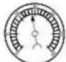
8

9

10

11

12

13

14

15
VUJ0001694
-
NORMAL READING: Needle between 51-74 kPa (15-22 in-Hg) and holding steady.1.
-
- NORMAL READING DURING RAPID ACCELERATION: When the engine is rapidly accelerated (dotted needle), the needle will drop to a low (not to zero) reading. When the throttle is suddenly released, the needle will snap back up to a higher than normal figure.
-
- NORMAL FOR HIGH-LIFT CAMSHAFT WITH LARGE OVERLAP: The needle will register as low as 51 kPa (15 in-Hg) but will be relatively steady. Some oscillation is normal.
-
- WORN RINGS OR DILUTED OIL: When the engine is accelerated (dotted needle), the needle drops to 0 kPa (0 in-Hg). Upon deceleration, the needle runs slightly above 74 kPa (22 in-Hg).
-
- STICKING VALVES: When the needle (dotted) remains steady at a normal vacuum but occasionally flicks (sharp, fast movement) down and back about 13 kPa (4 in-Hg), one or more valves may be sticking.
-
- BURNED OR BENT VALVES: A regular, evenly-spaced, downscale flicking of the needle indicates one or more burned or damaged valves. Insufficient hydraulic valve tappet or hydraulic lash adjuster clearance will also cause this reaction.
-
- POOR VALVE SEATING: A small but regular downscale flicking can mean one or more valves are not seating correctly.
-
- WORN VALVE GUIDES: When the needle oscillates over about a 13 kPa (4 in-Hg) range at idle speed, the valve guides could be worn. As engine speed increases, the needle will become steady if guides are responsible.
-
- WEAK VALVE SPRINGS: When the needle oscillation becomes more violent as engine RPM is increased, weak valve springs are
indicated. The reading at idle could be relatively steady.
-
LATE VALVE TIMING: A steady but low reading could be caused by late valve timing.10.
-
- IGNITION TIMING RETARDING: Retarded ignition timing will produce a steady but somewhat low reading.
- INSUFFICIENT SPARK PLUG GAP: When spark plugs are gapped too close, a regular, small pulsation of the needle can occur.
-
- INTAKE LEAK: A low, steady reading can be caused by an intake manifold or throttle body gasket leak.
- BLOWN HEAD GASKET: A regular drop of fair magnitude can be caused by a blown head gasket or warped cylinder head to cylinder block surface.
-
- RESTRICTED EXHAUST SYSTEM: When the engine is first started and is idled, the reading may be normal, but as the engine rpm is increased, the back pressure caused by a clogged muffler, kinked tail pipe or other concerns will cause the needle to slowly drop to 0 kPa (0 in-Hg). The needle then may slowly rise. Excessive exhaust clogging will cause the needle to drop to a low point even if the engine is only idling.
When vacuum leaks are indicated, search out and correct the cause. Excess air leaking into the system will upset the fuel mixture and cause concerns such as rough idle, missing on acceleration or burned valves. If the leak exists in an accessory such as the power brake booster, the unit will not function correctly. Always repair vacuum leaks.
Engine System - General Information - Bearing Inspection
General Procedures

natural_image
Diagram of a curved structure with arrows pointing to circular features, labeled '1' at bottom (no text or symbols on diagram itself)
flowchart
graph TD
    A["Start"] --> B["Branch 1"]
    B --> C["Branch 2"]
    C --> D["Branch 3"]
    D --> E["End"]

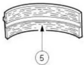
natural_image
Diagram of a curved structural element with a numbered circle and an arrow pointing upward (no text or symbols)
natural_image
Simple line drawing of a curved object with an arrow pointing to a numbered circle (no text or symbols)
natural_image
Simple line drawing of a curved mechanical component with an upward arrow and circled number 7 (no text or symbols)VUJ0002219
-
Inspect bearings for the following defects.
-
Cratering - fatigue failure
- Spot polishing - incorrect seating.
- Imbedded dirt engine oil.
- Scratching - dirty engine oil.
- Base exposed - poor lubrication.
- Both edges worn - journal damaged.
- One edge worn - journal tapered or bearing not seated.
Engine System - General Information - Camshaft Bearing Journal Clearance
General Procedures

natural_image
Technical line drawing of a mechanical assembly with no visible text or symbolsVUJ0001696

natural_image
Technical line drawing of a mechanical component with a highlighted section and arrow (no text or symbols)VUJ0001697
- NOTE: Make sure that the following stages are followed exactly. The tappets or followers must be removed to carry out this measurement.
- NOTE: Make sure that the camshaft is to specification.
- NOTE: The bearing caps and journals should be free from engine oil and dirt.
Position on a length of plastigage on the bearing cap.
- Insert the camshaft, without lubrication, into the cylinder head.
-
Position a plastigage strip, which should be equal to the width of the bearing cap, on the bearing journal.
-
Install the camshaft bearing caps. For additional information, refer to Section 303-01A EngineSection 303-01B Engine.
- NOTE: Do not strike the bearing caps.
Remove the camshaft bearing caps. For additional information, refer to Section 303-01A EngineSection 303-01B Engine.
-
Using the special tool, read off the measurement.
-
Compare the width of plastigage with the plastigage scale.
- The value that is read off is the bearing clearance.
- If the values are not to specification install a new camshaft.
Engine System - General Information - Camshaft Bearing Journal Diameter
General Procedures
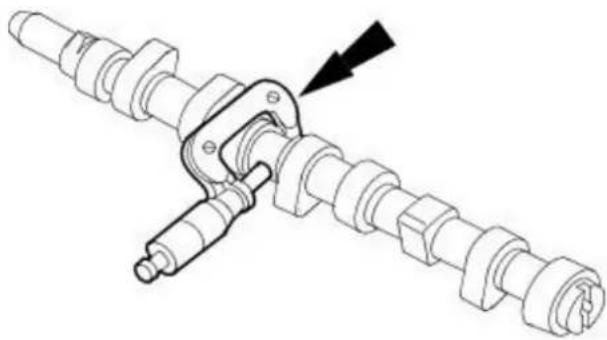
natural_image
Mechanical assembly diagram showing a crankshaft and connecting shafts with a black arrow indicating direction (no text or symbols)VUJ0001695
-
Determine the diameter of the camshaft journals.
-
Using a micrometer measure the diameter at 90 degrees intervals to determine if the journals are out-of-round.
- Measure at two different points on the journal to determine if there is any tapering.
- If the measurements are out of the specified range, install a new camshaft.
Engine System - General Information - Camshaft End Play
General Procedures

natural_image
Technical line drawing of an engine cylinder assembly with no visible text or symbols1. NOTE: Make sure that the camshaft is to specification.
Using the special tool, measure the end play.
- Slide the camshaft in both directions. Read and note the maximum and minimum values on the dial indicator gauge.
- End play = maximum value minus minimum value.
- If the measurement is out of specification, install new components.
Engine System - General Information - Camshaft Lobe Lift
General Procedures

VUJ0001699
- Measure the diameter (1) and diameter (2) with a vernier caliper. The difference in measurements is the lobe lift.
Engine System - General Information - Camshaft Surface Inspection
General Procedures

VUJ0001700
- Inspect camshaft lobes for pitting or damage in the active area. Minor pitting is acceptable outside the active area.
Engine System - General Information - Connecting Rod Cleaning
General Procedures

natural_image
Technical line drawing of an internal combustion engine piston and crankshaft (no text or labels)VUJ0002224
- CAUTION: Do not use a caustic cleaning solution or damage to connecting rods may occur.
Mark and separate the parts and clean with solvent. Clean the oil passages.
Engine System - General Information - Connecting Rod Large End Bore
General Procedures

-
Measure the bearing bore in two directions. The difference is the connecting rod bore out-of-round. Verify the out-of-round is within specification.
-
Measure the bearing bore diameter in two directions. Verify the bearing bore is within specification.
Engine System - General Information - Crankshaft End Play
General Procedures
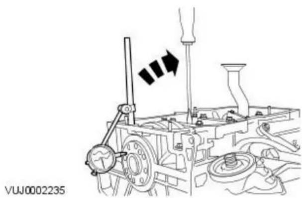
natural_image
Mechanical assembly diagram showing a valve mechanism with no visible text or symbols-
Using the Dial Indicator Gauge with Brackets, measure the end play.
-
Measure the end play by lifting the crankshaft using a lever.
- If the value is out of the specification, install new thrust half rings to take up the end float and repeat the measurement.
Engine System - General Information - Crankshaft Main Bearing Journal Clearance
General Procedures
- The main bearing machine codes are displayed on the crankshaft (1) and the cylinder block (2)
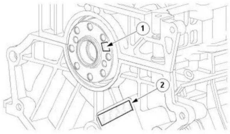
E53234

- NOTE: Main bearing number 1 relates to the front of the engine.
Read the identification numbers from the crankshaft (1).
• The first two numbers represent the code for main bearing number 1.
• The second pair of numbers represents the code for main bearing number 2.
• The third pair of numbers represents the code for main bearing number 3.
• The last pair of numbers represents the code for main bearing number 4.
E53234

- NOTE: Main bearing number 1 relates to the front of the engine.
Read the identification numbers on the cylinder block (2).
• The first two numbers represent the code for main bearing number 1.
• The second pair of numbers represents the code for main bearing number 2.
• The third pair of numbers represents the code for main bearing number 3.
- The last pair of numbers represents the code for main bearing number 4.
E53234
- Using the select fit chart, for each main bearing match the crankshaft code (1) and the block code (2) with it's corresponding column or row. By reading across the crankshaft code row (1) and down the block code column (2) select the correct grade bearing for each main.
• 1 Crankshaft code.
- 2 Block code.

- E.g. if the crankshaft code is *8580*8082* and the Block code is *0609*0711*, main bearing 1 should be assembled with a grade 1 bearing, as determined by the intersection of the number 06 block column (2) and the number 85 crankshaft row (1).
- Main bearing 2, 3 and 4 would all be assemble with a grade 2.
Engine System - General Information - Crankshaft Main Bearing Journal Diameter
General Procedures
General Equipment
Micrometer
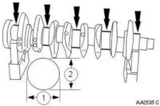
-
Measure the diameter of the main bearing journals and the big-end bearing journals.
-
Repeat the measurement with the micrometer offset by 90^ , in order to determine any eccentricity which may be present.
- Measure the journal at two different positions to determine any conicity which may be present.
Engine System - General Information - Cylinder Block Distortion
General Procedures

natural_image
Technical line drawing of a mechanical assembly with gears and shafts (no text or symbols)- Using a Straight Edge and a Feeler Gauge, measure the cylinder block/cylinder head distortion.
• Measure the mating face distortion.
- If the value is not to specification rework the mating face (if permitted).
ELE0009440
Engine System - General Information - Cylinder Bore Out-of-Round
General Procedures

VUJ0002234
- NOTE: The main bearing caps or lower crankcase must be in place and tightened to the specified torque; however, the bearing shells should not be installed.
Measure the cylinder bore with an internal micrometer.
- Carry out the measurements in different directions and at different heights to determine if there is any out-of-roundness or tapering.
- If the measurement is out of the specified range, hone out the cylinder block or install a new block.




- X-TYPE
- Sedan and Estate (Wagon)
- T9>LE OF CONTENTS
- 1: General Information
- 166: Service Information
- 166-66: General Information
- 166-61: Identification Codes
- 166-62: Jacking and Lifting
- 166-67: Noise, Vibration and Harshness
- 267: Suspension
- 267-66: Suspension System - General Information
- 267-61: Front Suspension
- 267-62: Rear Suspension
- Removal and Installation
- 267-67: Wheels and Tires
- 265: Driveline
- 265-66: Driveline System - General Information
- 265-61: Driveshaft
- 265-62: Rear Drive Axle/Differential
- 265-67: Front Drive Halfshafts
- 205-05: Rear Drive Halfshafts
- 209: Brake System
- 209-00: Brake System - General Information
- 209-03: Front Disc Brake
- 209-07: Rear Disc Brake
- 209-05: Parking Brake and Actuation
- 209-09: Hydraulic Brake Actuation
- 206-07: Power Brake Actuation
- 206-09: Anti-Lock Control - Stability Assist
- 311-63: Power Steering
- 211-63: Steering Linkage
- 211-67: Steering Column
- 211-65: Steering Column Switches
- 363: Engine
- 363-66: Engine System - General Information
- 303-01A: Engine - 2.0L NA V9 - AJV9/2.5L NA V9 - AJV9/3.0L NA V9 - AJ27
- Removal
- Disassembly
- Assembly
- Installation
- 363-61B: Engine - 2.6L Duratorq-TDCi/2.2L Duratorq-TDCi (116kW/156PS) - Puma
- In-Vehicle Repair
- 303-03A: Engine Cooling - 2.0L NA V9 - AJV9/2.5L NA V9 - AJV9/3.0L NA V9 - AJ27
- 303-03B: Engine Cooling - 2.0L Duratorq-TDCi/2.2L Duratorq-TDCi (110kW/150PS) -
- Puma
- 303-04A: Fuel Charging and Controls - 2.0L NA V9 - AJV9/2.5L NA V9 - AJV9/3.0L NA
- V9 - AJ27
- 303-04B: Fuel Charging and Controls - 2.0L Duratorq-TDCi/2.2L Duratorq-TDCi (110kW/150PS) - Puma
- 303-07C: Fuel Charging and Controls - Turbocharger
- 303-05: Accessory Drive
- 303-09: Starting System
- 303-07A: Engine Ignition - 2.0L NA V9 - AJV9/2.5L NA V9 - AJV9/3.0L NA V9 - AJ27
- 303-07B: Glow Plug System
- 303-08: Engine Emission Control - 2.0L Duratorq-TDCi/2.2L Duratorq-TDCi
- 303-12A: Intake Air Distribution and Filtering - 2.0L NA V9 - AJV9/2.5L NA V9 - AJV9/3.0L NA V9 - AJ27
- 303-14A: Electronic Engine Controls - 2.0L NA V9 - AJV9/2.5L NA V9 - AJV9/3.0L NA
- General Procedures
- 303-14B: Electronic Engine Controls - 2.0L Duratorq-TDCi/2.2L Duratorq-TDCi
- (110kW/150PS) - Puma
- 307: Automatic Transmission/Transaxle
- 307-01A: Automatic Transmission/Transaxle - Vehicles With: 5-Speed Automatic Transaxle - JATCO
- 307-01B: Automatic Transmission/Transaxle - Vehicles With: 9-Speed Automatic
- Transaxle - AWF21
- 307-02A: Transmission/Transaxle Cooling - Vehicles With: 5-Speed Automatic
- Transaxle - JATCO
- 307-02B: Transmission/Transaxle Cooling - Vehicles With: 9-Speed Automatic
- 307-05A: Automatic Transmission/Transaxle External Controls - Vehicles With:
- 307-05B: Automatic Transmission/Transaxle External Controls - Vehicles With:
- 308: Manual Transmission/Transaxle, Clutch and Transfer Case
- 308-00: Manual Transmission/Transaxle and Clutch - General Information
- 308-01: Clutch
- 308-02: Clutch Controls
- 308-03: Manual Transmission/Transaxle
- 308-09: Manual Transmission/Transaxle External Controls
- 308-07: Transfer Case
- 309-00: Exhaust System
- 310: Fuel System
- 310-00: Fuel System - General Information
- 316-61: Fuel Tank and Lines
- 316-62: Acceleration Control
- 316-63: Speed Control
- 7: Electrical
- 712: Climate Control System
- 712-66: Climate Control System - General Information
- 712-61: Air Distribution and Filtering
- 712-62A: Heating and Ventilation
- 712-62B: Auxiliary Heating
- 712-63: Air Conditioning
- 712-67: Control Components
- 413: Instrumentation and Warning Systems
- 413-00: Instrument Cluster and Panel Illumination
- 413-01: Instrument Cluster
- 413-09: Horn
- 413-08: Information and Message Center
- 413-09: Warning Devices
- 413-13: Parking Aid
- 414: Battery and Charging System
- 414-00: Battery and Charging System - General Information
- 715-66: Information and Entertainment System - General Information
- 715-61: Audio Unit
- 715-62: Antenna
- 715-63: Speakers
- 417: Lighting
- 417-01: Exterior Lighting
- 417-02: Interior Lighting
- 417-04: Daytime Running Lamps (DRL)
- 418: Electrical Distribution
- 418-00: Module Communications Network
- 418-01: Module Configuration
- 418-02: Wiring Harnesses
- 419: Electronic Feature Group
- 419-01A: Anti-Theft - Active
- 419-01B: Anti-Theft - Passive
- 419-02: Remote Convenience
- 419-07: Navigation System
- 419-08: Cellular Phone
- 419-10: Multifunction Electronic Modules
- 5: Body and Paint
- 501: Body and Paint
- 501-02: Front End Body Panels
- 501-03: Body Closures
- 501-05: Interior Trim and Ornamentation
- 501-08: Exterior Trim and Ornamentation
- 501-09: Rear View Mirrors
- 501-10: Seating
- 561-11: Glass, Frames and Mechanisms
- 561-12: Instrument Panel and Console
- 561-17: Handles, Locks, Latches and Entry Systems
- 501-19: Wipers and Washers
- 501-17: Roof Opening Panel
- 501-19: Bumpers
- 501-20A: Safety Belt System
- 501-20B: Supplemental Restraint System
- 562: Frame and Mounting
- 562-66: Uni-Body, Subframe and Mounting System
- Description and Operation
- General Information - About This Manual
- Notes, Cautions and Warnings
- General Information - Application and Use of Specifications
- Torque Specifications
- General Information - General Service Information
- Repairs and Replacements
- Vehicle Specifications
- Service Repair Operation Numbering
- References to Bank-1 and Bank-2
- Special Tools
- Disconnecting/ Connecting the Battery
- Reconnecting the Battery
- Connecting a Slave Battery Using Jump Leads
- Component Cleaning
- Cleaning Methods:
- Calibration of Essential Measuring Equipment
- Use of Control Modules
- Functional Test
- Preparation
- Dismantling
- Inspection
- On-Board Diagnostics (OBD)
- Circuit Diagrams
- Glossary of Terms
- General Information - Health and Safety Precautions
- Acids and Alkalis
- Air Bags
- Air Conditioning Refrigerant
- Air Conditioning Refrigerant - Do Nots
- Antifreeze
- Asbestos
- Battery Acids
- Brake and Clutch Linings and Pads
- Brakes Fluids (Polyalkylene Glycols)
- Brazing
- Chemical Materials
- Chemical Materials - Do's
- Chemical Materials - Do Nots
- Chlorofluorocarbons (CFC)
- Clutch Fluids
- Clutch Linings and Pads
- Corrosion Protection Materials
- Cutting
- Dewaxing
- Dusts
- Electric Shock
- Engine Oils
- Exhaust Fumes
- Gasolene (petrol) engine
- Fibre Insulation
- Fire
- First Aid
- Fluoroelastomer
- Foams - Polyurethane
- Freon
- Fuels
- Gasoline (Petrol)
- Gas - oil (Diesel Fuel)
- Kerosene (Paraffin)
- Gas Cylinders
- Gases
- Gaskets (Fluoroelastomer)
- General Workshop Tools and Equipment
- High Pressure Air, Lubrication and Oil Test Equipment
- Halon
- Legal Aspects
- Lubricants and Greases
- Used Engine Oil
- Health Protection Precautions
- Environmental Precautions
- Noise
- Noise Insulation Materials
- 0-Rings (Fluoroelastomer)
- Paints
- Pressurized Equipment
- Solder
- Solvents
- Sound Insulation
- Suspended Loads
- Transmission Brake Bands
- Underseal
- Viton
- Welding
- Resistance Welding
- Arc Welding
- Gas Welding (and Cutting)
- Warning Symbols on Vehicles
- White Spirit
- Safety Precautions
- Environmental Protection
- General Information - How To Use This Manual
- Copyright Statement
- Workshop Manual Organization
- General Information - Important Safety Instructions
- General Information - Road/ Roller Testing
- Pre - Test Checks
- Starting the Engine
- On Road or Roller Test Check:
- Brake Testing
- General Information - Solvents, Sealants and Adhesives
- Adhesives and Sealers
- Solvent - based Adhesives/ Sealers - See Solvents
- Water - based Adhesives/ Sealers
- Hot Melt Adhesives
- Resin - based Adhesives/ Sealers e.g. Epoxide and Formaldehyde Resin - based
- Anaerobic, Cyanoacrylate (Super - glues) and other Acrylic Adhesives
- Isocyanate (Polyurethane) Adhesives/ Sealers
- General Information - Standard Workshop Practices
- Protecting the Vehicle
- Vehicle in Workshop
- Identification Codes - Identification Codes
- Vehicle Identification Number (VIN)
- Vehicle Identification Number (Example)
- World Manufacturer Identifier
- Market, Air Bag Specification
- Transmission, Steering Code
- Body Code
- Engine Emission System
- VIN Position 8
- Check Digit
- Model Year
- Assembly Plant and Model Line
- Production Sequence Number
- Vehicle Certification Label
- Automatic Transmission Number
- Manual Transmission Number
- Engine Number (V6)
- Engine Number (Diesel)
- Jacking and Lifting - Lifting
- Lifting Points—Twin-Post Hoist and Floor Jack
- Vehicle Support Points
- Vehicle Recovery
- Front Suspended Tow
- Emergency Towing-Vehicles fitted with manual transmission:
- Emergency Towing-Vehicles fitted with automatic transmission:
- Noise, Vibration and Harshness - Noise, Vibration and Harshness (NVH)
- Diagnostic Theory
- Know the System
- Know the History of the System
- Know the History of the Condition
- Know the Probability of Certain Conditions Developing
- Do Not Cure the Symptom and Leave the Cause
- Be Positive the Cause is Found
- Diagnostic Charts
- Inspection and Verification
- How To Use This Diagnostic Procedure Section
- Customer Interview
- Identify the Condition
- Noise Diagnostic Procedure
- Non-Axle Noise
- Noise Conditions
- Vibration Conditions
- Leakage Conditions
- Inoperative Conditions
- Road Test
- Road Test Quick Checks
- Road Conditions
- Vehicle Preparation
- Lift Test
- Pinpoint Tests
- Noise, Vibration and Harshness - Exhaust System Neutralizing
- Suspension System - General Information -
- Suspension System - General Information - Wheel Alignment Angles
- Toe
- Ride Height
- Wheel Track
- Crabbing
- Wander
- Shimmy
- Nibble
- Poor Returnability of the Steering
- Drift/ Pull
- Vague On-Center Feel
- Suspension System - General Information - Suspension System
- Component Tests
- Ball Joint Inspection
- Suspension System - General Information - Front Toe Adjustment
- Suspension System - General Information - Rear Toe Adjustment
- Suspension System - General Information - Wheel Bearing Inspection
- Front Suspension - Front Suspension
- Strut and Spring Assembly
- Front Suspension - Lower Arm
- Front Suspension - Shock Absorber and Spring Assembly
- Vehicles with high intensity discharge headlamps
- Front Suspension - Front Stabilizer Bar
- Front Suspension - Front Stabilizer Bar Bushing
- Vehicles with diesel engine
- All vehicles
- Front Suspension - Front Wheel Bearing and Wheel Hub
- Front Suspension - Wheel Knuckle
- Rear Suspension - Rear Suspension
- Components
- Bushings:
- Rear Suspension - Front Lower Arm4-Door
- Rear Suspension - Front Lower Arm Wagon
- Rear Suspension - Rear Stabilizer Bar
- Rear Suspension - Rear Stabilizer Bar Link
- Rear Suspension - Wheel Hub
- Vehicles with 2.0L engine
- Vehicles with 2.5L or 3.0L engine
- Rear Suspension - Wheel Knuckle Front Bushing
- Rear Suspension - Wheel Knuckle Rear Bushing
- Wheels and Tires - Safety Precautions
- Locking Wheel Nuts
- Recommended Tires
- Tire Inflation Pressures
- Tire Replacement and Wheel-Interchanging
- Vehicles fitted with Tire Pressure Monitoring System
- Winter (Snow) Tires
- Rotational Indicators
- Temporary-Use Spare Wheel
- Tread Wear Indicator
- Tire Pressure Monitoring System
- Tire Location and Identification
- Initiator
- E45552
- Tire Pressure Sensor
- E45553
- Instrument Cluster
- Principles of Operation
- Wheels and Tires - Wheels and Tires
- General notes
- Tire Wear Inspection
- Tire Wear Diagnosis
- Torque Sensitive
- Vehicle Speed Sensitive
- Engine Speed Sensitive
- Wheels and Tires - Tire Low Pressure SensorVIN Range: J28493->V99999
- Wheels and Tires - Tire Pressure Monitoring System (TPMS) Front AntennaVIN Range: J28493->V99999
- Wheels and Tires - Tire Pressure Monitoring System (TPMS) Main AntennaVIN Range: J28493->V99999
- Wheels and Tires - Tire Pressure Monitoring System (TPMS) ModuleVIN Range: J28493->V99999
- Wheels and Tires - Tire Pressure Monitoring System (TPMS) Rear AntennaVIN Range: J28493->V99999
- Vehicles with aluminium wheels
- Driveline System - General Information - Driveline System
- Driveline Vibration
- Driveline Angle
- Transfer Case, Front Transaxle and Axle Noise
- Gear Howl and Whine
- Bearing Whine
- Knock
- Clunk
- Bearing Rumble
- Symptom Chart
- Universal Joint
- Rear Drive Axle/ Differential -
- Rear Drive Axle/ Differential - Rear Drive Axle and Differential
- Rear Drive Axle/ Differential - Axle Shaft Seal
- Rear Drive Axle/ Differential - Drive Pinion Flange
- Rear Drive Axle/ Differential - Drive Pinion Seal
- Front Drive Halfshafts - Front Drive Halfshafts
- Front Drive Halfshafts
- Handling Front Drive Halfshafts
- Underbody Protection and Corrosion Prevention
- Front Drive Halfshafts - Front Halfshaft LH
- Vehicle with automatic transmission
- Vehicles with manual transmission
- Front Drive Halfshafts - Front Halfshaft RH2.0L NA V6 - AJV6/ 2.5L NA V6 - AJV6/ 3.0L NA V6 - AJ27
- Front Drive Halfshafts - Front Halfshaft RH2.0L Duratorq-TDCi/ 2.2L Duratorq-TDCi (110kW/ 150PS) - Puma
- Front Drive Halfshafts - Inner Constant Velocity (CV) Joint Boot
- Front Drive Halfshafts - Intermediate Shaft
- Vehicles with automatic transmission
- Front Drive Halfshafts - Outer Constant Velocity (CV) Joint Boot
- Rear Drive Halfshafts -
- Rear Drive Halfshafts - Rear Drive Halfshafts
- Handling Rear Drive Halfshafts
- Rear Drive Halfshafts - Rear Halfshaft
- Rear Drive Halfshafts - Outer Constant Velocity (CV) Joint Boot
- Brake System - General Information -
- Brake System - General Information - Brake System
- Brake Booster
- Brake Master Cylinder
- Normal Conditions
- Abnormal Conditions
- Non Pressure Leaks
- Check
- Brake System - General Information - Brake System Bleeding
- Front Disc Brake - Front Disc Brake
- Front Disc Brake - Brake Caliper
- CAUTIONS:
- Rear Disc Brake - Rear Disc Brake
- Rear Disc Brake - Brake Caliper
- CAUTIONS:
- Rear Disc Brake - Brake Pads
- Parking Brake and Actuation -
- Item Part Number Description
- Parking Brake and Actuation - Parking Brake
- Yes
- No
- B4: CHECK REAR PARKING BRAKE CABLES
- Parking Brake and Actuation - Parking Brake Cable Vehicles With: Manually Adjusted Parking Brake
- Parking Brake and Actuation - Parking Brake Cable Vehicles With: Self-Adjusting Parking Brake
- Parking Brake and Actuation - Parking Brake Control Vehicles With: Manually Adjusted Parking Brake
- Parking Brake and Actuation - Parking Brake Control Vehicles With: Self-Adjusting Parking Brake
- Hydraulic Brake Actuation -
- Hydraulic Brake Actuation - Hydraulic Brake Actuation
- Hydraulic Brake Actuation - Brake Fluid Reservoir
- Hydraulic Brake Actuation - Brake Master Cylinder
- Hydraulic Brake Actuation - Brake Pedal and Bracket
- Right-hand drive vehicles
- Vehicles without driver lower air bag
- Vehicles with driver lower air bag
- Left-hand drive vehicles
- Hydraulic Brake Actuation - Brake Pedal Cross-Shaft
- All except vehicles with diesel engine
- Power Brake Actuation - Brake Booster
- Power Brake Actuation - Power Brake System
- Power Brake Actuation - Brake BoosterLHD AWD/ LHD FWD
- Power Brake Actuation - Brake BoosterRHD AWD/ RHD FWD
- Power Brake Actuation - Brake Vacuum Pump2.0L NA V6 - AJV6
- Power Brake Actuation - Brake Vacuum Pump2.0L Duratorq-TDCi/ 2.2L Duratorq-TDCi (110kW/ 150PS) - Puma
- Anti-Lock Control - Stability Assist -
- Anti-Lock Control - Stability Assist - Anti-Lock Control - Stability Assist
- Anti-Lock Control - Stability Assist - Anti-Lock Control - Stability AssistVIN Range: C00344->J12991
- Principle of operation
- Diagnostic Drive Cycles
- Anti-Lock Control - Stability Assist - Anti-Lock Control - Stability Assist V1N Range: J12992->V99999
- DTC index
- Anti-Lock Control - Stability Assist - Anti-Lock Brake System (ABS) ModuleVIN Range: C00001->J12991
- Anti-Lock Control - Stability Assist - Front Wheel Speed Sensor
- Anti-Lock Control - Stability Assist - Hydraulic Control Unit (HCU) VIN Range: C00001->J12991
- Anti-Lock Control - Stability Assist - Hydraulic Control Unit (HCU) VIN Range: J12992-> V99999
- Anti-Lock Control - Stability Assist - Rear Wheel Speed Sensor
- Anti-Lock Control - Stability Assist - Stability Assist Module
- Anti-Lock Control - Stability Assist - Steering Wheel Rotation Sensor
- Anti-Lock Control - Stability Assist - Yaw Rate Sensor2.0L Duratorq-TDCi/ 2.0L NA V6 - AJV6/ 2.5L NA V6 - AJV6/ 3.0L NA V6 - AJ27
- Anti-Lock Control - Stability Assist - Yaw Rate Sensor2.2L Duratorq-TDCi (110kW/ 150PS) - Puma
- Steering System - General Information -
- Steering System - General Information - Steering System
- Steering Relay Harness Connector
- Steering Linkage Inspection and Backlash (Freeplay) Check
- Power Steering Fluid Condition Check
- Power Steering Pressure Test
- Installing Test Equipment
- Removing Test Equipment
- Steering Fault Diagnosis by Symptom Charts
- Description of General Steering System Noises
- Boom
- Buzz
- Chatter
- Chuckle
- Chirp
- Click
- Click/ Thump
- Grind
- Groan/ Moan
- Groan/ Howl
- Hiss
- Hum
- Ping
- Rattle
- Roar
- Rumble
- Scrape
- Squeak
- Squeal
- Tap
- Weep
- Whir/ Whine
- Whistle
- Description of Specific Steering System Noise Types
- Belt Squeal
- Clonk
- Column Knock
- Column Rattle
- Grinding/ Scrape
- Grunt (Squawk)
- Hiss (Swish)
- Moan (Groan)
- Rack Knock (Rack Slap)
- Rattles
- Squeaks/ Scrapes
- Zip
- Steering System Vibrations and Harshness
- Buzz (Electrical)
- Column/ Steering Wheel Shake
- Nibble (Shimmy)
- Shudder (Judder)
- Torque Ripple
- Torque/ Velocity Variation (Phasing/ Effort Cycling)
- Wheel Fight (Kick Back)
- Steering Linkage
- Steering System - General Information - Power Steering System Filling
- Steering System - General Information - Power Steering System Flushing
- Power Steering - Start Up Procedure After Power Steering Pump/ Gear Overhaul
- Power Steering - Power Steering Control Valve Actuator2.5L NA V6 - AJV6/ 3.0L NA V6 - AJ27
- Power Steering - Power Steering Fluid Cooler2.0L Duratorq-TDCi
- Power Steering - Power Steering Fluid Cooler2.2L Duratorq-TDCi (110kW/150PS) - Puma
- Power Steering - Power Steering Fluid Reservoir
- Power Steering - Power Steering Pump2.0L NA V6 - AJV6/ 2.5L NA V6 - AJV6/ 3.0L NA V6 - AJ27
- Power Steering - Power Steering Pump2.0L Duratorq-TDCi/ 2.2L Duratorq-TDCi (110kW/ 150PS) - Puma
- Power Steering - Steering Gear2.0L Duratorq-TDCi/ 2.2L Duratorq-TDCi (110kW/ 150PS) - Puma
- Power Steering - Steering Gear2.0L NA V6 - AJV6/ 2.5L NA V6 - AJV6/ 3.0L NA V6 - AJ27
- Steering Linkage - Steering Linkage
- Steering Linkage - Tie Rod End
- Steering Column - Steering Column
- Steering Column - Ignition Switch Lock Cylinder
- Steering Column - Steering Column Coupling
- Steering Column Switches - Steering Column Switches
- Steering Column Multifunction Switch RH
- Flick Wipe
- Intermittent Wipe
- Slow Speed Wiper
- High Speed Wiper
- Windscreen Wash/ Wipe
- Headlamp Power Wash (if equipped)
- Rain Sensing/ Auto Wipe (if equipped)
- Steering Column Multifunction Switch LH
- Direction Indicators
- Main Beam
- Steering Column Switches - Steering Column Multifunction Switch LH
- Steering Column Switches - Steering Column Multifunction Switch RH
- Engine System - General Information -
- Engine System - General Information - Engine
- 2.0L, 2.5L and 3.0L Engines
- 2.0L and 2.2L common rail diesel engine
- Engine Oil Leaks
- Fluorescent Oil Additive Method
- Compression Test
- General Remarks
- Check The Compression Pressure
- Interpretation of the Results
- Excessive Engine Oil Consumption
- Oil Consumption Test
- Intake Manifold Vacuum Test
- Interpreting Vacuum Gauge Readings
- VUJ0001694
- Engine System - General Information - Bearing Inspection
- Engine System - General Information - Camshaft Bearing Journal Clearance
- Engine System - General Information - Camshaft Bearing Journal Diameter
- Engine System - General Information - Camshaft End Play
- NOTE: Make sure that the camshaft is to specification.
- Engine System - General Information - Camshaft Lobe Lift
- Engine System - General Information - Camshaft Surface Inspection
- Engine System - General Information - Connecting Rod Cleaning
- Engine System - General Information - Connecting Rod Large End Bore
- Engine System - General Information - Crankshaft End Play
- Engine System - General Information - Crankshaft Main Bearing Journal Clearance
- Engine System - General Information - Crankshaft Main Bearing Journal Diameter
- General Equipment
- Engine System - General Information - Cylinder Block Distortion
- Engine System - General Information - Cylinder Bore Out-of-Round
Brand : JAGUAR
Model : X-Type (2001)
Category : Car