
BUB360Z - Blower MAKITA - Free user manual and instructions
Find the device manual for free BUB360Z MAKITA in PDF.


| Brand | Makita |
| Model | BUB360Z |
| Product type | Cordless blower |
| Overall length (without nozzle) | 424 mm |
| Overall length (with long nozzle) | 921 mm |
| Net weight (with battery) | 3.1 kg |
| Power supply | 36 V DC lithium-ion battery (not included) |
| No load speed (HIGH) | 17,000 min⁻¹ |
| No load speed (LOW) | 10,000 min⁻¹ |
| Air flow (HIGH) | 4.4 m³/min |
| Air flow (LOW) | 2.6 m³/min |
| Sound pressure level | 81.2 dB(A) |
| Guaranteed sound power level | 96.0 dB(A) |
| Vibration (no load) | 2.5 m/s² or less |
| Main functions | Blowing dust and debris, two speeds, battery protection shut-off |
| Maintenance and cleaning | Clean the tool with a damp cloth and mild soap; replace brushes when worn |
| Safety | Wear safety glasses and hearing protection; do not point the nozzle at people; do not expose to rain |
| Spare parts and repairability | Contact an authorized Makita service center; use only Makita parts |
| Included accessories | Long nozzle, shoulder strap |
| General information | Complies with European directives 2000/14/EC and 2006/42/EC; standard EN15503 |
Frequently Asked Questions - BUB360Z MAKITA
User questions about BUB360Z MAKITA
0 question about this device. Answer the ones you know or ask your own.
Ask a new question about this device
Download the instructions for your Blower in PDF format for free! Find your manual BUB360Z - MAKITA and take your electronic device back in hand. On this page are published all the documents necessary for the use of your device. BUB360Z by MAKITA.
USER MANUAL BUB360Z MAKITA
GB Cordless Blower Instruction Manual
F SOUFFLEUR SANS FIL Manuel d'instructions
natural_image
Line drawing of a handheld electric shaver tool (no text or symbols)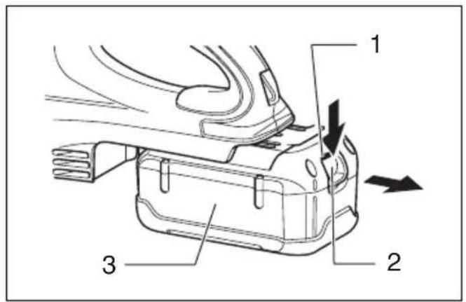
1

2

3
4

5

natural_image
Line drawing of a person using a long-handled tool (no text or symbols present)6
natural_image
Line drawing of a hand gripping a handheld device (no text or symbols)
natural_image
Pure mechanical diagram showing a spring-loaded component with a 10-unit dimension label (no text or symbols beyond the label)7

8
9
END102-3
Symbols
The followings show the symbols used for the equipment. Be sure that you understand their meaning before use.
Symboles
- Keep bystanders away.
- Wear eye and ear protection.
- Do not expose to moisture.
- Only for EU countries
Do not dispose of electric equipment or battery pack together with household waste material! In observance of European Directive 2002/96/EC on waste electric and electronic equipment, 2006/66/EC on batteries and accumulators and waste batteries and accumulators and their implementation in accordance with national laws, electric equipment and battery pack that have reached the end of their life must be collected separately and returned to an environmentally compatible recycling facility.
Explanation of general view
| 1 | R | e | d | p | a | r | t | 5 | “ | O | F | F | ” | b | u | 9 | tH | oa | nn | g | e | r | ||
| 2 | B | u | t | t | o | n | 6 | H | o | o | k | 10 | Limit | mark | ||||||||||
| 3 | Battery | cartridge | 7 | B | u | t | t | o | n | 11 | Screwdriver | |||||||||||||
| 4 | H | I | G | H | / | L | O | W | 8 | Lb | ou | nt | g | o | m | o | z | 12 | Bitusheholder | cap |
ENB116-4
SPECIFICATIONS
Model BUB360
Capacities
Air volume (HIGH) 4.4 m³/min.
Air volume (LOW) 2.6 m³/min.
No load speed (min -1 )
HIGH.... 17,000
LOW.... 10,000
Overall length
(without long nozzle).... 424 mm
(with long nozzle).... 921 mm
Net weight.... 3,1 kg
Rated voltage D.C. 36 V
- Due to our continuing program opment, the specifications herein are subject to change without notice.
- Specifications may differ from
- Weight according to EPTA - Proc
Intended use
The tool is intended for blowing dust.
GEA010-1
General Power Tool Safety Warnings
⚠ WARNING Read all safety warnings and all instructions. Failure to follow the warnings and instructions may result in electric shock, fire and/or serious injury.
Save all warnings and instructions for future reference.
BLOWER SAFETY WARNINGS
- Always use protective goggles, a cap and mask when using the blower.
- Never point the nozzle at anyone in the vicinity when using the blower.
- Warning – Electric shock could occur if used on wet surfaces. Do not expose to rain. Store indoors.
-
Never block suction inlet and/or blower outlet.
-
Do not block suction inlet or blower outlet to clean up in dusty areas.
- Do not use the blower with a tapered nozzle
o f smaller than the original one, such as a new nozzle obtained by attaching an extra diameter-reduced hose or smaller hose to the nozzle c top end y to country.
Do not use/the flower to inflate balls rubber boat or the similar.
Increased motor revolution may cause dangerous fan breakage and result in serious personal injury.
Heated motor and control circuit may cause a fire.
- Keep children, other bystanders and pets away from the blower while operating.
- Do not operate the blower near open window, etc.
- Operating the blower only at reasonable hours is recommended – not early in the morning or late at night when people might be disturbed.
- Using rakes and brooms to loosen debris before blowing is recommended.
- It is recommended to slightly dampen surfaces in dusty conditions or use mister attachment available on the market.
- It is recommended to use the long nozzle so the air stream can work close to the ground.
- The blower is not intended for use by young children or infirm persons without supervision.
- Young children should be supervised to ensure that they do not play with the blower.
SAVE THESE INSTRUCTIONS.
WARNING:
DO NOT let comfort or familiarity with product (gained from repeated use) replace strict adherence to safety rules for the subject product. MISUSE or failure to follow the safety rules stated in this instruction manual may cause serious personal injury.
IMPORTANT SAFETY INSTRUCTIONS
FOR BATTERY CARTRIDGE
- Before using battery cartridge, read all instructions and cautionary markings on (1) battery charger, (2) battery, and (3) product using battery.
- Do not disassemble battery cartridge.
- If operating time has become excessively shorter, stop operating immediately. It may result in a risk of overheating, possible burns and even an explosion.
- If electrolyte gets into your eyes, rinse them out with clear water and seek medical attention right away. It may result in loss of your eyesight.
- Do not short the battery cartridge:
(1) Do not touch the terminals with any conductive material.
(2) Avoid storing battery cartridge in a container with other metal objects such as nails, coins, etc.
(3) Do not expose battery cartridge to water or rain.
A battery short can cause a large current flow, overheating, possible burns and even a breakdown.
- Do not store the tool and battery cartridge in locations where the temperature may reach or exceed 50irc C ( 122irc F).
- Do not incinerate the battery cartridge even if it is severely damaged or is completely worn out. The battery cartridge can explode in a fire.
- Be careful not to drop or strike battery.
- Do not use a damaged battery.
SAVE THESE INSTRUCTIONS.
Tips for maintaining maximum battery life
- Charge the battery cartridge before completely discharged. Always stop tool operation and charge the battery cartridge when you notice less tool power.
- Never recharge a fully charged battery cartridge. Overcharging shortens the battery service life.
- Charge the battery cartridge with room temperature at 10irc C – 40irc C ( 50irc F – 104irc F). Let a hot battery cartridge cool down before charging it.
FUNCTIONAL DESCRIPTION
CAUTION:
- Always be sure that the tool is switched off and the battery cartridge is removed before adjusting or checking function on the tool.
Installing or removing battery cartridge (Fig. 1)
- Always switch off the tool before the battery cartridge.
- To remove the battery cartridge, withdraw it from the tool while sliding the button on the front of the cartridge.
- To insert the battery cartridge, align the tongue on the battery cartridge with the groove in the housing and slip it into place. Always insert it all the way until it locks in place with a little click. If you can see the red part on the upper side of the button, it is not locked completely. Insert it fully until the red part cannot be seen. If not, it may accidentally fall out of the tool, causing injury to you or someone around you.
- Do not use force when inserting the battery cartridge. If the cartridge does not slide in easily, it is not being inserted correctly.
Battery protection system
The battery cartridge is equipped with the protection system, which automatically cuts off the output power for its long service life.
The tool may stop during operation when the tool and/or battery are placed under the following situation. This is caused by the activation of protection system and does not show the tool trouble.
- When the tool is overloaded:
At this time, press the "OFF" button and remove causes of overload and then press the "HIGH/LOW" button again to restart. When the tool does not work even after pressing the "HIGH/LOW" button, the battery power auto-stop is still at work. Charge the battery cartridge before use. - When the remaining battery capacity becomes low: Recharge the battery cartridge.
Switch action (Fig. 2)
To start the tool, simply press the "HIGH/LOW" button. To switch off, press the "OFF" button. To change the tool speed, press the "HIGH/LOW" button. The first press on this button is for high speed and the second press for low speed and then each press on this button repeats the high/low speed cycle alternatively.
ASSEMBLY
CAUTION:
- Always be sure that the tool is switched off and the battery cartridge is removed before carrying out any work on the tool.
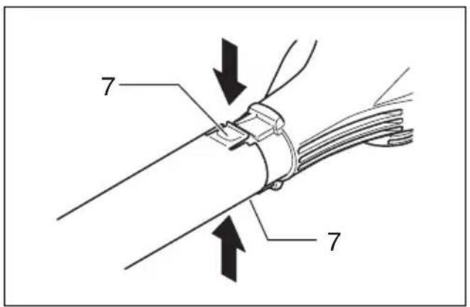
Installing or removing the long nozzle (Fig. 3 & 4)
To install the long nozzle, push in onto the blower outlet of the tool all the way.
To remove the long nozzle, press its both buttons and with the buttons being pressed pull it out.
Installing the shoulder strap (Fig. 5)
Pull the hanger out of the tool.
Hook the shoulder strap onto the hanger of the tool.
Before use, adjust the length of strap so that it is easy to work with it.
OPERATION
Blowing (Fig. 6)
Hold the blower firmly with a hand and perform the blowing operation by moving it around slowly.
When blowing around a building, a big stone or a vehicle, direct the nozzle away from them.
When performing an operation in corner, start from the corner and then move to wide area.
MAINTENANCE
CAUTION:
- Always be sure that the tool is switched off and the battery cartridge is removed before attempting to perform inspection or maintenance.
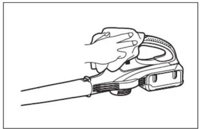
Cleaning (Fig. 7)
From time to time, wipe off the outside of the tool using a cloth dampened in soapy water.
CAUTION:
- Never use gasoline, benzine, thinner, alcohol or the like. Discoloration, deformation or cracks may result.
Replacing carbon brushes (Fig. 8 & 9)
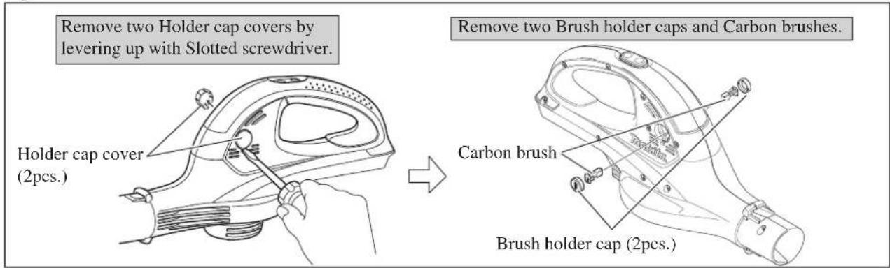
Remove and check the carbon brushes regularly. Replace when they wear down to the limit mark. Keep the carbon brushes clean and free to slip in the holders. Both carbon brushes should be replaced at the same time. Use only identical carbon brushes.
Use a screwdriver to remove the brush holder caps.
Take out the worn carbon brushes, insert the new ones and secure the brush holder caps.
To maintain product SAFETY and RELIABILITY, repairs, any other maintenance or adjustment should be performed by Makita Authorized Service Centers, always using Makita replacement parts.
ACCESSORIES
CAUTION:
- These accessories or attachments are recommended for use with your Makita tool specified in this manual. The use of any other accessories or attachments might present a risk of injury to persons. Only use accessory or attachment for its stated purpose.
If you need any assistance for more details regarding these accessories, ask your local Makita service center.
- Long nozzle
- Shoulder strap
- Various type of Makita genuine batteries and chargers
- Battery adaptor
Descriptif
| 1 | P | a | r | t | i | e | r | o | 5 | u | B | g | o | e | u | t | o | n | d | 9 | a | C | r | r | ro | ê | c | t | h | e“ | t | O | Fp | Fo | ” |
| 2 | B | o | u | t | o | n | 6 | C | r | o | c | h | e | t | |||||||||||||||||||||
| 3 | B | a | t | t | e | r | i | e | 7 | B | o | u | t | o | n | ||||||||||||||||||||
| 4 | B | o | u | t | o | n | H | 8 | G | b | l | n | g | O | e | V |
SPÉCIFICATIONS
Modèle BUB360
Capacités
Volume d'air élevé (HIGH) .... 4,4 m 3/min.
Volume d'air bas (LOW) 2,6 m 3/min.
For European countries only
EC Declaration of Conformity
We Makita Corporation as the responsible manufacturer declare that the following Makita machine(s):
Designation of Machine: Cordless Blower
Model No./ Type: BUB360
Specifications: see "SPECIFICATIONS" table.
are of series production and
Conforms to the following European Directives: 2000/14/EC, 2006/42/EC
And are manufactured in accordance with the following standards or standardised documents:
EN15503
The technical documentation is kept by our authorized representative in Europe who is:
Makita International Europe Ltd,
Michigan, Drive, Tongwell,
Milton Keynes, MK15 8JD, England
The conformity assessment procedure required by
Directive 2000/14/EC was in Accordance with annex V.
Measured Sound Power Level: 92.4 dB
Guaranteed Sound Power Level: 96.0 dB
FRANÇAIS
Michigan, Drive, Tongwell,
Milton Keynes, MK15 8JD, Angleterre
Tomoyasu Kato Director
Makita Corporation
3-11-8, Sumiyoshi-cho,
Anjo, Aichi, JAPAN
12.11.2009
3-11-8, Sumiyoshi-cho,
Anjo, Aichi, JAPAN
DEUTSCH ITALIANO
Michigan, Drive, Tongwell,
Milton Keynes, MK15 8JD, England
Michigan, Drive, Tongwell,
Milton Keynes, MK15 8JD, England
Makita International Europe Ltd., Michigan, Drive, Tongwell,
Milton Keynes, MK15 8JD, Engeland
Makita International Europe Ltd, Michigan, Drive, Tongwell,
Milton Keynes, MK15 8JD, Inglaterra
Tomoyasu Kato Director
Makita Corporation
3-11-8, Sumiyoshi-cho, Anjo, Aichi, JAPAN
PORTUGUÊS DANSK
2000/14/EC, 2006/42/EC
Michigan, Drive, Tongwell,
Milton Keynes, MK15 8JD, Inglaterra
Michigan, Drive, Tongwell,
Milton Keynes, MK15 8JD, England
3-11-8, Sumiyoshi-cho,
Anjo, Aichi, JAPAN
12.11.2009
Tomoyasu Kato
Direktør
Makita Corporation
3-11-8, Sumiyoshi-cho,
Anjo, Aichi, JAPAN
ΕΛΛΗΝΙΚΑ
2000/14/EK, 2006/42/EK
Michigan, Drive, Tongwell,
Milton Keynes, MK15 8JD, England (Aγγλία)
3-11-8, Sumiyoshi-cho,
Anjo, Aichi, JAPAN
ENGLISH
ENG102-3
Noise
The typical A-weighted noise level determined according to EN15503:
Sound pressure level ( LpA ): 81.2 dB (A)
Sound power level ( LWA ): 93.9 dB (A)
Uncertainty (K): 2.5 dB (A)
Wear ear protection
ENG900-1
Vibration
The vibration total value (tri-axial vector sum) determined according to EN15503:
Work mode: operation without load
Vibration emission (ah): 2.5 m/s 2 or less
Uncertainty (K): 1.5 m/s
ENG901-1
- The declared vibration emis sured in accordance with the standard test method and may be used for comparing one tool with another.
- The declared vibration emission value may also be used in a preliminary assessment of exposure.
WARNING:
- The vibration emission during tool can differ from the declared emission value depending on the ways in which the tool is used.
- Be sure to identify safety measures to protect the operator that are based on an estimation of exposure in the actual conditions of use (taking account of all parts of the operating cycle such as the times when the tool is switched off and when it is running idle in addition to the trigger time).
FRANÇAIS
ENG102-3
Bruit
Description ▶ Cordless Blower 36V
CONCEPT AND MAIN APPLICATIONS
Model BUB360 is a cordless blower powered by 36V/2.6Ah Li-ion battery BL3626. This model will be one of the best choice for use especially in public spaces or among residential areas instead of gas-powered blowers.
Features High/ Low push button for two different air volume settings.
This product is available with the following model number and specifications.
| Model No. | Charger | Battery cover | Battery | |
| BUB360Z | No No | No |
The model also includes the accessory listed below in "Standard equipment".

| Dimensions: mm (") | |
| Length (L1) | 921 (36-1/4) |
| Length (L2) | 436 (17-1/8) |
| Width (W) | 142 (5-5/8) |
| Height (H) | 204 (8) |
*L1: Length with Long nozzle
*L2: Length with without Long nozzle
Specification
| Model No. | BUB360 | ||
| Battery | Voltage: V | 36 | |
| Capacity: Ah | 2.6 | ||
| Cell | Li-ion | ||
| Charging time (approx.): min. | 22 with DC36RA | ||
| No load speed: min-1 = rpm | High | 17,000 | |
| Low | 10,000 | ||
| Max air volume*1:m3/sec (m3/min.) [ft3/min.] | High | 0.073 (4.4) [160] | |
| Low | 0.043 (2.6) [92] | ||
| Max air velocity*2: m/sec | High | 93 | |
| Low | 57 | ||
| Yes (2 settings: High/ Low)Air volum | |||
| Continuous run time (approx.)on a single full battery*1: min. | High | 14 | |
| Low | 30 | ||
| Vacuum function | No | ||
| Variable speed control by trigger | No | ||
| Weight according toEPTA-Procedure 01/2003*4: kg (lbs) | 3.1 (6.8) | ||
*1 without Long nozzle
*2 with Long nozzle
*3 with Battery BL3626
*4 with Battery BL3626 and Long nozzle
Standard equipment
Long nozzle .... 1
Note: The standard equipment for the tool shown above may differ by country.
▶ Optional accessories
Battery BL3626, Charger DC36RA, Battery adapter BAN36N
Repair
CAUTION: Repair the machine in accordance with "Instruction manual" or "Safety instructions".
[1] NECESSARY REPAIRING TOOLS
| Description | Use for |
| Socket bit 8-55 (width across flats: 8mm) | Disassembling/ Assembling M5-8 Hex nut for Fan 95 |
[2] DISASSEMBLY/ASSEMBLY
[2]-1. Fan, Armature
DISASSEMBLING
(1) Remove Carbon Brush as illustrated in Fig. 1.
Fig. 1
(2) Separate Housing set (R) and take out Motor section as illustrated in Fig. 2.
Fig. 2

(3) Fan 95 and Armature can be replaced as illustrated in Fig. 3.
Fig. 3

Repair
[2] DISASSEMBLY/ASSEMBLY
[2]-1. Fan, Armature (cont.)
ASSEMBLING
Take the disassembling step in reverse.
Note: 1) Do not forget to set Flat washer 5 and Flat washer 8 in place. (Fig. 3)
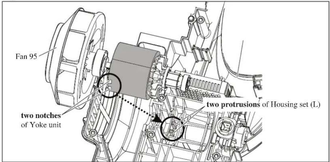
2) Fit two notches of Yoke unit to two protrusions on Housing set (L). (Fig. 4)
3) Before assembling Housing set (R), mount Hanger on Housing set (L) and (R). (Fig. 2)
Fig. 4
[2]-2. Switch unit
DISASSEMBLING
(1) Remove Housing set (R) from Housing set (L). (Figs. 1 and 2) It is not necessary to remove Motor section.
(2) Remove Switch unit by disconnect Connectores as illustrated in Fig. 5.
Fig. 5

ASSEMBLING
Take the disassembling step in reverse.
▶ Circuit diagram
Fig. D-1
| Color index of lead wires' sheath | |||
| Black | White | ||
| Red | Blue | ||
| Yellow | |||
Connect Line filters as illustrated below if they are used.

▶ Wiring diagram in Housing set (L)
Fig. D-2


- 9
- Symbols
- Symboles
- SPECIFICATIONS
- Model BUB360
- Intended use
- General Power Tool Safety Warnings
- BLOWER SAFETY WARNINGS
- SAVE THESE INSTRUCTIONS.
- WARNING:
- IMPORTANT SAFETY INSTRUCTIONS
- FOR BATTERY CARTRIDGE
- Tips for maintaining maximum battery life
- FUNCTIONAL DESCRIPTION
- CAUTION:
- Installing or removing battery cartridge (Fig. 1)
- Battery protection system
- Switch action (Fig. 2)
- ASSEMBLY
- Installing or removing the long nozzle (Fig. 3 & 4)
- Installing the shoulder strap (Fig. 5)
- OPERATION
- Blowing (Fig. 6)
- MAINTENANCE
- Cleaning (Fig. 7)
- Replacing carbon brushes (Fig. 8 & 9)
- ACCESSORIES
- SPÉCIFICATIONS
- Modèle BUB360
- For European countries only
- EC Declaration of Conformity
- FRANÇAIS
- DEUTSCH ITALIANO
- PORTUGUÊS DANSK
- ΕΛΛΗΝΙΚΑ
- ENGLISH
- Noise
- Wear ear protection
- Vibration
- Bruit
- CONCEPT AND MAIN APPLICATIONS
- Specification
- Standard equipment
- ▶ Optional accessories
- Repair
- [1] NECESSARY REPAIRING TOOLS
- [2] DISASSEMBLY/ASSEMBLY
- [2]-1. Fan, Armature
- DISASSEMBLING
- [2]-1. Fan, Armature (cont.)
- ASSEMBLING
- [2]-2. Switch unit
- ▶ Circuit diagram
- ▶ Wiring diagram in Housing set (L)
Brand : MAKITA
Model : BUB360Z
Category : Blower