SLK980RVS - Basket Pelgrim - Free user manual and instructions
Find the device manual for free SLK980RVS Pelgrim in PDF.

User questions about SLK980RVS Pelgrim
0 question about this device. Answer the ones you know or ask your own.
Ask a new question about this device
Download the instructions for your Basket in PDF format for free! Find your manual SLK980RVS - Pelgrim and take your electronic device back in hand. On this page are published all the documents necessary for the use of your device. SLK980RVS by Pelgrim.
USER MANUAL SLK980RVS Pelgrim
text_image
Technical diagram showing a device interior with labeled components C and D, including a central fan or vent.SLK650
natural_image
Diagram of a device with two rectangular compartments and a labeled component 'E' (no text or symbols beyond label)
Reinigen
Afzuigkap
natural_image
Technical line drawing of a cabinet with open door and side view, showing internal components (no text or symbols)natural_image
Technical diagram showing two mechanical assembly configurations with no visible text or symbolsMotorloze afzuigkap
Spanning 230 V - 50 Hz X X X X
precautions you must take 18
extraction systems 18
control
control switches 19
visor switches 19
intensive setting (SLK680/980) 20
timer (SLK680/980) 20
grease filter indication (SLK680/980) 20
maintenance
carbon filters 20
assembling the carbon filter .....21
removing filter panel/changing the light bulbs .....21
cleaning 22
installation
general 23
building-in dimensions 23
mounting the cooker hood 24
mounting the cover 25
cooker hood with remote motor unit .....25
disposal of packaging and appliances .....26
technical specifications .....26
MSL600

SLK600
SLK650

text_image
Ⅲ Ⅱ Ⅰ 0 2 1SLK680/980
text_image
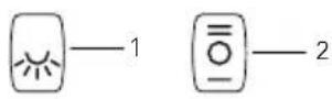
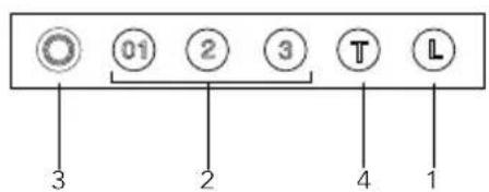
01 2 3 T L 3 2 4 1Description
- lighting on/off
- speed switch
- indicator light
- intensive setting
Introduction
When you have read these instructions for use, you will quickly be aware of all the facilities the appliance can offer you. You can read about safety and how you should look after the appliance.

Keep the instructions for use and the installation instructions. Any later user of this appliance could benefit from them.

Precautions you must take
■ Have the appliance connected by a qualified fitter (see section "Installation").
■ The power supply must be disconnected before the appliance is cleaned or repaired. Remove the plug from the socket or switch the electricity off at the mains.
■ When cooking, the hob becomes hot, children should always be kept at a distance.
■ Fats and oils become inflammable on overheating. Never leave such foods unattended during preparation.
■ We advise you to switch the cooker hood on before you start cooking. Leave the cooker hood on for another 5 minutes or so after you have finished cooking.
■ A grease-saturated filter mat is inflammable, so never flambé under the cooker hood, and clean the filter regularly.
■ Replacing the light bulbs: first switch the electricity off! Only use the same sort of light bulbs with the same Wattage.
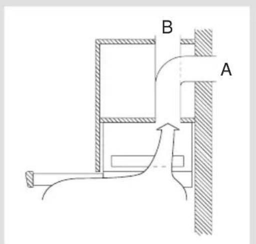
Extraction systems
Some cooker hoods can be connected in one of two ways:
■ To a duct (A), the cooking vapours extracted by suction are carried outside, once the grease particles have been filtered. This is the best method.
■ As a recirculation hood, the grease particles and the smell in the extracted vapours are filtered and the air streams back into the kitchen through the opening (B).
text_image
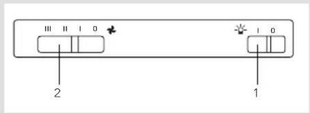
B AControl switches
- lighting on/off
- speed switch
- indicator light
- intensive setting
MSL600 SLK600

text_image
1 1 2SLK650
text_image
Ⅲ Ⅱ Ⅰ 0 2 1 Ⅰ 0SLK680/980

text_image
3 2 3 T LVisor switches
The visor switches only work if the light and fan switches are switched on. If you pull the visor open the light and fan will go on.
Memory (SLK680/980)
When you close the visor when the motor is still running, the fan switches off. The cooker hood remembers the chosen speed setting. The indicator light will stay on to indicate this (green = setting 1, orange = setting 2, red = setting 3, flashing red = setting 4).

The internal timer that keeps track of the working hours will keep running during this period. Therefore the grease filter indication (see page 20) will be inaccurate.
If you pull the visor fully open again the fan will switch on again with the last chosen speed setting.

Intensive setting (SLK680/980)
You can temporarily switch the extractor hood to the highest setting – in order, for example, to remove the odour quickly if something has burned.
Press switch to switch to the intensive setting. The extractor hood switches to its highest setting (4) for 5 minutes, and then switches back to the original setting.
Timer (SLK680/980)
Press switch ,00r for 2 seconds. The extractor hood remains at the selected setting for 5 minutes, after which the extractor hood and the lighting are automatically switched off.
Grease filter indication (SLK680/980)
The degree of saturation of the grease filter is indicated by means of a luminous display.
If button is pressed when the extractor hood is switched off, the display lights up; the colours displayed have the following meanings:
■ green light: in use for less than 6 working hours
■ yellow light: in use for 6 to 12 working hours
■ red light: in use for more than 12 working hours (the grease filter should be cleaned or, if necessary, replaced).
Carbon filters
The carbon filter must be used if the cooker hood is not connected to a duct (see extraction systems on page 18).
Note:
■ The carbon filter must be replaced at least twice a year, depending on how much the cooker hood is used.
■ Carbon filters cannot be cleaned to use again.
■ Saturated carbon is harmful to the environment, replace the filter regularly.
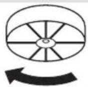
Fitting the carbon filter
SLK 600/650/680/980
Centre the carbon filter with the sunken round surface on top of the motor frame and turn it to the right.
Removing filter panel/changing the light bulbs
First switch the electricity off.
MSL600/SLK600
Pull out the visor (C). Press the handle (D) slightly. Remove the filter panel
Remove the carbon filter (if applicable) to change the lam p.

text_image
C DSLK650
Pull out the visor (C). Press the handle (D) slightly. Remove the filter panel
Remove the plastic cover (B) to change the light.

text_image
D B CRemoving filter panel/changing the light bulbs
First switch the electricity off.
SLK680/980
Pull out the visor (C). Press the handle (D) slightly. Remove the cover (B) by turning it counterclockwise. Pull the bulb out of the holder, then fit the new bulb. Take care not to touch the bulb with your hands when you replace it, since direct contact with the skin can result in the bulb burning out.

text_image
D B CSLK980
The filter panel can be taken apart in 2 pieces. Be careful not to damage the fixing guide (E).

natural_image
Diagram of two rectangular electronic components with internal arrows indicating movement or force, labeled 'E' (no text or symbols beyond label)
Cleaning
Cooker hood
Clean the cooker hood with soapy water, then wipe with clean water to rinse. Do not use aggressive cleaning agents such as soda. The cooker hood paintwork will stay looking nice if you wax it occasionally.
Filters
■ Wash aluminium filters, every week in soapy water. The cleaning agents will make the aluminium filter turn dull, this is normal.
■ Some models are fitted with fibre filters. These can only be washed once or twice and must therefore be replaced regularly.
■ The carbon filters cannot be cleaned to use again.
General
This appliance should be connected to the power supply by a recognized fitter who is familiar with, and works according to the correct safety regulations.
Important that you know:
■ If the cooker hood is to be fitted to an existing duct no other appliances, such as a geyser or heater, may be connected to that same duct.
■ Consider local regulations with respect to the ventilation of gas appliances!
■ The cooker hood should be mounted at least 650 mm above the hob.
■ The shorter the duct, and the fewer the bends in it, the better the cooker hood will work.
■ Before you start drilling check that there are no installation cables present.

Building-in dimensions
MSL600/SLK600 SLK650

text_image
598 510 Ø 125 150 40 265 200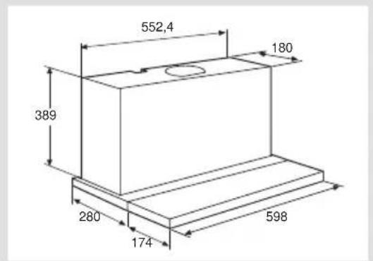
text_image
552,4 180 389 280 174 598SLK680 SLK980

text_image
598 510 230 34 280 c 150
text_image
898 810 Ø 150 230 34 280Mounting the cooker hood
MSL600/SLK600/SLK680/SLK980
Drill 4 holes in the bottom of the wall cupboard, using the stencil provided (H). Also saw the hole for the duct.
Using the 4 screws supplied, fix the cooker hood to the bottom of the cupboard. Make sure that the front of the cooker hood does not stick out in front of the side of the cupboard (G).

text_image
H GSLK650
Drill 2 holes (A) in the sides of the cabinet. Also saw the hole for the duct. Insert the cooker hood into the cabinet until the two retaining springs (A) are fixed into the previously drilled holes.
From the inside of the hood insert four screws (B) supplied with the hood. If the sides of the cabinet are thicker than 18 mm and the cooker hood can not be installed due to the plastic spacers (B), please remove the spacers.
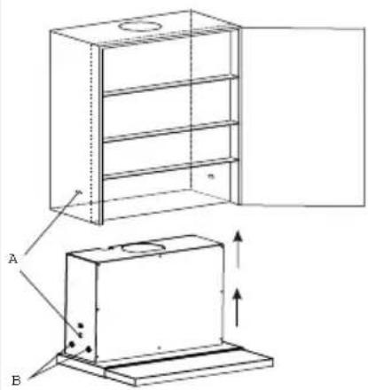
text_image
Technical diagram showing a cabinet with labeled components A and B, including a door open and internal structure with directional arrows.The handle may be replaced by other material, e.g. the same material used for the kitchen cupboards or the light strip. The handle is fitted from the back with screws.
Connect the cooker hood outlet flange (P) to the duct (A). Put the plug in the wall socket.
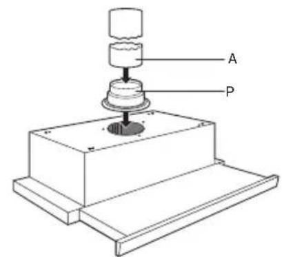
text_image
A PMounting the cover

If the cupboard is deeper than the cooker hood, you can mount the cover via the slotted holes on the back of the hood. The depth can be adjusted from 20 to 60 mm

natural_image
Technical line drawing of a mechanical assembly with two views: top shows a pipe connection, bottom shows a structural beam with fasteners (no text or symbols)Cooker hood with remote motor unit
This cooker hood can only be used in combination with a mechanical ventilation system. The extraction is regulated with a switch on the motor unit.
The motor unit must be single phase (230 V-50Hz) with various speeds. Whichever method of extraction is selected, it must never be possible to switch the motor unit off (see for this only the motor unit manual). The various possibilities are often given in terms of: Medium or day setting, high or cooking setting.
Disposal of packaging and appliances
The packaging of the appliance is recyclable. It is made up off:
-cardboard
- polyethylene
– CFC free polystyrene (PS rigid foam)
– polypropylene straps around the box
Please dispose of these materials in a responsible way in accordance with the regulations of your local authority.
Your local authority will also be able to give you information about disposing disused household appliances in a responsible way
Technical specifications
Type MSL600 SLK600 SLK650 SLK680/980
Power 230 V - 50 Hz X X X X
Nominal capacity W 80 210 325 240
Motor W - 130 300 200
Lighting W 2x40 2x40 PL 11 2x20
Carbon filter - KF20 KF20 KF80
votre hotte
description 28
introduction 29
sécurité
recommendations 30
text_image
3 2 3 T Lnatural_image
Diagram of a device with two rectangular compartments and labeled component E, showing internal structure and directional arrows (no text or symbols beyond label)Nettoyage
Hotte
natural_image
Technical line drawing of a cabinet with open door and side view, showing internal components (no text or symbols)natural_image
Technical line drawing of a structural assembly with two views (top and side), showing pipe connections and support components without any text or symbols.Tension 230 V - 50 Hz X X X X
text_image
Technical diagram showing a device interior with labeled components C and D, including a central fan or vent.SLK650
natural_image
Diagram of a device with two rectangular compartments and labeled component E, showing internal structure and directional arrows (no text or symbols beyond label)