BSK1250RVS - Basket Pelgrim - Free user manual and instructions
Find the device manual for free BSK1250RVS Pelgrim in PDF.

User questions about BSK1250RVS Pelgrim
0 question about this device. Answer the ones you know or ask your own.
Ask a new question about this device
Download the instructions for your Basket in PDF format for free! Find your manual BSK1250RVS - Pelgrim and take your electronic device back in hand. On this page are published all the documents necessary for the use of your device. BSK1250RVS by Pelgrim.
USER MANUAL BSK1250RVS Pelgrim
natural_image
Exterior view of a stainless steel kitchen air conditioner unit (no text or symbols visible)BSK950
BSK1250
Pelgrim
Instructions for use cooker hood
NL
natural_image
Diagram of a brick wall with a ladder and directional arrows indicating movement or force (no text or symbols)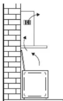
text_image
Diagram showing a vertical structure with directional arrows and a labeled component, possibly illustrating a mechanical or structural assembly.Bediening
text_image
- + 1 2 3 4 5natural_image
Illustration of a hand inserting a card into a clipboard (no text or symbols visible)Koolstofffilter
natural_image
Architectural wireframe diagram of a grid-patterned roof or foundation structure (no text or symbols)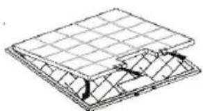
natural_image
Isometric line drawing of a solar panel structure with grid lines and mounting points (no text or symbols)Verlichting
text_image
Diagram illustrating a scientific experiment with labeled components A, B, and C, showing a pipette setup and directional arrows.natural_image
Diagram of a mechanical or electrical component with wires and directional arrows, no visible text or symbolsMontage
text_image
Technical diagram of a mechanical device with labeled components A through F, including a zoomed-in view and assembly details.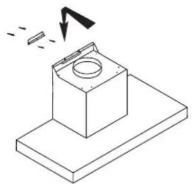
natural_image
Isometric line drawing of a mechanical component with a circular top and base, showing a downward arrow and dashed lines indicating motion (no text or symbols)
natural_image
Isometric line drawing of a mechanical assembly with no visible text or symbolsMontage
natural_image
Isometric line drawing of a mechanical assembly with a magnified inset showing a detail (no text or symbols)Afvoeren
text_image
Warning symbol for a trash bin with crossed x-marks and a blank rectangular basenatural_image
Diagram of a brick wall with a wall-mounted fixture and directional arrows indicating motion (no text or symbols)
text_image
Diagram showing a brick wall with a door and directional arrows indicating movement or force, likely illustrating a physics or engineering concept.
Commandes

text_image
1 2 3 4 5natural_image
Illustration of a hand holding a clipboard with a curved arrow indicating motion (no text or symbols)Filtre à charbon

natural_image
Architectural wireframe diagram of a roof structure with grid pattern (no text or symbols)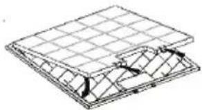
natural_image
Technical line drawing of a structural panel or enclosure with grid lines and internal components (no text or symbols)Les lampes
text_image
Diagram illustrating a scientific apparatus with labeled components A, B, and C, showing a rotating disk and directional arrow.text_image
Diagram illustrating a mechanical or electrical setup with labeled components and directional arrows, likely for system or control analysis.Montage
text_image
Technical diagram of a mechanical device with labeled components A through F, including a zoomed-in view and assembly details.
natural_image
Isometric line drawing of a mechanical component with a circular top and base plate, showing a downward arrow indicating motion (no text or symbols)
natural_image
Isometric line drawing of a mechanical assembly with no visible text or symbolsMontage
natural_image
Isometric line drawing of a mechanical assembly with a magnified inset showing a detail (no text or symbols)Mise au rebut
text_image
Warning symbol for a trash bin with crossed x-marks and no textnatural_image
Diagram of a wall-mounted electrical cabinet with directional arrows indicating airflow or movement (no text or symbols)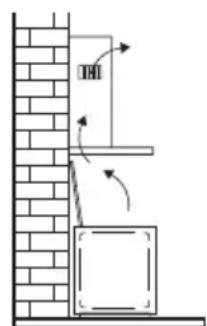
text_image
THIBedienung
text_image
- + 1 2 3 4 5natural_image
Illustration of a hand holding a clipboard with a curved arrow inside, no text or symbols presentKohlefilter
natural_image
Isometric line drawing of a grid-patterned structure with no text or symbols
natural_image
Isometric line drawing of a roof structure with grid lines and triangular supports (no text or symbols)Lampen
text_image
Diagram illustrating a scientific apparatus with labeled components A, B, and C, showing a rotating disk and directional arrows.natural_image
Diagram of a mechanical device with a hand operating a sensor or probe, connected to a box and two reference points (no text or symbols present)Montage
text_image
Technical diagram of a mechanical assembly with labeled components A through F, including a base platform and component details.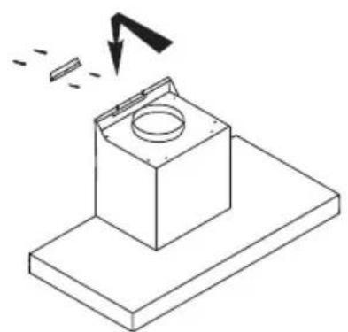
natural_image
Isometric line drawing of a mechanical component with a circular top and base plate, showing a downward arrow indicating motion (no text or symbols)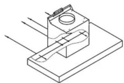
natural_image
Isometric technical diagram of a mechanical assembly with directional arrows indicating flow or movement (no text or symbols)Montage

natural_image
Isometric line drawing of a mechanical assembly with a magnified inset showing a detail (no text or symbols)Entsorgung
natural_image
Symbol of a trash bin with crossed x-marks and a blank rectangular base (no text or numbers)| Precautions you must take | 5 | |
| Extraction systems |
Use
| Controls | 7 |
Maintenance
| Cleaning | 9 | ||
| Grease | filters | ||
| Carbon | filter | ||
| Lighting | 10 |
Installation
| General | 11 | |
| Electrical | connection | |
| Mounting | 13 |
Appendix
| Disposal | 15 |
Description
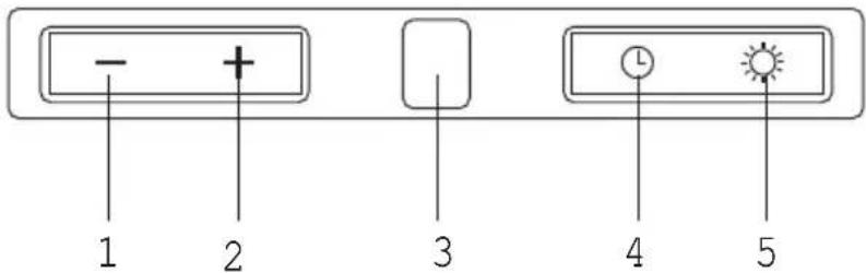
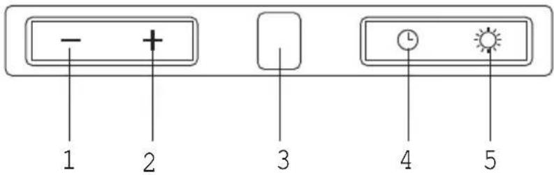
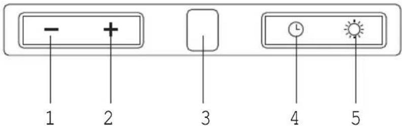
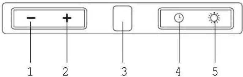
text_image
- + 1 2 3 4 5- Fan setting (lower speed)
- Fan setting (higher speed)
- Fan setting display
- Timer
- Light bulbs
Introduction
This user manual gives you a quick overview of all the possibilities offered by the appliance. You will find information on safety measures and maintaining the appliance.

Please retain this user manual and the installation guide. They may be of use to future users of the appliance.
Precautions you must take
Make sure the appliance is installed by an authorised installer (see "Installation" chapter). Do not connect the appliance to the mains before completing the installation.
- Connect the appliance in accordance with the applicable regulations in your area.
- We advise you to wear protective work gloves during the installation of the cooker hood because of possible sharp edges.
- The appliance has been manufactured in accordance with the latest safety standards. However we do advise that persons with a mental or motor impairment do not use this appliance without the proper supervision of a competent person. The same applies to children.
- Never use the cooker hood if the grease filter has not been properly installed!
• Do not lean against the cooker hood. - Never place objects on the hood unless specifically indicated.
- Make sure there is sufficient ventilation when you use the cooker hood on a gas cooker.
- The exhaust must never be connected to a flue that is also used for other heating appliances.
- Never flambé under the cooker hood and always clean the filters promptly. Never leave frying pans unattended during use, as the heated fat may catch fire.
- The cooker hood needs to be cleaned regularly (at least once a month) on the inside as well as on the outside. Insufficient cleaning or late replacement of filters may pose a fire hazard.
- If the connection cable becomes damaged, it should be replaced by the manufacturer's service department or by a person with equivalent qualifications, in order to prevent dangerous situations from arising.
- Attention! Intensive use may cause condensation to form on the cooker hood. Condensation can be removed easily with a dry cloth.
Precautions you must take
- When replacing the lights, first disconnect the appliance from the mains! Only use identical lamps with the wattage indicated. Only use the cooker hood with lamps installed, in order to reduce the risk of electric shock.
- Accessible parts may become hot when used with cooking appliances.
- The grease filters become hot during operation. Wait a minimum of 30 minutes after cooking before cleaning the filters.
- The power must be switched off during repairs or cleaning. Remove the plug from the mains socket or turn the switch in the meter cupboard to zero.
- Grease and oil are flammable when they are overheated. Stay in the vicinity of the cooker when preparing food.
- We will not accept any responsibility for any faults, damage to the appliance, or fires resulting from non-observance of the instructions included in this manual.
Extraction systems
Depending on the type, the cooker hoods can be connected in one of two ways:
-
To a duct. The cooking vapours extracted by suction are carried outside, once the grease particles have been filtered. This is the best method.
-
Recirculation hood. When the hood is connected as a recirculation hood, the grease particles and odour in the extracted vapours are filtered.
The extracted air is not carried outside but recirculates in the kitchen. In this case you must have a carbon filter fitted.

Attention! The carbon filter needs to be ordered separately.
natural_image
Diagram of a wall-mounted electrical cabinet with directional arrows indicating airflow or movement (no text or symbols)
text_image
Diagram showing a vertical structure with directional arrows and a box, possibly illustrating a physics or engineering concept.Controls

text_image
- + 1 2 3 4 5Switching fan on and off
Press the '+' button (2).
The cooker hood switches on at setting 1.
Press the '+' button (2) again.
The cooker hood switches to a higher speed. After speed three the cooker hood switches to an intensive setting. After 10 minutes this switches back to speed 3.
At each speed, the relevant setting is shown in the display (3).
Press the '-' (1) button to switch off the cooker hood.
The display counts down to '0' (every time the '-' button is pressed) and then the cooker hood switches off.
Switching lighting on and off
Press the lighting button (5).
The lighting switches on.
Each time the light button (5) is pressed briefly the light dims by 25%.
Choose between 100%, 75% or 50% light intensity.
Keep the light button (5) pressed down for a few seconds.
The light goes off.
Controls
text_image
- + 1 2 3 4 5Timer function
The timer function can be used to switch the cooker hood off automatically after a certain period of time. The shutoff time can be set at intervals of 10 minutes up to a maximum of 90 minutes.
Switching off the cooker hood automatically
Switch the cooker hood on and press the timer button (4).
The display flashes and a dot appears in the display, indicating that the timer function is active.
Set the shutoff time using the '+' button (2).
Each setting in the display corresponds to a shutoff time of 10 minutes.
• 1 in display = 10 minutes
• 2 in display = 20 minutes
- etc.
Press the timer button (4).
The set time and speed are saved. The display stops flashing and shows the set speed. A flashing dot in the display indicates that the timer function is active.
Press the timer button again to stop the timer function.
If the time and speed set using the timer function are not saved within 20 seconds, the timer function switches off again.
Switching button illumination on and off
Press and hold the timer button (4) for a few seconds.
The button illumination comes on.
Press and hold the timer button (4) again for a few seconds.
The illumination switches off.
Cleaning
Attention! Before performing any maintenance operation, isolate the hood from the electrical supply by unplugging the appliance or switching off your household's master switch. The cooker hood should be cleaned regularly (at least as frequently as the grease filters are cleaned) both internally and externally. Do not use abrasive products.
Do not use alcohol!
Attention! Failure to comply with the basic recommendations for cleaning the cooker hood and cleaning/replacing the filters may lead to a fire. Therefore, we recommend that you observe these instructions. The manufacturer declines all responsibility for any damage to the motor or any fire damage linked to inappropriate maintenance or failure to observe the above safety recommendations.
Cooker hood
Clean the cooker hood with soapy water and a soft cloth. Then wipe with clean water to rinse. Do not apply aggressive cleaning agents such as caustic soda. The paintwork on the cooker hood will remain shiny if it is periodically rubbed with wax.

Stainless steel canopy hoods
Do not use any sort of scourer. Treat with a stainless steel care product and polish with the structure of the stainless steel.
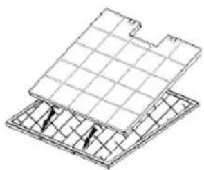
Metal grease filters
These must be cleaned once a month (or when indicated by the filter saturation indication system, if present on your model) using non-aggressive detergents, either by hand or in the dishwasher, which must be set to a low temperature and a short cycle. The openings must be placed downwards to let the water run out of the filters. When washed in a dishwasher, aluminium grease filters may be discoloured slightly. This is normal and does not affect their filtering capacity.
Grease filters

natural_image
Diagram of a hand holding a clipboard with a curved object inside, no text or symbols presentCarbon filter
natural_image
Isometric line drawing of a grid-patterned structure with no text or symbols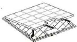
natural_image
Technical line drawing of a structural panel with grid lines and internal components (no text or symbols)Light bulbs

text_image
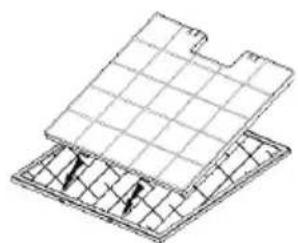
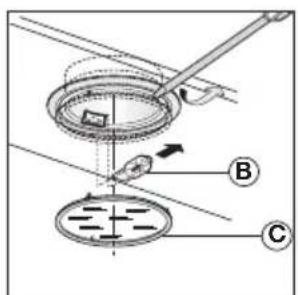
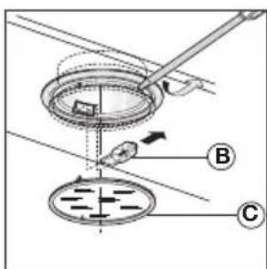
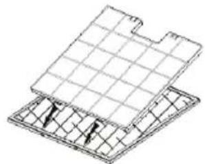
Diagram illustrating a scientific apparatus with labeled components A, B, and C, showing a circular component and directional arrows.Removing the grease filters
Switch off the electricity! Remove the plug from the mains socket or turn the switch in the meter cupboard to zero. Release the lock of the fat filer and tilt the filter downwards.
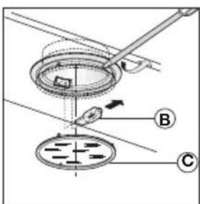
Replacing the carbon filter
The carbon filter must always be used if the cooker hood is not ducted.
- Remove the grease filters
- Attach the carbon filters to the filter.
- Replace the grease filters.
Note:
- Saturation of the activated charcoal will eventually occur after prolonged use, depending on the type of cooking and how frequently the grease filter is cleaned.
• The carbon filter needs to be replaced at least every four months. - The carbon filter cannot be washed for reuse. Saturated carbon is not environmentally friendly. Change the filter regularly.
Changing the light bulbs
Disconnect the hood from the electricity.
Warning! Prior to touching the light bulbs ensure they are cooled down.
- Remove the light glass by lifting it upwards with a small screwdriver or something similar.
- Replace the globe with a new globe of the same wattage.
Warning! Follow package directions and do not touch new light with bare hands. - Replace the light glass (clicks into position).
If the lights do not work, make sure that the lamps are fitted properly into their housings before you call for technical assistance.
General
This appliance must be connected to the electric mains by an authorised installer who is familiar with the safety precautions and will carry them out. The appliance is in compliance with European guidelines.
Important information:
- The distance between the lowest point of the cooker hood and a gas hob must be at least 65 cm. If using an electric, ceramic or induction hob, this distance must be at least 55 cm.
- If the cooker hood is connected to an existing exhaust duct, no other appliance must be connected to the duct (such as a hot water heater or a stove).
- Consider local regulations with respect to the ventilation of gas appliances.
- The shorter the duct, and the fewer bends in it, the better the cooker hood will work.
- Check before you start drilling that no installation pipe(s) is/are present.
- The connection pipe to the cooker hood has a diameter of 125 or 150 mm. We recommend that the exhaust pipe has as large a diameter as possible.
- The enclosed installation materials are suitable for reinforced concrete and brick walls. For some types of wall you may need special plugs and screws.
Electrical connection
This appliance is fitted with an earthed plug, which should be connected to an earthed wall socket.
Check that the voltage indicated on the rating plate matches the voltage of your household supply.
The appliance should be connected to the mains as follows:
BROWN = L live
BLUE = N neutral
GREEN/YELLOW = earth
This cooker hood is fitted with a connector plug. Install the cooker hood so that the plug is accessible.
Attention!
If you are making a fixed connection, you must ensure that a double pole switch with an air gap of at least 3 mm is fitted in the supply line.
max. 150 mm

natural_image
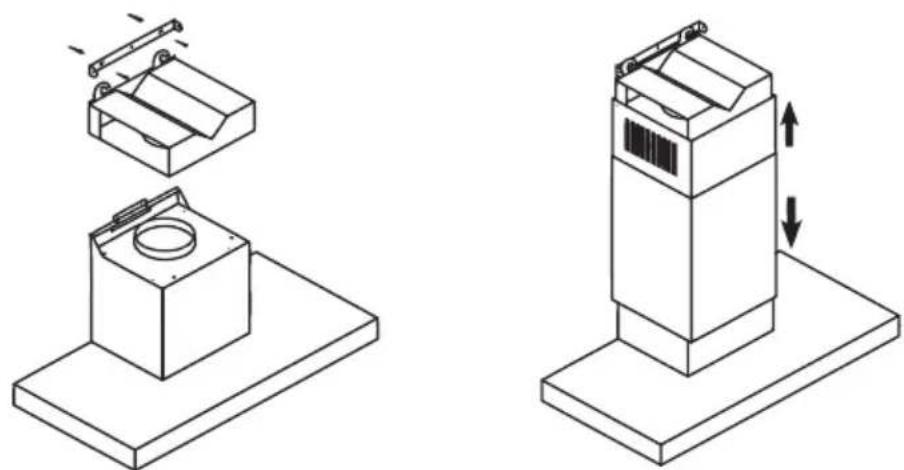
Diagram of a mechanical or electrical setup with a box, wires, and directional indicators (no text or symbols present)Mounting
• Draw a vertical line on the wall from the middle of the hob.
- Place the fixing bracket (F) against the wall so that the vertical line is exactly in the middle of the fixing bracket (F). Ensure that the fixing bracket (F) is perfectly level.
- Mark the positions of the mounting holes on the wall. Drill the mounting holes in the wall. Take into account the diameter of the fixing plugs. Position the plugs in the wall and screw the fixing bracket (F) to the wall.
- Attach the cooker hood (A) to the fixing bracket (F). Align the cooker hood with the set screws and screw the hood to the bracket (F).

text_image
Technical diagram of a mechanical device with labeled components A through F, including a zoomed-in view and assembly details.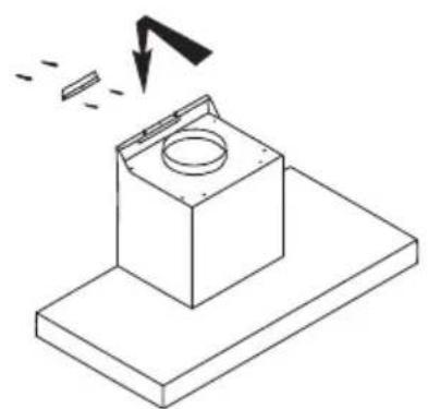
natural_image
Isometric line drawing of a mechanical component with a circular top and base plate, showing a downward arrow indicating motion (no text or symbols)
natural_image
Isometric line drawing of a mechanical assembly with no text or symbolsMounting

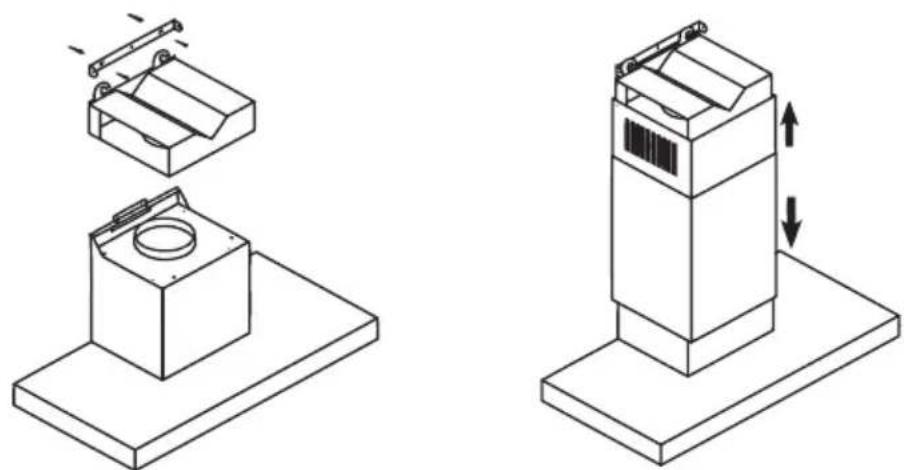
- Position the bracket (E) for attaching the exhaust duct (C) on the vertical line, 65 mm below the marked maximum height of the exhaust duct (C). Mark the positions of the mounting holes for the bracket (E), drill the holes, position the plugs and screw the bracket (E) to the wall.
- If necessary, install the air deflector (D) for recirculation use.
- Connect the cooker hood to the mains.
Position the exhaust duct (B+C) on the cooker hood and screw it to the upper bracket (E) with the corresponding screws.

natural_image
Isometric line drawing of a mechanical assembly with a magnified inset showing a detail (no text or symbols)Disposal
Disposal of appliance and packaging
This appliance was manufactured using sustainable materials. It must be disposed of responsibly at the end of its life cycle. The local authorities can provide you with the relevant information.
The packaging of this appliance is recyclable. It may have been made from:
- cardboard;
• polythene film (PE);
• CFRP-free polystyrene (PS hard foam).
You need to dispose of these materials responsibly in accordance with official regulations.

natural_image
Symbol of a trash bin with crossed x-marks and a blank rectangular base (no text or numbers)To draw attention to the fact that the segregated processing of household electrical appliances is compulsory, this appliance carries the symbol of a crossed-out dustbin. This means that you may not dispose of the appliance as household refuse at the end of its useful life. Instead, it should be taken to a special segregated refuse collection centre run by the local authority or to a dealer providing this service.
Segregated processing of household appliances prevents any negative impact on the environment and public health that might otherwise arise. It allows the recovery of the materials used to manufacture this appliance, thus generating considerable savings in terms of raw materials and energy.
CE
Declaration of conformity
We hereby declare that our products satisfy the applicable European directives, orders and regulations, as well as the requirements stated in the referenced standards.