BSK1000MAT - Basket Pelgrim - Free user manual and instructions
Find the device manual for free BSK1000MAT Pelgrim in PDF.

User questions about BSK1000MAT Pelgrim
0 question about this device. Answer the ones you know or ask your own.
Ask a new question about this device
Download the instructions for your Basket in PDF format for free! Find your manual BSK1000MAT - Pelgrim and take your electronic device back in hand. On this page are published all the documents necessary for the use of your device. BSK1000MAT by Pelgrim.
USER MANUAL BSK1000MAT Pelgrim
natural_image
Hand holding a metal tray with a mesh cover, partially open by an open shelf (no text or symbols visible)BSK1000
Pelgrim
Instructions for use cooker hood
700004147000
Pelgrim
NL
natural_image
Diagram of a staircase with brick wall and adjacent equipment, showing airflow direction (no text or symbols)
natural_image
Diagram of a vertical structure with brick wall and adjacent equipment, showing airflow or movement arrows (no text or symbols)
Bediening
text_image
1 2 3 4natural_image
Illustration of a hand holding a small object inside a folded paper or folder (no text or symbols visible)Koolstofffilter

text_image
OK!Verlichting
text_image
Diagram illustrating a mechanical or scientific setup with labeled components A, B, and C, showing a central component and directional arrows.natural_image
Diagram of a mechanical or electrical component with a hand holding a sensor and connected to a box, showing wiring and alignment lines (no text or symbols)Montage
text_image
Technical diagram showing a mechanical assembly with labeled components and motion indicators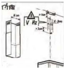
text_image
V X cm V Hz + 10cm X .2cm + 3cmtext_image
Diagram illustrating a mechanical or electrical process with a device and directional arrows indicating motion or force.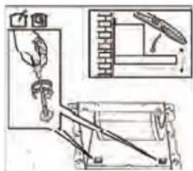
natural_image
Technical diagram showing mechanical assembly with spring-loaded components and a lever mechanism (no text or labels)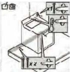
text_image
Technical diagram showing mechanical assembly with labeled components x1 and x2, including directional arrows and dimension lines.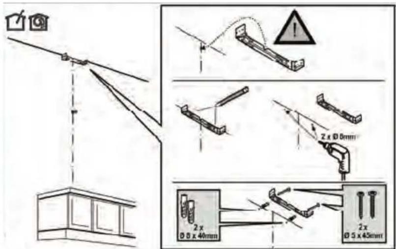
text_image
Diagram illustrating cable installation and wire penetration with labeled dimensions and safety warningnatural_image
Symbol of a trash bin with crossed x-marks and a blank rectangular base (no text or numbers)natural_image
Diagram of a brick wall with a door and ceiling-mounted fixture, showing airflow direction (no text or symbols)
natural_image
Diagram of a brick wall with a cabinet and directional arrows indicating movement or force (no text or symbols)
natural_image
Illustration of a hand inserting a card into a folder (no text or symbols visible)text_image
Diagram illustrating a mechanical or electrical setup with labeled components A, B, and C, showing a lever and component layout.text_image
Diagram illustrating a mechanical or electrical setup with labeled components and directional arrows, likely for system or control analysis.Montage

text_image
Diagram showing a kitchen setup with a candle, a magnified view of the candle, and a tool on a stove with four panes.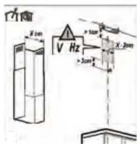
text_image
V X 2cm V Hz + 5cm X . 2cm + 3cm R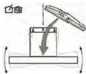
text_image
Diagram illustrating a mechanical or electrical setup with a lever and rotating component, labeled with Chinese characters.
natural_image
Technical diagram showing a mechanical setup with a lever, brick wall, and structural frame (no text or symbols)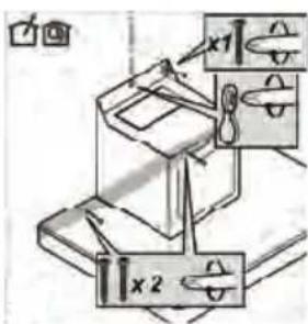
text_image
Diagram showing two labeled mechanical components with coordinate axes x1 and x2, likely illustrating a mechanical or electrical setup.text_image
Diagram illustrating cable installation and wire penetration with magnified views showing 2x, 5x, and 40mm measurements.natural_image
Diagram showing a mechanical setup with an inset close-up of a tool interacting with a component (no text or symbols visible)text_image
Diagram of a house with a scale and directional indicators, including a 2x2 grid and a checkmark symbol.ANNEXE
Ihre Haube
natural_image
Diagram of a staircase with brick wall and elevator shaft, showing airflow direction (no text or symbols)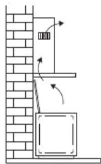
natural_image
Diagram of a vertical structure with brick wall and adjacent panel, showing airflow or movement arrows (no text or symbols)
Bedienung
text_image
1 2 3 4natural_image
Illustration of a hand holding a small object over two stacked panels, with no visible text or symbols.Kohlefilter

text_image
OK!Beleuchtung

text_image
Technical diagram showing a mechanical assembly with labeled components A, B, and C, including a central component and directional arrows.text_image
Diagram illustrating a mechanical or electrical setup with labeled components and directional arrows, likely for electrical or mechanical analysis.Montage
text_image
Technical diagram showing a mechanical assembly with labeled components and dimension arrows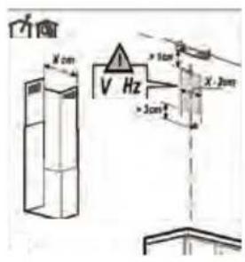
text_image
V X cm V Hz > 10cm X 20m > 30cmtext_image
Diagram illustrating a mechanical or electrical setup with a lever and rotating components, labeled with Chinese characters.
natural_image
Technical line drawing of a mechanical device with components and an inset view (no text or symbols)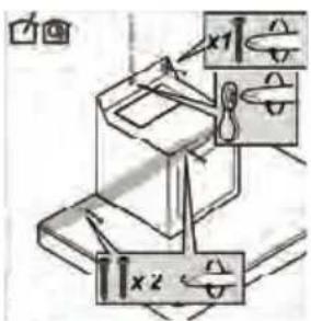
text_image
Technical diagram showing mechanical assembly with labeled components x1 and x2, including directional arrows and a magnified inset.
text_image
Diagram illustrating cable installation and wire repair process with labeled dimensions and warning symbolsnatural_image
Symbol of a trash bin with crossed x-marks and a blank base (no text or numbers)| Precautions you must take | 5 |
| Extraction systems | 6 |
Use
| Controls | 7 |
Maintenance
| Cleaning | 8 | |
| Grease filters | 9 | |
| Carbon filter | 9 | |
| Lighting | 9 |
Installation
| General | 10 | |
| Electrical connection | 11 | |
| Mounting | 12 | |
Appendix
| Disposal | 14 |
Description
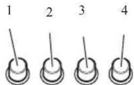
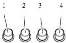
text_image
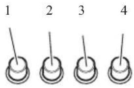
1 2 3 4- Lighting
- Switch off / fan position 1
- Fan position 2
- Fan position 3
Introduction
This user manual gives you a quick overview of all the possibilities offered by the appliance. You will find information on safety measures and maintaining the appliance.

Please retain this user manual and the installation guide. They may be of use to future users of the appliance.
Precautions you must take
Make sure the appliance is installed by an authorised installer (see "Installation" chapter). Do not connect the appliance to the mains before completing the installation.
- Connect the appliance in accordance with the applicable regulations in your area.
- We advise you to wear protective work gloves during the installation of the cooker hood because of possible sharp edges.
- The appliance has been manufactured in accordance with the latest safety standards. However we do advise that persons with a mental or motor impairment do not use this appliance without the proper supervision of a competent person. The same applies to children.
- Never use the cooker hood if the grease filter has not been properly installed!
- Do not lean against the cooker hood.
- Never place objects on the hood unless specifically indicated.
- Make sure there is sufficient ventilation when you use the cooker hood on a gas cooker.
- The exhaust must never be connected to a flue that is also used for other heating appliances.
- Never flambé under the cooker hood and always clean the filters promptly. Never leave frying pans unattended during use, as the heated fat may catch fire.
- The cooker hood needs to be cleaned regularly (at least once a month) on the inside as well as on the outside. Insufficient cleaning or late replacement of filters may pose a fire hazard.
- If the connection cable becomes damaged, it should be replaced by the manufacturer's service department or by a person with equivalent qualifications, in order to prevent dangerous situations from arising.
- Attention! Intensive use may cause condensation to form on the cooker hood. Condensation can be removed easily with a dry cloth.

Precautions you must take
- When replacing the lights, first disconnect the appliance from the mains! Only use identical lamps with the wattage indicated. Only use the cooker hood with lamps installed, in order to reduce the risk of electric shock.
- Accessible parts may become hot when used with cooking appliances.
- The grease filters become hot during operation. Wait a minimum of 30 minutes after cooking before cleaning the filters.
- The power must be switched off during repairs or cleaning. Remove the plug from the mains socket or turn the switch in the meter cupboard to zero.
- Grease and oil are flammable when they are overheated. Stay in the vicinity of the cooker when preparing food.
- We will not accept any responsibility for any faults, damage to the appliance, or fires resulting from non-observance of the instructions included in this manual.
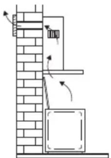
Extraction systems
Depending on the type, the cooker hoods can be connected in one of two ways:
- To a duct.
The cooking vapours extracted by suction are carried outside, once the grease particles have been filtered. This is the best method.
- Recirculation hood. When the hood is connected as a recirculation hood, the grease particles and odour in the extracted vapours are filtered.
The extracted air is not carried outside but recirculates in the kitchen. In this case you must have a carbon filter fitted.

Attention! The carbon filter needs to be ordered separately.
natural_image
Diagram of a staircase with brick wall and hanging door, showing airflow direction (no text or symbols)
natural_image
Diagram of a vertical structure with brick wall and cabinet, showing airflow direction (no text or symbols)Controls

text_image
1 2 3 4Switching fan on and off
Press the speed button 2, 3 or 4
The extractor hood switches on in the corresponding position.
Press the off button (2).
The fan will switch off.
Switching lighting on and off
Press the lighting button (1).
The lighting switches on.
Press the lighting button (1) again.
The lighting switches off.
Cleaning

Attention! Before performing any maintenance operation, isolate the hood from the electrical supply by unplugging the appliance or switching off your household's master switch. The cooker hood should be cleaned regularly (at least as frequently as the grease filters are cleaned) both internally and externally. Do not use abrasive products.
Do not use alcohol!
Attention! Failure to comply with the basic recommendations for cleaning the cooker hood and cleaning/replacing the filters may lead to a fire. Therefore, we recommend that you observe these instructions. The manufacturer declines all responsibility for any damage to the motor or any fire damage linked to inappropriate maintenance or failure to observe the above safety recommendations.
Cooker hood
Clean the cooker hood with soapy water and a soft cloth. Then wipe with clean water to rinse. Do not apply aggressive cleaning agents such as caustic soda. The paintwork on the cooker hood will remain shiny if it is periodically rubbed with wax.

Stainless steel canopy hoods
Do not use any sort of scourer. Treat with a stainless steel care product and polish with the structure of the stainless steel.
Metal grease filters
These must be cleaned once a month (or when indicated by the filter saturation indication system, if present on your model) using non-aggressive detergents, either by hand or in the dishwasher, which must be set to a low temperature and a short cycle. The openings must be placed downwards to let the water run out of the filters. When washed in a dishwasher, aluminium grease filters may be discoloured slightly. This is normal and does not affect their filtering capacity.
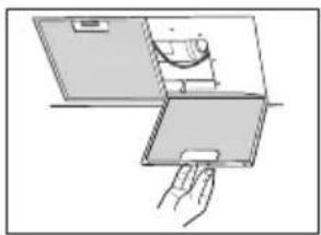
Grease filters
natural_image
Illustration of a hand holding a small object over a folded panel or tray (no text or symbols visible)Removing the grease filters
Switch off the electricity! Remove the plug from the mains socket or turn the switch in the meter cupboard to zero. Pull the grease filter towards you and tilt it forwards and down.
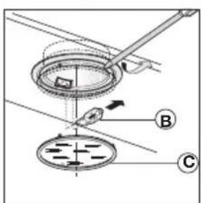
Carbon filter

text_image
OK!Replacing the carbon filter
The carbon filter must always be used if the cooker hood is not ducted.
- Remove the grease filters.
- Attach the carbon filters to the filter.
- Replace the grease filters.
Note:
- Saturation of the activated charcoal will eventually occur after prolonged use, depending on the type of cooking and how frequently the grease filter is cleaned.
- The carbon filter needs to be replaced at least every four months.
- The carbon filter cannot be washed for reuse. Saturated carbon is not environmentally friendly. Change the filter regularly.
Lighting

text_image
Technical diagram showing a mechanical assembly with labeled components A, B, and C, including a tool and directional arrows.Changing the light bulbs
- Remove the lamp cover.
- Replace the halogen light bulb with a replacement bulb with a maximum output power of 20 Watts.
- Re-close the lamp cover.
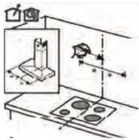
General
This appliance must be connected to the electric mains by an authorised installer who is familiar with the safety precautions and will carry them out. The appliance is in compliance with European guidelines.
Important information:
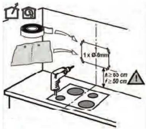
- The distance between the lowest point of the cooker hood and a gas hob must be at least 65 cm. If using an electric, ceramic or induction hob, this distance must be at least 50 cm.
- If the cooker hood is connected to an existing exhaust duct, no other appliance must be connected to the duct (such as a hot water heater or a stove).
- Consider local regulations with respect to the ventilation of gas appliances.
- The shorter the duct, and the fewer bends in it, the better the cooker hood will work.
- Check before you start drilling that no installation pipe(s) is/are present.
- The connection pipe to the cooker hood has a diameter of 120, 125 or 150 mm. We recommend that the exhaust pipe has as large a diameter as possible.
- The enclosed installation materials are suitable for reinforced concrete and brick walls. For some types of wall you may need special plugs and screws.
Connection
Electric connection
The appliance has been manufactured as a class I. The cable must be connected to an earthed socket!
Make sure the supply voltage ratings correspond with those stated on the appliance data plate. The connection to the mains is carried out as follows:
$$ B R O W N = \text { phase } L $$
$$ \text { BLUE } = \text { phase N } $$
$$ \text { YELLOW / GREEN } = \text { earth } $$
This canopy hood has been provided with a power plug. When installing the hood, make sure that this plug remains accessible. We recommend installing the wall socket out of view, behind the chimney cover.
Attention!
If you are making a fixed connection, you must ensure that a double pole switch with an air gap of at least 3 mm is fitted in the supply line.
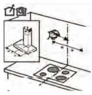
max 150 cm

text_image
Diagram showing a device with labeled components and signal paths, including a sensor or indicator on the top.Mounting

text_image
Technical diagram showing a mechanical assembly with labeled components and motion indicators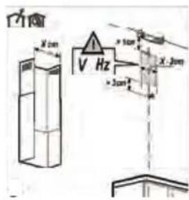
text_image
V X 1cm V Hz X 2cm > 3cm- Place a screw in the middle of the hood so that it hangs at the correct height.
text_image
1 x Ø 6mm ≥ 65 cm ≥ 50 cm- Place the mounting bracket of the top tube on the wall against the ceiling.

text_image
Diagram illustrating a mechanical or electrical setup with a device and directional arrows indicating motion or force.
natural_image
Technical line drawing of a mechanical device with exploded view and internal components (no text or symbols)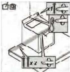
text_image
Technical diagram showing mechanical assembly with labeled components x1 and x2, including directional arrows and dimension lines.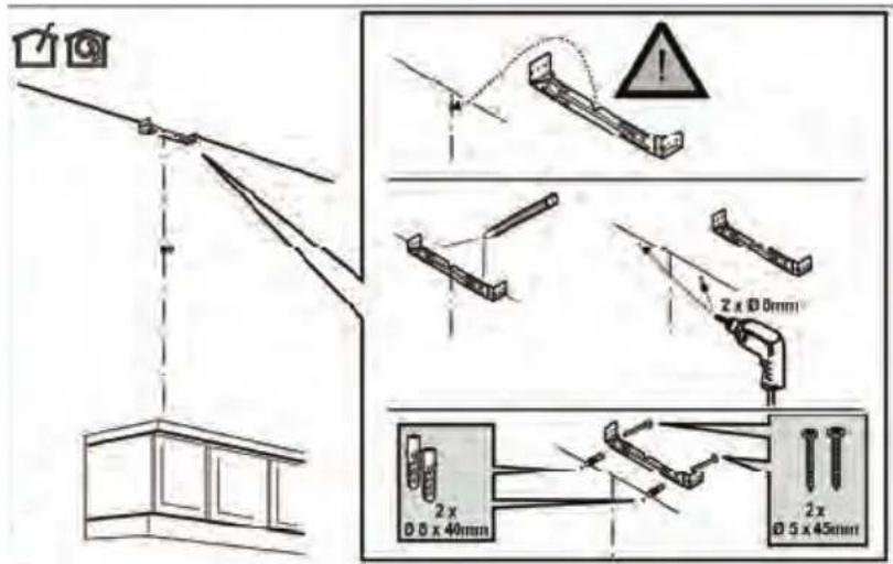
text_image
Diagram illustrating cable installation and wire repair process with labeled dimensions and warning symbols- Align the hood by using a spirit level and adjusting screws.
- Then screw the hood on the wall with plugs and screws.
Mounting
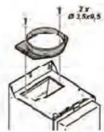
text_image
2x Ø3.5x0.5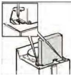
natural_image
Diagram showing a mechanical setup with an inset close-up of a tool interacting with a component (no text or symbols visible)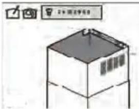
text_image
Diagram of a refrigerator with labeled buttons and a 3D model view- Insert the flange and place the electrical unit upright. Insert the plug into the wall socket. Ensure that the wall socket is not live!
- Connect the discharge pipe.
- Insert the upper tube into the lower tube..
- Let the tubes sink into the hood.
- Fold the top tube around the wall bracket and screw it onto the mounting bracket with screws.
Disposal
Disposal of appliance and packaging
This appliance was manufactured using sustainable materials. It must be disposed of responsibly at the end of its life cycle. The local authorities can provide you with the relevant information.
The packaging of this appliance is recyclable. It may have been made from:
- cardboard;
• polythene film (PE);
• CFRP-free polystyrene (PS hard foam).
You need to dispose of these materials responsibly in accordance with official regulations.

text_image
Warning symbol for a trash bin with crossed and unshaded lines indicating no waste or dischargeTo draw attention to the fact that the segregated processing of household electrical appliances is compulsory, this appliance carries the symbol of a crossed-out dustbin. This means that you may not dispose of the appliance as household refuse at the end of its useful life. Instead, it should be taken to a special segregated refuse collection centre run by the local authority or to a dealer providing this service.
Segregated processing of household appliances prevents any negative impact on the environment and public health that might otherwise arise. It allows the recovery of the materials used to manufacture this appliance, thus generating considerable savings in terms of raw materials and energy.
CE
Declaration of conformity
We declare that our products meet the applicable European Directives, Decisions and Regulations and the requirements listed in the standards referenced.