CRM1024 FCO-1006 - Compressor Ferm - Free user manual and instructions
Find the device manual for free CRM1024 FCO-1006 Ferm in PDF.

User questions about CRM1024 FCO-1006 Ferm
0 question about this device. Answer the ones you know or ask your own.
Ask a new question about this device
Download the instructions for your Compressor in PDF format for free! Find your manual CRM1024 FCO-1006 - Ferm and take your electronic device back in hand. On this page are published all the documents necessary for the use of your device. CRM1024 FCO-1006 by Ferm.
USER MANUAL CRM1024 FCO-1006 Ferm
GB Subject to change
D Ä n d e r u n g e n v o r b e h a l
natural_image
Illustration showing a person handling a box and a cylindrical device with internal components, labeled 1 and 2 (no text or symbols present)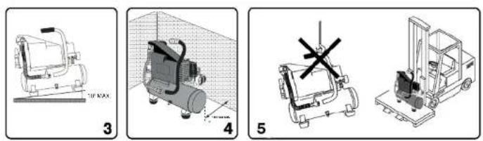
text_image
Technical diagrams showing four different mechanical or industrial setups with labeled components and annotations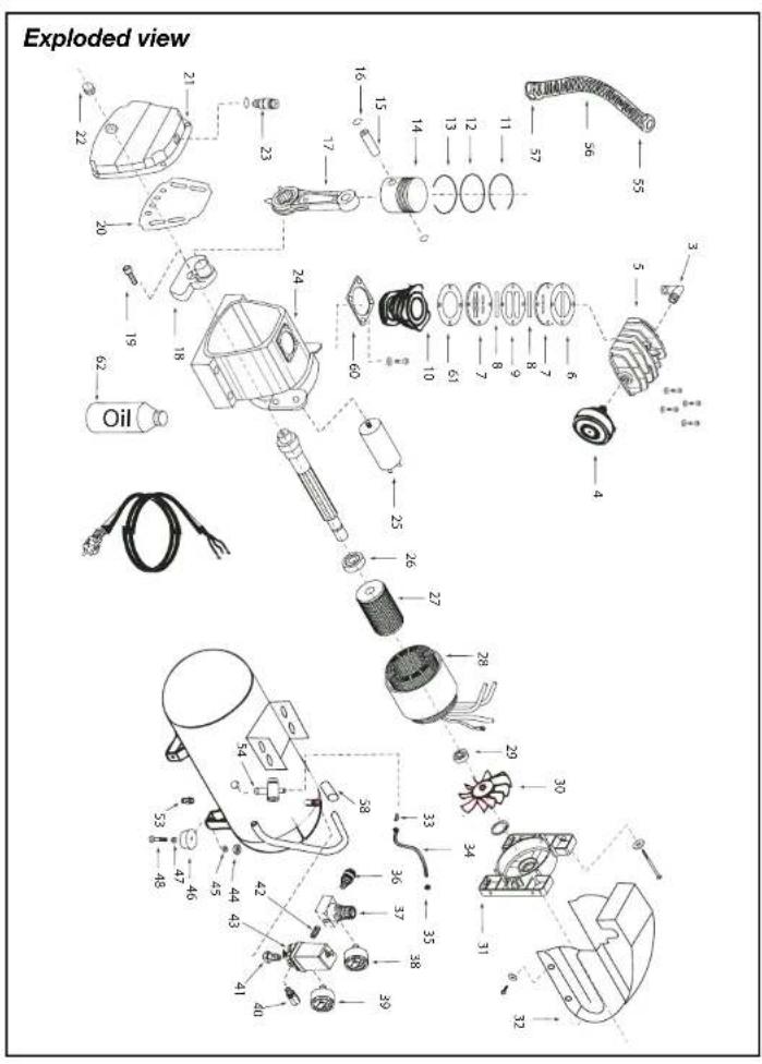
text_image
Exploded view OilSpare parts list FCO-1006
Ferm no. Description Position no.
| 700575 Knee coupling 3 | ||
| 700576 Air filter 4 | ||
| 700577 Cylinderhead 5 | ||
| 700563 Gasket set 6,9,60,61 | ||
| 700449 Valve assembly 7(2x),8(2x),9 | ||
| 700564 Cylinder 10 | ||
| 700565 Pistonrings (set) 11 till 13 | ||
| 700566 Piston complete 14,15,16(2x) | ||
| 700567 Connecting rod | 17 | |
| 700570 Crank | 18 | |
| 700568 Carter gasket 20 | ||
| 700569 Carter cover | 21 | |
| 700475 Oil level indicator | 22 | |
| 700578 Oil filling cap | 23 | |
| 800025 Capacitor 25 uf | 25 | |
| 806203 Bearing 6203 zz | 26 | |
| 700572 Stator | 28 | |
| 806004 Bearing 6004 zz | 29 | |
| 700579 Fan | 30 | |
| 700451 Plastic cover | 32 | |
| 700574 Unloading pipe | 33 till 35 | |
| 205254 Quick coupler | 36 | |
| 208029 Reduce valve | 37 | |
| 700454 Reduce valve + manometer | 36,37,38,42 | |
| CRA1005 Manometer 1/8" back | 38 | |
| CRA1003 Manometer 1/4" backside | 39 | |
| 205915 Safety valve 1/4 | 40 | |
| 700478 Connector auto-switch | 41 | |
| 205200 Double coupling 1/4' | 42 | |
| 700455 Automatic pressure switch | 43 | |
| 700458 Rubber foot | 44 till 48 | |
| 205888 Drain tap 1/4' | 53 | |
| 700580 Non-return valve | 54 | |
| 700581 Handle cover | 58 | |
| 700489 Bottle with oil (250ml) | 62 | |


COMPRESSOR OIL-BASED FCO-1006
The numbers in the following text correspond with the pitcures at page 2 - 3.

Carefully read this manual before using the machine. Make sure that you know how the machine functions and how to operate it. Maintain the machine in accordance with the instructions to make sure it functions properly. Keep this manual and the enclosed documentation with the machine.
Contents
- Machine details
- Safety instructions
- Use
- Faults
- Maintenance
1. MACHINE DETAILS
Technical specifications
| Voltage 230 V–Frequency 50 HzPower 1.0 HP / 750 WIdling speed 2850/minIP Class IP 33Tank contents 6.0 litre | |
| Air intake | 124 l/min |
| Max. outlet pressure | 8.0 Bar |
| Weight | 16.0 kg |
| Sound power level | 95.0 dB (A) |
The value of the noise level may rise from 1 to 10 dB(A) as a function of the environment in which the compressor will be installed.
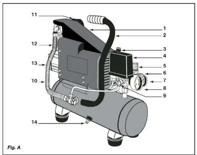
Product information
Fig. 1
1 Cover
2. Handle
3. Switch
4. Automatic stop
5. Pressure regulator
6. Quick coupler (outlet)
7. Pressure gauge (pressure regulator)
8. Pressure gauge (tank)
9. Safety valve
10. Pressure pipe
- Air filter
- Oil cap
- Sump
- Drain cock
2.SAFETY INSTRUCTIONS
Explanation of symbols
The following symbols are used in these instructions for use:

Read the instructions.

In accordance with essential applicable safety standards of European directives.

Denotes risk of personal injury, loss of life or damage to the tool in case of non-observance of the instructions in this manual.

Risk of electric shock.

Remove the plug from the mains

Attention: the compressor could start automatically in case of a black-out and subsequent reset

Caution: the compressor contains some parts which might reach high temperatures

Wear ear protection.

Sound power level

Faulty and/or discarded electrical or electronic apparatus have to be collected at the appropriate recycling locations.
Special safety instructions
- For proper operation of pressure, please make sure that the temperature of the working environment in an enclosed area is not more than +25°C.
- It is recommended to us under full load, to allow for proper operation of the product over time.
| • Check that the tank is f unscrewed. |
| • It is prohibited to make holes in, or welds to, o tank. |
| • Do not perform any actions on normer eller normative dokumenter: essor with the plug socket. |
| • Do not aim water jets or jets o EN1021-1, EN60204-1, EN60335-1 |
| • Do not place flammable objects near the compres s w it m mable liquid |
| • Switch the pressure regulator i overstemmelse med direktyeme: position |
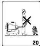
| • Never aim the air jet at persons or animals ( fig. |
| • Do not transport the compressors 98/37/EOF, 73/23/EOF, 89/336/EOF, 87/404/EOF, tank pr |
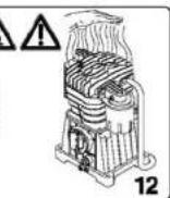
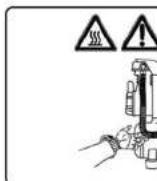
| • N . B . : some parts of the compressor such as the h reach high temperatures. Do not touch these parts to avoid burns (fig. 12-13). |
| • Transport the compressor ZWOLLE NL lifting it or by us ir |
| • Children and animals should be kept far away fro |
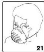
| • If you use the compressor to spray paint: |
| a) Do not work in enclosed spaces or near naked flames. |
| b) Make sure that the environment in which you will be working has dedicated ventilation. |
| c) Protect your nose and mouth with a dedicated mask (fig. 21). |
| • Do not use the compressor W. Kamphof when the electrical ca an authorised Support Service to replace them with an original part. |
| • When the compressor is placed on a surface high e prevent it from falling down during operation. |
| • Do not put objects or your products specificationne under forudgende varsel t damage to the compressor. |
| • Do not use the compressor Ferm BV • Lingenstraat 6 • 8028 PM Zwolle • Holland order to prevent serious damage. |
| • If the compressor is no longer in use, always t |
| • Always make sure that compressed - air hoses are |
Electrical safety
Earthing regulations
This compressor has to be earthed while in use in order to protect the operator against electrical shocks. The compressor is provided with a two-core cable plus an earth. The electrical connection has to be made by a qualified technician. We recommend never disassembling the compressor and neither making any other connections into the pressure regulator. Repairs should be carried out by authorised Support Services or by other qualified centres.

Never forget that the earthing core is the green or the yellow/green wire. Never connect this green wire to a terminal under load.
Before replacing the plug of the feed, make sure that the earth cable is connected. If in doubt, please call in a qualified electrician and have the earthing checked.
CE KONFORMITETSERKLÆRING (DK)
[Non-Text]
[Non-Text]
[Non-Text]
[Non-Text]
[Non-Text]
[Non-Text]
[Non-Text]
[Non-Text]
[Non-Text]
[Non-Text]
[Non-Text]
[Non-Text]
[Non-Text]
[Non-Text]
[Non-Text]
[Non-Text]
[Non-Text]
[Non-Text]
[Non-Text]
[Non-Text]
- F y l d o l i e p â v i a d e t ø v e Extension cables h u l p â b e h o l d e r l â g
Only use an extension cable with a plug and earth, so never use damaged or flattened extension cables. Check whether the extension cable is in a good condition. For this device the extension cable should have a diameter of at least 2.5 m (this applies to a maximum length of 20 metres). Always unroll extension cables fully before using them.
Electrical connection
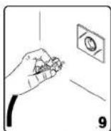
Always check whether the input voltage of the motor corresponds to the mains voltage indicated on the specification plate. The compressors are supplied with an electrical cable and a two-pole plug + earth. It is important to connect the compressor with an earthed plug socket. (fig. 9)

Never use the earth-wire instead of the neutral (0-wire). The earthing should take place in accordance with accident prevention regulations (EN 60204).
3. USE

For homehold use only
NB: The information you will find in this manual has been written to assist the operator in the use and maintenance of the compressor. Some illustrations in this manual show details which may differ from those of your compressor.
Installation
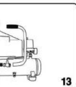
After having taken the compressor out of its packaging (fig. 1) and having checked that it is in perfect condition, and having noted that no damage occurred during transport, the following acts should be performed. If not yet fitted, fit the rubber feet on the tank according to the instructions represented in fig. 2. Place the compressor on a flat surface or at a maximum slope of 10^ (fig.3), in a well ventilated area, protected against atmospheric factors and not in explosive surroundings. If the surface area is sloping and smooth, make sure that the compressor will not move when in operation. If the surface area is a board or a shelf of a bookcase, just make sure that they cannot fall down by securing them properly. For proper ventilation and effective cooling, it is important that the compressor is positioned at least 100 cm from the wall (fig. 4).

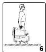
Make sure that the compressor is transported in the right way, do not turn it upside down and don't lift it with hooks or ropes (fig. 5-6).
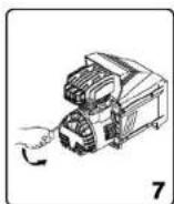
Important! Before commissioning
Remove the plastic cap from the sump lid. Fill the sump with the oil supplied. The gauge at the bottom of the sump indicates the oil level: this should now be level with the red dot (fig. 7 and 8).
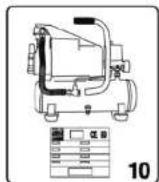
Starting up
- Check whether the main specification plate (fig. 10), the permitted tolerance range should be within 5% .
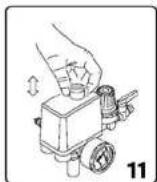
- Press the switch situation regulator type fitted on the device (fig. 11).
- Put the plug in the plug the pressure regulator in the "I" position. The operation of the compressor is fully automatic. The pressure regulator will stop the compressor when the maximum value has been reached and start it up when the pressure drops below the minimum value. Normally the difference in pressure is approx. 2 Bar/29 psi between the maximum and the minimum value. For instance - The compressor will stop when it reaches 8 Bar (116 psi) (this is the maximum operating pressure) and will start up automatically when the pressure within the tank has dropped to 6 Bar (87 psi).

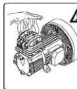
The head/cylinder/transmission pipe assembly may reach high temperatures, so take care when working close to these parts and do not touch them to avoid burns (fig. 12 - 13).
Adjusting the operating pressure
Fig. 14
It is not necessary continuously to use the maximum operating pressure, the compressed-air tools often require less pressure. With regard to compressors supplied with a pressure reduction valve it is necessary to set the operating pressure properly. It is possible to set the operating pressure by using the turning knob on the reduction valve.
| • B y | t u r n i n g | c l o c k w i s e , t h |
| • B y | t u r n i n g | a n t i - c l o c k w i s |
The set pressure can be locked by turning the ring under the turning knob in the opposite direction from the turning knob thereby fixing the turning knob. The set pressure is visible on the manometer of the reduction valve.
4.FAULTS
Air loss
| • | M | a | y | b | e | c | a | u | s | e | d | b | y | a | p | o | o | r | |||||
| • | C | h | e | c | k | a | l | l | c | o | n | n | e | c | t | i | o | n | s |
The compressor runs but does not compress
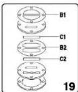
Fig. 19
| • | M | a | y | b | e | c | a | u | s | e | d | b | y | t | h | e | v | a | |||||
| • | R | e | p | l | a | c | e | t | h | e | d | a | m | a | g | e | d | p | a |
The compressor will not start
If the compressor is difficult to start, check:
| • whether the voltage of |
The compressor does not shut off
If the compressor does not shut off when the maximum pressure has been reached, the safety valve of the tank will be activated. It is necessary to contact the nearest authorised Support Service for the repair.
5.MAINTENANCE
Maintenance

Make sure that the plug is removed from the mains when carrying out maintenance work on the motor.
| The Ferm machines have been designed to operate over a long period of time with a minimum of maintenance. Continuous satisfactory operation depends upon proper machine care and u_regular clearing . Before interfering in any way whatsoever with the compressor, please make u_sure that: : t , v i l l t r y k k e t m j n d s k e |
| • T h e g e n e r a l l i n e s w i t c h |
| • T h e p r e s s u r e r e g u l a t o r position. |
| • T h e a i r t a n k i s f u l l y d e |
Cleaning
Regularly clean the machine housing with a soft cloth, preferably after each use. Keep the ventilation slots free from dust and dirt.
If the dirt does not come off use a soft cloth moistenediwith soapy water. Never use solvents such as petrol alcohol, ammonia water, etc. These solvents may damage the plastic parts
Lubrication
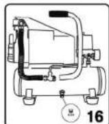
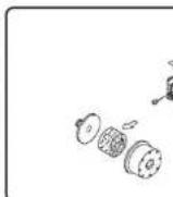
| It is recommended to disassemble the suction filter every 50 operating hours and to clean the filter element by blowing it with compressed air (fig. 15). It is recommended that the filter element is replaced at least once a year if the compressor is working in a clean environment; more often if the environment in which the compressor is situated is dusty. The compressor makes condensed water which collects in the tank. It is necessary to remove the condensed water in the tank at least once a week by opening the drain cock (fig. 16) under the tank. Take n care when compressed air is in the bottle because the water can come out with some force. A Recordmended pressure max. 1-2 Bar.a n v end e s m e d e r k o l d t (under 0 °C). |
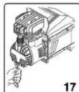
Replacing/topping up oil
The compressor has been supplied with synthetic oil "SAE 10W30". It is recommend to fully replace the oil of the pump system within the first 100 operating hours.
| • U n s c r e w t h e d r a i n p l u g plug (fig. 17). |
| • F i l l t h e o i l v i a t h e u p (fig. 8) has been reached. |
Check the oil level of the pump system every week and if necessary top up. For operation under ambient temperatures of -5^ to +35^ use synthetic oil “SAE 10W30”. The synthetic oil has the advantage that it does not lose its characteristics, either in summer or in winter periods.

You should not dispose of the used oil in the sewer or in the environment.
For replacement of oil the table below should be adhered to.
Oil type Operating hours
Multigrade oil SAE 10W30 100 or 6 months
Faults
Should a fault occur, e.g. after wear of a part, please contact the service address on the warranty card. In the back of this manual you find an exploded view showing the parts that can be ordered.
Environment
To prevent damage during transport, the appliance is delivered in a solid packaging which
consists largely of reusable material. Therefore please make use of options for recycling the packaging.

Faulty and/or discarded electrical or electronic apparatus have to be collected at the appropriate recycling locations.
Warranty
The warranty conditions can be found on the separately enclosed warranty card.
CE DECLARATION OF CONFORMITY (GB)
f t s t a n k e n u d e n a t t a g e s
We declare under our sole responsibility that this product conforms with the following
e r i a l e r standardspr standardised documents: n a f k o m
p o s i t i o n EN1021-1, EN60204-1, EN60335-1
s s o r e n m e d e n t a n k u n d e r
or de le s in accordance with regulations: e d e t o q r
98/37/EEC,73/23/EEC,89/336/EEC,87/404/EEC,2000/14/EEC
-
-
-
-
-
-
-
-
-
-
-
-
-
-
-
-
-
-
-
-
-
-
-
-
-
-
-
-
-
-
-
-
-
-
-
-
-
-
-
-
-
-
-
-
-
-
-
-
-
-
-
-
-
-
-
-
-
-
-
-
-
-
-
-
-
-
-
-
-
-
-
-
-
-
-
-
-
-
-
-
-
-
-
-
-
-
-
-
-
-
-
-
-
-
-
-
-
- 99.
-
-
-
-
-
-
-
-
-
-
-
-
-
-
-
-
-
-
-
-
-
-
-
-
-
-
-
-
-
-
-
-
-
-
-
-
-
-
-
-
-
-
-
-
-
-
-
-
-
-
-
-
-
-
-
-
-
-
-
-
-
-
-
-
-
-
-
-
-
-
-
-
-
-
-
-
-
-
-
-
-
-
-
-
-
-
-
-
-
-
-
-
-
-
-
-
from 01-01-2006 n g a f s t a n d a f m a s k i n
ZWOLLE NL e n t i l s p r a y - m a l i n g
c e r e t p ä e n o v e r f l a d e h ø j
W. Kamphot
Quality department e h æ n d e r i n d i d e b
g e s k a d e r b ø r A n v e n d i k k
It is our policy to continuously improve our products and we therefore reserve the right to
s change the product specification without prior notice; h v i s k o m p
f t s s l a n g e r e r a n v e n d t t i l
Ferm BV • Lingenstraat 6 • 8028 PM Zwolle • The Netherlands
Elektrisk sikkerhed
Regler ang. jordforbindelse
Denne kompressor skal have en jordforbindelse for at beskytte brugeren mod elektriskchok.
CE ERKLÆRING AV ANSVARSFORHOLD (N)
98/37/ETY, 73/23/ETY, 89/336/ETY, 87/404/ETY
Voimassa 01-01-2006
ZWOLLE NL
W. Kamphof
Laadunvalvontaosasto
CE DÉCLARATION DE CONFORMITÉ (F)
98/37/CEE, 73/23/CEE, 89/336/CEE, 87/404/EEC
dès 01-01-2006
ZWOLLE NL
W. Kamphof
Quality department
| No. | A | B | C | D | E |
| 1 | 0 | 0 | 0 | 0 | 0 |
98/37/CEE, 73/23/CEE, 89/336/CEE, 87/404/EEC
del 01-01-2006
ZWOLLE NL

W. Kamphof
Quality department
natural_image
Black FERM air compressor device with attached piping and control panel (no visible text or symbols on body)H HASZNÁLATI UTASÍTÁS 04
CZ NÁVOD K POUŽITI 12
SI NOVODILA ZA UPORABO 20
PL INSTRUKSJE OBSŁUGI 28
RUS РУКОВОДСТВО ПО ЭКСПЛУАТАЦИИ 36
GR OΔΗΓΙΕΣ ΧΡΗΣΕΩΣ 44


www.ferm.com
text_image
1 2 3 4 5 6 7 8 9 10 11 12 13 14 Fig. A
natural_image
Illustration showing a person handling a box and a cylindrical device with internal components, labeled 1 and 2 (no text or symbols present)
text_image
Technical diagrams showing four different mechanical or industrial setups with labeled components and directional indicators.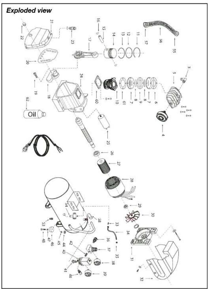
text_image
Exploded view 21 22 23 24 25 26 27 28 29 30 31 32 33 34 35 36 37 38 39 40 41 42 43 44 45 46 47 48 49 50 51 52 53 54 55 56 57 58 59 60 61 62 63 64 65 66 67 68 69 70 71 72 73 74 75 76 77 78 79 80 81 82 83 84 85 86 87 88 89 90 91 92 93 94 95 96 97 98 99 100Spare parts list FCO-1006
Ferm no. Description Position no.
| 700575 Knee coupling 3 | ||
| 700576 Air filter 4 | ||
| 700577 Cylinderhead 5 | ||
| 700563 Gasket set 6,9,60,61 | ||
| 700449 Valve assembly 7(2x),8(2x),9 | ||
| 700564 Cylinder 10 | ||
| 700565 Pistonrings (set) 11 till 13 | ||
| 700566 Piston complete 14,15,16(2x) | ||
| 700567 Connecting rod | 17 | |
| 700570 Crank | 18 | |
| 700568 Carter gasket 20 | ||
| 700569 Carter cover | 21 | |
| 700475 Oil level indicator | 22 | |
| 700578 Oil filling cap | 23 | |
| 800025 Capacitor 25 uf | 25 | |
| 806203 Bearing 6203 zz | 26 | |
| 700572 Stator | 28 | |
| 806004 Bearing 6004 zz | 29 | |
| 700579 Fan | 30 | |
| 700451 Plastic cover | 32 | |
| 700574 Unloading pipe | 33 till 35 | |
| 205254 Quick coupler | 36 | |
| 208029 Reduce valve | 37 | |
| 700454 Reduce valve + manometer | 36,37,38,42 | |
| CRA1005 Manometer 1/8" back | 38 | |
| CRA1003 Manometer 1/4" backside | 39 | |
| 205915 Safety valve 1/4 | 40 | |
| 700478 Connector auto-switch | 41 | |
| 205200 Double coupling 1/4' | 42 | |
| 700455 Automatic pressure switch | 43 | |
| 700458 Rubber foot | 44 till 48 | |
| 205888 Drain tap 1/4' | 53 | |
| 700580 Non-return valve | 54 | |
| 700581 Handle cover | 58 | |
| 700489 Bottle with oil (250ml) | 62 | |