CRM1008 FC 730 - Compressor Ferm - Free user manual and instructions
Find the device manual for free CRM1008 FC 730 Ferm in PDF.

User questions about CRM1008 FC 730 Ferm
0 question about this device. Answer the ones you know or ask your own.
Ask a new question about this device
Download the instructions for your Compressor in PDF format for free! Find your manual CRM1008 FC 730 - Ferm and take your electronic device back in hand. On this page are published all the documents necessary for the use of your device. CRM1008 FC 730 by Ferm.
USER MANUAL CRM1008 FC 730 Ferm
UK Subject to change
text_image
Technical diagram of an industrial machine with numbered components for identificationFig. A
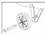

Fig. B Fig. C
text_image
Technical diagram of a portable air purifier with numbered components and labeled partsFig. D

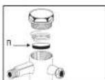
Fig. E Fig. F
text_image
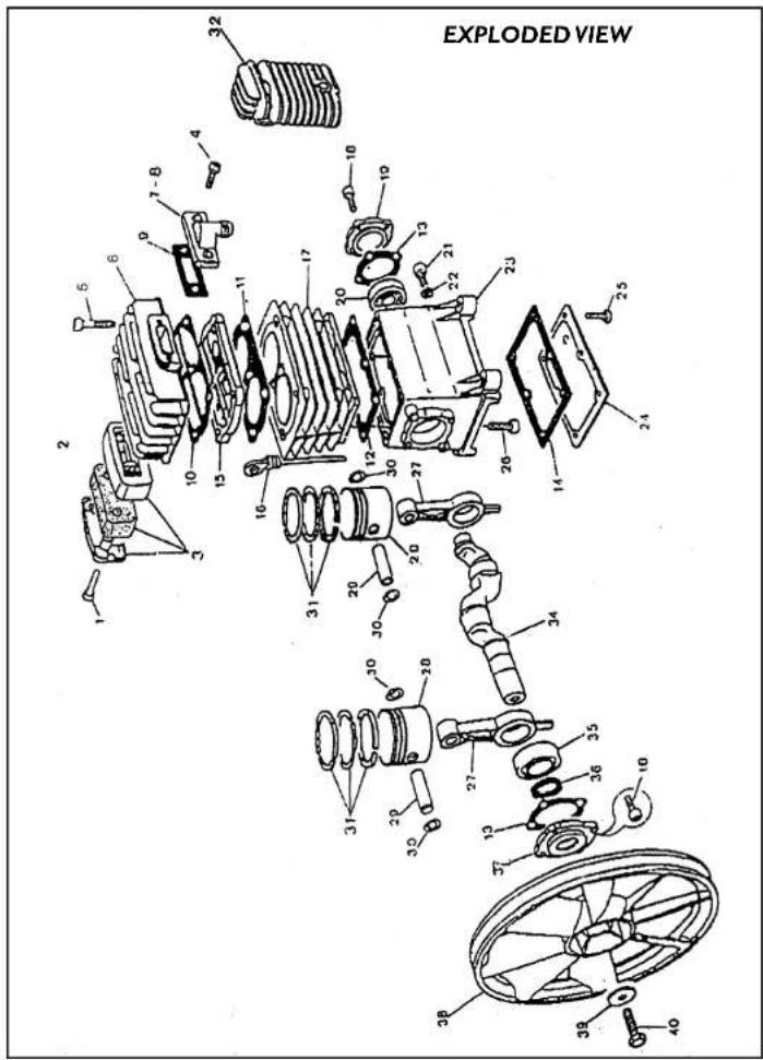
EXPLODED VIEW2 Ferm Ferm 39
SPARE PARTS LIST
| REF.NR.DESCRIPTION FERM NR. | ||
| MOTOR, 2250W - 400V 206003 | ||
| RILSAN TUBE 4/6 208249 | ||
| PACKING SET 208231 | ||
| 3 | AIR FILTER 9COMPLETE0 | 208232 |
| 6 | CYLINDER HEAD | 208233 |
| 8 | CONNECTION PRESS TUBE | 208234 |
| 9 | PACKING | 208390 |
| 10 | CYLINDER HEAD PACKING | 208236 |
| 11 | VALVE PLATE PACKING | 208237 |
| 12 | CYLINDER PACKING | 208238 |
| 13 | PACKING | 208239 |
| 14 | PACKING | 208240 |
| 15 | VALVE PLATE | 208241 |
| 16 | OIL LEVEL | 208242 |
| 27 | CONNECTION ROD | 208243 |
| 28 | PISTON | 208244 |
| 29 | PISTON PIN | 208245 |
| 31 | PISTON RING SET | 208246 |
| 34 | CRANK SHAFT | 208247 |
| 38 | FLYWHEEL | 208248 |

FC-730COMPRESSOR
THE NUMBERS IN THE FOLLOWING TEXT COR-
RESPOND WITH THE PICTURES AT PAGE 2
TECHNICAL SPECIFICATIONS
Voltage|230V
Frequency | 50 Hz
Power input|2200W
No load speed | 2880/min.
Pumpcapacity | 326 l/min.
Weight 86 kg.
Lpa (sound pressure) | 77 dB(A)
This is a V-Belt driven 2-cylinder compressor in mobile design. This compressor is also equipped with a reducing valve, a automatic shutdown and a quick coupling.
SAFETY INSTRUCTIONS
The following pictograms are used in these instructions for use:

Denotes risk of personal injury, loss of life or
damage to the tool in case of non-observance of the as in this manual.

Denotes risk of electric shock.
Carefully read this manual before using the machine. Make sure that you know how the machine functions and how to operate it. Maintain the machine in accordance with the instructions to make sure it functions properly. Keep this manual and the enclosed documentation with the machine.
When using electric machines always observe the safety regulations applicable in your country to reduce the risk of fire, electric shock and personal injury. Read the following safety instructions and also the enclosed safety instructions.
Keep these instructions in a safe place!
ADDITIONAL SAFETY INSTRUCTIONS
- The air compressor must be used in a suitable environment (good ventilation - within ambient temperature +5°C - +40°C). The area in which the compressor is operated must be free from dust, acids, vapour, explosive gas, flammable or unstable materials.
• To obtain sufficient ventilation and cooling the distance between the shield and the wall needs to be at least 50 to 60 cm.
- Do not leave the machine outside where it can be affected by the weather.
- Keep a safety distance between the compressor and the working area specially in using paints or liquids goods. External possible colourings of the compressor show enough distance.
- Do not weld or make any modifications whatsoever to the tank. If you find some defects, air leak or corrosion the unit must be returned to the Service Centres for a replacement to be fitted.
- Never aim compressed air towards people or towards your body and remember that the use of protective glasses is necessary for protecting the eyes from dust and other particles moved by compressed air
- The use of compressed air in its applications (tyre inflation, pneumatic tools, spray painting, washing, detergent washing etc.) must comply with the relevant regulations for the individual cases guaranteeing the minimum distance of 6 meters between the working area and the compressor.
- Compressed air from a compressor cannot be used for pharmaceutical, food or health uses without further treatment.
- Do not use the compressed air to fill the cylinders for breathing/diving apparatus.
THE FOLLOWING POINTS NEED TO BE CHECKED:
- Do the voltage of the engine and the engine safe guard, if any, correspond to the mains voltage;
- An earthed mains connection (wall socket) needs to be used;
- Are the mains lead and the mains plug in a good condition: solid, without any loose ends or damage;
• The pressure reducing valve may not be completely closed so as to prevent damage to membranes:
• The oil level with help from the gauge. The oil level should be within the area indicated by both marks on the gauge, when the compressor is placed level.
• Before use the air tank needs to be empty.
To prevent damage to the motor windings as a result of voltage variation it is advisable to mount an engine safety switch.
IMMEDIATELY SWITCH OFF THE COMPRESSOR IN CASE OF:
- Defective mains plug, mains line or damage to the mains line;
• Defective switch;
• Smoke or bad smell caused by scorched insulation.
ELECTRICAL SAFETY
Always check that the power supply corresponds to the voltage on the rating plate.
Replacing cables or plugs
Immediately throw away old cables or plugs when they have been replaced by new ones. It is dangerous to insert the plug of a loose cable in the wall outlet.
Using extension cables
Only use an approved extension cable suitable for the power input of the machine. The minimum conductor size is 1.5 mm2. When using a cable reel always unwind the reel completely.
INSTALLATION
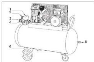
Fig. A
-
On/off switch
-
Reducing valve
-
Quick coupling
-
Manometer
-
Oil gauge
-
Draining valve
-
Airfilter
-
Quick coupling
STARTUP AND USE
Fig. B & C
• Assemble the wheels and components.
- Check oil level on the viewer (5) and eventually fill-in through the breather pipe. Level under the lower edge, is dangerous for the integrity of the pump and excess of oil will cause passing of oil in the compressed air.

Start and stop actions have to be made only
through the on-off switch (1), to stop the compres-
plug can cause grave damage to the electric motor in
tarting.
The compressor must be installed in a frost free well ventilated room. Position the unit at least 50 cm from any wall or obstruction to enable correct cooling. To ensure correct lubrication position the unit on a level surface.
OPERATION
- The mains switch (1) needs to be in "OFF" or "0" position before the mains plug is connected to the mains voltage.
- Bij switching the switch (1) to "ON" or "I" the com-
pressor will operate.
• Always keep the mains lead away from moving parts
of any linked up air-pressure equipment. - With the use of the reducing valve (2) it is possible to adjust the air pressure by hand.
PRESSUREADJUSTMENT
Fig. E

Air pressure switch (1) has already been set at the
test stage, do not change pressure valve (increase
re is dangerous for the motor.)
Keeping the tap (3) open the regulation knob pulling it up first and then rotate the regulation knob (2) clockwise to increase the pressure and anti-clockwise to reduce it, never exceed the max. set value having verified the requested value on the manometer (4). At the end of operation return to 0 bar.
On the tank there is if required a direct outlet (8) for max. pressure. The pressure of air supplied depends on the value of the set pressure and the excessive air consumption is shown by the low gauges values
MAINTENANCE
The mains plug always needs to be taken out of the socket (the mains socket) during maintenance, inspection or cleaning activities.
PERIODIC MAINTENANCE OF THE COMPRESSOR WILL PREVENT UNNECESSARY PROBLEMS!
FAULTS
Should a fault occur, e.g. after wear of a part, please contact your local Ferm dealer.
In the back of this manual you find an exploded view showing the parts that can be ordered.
POSSIBLE PROBLEMS AND REMEDIES
Fig. F
Air leaks through the pressure switch (1) when the compressor is stopped
• Non return valve worn or dirty not working properly
• Dismantle the non return valve head clean rubber disc (R) and/or replace it
• Reassemble with care.
Reduction in performance, starting too often or low pressure
If the demand on the air supply remains the same, check for air leaks on pipe and hoses, the conditions of the intake filter or belt-driven regulation.
- Replace the seals of the fittings-clean or change air intake cartridge.
• Recheck the regulation of belts
The motor or the pump overheats
Not enough cooling air on the motor or the pump.
- Check ambient temperature, oil level and quality, intake filter, proper voltage.
The compressor stops after trying to start or stops and will not start again
• The air tank is full. Improper voltage or lubrication
- Bad connection
- Check all parameter as before
• If the problem is not resolved contact the specialist service organisation
Anomal presence of oil in the compressed air.
• Excessive oil level.
• Wear of piston rings - Check oil level
• Ask for Assistance
CONDENSATION
Humidity of the air wich condenses in the tank must be drained, at least weekly through tap (6). If there is no oil in the condensed water than it may be drained without fear and pollution.
DRIVE BELTS TENSION
Drive belts require a precise tensioning of the belt because at low values there are slippings on the pulley causing overheating, and rapid wear of the belt. High values cause excessive load on the bearing causing fast wear of the same and motor over heating. The correct tension value is obtained pushing with a screwdriver on the intermediate area and you obtain a deflection of 1 cm.
OILLEVEL
The compressor comes with a special test oil, that must be Replaced after about 100 hours of use. Check the oil level from time to time, using the oil gauge.
When the compressor is level and has not been used for some time, the oil level should be within the area indicated by both marks on the gauge. The oil must be replaced after every 300 hours of use or at least once a year. Use compressor oil API CC SAE 40 rather than motor oil. If the compressor is used in temperatures below 0^ , use API CC SAE 20 oil.
EVERY MONTH
Clean the air filter
Every 300 working hours:
- Refresh the oil
- Carefully clean the outside of both the compressor and the engine, to ensure an efficient cooling.
Condensation
- Regularly, drain condensation from the air chamber, using the drain cock situated on the underneath of the air chamber.
Have your compressor repaired by an expert!
This electric appliance is in accordance with the relevant safety rules. Repairing of electric appliances may be carried out only by experts other wise it may cause considerable danger for the user.
ENVIRONMENT
In order to prevent the machine from damage during transport, it is delivered in a sturdy packaging. Most of the packaging materials can be recycled. Take these materials to the appropriate recycling locations. Take your unwanted machines to your local Ferm-dealer. Here they will be disposed of in an environmentally safe way.
GUARANTEE
The guarantee conditions can be found on the separately enclosed guarantee card.
CE DECLARATION OF CONFORMITY (UK)
We declare under our sole responsibility that this
product is in conformity with the following
standards or standardized documents
prEN1012-1, EN661, 29, EN292, ISO5388
EN55014-1, EN55014-2, EN61000-3-2, EN61000-3-3
in accordance with the regulations:
98/37/EEC
73/23EEC
89/336EEC
from 26-05-1998
GENEMUIDEN NL
G.M. Ensing
Quality department
D Deutsch
FC-730 KOMPRESSOR
- Keep a safety distance between the compressor and the working area specially in using paints or liquids goods. External possible colourings of the compressor show enough distance.
98/37/EEC 73/23EEC 89/336EEC
ab 03-02-2000 GENEMUIDEN NL G.M. Ensing Quality department
NL Nederlands
FC-730 COMPRESSOR
DE NUMMERS IN DE NU VOLGENDE TEKST VERWIJZEN NAAR DE AFBEELDINGEN OP PAGINA 2
TECHNISCHE GEGEVENS
CE DÉCLARATION DE CONFORMITÉ (F)
98/37/EEC 73/23EEC 89/336EEC
dès 01-04-1999 GENEMUIDEN NL G.M. Ensing Quality department

BESKRIVELSE
Fig. A
-
On/off trykkontakt
-
Trykregulator
-
Hurtigkobling
-
Hardigkobring
-
Tuvslufswälenon
-
Tryklufsmal
-
Oliocordtse
-
Ollestandup
-
Vandcap
-
Indgangsfilter
-
Hurtigkobling
OPSTART OGBETJENING
Fig. B & C
UPPSTART OCH HANDHAVANDE
Fig. B & C
98/37/EEC 73/23EEC 89/336EEC
03-02-2000
GENEMUIDEN NL G.M. Ensing Quality department

BRUGER
KÄYTTÖÖNOTTO
Fig. D
98/37/EEC 73/23EEC 89/336EEC