
WSC 55 - Saw HILTI - Free user manual and instructions
Find the device manual for free WSC 55 HILTI in PDF.


| Product Type | Manual Circular Saw |
| Brand | Hilti |
| Model | WSC 55 |
| Dimensions (L x W x H) | 340 mm x 265 mm x 269 mm |
| Weight (according to EPTA 01/2003) | 4.7 kg |
| Rated voltage | 220-230 V |
| Line frequency | 50-60 Hz |
| Power input | 1500 W |
| Rated current | 7.0 A (230 V) |
| No-load speed | 5500 rpm |
| Max. blade diameter | 160 mm |
| Arbor diameter | 20 mm |
| Cutting depth at 90° | 55 mm |
| Cutting depth at 45° | 40 mm |
| Cutting depth at 50° | 36 mm |
| Cutting angle range | 0° to 50° |
| Protection class | II (double insulation) |
| Power cable length | 4 m |
| Sound power level (A) | 105 dB(A) |
| Sound pressure level | 94 dB(A) |
| Vibrations (cutting wood) | < 2.5 m/s² (uncertainty 1.5 m/s²) |
| Protective guard | Pivoting with dust extraction hood |
| Parallel stop | Included (WPG 70/55) |
| Guide rail | Optional (WGS 1400-2B) |
| Cleaning | Clean ventilation slots with a dry brush; exterior with a damp cloth |
| Maintenance | Regularly check parts and replace if necessary; have repairs done by Hilti service center |
| Safety | Switch with lock-off device, pivoting guard, riving knife |
| Spare parts | Saw blades, flanges, dust extraction hood, brushes, etc. |
| Manufacturer's warranty | Free repair or replacement of defective parts during the service life |
Frequently Asked Questions - WSC 55 HILTI
User questions about WSC 55 HILTI
0 question about this device. Answer the ones you know or ask your own.
Ask a new question about this device
Download the instructions for your Saw in PDF format for free! Find your manual WSC 55 - HILTI and take your electronic device back in hand. On this page are published all the documents necessary for the use of your device. WSC 55 by HILTI.
USER MANUAL WSC 55 HILTI
natural_image
Red and black power tool with blade and fan assembly, displayed against solid red background (no visible text or symbols)1




8
natural_image
Diagram of a mechanical assembly with clamps and a wooden base, showing no text or symbols
WSC70/WSC55Hand-Kreissäge
Head of BA Quality and Process Management
Business Area Electric Tools & Accessories
01/2012
Jan Doongaji
Executive Vice President
Business Unit Power
Tools & Accessories
01/2012
WSC70/WSC55circularsaw
en
It is essential that the operating instruct are read before the power tool is open the first time.
Always keep these operating instructions get her with the power tool.
Ensure that the operating instructions a with the power tool when it is given persons.
Contents Page
| 1 General information 14 |
| 2 Description 15 |
| 3 Accessories 17 |
| 4 Technical data 17 |
| 5 Safety instructions 18 |
| 6 Operation 21 |
| 7 Care and maintenance 24 |
| 8 Troubleshooting 24 |
| 9 Disposal |
| 10 Manufacturer's warranty - tools |
| 11 EC declaration of conformity (original) |
1 These numbers refer to the corresponding illustrations. The illustrations can be found on the fold-out of pages. Keep these pages open while studying the operating instructions.
In these operating instructions, the designation “the power tool” always refers to the WSC 70 or WSC 55 Circular saw.
Components, operating controls and indicators 1 to-
① On / off switch
② Switch-on interlock
to③ Auxiliary grip other
④ Drive spindle lockbutton
⑤ Hexagon socket wrench
⑥ Cutting angle scale
⑦ Clamping lever for cutting angle adjustment
⑧ Clamping screws for the parallel guide
⑨ Clamping lever for cutting depth adjustment
⑩ 45°cutting line indicator
⑪ 0°cutting line indicator
⑫ Parallel guide (rip fence)
⑬ Pivoting guard
⑭ Riving knife
⑮ Base plate
216 Guard
⑰ Rotatable chip ejector
⑱ Drive spindle
⑲ Mounting flange
⑳ Clamping flange
21 Clamping screw
②2 Cutting depth scale
②3 Riving knife fastening screws
⑳ Pivoting guard operating lever
⑳ Chip deflector guard
②6 Chip deflector guard release
⑳ Angle extender for 50° cuts
1 General information
1.1 Safety notices and their meaning
DANGER
Draws attention to imminent danger that will lead to serious bodily injury or fatality.
WARNING
Draws attention to a potentially dangerous situation that could lead to serious personal injury or fatality.
CAUTION
Draws attention to a potentially dangerous situation that could lead to slight personal injury or damage to the equipment or other property.
NOTE
Draws attention to an instruction or other useful information.
1.2 Explanation of the pictograms and other information
Warning signs

General warning

Warning: electricity
Obligation signs

Wear eye protection

Wear a hard hat

Wear ear protection

Wear
protective
gloves

Wear
breathing
protection
Symbols

Read the operating instructions before use

Return waste material for recycling.


Volts Alternating current

Rated speed under no load
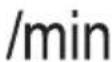
Revolutions per minute

Diameter Saw blade

Location of identification data on the power tool
The type designation and serial number can be found on the type identification plate on the machine or tool. Make a note of this data in your operating and always refer to it when making an enquiry to your Hilti representative or service department.
Type:
Serial no.:
en
2 Description
2.1 Use of the product as directed
The power tool is a hand-guided circular saw.
The power tool is designed for sawing wood or wood-like materials, plastics, drywall panel (plasterboard), gypsum fiberboard and composite materials with a thickness of up to 55 or 70 mm (depending on model) and for bevel cuts at angles between 0° and 50°.
Working on materials hazardous to the health (e.g. asbestos) is not permissible.
The power tool is designed for professional use and may be operated, serviced and maintained only by trained, authorized personnel. This personnel must be informed of any special hazards that may be encountered. The power tool and its ancillary equipment may present hazards when used incorrectly by untrained personnel or when used not as directed.
The working environment may be as follows: construction site, workshop, renovation, conversion or new construction. The power tool may be operated only when connected to a power supply providing a voltage and frequency in compliance with the information given on its type identification plate.
The use of saw blades that do not comply with the given specification (e.g. diameter, thickness) or the use of cutting and grinding discs or blades made from high-alloy steel (HSS steel) is not permissible.
Sawing metals is not permissible.
Do not use the power tool to cut tree branches or logs.
To avoid the risk of injury, use only genuine Hilti accessories and insert tools.
Observe the information printed in the operating instructions concerning operation, care and maintenance.
Modification of the power tool or tampering with its parts is not permissible.
2.2 Switches
On/off switch with switch-on interlock
2.3 Grips
Grip and auxiliary grip
2.4 Protective devices
Blade guard and pendulum-type blade guard
2.5 Lubrication
Grease lubrication
2.6 Items supplied as standard
1 Power tool
1 Saw bl a d e
1 Operating instructions
1 Hexagon socket wrench
1 Parallel guide (rip fence)
1 Hilti cardboard box or toolbox
2.7 Using extension cords
Use only extension cords of a type approved for the application and with conductors of adequate cross section. The power tool may otherwise lose performance and the extension cord may overheat. Check the extension cord for damage at regular intervals. Replace damaged extension cords.
Recommended minimum conductor cross section and max. cable lengths
| Conductor cross section | 1.5 mm ^2 2.0 mm ^2 2.5 mm ^2 3.5 mm ^2 | |
| Mains voltage 110-120 V 15 m 25 m | ||
| Mains voltage 220-230 V 60 m 100 m |
Do not use extension cords with 1.25 mm ^4 conductor cross section.
2.8 Using extension cords outdoors
When working outdoors, use only extension cords that are approved and correspondingly marked for this application.
2.9 Using a generator or transformer
This power tool may be powered by a generator or transformer when the following conditions are fulfilled: The unit must provide a power output in watts of at least twice the value printed on the type identification plate on the power tool. The operating voltage must remain within +5% and -15% of the rated voltage at all times, frequency must be in the 50 – 60 Hz range and never above 65 Hz, and the unit must be equipped with automatic voltage regulation and starting boost.
Never operate other power tools or appliances from the generator or transformer at the same time. Switching other power tools or appliances on and off may cause undervoltage and / or overvoltage peaks, resulting in damage to the power tool.
3 Accessories
Accessories for the WSC 70/ WSC 55
| Designation Description |
| Parallel guide (rip fence) WPG 70/55 |
| Guide rail WGS 1400-2B |
| Chip ejector |
en
4 Technical data
Right of technical changes reserved.
| Rated voltage 110 V | 230 V 220 V | ||
| Rated power, WSC 70 1,500 W 1,500 W 1,500 W | |||
| Rated current, WSC 70 14.6 A 7.0 A 7.5 A | |||
| Mains frequency, WSC 70 50...60 Hz 50...60 Hz 50...60 Hz | |||
| Rated power, WSC 55 1,500 W 1,500 W 1,500 W | |||
| Rated current, WSC 55 14.6 A 7.0 A 7.5 A | |||
| Mains frequency, WSC 55 50...60 Hz 50...60 Hz 50...60 Hz | |||
NOTE
Information for users as per EN 61000-3-11: Switching on causes a brief drop in voltage. Other appliances may be negatively affected when connected to mains supplies where conditions are unfavorable. No malfunctions are to be expected on mains supplies with an impedance of less than <0.15 ohms.
| Power tool | WSC 70 | WSC 55 |
| Weight in accordance with EPTA procedure 01/2003 | 4.9 kg | 4.7 kg |
| Supply cord length | 4 m | 4 m |
| Dimensions (L x W x H) | 340 mm x 265 mm x 277 mm | 340 mm x 265 mm x 269 mm |
| Base plate | 193 mm x 320 mm | 193 mm x 320 mm |
| Maximum saw blade diameter | 190 mm | 160 mm |
| Minimum saw blade diameter | 176 mm | 156 mm |
| Saw blade disc thickness | 0.5...1.4 mm | 0.5...1.3 mm |
| Kerf width | 1.6...2.2 mm | 1.5...2.2 mm |
| Saw blade arbour size | 30 mm | 20 mm |
| Cutting depth | Cutting angle 90°: 70 mmCutting angle 50°: 45 mmCutting angle 45°: 51 mm | Cutting angle 90°: 55 mmCutting angle 50°: 36 mmCutting angle 45°: 40 mm |
| Riving knife thickness | 1.5 mm | 1.4 mm |
| No-load running speed, 220-230 V | 5,500/min | 5,500/min |
| No-load running speed, 110-120 V | 5,500/min | 5,500/min |
NOTE
The vibration emission level given in this information sheet has been measured in accordance with a standardised test given in EN 60745 and may be used to compare one tool with another. It may be used for a preliminary assessment of exposure. The declared vibration emission level represents the main applications of the tool. However if the tool is used for different applications, with different accessories or poorly maintained, the vibration emission may differ. This may significantly increase the exposure level over the total working period. An estimation of the level of exposure to vibration should also take into account the times when the tool is switched off or when it is running but not actually doing the job. This may significantly reduce the exposure level over the total working period. Identify additional safety
measures to protect the operator from the effects of vibration such as: maintain the tool and the accessories, keep the hands warm, organisation of work patterns.
Noise and vibration information for the WSC 70 (measured in accordance with EN 60745-2-5):
| Typical A-weighted sound power level 105 dB (A) |
| Typical A-weighted emission sound pressure level. 94 dB (A) |
| Uncertainty for the given sound level 3 dB (A) |
Triaxial vibration values (vibration vector sum)
| Sawing in wood, _h a | 2.5 m/s ^2 |
| Uncertainty (K) 1.5 m/s ^2 |
Noise and vibration information for the WSC 55 (measured in accordance with EN 60745-2-5):
| Typical A-weighted sound power level 105 dB (A) |
| Typical A-weighted emission sound pressure level. 94 dB (A) |
| Uncertainty for the given sound level 3 dB (A) |
Triaxial vibration values (vibration vector sum)
| Sawing in wood, _h a | <2.5 m/s ^2 |
| Uncertainty (K) 1.5 m/s ^2 |
Other information about the power tool
Protection class Protection class II (double insulated), see rating plate
5 Safety instructions
5.1 General Power Tool Safety Warnings
a)

WARNING
Read all safety warnings and all instruction to follow the warnings and instructions may in electric shock, fire and/or serious injury. Save warnings and instructions for future referer The term “power tool” in the warnings refers to your mains-operated (corded) power tool or batte operated (cordless) power tool.
5.1.1 Work area safety
a) Keep work area clean and well lit. Cluttered or dark areas invite accidents.
b) Do not operate power tools in explosive spheres, such as in the presence of flam liquids, gases or dust. Power tools create sp which may ignite the dust or fumes.
c) Keep children and bystanders away while ing a power tool. Distractions can cause you control.
5.1.2 Electrical safety
a) Power tool plugs must match the outlet. modify the plug in any way. Do not use apter plugs with earthed (grounded) power. Unmodified plugs and matching outlets will reduce risk of electric shock.
b) Avoid body contact with earthed or grounded surfaces, such as pipes, radiators, ranges and refrigerators. There is an increased risk of electric shock if your body is earthed or grounded.
Do not expose power tools to rain or wet co
tions. Water entering a power tool will increase the
risk of electric shock.
d) Do not abuse the cord. Never use the cord for carrying, pulling or unplugging the power tool. Keep cord away from heat, oil, sharp edges of moving parts. Damaged or entangled cords increase the risk of electric shock.
e) When operating a power tool outdoors, use an extension cord suitable for outdoor use. Use of a cord suitable for outdoor use reduces the risk of atmo-electric shock.
mable
arks
ff operating a power tool in a damp location
unavoidable, use a residual current device (RCD)
protected supply. Use of an RCD reduces the risk
operat-
of electric shock.
to lose
5.1.3 Personal safety
a) Stay alert, watch what you are doing and use common sense when operating a power tool. D Never not use a power tool while you are tired or any the-influence of drugs, alcohol or medication. A tools moment of inattention while operating power tools may result in serious personal injury.
b) Use personal protective equipment. Always use eye protection. Protective equipment such as dust mask, non-skid safety shoes, hard hat, or hearing protection used for appropriate conditions will reduce personal injuries.
c) Prevent unintentional starting. Ensure the sv is in the off-position before connecting to source and/or battery pack, picking up or the tool. Carrying power tools with your finger switch or energising power tools that have the sw on invites accidents.
d) Remove any adjusting key or wrench befo ing the power tool on. A wrench orak tached to a rotating part of the power tool may in personal injury.
e) Do not overreach. Keep proper footing and ance at all times. This enables better control power tool in unexpected situations.
f) Dress properly. Do not wear loose clothing jewellery. Keep your hair, clothing and glow away from moving parts. Loose clothes, jewe or long hair can be caught in moving parts.
g) If devices are provided for the connection extraction and collection facilities, ensure that are connected and properly used. Use of a collection can reduce dust-related hazards.
5.1.4 Power tool use and care
a) Do not force the power tool. Use the co-power tool for your application. The correct tool will do the job better and safer at the rate which it was designed.
b) Do not use the power tool if the switch turn it on and off. Any power tool that can controlled with the switch is dangerous and must repaired.
c) Disconnect the plug from the power source and/or the battery pack from the power tool before making any adjustments, changing accessories, or storing power tools. Such preventive safety measures reduce the risk of starting the power tool accidentally.
d) Store idle power tools out of the reach dren and do not allow persons unfamiliar power tool or these instructions to operate power tool. Power tools are dangerous in the of untrained users.
e) Maintain power tools. Check for misalignme binding of moving parts, breakage of part any other condition that may affect the p tool's operation. If damaged, have the pov repaired before use. Many accidents are caused poorly maintained power tools.
f) Keep cutting tools sharp and clean. Properl tained cutting tools with sharp cutting edges are likely to bind and are easier to control.
g) Use the power tool, accessories and tool in accordance with these instructions, taking account the working conditions and the w be performed. Use of the power tool for operations different from those intended could result in hazardous situation.
we###1.5 Service
Just a) Haveyourpowertoolservicedby a qualified repair person using only identical replacement parts. This will ensure that the safety of the power tool is maintained.
power 5.2 Cutting procedures carrying
ora)the! DANGER
en
Keep hands away from cutting area and the b Keep your second hand on auxiliary handle, or e turn- motor housing. If both hands are holding the saw, ey left at- they cannot be cut by the blade. result
b) Do not reachunderneath the workpiece. The guard cannot protect you from the blade below the workpiece.
of the
c) Adjust the cutting depth to the thickness of the workpiece. Less than a full tooth of the blade teeth should be visible below the workpiece.
Never hold piecebeingcut in your handsor across your leg. Secure the workpiece to a stable pla form. It is important to support the work properly to of dust minimize body exposure, blade binding, or loss of control.
e) Hold the power tool by insulated gripping surfaces only, when performing an operation where the cutting tool may contact hidden wiring or own cord. Contact with a "live" wire will also make exposed metal parts of the power tool "live" and power could give the operator an electric shock.
^or f) When ripping always use a rip fence or straight edge guide. This improves the accuracy of cut and does not reduce the chance of blade binding.
(d) Always use blades with correct size and shape (diamond versus round) of arbour holes. Blades that do not match the mounting hardware of the saw will run eccentrically, causing loss of control.
h) Never use damaged or incorrect blade washers or bolt. The blade washers and bolt were specially designed for your saw, for optimum performance and safety of operation.
bf chil-
5.3 Further safety instructions for all saws with the Kickback causes and related warnings
The kickback is a sudden reaction to a pinched, bound or misaligned saw blade, causing an uncontrolled saw to lift up and out of the workpiece toward the operator; s and the blade is pinched or bound tightly by the kerf lowering down, the blade stalls and the motor reaction drives the unit rapidly back toward the operator; e of the blade becomes twisted or misaligned in the cut, the teeth at the back edge of the blade can dig into the top surface of the wood causing the blade to climb out of the kerf and jump back toward the operator.
Kickback is the result of saw misuse and/or incorrect operating procedures or conditions and can be avoided by intaking proper precautions as given below.
ork to
- a) Maintain a firm grip with both hands on the s a and position your arms to resist kickback force Position your body to either side of the blade,
notinlinewiththeblade. Kickback could cause the Riving knife function
saw to jump backwards, but kickback forces can controlled by the operator, if proper precautions are taken.
b) When blade is binding, or when interrupting cut for any reason, release the trigger and the saw motionless in the material until it comes to a complete stop. Never attempt move the saw from the work or pull the ward while the blade is in motion or kid may occur. Investigate and take corrective action to eliminate the cause of blade binding.
c) When restarting a saw in the workpiece, the saw blade in the kerf and check that teeth are not engaged into the material. blade is binding, it may walk up or kickback from workpiece as the saw is restarted.
d) Support large panels to minimise the risk pinching and kickback. Large panels tend to under their own weight. Supports must be placed under the panel on both sides, near the line of and near the edge of the panel.
e) Do not use dull or damaged blades. Unsh or improperly set blades produce narrowkerfcausin excessive friction, blade binding and kickback.
f) Blade depth and bevel adjusting locking lev must be tight and secure before making blade adjustment shifts while cutting, it may cause binding and kickback.
g) Use extra caution when sawing into existir or other blind areas. The protruding blade m objects that can cause kickback.
5.4 Lower guard function
a) Check lower guard for proper closing before use. Do not operate the saw if lower guard not move freely and close instantly. Never or tie the lower guard into the open position is accidentally dropped, lower guard may be bent. Raise the lower guard with the retracting handle make sure it moves freely and does not touch the blade or any other part, in all angles and depths cut.
b) Check the operation of the lower guard s If the guard and the spring are not ope properly, they must be serviced before us guard may operate sluggishly due to damaged pa gummy deposits, or a build-up of debris.
c) Lower guard may be retracted manually or special cuts such as "plunge cuts" and "pound cuts." Raise lower guard by retract handle and as soon as blade enters the ial, the lower guard must be released. For sawing, the lower guard should operate automatically.
d) Always observe that the lower guard is c the blade before placing saw down on b floor. An unprotected, coasting blade will cause saw to walk backwards, cutting whatever is in its path. Be a ware of the time it takes f stop after switch is released.
be a) Use the appropriate saw blade for the riving knife. For the riving knife to function, the body of the blade must be thinner than the riving knife and the cutting width of the blade must be wider than the thickness of the riving knife.
the blade
b) Adjust the riving knife as described in this in-
to re-
struction manual. Incorrect spacing, positioning and
saw back-
alignment can make the riving knife ineffective in pre-
ckback
venting kickback.
18c) Always use the riving knife except when plunge cutting. Riving knife must be replaced after plunge centre cutting. Riving knife causes interference during at saw plunge cutting and can create kickback.
For the riving knife to work, it must be enga in the workpiece. The riving knife is ineffective in preventing kickback during short cuts.
of the blade Do not operate the saw if riving knife is bent. a light interference can slow the closing rate of a guard.
5.6 Additional safety instructions
ng 5.6.1 Personal safety
a) Wear ear protectors. Exposure to noise can cause
vers hearing loss.
cut. Always hold the power tool securely with both hands on the grips provided. Keep the grips clean and free from oil and grease.
g c) wall
ay cut
Breathing protection must be worn if the power tool is used without a dust removal system for work that creates dust.
d) Do not operate the power tool without the protective devices that belong to it.
ree) Operatethe power tool only as intended and whard it does in faultless condition.
fclamprove the blood circulation in your fingers by sition.relaxing your hands and exercising your fingers during breaks between working.
and Switch the power tool on only after bringing it e position at the workpiece.
af) Always guide the power tool away from your b when working with it.
SpringDo not work with the power tool overhead. RatingDo not attempt to brake the speed of the same. Low Made by pressing it to the side.
Do not touch the clamping flange or the clamp screw while the power tool is running.
ly) for The kerf must be free of obstructions. Do not com-into screws and nails etc.
ing) Never press the drive spindle lockbutton while mater saw blade is rotating.
or n) Never direct the power tool toward persons.
o) Children must be instructed not to play with the power tool.
p) The power tool is not intended for use by chi ench or debilitatedpersonsorthosewho have received the no instruction or training.
orthebladeto
q) Adjust the pressure applied to the saw b the material being cut so that the blade stall, possibly causing the power tool to ki
r) Dust from material such as paint containing lead, some wood species, minerals and metal may be harmful. Contact with or inhalation of the dust m cause allergic reactions and/or respiratory disease to the operator or bystanders. Certain kinds of d are classified as carcinogenic such as oak and be dust especially in conjunction with additives for w conditioning (chromate, wood preservative). Materi containing asbestos must only be treated by spe ists. Where the use of a dust extraction possible it shall be used. To achieve a of dust collection, use a suitable vacuum of the type recommended by Hilti for wo and/or mineral dust together with this too that the workplace is well ventilated. The dust mask of filter class P2 is recommer low national requirements for the materials want to work with.
5.6.2 Power tool use and care
a) Hold power tool by insulated gripping surf when performing an operation where the may contact hidden wiring or its own co ers contacting a "live" wire may make exposed parts of the power tool "live" and could give the operator an electric shock.
b) Secure the workpiece. Use clamps or a secure the workpiece. The workpiece is thus more securely than by hand and both hands remain free to operate the power tool.
c) Check that the insert tools used are com with the chuck system and that they are in the chuck correctly.
ads.6.and Electrical safety
doesn't ck back.

a) Before beginning work, check the working area (e.g. using a metal detector) to ensure that concealed electric cables or gas and water are present. External metal parts of the power tool may become live, for example, when an electric cable is damaged accidentally. This presents a serious risk of electric shock.
high level b) Always lead the supply cord and extension cord cleaner away from the power tool to the rear while dust ing. This helps to avoid tripping over the cord while I. Ensure working. use of a
ded Fol 5.6.4 Work area you
a) Ensure that the workplace is well lit.
b) Ensure that the workplace is well ventilated. Exposure to dust at a poorly ventilated workplace may result in damage to the health.
fastener 5.6.5 Personal protective equipment rd. Fasten-





The user and any other persons in the vicinity m wear suitable eye protection, a hard hat, ear prot tion, protective gloves and breathing protection whil the tool is in use.
5.6.6 Protective devices
Do not switch the power tool on if the saw blade guard, the pivoting guard or the riving knife not fitted correctly.
6Operation

CAUTION
Wear protective gloves. The cutting edges of the blade teeth are sharp. The cutting edges may present risk of injury.
CAUTION
Wear protective glasses and a dust mask. The sawing operation swirls up dust and wood chips into the air. The
dust and wood chips may be harmful to the eyes and respiratory system.
CAUTION
Wear ear protectors. The power tool and the sawing operation generate noise. Exposure to noise can cause slaws of hearing.
6.1 Changing the saw blade


CAUTION
Wear protective gloves when changing blades. blade, the clamping flange and the clamping screw hot.
CAUTION
Check that the bladetobefittedc technical requirements and that it is well shar sharp saw blade is an essential requirement for a pe cut.
6.1.1 Removing the saw blade 2
- Disconnect the supply cord plug from the power outlet.
- Press the drive spindle lockbutton.
- Turn the saw blade clamping screw with the hex. socket wrench until the locking pin engages fully
- Use the hex. socket wrench to release the clamp screw by turning it counterclockwise.
- Removetheclampingscrew from the outerclamping flange.
- Open the pivoting guard by swinging it to the side and then remove the saw blade.
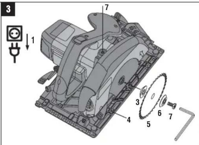
6.1.2 Fitting the saw blade 3
- Disconnect the supply cord plug from the power outlet.
- Clean the mounting flange and the clamping flang
- Fit the mounting flange.
- Open the pivoting guard.
- CAUTION Observe the direction-of-rotation a row on the saw blade.
Fit the new saw blade. - Fit the outer clamping flange.
- Secure the clamping flange by tightening the clamping screw in a clockwise direction. When doing presssthespindlelockbutton moving the blade").
- Before using the power tool, check that the saw blade is securely attached.
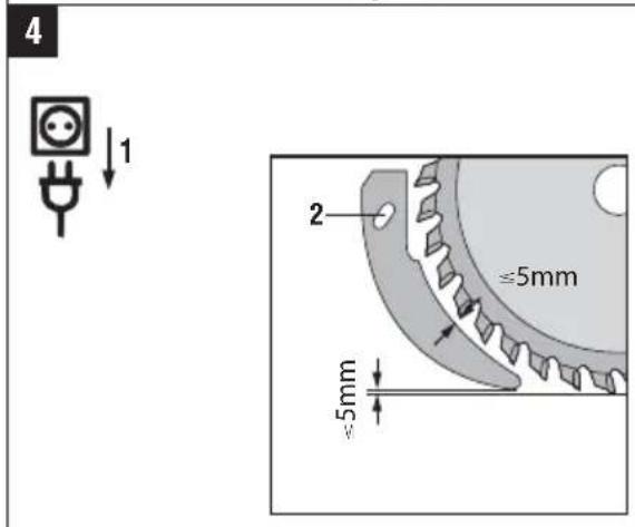
6.2 Adjusting the riving knife 4
Check to ensure that the riving knife is adjusted con The gap between the riving knife and the teeth of the blade should be no more than 5 mm and the teeth project no more than 5 mm below the lower edge of riving knife.
The riving knife prevents the blade sticking when ma longitudinal cuts. The saw may therefore be used or when the riving knife is correctly fitted and adjusted.
- Disconnect the supply cord plug from the power outlet.
-
Use a hex. socket wrench to release the hex. socket screw.
-
Adjust the riving knife as shown in the illustration.
- Use a hex. socket wrench to tighten the hex. socket screw.
6.3 Adjusting the cutting depth 5
NOTE
The cutting depth should always be set to a depth approx. The 10 mm greater than the thickness of the material to be cut.
The cutting depth can be adjusted stepplessly between 0 and 55/70 mm.
m disense with the supply cord plug from the power opened outlet.
rfect Place the power tool on a supporting surface.
- Release the cutting depth adjustment clamping lever The set cutting depth is indicated by the arrow on the scale on the gear housing.
- Lift the power tool in a scissor movement and set the desired cutting depth by closing the clamping lever.
6.4 Adjusting the cutting angle 6
The power tool can be set to any angle between 0 and 45^ for bevel cuts. Angles of up to 50^ can be set after lifting the angle extender.
- Disconnect the supply cord plug from the power outlet.
- Release the cutting angle adjustment clamping lever.
- Pivot the power tool into the desired position or, respectively, lift the angle extender to allow angles up to 50^ to be set.
e.4. Tighten the cutting angle adjustment clamping lever.
6.5 Sawing along a line
There is a cutting line indicator for straight cuts or bevel cuts (0° and 45°) at the front section of the base plate of the power tool. This permits precise cuts to be made at the selected cutting angle. The edge of the line indicator corresponds to the inside of the saw blade. The viewing window provides a better view of the cutting line and thus ensures a better cut. Additional cutting line indicators are located at the front opening for the saw blade and at the end of the base plate.
- Secure the workpiece so that it cannot move.
- Position the workpiece so that the saw blade is free to move under the workpiece.
reallyCheck to ensure that the switch on the power tool is in the off-position.
shouplug the supply cord into the power outlet.
If the Place the power tool with the base plate on the workpiece in such a way that the blade still has no king contact with the workpiece.
ly6. Press the on/off switch while the switch-on interlock is depressed.
- Guide the power tool along the cutting line on the workpiece at a suitable speed.
6.6 Sawing with the parallel guide (rip fence)
Use of the twin-arm parallel guide allows precise cuts be made along the edge of the workpiece or, respectively, strips of even width to be cut.
The parallel guide can be fitted on either side of the plate.
6.7 Fitting / adjusting the parallel guide 7
- Disconnect the supply cord plug from the power outlet.
- Slacken the clamping screw on the base plate.
- Slide both arms of the parallel guide under the clamping screw.
- Set the desired cutting width.
- Tighten the clamping screws.
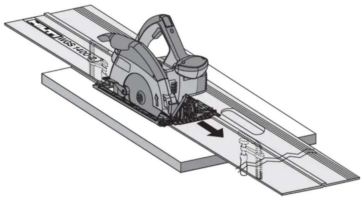
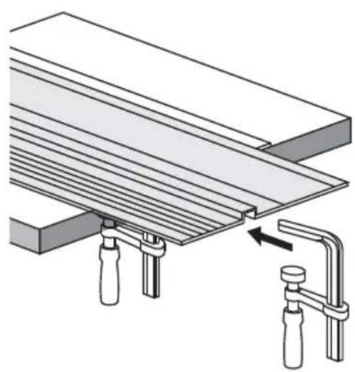
6.8 Using the saw on the guide rail 8
NOTE
Using the saw on the guide rail can reduce the risk kickback.
6.8.1 Longitudinal cuts at 0 °
Place the saw on the guide rail so that the rib fits groove in the base plate.
6.8.2 Longitudinal cuts at up to 50°
Guide the saw so that the outer edge of the base runs along the rib on the guide rail. The saw blade otherwise come into contact with the guide rail.
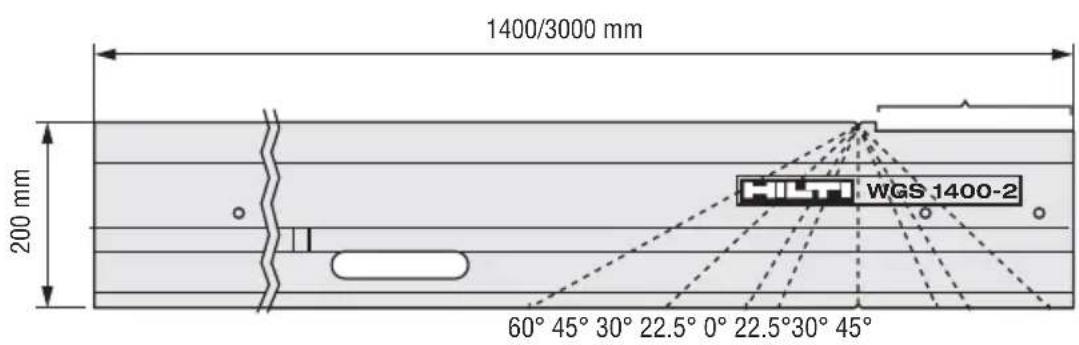
6.8.3 Cuts at an angle across the surface workpiece
NOTE
The cutting angle indicated is the angle of deviation a straight, right-angled cut.
-
Position the guide rail with the zero mark at the of the workpiece and then pivot the rail until the desired angle shown on the angle scale is oppo the zero mark.
-
Use the two screw clamps to secure the guide ra
6.9 Trimming to size
-
Secure the guide rail from below with two screw clamps. NOTE The saw must be placed on the guide behind the workpiece.
-
CAUTION Take care to ensure that the sa is not in contact with the workpiece. Position the saw on the guide rail a short distance from the starting point of the cut.
-
Switch the power tool on.
-
Push the saw steadily across the workpiece. to The pendulum guard opens as it contacts the actuating edge at the side of the guide rail and subsequently closes at the end of the rail as the cut is completed. base
6.10 Cleaning the chip ejector channel
CAUTION
Ensure that the power tool is disconnected electric supply.
en
- Press the plastic tab at the rear underside of the guard and remove the guard.
- Clean the chip ejector channel in the guard.
- Refit and secure the guard, making sure that the plastic tab engages.
- Check for misalignment or binding of moving parts, breakage of parts and any other condition that may affect the power tool's operation.
of
6.11 Using the saw with a dust and chip system 9
remov
NOTE
into the circular saw is equipped with a hose connector suitable for use with conventional vacuum cleaner hoses with a diameter of 27 mm.
plate CAUTION
wiDusts are hazardous to the health and can cause respiratory or skin diseases and allergic reactions.
of WARNING
Certain dusts are considered to be carcinogenic (cause cancer). These include mineral dust as well as oak and/or beech wood dust, particularly in conjunction with additional substances used for the treatment of wood (chromate, wood preservatives).
edge
CAUTION
Wherever possible, use a suitable mobile vacuum dust removal system such as the WVC 40-M (wood or VCU 40-M (wood and mineral materials) for the application concerned. Use a respiratory protector of the P2 filter class with half-mask facepiece if no removal system is available or its use is impossible. In addition, to keep the concentration of dust low always ensure good ventilation.
CAUTION
awCoblaclercial and industrial users must consult the responsible trade association to clarify the situat regarding special requirements applicable to working on other materials.
6.12 Using the saw without a dust and chip removal system 10
NOTE
A rotatable chip ejector is available as an accessory.
Turn the nozzle to the desired direction of ejection so that the chips and dust are deflected away from you.
7 Care and maintenance
CAUTION
Ensure that the power tool is disconnected electric supply.
7.1 Care of saw blades
Clean off dirt and dust deposits adhering to the black and protect them from corrosion by wiping from time time with an oil-soaked rag.
7.2 Care of the power tool
CAUTION
Keep the power tool, especially its grip surf clean and free from oil and grease. Do not ing agents which contain silicone.
The outer casing of the power tool is made from im resistant plastic. Sections of the grip are made from synthetic rubber material.
Never operate the power tool when the ventilation slot are blocked. Clean the ventilation slots carefully using a dry brush. Do not permit foreign objects to enter interior of the power tool. Clean the outside of the p tool at regular intervals with a slightly damp cloth. Do not use a spray, steam pressure cleaning equipment. running water for cleaning. This may negatively affect the electrical safety of the power tool.
7.3 Maintenance
WARNING
Repairs to the electrical section of the power tool be carried out only by trained electrical specialists.
CAUTION
If the power tool's supply cord is damaged it must be replaced with a specially-prepared supply cord available from Hilti Customer Service.
use .clean-
Check all external parts of the power tool for damage at regular intervals and check that all controls operate faultlessly. Do not operate the power tool if parts are act-damaged or when the controls do not function faultlessly. Have the power tool repaired by Hilti Service.
7.4 Checking the power tool after care and the maintenance
power carrying out care and maintenance work on the power tool, check that all protective and safety devices are fitted and that they function faultlessly.
8 Troubleshooting
| Fault Possible cause Remedy | ||
| The power tool doesn’t achieve full power. | The extension cord is too long or its gauge is inadequate. | Use an extension cord of an approved length and / or of adequate gauge. |
| The voltage provided by the electric supply is too low. | Connect the power tool to a different power source. | |
| The power tool doesn’t start. | Interruption in the electric supply. | Plug in another electric appliance and check whether it works. |
| The supply cord or plug is defective. | Have it checked by a trained electrical specialist and replaced if necessary. | |
| The on / off switch is defective. | Have it checked by a trained electrical specialist and replaced if necessary. | |
| The carbon brushes are worn. | Have it checked by a trained electrical specialist and replaced if necessary. | |
| The on / off switch can’t be pressed, i.e. the switch is locked. | Not a fault (safety function). | Press the switch-on interlock. |
| No / reduced suction power. | Chip ejector channel blocked. | Clean out the chip ejector channel. |
9 Disposal

Most of the materials from which Hilti power tools or appliances are manufactured can be recycled. The materials must be correctly separated before they can be recycled. In many countries, Hilti has already made arrangements for taking back your old power tools or appliances for recycling. Please ask your Hilti customer service department or Hilti representative for further information.
en

For EC countries only
Disposal of electric tools together with household waste is not permissible.
In observance of the European Directive on waste electrical and electronic equipment and its implementation in accordance with national law, electrical appliances that have reached the end of their life must be collected separately and returned to an environmentally compatible recycling facility.
10 Manufacturer's warranty - tools
Hilti warrants that the tool supplied is free of defect material and workmanship. This warrant as the tool is operated and handled correctly, cleaned and serviced properly and in accordance with the Hill Operating Instructions, and the technical system is maintained. This means that only original Hilti consumable components and spare parts may be used in the tool
This warranty provides the free-of-charge repair or replacement of defective parts only over the entire lifes of the tool. Parts requiring repair or replacement as a result of normal wear and tear are not covered by the warranty.
Additional claims are excluded, unless stringent national rules prohibit such exclusion. In particular, H is not obligated for direct, indirect, incidental or consequential damages, losses or expenses in connection with, or by reason of, the use of, or inability to use the tool for any purpose. Implied warranties of merchantability or fitness for a particular purpose as specifically excluded.
For repair or replacement, send the tool or related parts immediately upon discovery of the defect to the address of the local Hilti marketing organization provided.
This constitutes Hilti's entire obligation with regard to warranty and supersedes all prior or contemporaneous comments and oral or written agreements concerning warranties.
11 EC declaration of conformity (original)
Designation: Circular saw
Type: WSC 70 / WSC 55
Year of design: 2008
We declare, on our sole responsibility, that this product complies with the following directives and standards: 2004/108/EC, 2006/42/EC, 2011/65/EU, EN 60745-1, EN 60745-2-5, EN ISO 12100.
Hilti Corporation, Feldkircherstrasse 100, FL-9494 Schaan

Dan Demyi]
Paolo Luccini Jan Doongaji
Head of BA Quality and Process Management
Business Area Electric Tools & Ac-
cessories
01/2012 01/2012
Technical documentation filed at:
Head of BA Quality and Process Mana-
gement
Business Area Electric Tools & Acces-
sories
01/2012 01/2012
Executive Vice President
Business Unit Power
Tools & Accessories
Sierra circular manual WSC 70 / WSC 55
Head of BA Quality and Process Mana-
gement
Business Area Electric Tools & Acces-
sories
01/2012 01/2012
Executive Vice President
Business Unit Power
Tools & Accessories
Head of BA Quality and Process Management
Business Area Electric Tools & Accessories
01/2012 01/2012
Executive Vice President
Business Unit Power
Tools & Accessories
Serra circular manual WSC 70 / WSC 55
Head of BA Quality and Process Mana-
gement
Business Area Electric Tools & Acces-
sories
01/2012
Executive Vice President
Business Unit Power
Tools & Accessories
01/2012
Type: WSC 70 / WSC 55
Bouwjaar: 2008
Head of BA Quality and Process Management
Business Area Electric Tools & Accessories
01/2012 01/2012
Executive Vice President
Business Unit Power
Tools & Accessories

Paolo Luccini Jan Doongaji
Head of BA Quality and Process Management
Business Area Electric Tools & Accessories
01/2012 01/2012
Executive Vice President
Business Unit Power Tools & Accessories
Head of BA Quality and Process Mana-
gement
Business Area Electric Tools & Acces-
sories
01/2012 01/2012
Executive Vice President
Business Unit Power
Tools & Accessories
Teknisk dokumentation vid:
Head of BA Quality and Process Mana-
gement
Business Area Electric Tools & Acces-
sories
01/2012 01/2012
Executive Vice President
Business Unit Power
Tools & Accessories
Paolo Luccini Jan Doongaji
Head of BA Quality and Process
Management
Business Area Electric Tools &
Accessories
01/2012 01/2012
Executive Vice President
Business Unit Power
Tools & Accessories
Head of BA Quality and Process Management
Business Area Electric Tools &
Accessories
01/2012 01/2012
Executive Vice President
Business Unit Power
Tools & Accessories
Head of BA Quality and Process Management
Business Area Electric Tools & Accessories
01/2012 01/2012
Executive Vice President
Business Unit Power
Tools & Accessories
Head of BA Quality and Process Management
Business Area Electric Tools & Accessories
01/2012
Executive Vice President
Business Unit Power
Tools & Accessories
01/2012
Tehnilised dokumendid saadaval:
Executive Vice President
Paolo Luccini
Head of BA Quality and Process
Management
Business Area Electric Tools &
Accessories
Business Unit Power
Tools & Accessories
01/2012
01/2012
Hilti Corporation
LI-9494 Schaan
Tel.: +423 /234 21 11
Fax:+423/2342965
www.hilti.com


- WSC70/WSC55Hand-Kreissäge
- WSC70/WSC55circularsaw
- General information
- DANGER
- WARNING
- CAUTION
- NOTE
- Obligation signs
- Symbols
- Location of identification data on the power tool
- Type:
- Description
- Use of the product as directed
- Switches
- Grips
- Protective devices
- Lubrication
- Items supplied as standard
- Using extension cords
- Using extension cords outdoors
- Using a generator or transformer
- Accessories
- Technical data
- Safety instructions
- General Power Tool Safety Warnings
- Work area safety
- Electrical safety
- Personal safety
- Power tool use and care
- we###1.5 Service
- bf chil-
- ork to
- Lower guard function
- Additional safety instructions
- ng 5.6.1 Personal safety
- Power tool use and care
- Protective devices
- 6Operation
- Changing the saw blade
- Removing the saw blade 2
- Fitting the saw blade 3
- Adjusting the riving knife 4
- Adjusting the cutting depth 5
- Adjusting the cutting angle 6
- Sawing along a line
- Sawing with the parallel guide (rip fence)
- Fitting / adjusting the parallel guide 7
- Using the saw on the guide rail 8
- Longitudinal cuts at 0 °
- Longitudinal cuts at up to 50°
- Cuts at an angle across the surface workpiece
- Trimming to size
- Cleaning the chip ejector channel
- plate CAUTION
- of WARNING
- Care and maintenance
- Care of saw blades
- Care of the power tool
- Maintenance
- use .clean-
- Checking the power tool after care and the maintenance
- Troubleshooting
- Disposal
- Manufacturer's warranty - tools
- EC declaration of conformity (original)
- Sierra circular manual WSC 70 / WSC 55
- Serra circular manual WSC 70 / WSC 55
Brand : HILTI
Model : WSC 55
Category : Saw