WAG354G - Router LINKSYS - Free user manual and instructions
Find the device manual for free WAG354G LINKSYS in PDF.

User questions about WAG354G LINKSYS
0 question about this device. Answer the ones you know or ask your own.
Ask a new question about this device
Download the instructions for your Router in PDF format for free! Find your manual WAG354G - LINKSYS and take your electronic device back in hand. On this page are published all the documents necessary for the use of your device. WAG354G by LINKSYS.
USER MANUAL WAG354G LINKSYS
A Division of Cisco Systems, Inc.

natural_image
White wireless router device with dotted pattern and blue logo, no visible text or symbols on body2,4 GHz 802.11g
Wireless-G
User Guide
WIRELESS
Model No. WAG354G (EU)

Wireless-G ADSL Home Gateway
Copyright and Trademarks
Specifications are subject to change without notice. Linksys is a registered trademark or trademark of Cisco Systems, Inc. and/or its affiliates in the U.S. and certain other countries. Copyright © 2005 Cisco Systems, Inc. All rights reserved. Other brands and product names are trademarks or registered trademarks of their respective holders.
How to Use this Guide
Your Guide to the Wireless-G ADSL Home Gateway has been designed to make understanding networking with the Gateway easier than ever. Look for the following items when reading this User Guide:

This checkmark means there is a Note of interest and is something you should pay special attention to while using the Gateway.

This exclamation point means there is a Caution or Warning and is something that could damage your property or the Gateway.

This question mark provides you with a reminder about something you might need to do while using the Gateway.
In addition to these symbols, there are definitions for technical terms that are presented like this:
word: definition.
Also, each figure (diagram, screenshot, or other image) is provided with a figure number and description, like this:
Figure 0-1: Sample Figure Description
Figure numbers and descriptions can also be found in the "List of Figures" section in the "Table of Contents".
WAG354G-EU-UG-50429C JL
Wireless-G ADSL Home Gateway

Chapter 1: Introduction 1
Welcome 1
What's in this User Guide? 2
Chapter 2: Planning Your Network 4
The Gateway's Functions 4
IP Addresses 4
Chapter 3: Getting to Know the Wireless-G ADSL Home Gateway 6
Ports and Reset Button on Side Panel 6
LEDs on Side Panel 7
The Top Panel 8
The Bottom Panel 9
Chapter 4: Connecting the Wireless-G ADSL Home Gateway 10
Overview 10
Wired Connection to a Computer 11
Wireless Connection to a Computer 12
Chapter 5: Configuring the Wireless-G ADSL Home Gateway 13
Overview 13
How to Access the Web-based Utility 15
The Setup Tab 15
The Wireless Tab 23
The Security Tab 28
The Access Restrictions Tab 30
The Applications and Gaming Tab 32
The Administration Tab 37
The Status Tab 43
Appendix A: Troubleshooting 47
Common Problems and Solutions 47
Frequently Asked Questions 55
Appendix B: Wireless Security 62
Security Precautions 62
Security Threats Facing Wireless Networks 62
Wireless-G ADSL Home Gateway
Appendix C: Finding the MAC Address and IP Address for Your
Ethernet Adapter 65
Windows 98 or Me Instructions 65
Windows 2000 or XP Instructions 66
Appendix D: Upgrading Firmware 67
Appendix E: Glossary 68
Appendix F: Regulatory Information 75
Appendix G: Warranty Information 80
Appendix H: Specifications 81
Appendix I: Contact Information 83
Wireless-G ADSL Home Gateway

Figure 2-1: Network 4
Figure 3-1: Ports and Reset Button on Side Panel 6
Figure 3-2: LEDs on Side Panel 7
Figure 3-3: Top Panel 8
Figure 3-4: Top Panel with Optional Antenna 8
Figure 3-5: Bottom Panel with Stand in Closed Position 9
Figure 3-6: Gateway Using Stand 9
Figure 4-1: Connect the ADSL Line 11
Figure 4-2: Connect a PC 11
Figure 4-3: Connect the Power 11
Figure 4-4: Connect the ADSL Line 12
Figure 4-5: Connect the Power 12
Figure 5-1: Login Screen 15
Figure 5-2: Basic Setup 15
Figure 5-3: RFC 1483 Bridged - Dynamic IP 16
Figure 5-4: RFC 1483 Bridged - Static IP 16
Figure 5-5: RFC 1483 Routed 17
Figure 5-6: RFC 2516 PPPoE 17
Figure 5-7: RFC 2364 PPPoA 18
Figure 5-8: Bridged Mode Only 18
Figure 5-9: Optional Settings 19
Figure 5-10: DynDNS.org 20
Figure 5-11: TZO.com 20
Figure 5-12: Advanced Routing 21
Figure 5-13: Routing Table 22
Figure 5-14: Basic Wireless Settings 23
Figure 5-15: WPA Pre-Shared Key 24
Figure 5-16: WEP 25
Figure 5-17: Wireless Network Access 26
Figure 5-18: MAC Address Filter List 26
Figure 5-19: Wireless Client MAC List 26
Figure 5-20: Advanced Wireless Settings 27
Wireless-G ADSL Home Gateway
Figure 5-21: Security 28
Figure 5-22: Firewall Log 29
Figure 5-23: Internet Access 30
Figure 5-24: Internet Policy Summary 30
Figure 5-25: List of PCs 31
Figure 5-26: Add/Edit Service 31
Figure 5-27: Single Port Forwarding 32
Figure 5-28: Port Range Forwarding 33
Figure 5-29: Port Triggering 34
Figure 5-30: DMZ 35
Figure 5-31: QoS 36
Figure 5-32: Management 37
Figure 5-33: Allowed IP - IP Range 37
Figure 5-34: Reporting 39
Figure 5-35: System Log 39
Figure 5-36: Ping Test 40
Figure 5-37: Backup&Restore 40
Figure 5-38: Factory Defaults 41
Figure 5-39: Firmware Upgrade 41
Figure 5-40: Reboot 42
Figure 5-41: Gateway 43
Figure 5-42: Local Network 44
Figure 5-43: DHCP Active IP Table 44
Figure 5-44: ARP/RARP Table 44
Figure 5-45: Wireless 45
Figure 5-46: Networked Computers 45
Figure 5-47: DSL Connection 46
Figure C-1: IP Configuration Screen 65
Figure C-2: MAC Address/Adapter Address 65
Figure C-3: MAC Address/Physical Address 66
Figure D-1: Firmware Upgrade 67
Wireless-G ADSL Home Gateway

Welcome
Thank you for choosing the Wireless-G ADSL Home Gateway. This Gateway will provide your computers with a high-speed Internet connection as well as resources, including files and printers. Since the Gateway is wireless, Internet access can be shared over the wired network as well as the wireless broadcast at up to 11Mbps for Wireless-B or up to 54Mbps for Wireless-G.
How does the Gateway do all of this? By connecting the Internet, as well as your computers and peripherals, to the Gateway, then the Gateway can direct and control communications for your network.
To protect your data and privacy, the Gateway features an advanced firewall to keep out Internet intruders. Wireless transmissions can be protected by powerful data encryption. In addition, you can safeguard your family with parental control features such as Internet access restrictions and keyword blocking. You can configure the Gateway's settings through the easy-to-use, browser-based utility.
But what does all of this mean?
Networks are useful tools for sharing Internet access and computer resources. You can access one printer from different computers and access data located on another computer's hard drive. Networks are even used for playing multiplayer video games. So, networks not only are useful in homes and offices, but also can be fun.
PCs on a wired network create a LAN, or Local Area Network. They are connected with Ethernet cables, which is why the network is called "wired". PCs equipped with wireless cards or adapters can communicate without cumbersome cables. By sharing the same wireless settings, within their transmission radius, they form a wireless network. This is sometimes called a WLAN, or Wireless Local Area Network. Since the Gateway has wireless capabilities, it can bridge your wired and wireless networks, letting them communicate with each other.
With your networks all connected, wired, wireless, and the Internet, you can now share files and Internet access—and even play games. All the while, the Wireless-G ADSL Home Gateway protects your networks from unauthorized and unwelcome users.
Linksys recommends using the Setup CD-ROM for first-time installation of the Gateway. If you do not wish to run the Setup Wizard on the Setup CD-ROM, then use the instructions in this Guide to help you connect the Gateway, set it up, and configure it to bridge your different networks. These instructions should be all you need to get the most out of the Wireless-G ADSL Home Gateway.
wpa (wi-fi protected access): a wireless security protocol using TKIP (Temporal Key Integrity Protocol) encryption, which can be used in conjunction with a RADIUS server.
spi (stateful packet inspection) firewall: a technology that inspects incoming packets of information before allowing them to enter the network.
firewall: Security measures that protect the resources of a local network from intruders.
nat (network address translation): NAT technology translates IP addresses of a local area network to a different IP address for the Internet.
network: a series of computers or devices connected for the purpose of data sharing, storage, and/or transmission between users
Ian (local area network): The computers and networking products that make up the network in your home or office.
Wireless-G ADSL Home Gateway
What's in this User Guide?
This user guide covers the steps for setting up and using the Wireless-G ADSL Home Gateway.
• Chapter 1: Introduction This chapter describes applications of the Wireless-G ADSL Home Gateway and this User Guide.
• Chapter 2: Planning Your Network This chapter describes the basics of networking.
• Chapter 3: Getting to Know the Wireless-G ADSL Home Gateway This chapter describes the physical features of the Gateway.
- Chapter 4: Connecting the Wireless-G ADSL Home Gateway This chapter instructs you on how to connect the Gateway to your network.
- Chapter 5: Configuring the Wireless-G ADSL Home Gateway This chapter explains how to use the Web-based Utility to configure the settings on the Gateway.
- Appendix A: Troubleshooting This appendix describes some problems and solutions, as well as frequently asked questions, regarding installation and use of the Wireless-G ADSL Home Gateway.
- Appendix B: Wireless Security This appendix explains the risks of wireless networking and some solutions to reduce the risks.
- Appendix C: Finding the MAC Address and IP Address for your Ethernet Adapter. This appendix describes how to find the MAC address for your computer's Ethernet adapter so you can use the MAC filtering and/or MAC address cloning feature of the Gateway.
- Appendix D: Upgrading Firmware This appendix instructs you on how to upgrade the firmware on the Gateway if you should need to do so.
- Appendix E: Glossary This appendix gives a brief glossary of terms frequently used in networking.
- Appendix F: Specifications This appendix provides the technical specifications for the Gateway.
- Appendix G: Warranty Information This appendix supplies the warranty information for the Gateway.
Chapter 1: Introduction What's in this User Guide?
Wireless-G ADSL Home Gateway
• Appendix H: Regulatory Information
This appendix supplies the regulatory information regarding the Gateway.
- Appendix I: Contact Information
This appendix provides contact information for a variety of Linksys resources, including Technical Support.
Chapter 1: Introduction
What's in this User Guide?
Wireless-G ADSL Home Gateway
◆◆◆□▼◆◆☆◆◆◆☆◆◆□▼◆◆□▼◆
The Gateway's Functions
A Gateway is a network device that connects two networks together.
In this instance, the Gateway connects your Local Area Network (LAN), or the group of computers in your home or office, to the Internet. The Gateway processes and regulates the data that travels between these two networks.
The Gateway's NAT feature protects your network of computers so users on the public, Internet side cannot "see" your computers. This is how your network remains private. The Gateway protects your network by inspecting every packet coming in through the Internet port before delivery to the appropriate computer on your network. The Gateway inspects Internet port services like the web server, ftp server, or other Internet applications, and, if allowed, it will forward the packet to the appropriate computer on the LAN side.
Remember that the Gateway's ports connect to two sides. The LAN ports connect to the LAN, and the ADSL port connects to the Internet. The LAN ports transmit data at 10/100Mbps.
IP Addresses
What's an IP Address?
IP stands for Internet Protocol. Every device on an IP-based network, including computers, print servers, and Gateways, requires an IP address to identify its "location," or address, on the network. This applies to both the Internet and LAN connections. There are two ways of assigning an IP address to your network devices. You can assign static IP addresses or use the Gateway to assign IP addresses dynamically.
Static IP Addresses
A static IP address is a fixed IP address that you assign manually to a computer or other device on the network. Since a static IP address remains valid until you disable it, static IP addressing ensures that the device assigned it will always have that same IP address until you change it. Static IP addresses must be unique and are commonly used with network devices such as server computers or print servers.
Chapter 2: Planning Your Network The Gateway's Functions

text_image
2.4GHz 202.113 2.4GHz 202.113 InternetFigure 2-1: Network
ip (internet protocol): a protocol used to send data over a network

NOTE: Since the Gateway is a device that connects two networks, it needs two IP addresses—one for the LAN, and one for the Internet. In this User Guide, you'll see references to the "Internet IP address" and the "LAN IP address."
Since the Gateway uses NAT technology, the only IP address that can be seen from the Internet for your network is the Gateway's Internet IP address. However, even this Internet IP address can be blocked, so that the Gateway and network seem invisible to the Internet—see the Block WAN Requests description under Security in "Chapter 5: Configuring the Wireless-G ADSL Home Gateway."
Wireless-G ADSL Home Gateway
Since you use the Gateway to share your DSL Internet connection, contact your ISP to find out if they have assigned a static IP address to your account. If so, you will need that static IP address when configuring the Gateway. You can get that information from your ISP.
Dynamic IP Addresses
A dynamic IP address is automatically assigned to a device on the network, such as computers and print servers. These IP addresses are called "dynamic" because they are only temporarily assigned to the computer or device. After a certain time period, they expire and may change. If a computer logs onto the network (or the Internet) and its dynamic IP address has expired, the DHCP server will automatically assign it a new dynamic IP address.
DHCP (Dynamic Host Configuration Protocol) Servers
Computers and other network devices using dynamic IP addressing are assigned a new IP address by a DHCP server. The computer or network device obtaining an IP address is called the DHCP client. DHCP frees you from having to assign IP addresses manually every time a new user is added to your network.
A DHCP server can either be a designated computer on the network or another network device, such as the Gateway. By default, the Gateway's DHCP Server function is enabled.
If you already have a DHCP server running on your network, you must disable one of the two DHCP servers. If you run more than one DHCP server on your network, you will experience network errors, such as conflicting IP addresses. To disable DHCP on the Gateway, see the DHCP section in “Chapter 5: Configuring the Wireless-G ADSL Home Gateway.”
Wireless-G ADSL Home Gateway

text_image
Collection of symbolic and alphanumeric characters, including symbols like stars, squares, and circles with standard Latin letters.Ports and Reset Button on Side Panel
The Gateway's ports and Reset button are located on a side panel.

text_image
Line 1 2 Ethernet 3 4 Sens 12/05/08 PowerFigure 3-1: Ports and Reset Button on Side Panel
Line The Line port connects to the ADSL line.
Ethernet (1-4) The Ethernet ports connect to your computers and other network devices.
Reset Button There are two ways to reset the Gateway's factory defaults. Either press the Reset Button, for approximately ten seconds, or restore the defaults from the Factory Defaults screen of the Administration tab in the Gateway's Web-based Utility.
Power The Power port is where you will connect the power adapter.

IMPORTANT: Resetting the Gateway to factory defaults will erase all of your settings (including Internet connection, wireless, and other settings) and replace them with the factory defaults. Do not reset the Gateway if you want to retain these settings.
Wireless-G ADSL Home Gateway
LEDs on Side Panel
The Gateway's LEDs, which indicate network activity, are located on the other side panel.
text_image
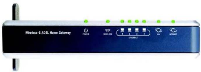
Wireless-6 ADSL Home Gateway POWER WIRELESS 1 2 3 4 ETHIOMET DSL INTERNETFigure 3-2: LEDs on Side Panel
POWER Green. The POWER LED lights up when the Gateway is powered on.
WIRELESS Green. The WIRELESS LED lights up whenever there is a successful wireless connection. If the LED is flashing, the Gateway is actively sending or receiving data to or from one of the devices on the network.
ETHERNET (1-4) Green. The ETHERNET LED serves two purposes. If the LED is continuously lit, the Gateway is successfully connected to a device through the LAN port. If the LED is flashing, it is an indication of any network activity.
DSL Green. The DSL LED lights up whenever there is a successful DSL connection. The LED blinks while the Gateway is establishing the ADSL connection.
INTERNET Green. The INTERNET LED lights up green when an Internet connection to the Internet Service Provider (ISP) is established. The INTERNET LED lights up red when the connection to the ISP fails.
Wireless-G ADSL Home Gateway
The Top Panel
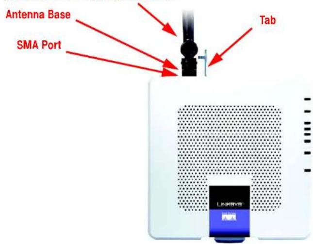
The Gateway comes with a built-in antenna; however, you can attach an optional antenna. (Note: This antenna is currently not available in Europe.) The Linksys 5dBi High Gain Antenna for SMA Connectors (model number: HGA5S) is available for increased range. The Gateway's SMA port for the optional antenna is located on the top panel. To access the SMA port, push the tab. To attach the antenna, insert the base of the antenna into the SMA port and tighten it clockwise by hand.

natural_image
Blue mechanical lever handle with circular and rectangular slots (no text or symbols)Figure 3-3: Top Panel
Optional Linksys 5dBi Antenna (model number: HGA5S) Note: This antenna is currently not available in Europe. For other options please visit www.linksys.com/international.
text_image
Antenna Base SMA Port Tab LINKSYSFigure 3-4: Top Panel with Optional Antenna
Chapter 3: Getting to Know the Wireless-G ADSL Home Gateway The Top Panel
Wireless-G ADSL Home Gateway
The Bottom Panel
The Gateway has a built-in stand available. If you place the Gateway flat on a surface, then you can leave the stand in the closed position. However, if you want the Gateway to be upright, swivel the stand clockwise 90° and position the Gateway accordingly.

Figure 3-5: Bottom Panel with Stand in Closed Position

natural_image
Front view of a white wireless router with a blue 'LINKSYS' logo and control panel (no readable text beyond branding)Figure 3-6: Gateway Using Stand
Chapter 3: Getting to Know the Wireless-G ADSL Home Gateway The Bottom Panel
Wireless-G ADSL Home Gateway

text_image
Collection of symbolic icons including asterisks, squares, and stars in various colors and shapesOverview
The installation technician from your ISP should have left the setup information for the modem with you after installing your broadband connection. If not, you can call your ISP to request that data.
After you have the setup information you need for your specific type of Internet connection, you can begin installation and setup of the Gateway.
If you want to use a computer with an Ethernet adapter to configure the Gateway, continue to "Wired Connection to a Computer." If you want to use a computer with a wireless adapter to configure the Gateway, continue to "Wireless Connection to a Computer."
Wireless-G ADSL Home Gateway
Wired Connection to a Computer
- Make sure that all of your network's hardware is powered off, including the Gateway and all computers.
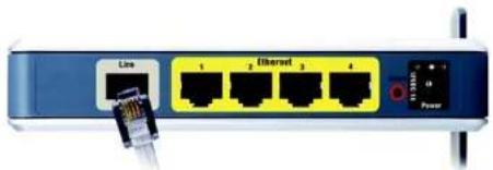
- Connect a phone cable from the Line port on the Gateway's side panel to the wall jack of the ADSL line. A small device called a microfilter (not included) may be necessary between each phone and wall jack to prevent interference. Contact your ISP if you have any questions.

NOTE: A small device called a microfilter (not included) may be necessary between each phone and wall jack to prevent interference. Contact your ISP if you have any questions.

IMPORTANT: For countries that have phone jacks with RJ-11 connectors, make sure to only place the microfilters between the phone and the wall jack and not between the Gateway and the wall jack or your ADSL will not connect.
For countries that do not have phone jacks with RJ-11 connectors (e.g. France, Sweden, Switzerland, United Kingdom, etc.), except for ISDN users, the microfilter has to be used between the Gateway and the wall jack, because the microfilter will have the RJ-11 connector.
Annex B users (E1 and DE versions of the Gateway) must use the included special cable to connect the Gateway to the wall jack (RJ-45 to RJ-12). If you require splitters or special jacks, please contact your service provider.
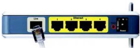
- Connect one end of an Ethernet network cable to one of the Ethernet ports (labeled 1-4) on the back of the Gateway, and the other end to an Ethernet port on a computer.
Repeat this step to connect more computers, a switch, or other network devices to the Gateway.
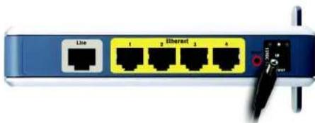
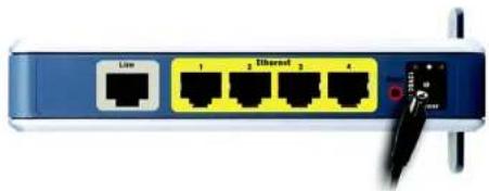
- Connect the power adapter to the Gateway's Power port, and then plug the power adapter into a power outlet.

NOTE: You should always plug the Gateway's power adapter into a power strip with surge protection.
The Power LED on the front panel will light up green as soon as the power adapter is connected properly. The Power LED will flash for a few seconds, and then it will be solidly lit when the self-test is complete. If the LED flashes for one minute or longer, see "Appendix A: Troubleshooting."
- Power on one of your computers that is connected to the Gateway.
Go to "Chapter 5: Configuring the Wireless-G ADSL Home Gateway."
Chapter 4: Connecting the Wireless-G ADSL Home Gateway Wired Connection to a Computer
natural_image
Front view of a network switch with Ethernet ports and a USB cable (no text or symbols visible)Figure 4-1: Connect the ADSL Line

natural_image
Close-up of a network switch with Ethernet port and power cable, no visible text or symbols on the device itself.Figure 4-2: Connect a PC
natural_image
Front view of a network switch with Ethernet ports and a USB port (no text or symbols visible)Figure 4-3: Connect the Power
Wireless-G ADSL Home Gateway
Wireless Connection to a Computer
If you want to use a wireless connection to access the Gateway, follow these instructions:
- Make sure that all of your network's hardware is powered off, including the Gateway and all computers.
- Connect a phone cable from the Line port on the Gateway's back panel to the wall jack of the ADSL line. A small device called a microfilter (not included) may be necessary between each phone and wall jack to prevent interference. Contact your ISP if you have any questions.

NOTE: A small device called a microfilter (not included) may be necessary between each phone and wall jack to prevent interference. Contact your ISP if you have any questions.

IMPORTANT: For countries that have phone jacks with RJ-11 connectors, make sure you only place the microfilters between the phone and the wall jack and not between the Gateway and the wall jack or your ADSL will not connect.
For countries that do not have phone jacks with RJ-11 connectors (e.g. France, Sweden, Switzerland, United Kingdom, etc.), except for ISDN users, the microfilter has to be used between the Gateway and the wall jack, because the microfilter will have the RJ-11 connector.
Annex B users (E1 and DE versions of the Gateway) must use the included special cable to connect the Gateway to the wall jack (RJ-45 to RJ-12). If you require splitters or special jacks, please contact your service provider.
- Connect the power adapter to the Power port, and then plug the power adapter into a power outlet.
The Power LED on the front panel will light up green as soon as the power adapter is connected properly. The Power LED will flash for a few seconds, and then it will be solidly lit when the self-test is complete. If the LED flashes for one minute or longer, see "Appendix A: Troubleshooting." - Power on one of the computers on your wireless network(s).
- For initial access to the Gateway through a wireless connection, make sure the computer's wireless adapter has its SSID set to linksys (the Gateway's default setting), and its wireless security is disabled. After you have accessed the Gateway, you can change the Gateway and this computer's adapter settings to match your usual network settings.
Go to "Chapter 5: Configuring the Wireless-G ADSL Home Gateway."
natural_image
Close-up of a network switch with four Ethernet ports and a USB cable connector (no visible text or symbols)Figure 4-4: Connect the ADSL Line
natural_image
Blue network switch with four Ethernet ports and a black cable connector (no visible text or symbols)Figure 4-5: Connect the Power

NOTE: You should always change the SSID from its default, linksys, and enable wireless security.
Wireless-G ADSL Home Gateway
◆◆◆□▼◆□×+◆□■◆◆□■★◆◆◆◆▲▲☆◆◆◆★◆○※ ◆◆◆D
Overview
Follow the steps in this chapter and use the Gateway's web-based utility to configure the Gateway. This chapter will describe each web page in the Utility and each page's key functions. The utility can be accessed via your web browser through use of a computer connected to the Gateway. For a basic network setup, most users only have to use the following screens of the Utility:
- Basic Setup. On the Basic Setup screen, enter the settings provided by your ISP.
- Management. Click the Administration tab and then the Management tab. The Gateway's default username and password is admin. To secure the Gateway, change the Password from its default.
There are seven main tabs: Setup, Wireless, Security, Access Restrictions, Applications & Gaming, Administration, and Status. Additional tabs will be available after you click one of the main tabs.
Setup
- Basic Setup. Enter the Internet connection and network settings on this screen.
- DDNS. To enable the Gateway's Dynamic Domain Name System (DDNS) feature, complete the fields on this screen.
- Advanced Routing. On this screen, you can alter NAT and routing configurations.
Wireless
- Basic Wireless Settings. You can choose your wireless network settings on this screen.
- Wireless Security. Configure your wireless security settings on this screen.
- Wireless Access. This screen lets you control access to your wireless network.
- Advanced Wireless Settings. On this screen you can access the advanced wireless network settings.

HAVE YOU: Enabled TCP/IP on your computers? Computers communicate over the network with this protocol. Refer to Windows Help for more information on TCP/IP.

NOTE: For added security, you should change the password through the Administration tab.
Wireless-G ADSL Home Gateway
Security
On this screen you can disable or enable the firewall, set up filters, block WAN requests, and enable or disable Virtual Private Networks (VPN) PassThrough.
Access Restrictions
- Internet Access. This screen allows you to control the Internet usage and traffic on your local network.
Applications & Gaming
- Single Port Forwarding. Use this screen to set up common services or applications that require forwarding on a single port.
- Port Range Forwarding. To set up public services or other specialized Internet applications that require forwarding on a range of ports, use this screen.
- Port Triggering. To set up triggered ranges and forwarded ranges for Internet applications, click this tab.
- DMZ. To allow one local computer to be exposed to the Internet for use of special-purpose services, use this screen.
- QoS. Use Quality of Service (QoS) to assign different priority levels to different types of data transmissions.
Administration
- Management. On this screen, alter Gateway access, Simple Network Management Protocol (SNMP), Universal Plug and Play (UPnP), IGMP-Proxy (IGMP stands for Internet Group Multicast Protocol), and wireless management settings.
- Reporting. If you want to view or save activity logs, click this tab.
• Diagnostics. Use this screen to run a Ping test. - Backup&Restore. On this screen, you can back up or restore the Gateway's configuration.
- Factory Defaults. If you want to restore the Gateway's factory default settings, use this screen.
- Firmware Upgrade. Click this tab if you want to upgrade the Gateway's firmware.
- Reboot. If you need to do a hard or soft reboot of the Gateway, use this screen.
Chapter 5: Configuring the Wireless-G ADSL Home Gateway Overview
vpn (virtual private network): a security measure to protect data as it leaves one network and goes to another over the Internet.
Wireless-G ADSL Home Gateway
Status
• Gateway. This screen provides status information about the Gateway.
- Local Network. This provides status information about the local network.
- Wireless. This screen provides status information about the wireless network.
- DSL Connection. This screen provides status information about the DSL connection.
How to Access the Web-based Utility
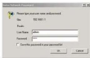
To access the web-based utility, launch Internet Explorer or Netscape Navigator, and enter the Gateway's default IP address, 192.168.1.1, in the Address field. Then press Enter.
A login screen will appear (Windows XP users will see a similar screen). Enter admin (the default user name) in the User Name field, and enter admin (the default password) in the Password field. Then click the OK button.
The Setup Tab
The Basic Setup Tab
The first screen that appears is the Basic Setup tab. This tab allows you to change the Gateway's general settings. Change these settings as described here and click the Save Settings button to save your changes, or click the Cancel Changes button to cancel your changes.
Internet Setup
- Internet Connection Type. The Gateway supports five Encapsulation methods: RFC 1483 Bridged, RFC 1483 Routed, RFC 2516 PPPoE, RFC 2364 PPPoA, and Bridged Mode Only. Select the appropriate type of encapsulation from the drop-down menu. Each Basic Setup screen and available features will differ depending on what type of encapsulation you select.
- VC Settings. You will configure your Virtual Circuit (VC) settings in this section.
• Multiplexing: Select LLC or VC, depending on your ISP. - QoS Type: Select from the drop-down menu: CBR (Continuous Bit Rate) to specify fixed bandwidth for voice or data traffic; UBR (Unspecific Bit Rate) for application that are none-time sensitive, such as e-mail; or VBR (Variable Bite Rate) for Bursty traffic and bandwidth-sharing with other applications.
Chapter 5: Configuring the Wireless-G ADSL Home Gateway How to Access the Web-based Utility
text_image
User Network Password Please type your user name and password. Site: 192.1681.1 Login Name: admin Password: "" Save this password in your password list OK CancelFigure 5-1: Login Screen

text_image
LINKSYS Setup Windows / Windows Name: NewCity Setup: Design Options Security Access/Reception Applications & Settings Administrative Name Server Settings Internal Connection Type XC Settings Displacement: AFC HBS Submitted Multi-Link: 1.1.1.1.1.1.1.1.1.1.1.1.1.1.1.1.1.1.1.1.1.1.1.1.1.1.1.1.1.1.1.1.1.1.1.1.1.1.1.1.1.1.1.1.1.1.1.1.1.1.1 Go Type: USA Go Type: non Automated: F default P default Value Output: 50 V/Charge (200) 33 V/Charge (20000) P Settings * Update on IP Address Automatically * Update Following IP Address Internal IP Address: Subtotal Method: Delete Method: Primary MNC: Secondary MNC: PPM/Source: Disable Optional Settings grapled by name (B/C) Print Time: Print Time: Auto MCC: 0000000000000000000000000000000000000000000000000000000000000000000000000000000000000000 System Settings Radio: P Network Address Server Settings (RRC) Local TCP Server: 577 849 577 577 Subtotal Method: 577 765 377 6 6 Local TCP Server: 577 849 577 6 6 Local TCP Server: 577 849 577 6 6 Starting IP Address: 988,888,888,888,888,888,888,888,888,888,888,888,888,888,888,888,888,888,888,888,888,888,888,888,888,888, 577 Local TCP Server: 577 849 577 6 6 Local TCP Server: 577 849 577 6 6 Local TCP Server: 577 849 577 6 6 Local TCP Server: 577 849 577 6 6 Local TCP Server: 577 849 577 6 6 Local TCP Server: 577 849 5T Local TCP Server: 577 849 5T Local TCP Server: 577 849 5T Local TCP Server: 577 849 5T Local TCP Server: 577 849 5T Local TCP Server: 577 849 5T Time Setting Time Zone: DCAT/RD3/DCAT/Pack Time (USAS Console) Test Interval: DSD/DCAT/DCAT/DCAT/DCAT/DCAT/DCAT/DCAT/DCAT/DCAT/DCAT/DCAT/DCAT/DCAT/DCAT/DCAT/DCAT/DCAT/DCAT/DCAT/DCAT/DCAT/DCAT/DCAT/DCAT/DCAT/DCAT/DCAT/DCAT/DCAT/DCAT/DCAT/DCAT/DCAT/DCAT/ Start Settings Reserved ChangesFigure 5-2: Basic Setup
Wireless-G ADSL Home Gateway
- Pcr Rate: For the Peak Cell Rate, divide the DSL line rate by 424 to get the maximum rate the sender can send cells. Enter the rate in the field (if required by your service provider).
- Scr Rate: The Sustain Cell Rate sets the average cell rate that can be transmitted. The SCR value is normally less than the PCR value. Enter the rate in the field (if required by your service provider).
- Autodetect: Select Enable to have the settings automatically entered, or select Disable to enter the values manually.
- Virtual Circuit: These fields consist of two items: VPI (Virtual Path Identifier) and VCI (Virtual Channel Identifier). Your ISP will provide the correct settings for these fields.
- IP Settings. Follow the instructions in the section for your type of encapsulation.
RFC 1483 Bridged
Dynamic IP
IP Settings. Select Obtain an IP Address Automatically if your ISP says you are connecting through a dynamic IP address.
Static IP
If you are required to use a permanent (static) IP address to connect to the Internet, then select Use the following IP Address.
- Internet IP Address. This is the Gateway's IP address, when seen from the WAN, or the Internet. Your ISP will provide you with the IP Address you need to specify here.
- Subnet Mask. This is the Gateway's Subnet Mask. Your ISP will provide you with the Subnet Mask.
- Gateway. Your ISP will provide you with the default Gateway Address, which is the ISP server's IP address.
- Primary DNS (Required) and Secondary DNS (Optional). Your ISP will provide you with at least one DNS (Domain Name System) Server IP Address.

text_image
Internet Setup Internet Connection Type VC Settings Encapsulation: RFC 1-433 Bridged Multiplications: LLC VC QoS Type: UBR For Rate: 0%ps Scr Rate: 0%ps Autodefect: Enable Enable Virtual Circuit: 0 VIT (Range 0-255) VCI: VCI (Range 32-65508) IP Settings: Obtain an IP Address Automatically Use the following IP Address: Internet P Address: □ □ □ □ Submit Mask: □ □ □ □ Gateway: □ □ □ □ Primary DNS: □ □ □ □ Secondary DNS: □ □ □ □Figure 5-3: RFC 1483 Bridged - Dynamic IP

text_image
Internet Setup Internet Connection Type WC Settings Encapsulation: RFC 1483 Bridged * Multiplexing: LLC VC Qas Type: UBR * For Rate: cps Scr Rate: cps Autodirect: Enable Enable Virtual Circuit: 0 VP (Range 0-265) 15 VQ (Range 32-8553) IP Settings Obtain an IP Address Automatically Use the following IP Address: Internet IP Address: 0 1 2 0 Submit Mask: 0 1 2 0 Delivery: 0 1 2 0 Primary DND: 0 1 2 0 Secondary DND: 0 1 2 0Figure 5-4: RFC 1483 Bridged - Static IP
Wireless-G ADSL Home Gateway
RFC 1483 Routed
If you are required to use RFC 1483 Routed, then select RFC 1483 Routed.
- Internet IP Address. This is the Gateway's IP address, when seen from the WAN, or the Internet. Your ISP will provide you with the IP Address you need to specify here.
- Subnet Mask. This is the Gateway's Subnet Mask. Your ISP will provide you with the Subnet Mask.
- Gateway. Your ISP will provide you with the default Gateway Address, which is the ISP server's IP address.
- Primary DNS (Required) and Secondary DNS (Optional). Your ISP will provide you with at least one DNS (Domain Name System) Server IP Address.
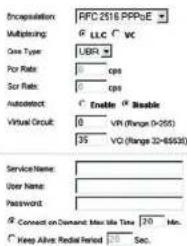
RFC 2516 PPPoE
Some DSL-based ISPs use PPPoE (Point-to-Point Protocol over Ethernet) to establish Internet connections. If you are connected to the Internet through a DSL line, check with your ISP to see if they use PPPoE. If they do, you will have to enable PPPoE.
• Service Name. Enter the name of your PPPoE service in this field.
- User Name and Password. Enter the User Name and Password provided by your ISP.
- Connect on Demand: Max Idle Time. You can configure the Gateway to disconnect the Internet connection after it has been inactive for a specified period of time (Max Idle Time). If your Internet connection has been terminated due to inactivity, Connect on Demand enables the Gateway to automatically re-establish your connection as soon as you attempt to access the Internet again. To use this option, click the Connect on Demand radio button. In the Max Idle Time field, enter the number of minutes you want to have elapsed before your Internet connection terminates.
- Keep Alive: Redial Period. If you select this option, the Gateway will periodically check your Internet connection. If you are disconnected, then the Gateway will automatically re-establish your connection. To use this option, click the Keep Alive radio button. In the Redial Period field, specify how often you want the Gateway to check the Internet connection. The default Redial Period is 20 seconds.


text_image
Encapsulation: RFC1483 Routed Multiplexing: LLC VC QoQ Type: UBR Por Rate: cps Cor Rate: cps Autodetect: Enable Disable Virtual Circuit: VR (Range 0-255) 0 0 0 0 0 0 0 0 0 0 0 0 0 0 0 0 0 0 0 0 0 0 0 0 0 0 0 0 0 0 0 0 0 0 0 0 0 0 0 0 0 0 0 0 0 0 0 0 0 0 0Figure 5-5: RFC 1483 Routed

text_image
Incorporation: RFC 2518 PPPoE Multiplexing: LLC VC Case Type: UBR Por Rate: cps Scr Rate: cps Autodetect: Enable & Enable Virtual Circuit: 0 VPI (Range 0-255) 35 VCI (Range 20-85930) Service Name: User Name: Password: Connect on Demand: Max life Time 20 Min. Keep Alive: Redial Period Sec.Figure 5-6: RFC 2516 PPPoE
Wireless-G ADSL Home Gateway
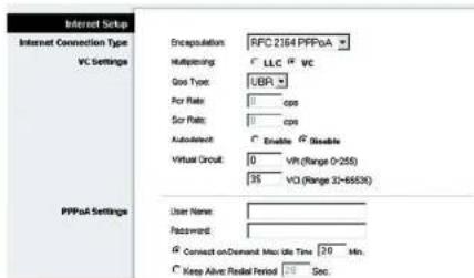
RFC 2364 PPPoA
Some DSL-based ISPs use PPPoA (Point-to-Point Protocol over ATM) to establish Internet connections. If you are connected to the Internet through a DSL line, check with your ISP to see if they use PPPoA. If they do, you will have to enable PPPoA.
- User Name and Password. Enter the User Name and Password provided by your ISP.
- Connect on Demand: Max Idle Time. You can configure the Gateway to disconnect the Internet connection after it has been inactive for a specified period of time (Max Idle Time). If your Internet connection has been terminated due to inactivity, Connect on Demand enables the Gateway to automatically re-establish your connection as soon as you attempt to access the Internet again. To use this option, click the Connect on Demand radio button. In the Max Idle Time field, enter the number of minutes you want to have elapsed before your Internet connection terminates.
- Keep Alive: Redial Period. If you select this option, the Gateway will periodically check your Internet connection. If you are disconnected, then the Gateway will automatically re-establish your connection. To use this option, click the Keep Alive radio button. In the Redial Period field, specify how often you want the Gateway to check the Internet connection. The default Redial Period is 20 seconds.
Bridged Mode Only
If you are using your Gateway as a bridge, which makes the Gateway act like a stand-alone modem, select Bridged Mode Only. All NAT and routing settings are disabled in this mode.
Optional Settings (required by some ISPs)
- Host Name and Domain Name. These fields allow you to supply a host and domain name for the Gateway. Some ISPs require these names as identification. You may have to check with your ISP to see if your broadband Internet service has been configured with a host and domain name. In most cases, you can leave these fields blank.
- MTU and Size. The MTU (Maximum Transmission Unit) setting specifies the largest packet size permitted for network transmission. Select Manual and enter the value desired in the Size field. It is recommended that you leave this value in the 1200 to 1500 range. By default, MTU is configured automatically.
Network Setup
- Router IP. The values for the Gateway's Local IP Address and Subnet Mask are shown here. In most cases, keeping the default values will work.
Chapter 5: Configuring the Wireless-G ADSL Home Gateway The Setup Tab
text_image
Internet Setup Internet Connection Type VC Settings Encapsulation: AFC 2164 PPPoA Multiplexing: LLC FC VC Gas Type: UBR For Rate: 0 cps For Rate: 0 cps Autodetect: Enable R Enable Virtual Circuit: 0 VPI (Range 0-255) 3S VCI (Range 32-6553X) PPPoA Settings User Name: Password: Connect on Demand Mode Time 24 Min. Keep Alive Real Period Sec.Figure 5-7: RFC 2364 PPPoA

text_image
Internet Setup Internet Connection Type VC Settings Incorporation: Bridge Mode Only Multiporations: LLC VC Box Type: UER Por Rate: 0 cps Sor Rate: 0 cps AutoSelect: Enable Enable Virtual Circuit: 0 VRI (Range 0-255) 35 VCI (Range 30-65530) Optional Settings (required by some ISPs) Next Name: Domain Name: MTR: Auto Size: 1492Figure 5-8: Bridged Mode Only
Wireless-G ADSL Home Gateway
- Local IP Address. The default value is 192.168.1.1.
- Subnet Mask. The default value is 255.255.255.0.
- Network Address Server Settings (DHCP). Configure the Gateway's Dynamic Host Configuration Protocol (DHCP) settings in this section.
- Local DHCP Server. A Dynamic Host Configuration Protocol (DHCP) server automatically assigns an IP address to each computer on your network for you. Unless you already have one, it is highly recommended that you leave the Gateway enabled as a DHCP server. You can also use the Gateway in DHCP Relay mode.
- DHCP Relay Server. If you enable the DHCP Relay mode for the Local DHCP Server setting, enter the IP address for the DHCP server in the fields provided.
- Starting IP Address. Enter a value for the DHCP server to start with when issuing IP addresses. This value must be 192.168.1.2 or greater, because the default IP address for the Gateway is 192.168.1.1.
• Maximum Number of DHCP Users. Enter the maximum number of users/clients that can obtain an IP address. The number will vary depending on the starting IP address entered.
- Client Lease Time. The Client Lease Time is the amount of time a computer will be allowed connection to the Gateway with its current dynamic IP address. Enter the amount of time, in minutes, that the computer will be "leased" this dynamic IP address.
- Static DNS 1-3. The Domain Name System (DNS) is how the Internet translates domain or website names into Internet addresses or URLs. Your ISP will provide you with at least one DNS Server IP Address. You can enter up to three DNS Server IP Addresses here. The Gateway will use these for quicker access to functioning DNS servers.
- WINS. The Windows Internet Naming Service (WINS) converts NetBIOS names to IP addresses. If you use a WINS server, enter that server's IP address here. Otherwise, leave this field blank.
- Time Setting. Select the appropriate time zone for the Gateway's location. If desired, check the Automatically adjust clock for daylight saving changes checkbox.
When finished making your changes on this tab, click the Save Settings button to save these changes, or click the Cancel Changes button to undo your changes.

text_image
Optional Settings (required by some RFs) Host Name: Domain Name: INTU: Auto Size: 1192 Network Setup Router IP Local IP Address: 172, 160, 1, 1 Submit Mask: 255, 255, 255, 0 Network Address Server Settings (DKCP) Local DHCP Server: Enable Enable DHCP Relay DHCP Relay Server: 0 0 0 0 Starting IP Address: 152,188,5,0.4 Maximum Number of DHCP Users: 191 Client Lease Time: 0 minutes (0 means one day) Static DNS 1: 0 0 0 Static DNS 2: 0 0 0 Static DNS 3: 0 0 0 WING: 0 0 0 Time Setting Time Zone: (GMT-08.00 Pacific Time (USA & Canada)) Time Interval: 36.00 seconds Automatically adjust clock for default saving changesFigure 5-9: Optional Settings
Wireless-G ADSL Home Gateway
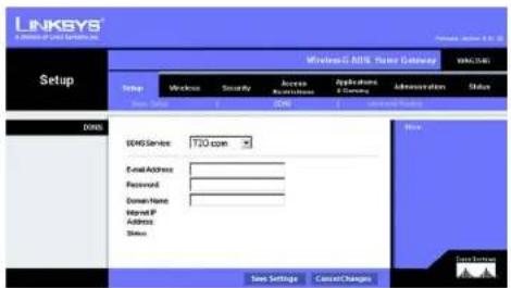
The DDNS Tab
The Gateway offers a Dynamic Domain Name System (DDNS) feature. DDNS lets you assign a fixed host and domain name to a dynamic Internet IP address. It is useful when you are hosting your own website, FTP server, or other server behind the Gateway.
Before you can use this feature, you need to sign up for DDNS service at DynDNS.org or TZO.com.
DDNS
DDNS Service. If your DDNS service is provided by DynDNS.org, then select DynDNS.org from the drop-down menu. If your DDNS service is provided by TZO.com, then select TZO.com from the drop-down menu. To disable DDNS Service, select Disabled.
DynDNS.org
- User Name, Password, and Host Name. Enter the User Name, Password, and Host Name of the account you set up with DynDNS.org.
- Internet IP Address. The Gateway's current Internet IP Address is displayed here. Because it is dynamic, it will change.
- Status. The status of the DDNS service connection is displayed here.
TZ0.com
- E-mail Address, Password, and Domain Name. Enter the E-mail Address, Password, and Domain Name of the account you set up with TZO.
- Internet IP Address. The Gateway's current Internet IP Address is displayed here. Because it is dynamic, this will change.
- Status. The status of the DDNS service connection is displayed here.
When finished making your changes on this tab, click the Save Settings button to save these changes, or click the Cancel Changes button to undo your changes.

text_image
LINKSYS A software of DOS Systems, Inc. Setup Wireless C: BIOS System Gateway VOC: [H:C] Setup Wireless Security Access Administration Applications & Services Administration Status User Setup DOS Advanced Platform BOS BOS Service: CyE-DRG.org User Name: Password: Mail Name: Internet P: Address: Status: Save Settings Cancel Changes Store Bus Data SourceFigure 5-10: DynDNS.org
text_image
LINKSYS® www.rinksys.com Setup Windows: C: BNS, Server Gateway WIN: C:\WIN Status Name: Wireless Security Access Applications Administration Status Show Setup C: BNS Show Settings Cancel Changes DNS EWS Service 120 com Email Address Password Domain Name Mail IP Address Show Show Settings Cancel Changes Time Settings Cancel ChangesFigure 5-11: TZO.com
Wireless-G ADSL Home Gateway
The Advanced Routing Tab
The Advanced Routing screen allows you to configure the NAT, dynamic routing, and static routing settings.
Advanced Routing
- Operating Mode. In this section, you will configure the Gateway's general routing settings.
- NAT. NAT is a security feature that is enabled by default. It enables the Gateway to translate IP addresses of your local area network to a different IP address for the Internet. To disable NAT, click the Disabled radio button.
- RIP. If you have multiple routers, you may want to use the Routing Information Protocol (RIP) so the routers can exchange routing information with each other. To use RIP, select the Enabled radio button. Otherwise, keep the default, Disabled.
- Send Default Route. To use RIP version 1 for routing, select the Enabled radio button. Otherwise, keep the default, Disabled.
- Interface. This setting is available when you have configured a static route and you need to choose an interface for that route. Select the interface that the Gateway will be using: LAN/Wireless or Internet.
- Dynamic Routing. With Dynamic Routing you can enable the Gateway to automatically adjust to physical changes in the network's layout. Using RIP, the Gateway determines the network packets' route based on the fewest number of hops between the source and the destination. The RIP protocol regularly broadcasts routing information to other Gateways on the network.
- Transmit RIP Version. To transmit RIP messages, select the protocol you want: RIP1, RIP1-Compatible, or RIP2. If you don't want to transmit RIP messages, select None.
- Receive RIP Version. To receive RIP messages, select the protocol you want: RIP1 or RIP2. If you don't want to receive RIP messages, select None.
- Multicast or Broadcast. RIP can be sent using either methods. If you want to use multicasting, select Multicast. If you want to use Broadcast, select Broadcast.
- Static Routing. If the Gateway is connected to more than one network, it may be necessary to set up a static route between them. A static route is a pre-determined pathway that network information must travel to reach a specific host or network. To create a static route, change the following settings:

text_image
LINKSYS A Division of Data Systems, Inc. Setup Wireless & ARSL Network Scaling Status OK Cancel Set Up Send Settings Security Access Application & Connection Administration Status Automatic Routing Adverse and Routing Operating Mode NA: Enabled Disabled RIP Enabled Disabled Send Default Route Enable Disabled Interface Transient RIP Version: ASP1 Receiving RIP Version: ASP1 MultiBand or Broadcast: MultiBand Static Routing Select set number: 1 Delete This Entry: Destination IP Address: 0 0 0 0 Submit Work: 0 0 0 0 Outperform: 0 0 0 0 Map Check: 1 Show Routing Tabo Save Settings Cancel Changes Next Save SettingsFigure 5-12: Advanced Routing
Wireless-G ADSL Home Gateway
- Select set number. Select the number of the static route from the drop-down menu. The Gateway supports up to 20 static route entries. If you need to delete a route, then select the entry and click the Delete This Entry button.
- Destination IP Address. The Destination IP Address is the address of the remote network or host to which you want to assign a static route. Enter the IP address of the host for which you wish to create a static route. If you are building a route to an entire network, be sure that the network portion of the IP address is set to 0.
- Subnet Mask. Enter the Subnet Mask (also known as the Network Mask), which determines which portion of an IP address is the network portion, and which portion is the host portion.
- Gateway. Enter the IP address of the gateway device that allows for contact between the Gateway and the remote network or host.
- Hop Count. Hop Count is the number of hops to each node until the destination is reached (16 hops maximum). Enter the Hop Count in the field provided.
- Show Routing Table. Click the Show Routing Table button to open a screen displaying how data is routed through your local network. For each route, the Destination LAN IP address, Subnet Mask, Gateway, and Interface are displayed. Click the Refresh button to update the information. Click the Close button to return to the previous screen.
When finished making your changes on this tab, click the Save Settings button to save these changes, or click the Cancel Changes button to undo your changes.

Figure 5-13: Routing Table
Wireless-G ADSL Home Gateway
The Wireless Tab
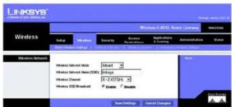
The Basic Wireless Settings Tab
This screen allows you to choose your wireless network mode and wireless security.
Wireless Network
- Wireless Network Mode. If you have 802.11g and 802.11b devices in your network, then keep the default setting, Mixed. If you have only 802.11g devices, select 802.11g. If you have only 802.11b devices, select 802.11b. If you want to disable wireless networking, select Disabled.
- Wireless Network Name (SSID). Enter the name for your wireless network into the field. The SSID is the network name shared among all devices in a wireless network. It must be identical for all devices in the wireless network. It is case-sensitive and must not exceed 32 alphanumeric characters, which may be any keyboard character. Linksys recommends that you change the default SSID (linksys) to a unique name of your choice.
- Wireless Channel. Select the appropriate channel from the list provided to correspond with your network settings. All devices in your wireless network must use the same channel in order to function correctly. Wireless computers or clients will automatically detect the wireless channel of the Gateway.
- Wireless SSID Broadcast. When wireless computers or clients survey the local area for wireless networks to associate with, they will detect the SSID broadcast by the Gateway. To broadcast the Gateway's SSID, keep the default setting, Enable. If you do not want to broadcast the Gateway's SSID, then select Disable.
When finished making your changes on this tab, click the Save Settings button to save these changes, or click the Cancel Changes button to undo your changes.
text_image
LINKSYS A Network of Data Systems, Inc. Windows 0.40% Name Currency Wireless Wireless Network Mode: Mixed Wireless Network Name (SDD): Linksys Wireless Channel: -2.07946 Wireless SSD Broadcast: Enable Disable Save Settings Cancel Changes Back Data SummaryFigure 5-14: Basic Wireless Settings
Wireless-G ADSL Home Gateway
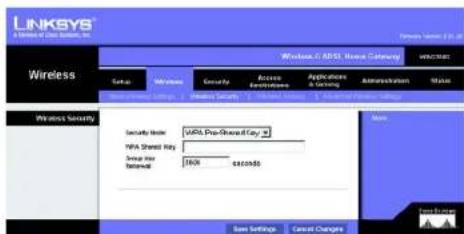
The Wireless Security Tab
The Wireless Security settings configure the security of your wireless network. There are two wireless security options supported by the Gateway: WPA Pre-Shared Key and WEP. (WPA stands for Wi-Fi Protected Access, which is a security standard stronger than WEP encryption. WEP stands for Wired Equivalent Privacy.) These are briefly discussed here. For detailed instructions on configuring wireless security for the Gateway, turn to "Appendix B: Wireless Security." If you want to disable wireless security, select Disable from the drop-down menu for Security Mode.
WPA Pre-Shared Key. Enter a WPA Shared Key of 8-32 characters. Then enter a Group Key Renewal period, which instructs the Gateway how often it should change the encryption keys.
text_image
LINKSYS A Security Of Data Systems, Inc. Windows C:\ASP\Home Category WINSCH Wireless Seto Windows Security Access Application Administration Name Wireless Security Security Note: WINS (Pre-Shared Key) WPS Shared Key Snap Over Retinal: Jack seconds Main Save Settings Cancel Changes Next UpdateFigure 5-15: WPA Pre-Shared Key
Wireless-G ADSL Home Gateway
WEP. WEP is a basic encryption method, which is not as secure as WPA. To use WEP, select a Default Key (this indicates which Key to use) and a level of WEP encryption, 64 bits 10 hex digits or 128 bits 26 hex digits. Then either generate a WEP key using a Passphrase or enter the WEP key manually.
- WEP Encryption. An acronym for Wired Equivalent Privacy, WEP is an encryption method used to protect your wireless data communications. WEP uses 64-bit or 128-bit keys to provide access control to your network and encryption security for every data transmission. To decode data transmissions, all devices in a network must use an identical WEP key. Higher encryption levels offer higher levels of security, but due to the complexity of the encryption, they may decrease network performance. To enable WEP, select 64 bits 10 hex digits or 128 bits 26 hex digits.
- Default Transmit Key Select which WEP key (1-4) will be used when the Gateway sends data. Make sure that the receiving device (wireless computer or client) is using the same key.
- Passphrase. Instead of manually entering WEP keys, you can enter a passphrase. This passphrase is used to generate one or more WEP keys. It is case-sensitive and should not be longer than 32 alphanumeric characters. (This Passphrase function is compatible with Linksys wireless products only and cannot be used with Windows XP Zero Configuration. If you want to communicate with non-Linksys wireless products or Windows XP Zero Configuration, make a note of the WEP key generated in the Key 1 field, and enter it manually in the wireless computer or client.) After you enter the Passphrase, click the Generate button to create WEP keys.
- WEP Keys 1-4. WEP keys enable you to create an encryption scheme for wireless network transmissions. If you are not using a Passphrase, then manually enter a set of values. (Do not leave a key field blank, and do not enter all zeroes; they are not valid key values.) If you are using 64-bit WEP encryption, the key must be exactly 10 hexadecimal characters in length. If you are using 128-bit WEP encryption, the key must be exactly 26 hexadecimal characters in length. Valid hexadecimal characters are "0"-"9" and "A"-"F".
When finished making your changes on this tab, click the Save Settings button to save these changes, or click the Cancel Changes button to undo your changes. For detailed instructions on configuring wireless security for the Gateway, turn to "Appendix B: Wireless Security."

text_image
LINKSYS A Version of Data Setset, Inc. Wireless G ADSL Home Setting WRC2000 Setup Wireless Security Access Refreshlist Applicable & Closing Administration Status Wireless Security Security Mode: MEP Defined Transit Key MHP Description: 14 bits 10 new digits Accessless Conservative Key 1: Key 2: Key 3: Key 4: New Settings Cancel Changes Data GroupFigure 5-16: WEP
Wireless-G ADSL Home Gateway
The Wireless Access Tab
Wireless Network Access
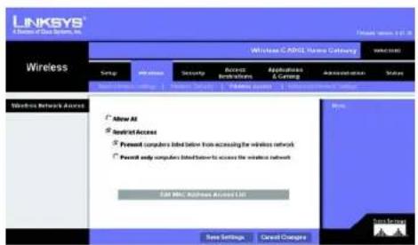
Wireless Network Access. Select Allow All you want all computers to have access to the wireless network. To restrict access to the network, select Restrict Access, and then select Prevent to block access for the designated computers or Permit only to permit access for the designated computers. Click the Edit MAC Address Access List button, and the Mac Address Filter List screen will appear.
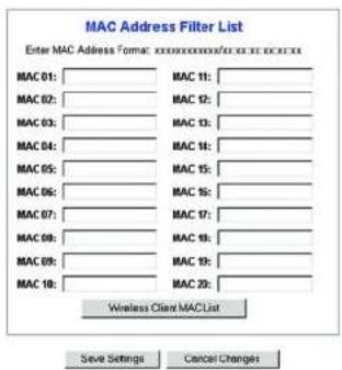
Enter the MAC addresses of the computers you want to designate. To see a list of MAC addresses for wireless computers or clients, click the Wireless Client MAC List button.
The Wireless Client MAC List screen will list computers, their IP addresses, and their MAC addresses. Click the Refresh button to get the most up-to-date information. Click the Enable MAC Filter checkbox To add a specific computer to the Mac Address Filter List, click the Enable MAC Filter checkbox and then the Update Filter List button. Click the Close button to return to the Wireless Client MAC List screen.
On the Wireless Client MAC List screen, click the Save Settings button to save this list, or click the Cancel Changes button to remove your entries.
When finished making your changes on this tab, click the Save Settings button to save these changes, or click the Cancel Changes button to undo your changes.
text_image
LINKSYS A Series of Data Systems, Inc. Wireless LinkSYS C:\ADSL Home Database Settings Setup Wireless Security Access Resources Application & Comp Administration Status Wireless Network Access Allow All Install Access Present computers listed below from accessing the wireless network Payout only computers listed below to access the wireless network Edit MBC: Microsoft Access List Save Settings Direct Change Home SecurityFigure 5-17: Wireless Network Access
text_image
MAC Address Filter List Enter MAC Address Format: xxxxxxxxxxxxxxxxx/xxxxxxxx MAC 01:______________ MAC 11:______________ MAC 02:______________ MAC 12:______________ MAC 03:______________ MAC 13:______________ MAC 04:______________ MAC 14:______________ MAC 05:______________ MAC 15:______________ MAC 06:______________ MAC 16:______________ MAC 07:______________ MAC 17:______________ MAC 08:______________ MAC 18:______________ MAC 09:______________ MAC 19:______________ MAC 10:______________ MAC 20:______________ Wireless Client MACList Save Settings Cancel ChangesFigure 5-18: MAC Address Filter List
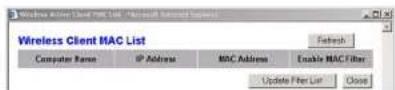
Figure 5-19: Wireless Client MAC List
Wireless-G ADSL Home Gateway
The Advanced Wireless Settings Tab
Advanced Wireless
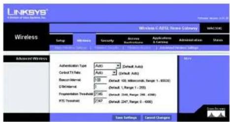
On this screen you can access the advanced wireless features, including Authentication Type, Control TX Rate, Beacon Interval, DTIM Interval, Fragmentation Threshold, and RTS Threshold.
- Authentication Type. The default is set to Auto, which allows either Open System or Shared Key authentication to be used. For Open System authentication, the sender and the recipient do not use a WEP key for authentication but can use WEP for data encryption. To only allow Open System authentication, select Open System. For Shared Key authentication, the sender and recipient use a WEP key for both authentication and data encryption. To only allow Shared Key authentication, select Shared Key. It is recommended that this option be left in the default (Auto) mode, because some clients cannot be configured for Shared Key.
- Control Tx Rates The default transmission rate is Auto. The rate should be set depending on the speed of your wireless network. Select from a range of transmission speeds, or keep the default setting, Auto, to have the Gateway automatically use the fastest possible data rate and enable the Auto-Fallback feature. Auto-Fallback will negotiate the best possible connection speed between the Gateway and a wireless client.
- Beacon Interval. The default value is 100. The Beacon Interval value indicates the frequency interval of the beacon. A beacon is a packet broadcast by the Gateway to synchronize the wireless network.
- DTIM Interval. The default value is 1. This value indicates the interval of the Delivery Traffic Indication Message (DTIM). A DTIM field is a countdown field informing clients of the next window for listening to broadcast and multicast messages. When the Gateway has buffered broadcast or multicast messages for associated clients, it sends the next DTIM with a DTIM Interval value. Its clients hear the beacons and awaken to receive the broadcast and multicast messages.
- Fragmentation Threshold. This value should remain at its default setting of 2346. It specifies the maximum size for a packet before data is fragmented into multiple packets. If you experience a high packet error rate, you may slightly increase the Fragmentation Threshold. Setting the Fragmentation Threshold too low may result in poor network performance. Only minor modifications of this value are recommended.
- RTS Threshold. This value should remain at its default setting of 2347. If you encounter inconsistent data flow, only minor modifications are recommended. If a network packet is smaller than the preset RTS threshold size, the RTS/CTS mechanism will not be enabled. The Gateway sends Request to Send (RTS) frames to a particular receiving station and negotiates the sending of a data frame. After receiving an RTS, the wireless station responds with a Clear to Send (CTS) frame to acknowledge the right to begin transmission.
When finished making your changes on this tab, click the Save Settings button to save these changes, or click the Cancel Changes button to undo your changes.
Chapter 5: Configuring the Wireless-G ADSL Home Gateway The Wireless Tab
text_image
LINKSYS A Division of Internet Services, Inc. Wireless Windows C: A/BUS Name Category MACSAC Setup Wireless Security Access Maintenance Applications A License Administration Status Setup Access Maintenance Applications A License Advanced Wireless Settings Advanced Wireless Authentication Type Auto (Default Auto) Cutoff T1 Rate Auto (Default Auto) Scan-Interval 00 Default 100, Miscellaneous, Range 1 - 40000 C/D Interval 0 Default 1, Range 1 - 2500 Registration Threshold 748 Default 368, Range 368 - 4368 RTS Threshold 247 Default 247, Range 0 - 4000 Menu Settings Cancel Changes May Save Settings Cancel ChangesFigure 5-20: Advanced Wireless Settings
Wireless-G ADSL Home Gateway
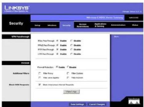
The Security Tab
This screen shows the VPN passthrough, firewall, and filter settings. Use these features to enhance the security of your network.
VPN Passthrough
Virtual Private Networking (VPN) is a security measure that basically creates a secure connection between two remote locations. Configure these settings so the Gateway will permit VPN tunnels to pass through.
- IPSec Passthrough. Internet Protocol Security (IPSec) is a suite of protocols used to implement secure exchange of packets at the IP layer. To allow IPSec Passthrough, click the Enable button. To disable IPSec Passthrough, click the Disable button.
- PPPoE Passthrough. PPPoE Passthrough allows your PC(s) to use the PPPoE client software provided by your ISP. Some ISPs may request that you use this feature on the Gateway. To allow PPPoE Passthrough, click the Enable button. To disable PPPoE Passthrough, click the Disable button.
- PPTP Passthrough. Point-to-Point Tunneling Protocol Passthrough is the method used to enable VPN sessions to a Windows NT 4.0 or 2000 server. To allow PPTP Passthrough, click the Enable button. To disable PPTP Passthrough, click the Disable button.
- L2TP Passthrough. Layering 2 Tunneling Protocol Passthrough is an extension of the Point-to-Point Tunneling Protocol (PPTP) used to enable the operation of a VPN over the Internet. To allow L2TP Passthrough, click the Enable button. To disable L2TP Passthrough, click the Disable button.
Firewall
You can enable or disable the firewall, select filters to block specific Internet data types, and block anonymous Internet requests.
To use the firewall, click Enable. If you do not want to use the firewall, click Disable.
Additional Filters
- Filter Proxy. Use of WAN proxy servers may compromise the Gateway's security. Denying Filter Proxy will disable access to any WAN proxy servers. To enable proxy filtering, click the checkbox.
- Filter Cookies. A cookie is data stored on your computer and used by Internet sites when you interact with them. To enable cookie filtering, click the checkbox.
Chapter 5: Configuring the Wireless-G ADSL Home Gateway The Security Tab
text_image
LINKSYS A Division of Data Systems, Inc. Windows 6. ADSL Finance Setting Security Setup Windows Security Access (Disclosures) Applications (A & C) Administration Status V5P PassThrough PhD PassThrough: Enable Disable PhD PassThrough: Enable Disable PhD PassThrough: Enable Disable USB PassThrough: Enable Disable Forward Protection: Enable Disable Add/Remove Filters File Proxy Filter Cookies File store directory File macro Show Any Personal Messages Show Image Save Settings Cancel Changes New Save For Save For Save Settings Cancel ChangesFigure 5-21: Security
Wireless-G ADSL Home Gateway
- Filter Java Applets. Java is a programming language for websites. If you deny Java Applets, you run the risk of not having access to Internet sites created using this programming language. To enable Java Applet filtering, click the checkbox.
- Filter ActiveX. ActiveX is a programming language for websites. If you deny ActiveX, you run the risk of not having access to Internet sites created using this programming language. To enable ActiveX filtering, click the checkbox.
Block WAN Requests
- Block Anonymous Internet Requests. This keeps your network from being "pinged" or detected and reinforces your network security by hiding your network ports, so it is more difficult for intruders to discover your network. Select Block Anonymous Internet Requests to block anonymous Internet requests or de-select it to allow anonymous Internet requests.
If you want to see activity logs for your security measures, then click the View Logs button. Click the Clear button to clear the log information. Click the pageRefresh button to refresh the information. Click the Previous Page button to go to the previous page of information. Click the Next Page button to move to the next page of information.
When finished making your changes on this tab, click the Save Settings button to save these changes, or click the Cancel Changes button to undo your changes.

text_image
System Log Firewall Log ▼ Clear pageRefresh Clear pageRefresh Previous Page NextPageFigure 5-22: Firewall Log
Wireless-G ADSL Home Gateway
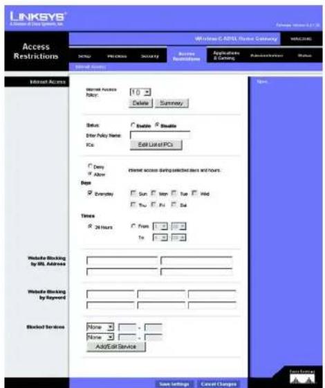
The Access Restrictions Tab
The Internet Access Tab
The Internet Access screen allows you to block or allow specific kinds of Internet usage. You can set up Internet access policies for specific computers and block websites by URL address or keyword.
Internet Access Policy. Access can be managed by a policy. Use the settings on this screen to establish an access policy (after the Save Settings button is clicked). Selecting a policy from the drop-down menu will display that policy's settings. To delete a policy, select that policy's number and click the Delete button. To view all the policies, click the Summary button. (Policies can be deleted from the Summary screen by selecting the policy or policies and clicking the Delete button. To return to the Internet Access screen, click the Close button.)
Status. Policies are disabled by default. To enable a policy, select the policy number from the drop-down menu, and click the radio button beside Enable.
To create an Internet Access policy:
- Select a number from the Internet Access Policy drop-down menu.
- To enable this policy, click the radio button beside Enable.
- Enter a Policy Name in the field provided.
text_image
LINKSYS Access Restrictions Welcome C:\APTEL\Stop Command WELCOME Status External Access Normal Access Policy: 10 Delete Summary Address Enable Enable Enter Policy Name: Klc Edit List of PCI Send Send Send Send Send Send Send Send Send Send Send Send Send Send Send Send Send Send Send Send Send Send Send Send Send Send Send Send Send Send Send Send Send Send Send Send Send Send Send Send Send Send Send Send Send Send Send Send Send Send Svcs Svcs Svcs Svcs Svcs Svcs Svcs Svcs Svcs Svcs Svcs Svcs Svcs Svcs Svcs Svcs Svcs Svcs Svcs Svcs Svcs Svcs Svcs Svcs Svcs SvCS SvCS SvCS SvCS SvCS SvCS SvCS SvCS SvCS SvCS SvCS SvCS SvCS SvCS SvCS SvCS SvCS SvCS SvCS SvCS SvCS SvCS SvCS SvCS SvCS SvCnCnCnCnCnCnCnCnCnCnCnCnCnCnCnCnCnCnCnCnCnCnCnCnCnCnCnCnCnCnCnCnCnCnCnCnCnCnCnCnCnCnCnCnCnCnCnCnCnCnCmCmCmCmCmCmCmCmCmCmCmCmCmCmCmCmCmCmCmCmCmCmCmCmCmCmCmCmCmCmCmCmCmCmCmCmCmCmCmCmCmCmCmCmCmCmCmCmCmCmCcmcMcmcMcmcMcmcMcmcMcmcMcmcMcmcMcmcMcmcMcmcMcmcMcmcMcmcMcmcMcmcMcmcMcmcMcmcMcmcMcmcMcmcMcmcMcmcMcmcMcmcMcmcMcmcMcmcMcmcMcmcMcmcMcmcMcmcMsmcMsmcMsmcMsmcMsmcMsmcMsmcMsmcMsmcMsmcMsmcMsmcMsmcMsmcMsmcMsmcMsmcMsmcMsmcMsmcMsmcMsmcMsmcMsmcMsmcMsmcMsmcMsmcMsmcMsmcMsmcMsmcMsmcMsmoMsmoOmsOmsOmsOmsOmsOmsOmsOmsOmsOmsOmsOmsOmsOmsOmsOmsOmsOmsOmsOmsOmsOmsOmsOmsOmsOmsOmsOmsOmsOmsOmsOmsOmsOmsOmsOmsOmsOmsOmsOmsOmsOmsOmsOmsOmsOmsOmsOmsOmsOmsOtsOtsOtsOtsOtsOtsOtsOtsOtsOtsOtsOtsOtsOtsOtsOtsOtsOtsOtsOtsOtsOtsOtsOtsOtsOtsOtsOtsOtsOtsOtsOtsOtsOtsOtsOtsOtsOtsOtsOtsOtsOtsOtsOtsOtsOtsOtsOtsOtsOtsOits Oits Oits Oits Oits Oits Oits Oits Oits Oits Oits Oits Oits Oits Oits Oits Oits Oits Oits Oits Oits Oits Oits Oits Oits Oits Oits Oits Oits Oits Oits Oits Oits Oits Oits Oits Oits Oits Oits Oits Oits Oits Oits Oits Oits Oits Oits Oits Oits Oits Oits Svm Cvm Cvm Cvm Cvm Cvm Cvm Cvm Cvm Cvm Cvm Cvm Cvm Cvm Cvm Cvm Cvm Cvm Cvm Cvm Cvm Cvm Cvm Cvm Cvm Cvm Cvm Cvm Cvm Cvm Cvm Cvm Cvm Cvm Cvm Cvm Cvm Cvm Cvm Cvm Cvm Cvm Cvm Cvm Cvm Cvm Cvm Cvm Cvm Cvm Cvm AFigure 5-23: Internet Access

text_image
Internet Policy Summary No. Policy Name Days Time of Day Orders 1 -- SMTWTPS -- □ 2 -- SMTWTPS -- □ 3 -- SMTWTPS -- □ 4 -- SMTWTPS -- □ 5 -- SMTWTPS -- □ 6 -- SMTWTPS -- □ 7 -- SMTWTPS -- □ 8 -- SMTWTPS -- □ 9 -- SMTWTPS -- □ 10 -- SMTWTPS -- □ CloseFigure 5-24: Internet Policy Summary
Wireless-G ADSL Home Gateway
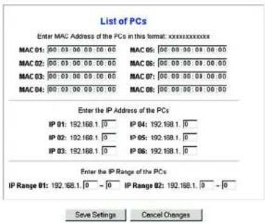
- Click the Edit List of PCs button to select which PCs will be affected by the policy. The List of PCs screen will appear. You can select a PC by MAC Address or IP Address. You can also enter a range of IP Addresses if you want this policy to affect a group of PCs. After making your changes, click the Save Settings button to apply your changes or Cancel Changes to cancel your changes.
- Click the appropriate option, Deny or Allow, depending on whether you want to block or allow Internet access for the PCs you listed on the List of PCs screen.
- Decide which days and what times you want this policy to be enforced. Select the individual days during which the policy will be in effect, or select Everyday. Then enter a range of hours and minutes during which the policy will be in effect, or select 24 Hours.
- If you want to block websites with specific URL addresses, enter each URL in a separate field next to Website Blocking by URL Address.
- If you want to block websites using specific keywords, enter each keyword in a separate field next to Website Blocking by Keyword.
- You can filter access to various services accessed over the Internet, such as FTP or telnet, by selecting services from the drop-down menus next to Blocked Services.
Then enter the range of ports you want to filter.
If the service you want to block is not listed or you want to edit a service's settings, then click the Add/Edit Service button. Then the Port Services screen will appear.
To add a service, enter the service's name in the Service Name field. Select its protocol from the Protocol drop-down menu, and enter its range in the Port Range fields. Then click the Add button.
To modify a service, select it from the list on the right. Change its name, protocol setting, or port range. Then click the Modify button.
To delete a service, select it from the list on the right. Then click the Delete button.
When you are finished making changes on the Port Services screen, click the Apply button to save changes. If you want to cancel your changes, click the Cancel button. To close the Port Services screen and return to the Access Restrictions screen, click the Close button.
- Click the Save Settings button to save the policy's settings. To undo the policy's settings, click the Cancel Changes button.
Chapter 5: Configuring the Wireless-G ADSL Home Gateway The Access Restrictions Tab
text_image
List of PCs Enter MAC Address of the PCs in this temat: xxxxxxxxxx MAC 01: 00:03:00:00:00:00 MAC 02: 00:03:00:00:00:00 MAC 03: 00:03:00:00:00:00 MAC 04: 00:03:00:00:00:00 MAC 05: 00:09:00:01:00:00 MAC 06: 00:09:00:01:00:00 MAC 07: 00:09:00:01:00:00 MAC 08: 00:09:00:01:00:00 Enter the IP Address of the PCs IP 01: 192.168.1 [ ] IP 04: 192.168.1 [ ] IP 02: 192.168.1 [ ] IP 05: 192.168.1 [ ] IP 03: 192.168.1 [ ] IP 06: 192.168.1 [ ] Enter the IP Range of the PCs IP Range 01: 192.168.1 [ ] - [ ] IP Range 02: 192.168.1 [ ] - [ ] Save Settings Cancel ChangesFigure 5-25: List of PCs

text_image
Service Name DNS Protocol UDP Port Range 53 - 83 Add Modify Delete DNS [63 ~ 51] Ping[0 ~ 0] HTTP [80 ~ 80] HTTPS [443 ~ 443] FTP[2 ~ 21] POP3 [110 ~ 110] NAP[143 ~ 143] SMTP [26 ~ 26] NTP [119 ~ 119] Telnet [23 ~ 23] SNMP [161 ~ 161] TFTP [39 ~ 89] Apply Cancel CloseFigure 5-26: Add/Edit Service
Wireless-G ADSL Home Gateway
The Applications and Gaming Tab
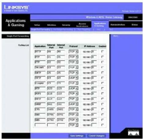
The Single Port Forwarding Tab
Single Port Forwarding
Use the Single Port Forwarding screen when you want to open a specific port so users on the Internet can see the servers behind the Gateway (such servers may include FTP or e-mail servers). When users send this type of request to your network via the Internet, the Gateway will forward those requests to the appropriate computer. Any computer whose port is being forwarded should have its DHCP client function disabled and should have a new static IP address assigned to it because its IP address may change when using the DHCP function.
- Port Map List. In this section you will customize the port service for your applications.
- Application. Enter the name of the application in the field provided.
- External Port and Internal Port. Enter the External and Internal Port numbers.
- Protocol. Select the protocol you wish to use for each application: TCP or UDP.
- IP Address. Enter the IP Address of the appropriate computer.
- Enabled. Click Enabled to enable forwarding for the chosen application.
When finished making your changes on this tab, click the Save Settings button to save these changes, or click the Cancel Changes button to undo your changes.
text_image
LINKSYS J. P###e of C#e, M####, N# Applications & Gaming Network: G-ATSL Home Gateway WALWING Setup Volumes Security Access Application Administration Status Single Port Forwarding PortMap Ltd Application External Port Internal Port Protocol IP Address Enabled BFTP 109 86 TCP ▼ 2.168-0 ▼ BFTP 21 21 TCP ▼ 2.168-0 ▼ BFTP 22 22 TCP ▼ 2.168-0 ▼ D#d.com 23 23 TCP ▼ 2.168-0 ▼ SOTP 25 25 TCP ▼ 2.168-0 ▼ BFTP 49 49 UDP ▼ 2.168-0 ▼ E Tagged 79 79 TCP ▼ 2.168-0 ▼ BFTP 123 123 UDP ▼ 2.168-0 ▼ POP3 118 118 TCP ▼ 2.168-0 ▼ POPc 113 113 TCP ▼ 2.168-0 ▼ SOTP 142 142 UDP ▼ 2.168-0 ▼ EVs 2401 2401 TCP ▼ 2.168-0 ▼ SMS 2760 2760 TCP ▼ 2.168-0 ▼ SMS 2702 2702 TCP ▼ 2.168-0 ▼ Save Settings Cancel Changes MenuFigure 5-27: Single Port Forwarding
Wireless-G ADSL Home Gateway
The Port Range Forwarding Tab
The Port Range Forwarding screen sets up public services on your network, such as web servers, ftp servers, e-mail servers, or other specialized Internet applications. (Specialized Internet applications are any applications that use Internet access to perform functions such as videoconferencing or online gaming. Some Internet applications may not require any forwarding.)
When users send this type of request to your network via the Internet, the Gateway will forward those requests to the appropriate computer. Any computer whose port is being forwarded should have its DHCP client function disabled and should have a new static IP address assigned to it because its IP address may change when using the DHCP function.
- Application. Enter the name of the application in the field provided.
- Start and End. Enter the starting and ending numbers of the port range you wish to forward.
- Protocol. Select the protocol you wish to use for each application: TCP, UDP, or Both.
- IP Address. Enter the IP Address of the appropriate computer.
- Enable. Click the Enable checkbox to enable forwarding for the chosen application.
When finished making your changes on this tab, click the Save Settings button to save these changes, or click the Cancel Changes button to undo your changes.

text_image
LINKSYS A GAMES OF LIME SYSTEMS, INC. Applications & Gaming Windows & ANSI Home Calendar WINCHES: Setup Wireless Security Access Instructions Application Security Administration Status Port Range Forwarding Port Range Application Start End Protocol P Address Enable Port Range Forwarding Port Range 20 to 9 Both 102.1681.1 20 to 9 Both 102.1681.1 20 to 9 Both 102.1681.1 20 to 9 Both 102.1681.1 20 to 9 Both 102.1681.1 20 to 9 Both 102.1681.1 20 to 30 30 to 9 Both 102.1681.1 30 to 9 Both 102.1681.1 30 to 9 Both 102.1681.1 30 to 9 30 to 9 30 to 9 30 to 9 30 to 9 30 to 9 30 to 9 Save Settings Cancel ChangesFigure 5-28: Port Range Forwarding
Wireless-G ADSL Home Gateway
The Port Triggering Tab
Port Triggering is used for special applications that can request a port to be opened on demand. For this feature, the Gateway will watch outgoing data for specific port numbers. The Gateway will remember the IP address of the computer that sends a transmission requesting data, so that when the requested data returns through the Gateway, the data is pulled back to the proper computer by way of IP address and port mapping rules.
• Application. Enter the name you wish to give each application.
- Triggered Range. Enter the starting and ending port numbers of the Triggered Range.
- Forwarded Range. Enter the starting and ending port numbers of the Forwarded Range.
- Enable. Click the Enable checkbox to enable port triggering for the chosen application.
When finished making your changes on this tab, click the Save Settings button to save these changes, or click the Cancel Changes button to undo your changes.
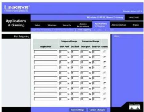
text_image
LINKSYS A Software Data System, Inc. Applications & Gaming Wntelone C: AOSL Home Database MM/XXX Setup Vehicles Security Access Applications Administrations Status Start Port End Port Start port End Port Enable Port Logging 1. 2. 3. 4. 5. 6. 7. 8. 9. 10. 11. 12. 13. 14. 15. 16. 17. 18. 19. 20. 21. 22. 23. 24. 25. 26. 27. 28. 29. 30. 31. 32. 33. 34. 35. 36. 37. 38. 39. 40. 41. 42. 43. 44. 45. 46. 47. 48. 49. 50. 51. 52. 53. 54. 55. 56. 57. 58. 59. 60. 61. 62. 63. 64. 65. 66. 67. 68. 69. 70. 71. 72. 73. 74. 75. 76. 77. 78. 79. 80. 81. 82. 83. 84. 85. 86. 87. 88. 89. 90. 91. 92. 93. 94. 95. 96. 97. 98. 99. 100. Port Logging Triggered Range Forward Red Range Application Start Port End Part Start port End Part End 0 to B B to D B to E B to F B to G B to H B to I B to J B to K B to L B to M B to N B to O B to P B to Q B to R B to S B to T B to U B to V B to W B to X B to Y B to Z B to AA B to AB B to AC B to AD B to AE B to AF B to AG B to AH B to AI B to AJ B to AK B to AL B to AM B to AN B to AO B to AP B to AQ B to AR B to AS B to AT B to AU B to AV B to AW B to AX B to AY B to AZ B to BA B to BB B to BC B to BD B to BE B to BF B to BG B to BH B to BI B to BJ B to BKJ B to BLKJ B to BLKJJ B to BLKJYJ B to BLKJYJYJ B to BLKJYJYJYJ Save Settings Cancel ChangeFigure 5-29: Port Triggering
Wireless-G ADSL Home Gateway
The DMZ Tab
The DMZ screen allows one local user to be exposed to the Internet for use of a special-purpose service such as Internet gaming and videoconferencing through DMZ Hosting. DMZ hosting forwards all the ports for one computer at the same time, which differs from Port Range Forwarding, which can only forward a maximum of 10 ranges of ports.
- DMZ Hosting. This feature allows one local user to be exposed to the Internet for use of a special-purpose service such as Internet gaming and videoconferencing. To use this feature, select Enable. To disable DMZ, select Disable.
- DMZ Host IP Address. To expose one computer, enter the computer's IP address. To get the IP address of a computer, refer to "Appendix C: Finding the MAC Address and IP Address for Your Ethernet Adapter."
When finished making your changes on this tab, click the Save Settings button to save these changes, or click the Cancel Changes button to undo your changes.
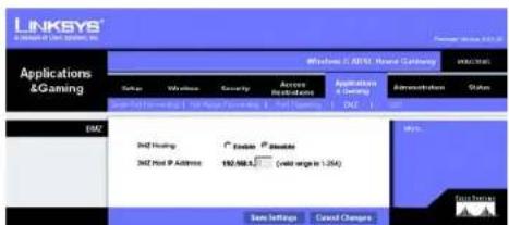
text_image
LINKSYS A Gaining (I) - 2013 Applications & Gaming Windows 5.2 (MSL) Portal Catalog Status Windows Security Access Applications Applications & Catalog Administration Status Select Print Functioning & Print Functioning & Print Options Add Add Settings Add Hosting C Adder C Adder Add Host IP Address Add No. 2 (web sign in .254) Save Settings Cancel Changes Add HistoryFigure 5-30: DMZ
Wireless-G ADSL Home Gateway
The QoS Tab
QoS
Quality of Service (QoS) ensures better service to high-priority types of network traffic, which may involve demanding, real-time applications, such as Internet phone calls or videoconferencing.
Enabled/Disabled. To use QoS, select Enable. Otherwise, keep the default, Disable.
Application-based QoS
Application-based QoS manages information as it is transmitted and received. Depending on the settings of the QoS screen, this feature will assign information a high or low priority for the five preset applications and three additional applications that you specify.
High priority/Medium priority/Low priority. For each application, select High priority (traffic on this queue shares 60% of the total bandwidth), Medium priority (traffic on this queue shares 18% of the total bandwidth), or Low priority (traffic on this queue shares 1% of the total bandwidth).
FTP (File Transfer Protocol). A protocol used to transfer files over a TCP/IP network (Internet, UNIX, etc.). For example, after developing the HTML pages for a website on a local machine, they are typically uploaded to the web server using FTP.
HTTP (HyperText Transport Protocol). The communications protocol used to connect to servers on the World Wide Web. Its primary function is to establish a connection with a web server and transmit HTML pages to the client web browser.
Telnet. A terminal emulation protocol commonly used on Internet and TCP/IP-based networks. It allows a user at a terminal or computer to log onto a remote device and run a program.
SMTP (Simple Mail Transfer Protocol). The standard e-mail protocol on the Internet. It is a TCP/IP protocol that defines the message format and the message transfer agent (MTA), which stores and forwards the mail.
POP3 (Post Office Protocol 3). A standard mail server commonly used on the Internet. It provides a message store that holds incoming e-mail until users log on and download it. POP3 is a simple system with little selectivity. All pending messages and attachments are downloaded at the same time. POP3 uses the SMTP messaging protocol.
Specific Port#. You can add three more applications by entering their respective port numbers in these fields.
When you have finished making changes to this screen, click the Save Settings button to save the changes, or click the Cancel Changes button to undo your changes.
Chapter 5: Configuring the Wireless-G ADSL Home Gateway The Applications and Gaming Tab

text_image
LINKSYS A Software & Gaming System Applications &Gaming Windows C:\MOS\Material Category Setup Network Security Access Application Administration Name Specialty: 100% Low Security High Security Low Security FTP C C C FTP C C C Subnet C C C SMTP C C C POP C C C Specific Port0 C C C Specific Port0 C C C Specific Port0 C C C Specific Port0 C C C SaaS Settings Cancel ChangesFigure 5-31: QoS
Wireless-G ADSL Home Gateway
The Administration Tab
The Management Tab
The Management screen allows you to change the Gateway's access settings as well as configure the SNMP (Simple Network Management Protocol), UPnP (Universal Plug and Play), IGMP (Internet Group Multicast Protocol)-Proxy, and WLAN management features.
Gateway Access
Local Gateway Access. To ensure the Gateway's security, you will be asked for your password when you access the Gateway's Web-based Utility. The default username and password is admin.
- Gateway Userlist. Select the number of the user from the drop-down menu.
- Gateway Username. Enter the default username, admin. It is recommended that you change the default username to one of your choice.
- Gateway Password. It is recommended that you change the default password, admin, to one of your choice.
- Re-enter to confirm. Re-enter the Gateway's new Password to confirm it.
Remote Gateway Access. This feature allows you to access the Gateway from a remote location, via the Internet. - Remote Management. This feature allows you to manage the Gateway from a remote location via the Internet. To enable Remote Management, click Enable.

IMPORTANT: Enabling remote management allows anyone with your password to configure the Gateway from somewhere else on the Internet.
- Management Port. Enter the port number you will use to remotely access the Gateway.
- Allowed IP. Specify the IP address(es) allowed to remotely manage the Gateway. To allow all IP addresses with no restrictions, select All. To specify a single IP address, select IP address and enter the IP address in the fields provided. To specify a range of IP addresses, select IP range and enter the range of IP addresses in the fields provided.
Remote Upgrade. This feature allows the Gateway's firmware to be upgraded remotely by a TFTP server. To enable Remote Upgrade, click Enable.
Chapter 5: Configuring the Wireless-G ADSL Home Gateway The Administration Tab

text_image
LINKSYS A Connection in Our System, Inc. Windows C:\MSL\Home Gateway Administration Status PROVISION Security Access Replications Applications & Settings Administration Status Gateway Access Local Gateway Access Gateway Contact: 1 Gateway Terminal: Admin Gateway Password: **** Re-order to confirm: **** Remote Gateway Access Remote Management: Enable Enable Management Port: **** Allowed F: Remote Upgrade: Enable Enable SNAP SNAP: Enable Enable Device Name: NAG354G Snap V/V2 Off Community: http://s/ Jet Community: http://v/ Top Management: Top H: 72640 789 SNP SNP: Enable Enable KMP Proof: Enable Enable VMEN Management via VLAN: Enable Enable Save Settings Cancel ChangesFigure 5-32: Management

Wireless-G ADSL Home Gateway
SNMP
SNMP is a popular network monitoring and management protocol. To enable SNMP, click Enabled. To disable SNMP, click Disabled.
If enabled, then specify the IP address(es) allowed to have SNMP access. Select All to allow all IP addresses with no restrictions, IP address to specify a single IP address, or IP range to specify a range of IP addresses.
• Device Name. Enter the name of the Gateway.
- SNMP v1/v2: Get Community. Enter the password that allows read-only access to the Gateway's SNMP information.
- Set Community. Enter the password that allows read/write access to the Gateway's SNMP information.
- Trap Management: Trap to. Enter the IP address of the remote host computer that will receive the trap messages.
UPnP
UPnP allows Windows Me and XP to automatically configure the Gateway for various Internet applications, such as gaming and videoconferencing.
- UPnP. To enable UPnP, click Enable. Otherwise, click Disable.
IGMP-Proxy
If your multimedia application or device is not working properly behind the Gateway, then you can enable IGMP-Proxy to allow multicast traffic through the Gateway.
- IGMP Proxy. To use this feature, select Enable. Otherwise, select Disable.
WLAN
- Management via WLAN. This feature allows the Gateway to be managed by a wireless computer on the local network when it logs into the Gateway's Web-based Utility.
When finished making your changes on this tab, click the Save Settings button to save these changes, or click the Cancel Changes button to undo your changes.
Wireless-G ADSL Home Gateway
The Reporting Tab
The Reporting screen provides you with a log of all incoming and outgoing URLs or IP addresses for your Internet connection. It also provides logs for VPN and firewall events.
Reporting
- Log. To enable log reporting, click Enabled.
- Logviewer IP Address. Enter the IP Address of the computer that will receive logs. You will need Logviewer software to view these logs. This free software is available for download from www.linksys.com.
Email Alerts
• E-Mail Alerts. To enable E-Mail Alerts, click Enabled.
• Denial of Service Thresholds. Enter the number of Denial of Service attacks that will trigger an e-mail alert.
- SMTP Mail Server. Enter the IP address of the SMTP server.
- E-Mail Address for Alert Logs. Enter the e-mail address that will receive alert logs.
- Return E-Mail address. Enter the return address for the e-mail alerts.
To view the logs, click the View Logs button. A new screen will appear. From the drop-down menu, you can select which log you want to view. Click the Clear button to clear the log information. Click the pageRefresh button to refresh the information. Click the Previous Page button to go to the previous page of information. Click the Next Page button to move to the next page of information.
When finished making your changes on this tab, click the Save Settings button to save these changes, or click the Cancel Changes button to undo your changes.

text_image
LINKSYS A Division of Data Center, Inc. Windows C-AP13 - Name Category Administration Setup Wireless Security Access Applications Application & Connection Administration View Reporting Log Enable "Enable" LogInner IP Address: 952.1684.015 Email Alerts Enabled "Enabled" Serial of Service Timestamps: 20 events (20 - 100) SMTP Med Server: Email Address for Alert Logo: Return Email Address: View logo Save Settings Cancel Changes Data Settings Back ForwardFigure 5-34: Reporting

Figure 5-35: System Log
Wireless-G ADSL Home Gateway
The Diagnostics Tab
Ping Test
Ping Test Parameters
- Ping Target IP. Enter the IP address that you want to ping. This can be either a local (LAN) IP or an Internet (WAN) IP address.
- Ping Size. Enter the size of the packet.
• Number of Pings. Enter the number of times that you want to ping. - Ping Interval. Enter the ping interval (how often the target IP address will be pinged) in milliseconds.
- Ping Timeout. Enter the ping timeout (how long before the ping test times out) in milliseconds.
Click the Start Test button to start the Ping Test.
- Ping Result. The results of the ping test will be shown here.
When finished making your changes on this tab, click the Save Settings button to save these changes, or click the Cancel Changes button to undo your changes.
The Backup&Restore Tab
The Backup&Restore tab allows you to back up and restore the Gateway's configuration file.
Backup Configuration
To back up the Gateway's configuration file, click the Backup button. Then follow the on-screen instructions.
Restore Configuration
To restore the Gateway's configuration file, click the Browse button. Then follow the on-screen instructions to locate the file. After you have selected the file, click the Restore button.

text_image
LINKSYS® A Division of Data Systems, Inc. Administration Windows C:\BPSL\Program\Category WINCLM Design Mitronics Security Access Accession/Access Applications & Operating Administration Status Management Parameters Parameters Parameters Parameters Parameters Parameters Ping Test Ping Test Parameters Ping Target: 0 0 0 0 Ping Size: 65 Bytes Number of Psgs: 1 (Marge 1-100) Ping Interval: 1503 Minseconds Ping Amount: $500,Minseconds Ping Result: Plot Sort/Ptained/Aug Rdt Next Save Settings Cancel Change Save NewerFigure 5-36: Ping Test
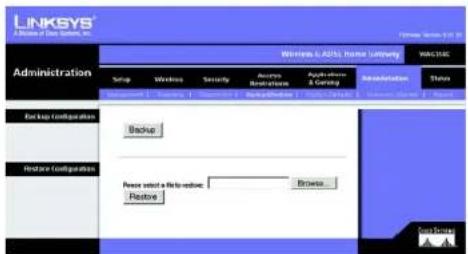
text_image
LINKSYS® A Division of Data Services, Inc. Administration Windows & AT&T Manager Lnting Setup Wireless Security Access Installation Applications & Currency Administration Status Backup Configurations Backup Restore Configurations Please select a file to restore: Restore Browse Browse... Browse... Browse... Browse... Browse... Browse... Browse... Browse... Browse... Browse... Browse... Browse... Browse... Browse... Browse... Browse... Browse... Browse... Browse... Browse... Browse... Browse... Browse... Browse... Browse... Browse... Browse... Browse... Browse... Browse... Browse... Browse... Browse... Browse... Browse... Browse... Browse... Browse... Browse... Browse... Browse... Browse... Browse... Browse... Browse... Browse... Browse... Browse... Browse... Browse... Browse...Figure 5-37: Backup&Restore
Wireless-G ADSL Home Gateway
The Factory Defaults Tab
Restore Factory Defaults. If you wish to restore the Gateway to its factory default settings and lose all your settings, click Yes.
To begin the restore process, click the Save Settings button to save these changes, or click the Cancel Changes button to undo your changes.
The Firmware Upgrade Tab
The Gateway allows you to upgrade firmware from the LAN (Local Area Network) side of the Gateway.
Upgrade from LAN
To upgrade the Gateway's firmware from the LAN:
- Download the Gateway's firmware upgrade file from www.linksys.com/international.
- Extract the file on your computer.
- Click the Browse button to find the firmware upgrade file.
- Double-click the firmware file that you have downloaded and extracted.
- Click the Upgrade button, and follow the on-screen instructions.
To cancel the firmware upgrade, click the Cancel Upgrades button.
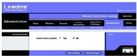
text_image
LINKSYS A Division of Data Systems, Inc. Administration Microsoft SQL Server Administration WAL-2016 Setup Windows Security Accounts Availability Platform Administration Value Management 1 Maintenance 2 Maintenance & Coding Factory Default Restore Factory Default: Yes No Save Settings Cancel Changes Next Gains ServicesFigure 5-38: Factory Defaults

text_image
LINKSYS A License of the Systems Inc. Administration Windows® ARM Travel Company Setup Wireless Security Access Applications Settings Applications Administration Status Upgrade Focus: A8 Firmware Upgrade File Park Drive Warning: Upgrading Firmware has far side may make a few minutes, please don't run off the power or press the social button. Upgrade less IBM to illustrate! Upgrade Cancel/Upgrade HelpFigure 5-39: Firmware Upgrade
Wireless-G ADSL Home Gateway
The Reboot Tab
This screen allows you to do a soft or hard reboot of the Gateway. In most cases you should use the hard reboot. The soft reboot is similar to restarting your computer without physically powering down the computer.
Reboot
Reboot Mode. To reboot your Gateway, select Hard or Soft. Choose Hard to power cycle the Gateway or Soft. to restart it without a power cycle.
To begin the reboot process, click the Save Settings button. When a screen appears asking you if you really want to reboot the Gateway, click OK.
Click the Cancel Changes button if you want to cancel the reboot.
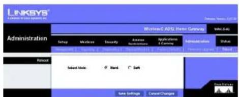
text_image
LINKSYS A Software in this system is Windows 6 ADS Server Gateway WAL-3.45 Administration Setup Services Security Access Access Resources Applications & Controls Administrators Status Amounts: 1, 2, 3, 4, 5, 6, 7, 8, 9, 10, 11, 12, 13, 14, 15, 16, 17, 18, 19, 20, 21, 22, 23, 24, 25, 26, 27, 28, 29, 30, 31, 32, 33, 34, 35, 36, 37, 38, 39, 40, 41, 42, 43, 44, 45, 46, 47, 48, 49, 50, 51, 52, 53, 54, 55, 56, 57, 58, 59, 60, 61, 62, 63, 64, 65, 66, 67, 68, 69, 70, 71, 72, 73, 74, 75, 76, 77, 78, 79, 80, 81, 82, 83, 84, 85, 86, 87, 88, 89, 90, 91, 92, 93, 94, 95, 96, 97, 98, 99, 100 Remote Risool Mode: Hard: Soft Save Settings Cancel Changes Free EnergyFigure 5-40: Reboot
Wireless-G ADSL Home Gateway
The Status Tab
The Gateway Tab
This screen displays information about the Gateway and its Internet connection.
Gateway Information
This section displays the Gateway's Firmware Version, MAC Address, and Current Time.
Internet Connection
This section shows the following information: the Connection, Login Type, Interface, IP Address, Subnet Mask, Default Gateway, DNS 1, 2, and 3 server IP addresses, and WINS address.
DHCP Renew. Click the DHCP Renew button to replace the Gateway's current IP address with a new IP address. DHCP Release. Click the DHCP Release button to delete the Gateway's current IP address.
Click the Refresh button if you want to refresh the displayed information.

text_image
LINKSYS J Server & Chat System, Inc. Status Wireless C: A857, Network Category: WACHS Setup Windows Security Access Network Access Applications ( Learning ) Administration Status Database Access Network Access Access Internet Internet Information Domestic/Inclusive: 841.06, Fax 16-0000 MAC Address: 99.80.66-AA-6-00 Current Type: Not Available Internal Connections Login Type: EMCP HostLine: Up P Address: 99.5478 Submit Mode: 256.206.256.8 Default Delivery: 99.5471 DNS 1: 206.1128.52 DNS 2: 206.1128.52 DNS 3: 8.8.8.8 WIND: DHCP-Database DHCP Review Refresh Win: Data Source: AFigure 5-41: Gateway
Wireless-G ADSL Home Gateway
The Local Network Tab
The Local Network information that is displayed is the local Mac Address, IP Address, Subnet Mask, DHCP Server, Start IP Address, and End IP Address. To view the DHCP Clients Table, click the DHCP Clients Table button. To view the ARP/RARP Table, click the ARP/RARP Table button.
DHCP Clients Table. The DHCP Active IP Table shows the current DHCP Client data. You will see the computer name, IP address, MAC address, and expiration time of the dynamic IP address for the wireless clients using the DHCP server. (This data is stored in temporary memory and changes periodically.) Click the Refresh button if you want to refresh the displayed information. To delete a client from the DHCP server, select the client, and then click the Delete button. Click the Close button to return to the Local Network screen.
ARP/RARP Table. The ARP/RARP Table shows the current data for the local network clients that have sent an ARP request to the Gateway. You will see their IP addresses and MAC addresses. (This data is stored in temporary memory and changes periodically.) An ARP request is a request sent by the Gateway asking clients with IP addresses for their MAC addresses, so the Gateway can map IP addresses to MAC addresses. RARP is the reverse of ARP. Click the Refresh button if you want to refresh the displayed information. Click the Close button to return to the Local Network screen.
Click the Refresh button if you want to refresh the displayed information.

text_image
LINKSYS A Website of Data Systems, Inc. Status Windows 6. ADSL Status Gateway Setup Windows Security Access Repetrations Applications S Trading Administration Status Local Network MAC Address: 90-95-68-AA-94-FT P Address: 192.08.1.1 Send Work: 253.25.251.8 DHCP Server: Enable Set P Address: 192.08.1.54 End P Address: 192.08.1.251 DHCP Clients Table AND/RARP Table NetworkFigure 5-42: Local Network
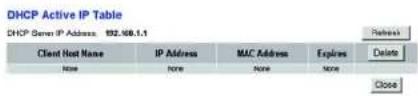
text_image
DHCP Active IP Table DHCP Server IP Address: 192.168.1.1 Client Host Name IP Address MAC Address Expires None None None None Delete CloseFigure 5-43: DHCP Active IP Table

Figure 5-44: ARP/RARP Table
Wireless-G ADSL Home Gateway
The Wireless Tab
The Wireless network information that is displayed is the Wireless Firmware Version, MAC Address, Mode, SSID, DHCP Server, Channel, and Encryption Function.
Click the Wireless Clients Connected button to view a list of the wireless clients connected to the Gateway, along with their computer names, IP addresses, and MAC addresses. Click the Refresh button if you want to refresh the displayed information. Click the Close button to return to the Wireless screen.
Click the Refresh button if you want to refresh the displayed information.

text_image
LINKSYS A class of data systems, Inc. Status Windows C:\ADRS\Waste\Locking Status Wireless Version: Status MAC Address: "Waste\Locking" Mode: Mixed SDD: Insges DHCP Server: Enable Channel: 0 Encryption Function: Shutdown Wireless Clients Connected MACHINE Access Auto... Return Next ProcessFigure 5-45: Wireless

text_image
Networked Computers Refresh Computer Name IP Address MAC Address CloseFigure 5-46: Networked Computers
Chapter 5: Configuring the Wireless-G ADSL Home Gateway The Status Tab
Wireless-G ADSL Home Gateway
The DSL Connection Tab
This screen shows information about the DSL connection and the PVC connection.
DSL Status
This section shows the following: DSL Status, DSL Modulation Mode, DSL Path Mode, Downstream Rate, Upstream Rate, Downstream Margin, Upstream Margin, Downstream Line Attenuation, Upstream Line Attenuation, Downstream Transmit Power, and Upstream Transmit Power.
PVC Connection
This section displays the following information: Encapsulation, Multiplexing, QoS, Pcr Rate, Scr Rate, Autodetect, VPI, VCI, Enable status, and PVC Status.
Click the Refresh button if you want to refresh the displayed information.

text_image
LINKSYS A License or Cus Incentives Status Setup Windows Security Active Applications Applications A Setting Administration DSL Status DSL Status RF DSL Modulation Mode F14F3 DSL Push Mode FAST Downstream Rate 9064.8bps Upstream Rate 9024.8bps Downstream Margin 53 db Upstream Margin 3 db Downstream Load Information: > Upstream Line Attenuation: | Downstream Transd Power: | Upstream Transd Power: | PVC Connection Extraculation 97C 140 (Shigged) Reliability LLC Geo IRR For Rate # For Rate # Autoreset Mobile VR # VO 3S Driver Yes PVC Status Applied - OK RefreshFigure 5-47: DSL Connection
Wireless-G ADSL Home Gateway
\*□□※■※■ \*□□◆○※▲※□□▼■※
This appendix consists of two parts: "Common Problems and Solutions" and "Frequently Asked Questions." Provided are possible solutions to problems that may occur during the installation and operation of the Gateway. Read the descriptions below to help you solve your problems. If you can't find an answer here, check the Linksys international website at www.linksys.com/international.
Common Problems and Solutions
1. I need to set a static IP address on a computer.
You can assign a static IP address to a computer by performing the following steps:
• For Windows 98 and Me:
- Click Start, Settings, and Control Panel. Double-click Network.
- In The following network components are installed box, select the TCP/IP-> associated with your Ethernet adapter. If you only have one Ethernet adapter installed, you will only see one TCP/IP line with no association to an Ethernet adapter. Highlight it and click the Properties button.
- In the TCP/IP properties window, select the IP address tab, and select Specify an IP address. Enter a unique IP address that is not used by any other computer on the network connected to the Gateway. Make sure that each IP address is unique for each computer or network device.
- Click the Gateway tab, and in the New Gateway prompt, enter 192.168.1.1, which is the default IP address of the Gateway. Click the Add button to accept the entry.
- Click the DNS tab, and make sure the DNS Enabled option is selected. Enter the Host and Domain names (e.g., John for Host and home for Domain). Enter the DNS entry provided by your ISP. If your ISP has not provided the DNS IP address, contact your ISP to get that information or go to its website for the information.
- Click the OK button in the TCP/IP properties window, and click Close or the OK button for the Network window.
- Restart the computer when asked.
- For Windows 2000:
- Click Start, Settings, and Control Panel. Double-click Network and Dial-Up Connections.
- Right-click the Local Area Connection that is associated with the Ethernet adapter you are using, and select the Properties option.
- In the Components checked are used by this connection box, highlight Internet Protocol (TCP/IP), and click the Properties button. Select Use the following IP address option.
- Enter a unique IP address that is not used by any other computer on the network connected to the Gateway.
- Enter the Subnet Mask, 255.255.255.0.
- Enter the Default Gateway, 192.168.1.1 (Gateway's default IP address).
Appendix A: Troubleshooting
Common Problems and Solutions
Wireless-G ADSL Home Gateway
- Toward the bottom of the window, select Use the following DNS server addresses, and enter the Preferred DNS server and Alternative DNS server (provided by your ISP). Contact your ISP or go on its website to find the information.
- Click the OK button in the Internet Protocol (TCP/IP) Properties window, and click the OK button in the Local Area Connection Properties window.
- Restart the computer if asked.
- For Windows XP:
The following instructions assume you are running Windows XP with the default interface. If you are using the Classic interface (where the icons and menus look like previous Windows versions), please follow the instructions for Windows 2000.
- Click Start and Control Panel.
- Click the Network and Internet Connections icon and then the Network Connections icon.
- Right-click the Local Area Connection that is associated with the Ethernet adapter you are using, and select the Properties option.
- In the This connection uses the following items box, highlight Internet Protocol (TCP/IP). Click the Properties button.
- Enter a unique IP address that is not used by any other computer on the network connected to the Gateway.
- Enter the Subnet Mask, 255.255.255.0.
- Enter the Default Gateway, 192.168.1.1 (Gateway's default IP address).
- Toward the bottom of the window, select Use the following DNS server addresses, and enter the Preferred DNS server and Alternative DNS server (provided by your ISP). Contact your ISP or go on its website to find the information.
- Click the OK button in the Internet Protocol (TCP/IP) Properties window. Click the OK button in the Local Area Connection Properties window.
2. I want to test my Internet connection.
A. Check your TCP/IP settings.
For Windows 98, Me, 2000, and XP:
• Refer to Windows Help for details. Make sure Obtain IP address automatically is selected in the settings.
For Windows NT 4.0:
- Click Start, Settings, and Control Panel. Double-click the Network icon.
- Click the Protocol tab, and double-click on TCP/IP Protocol.
- When the window appears, make sure you have selected the correct Adapter for your Ethernet adapter and set it for Obtain an IP address from a DHCP server.
- Click the OK button in the TCP/IP Protocol Properties window, and click the Close button in the Network window.
- Restart the computer if asked.
B. Open a command prompt.
Appendix A: Troubleshooting
Common Problems and Solutions
Wireless-G ADSL Home Gateway
For Windows 98 and Me:
- Click Start and Run. In the Open field, type in command. Press the Enter key or click the OK button.
For Windows NT, 2000, and XP:
- Click Start and Run. In the Open field, type cmd. Press the Enter key or click the OK button. In the command prompt, type ping 192.168.1.1 and press the Enter key.
- If you get a reply, the computer is communicating with the Gateway.
- If you do NOT get a reply, please check the cable, and make sure Obtain an IP address automatically is selected in the TCP/IP settings for your Ethernet adapter.
C. In the command prompt, type ping followed by your Internet or WAN IP address and press the Enter key. The Internet or WAN IP Address can be found on the Status screen of the Gateway's web-based utility. For example, if your Internet or WAN IP address is 1.2.3.4, you would enter ping 1.2.3.4 and press the Enter key.
- If you get a reply, the computer is connected to the Gateway.
- If you do NOT get a reply, try the ping command from a different computer to verify that your original computer is not the cause of the problem.
D. In the command prompt, type ping www.yahoo.com and press the Enter key.
- If you get a reply, the computer is connected to the Internet. If you cannot open a webpage, try the ping command from a different computer to verify that your original computer is not the cause of the problem.
- If you do NOT get a reply, there may be a problem with the connection. Try the ping command from a different computer to verify that your original computer is not the cause of the problem.
3. I am not getting an IP address on the Internet with my Internet connection.
- Refer to "Problem #2, I want to test my Internet connection" to verify that you have connectivity.
-
Make sure you are using the right Internet connection settings. Contact your ISP to see if your Internet connection type is RFC 1483 Bridged, RFC 1483 Routed, RFC 2516 PPPoE, or RFC 2364 PPPoA. Please refer to the Setup section of "Chapter 5: Configuring the Wireless-G ADSL Home Gateway" for details on Internet connection settings.
-
Make sure you have the right cable. Check to see if the Gateway column has a solidly lit ADSL LED.
-
Make sure the cable connecting from your Gateway's ADSL port is connected to the wall jack of the ADSL service line. Verify that the Status page of the Gateway's web-based utility shows a valid IP address from your ISP.
-
Turn off the computer and Gateway. Wait 30 seconds, and then turn on the Gateway, and computer. Check the Status tab of the Gateway's web-based utility to see if you get an IP address.
4. I am not able to access the Setup page of the Gateway's web-based utility.
- Refer to "Problem #2, I want to test my Internet connection" to verify that your computer is properly connected to the Gateway.
-
Refer to "Appendix C: Finding the MAC Address and IP address for Your Ethernet Adapter" to verify that your computer has an IP Address, Subnet Mask, Gateway, and DNS.
-
Set a static IP address on your system; refer to "Problem #1: I need to set a static IP address."
Appendix A: Troubleshooting
Common Problems and Solutions
Wireless-G ADSL Home Gateway
- Refer to "Problem #10: I am a PPPoE user, and I need to remove the proxy settings or the dial-up pop-up window."
5. I can't get my Virtual Private Network (VPN) working through the Gateway.
Access the Gateway's web interface by going to http://192.168.1.1 or the IP address of the Gateway, and go to the Security tab. Make sure you have IPsec passthrough and/or PPTP pass-through enabled.
- VPNs that use IPSec with the ESP (Encapsulation Security Payload known as protocol 50) authentication will work fine. At least one IPSec session will work through the Gateway; however, simultaneous IPSec sessions may be possible, depending on the specifics of your VPNs.
- VPNs that use IPSec and AH (Authentication Header known as protocol 51) are incompatible with the Gateway. AH has limitations due to occasional incompatibility with the NAT standard.
- Change the IP address for the Gateway to another subnet to avoid a conflict between the VPN IP address and your local IP address. For example, if your VPN server assigns an IP address 192.168.1.X (X is a number from 1 to 254) and your local LAN IP address is 192.168.1.X (X is the same number used in the VPN IP address), the Gateway will have difficulties routing information to the right location. If you change the Gateway's IP address to 192.168.2.1, that should solve the problem. Change the Gateway's IP address through the Setup tab of the web interface.
- If you assigned a static IP address to any computer or network device on the network, you need to change its IP address accordingly to 192.168.2.Y (Y being any number from 1 to 254). Note that each IP address must be unique within the network.
- Your VPN may require port 500/UDP packets to be passed to the computer that is connecting to the IPSec server. Refer to "Problem #7, I need to set up online game hosting or use other Internet applications" for details.
- Check the Linksys international website for more information at www.linksys.com/international.
6. I need to set up a server behind my Gateway and make it available to the public.
To use a server like a web, ftp, or mail server, you need to know the respective port numbers they are using. For example, port 80 (HTTP) is used for web; port 21 (FTP) is used for FTP, and port 25 (SMTP outgoing) and port 110 (POP3 incoming) are used for the mail server. You can get more information by viewing the documentation provided with the server you installed.
- Follow these steps to set up port forwarding through the Gateway's web-based utility. We will be setting up web, ftp, and mail servers.
- Access the Gateway's web-based utility by going to http://192.168.1.1 or the IP address of the Gateway. Go to the Applications and Gaming => Port Range Forwarding tab.
- Enter any name you want to use for the Customized Application.
- Enter the External Port range of the service you are using. For example, if you have a web server, you would enter the range 80 to 80.
- Check the protocol you will be using, TCP and/or UDP.
- Enter the IP address of the computer or network device that you want the port server to go to. For example, if the web server's Ethernet adapter IP address is 192.168.1.100, you would enter 100 in the
Appendix A: Troubleshooting
Common Problems and Solutions
Wireless-G ADSL Home Gateway
field provided. Check "Appendix C: Finding the MAC Address and IP Address for Your Ethernet Adapter" for details on getting an IP address.
- Check the Enable option for the port services you want to use. Consider the example below:
Customized Application External Port TCP UDP IP Address Enable
Web server 80 to 80 X 192.168.1.100 X
FTP server 21 to 21 X 192.168.1.101 X
SMTP (outgoing) 25 to 25 X 192.168.1.102 X
POP3 (incoming) 110 to 110 X 192.168.1.102 X
When you have completed the configuration, click the Save Settings button.
7. I need to set up online game hosting or use other Internet applications.
If you want to play online games or use Internet applications, most will work without doing any port forwarding or DMZ hosting. There may be cases when you want to host an online game or Internet application. This would require you to set up the Gateway to deliver incoming packets or data to a specific computer. This also applies to the Internet applications you are using. The best way to get the information on what port services to use is to go to the website of the online game or application you want to use. Follow these steps to set up online game hosting or use a certain Internet application:
- Access the Gateway's web interface by going to http://192.168.1.1 or the IP address of the Gateway. Go to the Applications and Gaming => Port Range Forwarding tab.
- Enter any name you want to use for the Customized Application.
- Enter the External Port range of the service you are using. For example, if you want to host Unreal Tournament (UT), you would enter the range 7777 to 27900.
- Check the protocol you will be using, TCP and/or UDP.
- Enter the IP address of the computer or network device that you want the port server to go to. For example, if the web server's Ethernet adapter IP address is 192.168.1.100, you would enter 100 in the field provided. Check "Appendix C: Finding the MAC Address and IP Address for Your Ethernet Adapter" for details on getting an IP address.
- Check the Enable option for the port services you want to use. Consider the example below:
| Customized Application | External Port | TCP | UDP | IP Address | Enable |
| UT | 7777 to 27900 | X | X | 192.168.1.100 | X |
| Halflife | 27015 to 27015 | X | X | 192.168.1.105 | X |
| PC Anywhere | 5631 to 5631 | X | 192.168.1.102 | X | |
| VPN IPSEC | 500 to 500 | X | 192.168.1.100 | X |
When you have completed the configuration, click the Save Settings button.
Wireless-G ADSL Home Gateway
8. I can't get the Internet game, server, or application to work.
If you are having difficulties getting any Internet game, server, or application to function properly, consider exposing one computer to the Internet using DeMilitarized Zone (DMZ) hosting. This option is available when an application requires too many ports or when you are not sure which port services to use. Make sure you disable all the forwarding entries if you want to successfully use DMZ hosting, since forwarding has priority over DMZ hosting. (In other words, data that enters the Gateway will be checked first by the forwarding settings. If the port number that the data enters from does not have port forwarding, then the Gateway will send the data to whichever computer or network device you set for DMZ hosting.)
• Follow these steps to set DMZ hosting:
-
Access the Gateway's web-based utility by going to http://192.168.1.1 or the IP address of the Gateway. Go to the Applications and Gaming => DMZ tab. Click Enabled and enter the IP of the computer.
-
Check the Port Forwarding pages and disable or remove the entries you have entered for forwarding. Keep this information in case you want to use it at a later time.
- Once completed with the configuration, click the Save Settings button.
9. I forgot my password, or the password prompt always appears when I am saving settings to the Gateway.
- Reset the Gateway to factory default by pressing the Reset button for 10 seconds and then releasing it. If you are still getting prompted for a password when saving settings, then perform the following steps:
-
Access the Gateway's web-based utility by going to http://192.168.1.1 or the IP address of the Gateway. Enter the default username and password admin, and click the Administrations => Management tab.
-
Enter a different password in the Gateway Password field, and enter the same password in the second field to confirm the password.
-
Click the Save Settings button.
10. I am a PPPoE user, and I need to remove the proxy settings or the dial-up pop-up window.
If you have proxy settings, you need to disable these on your computer. Because the Gateway is the gateway for the Internet connection, the computer does not need any proxy settings to gain access. Please follow these directions to verify that you do not have any proxy settings and that the browser you use is set to connect directly to the LAN.
- For Microsoft Internet Explorer 5.0 or higher:
-
Click Start, Settings, and Control Panel. Double-click Internet Options.
-
Click the Connections tab.
-
Click the LAN settings button and remove anything that is checked.
-
Click the OK button to go back to the previous screen.
-
Click the option Never dial a connection. This will remove any dial-up pop-ups for PPPoE users.
Appendix A: Troubleshooting
Common Problems and Solutions
Wireless-G ADSL Home Gateway
• For Netscape 6 or higher:
- Start Netscape Navigator, and click Edit, Preferences, Advanced, and Proxies.
- Make sure you have Direct connection to the Internet selected on this screen.
- Close all the windows to finish.
11. To start over, I need to set the Gateway to factory default.
Hold the Reset button for 10 seconds and then release it. This will return the Internet settings, password, forwarding, and other settings on the Gateway to the factory default settings. In other words, the Gateway will revert to its original factory configuration.
12. I need to upgrade the firmware.
In order to upgrade the firmware with the latest features, you need to go to the Linksys international website and download the latest firmware at www.linksys.com/international.
- Follow these steps:
- Go to the Linksys international website at http://www.linksys.com/international and select your region or country.
- Click the Products tab and select the Gateway.
- On the Gateway's webpage, click Firmware, and then download the latest firmware for the Gateway.
- To upgrade the firmware, follow the steps in the Administration section found in "Chapter 5: Configuring the Wireless-G ADSL Home Gateway."
13. The firmware upgrade failed, and/or the Power LED is flashing.
The upgrade could have failed for a number of reasons. Follow these steps to upgrade the firmware and/or make the Power LED stop flashing:
- If the firmware upgrade failed, use the TFTP program (it was downloaded along with the firmware). Open the pdf that was downloaded along with the firmware and TFTP program, and follow the pdf's instructions.
- Set a static IP address on the computer; refer to "Problem #1, I need to set a static IP address." Use the following IP address settings for the computer you are using:
IP Address: 192.168.1.50
Subnet Mask: 255.255.255.0
Gateway: 192.168.1.1
- Perform the upgrade using the TFTP program or the Gateway's web-based utility through its Administration tab.
14. My DSL service's PPPoE is always disconnecting.
PPPoE is not actually a dedicated or always-on connection. The DSL ISP can disconnect the service after a period of inactivity, just like a normal phone dial-up connection to the Internet.
- There is a setup option to "keep alive" the connection. This may not always work, so you may need to re-establish connection periodically.
Appendix A: Troubleshooting
Common Problems and Solutions
Wireless-G ADSL Home Gateway
- To connect to the Gateway, go to the web browser, and enter http://192.168.1.1 or the IP address of the Gateway.
- Enter the username and password, if asked. (The default username and password is admin.)
- On the Setup screen, select the option Keep Alive, and set the Redial Period option at 20 (seconds).
- Click the Save Settings button. Click the Status tab, and click the Connect button.
- You may see the login status display as Connecting. Press the F5 key to refresh the screen, until you see the login status display as Connected.
- Click the Save Settings button to continue.
- If the connection is lost again, follow steps 1-6 to re-establish connection.
15. I can't access my e-mail, web, or VPN, or I am getting corrupted data from the Internet.
The Maximum Transmission Unit (MTU) setting may need to be adjusted. By default, the MTU is set automatically.
- If you are having some difficulties, perform the following steps:
- To connect to the Gateway, go to the web browser, and enter http://192.168.1.1 or the IP address of the Gateway.
- Enter the username and password, if asked. (The default username and password is admin.)
- Look for the MTU option, and select Manual. In the Size field, enter 1492.
- Click the Save Settings button to continue.
- If your difficulties continue, change the Size to different values. Try this list of values, one value at a time, in this order, until your problem is solved:
1462
1400
1362
1300
16. The Power LED flashes continuously.
The Power LED lights up when the device is first powered up. In the meantime, the system will boot up itself and check for proper operation. After finishing the checking procedure, the LED remains steady to show that the system is working fine. If the LED continues to flash after this time, the device is not working properly. Try to flash the firmware by assigning a static IP address to the computer, and then upgrade the firmware. Try using the following settings, IP Address: 192.168.1.50 and Subnet Mask: 255.255.255.0.
17. When I enter a URL or IP address, I get a time-out error or am prompted to retry.
- Check if other computers work. If they do, ensure that your computer's IP settings are correct (IP Address, Subnet Mask, Default Gateway, and DNS). Restart the computer that is having a problem.
- If the computers are configured correctly, but still not working, check the Gateway. Ensure that it is connected and powered on. Connect to it and check its settings. (If you cannot connect to it, check the LAN and power connections.)
Wireless-G ADSL Home Gateway
- If the Gateway is configured correctly, check your Internet connection (DSL/cable modem, etc.) to see if it is working correctly. You can remove the Gateway to verify a direct connection.
- Manually configure the TCP/IP settings with a DNS address provided by your ISP.
- Make sure that your browser is set to connect directly and that any dial-up is disabled. For Internet Explorer, click Tools, Internet Options, and then the Connection tab. Make sure that Internet Explorer is set to Never dial a connection. For Netscape Navigator, click Edit, Preferences, Advanced, and Proxy. Make sure that Netscape Navigator is set to Direct connection to the Internet.
18. I'm trying to access the Gateway's Web-based Utility, but I do not see the login screen. Instead, I see a screen saying, "404 Forbidden."
If you are using Windows Explorer, perform the following steps until you see the Web-based Utility's login screen (Netscape Navigator will require similar steps):
-
Click File. Make sure Work Offline is NOT checked.
-
Press CTRL + F5. This is a hard refresh, which will force Windows Explorer to load new webpages, not cached ones.
- Click Tools. Click Internet Options. Click the Security tab. Click the Default level button. Make sure the security level is Medium or lower. Then click the OK button.
Frequently Asked Questions
What is the maximum number of IP addresses that the Gateway will support?
The Gateway will support up to 253 IP addresses.
Is IPSec Passthrough supported by the Gateway?
Yes, it is a built-in feature that is enabled by default.
Where is the Gateway installed on the network?
In a typical environment, the Gateway is installed between the ADSL wall jack and the LAN.
Does the Gateway support IPX or AppleTalk?
No. TCP/IP is the only protocol standard for the Internet and has become the global standard for communications. IPX, a NetWare communications protocol used only to route messages from one node to another, and AppleTalk, a communications protocol used on Apple and Macintosh networks, can be used for LAN to LAN connections, but those protocols cannot connect from the Internet to a LAN.
Does the LAN connection of the Gateway support 100Mbps Ethernet?
The Gateway supports 100Mbps over the auto-sensing Fast Ethernet 10/100 switch on the LAN side of the Gateway.
Appendix A: Troubleshooting
Frequently Asked Questions
Wireless-G ADSL Home Gateway
What is Network Address Translation and what is it used for?
Network Address Translation (NAT) translates multiple IP addresses on the private LAN to one public address that is sent out to the Internet. This adds a level of security since the address of a computer connected to the private LAN is never transmitted on the Internet. Furthermore, NAT allows the Gateway to be used with low cost Internet accounts when only one TCP/IP address is provided by the ISP. The user may have many private addresses behind this single address provided by the ISP.
Does the Gateway support any operating system other than Windows 98SE, Windows Millennium, Windows 2000, or Windows XP?
Yes, but Linksys does not, at this time, provide technical support for setup, configuration or troubleshooting of any non-Windows operating systems.
Does the Gateway support ICQ send file?
Yes, with the following fix: click ICQ menu -> preference -> connections tab->, and check I am behind a firewall or proxy. Then set the firewall time-out to 80 seconds in the firewall setting. The Internet user can then send a file to a user behind the Gateway.
I set up an Unreal Tournament Server, but others on the LAN cannot join. What do I need to do?
If you have a dedicated Unreal Tournament server running, you need to create a static IP for each of the LAN computers and forward ports 7777, 7778, 7779, 7780, 7781, and 27900 to the IP address of the server. You can also use a port forwarding range of 7777 \~ 27900. If you want to use the UT Server Admin, forward another port (Port 8080 usually works well but is used for remote admin. You may have to disable this.) Then in the [UWeb.WebServer] section of the server.ini file, set the ListenPort to 8080 (to match the mapped port above) and ServerName to the IP assigned to the Gateway from your ISP.
Can multiple gamers on the LAN get on one game server and play simultaneously with just one public IP address?
It depends on which network game or what kind of game server you are using. For example, Unreal Tournament supports multi-login with one public IP.
How do I get Half-Life: Team Fortress to work with the Gateway?
The default client port for Half-Life is 27005. The computers on your LAN need to have "+clientport 2700x" added to the HL shortcut command line; the x would be 6, 7, 8, and on up. This lets multiple computers connect to the same server. One problem: Version 1.0.1.6 won't let multiple computers with the same CD key connect at the same time, even if on the same LAN (not a problem with 1.0.1.3). As far as hosting games, the HL server does not need to be in the DMZ. Just forward port 27015 to the local IP address of the server computer.
Appendix A: Troubleshooting
Frequently Asked Questions
Wireless-G ADSL Home Gateway
The web page hangs; downloads are corrupt, or nothing but junk characters are being displayed on the screen. What do I need to do?
Force your Ethernet adapter to 10Mbps or half duplex mode, and turn off the "Auto-negotiate" feature of your Ethernet adapter as a temporary measure. (Please look at the Network Control Panel in your Ethernet adapter's Advanced Properties tab.) Make sure that your proxy setting is disabled in the browser. Check our website at www.linksys.com/international for more information.
If all else fails in the installation, what can I do?
Reset the Gateway by holding down the reset button until the Power LED fully turns on and off. Reset your DSL modem by powering the unit off and then on. Obtain and flash the latest firmware release that is readily available on the Linksys international website, www.linksys.com/international.
How will I be notified of new Gateway firmware upgrades?
All Linksys firmware upgrades are posted on the Linksys international website at www.linksys.com/international, where they can be downloaded for free. To upgrade the Gateway's firmware, use the Administration tab of the Gateway's web-based utility. If the Gateway's Internet connection is working well, there is no need to download a newer firmware version, unless that version contains new features that you would like to use.
Will the Gateway function in a Macintosh environment?
Yes, but the Gateway's setup pages are accessible only through Internet Explorer 4.0 or Netscape Navigator 4.0 or higher for Macintosh.
I am not able to get the web configuration screen for the Gateway. What can I do?
You may have to remove the proxy settings on your Internet browser, e.g., Netscape Navigator or Internet Explorer. Check with your browser documentation, and make sure that your browser is set to connect directly and that any dial-up is disabled. For Internet Explorer, click Tools, Internet Options, and then the Connection tab. Make sure that Internet Explorer is set to Never dial a connection. For Netscape Navigator, click Edit, Preferences, Advanced, and Proxy. Make sure that Netscape Navigator is set to Direct connection to the Internet.
What is DMZ Hosting?
Demilitarized Zone (DMZ) allows one IP address (computer) to be exposed to the Internet. Some applications require multiple TCP/IP ports to be open. It is recommended that you set your computer with a static IP if you want to use DMZ Hosting. To get the LAN IP address, see "Appendix C: Finding the MAC Address and IP Address for Your Ethernet Adapter."
If DMZ Hosting is used, does the exposed user share the public IP with the Gateway?
No.
Does the Gateway pass PPTP packets or actively route PPTP sessions?
The Gateway allows PPTP packets to pass through.
Appendix A: Troubleshooting
Frequently Asked Questions
Wireless-G ADSL Home Gateway
Is the Gateway cross-platform compatible?
Any platform that supports Ethernet and TCP/IP is compatible with the Gateway.
How many ports can be simultaneously forwarded?
Theoretically, the Gateway can establish 520 sessions at the same time, but you can only forward 10 ranges of ports.
What are the advanced features of the Gateway?
The Gateway's advanced features include Advanced Wireless settings, Filters, Port Forwarding, Routing, and DDNS.
What is the maximum number of VPN sessions allowed by the Gateway?
The maximum number depends on many factors. At least one IPSec session will work through the Gateway; however, simultaneous IPSec sessions may be possible, depending on the specifics of your VPNs.
How can I check whether I have static or DHCP IP Addresses?
Consult your ISP to obtain this information.
How do I get mIRC to work with the Gateway?
Under the Port Forwarding tab, set port forwarding to 113 for the computer on which you are using mIRC.
Can the Gateway act as my DHCP server?
Yes. The Gateway has DHCP server software built-in.
Can I run an application from a remote computer over the wireless network?
This will depend on whether or not the application is designed to be used over a network. Consult the application's documentation to determine if it supports operation over a network.
What is the IEEE 802.11g standard?
It is one of the IEEE standards for wireless networks. The 802.11g standard allows wireless networking hardware from different manufacturers to communicate, provided that the hardware complies with the 802.11g standard. The 802.11g standard states a maximum data transfer rate of 54Mbps and an operating frequency of 2.4GHz.
Appendix A: Troubleshooting
Frequently Asked Questions
Wireless-G ADSL Home Gateway
What IEEE 802.11b and 802.11g features are supported?
The product supports the following IEEE 802.11b and IEEE 802.11g functions:
• CSMA/CA plus Acknowledge protocol
• Multi-Channel Roaming
• Automatic Rate Selection
- RTS/CTS feature
- Fragmentation
• Power Management
It also supports OFDM technology for 802.11g networking.
What is ad-hoc mode?
When a wireless network is set to ad-hoc mode, the wireless-equipped computers are configured to communicate directly with each other, peer-to-peer without the use of an access point.
What is infrastructure mode?
When a wireless network is set to infrastructure mode, the wireless network is configured to communicate with a network through a wireless access point.
What is roaming?
Roaming is the ability of a portable computer user to communicate continuously while moving freely throughout an area greater than that covered by a single access point. Before using the roaming function, the computer must make sure that it is the same channel number with the access point of dedicated coverage area.
To achieve true seamless connectivity, the wireless LAN must incorporate a number of different functions. Each node and access point, for example, must always acknowledge receipt of each message. Each node must maintain contact with the wireless network even when not actually transmitting data. Achieving these functions simultaneously requires a dynamic RF networking technology that links access points and nodes. In such a system, the user's end node undertakes a search for the best possible access to the system. First, it evaluates such factors as signal strength and quality, as well as the message load currently being carried by each access point and the distance of each access point to the wired backbone. Based on that information, the node next selects the right access point and registers its address. Communications between end node and host computer can then be transmitted up and down the backbone.
As the user moves on, the end node's RF transmitter regularly checks the system to determine whether it is in touch with the original access point or whether it should seek a new one. When a node no longer receives acknowledgment from its original access point, it undertakes a new search. Upon finding a new access point, it then re-registers, and the communication process continues.
Appendix A: Troubleshooting
Frequently Asked Questions
Wireless-G ADSL Home Gateway
What is the ISM band?
The FCC and their counterparts outside of the U.S. have set aside bandwidth for unlicensed use in the ISM (Industrial, Scientific and Medical) band. Spectrum in the vicinity of 2.4 GHz, in particular, is being made available worldwide. This presents a truly revolutionary opportunity to place convenient high-speed wireless capabilities in the hands of users around the globe.
What is Spread Spectrum?
Spread Spectrum technology is a wideband radio frequency technique developed by the military for use in reliable, secure, mission-critical communications systems. It is designed to trade off bandwidth efficiency for reliability, integrity, and security. In other words, more bandwidth is consumed than in the case of narrowband transmission, but the trade-off produces a signal that is, in effect, louder and thus easier to detect, provided that the receiver knows the parameters of the spread-spectrum signal being broadcast. If a receiver is not tuned to the right frequency, a spread-spectrum signal looks like background noise. There are two main alternatives, Direct Sequence Spread Spectrum (DSSS) and Frequency Hopping Spread Spectrum (FHSS).
What is DSSS? What is FHSS? And what are their differences?
Frequency-Hopping Spread-Spectrum (FHSS) uses a narrowband carrier that changes frequency in a pattern that is known to both transmitter and receiver. Properly synchronized, the net effect is to maintain a single logical channel. To an unintended receiver, FHSS appears to be short-duration impulse noise. Direct-Sequence Spread-Spectrum (DSSS) generates a redundant bit pattern for each bit to be transmitted. This bit pattern is called a chip (or chipping code). The longer the chip, the greater the probability that the original data can be recovered. Even if one or more bits in the chip are damaged during transmission, statistical techniques embedded in the radio can recover the original data without the need for retransmission. To an unintended receiver, DSSS appears as low power wideband noise and is rejected (ignored) by most narrowband receivers.
Will the information be intercepted while it is being transmitted through the air?
WLAN features two-fold protection in security. On the hardware side, as with Direct Sequence Spread Spectrum technology, it has the inherent security feature of scrambling. On the software side, WLAN offers the encryption function (WEP) to enhance security and access control.
What is WEP?
WEP is Wired Equivalent Privacy, a data privacy mechanism based on a 64-bit or 128-bit shared key algorithm, as described in the IEEE 802.11 standard.
What is a MAC Address?
The Media Access Control (MAC) address is a unique number assigned by the manufacturer to any Ethernet networking device, such as a network adapter, that allows the network to identify it at the hardware level. For all practical purposes, this number is usually permanent. Unlike IP addresses, which can change every time a computer logs onto the network, the MAC address of a device stays the same, making it a valuable identifier for the network.
Appendix A: Troubleshooting
Frequently Asked Questions
Wireless-G ADSL Home Gateway
How do I reset the Gateway?
Press the Reset button on the back panel for about ten seconds. This will reset the Gateway to its default settings.
How do I resolve issues with signal loss?
There is no way to know the exact range of your wireless network without testing. Every obstacle placed between the Gateway and a wireless computer will create signal loss. Lead glass, metal, concrete floors, water and walls will inhibit the signal and reduce range. Start with the Gateway and your wireless computer in the same room and move it away in small increments to determine the maximum range in your environment.
You may also try using different channels, as this may eliminate interference affecting only one channel.
I have excellent signal strength, but I cannot see my network.
WEP is probably enabled on the Gateway, but not on your wireless adapter (or vice versa). Verify that the same WEP keys and levels (64 or 128) are being used on all nodes of your wireless network.
How many channels/frequencies are available with the Gateway?
There are eleven available channels, ranging from 1 to 11, in North America. There may be additional channels available in other regions, subject to the regulations of your region and/or country.
If your questions are not addressed here, refer to the Linksys international website, www.linksys.com/international.
Wireless-G ADSL Home Gateway
\*□□■■■+★□□□▲\*\*◆□▼
Linksys wants to make wireless networking as safe and easy for you as possible. The current generation of Linksys products provide several network security features, but they require specific action on your part for implementation. So, keep the following in mind whenever you are setting up or using your wireless network.
Security Precautions
The following is a complete list of security precautions to take (at least steps 1 through 5 should be followed):
- Change the default SSID.
- Disable SSID Broadcast.
- Change the default password for the Administrator account.
- Enable MAC Address Filtering.
- Change the SSID periodically.
- Use the highest encryption algorithm possible. Use WPA if it is available. Please note that this may reduce your network performance.
- Change the WEP encryption keys periodically.
For information on implementing these security features, refer to “Chapter 6: Configuring the Wireless-G ADSL Home Gateway.”
Security Threats Facing Wireless Networks
Wireless networks are easy to find. Hackers know that in order to join a wireless network, wireless networking products first listen for "beacon messages". These messages can be easily decrypted and contain much of the network's information, such as the network's SSID (Service Set Identifier). Here are the steps you can take:
Change the administrator's password regularly. With every wireless networking device you use, keep in mind that network settings (SSID, WEP keys, etc.) are stored in its firmware. Your network administrator is the only person who can change network settings. If a hacker gets a hold of the administrator's password, he, too, can change those settings. So, make it harder for a hacker to get that information. Change the administrator's password regularly.
Appendix B: Wireless Security Security Precautions

NOTE: Some of these security features are available only through the network gateway, router, or access point. Refer to the gateway, router, or access point's documentation for more information.
Wireless-G ADSL Home Gateway
SSID. There are several things to keep in mind about the SSID:
-
Disable Broadcast
-
Make it unique
-
Change it often
Most wireless networking devices will give you the option of broadcasting the SSID. While this option may be more convenient, it allows anyone to log into your wireless network. This includes hackers. So, don't broadcast the SSID.
Wireless networking products come with a default SSID set by the factory. (The Linksys default SSID is "linksys".) Hackers know these defaults and can check these against your network. Change your SSID to something unique and not something related to your company or the networking products you use.
Change your SSID regularly so that any hackers who have gained access to your wireless network will have to start from the beginning in trying to break in.
MAC Addresses. Enable MAC Address filtering. MAC Address filtering will allow you to provide access to only those wireless nodes with certain MAC Addresses. This makes it harder for a hacker to access your network with a random MAC Address.
WEP Encryption. Wired Equivalent Privacy (WEP) is often looked upon as a cure-all for wireless security concerns. This is overstating WEP's ability. Again, this can only provide enough security to make a hacker's job more difficult.
There are several ways that WEP can be maximized:
-
Use the highest level of encryption possible
-
Use "Shared Key" authentication
-
Change your WEP key regularly
WPA. Wi-Fi Protected Access (WPA) is the newest and best available standard in Wi-Fi security. Two modes are available: Pre-Shared Key and RADIUS. Pre-Shared Key gives you a choice of two encryption methods: TKIP (Temporal Key Integrity Protocol), which utilizes a stronger encryption method and incorporates Message Integrity Code (MIC) to provide protection against hackers, and AES (Advanced Encryption System), which utilizes a symmetric 128-Bit block data encryption. RADIUS (Remote Authentication Dial-In User Service) utilizes a RADIUS server for authentication and the use of dynamic TKIP, AES, or WEP.

IMPORTANT: Always remember that each device in your wireless network MUST use the same encryption method and encryption key or your wireless network will not function properly.
Appendix B: Wireless Security
Security Threats Facing Wireless Networks
Wireless-G ADSL Home Gateway
WPA Pre-Shared Key. If you do not have a RADIUS server, Select the type of algorithm, TKIP or AES, enter a password in the Pre-Shared key field of 8-64 characters, and enter a Group Key Renewal period time between 0 and 99,999 seconds, which instructs the Gateway or other device how often it should change the encryption keys.
WPA RADIUS. WPA used in coordination with a RADIUS server. (This should only be used when a RADIUS server is connected to the Gateway or other device.) First, select the type of WPA algorithm, TKIP or AES. Enter the RADIUS server's IP Address and port number, along with a key shared between the device and the server. Last, enter a Group Key Renewal period, which instructs the device how often it should change the encryption keys.
RADIUS. WEP used in coordination with a RADIUS server. (This should only be used when a RADIUS server is connected to the Gateway or other device.) First, enter the RADIUS server's IP Address and port number, along with a key shared between the device and the server. Then, select a WEP key and a level of WEP encryption, and either generate a WEP key through the Passphrase or enter the WEP key manually.
Implementing encryption may have a negative impact on your network's performance, but if you are transmitting sensitive data over your network, encryption should be used.
These security recommendations should help keep your mind at ease while you are enjoying the most flexible and convenient technology Linksys has to offer.
Wireless-G ADSL Home Gateway

text_image
Collection of symbolic and stylized icons including stars, asterisks, and symbols in black, white, and red.This section describes how to find the MAC address for your computer's Ethernet adapter so you can use the MAC filtering feature of the Gateway. You can also find the IP address of your computer's Ethernet adapter. This IP address is used for the Gateway's filtering, forwarding, and/or DMZ features. Follow the steps in this appendix to find the adapter's MAC or IP address in Windows 98, Me, 2000, or XP.
Windows 98 or Me Instructions
- Click Start and Run. In the Open field, enter winipcfg. Then press the Enter key or the OK button.
- When the IP Configuration screen appears, select the Ethernet adapter you have connected to the Gateway via a CAT 5 Ethernet network cable. See Figure C-1.
- Write down the Adapter Address as shown on your computer screen (see Figure C-2). This is the MAC address for your Ethernet adapter and is shown in hexadecimal as a series of numbers and letters.
The MAC address/Adapter Address is what you will use for MAC filtering. The example in Figure D-2 shows the Ethernet adapters's MAC address as 00-00-00-00-00-00. Your computer will show something different.
The example in Figure C-2 shows the Ethernet adapter's IP address as 192.168.1.100. Your computer may show something different.

Note: The MAC address is also called the Adapter Address.
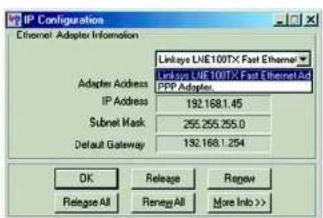
text_image
IP Configuration Ethernet Adaptor Information Linkages LIME100TX Fast Ethernet Linkages LIME 100TX Fast Ethernet Ad PPP Adaptor Adapters Address IP Address 192.168.1.45 Subnet Mask 255.255.255.0 Default Gateway 192.168.1.254 OK Release Review Release All Rename All More Info >>Figure C-1: IP Configuration Screen

text_image
IP Configuration Ethernet Adapter Information Linkeye LINE100TX Fast Ethernet Adapter Address 00:00:00:00:00 IP Address 192.168.1.10C Subnet Mask 255.255.255.0 Default Gateway 192.168.1.1 OK Release Repeat Release All Rename All More Info >>Figure C-2: MAC Address/Adapter Address
Appendix C: Finding the MAC Address and IP Address for Your Ethernet Adapter Windows 98 or Me Instructions
Wireless-G ADSL Home Gateway
Windows 2000 or XP Instructions
- Click Start and Run. In the Open field, enter cmd. Press the Enter key or click the OK button.

Note: The MAC address is also called the Physical Address.
- At the command prompt, enter ipconfig /all. Then press the Enter key.
- Write down the Physical Address as shown on your computer screen (Figure C-3); it is the MAC address for your Ethernet adapter. This appears as a series of numbers and letters.
The MAC address/Physical Address is what you will use for MAC filtering. The example in Figure C-3 shows the Ethernet adapters's MAC address as 00-00-00-00-00-00. Your computer will show something different.
The example in Figure C-3 shows the Ethernet adapter's IP address as 192.168.1.100. Your computer may show something different.
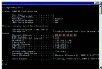
text_image
Windows 2000 IP Configuration Port Name : . . . . . . . . . . . . . . . . . . . . . . . . . . . . . . . . . . . . . . . . . . . . . . . . . . . . . . . . . . . . . . . . . . . . . . . . . . . . . . . Primary DNC Cuffix : . . . . . . . . . . . . . . . . . . . . . . . . . . . . . . . . . . . . . . . . . . . . . . . . . . . . . . . Type Type : 1.0000 Hybrid IP Backlog Enabled : 1.0000 No UING Proxy Enabled : 1.0000 No (Internet adapter Local New Connection) Connection specific DNC Cuffix : 1 Linker: UIC1000(No) Fast Ethernet 0 Physical Address : 100.00.00.00.00.00 UDP Enabled : Yes Microcontroller Linked : 197.168.1.1.00 IP Address : 197.168.1.1.00 Server: Backs : 197.168.1.1.00 Device Gateway : 197.168.1.1.00 UDP Server : 197.168.1.1.00 DNS Server : 197.168.1.1.00 Primary UIC5 Server : 197.168.1.1 Secondary UIC5 Server : Monday, February 11, 2002 2:31:47 PM Lease Enabled : Monday, February 11, 2002 2:31:47 PM Lease Options : Monday, February 11, 2002 2:31:47 PMFigure C-3: MAC Address/Physical Address
Wireless-G ADSL Home Gateway
\*□□※■※■◆+※□※□※※■◆□○○○○※
To upgrade the Gateway's firmware:
- Download the Gateway's firmware upgrade file from www.linksys.com/international.
- Extract the file on your computer.
- Open the Gateway's Web-based Utility and click the Administration tab.
- Click the Firmware Upgrade tab.
- Click the Browse button to find the extracted file, and then double-click it.
- Click the Upgrade button, and follow the on-screen instructions.
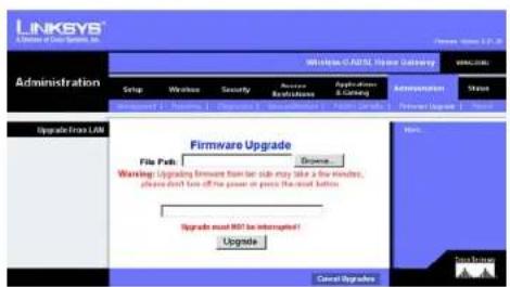
text_image
LINKSYS A Division of Data Systems, Inc. Administration Setup Wireless Security Accessories Installation Application (S)... Administration Status Upgrade From LAN Firmware Upgrade File Path: Browse Warning: Upgrading Amount from the side stay take a few minutes, please don't fix off the power or press the usual button Upgrade most NOT be interrupted! Upgrade Cancel Upgrades OK Cancel UpgradeFigure D-1: Firmware Upgrade
Wireless-G ADSL Home Gateway

802.11b - A wireless networking standard that specifies a maximum data transfer rate of 11Mbps and an operating frequency of 2.4GHz.
802.11g - A wireless networking standard that specifies a maximum data transfer rate of 54Mbps, an operating frequency of 2.4GHz, and backward compatibility with 802.11b devices.
Access Point - A device that allows wireless-equipped computers and other devices to communicate with a wired network. Also used to expand the range of a wireless network.
Adapter - A device that adds network functionality to your PC.
Ad-hoc - A group of wireless devices communicating directly with each other (peer-to-peer) without the use of an access point.
AES (Advanced Encryption Standard) - A security method that uses symmetric 128-bit block data encryption.
Backbone - The part of a network that connects most of the systems and networks together, and handles the most data.
Bandwidth - The transmission capacity of a given device or network.
Beacon Interval - Data transmitted on your wireless network that keeps the network synchronized.
Bit - A binary digit.
Boot - To start a device and cause it to start executing instructions.
Bridge - A device that connects different networks.
Broadband - An always-on, fast Internet connection.
Browser - An application program that provides a way to look at and interact with all the information on the World Wide Web.
Buffer - A shared or assigned memory area that is used to support and coordinate different computing and networking activities so one isn't held up by the other.
Byte - A unit of data that is usually eight bits long
Wireless-G ADSL Home Gateway
Cable Modem - A device that connects a computer to the cable television network, which in turn connects to the Internet.
CSMA/CA (Carrier Sense Multiple Access/Collision Avoidance) - A method of data transfer that is used to prevent data collisions.
CTS (Clear To Send) - A signal sent by a wireless device, signifying that it is ready to receive data.
Daisy Chain - A method used to connect devices in a series, one after the other.
Database - A collection of data that is organized so that its contents can easily be accessed, managed, and updated.
DDNS (Dynamic Domain Name System) - Allows the hosting of a website, FTP server, or e-mail server with a fixed domain name (e.g., www.xyz.com) and a dynamic IP address.
Default Gateway - A device that forwards Internet traffic from your local area network.
DHCP (Dynamic Host Configuration Protocol) - A networking protocol that allows administrators to assign temporary IP addresses to network computers by "leasing" an IP address to a user for a limited amount of time, instead of assigning permanent IP addresses.
DMZ (Demilitarized Zone) - Removes the Router's firewall protection from one PC, allowing it to be "seen" from the Internet.
DNS (Domain Name Server) - The IP address of your ISP's server, which translates the names of websites into IP addresses.
Domain - A specific name for a network of computers.
Download - To receive a file transmitted over a network.
DSL (Digital Subscriber Line) - An always-on broadband connection over traditional phone lines.
DSSS (Direct-Sequence Spread-Spectrum) - Frequency transmission with a redundant bit pattern resulting in a lower probability of information being lost in transit.
DTIM (Delivery Traffic Indication Message) - A message included in data packets that can increase wireless efficiency.
Dynamic IP Address - A temporary IP address assigned by a DHCP server.
Wireless-G ADSL Home Gateway
EAP (Extensible Authentication Protocol) - A general authentication protocol used to control network access. Many specific authentication methods work within this framework.
EAP-PEAP (Extensible Authentication Protocol-Protected Extensible Authentication Protocol) - A mutual authentication method that uses a combination of digital certificates and another system, such as passwords.
EAP-TLS (Extensible Authentication Protocol-Transport Layer Security) - A mutual authentication method that uses digital certificates.
Encryption - Encoding data transmitted in a network.
Ethernet - A networking protocol that specifies how data is placed on and retrieved from a common transmission medium.
Finger - A program that tells you the name associated with an e-mail address.
Firewall - A set of related programs located at a network gateway server that protects the resources of a network from users from other networks.
Firmware - The programming code that runs a networking device.
Fragmentation -Breaking a packet into smaller units when transmitting over a network medium that cannot support the original size of the packet.
FTP (File Transfer Protocol) - A protocol used to transfer files over a TCP/IP network.
Full Duplex - The ability of a networking device to receive and transmit data simultaneously.
Gateway - A device that interconnects networks with different, incompatible communications protocols.
Half Duplex - Data transmission that can occur in two directions over a single line, but only one direction at a time.
Hardware - The physical aspect of computers, telecommunications, and other information technology devices.
HTTP (HyperText Transport Protocol) - The communications protocol used to connect to servers on the World Wide Web.
Infrastructure - A wireless network that is bridged to a wired network via an access point.
IP (Internet Protocol) - A protocol used to send data over a network.
IP Address - The address used to identify a computer or device on a network.
Appendix E: Glossary
Wireless-G ADSL Home Gateway
IPCONFIG - A Windows 2000 and XP utility that displays the IP address for a particular networking device.
IPSec (Internet Protocol Security) - A VPN protocol used to implement secure exchange of packets at the IP layer.
ISM band - Radio bandwidth utilized in wireless transmissions.
ISP (Internet Service Provider) - A company that provides access to the Internet.
LAN - The computers and networking products that make up your local network.
LEAP (Lightweight Extensible Authentication Protocol) - A mutual authentication method that uses a username and password system.
MAC (Media Access Control) Address - The unique address that a manufacturer assigns to each networking device.
Mbps (MegaBits Per Second) - One million bits per second; a unit of measurement for data transmission.
mIRC - An Internet Relay Chat program that runs under Windows.
Multicasting - Sending data to a group of destinations at once.
NAT (Network Address Translation) - NAT technology translates IP addresses of a local area network to a different IP address for the Internet.
Network - A series of computers or devices connected for the purpose of data sharing, storage, and/or transmission between users.
NNTP (Network News Transfer Protocol) - The protocol used to connect to Usenet groups on the Internet.
Node - A network junction or connection point, typically a computer or work station.
OFDM (Orthogonal Frequency Division Multiplexing) - Frequency transmission that separates the data stream into a number of lower-speed data streams, which are then transmitted in parallel to prevent information from being lost in transit.
Packet - A unit of data sent over a network.
Passphrase - Used much like a password, a passphrase simplifies the WEP encryption process by automatically generating the WEP encryption keys for Linksys products.
PEAP (Protected Extensible Authentication Protocol) - A mutual authentication method that uses a combination of digital certificates and another system, such as passwords.
Appendix E: Glossary
Wireless-G ADSL Home Gateway
Ping (Packet INternet Groper) - An Internet utility used to determine whether a particular IP address is online.
POP3 (Post Office Protocol 3) - A standard mail server commonly used on the Internet.
Port - The connection point on a computer or networking device used for plugging in cables or adapters.
Power over Ethernet (PoE) - A technology enabling an Ethernet network cable to deliver both data and power.
PPPoE (Point to Point Protocol over Ethernet) - A type of broadband connection that provides authentication (username and password) in addition to data transport.
PPTP (Point-to-Point Tunneling Protocol) - A VPN protocol that allows the Point to Point Protocol (PPP) to be tunneled through an IP network. This protocol is also used as a type of broadband connection in Europe.
Preamble - Part of the wireless signal that synchronizes network traffic.
RADIUS (Remote Authentication Dial-In User Service) - A protocol that uses an authentication server to control network access.
RJ-45 (Registered Jack-45) - An Ethernet connector that holds up to eight wires.
Roaming - The ability to take a wireless device from one access point's range to another without losing the connection.
Router - A networking device that connects multiple networks together.
RTS (Request To Send) - A networking method of coordinating large packets through the RTS Threshold setting.
Server - Any computer whose function in a network is to provide user access to files, printing, communications, and other services.
SMTP (Simple Mail Transfer Protocol) - The standard e-mail protocol on the Internet.
SNMP (Simple Network Management Protocol) - A widely used network monitoring and control protocol.
Software - Instructions for the computer. A series of instructions that performs a particular task is called a "program".
SOHO (Small Office/Home Office) - Market segment of professionals who work at home or in small offices.
SPI (Stateful Packet Inspection) Firewall - A technology that inspects incoming packets of information before allowing them to enter the network.
Wireless-G ADSL Home Gateway
Spread Spectrum - Wideband radio frequency technique used for more reliable and secure data transmission.
SSID (Service Set Identifier) - Your wireless network's name.
Static IP Address - A fixed address assigned to a computer or device that is connected to a network.
Static Routing - Forwarding data in a network via a fixed path.
Subnet Mask - An address code that determines the size of the network.
Switch - 1. A data switch that connects computing devices to host computers, allowing a large number of devices to share a limited number of ports. 2. A device for making, breaking, or changing the connections in an electrical circuit.
TCP (Transmission Control Protocol) - A network protocol for transmitting data that requires acknowledgement from the recipient of data sent.
TCP/IP (Transmission Control Protocol/Internet Protocol) - A set of instructions PCs use to communicate over a network.
Telnet - A user command and TCP/IP protocol used for accessing remote PCs.
TFTP (Trivial File Transfer Protocol) - A version of the TCP/IP FTP protocol that has no directory or password capability.
Throughput - The amount of data moved successfully from one node to another in a given time period.
TKIP (Temporal Key Integrity Protocol) - a wireless encryption protocol that provides dynamic encryption keys for each packet transmitted.
Topology - The physical layout of a network.
TX Rate - Transmission Rate.
UDP (User Datagram Protocol) - A network protocol for transmitting data that does not require acknowledgement from the recipient of the data that is sent.
Upgrade - To replace existing software or firmware with a newer version.
Upload - To transmit a file over a network.
URL (Uniform Resource Locator) - The address of a file located on the Internet.
Wireless-G ADSL Home Gateway
VPN (Virtual Private Network) - A security measure to protect data as it leaves one network and goes to another over the Internet.
WAN (Wide Area Network)- The Internet.
WEP (Wired Equivalent Privacy) - A method of encrypting network data transmitted on a wireless network for greater security.
WINIPCFG - A Windows 98 and Me utility that displays the IP address for a particular networking device.
WLAN (Wireless Local Area Network) - A group of computers and associated devices that communicate with each other wirelessly.
WPA (Wi-Fi Protected Access) - a wireless security protocol using TKIP (Temporal Key Integrity Protocol) encryption, which can be used in conjunction with a RADIUS server.
Wireless-G ADSL Home Gateway

natural_image
Collection of black geometric symbols on white background, no text or labels presentCompliance Information for 2.4-GHz Wireless Products Relevant to the EU and Other Countries Following the EU Directive 1999/5/EC (R&TTE Directive)
Declaration of Conformity with Regard to the EU Directive 1995/5/EC (R&TTE Directive)
NOTE: For all products, the Declaration of Conformity is available through one or more of these options:
- A pdf file is included on the product's CD.
• A print copy is included with the product. - A pdf file is available on the product's webpage. Visit www.linksys.com/international and select your country or region. Then select your product.
If you need any other technical documentation, see the "Technical Documents on www.linksys.com/international" section, as shown later in this appendix.
The following standards were applied during the assessment of the product against the requirements of the Directive 1999/5/EC:
• Radio: EN 300 328
• EMC: EN 301 489-1, EN 301 489-17
• Safety: EN 60950
CE Marking
For the Linksys Wireless-B and Wireless-G products, the following CE mark, notified body number (where applicable), and class 2 identifier are added to the equipment.

Check the CE label on the product to find out which notified body was involved during the assessment.
| Česky [Czech]: | Toto zaízení je v souladu se základními požadavky a ostatními odpovidajícimi ustanoveními Směmice 1999/5/EC. |
| Dansk [Danish]: | Dette udstyr er i overensstemmelse med de væsentlige krav og andre relevante bestemmelser i Direktiv 1999/5/EF. |
| Deutsch [German]: | Dieses Gerät entspricht den grundlegenden Anforderungen und én weiteren entsprechenden Vorgaben der Richtlinie 1999/5/EU. |
| Eesti [Estonian]: | See szade vastab direktivi 1999/5/EU olulistele nõutele ja teistele asjakohastele sättetele. |
| English: | This equipment is in compliance with the essential requirements and other relevant provisions of Directive 1999/5/EC. |
| Español [Spanish]: | Este equipo cumple con los requisitos esenciales asi como con otras disposiciones de la Directiva 1999/5/CE. |
| Ελληνική [Greek]: | Autóç o εξοπλεμός είναι σε σομμόρφωση με της ουπόδεις απαιτήσεις και άλλες σχετικές διατάξιας της Οδηγιας 1999/5/EC. |
| Français [French]: | Cet appareil est conforme aux exigences essentielles et aux autres dispositions pertinentes de la Directive 1999/5/EC. |
| Íslenska [Icelandic]: | Ietta tæki er samkvæmt grunnkröfum og ðrum viðeigandi ákvaðum Tilskípunar 1999/5/EC. |
| Italiano [Italian]: | Questo apparato è conforme ai requisiti essenziali ed agli altri principi sanciti dalla Direttiva 1999/5/CE. |
| Latviski [Latvias]: | Št iekárta atbilst Direktīvas 1999/5/EK bütiskajám prasibám un citiem ar to saistitajiem noteikumiem. |
| Lietuviq [Lithuanian]: | Śis írenginys tenkina 1999/5/EB Direktyvos esminius reikalavimus ir kitas sios direktyvos nuostaras. |
| Nederlands [Dutch]: | Dit apparaat voldoet aan de essentiele eixen en andere van toepassing zijnde bepalingen van de Richtlijn 1999/5/EC. |
| Malti [Maltese]: | Dan l-apparat huwa konformi mal-ħtigiet essenzjali u l-provedimenti l-obra rilevanti tad-Direttiva 1999/5/EC. |
| Margyar [Hungacian]: | Ez a készülék teljesíti az alapvető követelményeket és más 1999/5/EK irányelvben meghatározott vonatkozó rendelkezéseket. |
Wireless-G ADSL Home Gateway
National Restrictions
This product may be used in all EU countries (and other countries following the EU directive 1999/5/EC) without any limitation except for the countries mentioned below:
The Belgian Institute for Postal Services and Telecommunications (BIPT) must be notified of any outdoor wireless link having a range exceeding 300 meters. Please check http://www.bipt.be for more details.
| Norsk[Norwegian]: | Dette utstyret er i samsvar med de grunnleggende krav og andre relevante bestemmelser i EU-direktiv 1999/5/EF. |
| Polski[Polish]: | Urządzenie jest zgodne z ogólnymi wymaganiami oraz szczególnymi warunkami określonymi Dyrektywą UE: 1999/5/EC. |
| Português[Portuguese]: | Este equipamento está em conformidade com os requisitos essenciais e outras provisões relevantes da Direktiva 1999/5/EC. |
| Slovensko[Slovenian]: | Ta naprava je skladna z bistvenimi zahtevami in ostalimi relevantnimi pogoji Direktive 1999/5/EC. |
| Slovensky[Slovak]: | Toto zariadenie je v zhode so základnými požiadavkami a irými prislušnými nariadeniami direktiv: 1999/5/EC. |
| Suomi[Finnish]: | Tamá laite tayttaa direktiivin 1999/5/EY olennaiset vaatimukset ja on siina asetettujen muiden laitetta koskevien määräysten mukainen. |
| Svenska[Swedish]: | Denna utrustning lär i överensstämmelse med de väsentliga kraven och andra relevanta bestämmelser i Direktiv 1999/5/EC. |
Wireless-G ADSL Home Gateway
France
In case the product is used outdoors, the output power is restricted in some parts of the band. See Table 1 or check http://www.art-telecom.fr/ for more details.
Table 1: Applicable Power Levels in France
| Location Frequency Range (MHz) Power (EIRP) | ||
| Indoor (No restrictions) 2400-2483.5 100 mW (20 dBm) | ||
| Outdoor 2400-2454 | 2454-2483.5 | 100 mW (20 dBm)10 mW (10 dBm) |
Italy
This product meets the National Radio Interface and the requirements specified in the National Frequency Allocation Table for Italy. Unless operating within the boundaries of the owner's property, the use of this 2.4 GHz Wireless LAN product requires a 'general authorization'. Please check with http://www.comunicazioni.it/it/ for more details.
This product is designed for indoor usage only. Outdoor usage is not recommended. Any modification or alteration to the product shall void the warranty (see the Warranty Information appendix in this User Guide).
This product is designed for use with the standard, integral or dedicated (external) antenna(s) that is/are shipped together with the equipment. However, some applications may require the antenna(s) to be separated from the product and installed remotely from the device by using extension cables. For these applications, Linksys offers an R-SMA extension cable (AC9SMA) and an R-TNC extension cable (AC9TNC). Both of these cables are 9 meters long and have a cable loss (attenuation) of 5 dB. To compensate for the attenuation, Linksys also offers higher gain antennas, the HGA7S (with R-SMA connector) and HGA7T (with R-TNC connector). These antennas have a gain of 7 dBi and may only be used with either the R-SMA or R-TNC extension cable.
Combinations of extension cables and antennas resulting in a radiated power level exceeding 100 mW EIRP are illegal.
Wireless-G ADSL Home Gateway
Power Output of Your Device
To comply with your country's regulations, you may have to change the power output of your wireless device. Proceed to the appropriate section for your device.
Note: The power output setting may not be available on all wireless products. For more information, refer to the documentation on your product's CD or http://www.linksys.com/international.
Wireless Adapters
Wireless adapters have the power output set to 100% by default. Maximum power output on each adapter does not exceed 20 dBm (100 mW); it is generally 18 dBm (64 mW) or below. If you need to alter your wireless adapter's power output, follow the appropriate instructions for your computer's Windows operating system:
Windows XP
- Double-click the Wireless icon in your desktop's system tray.
- Open the Wireless Network Connection window.
- Click the Properties button.
- Select the General tab, and click the Configure button.
- In the Properties window, click the Advanced tab.
- Select Power Output.
- From the pull-down menu on the right, select the wireless adapter's power output percentage.
Windows 2000
- Open the Control Panel.
- Double-click Network and Dial-Up Connections.
- Select your current wireless connection, and select Properties.
- From the Properties screen, click the Configure button.
- Click the Advanced tab, and select Power Output.
- From the pull-down menu on the right, select the wireless adapter's power setting.
If your computer is running Windows Millennium or 98, then refer to Windows Help for instructions on how to access the advanced settings of a network adapter.
Wireless Access Points, Routers, or Other Wireless Products
If you have a wireless access point, router or other wireless product, use its Web-based Utility to configure its power output setting (refer to the product's documentation for more information).
Wireless-G ADSL Home Gateway
Technical Documents on www.linksys.com/international
Follow these steps to access technical documents:
- Browse to http://www.linksys.com/international.
- Click the region in which you reside.
- Click the name of the country in which you reside.
- Click Products.
- Click the appropriate product category.
- Select a product.
- Click the type of documentation you want. The document will automatically open in PDF format.
Note: If you have questions regarding the compliance of these products or you cannot find the information you need, please contact your local sales office or visit http://www.linksys.com/international for more details.
Wireless-G ADSL Home Gateway

natural_image
Collection of black and white geometric symbols including stars, circles, and squares (no text or labels)Linksys warrants to You that, for a period of three years (the "Warranty Period"), your Linksys Product will be substantially free of defects in materials and workmanship under normal use. Your exclusive remedy and Linksys' entire liability under this warranty will be for Linksys at its option to repair or replace the Product or refund Your purchase price less any rebates. This limited warranty extends only to the original purchaser.
If the Product proves defective during the Warranty Period call Linksys Technical Support in order to obtain a Return Authorization Number, if applicable. BE SURE TO HAVE YOUR PROOF OF PURCHASE ON HAND WHEN CALLING. If You are requested to return the Product, mark the Return Authorization Number clearly on the outside of the package and include a copy of your original proof of purchase. RETURN REQUESTS CANNOT BE PROCESSED WITHOUT PROOF OF PURCHASE. You are responsible for shipping defective Products to Linksys. Linksys pays for UPS Ground shipping from Linksys back to You only. Customers located outside of the United States of America and Canada are responsible for all shipping and handling charges.
ALL IMPLIED WARRANTIES AND CONDITIONS OF MERCHANTABILITY OR FITNESS FOR A PARTICULAR PURPOSE ARE LIMITED TO THE DURATION OF THE WARRANTY PERIOD. ALL OTHER EXPRESS OR IMPLIED CONDITIONS, REPRESENTATIONS AND WARRANTIES, INCLUDING ANY IMPLIED WARRANTY OF NON-INFRINGEMENT, ARE DISCLAIMED. Some jurisdictions do not allow limitations on how long an implied warranty lasts, so the above limitation may not apply to You. This warranty gives You specific legal rights, and You may also have other rights which vary by jurisdiction.
This warranty does not apply if the Product (a) has been altered, except by Linksys, (b) has not been installed, operated, repaired, or maintained in accordance with instructions supplied by Linksys, or (c) has been subjected to abnormal physical or electrical stress, misuse, negligence, or accident. In addition, due to the continual development of new techniques for intruding upon and attacking networks, Linksys does not warrant that the Product will be free of vulnerability to intrusion or attack.
TO THE EXTENT NOT PROHIBITED BY LAW, IN NO EVENT WILL LINKSYS BE LIABLE FOR ANY LOST DATA, REVENUE OR PROFIT, OR FOR SPECIAL, INDIRECT, CONSEQUENTIAL, INCIDENTAL OR PUNITIVE DAMAGES, REGARDLESS OF THE THEORY OF LIABILITY (INCLUDING NEGLIGENCE), ARISING OUT OF OR RELATED TO THE USE OF OR INABILITY TO USE THE PRODUCT (INCLUDING ANY SOFTWARE), EVEN IF LINKSYS HAS BEEN ADVISED OF THE POSSIBILITY OF SUCH DAMAGES. IN NO EVENT WILL LINKSYS' LIABILITY EXCEED THE AMOUNT PAID BY YOU FOR THE PRODUCT. The foregoing limitations will apply even if any warranty or remedy provided under this Agreement fails of its essential purpose. Some jurisdictions do not allow the exclusion or limitation of incidental or consequential damages, so the above limitation or exclusion may not apply to You.
This Warranty is valid and may be processed only in the country of purchase.
Please direct all inquiries to: Linksys, P.O. Box 18558, Irvine, CA 92623.
Wireless-G ADSL Home Gateway

Model Number WAG354G
Standards IEEE 802.11g, IEEE 802.11b, IEEE 802.3, IEEE 802.3u, G.992.1 (G.dmt), G.992.2 (G.lite), G.992.3, G.992.5, T1.413i2
Ports Power, ADSL, Ethernet (1-4)
Button One Reset Button
Cabling Type CAT 5 UTP
LEDs Power, Wireless, Ethernet (1-4), DSL, Internet
Transmit Power 18 dBm
Channels 13 (most of Europe)
UPnP able/cert Able
Security Features Password protected configuration for web access
PAP and CHAP authentication
Denial of Service (DoS) Prevention
URL filtering, and keyword, Java, ActiveX, Proxy, Cookie blocking
ToD filter (Blocks Access by Time)
VPN Passthrough for IPSec, PPTP, and L2TP Protocols
128, 64 bits WEP with Passphrase WEP key generation
SSID Broadcast Disable
Access restriction by MAC and IP addresses
WEP Key Bits 64, 128
Wireless-G ADSL Home Gateway
Dimensions 140 mm x 140 mm x 27 mm (5,51" x 5,51" x 1,06")
Unit Weight 0,3 kg (0,6 lb.)
Power 12VDC 1A
Certifications CE
Operating Temp. 0°\~40°C (32°\~104°F)
Storage Temp. -20°\~70°C (-4°\~158°F)
Operating Humidity 10\~85% Non-Condensing
Storage Humidity 5\~90% Non-Condensing
Wireless-G ADSL Home Gateway

Need to contact Linksys?
Visit us online for information on the latest products and updates to your existing products at:
http://www.linksys.com/international
If you experience problems with any Linksys product, you can e-mail us at:
| In Europe E-mail Address | |
| Austria support.at@linksys.com | |
| Belgium support.be@linksys.com | |
| Denmark support.dk@linksys.com | |
| France support.fr@linksys.com | |
| Germany support.de@linksys.com | |
| Italy support.it@linksys.com | |
| Netherlands support.nl@linksys.com | |
| Norway support.no@linksys.com | |
| Portugal support.pt@linksys.com | |
| Spain support.es@linksys.com | |
| Sweden support.se@linksys.com | |
| Switzerland support.ch@linksys.com | |
| United Kingdom & Ireland support.uk@linksys.com |
| Outside of Europe | E-mail Address |
| Latin America | support.la@linksys.com |
| U.S. and Canada | support@linksys.com |
Appendix I: Contact Information
LINKSYS®
A Division of Cisco Systems, Inc.

natural_image
White wireless router device with dotted pattern and blue logo, no visible text or symbols on body2,4 GHz 802.11g
Wireless-G
ADSL-Home-Gateway
Benutzerhandbuch
WIRELESS
Cisco SYSTEMS

Wireless-G ADSL-Home-Gateway
Begriff: Definition.
Wireless-G ADSL-Home-Gateway
☆■✿◇▼▲◆□■✿✿◆■▲
Wireless-G ADSL-Home-Gateway
Wireless-G ADSL-Home-Gateway
[Non-Text]
Wireless-G ADSL-Home-Gateway
Wireless-G ADSL-Home-Gateway

Willkommen
Wireless-G ADSL-Home-Gateway
Wireless-G ADSL-Home-Gateway
Wireless-G ADSL-Home-Gateway
Wireless-G ADSL-Home-Gateway
Wireless-G ADSL-Home-Gateway

text_image
Image displaying a series of black-and-white symbols including stars, circles, and triangles with standard geometric markings.Wireless-G ADSL-Home-Gateway
Wireless-G ADSL-Home-Gateway
Untere Gehäusekante
natural_image
Front view of a white wireless router with a blue 'LINKSYS' logo and control panel (no readable text beyond branding)Wireless-G ADSL-Home-Gateway

text_image
Collection of symbolic and stylized icons including stars, squares, and triangles with standard text alignmentÜbersicht
Wireless-G ADSL-Home-Gateway
natural_image
Front view of a network switch with Ethernet ports and a USB port (no visible text or symbols)natural_image
Close-up of a network switch with Ethernet port and power interface (no text or symbols visible)natural_image
Front view of a network switch with Ethernet ports and a USB port (no visible text or symbols)Wireless-G ADSL-Home-Gateway
natural_image
Front view of a network switch with four Ethernet ports and a power button (no visible text or symbols)natural_image
Close-up of a network switch with four Ethernet ports and a USB cable (no text or symbols visible)Wireless-G ADSL-Home-Gateway
☆□※※○×+ ☆□■※※◆□※□※■※※▲★□※※▲▲☆☆※☆★□○※☆
Übersicht
Wireless-G ADSL-Home-Gateway
Wireless-G ADSL-Home-Gateway
Status
text_image
LINKSYS Setup Setup Status Status Import Export Access Accession Administration Status Initial Settings External Connection Type IC Settings Displacement: AFC HD3 Budgeted Multifunction: 1.5V 1.5V Grid Type: IUSB For Rate: 0.0000 For Rate: 0.0000 Automatic: 1.0V 1.0V Value Output: 0 V/ Charge (2/25) 0 V/ Charge (10-6990) P Settings * Update as P Address Automatically * Update following P Address: Internal P Address: 1.5V 1.5V Subtotal Method: 1.5V 1.5V Database: 1.5V 1.5V Primary AND 1.5V 1.5V Secondary AND 1.5V 1.5V Optional Settings <|vision_start|> User by name B/C Print Time: Print Address: Auto MUL: 1.5V Size: 1.5V Network Settings Model P Local P Address: 1.5V 1.5V 1.5V Subtotal Method: 1.5V 1.5V 1.5V Network Address: P Address: 1.5V 1.5V 1.5V DCI7 Path Server: 1.5V 1.5V 1.5V Starting P Address: 1.5V 1.5V 1.5V External Destination: 1.5V 1.5V 1.5V DCI7 User: 1.5V 1.5V 1.5V Client User Type: 1.5V 1.5V 1.5V Data: DCL 1: 0 0 0 0 Data: DCL 2: 0 0 0 0 Data: DCL 3: 0 0 0 0 WBC: 0 0 0 0 0 Time Setting: Time Zone: DCI7-88-88 Traffic Time (USAS Console) Time Interval: 1.5V 1.5V IP automatically adjust user to weight using chargesWireless-G ADSL-Home-Gateway
text_image
Internet Setup Internet Connection Type VC Settings Incorporation: RFC 1453 Bridged ▼ Multiparings ▲ LLC ▼ VC Gas Type: UBR For Rate: 0 dpi Size Rate: 0 dpi Autodetect: ○ Enable ▲ Enable Virtual Circuit: 0 VIT (Range 0-255) 35 VQ (Range 32-65535) IP Settings ○ Obtain an IP Address Automatically ○ Use the following IP Address: Internet P Address: □ □ □ □ Subnet Mask: □ □ □ □ Gateway: □ □ □ □ Primary DNS: □ □ □ □ Secondary DNS: □ □ □ □text_image
Internet Setup Internet Connection Type VC Settings Inceapsulation: RFC 1483 Bridged * Multiplicating: LLC VC Qoq Type: UBR For Rate: 000 Scr Rate: 000 Autodetect: Enable Enable Virtual Circuit: 0 VR (Range 0-255) 35 VD (Range 30-65535) IP Settings Obtain an IP Address Automatically Use the following IP Address: Internet IP Address: 0 3 0 0 Submit Waste: 0 3 0 0 Delivery: 0 3 0 0 Primary DMS: 0 3 0 0 Secondary DMS: 0 3 0 0Wireless-G ADSL-Home-Gateway
text_image
Internet Setup Internet Connection Type VC Settings Encapsulation: RPC1483 Rejected Multiplexing: LLC VC Gas Type: UBR Por Rate: rpm Cor Rate: rpm Autodetect: Enable Disable Virtual Circuit: 0 VR (Range 0-255) VCS VCI (Range 32-65505) IP Settings Internet IP Address: 0 1 2 3 4 Submit Waste: 0 1 2 3 4 Gateway: 0 1 2 3 4 Primary DNS: 0 1 2 3 4 Secondary DNS: 0 1 2 3 4text_image
Internet Setup Internet Connection Type VC Settings Encapsulation: RFCC 2516 PPPoE Multiplexing: a LLC vc Gene Type: UBR Pcr Rate: cps Scr Rate: cps Autoselect: Enable if Enable Virtual Circuit: 0 VPI (Range 0-265) 35 VCI (Range 20-8503) PPPoE Settings Service Name: User Name: Password: if Connect on Demand: Max life time 20 Min. Keep Alive Redial period 20 Sec.Abbildung 5-6: RFC 2516 PPPoE
Wireless-G ADSL-Home-Gateway
RFC 2364 PPPoA
text_image
Internet Setup Internet Connection Type VC Settings Incorporation: Bridge Mode Only Multiplexing: LLC NC Opt Type: LER Por Rate: 0 cps Sor Rate: 0 cps Autodetect: Enable Enable Virtual Circuit: 0 VCI (Range 0-200) 35 VCI (Range 32-69538) Optional Settings (required by some IRPs) Host Name: Domain Name: MTU: Auto Size: 1.172Wireless-G ADSL-Home-Gateway
Netzwerkeinrichtung
text_image
Optional Settings (required by some ISPs) Host Name: Domain Name: HTU: Auto Size: 1192 Network Setup Router IP Local IP Address: 192, 160, 1, 1 Submit Mask: 255, 255, 255, 0 Network Address Server Settings (DHCP) Local DHCP Server: Enable Enable DHCP Relay DHCP Relay Server: 0, 0, 0, 0 Starting IP Address: 150,988.1, 0.4 Minimum Number of DHCP Users: 191 Client Lease Time: 0 minutes (6 means one day) Static DNS 1: 0, 0, 0, 0 Static DNS 2: 0, 0, 0, 0 Static DNS 3: 0, 0, 0, 0 WING: 0, 0, 0, 0 Time Setting Time Zone: (GMT-08:00 Pacific Time (USA & Canada)) Time Interval: 36.00 seconds Automatically adjust clock for devalnt swing changesWireless-G ADSL-Home-Gateway
text_image
LINKSYS A software of DOS Systems, Inc. Setup Wireless C:DNS Server Gateway VOC:DNS Setup Wireless Security Access Administration Applications & Services Administration Status User Setup DOS Advanced Trading DNS Service: CyE-DRG.org User Name: Password: Mail Name: Internet P: Address: Status: Save Settings Cancel Changes Store Bus Data SourceAbbildung 5-10: DynDNS.org
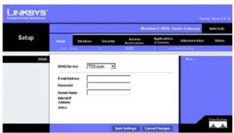
text_image
LINKSYS A:\Users\Data\Systems Setup Windows C: DOS Name Gateway Setup Wireless Security Access Restrictions Applications & Currency Administration Status Start Settings Cancel Changes BDFS Service 120 com Email Address Password Domain Name Internet P Address Status Next Settings Cancel Changes Send Settings Cancel ChangesWireless-G ADSL-Home-Gateway
text_image
LINKSYS A Division of Data Systems, Inc. Setup Wireless & ARSL Network Scaling Status OK Cancel Set Up Send Settings Security Access Application & Connection Administration Status Automatic Routing Adversal Routing Operating Mode NA: Enabled Disabled RIP Enabled Disabled Send Default Route Enable Disabled Interface Transient RIP Version: ASP1 Receiving RIP Version: ASP1 MultiBand or Broadcast: MultiBand Static Routing Select set number: 1 Delete This Entry: Destination IP Address: 0 0 0 0 Submit Work: 0 0 0 0 Outperform: 0 0 0 0 Map Check: 1 Show Routing Tabo Save Settings Cancel Changes Next Save SettingsWireless-G ADSL-Home-Gateway
Wireless-G ADSL-Home-Gateway
text_image
LINKSYS A Network of Data Systems, Inc. Windows 0.40% Name Currency Wireless Wireless Network Mode: Mixed Wireless Network Name (SDD): Linksys Wireless Channel: -2.07946 Wireless SSD Broadcast: Enable Disable Save Settings Cancel Changes Back Data SummaryWireless-G ADSL-Home-Gateway
text_image
LINKSYS A Security Of Data Systems, Inc. Windows C:\ASP\Home Category WINSCH Wireless Seto Windows Security Access Networks Applications Setting Administration Main Wireless Security Security Note: WINS (Pre-Shared Key) WNS Shared Key Snap Over Retinal: Jack seconds Wireless Security Name Save Settings Cancel Changes Next UpdateWireless-G ADSL-Home-Gateway
text_image
LINKSYS A Version of Data Setset, Inc. Wireless G-ADSL Home Setting WANCOOL Setup Wireless Security Access Refreshless Applicable & Closing Administration Status Show: 100 MHz Show: 100 MHz Show Security Wireless Security Security Mode: MEP Outlook Transmit 1 2 3 4 MEP Duration: 14 bits 10 new digits Accession: Camera Key 1: Key 2: Key 3: Key 4: New Settings Cancel Changes Note Data Breaks AAbbildung 5-16: WEP
Wireless-G ADSL-Home-Gateway
Registerkarte „Wireless Access“ (Wireless-Zugriff)
text_image
LINKSYS A Series of Data Systems, Inc. Wireless LinkSYS C:\ADSL Home Database Settings Setup Wireless Security Access Resources Application & Comp Administration Status Wireless Network Access Allow All Install Access Present computers listed below from accessing the wireless network Payout only computers listed below to access the wireless network Edit MBC: Microsoft Access List Save Settings Direct Change Home Data Securitytext_image
MAC Address Filter List Enter MAC Address Format: xxxxxxxxxxxxx/xxx.xx.xx.xx MAC 01: MAC 11: MAC 02: MAC 12: MAC 03: MAC 13: MAC 04: MAC 14: MAC 05: MAC 15: MAC 06: MAC 16: MAC 07: MAC 17: MAC 08: MAC 18: MAC 09: MAC 19: MAC 10: MAC 20: Wireless Client MACList Save Settings Cancel ChangesWireless-G ADSL-Home-Gateway
Wireless-G ADSL-Home-Gateway
text_image
LINKSYS J Division of One System, Inc. Windows C: A850, Windows Security Welcome: Security Setup Windows Security Access Access Systems Applications ( & Default) Administration Status VRS PortThrough VRS PortThrough Enable Disable VRS PortThrough Enable Disable VRS PortThrough Enable Disable USB PortThrough Enable Disable Forward Protection Enable Disable Additional filters File Proxy Filter Cookies File drive Applics Filter subnet Show YAM Response Show Analytical Internal Properties View Links Save Settings Cancel ChangesWireless-G ADSL-Home-Gateway
Zusätzliche Filter
text_image
System Log Firewall Log ▼ Clear pageRefresh Clear pageRefresh Previous Page Next PageWireless-G ADSL-Home-Gateway
text_image
LINKSYS Access Restrictions Welcome C:\APCEL\Apache\Comstock\WRCMS\ TITLE ACCESS Normal Access Policy: 10 Delete Summary Status: Stable Stable Enter Policy Name: Kc: Edit List of PCs Deny Allow Internet access during selected days and hours. Begin Everyday: Sun Mon Tue Hold Tue Fri Set Times 34 Hours: From To From Website Blocking by MS Address Website Blocking by Reynond Blocked Services None - Name - AddEdit Service Save Settings Cancel Changes Name Save Settings Cancel ChangesWireless-G ADSL-Home-Gateway
text_image
List of PCs Enter MAC Address of the PCs in this temat: xxxxxxxxxxxxxxx MAC 01: 00:03:00:00:00:00 MAC 02: 00:03:00:00:00:00 MAC 03: 00:03:00:00:00:00 MAC 04: 00:03:00:00:00:00 MAC 05: 00:03:00:00:00:00 MAC 06: 00:03:00:00:00:00 MAC 07: 00:03:00:00:00:00 MAC 08: 00:03:00:00:00:00 Enter the IP Address of the PCs IP 01: 192.168.1 [ ] IP 04: 192.168.1 [ ] IP 02: 192.168.1 [ ] IP 05: 192.168.1 [ ] IP 03: 192.168.1 [ ] IP 06: 192.168.1 [ ] Enter the IP Range of the PCs IP Range 01: 192.168.1 [ ] - [ ] IP Range 02: 192.168.1 [ ] - [ ] Save Settings Cancel ChangesWireless-G ADSL-Home-Gateway
Wireless-G ADSL-Home-Gateway
text_image
LINKSYS A GAMES OF LIME SYSTEMS, INC. Applications & Gaming Windows & ANSI Home Calendar WINCHES: Setup Wireless Security Access Instructions Application Security Administration Status Port Range Forwarding Port Range Application Start End Protocol P Address Enable 10 to 9 Both 102.1681.1 10 to 9 Both 102.1681.1 10 to 9 Both 102.1681.1 10 to 9 Both 102.1681.1 10 to 9 Both 102.1681.1 10 to 9 Both 102.1681.1 10 to 50 to 9 Both 102.1681.1 50 to 9 Both 102.1681.1 50 to 9 Both 102.1681.1 50 to 9 Save Settings Cancel ChangesWireless-G ADSL-Home-Gateway
Wireless-G ADSL-Home-Gateway
Registerkarte „DMZ“
text_image
LINKSYS® A Division of Cell System, Inc. Applications & Gaming Windows C / MDL Home Gateway WWCMC Setup Windows Cancel Access Applications Applications & Gaming Administration Status SaaS FdFtFtFtFtFtFtFtFtFtFtFtFtFtFtFtFtFtFtFtFtFtFtFtFtFtFtFtFtFtFtFtFtFtFtFtFtFtFtFtFtFtFtFtFtFtFtFtFtFtFtFm DML DNS Hs2 Hs2 C Enable C Enable DNS Host IP Address: 182.964.5 (valid range in 1.254) Win: Win InventoryAbbildung 5-30: DMZ
Wireless-G ADSL-Home-Gateway
Registerkarte „QoS“
QoS
text_image
LINKSYS A Software & Gaming System Applications &Gaming Windows C:\MOS\Material Category Setup Wireless Security Access Services Application & Administration Value Specialty: Test Design: 100% High priority Medium priority Low priority FTP C C C FTP C C C Subnet C C C SMTP C C C POP3 C C C Specific Port0 C C C Specific Port0 C C C Specific Port0 C C C SaaS Settings Cancel ChangesAbbildung 5-31: QoS
Wireless-G ADSL-Home-Gateway
Gateway Access (Gateway-Zugriff)
text_image
LINKSYS A Class or Day System, Inc. Windows C:\MSL\Home Gateway Administration Status: 1980000 Security Access Restrictions Applications & Clearing Administration Status Gateway Access Local Gateway Access Gateway Contact: 1 Gateway Timestamp: August Gateway Timestamp: **** Ro-order to confirm: **** Remote Gateway Access Remote Management: Enable Enable Management Port: **** Allowed F: Remote Upgrade: Enable Enable SNAP SNAP: Enable Enable Device Name: NAO354G Snap V/V2 Get Community: public Set Community: private Top Management: Top No: 172 164 1 132 SNAP SNAP: Enable Enable SNAP Print: Enable Enable Network: www.LIAN Transport Settings Cancel Changes OKWireless-G ADSL-Home-Gateway
SNMP
Wireless-G ADSL-Home-Gateway
text_image
LINKSYS C:\Users\Data Center Inc Administration Setup Wireless Security Access Instructions Applications & Settings Administration Settings Reporting Log Enable "Enable" LogInner IP Address: 952.168.5 100 Event Alerts Enabled "Enabled" Event of Service Thresholds: 20 events (20 - 100) SMTP Med Server: Event Address for Alert Logo: Return Email Address: View logo Save Settings Cancel Changes Back Forward Next UpdateWireless-G ADSL-Home-Gateway
Registerkarte „Diagnostics“ (Diagnose)
Ping-Test
Ping-Test-Parameter
text_image
LINKSYS® A Division of Cloud Systems, Inc. Administration Ping Test Ping Test Parameters Ping Target: 0 0 0 0 Ping Size: 62 Bytes Number of Plogs: 1 (Range 1-100) Ping Interval: 1503 MioSvcs Ping Amount: $500 MioSvcs Ping Result: Plot Sort All PktBased Avg Std Save Settings Cancel Change Next Save NumbersWireless-G ADSL-Home-Gateway
text_image
LINKSYS A Division of Data Systems, Inc. Administration Microsoft SQL Server Administration WAL-2016 Setup Windows Security Accounts Availability Platform Administration Value Management 1 Maintenance 2 Maintenance & Coding Factory Default Restore Factory Default: Yes No Save Settings Cancel Changes Next Gains Servicestext_image
LINKSYS® WINKSU.O. 2019 Home Gateway Administration Setup Wireless Security Access Networks Applications Application Administration Status Package 1 - Security 1 - Security 2 - Security 3 - Main Street 4 - Firmware Upgrade 5 - Real Upgrade From User Firmware Upgrade File Park Service Walking: Upgrading Firmware from last side may call a few minutes, please don't turn off the power in press the next button. Upgrade more than 80% to interrupt! Upgrade Cancel/AppendixWireless-G ADSL-Home-Gateway
text_image
LINKSYS A Software in this system is Windows 6 ADS Server Gateway WBS3245 Administration Setup Services Security Access Accessories Applications & Controls Administrative Status Amounts: Settings: Parameters: Settings Application Services and Web Reboot Reboot Mode: Hard Soft Save Settings Cancel Changes Free EntryWireless-G ADSL-Home-Gateway
text_image
LINKSYS J Server & CNT System, Inc. Status Windows C:\ADSL\Name Category: MACHS Setup Wireless Security Access Network Address Applications A Network Administration Status Internet Information In millions/1000s: 8.41.06; Fax 15-6995 MAC Address: 99.80.64-AA-65-88 Current Time: Not Available Internet Connections Login Type: EMCP HostLine: Up P Address: 10.3.078 Submit Mode: 256.205.255.8 Default Delivery: 95.1.01 DNS 1: 206.11.28.52 DNS 2: 206.11.28.52 DNS 3: 8.8.8.8 WNS: DHCP Database DHCP Review RefreshWireless-G ADSL-Home-Gateway
text_image
LINKSYS A Website of Data Systems, Inc. Status Windows C: ADSL User Gateway WINS/2016 Setup Windows Security Access Restrictions Applications & Settings Administration Name Local Network MAC Address: 90-80-66-AA-64.87 P Address: 192.58.1.1 Send Work: 253.26.254.8 DHCP Server: Enable Send P Address: 192.58.1.64 Send P Address: 192.58.1.254 DHCP Clients Table AND/RARP Table Networktext_image
DHCP Active IP Table DHCP Server IP Address: 192.168.1.1 Client Host Name IP Address MAC Address Expires Delete None None None None CloseWireless-G ADSL-Home-Gateway
text_image
LINKSYS A Series of Data Systems, Inc. Status Wireless C:\ADRS\Windows\Locking Status Wireless Version: SLSN MAC Address: "B########## Mode: Mixed SDD: Inags DHCP Server: Enable Channel: 0 Encryption Function: Statusled Wireless Clients Connected MACHNIC Status None... Return Data Privacy Send to: Send to: Send to: Send to:text_image
Networked Computers Refresh Computer Name IP Address MAC Address CloseWireless-G ADSL-Home-Gateway
text_image
LINKSYS A License or Cus Software Windows C: ADSL Power Gateway Status Setup Windows Security Active Applications Applications A Setting Administration OSL Status DSL Status RF DSL Modulation Mode F14F3 DSL Push Mode FAST Downstream Rate 9064.8bps Upstream Rate 9024.8bps Downstream Margin 53 db Upstream Margin 3 db Downstream Load Information: > Upstream Line Attenuation: | Downstream Transd Power: | Upstream Transd Power: | PVC Connection Exposulation 97C 140 (Shigged) Multilinking LLC Geo IRR For Rate # For Rate # Autoreset Mobile VR # VO 3S Driver Yes PVC Status Applied - OK RefreshWireless-G ADSL-Home-Gateway
\*
Wireless-G ADSL-Home-Gateway
Wireless-G ADSL-Home-Gateway
Wireless-G ADSL-Home-Gateway
Wireless-G ADSL-Home-Gateway
Wireless-G ADSL-Home-Gateway
Wireless-G ADSL-Home-Gateway
Wireless-G ADSL-Home-Gateway
Wireless-G ADSL-Home-Gateway
Wireless-G ADSL-Home-Gateway
Wireless-G ADSL-Home-Gateway
Wireless-G ADSL-Home-Gateway
Wireless-G ADSL-Home-Gateway
Wireless-G ADSL-Home-Gateway
Wireless-G ADSL-Home-Gateway
Wireless-G ADSL-Home-Gateway
Wireless-G ADSL-Home-Gateway
Wireless-G ADSL-Home-Gateway
\*■\*■\* + \*\*\*□\*\*▼ \*○ ★□\*▲☆\*VID \*□\*□□
Wireless-G ADSL-Home-Gateway
Wireless-G ADSL-Home-Gateway
Wireless-G ADSL-Home-Gateway
☆■※□※☆+○※□※□★☆☆☆☆□※▲※◆□※※□☆☆☆□※▲※※▲+▼※□□※▼△☆※□▼※□▲
Wireless-G ADSL-Home-Gateway
Wireless-G ADSL-Home-Gateway
[Non-Text]
text_image
LINKSYS A Division of Data Systems, Inc. Administration Setup Wireless Security Accessories Installation Application (S)... Administration Status Upgrade From LAN Firmware Upgrade File Path: Browse Warning: Upgrading Amount from the side stay take a few minutes, please don't fix off the power or press the usual button Upgrade most NOT be interrupted! Upgrade Cancel Upgrades OK Cancel UpgradeWireless-G ADSL-Home-Gateway
![LINKSYS WAG354G - [Non-Text] - 1](/content/2026/06/1238907/images/ae3e5aef88d1bebbd463faa7f687a9c064528fccbe12d5124ae4a226fa02f37e.jpg)
Wireless-G ADSL-Home-Gateway
Wireless-G ADSL-Home-Gateway
Wireless-G ADSL-Home-Gateway
Wireless-G ADSL-Home-Gateway
Wireless-G ADSL-Home-Gateway
Wireless-G ADSL-Home-Gateway
Wireless-G ADSL-Home-Gateway
Wireless-G ADSL-Home-Gateway

natural_image
Collection of black geometric symbols on white background, no text or labels presentFCC-Bestimmungen
Wireless-G ADSL-Home-Gateway
Wireless-G ADSL-Home-Gateway
| Norsk[Norwegian]: | Dette utstyret er i samsvar med de grunnleggende krav og andre relevante bestemmelser i EU-direktiv 1999/5/EF. |
| Polski[Polish]: | Urządzenie jest zgodne z ogólnymi wymaganiami oraz szczególnymi warunkami określonymi Dyrektywą UE: 1999/5/EC. |
| Portugües[Portuguese]: | Este equipamento está em conformidade com os requisitos essenciais e outras provisões relevantes da Directiva 1999/5/EC. |
| Slovensko[Slovenian]: | Ta naprava je skladaa z bistvenimi zahtevami in ostalini relevantnimi pogoji Direktive 1999/5/EC. |
| Slovensky[Slovak]: | Toto zariadenie je v zhode so základnými požiadavkami a inými príslušnými nariadeniami direktiv: 1999/5/EC. |
| Suomi[Finnish]: | Táml laite täyttälä direktiivin 1999/5/EY olemaiset vaatimukset ja on siină asctettujen muiden laitetta koskevien määrlösten mukainen. |
| Svenska[Swedish]: | Denna utrustning är i överensstämmelse med de väsentliga kraven och andra relevanta bestämmelser i Direktiv 1999/5/EC. |
Wireless-G ADSL-Home-Gateway
This product may be used in all EU countries (and other countries following the EU directive 1999/5/EC) without any limitation except for the countries mentioned below:
Wireless-G ADSL-Home-Gateway
Italien
Wireless-G ADSL-Home-Gateway
Windows XP
Wireless-G ADSL-Home-Gateway
[Non-Text]
Wireless-G ADSL-Home-Gateway
![LINKSYS WAG354G - [Non-Text] - 1](/content/2026/06/1238907/images/5834c20db742b18c0fa56cbc23ca3aad796ae5de9bee6dd7c45c3d680445ba80.jpg)
Modellnummer WAG354G
Standards
IEEE 802.11g, IEEE 802.11b, IEEE 802.3, IEEE 802.3u, G.992.1
(G.dmt), G.992.2 (G.lite), G.992.3, G.992.5, T1.413i2
Ports Netzstrom, ADSL, Ethernet (1-4)
Wireless-G ADSL-Home-Gateway
WEP-Schlüssel 64 Bit, 128 Bit
Abmessungen 140 mm x 140 mm x 27 mm
Wireless-G ADSL-Home-Gateway
![LINKSYS WAG354G - [Non-Text] - 2](/content/2026/06/1238907/images/6d4947355a38f3ac17658e902c404ec0ddd2e735857c4e9de17be4f6846f9481.jpg)
A Division of Cisco Systems, Inc.
![LINKSYS WAG354G - [Non-Text] - 3](/content/2026/06/1238907/images/94b341c9614c3ee4a47a273c4f588579c377a8faa264a483dc1b20e1a83b333f.jpg)
natural_image
White wireless router device with dotted pattern and blue logo, no visible text or symbols on body2,4 GHz 802.11g
Sans fil G
Onglet Setup (Configuration) 16
Onglet Wireless (Sans fil) 24
Figure 5-5 : RFC 1483 Routed 18
Figure 5-6 : RFC 2516 PPPoE 18
Figure 5-7 : RFC 2364 PPPoA 19
Figure 5-8 : Bridged Mode Only (Bridged Mode uniquement) 19
Figure 5-32 : Management (Gestion) 38
Figure 5-34 : Reporting (Rapports) 40
Figure 5-36 : Ping Test (Test Ping) 41
text_image
Collection of symbolic and stylized icons including stars, circles, squares, and triangles with various colors and symbolsnatural_image
Blue mechanical lever handle with a circular grip and stepped shaft (no text or symbols)natural_image
Front view of a white wireless router with a blue 'LINKSYB' logo and control panel (no readable text beyond branding)text_image
Collection of various symbolic and stylized icons, including stars, circles, squares, and triangles with standard symbols.Présentation
natural_image
Front view of a network switch with Ethernet ports and a USB cable connector (no text or symbols visible)natural_image
Close-up of a network switch with Ethernet port and power cable (no text or symbols visible)natural_image
Front view of a network switch with Ethernet ports and a USB cable (no text or symbols visible)natural_image
Front view of a network switch with Ethernet ports and a USB cable (no text or symbols visible)natural_image
Close-up of a network switch with four Ethernet ports and a USB port (no visible text or symbols)text_image
Collection of symbolic and stylized icons including circles, squares, stars, and triangles with various colors and symbolsPrésentation
Onglet Setup (Configuration)
Onglet Basic Setup (Configuration de base)
text_image
LINKSYS Setup Network C: 100% System Control Setup Network External External Accessories Accessories Accessories Internal Connection Type XC Settings Interconnection Aircraft: AFC 1483 (Budget) Auxiliary: X LLC Y NC Site Type: LBR No Rate: 500 Site Rate: 500 Active/Active: Create Y Windows Host Circuit: V5 (Page 0-05) V6 (Page 0-05) P Settings * October or P Address Automatically □ Use the following P Address: Material P Address: □ □ □ Subtotal Meter: □ □ □ Coloring: □ □ □ Primary DRC: □ □ □ Secondary DRL: □ □ □ PPLC Direction: Continue Optional Settings Prepared by name EPCy Wire Name: Serial Number: WU: A/A Data: Network Settings Serial IP Local IP Address: 572 593 613 613 Subtotal User: 561 595 615 615 Network Address Server Settings (BCCY) Local TCP/IP Server: F Player / Select / BCP Relay BCCY Layer Server: □ □ □ Starting IP Address: 98,988,988.0 Maximum Number of TCP/IPs: 011 Onset Layer Time: 0 min (5 seconds per day) Data: 000.0 0 0 0 0 Data: 000.0 0 0 0 0 0 Data: 000.0 0 0 0 0 0 Data: 000.0 0 0 0 0 0 Time Setting: View Zone: GCAIT-WG33 Plus: Time / USA & Console View Internal: 123333 - Service □ Automatically adjust size to height using chargesFigure 5-2 : Configuration de base
text_image
Internet Setup Internet Connection Type VC Settings Incorporation: RFC 1483 Bridged Multiparising: LLC VC Qoq Type: UBR For Rate: Scr Rate: Autodefect: Enable Enable Virtual Circuit: 0 VHT (Range 0-255) 35 VCI (Range 32-65528) IP SettingsObtain an IP Address Automatically
Use the following IP Address: Internet P Address: Submit Mask: Outperform: Primary DNS: Secondary DNS:Figure 5-3 : RFC 1483 Bridged - Adresse IP dynamique

text_image
Internet Setup Internet Connection Type VC Settings Encapsulation: RFC1483 Bridged * Outperforming: LLC VC Qoq Type: UBR * For Rials: cps Scr Rate: cps Autodetect: Enable Flexible Virtual Circuit: 0 VR (Range 0-265) 15 VCI (Range 32-85535) IP Settings Obtain an IP Address Automatically Use the following IP Address: Internet IP Address: 0 1 2 0 Subset Mask: 0 1 2 0 Delivery: 0 1 2 0 Primary DMS: 0 1 2 0 Secondary DMS: 0 1 2 0Figure 5-4 : RFC 1483 Bridged - Adresse IP statique
text_image
Internet Setup Internet Connection Type VC Settings Encapsulation: RFC 1483 Router Multiplexing: LLC VC Gas Type: UBR Por Rate: cps Gas Rate: cars Autodirect: Enable Disable Virtual Circuit: VR (Range 0-255) VCS VCI (Range 32-65535) IP Settings Internal IP Address: C 9 0 0 Subnet Waste: C 9 0 0 Gateway: C 9 0 0 Primary DNS: C 9 0 0 Secondary DNS: C 9 0 0Figure 5-5 : RFC 1483 Routed

text_image
Internet Setup Internet Connection Type VC Settings Encapsulation: Multiplexing: Case Type: Por Rate: Scr Rate: Autoconnect: Virtual Circuit: Service Name: User Name: Password: Connect on Demand: Max Time 240 Min. Keep Alive: Radial Period 100 Sec.Figure 5-6 : RFC 2516 PPPoE
Bridged Mode Only (Bridged Mode uniquement)
text_image
Internet Setup Internet Connection Type VC Settings Encapsulation: PFC 2164 PPPoA Multiplexing: LLC FC VC Qoq Type: UBR For Rate: 0 cps Scr Rate: 0 cps Autoselect: Enable F Enable Virtual Ground: 0 VPI (Range 0-255) 3S VCI (Range 32-65538) PPPoA Settings User Name: Password:Connect on Demand Max time 20 Min.
Keep Alive Real Period Sec.
Figure 5-7 : RFC 2364 PPPoA
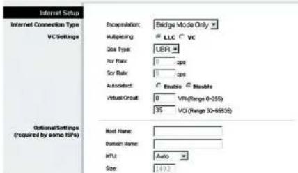
text_image
Internet Setup Internet Connection Type VC Settings Encapsulation: Bridge Mode Only Multiplexing: LLC VC Size Type: UER Por Rate: 0 dpi Sor Rate: 0 dpi AutoSelect: Enable Enable Virtual Circuit: 0 VPI (Range 0-255) 35 VCI (Range 30-685S1) Optional Settings (required by some IFRs) Model Name: Domain Name: MPL: Auto Size: 1492Figure 5-8 : Bridged Mode Only (Bridged Mode uniquement)
text_image
Optional Settings (required by some RRs) Host Name: Domain Name: INTU: Auto Size: 1192 Network Setup Router IP Local IP Address: 192, 160, 1, 1 Submit Mask: 255, 255, 255, 0 Network Address Server Settings (DKCP) Local DHCP Server: Enable Enable DKCP Relay DHCP Relay Server: 0, 0, 0, 0 Starting IP Address: 192,188,5,0.4 Maximum Number of DHCP Users: 191 Client Lease Time: 0 minutes (0 means one day) Static DNS 1: 0, 0, 0, 0 Static DNS 2: 0, 0, 0, 0 Static DNS 3: 0, 0, 0, 0 WING: 0, 0, 0, 0 Time Setting Time Zone: (GMT-08:00 Pacific Time (USA & Canada)) Time Interval: 36.00 seconds Automatically adjust clock for devight saving changestext_image
LINKSYS A Minnesota Web Operating, Inc. Setup Wireless-C-ABSL Home Gateway 0002300 Setup Wireless Security Access Restrictions Applications & Gaming Administration Status Wireless 0005 Service ODS Service DyTDRS.org User Name: Password: Host Name: Internet P Address: Status Save Settings Cancel Change More Data SettingsFigure 5-10 : DynDNS.org

text_image
LINKSYS A Division of Class System, Inc. Setup DMS Service: 170.com E-mail Address: Password: Domain Name: Internet IP Address: Status: Save Settings Cancel Changes Microsoft Access Requirements Applications & Clearing Administration Status Send Settings Cancel ChangesFigure 5-11 : TZO.com
text_image
LINKSYS A Access of Our System, Inc. Setup Wireless ADSL Network Setting Status Setup Wireless Security Access Apple Store S Connection Administration Status Save Settings Cancel Changes Add Existing Setting Active Setting Operating Mode NA: Enabled Disabled RIP: Enabled Disabled Send Default Route Enable Disabled Interloc TransNet RIP Version: 0x0x1 Receiving RIP Version: 0x0x1 MultiBand or Broadcast: 5x0x0x1 Static Routing Select set number: 1 Delete This Entry: Destination P Address: 0 0 0 0 Submit Week: 0 0 0 0 Outmove: 0 0 0 0 Map Count: 1 Show Routing Telephone Save Settings Cancel Changes Save Settings Data Sourcestext_image
LINKSYS® A Division of Data Systems, Inc. Windows U-ADSL Name Category: Windows Wireless Status Wireless Security Access Accessories Applications & Settings Administration Value Main Network Settings Wireless Network Mode: Mixed Wireless Network Name (SDD) Linksys Wireless Channel: -2.47376 Wireless SDC Broadcast: Enable Disable Save Settings Cancel Changes New Data Pointstext_image
LINKSYS A Server of Data Systems, Inc. Wireless C: A02L Name Category: WINSU.SIC Setup Wireless Security Access Networks Applications Services Administration Status Wireless Security Wireless Security Wireless Security Wireless Security Secure Note: MISA, Fox-Edward Key VISA Shared Key: Drive Key Renewal: 3450 seconds Sare Settings Cancel Changes Name: Sare Settingstext_image
LINKSYS A Network of Data Systems, Inc. Wireless G ADSL Name Database WAV2016 Setup Windows Security Access Accessories Applications & Settings Administration Status Wireless Security Wireless Security Security module: WEP Actual Transaction Key 8 1 2 3 4 HP Duration: 54 bits 10 hex digits Peripherals: Generate Key 1: Key 2: Key 3: Key 4: Save Settings Cancel Changes Name: Save Settings Cancel ChangesFigure 5-16 : WEP
text_image
LINKSYS A License of Data Security, Inc. Wireless C: A8001 Wireless Gateway Setup Welcome Security Access Access Resources Application & Corning Administration Status Allow All Send/Ret Access Present computers Idet Section from accessing the wireless network Permit only computers Idet Section to access the wireless network Add MLC Address Access List Save Settings Cancel Changes Next Data Securitytext_image
MAC Address Filter List Enter MAC Address Format: xxxxxxxxxx/xxxxxx xxxxxx MAC 01: MAC 11: MAC 02: MAC 12: MAC 03: MAC 13: MAC 04: MAC 14: MAC 05: MAC 15: MAC 06: MAC 16: MAC 07: MAC 17: MAC 08: MAC 18: MAC 09: MAC 19: MAC 10: MAC 20: Wireless Client MACList Save Settings Cancel ChangesVPN Passthrough (Intercommunication VPN)
text_image
LINKSYS® A Division of Our System, Inc. Security Wireless C: ADSL Wireless (Locking) Setup Windows Security Access Buildings Applications & Gaming Administration Status VRS PassThrough IPSC PassThrough Enable Enable IPHD PassThrough Enable Enable IPSP PassThrough Enable Enable L2IP PassThrough Enable Enable Firewall Firewall Protection Enable Enable File Proxy Filter Cookies File Area Assets Play Amount Block WIFI Requests Disk Anonymous Internal Requests View Logs Save Settings Cancel Changes More... Data Sizestext_image
System Log Firewall Log ▼ Clear pageRefresh Clear pageRefresh Previous Page NextPagetext_image
LINKSYS A License of Data System, Inc. Access Restrictions Windows C:\APSSL\Apache Catalogue VIRCUINS Status Default Access Normal Access Policy: 10 Delete Summary Status Enable Enable Enter Policy Name: Kice Edit List of PCI Deny Allow Internet access during selection and hours Everyday Sun Mon Tue Wed Tue Fri Sat Time 24 Hours From To To Website Blocking by SSL Address Website Blocking by Raymond Blocked Service None - None - Add/Edit Service Save Settings Cancel Changes Menu... Save Settings Cancel ChangesFigure 5-23 : Internet Access (Accès Internet)

text_image
Internet Policy Summary No. Policy Name Days Time of Day Ductors 1 - S W T W T P F - 2 - S W T W T P B - 3 - S W T W T P B - 4 - S W T W T P B - 5 - S W T W T P B - 6 - S W T W T P B - 7 - S W T W T P B - 8 - S W T W T P B - 9 - S W T W T P B - 10 - S W T W T P B - Closetext_image
List of PCs Enter MAC Address of the PCs in this format:xxxxxxxxxxxx MAC 01: 00:03:00:00:00:00 MAC 02: 00:03:00:00:00:00 MAC 03: 00:03:00:00:00:00 MAC 04: 00:03:00:00:00:00 MAC 05: 00:09:00:01:00:00 MAC 06: 00:09:00:01:00:00 MAC 07: 00:09:00:01:00:00 MAC 08: 00:09:00:01:00:00 Enter the IP Address of the PCs IP 01: 192.168.1 [ ] IP 04: 192.168.1 [ ] IP 02: 192.168.1 [ ] IP 05: 192.168.1 [ ] IP 03: 192.168.1 [ ] IP 06: 192.168.1 [ ] Enter the IP Range of the PCs IP Range 01: 192.168.1 [ ] IP Range 02: 192.168.1 [ ] IP Range 03: 192.168.1 [ ] Save Settings Cancel Changestext_image
LINKSYS® A CNTM & SICN SPATR, INC. Applications & Gaming Windows & OS/MI Home Gateway Watches: Stop Wireless Security Access Reprovement Application & Administration Status Port Range Forwarding Port Range Application Start End Protocol P Address Enable P to P Both 102.988.1.P ✓ P to P Both 102.988.1.P ✓ P to P Both 102.988.1.P ✓ P to P Both 102.988.1.P ✓ P to P Both 102.988.1.P ✓ P to P Both 102.988.1.P ✓ P to P Coth 102.988.1.P ✓ P to P Both 102.988.1.P ✓ P to P Both 102.988.1.P ✓ P to P Both 102.988.1.P ✓ Save Settings Cancel ChangesFigure 5-28 : Port Range Forwarding (Transfert de connexion)
text_image
LINKSYS A Software Of Clear Solutions Inc. Applications & Gaming Windows C: ATE, Home Catalogue VINCULAC Setup Wireless Security Access Applications Application Administration Status Begined: Forwarding End: Forwarding End: Back Post Trapping Triggered Range Forwarded Range Application Start/Part End/Part Start/Part End/Part Enable 0 0 0 0 0 0 0 0 0 0 0 0 0 0 0 0 0 0 0 0 0 0 0 0 0 0 0 0 0 0 0 0 0 0 0 0 0 0 0 0 0 0 0 0 0 0 0 0 0 0 0 0 0 0 0 0 0 0 0 0 0 0 Save Settings CancelChanges Nexttext_image
LINKSYS © 2018 © 2019 Applications & Gaming Windows 6.1.3 (RISC) Home Gaming Status Windows Security Access Habit Hosting Cancel Options Habit Host IP Address HS.NIA (Cancel sign is 1.254) Save Settings Cancel Change Status Status HIS NIAFigure 5-30 : DMZ
text_image
LINKSYS A License or Data System, Inc. Applications &Gaming Network C: APOS (Home Catalogue) Setup Wireless Security Access Accessories Application Administration Move Data Protocoling User Page Monitoring Web Management C:\Users\NPs\Installed High priority Medium priority Low priority FTP C C C FTP C C C Tubrel C C C IMTP C C C RQFJ C C C Specific Port#1 C C C Specific Port#2 C C C Specific Port#3 C C C Save Settings Cancel ChangesFigure 5-31 : QS
Onglet Administration
Onglet Management (Gestion)
text_image
LINKSYS A License at Our System, Inc. Administration Network C: N354, Local Gateway Status Access Accession Application & Operating Administration Status Gateway Access Local Gateway Access Gateway Contact: Gateway Username: admin Gateway Password: No order to contact: Remote Management: Enable Enable Management Port: 1110000000000000000000000000000000000000000000000000000000000000000000000000000000000000000000 Remote Gateway Access Remote Upgrade SNBP SNBP: Enable Enable Device Name: NAQ354G Snap VU2 Get Community: public Set Community: private Top Management: Snap No: 592 5448 5 5928 SNP UNP: Enable Enable KMP Proof: Enable Enable VR, SN Management via VLAN: Enable Enable Save Settings Cancel Changes NextFigure 5-32 : Management (Gestion)

Onglet Reporting (Rapports)
Reporting (Rapports)
text_image
LINKSYS WELCOME NAME ORDER Administration Setup Wireless Security Access Authentication Applications & Settings Administration Status Exporting Log Enable Disable Logwriter IP Address: 952.9684 175.5 Email Address: Enable Disable Send or Service Threshold: 30% events (20 - 100) SMTP Mail Server: Send Address for Alert Logs: Return Email Address: View Logs Save Settings Cancel Changes Send to: 100% Send to: 100%Figure 5-34 : Reporting (Rapports)
Ping Test (Test Ping)
Ping Test Parameters (Paramètres de test Ping)
text_image
LINKSYS A Division of Data Systems, Inc. Administration Windows C: AOSL Server Catalogue Welcome: Group Winona Security Business Access Application & Settings Administration Status Background Security Degrades Help Help Ping Test Ping Test Parameters Ping Target P: 0 0 0 0 Ping Size: 40 Bytes Number of Progs: 1 (Change <=30) Ping Interval: 1500 Minocseconds Ping Duration: $500 Minocseconds Ping Event: Press Speed Packless/Reg Std Ping Result: Press Speed Packless/Reg Std Load Settings Cancel Changes Next Save SettingsFigure 5-36 : Ping Test (Test Ping)

text_image
LINKSYS A System is a CDS system, no. Administration Windows 6.0 ADS: Home Gateway WELCOME Group Windows Security Access Installations Applications A System Administration Status Backup Configuration Backup Restore Configuration Please select a file to restore Browse Restoretext_image
LINKSYS® Administration Software & ACTS, Master Calendar WALAWAY Setup Wireless Security Access Networks Application & Setting Administer Status Factory Defaults Maintenance Factory Defaults Yes No Save Settings Cancel Changestext_image
LINKSYS Administration Windows C: IBM, Viable Category Setup Wireless Security Access Application Administration Status Settings 1. Monitoring 2. Monitoring 3. Monitoring 4. Monitoring 5. Monitoring 6. Monitoring 7. Monitoring 8. Monitoring 9. Monitoring 10. Monitoring 11. Monitoring 12. Monitoring 13. Monitoring 14. Monitoring 15. Monitoring 16. Monitoring 17. Monitoring 18. Monitoring 19. Monitoring 20. Monitoring 21. Monitoring 22. Monitoring 23. Monitoring 24. Monitoring 25. Monitoring 26. Monitoring 27. Monitoring 28. Monitoring 29. Monitoring 30. Monitoring 31. Monitoring 32. Monitoring 33. Monitoring 34. Monitoring 35. Monitoring 36. Monitoring 37. Monitoring 38. Monitoring 39. Monitoring 40. Monitoring 41. Monitoring 42. Monitoring 43. Monitoring 44. Monitoring 45. Monitoring 46. Monitoring 47. Monitoring 48. Monitoring 49. Monitoring 50. Monitoring 51. Monitoring 52. Monitoring 53. Monitoring 54. Monitoring 55. Monitoring 56. Monitoring 57. Monitoring 58. Monitoring 59. Monitoring 60. Monitoring 61. Monitoring 62. Monitoring 63. Monitoring 64. Monitoring 65. Monitoring 66. Monitoring 67. Monitoring 68. Monitoring 69. Monitoring 70. Monitoring 71. Monitoring 72. Monitoring 73. Monitoring 74. Monitoring 75. Monitoring 76. Monitoring 77. Monitoring 78. Monitoring 79. Monitoring 80. Monitoring 81. Monitoring 82. Monitoring 83. Monitoring 84. Monitoring 85. Monitoring 86. Monitoring 87. Monitoring 88. Monitoring 89. Monitoring 90. Monitoring 91. Monitoring 92. Monitoring 93. Monitoring 94. Monitoring 95. Monitoring 96. Monitoring 97. Monitoring 98. Monitoring 99. Monitoring 100. Upgrade from: ABA Firmware Upgrade File Park Browse Warning: Upgrading Firmware loss for side drag take a few minutes, please end turn off the power or press the seat button. Upgrade from: BNT is interrupted! Upgrade Cancel/Upgrade OK Save/Restoretext_image
LINKSYS A DIVISION OF COLD SYSTEMS INC Administration Wireless G ADSL Master Customer WING-01-AC Setup Wireless Security Access Restructuring Applications & Content Administration Status Reboot Mode: Hard Soft Save Settings Cancel Changes Free Forward OKtext_image
LINKSYS A Division of Data Systems PC Status Windows 6. ARSL Name Catalog VINC:\ Setup VMware Security Access Restrictions Applications & Catalog Administration Status Local Network MAC Address: 90-85-88-AA-441F IP Address: 192.168.13 Submit Web: 353.265.361.8 DHCP Server: Enable Set IP Address: 192.168.154 DelP Address: 192.168.1204 DHCP Client Table ARSLARP Table RefreshFigure 5-42 : Local Network (Réseau local)
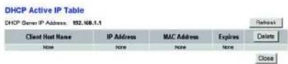
Figure 5-43 : Table IP active DHCP

Figure 5-44 : Tableau ARP/RARP
text_image
LINKSYS A Division of Data Systems, Inc. Status Wireless C: ADO Network Connection MACHINE Setup Wireless Security Accts Restriction Applications & Settings Administration Status Wireless Network Version: S2.04 MAC Address: "Bikkswe140" Mode: Mixed SDD: Single SHOP Server: Enable Channel: 0 Encryption Function: Disabled Wireless Clients Connected Reset Data Privacy AccessFigure 5-45 : Wireless (Sans fil)
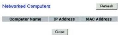
text_image
Networked Computers Refresh Computer Name IP Address MAC Address Closetext_image
LINKSYS A Division of SQL Server Status: Windows C:\ADSL\Basic\Category SQL Status: DSL Status: OFF DSL Initiation Mode: FVHD DSL Push Mode: FAST Downstream Rate: 90Hz/bps Upstream Rate: 100Hz/bps Downstream Margin: 63 db Upstream Margin: 3 db Downstream Line Information: 0 Upstream Line Alteration: 1 Downstream Transed Power: 8 Upstream Transed Power: 8 FVC Connection: Dissipation: FVC FACS Shipped Multiplicity: LLC Gcs: IGB Portfolio: 8 Soft Rate: 8 AutoBoost: Showable VR: 8 VO: 35 Enable: Yes FVC Status: Applied - OKFigure 5-47 : DSL Connection (Connexion DSL)
text_image
LINKSYS A Division of Data Services Inc. Administration Windows-C: ADS, Home Upgrade Group Wireless Security Resource Administrators Applications Application Settings Value Welcome Upgrade From: ADM Firmware Upgrade File Path: Browse Warning: Upgrading firmware from far-side may take a few minutes, please don't turn off the power or press the asset buttons Upgrades more WNT be interrupted! Upgrade Next > Cancel/Upgrade Help Save ProgramsThis product may be used in all EU countries (and other countries following the EU directive 1999/5/EC) without any limitation except for the countries mentioned below:
The Belgian Institute for Postal Services and Telecommunications (BIPT) must be notified of any outdoor wireless link having a range exceeding 300 meters. Please check http://www.bipt.be for more details.
In case the product is used outdoors, the output power is restricted in some parts of the band. See Table 1 or check http://www.art-telecom.fr/ for more details.
Ports Power (Alimentation), ADSL, Ethernet (1-4)
Boutons Un bouton Reset (Réinitialiser)
Voyants Power (Alimentation), Wireless (Sans fil),
Ethernet (1-4), DSL, Internet
A Division of Cisco Systems, Inc.

natural_image
White wireless router with dotted pattern and blue logo, no visible text or symbols on body2,4 GHz 802.11g
Wireless-G
Användarhandbok
Wireless
Fliken Administration 37
Fliken Status 43
Bilaga D: Uppgradera fast programvara 67
Bilaga E: Ordlista 68
Bilaga F: Information om regler 75
Bilaga G: Garantiinformation 81
Bilaga H: Specifikationer 82
Bilaga I: Kontaktinformation 84
Bild 3-3: Toppanel 8
Bild 3-4: Toppanel med tillvalsantenn 8
text_image
Collection of symbolic and decorative icons in a row, including stars, circles, and asterisks with various symbols.text_image
Line 1 2 Ethernet 3 4 Senset A Power 12/05/13natural_image
Blue mechanical lever handle with handle and lever (no text or symbols visible)Bild 3-3: Toppanel
natural_image
Front view of a white wireless router with a blue 'LINKSYS' logo and control panel (no readable text beyond branding)text_image
Collection of symbolic icons including stars, squares, and circles with various colors and symbolsÖversikt
natural_image
Front view of a network switch with Ethernet ports and a USB cable connector (no text or symbols visible)Bild 4-1: Anslut ADSL-Iinjen
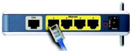
natural_image
Close-up of a network switch with Ethernet port and power cable (no text or symbols visible)natural_image
Close-up of a network switch with Ethernet ports and a USB cable (no text or symbols visible)Bild 4-3: Anslut strömmen
natural_image
Close-up of a network switch with four Ethernet ports and a power outlet (no visible text or symbols beyond labels)natural_image
Close-up of a network switch with four Ethernet ports and a cable connector (no visible text or symbols)Bild 4-5: Anslut strömmen

text_image
LINKSYS Setup Setup C:\MSCI\ New Community\ Setup Setup Include Import Access Access Type Access Type Network Connection Type IC Settings Displacement: RFC1463 Slotted ▼ Multimajor: ▲ LLC ▼ MC Use Type: I285 ▼ For Type: □ sec Set Type: □ sec Automated: □ Enable ▼ Enable Virtual Input: ▼ VR (Charge 2/000) □ VD (Charge 2/0000) P Settings □ Uses or IP address automatically □ Use the Minimum IP address Microsoft IP Address ▼ ▼ ▼ ▼ ▼ Submit Mode ▼ ▼ ▼ ▼ ▼ Delete ▼ ▼ ▼ ▼ ▼ ▼ Primary MCI ▼ ▼ ▼ ▼ ▼ ▼ Secondary DVI ▼ ▼ ▼ ▼ ▼ ▼ RFC1463 Slotted ▼ Optional Settings Prepared by time (V/V) User Address Custom Name: w(s): Auto Size: 11111 Network Settings Basic P Local P Address: 11111 11111 11111 11111 11111 11111 11111 11111 11111 11111 11111 11111 11111 11111 11111 11111 11111 11 Network Address Server Settings (RRC) Local TCP Server ▼ Static ▼ Static ▼ MCP Antiy TCP2 Rate Server ▼ Static ▼ Static ▼ TCP Antiy Register Features: TCP2Rate ▼ Normalization of TCP2 Rate ▼ Clear Time Time ▼ Active (Secure pin info) State: DNS 4 5 6 7 8 9 10 11 DNS: DNS 2 3 4 5 6 7 8 9 10 11 State: DNS 3 4 5 6 7 8 9 10 11 Time Setting True Size: [0.0.7.8.8.8] Static Time [USA Current] True Name: [0.0.7.8.8.8] seconds IP Automatic effect size to weight using chargestext_image
Internet Setup Internet Connection Type VC Settings Encapsulation: RFC 1483 Bridgad Multiplexing: LLC VC Gss Type: UBR For Rate: 0 fps Scr Rate: 0 fps Autoreset: Enable Enable Virtual Circuit: 0 VH (Range 0-255) 95 VH (Range 32-65535) IP SettingsObtain an IP Address Automatically
○ Use the following IP Address: Internet P Address: Submit Mask: Gateway: Primary DNS: Secondary DNS:Bild 5-3: RFC 1483 Bridged (Bryggkopplad) - Dynamisk IP-adress

text_image
Internet Setup Internet Connection Type VC Settings Encapsulation: RFC 1483 Bridged * Multiplexing: LLC VC Qoq Type: UBR * Pcs Rate: eps Sor Rate: eps Autodetect: Enable Enable Virtual Circuit: 0 VR (Range D-265) 35 VO (Range 32-8553) IP Settings Obtain an IP Address Automatically Use the following IP Address: Internet IP Address: 0 1 2 0 Subset Mask: 0 0 0 0 Gateway: 0 1 2 0 0 Primary DNS: 0 1 2 0 Secondary DNS: 0 1 2 0Bild 5-4: RFC 1483 Bridged (Bryggkopplad) - Statisk IP-adress
text_image
Internet Setup Internet Connection Type VC Settings Encapsulation: RFC 1483 Routed Multiplications: LLC VC Gas Type: UBR Por Rate: cps Cor Rate: cps Autodetect: Enable Disable Virtual Circuit: VR (Range 0-255) VCS VCI (Range 32-65535) IP Settings Internal IP Address: C 9 0 0 0 Submit Waste: C 9 0 0 0 Gateway: C 9 0 0 0 Primary DHCP: C 9 0 0 0 Secondary DHCP: C 9 0 0 0Bild 5-5: RFC 1483 Routed (Dirigerad)

text_image
Internet Setup Internet Connection Type VC Settings Encapsulation: RFC 2516 PPPuE Multiplicating: LLC VC Case Type: USBR Por Rate: cps Scr Rate: cps Auto detect: Enable Enable Virtual Circuit: 0 VPI (Range 0-255) 35 VCI (Range 32-85635) PPPuE Settings Service Name: User Name: Password: Connect on Demand: Max Time 20 Min. Keep Alive: Radial Period 20 Sec.Bild 5-6: RFC 2516 PPPoE
text_image
Internet Setup Internet Connection Type VC Settings Incorporation: Bridge Mode Only Multiporating: LLC VC Box Type: UER For Rate: 0 cps Box Rate: 0 cps AutoSelect: Enable Enable Virtual Circuit: 0 VRI (Range 0-255) 25 VCI (Range 32-65530) Optional Settings (required by some (50s) Host Name: Domain Name: WPU: Auto Size: 1192text_image
Optional Settings (required by some RRs) Host Name: Domain Name: INTU: Auto Size: 1192 Network Setup Router IP Local IP Address: 192, 160, 1, 1 Submit Mask: 255, 255, 255, 0 Network Address Server Settings (DKCP) Local DHCP Server: Enable Enable DKCP Relay DHCP Relay Server: 0, 0, 0, 0 Starting IP Address: 192,188,5,0.4 Maximum Number of DHCP Users: 191 Client Lease Time: 0 minutes (0 means one day) Static DNS 1: 0, 0, 0, 0 Static DNS 2: 0, 0, 0, 0 Static DNS 3: 0, 0, 0, 0 WING: 0, 0, 0, 0 Time Setting Time Zone: (GMT-08:00 Pacific Time (USA & Canada)) Time Interval: 36.00 seconds Automatically adjust clock for devight saving changestext_image
LINKSYS A license of DOS system, Inc. Setup Wireless (C:\BOS\ Guam\ Labing WELCOME) Setup Wireless Security Access Access Administration Applications Administration Status DONG Service DONG Service User Name: Password: Mail Name: Email ID: Address: Status: Save Settings Cancel Changes Store Bus Typetext_image
LINKSYS® LinkSYS - https://www.rkgs.com Setup Windows OS DNS Home Gateway VIRCUA Status Wireless Security Access Application Administration Status DNS Service 120.com E-mail Address Password Domain Name Name IP Address Show Show Settings Cancel/Change Show Settings Cancel/ChangeBild 5-11: TZO.com
Fliken Advanced Routing (Avancerad routing)
Advanced Routing (Avancerad routing)
text_image
LINKSYS® A Version of Data Systems, Inc. Setup Wireless APB Form Sets Settings Setup Wireless Security Available Access to Web Server Application & Connection Administration Status Send Settings Cancel Changes Add Existing Routing Advanced Routing Operating Mode NAS: Enabled Disabled RIP: Enabled Disabled Send Default Route Enable Disabled Interfac: Transient RIP Version: 100% Receiving RIP Version: 100% Multioid or Broadcast: Multioid Static Routing Select set number: 1 Delete This Entry Destination P Address: 0 0 0 0 Submit Mark: 0 0 0 0 Outflow: 0 0 0 0 Map Clock: 1 Show-Routing Tools Save Settings Cancel Changes More Save Settings Cancel ChangesBild 5-12: Advanced Routing (Avancerad routing)
text_image
LINKSYS A Network of Link Systems, Inc. Windows (AOS) Name: Community Wireless Setup Wireless Security Access Applications Applications & Learning Administration Value Send Settings Send Settings Send Settings Send Settings Wireless Networks Wireless Network Mode: Mixed Wireless Network Name (SDD): Linksys Wireless Channel: -2.070Hz Wireless SDD Broadcast: Enable Disable Save Settings Cancel Changes Send Settings Cancel Changestext_image
LINKSYS® A Verizon of Data Systems, Inc. Wireless Windows C: ADSL Home Gateway WINSYSYS Setup Wireless Security Access Accessories Applications & Settings Administration Status Basic Internet Settings Wireless Security Security Details Advanced Privacy Settings Wireless Security Secure Mode WINS (Pre-Shared Key) WNS Shared Key Secure Key Removal WINS seconds Save Settings Cancel Changes Name: SaaS Networktext_image
LINKSYS A Division of Data Systems, Inc. Wireless G. RDSL Home Security WRC2006 Setup Wireless Security Access Refreshless Applications & Settings Administration Status User Relationship Status Wireless Security Wireless Security Wireless Security Wireless Security Security Mode: IMEP Default Transmit Key: 1 2 3 4 IMEP Duration: 44 bits 10 hex digits Passive:\ Cananda Key 1: Key 2: Key 3: Key 4: Save Settings Cancel Changes More Save Settings Cancel ChangesBild 5-16: WEP
text_image
LINKSYS A wireless of Data Systems, Inc. Wireless C: A iOS Server Catalogue Settings Setup Information Security Access Resources Application & General Administration Status Wireless Network Access Allow All Install Access Present computers labeled from accessing the wireless network Present only computers labeled to access the wireless network OR MBC Address Access List Save Settings Direct Changes New Save Securitytext_image
MAC Address Filter List Enter MAC Address Format: xxxxxxxxxxxxxxxxxxxxxxxxxxxxxxxxxxxxxxxxxxxxxxxxxxxxxxxxxxxxxxxxxxxxxxxxxxxxxxxxxxxxxxxxxxxxxxxxxxxxxxxxxxxxxxxxxxxxxxxxxxxxxxxxxxxxxxxxxxxxxxxxxxxxxxxxxxxxxxxxxxxxxxxxxxxxxxxxxxxxxxxxxxxxxxxxxxxxxxxxxxxxxxxxxxxxxxxxxxxxxxxxxxxxxxxxxxxxxxxxxxxxxxxxxxxxxxxxxxxxxxxxxxxxxxxxxxxxxxxxxxxxxxxxxxxxxxxxxxxxxxxxxxxxxxxxxxxxxxxxxxxxxxxxxxxxxxxxxxxxxxxxxxxxxxxxxxxxxxxxxxxxxxxxxxxxxxxxxxxxxxxxxxxxxxxxxxxxxxxxxxxxxxxxxxxxxxxxxxxxxxxxxxxxxxxxxxxxxxxxxxxxxxxxxxxxxxxxxxxxxxxxxxxxxxxxxxxxxxxxxxxxxxxxxxxxxxxxxxxxxxxxxxxxxxxxxxxxxxxxxxxxxxxxxxxxxxxxxxxxxxxxxxxxxxxxxxxxxxxxxxxxxxxxxxxxxxxxxxxxxxxxxxxxxxxxxxxxxxxxxxxxxxxxxxxxxxxxxxxxxxxxxxxxxxxxxxxxxxxxxxxxxxxxxxxxxxxxxxxxxxxxxxxxxxxxxxxxxxxxxxxxxxxxxxxxxxxxxxxxxxxxxxxxxxxxxxxxxxxxxxxxxxxxxxxxxxxxxxxxxxxxxxxxxxxxxxxxxxxxxxxxxxxxxxxxxxxxxxxxxxxxxxxxxxxxxxxxxxxxxxxxxxxxxx MAC 01:_______________ MAC 02:_______________ MAC 03:_______________ MAC 04:_______________ MAC 05:_______________ MAC 06:_______________ MAC 07:_______________ MAC 08:_______________ MAC 09:_______________ MAC 10:_______________ MAC 11:_______________ MAC 12:_______________ MAC 13:_______________ MAC 14:_______________ MAC 15:_______________ MAC 16:_______________ MAC 17:_______________ MAC 18:_______________ MAC 19:_______________ MAC 20:_______________ Wireless Client MACList Save Settings Cancel ChangesBild 5-18: MAC Address Filter List (MAC-adressfilterlista)
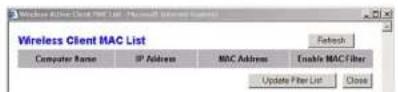
Bild 5-19: Wireless Client MAC List (Lista med trådlösa klienters MAC-adresser)
text_image
LINKSYS A Division of Data Systems, Inc. Security VLAN Breakthrough Phone PassThrough: Enable Enable PHD PassThrough: Enable Enable BIP PassThrough: Enable Enable USB PassThrough: Enable Enable Network Formal Protection: Enable Enable File Proxy File Codes File name Applics File Name Block PWM Programs Block Anonymous Internal Payments View URL Save Settings Cancel Changes Key: Save Options A Atext_image
System Log Firewall Log ▼ Clear pageRefresh Clear pageRefresh Previous Page NextPagetext_image
LINKSYS A Division of Data Systems, Inc. Access Restrictions Windows C:\APSQL\Apache Cataloging WELCOME Status Date Status Update Update Subscription Applicable & Closing Administration Status Internet Access Normal Access Policy: 10 Delete Summary Status: Enable Enable Enter Policy Name: Edit List of PCI Ica Down Allow Internet access during selected dates and hours. Begin Everyday: Sun Hon Tue Wed Thu Fri Sat Time: 34 Hours Free To Website Blocking by SSL Address Website Blocking by RePayment Blanked Service: None Name AdcyEdit Service Save Settings Cancel Changes Name Save Settings Cancel ChangesBild 5-23: Internet Access (Internet-åtkomst)
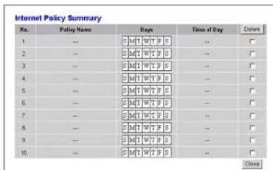
text_image
Internet Policy Summary No. Policy Name Days Time of Day Date 1 — 3:4:1:1 WTP S — □ 2 — 3:4:1:1 WT F S — □ 3 — 3:4:1:1 WT F S — □ 4 — 3:4:1:1 WT F S — □ 5 — 3:4:1:1 WT F S — □ 6 — 3:4:1:1 WT F S — □ 7 — 3:4:1:1 WT F S — □ 8 — 3:4:1:1 WT F S — □ 9 — 3:4:1:1 WT F S — □ 10 — 3:4:1:1 WT F S — □ Closetext_image
List of PCs Enter MAC Address of the PCs in this format: xxxxxxxxxxxxxx MAC 01: 00:03:00:00:00:00 MAC 02: 00:03:00:00:00:00 MAC 03: 00:03:00:00:00:00 MAC 04: 00:03:00:00:00:00 MAC 05: 00:03:00:01:00:00 MAC 06: 00:03:00:01:00:00 MAC 07: 00:03:00:01:00:00 MAC 08: 00:03:00:01:00:00 Enter the IP Address of the PCs IP 01: 192.168.1 [ ] IP 04: 192.168.1 [ ] IP 02: 192.168.1 [ ] IP 05: 192.168.1 [ ] IP 03: 192.168.1 [ ] IP 06: 192.168.1 [ ] Enter the IP Range of the PCs IP Range 01: 192.168.1 [ ] - [ ] IP Range 02: 192.168.1 [ ] - [ ] Save Settings Cancel ChangesBild 5-25: List of PCs (Lista med datorer)
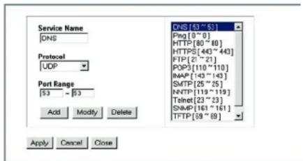
text_image
Service Name DNS Protocol UDP Port Range 53 - 53 Add Modify Delete DNS [53~53] Ping[0~0] HTTP [80~80] HTTPS[443~443] FTP[21~21] POP3 [110~110] IMAP [143~143] SMTP [25~25] NNTP [119~119] Telnet[23~23] SNMP [161~161] TFTP [59~59] Apply Cancel Closetext_image
LINKSYS A network in the system, Inc. Applications & Gaming Windows & iOS Home Calendar WARRANT: Setup Wireless Security Access Instructions Application & Service Administration Status Port Range Forwarding Port Range Application Start End Protocol P Address Enable 10 to 9 Both 102.168.1 F 10 to 9 Both 102.168.1 F 10 to 9 Both 102.168.1 F 10 to 9 Both 102.168.1 F 10 to 9 Both 102.168.1 F 10 to 9 Both 102.168.1 F Save Settings Cancel Changes BOS Data HistoryBild 5-28: Port Range Forwarding (Vidarebefordran av portintervall)
text_image
LINKSYS A Division of Data Centers, Inc. Applications & Gaming Windows 6: A/5C Home Gateway MACS/SVC Setup VMware Security Access Applications Administrations Status Start Port Forwarding - 100000000000000000000000000000000000000000000000000000000000000000000000000000000000 Port Setting Triggent and Range Forward and Range Application Start Port End Port Start port End Port Enable 30 to 3 33 to 3 34 to 3 35 to 3 36 to 3 37 to 3 38 to 3 39 to 3 40 to 3 41 to 3 42 to 3 43 to 3 44 to 3 45 to 3 46 to 3 47 to 3 48 to 3 49 to 3 50 to 3 51 to 3 52 to 3 53 to 3 54 to 3 55 to 3 56 to 3 57 to 3 58 to 3 59 to 3 60 to 3 61 to 3 62 to 3 63 to 3 64 to 3 65 to 3 66 to 3 67 to 3 68 to 3 69 to 3 70 to 3 71 to 3 72 to 3 73 to 3 74 to 3 75 to 3 76 to 3 77 to 3 78 to 3 79 to 3 80 to 3 81 to 3 82 to 3 83 to 3 84 to 3 85 to 3 86 to 3 87 to 3 88 to 3 89 to 3 90 to 3 91 to 3 92 to 3 93 to 3 94 to 3 95 to 3 96 to 3 97 to 3 98 to 3 99 to 3 100 to 3Bild 5-29: Port Triggering (Portutlösare)
text_image
LINKSYS A program of Data system, Inc. Applications &Gaming Windows C: 6015 Name Category Setup Wireless Security Access Application SPT/SP Programming Real Data Programming Data Storage Administration Move C Enabled R Enabled High priority Medding priority.Low priority FTP C E E FTP C E E Tubrel C E E SMTP C E E POP3 C E E Specific Port# C E E Specific Port# C E E Specific Port# C E E Specific Port# C E E Save Settings Cancel ChangesBild 5-31: QoS
Fliken Administration
Fliken Management (Hantering)
text_image
LINKSYS A License of Our System, Inc. Administration Windows C:\BSS\Home Gateway Status PRODUCS Security Access Reproducts Applications & Clearing Administration Status Management Pre-order to confirm Gateway Access Local Gateway Access Gateway Contact: 1 Gateway Timestamp: admin Gateway Password: **** Pre-order to confirm: **** Remote Gateway Access Remote Management: Enable Enable Management Port: ****** Allowed F: Remote Upgrade: Enable Enable Remote Upgrade SNXP SNXP: Enable Enable Device Name: NA0354G Step V/V2 Cell Community: public Jet Community: private Top Management: Tap Id: 197 244 2 188 SNP OPP: Enable Enable KMP Pray: Enable Enable VR, ZN Management via VLAN: Enable Enable Save Settings Cancel Changes NameFliken Reporting (Rapportering)
Reporting (Rapportering)
Email Alerts (Varningsmeddelanden via e-post)
text_image
LINKSYS C:\Users\Data\System\In Administration Setup Wireless Security Access Authentication Application & Settings Administration Server Reporting Log Enable " Enable" Logwriter IP Address: 992.5863 100 Email Alerts Enabled " Enabled" Email of Service Requests: 20 events (20 - 100) SMTP Mail Server: Email Address for Alert Logs: Return Email Address: View Logs Save Settings Cancel Changes Edit... Save Settings Cancel ChangesBild 5-34: Reporting (Rapportering)
text_image
LINKSYS A Division of Data System, Inc. Administration Windflow C: RISOL Press Data Gateway WINCLIAL Design Maintenance Security Access Accessories Applications & Settings Administrative Status Png Test Ping Text Parameters Ping Target F: 0 0 0 0 Ping Size: 62 Bytes Number of Prgs: 1 (Marge 1-100) Ping Internal: 1500 Milliseconds Ping Total: $500 Milliseconds Ping Result: Pkt Social PktBased/Avg Rdt Save Settings Cancel Change Win Save Numberstext_image
LINKSYS 2.000 @ Data Services, Inc. Administration Writing & ASSL Tools Library WACIFIC: Setup Wireless Security Restore Reinstalls Applicable & Charging Administration Store Backup Settings - Security - Reinstalls - Access Backup Configurations Backup Restore Configurations Power used a file restore... Restore Restore Data EnergyFliken Firmware Upgrade (Uppgradera fast programvara)
text_image
LINKSYS A Division of Data Specialist, Inc. Administration Windows & ADSL Tracker Minimum Setup Windows Security Accounts Security Tools Across Security Administration Views Maintenance Maintenance Staff Factory Default Restore Factory Defaults: Yes No Save Settings Cancel Changes Next Next Options Data Servicestext_image
LINKSYS 2019 Server Management Administration Setup Wireless Security Access Application Settings Administration Status Upgrade Focus: A/B Firmware Upgrade File Park Drive Warning: Upgrading Firmware has top side may run a few minutes. please don't run off the power or press the serial button Upgrade must NOT be interrupted! Upgrade Cancel/Upgrade OK Save AsburyBild 5-39: Firmware Upgrade (Uppgradera fast programvara)
text_image
LINKSYS A Software in your system is Windows 6 ADS, Master GPs Gateway WBS345 Administration Setup Services Security Access Accessories Applications & Controls Administration Status Download: Windows - Microsoft (F) - Microsoft Teams - Microsoft Internet - Google Reboot Mode: Hand Soft Save Settings Cancel Changes Save Options Cancel Changestext_image
LINKSYS A Review of Data Systems, Inc. Status Windows C: A05L Name Category Default Wireless Security Access Services Applications & Settings Administration Status Local Network RXC Address: 90-36.68-AA-9497 P Address: 192.08.1.1 Submit Work: 255.25.255.8 DHCP Server: Enable Sett P Address: 192.08.1.84 Del P Address: 192.08.1.251 DHCP Clients Table ANPSARP Table NetworkBild 5-42: Local Network (Lokalt nätverk)
text_image
LINKSYS A division of data systems, Inc. Status Windows 6.2013 Windows Catalysts MACHINE Setup Wireless Security Access Applications Applications & Settings Administration Status Wireless Network Version: SJB4 MAC Address: "Buckbox44" Mode: Mixed USB: Insigns DHCP Server: Enable Channel: 8 Inscription Function: Selected Wireless Clients Connected Return Data Source: A#Ntext_image
Networked Computers Refresh Computer Name IP Address MAC Address CloseBild 5-46: Networked Computers (Nätverksanslutna datorer)
IP Address (IP-adress): 192.168.1.50
Subnet Mask (Nätmask): 255.255.255.0
Gateway: 192.168.1.1
text_image
LINKSYS A Division of Chain System, Inc. Administration Setup Wireless Security Active Reinstatement Active/Active Accessories Administration Value Upgrade From LAN Firmware Upgrade File Path: Browse Warning: Upgrading from the side via a few minutes, please don't fun off the power or press the usual function. Upgrade most NOT be interrupted! Upgrade Cancel Upgrade OK Save AsburyBild D-1: Firmware Upgrade (Uppgradera fast programvara)
natural_image
Collection of black and white geometric symbols including stars, squares, circles, and rectangles (no text or labels)Portar Power, ADSL, Ethernet (1-4)
Knapp Reset
Kabeltyp KAT 5 UTP
Lysdioder Power, Wireless, Ethernet (1-4), DSL, Internet
DoS-skydd (Denial of Service)
DECLARATION OF CONFORMITY
With regard to the R&TTE Directive 1999/5/EC
According to EN 45014
Cisco-Linksys LLC
121 Theory Drive
Irvine, CA 92617
USA
Declares under our sole responsibility that the product,
Linksys WAG354G / Wireless-G ADSL Home Gateway (Annex A)
Variants: WAG354G-XX where XX may stand for BG, BT, DE, FR, EU, E1, SE or UK (where applicable)
Fulfills the essential requirements of Directive 1999/5/EC.
The following standards were applied:
EMC EN 301 489-1(08-2002); EN 301 489-17(08-2002)
EN 55022:1994+A1: 1995+A2: 1997, Class B;
EN 61000-3-2: 2000; EN 61000-3-3: 1995 + A1:2001
Radio EN 300 328 V1.6.1 (2004)
Health & Safety EN 60950 (2000)
The product carries the CE Mark:

Date & Place of Issue: May 5, 2005 – The Netherlands

text_image
FibelSignature:
Ivar Beljaars
EMEA Product Manager & Systems Engineer
Haarlerbergpark Haarlerbergweg 13-19 1101 CH Amsterdam Netherlands
Additional Information:
EMC Test Report
Radio Test Report
Safety Test Report
ADT Corp. Test Report Number: RM940322H02; May 05, 2005
ADT Corp. Test Report Number: RE940322H02; May 05, 2005
Cerpass Consultancy Corp. Test Report Number: 10001 122 001; April 01, 2005
DECLARATION OF CONFORMITY
With regard to the R&TTE Directive 1999/5/EC
According to EN 45014
Cisco-Linksys LLC
121 Theory Drive
Irvine, CA 92617
USA
Declares under our sole responsibility that the product,
Linksys WAG354G / Wireless-G ADSL Home Gateway (Annex B)
Variants: WAG354G-XX where XX may stand for BG, BT, DE, FR, EU, EI, SE or UK (where applicable)
Fulfills the essential requirements of Directive 1999/5/EC.
The following standards were applied:
EMC EN 301 489-1(08-2002); EN 301 489-17(08-2002)
EN 55022:1994+A1: 1995+A2: 1997, Class B;
EN 61000-3-2: 2000; EN 61000-3-3: 1995 + A1:2001
Radio EN 300 328 V1.6.1 (2004)
Health & Safety EN 60950 (2000)
The product carries the CE Mark:

Date & Place of Issue: May 5, 2005 – The Netherlands

text_image
BeeSignature:
Ivar Beljaars
EMEA Product Manager & Systems Engineer
Haarlerbergpark Haarlerbergweg 13-19 1101 CH Amsterdam Netherlands
Additional Information:
EMC Test Report
Radio Test Report
Safety Test Report
ADT Corp. Test Report Number: RM940322H02B; May 04, 2005
ADT Corp. Test Report Number: RE940322H02B; May 04, 2005
Cerpass Consultancy Corp. Test Report Number: 10001 131 001; April 29, 2005