
YZ125LC - Motorcycle YAMAHA - Free user manual and instructions
Find the device manual for free YZ125LC YAMAHA in PDF.


| Product type | Motocross (competition) |
| Brand | Yamaha |
| Model | YZ125LC |
| Dimensions (L × W × H) | 2 134 mm × 827 mm × 1 318 mm |
| Wheelbase | 1 438 mm |
| Seat height | 993 mm |
| Ground clearance | 400 mm |
| Curb weight | 94.5 kg |
| Engine | Single-cylinder 2-stroke, liquid-cooled, 124 cc |
| Bore × stroke | 54 mm × 54.5 mm |
| Compression ratio | 8.7 – 11.0:1 |
| Fuel system | Carburetor Mikuni TMX38SS, unleaded premium gasoline 95 RON |
| Fuel tank capacity | 8.0 L |
| Transmission | 5-speed constant mesh, wet multi-plate clutch |
| Brakes | Front (250 mm) and rear (245 mm) disc, DOT 4 fluid |
| Front suspension | Telescopic fork, 300 mm travel |
| Rear suspension | Swingarm (monocross), 315 mm travel |
| Ignition | CDI magneto, NGK BR9EG spark plug (resistor type) |
| Engine lubrication | Gasoline/oil mixture 30:1 (Yamalube 2-R) |
| Transmission oil | SAE 10W-30, type SE, capacity 0.70 L |
| Tires | Front 80/100-21, rear 100/90-19, pressure 100 kPa |
| Usage | Strictly for competition on closed circuit |
Frequently Asked Questions - YZ125LC YAMAHA
User questions about YZ125LC YAMAHA
0 question about this device. Answer the ones you know or ask your own.
Ask a new question about this device
Download the instructions for your Motorcycle in PDF format for free! Find your manual YZ125LC - YAMAHA and take your electronic device back in hand. On this page are published all the documents necessary for the use of your device. YZ125LC by YAMAHA.
USER MANUAL YZ125LC YAMAHA
OWNER'S SERVICE MANUAL
MANUEL D'ATELIER DU
PROPRIETAIRE
FAHRER-UND
WARTUNGS-HANDBUCH
OWNER'S SERVICE MANUAL
©2002 by Yamaha Motor Co., Ltd.
1st Edition, May 2002
All rights reserved. Any reprinting or unauthorized use without the written permission of Yamaha Motor Co., Ltd. is expressly prohibited.
Printed in Japan
YZ125(R)/LC
MANUEL D'ATELIER DU PROPRIETAIRE
©2002 Yamaha Motor Co., Ltd. 1ère Edition, Mai 2002
© 2002 by Yamaha Motor Co., Ltd. 1a Edizione, Mei 2002
Congratulations on your purchase of a Yamaha YZ series. This model is the culmination of Yamaha's vast experience in the production of pacesetting racing machines. It represents the highest grade of craftsmanship and reliability that have made Yamaha a leader.
This manual explains operation, inspection, basic maintenance and tuning of your machine. If you have any questions about this manual or your machine, please contact your Yamaha dealer.
NOTE:
As improvements are made on this model, some data in this manual may become outdated. If you have any questions, please consult your Yamaha dealer.
WARNING
PLEASE READ THIS MANUAL CAREFULLY AND COMPLETELY BEFORE OPERATING THIS MACHINE. DO NOT ATTEMPT TO OPERATE THIS MACHINE UNTIL YOU HAVE ATTAINED A SATISFACTORY KNOWLEDGE OF ITS CONTROLS AND OPERATING FEATURES AND UNTIL YOU HAVE BEEN TRAINED IN SAFE AND PROPER RIDING TECHNIQUES. REGULAR INSPECTIONS AND CAREFUL MAINTENANCE, ALONG WITH GOOD RIDING SKILLS, WILL ENSURE THAT YOU SAFELY ENJOY THE CAPABILITIES AND THE RELIABILITY OF THIS MACHINE.
INTRODUCTION
THIS MACHINE IS DESIGNED STRICTLY FOR COMPETITION USE, ONLY ON A CLOSED COURSE. It is illegal for this machine to be operated on any public street, road, or highway. Off-road use on public lands may also be illegal. Please check local regulations before riding.
SAFETY INFORMATION
- THIS MACHINE IS TO BE OPERATED BY AN EXPERIENCED RIDER ONLY.
Do not attempt to operate this machine at maximum power until you are totally familiar with its characteristics.
- THIS MACHINE IS DESIGNED TO BE RIDDEN BY THE OPERATOR ONLY.
Do not carry passengers on this machine.
- ALWAYS WEAR PROTECTIVE APPAREL.
When operating this machine, always wear an approved helmet with goggles or a face shield. Also wear heavy boots, gloves, and protective clothing. Always wear proper fitting clothing that will not be caught in any of the moving parts or controls of the machine.
- ALWAYS MAINTAIN YOUR MACHINE IN PROPER WORKING ORDER.
For safety and reliability, the machine must be properly maintained. Always perform the pre-operation checks indicated in this manual. Correcting a mechanical problem before you ride may prevent an accident.
NOTICE IMPORTANTE
Always turn off the engine while refueling. Take care to not spill any gasoline on the engine or exhaust system. Never refuel in the vicinity of an open flame, or while smoking.
- GASOLINE CAN CAUSE INJURY.
If you should swallow some gasoline, inhale excess gasoline vapors, or allow any gasoline to get into your eyes, contact a doctor immediately. If any gasoline spills onto your skin or clothing, immediately wash skin areas with soap and water, and change your clothes.
- ONLY OPERATE THE MACHINE IN AN AREA WITH ADEQUATE VENTILATION.
Never start the engine or let it run for any length of time in an enclosed area. Exhaust fumes are poisonous. These fumes contain carbon monoxide, which by itself is odorless and colorless. Carbon monoxide is a dangerous gas which can cause unconsciousness or can be lethal.
- PARK THE MACHINE CAREFULLY; TURN OFF THE ENGINE.
Always turn off the engine if you are going to leave the machine. Do not park the machine on a slope or soft ground as it may fall over.
- PROPERLY SECURE THE MACHINE BEFORE TRANSPORTING IT.
When transporting the machine in another vehicle, always be sure it is properly secured and in an upright position and that the fuel cock is in the "OFF" position. Otherwise, fuel may leak out of the carburetor or fuel tank.
- L'ESSENCE EST HAUTE-MENT INFLAMMABLE.
This manual will provide you with a good basic understanding of features, operation, and basic maintenance and inspection items of this machine. Please read this manual carefully and completely before operating your new machine. If you have any questions regarding the operation or maintenance of your machine, please consult your Yamaha dealer.
NOTE:
This manual should be considered a permanent part of this machine and should remain with it even if the machine is subsequently sold.
EC060000
NOTICE
Some data in this manual may become outdated due to improvements made to this model in the future. If there is any question you have regarding this manual or your machine, please consult your Yamaha dealer.
EC070001
F.I.M. MACHINE WEIGHTS:
Weights of machines without fuel
The minimum weights for motocross machines are:
for the class 125 cc......minimum
88 kg (194 lb)
for the class 250 cc......minimum
98 kg (216 lb)
for the class 500 cc......minimum
102 kg (225 lb)
In modifying your machine (e.g., for weight reduction), take note of the above limits of weight.
AU NOUVEAU PROPRIETAIRE
Motocross- Maschine ist:
für 125 cc Klasse
......Mindest
88 kg (194 lb)
für 250 cc Klasse
......Mindest
98 kg (216 lb)
für 500 cc Klasse
......Mindest
102 kg (225 lb)
The Safety Alert Symbol means ATTENTION! BECOME ALERT! YOUR SAFETY IS INVOLVED!
WARNING
Failure to follow WARNING instructions could result in severe injury or death to the machine operator, a bystander, or a person inspecting or repairing the machine.
CAUTION:
A CAUTION indicates special precautions that must be taken to avoid damage to the machine.
NOTE:
A NOTE provides key information to make procedures easier or clearer.
EC082000
FINDING THE REQUIRED PAGE
-
This manual consists of seven chapters; "General Information", "Specifications", "Regular inspection and adjustments", "Engine", "Chassis", "Electrical" and "Tuning".
-
The table of contents is at the beginning of the manual. Look over the general layout of the book before finding then required chapter and item.
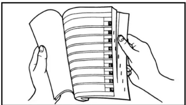
Bend the book at its edge, as shown, to find the required fore edge symbol mark and go to a page for required item and description.
COMMENT UTILISER CE MANUEL
INFORMATIONS PARTICULIEREMENT IMPORTANTES
!
All of the procedures in this manual are organized in a sequential, step-by-step format. The information has been complied to provide the mechanic with an easy to read, handy reference that contains comprehensive explanations of all disassembly, repair, assembly, and inspection operations.
In this revised format, the condition of a faulty component will precede an arrow symbol and the course of action required will follow the symbol, e.g.,
•Bearings
Pitting/Damage→Replace.
EC084002
HOW TO READ DESCRIPTIONS
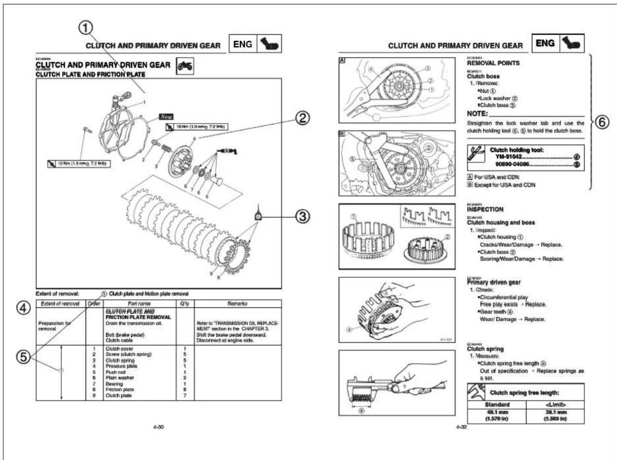
To help identify parts and clarify procedure steps, there are exploded diagrams at the start of each removal and disassembly section.
- An easy-to-see exploded diagram ①is provided for removal and disassembly jobs.
- Numbers ② are given in the order of the jobs in the exploded diagram. A number that is enclosed by a circle indicates a disassembly step.
-
An explanation of jobs and notes is presented in an easy-to-read way by the use of symbol marks ③. The meanings of the symbol marks are given on the next page.
-
A job instruction chart ④ accompanies the exploded diagram, providing the order of jobs, names of parts, notes in jobs, etc.
-
Extent of removal ⑤ is provided in the job instruction chart to save the trouble of an unnecessary removal job.
-
For jobs requiring more information, the step-by-step format supplements ⑥ are given in addition to the exploded diagram and job instruction chart.
FORMAT DU MANUEL
ILLUSTRATED SYMBOLS (Refer to the illustration)
Illustrated symbols ① to ⑦ are designed as thumb tabs to indicate the chapter's number and content.
①General information
②Specifications
③Regular inspection and adjustments
④Engine
⑤Chassis
⑥Electrical
⑦Tuning
Illustrated symbols ⑧to ⑭are used to identify the specifications appearing in the text.
⑧ With engine mounted
⑨Special tool
⑩Filling fluid
⑪Lubricant
⑫Tightening
⑬Specified value, Service limit
⑭Resistance (Ω), Voltage (V), Electric current (A)
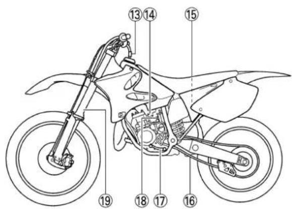
Illustrated symbols ⑮ to ⑲ in the exploded diagrams indicate grade of lubricant and location of lubrication point.
⑮Apply transmission oil
⑯Apply engine mixing oil
⑰Apply molybdenum disulfide oil
⑱Apply lightweight lithium-soap base grease
⑲Apply molybdenum disulfide grease
Illustrated symbols ⑳to ㉑in the exploded diagrams indicate where to apply a locking agent and where to install new parts.
⑳Apply locking agent (LOCTITE ®)
②1Use new one
SYMBOLES GRAPHIQUES (Voir l'illustration)
CHECKING OF CONNECTION ....1-6
SPECIAL TOOLS....1-7
CONTROL FUNCTIONS....1-9
FUEL AND ENGINE MIXING OIL....1-12
STARTING AND BREAK-IN 1-13
TORQUE-CHECK POINTS....1-16
CLEANING AND STORAGE 1-17
CHAPTER 2
SPECIFICATIONS
GENERAL SPECIFICATIONS ......2-1
MAINTENANCE SPECIFICATIONS .....2-3
GENERAL TORQUE SPECIFICATIONS..2-12
DEFINITION OF UNITS ......2-12
CABLE ROUTING DIAGRAM 2-13
CHAPTER 3
REGULAR INSPECTION
AND ADJUSTMENTS
MAINTENANCE INTERVALS....3-1
PRE-OPERATION INSPECTION AND
MAINTENANCE....3-4
ENGINE....3-5
CHASSIS....3-17
ELECTRICAL....3-38
TABLES DES MATIERES
CHAPITRE 1 RENSEIGNEMENTS GENERAUX
DESCRIPTION 1-1
IDENTIFICATION DE LA MACHINE ...1-2
INFORMATIONS IMPORTANTES .....1-3
VÉRIFICATION DES CONNEXIONS ....1-6
OUTILS SPECIAUX....1-7
FONCTIONS DES COMMANDES......1-9
ESSENCE ET HUILE DE MELANGE DU MOTEUR....1-12
MISE EN MARCHE ET RODAGE .....1-13
POINTS DE VERIFICATION DE COUPLE DE SERRAGE....1-16
NETTOYAGE ET RANGEMENT.....1-17
CHAPITRE 2 CARACTERISTIQUES
CARACTERISTIQUES GENERALES....2-1
CARACTERISTIQUES D'ENTRETIEN .2-3
SPECIFICATIONS GENERALES DE COUPLE....2-12
DEFINITION DES UNITES ......2-12
SCHEMA DE CHEMINEMENT DES CABLES 2-13
CHAPITRE 3 VERIFICATION ET REGLAGES COURANTS
PROGRAMME D'ENTRETIEN....3-1
INSPECTION ET ENTRETIEN AVANT UTILISATION ....3-4
MOTEUR 3-5
PARTIE CYCLE 3-17
PARTIE ELECTRIQUE 3-38
INHALTSVERZEICHNIS
CARBURETOR AND REED VALVE....4-7
CYLINDER HEAD, CYLINDER AND
PISTON 4-17
CLUTCH AND PRIMARY DRIVEN
GEAR 4-30
KICK AXLE, SHIFT SHAFT AND
PRIMARY DRIVE GEAR....4-38
YPVS GOVERNOR....4-46
WATER PUMP 4-49
CDI MAGNETO....4-53
ENGINE REMOVAL....4-57
CRANKCASE AND CRANKSHAFT......4-62
TRANSMISSION, SHIFT CAM AND
SHIFT FORK....4-69
CHAPTER 5 CHASSIS
FRONT WHEEL AND REAR WHEEL .....5-1
FRONT BRAKE AND REAR BRAKE.....5-10
FRONT FORK....5-26
HANDLEBAR....5-39
STEERING 5-46
SWINGARM 5-51
REAR SHOCK ABSORBER....5-59
CHAPITRE 4 MOTEUR
SELLE, RESERVOIR A ESSENCE ET COUVERCLES LATERAUX....4-1
TUYAU D'ECHAPPEMENT ET SILENCIEUX ....4-3
RADIATEUR....4-4
CARBURATEUR ET SOUPAPE FLEXIBLE ....4-7
CULASSE, CYLINDRE ET PISTON .....4-17
EMBRAYAGE ET PIGNON MENE PRIMAIRE....4-30
AXE DE DEMARREUR AU PIED, ARBRE DE SELECTEUR ET PIGNON DE TRANSMISSION PRIMAIRE ....4-38
REGULATEUR YPVS....4-46 POMPE A EAU ....4-49
MAGNETO CDI....4-53
DEPOSE DU MOTEUR ....4-57 CARTER ET VILEBREQUIN....4-62
BOITE A VITESSES, BARILLET DE SELECTEUR ET FOURCHETTE ...4-69
KAPITEL 4 MOTOR
CARBURATORE E VALVOLA A LAMELLA 4-7
TESTA CILINDRO, CILINDRO E PISTONE....4-17
FOURCHE AVANT....5-26
GUIDON....5-39
DIRECTION 5-46
BRAS OSCILLANT....5-51
AMORTISSEUR ARRIERE....5-59
CHAPITRE 7 MISE AU POINT
MOTEUR ....7-1 PARTIE CYCLE ....7-14
①Clutch lever
②"ENGINE STOP" button
③Front brake lever
④Throttle grip
⑤Radiator cap
⑥Fuel tank cap
⑦Kick starter
⑧Fuel tank
⑨Radiator
⑩Coolant drain bolt
⑪Check bolt (Transmission oil level)
⑫Rear brake pedal
⑬Valve joint
⑭Fuel cock
⑮Air cleaner
⑯Drive chain
⑰Shift pedal
⑱Starter knob
⑲Front fork
NOTE:
• The machine you have purchased may differ slightly from those shown in the following.
- Designs and specifications are subject to change without notice.


RENSEIGNEMENTS GENERAUX
DESCRIPTION
There are two significant reasons for knowing the serial number of your machine:
-
When ordering parts, you can give the number to your Yamaha dealer for positive identification of the model you own.
-
If your machine is stolen, the authorities will need the number to search for and identify your machine.
EC121001
VEHICLE IDENTIFICATION NUMBER (For USA, CDN, AUS, NZ and E)
The vehicle identification number ①is stamped on the right of the steering head pipe.

natural_image
Technical line drawing of a mechanical assembly with labeled component (1), no readable text or symbols present.EC122001
FRAME SERIAL NUMBER
(For F, D, GB, I and ZA)
The frame serial number ①is stamped on the right of the steering head pipe.
natural_image
Technical line drawing of a mechanical assembly with no visible text or symbolsEC123001
ENGINE SERIAL NUMBER
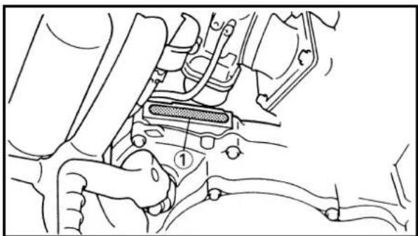
The engine serial number ①is stamped into the elevated part of the right-side of the engine.
EC124000
MODEL LABEL
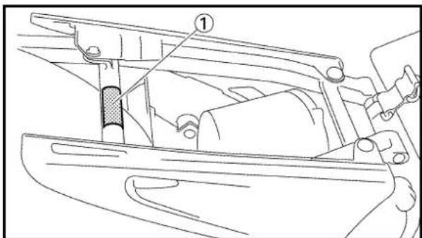
The model label ①is affixed to the frame under the rider's seat. This information will be needed to order spare parts.
IDENTIFICATION DE LA MACHINE
natural_image
Cartoon illustration of a mechanic working on a motorcycle with a base labeled 'SHEVARY MOTOR' (no text beyond label)
natural_image
Illustration of a mechanic working on mechanical parts with tools and equipment (no text or symbols)
natural_image
Cartoon illustration of a worker surrounded by mechanical components and question marks (no text or symbols)EC130000
IMPORTANT INFORMATION
EC131010
PREPARATION FOR REMOVAL AND DISASSEMBLY
- Remove all dirt, mud, dust, and foreign material before removal and disassembly. When washing the machine with high pressured water, cover the parts as follows.
•Silencer exhaust port
•Side cover air intake port
•Crankcase cover hole at the bottom
•Water pump housing hole at the bottom
-
Use proper tools and cleaning equipment. Refer to "SPECIAL TOOLS" section.
-
When disassembling the machine, keep mated parts together. They include gears, cylinders, pistons, and other mated parts that have been "mated" through normal wear. Mated parts must be reused as an assembly or replaced.
-
During the machine disassembly, clean all parts and place them in trays in the order of disassembly. This will speed up assembly time and help assure that all parts are correctly reinstalled.
-
Keep away from fire.
INFORMATIONS IMPORTANTES
PREPARATION POUR LA DEPO- SE ET DEMONTAGE
ALL REPLACEMENT PARTS
- We recommend to use Yamaha genuine parts for all replacements. Use oil and/or grease recommended by Yamaha for assembly and adjustment.
EC133000
GASKETS, OIL SEALS AND O-RINGS
- All gaskets, oil seals, and O-rings should be replaced when an engine is overhauled. All gasket surfaces, oil seal lips, and O-rings must be cleaned.
- Properly oil all mating parts and bearings during reassembly. Apply grease to the oil seal lips.
EC134000
LOCK WASHERS/PLATES AND COTTER PINS
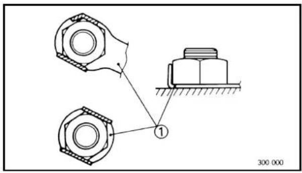
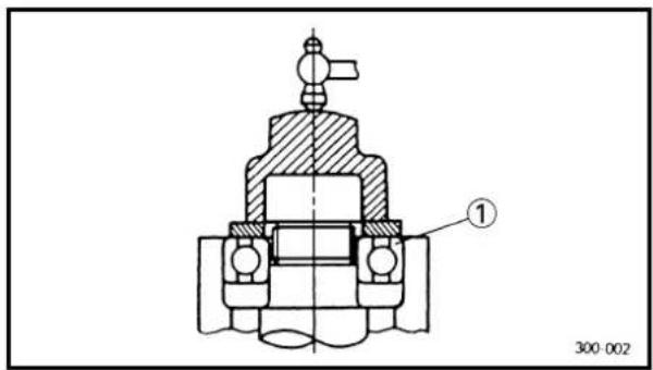
- All lock washers/plates ① and cotter pins must be replaced when they are removed. Lock tab(s) should be bent along the bolt or nut flat(s) after the bolt or nut has been properly tightened.
EC135001
BEARINGS AND OIL SEALS
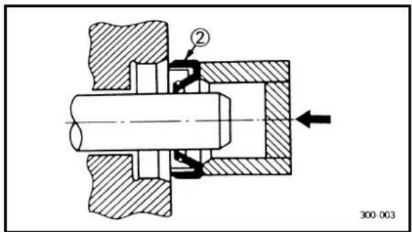
- Install the bearing (s) ① and oil seal (s) ② with their manufacturer's marks or numbers facing outward. (In other words, the stamped letters must be on the side exposed to view.) When installing oil seal(s), apply a light coating of light-weight lithium base grease to the seal lip(s). Oil the bearings liberally when installing.
CAUTION:
Do not use compressed air to spin the bearings dry. This causes damage to the bearing surfaces.
PIECES DE RECHANGE
EC136000
CIRCLIPS
- All circlips should be inspected carefully before reassembly. Always replace piston pin clips after one use. Replace distorted circlips. When installing a circlip ①, make sure that the sharp-edged corner ② is positioned opposite to the thrust ③ it receives. See the sectional view.
④Shaft
CIRCLIPS
natural_image
Two-panel line drawing showing hands holding small objects, one with a tool and the other with a tool (no text or symbols)

natural_image
Diagram of electrical connections showing a clamp, plug, and multimeter (no text or symbols)
natural_image
Diagram of a multimeter connected to two cable connectors with arrows indicating direction (no text or symbols present)EC1C0001
CHECKING OF CONNECTION
Dealing with stains, rust, moisture, etc. on the connector.
-
Disconnect: •Connector
-
Dry each terminal with an air blower.
-
Connect and disconnect the connector two or three times.
- Pull the lead to check that it will not come off.
-
If the terminal comes off, bend up the pin ① and reinsert the terminal into the connector.
-
Connect: •Connector
NOTE:
The two connectors "click" together.
- Check for continuity with a tester.
NOTE:
- If there in no continuity, clean the terminals.
- Be sure to perform the steps 1 to 7 listed above when checking the wireharness.
- For a field remedy, use a contact revitalizer available on the market.
- Use the tester on the connector as shown.
VÉRIFICATION DES CONNEXIONS
The proper special tools are necessary for complete and accurate tune-up and assembly. Using the correct special tool will help prevent damage caused by the use of improper tools or improvised techniques. The shape and part number used for the special tool differ by country, so two types are provided. Refer to the list provided to avoid errors when placing an order.
NOTE:
- For U.S.A. and Canada, use part number starting with "YM-", "YU-" or "ACC-".
- For others, use part number starting with "90890-".
| Part number Tool name / How to use Illustration | |||
| YU-1135-A, 90890-01135 | Crankcase separating toolThese tool is used to split the crankcase as well as remove the crankshaft from either case. | YU-1135-A | 90890-01135 |
| YM-1189, 90890-01189 Flywheel puller YM-1189 90890-01189This tool is used to remove the flywheel magneto. |  |  | |
| YU-1235, 90890-01235 Rotor holding toolThis tool is used when loosening or tightening the flywheel magneto securing nut. | YU-1235 90890-01235 | 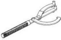 | |
| YU-3097, 90890-01252 Dial gauge and stand YU-3097 90890-01252YU-1256 Spark plug hole dial standThese tools are used to set the ignition timing. | YU-12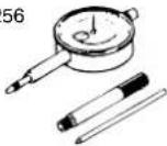 |  | |
| YU-90050, 90890-01274 PotYU-90050, 90890-01275 BoltYU-90062, 90890-01277 AdapterThese tools are used to install the crankshaft. | YU-90 | 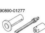 - - | |
| YU-1304, 90890-01304 Piston pin puller YU-1304 90890-01304This tool is used to remove the piston pin. |  | 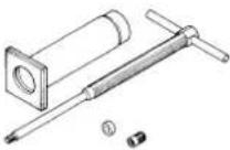 | |
| YM-1312-A, 90890-01312YM-01470, 90890-01470 | Fuel level gaugeFuel level gauge adaptorThis gauge is used to measure the fuel level in the float chamber. | YM-1312-AYM-01470 | 90890-0131290890-01470 |
| YU-24460-01, 90890-01325 YU-33984, 90890-01352 Adapter These tools are used for checking the cooling system. | Radiator cap tester YU-24460-01 90890-01325 | YU-33984 90890-01352 |  |
| YU-33975, 90890-01403 Ring nut wrench YU-33975 90890-0140 This tool is used when tighten the steering ring nut to specification. |  | 3 | |
| YM-1423, 90890-01423 Damper rod holder YM-1423 90890-01423 Use this tool to remove and install the damper rod. | 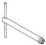 |  | |
| YM-01442, 90890-01442 Fork seal driver YM-01442 90890-01442 This tool is used when install the fork oil seal. | 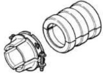 | 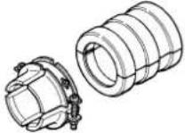 | |
| YU-3112-C, 90890-03112 Yamaha pocket tester Use this tool to inspect the coil resistance, output voltage and amperage. | YU-3112-C 90890-03112 | 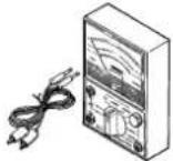 | |
| YM-91042, 90890-04086 Clutch holding tool YM-91042 90890-04086 This tool is used to hold the clutch when removing or installing the clutch boss securing nut. |  | 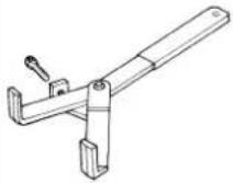 | |
| YM-34487 Dynamic spark tester 90890-06754 Ignition checker This instrument is necessary for checking the ignition system components. | |  | |
| ACC-QUICK-GS-KT 90890-85505 Quick gasket * YAMAHA Bond No. 1215 This sealant (Bond) is used for crankcase mating surface, etc. | ACC-QUICK-GS-KT | 90890-85505 | |
OUTILS SPECIAUX


EC150000
CONTROL FUNCTIONS
EC151000
"ENGINE STOP" BUTTON
The "ENGINE STOP" button ① is located on the left handlebar. Continue pushing the "ENGINE STOP" button till the engine comes to a stop.
EC152000
CLUTCH LEVER
The clutch lever ① is located on the left handlebar; it disengages or engages the clutch. Pull the clutch lever to the handlebar to disengage the clutch, and release the lever to engage the clutch. The lever should be pulled rapidly and released slowly for smooth starts.
EC153000
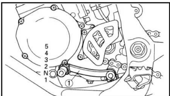
SHIFT PEDAL
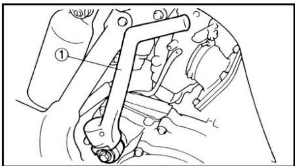
The gear ratios of the constant-mesh 5 speed transmission are ideally spaced. The gears can be shifted by using the shift pedal ①on the left side of the engine.
EC154000
KICK STARTER
Rotate the kick starter ①away from the engine. Push the starter down lightly with your foot until the gears engage, then kick smoothly and forcefully to start the engine. This model has a primary kick starter so the engine can be started in any gear if the clutch is disengaged. In normal practices, however, shift to neutral before starting.
EC155001
THROTTLE GRIP
The throttle grip ①is located on the right handlebar; it accelerates or decelerates the engine. For acceleration, turn the grip toward you; for deceleration, turn it away from you.
FONCTIONS DES COMMANDES
BOUTON D'ARRET DE MOTEUR "ENGINE STOP"

natural_image
Technical line drawing of a mechanical assembly with no visible text or symbols
EC156000
FRONT BRAKE LEVER
The front brake lever ① is located on the right handlebar. Pull it toward the handlebar to activate the front brake.
EC157000
REAR BRAKE PEDAL
The rear brake pedal ① is located on the right side of the machine. Press down on the brake pedal to activate the rear brake.
EC158001
FUEL COCK
The fuel cock supplies fuel from the tank to carburetor while filtering the fuel. The fuel cock has the two positions:
OFF: With the lever in this position, fuel will not flow. Always return the lever to this position when the engine is not running.
ON: With the lever in this position, fuel flows to the carburetor. Normal riding is done with the lever in this position.
EC159000
STARTER KNOB (CHOKE)
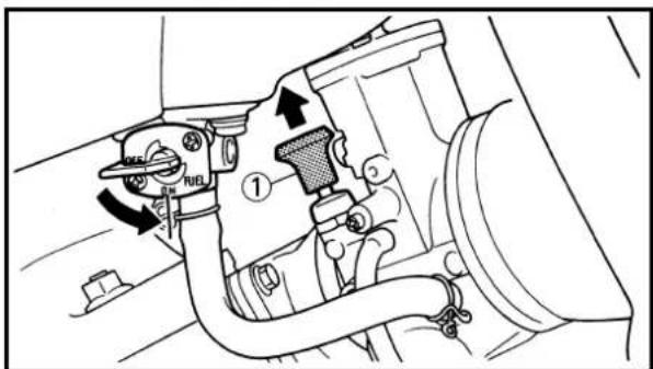
When cold, the engine requires a richer air-fuel mixture for starting. A separate starter circuit, which is controlled by the starter knob ①, supplies this mixture. Pull the starter knob out to open the circuit for starting. When the engine has warmed up, push it in to close the circuit.
LEVIER DE FREIN AVANT
natural_image
Simple line drawing of a triangular shape with a labeled point (1) at the base, no text or symbols present.
EC15R001
DETACHABLE SIDESTAND
This sidestand ①is used to support only the machine when standing or transporting it.
WARNING
- Never apply additional force to the side-stand.
- Remove this sidestand before starting out.
EC15F000
VALVE JOINT
This valve joint ① prevents fuel from flowing out and is installed to the fuel tank breather hose.
CAUTION:
In this installation, make sure the arrow faces the fuel tank and also downward.
EC15d000
COLLAR (tool for YPVS)
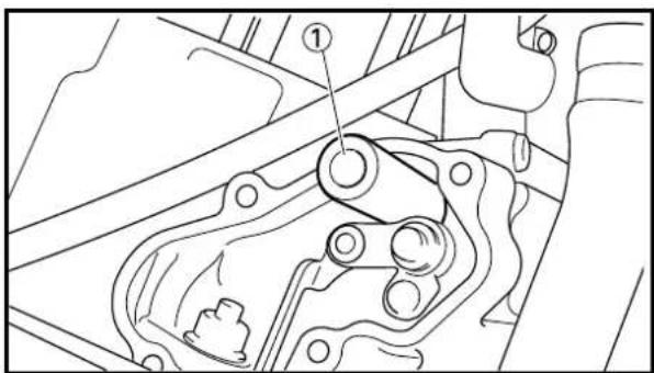
This collar ① is used to remove and install the push rod of the engine.
EC15e000
NIPPLE WRENCH
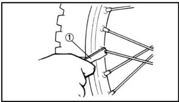
This nipple wrench ①is used to tighten the spoke.
BEQUILLE LATERALE AMOVIBLE
Mix oil with the gas at the ratio specified below. Always use fresh, name-brand gasoline, and mix the oil and gas the day of the race. Do not use premix that is more than a few hours old.

Recommended fuel:
Except for ZA:
Premium unleaded gasoline only with a research octane number of 95 or higher.
For ZA:
Premium gasoline
NOTE:
If knocking or pinging occurs, use a different brand of gasoline or higher octane grade.
CAUTION:
Never mix two types of oil in the same batch; clotting of the oil could result. If you wish to change oil types, be sure to drain the fuel tank and the carburetor float bowl of old premix prior to filling with the new type.


Fuel tank capacity:
8.0 L (1.76 Imp gal, 2.11 US gal)

Mixing oil
Recommended oil:
Yamalube "2-R"
(Yamalube racing 2-cycle oil)
Mixing ratio: 30 : 1
If unavailable, use an equivalent type of oil.
ESSENCE ET HUILE DE MELANGE DU MOTEUR
8,0 L (1,76 Imp gal, 2,11 US gal)

8,0 L (1,76 Imp gal, 2,11 US gal)

Before starting the machine, perform the checks in the pre-operation check list.
WARNING
Never start or run the engine in a closed area. The exhaust fumes are poisonous; they can cause loss of consciousness and death in a very short time. Always operate the machine in a well-ventilated area.
EC191001
STARTING A COLD ENGINE
- Shift the transmission into neutral.
- Turn the fuel cock to "ON" and full open the starter knob (CHOKE).
- With the throttle completely closed start the engine by kicking the kick starter forcefully with firm stroke.
- Run the engine at idle or slightly higher until it warms up: this usually takes about one or two minutes.
- The engine is warmed up when it responds normally to the throttle with the starter knob (CHOKE) turned off.
CAUTION:
Do not warm up the engine for extended periods.
EC193001
STARTING A WARM ENGINE
Do not operate the starter knob (CHOKE). Open the throttle slightly and start the engine by kicking the kick starter forcefully with firm stroke.
CAUTION:
Observe the following break-in procedures during initial operation to ensure optimum performance and avoid engine damage.
- Before starting the engine, fill the fuel tank with a break-in oil-fuel mixture as follows.

Mixing oil: Mixing ratio: Yamalube "2-R" 15:1
- Perform the pre-operation checks on the machine.
- Start and warm up the engine. Check the idle speed, and check the operation of the controls and the "ENGINE STOP" button.
- Operate the machine in the lower gears at moderate throttle openings for five to eight minutes. Stop and check the spark plug condition; it will show a rich condition during break-in.
- Allow the engine to cool. Restart the engine and operate the machine as in the step above for five minutes. Then, very briefly shift to the higher gears and check full-throttle response. Stop and check the spark plug.
- After again allowing the engine to cool, restart and run the machine for five more minutes. Full throttle and the higher gears may be used, but sustained full-throttle operation should be avoided. Check the spark plug condition.
- Allow the engine to cool, remove the top end, and inspect the piston and cylinder. Remove any high spots on the piston with #600 grit wet sandpaper. Clean all components and carefully reassemble the top end.
- Drain the break-in oil-fuel mixture from the fuel tank and refill with the specified mix.
- Restart the engine and check the operation of the machine throughout its entire operating range. Stop and check the spark plug condition. Restart the machine and operate it for about 10 to 15 more minutes. The machine will now be ready to race.
PROCEDURE DE RODAGE
- After the break-in or before each race, you must check the entire machine for loose fittings and fasteners as per "TORQUE-CHECK POINTS".
Tighten all such fasteners as required.
- When any of the following parts have been replaced, they must be broken in.
CYLINDER AND CRANKSHAFT:
About one hour of break-in operation is necessary.
PISTON, RING AND GEARS:
These parts require about 30 minutes of break-in operation at half-throttle or less.
Observe the condition of the engine carefully during operation.
ATTENTION:
PISTON, SEGMENT ET PIGNONS:
Frame construction Frame to rear frame Combined seat and tank Fuel tank to frame
Engine mounting Frame to engine Engine bracket to engine Engine bracket to frame
Steering Steering shaft to Steering shaft to frame handlebar Steering shaft to handle crown Handle crown to handlebar
Suspension Front Steering shaft to Front fork to handle crown front fork Front fork to under bracket
Rear For link type Assembly of links Link to frame Link to shock absorber Link to swingarm
Rear Installation of shock Shock absorber to frame absorber
Rear Installation of swingarm Tightening of pivot shaft
Wheel Installation of wheel Front Tightening of front axle Tightening of axle holder Rear Tightening of rear axle Wheel to sprocket
Brake Front Caliper to front fork Brake disc to wheel Tightening of union bolt Master cylinder to handlebar Tightening of air bleeder Rear Brake pedal to frame Brake disc to wheel Tightening of union bolt Master cylinder to frame Tightening of air bleeder
Fuel system ____ Fuel tank to fuel cock
NOTE:
Concerning the tightening torque, refer to “MAINTENANCE SPECIFICATIONS” section in the CHAPTER 2.
POINTS DE VERIFICATION DE COUPLE DE SERRAGE

CLEANING AND STORAGE
EC1B1000
CLEANING
Frequent cleaning of your machine will enhance its appearance, maintain good overall performance, and extend the life of many components.
- Before washing the machine, block off the end of the exhaust pipe to prevent water from entering. A plastic bag secured with a rubber band may be used for this purpose.
- If the engine is excessively greasy, apply some degreaser to it with a paint brush. Do not apply degreaser to the chain, sprockets, or wheel axles.
- Rinse the dirt and degreaser off with a garden hose; use only enough pressure to do the job.
CAUTION:
Excessive hose pressure may cause water seepage and contamination of wheel bearings, front forks, brakes and transmission seals. Many expensive repair bills have resulted from improper high pressure detergent applications such as those available in coin-operated car washers.
- After the majority of the dirt has been hosed off, wash all surfaces with warm water and a mild detergent. Use an old toothbrush to clean hard-to-reach places.
- Rinse the machine off immediately with clean water, and dry all surfaces with a soft towel or cloth.
- Immediately after washing, remove excess water from the chain with a paper towel and lubricate the chain to prevent rust.
- Clean the seat with a vinyl upholstery cleaner to keep the cover pliable and glossy.
- Automotive wax may be applied to all painted or chromed surfaces. Avoid combination cleaner-waxes, as they may contain abrasives.
- After completing the above, start the engine and allow it to idle for several minutes.
NETTOYAGE ET
RANGEMENT
NETTOYAGE
If your machine is to be stored for 60 days or more, some preventive measures must be taken to avoid deterioration. After cleaning the machine thoroughly, prepare it for storage as follows:
- Drain the fuel tank, fuel lines, and the carburetor float bowl.
- Remove the spark plug, pour a tablespoon of SAE 10W-30 motor oil in the spark plug hole, and reinstall the plug. With the engine stop switch pushed in, kick the engine over several times to coat the cylinder walls with oil.
- Remove the drive chain, clean it thoroughly with solvent, and lubricate it. Reinstall the chain or store it in a plastic bag tied to the frame.
- Lubricate all control cables.
- Block the frame up to raise the wheels off the ground.
- Tie a plastic bag over the exhaust pipe outlet to prevent moisture from entering.
- If the machine is to be stored in a humid or salt-air environment, coat all exposed metal surfaces with a film of light oil. Do not apply oil to rubber parts or the seat cover.
NOTE:
Make any necessary repairs before the machine is stored.
RANGEMENT
| Model name: YZ125LC (EUROPE) | YZ125R (USA)YZ125(R) (CDN, AUS, NZ, ZA) | |||
| Model code number: 5UN1 (USA, CDN, ZA) | 5UN2 (EUROPE)5UN4 (AUS, NZ) | |||
| Dimensions:Overall length 2,134 mm←2,130 mm←Overall width 827 mm← ←Overall height 1,318 mm 1,315 mm 1,311 mm 1,315 mmSeat height 993 mm←992 mm←Wheelbase 1,438 mm← ←Minimum ground clearance | USA, ZA | AUS, NZ E | EUROPE CDN | |
| (84.0 in) (83.9 in)(32.6 in)(51.9 in) (51.8 in) (51.6in) (51.8 in)(39.1 in) (39.1 in)(56.6 in)400 mm(15.7 in) (15.7 in) | ← | 398 mm | ← | |
| Basic weight:With oil and full fuel tank | 94.5 kg (208.3 lb) | |||
| Engine:Engine typeCylinder arrangementDisplacementBore × StrokeCompression ratioStarting system | Liquid cooled 2-stroke, gasolineSingle cylinder, forward inclined 124 cm^3 (4.36 Imp oz, 4.19 US oz) 54 × 54.5 mm ( 2.126 × 2.146 in )8.7~11.0 : 1Kick starter | |||
| Lubrication system: | Premix (30 : 1)(Yamalube 2-R) | |||
| Oil type or grade (2-Cycle):Transmission oilPeriodic oil changeTotal amount | Yamalube 4 (10W-30) or SAE 10W-30 type SEMotor oil0.65 L (0.57 Imp qt, 0.69 US qt)0.70 L (0.62 Imp qt, 0.74 US qt) | |||
| Coolant capacity (including all routes): | 0.95 L (0.84 Imp qt, 1.00 US qt) | |||
| Air filter: | Wet type element | |||
| Fuel:TypeTank capacity | Except for ZA: Premium unleaded gasolineonly with a research octanenumber of 95 or higherFor ZA: Premium gasoline8.0 L (1.76 Imp gal, 2.11 US gal) | |||
| Carburetor:Type/Manufacturer TMX | 38SS/MIKUNI | |||
| Spark plug:Type/Manufacturer BR9EG/NGK (resistance type)Gap 0.5~0.6 mm (0.020~0.024 in) | ||||
| Clutch type: Wet, multiple-disc | ||||
| Transmission:Primary reduction system GearPrimary reduction ratio 64/19 (3.368)Secondary reduction system Chain driveSecondary reduction ratio 49/13 (3.769)Transmission type Constant mesh, 5-speedOperation Left foot operationGear ratio: 1st 30/13 (2.308)2nd 28/15 (1.867)3rd 29/19 (1.526)4th 24/19 (1.263)5th 25/23 (1.087) | ||||
| Chassis:Frame typeCaster angleTrail 108 mm (4.25 in) 104 mm (4.09 in) | USA, ZA, AUS, NZ | EUROPE, CDN | ||
| Semi double cradle25.6° | ←25.4° | |||
| Tire:TypeSize (front)Size (rear)Tire pressure (front and rear) | With tube80/100-21 51M100/90-19 57M100 kPa (1.0 kgf/cm2, 15 psi) | |||
| Brake:Front brake typeOperation Right hand operationRear brake typeOperation Right foot operation | Single disc brakeSingle disc brake | |||
| Suspension:Front suspensionRear suspension | Telescopic forkSwingarm (link type monocross suspension) | |||
| Shock absorber:Front shock absorberRear shock absorber | Coil spring/oil damperCoil spring/Gas, oil damper | |||
| Wheel travel:Front wheel travelRear wheel travel | 300 mm (11.8 in)315 mm (12.4 in) | |||
| Electrical:Ignition system | CDI magneto | |||
EC212000
MAINTENANCE SPECIFICATIONS
EC212100
ENGINE
| Item Standard Limit | ||||||
| Cylinder head:Combustion chamber capacity 10.05 cmWarp limit | 3(0.354 Imp oz, 0.340 US oz)... | ...0.03 mm (0.0012 in) | ||||
| Cylinder:Bore size 54.000~54.014 mm 54.1 mm (2.130 in)Taper limitOut of round limit | (2.1260~2.1265 in)... | 0.05 mm (0.0020 in)0.01 mm (0.0004 in) | ||||
| Piston:Piston size/ 53.957~53.972 mm[IMAGE]Measuring point* 17.5 mm (0.69 in)Piston clearance 0.040~0.045 mm 0.1 mm (0.004 in)Piston offset 1.0 mm (0.039 in)/EX-side | (2.1243~2.1249 in)(0.0016~0.0018 in) | ......... | ||||
| Piston pin:Piston pin outside diameter 14.995~15.000 mm 14.975 mm(0.5904~0.5906 in) (0.5896 in) | ||||||
Piston ring:Sectional sketch Plain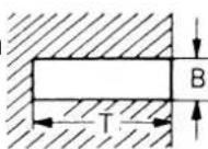 End gap (installed)Side clearance (installed) End gap (installed)Side clearance (installed) | B=1.0 mm (0.039 in)T=2.35 mm (0.093 in)0.5~0.7 mm (0.020~0.028 in)0.035~0.070 mm 0.1 mm (0.004 in)(0.0014~0.0028 in) | .........1.2 mm (0.047 in) | ||||
Crankshaft:Crank width “A”  Runout limit “C”Connecting rod big endside clearance “D”Small end free play “F” Runout limit “C”Connecting rod big endside clearance “D”Small end free play “F” | 55.90~55.95 mm(2.201~2.203 in)0.03 mm (0.0012 in)0.20~0.70 mm (0.008~0.028 in)0.8~1.0 mm (0.031~0.039 in) | ...0.05 mm (0.0020 in)...2.0 mm (0.08 in) | ||||
| Clutch:Friction plate thicknessQuantityClutch plate thicknessQuantityWarp limitClutch spring free lengthQuantityClutch housing thrust clearanceClutch housing radial clearanceClutch release method | 2.9~3.1 mm (0.114~0.122 in)81.5~1.7 mm (0.059~0.067 in)7...41.2 mm (1.622 in)50.20~0.25 mm (0.008~0.010 in)0.015~0.049 mm ...(0.0006~0.0019 in)Outer pull, rack and pinion pull | 2.8 mm (0.110 in).........0.2 mm (0.008 in)39.2 mm (1.543 in)............ | ||||
| Transmission:Main axle deflection limitDrive axle deflection limit | ... ... | 0.01 mm (0.0004 in)0.01 mm (0.0004 in) | ||||
| Shifter:Shifting type Cam drum and guide barGuide bar bending limit | ... | ...0.05 mm (0.0020 in) | ||||
Kick starter type: Kick and mesh typeKick clip friction force P=0.8~1.2 kg (1.8~2.6 lb) | ... ... | |||||
| Air filter oil grade (oiled filter): | Foam-air-filter oil or equivalent oil | ... | ||||
| Carburetor: USA, CDN, ZAType/Manufacturer TMXI.D. mark 5UN1 00 5UN2 10Main jet (M.J.) #410←Jet needle-clip position (J.N.) 6CHY6-82-3 6CHY6-82-4Cutaway (C.A.) 4.0Pilot jet (P.J.) #40Pilot air screw (P.A.S.) 2Valve seat size (V.S.) ø3.8 mm (0.15 in) ←Starter jet (G.S.) #80 ←Fuel level (F.L.) 9.5~10.5 mm ←(0.37~0.41 in) | AUS, NZ | EUROPE | ||||
| 38SS /MIKUNI | ||||||
Reed valve:Thickness*Valve stopper height  Valve bending limit Valve bending limit | 0.47 mm (0.019 in)8.2~8.6 mm (0.323~0.339 in)... | ... ...0.2 mm (0.008 in) | ||||
| Cooling:Radiator core size:WidthHeight (left)(right)ThicknessRadiator cap opening pressureRadiator capacity (total)Water pump:Type | 107.8 mm (4.24 in)240 mm (9.45 in)220 mm (8.66 in)32 mm (1.26 in)95~125 kPa(0.95~1.25 kg/cm2, 13.5~17.8 psi)0.63 L (0.55 Imp qt, 0.67 US qt)Single-suction centrifugal pump | |||||
| Part to be tightened Thread size Qty | Tightening torque | |||||
| Nm m·kg ft·lb | ||||||
| Spark plug M14 ×1.25 1 20 2.0 14Cylinder head (nut) M 8 ×1.25 5 28 2.8 20(stud) M 8 ×1.25 5 13 1.3 9.4 | ||||||
| Cylinder (nut)(stud) | M 8 × 1.25 | 4 | 30 | 3.0 | 22 | |
| M10 ×1.25 4 | 13 1.3 9.4 | |||||
| Power valve: | ||||||
| Cover | M 5 × 0.8 | 4 | 4 | 0.4 | 2.9 | |
| Link lever | M 4 × 0.7 | 1 | 4 | 0.4 | 2.9 | |
| Holder (power valve) | M 5 × 0.8 | 4 | 8 | 0.8 | 5.8 | |
| Push rod | M 5 × 0.8 | 1 | 5 | 0.5 | 3.6 | |
| Thrust plate | M 5 × 0.8 | 1 | 4 | 0.4 | 2.9 | |
| Governor fork | M 4 × 0.7 | 2 | 5 | 0.5 | 3.6 | |
| Housing | M 5 × 0.8 | 4 | 5 | 0.5 | 3.6 | |
| Impeller | M 8 ×1.25 1 | 14 1.4 10 | ||||
| Water pump housing cover | M 6 × 1.0 | 4 | 10 | 1.0 | 7.2 | |
| Coolant drain bolt | M 6 × 1.0 | 1 | 10 | 1.0 | 7.2 | |
| Radiator | M 6 × 1.0 | 6 | 10 | 1.0 | 7.2 | |
| Radiator panel | M 6 × 1.0 | 2 | 10 | 1.0 | 7.2 | |
| Radiator hose clamp | M 6 × 1.0 | 8 | 1 | 0.1 | 0.7 | |
| Air filter element | M 6 × 1.0 | 1 | 2 | 0.2 | 1.4 | |
| Carburetor joint | M 6 × 1.0 | 4 | 10 | 1.0 | 7.2 | |
| Air filter case | M 6 × 1.0 | 4 | 8 | 0.8 | 5.8 | |
| Air filter guide clamp | M 5 × 0.8 | 1 | 1 | 0.1 | 0.7 | |
| Read valve | M 3 × 0.5 | 6 | 1 | 0.1 | 0.7 | |
| Crankcase | M 6 × 1.0 | 12 | 14 | 1.4 | 10 | |
| Crankcase cover (right) | M 6 × 1.0 | 8 | 10 | 1.0 | 7.2 | |
| Crankcase cover (left) | M 6 × 1.0 | 5 | 5 | 0.5 | 3.6 | |
| Chain cover | M 6 × 1.0 | 2 | 5 | 0.5 | 3.6 | |
| Bearing plate cover | M 6 × 1.0 | 3 | 10 | 1.0 | 7.2 | |
| Holder | M 6 × 1.0 | 1 | 10 | 1.0 | 7.2 | |
| Oil check bolt | M 6 × 1.0 | 1 | 10 | 1.0 | 7.2 | |
| Oil drain bolt | M12 × 1.5 | 1 | 20 | 2.0 | 14 | |
| Kick starter | M 6 × 1.0 | 1 | 10 | 1.0 | 7.2 | |
| Cluch cover | M 6 × 1.0 | 6 10 1.0 7.2 | ||||
| Primary drive gear | M10 ×1.25 1 | 55 5.5 40 | ||||
| Clutch boss | M16 × 1.0 | 1 | 80 | 8.0 | 58 | |
| Clutch spring | M 6 × 1.0 | 5 | 10 | 1.0 | 7.2 | |
| Push lever axle | M 6 × 1.0 | 1 | 7 | 0.7 | 5.1 | |
| Drive sprocket | M16 × 1.0 | 1 | 65 | 6.5 | 47 | |
| Shift pedal | M 6 × 1.0 | 1 | 12 | 1.2 | 8.7 | |
| Bearing plate cover (shift cam) | M 6 × 1.0 | 2 | 10 | 1.0 | 7.2 | |
| Shift guide | M 6 × 1.0 | 2 10 1.0 7.2 | ||||
| Stopper lever | M 6 × 1.0 | 1 10 1.0 7.2 | ||||
| Segment | M 8 ×1.25 1 | 30 3.0 22 | ||||
| Part to be tightened Thread size Q'ty | Tightening torque | |||||
| Nm m• | kg ft•lb | |||||
| Exhaust pipe M 6×1.0 2 12 1.2 8.7Exhaust pipe stay (front) M 6×1.0 1 12 1.2 8.7Exhaust pipe stay (rear) M 6×1.0 1 12 1.2 8.7Silencer (front) M 6×1.0 1 12 1.2 8.7Silencer (rear)Fiber (silencer) | M 6×1.0M 6×1.0 2 | 110 1.0 7.2 | 11 | 1.1 | 8.0 | |
EC212201
CHASSIS
| Item Standard Limit | |||
| Steering system:Steering bearing type Taper roller bearing | ... | ||
| Front suspension: USA, CDN, ZA | AUS, NZ | EUROPE | |
| Front fork travel | 300 mm (11.8 in) | ← | ... |
| Fork spring free length | 460 mm (18.1 in) | ←455 mm (17.9 in) | |
| Spring rate, STD K=4.02 N/mm K=Approx. | (0.410 kg/mm, 4.02 N/mm23.0 lb/in) (0.410 kg/mm,23.0 lb/in) | ... | |
| Optional spring/Spacer Yes ←Oil capacity | 568 cm ^1 (20.0 Imp oz,19.2 US oz) | ← | ... |
| Oil level | 135 mm (5.31 in) | ← | ... |
| <Min.~Max.> 80~150 mm ←(From top of outer tube with inner tube and damper rod fully compressed without spring.) | (3.15~5.91 in) | ... | |
| Oil grade | Suspension oil“01” | ← | ... |
| Inner tube outer diameter 46 mm (1.81 in) ←Front fork top end | 5 mm (0.20 in) | ← | ... |
| Rear suspension: | USA, CDN, ZAAUS, NZ | EUROPE | |
| Shock absorber travel | 132 mm (5.20 in) | ← | ... |
| Spring free length | 260 mm (10.24 in) | 275 mm (10.83 in) | ... |
| Fitting length | 251 mm (9.88 in) | 262 mm (10.31 in) | ... |
| <Min.~Max.> | 240.5~258.5 mm(9.47~10.18 in) | 255.5~273.5 mm(10.06~10.77 in) | ... |
| Spring rate, STD | K=44.0 N/mm(4.50 kg/mm,252.0 lb/in) | K=Approx.46.0 N/mm(4.70 kg/mm,263.2 lb/in) | ... |
| Optional spring | Yes ←←... | ... | |
| Enclosed gas pressure 1,000 kPa | (10 kg/cm ^2 ,142 psi) | ||
| Swingarm:Swingarm free play limitEndSide clearance | ... | 1.0 mm (0.04 in)0.2~0.9 mm(0.008~0.035 in) | |
| Wheel:Front wheel type Spoke wheelRear wheel type Spoke wheelFront rim size/Material 21 ×1.60/AluminumRear rim size/Material 19 ×1.85/AluminumRim runout limit:RadialLateral ... 2.0 mm (0.08 in) | ... | ............2.0 mm (0.08 in) | |
| Drive chain:Type/Manufacturer DID520DMA2 SDH/DAIDO ...Number of links 111 links+joint ...Chain slack 40~50 mm (1.6~2.0 in)Chain length (10 links) | ...... 152.5 mm (6.004 in) | ||
| Front disc brake:Disc outside dia. × ThicknessPad thicknessMaster cylinder inside dia.Caliper cylinder inside dia.Brake fluid type | 250 × 3.0 mm(9.84 × 0.12 in)4.4 mm (0.17 in)11.0 mm (0.433 in)27.0 mm (1.063 in) × 2DOT #4 | 250 × 2.5 mm(9.84 × 0.10 in)1.0 mm (0.04 in)......... | |
| Rear disc brake:Disc outside dia. × ThicknessDeflection limitPad thicknessMaster cylinder inside dia.Caliper cylinder insdie dia.Brake fluid type | 245 × 4.0 mm(9.65 × 0.16 in)...6.4 mm (0.25 in)11.0 mm (0.433 in)25.4 mm (1.000 in)DOT #4 | 245 × 3.5 mm(9.65 × 0.14 in)0.15 mm (0.006 in)1.0 mm (0.04 in)......... | |
| Brake lever & brake pedal:Brake lever positionBrake pedal height Zero mm (Zero in)(vertical height above footrest top)Clutch lever free play (lever end)Throttle grip free play | 95 mm (3.74 in)8~13 mm (0.31~0.51 in)3~5 mm (0.12~0.20 in) | ............... | |
| Part to be tightened Thread size Q'ty | Tightening torque | ||||
| Nm m•kg ft•lb | |||||
| Handle crown and outer tube | M 8 × 1.25 | 4 | 23 | 2.3 | 17 |
| Under bracket and outer tube | M 8 × 1.25 | 4 | 20 | 2.0 | 14 |
| Handle crown and steering shaft | M24 × 1.0 | 1 | 145 | 14.5 | 105 |
| Handlebar holder (upper) | M 8 × 1.25 | 4 | 28 | 2.8 | 20 |
| Steering ring nut | M28 × 1.0 | 1 | Refer to NOTE. | ||
| Front fork and cap bolt | M48 × 1.0 | 2 | 30 | 3.0 | 22 |
| Front fork and base valve | M30 × 1.0 | 2 | 55 | 5.5 | 40 |
| Cap bolt and damper rod (front fork) | M12 × 1.25 | 2 | 29 | 2.9 | 21 |
| Bleed screw (front fork) and cap bolt | M 5 × 0.8 | 2 | 1 | 0.1 | 0.7 |
| Front fork and protector | M 6 × 1.0 | 6 | 10 | 1.0 | 7.2 |
| Cable guide (front brake hose) and guide stay | M 5 × 0.8 | 1 | 4 | 0.4 | 2.9 |
| Front fork and brake hose holder | M 6 × 1.0 | 2 | 10 | 1.0 | 7.2 |
| Front fork and hose cover | M 8 × 1.25 | 1 | 16 | 1.6 | 11 |
| Front fork and hose cover | M 6 × 1.0 | 1 | 7 | 0.7 | 5.1 |
| Throttle cable cap | M 4 × 0.7 | 2 | 1 | 0.1 | 0.7 |
| Front brake master cylinder and bracket | M 6 × 1.0 | 2 | 9 | 0.9 | 6.5 |
| Brake lever (bolt) | M 6 × 1.0 | 1 | 6 | 0.6 | 4.3 |
| (nut) | M 6 × 1.0 | 1 | 6 | 0.6 | 4.3 |
| Brake lever position locknut | M 6 × 1.0 | 1 | 5 | 0.5 | 3.6 |
| Clutch lever (bolt) | M 6 × 1.0 | 1 | 2 | 0.2 | 1.4 |
| Clutch lever holder | M 5 × 0.8 | 2 | 4 | 0.4 | 2.9 |
| Front brake master cylinder cap | M 4 × 0.7 | 2 | 2 | 0.2 | 1.4 |
| Front brake hose union bolt (master cylinder) | M10 × 1.25 1 | 30 3.0 22 | |||
| Front brake hose union bolt (caliper) | M10 × 1.25 | 1 | 30 | 3.0 | 22 |
| Front brake caliper and front fork | M 8 × 1.25 | 2 | 23 | 2.3 | 17 |
| Grip cap upper and lower | M 6 × 1.0 | 2 | 4 | 0.4 | 2.9 |
| Brake caliper (front and rear) and pad pin plug | M10 × 1.0 | 1 | 3 | 0.3 | 2.2 |
| Brake caliper (front and rear) and pad pin | M10 × 1.0 | 1 | 18 | 1.8 | 13 |
| Brake caliper (front and rear) and bleed screw | M 8 × 1.25 | 1 | 6 | 0.6 | 4.3 |
| Front wheel axle and nut | M16 × 1.5 | 1 | 105 | 10.5 | 75 |
| Front wheel axle holder | M 8 × 1.25 | 4 | 23 | 2.3 | 17 |
| Front brake disc and wheel hub | M 6 × 1.0 | 6 | 12 | 1.2 | 8.7 |
| Rear brake disc and wheel hub | M 6 × 1.0 | 6 | 14 | 1.4 | 10 |
| Brake pedal mounting | M 8 × 1.25 | 1 | 26 | 2.6 | 19 |
NOTE:
- First, tighten the ring nut approximately 38 Nm (3.8 m•kg, 27 ft•lb) by using the ring nut wrench, then loosen the ring nut one turn.
- Retighten the ring nut 7 Nm (0.7 m•kg, 5.1 ft•lb).
| Part to be tightened Thread size Qty | Tightening torque | ||||
| Nm m·kg ft·lb | |||||
| Rear brake master cylinder and frame M 6×1.0 | 2 10 1.0 7.2 | ||||
| Rear brake master cylinder cap M 4×0.7 2 2 0.2 | 1.4 | ||||
| Rear brake hose union bolt (caliper) M10×1.25 | 1 30 3.0 22 | ||||
| Rear brake hose union bolt (master cylinder) | M10×1.25 | 1 | 30 | 3.0 | 22 |
| Rear wheel axle and nut | M20×1.5 | 1 | 125 | 12.5 | 90 |
| Nipple (spoke) | - | 72 3 0.3 2.2 | |||
| Driven sprocket and wheel hub | M 8×1.25 | 6 | 42 | 4.2 | 30 |
| Disc cover and rear brake caliper | M 6×1.0 | 2 | 7 | 0.7 | 5.1 |
| Protector and rear brake caliper | M 6×1.0 2 7 | 0.7 5.1 | |||
| Chain puller adjust bolt and locknut | M 8×1.25 | 2 | 16 | 1.6 | 11 |
| Engine mounting: | |||||
| Engine and frame (front) | M10×1.25 | 1 | 69 | 6.9 | 50 |
| Engine and frame (lower) | M10×1.25 | 1 | 69 | 6.9 | 50 |
| Engine bracket and frame | M 8×1.25 | 2 | 34 | 3.4 | 24 |
| Engine bracket and engine | M 8×1.25 | 1 | 34 | 3.4 | 24 |
| Pivot shaft and nut | M16×1.5 | 1 | 85 | 8.5 | 61 |
| Relay arm and swingarm | M14×1.5 | 1 | 80 | 8.0 | 58 |
| Relay arm and connecting rod | M14×1.5 | 1 | 80 | 8.0 | 58 |
| Connecting rod and frame | M14×1.5 | 1 | 80 | 8.0 | 58 |
| Rear shock absorber and frame | M10×1.25 | 1 | 56 | 5.6 | 40 |
| Rear shock absorber and relay arm | M10×1.25 | 1 | 53 | 5.3 | 38 |
| Rear frame and frame (upper) | M 8×1.25 | 1 | 32 | 3.2 | 23 |
| Rear frame and frame (lower) | M 8×1.25 | 2 | 29 | 2.9 | 21 |
| Swingarm and brake hose holder | M 5×0.8 | 4 | 1 | 0.1 | 0.7 |
| Swingarm and patch | M 4×0.7 | 4 | 2 | 0.2 | 1.4 |
| Chain tensioner mounting | M 8×1.25 | 2 | 19 | 1.9 | 13 |
| Chain support and swingarm | M 6×1.0 3 7 | 0.7 5.1 | |||
| Seal guard and swingarm | M 5×0.8 4 6 | 0.6 4.3 | |||
| Fuel tank mounting | M 6×1.0 2 10 | 1.0 7.2 | |||
| Fuel tank and fuel cock | M 6×1.0 | 2 | 7 | 0.7 | 5.1 |
| Fuel tank and seat set bracket | M 6×1.0 1 7 | 0.7 5.1 | |||
| Fuel tank and hooking screw (fitting band) | M 6×1.0 | 1 | 7 | 0.7 | 5.1 |
| Fuel tank and fuel tank bracket | M 6×1.0 | 4 | 7 | 0.7 | 5.1 |
| Air scoop mounting | M 6×1.0 | 6 | 4 | 0.4 | 2.9 |
| Front fender mounting | M 6×1.0 4 7 | 0.7 5.1 | |||
| Rear fender mounting (front) | M 6×1.0 2 7 | 0.7 5.1 | |||
| Rear fender mounting (rear) | M 6×1.0 | 2 | 11 | 1.1 | 8.0 |
| Side cover mounting | M 6×1.0 | 2 | 7 | 0.7 | 5.1 |
| Seat mounting | M 8×1.25 | 2 19 1.9 13 | |||
| Number plate | M 6×1.0 1 7 | 0.7 5.1 | |||
NOTE:
△ - marked portion shall be checked for torque tightening after break-in or before each race.
EC212300
ELECTRICAL
| Item | Standard | Limit |
| Ignition system: | ||
| Ignition timing (B.T.D.C.) | 0.52 mm (0.020 in) | ... |
| Advancer type | Electrical | ... |
| CDI: | ||
| Magneto-model (stator)/Manufacturer | 4SS-01/YAMAHA | ... |
| Source coil 1 resistance (color) | 720~1,080 Ωat 20°C (68°F)(Green/White-Black/Red) | ... |
| Source coil 2 resistance (color) | 44~66 Ωat 20°C (68°F)(Black-Green/Blue) | ... |
| Pickup coil resistance (color) | 248~372 Ωat 20°C (68°F)(White/Blue-White/Red) | ... |
| CDI unit-model/Manufacturer | 5NY-10/YAMAHA | ... |
| Ignition coil: | ||
| Model/Manufacturer | 4SS-00/YAMAHA | ... |
| Minimum spark gap | 6 mm (0.24 in) | ... |
| Primary winding resistance | 0.14~0.20 Ωat 20°C (68°F) | ... |
| Secondary winding resistance | 6.7~10.1kΩat 20°C (68°F) | ... |
| Spark plug cap: | ||
| Resistance | 4~6 kΩat 20°C (68°F) | ... |
| Part to be tightened Thread size Q'ty | Tightening torque | ||||
| Nm m•kg ft•lb | |||||
| Stator M 6 ×1.0 3 9 0.9 6.5Rotor M10 ×1.25 1 33 3.3 24Ignition coil | M 6 ×1.0 2 7 | 0.7 5.1 | |||
EC220001
GENERAL TORQUE SPECIFICATIONS
This chart specifies torque for standard fasteners with standard I.S.O. pitch threads. Torque specifications for special components or assemblies are included in the applicable sections of this book. To avoid warpage, tighten multi-fastener assemblies in a crisscross fashion, in progressive stages, until full torque is reached. Unless otherwise specified, torque specifications call for clean, dry threads. Components should be at room temperature.
| A B TORQUE S(Nut) (Bolt) | SPECIFICATION | |||
| Nm m•kg ft•lb | ||||
| 10 mm 6 | mm 6 0.6 | 4.3 | ||
| 12 mm 8 | mm 15 1.5 | 11 | ||
| 14 mm 1 | 0 mm 30 3 | 0 22 | ||
| 17 mm 1 | 2 mm 55 5 | 5 40 | ||
| 19 mm 1 | 4 mm 85 8 | 5 61 | ||
| 22 mm 1 | 6 mm 130 | 13 | 94 | |
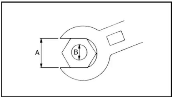
A: Distance across flats
B: Outside thread diameter
EC230000
DEFINITION OF UNITS
| Unit | Read | Definition | Measure |
| mmcm | milimetercentimeter | 10^-3 meter 10^-2 meter | LengthLength |
| kg | kilogram | 10^3 gram | Weight |
| N | Newton | 1kg × m/sec^2 | Force |
| Nm m•kg | Newton meterMeter kilogram | N × mm × kg | TorqueTorque |
| Pa | Pascal | N/m^2 | Pressure |
| N/mm | Newton per millimeter N/mm | Spring rate | |
| L cm3 | LiterCubic centimeter | —— | Volume or capacityVolume or capacity |
| r/min | Revolution per minute | —— | Engine speed |
CARACTERISTIQUES
CARACTERISTIQUES GENERALES
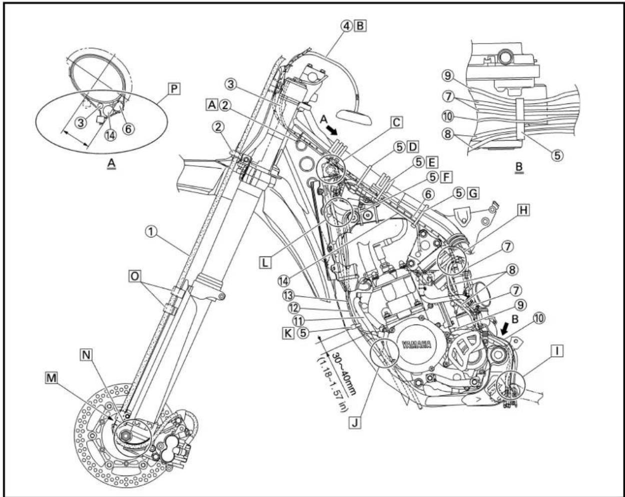
①Brake hose
②Cable guide
③"ENGINE STOP" button lead
④Fuel tank breather hose
⑤Clamp
⑥Throttle cable
⑦Air vent hose (right)
⑧Air vent hose (left)
⑨Transmission oil breather hose
⑩Overflow hose
⑪YPVS breather hose
⑫Radiator breather hose
⑬CDI magneto lead
⑭Wireharness
A Pass the throttle cable and "ENGINE STOP" button lead into the cable guide. Align with the cable guide the front end of the tape on the throttle cable.
B Pass the fuel tank breather hose between the handlebar and tension bar, then insert its end into the hole of the number plate.
C Pass the throttle cable and "ENGINE STOP" button lead over the radiator hose.
D Clamp the throttle cable, "ENGINE STOP" button lead and wireharness to the main pipe. With the clamp ends downward, tighten the throttle cable to the extent that it moves smoothly.
Clamp the "ENGINE STOP" button lead (where there is no protector), wireharness and throttle cable all together to the main pipe with the clamp ends downward.
F Clamp the CDI magneto lead on the upper part of the frame gusset at its protecting tube.
G Clamp the throttle cable and wireharness to the main pipe. With the clamp ends downward, tighten the throttle cable to the extent that it moves smoothly.
H Pass the air vent hose at the rear of the throttle cable.
☐ Pass the transmission oil breather hose, air vent hoses and overflow hose between the frame and connecting rod.
☐ Pass the radiator breather hose and YPVS breather hose outside the engine bracket and inside the down tube. Then pass the radiator breather hose inside the YPVS breather hose.
K Clamp the radiator breather hose and CDI magneto lead on the rear of the down-tube.

SCHEMA DE CHEMINEMENT DES CABLES
①Tuyau de frein
②Guide de câble
☐ Pass the radiater breather hose and CDI magneto lead between the frame and radiator.
M Align the top of the brake hose neck with the brake hose holder bottom.
N Pass the brake hose in front of the axle boss, then fit it into the hose groove so that the brake hose does not contact the nut (wheel axle).
☐ Fit the brake hose into the guide on the protector.
P Position each lead at the lower left of the main tube (frame) and put the clamp ends within the area as shown by the arrow.
SCHEMA DE CHEMINEMENT DES CABLES KABELFÜHRUNGSÜBERSICHTPLAN DIAGRAMMA DEL PASSAGGIO DEI CAVI
SPEC

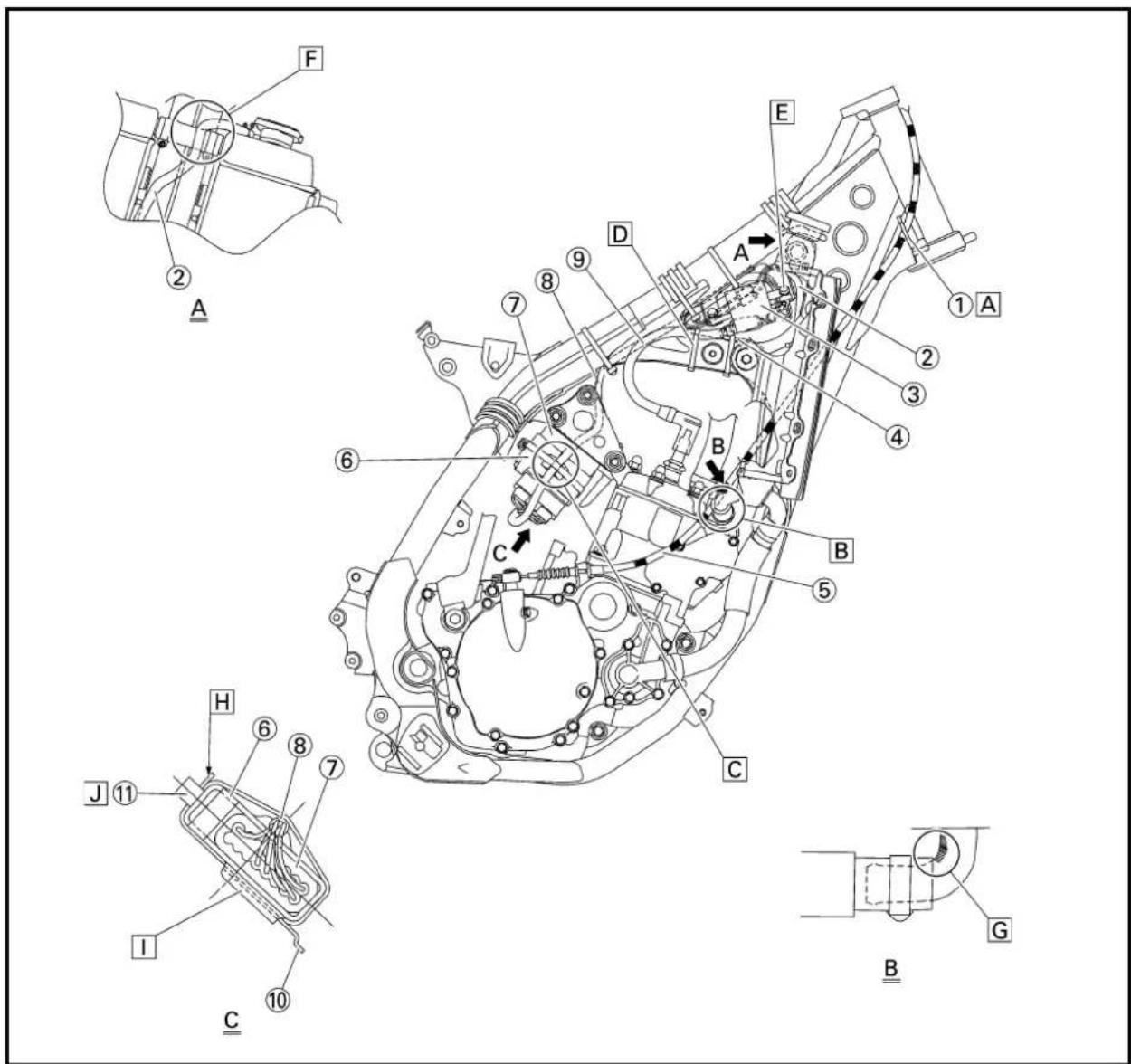
①Cable guide
②Radiator breather hose
③Ignition coil
④CDI magneto lead
⑤Clutch cable
⑥CDI unit band
⑦CDI unit
⑧Wireharness
⑨High tension cord
⑩CDI unit bracket
⑪Clamp
A Pass the cluch cable into the cable guide.
B Pass the clutch cable over the radiator hose.
C Pass the wireharness between the convexites of the CDI unit band.
D Clamp the high tension cord on the upper part of the frame gusset at its protecting tube.
E Pass the ground lead between the ignition coil and bracket and fasten it together with the ignition coil. Make sure that the ground lead does not contact the ignition coil and bracket.
F Pass the radiator breather hose at the rear of the radiator hose and in front of the ignition coil bracket.
G Push in the radiator hose until its end lightly touches the radiator pipe.
H Cut the clamp end to be flush with CDI unit side.
☐ Fit the CDI unit band over the CDI unit bracket till it stops.
☐ Clamp the wireharness on the CDI unit with the clamp ends upward.
SCHEMA DE CHEMINEMENT DES CABLES KABELFÜHRUNGSÜBERSICHTPLAN DIAGRAMMA DEL PASSAGGIO DEI CAVI
①Guide de câble
①Master cylinder
②Brake hose holder
③Brake hose
A Install the brake hose so that its pipe portion directs as shown and lightly touches the projection on the caliper.
B Pass the brake hose into the brake hose holders.
C If the brake hose contacts the spring (rear shock absorber), correct its twist.
☐ Install the brake hose so that its pipe portion directs as shown and lightly touches the projection on the master cylinder.

SCHEMA DE CHEMINEMENT DES CABLES KABELFÜHRUNGSÜBERSICHTPLAN DIAGRAMMA DEL PASSAGGIO DEI CAVI
SPEC

A Install the brake hose so that its pipe portion directs as shown and lightly touches the projection on the master cylinder.
B Pass the "ENGINE STOP" button lead in the middle of the clutch holder.
C Pass the clutch cable in front of the throttle cable.
D Clamp the "ENGINE STOP" button lead to the handlebar to 3 clicks.
E Pass the brake hose in front of the number plate and through the cable guide.
F Cross the clutch cable and throttle cable over the number plate boss.

SCHEMA DE CHEMINEMENT DES CABLES KABELFÜHRUNGSÜBERSICHTPLAN DIAGRAMMA DEL PASSAGGIO DEI CAVI

①Tuyau de frein
②Maître-cylindre
The following schedule is intended as a general guide to maintenance and lubrication. Bear in mind that such factors as weather, terrain, geographical location, and individual usage will alter the required maintenance and lubrication intervals. If you are a doubt as to what intervals to follow in maintaining and lubricating your machine, consult your Yamaha dealer.
| Item Remarks | After break-in | Every race | Every third | Every fifth | As required | |
| PISTONInspect and cleanReplace ● ● | ● | ● | Inspect crackInspect carbon deposits and eliminate them | |||
| PISTON RINGInspect ● ●Replace ● ● | Check ring end gap | |||||
| PISTON PIN, SMALL END BEARINGInspect ●Replace ● | ||||||
| CYLINDER HEADInspect and clean ● ●Retighten ● ● | Inspect carbon deposits and eliminate themCheck gasket | |||||
| CYLINDERInspect and clean ● ●Replace ● | Inspect score marksInspect wear | |||||
| YPVSInspect and clean ● ● | Inspect carbon deposits and eliminate them | |||||
| CLUTCHInspect and adjust ● ●Replace ● | Inspect housing, friction plate, clutch plate and spring | |||||
| TRANSMISSIONReplace oil ● ●Inspect ●Replace bearing ● | Yamalube 4 (10W-30) or SAE 10W-30 SE motor oil | |||||
| SHIFT FORK, SHIFT CAM, GUIDE BARInspect ● | Inspect wear | |||||
| ROTOR NUTRetighten ● ● | ||||||
| MUFFLERInspect ● ●Clean ● | ||||||
| CRANKInspect and clean ● ● | ||||||
| CARBURETORInspect, adjust and clean | ● | ● | ||||
| SPARK PLUGInspect and clean ● ●Replace ● | ||||||
| DRIVE CHAINLubricate, slack, alignmentReplace ● | ● | ● | Use chain lubeChain slack: 40~50 mm(1.6~2.0 in) | |||
| COOLING SYSTEMCheck coolant level and leakage ●Check radiator cap operation ●Replace coolant ●Every two yearsInspect hoses ● | ● | |||||
| OUTSIDE NUTS AND BOLTS Refer to “STARTINGRetighten ● ● AND BREAK-IN” section | in the CHAPTER 1. | |||||
| AIR FILTERClean and lubricate ● ●Replace ●equivalent oil | Use foam air-filter oil or | |||||
| FRAMEClean and inspect ● ● | ||||||
| FUEL TANK, COCKClean and inspect ● ● | ||||||
| BRAKESAdjust lever position and pedal height ●Lubricate pivot point ● ●Check brake disc surface ● ●Check fluid level and leakageRetighten brake disc bolts, caliper bolts,master cylinder bolts and union boltsReplace padsReplace brake fluid | ●●●● | ●●● | ●●●Every one year | |||
| FRONT FORKSInspect and adjustReplace oilReplace oil seal | ●●● | ● | ● | ● | Suspension oil “01” | |
| FRONT FORK OIL SEAL AND DUST SEALClean and lube | ● | ● | Lithium base grease | |||
| REAR SHOCK ABSORBERInspect and adjustLubeRetighten ● ● | ● | ● | ● | (After rain ride)● | Molybdenum disulfide grease | |
| CHAIN GUARD AND ROLLERSInspect | ● | ● | ||||
| SWINGARMInspect, lube and retighten | ● | ● | Molybdenum disulfide grease | |||
| RELAY ARM, CONNECTING RODInspect, lube and retighten | ● | ● | Molybdenum disulfide grease | |||
| STEERING HEADInspect free play and retightenClean and lube ● Lithium base greaseReplace bearing | ● | ● | ● | |||
| TIRE, WHEELSInspect air pressure, wheel run-out,tire wear and spoke loosenessRetighten sprocket boltInspect bearingsReplace bearingsLubricate | ●●● | ●●● | ●● | ● | Lithium base grease | |
| THROTTLE, CONTROL CABLECheck routing and connectionLubricate | ●● | ●● | Yamaha cable lube orSAE 10W-30 motor oil | |||

MEMO
VERIFICATION ET REGLAGES COURANTS PROGRAMME D'ENTRETIEN
Before riding for break-in operation, practice or a race, make sure the machine is in good operating condition.
Before using this machine, check the following points.
EC321000
GENERAL INSPECTION AND MAINTENANCE
| Item Routine Page | ||
| Coolant Check that coolant is filled up to the radiator filler cap.Check the cooling system for leakage. | P3-5~9 | |
| Fuel Check that a fresh mixture of oil and gasoline is filled in the fuel tank. Check the fuel line for leakage. | P1-12 | |
| Transmission oil Check that the oil level is correct. Check the crankcase for leakage. | P3-12~14 | |
| Gear shifter and clutch Check that gears can be shifted correctly in order and that the clutch operates smoothly. | P3-9 | |
| Throttle grip/Housing Check that the throttle grip operation and free play are correctly adjusted. Lubricate the throttle grip and P3-10~11 housing, if necessary. | ||
| Brakes Check the play of front brake and effect of front and rear brake. | P3-17~23 | |
| Chain Check chain slack and alignment. Check that the chain is lubricated properly. | P3-24~26 | |
| Wheels Check for excessive wear and tire pressure. Check for loose spokes and have no excessive play. | P3-34~35 | |
| Steering Check that the handlebar can be turned smoothly and have no excessive play. | P3-35~36 | |
| Front forks and Check that they operate smoothly and there is no oil rear shock absorber leakage. | P3-26~33 | |
| Cables (wires) Check that the clutch and throttle cables move smoothly. Check that they are not caught when the handlebars are turned or when the front forks travel up and down. | — | |
| Muffler | Check that the muffler is tightly mounted and has no cracks. | P3-15~16 |
| Sprocket | Check that the driven sprocket tightening bolt is not loose. | P3-24 |
| Lubrication | Check for smooth operation. Lubricate if necessary. | P3-37 |
| Bolts and nuts | Check the chassis and engine for loose bolts and nuts. P1-16 | |
| Lead connectors | Check that the CDI magneto, CDI unit, and ignition coil are connected tightly. | P1-6 |
| Settings | Is the machine set suitably for the condition of the racing course and weather or by taking into account the results of test runs before racing? Are inspection and maintenance completely done? | P7-1~25 |
INSPECTION ET ENTRETIEN AVANT UTILISATION
EC350000
ENGINE
EC351011
COOLANT LEVEL INSPECTION
WARNING
Do not remove the radiator cap ①,⑪ drain bolt and hoses when the engine and radiator are hot. Scalding hot fluid and steam may be blown out under pressure, which could cause serious injury.
When the engine has cooled, place a thick towel over the radiator cap, slowly rotate the cap counterclockwise to the detent. This procedure allows any residual pressure to escape. When the hissing sound has stopped, press down on the cap while turning counterclockwise and remove it.
CAUTION:
Hard water or salt water is harmful to the engine parts. You may use distilled water, if you can't get soft water.
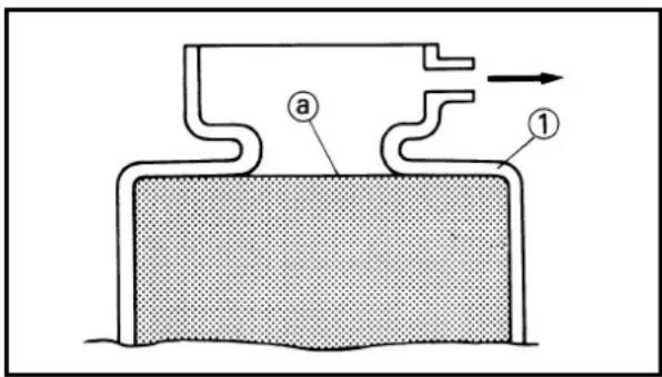
- Place the machine on a level place, and hold it in an upright position.
- Remove:
- Radiator cap
- Check:
- Coolant level ⓐ
Coolant level low → Add coolant.
①Radiator
EC353011
COOLANT REPLACEMENT
WARNING
Do not remove the radiator cap when the engine is hot.
MOTEUR
VERIFICATION DU NIVEAU DU LIQUIDE DE REFROIDISSEMENT
AVERTISSEMENT
Take care so that coolant does not splash on painted surfaces. If it splashes, wash it away with water.
natural_image
Mechanical assembly diagram showing a linkage mechanism with bolts and a labeled component (no text or symbols present)-
Place a container under the engine.
-
Remove:
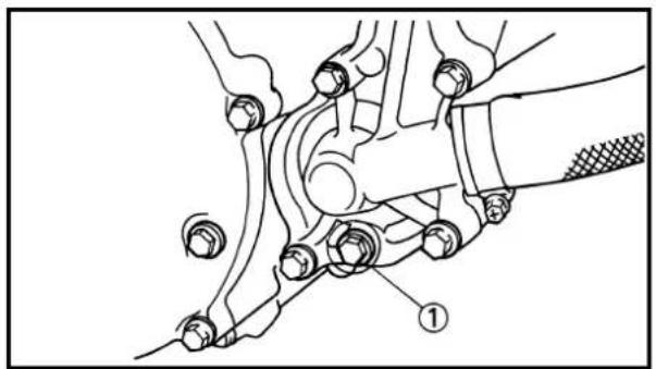
- Coolant drain bolt ①
- Remove:
•Radiator cap
Drain the coolant completely.
- Clean:
•Cooling system
Thoroughly flush the cooling system with clean tap water.
- Install:
• Copper washer
New
•Coolant drain bolt
10 Nm (1.0 m•kg, 7.2 ft•lb)

- Fill:
•Radiator
•Engine
To specified level.

Recommended coolant: High quality ethylene glycol anti-freeze containing anti-corrosion for aluminum engine
Coolant ① and water
(soft water) ② mixing ratio: 50%/50%
Coolant capacity: 0.95 L (0.84 Imp qt, 1.00 US qt)
ATTENTION:
- Do not mix more than one type of ethylene glycol antifreeze containing corrosion inhibitors for aluminum engine.
- Do not use water containing impurities or oil.
Handling notes of coolant:
The coolant is harmful so it should be handled with special care.
WARNING
- When coolant splashes to your eye.
Thoroughly wash your eye with water and see your doctor. - When coolant splashes to your clothes.
Quickly wash it away with water and then with soap. - When coolant is swallowed.
Quickly make him vomit and take him to a doctor.
7. Install:
- Radiator cap Start the engine and warm it up for a several minutes.
8. Check:
- Coolant level Coolant level low → Add coolant.

EC355000
RADIATOR CAP INSPECTION
1. Inspect:
- Seal (radiator cap) ①
- Valve and valve seat ②
Crack/Damage →Replace.
Exist fur deposits ③→Clean or replace.
ATTENTION:
EC356002
RADIATOR CAP OPENING PRESSURE INSPECTION
- Attach:
•Radiator cap tester ①and adapter ②

Radiator cap tester: YU-24460-01/90890-01325
Adapter: YU-33984/90890-01352
NOTE:
Apply water on the radiator cap seal.
③Radiator cap
- Apply the specified pressure.

Radiator cap opening pressure: 95\~125 kPa (0.95\~1.25 kg/cm², 13.5\~17.8 psi)
- Inspect:
•Pressure
Impossible to maintain the specified pressure for 10 seconds →Replace.

EC357003
COOLING SYSTEM INSPECTION
- Inspect:
•Coolant level
- Attach:
•Radiator cap tester ①and adapter ②

Radiator cap tester: YU-24460-01/90890-01325
Adapter: YU-33984/90890-01352
- Apply the specified pressure.

Standard pressure: 180 kPa (1.8 kg/cm ^2 , 25.6 psi)
VERIFICATION DE LA PRESSION D'OUVERTURE DU BOUCHON DU RADIATEUR
- Attacher:
- Do not apply pressure more than specified pressure.
- Radiator should be filled fully.


4. Inspect:
-Pressure
Impossible to maintain the specified pressure for 10 seconds → Repair.
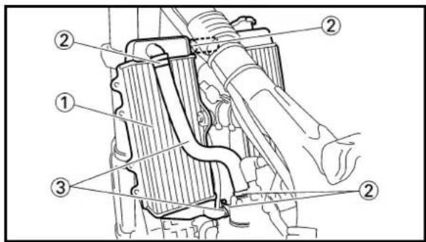
•Radiator ①
•Radiator hose joint ②
Coolant leakage → Repair or replace.
- Radiator hose ③
Swelling →Replace.
EC359020
CLUTCH ADJUSTMENT
1. Check:
- Clutch lever free play ⓐ
Out of specification →Adjust.

Clutch lever free play a:8 8\~13 mm (0.31\~0.51 in)
2. Adjust:
- Clutch lever free play
Clutch lever free play adjustment steps:
- Loosen the locknut ①.
- Turn the adjuster ②until free play @is within the specified limits.
- Tighten the locknut.
NOTE:
- Make minute adjustment on the lever side using the adjuster ③.
• After adjustment, check proper operation of clutch lever.
N.B.:
natural_image
Technical line drawing of a mechanical component with a shaft and housing, showing motion direction (no text or symbols)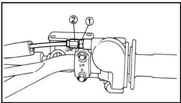
EC35A001
THROTTLE CABLE ADJUSTMENT
1. Check:
- Throttle grip free play ⓐ Out of specification→Adjust.

Throttle grip free play ⓐ3\~5 mm (0.12\~0.20 in)
2. Adjust:
•Throttle grip free play
Throttle grip free play adjustment steps:
- Loosen the locknut ①.
- Turn the adjuster ② until the specified free play is obtained.
- Tighten the locknut.
NOTE:
Before adjusting the throttle cable free play, the engine idle speed should be adjusted.
WARNING
After adjusting, turn the handlebar to right and left and make sure that the engine idling does not run faster.

EC35S002
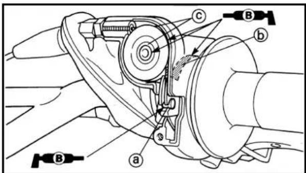
THROTTLE LUBRICATION
1. Remove:
- Cap cover ①
•Throttle cable cap ②
2. Apply:
- Lithium soap base grease On the throttle cable end ⓐ, tube guide cable winding portion Ⓐ and roller sliding surface Ⓒ.
REGLAGE DU CABLE
D'ACCELERATION
- Contrôler:
Proper air filter maintenance is the biggest key to preventing premature engine wear and damage.
CAUTION:
Never run the engine without the air filter element in place; this would allow dirt and dust to enter the engine and cause rapid wear and possible engine damage.

natural_image
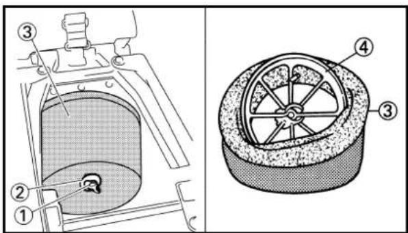
Illustration showing three steps of cleaning a container with a tool, no text or symbols present1. Remove:
- Seat
- Fitting bolt ①
- Washer ②
•Air filter element ③
-Filter guide ④
2. Clean:
•Air filter element
Clean them with solvent.
NOTE:
After cleaning, remove the remaining solvent by squeezing the element.
CAUTION:
Do not twist the element when squeezing the element.
3. Monter:

- Inspect:
•Air filter element
Damage →Replace.
- Apply:
- Foam-air-filter oil or equivalent oil
To the element.
NOTE:
Squeeze out the excess oil. Element should be wet but not dripping.
- Install:
-Filter guide ①
NOTE:
Align the projection ⓐ on filter guide with the hole ⓑ in air filter element.
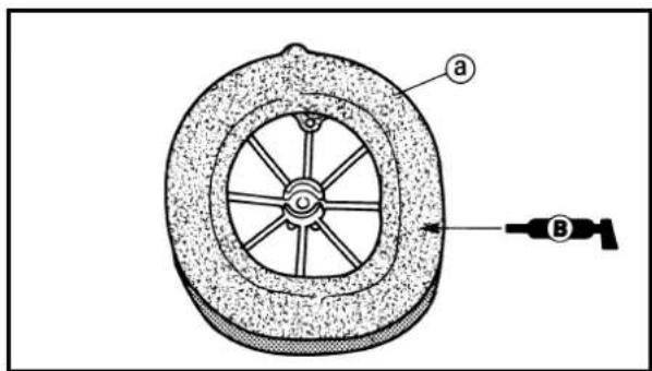
- Apply:
• Lithium soap base grease
On the matching surface ⓐ on air filter element.
- Install:
•Air filter element ①
•Washer
- Fitting bolt
2 Nm (0.2 m•kg, 1.4 ft•lb)
NOTE:
Align the projection ⓐ on filter guide with the hole ⓑ in air filter case.
EC35H002
TRANSMISSION OIL LEVEL CHECK
- Start the engine, warm it up for several minutes and wait for five minutes.
- Place the machine on a level place and hold it up on upright position by placing the suitable stand under the engine.
CONTROLE DU NIVEAU DE L'HUILE DE BOITE DE VITESSES PRÜFUNG DES GETRIEBEÖLSTANDES CONTROLLO DEL LIVELLO DELL'OLIO DELLA TRASMISSIONE

- Examiner:
natural_image
Mechanical assembly diagram showing a linkage mechanism with bolts and a numbered component (no text or symbols present)3. Check:
•Transmission oil level
Transmission oil level checking steps:
- Remove the oil check bolt ①.
- Inspect the oil level.
NOTE:
Be sure the machine is positioned straight up when inspecting the oil level.
WARNING
Never attempt to remove the oil check bolt just after high speed operation. The heated oil could spout out, causing danger. Wait until the oil cools down.
Oil flows out → Oil level is correct.
Oil does not flow out → Oil level is low.
Add transmission oil until oil flows out.

Recommended oil:
Yamalube 4 (10W-30) or SAE
10W-30 type SE motor oil
- Inspect the gasket (oil check bolt), replace if damaged.
- Tighten the oil check bolt.

Oil check bolt:
10 Nm (1.0 m•kg, 7.2 ft•lb)
EC35K002
TRANSMISSION OIL REPLACEMENT
- Start the engine and warm it up for several minutes and wait for five minute.
- Place the machine on a level place and hold it on upright position by placing the suitable stand under the engine.
- Place a suitable container under the engine.
CHANGEMENT DE L'HUILE DE BOITE DE VITESSES ERNEUERUNG DES GETRIEBEÖLS SOSTITUZIONE DELL'OLIO DELLA TRASMISSIONE
INSP ADJ
[NO TEXT]
3. Contrôler:
natural_image
Line drawing of a mechanical component with no visible text or symbols
natural_image
Mechanical assembly diagram showing a hand operating a valve with a numbered component (no text or symbols present)4. Remove:
- Oil drain bolt ①
- Oil filler cap ②
Drain the transmission oil.
5. Install:
•Aluminum washer
- Oil drain bolt ①
New
20 Nm (2.0 m•kg, 14 ft•lb)
6. Fill:
- Transmission oil

Recommended oil:
Yamalube 4 (10W-30) or SAE
10W-30 type SE motor oil
Oil capacity
(periodic oil change):
0.65 L (0.57 Imp qt, 0.69 US qt)
7. Check:
- Oil leakage
8. Check:
•Transmission oil level
9. Install:
- Oil filler cap ②

natural_image
Technical line drawing of mechanical components with no visible text or symbolsEC35L002
PILOT AIR SCREW ADJUSTMENT
1. Adjust:
•Pilot air screw ①
Adjustment steps:
- Screw in the pilot air screw until it is lightly seated.
- Back out by the specified number of turns.

Pilot air screw:
2 turns out
*1-1/2 turns out
*For EUROPE
4. Déposer:
EC35M010
IDLE SPEED ADJUSTMENT
- Start the engine and thoroughly warm it up.
- Adjust:
- Idle speed
Adjustment steps:
- Loosen the locknut ①.
- Turn the throttle stop screw ② until the engine runs at the lowest possible speed.
- Tighten the locknut.
To increase idle speed →Turn the throttle stop screw ②in.
To decrease idle speed →Turn the throttle stop screw ②③ out.

EC35P030
MUFFLER INSPECTION
- Inspect:
•O-ring ①
Damage →Replace.
NOTE:
Install the O-rings with their depressed @facing outward.

EC35R050
SILENCER FIBER REPLACEMENT
-
Remove:
-
Side cover (right)
•Bolt (silencer) ① - Silencer ②
- Bolt (fiber) ③
- Remove:
•Inner pipe ①
- Replace:
•Fiber ②
- Install:
- Inner pipe
NOTE:
Fully apply Quick gasket ^® (Yamaha bond No. 1215) or equivalent as shown.

Quick gasket®:
ACC-QUICK-GS-KT
Yamaha bond No. 1215:
90890-85505

- Install:
- Bolt (fiber) ①
10 Nm (1.0 m·kg, 7.2 ft·lb)
- Silencer ②
- Bolt [silencer (front)] ③
12 Nm (1.2 m•kg, 8.7 ft•lb)
- Bolt [silencer (rear)] ④
11 Nm (1.1 m•kg, 8.0 ft•lb)
- Side cover (right)
7 Nm (0.7 m•kg, 5.1 ft•lb)
CHANGEMENT DE FIBRE DU SILENCIEUX ERNEURUNG DES SCHALLDÄMPFER-FASEREINSATZES SOSTITUZIONE DELLA FIBRA DEL SILENZIATORE
INSP ADJ

- Déposer:
Bleed the brake system if:
• The system has been disassembled.
- A brake hose has been loosened or removed.
•The brake fluid is very low.
•The brake operation is faulty.
A dangerous loss of braking performance may occur if the brake system is not properly bleed.
-
Remove:
-
Master cylinder cap
•Diaphragm
•Protector (rear brake) -
Bleed:
- Brake fluid
A Front
B Rear
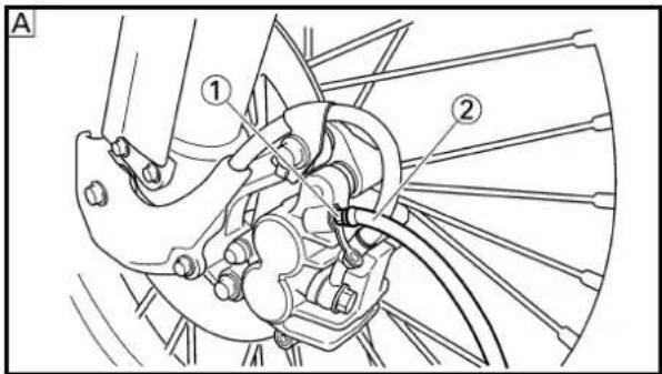

Air bleeding steps:
a. Add proper brake fluid to the reservoir.
b. Install the diaphragm. Be careful not to spill any fluid or allow the reservoir to overflow.
c. Connect the clear plastic tube ②tightly to the caliper bleed screw ①.
d. Place the other end of the tube into a container.
e. Slowly apply the brake lever or pedal several times.
f. Pull the lever in or push down on the pedal. Hold the lever or pedal in position.
g. Loosen the bleed screw and allow the lever or pedal to travel towards its limit.
h. Tighten the bleed screw when the lever or pedal limit has been reached; then release the lever or pedal.

Bleed screw:
6 Nm (0.6 m•kg, 4.3 ft•lb)
i. Repeat steps (e) to (h) until of the air bubbles have been removed from the system.
PARTIE CYCLE/PURGE DE L'AIR DU SYSTEME DE FREINAGE FAHRGESTELL/ENTLÜFTUNG DER BREMSANLAGE TELAIO/SPURGO DELL'ARIA DALL'IMPIANTO FRENANTE
INSP ADJ

PARTIE CYCLE
PURGE DE L'AIR DU SYSTEME DE FREINAGE
!AVERTISSEMENT
If bleeding is difficult, it may be necessary to let the brake fluid system stabilize for a few hours. Repeat the bleeding procedure when the tiny bubbles in the system have disappeared.
j. Add brake fluid to the level line on the reservoir.
WARNING
Check the operation of the brake after bleeding the brake system.
3. Install:
•Protector (rear brake)
•Diaphragm
- Master cylinder cap
EC362041

| Brake lever position a | |
| Standard position Extent of adjustment | |
| 95 mm (3.74 in) | 76 ~ 97 mm(2.99 ~ 3.82 in) |
- Remove:
- Lever cover
- Adjust:
- Brake lever position
Brake lever position adjustment steps:
- Loosen the locknut ①.
- Turn the adjusting bolt ② until the lever position a is within specified position.
- Tighten the locknut.
| Locknut:5 Nm (0.5 m•kg, 3.6 ft•lb) |
CAUTION:
Be sure to tighten the locknut, as it will cause poor brake performance.
- Install:
- Lever cover
N.B.:
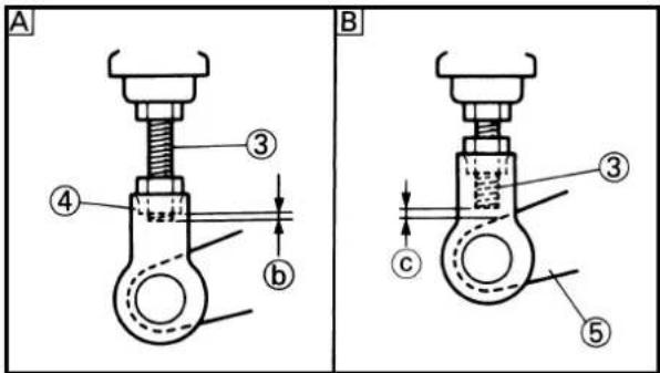
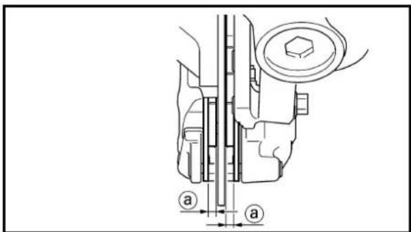
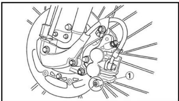
EC364004
The brake pedal height is the vertical distance from the inside top end of the footrest.
- Adjust:
- Brake pedal height
Pedal height adjustment steps:
- Loosen the locknut ①.
- Turn the adjusting nut ② until the pedal height ④ is within specified height.
- Tighten the locknut.
WARNING
- Adjust the pedal height between the maximum A and the minimum B as shown. (In this adjustment the bolt ③③ end b should protrude out of the threaded portion ④ but not be less than 2 mm (0.08 in) C away from the brake pedal ⑤)
• After the pedal height adjustment, make sure that the rear brake does not drag.
EC365080
FRONT BRAKE PAD INSPECTION AND REPLACEMENT
- Inspect:
- Brake pad thickness ⓐ Out of specification →Replace as a set.
| Brake pad thickness a:8 | ||
| Standard | ||
| 4.4 mm (0.17 in) | 1.0 mm (0.04 in) | |
- Replace:
-Brake pad
Brake pad replacement steps:
- Remove the pad pin plug ①.
REGLAGE DU FREIN ARRIERE
- Contôler:
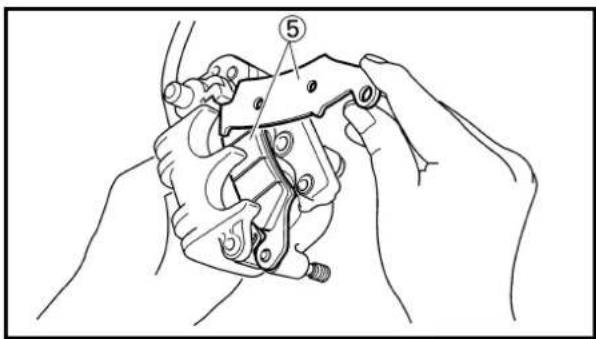
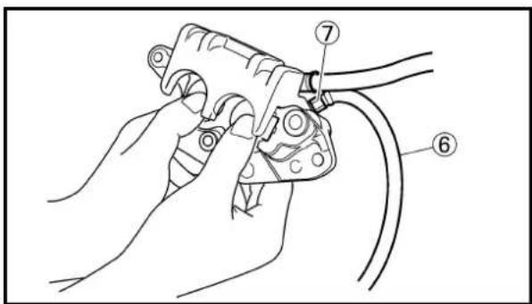


- Loosen the pad pin ②.
- Remove the brake hose holder ③and caliper ④from the front fork.
- Remove the pad pin and brake pads ⑤.
- Connect the transparent hose ⑥ to the bleed screw ⑦ and place the suitable container under its end.
- Loosen the bleed screw and push the caliper piston in.
CAUTION:
Do not reuse the drained brake fluid.
• Tighten the bleed screw.

Bleed screw:
6 Nm (0.6 m•kg, 4.3 ft•b)
• Install the brake pads ⑧ and pad pin.
NOTE:
• Install the brake pads with their projections
Ⓐ into the caliper recesses ⓑ.
• Temporarily tighten the pad pin at this point.
• Install the brake hose holder ⑨ and caliper ⑩ and tighten the pad pin ⑪.
NOTE:
Fit the brake hose holder cut ©over the projection ⓐon the front fork and clamp the brake hose.

Bolt (caliper):
23 Nm (2.3 m•kg, 17 ft•lb)
Pad pin:
18 Nm (1.8 m•kg, 13 ft•lb)
VERIFICATION ET CHANGEMENT DE LA PLAQUETTE DE FREIN AVANT INSPEKTION UND ERNEUERUNG DES VORDERRAD-BREMSBELAGPLATTE ISPEZIONE E SOSTITUZIONE DELLE PASTIGLIE DEL FRENO ANTERIORE
INSP ADJ

•Install the pad pin plug ⑫.

Pad pin plug:
3 Nm (0.3 m•kg, 2.2 ft•lb)
3. Inspect:
- Brake fluid level
Refer to "BRAKE FLUID LEVEL
INSPECTION" section.
4. Check:
- Brake lever operation
A softly or spongy feeling → Bleed brake system.
Refer to "BRAKE SYSTEM AIR BLEEDING" section.


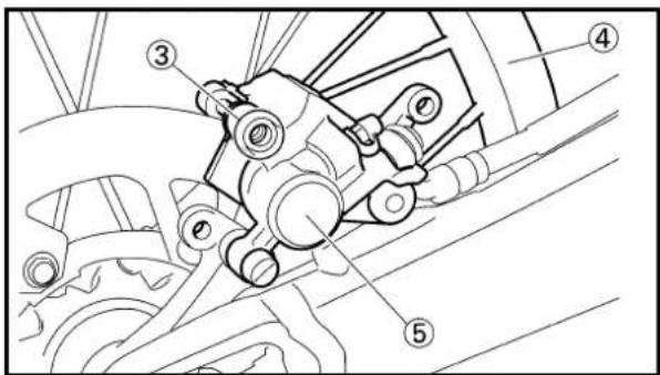
EC366060
REAR BRAKE PAD INSPECTION AND REPLACEMENT
1. Inspect:
- Brake pad thickness ⓐ
Out of specification →Replace as a set.
| Brake pad thickness a:8 | ||
| Standard | ||
| 6.4 mm (0.25 in) | 1.0 mm (0.04 in) | |
2. Replace:
-Brake pad
Brake pad replacement steps:
- Remove the protector ① and pad pin plug ②.
- Loosen the pad pin ③.
- Remove the rear wheel ④ and caliper ⑤. Refer to “FRONT WHEEL AND REAR WHEEL” section in the CHAPTER 5.
VERIFICATION ET CHANGEMENT DE LA PLAQUETTE DE FREINARRIERE INSPEKTION UND ERNEUERUNG DES HINTERRAD-BREMSBELAGPLATTE ISPEZIONE E SOSTITUZIONE DELLE PASTIGLIE DEL FRENO POSTERIORE
INSP ADJ


- Remove the pad pin ⑥ and brake pads ⑦.
- Connect the transparent hose ⑧ to the bleed screw ⑨ and place the suitable container under its end.
- Loosen the bleed screw and push the caliper piston in.
CAUTION:
Do not reuse the drained brake fluid.
• Tighten the bleed screw.

Bleed screw:
6 Nm (0.6 m•kg, 4.3 ft•lb)
• Install the brake pads ⑩ and pad pin ⑪.
NOTE:
• Install the brake pads with their projections
① into the caliper recesses ②.
• Temporarily tighten the pad pin at this point.
- Install the caliper ⑫ and rear wheel ⑬.
Refer to “FRONT WHEEL AND REAR WHEEL” section in the CHAPTER 5.
• Tighten the pad pin ⑭.

Pad pin:
18 Nm (1.8 m•kg, 13 ft•lb)
• Install the pad pin plug ⑮ and protector ⑯.

Pad pin plug:
3 Nm (0.3 m•kg, 2.2 ft•lb)
Bolt (protector):
7 Nm (0.7 m•kg, 5.1 ft•lb)
3. Inspect:
- Brake fluid level
Refer to "BRAKE FLUID LEVEL
INSPECTION" section.
4. Check:
- Brake pedal operation
A softly or spongy feeling → Bleed brake system.
Refer to "BRAKE SYSTEM AIR BLEEDING" section.
VERIFICATION ET CHANGEMENT DE LA PLAQUETTE DE FREINARRIERE INSPEKTION UND ERNEUERUNG DES HINTERRAD-BREMSBELAGPLATTE ISPEZIONE E SOSTITUZIONE DELLE PASTIGLIE DEL FRENO POSTERIORE
INSP ADJ

natural_image
Line drawing of three mechanical clips with a label pointing to the top-left corner (no text or symbols on the clips themselves)EC36b000
REAR BRAKE PAD INSULATOR INSPECTION
- Remove:
- Brake pad
Refer to "REAR BRAKE PAD INSPECTION AND REPLACEMENT" section.
- Inspect:
- Rear brake pad insulator ① Damage →Replace.

EC367001
- Place the master cylinder so that its top is in a horizontal position.
- Inspect:
- Brake fluid level
Fluid at lower level → Fill up.
aLower level
A Front
B Rear

Recommended brake fluid: DOT #4
WARNING
- Use only designated quality brake fluid to avoid poor brake performance.
- Refill with same type and brand of brake fluid; mixing fluids could result in poor brake performance.
- Be sure that water or other contaminants do not enter master cylinder when refilling.
- Clean up spilled fluid immediately to avoid erosion of painted surfaces or plastic parts.
VERIFICATION DE L'ISOLANT DE LA PLAQUETTE DE FREIN ARRIERE
1. Déposer:

natural_image
Line drawing of a hand using a tool to clean or brush over a container with granular material (no text or symbols)

EC368000
SPROCKETS INSPECTION
- Inspect:
•Sprocket teeth ⓐ
Excessive wear →Replace.
NOTE:
Replace the drive, driven sprockets and drive chain as a set.
EC369002
DRIVE CHAIN INSPECTION
-
Remove:
-
Master link clip
•Joint ①
-Drive chain ② -
Clean:
-Drive chain
Place it in kerosene, and brush off as much dirt as possible. Then remove the chain from the kerosene and dry the chain.
- Measure:
-Drive chain length (10 links) a
Out of specification→Replace.

Drive chain length (10 links):
Limit: 152.5 mm (6.004 in)
- Check:
-Drive chain stiffness a
Clean and oil the chain and hold as illustrated.
Stiff → Replace drive chain.
VERIFICATION DES PIGNONS
- Examiner:
- Dent de pignon ⓐ Usure excessif→Changer.
N.B.:
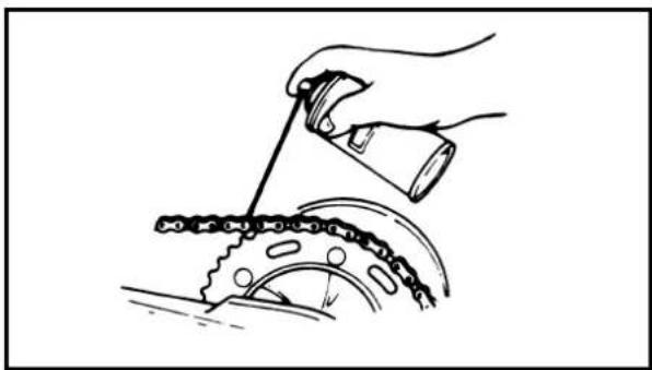
natural_image
Illustration of a hand using a tool to chain a gear, with motion lines indicating speed (no text or symbols)- Install:
-Drive chain ①
•Joint ②
- Master link clip ③
New
CAUTION:
Be sure to install the master link clip to the direction as shown.
aTurning direction
- Lubricate:
-Drive chain

Drive chain lubricant: SAE 10W-30 motor oil or suitable chain lubricants
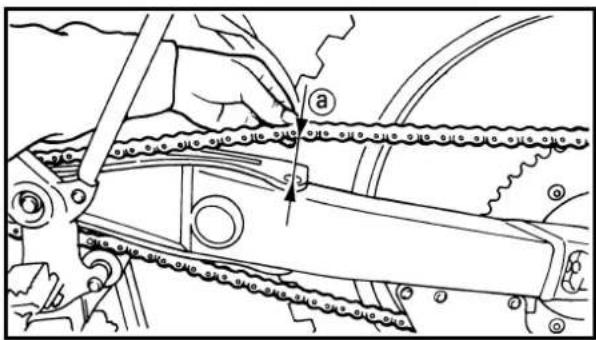
EC36A061
DRIVE CHAIN SLACK ADJUSTMENT
- Elevate the rear wheel by placing the suitable stand under the engine.
- Check:
-Drive chain slack ⓐ
Above the seal guard installation bolt.
Out of specification →Adjust

Drive chain slack: 40\~50 mm (1.6\~2.0 in)
NOTE:
Before checking and/or adjusting, rotate the rear wheel through several revolutions and check the slack several times to find the tightest point. Check and/or adjust chain slack with rear wheel in this "tight chain" position.
REGLAGE DE LA FLECHE DE CHAINE DE TRANSMISSION
3. Adjust:
-Drive chain slack
Drive chain slack adjustment steps:
- Loosen the axle nut ① and locknuts ②.
- Adjust chain slack by turning the adjusters ③.
To tighten →Turn adjuster ③counter-clockwise.
To loosen →Turn adjuster ③clockwise and push wheel forward.
- Turn each adjuster exactly the same amount to maintain correct axle alignment. (There are marks ⓐ on each side of chain puller alignment.)
NOTE:
Turn the adjuster so that the chain is in line with the sprocket, as viewed from the rear.
CAUTION:
Too small chain slack will overload the engine and other vital parts; keep the slack within the specified limits.
- Tighten the axle nut while pushing down the drive chain.

Axle nut: 125 Nm (12.5 m•kg, 90 ft•lb)
- Tighten the locknuts.

Locknut: 16 Nm (1.6 m•kg, 11 ft•lb)

natural_image
Mechanical diagram showing a bicycle's wheel and suspension mechanism with no text or symbolsEC36C000
FRONT FORK INSPECTION
1. Inspect:
- Front fork smooth action Operate the front brake and stroke the front fork. Unsmooth action/oil leakage →Repair or replace.
VERIFICATION DE LA FOURCHE AVANT INSPEKTION DER VORDERRADGABEL ISPEZIONE DELLA FORCELLA ANTERIORE
INSP ADJ

3. Régler:
natural_image
Technical line drawing of a mechanical clamp or bracket assembly (no text or symbols)


EC36D001
FRONT FORK OIL SEAL AND DUST SEAL CLEANING
- Remove:
•Protector
• Dust seal ①
NOTE:
Use a thin screw driver, and be careful not to damage the inner fork tube and dust seal.
-
Clean:
-
Dust seal ⓐ
- Oil seal ⓑ
NOTE:
- Clean the dust seal and oil seal after every run.
- Apply the lithium soap base grease on the inner tube.
EC36f000
FRONT FORK INTERNAL PRESSURE RELIEVING
NOTE:
If the front fork initial movement feels stiff during a run, relieve the front fork internal pressure.
- Elevate the front wheel by placing a suitable stand under the engine.
- Remove the air bleed screw ① and release the internal pressure from the front fork.
- Install:
• Air bleed screw
1 Nm (0.1 m•kg, 0.7 ft•lb)
EC36H002
FRONT FORK REBOUND DAMPING FORCE ADJUSTMENT
- Adjust:
- Rebound damping force By turning the adjuster ①.
Stiffer a→Increase the rebound damping force. (Turn the adjuster ①in.)
Softer ⑥Decrease the rebound damping force. (Turn the adjuster ①out.)
NETTOYAGE DE BAGUE
Extent of adjustment:
| Maximum | Minimum |
| Fully turned in position | 20 clicks out (from maximum position) |
• STANDARD POSITION:
This is the position which is back by the specific number of clicks from the fully turned-in position.

Standard position:
12 clicks out
*9 clicks out
*For EUROPE
CAUTION:
Do not force the adjuster past the minimum or maximum extent of adjustment. The adjuster may be damaged.
WARNING
Always adjust each front fork to the same setting. Uneven adjustment can cause poor handling and loss of stability.

EC36J001
FRONT FORK COMPRESSION DAMPING FORCE ADJUSTMENT
- Remove:
•Rubber cap
- Adjust:
- Compression damping force By turning the adjuster ①.
Stiffer ⓐ→Increase the compression damping force. (Turn the adjuster ①in.)
Softer ⑥>Decrease the compression damping force. (Turn the adjuster ① out.)

Etendue de réglage:
Maximum Minimum
| Extent of adjustment: | ||
| Maximum | Minimum | |
| Fully turned in position | 20 clicks out (from maximum position) | |
•STANDARD POSITION:
This is the position which is back by the specific number of clicks from the fully turned-in position.

*For EUROPE
CAUTION:
Do not force the adjuster past the minimum or maximum extent of adjustment. The adjuster may be damaged.
WARNING
Always adjust each front fork to the same setting. Uneven adjustment can cause poor handling and loss of stability.
- Install:
- Rubber cap
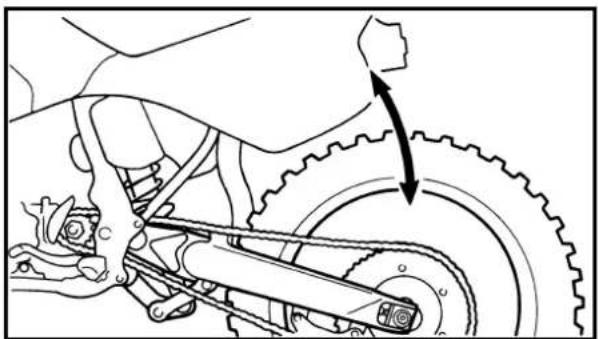
natural_image
Mechanical assembly diagram showing gear and chain components with an arrow indicating motion direction (no text or labels)EC36K000
REAR SHOCK ABSORBER INSPECTION
- Inspect:
•Swingarm smooth action
Abnormal noise/Unsmooth action →
Grease the pivoting points or repair the pivoting points.
Damage/Oil leakage →Replace.
VERIFICATION DE L'AMORTISSEUR ARRIERE INSPEKTION DES HINTERRAD-STOSSDÄMPFERS ISPEZIONE DELL'AMMORTIZZATORE POSTERIORE
INSP ADJ
[NO TEXT]
EC36M014
REAR SHOCK ABSORBER SPRING PRELOAD ADJUSTMENT
- Elevate the rear wheel by placing the suitable stand under the engine.
- Remove:
•Rear frame
- Loosen:
- Locknut ①
- Adjust:
- Spring preload
By turning the adjuster ②.
Stiffer → Increase the spring preload. (Turn the adjuster ② in.)
Softer → Decrease the spring pre-load. (Turn the adjuster ②③ out.)

natural_image
Technical line drawing of a mechanical spring assembly with dimension label (a), no text or symbols present| Spring length (installed) a:3 | ||
| Standard length | Extent of adjustment | |
| 251 mm (9.88 in)*262 mm (10.31 in) | 240.5~258.5 mm(9.47~10.18 in)*255.5~273.5 mm(10.06~10.77 in) | |
*For EUROPE
NOTE:
- Be sure to remove all dirt and mud from around the locknut and adjuster before adjustment.
- The length of the spring (installed) changes 1.5 mm (0.06 in) per turn of the adjuster.
CAUTION:
Never attempt to turn the adjuster beyond the maximum or minimum setting.
- Tighten:
- Locknut
- Install:
•Rear frame (upper)
32 Nm (3.2 m•kg, 23 ft•lb)
•Rear frame (lower)
29 Nm (2.9 m•kg, 21 ft•lb)
REGLAGE DE LA PRECON- TRAINTE DE RESSORT DE L'AMORTISSEUR ARRIERE
•Hintere Rahmen (Ober)
| 32 Nm (3,2 m•kg, 23 ft•lb) |
•Hintere Rahmen (Unter)
| 29 Nm (2,9 m•kg, 21 ft•lb) |
IC36M014
REGOLAZIONE DEL PRECARICO DELLA MOLLA DELL'AMMOR- TIZZATORE POSTERIORE
- Rebound damping force By turning the adjuster ①.

| Stiffer a s Increase the rebound damping force. (Turn the adjuster 1 in.) |
| Softer b b Decrease the rebound damping force. (Turn the adjuster 1 out.) |
| Extent of adjustment: | ||
| Maximum | Minimum | |
| Fully turned in position | 20 clicks out (from maximum position) | |

•STANDARD POSITION:
This is the position which is back by the specific number of clicks from the fully turned-in position. (Which align the punch mark ⓐ on the adjuster with the punch mark ⓑ on the bracket.)

Standard position: About 13 clicks out *About 11 clicks out
*For EUROPE
CAUTION:
Do not force the adjuster past the minimum or maximum extent of adjustment. The adjuster may be damaged.
REGLAGE DE LA FORCE D'AMORTISSEMENT DE REBOND DE L'AMORTISSEUR ARRIERE
- Régler:
-Force d'amortissement de rebond
EC36c000
REAR SHOCK ABSORBER LOW COMPRESSION DAMPING FORCE ADJUSTMENT
- Adjust:
- Low compression damping force By turning the adjuster ①.
Stiffer ①→Increase the low compression damping force. (Turn the adjuster ①in.)
Softer ⑥→Decrease the low compression damping force. (Turn the adjuster ①out.)
| Extent of adjustment: | ||
| Maximum | Minimum | |
| Fully turned in position | 20 clicks out (from maximum position) | |
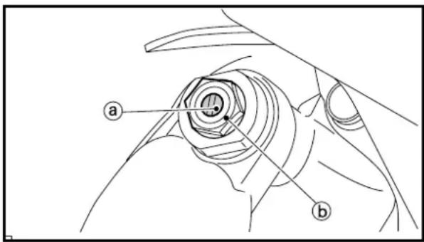
•STANDARD POSITION:
This is the position which is back by the specific number of clicks from the fully turned-in position. (Which align the punch mark ⓐ on the adjuster with the punch mark ⓑ on the high compression damping adjuster.)

Standard position: About 13 clicks out *About 11 clicks out
*For EUROPE
CAUTION:
Do not force the adjuster past the minimum or maximum extent of adjustment. The adjuster may be damaged.
REGLAGE DE LA FORCE D'AMORTISSEMENT DE COMPRESSION BASSE DE L'AMORTISSEUR ARRIERE
1. Régler:
EC36d000
REAR SHOCK ABSORBER HIGH COMPRESSION DAMPING FORCE ADJUSTMENT
- Adjust:
- High compression damping force By turning the adjuster ①.
Stiffer ①→Increase the high compression damping force. (Turn the adjuster ①in.)
Softer ⑥→Decrease the high compression damping force. (Turn the adjuster ①out.)
| Extent of adjustment: | ||
| Maximum | Minimum | |
| Fully turned in position | 2 turns out (from maximum position) | |
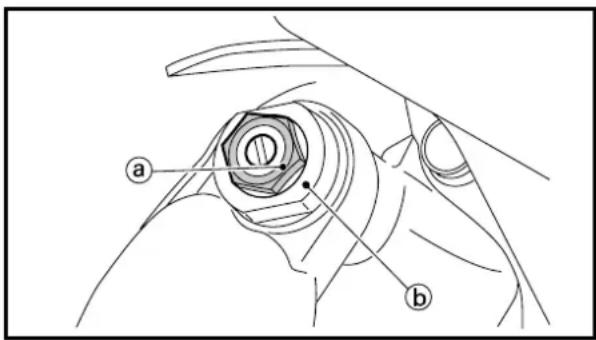
•STANDARD POSITION:
This is the position which is back by the specific number of turns from the fully turned-in position. (Which align the punch mark ⓐ on the adjuster with the punch mark ⓑ on the adjuster body.)

Standard position: About 1-1/8 turns out *About 1 turn out
*For EUROPE
CAUTION:
Do not force the adjuster past the minimum or maximum extent of adjustment. The adjuster may be damaged.
REGLAGE DE LA FORCE D'AMORTISSEMENT DE COMPRESSION ELEVEE DE L'AMORTISSEUR ARRIERE
- Régler:
natural_image
Illustration of hands holding a stopwatch with a magnifying glass, no text or symbols presentEC36Q001
TIRE PRESSURE CHECK
- Measure:
•Tire pressure
Out of specification →Adjust.

Standard tire pressure: 100 kPa (1.0 kgf/cm ^2 , 15 psi)
NOTE:
- Check the tire while it is cold.
- Loose bead stoppers allow the tire to slip off its position on the rim when the tire pressure is low.
- A tilted tire valve stem indicates that the tire slips off its position on the rim.
- If the tire valve stem is found tilted, the tire is considered to be slipping off its position. Correct the tire position.
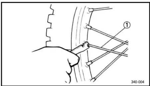
EC36S002
SPOKES INSPECTION AND TIGHTENING
- Inspect:
- Spokes ①
Bend/Damage →Replace.
Loose spoke → Retighten.
- Tighten:
•Spokes

3 Nm (0.3 m•kg, 2.2 ft•lb)
NOTE:
Be sure to retighten these spokes before and after break-in. After a practice or a race check spokes for looseness.

natural_image
Mechanical diagram showing a hand operating a gear and rotating a wheel, with no visible text or symbols.EC36T000
WHEEL INSPECTION
- Inspect:
- Wheel runout
Elevate the wheel and turn it.
Abnormal runout →Replace.
CONTROLE DE PRESSION DES PNEUS
- Mesurer:
natural_image
Mechanical diagram showing hands operating a wheel with rotating components and motion arrows (no text or symbols)
natural_image
Diagram of a hand using a tool to drive a wheel, showing rotational motion with no text or symbols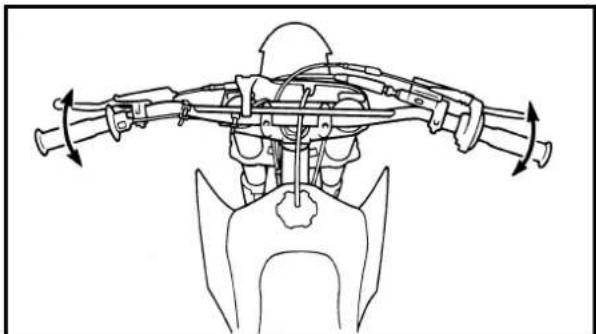
natural_image
Technical line drawing of a mechanical assembly with rotating components (no text or symbols)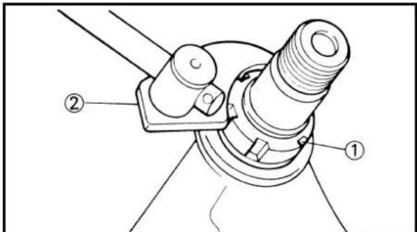

- Inspect:
- Bearing free play Exist play →Replace.
EC36U014
STEERING HEAD INSPECTION AND ADJUSTMENT
-
Elevate the front wheel by placing a suitable stand under the engine.
-
Check:
- Steering shaft Grasp the bottom of the forks and gently rock the fork assembly back and forth. Free play →Adjust steering head.
- Check:
- Steering smooth action Turn the handlebar lock to lock. Unsmooth action →Adjust steering ring nut.
- Adjust:
•Steering ring nut
Steering ring nut adjustment steps:
- Remove the number plate.
- Remove the handlebar and handle crown.
- Loosen the ring nut ① using the ring nut wrench ②.

Ring nut wrench: YU-33975/90890-01403
- Tighten the ring nut ③ using ring nut wrench ④.
NOTE:
Set the torque wrench to the ring nut wrench so that they form a right angle.
VERIFICATION ET REGLAGE DE LA TETE DE FOURCHE INSPEKTION UND EINSTELLUNG DES LENKERKOPFES ISPEZIONE E REGOLAZIONE DELLA TESTA DI STERZO
INSP ADJ

2. Examiner:
 | Ring nut wrench: YU-33975/90890-01403 |
 | Ring nut (initial tightening): 38 Nm (3.8 m•kg, 27ft•lb) |
| ·Loosen the ring nut one turn. ·Retighten the ring nut using the ring nut wrench. ▲WARNING Avoid over-tightening. | |
 | Ring nut (final tightening): 7 Nm (0.7 m•kg, 5.1 ft•lb) |
| ·Check the steering shaft by turning it lock to lock. If there is any binding, remove the steering shaft assembly and inspect the steering bearings. ·Install the handle crown ⑤, plain washer, steering shaft nut ⑥, handlebar ⑦, handle-bar holder ⑧ and number plate ⑨. NOTE: ·The upper handlebar holder should be installed with the punched mark a forward. ·Insert the end of fuel breather hose ⑩ into the hole of the number plate. | |
| CAUTION: | |
| First tighten the bolts on the front side of the handlebar holder, and then tighten the bolts on the rear side. | |
 | Steering shaft nut: 145 Nm (14.5 m•kg, 105 t•lb) Handlebar upper holder: 28 Nm (2.8 m•kg, 20 ft•lb) Pinch bolt (handle crown): 23 Nm (2.3 m•kg, 17 ft•lb) Number plate: 7 Nm (0.7 m•kg, 5.1 ft•lb) |
- Loosen the ring nut one turn.
- Retighten the ring nut using the ring nut wrench.
WARNING
Ring nut (final tightening): 7 Nm (0.7 m•kg, 5.1 ft•lb)
- Check the steering shaft by turning it lock to lock. If there is any binding, remove the steering shaft assembly and inspect the steering bearings.
• Install the handle crown ⑤, plain washer, steering shaft nut ⑥, handlebar ⑦, handlebar holder ⑧ and number plate ⑨.
NOTE:
- The upper handlebar holder should be installed with the punched mark @forward.
- Insert the end of fuel breather hose ⑩ into the hole of the number plate.
CAUTION:

To ensure smooth operation of all components, lubricate your machine during setup, after break-in, and after every race.
①All control cable
②Clutch lever pivot
③Shift pedal pivot
④Footrest pivot
⑤Throttle-to-handlebar contact
⑥Drive chain
⑦Throttle roller sliding surface
⑧Tube guide cable winding portion
⑨Throttle cable end
⑩Clutch cable end
A Use Yamaha cable lube or equivalent on these areas.
|B|Use SAE10W-30 motor oil or suitable chain lubricants.
C Lubricate the following areas with high quality, lightweight lithium-soap base grease.
CAUTION:
Wipe off any excess grease, and avoid getting grease on the brake discs.
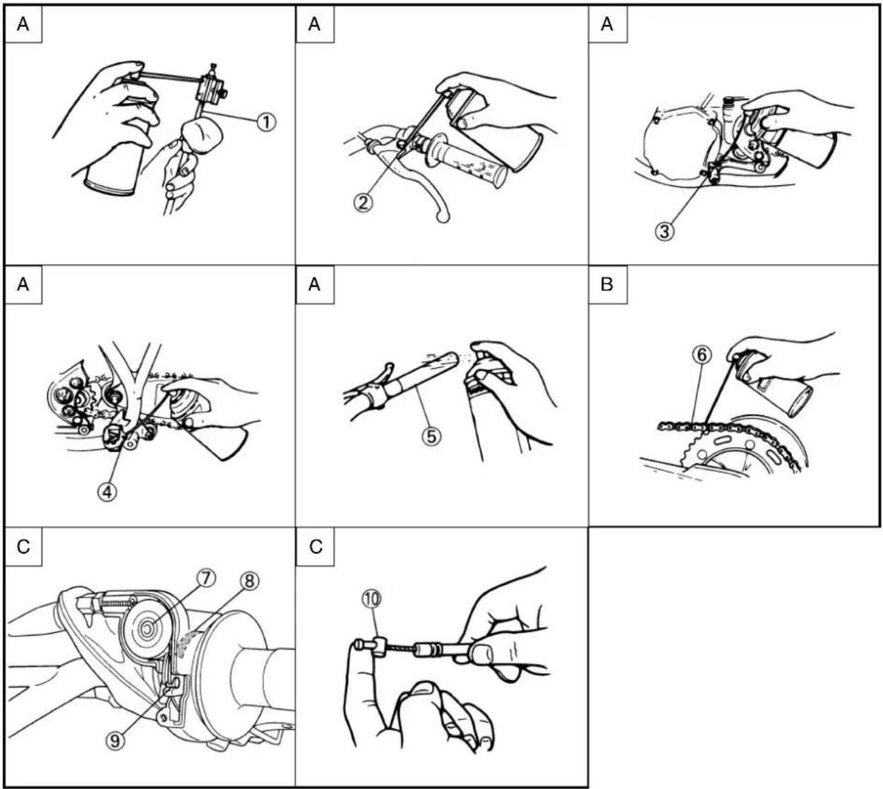
GRAISSAGE
EC370000
ELECTRICAL
EC371001
SPARK PLUG INSPECTION
- Remove:
•Spark plug
- Inspect:
- Electrode ①
Wear/Damage →Replace.
•Insulator color ②
Normal condition is a medium to light tan color.
Distinctly different color →Check the engine condition.
NOTE:
When the engine runs for many hours at low speeds, the spark plug insulator will become sooty, even if the engine and carburetor are in good operating condition.
- Measure:
•Plug gap ⓐ
Use a wire gauge or thickness gauge.
Out of specification → Regap.

Spark plug gap:
0.5\~0.6 mm (0.020\~0.024 in)
Standard spark plug:
BR9EG/NGK (resistance type)
- Clean the plug with a spark plug cleaner if necessary.

- Tighten:
- Spark plug

20 Nm (2.0 m•kg, 14 ft•lb)
NOTE:
- Before installing a spark plug, clean the gasket surface and plug surface.
- Finger-tighten ⓐthe spark plug before torquing to specification ⓑ.
PARTIE ELECTRIQUE/VERIFICATION DE LA BOUGIE ELEKTRISCHE EINRICHTUNGEN/INSPEKTION DER ZÜNDKERZE PARTE ELETTRICA/ ISPEZIONE DELLA CANDELA
INSP ADJ
[NO TEXT]
PARTIE ELECTRIQUE VERIFICATION DE LA BOUGIE
- Déposer:
•Bougie
- Examiner:
- Electrode ①
EC372012
IGNITION TIMING CHECK
- Remove:
- Fuel tank Refer to "SEAT, FUEL TANK AND SIDE COVERS" section in the CHAPTER 4.
- Spark plug - Crankcase cover (left)
- Attach:
- Dial gauge ① - Spark plug hole dial stand ②

Dial gauge: YU-3097/90890-01252 Spark plug hole dial stand: YU-1256

-
Rotate the magneto rotor ① until the piston reaches top dead center (TDC). When this happens, the needle on the dial gauge will stop and reverse directions even though the rotor is being turned in the same direction.
-
Set the dial gauge to zero at TDC.
-
From TDC, rotate the rotor clockwise until the dial gauge indicates that the piston is at a specified distance from TDC.

Ignition timing (B.T.D.C.): 0.52 mm (0.020 in)

- Check:
- Ignition timing Punch mark ⓐon rotor should be aligned with punch mark Ⓑon stator. Not aligned ->Adjust.
CONTROLE ET REGLAGE DE L'AVANCE A L'ALLUMAGE
1. Déposer:
7. Adjust:
- Ignition timing
Adjustment steps:
- Loosen the screws (stator) ①.
- Align the punch mark on the rotor with punch mark on the stator ② by moving the stator.
• Tighten the screws (stator).

Screw (stator):
9 Nm (0.9 m•kg, 6.5 ft•lb)
CONTROLE ET REGLAGE DE L'AVANCE A L'ALLUMAGE PRÜFUNG UND EINSTELLUNG DER ZÜNDZEITPUNKT CONTROLLO DELLA MESSA IN FASE DELL'ACCENSIONE
INSP ADJ

7. Régler:
③ Side covers removal
④ Number plate removal
| Extent of removal Order Part name Q'ty Remarks | ||||
| Preparation for Turn the fuel cock to “OFF”.removal Disconnect the fuel hose. | ||||
 | 34 | 1 Seat 12 Air scoop (left and right) 23 Fitting band 1 Remove on fuel tank side.4 Bolt (fuel tank) 25 Fuel tank 16 Side cover (left) 17 Side cover (right) 18 Number plate | 1 | Refer to “REMOVAL POINTS”. |
MOTEUR
SELLE, RESERVOIR A ESSENCE ET COUVERCLES LATERAUX

Etendue de dépose:
① Dépose du selle
EC4R3000
REMOVAL POINTS
EC413110
Side cover
-
Remove:
-
Bolt (side cover)
- Side cover (left and right) ①
NOTE:
Draw the side cover downward to remove it because its claws @are inserted in the air cleaner case.
SELLE, RESERVOIR A ESSENCE ET COUVERCLES LATERAUX SITZ, KRAFTSTOFFTANK UND SEITENDECKEL SELLA, SERBATOIO DEL CARBURANTE E COPERTURE LATERALI
ENG
POINTS DE DEPOSE
Couvercle latéral
- Déposer:
② Exhaust pipe removal
| Extent of removal Order Part name Q'ty Remarks | ||||
| Preparation for Side cover (right) Refer to “SEAT, FUEL TANK AND removal SIDE COVERS” section. | ||||
 | 1 Bolt (silencer) 22 Silencer 13 Collar [D=ø10.5 mm (0.41 in)] 14 Collar [D=ø10.0 mm (0.39 in)] 15 Grommet (front) 16 Grommet (rear) 17 Tension spring 28 Bolt (exhaust pipe) 29 Exhaust pipe 1 | |||

TUYAU D'ECHAPPEMENT ET SILENCIEUX
Etendue de dépose:
| Extent of removal Order Part name Q'ty Remarks | |||
| Preparation for Drain removal section in the | RADIATOR REMOVALthe coolant.CHAPTER 3.Seat and fuel tank Refer to “SEAT, FUEL | Refer to “COOLANT REPLACEMENT”TANK ANDSIDE COVERS” section. | |
| 1 Panel 22 Clamp (radiator hose 1, 3) 2 Only loosening.3 Radiator hose 2 14 Radiator (left) 15 Radiator hose 4 16 Radiator (right) 17 Radiator hose 1 18 Radiator hose 3 19 Radiator breather hose 1 | |||
RADIATEUR
Etendue de dépose:

Do not remove the radiator cap when the engine and radiator are hot. Scalding hot fluid and steam may be blown out under pressure, which could cause serious injury.
When the engine has cooled, open the radiator cap by the following procedure:
Place a thick rag, like a towel, over the radiator cap, slowly rotate the cap counterclockwise to the detent. This procedure allows any residual pressure to escape. When the hissing sound has stopped, press down on the cap while turning counterclockwise and remove it.
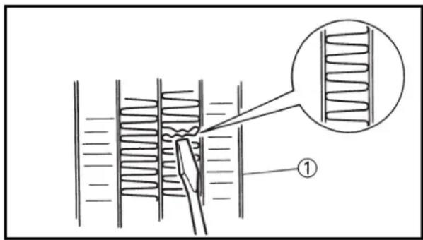
EC454000
INSPECTION
EC444100
Radiator
- Inspect:
- Radiator core ①
Obstruction → Blow out with compressed air through rear of the radiator.
Bent fin → Repair/replace.
REMARQUES CONCERNANT LA MANIPULATION
⚠ AVERTISSEMENT


EC455000
ASSEMBLY AND INSTALLATION
EC445343
Radiator
- Install:
•Radiator breather hose ①
•Radiator hose 3 ②
1 Nm (0.1 m•kg, 0.7 ft•lb)
•Radiator hose 1 ③
1 Nm (0.1 m•kg, 0.7 ft•lb)
To radiator (right) ④.
NOTE:
Clamp the radiator hose in the direction as shown.
CAUTION:
Push in the radiator hose 3 until it contacts the area ⓐ. Otherwise it may cause damage to the clutch cable.
- Install:
•Radiator (right) ①
•Bolt [radiator (right)] ②
10 Nm (1.0 m•kg, 7.2 ft•lb)
•Radiator hose 4 ③
1 Nm (0.1 m•kg, 0.7 ft•lb)
Refer to "CABLE ROUTING DIAGRAM" section in the CHAPTER 2.
- Install:
•Radiator (left) ①
•Bolt [radiator (left)] ②
10 Nm (1.0 m•kg, 7.2 ft•lb)
•Radiator hose 2 ③
1 Nm (0.1 m•kg, 0.7 ft•lb)
Refer to "CABLE ROUTING DIAGRAM" section in the CHAPTER 2.
- Tighten:
- Clamp (radiator hose 1, 3) ④
1 Nm (0.1 m•kg, 0.7 ft•lb)
- Install:
-Panel ①
- Bolt (panel) ②
10 Nm (1.0 m•kg, 7.2 ft•lb)
NOTE:
Fit the hook @on the inner side first into the radiator.
REMONTAGE ET MONTAGE
Radiateur
- Monter:
CARBURETOR AND REED VALVE


Extent of removal:
① Carburetor removal
② Reed valve removal
| Extent of removal Order Part name Q'ty Remarks | |||
| Preparation for Fuel tank Refer to “SEAT, FUEL TANK AND removal SIDE COVERS” section. | |||
| 12 | 1 Clamp (carburetor joint) 22 Carburetor 13 Carburetor joint 14 Reed valve assembly 15 Stopper (reed valve) 26 Reed valve 2 | Loosen the screws (carburetor joint). | |

CARBURATEUR ET SOUPAPE FLEXIBLE
Etendue de dépose:
Extent of removal:
① Carburetor disassembly
| Extent of removal Order Part name Q'ty Remarks | |||
| 1 | CARBURETOR DISASSEMBLY1Mixing chamber top 12Throttle valve 1 Refer to “REMOVAL POINTS”.3Needle holder 14Jet needle 15Float chamber 16Needle jet cover 17Float pin 18Float 19Valve seat10Main jet11Main jet holder12Pilot jet13Starter plunger14Throttle stop screw15Pilot air screw 1 | ||
DEMONTAGE DU CARBURATEUR

EC466030
HANDLING NOTE
CAUTION:
Do not disassemble the venturi block ①① and main nozzle ② because it will cause a drop in carburetor performance.
EC463000
REMOVAL POINTS
EC463110
Throttle valve
-
Remove:
-
Throttle valve ①
•Ring ② - Spring (throttle valve) ③
- Mixing chamber top ④
- Throttle cable ⑤
NOTE:
While compressing the spring (throttle valve), disconnect the throttle cable.

natural_image
Line drawing of a hand using a gun to adjust a device (no text or symbols present)
EC464000
INSPECTION
EC464140
Carburetor
- Inspect:
•Carburetor body
Contamination → Clean.
CAUTION:
When cleaning the main air passage a_2 do not blow air at the filter side because it will clog the passage with mud or sand.
NOTE:
- Use a petroleum based solvent for cleaning. Blow out all passages and jets with compressed air.
- Never use a wire.
- When cleaning the main air passage, blow air through it while covering the nozzle with a clean rag.
REMARQUES CONCERNANT LA MANIPULATION
ATTENTION:

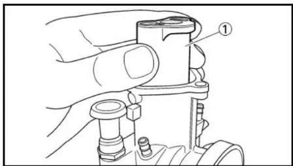

2. Inspect:
- Main jet ①
- Main jet holder ②
- Pilot jet ③
Contamination → Clean.
NOTE:
- Use a petroleum based solvent for cleaning. Blow out all passages and jets with compressed air.
- Never use a wire.
EC464200
Needle valve
-
Inspect:
-
Needle valve ①
- Valve seat ②
Grooved wear ⓐ →Replace.
Dust ⓑ→Clean.
NOTE:
Always replace the needle valve and valve seat as a set.
EC464301
Throttle valve
- Check:
- Free movement
Stick → Repair or replace.
NOTE:
Insert the throttle valve ① into the carburetor body, and check for free movement.
EC464401
Jet needle
-
Inspect:
-
Jet needle ①
Bends/Wear →Replace. - Clip groove
Free play exists/Wear →Replace. - Clip position

Standard clip position:
No.3 Groove
*No.4 Groove
*For EUROPE
CARBURATEUR ET SOUPAPE FLEXIBLE VERGASER UND ZUNGENVENTIL CARBURATORE E VALVOLA A LAMELLA
ENG

2. Examiner:
natural_image
Technical line drawing of a mechanical assembly with labeled component (1), no readable text or symbols present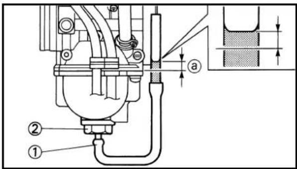
EC464A00
Filter
- Inspect:
•Filter ①
Damage → Replace.
NOTE:
Inspect the filter as it is assembled to the carburetor. Do not remove the filter except when replacing it.
EC464802
Fuel level
- Measure:
- Fuel level ⓐ
Out of specification → Adjust.

Fuel level:
9.5\~10.5 mm (0.37\~0.41 in)
Above the float chamber
mating surface
Measurement and adjustment steps:
- Remove the drain plug.
- Connect the fuel level gauge adapter ② and fuel level gauge ① to the float chamber.

Fuel level gauge adapter:
YM-01470/90890-01470
Fuel level gauge:
YM-1312-A/90890-01312
- Hold the fuel level gauge vertically next to the float chamber mating surface.
- Measure the fuel level with the fuel level gauge.
NOTE:
Keep the carburetor and fuel level gauge vertically when measuring the fuel level.

natural_image
Technical line drawing of a mechanical clamp or bracket assembly (no text or symbols)- If the fuel level is not within specification, inspect the valve seat and needle valve.
- If either is worn, replace them both.
- If both are fine, adjust the fuel level by bending the float tab ⑥ on the float.
- Recheck the fuel level.
CARBURATEUR ET SOUPAPE FLEXIBLE VERGASER UND ZUNGENVENTIL CARBURATORE E VALVOLA A LAMELLA
ENG

Filtre
- Examiner:
•Filtre ①
natural_image
Technical line drawing of a mechanical component with two views, one showing internal structure and the other a bracket (no text or symbols)
natural_image
Simple line drawing of a mechanical structure with a base and a circular component labeled 'a' (no text or symbols beyond the label)
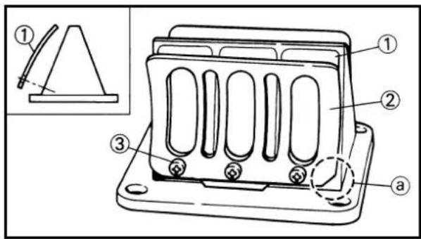
EC464600
Float
- Inspect:
-Float ①
Damage →Replace.
EC464701
Reed valve
- Measure:
- Reed valve bending ⓐ
Out of specification →Replace.

Reed valve bending limit: 0.2 mm (0.008 in)
- Valve stopper height ⑥
Out of specification →Adjust stopper/
Replace valve stopper.

Valve stopper height: 8.2 \~ 8.6 mm (0.323\~0.339 in)
EC465000
ASSEMBLY AND INSTALLATION
EC465190
Reed valve
-
Install:
-
Reed valve ①
-Stopper (reed valve) ② - Screw (reed valve) ③
1 Nm (0.1 m•kg, 0.7 ft•lb)
NOTE:
• Install the reed valve with the reed valve bending as shown.
- Note the cut @in the lower corner of the reed and stopper plate.
CAUTION:
Tighten each screw gradually to avoid warping.
CARBURATEUR ET SOUPAPE FLEXIBLE VERGASER UND ZUNGENVENTIL CARBURATORE E VALVOLA A LAMELLA
ENG

Flotteur
- Examiner:
- Flotteur ①


2. Install:
- Reed valve assembly ①
- Reed valve spacer ②
NOTE:
Install the reed valve spacer with its wider contact surface side @to the right.
3. Install:
- Carburetor joint ①
•Bolt (carburetor joint) ②
10 Nm (1.0 m•kg, 7.2 ft•lb)
EC4652C2
Carburetor
1. Install:
- Throttle stop screw ①
- Locknut ②
- Pilot air screw ③
Note the following installation points:
- Screw in the pilot air screw until it is lightly seated.
- Back out it by the specified number of turns.

Pilot air screw:
2 turns out
*1-1/2 turns out
*For EUROPE

natural_image
Technical line drawing of a mechanical assembly with labeled component (no text or symbols present)2. Install:
- Starter plunger ①
CARBURATEUR ET SOUPAPE FLEXIBLE VERGASER UND ZUNGENVENTIL CARBURATORE E VALVOLA A LAMELLA
ENG

2. Monter:
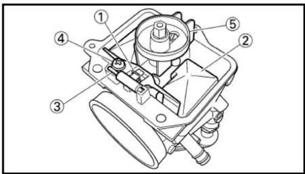
3. Install:
- Main jet holder ①
- Main jet ②
•Pilot jet ③ - Valve seat ④
- Screw (valve seat) ⑤
4. Install:
- Needle valve ①
-Float ②
-Float pin ③ - Screw (float pin) ④
- Needle jet cover ⑤
NOTE:
• After installing the needle valve to the float, install them to the carburetor.
- Check the float for smooth movement.

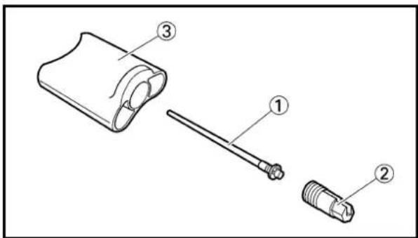
5. Install:
- Float chamber ①
- Plate ②
- Screw (float chamber) ③
6. Install:
- Jet needle ①
- Needle holder ②
To throttle valve ③.
3. Monter:


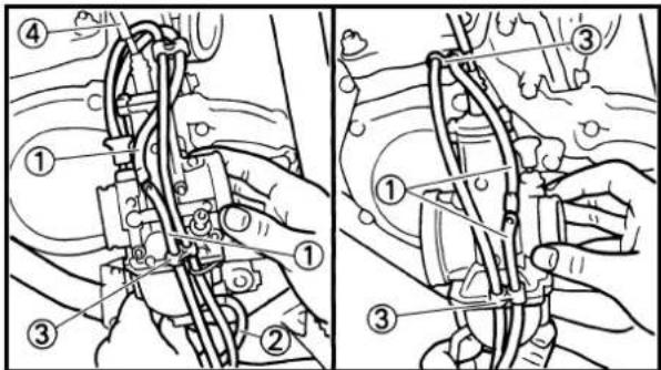

natural_image
Technical line drawing of a mechanical assembly with springs and gears (no text or symbols)7. Install:
- Throttle cable ①
•Mixing chamber top ② - Spring (throttle valve) ③
•Ring ④ - Throttle valve ⑤
NOTE:
- While compressing the spring, connect the throttle cable.
- Align the projection ①on the ring with the groove ⑥in the needle holder ⑥.
8. Install:
- Mixing chamber top ①
•Screw (mixing chamber top) ②
To carburetor ③.
NOTE:
After installing, check the throttle grip for smooth movement.
9. Install:
•Air vent hose ①
•Overflow hose ②
- Clamp ③
NOTE:
Pass the air vent hose at the rear (on the air cleaner side) of the throttle cable ④.
EC465352
Carburetor installation
1. Install:
•Carburetor ①
NOTE:
Install the projection between the carburetor joint slots.
CARBURATEUR ET SOUPAPE FLEXIBLE VERGASER UND ZUNGENVENTIL CARBURATORE E VALVOLA A LAMELLA
ENG

7. Monter:

2. Tighten:
- Screw (air filter joint) ①
•Screw (carburetor joint) ②
3. Clamp:
•Air vent hose ①
-Overflow hose ②
Refer to "CABLE ROUTING DIAGRAM" section in the CHAPTER 2.
4. Adjust:
- Idle speed Refer to "IDLE SPEED ADJUSTMENT" section in the CHAPTER 3.
CARBURATEUR ET SOUPAPE FLEXIBLE VERGASER UND ZUNGENVENTIL CARBURATORE E VALVOLA A LAMELLA
ENG

2. Serrer:
① Cylinder head removal
② Cylinder removal
| Extent of removal Order Part name Q'ty Remarks | ||||
| Preparation for Seat and fuel tank Refer to “SEAT, FUEL TANK AND removal SIDE COVERS” section.Exhaust pipe and silencer Refer to "EXHAUST PIPE AND SILENCER" section.Radiator hose 2 Disconnect at cylinder head side.Bolt (radiator) Refer to “RADIATOR” section.Radiator hose 3 Disconnect at right side radiator, then shift the radiators forward. | ||||
 | 1 Spark plug 12 Engine bracket 23 Nut (cylinder head) 54 Cylinder head 15 Power valve housing 16 Push rod7 Nut (cylinder)8 Cylinder | Refer to “REMOVAL POINTS”. | ||
PISTON AND POWER VALVE
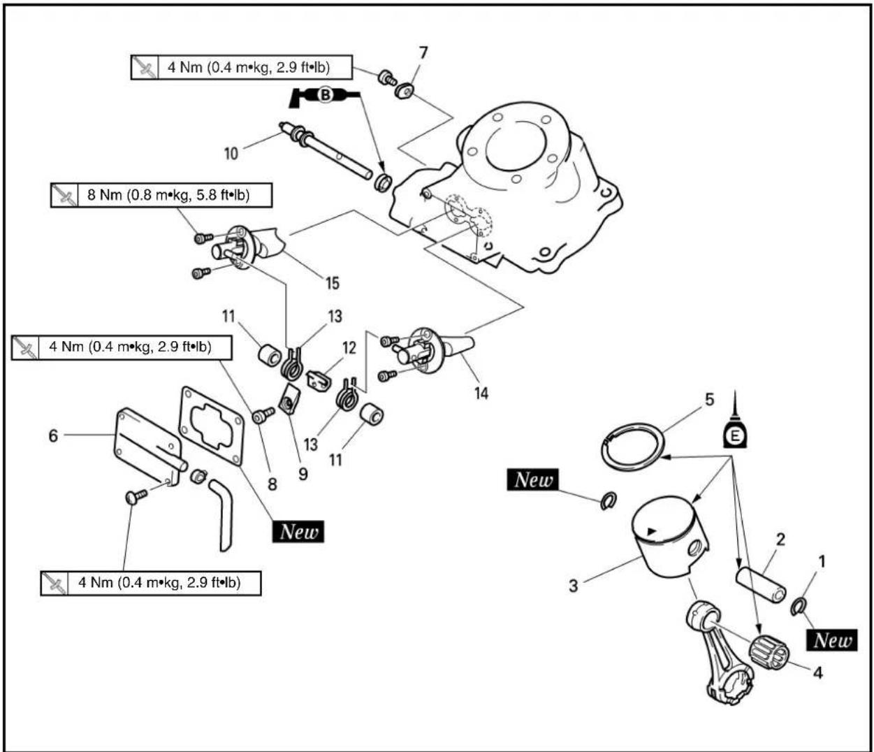
Extent of removal:
① Piston and piston ring removal
② Power valve removal
| Extent of removal Order Part name Q'ty Remarks | |||
 | PISTON AND POWER VALVE REMOVAL1 Piston pin clip 22 Piston pin 13 Piston 1 Refer to “REMOVAL POINTS”.4 Small end bearing 15 Piston ring 16 Power valve cover 17 Thrust plate 18 Bolt (link lever) 19 Valve holder 110 Valve shaft11 Collar12 Link lever13 Spring14 Power valve 115 Power valve 2 | 1 | 2 |
PISTON ET CLAPET DE PUISSANCE
Etendue de dépose:


EC473000
REMOVAL POINTS
EC473210
Push rod
Set the collar ③included in owner's tool kit to remove the bolt (push rod).
EC473402
Piston and piston ring
- Remove:
- Piston pin clip ①
NOTE:
Before removing the piston pin clip, cover the crankcase with a clean rag to prevent the piston pin clip from falling into the crankcase cavity.
- Remove:
•Piston pin ①
- Piston ②
- Small end bearing ③
NOTE:
Before removing the piston pin, deburr the clip groove and pin hole area. If the piston pin groove is deburred and piston pin is still difficult to remove, use the piston pin puller ④.

Piston pin puller: YU-1304/90890-01304
CAUTION:
Do not use a hammer to drive the piston pin out.
- Remove:
- Piston ring ①
NOTE:
Take care not to scratch the piston or damage the piston ring by expanding it more than necessary.
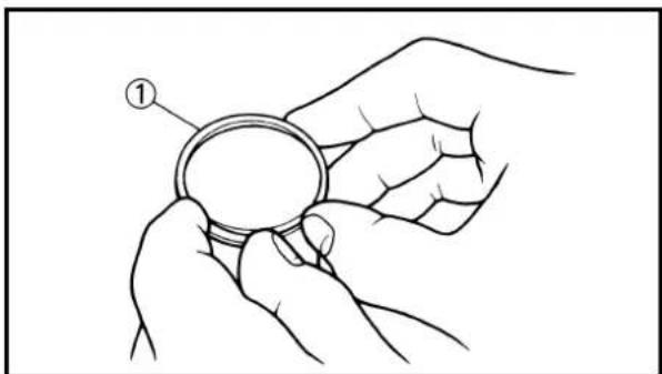
natural_image
Line drawing of a hand holding a circular ring, with no text or symbols presentPOINTS DE DEPOSE
natural_image
Technical diagram of a mechanical component with a tool inserted, showing internal structure and part number 1 (no text or symbols present)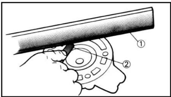

EC474000
INSPECTION
EC474102
Cylinder head
- Eliminate:
•Carbon deposits
Use a rounded scraper ①.
NOTE:
Take care to avoid damaging the spark plug threads. Do not use a sharp instrument. Avoid scratching the aluminum.
- Inspect:
•Cylinder head water jacket
Crust of minerals/Rust → Remove.
•Cylinder head warpage
Out of specification → Re-surface.
Warpage measurement and re-surface-ment steps:
- Attach a straightedge ①and a thickness gauge ②on the cylinder head.
- Measure the warpage.

Warpage limit: 0.03 mm(0.0012 in)
- If the warpage is out of specification, resurface the cylinder head.
- Place # 400\~600 grit wet sandpaper ③ on the surface plate, and re-surface the head ④ using a figure-eight sanding pattern.
NOTE:
Rotate the cylinder head several times to avoid removing too much material from one side.

EC474201
Cylinder
- Eliminate:
•Carbon deposits
Use a rounded scraper ①.
NOTE:
Do not use a sharp instrument. Avoid scratching the aluminum.
VERIFICATION
Culasse
- Éliminer:
natural_image
Line drawing of hands assembling a mechanical component (no text or symbols)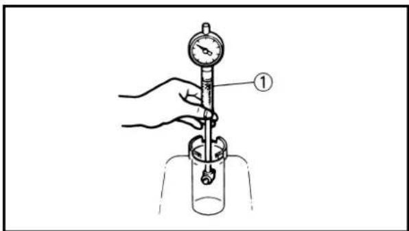


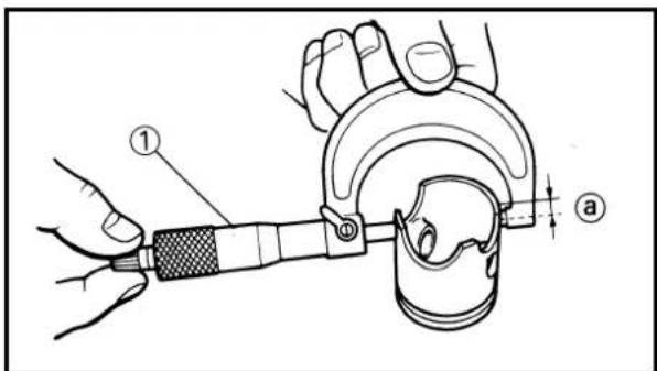
- Inspect:
- Cylinder inner surface Score marks → Repair or replace. Use #400\~600 grit wet sandpaper.
CAUTION:
Do not rebore the cylinder.
- Measure:
- Cylinder bore "C" Use cylinder gauge ①. Out of limit →Replace.
NOTE:
Measure the cylinder bore "C" in parallel (A, B, C) to and at right angles to the crankshaft (a, b). Then, find the average of the measurements.
| Standard Wear | limit | |
| Cylinder bore “C” | 54.000~54.014mm(2.1260~2.1265 in) (2.130 in) | 54.1 mm |
| Taper “T” | — | 0.05 mm(0.0020 in) |
| C=Maximum Aa~CbT=(Maximum Aa, or Ab) —(Maximum Ba, or Bb) | ||
EC474302
Piston
- Eliminate:
- Carbon deposits From the piston crown ⓐ and ring groove ⑥.
- Inspect:
- Piston wall Score marks → Repair or replace.
- Measure:
- Piston skirt diameter Use micrometer ①. Measure the specific distance @from the bottom edge. Out of specification →Replace.
| Distance a | Piston dia. | |
| 17.5 mm 53.957~53.972 mm(0.69 in) (2.1243~2.1249 in) | ||
CULASSE, CYLINDRE ET PISTON ZYLINDERKOPF, ZYLINDER UND KOLBEN TESTA CILINDRO, CILINDRO E PISTONE
ENG
2. Examiner:
natural_image
Technical line drawing of two mechanical components: a cylindrical roller and a flanged roller (no text or symbols)

EC474402
Piston pin and small end bearing
-
Inspect:
-
Piston pin
•Small end bearing
Signs of heat discoloration →Replace.
- Measure:
•Piston pin outside diameter
Use micrometer ①.
Out of limit →Replace.
| Piston pin outside diameter: | |
| Standard | |
| 14.995~15.000 mm 14.975 mm(0.5904~0.5906 in) (0.5896 in) |
- Check:
- Free play (when the piston pin ① is in place in the piston ②)
There should be no noticeable for the play.
Free play exists →Replace piston pin and/or piston.
-
Install:
-
Small end bearing
- Piston pin
Into the small end of connecting rod.

natural_image
Illustration of a hand turning a mechanical component with pins (no text or symbols)- Check:
- Free play
There should be no noticeable free play.
Free play exists →Inspect the connecting rod for wear/Replace the pin and/or connecting rod as required.
CULASSE, CYLINDRE ET PISTON ZYLINDERKOPF, ZYLINDER UND KOLBEN TESTA CILINDRO, CILINDRO E PISTONE
ENG

EC474502
Piston ring
- Install:
- Piston ring
Into the cylinder.
Push the ring with the piston crown.
- Measure:
•End gap
Use a thickness gauge ①.
Out of limit →Replace.
| Ring end gap (installed): | |
| Standard | |
| 0.5~0.7 mm 1.2mm(0.020~0.028 in) (0.047 in) |

natural_image
Illustration of hands holding a circular object with a tool, no text or symbols present- Measure:
- Side clearance
Use a thickness gauge ①.
Out of limit →Replace piston and/or ring.
| Side clearance: | ||
| Standard | ||
| 0.035~0.070 mm 0.1mm(0.0014~0.0028 in) (0.004 in) | ||
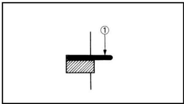
NOTE:
Check at several points.
EC474602
Piston clearance
- Calculate:
- Piston clearance
Out of limit →Replace piston, and piston ring and/or cylinder.
Refer to "Cylinder" and "Piston".
| PISTON CLEARANCE | CYLINDER BORE | PISTON DIAMETER |
Segment
1. Monter:
•Segment
Dans le cylindre.
| Piston clearance: | |
| Standard | |
| 0.040~0.045 mm 0.1 mm(0.0016~0.0018 in) (0.004 in) |

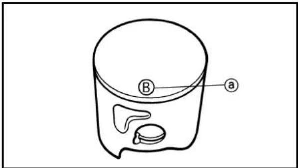
EC474700
Combination of piston and cylinder
1. Check:
•Cylinder mark ⓐ
| Cylinder mark a | Cylinder size |
| A | 54.000~54.002 mm(2.1260~2.1261 in) |
| B | 54.004~54.006 mm(2.1261~2.1262 in) |
| C | 54.008~54.010 mm(2.1263~2.1264 in) |
| D | 54.012~54.014 mm(2.1265~2.1265 in) |
2. Check:
- Piston mark ⓐ
| Piston mark ⓐ (color) | Piston size |
| A(red) | 53.957~53.960 mm(2.1243~2.1244 in) |
| B (orange) | 53.961~53.964 mm(2.1244~2.1246 in) |
| C (green) | 53.965~53.968 mm(2.1246~2.1247 in) |
| D (purple) | 53.969~53.972 mm(2.1248~2.1249 in) |
3. Combination:
Combine the piston and cylinder by the following chart.
| Cylinder mark Piston mark (color) | |
| A A (red) | |
| B B (orange) | |
| C C (green) | |
| D D (purple) | |
NOTE:
When you purchase a cylinder, you cannot designate its size. Choose the piston that matches the above chart.
CULASSE, CYLINDRE ET PISTON ZYLINDERKOPF, ZYLINDER UND KOLBEN TESTA CILINDRO, CILINDRO E PISTONE
ENG

| Jeu de piston: | ||
| Standard | ||
| 0,040~0,045 mm(0,0016~0,0018 in) | 0,1 mm(0,004 in) | |
| Kolbenspiel: | |
| Standard | |
| 0,040~0,045 mm(0,0016~0,0018 in) | 0,1 mm(0,004 in) |

EC474831
Power valve
- Inspect:
•Power valve 1,2①
Wear/Damage →Replace.
Carbon deposits → Remove.
- Valve holder ②
- Link lever ③
- Valve shaft ④
•Collar ⑤
Wear/Damage →Replace.
•Spring ⑥
Broken →Replace.
EC474901
Power valve hole on cylinder
- Remove:
•Carbon deposits
From power valve hole surface ⓐ.
NOTE:
Do not use a sharp instrument. Avoid scratching the aluminum.

EC475000
ASSEMBLY AND INSTALLATION
EC4751A1
Power valve
- Install:
•Power valve 1 ①
•Power valve 2 ②
•Bolt (power valve) ③
8 Nm (0.8 m•kg, 5.8 ft•lb)
NOTE:
Install the power valve at cut-away faced @for down side.
Clapet de puissance
1. Examiner:
2. Install:
•Spring ①
- Link lever ②
•Collar ③
- Valve shaft ④
-Valve holder ⑤
- Bolt (link lever) ⑥
4 Nm (0.4 m•kg, 2.9 ft•lb)
NOTE:
• Install the spring to the link lever, and then to the cylinder.
- Install the spring with its stopper portion @facing inward.
- Apply the lithium soap base grease on the oil seal lip.

3. Install:
- Thrust plate ①
- Screw (thrust plate) ②
4 Nm (0.4 m•kg, 2.9 ft•lb)

natural_image
Line drawing of a hand turning a valve into a mechanical component (no text or symbols)4. Check:
- Power valve smooth movement Unsmooth movement → Repair or replace.

5. Install:
New
•Gasket (power valve cover) ①
•Power valve cover ②
•Screw (power valve cover) ③
4 Nm (0.4 m•kg, 2.9 ft•lb)
-YPVS breather hose ④
NOTE:
• Install the power valve cover so that the arrow mark @faces upward.
• Install the clamp of the YPVS breather hose with its opening portion ⑥ facing backward.
CULASSE, CYLINDER ET PISTON ZYLINDERKOPF, ZYLINDER UND KOLBEN TESTA CILINDRO, CILINDRO E PISTONE
ENG
2. Monter:


EC475280
Piston ring and piston
- Install:
- Piston ring ①
NOTE:
•Take care not to scratch the piston or damage the piston ring.
- Align the piston ring gap with the pin ②.
•After installing the piston ring, check the smooth movement of it.
- Install:
•Gasket (cylinder) ①
New
- Small end bearing ②
•Dowel pin ③
NOTE:
-
Apply the engine oil onto the bearing (crankshaft and connecting rod) and connecting rod big end washers.
• Install the gasket with the seal print side toward the crankcase. -
Install:
•Piston ①
•Piston pin ② New
•Piston pin clip ③
NOTE:
- The arrow @on the piston dome must point to exhaust side.
- Before installing the piston pin clip, cover the crankcase with a clean rag to prevent the piston pin clip from falling into the crankcase cavity.
CAUTION:
- When installing the piston pin clip, use the hand so that it may not be distorted.
- Do not allow the clip open ends to meet the piston pin slot ⑥.
Segment et piston
- Monter:
- Segment ①
N.B.:

natural_image
Line drawing of a hand holding a tool with a labeled component (no text or symbols present)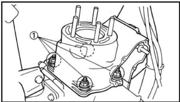
natural_image
Technical line drawing of a mechanical assembly with no visible text or symbols

EC4753A2
Cylinder head and cylinder
- Apply:
- Engine oil To piston ①, piston ring ② and cylinder surface.
- Install:
•Cylinder ①
CAUTION:
Make sure the piston ring is properly positioned. Install the cylinder with one hand while compressing the piston ring with the other hand.
NOTE:
After installing, check the smooth movement of the piston.
- Install:
- Nut (cylinder) ①
30 Nm (3.0 m•kg, 22 ft•lb)
NOTE:
Tighten the nuts in stage, using a crisscross pattern.
- Install:
•Collar ①
- Push rod ②
- Plain washer ③
- Bolt (push rod) ④
5 Nm (0.5 m•kg, 3.6 ft•lb)
NOTE:
- Set the collar ⑤included in owner's tool kit to install the bolt (push rod).
- Do not forget to remove the collar.
Culasse et cylindre
1. Appliquer:
•Huile du moteur


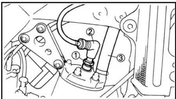
5. Install:
•Gasket (power valve housing)
New
•Power valve housing ①
•Bolt (power valve housing) ②
5 Nm (0.5 m•kg, 3.6 ft•lb)
6. Install:
•O-ring ①
New
NOTE:
Apply the lithium soap base grease on the O-rings.
7. Install:
•Cylinder head ①
•Copper washer ②
New
- Nut (cylinder head) ③
28 Nm (2.8 m•kg, 20 ft•lb)
NOTE:
Tighten the nuts (cylinder head) in stage, using a crisscross pattern.
8. Install:
-Engine bracket ①
•Bolt (engine bracket) ②
34 Nm (3.4 m•kg, 24 ft•lb)
•CDI unit bracket ③
•Engine mounting bolt (upper) ④
34 Nm (3.4 m•kg, 24 ft•lb)
9. Install:
•Spark plug ①
20 Nm (2.0 m•kg, 14 ft•lb)
- Spark plug cap ②
•Radiator hose 2 ③
1 Nm (0.1 m•kg, 0.7 ft•lb)
CULASSE, CYLINDER ET PISTON ZYLINDERKOPF, ZYLINDER UND KOLBEN TESTA CILINDRO, CILINDRO E PISTONE
ENG

5. Monter:
The Ground Truth image displays a single, solid horizontal line. According to Rule 2 (UNDERSCORE & LINE RULES), if the GT contains lines used for stylistic emphasis or as background elements (like ruled paper), the OCR result must ignore them. The line in the GT is clearly a stylistic or background line, not a placeholder for text. Therefore, the OCR should not have output any underscores. Outputting `____` constitutes an error under Rule 2, as it hallucinates placeholder symbols where none are semantically intended. No punctuation mismatch or formatting transformation applies here because the content is purely symbolic and not textual.
9. Installare:
•Candela ①
20 Nm (2,0 m•kg, 14 ft•lb)
CLUTCH AND PRIMARY DRIVEN GEAR EC498000
CLUTCH PLATE AND FRICTION PLATE


Extent of removal:
① Clutch plate and friction plate removal
| Extent of removal Order Part name Q'ty Remarks | |||
| Preparation for Drain removal | the transmission oil.Bolt (brake pedal) Shift the brake pedal downward.Clutch cable Disconnect at engine side. | Refer to “TRANSMISSION OIL REPLACE-MENT” section in the CHAPTER 3. | |
| 1 Clutch cover 12 Screw (clutch spring) 53 Clutch spring 54 Pressure plate 15 Push rod 16 Plain washer 27 Bearing 18 Friction plate 89 Clutch plate | 7 | ||
EMBRAYAGE ET PIGNON MENE PRIMAIRE DISQUE D'EMBRAYAGE ET DISQUE DE FRICTION

Extent of removal: ①
Primary driven gear removal
② Push lever removal
| Extent of removal Order Part name Q'ty Remarks | ||||
| [6754]2 | 1 Nut (clutch boss) 12 Lock washer 13 Clutch boss 14 Plain washer [ 34 mm (1.34 in)] 15 Primary driven gear 16 Bearing 17 Plain washer [ 34 mm (1.34 in)]8 Push lever 1 | PRIMARY DRIVEN GEAR REMOVALPlain washer [ 34 mm (1.34 in)] 1Plain washer [ 34 mm (1.34 in)]8 Push lever 1 | 1 | Use special tool.Refer to “REMOVAL POINTS”. |
PIGNON MENE PRIMAIRE
Etendue de dépose:
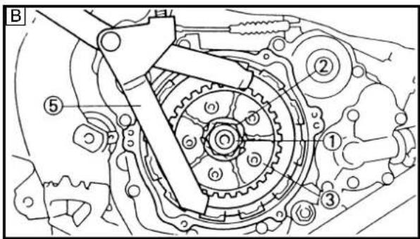

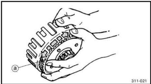
natural_image
Line drawing of hands assembling a mechanical component (no text or symbols)
natural_image
Line drawing of a hand adjusting a spring component with a coiled spring (no text or symbols)EC493000
REMOVAL POINTS
EC483211
Clutch boss
- Remove:
•Nut ①
- Lock washer ②
- Clutch boss ③
NOTE:
Straighten the lock washer tab and use the clutch holding tool ④, ⑤ to hold the clutch boss.

Clutch holding tool:
YM-91042....④④
90890-04086....⑤
A For USA and CDN
B Except for USA and CDN
EC494000
INSPECTION
EC484100
Clutch housing and boss
-
Inspect:
-
Clutch housing ①
Cracks/Wear/Damage → Replace. - Clutch boss ②
Scoring/Wear/Damage > Replace.
EC484201
Primary driven gear
- Check:
•Circumferential play
Free play exists → Replace.
•Gear teeth a
Wear/ Damage → Replace.
EC484400
Clutch spring
- Measure:
- Clutch spring free length ⓐ
Out of specification → Replace springs as a set.

Clutch spring free length:
Standard
41.2 mm 39.2 mm
(1.622 in) (1.543 in)
EMBRAYAGE ET PIGNON MENE PRIMAIRE KUPPLUNG UND PRIMÄRABTRIEBSZAHNRAD FRIZIONE E INGRANAGGIO CONDOTTO PRIMARIO
ENG

POINTS DE DEPOSE
Noix d'embrayage
- Déposer:
(1,622 in) (1,543 in)
| Valore normale | |
| 41,2 mm(1,622 in) | 39,2 mm(1,543 in) |

natural_image
Line drawing of a hand using a tool to measure a circular mechanical component (no text or symbols)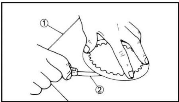

natural_image
Technical line drawing of two mechanical components: a handle and a flanged part (no text or symbols)
natural_image
Technical line drawing of a mechanical fan or impeller component with labeled part 'a' (no text or symbols beyond label)EC484500
Friction plate
1. Measure:
- Friction plate thickness Out of specification →Replace friction plate as a set. Measure at all four points.
| Friction plate thickness: | ||
| Standard | ||
| 2.9~3.1 mm 2.8 mm(0.114~0.122 in) (0.110 in) | ||
EC484600
Clutch plate
1. Measure:
- Clutch plate warpage Out of specification →Replace clutch plate as a set. Use a surface plate ①and thickness gauge ②.
| Warp limit:0.2 mm (0.008 in) |
EC494100
Push lever and push rod
1. Inspect:
- Push lever ① - Push rod ② Wear/Damage →Replace.
EC494200
Clutch cover
1. Inspect:
- Push rod bearing portion (a) Wear/Damage →Replace.
EMBRAYAGE ET PIGNON MENE PRIMAIRE KUPPLUNG UND PRIMÄRABTRIEBSZAHNRAD FRIZIONE E INGRANAGGIO CONDOTTO PRIMARIO
ENG
Disque de friction
1. Mesurer:


natural_image
Technical line drawing of a mechanical gear assembly (no text or symbols)EC495000
ASSEMBLY AND INSTALLATION
EC495240
Clutch
-
Install:
-
Plain washer [φ34 mm (1.34 in)] ①
- Spacer ②
- Bearing ③
• Primary driven gear ④
NOTE:
Apply the transmission oil on the spacer, bearing and primary driven gear inner circumference.
-
Install:
-
Plain washer [φ34 mm (1.34 in)] ①
-
Clutch boss ②
-
Install:
-
Lock washer ① New
- Nut (clutch boss) ②
80 Nm (8.0 m•kg, 58 ft•lb)
NOTE:
Use the clutch holding tool ③, ④ to hold the clutch boss.

Clutch holding tool: YM-91042....③③ 90890-04086....④④
A For USA and CDN
B Except for USA and CDN
- Bend the lock washer ①tab.
REMONTAGE ET MONTAGE
Embrayage
- Monter:
•Rondelle ordinaire [ 34 mm (1,34 in)] ①
- Entretoise ②
•Roulement ③
•Pignon mené primaire ④
N.B.:
80 Nm (8,0 m•kg, 58 ft•lb)
N.B:
80 Nm (8,0 m•kg, 58 ft•lb)
HINWEIS:
80 Nm (8,0 m•kg, 58 ft•lb)
NOTA:

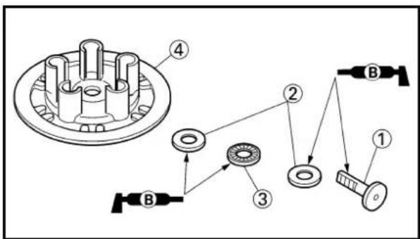
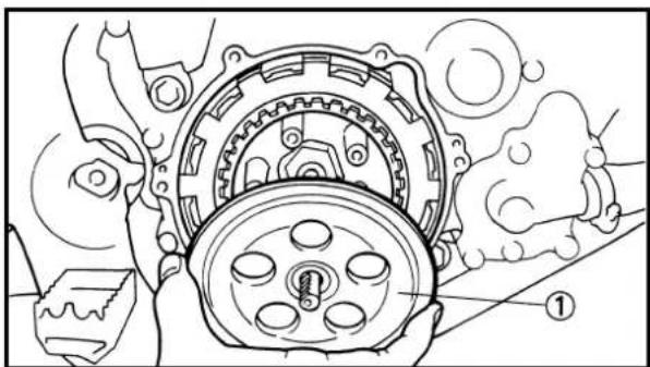
natural_image
Mechanical assembly diagram showing gears and a central rotating component (no text or symbols)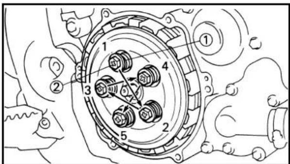
5. Install:
- Friction plate 1 ①
- Clutch plate ②
- Friction plate 2 ③
NOTE:
• Install the clutch plates and friction plates alternately on the clutch boss, starting with a friction plate and ending with a friction plate.
- Use the friction plates 1 for the first and final while paying attention to the difference in surface pattern.
- Apply the transmission oil on the friction plates and clutch plates.
6. Install:
- Push rod ①
- Plain washer ②
•Bearing ③
To pressure plate ④.
NOTE:
Apply the lithium soap base grease on the bearing, plain washer and push rod.
7. Install:
-Pressure plate ①
8. Install:
- Clutch spring ①
- Screw (clutch spring) ②
10 Nm (1.0 m•kg, 7.2 ft•lb)
NOTE:
Tighten the screws in stage, using a crisscross pattern.
EMBRAYAGE ET PIGNON MENE PRIMAIRE KUPPLUNG UND PRIMÄRABTRIEBSZAHNRAD FRIZIONE E INGRANAGGIO CONDOTTO PRIMARIO
ENG

5. Monter:


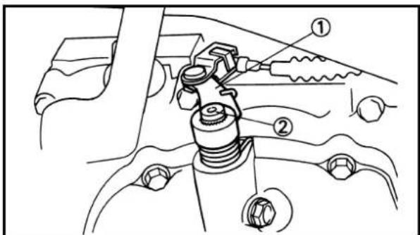
- Install:
•Gasket (clutch cover) ① New
NOTE:
Position the rack ⓐon the push rod backward.
- Install:
- Clutch cover ①
- Bolt (clutch cover) ②
10 Nm (1.0 m•kg, 7.2 ft•lb)
NOTE:
Tighten the bolts in stage, using a crisscross pattern.
EC495122
Push lever
- Install:
•Torsion spring ①
- Push lever ②
To push lever axle ③.
NOTE:
Temporarily install the torsion spring and push lever at this point.
- Check:
- Push lever position
NOTE:
When pushing the push lever forward, alignment mark ⓑ should be positioned between area Ⓐ. If not, reinstall the push lever.
- Adjust:
- Push lever position
Adjustment steps:
- Remove the push lever ① from the push lever axle ②.
- Re-install the push lever so that the projection is positioned between alignment marks when pushing the push lever forward.
EMBRAYAGE ET PIGNON MENE PRIMAIRE KUPPLUNG UND PRIMÄRABTRIEBSZAHNRAD FRIZIONE E INGRANAGGIO CONDOTTO PRIMARIO
ENG

- Monter:
-
Install:
-
Plain washer ①
•Circlip ② New
EMBRAYAGE ET PIGNON MENE PRIMAIRE KUPPLUNG UND PRIMÄRABTRIEBSZAHNRAD FRIZIONE E INGRANAGGIO CONDOTTO PRIMARIO
ENG
- Monter:
•Rondelle ordinaire ①
•Circlip ② New
- Einbauen:
- Beilegescheibe ①
•Sprengring ② New
- Installare:
- Rossetta ①
KICK AXLE, SHIFT SHAFT AND PRIMARY DRIVE GEAR
EC4C8000 PRIMARY DRIVE GEAR

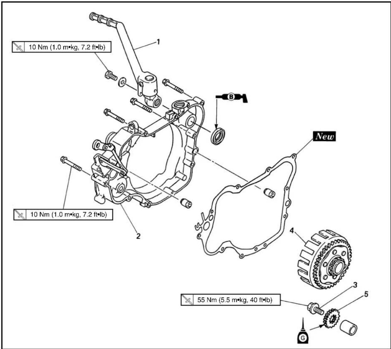
Extent of removal:
① Primary drive gear removal
| Extent of removal Order Part name Q'ty Remarks | ||||
| Preparation for Drain removal | the tran | RPIMARY DRIVE GEAR REMOVAL transmission oil. Clutch cable Disconnect at engine side. Bolt (brake pedal) Shift the brake pedal downward. Radiator hose 4 Disconnect at water pump side. Bolt (push rod) | Refer to “TRANSMISSION OIL REPLACE-MENT” section in the CHAPTER 3. | |
| downward. Refer to “CYLINDER HEAD, CYLINDER AND PISTON” section. | ||||
| 1 Kick starter 12 Crankcase cover (right) 13 Bolt (Primary drive gear) 1 Only loosening4 Primary driven gear 1 Refer to “CLUTCH AND PRIMARYDRIVEN GEAR”section. | Refer to “REMOVAL POINTS”. | |||
| PRIMARYDRIVEN GEAR”section. | ||||
AXE DE DEMARREUR AU PIED, ARBRE DE SELECTEUR ET PIGNON DE TRANSMISSION PRIMAIRE PIGNON DE TRANSMISSION PRIMAIRE

KICK AXLE AND SHIFT SHAFT

Extent of removal: ①Kick axle and kick idle gear removal
②Shift shaft and stopper lever removal
| Extent of removal Order Part name Q'ty Remarks | ||||
| (ZZDC) | (Cowest) | KICK AXLE AND SHIFT SHAFT REMOVAL1 Kick idle gear 12 kick axle assembly 1 Refer to “REMOVAL POINTS”.3 Shift pedal 14 Shift shaft 15 Roller 16 Shift guide 17 Shift lever assembly 18 Stopper lever 1 | Refer to “REMOVAL POINTS”. | |
AXE DE DEMARREUR AU PIED ET ARBRE DE SELECTEUR
Etendue de dépose:
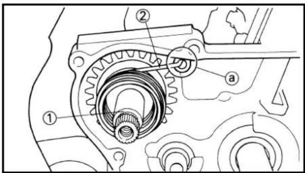


EC4C3000
REMOVAL POINTS
EC483111
Primary drive gear
- Loosen:
•Bolt (primary drive gear) ①
NOTE:
Place an aluminum plate ①between the teeth of the primary drive gear ② and driven gear ③.
EC4B3101
Kick axle assembly
- Remove:
- Kick axle assembly ①
NOTE:
Unhook the torsion spring ② from the hole ⓐ in the crankcase.
EC4C3101
Shift guide and shift lever assembly
-
Remove:
-
Bolt (shift guide)
- Shift guide ①
- Shift lever assembly ②
NOTE:
The shift lever assembly is disassembled at the same time as the shift guide.
EC4C4000
INSPECTION
EC4B4100
Kick axle and kick gear
- Check:
- Kick gear smooth movement
Unsmooth movement →Replace.
- Inspect:
- Kick axle ①
Wear/Damage →Replace.
EC4B4200
Kick gear and kick idle gear
-
Inspect:
-
Kick gear ①
- Kick idle gear ②
•Gear teeth ⓐ
Wear/Damage →Replace.
POINTS DE DEPOSE
Pignon de transmission primaire
- Desserrer:
natural_image
Illustration of a hand using a spring scale to measure a mechanical component (no text or symbols present)
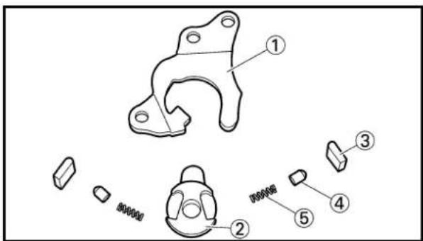

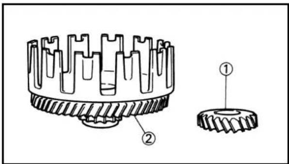
EC4B4300
Kick gear clip
- Measure:
- Kick clip friction force Out of specification →Replace. Use a spring gauge ①.

Kick clip friction force: 0.8\~1.2 kg (1.8\~2.6 lb)
EC4B4400
Shift shaft
- Inspect:
- Shift shaft ① Bend/Damage →Replace. - Spring ② Broken →Replace.
EC4C4100
Shift guide and shift lever assembly
- Inspect:
- Shift guide ① - Shift lever ② - Pawl ③ - Pawl pin ④ - Spring ⑤ Wear/Damage →Replace.
EC4E4100
Stopper lever
- Inspect:
- Stopper lever ① Wear/Damage →Replace. - Bearing ② Rotate outer race with a fin Rough spot/Seizure →Repl lever. - Torsion spring ③ Broken →Replace.
EC484300
Primary drive gear and primary driven gear
- Inspect:
- Primary drive gear ① - Primary driven gear ② Wear/Damage →Replace.
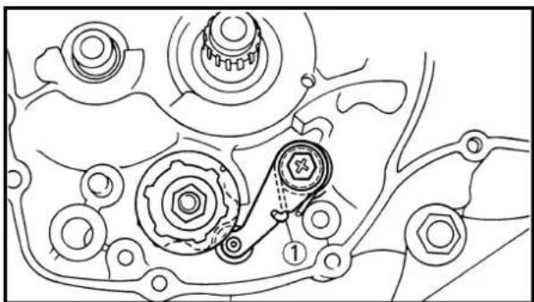
natural_image
Technical line drawing of a mechanical assembly with gears and shafts (no text or symbols)

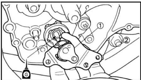
EC4C5000
ASSEMBLY AND INSTALLATION
EC4C5120
Stopper lever
- Install:
•Torsion spring ①
- Stopper lever ②
- Spacer ③
- Bolt (stopper lever) ④
10 Nm (1.0 m•kg, 7.2 ft•lb)
NOTE:
- Align the stopper lever roller with the slot on segment.
- When installing the stopper lever, make sure that the torsion spring is in the position as shown.
EC4C5202
Shift guide and shift lever assembly
-
Install:
-
Spring ①
•Pawl pin ②
•Pawl ③
To shift lever ④.
- Install:
- Shift lever assembly ①
To shift guide ②.
-
Install:
-
Shift lever assembly ①
- Shift guide ②
NOTE:
- The shift lever assembly is installed at the same time as the shift guide.
- Apply the transmission oil on the bolt (segment) shaft.
REMONTAGE ET MONTAGE
Levier de butée
- Monter:
KICK AXLE, SHIFT SHAFT AND PRIMARY DRIVE GEAR
ENG


natural_image
Mechanical assembly diagram showing gear and shaft components (no text or labels)


4. Install:
- Bolt (shift guide) ①

EC4C5301
Shift shaft
1. Install:
- Roller ①
- Shift shaft ②
NOTE:
Apply the transmission oil on the roller and shift shaft.
EC4B5302
Kick axle assembly
1. Install:
- Kick gear ①
- Plain washer ②
•Torsion spring ③
To kick axle ④.
NOTE:
Make sure the stopper ⓐ of the torsion spring fits into the hole ⓑ on the kick axle.
2. Install:
- Spring guide ①
NOTE:
Slide the spring guide into the kick axle, make sure the groove @in the spring guide fits on the stopper of the torsion spring.
3. Install:
- Kick axle assembly ①
NOTE:
- Apply the transmission oil on the kick axle.
- Slide the kick axle assembly into the crankcase, make sure the clip ② and kick axle stopper a fit into their home positions b, c.
AXE DE DEMARREUR AU PIED, ARBRE DE SELECTEUR ET PIGNON DE TRANSMISSION PRIMAIRE KICKSTARTERWELLE, SCHALTWELLE UND PRIMÄRANTRIEBSZAHNRAD PEDIVELLA, ALBERO DEL CAMBIO E INGRANAGGIO CONDUTTORE PRIMARIO
ENG

- Monter:
KICK AXLE, SHIFT SHAFT AND PRIMARY DRIVE GEAR
ENG

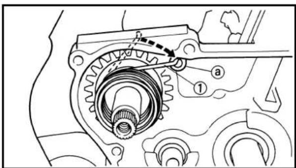
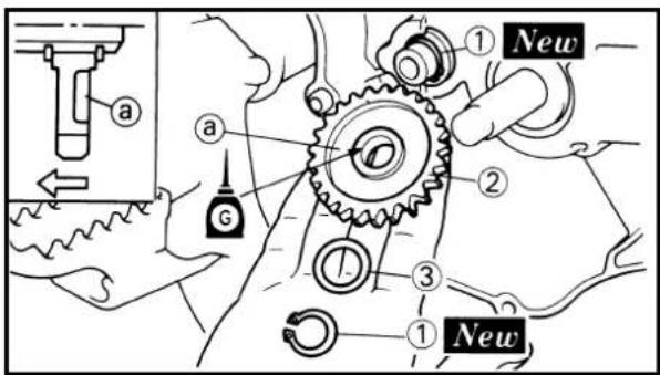


- Hook:
•Torsion spring ①
NOTE:
Turn the torsion spring clockwise and hook into the proper hole @in the crankcase.
EC4C5402
Kick idle gear
-
Install:
-
Circlip ① New
- Kick idle gear ②
- Plain washer ③
NOTE:
- Apply the transmission oil on the kick idle gear inner circumference.
• Install the kick idle gear with its depressed side @toward you.
EC4C5503
Primary drive gear
-
Install:
-
Spacer ①
•Primary drive gear ②
•Bolt ③
NOTE:
Temporarily tighten the bolt at this point.
- Install:
•Primary driven gear
Refer to "CLUTCH AND PRIMARY DRI-VEN GEAR" section.
- Tighten:
•Bolt (primary drive gear) ①
55 Nm (5.5 m•kg, 40 ft•lb)
NOTE:
Place an aluminum plate ① between the teeth of the primary drive gear ② and driven gear ③.
-
Install:
-
Dowel pin ①
•Gasket [crankcase cover (right)] ②
New
- Crocher:
KICK AXLE, SHIFT SHAFT AND PRIMARY DRIVE GEAR
ENG


natural_image
Technical line drawing of a mechanical assembly with gears and springs (no text or symbols)
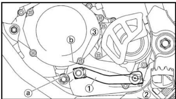
5. Install:
•Crankcase cover (right) ①
NOTE:
- Position the rack @on the push rod backward.
- Mesh the governor gear ②, and impeller shaft gear ③ with primary drive gear ④.
6. Install:
•Bolt [crankcase cover (right)] ①
10 Nm (1.0 m•kg, 7.2 ft•lb)
NOTE:
Tighten the bolts in stage, using a crisscross pattern.
7. Install:
- Kick starter ①
- Plain washer ②
- Bolt (kick starter) ③
10 Nm (1.0 m•kg, 7.2 ft•lb)
NOTE:
Install the kick starter closest to but not contacting the pillar tube ④.
8. Install:
- Shift pedal ①
- Bolt (shift pedal) ②
12 Nm (1.2 m•kg, 8.7 ft•lb)
NOTE:
Install the shift pedal so that the top of the shift pedal outer diameter ⓐis highest without exceeding the line ⓑconnecting the center of the shift shaft and the bottom of the screw [crankcase cover (left)] ③.
9. Check:
- Push lever position Refer to "CLUTCH AND PRIMARY DRI- VEN GEAR" section.
AXE DE DEMARREUR AU PIED, ARBRE DE SELECTEUR ET PIGNON DE TRANSMISSION PRIMAIRE KICKSTARTERWELLE, SCHALTWELLE UND PRIMÄRANTRIEBSZAHNRAD PEDIVELLA, ALBERO DEL CAMBIO E INGRANAGGIO CONDUTTORE PRIMARIO
ENG

5. Monter:
Extent of removal:
① YPVS governor removal and disassembly
| Extent of removal Order Part name Q'ty Remarks | |||
| Preparation for Crank case cover (right) | Refer to “KICK AXLE, SHIFT SHAFT AND PRIMARY DRIVE GEAR” section. | ||
| 1 | 1 Governor assembly 12 Dowel pin 1 Refer to “REMOVAL POINTS”.3 Retainer 14 Ball 45 Retainer weight 16 Plain washer 47 Thrust bearing 28 Collar 19 Plate 110 Compression spring11 Governor gear 112 Governor shaft | 1 | |
REGULATEUR YPVS

Etendue de dépose:
natural_image
Line drawing of a hand using a tool to adjust a mechanical component (no text or symbols present)


EC4K3000
REMOVAL POINTS
EC4K3100
Governor
- Remove:
- Dowel pin ①
NOTE:
While compressing the spring, remove the dowel pin.
EC4K4000
INSPECTION
EC4K4100
Governor groove
-
Inspect:
-
Plain washer ①
•Collar ②
Wear/Damage →Replace.
EC4K4200
Bearing
-
Inspect:
-
Thrust bearing ①
- Plain washer ②
Wear/Damage →Replace.
EC4K5000
ASSEMBLY AND INSTALLATION
EC4K5120
Governor
- Install:
•Governor gear ①
•Compression spring ②
- Plate ③
- Plain washer ④
- Thrust bearing ⑤
•Collar ⑥
- Retainer weight ⑦
To governor shaft ⑧.
NOTE:
Apply the lithium soap base grease on the thrust bearing.
POINTS DE DEPOSE
Régulateur
- Déposer:
•Goujon ①
N.B.:


-
Install:
-
Ball ①
- Retainer ②
To governor shaft ③.
NOTE:
Apply the transmission oil on the retainer and ball.
- Install:
- Dowel pin ①
NOTE:
- While compressing the spring, install the dowel pin.
-
Make sure the dowel pin fits into the groove @ in the retainer.
-
Install:
•Governor assembly ①
NOTE:
Align the groove ①in the governor with the fork ②and set the governor in the crankcase cover.
2. Monter:
•Bille ①
- Retenue ②
① Impeller shaft removal
② Oil seal removal
| Extent of removal Order Part name Q'ty Remarks | ||||
| Preparation for Cran kcase cover (right) | Refer to “KICK AXLE, SHIFT SHAFT AND PRIMARY DRIVE GEAR” section. | |||
 | 1 Water pump housing cover 12 Impeller 13 Plain washer 1 Refer to “REMOVAL POINTS”4 Impeller shaft 15 Bearing 16 Oil seal 2 | Refer to “REMOVAL POINTS”. | ||
POMPE A EAU

Etendue de dépose:
EC4G3000
REMOVAL POINTS
EC4G3110
Impeller shaft
-
Remove:
-
Impeller ①
- Plain washer ②
- Impeller shaft ③
NOTE:
Hold the impeller shaft on its width across the flats @with spanners, etc. and remove the impeller.

natural_image
Technical line drawing of an engine gear assembly (no text or symbols)EC4G3210
Oil seal
NOTE:
It is not necessary to disassemble the water pump, unless there is an abnormality such as excessive change in coolant level, discoloration of coolant, or milky transmission oil.

- Remove:
•Bearing ① - Remove:
- Oil seal ①

natural_image
Technical line drawing of a mechanical gear assembly with threaded shaft and central hub (no text or symbols)EC4G4000
INSPECTION
EC444200
Impeller shaft
-
Inspect:
-
Impeller shaft ①
Bend/Wear/Damage →Replace.
Fur deposits → Clean.
POINTS DE DEPOSE
Axe de turbine
- Déposer:
natural_image
Technical line drawing of a mechanical gear assembly with threaded shaft and central shaft (no text or symbols)


EC444300
Impeller shaft gear
- Inspect:
•Gear teeth a
Wear/Damage →Replace.
EC4H4600
Bearing
- Inspect:
•Bearing ①
Rotate inner race with a finger.
Rough spot/Seizure →Replace.
EC444400
Oil seal
- Inspect:
- Oil seal ①
Wear/Damage →Replace.
EC4G5000
ASSEMBLY AND INSTALLATION
EC4G5111
Oil seal
- Install:
- Oil seal ①
New
NOTE:
-
Apply the lithium soap base grease on the oil seal lip.
• Install the oil seal with its manufacture's marks or numbers facing the crankcase cover (right) ②. -
Install:
•Bearing ①
NOTE:
Install the bearing by pressing its outer race parallel.
IC444300


EC4G5220
Impeller shaft
- Install:
- Impeller shaft ①
NOTE:
•Take care so that the oil seal lip is not damaged or the spring does not slip off its position.
- When installing the impeller shaft, apply the lithium soap base grease on the oil seal lip and impeller shaft. And install the shaft while turning it.
-
Install:
-
Plain washer ①
- Impeller ②
14 Nm (1.4 m•kg, 10 ft•lb)
NOTE:
Hold the impeller shaft on its width across the flats @with spanners, etc. and install the im-peller.
-
Install:
-
Dowel pin ①
•Gasket (water pump housing cover) ②
New
- Install:
•Water pump housing cover ①
•Bolt (water pump housing cover) ②
10 Nm (1.0 m•kg, 7.2 ft•lb)
•Copper washer (coolant drain bolt) ③
- Coolant drain bolt ④
10 Nm (1.0 m•kg, 7.2 ft•lb)
Axe de turbine
- Monter:
- Axe de turbine ①
N.B.:
Extent of removal: ①CDI magneto removal
| Extent of removal Order Part name Q'ty Remarks | ||||
| Preparation for Seat removal SIDE COVERS | and fuel tank Refer to “SEAT, FUEL TANK AND BOLT [Radiator (left)] Refer to “RADIATOR” section.Disconnect the CDI magneto lead. | |||
| 1 | 1 Crankcase cover (left) 12 Nut (rotor) 1 Use special tool.3 Rotor 1 Refer to “REMOVAL POINTS”.4 Stator 15 Woodruff key 1 | |||
MAGNETO CDI


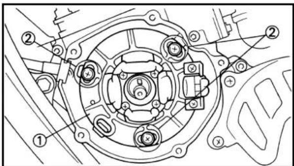
EC4L3000
REMOVAL POINTS
EC4L3102
Rotor
-
Remove:
-
Nut (rotor) ①
- Plain washer ②
Use the rotor holding tool ③.

Rotor holding tool: YU-1235/90890-01235
- Remove:
- Rotor ①
Use the flywheel puller ②.

Flywheel puller: YM-1189/90890-01189
NOTE:
When installing the flywheel puller, turn it counterclockwise.
EC4L4000
INSPECTION
EC4L4101
CDI magneto
-
Inspect:
-
Rotor inner surface ⓐ
- Stator outer surface ⓑ
Damage ->Inspect the crankshaft runout and crankshaft bearing.
If necessary, replace CDI magneto and/or stator.
EC4L4200
Woodruff key
- Inspect:
- Woodruff key ①
Damage →Replace.
EC4L5000
ASSEMBLY AND INSTALLATION
EC4L5172
CDI magneto
- Install:
•Stator ①
- Screw (stator) ②
NOTE:
Temporarily tighten the screw (stator) at this point.
POINTS DE DEPOSE
Rotor
- Déposer:
•Ecrou (rotor) ①
•Rondelle ordinaire ②
•Stator ①
- Vis (stator) ②
N.B.:
•Stator ①
•Schraube (Stator) ②
HINWEIS:
2. Install:
- Woodruff key ①
- Rotor ②
NOTE:
- Clean the tapered portions of the crankshaft and rotor.
- When installing the woodruff key, make sure that its flat surface ③ is in parallel with the crankshaft center line ⑥ .
- When installing the rotor, align the keyway © of the rotor with the woodruff key.

3. Install:
- Plain washer ①
- Nut (rotor) ②
33 Nm (3.3 m•kg, 24 ft•lb)
Use the rotor holding tool ③.

Rotor holding tool: YU-1235/90890-01235
4. Adjust:
- Ignition timing

Ignition timing (B.T.D.C.): 0.52 mm (0.020 in)
Refer to "IGNITION TIMING CHECK" section in the CHAPTER 3.

5. Tighten:
- Screw (stator) ①
9 Nm (0.9 m•kg, 6.5 ft•lb)
6. Check:
- Ignition timing Re-check the ignition timing.
2. Monter:
•Schraube (Stator) ①
9 Nm (0,9 m•kg, 6,5 ft•lb)
6. Kontrollieren:

7. Connect:
- CDI magneto lead ① Refer to “CABLE ROUTING DIAGRAM” section in the CHAPTER 2.
8. Install:
•Gasket [crankcase cover (left)]
•Crankcase cover (left) ①
•Screw [crankcase cover (left)] ②
5 Nm (0.5 m•kg, 3.6 ft•lb)
NOTE:
Tighten the screws in stage, using a crisscross pattern.
7. Connector:
| Extent of removal Order Part name Q'ty Remarks | |||
| Preparation for removal | ENGINE REMOVALHold the machine by placing the suitable stand under the engine.Seat and fuel tankCarburetor Refer to “CARBURETOR AND REED VALVE” section.Exhaust pipe and silencer Refer to “EXHAUST PIPE AND SILENCER” section.Clutch cable Disconnect at engine side.Radiator hose 2 Disconnect at cylinder head side.Radiator hose 4 Disconnect at water pump side.Bolt (radiator) Refer to “RADIATOR” section.Radiator hose 3 Disconnect at right sideSpark plug capDisconnect the CDI magneto lead. | ||
DEPOSE DU MOTEUR
Extent of removal: ①Engine removal
| Extent of removal Order Part name Q'ty Remarks | |||
| 1 | Chain cover 12 Nut (drive sprocket) 13 Lock washer 1 Refer to “REMOVAL POINTS”.4 Drive sprocket 15 Clip 16 Bolt (brake pedal) 17 Brake pedal 18 Engine bracket 29 Engine mounting bolt 310 Pivot shaft11 Engine | 1 | Refer to “REMOVAL POINTS”. |
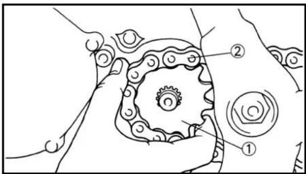

natural_image
Mechanical assembly diagram showing a linkage mechanism with no visible text or symbols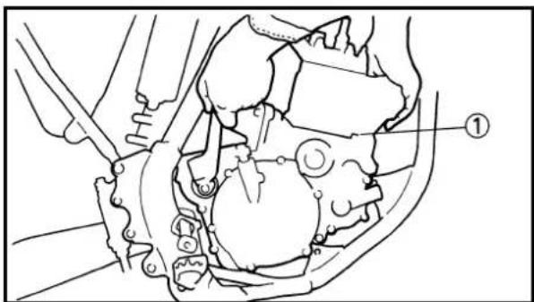
EC4M3000
REMOVAL POINTS
EC4F3100
Drive sprocket
-
Remove:
-
Nut (drive sprocket) ①
- Lock washer ②
NOTE:
• Straighten the lock washer tab.
- Loosen the nut while applying the rear brake.
- Remove:
-Drive sprocket ①
-Drive chain ②
NOTE:
Remove the drive sprocket together with the drive chain.
EC4M3301
Engine removal
- Remove:
- Pivot shaft ①
NOTE:
If the pivot shaft is pulled all the way out, the swingarm will come loose. If possible, insert a shaft of similar diameter into the other side of the swingarm to support it.
- Remove:
-Engine ①
From right side.
NOTE:
Make sure that the couplers, hoses and cables are disconnected.
POINTS DE DEPOSE

EC4M5000
ASSEMBLY AND INSTALLATION
EC4M5171
Engine installation
- Install:
-Engine ①
Install the engine from right side.
- Pivot shaft ②
85 Nm (8.5 m•kg, 61 ft•lb)
•Engine mounting bolt (lower) ③
69 Nm (6.9 m•kg, 50 ft•lb)
•Engine mounting bolt (front) ④
69 Nm (6.9 m•kg, 50 ft•lb)
-Engine bracket ⑤
•Bolt (engine bracket) ⑥
34 Nm (3.4 m•kg, 24 ft•lb)
- CDI unit bracket ⑦
•Engine mounting bolt (upper) ⑧
34 Nm (3.4 m•kg, 24 ft•lb)
NOTE:
Apply the molybdenum disulfide grease on the pivot shaft.
EC4M5211
Brake pedal
- Install:
•Spring ①
-Brake pedal ②
•O-ring ③ New
•Bolt (brake pedal) ④
26 Nm (2.6 m•kg, 19 ft•lb)
- Clip ⑤
NOTE:
- Apply the lithium soap base grease on the bolt, O-rings and brake pedal bracket.
- Install the clip with its stopper portion @facing inward.
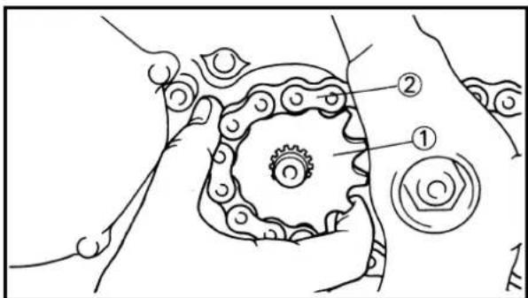
EC4M5311
Drive sprocket
- Install:
-Drive sprocket ①
-Drive chain ②
NOTE:
Install the drive sprocket together with the drive chain.
REMONTAGE ET MONTAGE
Montage du moteur
- Monter:
Tighten the nut while applying the rear brake.
- Bend the lock washer tab to lock the nut.
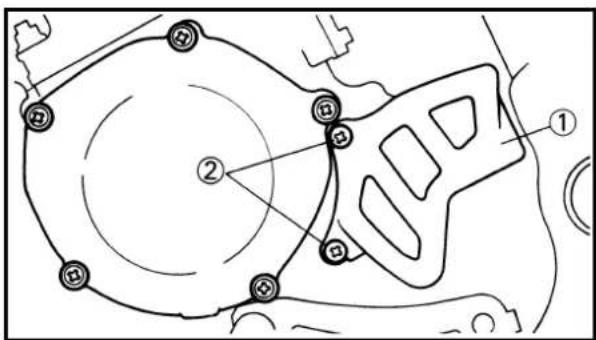
- Install:
- Chain cover ①
- Screw (chain cover) ②

5 Nm (0.5 m•kg, 3.6 ft•lb)
2. Monter:
•Rondelle-frein ①

CRANKCASE AND CRANKSHAFT

Extent of removal:
① Crankcase separation
② Crankshaft removal
③ Crankshaft bearing removal
| Extent of removal Order Part name Q'ty Remarks | ||||
| Preparation for Engine Referto "removal Piston Refer to " | CRANKCASE AND CRANKSHAFT REMOVALPrimary drive gearKick idle gearStopper leverRotor and stator Refer to "CDI MAGNETO" section. | ENGINE REMOVAL" section.CYLINDER HEAD, CYLINDER AND PISTON" section.Refer to "KICK AXLE, SHIFT SHAFT AND PRIMARY DRIVE GEAR" section. | ||
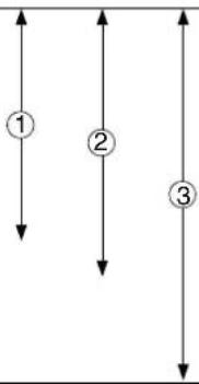 | 1 Segment 1 Refer to "REMOVAL POINTS".2 Bolt [L=50 mm (1.97 in)] 43 Bolt [L=60 mm (2.36 in)] 64 Bolt [L=70 mm (2.76 in)] 25 Holder 16 Crankcase (right) 1 Use special tool.7 Crankcase (left) 1 Refer to "REMOVAL POINTS".8 Crankshaft 1 Use special tool.9 Oil seal Bearing 210 | Refer to "REMOVAL POINTS".2 Refer to "REMOVAL POINTS". | ||

EC4N3000
REMOVAL POINTS
EC4N3100
Segment
-
Remove:
-
Bolt (segment) ①
- Segment ②
NOTE:
Turn the segment counterclockwise until it stops and loosen the bolt.
EC4N3212
Crankcase
- Remove:
•Crankcase (right) ①
Use the crankcase separating tool ②.

Crankcase separating tool: YU-1135-A/90890-01135
NOTE:
- Make appropriate bolts ③as shown available by yourself and attach the tool with them.
- Fully tighten the tool holding bolts, but make sure the tool body is parallel with the case. If necessary, one screw may be backed out slightly to level tool body.
- As pressure is applied, alternately tap on the front engine mounting boss and transmission shafts.
CAUTION:
Use soft hammer to tap on the case half. Tap only on reinforced portions of case. Do not tap on gasket mating surface. Work slowly and carefully. Make sure the case halves separate evenly. If one end "hangs up", take pressure off the push screw, realign, and start over. If the cases do not separate, check for a remaining case screw or fitting. Do not force.
POINTS DE DEPOSE
Segment
- Déposer:
•Boulon (segment) ①
- Segment ②
N.B.:
Make appropriate bolts ③as shown available by yourself and attach the tool with them.
CAUTION:
Do not use a hammer to drive out the crankshaft.

EC4N3401
Crankshaft bearing
- Remove:
•Bearing ①
NOTE:
- Remove the bearing from the crankcase by pressing its inner race as shown in A.
- If the bearing is removed together with the crankshaft, remove the bearing using a general bearing puller ② as shown in [B].
- Do not use the removed bearing.
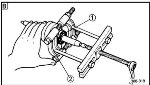
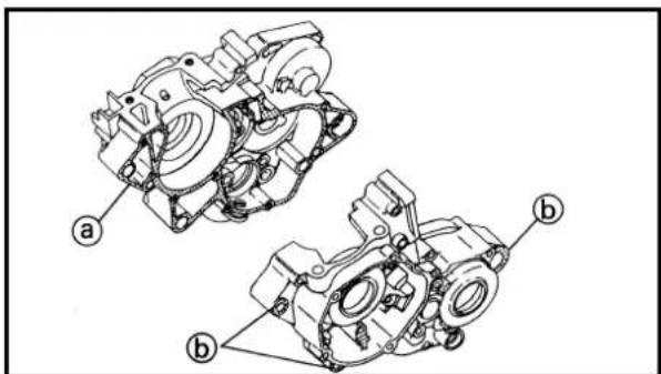
EC4N4000
INSPECTION
EC4N4101
Crankcase
- Inspect:
- Contacting surface @
Scratches →Replace.
- Engine mounting boss ⑥, crankcase
Cracks/Damage →Replace.
Vilebrequin
- Déposer:
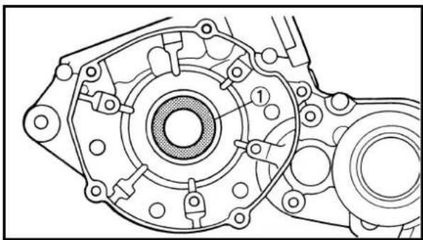
natural_image
Technical line drawing of a mechanical component with no visible text or symbols


2. Inspect:
- Bearings ① Rotate inner race with a finger. Rough spot/Seizure →Replace.
3. Inspect:
- Oil seal ① Damage →Replace.
EC4N4202
Crankshaft
1. Measure:
- Runout limit a - Small end free play limit b - Connecting rod big end side clearance c - Crank width d
Out of specification →Replace. Use the dial gauge and a thickness gauge.
| Dial gauge:YU-3097/90890-01252 |
| Standard | ||
| Runout 0.03 mm 0.05 mm limit: (0.0012 in) (0.0020 in) | ||
| Small end free play: (0.8~1.0 mm 2.0 mm 0.031~0.039 in) (0.08 in) | ||
| Side clearance: (0.20~0.70 (0.008~0.028in) | mm — | |
| Crank width: (2.201~2.203 in) | mm — | |
EC4N5000
ASSEMBLY AND INSTALLATION
EC4N5300
Crankshaft bearing
1. Install:
- Bearing ① New To crankcase (left and right).
NOTE:
Install the bearing by pressing its outer race parallel.
CARTER ET VILEBREQUIN KURBELGEHÄUSE UND KURBELWELLE CARTER E ALBERO A GOMITI
ENG
2. Examiner:
EC4N5102
Oil seal
- Install:
•Oil seal (left) ① New
•Oil seal (right) ② New
NOTE:
- Apply the lithium soap base grease on the oil seal lip.
- Install the oil seal with its manufacture's marks or numbers facing outward.

EC4N5272
Crankshaft
- Install:
•Crankshaft ①
Use the crankshaft installing tool ②, ③, ④

Crankshaft installing tool:
Pot ②:② YU-90050/90890-01274
Bolt ③ YU-90050/90890-01275
Adapter ④:4YU-90062/90890-01277
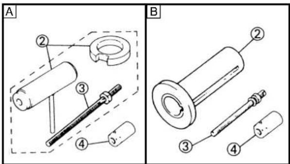
A For USA and CDN
B Except for USA and CDN
NOTE:
- Hold the connecting rod at top dead center with one hand while turning the nut of the installing tool with the other. Operate the installing tool until the crankshaft bottoms against the bearing.
- Before installing the crankshaft, clean the contacting surface of crankcase.
- Apply the lithium soap base grease on the oil seal lip.
CAUTION:
Do not use a hammer to drive in the crankshaft.
Bague d'étanchéité
- Monter:
natural_image
Mechanical assembly diagram showing gear and shaft components with no visible text or symbols
2. Check:
- Shifter operation
•Transmission operation
Unsmooth operation → Repair.
3. Apply:
- Sealant
On the crankcase (right) ①

Quick gasket®:
ACC-QUICK-GS-KT
Yamaha bond No. 1215:
90890-85505
NOTE:
Clean the contacting surface of crankcase (left and right) before applying the sealant.


4. Install:
- Dowel pin ①
•O-ring ② New
•Crankcase (right) ③
To crankcase (left) ④.
NOTE:
- Fit the crankcase (right) onto the crankcase (left). Tap lightly on the case with soft hammer.
- When installing the crankcase, the connecting rod should be positioned at TDC (top dead center).
5. Install:
- Clamp ①
- Bolt (crankcase) ②
14 Nm (1.4 m•kg, 10 ft•lb)
NOTE:
Tighten the crankcase tightening bolts in stage, using a crisscross pattern.
CARTER ET VILEBREQUIN KURBELGEHÄUSE UND KURBELWELLE CARTER E ALBERO A GOMITI
ENG

2. Contrôler:
•Bride ①
•Boulon (carter) ②
14 Nm (1,4 m•kg, 10 ft•lb)
N.B.:
•Brida ①
•Bullone (carter) ②
14 Nm (1,4 m•kg, 10 ft•lb)
NOTA:


6. Install:
- Holder ①
•Bolt (holder) ②


10 Nm (1.0 m•kg, 7.2 ft•lb)
7. Install:
- Segment ①
- Bolt (segment) ②

30 Nm (3.0 m•kg, 22 ft•lb)
NOTE:
- When installing the segment onto the shift cam ③, align the punch mark ⓐ with the dowel pin ⑥.
- Turn the segment clockwise until it stops and tighten the bolt.
8. Remove:
- Sealant
Forced out on the cylinder mating surface.
9. Apply:
- Engine oil
To the crank pin, bearing, oil delivery hole and connecting rod big end washer.
10. Check:
- Crankshaft and transmission operation Unsmooth operation → Repair.
6. Monter:
•Support ①
•Boulon (support) ②


10 Nm (1,0 m•kg, 7,2 ft•lb)
6. Einbauen:
•Halter ①
•Schraube (Halter) ②


10 Nm (1,0 m•kg, 7,2 ft•lb)
6. Installare:
- Segment ①
•Boulon (segment) ②

30 Nm (3,0 m•kg, 22 ft•lb)
N.B.:
TRANSMISSION, SHIFT CAM AND SHIFT FORK

Extent of removal:
① Shift cam and shift fork removal
② Main axle and drive axle removal
| Extent of removal Order | Name Q'ty Remarks | ||||
| Preparation for Engine removal Separate the | TRANSMISSION, SHIFT CAM AND SHIFT FORK REMOVALRefer to “crankcase. Refer to | ENGINE REMOVAL” section.“CRANKCASE AND CRANK SHAFT” section. | |||
 | 1 Guide bar (long) 12 Guide bar (short) 13 Shift cam 14 Shift fork 3 15 Shift fork 1 16 Shift fork 2 17 Main axle 18 Drive axle 19 Spacer | Refer to “REMOVAL POINTS”. | |||
BOITE A VITESSES, BARILLET DE SELECTEUR ET FOURCHETTE GETRIEBE, SCHALTNOCKE UND SCHALTGABEL TRASMISSIONE, CAMMA DEL CAMBIO E FORCELLA DEL CAMBIO
ENG
BOITE A VITESSES, BARILLET DE SELECTEUR ET FOURCHETTE
EC4H3000
REMOVAL POINTS
EC4H3200
Transmission
-
Remove:
-
Main axle ①
-Drive axle ②
NOTE:
- Tap lightly on the transmission drive axle with a soft hammer to remove.
- Remove assembly carefully. Note the position of each part. Pay particular attention to the location and direction of shift forks.

EC4H4000
INSPECTION
EC4H4200
Gears
-
Inspect:
-
Matching dog ⓐ
•Gear teeth ⓑ - Shift fork groove ©
Wear/Damage >Replace.

natural_image
Technical line drawing of a mechanical gear assembly (no text or symbols)- Check:
•Gears movement
Unsmooth movement →
Repair or replace.
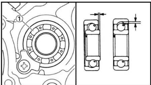
EC4H4600
Bearing
- Inspect:
•Bearing ①
Rotate inner race with a finger.
Rough spot/Seizure >Replace.
BOITE A VITESSES, BARILLET DE SELECTEUR ET FOURCHETTE GETRIEBE, SCHALTNOCKE UND SCHALTGABEL TRASMISSIONE, CAMMA DEL CAMBIO E FORCELLA DEL CAMBIO
ENG

POINTS DE DEPOSE
Boîte à vitesses

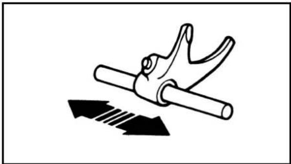
natural_image
Diagram of a hand gripping a cylindrical object with two arrows indicating force or movement (no text or symbols)
EC4H4801
Shift fork, shift cam and segment
- Inspect:
- Shift fork ① Wear/Damage/Scratches →Replace.
- Inspect:
- Shift cam ① - Segment ② - Guide bar ③ Bend/Wear/Damage >Replace.
- Check:
- Shift fork movement On its guide bar. Unsmooth operation →Replace shift fork and/or guide bar.
NOTE:
For a malfunctioning shift fork, replace not only the shift fork itself but the two gears each adjacent to the shift fork.
EC4H5000
ASSEMBLY AND INSTALLATION
EC4H5213
Transmission
- Install:
- 5th pinion gear (23T) ① - 3rd pinion gear (19T) ② - 4th pinion gear (19T) ③ - 2nd pinion gear (15T) ④ To main axle ⑤.
NOTE:
- Apply the molybdenum disulfide oil on the 4th and 5th pinion gears inner circumference and on the end surface. - Apply the molybdenum disulfide oil on the 2nd and 3rd pinion gears inner circumference.
BOITE A VITESSES, BARILLET DE SELECTEUR ET FOURCHETTE GETRIEBE, SCHALTNOCKE UND SCHALTGABEL TRASMISSIONE, CAMMA DEL CAMBIO E FORCELLA DEL CAMBIO
ENG

2. Install:
- 3rd wheel gear (29T) ①
•4th wheel gear (24T) ② - 2nd wheel gear (28T) ③
- 5th wheel gear (25T) ④
- 1st wheel gear (30T) ⑤
To drive axle ⑥.
NOTE:
- Apply the molybdenum disulfide oil on the 1st, 2nd and 3rd wheel gears inner circumference and on the end surface.
- Apply the molybdenum disulfide oil on the 4th and 5th wheel gears inner circumference.

3. Install:
- Plain washer ①
• Circlip ② New
NOTE:
- Be sure the circlip sharp-edged corner Ⓐis positioned opposite side to the plain washer and gear ⓑ.
- Be sure the circlip end Ⓒis positioned at axle spline groove ⓐ.

natural_image
Technical line drawing of a gear assembly (left) and a mechanical component with labeled parts (right), no text or symbols present.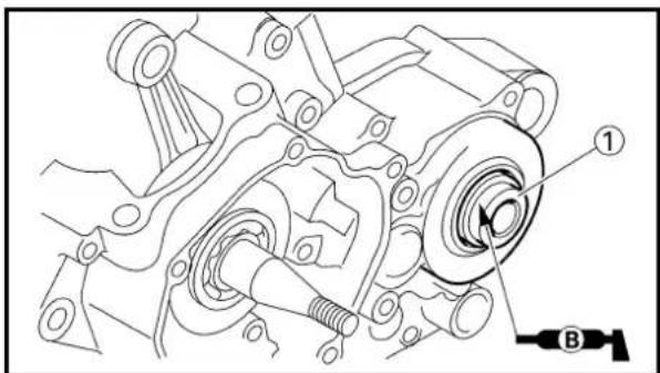
4. Install:
- Spacer ①
NOTE:
- Apply the lithium soap base grease on the oil seal lip.
- When installing the spacer into the crankcase, pay careful attention to the crankcase oil seal lip.
BOITE A VITESSES, BARILLET DE SELECTEUR ET FOURCHETTE GETRIEBE, SCHALTNOCKE UND SCHALTGABEL TRASMISSIONE, CAMMA DEL CAMBIO E FORCELLA DEL CAMBIO
ENG

2. Monter:


5. Install:
- Main axle ①
-Drive axle ②
NOTE:
Apply the transmission oil on the crankcase bearings.
EC4H5312
Shift cam and shift fork
1. Install:
- Shift fork 1 (L) ①
- Shift fork 2 (C) ②
- Shift fork 3 (R) ③
NOTE:
- Mesh the shift fork #1 (L) with the 4th wheel gear ④ and #3 (R) with the 5th wheel gear ⑥ on the drive axle.
- Mesh the shift fork #2 (C) with the 3rd pinion gear ⑤ on the main axle.
2. Install:
- Shift cam ①
NOTE:
- Apply the transmission oil on the shift cam.
- Install the shift cam while holding up the 4th wheel gear ② and keeping the shift fork #1 ③ moved in the direction of the arrow.
3. Install:
•Guide bar (short) ①
•Guide bar (long) ②
NOTE:
- Apply the transmission oil on the guide bars.
- Be sure the long bar is inserted into the shift forks #1 and #3 and the short one into #2.
BOITE A VITESSES, BARILLET DE SELECTEUR ET FOURCHETTE GETRIEBE, SCHALTNOCKE UND SCHALTGABEL TRASMISSIONE, CAMMA DEL CAMBIO E FORCELLA DEL CAMBIO
ENG
5. Monter:
- Axe principal ①
- Axe motcur ②
N.B.:
natural_image
Mechanical assembly diagram showing gear and shaft components with no visible text or symbols4. Check:
- Shifter operation
•Transmission operation
Unsmooth operation → Repair.
BOITE A VITESSES, BARILLET DE SELECTEUR ET FOURCHETTE GETRIEBE, SCHALTNOCKE UND SCHALTGABEL TRASMISSIONE, CAMMA DEL CAMBIO E FORCELLA DEL CAMBIO
ENG
4. Contrôler:
① Front wheel removal
② Wheel bearing removal
③ Brake disc removal
| Extent of removal Order Part name Q'ty Remarks | |||
| Preparation for removal | FRONT WHEEL REMOVALHold the machine by placing the suitable stand under the engine. | ||
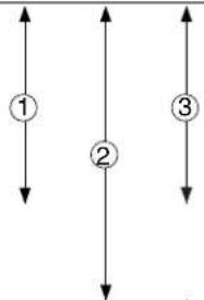 3 3 | 1 Hose cover 12 Bolt (brake hose holder) 2 Only loosening.3 Bolt (axle holder) 4 Only loosening.4 Nut (front wheel axle) 15 Front wheel axle 16 Front wheel 17 Collar 28 Oil seal 29 Bearing 2 Refer to “REMOVAL POINTS”.10 Brake disc 1 | ||
PARTIE CYCLE
ROUE AVANT ET ROUE ARRIERE
ROUE AVANT
Etendue de dépose:
① Rear wheel removal
② Wheel bearing removal
③ Brake disc removal
| Extent of removal Order Part name Q'ty Remarks | |||||
| Preparation for removal | REAR WHEEL REMOVALHold the machine by placing the suitable stand under the engine. | ▲WARNINGSupport the machine securely so there is no danger of it falling over. | |||
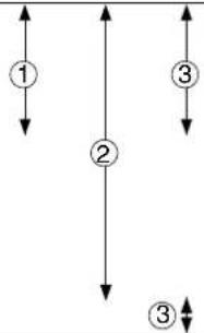 | 1 Nut (rear wheel axle) 12 Rear wheel axle 13 Chain puller 24 Rear wheel 1 Refer to “REMOVAL POINTS”.5 Collar 26 Driven sprocket 17 Oil seal 28 Circlip9 Bearing10 Brake disc | ||||
| 12 Refer to “REMOVAL POINTS”.1 | |||||
ROUE ARRIERE
Etendue de dépose:
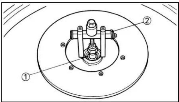
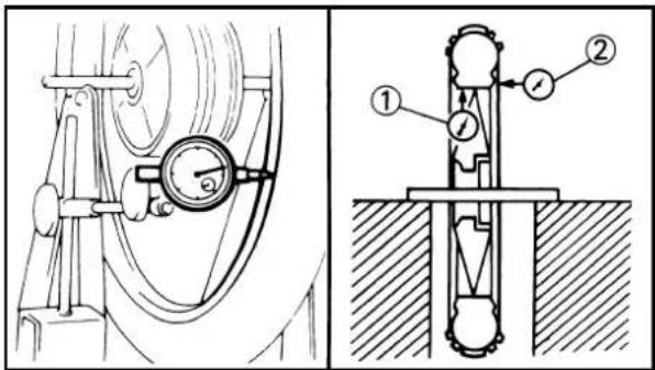

natural_image
Technical line drawing of two mechanical bearing assemblies with no visible text or symbolsEC593000
REMOVAL POINTS
EC523101
Rear wheel
- Remove:
- Wheel ①
NOTE:
Push the wheel forward and remove the drive chain ②.
EC513201
Wheel bearing (if necessary)
- Remove:
•Bearing ①
NOTE:
Remove the bearing using a general bearing puller ②.
EC594000
INSPECTION
EC514100
Wheel
- Measure:
- Wheel runout
Out of limit→Repair/Replace.

Wheel runout limit:
Radial ①:2.0mm (0.08 in)
Lateral ②:2.0mm (0.08 in)
- Inspect:
•Bearing
Rotate inner race with a finger.
Rough spot/Seizure →Replace.
NOTE:
Replace the bearings, oil seal and wheel collar as a set.
POINTS DE DEPOSE
Roue arrière
- Déposer:
•Roue ①
N.B.:
EC514200
Wheel axle
- Measure:
- Wheel axle bends
Out of specification →Replace.
Use the dial gauge ①.

Wheel axle bending limit: 0.5 mm (0.020 in)
NOTE:
The bending value is shown by one half of the dial gauge reading.
WARNING
Do not attempt to straighten a bent axle.

EC594200
Brake disc
- Measure:
- Brake disc deflection (only rear brake disc) Use the dial gauge ①.
Out of specification→Inspect wheel runout.
If wheel runout is in good condition, replace the brake disc.
| Disc deflection limit: | ||
| Standard | ||
| Rear | — | 0.15 mm (0.006 in) |
- Measure:
- Brake disc thickness ⓐ
Out of limit →Replace.
| Disc wear limit: | ||
| Standard | ||
| Front | 3.0 mm (0.12 in) 2.5 | mm (0.10 in) |
| Rear | 4.0 mm (0.16 in) 3.5 | mm (0.14 in) |
ROUE AVANT ET ROUE ARRIERE VORDERRAD UND HINTERRAD RUOTA ANTERIORE E RUOTA POSTERIORE

Axe de roue
- Mesurer:
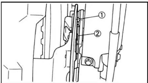
EC595000
ASSEMBLY AND INSTALLATION
EC595101
Front wheel
- Install:
•Bearing (left) ①
- Spacer ②
•Bearing (right) ③
- Oil seal ④ New
NOTE:
- Apply the lithium soap base grease on the bearing and oil seal lip when installing.
- Use a socket that matches the outside diameter of the race of the bearing.
- Left side of bearing shall be installed first.
- Install the oil seal with its manufacture's marks or numbers facing outward.
CAUTION:
Do not strike the inner race of the bearing. Contact should be made only with the outer race.
- Install:
-Brake disc ①
•Bolt (brake disc) ②

12 Nm (1.2 m•kg, 8.7 ft•lb)
NOTE:
Tighten the bolts in stage, using a crisscross pattern.
- Install:
•Collar ①
NOTE:
-
Apply the lithium soap base grease on the oil seal lip.
• Install the collars with their projections @facing the wheel. -
Install:
•Wheel
NOTE:
Install the brake disc ①between the brake pads ②correctly.
REMONTAGE ET MONTAGE
Roue avant
- Monter:

natural_image
Technical line drawing of a mechanical assembly with hands and a numbered component (no text or symbols)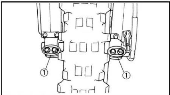

natural_image
Mechanical diagram showing a lever mechanism with gear and pulley components (no text or labels)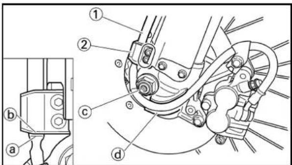
- Install:
- Wheel axle ①
NOTE:
Apply the lithium soap base grease on the wheel axle.
- Install:
•Nut (wheel axle) ①
105 Nm (10.5 m•kg, 75 ft•lb)
- Tighten:
•Bolt (axle holder) ①
23 Nm (2.3 m·kg, 17 ft·lb)
NOTE:
Before tightening the bolt, fit the wheel axle to the axle holder by stroking the front fork several times with the front brake applied.
- Install:
-Brake hose ①
10 Nm (1.0 m•kg, 7.2 ft•lb)
To brake hose holder ②.
NOTE:
Before tightening the bolt (brake hose holder), align the top ⓐ of the brake hose neck with the brake hose holder bottom ⓑ. Then pass the brake hose in front of the axle boss ⓒ and fit it into the hose groove ⓔ so that the brake hose does not contact the nut (wheel axle).
ROUE AVANT ET ROUE ARRIERE VORDERRAD UND HINTERRAD RUOTA ANTERIORE E RUOTA POSTERIORE

5. Monter:
- Axe de roue ①
N.B.:
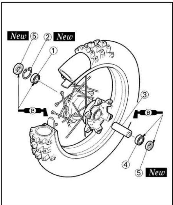
9. Install:
•Hose cover ①
- Plain washer ②
•Bolt [hose cover (M8)] ③
16 Nm (1.6 m•kg, 11 ft•lb)
•Bolt [hose cover (M6)] ④
7 Nm (0.7 m•kg, 5.1 ft•lb)
EC5251A1
Rear wheel
1. Install:
•Bearing (right) ①
•Circlip ② New
- Spacer ③
•Bearing (left) ④
- Oil seal ⑤ New
NOTE:
- Apply the lithium soap base grease on the bearing and oil seal lip when installing.
•Install the bearing with seal facing outward. - Use a socket that matches the outside diameter of the race of the bearing.
•Right side of bearing shall be installed first. - Install the oil seal with its manufacture's marks or numbers facing outward.
CAUTION:
Do not strike the inner race of the bearing. Contact should be made only with the outer race.

2. Install:
-Brake disc ①
- Bolt (brake disc) ②

14 Nm (1.4 m•kg, 1.0 ft•lb)
NOTE:
Tighten the bolts in stage, using a crisscross pattern.
ROUE AVANT ET ROUE ARRIERE VORDERRAD UND HINTERRAD RUOTA ANTERIORE E RUOTA POSTERIORE

9. Monter:
•Couvercle de tuyau ①
•Rondelle ordinaire ②
•Boulon

natural_image
Technical line drawing of a mechanical gear assembly with a hand adjusting a shaft (no text or symbols)
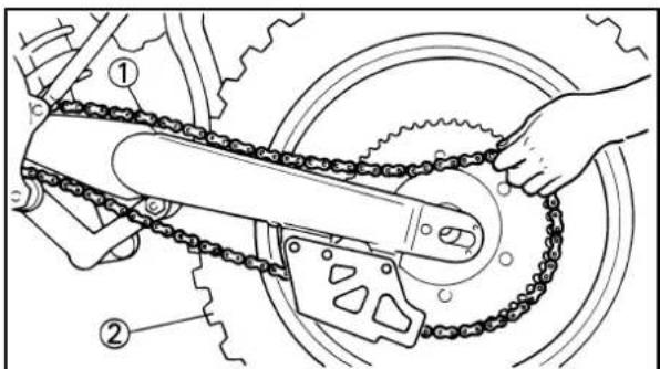

3. Install:
- Driven sprocket ①
•Bolt (driven sprocket) ② - Plain washer (driven sprocket) ③
•Nut (driven sprocket) ④
42 Nm (4.2 m•kg, 30 ft•lb)
NOTE:
Tighten the nuts in stage, using a crisscross pattern.
4. Install:
•Collar ①
NOTE:
Apply the lithium soap base grease on the oil seal lip.
5. Install:
•Wheel
NOTE:
Install the brake disc ①between the brake pads ②correctly.
6. Install:
-Drive chain ①
NOTE:
Push the wheel ②forward and install the drive chain.
7. Install:
- Chain puller (left) ①
- Wheel axle ②
NOTE:
• Install the chain puller (left), and insert the wheel axle from left side.
- Apply the lithium soap base grease on the wheel axle.
3. Monter:

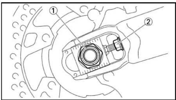
8. Install:
- Chain puller (right) ①
- Plain washer ②
- Nut (wheel axle) ③
NOTE:
Temporarily tighten the nut (wheel axle) at this point.
9. Adjust:
-Drive chain slack ⓐ

Drive chain slack : 40\~50 mm (1.6\~2.0 in)
Refer to "DRIVE CHAIN SLACK ADJUSTMENT" section in the CHAPTER 3.
10. Tighten:
- Nut (wheel axle) ①
- Locknut ②
125 Nm (12.5 m•kg, 90 ft•lb)
16 Nm (1.6 m•kg, 11 ft•lb)
ROUE AVANT ET ROUE ARRIERE VORDERRAD UND HINTERRAD RUOTA ANTERIORE E RUOTA POSTERIORE

8. Monter:
① Brake hose removal
② Caliper removal
③ Master cylinder removal
| Extent of removal Order Part name Q'ty Remarks | ||||
| Preparation for removal | FRONT BRAKE REMOVALHold the machine by placing the suitable stand under the engine.Drain the brake fluid. Refer to “REMOVAL POINTS”. | |||
 | 1 Hose cover 12 Brake hose holder 13 Bolt (brake hose holder) 2 Only loosening.4 Union bolt 25 Brake hose 16 Pad pin plug 17 Pad pin 18 Caliper 19 Brake lever 110 Master cylinder bracket 111 Master cylinder 1 | Remove when loosening the pad pin.Loosen when disassembling the caliper. | ||
FREIN AVANT ET FREIN ARRIERE
FREIN AVANT
Etendue de dépose:
① Master cylinder removal
② Brake hose removal
③ Caliper removal
| Extent of removal Order Part name Q'ty Remarks | |||
| Preparation for removal | REAR BRAKE REMOVALHold the machine by placing the suitable stand under the engine.Rear wheel Refer to “FRONT WHEEL ANDDrain the brake fluid. Refer to “REMOVAL POINTS”. | ▲WARNINGSupport the machine securely so there is no danger of it falling over. | |
 1◀ [KABC] 1◀ [KABC]  [7WOK] [7WOK] | 1 Brake pedal 12 Master cylinder 13 Brake hose holder 24 Union bolt 25 Brake hose 16 Pad pin plug 17 Pad pin 18 Caliper 1 | REAR WHEEL” section.REMOVAL POINTS”.Remove when loosening the pad pin.Loosen when disassembling the caliper. | |
FREIN ARRIERE
Etendue de dépose:
① Front caliper disassembly
② Rear caliper disassembly
| Extent of removal Order Part name Q'ty Remarks | ||||
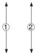 | CALIPER DISASSEMBLY A B1Pad pin 1 12Brake pad 2 23Pad support 1 14Caliper piston 2 1 Refer to “REMOVAL POINTS”.5Dust seal 2 16Piston seal 2 1 | Refer to “REMOVAL POINTS”. | ||
DEMONTAGE DE L'ETRIER
A Avant
B Arrière
Etendue de dépose:
① Front master cylinder disassembly
② Rear master cylinder disassembly
| Extent of removal Order Part name Q'ty Remarks | |||
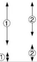 | MASTER CYLINDER DISASSEMBLY1Master cylinder cap 12Diaphragm 13Master cylinder boot 14Circlip 1 Use a long nose circlip pliers.5Plain washer 16Push rod 17Master cylinder kit 1 | ||
DEMONTAGE DU MAITRE-CYLINDRE
A Avant
B Arrière
Etendue de dépose:
natural_image
Technical line drawing of a mechanical assembly with springs and clamps (no text or symbols)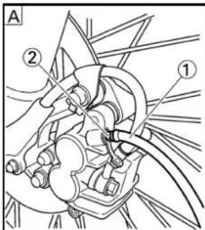
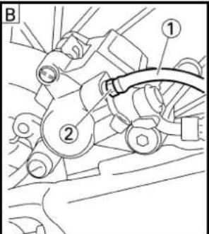
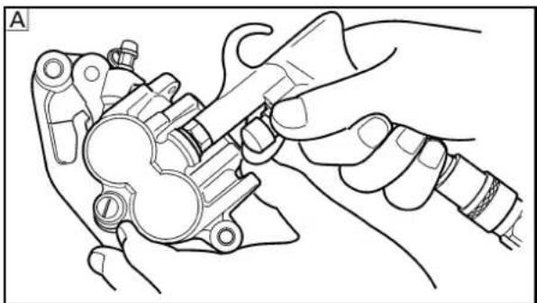
natural_image
Line drawing of hands assembling a mechanical component (no text or symbols)
natural_image
Line drawing of hands using a tool to adjust or install a mechanical component (no text or symbols present)EC5A3000
REMOVAL POINTS
EC5A3101
Brake fluid
- Remove:
[Front]
•Master cylinder cap ①
[Rear]
- Master cylinder cap ①
•Protector
NOTE:
Do not remove the diaphragm.

Front

Rear
- Connect the transparent hose ① to the bleed screw ② and place a suitable container under its end.

Front

Rear
- Loosen the bleed screw and drain the brake fluid while pulling the lever in or pushing down on the pedal.
CAUTION:
- Do not reuse the drained brake fluid.
- Brake fluid may erode painted surfaces or plastic parts. Always clean up spilled fluid immediately.
EC533301
Caliper piston
- Remove:
- Caliper piston
Use compressed air and proceed carefully.
WARNING
• Cover piston with rag and use extreme caution when expelling piston from cylinder.
•Never attempt to pry out piston.
Caliper piston removal steps:
- Insert a piece of rag into the caliper to lock one caliper.
- Carefully force the piston out of the caliper cylinder with compressed air.

Front

Rear
POINTS DE DEPOSE
Liquide de frein
- Déposer:
[Avant]

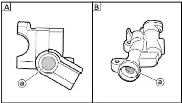
natural_image
Technical drawings of mechanical parts labeled A and B, showing cross-sectional views with no visible text or symbols.
natural_image
Technical diagrams of mechanical components labeled A and B, showing cross-sectional views with no visible text or symbols.
EC533402
Piston seal kit
-
Remove:
-
Dust seal ①
•Piston seal ②
NOTE:
Remove the piston seals and dust seals by pushing them with a finger.
CAUTION:
Never attempt to pry out piston seals and dust seals.
WARNING
Replace the piston seals and dust seals whenever a caliper is disassembled.
A Front
B Rear
EC5A4000
INSPECTION
EC534112
Master cylinder
- Inspect:
•Master cylinder inner surface ⓐ
Wear/Scratches→Replace master cylinder assembly.
Stains→Clean.
WARNING
Use only new brake fluid.
A Front
B Rear
- Inspect:
•Diaphragm ①
Crack/Damage >Replace.
A Front
B Rear
-
Inspect:
-
Master cylinder piston ①
•Master cylinder cup ②
Wear/Damage/Score marks→Replace master cylinder kit.
A Front
B Rear
FREIN AVANT ET FREIN ARRIERE VORDERRADBREMSE UND HINTERRADBREMSE FRENO ANTERIORE E FRENO POSTERIORE

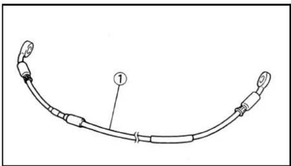
natural_image
Line drawing of a curved cable or connector with labeled component (1), no text or symbols presentEC534214
Caliper
- Inspect:
- Caliper cylinder inner surface ⓐ Wear/Score marks→Replace caliper assembly.
A Front
B Rear
- Inspect:
- Caliper piston ① Wear/Score marks →Replace caliper piston assembly.
WARNING
Replace the piston seals and dust seals ②② whenever a caliper is disassembled.
EC534301
Brake hose
- Inspect:
- Brake hose ① Crack/Damage→Replace.
EC5A5000
ASSEMBLY AND INSTALLATION
WARNING
- All internal parts should be cleaned in new brake fluid only.
- Internal parts should be lubricated with brake fluid when installed.
-Replace the piston seals and dust seals whenever a caliper is disassembled.
EC5A5801
Caliper piston
- Clean:
•Caliper
- Piston seal
•Dust seal
- Caliper piston
Clean them with brake fluid.
Etrier
- Examiner:


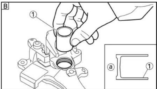
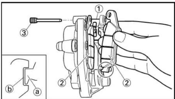
- Install:
•Piston seal ①
New
•Dust seal ②
New
WARNING
Always use new piston seals and dust seals.
NOTE:
Fit the piston seals and dust seals onto the slot on caliper correctly.

Front
Rear
- Install:
- Caliper piston ①
NOTE:
Apply the brake fluid on the piston wall.
CAUTION:
• Install the piston with its shallow depressed side @ facing the caliper.
- Never force to insert.

Front
Rear
EC5A5700
Front caliper
- Install:
- Pad support ①
-Brake pad ②
- Pad pin ③
NOTE:
• Install the brake pads with their projections Ⓐ into the caliper recesses ⓑ.
•Temporarily tighten the pad pin at this point.
FREIN AVANT ET FREIN ARRIERE VORDERRADBREMSE UND HINTERRADBREMSE FRENO ANTERIORE E FRENO POSTERIORE

- Monter:
•Joint de piston ①
New
•Joint antipoussière ②
New
⚠ AVERTISSEMENT
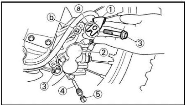
- Install:
•Copper washer ①
New
- Union bolt ②
30 Nm (3.0 m•kg, 22 ft•lb)
WARNING
Always use new copper washers.
CAUTION:
Install the brake hose so that its pipe portion a directs as shown and lightly touches the projection b on the caliper.
-
Install:
-
Brake hose holder ①
- Caliper ②
- Bolt (caliper) ③
23 Nm (2.3 m•kg, 17 ft•lb)
NOTE:
Fit the brake hose holder cut ⓐ over the projection Ⓐ on the front fork and clamp the brake hose.
- Tighten:
- Pad pin ④
18 Nm (1.8 m•kg, 13 ft•lb)
- Install:
- Pad pin plug ⑤
3 Nm (0.3 m•kg, 2.2 ft•lb)
EC5A5121
Rear caliper
-
Install:
-
Pad support ①
-Brake pad ② - Pad pin ③
NOTE:
• Install the brake pads with their projections
Ⓐ into the caliper recesses ⓑ.
•Temporarily tighten the pad pin at this point.
FREIN AVANT ET FREIN ARRIERE VORDERRADBREMSE UND HINTERRADBREMSE FRENO ANTERIORE E FRENO POSTERIORE
2. Monter:

2. Install:
- Disc cover ①
•Bolt (disc cover) ②
7 Nm (0.7 m•kg, 5.1 ft•lb)
3. Install:
- Caliper ①
•Rear wheel ②
Refer to "FRONT WHEEL AND REAR WHEEL" section.
4. Tighten:
- Pad pin ③
18 Nm (1.8 m•kg, 13 ft•lb)
5. Install:
- Pad pin plug ④
3 Nm (0.3 m•kg, 2.2 ft•lb)
EC5A5220
Master cylinder kit
1. Clean:
- Master cylinder
- Master cylinder kit
Clean them with brake fluid.


2. Install:
•Master cylinder cup (primary) ①
•Master cylinder cup (secondary) ②
To master cylinder piston ③.
NOTE:
Apply the brake fluid on the master cylinder cup.
WARNING
After installing, cylinder cup should be installed as shown direction. Wrong installation cause improper brake performance.

Front
Rear
FREIN AVANT ET FREIN ARRIERE VORDERRADBREMSE UND HINTERRADBREMSE FRENO ANTERIORE E FRENO POSTERIORE

2. Monter:


3. Install:
- Spring ①
To master cylinder piston ②.
NOTE:
Install the spring at the smaller dia. side.

Front

Rear
4. Install:
[Front]
- Master cylinder kit ①
- Plain washer ②
• Circlip ③
•Master cylinder boot ④
To master cylinder ⑤.
[Rear]
- Master cylinder kit ①
- Push rod ②
• Circlip ③ - Master cylinder boot ④
To master cylinder ⑤.
NOTE:
- Apply the brake fluid on the master cylinder kit.
- Apply the lithium soap base grease on the tip of the push rod.
- When installing the circlip, use a long nose circlip pliers.

Front

Rear
EC5A5310
Front master cylinder
1. Install:
- Master cylinder ①
- Master cylinder bracket ②
•Bolt (master cylinder bracket) ③
9 Nm (0.9 m•kg, 6.5 ft•lb)
NOTE:
• Install the bracket so that the arrow mark ⓐ face upward.
- First tighten the bolts on the upper side of the master cylinder bracket, and then tighten the bolts on the lower side.
FREIN AVANT ET FREIN ARRIERE VORDERRADBREMSE UND HINTERRADBREMSE FRENO ANTERIORE E FRENO POSTERIORE
3. Monter:
•Ressort ①
2. Install:
- Brake lever ①
•Bolt (brake lever) ②
6 Nm (0.6 m•kg, 4.3 ft•lb)
- Nut (brake lever) ③
6 Nm (0.6 m•kg, 4.3 ft•lb)
NOTE:
Apply the lithium soap base grease on the brake lever sliding surface, bolt and contacting surface of the master cylinder piston.
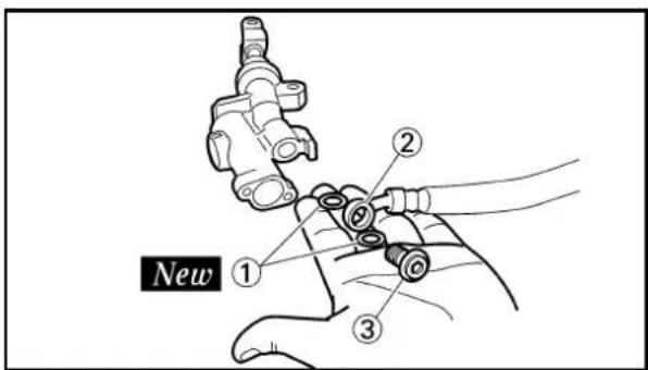
EC5A5401
Rear master cylinder
- Install:
•Copper washer ①
New
- Brake hose ②
- Union bolt ③
30 Nm (3.0 m•kg, 22 ft•lb)

WARNING
Always use new copper washers.
CAUTION:
Install the brake hose so that its pipe portion a directs as shown and lightly touches the projection b on the master cylinder.
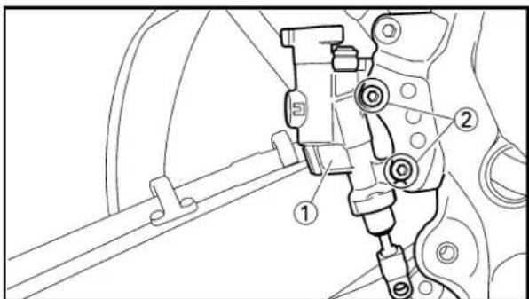
-
Install:
-
Master cylinder ①
•Bolt (master cylinder) ②
10 Nm (1.0 m•kg, 7.2 ft•lb)
FREIN AVNAT ET FREIN ARRIERE VORDERRADBREMSE UND HINTERRADBREMSE FRENO ANTERIORE E FRENO POSTERIORE

2. Monter:
•Mutter (Bremshebel) ③

HINWEIS:
•Spring ①
- Brake pedal ②
•O-ring ③ New
•Bolt (brake pedal) ④
26 Nm (2.6 m•kg, 19 ft•lb)
•Clip ⑤
NOTE:
- Apply the lithium soap base grease on the bolt, O-ring and brake pedal bracket.
- Install the clip with its stopper portion @facing inward.

4. Install:
•Pin ①
- Plain washer ②
•Cotter pin ③ New
NOTE:
After installing, check the brake pedal height. Refer to "REAR BRAKE ADJUSTMENT" section in the CHAPTER 3.
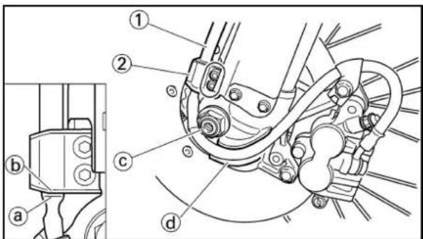
EC5A5911
Front brake hose
1. Install:
-Brake hose ①
10 Nm (1.0 m•kg, 7.2 ft•lb)
To brake hose holder ②.
NOTE:
Before tightening the bolt (brake hose holder), align the top ⓐ of the brake hose neck with the brake hose holder bottom ⓑ. Then pass the brake hose in front of the axle boss ⓒ and fit it into the hose groove ⓔ so that the brake hose does not contact the nut (wheel axle).

2. Install:
•Hose cover ①
- Plain washer ②
•Bolt [hose cover (M8)] ③
16 Nm (1.6 m•kg, 11 ft•lb)
•Bolt [hose cover (M6)] ④
7 Nm (0.7 m•kg, 5.1 ft•lb)
3. Monter:
- Pass the brake hose through the cable guide ①, then through the guide ④ on the protector ②.
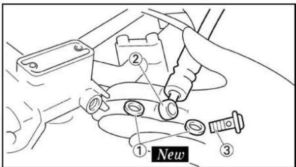
- Install:
•Copper washer ①
New
-Brake hose ②
- Union bolt ③
30 Nm (3.0 m•kg, 22 ft•lb)
WARNING
Always use new copper washers.
CAUTION:
Install the brake hose so that its pipe portion a directs as shown and lightly touches the projection b on the master cylinder.


EC5A5502
Rear brake hose
- Install:
•Copper washer ①
New
- Brake hose ②
- Union bolt ③
30 Nm (3.0 m•kg, 22 ft•lb)
WARNING
Always use new copper washers.
CAUTION:
Install the brake hose so that its pipe portion a directs as shown and lightly touches the projection b on the caliper.

FREIN AVANT ET FREIN ARRIERE VORDERRADBREMSE AND HINTERRADBREMSE FRENO ANTERIORE E FRENO POSTERIORE

-
Faire passer la tuyau de frein dans le guide de câble ①, puis dans le guide ④ sur le protecteur ②.
-
Den Bremsschlauch durch die Kabelführung ① und danach durch die Führung ② am Schutz ② führen.
-
Far passare il tubo flessibile del freno attraverso la guida per cavi ①, quindi attraverso la guida ④ sul dispositivo di protezione ②.
-
Monter:

natural_image
Line drawing of a vehicle's wheel and gear assembly (no text or symbols)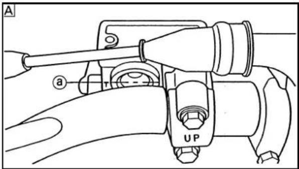

2. Install:
- Brake hose holder ①
•Screw (brake hose holder) ②
1 Nm (0.1 m•kg, 0.7 ft•lb)
CAUTION:
After installing the brake hose holders, make sure the brake hose does not contact the spring (rear shock absorber). If it does, correct its twist.
EC5A5601
Brake fluid
1. Fill:
-Brake fluid
Until the fluid level reaches "LOWER" level line ⓐ.

Recommended brake fluid: DOT #4
WARNING
- Use only the designated quality brake fluid: otherwise, the rubber seals may deteriorate, causing leakage and poor brake performance.
- Refill with the same type of brake fluid; mixing fluids may result in a harmful chemical reaction and lead to poor performance.
- Be careful that water does not enter the master cylinder when refilling. Water will significantly lower the boiling point of the fluid and may result in vapor lock.
CAUTION:
Brake fluid may erode painted surfaces or plastic parts. Always clean up spilled fluid immediately.

Front

Rear
FREIN AVANT ET FREIN ARRIERE VORDERRADBREMSE UND HINTERRADBREMSE FRENO ANTERIORE E FRENO POSTERIORE

2. Monter:
- Brake system Refer to "BRAKE SYSTEM AIR BLEEDING" section in the CHAPTER 3.
3. Inspect:
- Brake fluid level Fluid at lower level → Fill up. Refer to “BRAKE FLUID LEVEL INSPECTION” section in the CHAPTER 3.


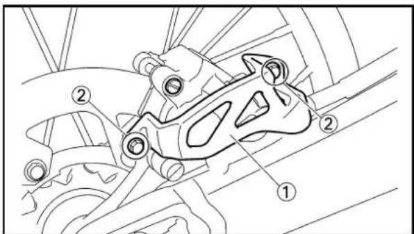
4. Install:
[Front] •Diaphragm •Master cylinder cap ① •Screw (master cylinder cap) ② 2 Nm (0.2 m•kg, 1.4 ft•lb)
[Rear]
- Diaphragm - Master cylinder cap ① - Bolt (master cylinder cap) ②
2 Nm (0.2 m•kg, 1.4 ft•lb)
CAUTION:
After installation, while pulling the lever in or pushing down on the pedal, check whether there is any brake fluid leaking where the union bolts are installed respectively at the master cylinder and caliper.
A Front B Rear
- Install: (rear brake only)
- Protector ① - Bolt (protector) ②
7 Nm (0.7 m•kg, 5.1 ft•lb)
FREIN AVANT ET FREIN ARRIERE VORDERRADBREMSE UND HINTERRADBREMSE FRENO ANTERIORE E FRENO POSTERIORE
2. Purger de l'air:
Extent of removal: ①Front fork removal
| Extent of removal Order Part name Q'ty Remarks | ||||
| Preparation for removal | FRONT FORK REMOVALHold the machine by placing the suitable stand under the engine.Front wheel Refer to “FRONT WHEEL AND Front caliper Refer to “FRONT BRAKE AND Number plate | △WARNINGSupport the machine securely so there is no danger of it falling over. REAR WHEEL”section.REAR BRAKE”section. | ||
| 1 Protector 12 Brake hose holder 23 Pinch bolt (handle crown) 2 Only loosening.4 Cap bolt 15 Pinch bolt (under bracket) 2 Only loosening.6 Front fork 1 | Loosen when disassembling the front fork. | |||
FOURCHE AVANT
② Damper rod removal
| Extent of removal Order Part name Q'ty Remarks | |||
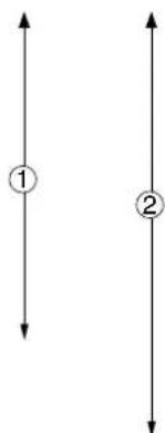 | FRONT FORK DISASSEMBLY1Cap bolt 1 Refer to “REMOVAL POINTS”.2Fork spring 1 Drain the folk oil.3Dust seal 14Stopper ring 1 Refer to “REMOVAL POINTS”5Inner tube 16Outer tube 17Piston metal 18Slide metal 19Plain washer 110Oil seal 111Spring guide12Base valve13Damper rod | 1Use special tool.1Refer to “REMOVAL POINTS”. | |
DEMONTAGE DE LA FOURCHE AVANT
Etendue de dépose:
The front fork requires careful attention. So it is recommended that the front fork be maintained at the dealers.
CAUTION:
To prevent an accidental explosion of air, the following instructions should be observed:
- The front fork with a built-in piston rod has a very sophisticated internal construction and is particularly sensitive to foreign material.
Use enough care not to allow any foreign material to come in when the oil is replaced or when the front fork is disassembled and reassembled.
- Before removing the cap bolts or front forks, be sure to extract the air from the air chamber completely.

natural_image
Line drawing of a hand holding a cylindrical object with a numbered label (1) on the shaft, no text or symbols present.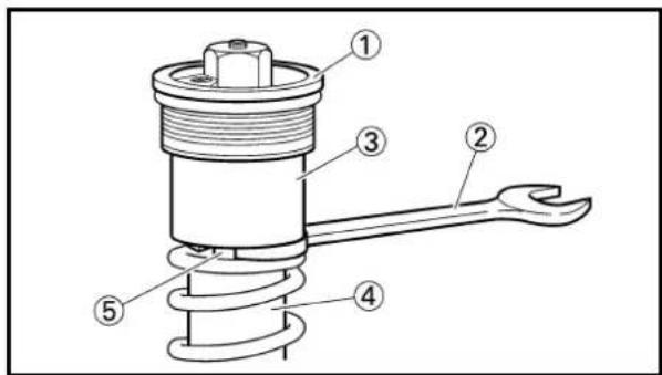
EC553000
REMOVAL POINTS
EC553151
Cap bolt
- Remove:
- Cap bolt ①
From the outer tube.
NOTE:
Before removing the front fork from the machine, loosen the cap bolt.
- Remove:
- Cap bolt ①
NOTE:
- While compressing the fork spring, set the thin type spanners ② between the spacer ③ and spring guide ④.
- Hold the locknut ⑤ and remove the cap bolt.
REMARQUES
CONCERNANT LA
MANIPULATION
N.B.:


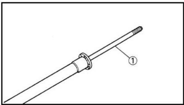
natural_image
Technical line drawing of a mechanical component with a threaded end and labeled part (1), no text or symbols present.EC553201
Inner tube
- Remove:
•Dust seal ①
-Stopper ring ②
Using slotted-head screwdriver.
CAUTION:
Take care not to scratch the inner tube.
- Remove:
- Inner tube ①
Oil seal removal steps:
- Push in slowly ①the inner tube just before it bottoms out and then pull it back quickly ⑥.
- Repeat this step until the inner tube can be pulled out from the outer tube.
EC553311
Damper rod
-
Remove:
-
Base valve ①
- Damper rod ②
NOTE:
Use a damper rod holder ③ to lock the damper rod.

Damper rod holder: YM-1423/90890-01423
EC554000
INSPECTION
EC554100
Damper rod
- Inspect:
- Damper rod ①
Bend/Damage→Replace damper rod.
CAUTION:
The front fork with a built-in piston rod has a very sophisticated internal construction and is particularly sensitive to foreign material.
Use enough care not to allow any foreign material to come in when the oil is replaced or when the front fork is disassembled and reassembled.
Tube interne
- Déposer:
•Joint antipoussière ①
•Bague d'arrêt ②

natural_image
Diagram of a coiled spring with labeled dimension 'a' (no text or symbols beyond label)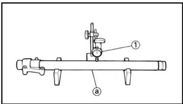

natural_image
Line drawing of a cylindrical pipe fitting with a labeled end (no text or symbols present)EC554200
Base valve
- Inspect:
- Valve assembly ① Wear/Damage→Replace.
- O-ring ② Damage→Replace.
EC554400
Fork spring
- Measure:
- Fork spring free length ⓐ Out of specification →Replace.
| Fork spring free length: | |
| Standard <Limit> | |
| 460 mm 455 mm (18.1 in) (17.9 in) |
EC554502
Inner tube
- Inspect:
- Inner tube surface (a) Score marks→Repair or replace. Use #1,000 grit wet sandpaper. Damaged oil lock piece→Replace.
- Inner tube bends Out of specification→Replace. Use the dial gauge ①.

NOTE:
The bending value is shown by one half of the dial gauge reading.
WARNING
Do not attempt to straighten a bent inner tube as this may dangerously weaken the tube.
EC554600
Outer tube
- Inspect:
-Outer tube ① Score marks/Wear/Damage→Replace.
Soupare de base
1. Examiner:
- Ensemble clapet ①
Usure/endommagement
→Changer.
• Joint torque ② Endommagement →Changer.
• Joint torque ② Endommagement →Changer.
Ressort de fourche
1. Mesurer:
EC554700
Cap bolt
-
Inspect:
-
Cap bolt ①
•O-ring ②
•Air bleed screw ③
Wear/Damage→Replace.
EC555000
ASSEMBLY AND INSTALLATION
EC5551A1
Front fork assembly
- Wash the all parts in a clean solvent.

- Install:
- Damper rod ①
To inner tube ②.
CAUTION:
To install the damper rod into the inner tube, hold the inner tube aslant. If the inner tube is held vertically, the damper rod may fall into it, damaging the valve inside.

- Install:

•Copper washer ①
•O-ring ②
- Base valve ③
To inner tube ④.

- Tighten:
- Base valve ①


55 Nm (5.5 m•kg, 40 ft•lb)
NOTE:
- Use a damper rod holder ② to lock the damper rod ③.
- Apply the LOCTITE® on the base valve thread.

Damper rod holder:
YM-1423/90890-01423
IC554700
Boulon capuchon
- Examiner:
•Boulon capuchon ①
•Joint torique ②
- Vis de purge d'air ③
Usure/endommagement
→Changer.
Hutschraube
- Prüfen:
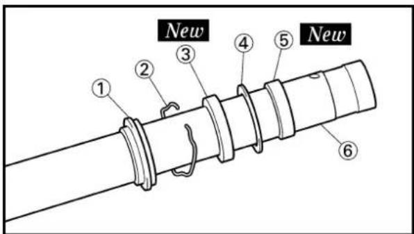


5. Install:
- Spring guide ①
- Locknut ②
To damper rod ③.
NOTE:
- Install the spring guide with its cut @facing upward.
- With its thread ⑥facing upward, fully finger tighten the locknut onto the damper rod.
6. Install:
•Dust seal ①
-Stopper ring ②
- Oil seal ③ New
- Plain washer ④
- Slide metal ⑤ New
To inner tube ⑥.
NOTE:
- Apply the fork oil on the inner tube.
- When installing the oil seal, use vinyl seat (a) with fork oil applied to protect the oil seal lip.
• Install the oil seal with its manufacture's marks or number facing the axle holder side.
7. Install:
•Piston metal ①
New
NOTE:
Install the piston metal onto the slot on inner tube.
8. Install:
-Outer tube ①
To inner tube ②.
5. Monter:
•Guide de ressort ①
- Contre-ecrou ②

natural_image
Illustration of a hand operating a mechanical press or drill bit with a numbered label (3), no text or symbols present.
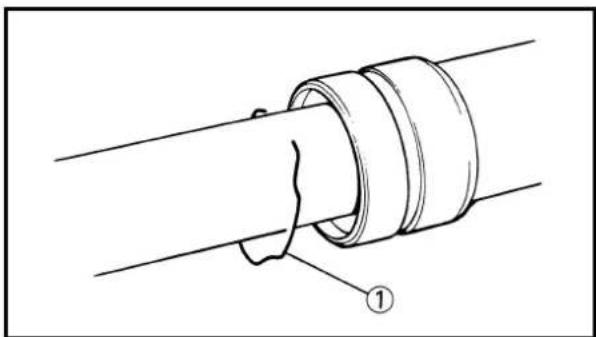
natural_image
Technical line drawing of a pipe joint with a coiled tube and labeled component (no text or symbols)
-
Install:
-
Slide metal ①
- Plain washer ②
To outer tube slot.
NOTE:
Press the slide metal into the outer tube with fork seal driver ③.

Fork seal driver: YM-01442/90890-01442
- Install:
- Oil seal ①
NOTE:
Press the oil seal into the outer tube with fork seal driver ②.

Fork seal driver: YM-01442/90890-01442
- Install:
-Stopper ring ①
NOTE:
Fit the stopper ring correctly in the groove in the outer tube.
- Install:
- Dust seal ①
NOTE:
Apply the lithium soap base grease on the inner tube.
9. Monter:
•Bague antifriction ①
•Rondelle ordinaire ②
natural_image
Illustration of a hand holding a mechanical component with directional arrows indicating movement (no text or symbols)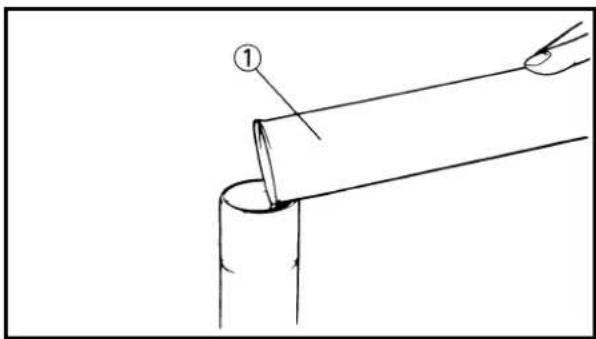
- Check:
- Inner tube smooth movement Tightness/Binding/Rough spots → Repeat the steps 2 to 12.
-
Compress the front fork fully.
-
Fill:
- Front fork oil Until outer tube top surface with recommended fork oil ①.

Recommended oil: Suspension oil "01"
CAUTION:
- Be sure to use recommended fork oil. If other oils are used, they may have an excessively adverse effect on the front fork performance.
- Never allow foreign materials to enter the front fork.

natural_image
Diagram of a hand holding a cylindrical mechanical component with a downward arrow indicating motion (no text or symbols)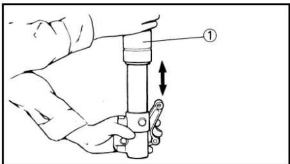
-
After filling, pump the damper rod ①slowly up and down more than 10 times to distribute the fork oil.
-
Fill:
- Front fork oil Until outer tube top surface with recommended fork oil once more.
- After filling, pump the outer tube ①slowly up and down (about 200 mm (7.9 in) stroke) to distribute the fork oil once more.
NOTE:
Be careful not to excessive full stroke. A stroke of 200 mm (7.9 in) or more will cause air to enter. In this case, repeat the steps 15 to 18.
13. Contrôler:
- Wait ten minutes until the air bubbles have been removed from the front fork, and the oil has dispense evenly in system before setting recommended oil level.
NOTE:
Fill with the fork oil up to the top end of the outer tube, or the fork oil will not spread over to every part of the front forks, thus making it impossible to obtain the correct level.
Be sure to fill with the fork oil up to the top of the outer tube and bleed the front forks.
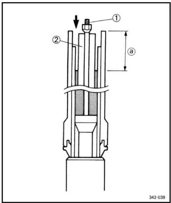

natural_image
Line drawing of hands holding a flexible tube with a pipe extending upward (no text or symbols)- Measure:
- Oil level (left and right) ⓐ Out of specification → Adjust.

Standard oil level: 135 mm (5.31 in) Extent of adjustment: 80\~150 mm (3.15\~5.91 in) From top of outer tube with inner tube and damper rod ①① fully compressed without spring.
NOTE:
Be sure to install the spring guide ②when checking the oil level.
WARNING
Never fail to make the oil level adjustment between the maximum and minimum level and always adjust each front fork to the same setting. Uneven adjustment can cause poor handling and loss of stability.

natural_image
Technical line drawing of a mechanical pulley or screw component with a central hub and threaded shaft (no text or symbols)
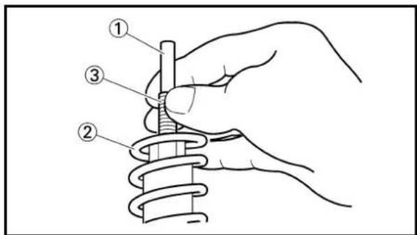

natural_image
Technical line drawing of a mechanical component with threaded spring and cap (no text or symbols)21. Measure:
- Distance ⓐ
Out of specification→Turn into the locknut.

Distance ⓐ:
20 mm (0.79 in) or more
Between damper rod ① top and
locknut ② top.
22. Loosen:
•Rebound damping adjuster ①
NOTE:
- Loosen the rebound damping adjuster finger tight.
- Record the set position of the adjuster (the amount of turning out the fully turned in position).
23. Install:
•Cushion rubber ①
- Washer ②
- Spacer ③
To cap bolt ④.
NOTE:
Install the cushion rubber with its smaller dia.end @facing the cap bolt.
24. Install:
- Push rod ①
•Fork spring ②
NOTE:
• Install the fork spring with the damper rod ③ pulled up.
• Install the fork spring with its smaller pitch end facing the cap bolt. (For EUROPE)
- After installing the fork spring, hold the damper rod end so that it will not go down.
25. Install:
- Cap bolt ①
Fully tighten the cap bolt onto the damper rod by hand.
21. Mesurer:
•Distance a

natural_image
Line drawing of a hand holding a cylindrical object with a numbered label (1), no text or symbols present.


- Tighten:
- Cap bolt (locknut) ①
29 Nm (2.9 m•kg, 21 ft•lb)
NOTE:
- While compressing the fork spring, set the thin type spanners ② between the spacer ③ and spring guide ④.
- Hold the locknut ⑤ and tighten the cap bolt with specified torque.
- Install:
- Cap bolt ①
To outer tube.
NOTE:
Temporarily tighten the cap bolt.
- Install:
- Protector guide ①
EC5552A1
Installation
- Install:
- Front fork ①
NOTE:
- Temporarily tighten the pinch bolts (under bracket).
-
Do not tighten the pinch bolts (handle crown) yet.
-
Tighten:
- Cap bolt ①
30 Nm (3.0 m•kg, 22 ft•lb)
- Adjust:
- Front fork top end ⓐ

Front fork top end (standard) @5 mm (0.20 in)
26. Serrer:
•Boulon capuchon ①

29 Nm (2,9 m•kg, 21 ft•lb)
N.B.:
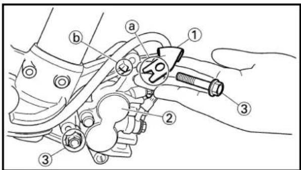

4. Tighten:
•Pinch bolt (handle crown) ①
23 Nm (2.3 m•kg, 17 ft•lb)
-Pinch bolt (under bracket) ②
20 Nm (2.0 m•kg, 14 ft•lb)
CAUTION:
Tighten the under bracket to specified torque. If torqued too much, it may cause the front fork to malfunction.
5. Install:
- Brake hose holder ①
- Caliper ②
•Bolt (caliper) ③
23 Nm (2.3 m•kg, 17 ft•lb)
NOTE:
Fit the brake hose holder cut Ⓐover the projection ⓑon the front fork and clamp the brake hose.
6. Install:
- Brake hose holder ①
•Bolt (brake hose holder) ②
10 Nm (1.0 m•kg, 7.2 ft•lb)
•Protector ③
- Bolt (protector) ④
10 Nm (1.0 m•kg, 7.2 ft•lb)
NOTE:
When installing the brake hose holder, align the top ① of the brake hose neck with the brake hose holder bottom ②. Then pass the brake hose ⑤ in front of the axle boss ⑥ and fit it into the hose groove ⑦ so that the brake hose does not contact the nut (wheel axle).
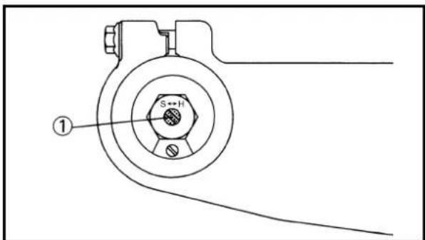
7. Adjust:
- Rebound damping force
NOTE:
Turn in the damping adjuster ①finger-tight and then turn out to the originally set position.
4. Serrer:
Extent of removal: ① Handlebar removal
| Extent of removal Order Part name Q'ty Remarks | ||||
| Preparation for HANDLE removal | REMOVALNumber plate Remove the clamp portion only. | |||
| 1 | 1 Clutch cable 1 Disconnect at the lever side.2 Clutch lever holder 13 “ENGINE STOP” button 14 Master cylinder 1 Refer to “REMOVAL POINTS”.5 Throttle cable cap 1 Turn over the cap cover.6 Throttle cable 1 Disconnect at the throttle side.7 Throttle 1 Loosen the bolts.8 Cap cover 19 Collar 110 Grip (left)11 Handlebar holder (upper)12 Handlebar | |||
| 1 Refer to “REMOVAL POINTS”.21 | ||||
GUIDON
Extent of removal: ①Throttle disassembly
| Extent of removal Order Part name Q'ty Remarks | |||
| THROTTLE DISASSEMBLY1Grip cap (lower) 12Grip cap (upper) 13Grip assembly 14Grip (right) 1 Refer to “REMOVAL POINTS”.5Tube guide 1 | |||
DEMONTAGE DE L'ACCELERATEUR
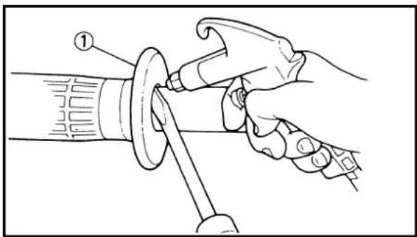

natural_image
Simple line drawing of a bent tool or tool with a labeled component (no text or symbols present)

EC5B3000
REMOVAL POINTS
EC5B3100
Master cylinder
- Remove:
• Master cylinder bracket ①
- Master cylinder ②
CAUTION:
- Do not let the master cylinder hang on the brake hose.
- Keep the master cylinder cap side horizontal to prevent air from coming in.
EC5B3200
Grip
- Remove:
•Grip ①
NOTE:
Blow in air between the handlebar or tube guide and the grip. Then remove the grip which has become loose.
EC5B4000
INSPECTION
EC5B4100
Handlebar
- Inspect:
- Handlebar ①
Bends/Cracks /Damage→Replace.
WARNING
Do not attempt to straighten a bent handlebar as this may dangerously weaken the handlebar.
EC5B5000
ASSEMBLY AND INSTALLATION
EC5B5100
Throttle assembly
- Install
•Grip (right) ①
Apply the adhesive on the tube guide ②.
NOTE:
- Before applying the adhesive, wipe off grease or oil on the tube guide surface ⓐ with a lacquer thinner.
- Align the mating mark ⓑ on the grip (right) with the slot Ⓒ in the tube guide.
POINTS DE DEPOSE
Maître-cylindre
- Déposer:
Curvature/Incrinature/Danni
→Sostituirlo.
AVVERTENZA
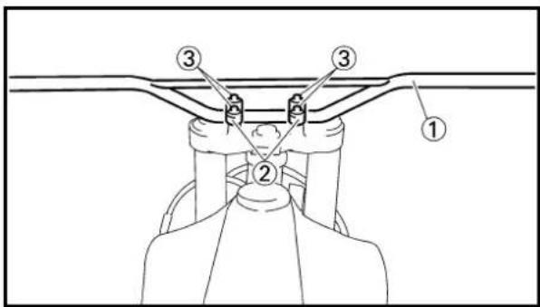


2. Install:
•Grip cap (upper) ①
•Grip cap (lower) ②
- Bolt (grip cap) ③
NOTE:
Temporarily tighten the bolts (grip cap).
EC5B5210
Handlebar
1. Install:
- Handlebar ①
- Handlebar holder ②
• Bolt (handlebar holder) ③
28 Nm (2.8 m•kg, 20 ft•lb)
NOTE:
- The upper handlebar holder should be installed with the punched mark @forward.
- First tighten the bolts on the front side of the handlebar holder, and then tighten the bolts on the rear side.
2. Install:
•Grip (left) ① Apply the adhesive to the handlebar ②.
NOTE:
- Before applying the adhesive, wipe off grease or oil on the handlebar surface @with a lacquer thinner.
• Install the grip (left) to the handlebar so that the line ⑥ between the two arrow marks faces straight upward.
3. Install:
- Collar ①
- Cap cover ②
- Throttle ③
NOTE:
- Apply the lithium soap base grease on the throttle grip sliding surface.
- Tighten the grip cap bolts temporarily without the throttle being fixed to the handlebar.
2. Monter:


natural_image
Technical line drawing of a mechanical connector or fitting with labeled part (1), no text or symbols present
4. Install:
- Throttle cable ①
To tube guide ②.
NOTE:
Apply the lithium soap base grease on the throttle cable end and tube guide cable winding portion.
5. Install:
- Roller ①
• Collar ②
NOTE:
- Apply the lithium soap base grease on the roller sliding surface.
- Install the roller so that the "UPPER" mark ⓐ faces upward.
•Pass the throttle cable in the groove ⑥in the roller
6. Install:
- Throttle cable cap ①
- Screw (throttle cable cap) ②
1 Nm (0.1 m•kg, 0.7 ft•lb)
7. Adjust:
- Throttle grip free play
Refer to "THROTTLE CABLE ADJUSTMENT" section in the CHAPTER 3.
8. Install:
- Cap cover ①
9. Install:
- Master cylinder ①
• Master cylinder bracket ②
• Bolt (master cylinder bracket) ③
9 Nm (0.9 m•kg, 6.5 ft•lb)
NOTE:
•Install the bracket so that the arrow mark ⓐ faces upward.
- First tighten the bolt on the upper side of the master cylinder bracket, and then tighten the bolt on the lower side.
4. Monter:
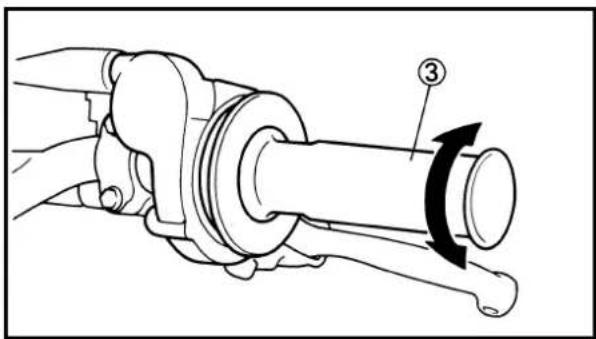
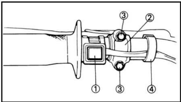


10. Install:
- Bolt (grip cap) ①
4 Nm (0.4 m•kg, 2.9 ft•lb)
WARNING
• Install the grip cap so that the gaps ① and ② between the bolt (grip cap) and brake lever ② are equal. If you make a mistake in the grip cap installation position, the brake lever may contact the grip cap, resulting in poor brake performance.
• After tightening the bolts, check that the throttle grip ③ moves smoothly. If it does not, retighten the bolts for adjustment.
11. Install:
- "ENGINE STOP" button ①
- Clutch lever holder ②
- Bolt (clutch lever holder) ③
4 Nm (0.4 m•kg, 2.9 ft•lb)
- Clamp ④
NOTE:
- The "ENGINE STOP" button, clutch lever holder and clamp should be installed according to the dimensions shown.
- Pass the "ENGINE STOP" button lead in the middle of the clutch holder.
12. Install:
- Clutch cable ①
NOTE:
Apply the lithium soap base grease on the clutch cable end.
13. Adjust:
- Clutch lever free play Refer to "CLUTCH ADJUSTMENT" section in the CHAPTER 3.
- Monter:
- Clamp the clamp portion @of the number plate to the handlebar.
-
Insert the end of the fuel breather hose ① into the hole of the number plate.
-
Fixer la partie de fixation ⓐde la plaque d'immatriculation au guidon.
-
Introduire l'extrémité du conduit d'aération de carburant ①dans les trous de la plaque d'immatriculation.
-
Das Klemmteil ④des Nummernschildes an der Lenkstange festklemmen.
-
Das Ende des Kraftstoffbelüftungsschlauches ①in die Bohrung des Nummernschildes einführen.
-
Bloccare la parte della brida Ⓐ della targa sul manubrio.
- Inserire l'estremità dello sfiato del carburante ①nel foro della targa.
EC560000
STEERING

Extent of removal: ① Under bracket removal ② Bearing removal
| Extent of removal Order Part name Q'ty Remarks | ||||
| Preparation for removal | STEERING REMOVALHold the machine by placing the suitable stand under the engine.Number plateHandlebar Refer to “HANDLEBAR” section.Cable guideFront fender | |||
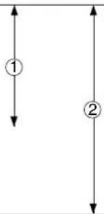 | 1 Steering shaft nut 12 Front fork 2 Refer to “FRONT FORK” section.3 Handle crown 14 Ring nut 1 Use special tool.5 Under bracket 16 Ball race cover 17 Bearing (upper) 18 Bearing (lower) 1 Refer to “REMOVAL POINTS”.9 Ball race 2 Refer to “REMOVAL POINTS”. | Refer to “REMOVAL POINTS”. | ||
DIRECTION
ETAPES DE SERRAGE:
EC563000
REMOVAL POINTS
EC563202
Ring nut
- Remove:
- Ring nut ①
Use the ring nut wrench ②.

Ring nut wrench: YU-33975/90890-01403
WARNING
Support the steering shaft so that it may not fall down.
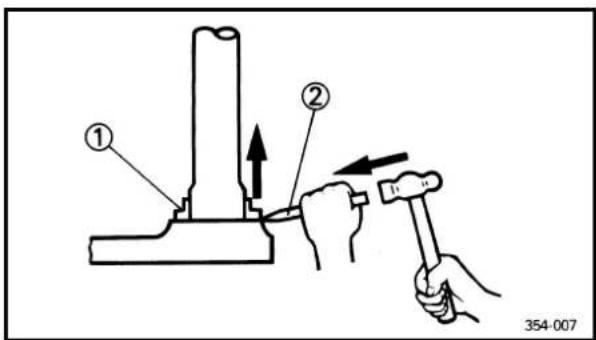
EC563300
Bearing (lower)
- Remove:
- Bearing (lower) ①
Use the floor chisel ②.
CAUTION:
Take care not to damage the steering shaft thread.

EC563400
Ball race
- Remove:
- Ball race ①
Remove the ball race using long rod ② and the hammer.

EC564000
INSPECTION
EC564200
Steering shaft
- Inspect:
- Steering shaft ①
Bend/Damage →Replace.
POINTS DE DEPOSE
Ecrou annulaire
- Déposer:
•Ecrou annulaire ①
natural_image
Hand holding a mechanical component with a rotating arrow indicating rotation (no text or symbols)EC564101
Bearing and ball race
- Wash the bearings and ball races with a solvent.
- Inspect:
•Bearing ①
- Ball race
Pitting/Damage →Replace bearings and ball races as a set.
Install the bearing in the ball races. Spin the bearings by hand. If the bearings hang up or are not smooth in their operation in the ball races, replace bearings and ball races as a set.

EC565000
ASSEMBLY AND INSTALLATION
EC565113
Under bracket
- Install:
•Bearing (lower) ①
NOTE:
Apply the lithium soap base grease on the dust seal lip and bearing inner circumference.

-
Install:
-
Ball race
•Bearing (upper) ① - Ball race cover ②
NOTE:
Apply the lithium soap base grease on the bearing and ball race cover lip.

- Install:
•Under bracket ①
NOTE:
Apply the lithium soap base grease on the bearing and the portion @of the steering shaft.
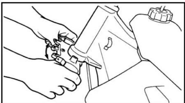
natural_image
Line drawing of hands using a tool to adjust or install a mechanical component (no text or symbols present)
natural_image
Hand holding a threaded mechanical component, no text or symbols visible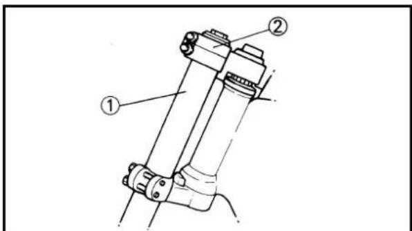
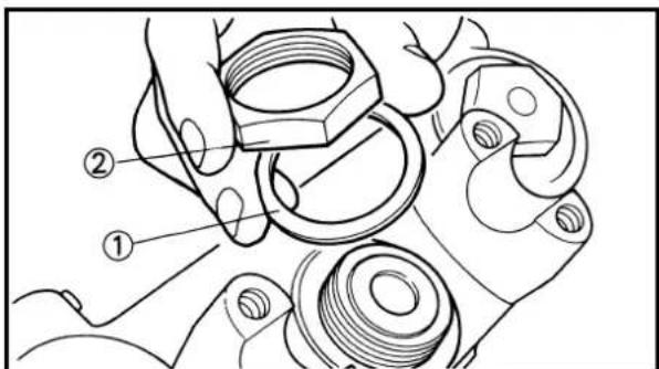
4. Install:
- Plain washer ①
•Ring nut ②
7 Nm (0.7 m•kg, 5.1 ft•lb)
Tighten the ring nut using the ring nut wrench ③.
Refer to "STEERING HEAD INSPECTION AND ADJUSTMENT" section in the CHAPTER 3.
- Check the steering shaft by turning it lock to lock. If there is any binding, remove the steering shaft assembly and inspect the steering bearings.
6. Install:
- Plain washer ①
7. Install:
- Front fork ①
- Handle crown ②
NOTE:
- Temporarily tighten the pinch bolts (under bracket).
- Do not tighten the pinch bolts (handle crown) yet.
8. Install:
- Plain washer ①
•Steering shaft nut ②
145 Nm (14.5 m·kg, 105 ft·lb)
4. Monter:
•Rondelle ordinaire ①
•Ecrou annulaire ②
7 Nm (0,7 m•kg, 5,1 ft•lb)
natural_image
Technical line drawing of mechanical components with no visible text or symbols
-
After tightening the nut, check the steering for smooth movement. If not, adjust the steering by loosening the ring nut little by little.
-
Adjust:
- Front fork top end ⓐ

Front fork top end (standard) a:5 mm (0.20 in)
- Tighten:
•Pinch bolt (handle crown) ①
23 Nm (2.3 m•kg, 17 ft•lb)
•Pinch bolt (under bracket) ②
20 Nm (2.0 m•kg, 14 ft•lb)
CAUTION:
Tighten the under bracket to specified torque. If torqued too much, it may cause the front fork to malfunction.
Extent of removal: ①Swingarm removal
| Extent of removal Order Part name Q'ty Remarks | |||
| Preparation for removal | SWINGARM REMOVALHold the machine by placing the suitable stand under the engine.Brake hose holder Refer to “FRONT BRAKE AND Rear caliperBolt (brake pedal) Shift the brake pedal backward.Drive chain | ||
| 1 Chain support 12 Chain tensioner (lower) 13 Bolt (rear shock absorber-relay arm)4 Bolt (connecting rod) 15 Pivot shaft 16 Swingarm 1 | 1 Hold the swingarm. | ||
BRAS OSCILLANT
① Swingarm disassembly ② Connecting rod removal and disassembly
③ Relay arm removal and disassembly
| Extent of removal Order Part name Q'ty Remarks | |||
 | SWINGARM DISASSEMBLY | ||
| 1Cap 22Relay arm 13Connecting rod 14Collar 25Oil seal 26Thrust bearing 27Bush 28Oil seal 89Bearing 8 Refer to “REMOVAL POINTS”. | |||
DEMONTAGE DU BRAS OSCILLANT
Etendue de dépose:


EC573000
REMOVAL POINTS
EC573201
Bearing
- Remove:
•Bearing ①
NOTE:
Remove the bearing by pressing its outer race.
EC574010
INSPECTION
Wash the bearings, bushes, collars, and covers in a solvent.
EC574111
Swingarm
- Inspect:
•Bearing ①
•Bush ②
Free play exists/Unsmooth revolution/Rust →
Replace bearing and bush as a set.
- Inspect:
- Oil seal ③
Damage →Replace.
EC574211
Relay arm
- Inspect:
•Bearing (polylube bearing) ①
•Collar ②
Free play exists/Unsmooth revolution/Rust →
Replace bearing and collar as a set.
- Inspect:
•Bearing (polylube bearing) ①
Loss of solid lubrication →Replace.
- Oil seal ③
Damage >Replace.
NOTE:
Polylube bearings, with solid lubrication, have been adopted with the intent to make the needle bearings, used in this model, maintenance free. With polylube bearings, no grease nipple and regular lubrication is necessary. However, grease should be applied to all oil seals and collars when removed or installed.
POINTS DE DEPOSE
Roulement
- Déposer:
- Roulement ①
N.B.:
EC574311
Connecting rod
- Inspect:
•Bearing (polylube bearing) ①
•Collar ②
Free play exists/Unsmooth revolution/Rust → Replace bearing and collar as a set.
- Inspect:
•Bearing (polylube bearing) ①
Loss of solid lubrication →Replace.
- Oil seal ③
Damage →Replace.
NOTE:
Polylube bearings, with solid lubrication, have been adopted with the intent to make the needle bearings, used in this model, maintenance free. With polylube bearings, no grease nipple and regular lubrication is necessary. However, grease should be applied to all oil seals and collars when removed or installed.

EC575000
ASSEMBLY AND INSTALLATION
EC575202
Bearing and oil seal
- Install:
•Bearing ①
- Oil seal ②
To swingarm.
NOTE:
- Apply the molybdenum disulfide grease on the bearing when installing.
• Install the bearing by pressing it on the side having the manufacture's marks or numbers. - First install the outer and then the inner bearings to a specified depth from inside.

Installed depth of bearings:
Outer a: Zero mm (Zero in)
Inner b:8.5 mm (0.33 in)
Bielle
-
Examiner:
-
Roulement (roulement Polylube) ①
•Collerette ②
- Install:
•Bearing ①
•Oil seal ②
To relay arm.
NOTE:
- Apply the molybdenum disulfide grease on the bearing when installing.
• Install the bearing by pressing it on the side having the manufacture's marks or numbers.

Installed depth of bearings ① 5 mm (0.20 in)
- Install:
•Bearing ①
- Oil seal ②
To connecting rod.
NOTE:
- Apply the molybdenum disulfide grease on the bearing when installing.
• Install the bearing by pressing it on the side having the manufacture's marks or numbers.

Installed depth of bearings ①② 5 mm (0.20 in)
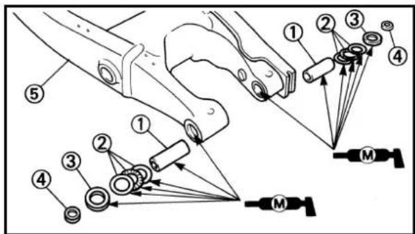

EC5751B3
Swingarm
- Install:
•Bush ①
•Thrust bearing ②
- Oil seal ③
•Collar ④
To swingarm ⑤.
NOTE:
Apply the molybdenum disulfide grease on the bushes, thrust bearings and oil seal lips.
- Install:
•Collar ①
To relay arm ②.
NOTE:
Apply the molybdenum disulfide grease on the collars and oil seal lips.
2. Monter:

3. Install:
•Collar ①
To connecting rod ②.
NOTE:
Apply the molybdenum disulfide grease on the collar and oil seal lips.
4. Install:
- Connecting rod ①
- Bolt (connecting rod) ②
- Plain washer ③
•Nut (connecting rod) ④
80 Nm (8.0 m•kg, 58 ft•lb)
To relay arm ⑤.
NOTE:
Apply the molybdenum disulfide grease on the bolt.


5. Install:
- Relay arm ①
- Bolt (relay arm) ②
- Plain washer ③
- Nut (relay arm) ④
To swingarm.
NOTE:
- Apply the molybdenum disulfide grease on the bolt.
- Do not tighten the nut yet.
6. Install:
- Swingarm ①
- Pivot shaft ②
85 Nm (8.5 m•kg, 61 ft•lb)
NOTE:
- Apply the molybdenum disulfide grease on the pivot shaft.
- Insert the pivot shaft from right side.
3. Monter:
•Collerette ①
Au bielle ②.
N.B.:


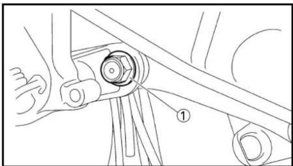
natural_image
Technical line drawing of a mechanical assembly with no visible text or symbols
natural_image
Technical line drawing of a mechanical assembly with no visible text or symbols7. Check:
- Swingarm side play ⓐ Free play exists → Replace thrust bearing.
- Swingarm up and down movement ⑥ Unsmooth movement/Binding/Rough spots→Grease or replace bearings, bushes and collars.
8. Install:
•Bolt (connecting rod) ①
- Plain washer ②
•Nut (connecting rod) ③
NOTE:
- Apply the molybdenum disulfide grease on the bolt.
- Do not tighten the nut yet.
9. Install:
•Bolt (rear shock absorber-relay arm) ①
•Nut (rear shock absorber-relay arm) ②
53 Nm (5.3 m•kg, 38 ft•lb)
NOTE:
Apply the molybdenum disulfide grease on the bolt.
10. Tighten:
•Nut (connecting rod) ①
80 Nm (8.0 m•kg, 58 ft•lb)
11. Tighten:
- Nut (relay arm) ①
80 Nm (8.0 m·kg, 58 ft·lb)
7. Contrôler:
80 Nm (8,0 m•kg, 58 ft•lb)
7. Kontrollieren:
80 Nm (8,0 m•kg, 58 ft•lb)
7. Controllare:
80 Nm (8,0 m•kg, 58 ft•lb)
11. Serrer:
80 Nm (8,0 m•kg, 58 ft•lb)
11. Festziehen:
80 Nm (8,0 m•kg, 58 ft•lb)
11. Serrare:
80 Nm (8,0 m•kg, 58 ft•lb)


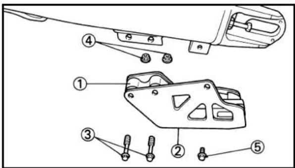
- Install:
- Cap ①
NOTE:
Install the cap (right) with its mark @facing forward.
- Install:
•Bolt [chain tensioner (lower)] ①
- Plain washer ②
•Collar ③
- Chain tensioner ④
•Nut [chain tensioner (lower)] ⑤
19 Nm (1.9 m•kg, 13 ft•lb)
-
Install:
-
Chain support ①
•Support cover ②
•Bolt {chain support [ℓ=50mm (1.97in)]} ③ - Nut (chain support) ④
7 Nm (0.7 m•kg, 5.1 ft•lb)
•Bolt { support cover [ℓ=10mm (0.39in)]} ⑤
7 Nm (0.7 m•kg, 5.1 ft•lb)
12.Monter:
- Capuchon ①
N.B.:
① Rear shock absorber removal
Rear shock absorber disassembly
| Extent of removal Order Part name Q'ty Remarks | ||||
| Preparation for removal | REAR SHOCK ABSORBER REMOVALHold the machine by placing the suitable stand under the engine.Seat Refer to “SEAT, FUEL TANK AND Silencer Refer to “EXHAUST PIPE AND | ⚠WARNINGSupport the machine securely so there is no danger of it falling over.SIDE COVERS” section.SILENCER” section. | ||
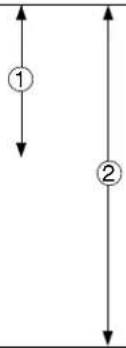 | 1 Clamp (air cleaner joint) 1 Loosen the screw(air cleaner joint).2 Rear frame 13 Bolt (rear shock absorber-relay arm)4 Bolt (rear shock absorber-frame) 15 Rear shock absorber 16 Locknut 17 Adjuster 18 Spring guide (lower) 19 Spring guide (upper) 110 Spring (rear shock absorber)11 Bearing | 1 Hold the swingarm.12 Refer to “REMOVAL POINTS”. | ||
AMORTISSEUR ARRIERE
Etendue de dépose:
This shock absorber is provided with a separate type tank filled with high-pressure nitrogen gas. To prevent the danger of explosion, read and understand the following information before handling the shock absorber.
The manufacturer can not be held responsible for property damage or personal injury that may result from improper handling.
- Never tamper or attempt to disassemble the cylinder or the tank.
- Never throw the shock absorber into an open flame or other high heat. The shock absorber may explode as a result of nitrogen gas expansion and/or damage to the hose.
- Be careful not to damage any part of the gas tank. A damaged gas tank will impair the damping performance or cause a malfunction.
- Take care not to scratch the contact surface of the piston rod with the cylinder; or oil could leak out.
- Never attempt to remove the plug at the bottom of the nitrogen gas tank. It is very dangerous to remove the plug.
- When scrapping the shock absorber, follow the instructions on disposal.

natural_image
Technical illustration of a mechanical assembly with coiled spring and housing (no text or symbols)EC587000
NOTES ON DISPOSAL (YAMAHA DEALERS ONLY)
Before disposing the shock absorber, be sure to extract the nitrogen gas from valve ①. Wear eye protection to prevent eye damage from escaping gas and/or metal chips.
WARNING
To dispose of a damaged or worn-out shock absorber, take the unit to your Yamaha dealer for this disposal procedure.
REMARQUES CONCERNANT LA MANIPULATION
⚠AVERTISSEMENT


natural_image
Technical diagram of a mechanical device with labeled component (1), showing internal components and directional arrows (no text or symbols beyond labels)
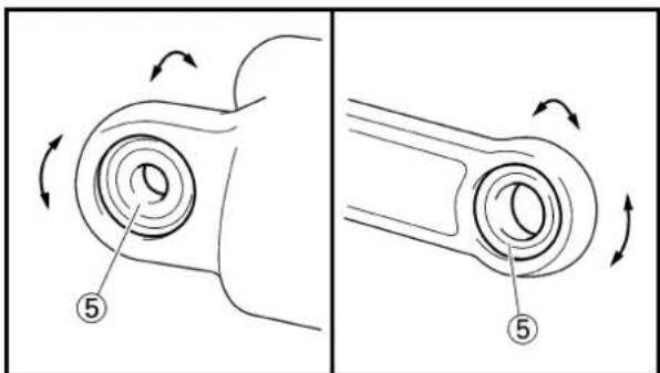
natural_image
Diagram showing two mechanical components with rotational arrows and numbered callouts (no text or symbols)EC583000
REMOVAL POINTS
EC583320
Bearing
- Remove:
•Stopper ring (upper bearing) ①
NOTE:
Press in the bearing while pressing its outer race and remove the stopper ring.
- Remove:
• Upper bearing ①
NOTE:
Remove the bearing by pressing its outer race.
- Remove:
- Lower bearing ①
NOTE:
Remove the bearing by pressing its outer race.
EC584000
INSPECTION
EC584110
Rear shock absorber
- Inspect:
- Damper rod ①
Bends/Damage →Replace absorber assembly.
- Shock absorber ②
Oil leaks →Replace absorber assembly.
Gas leaks →Replace absorber assembly.
- Spring ③
Damage →Replace spring.
Fatigue →Replace spring.
Move spring up and down.
- Spring guide ④
Wear/Damage →Replace spring guide.
•Bearing ⑤
Free play exists/Unsmooth revolution/
Rust → Replace.
POINTS DE DEPOSE
Roulement
- Déposer:

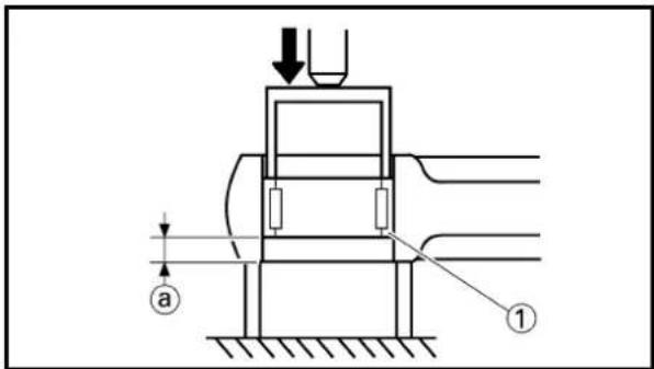
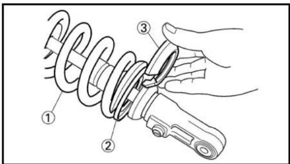

natural_image
Technical illustration of a mechanical suspension component with threaded shaft and spring (no text or symbols)EC585000
ASSEMBLY AND INSTALLATION
EC585320
Bearing
- Install:
•Upper Bearing ①
NOTE:
Install the bearing parallel until the stopper ring groove appears by pressing its outer race.
CAUTION:
Do not apply the grease on the bearing outer race because it will wear the rear shock absorber surface on which the bearing is press fitted.
- Install:
- Stopper ring (upper bearing) ①
New
NOTE:
After installing the stopper ring, push back the bearing until it contacts the stopper ring.
- Install:
- Lower bearing ①
NOTE:
Install the bearing by pressing it on the side having the manufacture's marks or numbers.

Installed depth of the bearing ⓐ 4 mm (0.16 in)
EC585111
Spring (rear shock absorber)
-
Install:
-
Spring ①
•Spring guide (upper) ② -
Spring guide (lower) ③
-
Tighten:
-Adjuster ①
REMONTAGE ET MONTAGE
Roulement
- Monter:
natural_image
Technical line drawing of a mechanical spring assembly with dimension label (a), no text or symbols present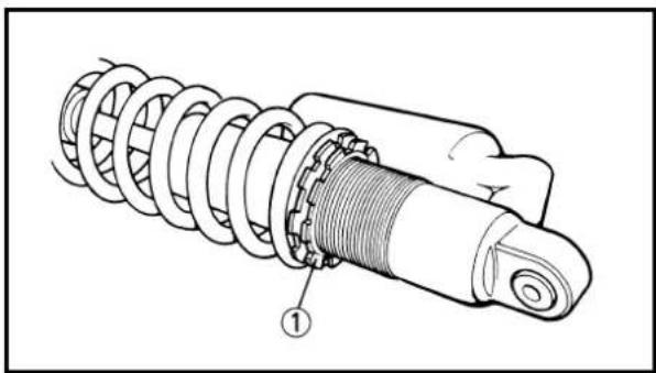
natural_image
Technical illustration of a mechanical suspension or shock absorber assembly (no text or symbols)3. Adjust:
•Spring length (installed) ⓐ
| Spring length (installed) a8 | ||
| Standard length | Extent of adjustment | |
| 251 mm (9.88 in) | 240.5~258.5 mm(9.47~10.18 in) | |
| *262 mm (10.31 in) | *255.5~273.5 mm(10.06~10.77 in) | |
*For EUROPE
NOTE:
The length of the spring (installed) changes 1.5 mm (0.06 in) per turn of the adjuster.
CAUTION:
Never attempt to turn the adjuster beyond the maximum or minimum setting.
4. Tighten:
- Locknut ①
EC5852B5
Rear shock absorber
1. Install:
•Dust seal ①
•O-ring ② New
•Collar ③
NOTE:
- Apply the molybdenum disulfide grease on the bearing.
- Apply the lithium soap base grease on the dust seals, O-rings and collars.
2. Install:
- Bush ①
•Collar ②
•Dust seal ③
NOTE:
- Apply the molybdenum disulfide grease on the bearing.
-
Apply the lithium soap base grease on the bush, collars and dust seals.
• Install the dust seals with their lips facing outward. -
Régler:

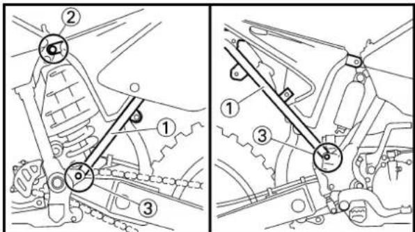

- Install:
•Rear shock absorber
- Install:
•Bolt (rear shock absorber-frame) ①
•Nut (rear shock absorber-frame) ②
56 Nm (5.6 m•kg, 40 ft•lb)
NOTE:
Apply the molybdenum disulfide grease on the bolt.
- Install:
•Bolt (rear shock absorber-relay arm) ①
•Nut (rear shock absorber-relay arm) ②
53 Nm (5.3 m•kg, 38 ft•lb)
NOTE:
Apply the molybdenum disulfide grease on the bolt.
-
Install:
-
Rear frame ①
- Bolt [rear frame (upper)] ②
32 Nm (3.2 m•kg, 23 ft•lb)
•Bolt [rear frame (lower)] ③
29 Nm (2.9 m•kg, 21 ft•lb)
- Tighten:
- Screw (air cleaner joint) ①
AMORTISSEUR ARRIERE HINTERRAD-STOSSDÄMPFER AMMORTIZZATORE POSTERIORE
- Monter:
G/L ......Green/Blue
G/W....Green/White
W/L.....White/Blue
W/R ......White/Red

EC612000
WIRING DIAGRAM

flowchart
graph TD
    A["③ Grid"]
    B["③ Module"]
    C["④ Transformer"]
    D["⑤ Power Supply"]

    E1["Terminal ①"] --> F1["B/W"]
    E1 --> F2["B/W"]
    E1 --> F3["B"]

    E2["② Power Supply"]
    E2 --> E3["B"]
    E2 --> E4["B"]

    F1 --> G1["G/L"]
    F1 --> G2["G/L"]
    F2 --> H1["W/L"]
    F2 --> H2["W/L"]
    F3 --> I1["W/L"]
    F3 --> I2["W/L"]

    style A fill:#f9f,stroke:#333
    style B fill:#f9f,stroke:#333
    style C fill:#f9f,stroke:#333
    style D fill:#f9f,stroke:#333
    style E1 fill:#ccf,stroke:#333
    style E2 fill:#ccf,stroke:#333
    style E3 fill:#ccf,stroke:#333
    style E4 fill:#ccf,stroke:#333
PARTIE ELETRIQUE COMPOSANTS ELECTRIQUES ET SCHEMA DE CABLAGE COMPOSANTS ELECTRIQUES
Use the following steps for checking the possibility of the malfunctioning engine being attributable to ignition system failure and for checking the spark plug which will not spark.

flowchart
graph TD
    A["Spark gap test"] -->|No Spark| B["Check entire ignition system for connection."]
    B -->|OK| C["Check "ENGINE STOP" button."]
    C -->|No good| D["Replace."]
    C -->|OK| E["Check ignition coil."]
    E -->|No good| F["Primary coil"]
    E -->|No good| G["Secondary coil"]
    F -->|No good| H["Replace."]
    G -->|No good| I["Replace."]
    E -->|OK| J["Check spark plug cap."]
    J -->|No good| K["Replace."]
    J -->|OK| L["Check CDI magneto."]
    L -->|No good| M["Pick-up coil"]
    L -->|No good| N["Source coil"]
    M -->|No good| O["Replace."]
    N -->|No good| P["Replace."]
    L -->|OK| Q["Replace CDI unit."]
    R["*Clean or replace spark plug."] --> S
    T["Repair or replace."] --> U
    V["Replace."] --> W
*marked: Only when the ignition checker is used.
NOTE:
- Remove the following parts before inspection.
1) Seat
2) Fuel tank - Use the following special tools in this inspection.

Dynamic spark tester:
YM-34487
Ignition checker:
90890-06754

Pocket tester:
YU-3112-C/90890-03112
SYSTEME D'ALLUMAGE ETAPES DE VERIFICATION
SISTEMA DI ACCENSIONE
IC621002
EC622001
SPARK GAP TEST
- Disconnect the spark plug cap from spark plug.
- Connect the dynamic spark tester ①(ignition checker ②) as shown.
- Spark plug cap ③
- Spark plug ④
A For USA and CDN
B Except for USA and CDN
- Kick the kick starter.
- Check the ignition spark gap.
- Start engine, and increase spark gap until misfire occurs. (for USA and CDN only)

Minimum spark gap: 6.0 mm (0.24 in)
EC624000
COUPLERS AND LEADS CONNECTION INSPECTION
- Check:
- Couplers and leads connection Rust/ Dust/ Looseness/Short-circuit → Repair or replace.

EC625002
"ENGINE STOP" BUTTON INSPECTION
- Inspect:
- "ENGINE STOP" button conduct
| Tester (+) lead→Black/White lead 1 |
| Tester (−) lead→Black lead 2 |
| B/W B | Tester selector position | |||
| 1 | 2 | |||
| PUSH IN | ○— | ○ | Ω×1 | |
| FREE | ||||
Not continuous while being pushed →Replace. Continuous while being freed →Replace.
ESSAI DE L'INTERVALLE D'ETINCELLEMENT D'ALLUMAGE
ACCOPPIATORI E CONDUTTORI
- Controllare:
EC626003
IGNITION COIL INSPECTION
- Inspect:
- Primary coil resistance Out of specification →Replace.
Tester (+) lead → Orange lead ① Tester (−) lead→Black lead ②
| Primary coil Tester selector resistance position | ||
| 0.14~0.20Ω at 20°C (68°F) | × 1 | |


natural_image
Diagram of a mechanical tool with directional arrows indicating motion or rotation (no text or symbols)- Inspect:
•Secondary coil resistance Out of specification →Replace.
Tester (+) lead→Spark plug lead ① Tester (−) lead→Orange lead ②
 | Secondary coil resistance position | Tester selector |
| 6.7~10.1kΩ at 20°C (68°F) | kΩ × 1 |
NOTE:
- Remove the spark plug cap by turning it counterclockwise and inspect.
• Install the spark plug cap by turning it clockwise until it is tight.
VERIFICATION DE LA BOBINE D'ALLUMAGE
1. Examiner:
EC62B000
SPARK PLUG CAP INSPECTION
1.Inspect:
- Spark plug cap
Loose connection → Tighten.
Deteriorated/damaged →Replace. - Spark plug cap resistance
Out of specification →Replace.
| Tester (+) lead →Spark plug lead terminal 1 |
| Tester (−) lead→Spark plug terminal 2 |
| Spark plug cap Tester selector resistance position | ||
| 4~6kΩ at 20°C (68°F) | kΩ × 1 | |

EC627011
CDI MAGNETO INSPECTION
1. Inspect:
- Pick-up coil resistance
Out of specification →Replace.
| Tester (+) lead→White/Red lead 1 |
| Tester (−) lead→White/Blue lead 2 |
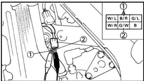
| Pick-up coil Tester selector resistance position | ||
| 248~372Ω at 20°C (68°F) | Ω × 100 | |
2. Inspect:
- Source coil 1 resistance
Out of specification →Replace.
| Tester (+) lead →Black/Red lead 1 |
| Tester (−) lead→Green/White lead 2 |
| Source coil 1 Tester selector resistance position | ||
| 720~1,080Ω at 20°C (68°F) | Ω × 100 | |
INSPECTION DU CAPUCHON DE BOUGIE
1. Examiner:
- Source coil 2 resistance Out of specification →Replace.
| Tester (+) lead >Green/Blue lead 1 Tester (−) lead→Black lead 2 |
| Source coil 2 Tester selector resistance position | ||
| 44~66Ω at 20°C (68°F) | Ω × 10 | |
EC628000
CDI UNIT INSPECTION
Check all electrical components. If no fault is found, replace the CDI unit. Then check the electrical components again.
3. Examiner:
- The role of fuel is to cool the engine, and in the case of a 2-stroke engine, to lubricate the engine in addition to power generation. Accordingly, if a mixture of air and fuel is too lean, abnormal combustion will occur, and engine seizure may result. If the mixture is too rich, spark plugs will get wet with oil, thus making it impossible to bring the engine into full play or if the worst comes to the worst, the engine may stall.
- The richness of the air-fuel mixture required for the engine will vary with atmospheric conditions of the day and therefore, the settings of the carburetor must be properly suited to the atmospheric conditions (air pressure, humidity and temperature).
- Finally, the rider himself must make a test-run and check his machine for conditions (pick-up of engine speed, road surface conditions) and for the discoloration of the spark plug(s). After taking these into consideration, he must select the best possible carburetor settings.
※ It is advisable to make a note of settings, atmospheric conditions, road surface condition, lap-time, etc. so that the memorandum can be used as a reference useful for future.
EC712000
Atmospheric conditions and carburetor setting
| Air temp. | Humidity pressure (altitude) | Air | Pressure Setting | |
| High High | Low (high) | Richer | Leaner | |
| Low Low | High (low) | Leaner | Richer |
The reason for the above tendency is that the richness or leanness of a fuel mixture depends on the density of the air (i.e. the concentration of oxygen in it).
MISE AU POINT MOTEUR
- Higher temperature expands the air with its resultant reduced density.
- Higher humidity reduces the amount of oxygen in the air by so much of the water vapor in the same air.
- Lower atmospheric pressure (at a high altitude) reduces the density of the air.

natural_image
Close-up of a spark plug with threaded end and central screw (no text or symbols visible)
natural_image
Close-up of a mechanical screw with a curved tip and central hole (no text or symbols visible)
natural_image
Close-up of a black and white spark plug with threaded end (no text or symbols visible)EC713001
Test run
After warming up the engine equipped with the standard type carburetor(s) and spark plug(s), run two or three laps of the circuit and check the smooth operation of the engine and discoloration of spark plug(s).
| Discoloration Condition of spark plug | |
| Normal | Insulator is dry and burnt brown. |
| Over burned (too lean) | Insulator is whitish. |
| Oil fouled Insulator is sooty and (too rich) wet. | |
A Normal
BOver burned (too lean)
©Oil fouled (too rich)
Ainsi:
Effect of setting parts in relation to throttle valve opening
| Setting part | Throttle valve opening | ||
| Full-closed 1/4 | 1/2 3/4 Full-open | ||
| Pilot air screw |  | ||
| Pilot jet |  | ||
 | |||
| Jet needle | Diameter of straight portion |  | |
 | |||
| Clip position |  | ||
| Throttle valve |  | ||
| Main jet |  | ||
①Throttle valve opening
②Full-open
③Full-closed

natural_image
Technical line drawing of a mechanical assembly with no visible text or symbolsEC715002
Main jet adjustment
The richness of air-fuel mixture with 1/2\~4/4 throttle can be set by changing the main jet ①.
| Standard main jet | #410 |
- Spark plug is too hot.
Select a main jet having higher calibrating No. than standard. (To be enriched)
- Spark plug is wet.
Select a main jet having lower calibrating No. than standard. (To be leaned out)
| Gicleur principal standard | #410 |
natural_image
Technical line drawing of a mechanical assembly with hoses and components (no text or symbols)EC716001
Pilot air screw adjustment
The richness of air-fuel mixture with full closed to 1/4 throttle can be set by turning the pilot air screw 1.
Turning in the pilot air screw will enrich the mixture at low speeds, and turning out it will lean out the mixture.
Standard pilot air 2 turns out screw position *1-1/2 turns out
*For EUROPE

natural_image
Technical line drawing of a mechanical component with labeled parts (no text or symbols)EC71R010
Pilot jet adjustment
The richness of air - fuel mixture with the throttle fully closed to 1/2 open can be set by turning the pilot jet 1.
It is changed when adjustment cannot be made by the pilot air screw alone.
Standard pilot jet #40
EC718010
Jet needle groove position adjustment
Should the engine be hard to run smoothly at intermediate speeds, the jet needle ①must be adjusted. If the mixture is too rich or too lean at intermediate speed operation, irregular engine operation and poor acceleration will result. Whether or not the richness of the mixture is proper is hard to be determined by means of the spark plug and therefore, it should be judged from your feeling of actual engine operation.
| Standard clip position | No.3 groove*No.4 groove |
*For EUROPE
- Too rich at intermediate speeds
Rough engine operation is felt and the engine will not pick up speed smoothly. In this case, step up the jet needle clip by one groove or 0.5 groove and move down the needle to lean out the mixture.
- Too lean at intermediate speeds
The engine breathes hard and will not pick up speed quickly. In this case, step down the jet needle clip by one groove or 0.5 groove and move up the needle to enrich the mixture.
chemical
Diagram showing DNA replication with 6CHY6-82 and 6CHY5-82 mutations, labeled with positions (a) and (b)EC719071
Jet needle adjustment
(For USA, CDN, ZA, AUS and NZ)
On the carburetors used in the YZ125, the main nozzle is a non disassembly type, so it can not be replaced. Therefore, carburetor setting requires the change of the jet needle.
- The jet needle setting parts, having the same taper angle, are available in different straight portion diameters and in different taper starting positions.
Standard jet needle 6CHY6-82

Changing from 6CHY6-82 to 6CHY5-82 has the same effect as a lowering of 0.5 clip position.
A Difference in straight portion dia.
B Difference in clip position
①Reference needle
⑥0.5 leaner
| Clip position\Diameter of straight portion | Rich Lean | |||
| ø2.810 mm (0.1106 in) | ø2.820 mm (0.1110 in) | ø2.830 mm (0.1114 in) | ||
| Rich 1 Lean 1 | richer 6CHY6-81-4 | th groove 6CHY6-82-4th groove | groove 6CHY6-83-4th groove | |
| 0.5 richer 6CH | Y5-81-4th groove 6CHY5-82 | -4th groove 6CHY5-83-4th groove | ||
| STD 6CHY6-81-3rd groove 6CHY6-82 | 3rd groove 6CHY6-83-3rd groove | |||
| 0.5 leaner 6CH | Y5-81-3rd groove 6CHY5-82 | -3rd groove 6CHY5-83-3rd groove | ||
| leaner 6CHY6-81-2nd groove 6CHY6-82-2nd groove 6CHY6-83-2nd groove | ||||

Jet needle adjustment (For EUROPE)
On the carburetors used in the YZ125, the main nozzle is a non disassembly type, so it can not be replaced. Therefore, carburetor setting requires the change of the jet needle.
- The jet needle setting parts, having the same taper angle, are available in different straight portion diameters and in different taper starting positions.
| Standard jet needle 6CHY6-82 |
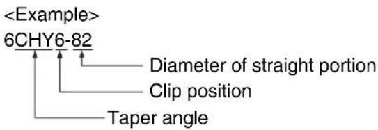
Changing from 6CHY6-82 to 6CHY5-82 has the same effect as a lowering of 0.5 clip position.
A Difference in straight portion dia.
B Difference in clip position
①Reference needle
⑥0.5 leaner
| Clip position\Diameter of straight portion | Rich Lean | |||
| ø2.810 mm (0.1106 in) | ø2.820 mm (0.1110 in) | ø2.830 mm (0.1114 in) | ||
| Rich 1 | richer 6CHY6-81-5th groove 6CHY6-82-5th groove | 6CHY6-82-5th groove 6CHY6-83-5th groove | ||
| 0.5 richer 6CHY5-81-5th groove 6CHY5-82-5th groove 6CHY5-83-5th groove | ||||
| STD 6CHY6-81-4th groove 6CHY6-82-4th groove 6CHY6-83-4th groove | ||||
| 0.5 leaner 6CHY5-81-4th groove 6CHY5-82-4th groove 6CHY5-83-4th groove | ||||
| Lean 1 | leaner 6CHY6-81-3rd groove 6CHY6-82-3rd groove 6CHY6-83-3rd groove | |||
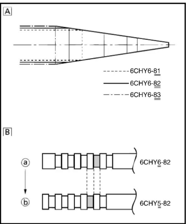
Relationship with throttle opening
The flow of the fuel through the carburetor main system is controlled by the main jet and then, it is further regulated by the area between the main nozzle and the jet needle. On the relationship between the fuel flow and the throttle opening, the fuel flow relates to the straight portion of the jet needle at full closed\~1/8 throttle, to the 1st tapered portion at 1/4 throttle, to the second tapered portion at 1/2 throttle, to the third tapered portion at 3/4 throttle and to the fourth tapered portion at full open.
Therefore, the fuel flow is balanced at each stage of throttle opening by a combination of the jet needle diameter and clip position.
6CHY6-82-3rd groove
6CHY6-82-2nd groove
6CHY6-83-3rd groove
A Lean (larger diameter)
B Rich (smaller diameter)
①Full closed
②1/4 throttle
③1/2 throttle
④3/4 throttle
⑤Full open
I 1st taper
Ⅱ 2nd taper
III 3rd taper
IV 4th taper
①Main nozzle
① Tubulure principal
EC71Q000
Carburetor setting parts
| Part name | Size | Part number | ||
| Main jet 11 | Lean | #390 137-14 | 14143-78 | |
| #400 137-14 | 14143-80 | |||
| (STD) #410 | 137-14 | 143-82 | ||
| #420 137-14 | 14143-84 | |||
| #430 137-14 | 14143-86 | |||
| #440 137-14 | 14143-88 | |||
| Rich | #450 137-14 | 143-90 | ||
| Pilot jet 22 | Lean | #30 | 4KM-14 | 142-30 |
| #32.5 | 4KM-14 | 142-32 | ||
| #35 | 4KM-14 | 142-35 | ||
| #37.5 | 4KM-14 | 142-37 | ||
| (STD) #40 | #42.5 | 4KM-14 | 142-40 | |
| #45 | 4KM-14 | 142-42 | ||
| #47.5 | 4KM-14 | 142-45 | ||
| Rich | #50 | 4KM-14 | 142-47 | |
| 4KM-14 | 142-50 | |||
| Throttle valve 33 | Rich | 3.75 | 5NY-14 | 112-37 |
| 5NY-14 | 112-40 | |||
| (STD) 4.0 | 4.25 | 5NY-14 | 112-42 | |
| Lean | ||||
| Jet needle 44 | Rich | 6CHY6-80 | 284-14 | 116-F5 |
| 6CHY6-81 | 284-14 | 116-F6 | ||
| 6CHY6-82 | 284-14 | 116-F7 | ||
| 6CHY6-83 | 284-14 | 116-F8 | ||
| 6CHY6-84 | 284-14 | 116-F9 | ||
| Lean | ||||
| Rich | 6CHY5-80 | 284-14 | 116-E5 | |
| 6CHY5-81 | 284-14 | 116-E6 | ||
| 6CHY5-82 | 284-14 | 116-E7 | ||
| 6CHY5-83 | 284-14 | 116-E8 | ||
| 6CHY5-84 | 284-14 | 116-E9 |
Road condition and examples of carburetor setting
| Parts\Conditions | General condition | Sandy condition | ||||
| Under 10°C(50°F)(Winter) | 15~25°C(59~77°F)(Spring, Autumn) | Over 30°C(86°F)(Summer) | Under 10°C(50°F)(Winter) | 15~25°C(59~77°F)(Spring, Autumn) | Over 30°C(86°F)(Summer) | |
| Main jet | #420 | #410 | #400 | #440 | #430 | #420 |
| Jet needle | 6CHY6-81-3*6CHY6-81-4 | 6CHY6-82-3*6CHY6-82-4 | 6CHY5-82-3*6CHY5-82-4 | 6CHY5-81-4*6CHY5-81-5 | 6CHY5-82-4*6CHY5-82-5 | 6CHY6-82-3*6CHY6-82-4 |
| Pilot jet | #40 | #40 | #40 | #40 | #40 | #40 |
| Pilot air screw | 1-1/2 | 2*1-1/2 | 2*1-1/2 | 1-1/2 | 2*1-1/2 | 2*1-1/2 |
*For EUROPE
EC71D040
Examples of carburetor setting depending on symptom
| Symptom Setting Checking | ||
| At full throttle Increase main jet calibration No. Discoloration of spark plug Stall at high speeds (Gradually) If tan color, it is in good condition.*Hard breathing If can not be normalized: Shearing noise Clogged float valve seat Whitish spark plug Clogged fuel hose↓Lean mixture | Clogged fuel cock | |
| At full-throttle Decrease main jet calibration No. Discoloration of spark plugStop of speed pick-up (Gradually) If tan color, it is in good condition.Slow speed pick-up *In case of racing slight enrichment If not effect: Slow response Fuel overflow from carburetorSooty spark plug↓Rich mixture | Clogged main air passage or clogged filter | |
| Lean mixture Lower jet needle clip position.(1 groove down) |  Leaner↑(Standard)↓RicherClip position indicates the position of jet needle groove, to which the clip is fitted.The position is numbered from the top.If a change in the clip position (1 groove) is effective, try another jet needle that provides a difference of 0.5 in the clip position. Leaner↑(Standard)↓RicherClip position indicates the position of jet needle groove, to which the clip is fitted.The position is numbered from the top.If a change in the clip position (1 groove) is effective, try another jet needle that provides a difference of 0.5 in the clip position. | |
| Rich mixture | Raise jet needle clip position.(1 groove up) | |
| 1/4~3/4 throttle*Hard breathingLack of speed | Lower jet needle clip position.(1 groove down) | |
| 1/4~1/2 throttleSlow speed pick-up (1 groove up)White smokePoor acceleration | Raise jet needle clip position. | |
| 0~1/4 throttle Use jet needle having a smaller Number of turns-back →*Hard breathing diameter. Correct properlySpeed down Overflow from carburetor | ||
| 0~1/4 throttle Use jet needle having a largerPoor acceleration diameter.White smoke | ||
| Unstable at low speeds Lower jet needle clip position.Pinking noise (1 groove down)Turn in pilot air screw. | ||
| Poor response at extremely Reduce pilot jet calibration No. Dragging brakelow speed Turn out pilot air screw. Overflow from carburetorIf not effect, reverse theabove procedures. | ||
| Poor response in Raise jet needle clip position.the range of low to If no effect, reverse the aboveintermediate speeds | ||
| Poor response when throttle is opened quickly | Check overall settings.Use main jet having lowercalibration No.Raise jet needle clip position.(1 groove up)If no effect, reverse the aboveprocedures. | Check air cleaner for fouling. |
| Poor engine operation | Turn in pilot air screw. | Check throttle valve operation. |
*In case of hard breathing, check the air vent hose for clogging.
※ This should be taken simply for an example. It is necessary to set the carburetor while checking the operating conditions of the engine and discoloration of spark plugs.
Normally, carburetor setting is made by means of the main jet, jet needle clip position (including one with 0.5 difference), pilot jet and pilot air screw. If the result of setting is still unsatisfactory, it is advisable to change the diameter of the straight portion the jet needle.
natural_image
Line drawing of a spark plug with threaded end and hexagonal head (no text or symbols)EC71M010
Change of the heat range of spark plugs
Judging from the discoloration of spark plugs, if they are found improper, it can be corrected by the following two methods; changing carburetor settings and changing the heat range of spark plug.
| Standard spark plug | BR9EG/NGK(resistance type) |
- In principle, it is advisable to first use spark plugs of standard heat range, and judging from the discoloration of spark plugs, adjust carburetor settings.
- If the calibration No. of the main jet must be changed by ± 30 , it is advisable to change the heat range of spark plugs and newly select the proper main jet.
NOTE:
- When checking the discoloration of spark plugs, be sure to stop the engine immediately after a run and check.
- Avoid racing.
- When changing the heat range of spark plugs, never attempt to change it more than ± 1 rank.
- When using a spark plug other than standard, check its heat range against the standard and check that it is a resistance type.
- Note that even if the discoloration seems proper, it may slightly vary with the spark plug maker and oil in use.
If you feel the engine pick up faster depending on the course condition, you can control it by changing the rotor to the one with a greater inertial mass.
| Part name Part number | *Inertial mass |
| 1 Standard rotor | 5CU-85550-11 0.0004kg·m ^2 |
| 2 Optional rotor | 5UN-85550-00 0.00045kg·m ^2 |
* Inertial mass: The inertial mass of the body is proportional to its weight and increases in proportion to the square of the distance between its rotation center and center of gravity. For the same weight, a greater distance from its rotation center produces greater inertial mass.
Greater initial mass gives a feeling of greater torque in response to engine revolutions but is accompanied by greater pick up resistance.
Engine characteristics are shown below in relation to each rotor:
- Standard rotor
Engine pickup is faster in the entire engine speed range.
Pickup is fast at an extremely low engine speed.
- Optional rotor
A feeling of torque is obtained at high engine speed.
A broader power band is felt from mid speed to over revs.
NOTE:
- Engine pick up differs according to the course condition, rider, the settings, etc. Select a suitable rotor by comparing it with the standard one in operation.
- It is difficult to be advantageous under all course conditions with a change in the rotor. Measure the lap times in accordance with race points and select a rotor to produce a good entire balance.
Sélection du rotor
Selection of the secondary reduction ratio (Sprocket)
Secondary reduction ratio = of driven sprocket teethNumber of drive sprocket teeth
| Standard secondary reduction ratio | 49/13 (3.769) |
- It is generally said that the secondary gear ratio should be reduced for a longer straight portion of a speed course and should be increased for a course with many corners. Actually, however, as the speed depends on the ground condition of the day of the race, be sure to run through the circuit to set the machine suitable for the entire course.
- In actuality, it is very difficult to achieve settings suitable for the entire course and some settings may be sacrificed. Thus, the settings should be matched to the portion of the course that has the greatest effect on the race result. In such a case, run through the entire course while making notes of lap times to find the best balance; then, determine the secondary reduction ratio.
- If a course has a long straight portion where a machine can run at maximum speed, the machine is generally set such that it can develop its maximum revolutions toward the end of the straight line, with care taken to avoid the engine over-revving.
NOTE:
Riding technique varies from rider to rider and the performance of a machine also vary from machine to machine. Therefore, do not imitate other rider's settings from the beginning but choose your own setting according to the level of your riding technique.
PARTIE CYCLE
EC72N000
Drive and driven sprockets setting parts
| Part name Size | Part number | |
| Drive sprocket 11(STD) | 12T 93 | 83A-12017 |
| 13T 9383A | -13031 | |
| 14T 93 | 83A-14054 | |
| Driven sprocket 22(STD) | 47T | 5ET-25447-00 |
| 48T | 5NY-25448-00 | |
| 49T | 5NY-25449-00 | |
| 50T | 5NY-25450-00 | |
| 51T | 5NY-25451-00 | |
| 52T | 5NY-25452-00 |
EC721003
Tire pressure
Tire pressure should be adjust to suit the road surface condition of the circuit.

Standard tire pressure: 100 kPa (1.0 kgf/cm ^2 , 15 psi)
- Under a rainy, muddy, sandy, or slippery condition, the tire pressure should be lower for a larger area of contact with the road surface.

Extent of adjustment: 60\~80 kPa (0.6\~0.8 kgf/cm², 9.0\~12 psi)
- Under a stony or hard road condition, the tire pressure should be higher to prevent a flat tire.

Extent of adjustment: 100\~120 kPa (1.0\~1.2 kgf/cm², 15\~18 psi)
The front fork setting should be made depending on the rider's feeling of an actual run and the circuit conditions.
The front fork setting includes the following three factors:
- Setting of air spring characteristics
- Change the fork oil level.
- Setting of spring preload
- Change the spring.
•Install the adjustment washer.
- Setting of damping force
- Change the compression damping.
- Change the rebound damping.
The spring acts on the load and the damping force acts on the cushion travel speed.
A
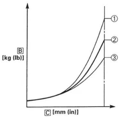
line
| Curve | Value (kg lb) | |-------|---------------| | ① | ~1.0 | | ② | ~0.8 | | ③ | ~0.6 |EC723001
Change in level and characteristics of fork oil Damping characteristic near the final stroke can be changed by changing the fork oil amount.
CAUTION:
Adjust the oil level in 5 mm (0.2 in) increments or decrements. Too low oil level causes the front fork to produce a noise at full rebound or the rider to feel some pressure on his hands or body. Alternatively, too high oil level will develop unexpectedly early oil lock with the consequent shorter front fork travel and deteriorated performance an characteristics. Therefore, adjust the front fork within the specified range.

Standard oil level:
135 mm (5.31 in)
Extent of adjustment:
80\~150 mm (3.15\~5.91 in)
From top of outer tube with inner tube and damper rod fully compressed without spring.
[A]Air spring characteristics in relation to oil level change
BLoad
©Stroke
①Max. oil level
②Standard oil level
③Min. oil level
EC727021
Spring preload adjustment
The spring preload is adjusted by installing the adjustment washer ① between the fork spring ② and damper rod ③.
CAUTION:
Do not install three or more adjustment washers for each front fork.
WARNING
Always adjust each front fork to the same setting. Uneven adjustment can cause poor handling and loss of stability.

Standard washer quantity: Zero adjustment washers Extent of adjustment: Zero \~ 2 adjustment washers
ALoad
B Fork stroke
①Without adjustment washer (standard)
⑥1 adjustment washer
©2 adjustment washers
EC72A001
Setting of spring after replacement
As the front fork setting can be easily affected by rear suspension, take care so that the machine front and rear are balanced (in position, etc.) when setting the front fork.
- Use of soft spring
Generally a soft spring gives a soft riding feeling. Rebound damping tends to become stronger and the front fork may sink deeply over a series of gaps.
To set a soft spring:
- Change the rebound damping. Turn out one or two clicks.
- Change the compression damping. Turn in one or two clicks.
2. Use of stiff spring
Generally a stiff spring gives a stiff riding feeling. Rebound damping tends to become weaker, resulting in lack of a sense of contact with the road surface or in a vibrating handlebar.
To set a stiff spring:
- Change the rebound damping.
Turn in one or two clicks.
- Change the compression damping.
Turn out one or two clicks.

flowchart
graph TD
    A["Group ①"] --> B["Group ②"]
    B --> C["Group ③"]
    style A fill:#f9f,stroke:#333
    style B fill:#bbf,stroke:#333
    style C fill:#dfd,stroke:#333
A Coverage of spring by weight
B Rider weight
①Soft
②Standard
③Stiff
2. Ressort dur
EC72P010
Front fork setting parts
- Adjustment washer ①
| TYPE (thickness) | PART NUMBER |
| T=2.3 mm (0.09 in) | 4$S-23364-L0 |
- Front fork spring ②
[Equal pitch spring]
| TYPE | SPRING RATE P | SPRING ART NUMBER | I.D. MARK (slits) |
| SOFT | 0.380 40.390 4SS0.400 4 | SS-23141-10 I-IISS-23141-20 I-IISS-23141-30 I-III | |
| STD 0 | 0.410 4XM | -23141-L0 – | |
| STIFF | 0.420 40.430 4SS0.440 4 | SS-23141-50 IISS-23141-60 IIISS-23141-70 IIIII |
[Unequal pitch spring]
| TYPE | SPRING RATE (approx.) | SPRING PART NUMBER | I.D. MARK (slits) |
| SOFT | 0.400 5ET | -23141-20 | V |
| *STD | 0.410 5 | ET-23141-L0 – | |
| STIFF | 0.420 5 | ET-23141-30 | V-II |
| 0.430 5ET | -23141-10 | V-III | |
| 0.440 5 | ET-23141-40 | V-III |
*For EUROPE
NOTE:
- The unequal pitch spring is softer in initial characteristic than the equal pitch spring and is difficult to bottom out under full compression.
•The I.D. mark (slits) ⓐ is proved on the end of the spring.
Rear suspension setting
The rear suspension setting should be made depending on the rider's feeling of an actual run and the circuit conditions.
The rear suspension setting includes the following two factors:
-
Setting of spring preload
-
Change the set length of the spring.
-
Change the spring.
-
Setting of damping force
-
Change the rebound damping.
- Change the compression damping.
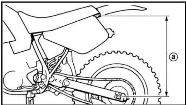
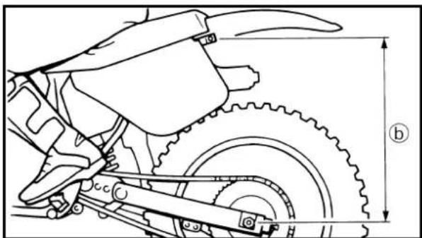
natural_image
Technical line drawing of a motorcycle's front wheel and side gear assembly (no text or symbols)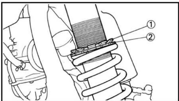
EC72C001
Choosing set length
- Place a stand or block under the engine to put the rear wheel above the floor, and measure the length @between the rear wheel axle center and the rear fender holding bolt.
- Remove the stand or block from the engine and with a rider astride the seat, measure the sunken length ⑥between the rear wheel axle center and the rear fender holding bolt.
- Loosen the locknut ① and make adjustment by turning the spring adjuster ② to achieve the standard figure from the subtraction of the length ⑥ from the length ④.

Standard figure: 90\~100 mm (3.5\~3.9 in)
- If the machine is new and after it is broken in, the same set length of the spring may change because of the initial fatigue, etc. of the spring. Therefore, be sure to make re-evaluation.
- If the standard figure cannot be achieved by adjusting the spring adjuster and changing the spring set length, replace the spring with an optional one and make re-adjustment.
EC72G020
Setting of spring after replacement
After replacement, be sure to adjust the spring to the set length [sunken length 90\~100 mm (3.5\~3.9 in)] and set it.
- Use of soft spring
- Set the soft spring for less rebound damping to compensate for its less spring load. Run with the rebound damping adjuster one or two clicks on the softer side and readjust it to suit your preference.
- Use of stiff spring
- Set the soft spring for more rebound damping to compensate for its greater spring load. Run with the rebound damping adjuster one or two clicks on the stiffer side and readjust it to suit your preference.
Adjusting the rebound damping will be followed more or less by a change in the compression damping. For correction, turn the low compression damping adjuster on the softer side.
N.B.:
natural_image
Technical line drawing of a mechanical spring assembly with dimension lines (no text or symbols)
flowchart
graph TD
    A["Group ①"] --> B["Group ②"]
    B --> C["Group ③"]
    style A fill:#f9f,stroke:#333
    style B fill:#bbf,stroke:#333
    style C fill:#dfd,stroke:#333
CAUTION:
When using a rear cushion other than currently installed, use the one whose overall length ⓐ does not exceed the standard as it may result in faulty performance. Never use one whose overall length is greater than standard.

Length ⓐ of standard shock: 490.5 mm (19.31 in)
A Coverage of spring by weight
B Rider weight
①Soft
②Standard
③Stiff
ATTENTION:
EC72Q011
Rear shock absorber setting parts
- Rear shock spring ①
[Equal pitch spring]
| TYPE | SPRING RATE | SPRING PART NUMBER | I.D. COLOR /POINT | SPRING FREE LENGTH |
| SOFT | 4.3 5UN-22212-00 | Brown/1 | 260 | |
| STD | 4.5 5UN-22212-10 | Green/1 | 260 | |
| STIFF | 4.7 5UN-22212-20 Red/1 2604.9 5UN-22212-30 Black/1 2605.1 5UN-22212-40 Blue/1 2605.3 5UN-22212-50 Yellow/15.5 5UN-22212-60 Pink/1 2605.7 5UN-22212-70 White/1 260 | 260 | ||
[Unequal pitch spring]
| TYPE | SPRING RATE (approx.) | SPRING PART NUMBER | I.D. COLOR /POINT | SPRING FREE LENGTH |
| SOFT | 4.5 5UN-22212-A0 Green/2 275 | |||
| *STD | 4.7 5UN-22212-B0 Red/2 275 | |||
| STIFF | 4.9 5UN-22212-C0 Black/2 2755.1 5UN-22212-D0 Blue/2 2755.3 5UN-22212-E0 Yellow/25.5 5UN-22212-F0 Pink/2 2755.7 5UN-22212-G0 White/2 275 | 275 | ||
*For EUROPE
NOTE:
- The unequal pitch spring is softer in initial characteristic than the equal pitch spring and is difficult to bottom out under full compression.
- The I.D. color ⓐ is marked at the end of the spring.
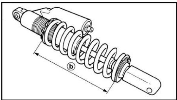
natural_image
Technical line drawing of a mechanical spring assembly with dimension label (b), no text or symbols present- Extent of adjustment (spring length)
| SPRING FREE LENGTH | EXTENT OF ADJUSTMENT 6 |
| 260mm (10.24in) | 240.5~258.5mm(9.47~10.18in) |
| 275mm (10.83in) | 255.5~273.5mm(10.06~10.77in) |
9If any of the following symptoms is experienced with the standard position as the base, make resetting by reference to the adjustment procedure given in the same chart.
9Before any change, set the rear shock absorber sunken length to the standard figure 90\~100 mm (3.5\~3.9 in).
| Symptom | Jump | Section | ||||
| Large gap | Medium gap | Small gap | Check | Adjust | ||
| Stiff over entire range | 1 | 1 | 1 | Compression damping Turn adjuster counterclockwise (about 2 clicks) to decrease damping. | ||
| Oil level (oil amount) Decrease oil level by about 5~10 mm (0.2~0.4 in). | ||||||
| Spring Replace with soft spring. | ||||||
| Unsmooth movement over 1 entire range | 1 | 1 | 1 | Outer tube Check for any bends, dents, and other notice-Inner tube able scars, etc. If any, replace affected parts.Under bracket tightening torque Retighten to specified torque. | ||
| Poor initial movement | Rebound damping Turn adjuster counterclockwise (about 2 clicks) 1 to decrease damping.Oil seal Apply grease in oil seal wall. | |||||
| Compression damping Turn adjuster clockwise (about 2 clicks) to in- | ||||||
| Soft over entire crease damping. range, bottoming out | 1 | 1 | Oil level (oil amount) Increase oil level by about 5~10 mm (0.2~0.4 in). | |||
| Spring Replace with stiff spring. | ||||||
| Stiff toward stroke end | 1 | Oil level (oil amount) Decrease oil level by about 5 mm (0.2 in). | ||||
| Soft toward stroke end, bottoming out | 1 | Oil level (oil amount) Increase oil level by about 5 mm (0.2 in). | ||||
| Stiff initial movement | 1 | 1 | 1 | 1 | Compression damping Turn adjuster counterclockwise (about 2 clicks) to decrease damping. | |
| Compression damping Turn adjuster counterclockwise (about 2 clicks) to decrease damping. | ||||||
| Low front, tending to lower front posture | 1 | 1 | Rebound damping Turn adjuster counterclockwise (about 2 clicks) to decrease damping. | |||
| Balance with rear end Set sunken length for 95~100 mm (3.7~3.9 in) when one passenger is astride seat (lower rear posture). | ||||||
| Oil level (oil amount) Increase oil level by about 5 mm (0.2 in). | ||||||
| Compression damping Turn adjuster counterclockwise (about 2 clicks) to decrease damping. | ||||||
| “Obtrusive” front, tending to upper front posture | 1 | 1 | Balance with rear end Set sunken length for 90~95 mm (3.5~3.7 in) when one passenger is astride seat (upper rear posture). | |||
| Spring Replace with soft spring. | ||||||
| Oil lever (oil amount) Decrease oil level by about 5~10 mm (0.2~0.4 in). | ||||||
•Rear shock absorber
NOTE:
- If any of the following symptoms is experienced with the standard position as the base, make resetting by reference to the adjustment procedure given in the same chart.
- Adjust the rebound damping in 2-click increments or decrements.
- Adjust the low compression damping in 1-click increments or decrements.
- Adjust the height compression damping in 1/6 turn increments or decrements.
| Symptom | Section | Check | Adjust | |||
| Jump | Large gap | Medium gap | Small gap | |||
| Stiff, tending to sink Spring set length | Set sunken | length for 90~100 mm (3.5~3.9 in) | Rebound damping Turn | adjuster counterclockwise (about 2 clicks) to decrease damping.when one passenger is astride seat. | ||
| Spongy and unstable | ○ | ○ | Rebound damping TurnLow compression Turn damping crease damping.Spring Replace with stiff spring. | adjuster clockwise (about 2 clicks) to increase damping.adjuster clockwise (about 1 click) to in- | ||
| Heavy and dragging | ○ | ○ | Rebound damping Turn to decrease damping.Spring Replace with soft spring. | adjuster counterclockwise (about 2 clicks) | ||
| Poor road gripping | ○ | Rebound damping TurnLow compression Turn damping crease damping.High compression damping increase damping.Spring set length Set sunken length for 90~100 mm (3.5~3.9 in)when one passenger is astride seat.Spring Replace with soft spring. | adjuster counterclockwise (about 2 clicks) to decrease damping.adjuster clockwise (about 1 click) to in-Turn adjuster clockwise (about 1/6 turn) to | |||
| Bottoming out | ○ | ○ | High compression damping crease damping.Spring set lengthSpring Replace with stiff spring. | Turn adjuster clockwise (about 1/6 turn) to in-Set sunken length for 90~100 mm (3.5~3.9 in) when one passenger in astride seat. | ||
| Bouncing | ○ | ○ | Rebound damping TurnSpring Replace with soft spring. | adjuster clockwise (about 2 clicks) to increase damping. | ||
| Stiff travel | ○ | ○ | High compression damping turn) to decreaseSpring set lengthSpring Replace with soft spring. | Turn adjuster counterclockwise (about 1/6 damping.Set sunken length for 90~100 mm (3.5~3.9 in) when one passenger is astride seat. | ||
- OWNER'S SERVICE MANUAL
- MANUEL D'ATELIER DU
- PROPRIETAIRE
- FAHRER-UND
- WARTUNGS-HANDBUCH
- NOTE:
- WARNING
- INTRODUCTION
- SAFETY INFORMATION
- NOTICE IMPORTANTE
- NOTICE
- F.I.M. MACHINE WEIGHTS:
- Weights of machines without fuel
- AU NOUVEAU PROPRIETAIRE
- CAUTION:
- FINDING THE REQUIRED PAGE
- COMMENT UTILISER CE MANUEL
- INFORMATIONS PARTICULIEREMENT IMPORTANTES
- HOW TO READ DESCRIPTIONS
- FORMAT DU MANUEL
- ILLUSTRATED SYMBOLS (Refer to the illustration)
- SYMBOLES GRAPHIQUES (Voir l'illustration)
- CHAPTER 2
- SPECIFICATIONS
- CHAPTER 3
- REGULAR INSPECTION
- AND ADJUSTMENTS
- TABLES DES MATIERES
- CHAPITRE 1 RENSEIGNEMENTS GENERAUX
- CHAPITRE 2 CARACTERISTIQUES
- CHAPITRE 3 VERIFICATION ET REGLAGES COURANTS
- INHALTSVERZEICHNIS
- CHAPTER 5 CHASSIS
- CHAPITRE 4 MOTEUR
- KAPITEL 4 MOTOR
- CHAPITRE 7 MISE AU POINT
- RENSEIGNEMENTS GENERAUX
- DESCRIPTION
- VEHICLE IDENTIFICATION NUMBER (For USA, CDN, AUS, NZ and E)
- FRAME SERIAL NUMBER
- (For F, D, GB, I and ZA)
- ENGINE SERIAL NUMBER
- MODEL LABEL
- IDENTIFICATION DE LA MACHINE
- IMPORTANT INFORMATION
- PREPARATION FOR REMOVAL AND DISASSEMBLY
- INFORMATIONS IMPORTANTES
- PREPARATION POUR LA DEPO- SE ET DEMONTAGE
- ALL REPLACEMENT PARTS
- GASKETS, OIL SEALS AND O-RINGS
- LOCK WASHERS/PLATES AND COTTER PINS
- BEARINGS AND OIL SEALS
- PIECES DE RECHANGE
- CIRCLIPS
- CHECKING OF CONNECTION
- VÉRIFICATION DES CONNEXIONS
- OUTILS SPECIAUX
- CONTROL FUNCTIONS
- "ENGINE STOP" BUTTON
- CLUTCH LEVER
- SHIFT PEDAL
- KICK STARTER
- THROTTLE GRIP
- FONCTIONS DES COMMANDES
- BOUTON D'ARRET DE MOTEUR "ENGINE STOP"
- FRONT BRAKE LEVER
- REAR BRAKE PEDAL
- FUEL COCK
- STARTER KNOB (CHOKE)
- LEVIER DE FREIN AVANT
- DETACHABLE SIDESTAND
- VALVE JOINT
- COLLAR (tool for YPVS)
- NIPPLE WRENCH
- BEQUILLE LATERALE AMOVIBLE
- ESSENCE ET HUILE DE MELANGE DU MOTEUR
- STARTING A COLD ENGINE
- STARTING A WARM ENGINE
- PROCEDURE DE RODAGE
- ATTENTION:
- POINTS DE VERIFICATION DE COUPLE DE SERRAGE
- CLEANING AND STORAGE
- CLEANING
- NETTOYAGE ET
- RANGEMENT
- NETTOYAGE
- MAINTENANCE SPECIFICATIONS
- GENERAL TORQUE SPECIFICATIONS
- DEFINITION OF UNITS
- CARACTERISTIQUES
- CARACTERISTIQUES GENERALES
- SCHEMA DE CHEMINEMENT DES CABLES
- SCHEMA DE CHEMINEMENT DES CABLES KABELFÜHRUNGSÜBERSICHTPLAN DIAGRAMMA DEL PASSAGGIO DEI CAVI
- VERIFICATION ET REGLAGES COURANTS PROGRAMME D'ENTRETIEN
- INSPECTION ET ENTRETIEN AVANT UTILISATION
- ENGINE
- COOLANT LEVEL INSPECTION
- COOLANT REPLACEMENT
- MOTEUR
- VERIFICATION DU NIVEAU DU LIQUIDE DE REFROIDISSEMENT
- AVERTISSEMENT
- Handling notes of coolant:
- Install:
- Check:
- EC355000
- RADIATOR CAP INSPECTION
- Inspect:
- RADIATOR CAP OPENING PRESSURE INSPECTION
- COOLING SYSTEM INSPECTION
- VERIFICATION DE LA PRESSION D'OUVERTURE DU BOUCHON DU RADIATEUR
- Inspect:
- CLUTCH ADJUSTMENT
- Check:
- Adjust:
- Clutch lever free play adjustment steps:
- N.B.:
- THROTTLE CABLE ADJUSTMENT
- Throttle grip free play adjustment steps:
- THROTTLE LUBRICATION
- Remove:
- Apply:
- REGLAGE DU CABLE
- D'ACCELERATION
- Clean:
- Monter:
- EC35H002
- TRANSMISSION OIL LEVEL CHECK
- CONTROLE DU NIVEAU DE L'HUILE DE BOITE DE VITESSES PRÜFUNG DES GETRIEBEÖLSTANDES CONTROLLO DEL LIVELLO DELL'OLIO DELLA TRASMISSIONE
- Check:
- Transmission oil level checking steps:
- Recommended oil:
- Oil check bolt:
- EC35K002
- TRANSMISSION OIL REPLACEMENT
- CHANGEMENT DE L'HUILE DE BOITE DE VITESSES ERNEUERUNG DES GETRIEBEÖLS SOSTITUZIONE DELL'OLIO DELLA TRASMISSIONE
- INSP ADJ
- [NO TEXT]
- Contrôler:
- Remove:
- Install:
- Fill:
- Check:
- Install:
- EC35L002
- PILOT AIR SCREW ADJUSTMENT
- Adjust:
- Adjustment steps:
- Déposer:
- EC35M010
- IDLE SPEED ADJUSTMENT
- EC35P030
- MUFFLER INSPECTION
- EC35R050
- SILENCER FIBER REPLACEMENT
- CHANGEMENT DE FIBRE DU SILENCIEUX ERNEURUNG DES SCHALLDÄMPFER-FASEREINSATZES SOSTITUZIONE DELLA FIBRA DEL SILENZIATORE
- Bleed the brake system if:
- Air bleeding steps:
- Bleed screw:
- Nm (0.6 m•kg, 4.3 ft•lb)
- PARTIE CYCLE/PURGE DE L'AIR DU SYSTEME DE FREINAGE FAHRGESTELL/ENTLÜFTUNG DER BREMSANLAGE TELAIO/SPURGO DELL'ARIA DALL'IMPIANTO FRENANTE
- PARTIE CYCLE
- !AVERTISSEMENT
- Install:
- Brake lever position adjustment steps:
- Pedal height adjustment steps:
- FRONT BRAKE PAD INSPECTION AND REPLACEMENT
- Brake pad replacement steps:
- REGLAGE DU FREIN ARRIERE
- Bolt (caliper):
- Pad pin:
- VERIFICATION ET CHANGEMENT DE LA PLAQUETTE DE FREIN AVANT INSPEKTION UND ERNEUERUNG DES VORDERRAD-BREMSBELAGPLATTE ISPEZIONE E SOSTITUZIONE DELLE PASTIGLIE DEL FRENO ANTERIORE
- Inspect:
- Check:
- REAR BRAKE PAD INSPECTION AND REPLACEMENT
- Replace:
- VERIFICATION ET CHANGEMENT DE LA PLAQUETTE DE FREINARRIERE INSPEKTION UND ERNEUERUNG DES HINTERRAD-BREMSBELAGPLATTE ISPEZIONE E SOSTITUZIONE DELLE PASTIGLIE DEL FRENO POSTERIORE
- Pad pin plug:
- Bolt (protector):
- REAR BRAKE PAD INSULATOR INSPECTION
- Recommended brake fluid: DOT #4
- VERIFICATION DE L'ISOLANT DE LA PLAQUETTE DE FREIN ARRIERE
- Déposer:
- SPROCKETS INSPECTION
- DRIVE CHAIN INSPECTION
- VERIFICATION DES PIGNONS
- DRIVE CHAIN SLACK ADJUSTMENT
- REGLAGE DE LA FLECHE DE CHAINE DE TRANSMISSION
- Adjust:
- Drive chain slack adjustment steps:
- To tighten →Turn adjuster ③counter-clockwise.
- To loosen →Turn adjuster ③clockwise and push wheel forward.
- EC36C000
- FRONT FORK INSPECTION
- VERIFICATION DE LA FOURCHE AVANT INSPEKTION DER VORDERRADGABEL ISPEZIONE DELLA FORCELLA ANTERIORE
- Régler:
- FRONT FORK OIL SEAL AND DUST SEAL CLEANING
- FRONT FORK INTERNAL PRESSURE RELIEVING
- FRONT FORK REBOUND DAMPING FORCE ADJUSTMENT
- Extent of adjustment:
- Standard position:
- FRONT FORK COMPRESSION DAMPING FORCE ADJUSTMENT
- REAR SHOCK ABSORBER INSPECTION
- VERIFICATION DE L'AMORTISSEUR ARRIERE INSPEKTION DES HINTERRAD-STOSSDÄMPFERS ISPEZIONE DELL'AMMORTIZZATORE POSTERIORE
- REAR SHOCK ABSORBER SPRING PRELOAD ADJUSTMENT
- REGLAGE DE LA PRECON- TRAINTE DE RESSORT DE L'AMORTISSEUR ARRIERE
- REGOLAZIONE DEL PRECARICO DELLA MOLLA DELL'AMMOR- TIZZATORE POSTERIORE
- •STANDARD POSITION:
- REAR SHOCK ABSORBER LOW COMPRESSION DAMPING FORCE ADJUSTMENT
- REGLAGE DE LA FORCE D'AMORTISSEMENT DE COMPRESSION BASSE DE L'AMORTISSEUR ARRIERE
- Régler:
- REAR SHOCK ABSORBER HIGH COMPRESSION DAMPING FORCE ADJUSTMENT
- REGLAGE DE LA FORCE D'AMORTISSEMENT DE COMPRESSION ELEVEE DE L'AMORTISSEUR ARRIERE
- TIRE PRESSURE CHECK
- SPOKES INSPECTION AND TIGHTENING
- WHEEL INSPECTION
- CONTROLE DE PRESSION DES PNEUS
- STEERING HEAD INSPECTION AND ADJUSTMENT
- Steering ring nut adjustment steps:
- Ring nut wrench: YU-33975/90890-01403
- VERIFICATION ET REGLAGE DE LA TETE DE FOURCHE INSPEKTION UND EINSTELLUNG DES LENKERKOPFES ISPEZIONE E REGOLAZIONE DELLA TESTA DI STERZO
- Examiner:
- GRAISSAGE
- ELECTRICAL
- SPARK PLUG INSPECTION
- PARTIE ELECTRIQUE/VERIFICATION DE LA BOUGIE ELEKTRISCHE EINRICHTUNGEN/INSPEKTION DER ZÜNDKERZE PARTE ELETTRICA/ ISPEZIONE DELLA CANDELA
- PARTIE ELECTRIQUE VERIFICATION DE LA BOUGIE
- IGNITION TIMING CHECK
- CONTROLE ET REGLAGE DE L'AVANCE A L'ALLUMAGE
- Adjust:
- CONTROLE ET REGLAGE DE L'AVANCE A L'ALLUMAGE PRÜFUNG UND EINSTELLUNG DER ZÜNDZEITPUNKT CONTROLLO DELLA MESSA IN FASE DELL'ACCENSIONE
- Régler:
- SELLE, RESERVOIR A ESSENCE ET COUVERCLES LATERAUX
- REMOVAL POINTS
- Side cover
- SELLE, RESERVOIR A ESSENCE ET COUVERCLES LATERAUX SITZ, KRAFTSTOFFTANK UND SEITENDECKEL SELLA, SERBATOIO DEL CARBURANTE E COPERTURE LATERALI
- POINTS DE DEPOSE
- Couvercle latéral
- TUYAU D'ECHAPPEMENT ET SILENCIEUX
- RADIATEUR
- INSPECTION
- Radiator
- REMARQUES CONCERNANT LA MANIPULATION
- ⚠ AVERTISSEMENT
- ASSEMBLY AND INSTALLATION
- REMONTAGE ET MONTAGE
- CARBURETOR AND REED VALVE
- CARBURATEUR ET SOUPAPE FLEXIBLE
- DEMONTAGE DU CARBURATEUR
- HANDLING NOTE
- Throttle valve
- Carburetor
- Inspect:
- Needle valve
- Jet needle
- CARBURATEUR ET SOUPAPE FLEXIBLE VERGASER UND ZUNGENVENTIL CARBURATORE E VALVOLA A LAMELLA
- Filter
- Fuel level
- Fuel level:
- Measurement and adjustment steps:
- Fuel level gauge adapter:
- Filtre
- Float
- Reed valve
- Flotteur
- Install:
- EC4652C2
- Install:
- Note the following installation points:
- Pilot air screw:
- Monter:
- Install:
- Install:
- Install:
- EC465352
- Carburetor installation
- Monter:
- Tighten:
- Clamp:
- Adjust:
- Serrer:
- PISTON ET CLAPET DE PUISSANCE
- Push rod
- Piston and piston ring
- Cylinder head
- Warpage measurement and re-surface-ment steps:
- Warpage limit: 0.03 mm(0.0012 in)
- Cylinder
- VERIFICATION
- Culasse
- Piston
- CULASSE, CYLINDRE ET PISTON ZYLINDERKOPF, ZYLINDER UND KOLBEN TESTA CILINDRO, CILINDRO E PISTONE
- Piston pin and small end bearing
- Piston ring
- Piston clearance
- Segment
- Monter:
- EC474700
- Combination of piston and cylinder
- Check:
- Combination:
- Power valve
- Power valve hole on cylinder
- Clapet de puissance
- Examiner:
- CULASSE, CYLINDER ET PISTON ZYLINDERKOPF, ZYLINDER UND KOLBEN TESTA CILINDRO, CILINDRO E PISTONE
- Piston ring and piston
- Segment et piston
- Cylinder head and cylinder
- Culasse et cylindre
- Appliquer:
- ENG
- Monter:
- Installare:
- CLUTCH AND PRIMARY DRIVEN GEAR EC498000
- CLUTCH PLATE AND FRICTION PLATE
- EMBRAYAGE ET PIGNON MENE PRIMAIRE DISQUE D'EMBRAYAGE ET DISQUE DE FRICTION
- PIGNON MENE PRIMAIRE
- Clutch boss
- Clutch housing and boss
- Primary driven gear
- Clutch spring
- EMBRAYAGE ET PIGNON MENE PRIMAIRE KUPPLUNG UND PRIMÄRABTRIEBSZAHNRAD FRIZIONE E INGRANAGGIO CONDOTTO PRIMARIO
- Noix d'embrayage
- Friction plate
- Measure:
- Clutch plate
- Push lever and push rod
- Clutch cover
- Disque de friction
- Mesurer:
- Clutch
- Embrayage
- N.B:
- HINWEIS:
- NOTA:
- Push lever
- KICK AXLE, SHIFT SHAFT AND PRIMARY DRIVE GEAR
- EC4C8000 PRIMARY DRIVE GEAR
- AXE DE DEMARREUR AU PIED, ARBRE DE SELECTEUR ET PIGNON DE TRANSMISSION PRIMAIRE PIGNON DE TRANSMISSION PRIMAIRE
- KICK AXLE AND SHIFT SHAFT
- AXE DE DEMARREUR AU PIED ET ARBRE DE SELECTEUR
- Primary drive gear
- Kick axle assembly
- Shift guide and shift lever assembly
- Kick axle and kick gear
- Kick gear and kick idle gear
- Pignon de transmission primaire
- Kick gear clip
- Shift shaft
- Stopper lever
- Primary drive gear and primary driven gear
- Levier de butée
- EC4C5301
- EC4B5302
- AXE DE DEMARREUR AU PIED, ARBRE DE SELECTEUR ET PIGNON DE TRANSMISSION PRIMAIRE KICKSTARTERWELLE, SCHALTWELLE UND PRIMÄRANTRIEBSZAHNRAD PEDIVELLA, ALBERO DEL CAMBIO E INGRANAGGIO CONDUTTORE PRIMARIO
- Kick idle gear
- Check:
- REGULATEUR YPVS
- Governor
- Governor groove
- Bearing
- Régulateur
- POMPE A EAU
- Impeller shaft
- Oil seal
- Axe de turbine
- Impeller shaft gear
- MAGNETO CDI
- Rotor
- CDI magneto
- Woodruff key
- Tighten:
- Check:
- Kontrollieren:
- Connect:
- Connector:
- Drive sprocket
- Engine removal
- Engine installation
- Brake pedal
- Montage du moteur
- CRANKCASE AND CRANKSHAFT
- Crankcase
- Crankcase separating tool: YU-1135-A/90890-01135
- Crankshaft bearing
- Vilebrequin
- EC4N4202
- Crankshaft
- EC4N5000
- EC4N5300
- CARTER ET VILEBREQUIN KURBELGEHÄUSE UND KURBELWELLE CARTER E ALBERO A GOMITI
- Crankshaft installing tool:
- Bague d'étanchéité
- Apply:
- Contrôler:
- Remove:
- Apply:
- Check:
- Monter:
- Einbauen:
- Installare:
- TRANSMISSION, SHIFT CAM AND SHIFT FORK
- BOITE A VITESSES, BARILLET DE SELECTEUR ET FOURCHETTE GETRIEBE, SCHALTNOCKE UND SCHALTGABEL TRASMISSIONE, CAMMA DEL CAMBIO E FORCELLA DEL CAMBIO
- BOITE A VITESSES, BARILLET DE SELECTEUR ET FOURCHETTE
- Transmission
- Gears
- Boîte à vitesses
- Shift fork, shift cam and segment
- EC4H5312
- Shift cam and shift fork
- Contrôler:
- ROUE AVANT ET ROUE ARRIERE
- ROUE AVANT
- ROUE ARRIERE
- Rear wheel
- Wheel bearing (if necessary)
- Wheel
- Wheel runout limit:
- Wheel axle
- Brake disc
- ROUE AVANT ET ROUE ARRIERE VORDERRAD UND HINTERRAD RUOTA ANTERIORE E RUOTA POSTERIORE
- Axe de roue
- Front wheel
- EC5251A1
- Monter:
- Adjust:
- Tighten:
- Monter:
- FREIN AVANT ET FREIN ARRIERE
- FREIN AVANT
- FREIN ARRIERE
- DEMONTAGE DE L'ETRIER
- DEMONTAGE DU MAITRE-CYLINDRE
- Brake fluid
- Caliper piston
- Caliper piston removal steps:
- Liquide de frein
- Piston seal kit
- Master cylinder
- Use only new brake fluid.
- FREIN AVANT ET FREIN ARRIERE VORDERRADBREMSE UND HINTERRADBREMSE FRENO ANTERIORE E FRENO POSTERIORE
- Caliper
- Brake hose
- Etrier
- Front caliper
- Rear caliper
- Tighten:
- Master cylinder kit
- Clean:
- EC5A5310
- Front master cylinder
- Rear master cylinder
- FREIN AVNAT ET FREIN ARRIERE VORDERRADBREMSE UND HINTERRADBREMSE FRENO ANTERIORE E FRENO POSTERIORE
- EC5A5911
- Front brake hose
- Rear brake hose
- FREIN AVANT ET FREIN ARRIERE VORDERRADBREMSE AND HINTERRADBREMSE FRENO ANTERIORE E FRENO POSTERIORE
- Fill:
- Purger de l'air:
- FOURCHE AVANT
- DEMONTAGE DE LA FOURCHE AVANT
- Cap bolt
- REMARQUES
- CONCERNANT LA
- MANIPULATION
- Inner tube
- Oil seal removal steps:
- Damper rod
- Damper rod holder: YM-1423/90890-01423
- Tube interne
- Base valve
- Fork spring
- Outer tube
- Soupare de base
- Ressort de fourche
- Front fork assembly
- Boulon capuchon
- Hutschraube
- Contrôler:
- Measure:
- Distance ⓐ:
- Loosen:
- Install:
- Install:
- Install:
- Mesurer:
- Installation
- Serrer:
- Serrer:
- GUIDON
- DEMONTAGE DE L'ACCELERATEUR
- Grip
- Handlebar
- Throttle assembly
- Maître-cylindre
- AVVERTENZA
- EC5B5210
- Monter:
- Install:
- Install:
- Install:
- Adjust:
- STEERING
- DIRECTION
- Ring nut
- Bearing (lower)
- Ball race
- Steering shaft
- Ecrou annulaire
- Bearing and ball race
- Under bracket
- BRAS OSCILLANT
- DEMONTAGE DU BRAS OSCILLANT
- Swingarm
- Relay arm
- Roulement
- Connecting rod
- Bearing and oil seal
- Bielle
- Tighten:
- Contrôler:
- Kontrollieren:
- Controllare:
- Serrer:
- Festziehen:
- Serrare:
- AMORTISSEUR ARRIERE
- NOTES ON DISPOSAL (YAMAHA DEALERS ONLY)
- ⚠AVERTISSEMENT
- Rear shock absorber
- Spring (rear shock absorber)
- AMORTISSEUR ARRIERE HINTERRAD-STOSSDÄMPFER AMMORTIZZATORE POSTERIORE
- WIRING DIAGRAM
- PARTIE ELETRIQUE COMPOSANTS ELECTRIQUES ET SCHEMA DE CABLAGE COMPOSANTS ELECTRIQUES
- SYSTEME D'ALLUMAGE ETAPES DE VERIFICATION
- SISTEMA DI ACCENSIONE
- EC622001
- SPARK GAP TEST
- EC624000
- COUPLERS AND LEADS CONNECTION INSPECTION
- EC625002
- "ENGINE STOP" BUTTON INSPECTION
- ESSAI DE L'INTERVALLE D'ETINCELLEMENT D'ALLUMAGE
- ACCOPPIATORI E CONDUTTORI
- IGNITION COIL INSPECTION
- VERIFICATION DE LA BOBINE D'ALLUMAGE
- SPARK PLUG CAP INSPECTION
- 1.Inspect:
- CDI MAGNETO INSPECTION
- INSPECTION DU CAPUCHON DE BOUGIE
- CDI UNIT INSPECTION
- Examiner:
- Atmospheric conditions and carburetor setting
- MISE AU POINT MOTEUR
- Test run
- Ainsi:
- Effect of setting parts in relation to throttle valve opening
- Main jet adjustment
- Pilot jet adjustment
- Jet needle groove position adjustment
- Jet needle adjustment
- (For USA, CDN, ZA, AUS and NZ)
- Standard jet needle 6CHY6-82
- Jet needle adjustment (For EUROPE)
- Relationship with throttle opening
- Change of the heat range of spark plugs
- - Standard rotor
- - Optional rotor
- Sélection du rotor
- Drive and driven sprockets setting parts
- Tire pressure
- Spring preload adjustment
- Setting of spring after replacement
- Use of stiff spring
- Ressort dur
- Front fork setting parts
- Rear suspension setting
- Choosing set length
- Rear shock absorber setting parts
Brand : YAMAHA
Model : YZ125LC
Category : Motorcycle