D102GGC2 - Motherboard INTEL - Free user manual and instructions
Find the device manual for free D102GGC2 INTEL in PDF.

User questions about D102GGC2 INTEL
0 question about this device. Answer the ones you know or ask your own.
Ask a new question about this device
Download the instructions for your Motherboard in PDF format for free! Find your manual D102GGC2 - INTEL and take your electronic device back in hand. On this page are published all the documents necessary for the use of your device. D102GGC2 by INTEL.
USER MANUAL D102GGC2 INTEL
Order Number: D47985-002
Revision History
| Revision | Revision History Date | |
| -001 | First release of the Intel ^ Desktop Board D102GGC2 Product Guide | February 2006 |
| -002 Second release of the Intel Desktop Board D102GGC2 Product Guide July 2006 | ||
If an FCC declaration of conformity marking is present on the board, the following statement applies:
FCC Declaration of Conformity
This device complies with Part 15 of the FCC Rules. Operation is subject to the following two conditions: (1) this device may not cause harmful interference, and (2) this device must accept any interference received, including interference that may cause undesired operation.
For questions related to the EMC performance of this product, contact:
Intel Corporation, 5200 N.E. Elam Young Parkway, Hillsboro, OR 97124, 1-800-628-8686
This equipment has been tested and found to comply with the limits for a Class B digital device, pursuant to Part 15 of the FCC Rules. These limits are designed to provide reasonable protection against harmful interference in a residential installation. This equipment generates, uses, and can radiate radio frequency energy and, if not installed and used in accordance with the instructions, may cause harmful interference to radio communications. However, there is no guarantee that interference will not occur in a particular installation. If this equipment does cause harmful interference to radio or television reception, which can be determined by turning the equipment off and on, the user is encouraged to try to correct the interference by one or more of the following measures:
- Reorient or relocate the receiving antenna.
- Increase the separation between the equipment and the receiver.
- Connect the equipment to an outlet on a circuit other than the one to which the receiver is connected.
- Consult the dealer or an experienced radio/TV technician for help.
Any changes or modifications to the equipment not expressly approved by Intel Corporation could void the user's authority to operate the equipment.
Tested to comply with FCC standards for home or office use.
Canadian Department of Communications Compliance Statement
This digital apparatus does not exceed the Class B limits for radio noise emissions from digital apparatus set out in the Radio Interference Regulations of the Canadian Department of Communications.
Information in this document is provided in connection with Intel® products. No license, express or implied, by estoppel or otherwise, to any intellectual property rights is granted by this document. Except as provided in Intel's Terms and Conditions of Sale for such products, Intel assumes no liability whatsoever, and Intel disclaims any express or implied warranty, relating to sale and/or use of Intel products including liability or warranties relating to fitness for a particular purpose, merchantability, or infringement of any patent, copyright or other intellectual property right. Intel products are not intended for use in medical, life saving, or life sustaining applications. Intel may make changes to specifications and product descriptions at any time, without notice.
Desktop Board D102GGC2 may contain design defects or errors known as errata which may cause the product to deviate from published specifications. Current characterized errata are available on request.
Contact your local Intel sales office or your distributor to obtain the latest specifications and before placing your product order.
Copies of documents which have an ordering number and are referenced in this document, or other Intel literature, may be obtained from Intel Corporation by going to the World Wide Web site at: http://www.intel.com/ or by calling 1-800-548-4725.
Intel, the Intel logo, Pentium, and Celeron are registered trademarks of Intel Corporation or its subsidiaries in the United States and other countries.
* Other names and brands may be claimed as the property of others.
Copyright © 2006, Intel Corporation. All rights reserved.
Preface
This Product Guide gives information about board layout, component installation, and regulatory requirements for Intel ^® Desktop Board D102GGC2.
Intended Audience
The Product Guide is intended for technically qualified personnel. It is not intended for general audiences.
Intended Uses
All Intel desktop boards are evaluated as Information Technology Equipment (I.T.E.) for use in personal computers (PC) for installation in homes, offices, schools, computer rooms, and similar locations. The suitability of this product for other PC or embedded non-PC applications or other environments, such as medical, industrial, alarm systems, test equipment, etc. may not be supported without further evaluation by Intel.
Document Organization
The chapters in this Product Guide are arranged as follows:
1 Desktop Board Features: a summary of product features
2 Installing and Replacing Desktop Board Components: instructions on how to install the desktop board and other hardware components
3 Updating the BIOS: information about how to update the BIOS
A Error Messages and Indicators: information about BIOS error messages and beep codes
B Regulatory Compliance: safety and EMC regulations, product certification
Conventions
The following conventions are used in this manual:

CAUTION
Cautions warn the user about how to prevent damage to hardware or loss of data.

NOTE
Notes call attention to important information.
Terminology
The table below gives descriptions to some common terms used in the product guide.
| Term | Description | ||
| GB Gigabyte (1,073,741,824 bytes) | |||
| GHz Gigahertz (one billion hertz) | |||
| KB Kilobyte (1024 bytes) | |||
| MB | Megabyte | (1,048,576 | bytes) |
| Mbit Megabit (1,048,576 bits) | |||
| MHz Megahertz | (one million hertz) | ||
Box Contents
- Intel Desktop Board
- I/O shield
• One ATA-66/100 cable
• One Serial ATA cable
• One diskette drive cable - Quick Reference poster
- Configuration and battery caution statement label
- Intel ^ Express Installer driver CD-ROM
1 Desktop Board Features
Supported Operating Systems 10
Desktop Board Components ....11
Processor....13
Main Memory 13
ATI RADEON* XPRESS 200 Chipset....14
Graphics Subsystem....14
Audio Subsystem....14
Input/Output (I/O) Controller 15
LAN Subsystem 15
LAN Subsystem Software....15
RJ-45 LAN Connector LEDs....16
Hi-Speed USB 2.0 Support....16
Enhanced IDE Interface 17
Serial ATA....17
Expandability....17
BIOS 17
Serial ATA and IDE Auto Configuration....17
PCI and PCI Express* Auto Configuration....17
Security Passwords....18
Chassis Intrusion....18
Power Management Features 18
ACPI....18
Power Connectors....18
Fan Connectors....19
Suspend to RAM (Instantly Available PC Technology) 19
Wake from USB....20
Wake from PS/2 Keyboard/Mouse....21
PME# Wakeup Support....21
Speaker....21
Battery....21
Real-Time Clock....21
2 Installing and Replacing Desktop Board Components
Before You Begin....23
Installation Precautions 24
Prevent Power Supply Overload....24
Observe Safety and Regulatory Requirements....24
Installing the I/O Shield 25
Installing and Removing the Desktop Board....26
Installing and Removing a Processor 27
Installing a Processor....27
Installing the Processor Fan Heat Sink....30
Connecting the Processor Fan Heat Sink Cable....30
Removing the Processor ....30
Installing and Removing Memory ....31
Installing DIMMs....31
Removing DIMMs....33
Installing and Removing a PCI Express x16 Card 34
Installing a PCI Express x16 Card 34
Removing the PCI Express x16 Card 35
Connecting the IDE Cable....36
Connecting the Serial ATA (SATA) Cable 37
Connecting Internal Headers....38
Installing a Front Panel Audio Solution 39
Connecting Hi-Speed USB 2.0 Headers....40
Connecting the Front Panel Header 40
Setting Up the Flexible 6-Channel Audio with Jack Re-tasking (Optional) 41
Connecting Chassis Fan Cables 42
Connecting Power Cables....43
Other Connectors....44
Setting the BIOS Configuration Jumper....45
Clearing Passwords 46
Replacing the Battery 47
3 Updating the BIOS
Updating the BIOS with the Intel® Express BIOS Update Utility....53
Updating the BIOS with the Iflash Memory Update Utility 53
Obtaining the BIOS Update File....53
Updating the BIOS....54
Recovering the BIOS....54
A Error Messages and Indicators
BIOS Beep Codes....55
BIOS Error Messages 55
B Regulatory Compliance
Safety Regulations....57
Place Battery Marking 57
European Union Declaration of Conformity Statement 58
Product Ecology Statements....59
Recycling Considerations....59
Lead-Free Desktop Board 61
EMC Regulations 62
Ensure Electromagnetic Compatibility (EMC) Compliance....63
Product Certifications....63
Board-Level Certification Markings....63
Chassis and Component Certifications....64
Figures
-
Intel Desktop Board D102GGC2 Components....11
-
LAN Connector LEDs....16
-
Location of the Standby Power Indicator....20
-
Installing the I/O Shield....25
-
Desktop Board D102GGC2 Mounting Screw Hole Locations....26
-
Lift Socket Lever....27
-
Lift the Load Plate and Don't Touch the Socket Contacts ....27
-
Remove the Protective Socket Cover ....28
-
Remove the Processor from the Protective Processor Cover/Do Not Touch.....28
-
Install Processor....29
-
Close the Load Plate ....29
-
Connecting the Processor Fan Heat Sink Cable to the Processor Fan Connector......30
-
Use DDR DIMMs....31
-
Installing a DIMM....32
-
Installing a PCI Express x16 Card ....34
-
Removing a PCI Express x16 Card....35
-
Connecting the IDE Cable 36
-
Connecting the Serial ATA Cable 37
-
Internal Headers ...... 38
-
Back Panel Audio Connectors for a Flexible 6-Channel Audio System ....41
-
Location of the Chassis Fan Headers 42
-
Connecting 2 x 12 Power Supply Cables....43
-
Location of Other Connectors on Desktop Board D102GGC2....44
-
Location of the BIOS Configuration Jumper Block 45
-
Removing the Battery ....51
Tables
-
Feature Summary......9
-
Desktop Boards D102GGC2 Components....12
-
Power Supply Requirements....13
-
RJ-45 10/100 Ethernet LAN Connector LEDs....16
-
Front Panel Audio Header Signal Names for High Definition Audio....39
-
AC '97 Audio Header Signal Names....39
-
Hi-Speed USB 2.0 Header Signal Names....40
-
Front Panel Header Signal Names....40
-
Jumper Settings for the BIOS Setup Program Modes 46
-
Beep Codes....55
-
BIOS Error Messages....55
-
Safety Regulations....57
-
Lead-Free Board Markings ....61
-
EMC Regulations....62
-
Product Certification Markings....63
1 Desktop Board Features
This chapter briefly describes the main features of Intel® Desktop Board D102GGC2. Table 1 summarizes the major features of the desktop board.
Table 1. Feature Summary
| Form Factor | MicroATX (243.84 millimeters [9.60 inches] x 218.44 millimeters [8.60 inches]) |
| Processor | Support for an Intel®processor in the LGA775 package |
| Main Memory | Two 240-pin SDRAM Dual Inline Memory Module (DIMM) sockets533/400 MHz single channel DDR2 SDRAM interfaceDesigned to support up to 2 GB of system memory |
| Chipset ATI RADEON* XPRESS 200 | ATI RADEON XPRESS NorthbridgeATI IXP 450 Southbridge |
| Graphics | ATI RADEON XPRESS 200 Graphics with support for external graphics via a PCI Express* x16 connector |
| Audio | ATI RADEON XPRESS 200 ChipsetHigh Definition Audio interfaceRealtek* codec |
| Expansion Capabilities | Two PCI bus add-in card connectorsOne PCI Express x16 connectorOne PCI Express x1 connector |
| Peripheral Interfaces | Eight USB 2.0 portsFour ports routed to the back panelFour ports routed to two USB headersFour Serial ATA (SATA) channels (1.5 Gb/s)Two IDE interfaces with ATA-100 support (four devices)One VGA connectorOne diskette drive interfaceOne parallel portOne serial portPS/2* keyboard and mouse ports |
| BIOS | Intel® BIOSSupport for SMBIOSIntel® Rapid BIOS BootIntel® Express BIOS Update |
| Power Management | Support for Advanced Configuration and Power Interface (ACPI)Suspend to RAM (STR)Wake on USB, PCI, PCI Express, PS/2, LAN, and front panel |
Related Links:
For more information about desktop board D102GGC2, including the Technical Product Specification (TPS), BIOS updates, and device drivers, go to:
http://support.intel.com/support/motherboards/desktop/
Supported Operating Systems
The desktop board supports the following operating systems:
- Microsoft Windows* XP Media Center Edition 2005
• Microsoft Windows XP Professional
• Microsoft Windows XP Professional x64 Edition
• Microsoft Windows XP Home
• Microsoft Windows 2000
Desktop Board Components
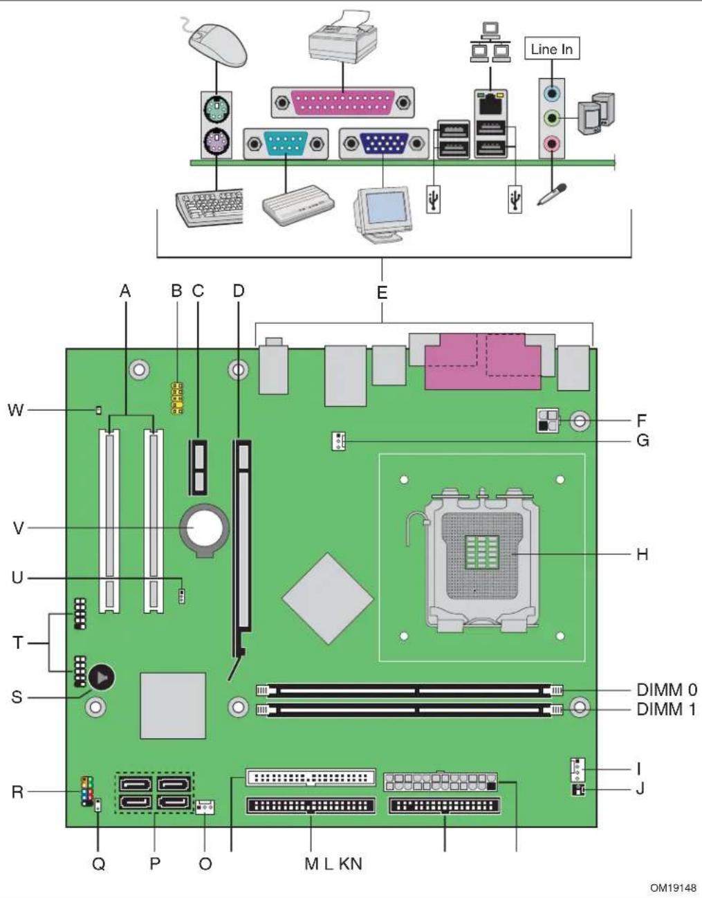
Figure 1 shows the approximate location of the major components on desktop board D102GGC2.
text_image
Line In A B C D E W F V G U H T H S DIMM 0 R DIMM 1 Q P O M L KN I J OM19148Figure 1. Intel Desktop Board D102GGC2 Components
Table 2. Desktop Boards D102GGC2 Components
| Label | Description |
| A PCI bus add-in card connectors | |
| B Front panel audio header | |
| C PCI Express* x1 connector | |
| D PCI Express x16 connector | |
| E Back panel connectors | |
| F 12 V processor core voltage connector (2 x 2) | |
| G Rear fan (3-pin) | |
| H | Processor socket |
| I Processor fan header (4-pin) | |
| J Chassis intrusion connector | |
| K Main power connector (2 x 12) | |
| L | Diskette drive connector |
| M Primary IDE connector | |
| N Secondary IDE connector | |
| O Front chassis fan header (3-pin) | |
| P Serial ATA connectors | |
| Q Alternate front panel power LED header | |
| R Front panel header | |
| S | Speaker |
| T Hi-speed USB 2.0 headers | |
| U BIOS configuration jumper | |
| V | Battery |
| W | Standby LED |
Related Links:
Go to the following links for more information about:
- Desktop board D102GGC2
http://www.intel.com/design/motherbd
http://support.intel.com/support/motherboards/desktop
http://support.intel.com/support/motherboards/desktop
http://www.intel.com/design/motherbd
http://www.intel.com/design/motherbd
• Supported processors
• Audio software and utilities
• LAN software and drivers
Processor

CAUTION
Failure to use the appropriate power supply (below) and/or not connecting the 12 V (2 x 2) power connector to the desktop board may result in damage to the board, or the system may not function properly.
Table 3. Power Supply Requirements
| Platform Compatibility Guide Power Supply Requirements |
| 05A 12V2 rating of 13 A continuous and 16.5 A peak current for 10 ms |
| 04A ATX12V (version 2.0 or greater) compliant power supply |
Desktop board D102GGC2 supports an Intel processor in the LGA775 package. Processors are not included with the desktop board and must be purchased separately. The processor connects to the desktop board through the LGA775 socket.
The supported processors list for desktop board D102GGC2 is located on the web at: http://support.intel.com/support/motherboards/desktop/
Related Links:
Go to the following links or pages for more information about:
- Instructions on installing or upgrading the processor, page 27 in Chapter 2
- The location of the two power connectors, page 43 in Chapter 2
Main Memory

NOTE
To be fully compliant with all applicable Intel ^® SDRAM memory specifications, the board should be populated with DIMMs that support the Serial Presence Detect (SPD) data structure. If your memory modules do not support SPD, you will see a notification to this effect on the screen at power up. The BIOS will attempt to configure the memory controller for normal operation.
The desktop board supports the memory configurations defined below:
- Two 240-pin Double Data Rate 2 (DDR2) SDRAM Dual Inline Memory Modules (DIMMs) connectors with gold-plated contacts
- Support for:
— Unbuffered, non-registered DIMMs
— Serial Presence Detect (SPD) memory only
— Non-ECC DDR2
— The following memory configurations:
Up to 1.0 GB utilizing 256 Mb technology
Up to 2.0 GB utilizing 512 Mb or 1 Gb technology
Related Links:
Go to the following links or pages for more information about:
- The latest list of tested memory, http://support.intel.com/support/motherboards/desktop/
- SDRAM specifications, http://www.intel.com/technology/memory/
• Installing memory, page 31 in Chapter 2
ATI RADEON\* XPRESS 200 Chipset
The ATI RADEON XPRESS 200 Chipset consists of the following devices:
• ATI RADEON XPRESS Northbridge
• ATI IXP 450 Southbridge
Graphics Subsystem
Desktop board D102GGC2 includes the following:
• ATI RADEON XPRESS 200 Chipset
- PCI Express x16 connector for graphics expansion
Audio Subsystem
Desktop board D102GGC2 includes a flexible 6-channel audio subsystem based on a High Definition Audio interface:
The audio subsystem features:
• ATI IXP 450 Southbridge
• Realtek AL803/ALC861 audio codec
- Impedance sensing capability for jack re-tasking
• S/N (signal-to-noise) ratio: 90 dB
• Microphone input supporting:
— Stereo microphone
— Microphone boost
The subsystem includes the following connectors:
- Front panel audio connector, including functionality for:
— Line out — Microphone in - Back panel audio connectors that are configurable through the drivers of the audio devices:
— Rear left/right out or Line In
— Front left/right out or Line Out
— Center/LFE out or Mic In
Related Links:
Go to the following link or pages for more information about:
• Audio drivers and utilities http://support.intel.com/support/motherboards/desktop/
- Installing the front panel audio solution, page 39 in Chapter 2
- The location of audio connectors, Figure 20 on page 41
Input/Output (I/O) Controller
The super I/O controller features the following:
- One serial port
- One parallel port with Extended Capabilities Port (ECP) and Enhanced Parallel Port (EPP) support
- Serial IRQ interface compatible with serialized IRQ support for PCI systems
• PS/2-style mouse and keyboard interfaces - Interface for one 1.2 MB or 1.44 MB diskette drive
- Intelligent power management, including a programmable wake up event interface
• PCI power management support
LAN Subsystem
The LAN provides the following functions:
- Basic 10/100 Ethernet LAN (Realtek 8101L controller)
• Support for RJ-45 connector with status indicator LEDs
• Programmable transit threshold - Configurable EEPROM that contains the MAC address
LAN Subsystem Software
For LAN software and drivers, refer to the D102GGC2 link on Intel's World Wide Web site at: http://support.intel.com/support/motherboards/desktop
RJ-45 LAN Connector LEDs
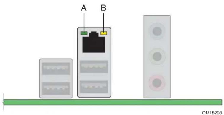
Two LEDs are built into the RJ-45 LAN connector located on the back panel (see Figure 2).
text_image
A B OM18208Figure 2. LAN Connector LEDs
Table 4 describes the LED states when the board is powered up and the 10/100 Ethernet LAN subsystem is operating.
Table 4. RJ-45 10/100 Ethernet LAN Connector LEDs
| LED | LED State | Indicates |
| Blinking LAN | Off LAN link is not established A (Green) | |
| On LAN link is established | ||
| Activity is occurring | ||
| Off 10 Mbits/s data rate is selected B (Yellow) | ||
| On (steady state) 100 Mbits/s data rate is selected |
Hi-Speed USB 2.0 Support

NOTE
Computer systems that have an unshielded cable attached to a USB port might not meet FCC Class B requirements, even if no device or a low-speed USB device is attached to the cable. Use a shielded cable that meets the requirements for a full-speed USB device.
The desktop board supports up to eight USB 2.0; four ports routed to the back panel and four routed to two internal USB 2.0 headers. USB 2.0 ports are backward compatible with USB 1.1 devices. USB 1.1 devices will function normally at USB 1.1 speeds.
USB 2.0 support requires both an operating system and drivers that fully support USB 2.0 transfer rates. Disabling Hi-Speed USB in the BIOS reverts all USB 2.0 ports to USB 1.1 operation. This may be required to accommodate operating systems that do not support USB 2.0.
Enhanced IDE Interface
The IDE interface handles the exchange of information between the processor and peripheral devices like hard disks, CD-ROM drives, and Iomega Zip* drives inside the computer. The interface supports:
- Up to four IDE devices (such as hard drives)
• ATAPI-style devices (such as CD-ROM drives) - Older PIO Mode devices
• Ultra DMA-33/66/100 modes
Serial ATA
The desktop board supports four Serial ATA channels (1.5 Gb/s), connecting one device per channel.
Expandability
The desktop board supports the following:
• One PCI Express x16 add-in card
• One PCI Express x1 add-in card
- Two PCI add-in cards
Related Links:
For information about installing the PCI Express x16 card, see page 34 in Chapter 2.
BIOS
The BIOS provides the Power-On Self-Test (POST), the BIOS Setup program, the PCI/PCI Express and IDE auto-configuration utilities, and the video BIOS.
Serial ATA and IDE Auto Configuration
If you install a Serial ATA or IDE device (such as a hard drive) in your computer, the auto-configuration utility in the BIOS automatically detects and configures the device for your computer. You do not need to run the BIOS Setup program after installing a Serial ATA or IDE device. You can override the auto-configuration options by specifying manual configuration in the BIOS Setup program.
PCI and PCI Express\* Auto Configuration
If you install a PCI/PCI Express add-in card in your computer, the PCI/PCI Express auto-configuration utility in the BIOS automatically detects and configures the resources (IRQs, DMA channels, and I/O space) for that add-in card. You do not need to run the BIOS Setup program after you install a PCI or PCI Express add-in card.
Security Passwords
The BIOS includes security features that restrict whether the BIOS Setup program can be accessed and who can boot the computer. A supervisor password and a user password can be set for the BIOS Setup and for booting the computer, with the following restrictions:
- The supervisor password gives unrestricted access to view and change all Setup options. If only the supervisor password is set, pressing
at the password prompt of Setup gives the user restricted access to Setup. - If both the supervisor and user passwords are set, you must enter either the supervisor password or the user password to access Setup. Setup options are then available for viewing and changing depending on whether the supervisor or user password was entered.
- Setting a user password restricts who can boot the computer. The password prompt is displayed before the computer is booted. If only the supervisor password is set, the computer boots without asking for a password. If both passwords are set, you can enter either password to boot the computer.
Related Links:
For instructions on resetting the password, see Clearing Passwords on page 46.
Chassis Intrusion
The board supports a chassis security feature that detects if the chassis cover has been removed. The security feature uses a mechanical switch on the chassis that can be connected to the chassis intrusion connector on the desktop board. See Figure 23 on page 44 for the location of the chassis intrusion connector.
Power Management Features
Power management is implemented at several levels, including:
- Advanced Configuration and Power Interface (ACPI)
- Hardware support:
— Power connectors
— Fan connectors
— Suspend to RAM (Instantly Available PC technology)
— Wake from USB
— Wake from PS/2 keyboard/mouse
— PME# wakeup support
ACPI
ACPI gives the operating system direct control over the power management and Plug and Play functions of a computer. The use of ACPI with the desktop board requires an operating system that provides full ACPI support.
Power Connectors
The desktop board has two power connectors. See Figure 22 on page 43 for the location of the power connectors.
Fan Connectors
The desktop board has a 4-pin processor fan header and two 3-pin chassis fan headers. See Figure 21 on page 42 for the location of the chassis fan headers.
Suspend to RAM (Instantly Available PC Technology)

CAUTIONS
For Instantly Available PC technology, the 5 V standby line for the power supply must be capable of delivering adequate +5 V standby current. Failure to provide adequate standby current when using this feature can damage the power supply and/or effect ACPI S3 sleep state functionality.
Power supplies used with this desktop board must be able to provide enough standby current to support the standard Instantly Available (ACPI S3 sleep state) configuration. If the standby current necessary to support multiple wake events from the PCI and/or USB buses exceeds power supply capacity, the desktop board may lose register settings stored in memory.
Instantly Available PC technology enables the board to enter the ACPI S3 (Suspend-to-RAM) sleep state. While in the S3 sleep state, the computer will appear to be off. When signaled by a wake-up device or event, the system quickly returns to its last known awake state.
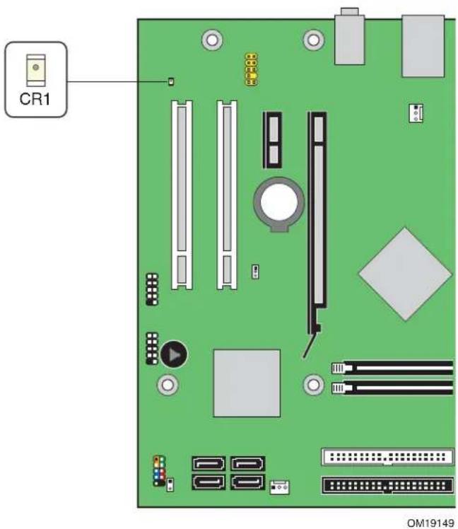
The desktop board's standby power indicator, shown in Figure 3, is lit when there is standby power to the system. This includes the memory modules and PCI bus connectors, even when the computer appears to be off.
If the system has a dual-colored power LED on the front panel, the sleep state is indicated by the LED turning amber.
text_image
CR1 OM19149Figure 3. Location of the Standby Power Indicator
Related Links:
For more information on standby current requirements for the desktop board, refer to the Technical Product Specification by going to the following link, finding the product, and selecting Product Documentation from the left-hand menu:
http://support.intel.com/support/motherboards/desktop/
Wake from USB

NOTE
Wake from USB requires the use of a USB peripheral that supports wake from USB.
USB bus activity wakes the computer from an ACPI S1 or S3 state.
Wake from PS/2 Keyboard/Mouse
PS/2 keyboard/mouse activity wakes the computer from an ACPI S1 or S3 state.
PME# Wakeup Support
When the PME# signal on the PCI bus is asserted, the computer wakes from an ACPI S1, S3, or S5 state.
Speaker
A speaker is mounted on the desktop board. The speaker provides audible error code (beep code) information during the Power-On Self-Test (POST).
Battery
A battery on the desktop board keeps the values in CMOS RAM and the clock current when the computer is turned off. Go to page 47 for instructions on how to replace the battery.
Real-Time Clock
The desktop board has a time-of-day clock and 100-year calendar. The battery on the desktop board keeps the clock current when the computer is turned off.
2 Installing and Replacing Desktop Board Components
This chapter tells you how to:
• Install the I/O shield
• Install and remove the desktop board
• Install and remove a processor and memory
• Install and remove a PCI Express x16 card
- Connect the IDE and Serial ATA cables
- Connect internal headers
- Set up flexible 6-channel audio with jack re-tasking
- Connect fans and power cables
- Locate other connectors
- Set the BIOS configuration jumper
- Clear passwords
- Replace the battery
Before You Begin

CAUTIONS
The procedures in this chapter assume familiarity with the general terminology associated with personal computers and with the safety practices and regulatory compliance required for using and modifying electronic equipment.
Disconnect the computer from its power source and from any telecommunications links, networks, or modems before performing any of the procedures described in this chapter. Failure to disconnect power, telecommunications links, networks, or modems before you open the computer or perform any procedures can result in personal injury or equipment damage. Some circuitry on the board can continue to operate even though the front panel power button is off.
Follow these guidelines before you begin installing the desktop board:
• Always follow the steps in each procedure in the correct order.
- Set up a log to record information about your computer, such as model, serial numbers, installed options, and configuration information.
- Electrostatic discharge (ESD) can damage components. Perform the procedures described in this chapter only at an ESD workstation using an antistatic wrist strap and a conductive foam pad. If such a station is not available, you can provide some ESD protection by wearing an antistatic wrist strap and attaching it to a metal part of the computer chassis.
Installation Precautions
When you install and test the Intel desktop board, observe all warnings and cautions in the installation instructions.
To avoid injury, be careful of:
- Sharp pins on connectors
- Sharp pins on printed circuit assemblies
- Rough edges and sharp corners on the chassis
• Hot components (like processors, voltage regulators, and heat sinks) - Damage to wires that could cause a short circuit
Observe all warnings and cautions that instruct you to refer computer servicing to qualified technical personnel.
Prevent Power Supply Overload
Do not overload the power supply output. To avoid overloading the power supply, make sure that the calculated total current loads of all the modules within the computer is less than the output current rating of each of the power supplies output circuits.
Observe Safety and Regulatory Requirements
Read and adhere to the instructions in this section and the instructions supplied with the chassis and associated modules. If you do not follow these instructions and the instructions provided by chassis and module suppliers, you increase safety risk and the possibility of noncompliance with regional laws and regulations.
Refer to Appendix B for safety and regulatory requirements.
Installing the I/O Shield
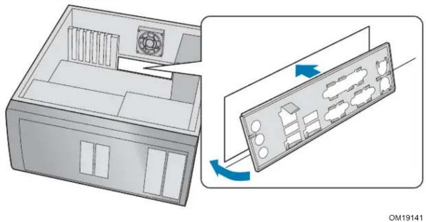
The desktop board comes with an I/O shield. When installed in the chassis, the shield blocks radio frequency transmissions, protects internal components from dust and foreign objects, and promotes correct airflow within the chassis.
Install the I/O shield before installing the desktop board in the chassis. Place the shield inside the chassis as shown in Figure 4. Press the shield into place so that it fits tightly and securely. If the shield doesn't fit, obtain a properly-sized shield from the chassis supplier.
natural_image
Diagram showing a computer case with ventilation slots and a device casing, illustrating internal components and airflow direction (no text or symbols)Figure 4. Installing the I/O Shield
Installing and Removing the Desktop Board

CAUTION
Only qualified technical personnel should do this procedure. Disconnect the computer from its power source before performing the procedures described here. Failure to disconnect the power before you open the computer can result in personal injury or equipment damage.
Refer to your chassis manual for instructions on installing and removing the desktop board.
Figure 5 shows the location of the mounting screw holes for desktop board D102GGC2.

natural_image
Green printed circuit board with various electronic components and connectors (no readable text or symbols)Figure 5. Desktop Board D102GGC2 Mounting Screw Hole Locations
Installing and Removing a Processor
Instructions on how to install a processor to the desktop board are given below.
Installing a Processor

CAUTION
Before installing or removing a processor, make sure the AC power has been removed by unplugging the power cord from the computer; the standby power LED should not be lit (see Figure 3 on page 20). Failure to do so could damage the processor and the board.
To install a processor, follow these instructions:
- Observe the precautions in "Before You Begin" on page 23.
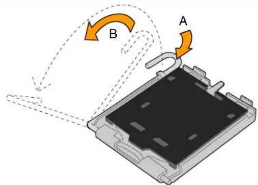
- Open the socket lever by pushing the lever down and away from the socket (Figure 6, A and B).
text_image
Diagram showing a device with labeled components A and B, indicating directional flow or movement around a component.OM17210
Figure 6. Lift Socket Lever
- Lift the load plate (Figure 7, C). Do not touch the socket contacts (Figure 7, D).

text_image
C D DOM17211
Figure 7. Lift the Load Plate and Don't Touch the Socket Contacts
- Remove the plastic protective socket cover from the load plate (Figure 8, E). Do not discard the protective socket cover. Always replace the socket cover if the processor is removed from the socket.

natural_image
3D diagram of an open computer chip with a highlighted internal component and an arrow indicating direction (no text or symbols)OM17228
Figure 8. Remove the Protective Socket Cover
- Remove the processor from the protective processor cover. Hold the processor only at the edges, being careful not to touch the bottom of the processor (see Figure 9). Do not discard the protective processor cover. Always replace the processor back to the package if the processor is removed from the socket.

natural_image
Illustration showing a green CPU socket being compressed and then placed on a green circuit board with a red prohibition symbol (no text or symbols present)OM17213
Figure 9. Remove the Processor from the Protective Processor Cover/Do Not Touch
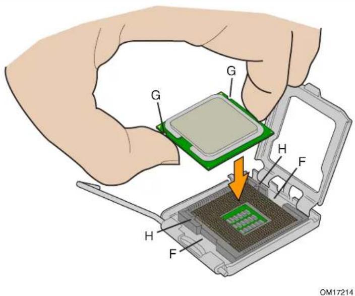
- Hold the processor with your thumb and index fingers oriented as shown in Figure 10. Make sure fingers align to the socket cutouts (Figure 10, F). Align notches (Figure 10, G) with the socket (Figure 10, H). Lower the processor straight down without tilting or sliding the processor in the socket.
text_image
G G H F H F OM17214Figure 10. Install Processor
- While pressing down on the load plate (Figure 11, I), close and engage the socket lever (Figure 11, J).

text_image
J I OM17215Figure 11. Close the Load Plate
Installing the Processor Fan Heat Sink
Desktop board D102GGC2 has an integrated processor fan heat sink retention mechanism (RM). For instructions on how to attach the processor fan heat sink to the integrated processor fan heat sink RM, refer to the boxed processor manual or the Intel World Wide Web site at:
The Boxed Intel® Pentium® 4 Processor in the 775-Land Package
Connecting the Processor Fan Heat Sink Cable
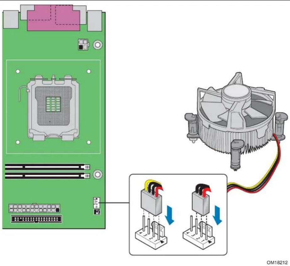
Connect the processor fan heat sink cable to the 4-pin processor fan connector (see Figure 12).
text_image
OM18212Figure 12. Connecting the Processor Fan Heat Sink Cable to the Processor Fan Connector
Removing the Processor
For instruction on how to remove the processor fan heat sink and processor, refer to the processor installation manual or the Intel World Wide Web site at:
The Boxed Intel® Pentium® 4 Processor in the 775-Land Package
Installing and Removing Memory

NOTE
To be fully compliant with all applicable Intel SDRAM memory specifications, the boards require DIMMs that support the Serial Presence Detect (SPD) data structure. You can access the PC Serial Presence Detect Specification at: http://www.intel.com/technology/memory/ddr/specs/dda18c32_64_128x72ag_a.pdf
The desktop board has two 240-pin DIMM sockets arranged as DIMM 0 and DIMM 1.
Installing DIMMs

NOTE
Install memory in the DIMM sockets prior to installing a PCI Express x16 card to avoid interference with the memory retention mechanism.
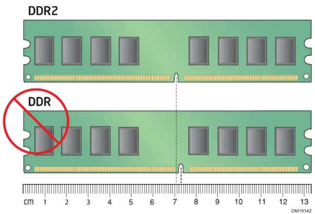
To make sure you have the correct DIMM, place it on the illustration in Figure 13 showing the DDR2 DIMM. All the notches should match the DDR2 DIMM.
text_image
DDR2 DDR cm 1 2 3 4 5 6 7 8 9 10 11 12 13 OM19142Figure 13. Use DDR DIMMs
- Observe the precautions in "Before You Begin" on page 23.
- Turn off all peripheral devices connected to the computer. Turn off the computer and disconnect the AC power cord.
- Remove the computer's cover and locate the DIMM sockets (see Figure 14).
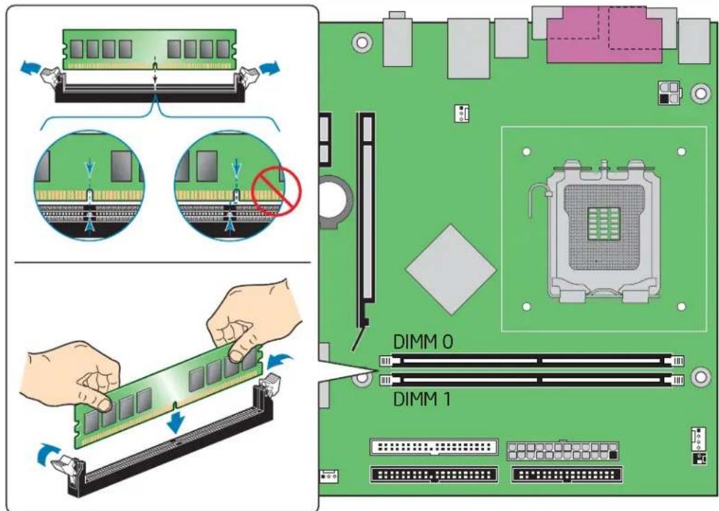
text_image
Diagram illustrating the assembly of a computer RAM module with labeled DIMM 0 and DIMM 1 components.OM19144
Figure 14. Installing a DIMM
- Remove the PCI Express video card if it interferes with the DIMM retaining clips from being easily opened and closed.
- Make sure the clips at either end of the DIMM socket(s) are pushed outward to the open position.
- Holding the DIMM by the edges, remove it from its anti-static package.
- Position the DIMM above the socket. Align the small notch at the bottom edge of the DIMM with the key in the socket (see Figure 14).
- Insert the bottom edge of the DIMM into the socket.
- When the DIMM is inserted, push down on the top edge of the DIMM until the retaining clips snap into place. Make sure the clips are firmly in place.
- Reinstall the PCI Express card if it was removed prior to installing the DIMMs.
- Replace the computer's cover and reconnect the AC power cord.
Removing DIMMs
To remove a DIMM, follow these steps:
- Observe the precautions in "Before You Begin" on page 23.
- Turn off all peripheral devices connected to the computer. Turn off the computer.
- Remove the AC power cord from the computer.
- Remove the computer's cover.
- Remove the PCI Express card if it interferes with the DIMM clips from being easily opened and closed.
- Gently spread the retaining clips at each end of the DIMM socket. The DIMM pops out of the socket.
- Hold the DIMM by the edges, lift it away from the socket, and store it in an anti-static package.
- Reinstall the PCI Express card if you removed it before taking out the DIMM.
- Reinstall and reconnect any parts you removed or disconnected to reach the DIMM sockets.
- Replace the computer's cover and reconnect the AC power cord.
Installing and Removing a PCI Express x16 Card

CAUTION
When installing a PCI Express x16 card on the desktop board, ensure that the card is fully seated in the PCI Express x16 connector before you power on the system. If the card is not fully seated in the PCI Express connector, an electrical short may result across the PCI Express connector pins. Depending on the over-current protection of the power supply, certain board components and/or traces may be damaged.
Installing a PCI Express x16 Card
- Observe the precautions in "Before You Begin" on page 23.
- Place the card in the PCI Express x16 connector and press down on the card until it is completely seated in the connector (Figure 15, A) and the card retention notch snaps into place around the RM pin.
- Secure the card's metal bracket to the chassis back panel with a screw (Figure 15, B).
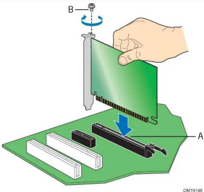
text_image
B A OM19146Figure 15. Installing a PCI Express x16 Card
Removing the PCI Express x16 Card
Follow these instructions to remove the PCI Express x16 card from the RM:
- Observe the precautions in "Before You Begin" on page 23.
- Remove the screw ( Figure 16, A) that secures the card's metal bracket to the chassis back panel.
- Push back on the RM lever (Figure 16, B) until the retention pin completely clears the notch in the card.
- Pull the card straight up.

text_image
A BOM19145
Figure 16. Removing a PCI Express x16 Card
Connecting the IDE Cable
The IDE cable can connect two drives to the desktop board. The cable supports the ATA-100 transfer protocol. Figure 17 shows the correct installation of the cable.

NOTES
ATA-100 compatible cables are backward compatible with drives using slower IDE transfer protocols. If an ATA-100 disk drive and a disk drive using any other IDE transfer protocol are attached to the same cable, the maximum transfer rate between the drives may be reduced to that of the slowest drive.
Do not connect an ATA device as a slave on the same IDE cable as an ATAPI master device. For example, do not connect an ATA hard drive as a slave to an ATAPI CD-ROM drive.
For correct function of the cable:
- Observe the precautions in "Before You Begin" on page 23.
- Attach the cable end with the single connector (blue) to the Intel desktop board (Figure 17).
- Attach the cable end with the two closely spaced connectors (gray and black) to the drives.
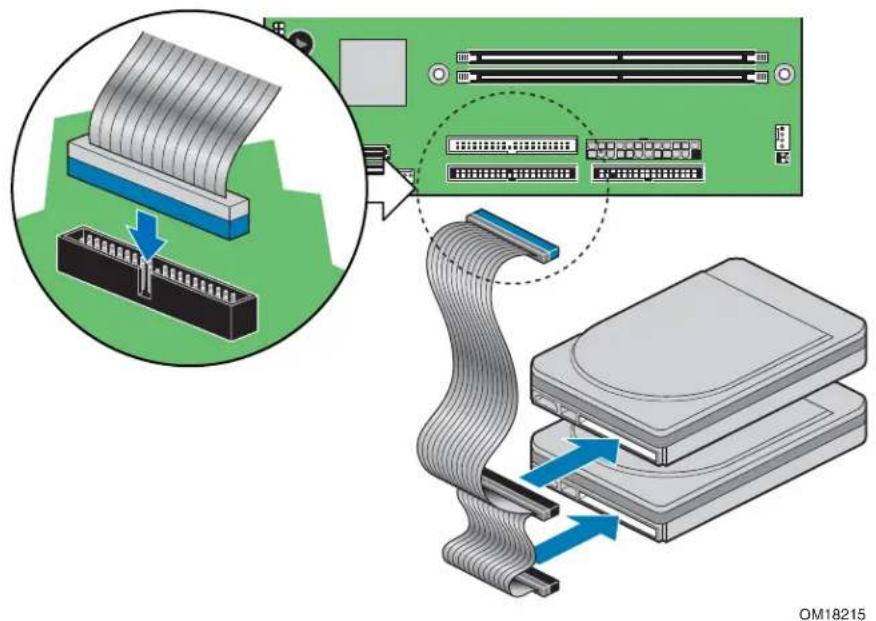
text_image
Diagram illustrating the installation of a hard disk drive into a computer motherboard, showing cable routing and component assembly.Figure 17. Connecting the IDE Cable
Connecting the Serial ATA (SATA) Cable
The SATA cable (4-conductor) supports the Serial ATA protocol and connects a single drive to the desktop board.
For correct cable function:
- Observe the precaution in "Before You Begin" on page 23.
- Attach the locking cable end to the connector (Figure 18, A) on the board.
- Attach the cable end without a lock to the drive (Figure 18, B).
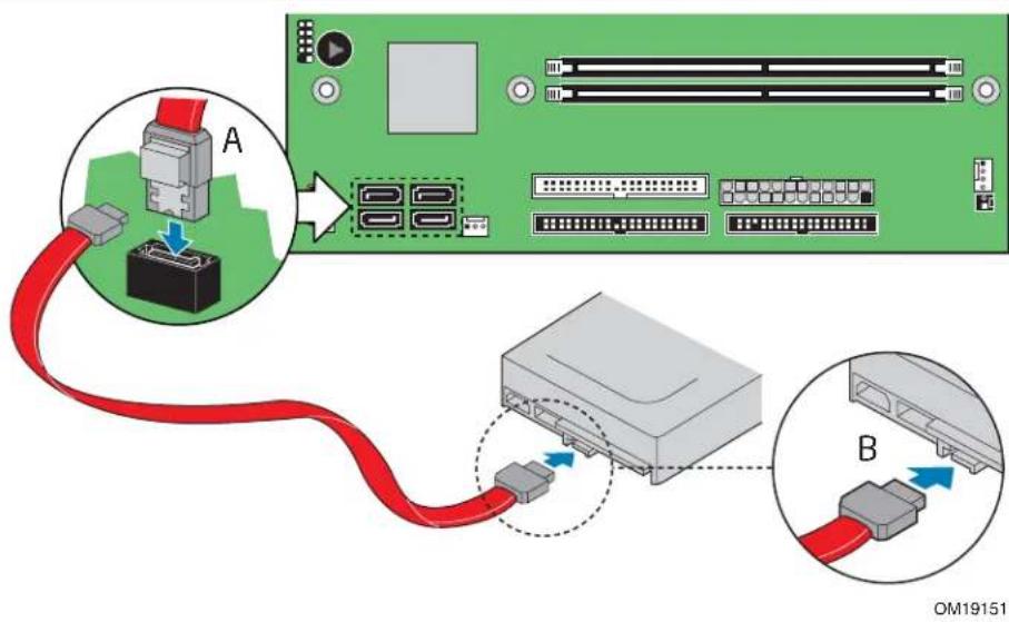
text_image
A B OM19151Figure 18. Connecting the Serial ATA Cable
Connecting Internal Headers
Before connecting cables to the internal headers, observe the precautions in "Before You Begin" on page 23. Figure 19 shows the location of the internal headers.
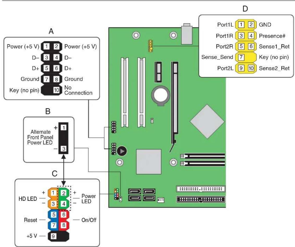
text_image
A Power (+5 V) 1 2 Power (+5 V) D- 3 4 D- D+ 5 6 D+ Ground 7 8 Ground Key (no pin) 10 No Connection B Alternate Front Panel Power LED + 1 3 C HD LED + 1 2 + Power LED Reset - 3 4 On/Off +5 V - 9 D Port1L 1 2 GND Port1R 3 4 Presence# Port2R 5 6 Sense1_Ret Sense_Send 7 Key (no pin) Port2L 9 10 Sense2_RetOM19152
Item Description
A Hi-speed USB 2.0 (two)
B Alternate front panel power LED
C Front panel
D Front panel audio
Figure 19. Internal Headers
Installing a Front Panel Audio Solution
Figure 19, D on page 38 shows the location of the yellow front panel audio header. Table 5 shows the pin assignments for the front panel audio header.
Table 5. Front Panel Audio Header Signal Names for High Definition Audio
| Pin | Signal | Name | Pin | Signal | Name |
| 1 PORT | 1L 2 GND | ||||
| 3 | PORT | 1R | 4 | PRESENCE# | |
| 5 | PORT | 2R | 6 | SENSE1_RETURN | |
| 7 | SENSE_SEND | 8 | KEY | (no pin) | |
| 9 | PORT | 2L | 10 | SENSE2_RETURN |
To install the cable that connects the front panel audio solution to the front panel audio header, follow these steps:
- Observe the precautions in "Before You Begin" on page 23.
- Turn off all peripheral devices connected to the computer. Turn off the computer and disconnect the AC power cord.
- Remove the cover.
- Install a correctly keyed and shielded front panel audio cable.
NOTE: some chassis still use a front panel audio solution based on the AC '97 audio specification. Refer to Table 6 to connect an AC '97 front panel solution to the front panel audio header on the board. The front panel audio jacks will need to be manually configured for microphone or line out functionality in your audio software.
Table 6. AC '97 Audio Header Signal Names
| Pin | Signal | Name | Pin | Signal | Name |
| 1 MIC | 2 AUD_GND | ||||
| 3 | MIC_BIAS | 4 | AUD_GND | ||
| 5 | FP_OUT_R | 6 | FP_RETURN_R | ||
| 7 | AUD_5V | 8 | KEY | ||
| 9 | FP_OUT_L | 10 | FP_RETURN_L |
- Connect the audio cable to the front panel audio solution.
- Replace the cover.
To restore back panel audio, follow these steps:
- Observe the precautions in "Before You Begin" on page 23.
- Turn off all peripheral devices connected to the computer. Turn off the computer and disconnect the AC power cord.
- Remove the cover.
- Remove the front panel audio cable.
- Replace the cover.
Connecting Hi-Speed USB 2.0 Headers
Before connecting the USB 2.0 headers, observe the precautions in "Before You Begin" on page 23. See Figure 19, A on page 38 for the location of the black USB 2.0 headers.
Table 7 shows the pin assignments for the headers.
Table 7. Hi-Speed USB 2.0 Header Signal Names
| USB Port A USB Port B | |||||
| Pin Signal Name Pin Signal Name | |||||
| 1 | Power | 2 | Power | ||
| 3 | D- | 4 | D- | ||
| 5 | D+ | 6 | D+ | ||
| 7 | Ground | 8 | Ground | ||
| 9 | Key | 10 | No connect | ||
Note: USB ports may be assigned as needed.
Connecting the Front Panel Header
Before connecting the front panel header, observe the precautions in "Before You Begin" on page 23. See Figure 19, C on page 38 for the location of the multi-colored front panel header.
Table 8 shows the pin assignments for the front panel header.
Table 8. Front Panel Header Signal Names
| Pin | Signal | In/Out | Description | Pin | Signal | In/Out | Description |
| Hard Drive Activity LED | Power LED | ||||||
| 1 | HD_PWR | Out | Hard disk LED pull-up (330 Ω) to +5 V | 2 | HDR_BLNK_GRN | Out | Front panel green LED |
| 3 | HDA# | Out | Hard disk active LED | 4 | HDR_BLNK_YEL | Out | Front panel yellow LED |
| Reset Switch | On/Off Switch | ||||||
| 5 | Ground | Ground | 6 | SWITCH_ON# | In | Power switch | |
| 7 | FP_RESET# | In | Reset switch | 8 | Ground | Ground | |
| Power | Not Connected | ||||||
| 9 | +5 V | Power | 10 | N/C | No pin | ||
Setting Up the Flexible 6-Channel Audio with Jack Re-tasking (Optional)
After installing the Realtek audio driver, the multi-channel audio feature can be enabled. Figure 20 shows the board's back panel audio connectors.

text_image
A B C OM18218Item Description
A Rear left/right out or Line In
B Front left/right out or Line Out
C Center/LFE (Subwoofer) or Mic In
Figure 20. Back Panel Audio Connectors for a Flexible 6-Channel Audio System
Multi-Channel Analog Audio
Connect two speakers to the front left/right out (Figure 20, B) and two speakers to the rear left/right out (Figure 20, A) for both 4- and 6-channel audio configurations. For 6-channel audio, connect two additional speakers to the center LFE out (Figure 20, C).
Connecting Chassis Fan Cables
Figure 21 shows the location of the chassis fan headers. Connect the chassis fan cables to these headers.
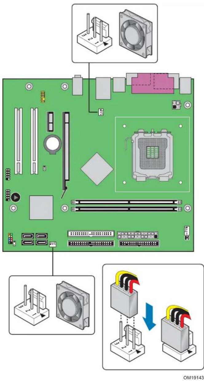
text_image
Diagram of a computer motherboard with labeled components and wiring connections, including fan, CPU socket, and power connector.Figure 21. Location of the Chassis Fan Headers
Connecting Power Cables

CAUTION
Failure to use the appropriate power supply and/or not connecting the 12 V (2 x 2) power connector to the desktop board may result in damage to the board or the system may not function properly.
See Table 3 on page 13 for power supply requirements. Figure 22 shows the location of the power connectors.
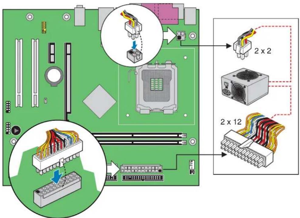
text_image
Diagram illustrating computer motherboard components with labeled connectors and wiring connections for 2x2 and 2x12 processorsOM19156
Figure 22. Connecting 2 x 12 Power Supply Cables
- Observe the precautions in "Before You Begin" on page 23.
- Connect the 12 V processor core voltage power supply cable to the 2 x 2 connector.
- Connect the main power supply cable to the 2 x 12 connector.
Other Connectors
Figure 23 shows the location of the PCI bus add-in card, PCI Express x1, chassis intrusion, and diskette drive connectors.
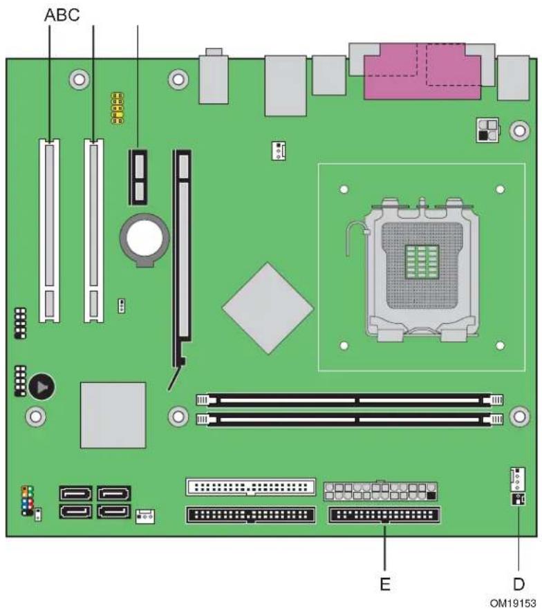
text_image
ABC E D OM19153| Item | Description | ||
| A | PCI bus add-in card connector 2 | ||
| B | PCI bus add-in card connector 1 | ||
| C | PCI Express x1 connector | ||
| D | Chassis intrusion connector | ||
| E | Diskette | drive | connector |
Figure 23. Location of Other Connectors on Desktop Board D102GGC2
Setting the BIOS Configuration Jumper

NOTE
Always turn off the power and unplug the power cord from the computer before changing the jumper. Moving the jumper with the power on may result in unreliable computer operation.
Figure 24 shows the location of the desktop board's BIOS configuration jumper block.
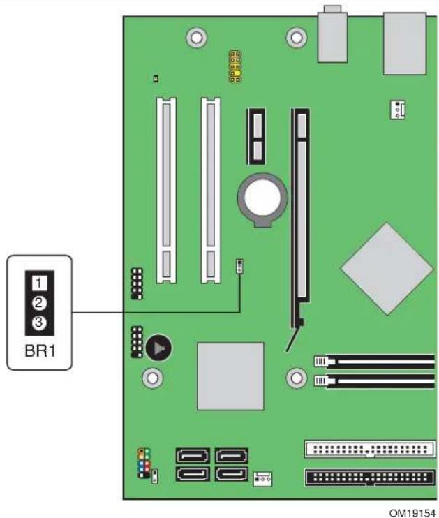
text_image
BR1 OM19154Figure 24. Location of the BIOS Configuration Jumper Block
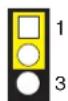
The three-pin BIOS jumper block enables all board configuration to be done in the BIOS Setup program. Table 9 shows the jumper settings for the Setup program modes.
Table 9. Jumper Settings for the BIOS Setup Program Modes
| Jumper Setting Mode Description | ||
 | Normal (default) (1-2) The BIOS uses the current configuration and passwords for booting. | |
 | Configure (2-3) After the Power-On Self-Test (POST) runs, the BIOS displays the Maintenance Menu. Use this menu to clear passwords. | |
 | Recovery (None) The BIOS recovers data from a recovery diskette in the event of a failed BIOS update. | |
Clearing Passwords
This procedure assumes that the board is installed in the computer and the configuration jumper is set to normal mode.
- Observe the precautions in "Before You Begin" on page 23.
- Turn off all peripheral devices connected to the computer. Turn off the computer. Disconnect the computer's power cord from the AC power source (wall outlet or power adapter).
- Remove the computer cover.
- Find the configuration jumper block (see Figure 24).
- Place the jumper on pins 2-3 as shown below.

- Replace the cover, plug in the computer, turn on the computer, and allow it to boot.
- The computer starts the Setup program. Setup displays the Maintenance menu.
- Use the arrow keys to select Clear Passwords. Press
and Setup displays a pop-up screen requesting that you confirm clearing the password. Select Yes and press . Setup displays the maintenance menu again. - Press
to save the current values and exit Setup. - Turn off the computer. Disconnect the computer's power cord from the AC power source.
- Remove the computer cover.
- To restore normal operation, place the jumper on pins 1-2 as shown below.
- Replace the cover, plug in the computer, and turn on the computer.
Replacing the Battery
A coin-cell battery (CR2032) powers the real-time clock and CMOS memory. When the computer is not plugged into a wall socket, the battery has an estimated life of three years. When the computer is plugged in, the standby current from the power supply extends the life of the battery. The clock is accurate to ± 13 minutes/year at 25 °C with 3.3 VSB applied.
When the voltage drops below a certain level, the BIOS Setup program settings stored in CMOS RAM (for example, the date and time) might not be accurate. Replace the battery with an equivalent one. Figure 25 on page 51 shows the location of the battery.

CAUTION
Risk of explosion if the battery is replaced with an incorrect type. Batteries should be recycled where possible. Disposal of used batteries must be in accordance with local environmental regulations.

PRECAUTION
To replace the battery, follow these steps:
- Observe the precautions in "Before You Begin" (see page 23).
- Turn off all peripheral devices connected to the computer. Disconnect the computer's power cord from the AC power source (wall outlet or power adapter).
- Remove the computer cover.
- Locate the battery on the board (see Figure 25).
- With a medium flat-bladed screwdriver, gently pry the battery free from its connector. Note the orientation of the “+” and “-” on the battery.
- Install the new battery in the connector, orienting the "+" and "-" correctly.
- Replace the computer cover.

text_image
Diagram illustrating the assembly of a computer motherboard with labeled components and a magnified view showing component insertion.Figure 25. Removing the Battery
3 Updating the BIOS
The BIOS Setup program can be used to view and change the BIOS settings for the computer. You can access the BIOS Setup program by pressing the
This chapter tells you how to update the BIOS by either using the Intel Express BIOS Update utility or the Iflash Memory Update utility, and how to recover the BIOS if an update fails.
Updating the BIOS with the Intel® Express BIOS Update Utility
With the Intel Express BIOS Update utility you can update the system BIOS while in the Windows environment. The BIOS file is included in an automated update utility that combines the functionality of the Intel® Flash Memory Update Utility and the ease-of-use of Windows-based installation wizards.
To update the BIOS with the Intel Express BIOS Update utility:
- Go to the Intel World Wide Web site:
http://support.intel.com/support/motherboards/desktop/ - Navigate to the D102GGC2 page, click “[view] Latest BIOS updates,” and select the Express BIOS Update utility file.
- Download the file to your hard drive. (You can also save this file to a diskette. This is useful if you are updating the BIOS for multiple identical systems.)
- Close all other applications. This step is required. Your system will be rebooted at the last Express BIOS Update window.
- Double-click the executable file from the location on your hard drive where it was saved. This runs the update program.
- Follow the instructions provided in the dialog boxes to complete the BIOS update.
Updating the BIOS with the Iflash Memory Update Utility
With the Iflash BIOS update utility you can update the system BIOS from a floppy disk in a USB floppy disk drive or other bootable media. The utility available on the Intel World Wide Web site provides a simple method for creating a bootable flash memory update floppy that will automatically update your BIOS.
Obtaining the BIOS Update File
You can update to a new version of the BIOS by using the BIOS update file. The BIOS update file is a compressed self-extracting archive that contains all the files you need to update the BIOS. The BIOS update file contains:
- New BIOS files
- BIOS recovery files
• Intel Flash Memory Update Utility
You can obtain the BIOS update file through your computer supplier or by navigating to the Desktop Board D102GGC2 page on the Intel World Wide Web site at:
http://support.intel.com/support/motherboards/desktop
Navigate to the D102GGC2 page, click “[view] Latest BIOS updates,” and select the Iflash BIOS Update utility file.

NOTE
Review the instructions distributed with the update utility before attempting a BIOS update.
The Iflash Memory Update utility allows you to:
- Update the BIOS in flash memory
- Update the language section of the BIOS
Updating the BIOS

CAUTION
The AUTOEXEC.BAT file provided with the update files updates the BIOS. Do not interrupt the process or the system may not function.
- Boot the computer with the BIOS update diskette in drive A. During system boot, the AUTOEXEC.BAT file provided with the update files will automatically run the BIOS update process.
- When the update process is complete, the monitor will display a message telling you to remove the diskette and to reboot the system.
- As the computer boots, check the BIOS identifier (version number) to make sure the update was successful. If a logo appears, press
to view the POST messages.
Recovering the BIOS
It is unlikely that anything will interrupt the BIOS update; however, if an interruption occurs, the BIOS could be damaged. For information about recovering the BIOS for desktop board D102GGC2, go to:
http://support.intel.com/support/motherboards/desktop/
A Error Messages and Indicators
Desktop Board D102GGC2 reports POST errors in two ways:
- By sounding a beep code
- By displaying an error message on the monitor
BIOS Beep Codes
The BIOS also issues a beep code (one long tone followed by two short tones) during POST if the video configuration fails (a faulty video card or no card installed) or if an external ROM module does not properly checksum to zero. Table 10 lists the BIOS codes.
Table 10. Beep Codes
| Beep | Description | |
| 3 | No | memory |
| Siren CPU overheat (on reboot) | ||
BIOS Error Messages
When a recoverable error occurs during the POST, the BIOS displays an error message describing the problem. Table 11 gives an explanation of the BIOS error messages.
Table 11. BIOS Error Messages
| Error Message Explanation | |
| PROCESSOR_THERMAL_TRIP_ERROR | CPU was previously shutdown due to a thermal event (overheating). |
| MULTI_BIT_ECC_ERROR The firmware has detected that a Multi-Bit ECC Error occurred. | |
| SINGLE_BIT_ECC_ERROR The firmware has detected that a Single-Bit ECC Error occurred. | |
| CMOS_BATTERY_ERROR The firmware has detected that a CMOS battery failure occurred. | |
| CMOS_CHECKSUM_ERROR The firmware has detected that a CMOS Checksum Error occurred. | |
| CMOS_TIMER_ERROR The firmware has detected that the system date/time has not been set. | |
| MEMORY_SIZE_DECREASE_ERROR The firmware has detected that the system memory has decreased. | |
| INTRUDER_DETECTION_ERROR | The system chassis was opened. |
| SPD_TOLER_ERROR | SERIAL PRESENCE DETECT (SPD) device data missing or inconclusive. Properly programmed SPD device data is required for reliable operation. DDR2 533 MHz memory assumed at slowest timings. |
| MEM_OPTIMAL_ERROR | The installed amount of memory in Channel A is not equal to the amount of memory in Channel B. Maximum memory performance is achieved with equal amounts of memory installed in each channel. |
B Regulatory Compliance
This appendix contains the following regulatory compliance information for Desktop Board D102GGC2:
- Safety regulations
• European Union Declaration of Conformity statement
• Product Ecology statements
• Electromagnetic Compatibility (EMC) regulations
• Product certifications
Safety Regulations
Desktop Board D102GGC2 complies with the safety regulations stated in Table 12 when correctly installed in a compatible host system.
Table 12. Safety Regulations
| Regulation | Title |
| UL 60950-1:2003/CSA C22.2 No. 60950-1-03 | Information Technology Equipment – Safety - Part 1: General Requirements (USA and Canada) |
| EN 60950-1:2002 Information Technology Equipment – Safety - Part 1: General Requirements (European Union) | |
| IEC 60950-1:2001, First Edition Information Technology Equipment – Safety - Part 1: General Requirements (International) | |
Place Battery Marking
There is insufficient space on this desktop board to provide instructions for replacing and disposing of the Lithium ion coin cell battery. For system safety certification, the statement below or an equivalent statement is required to be permanently and legibly marked on the chassis near the battery.

CAUTION
Risk of explosion if the battery is replaced with an incorrect type. Batteries should be recycled where possible. Disposal of used batteries must be in accordance with local environmental regulations.
Related Links
For information about replacing the battery, go to page 47.
European Union Declaration of Conformity Statement
We, Intel Corporation, declare under our sole responsibility that the product Intel ^® Desktop Board D102GGC2 is in conformity with all applicable essential requirements necessary for CE marking, following the provisions of the European Council Directive 89/336/EEC (EMC Directive) and Council Directive 73/23/EEC (Safety/Low Voltage Directive).
The product is properly CE marked demonstrating this conformity and is for distribution within all member states of the EU with no restrictions.
CE
This product follows the provisions of the European Directives 89/336/EEC and 73/23/EEC.
Čeština Tento výrobek odpovídá požadavkům evropských směrnic 89/336/EEC a 73/23/EEC.
Dansk Dette produkt er i overensstemmelse med det europæiske direktiv 89/336/EEC & 73/23/EEC.
Dutch Dit product is in navolging van de bepalingen van Europees Directief 89/336/EEC & 73/23/EEC.
Eesti Antud toode vastab Euroopa direktiivides 89/336/EEC ja 73/23/EEC kehtestatud nõuetele.
Suomi Tämä tuote noudattaa EU-direktiivin 89/336/EEC & 73/23/EEC määräyksiä.
Français Ce produit est conforme aux exigences de la Directive Européenne 89/336/EEC & 73/23/EEC.
Deutsch Dieses Produkt entspricht den Bestimmungen der Europäischen Richtlinie 89/336/EEC & 73/23/EEC.
Ελληνικά Το παρόν προϊόν ακολουθεί τις διατάξεις των Ευρωπαϊκών Οδηγιών 89/336/ΕΟΚ και 73/23/ΕΟΚ.
Magyar E termék megfelel a 89/336/EEC és 73/23/EEC Európai Irányelv előírásainak.
Icelandic Pessi vara stenst reglugerð Evrópska Efnahags Bandalagsins númer 89/336/ EEC & 73/23/EEC.
Italiano Questo prodotto è conforme alla Direttiva Europea 89/336/EEC & 73/23/EEC.
Latviešu Šis produkts atbilst Eiropas Direktīvu 89/336/EEC un 73/23/EEC noteikumiem.
Lietuvių Šis produktas atitinka Europos direktyvų 89/336/EEC ir 73/23/EEC nuostatas.
Malti Dan il-prodott hu konformi mal-provvedimenti tad-Direttivi Ewropej 89/336/EEC u 73/23/EEC.
Norsk Dette produktet er i henhold til bestemmelsene i det europeiske direktivet 89/336/ EEC & 73/23/EEC.
Polski Niniejszy produkt jest zgodny z postanowieniami Dyrektyw Unii Europejskiej 89/336/EWG i 73/23/EWG.
Portuguese Este produto cumpre com as normas da Diretiva Européia 89/336/EEC & 73/23/EEC.
Español Este producto cumple con las normas del Directivo Europeo 89/336/EEC & 73/23/EEC.
Product Ecology Statements
The following information is provided to address worldwide product ecology concerns and regulations.
Recycling Considerations
As part of its commitment to environmental responsibility, Intel has implemented the Intel Product Recycling Program to allow retail consumers of Intel's branded products to return used products to select locations for proper recycling.
Please consult the http://www.intel.com/intel/other/chs/product_ecology/Recycling_Program.htm for the details of this program, including the scope of covered products, available locations, shipping instructions, terms and conditions, etc.
中文
请参考http://www.intel.com/intel/other/ehs/product_ecology/Recycling_Program.htm
http://www.intel.com/intel/other/chs/product_ecology/Recycling_Program.htm
Lead-Free Desktop Board
This desktop board is lead free although certain discrete components used on the board contain a small amount of lead which is necessary for component performance and/or reliability. This desktop board is referred to as “Lead-free second level interconnect.” The board substrate and the solder connections from the board to the components (second-level connections) are all lead free. Table 13 shows the various forms of the “Lead-Free 2 ^nd Level Interconnect” mark as it appears on the board and accompanying collateral.
Table 13. Lead-Free Board Markings
| Description | Mark | |
| Lead-Free 2ndLevelInterconnect: This symbol is used to identify electrical and electronic assemblies and components in which the lead (Pb) concentration level in the desktop board substrate and the solder connections from the board to the components (second-level interconnect) is not greater than 0.1% by weight (1000 ppm). |  | 2ndLevel Interconnect |
| or | ||
 | 2ndIvl Intct | |
| or | ||
 | 2LI | |
2^nd Level Interconnect
EMC Regulations
Desktop Board D102GGC2 complies with the EMC regulations stated in Table 14 when correctly installed in a compatible host system.
Table 14. EMC Regulations
| Regulation | Title |
| FCC Class B Title 47 of the Code of Federal Regulations, Parts 2 and 15, Subpart B, Radio Frequency Devices. (USA) | |
| ICES-003 (Class B) Interference-Causing Equipment Standard, Digital Apparatus. (Canada) | |
| EN55022: 1998 (Class B) | Limits and methods of measurement of Radio Interference Characteristics of Information Technology Equipment. (European Union) |
| EN55024: 1998 Information | Technology Equipment – Immunity Characteristics Limits and methods of measurement. (European Union) |
| AS/NZS CISPR22 (Class B) | Australian Communications Authority, Standard for Electromagnetic Compatibility. (Australia and New Zealand) |
| CISPR 22, 3^rd Edition, (Class B) | Limits and methods of measurement of Radio Disturbance Characteristics of Information Technology Equipment. (International) |
| CISPR 24: 1997 Information | Technology Equipment – Immunity Characteristics – Limits and Methods of Measurement. (International) |
| VCCI (Class B) Voluntary Control for Interference by Information Technology Equipment (Japan) | |
Japanese Kanji statement translation: This is a Class B product based on the standard of the Voluntary Control Council for Interference from Information Technology Equipment (VCCI). If this is used near a radio or television receiver in a domestic environment, it may cause radio interference. Install and use the equipment according to the instruction manual.
Korean Class B statement translation: This is household equipment that is certified to comply with EMC requirements. You may use this equipment in residential environments and other non-residential environments.
Ensure Electromagnetic Compatibility (EMC) Compliance
Before computer integration, make sure that the power supply and other modules or peripherals, as applicable, have passed Class B EMC testing and are marked accordingly.
Pay close attention to the following when reading the installation instructions for the host chassis, power supply, and other modules:
• Product certifications or lack of certifications
• External I/O cable shielding and filtering
- Mounting, grounding, and bonding requirements
• Keying connectors when mating the wrong connectors could be hazardous
If the power supply and other modules or peripherals, as applicable, are not Class B EMC compliant before integration, then EMC testing may be required on a representative sample of the newly completed computer.
Product Certifications
Board-Level Certification Markings
Desktop Board D102GGC2 has the following product certification markings:
Table 15. Product Certification Markings
| Description | Mark | |
| UL joint US/Canada Recognized Component mark. Includes adjacent UL file number for Intel desktop boards: E210882. |  | |
| FCC Declaration of Conformity logo mark for Class B equipment. Includes Intel name and DD102GGC2 model designation. |  | Trade NameModel Number |
| CE mark. Declaring compliance to European Union (EU) EMC directive (89/336/EEC) and Low Voltage directive (73/23/EEC). |  | |
| Australian Communications Authority (ACA) C-tick mark. Includes adjacent Intel supplier code number, N-232. |  | |
| Japan VCCI (Voluntary Control Council for Interference) mark. |  | |
| S. Korea MIC (Ministry of Information and Communication) mark. Includes adjacent MIC certification number: CPU-D102GGC2.For information about MIC certification, go tohttp://support.intel.com/support/motherboards/desktop/ |  | |
| Taiwan BSMI (Bureau of Standards, Metrology and Inspections) mark.Includes adjacent Intel company number, D33025. |  | |
| Printed wiring board manufacturer's recognition mark. Consists of a unique UL recognized manufacturer's logo, along with a flammability rating (solder side). | V-0 | |
Chassis and Component Certifications
Ensure that the chassis and certain components; such as the power supply, peripheral drives, wiring, and cables; are components certified for the country or market where used. Agency certification marks on the product are proof of certification. Typical product certifications include:
In Europe
The CE marking signifies compliance with all applicable European requirements. If the chassis and other components are not properly CE marked, a supplier's Declaration of Conformity statement to the European EMC directive and Low Voltage directive (as applicable), should be obtained. Additionally, other directives, such as the Radio and Telecommunications Terminal Equipment (R&TTE) directive may also apply depending on product features.
In the United States
A certification mark by a Nationally Recognized Testing Laboratory (NRTL) such as UL, CSA, or ETL signifies compliance with safety requirements. Wiring and cables must also be UL listed or recognized and suitable for the intended use. The FCC Class B logo for home or office use signifies compliance with electromagnetic interference (EMI) requirements.
In Canada
A nationally recognized certification mark such as CSA or cUL signifies compliance with safety requirements. The Industry Canada statement at the front of this product guide demonstrates compliance with Canadian EMC regulations.