D525MW - Motherboard INTEL - Free user manual and instructions
Find the device manual for free D525MW INTEL in PDF.

User questions about D525MW INTEL
0 question about this device. Answer the ones you know or ask your own.
Ask a new question about this device
Download the instructions for your Motherboard in PDF format for free! Find your manual D525MW - INTEL and take your electronic device back in hand. On this page are published all the documents necessary for the use of your device. D525MW by INTEL.
USER MANUAL D525MW INTEL
Intel® Desktop Board D525MW Product Guide
Order Number: E95576-001
Revision History
| Revision | Revision History | Date | |
| -001 First | release of the Intel Guide | ® Desktop Board D525MW Product | June 2010 |
Disclaimer
Information in this document is provided in connection with Intel ^® products. No license, express or implied, by estoppel or otherwise, to any intellectual property rights is granted by this document. Except as provided in Intel's Terms and Conditions of Sale for such products, Intel assumes no liability whatsoever, and Intel disclaims any express or implied warranty, relating to sale and/or use of Intel products including liability or warranties relating to fitness for a particular purpose, merchantability, or infringement of any patent, copyright or other intellectual property right. Intel products are not intended for use in medical, life saving, or life sustaining applications. Intel may make changes to specifications and product descriptions at any time, without notice.
Intel Desktop Board D525MW may contain design defects or errors known as errata which may cause the product to deviate from published specifications. Current characterized errata are available on request.
Contact your local Intel sales office or your distributor to obtain the latest specifications and before placing your product order.
Copies of documents which have an ordering number and are referenced in this document, or other Intel literature, may be obtained from Intel Corporation by going to the World Wide Web site at: http://www.intel.com/ or by calling 1-800-548-4725.
Intel, the Intel logo, and Intel Atom are trademarks of Intel Corporation in the U. S. and other countries.
* Other names and brands may be claimed as the property of others.
Copyright © 2010 Intel Corporation. All rights reserved.
This Product Guide gives information about board layout, component installation, and regulatory requirements for Intel ^® Desktop Board D525MW.
Intended Audience
The Product Guide is intended for technically qualified personnel. It is not intended for general audiences.
Intended Uses
All Intel ^® Desktop Boards are evaluated as Information Technology Equipment (I.T.E.) for use in personal computers (PC) for installation in homes, offices, schools, computer rooms, and similar locations. The suitability of this product for other PC or embedded non-PC applications or other environments, such as medical, industrial, alarm systems, test equipment, etc. may not be supported without further evaluation by Intel.
Document Organization
The chapters in this Product Guide are arranged as follows:
1 Desktop Board Features: a summary of product features
2 Installing and Replacing Desktop Board Components: instructions on how to install the Desktop Board and other hardware components
3 Updating the BIOS: a description of how to update the BIOS
A BIOS Error Messages: information about BIOS error messages and beep codes
B Regulatory Compliance: safety and EMC regulations and product certifications
Conventions
The following conventions are used in this manual:

CAUTION
Cautions warn the user about how to prevent damage to hardware or loss of data.

NOTE
Notes call attention to important information.
Terminology
The table below gives descriptions to some common terms used in the product guide.
| Term | Description | ||
| GB | Gigabyte | (1,073,741,824 | bytes) |
| GHz Gigahertz | (one billion hertz) | ||
| KB Kilobyte (1024 bytes) | |||
| MB Megabyte | (1,048,576 bytes) | ||
| Mbit | Megabit | (1,048,576 | bits) |
| MHz Megahertz | (one million hertz) | ||
Contents
1 Desktop Board Features
Desktop Board Components....11
Processor....13
System Memory....13
Integrated Graphics Subsystem 14
Intel ^® NM10 Express Chipset 14
Operating System Support 14
Onboard Audio Subsystem 14
Legacy Input/Output (I/O) Controller 16
LAN Subsystem 16
USB 2.0 Support....17
SATA Interface 17
Expandability....17
BIOS....18
PCI/PCI Express Auto Configuration ....18
Security Passwords....18
Power Management Features....19
ACPI....19
Hardware Support 19
Battery 22
Real-Time Clock....22
2 Installing and Replacing Desktop Board Components
Before You Begin 23
Installation Precautions....25
Prevent Power Supply Overload 25
Observe Safety and Regulatory Requirements....25
Installing the I/O Shield....26
Installing and Removing the Desktop Board 27
Installing and Removing Memory....28
Connecting SATA Drives....29
Installing a Wireless LAN Card in the PCI Express Mini Card Slot 30
Installing an Intel ^® Z-U130 USB Solid-State Drive or Compatible Device 32
Connecting to the Internal Headers 33
Connecting to the Front Panel Audio Header 34
Connecting to the S/PDIF Header....34
Connecting to the Serial Port Header 35
Connecting to the Front Panel USB 2.0 Headers 35
Connecting to the Front Panel Header....36
Connecting to the Front Panel Wireless Activity LED Header 36
Connecting a Chassis Fan....37
Connecting a Power Supply 38
Setting the BIOS Configuration Jumper 39
Clearing Passwords....40
Replacing the Battery 41
3 Updating the BIOS
Updating the BIOS with the Intel® Express BIOS Update Utility....47
Updating the BIOS with the Iflash Memory Update Utility....48
Obtaining the BIOS Update File 48
Using the Iflash Memory Update Utility 48
Recovering the BIOS....49
A Board Status and Error Messages
BIOS Beep Codes....51
BIOS Front-panel Power LED Blink Codes ....52
POST Error Messages....52
B Regulatory Compliance
Safety Standards 53
Battery Caution....53
European Union Declaration of Conformity Statement....54
Product Ecology Statements ....55
Recycling Considerations 55
China RoHS 58
EMC Regulations....59
FCC Declaration of Conformity....59
Canadian Department of Communications Compliance Statement......60
Japan VCCI Statement 60
Korea Class B Statement....61
Ensure Electromagnetic Compatibility (EMC) Compliance....61
Product Certifications....62
Board-Level Certifications 62
Chassis- and Component-Level Certifications....63
ENERGY STAR*, e-Standby, and ErP Compliance 64
Figures
- Intel Desktop Board D525MW Components .....11
- Back Panel Audio Connectors ....15
- LAN Status LEDs 16
- Location of the Standby Power Indicator 20
- Installing the I/O Shield 26
- Intel Desktop Board D525MW Mounting Screw Holes 27
- Installing System Memory 28
- Connecting the Serial ATA Cable 29
- Installing a Full-Mini Card Wireless LAN Card 30
- Installing a Half-Mini Card Wireless LAN Card ....31
- Installing an Intel Z-U130 USB Solid-State Drive (or Compatible Device)....32
- Internal Headers ......33
- Location of the Chassis Fan Header 37
- Connecting Power Supply Cables ......38
- BIOS Configuration Jumper Block....39
- Removing the Battery ....45
- Intel Desktop Board D525MW China RoHS Material Self Declaration Table......58
Tables
- Feature Summary......9
- Intel Desktop Board D525MW Components 12
- Audio Jack Support....15
- LAN Status LEDs 17
- Front Panel Audio Header for Intel HD Audio....34
- Front Panel Audio Header for AC '97 Audio 34
- S/PDIF Header 34
- Serial Port Header (COM 1)......35
- Front Panel USB Header ....35
-
Front Panel USB Header with Intel Z-U130 USB Solid-State Drive or Compatible Device Support....35
-
Front Panel Header Signal Names ......36
-
Front Panel Wireless Activity LED Header 36
-
Jumper Settings for the BIOS Setup Program Modes....40
-
AcceptableDrives/Media Types for BIOS Recovery ....49
-
BIOS Beep Codes ....51
-
BIOS Front-panel Power LED Blink Codes....52
-
POST Error Messages ....52
-
Safety Standards....53
-
EMC Regulations....59
-
Regulatory Compliance Marks....62
-
ENERGY STAR Requirements....64
Intel Desktop Board D525MW Product Guide
1 Desktop Board Features
This chapter briefly describes the main features of Intel ^® Desktop Board D525MW. Table 1 summarizes the features of the Desktop Board.
Table 1. Feature Summary
| Form Factor | Mini-ITX ([170 millimeters [6.7 inches] x 170 millimeters [6.7 inches]) |
| Processor | Passively-cooled, soldered-down dual-core Intel ^ Atom ^TM processor with integrated graphics and memory controllers. |
| Main Memory | Two 204-pin Double Data Rate 3 (DDR3) Small Outline Dual Inline Memory Module (SO-DIMM) sockets with gold-plated contactsSupport for DDR3 800/1066/1333 MHz SO-DIMMs (DDR3 1066 MHz and DDR3 1333 MHz SO-DIMMs operate at 800 MHz only)Support for up to 4 GB of system memory |
| Chipset | Intel ^ NM10 Express Chipset |
| Integrated Graphics | Intel ^ Graphics Media Accelerator 3150 (Intel ^ GMA 3150) integrated graphics subsystem with support for analog displays (VGA) |
| Audio | RealTek* ALC662 audio codec for 5.1 (6-channel) Intel ^ High Definition Audio (Intel ^ HD Audio) and AC '97 Audio. Included are:Back panel connectorsFront panel microphone/headphone header with support for Intel ^ HD Audio or AC '97 AudioS/PDIF digital audio header |
| Expansion Capabilities | One PCI* bus add-in card connectorOne PCI Express* Full-Mini Card slot with optional Half-Mini Card support |
| Peripheral Interfaces | Seven USB 2.0 ports:Four back panel portsThree front panel ports (via two internal headers; one header supports an Intel ^ Z-U130 USB Solid-State Drive or compatible deviceTwo Serial ATA (SATA) 3.0 Gb/s connectors |
| Legacy I/O Control | Winbond* W83627DGH-A legacy I/O controller providing:One serial port headerOne serial port back panel connectorOne parallel port back panel connectorPS/2 keyboard and mouse connectors |
| Hardware Monitor Subsystem | Hardware monitoring through the Winbond legacy I/O controller, including:Remote thermal sensorOne 3-pin chassis fan header with speed control |
| LAN Support | 10/100/1000 Mb/s (Gigabit) Ethernet LAN Subsystem using a RealTek* 8111E Gigabit Ethernet Controller |
| BIOS | Intel® BIOSSupport for Advanced Configuration and Power Interface (ACPI), Plug and Play, and SMBIOS |
| Instantly Available PC Technology | Support for PCI Local Bus Specification, Revision 2.3Support for Advanced Configuration and Power Interface (ACPI)Wake on USB, PCI, PCI Express, PS/2, LAN, serial, and front panel |
For more information on Intel Desktop Board D525MW consult the following online resources:
| To find information about... | Visit this World Wide Web site: |
| Intel Desktop Board D525MW | http://www.intel.com/products/motherboard/index.htm |
| Desktop Board Support | http://www.intel.com/p/en_US/support?iid=hdr+support |
| Available configurations for Intel Desktop Board D525MW | http://ark.intel.com |
| Chipset information | http://www.intel.com/products/desktop/chipsets/index.htm |
| BIOS and driver updates | http://downloadcenter.intel.com/ |
| Integration information | http://www.intel.com/support/go/buildit |
Desktop Board Components
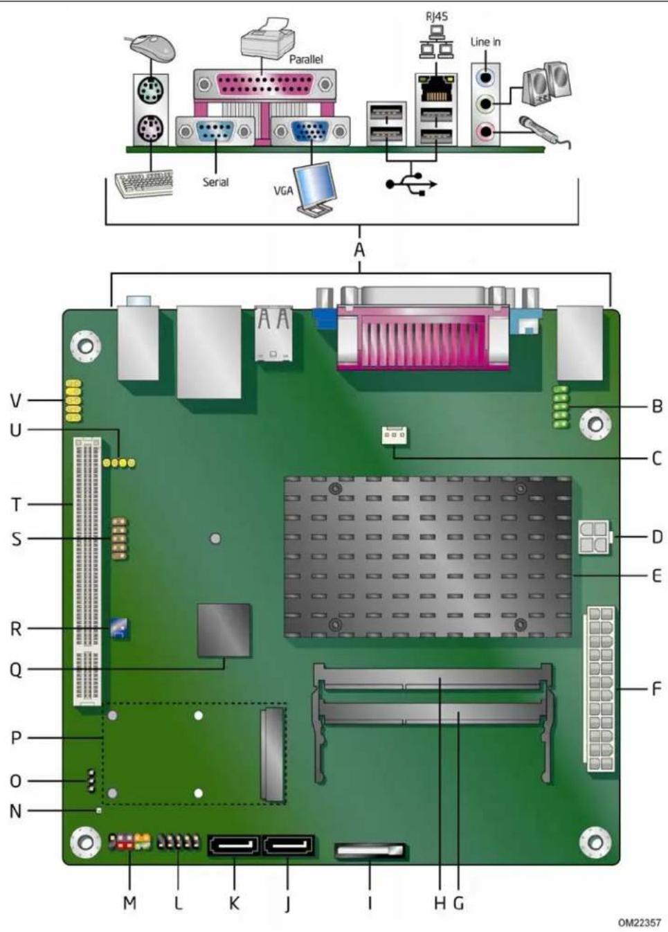
Figure 1 shows the location of the major components on Intel Desktop Board D525MW.
text_image
Parallel Serial VGA RJ45 Line In A V U T S R Q P O N M L K J I H G B C D E F OM22357Figure 1. Intel Desktop Board D525MW Components
Table 2. Intel Desktop Board D525MW Components
| Label | Description |
| A Back panel connectors | |
| B Serial header (COM1) | |
| C | Chassis fan header |
| D 12 V processor core voltage connector (2 x 2 pin) | |
| E | Processor |
| F Main power connector (2 x 12 pin) | |
| G SO-DIMM 0 slot | |
| H SO-DIMM 1 slot | |
| I | Battery |
| J | SATA 1 |
| K | SATA 0 |
| L USB front panel header | |
| M Front panel header | |
| N Standby power indicator | |
| O BIOS configuration jumper block | |
| P PCI Express Mini Card slot | |
| Q Intel NM10 Express Chipset | |
| R Front panel wireless activity LED header | |
| S USB front panel header with Intel Z-U130 USB Solid-State Drive (or compatible device) support | |
| T PCI bus connector | |
| U | S/PDIF header |
| V Front panel audio header | |
Processor
Intel Desktop Board D525MW includes a passively-cooled, dual-core Intel Atom processor with integrated graphics and memory controller. The processor is soldered to the Desktop Board and is not customer upgradeable.

NOTE
The board is designed to be passively cooled in a properly ventilated chassis. Chassis venting locations are recommended above the processor heatsink area for maximum heat dissipation effectiveness.
System Memory

NOTE
To be fully compliant with all applicable Intel ^® SDRAM memory specifications, the board should be populated with DIMMs that support the Serial Presence Detect (SPD) data structure. If your memory modules do not support SPD, you will see a notification to this effect on the screen at power up. The BIOS will attempt to configure the memory controller for normal operation.
The Desktop Board has two 204-pin DDR3 SO-DIMM sockets with gold-plated contacts. These sockets support:
- Support for DDR3 800/1066/1333 MHz SO-DIMMs (DDR3 1066 MHz and DDR3 1333 MHz SO-DIMMs operate at 800 MHz only)
- Serial Presence Detect (SPD) memory only
- Non-ECC memory
- Up to 4 GB of memory
Integrated Graphics Subsystem
The integrated Intel GMA 3150 graphics controller features the following:
• 400 MHz core frequency
• High quality texture engine
— DX9.0c* and OpenGL* 1.4 compliant
— Hardware Pixel Shader 2.0
— Vertex Shader Model 2.0
• 3D Graphics Rendering enhancements
— 1.6 dual texture GigaPixel/s max fill rate
— 16-bit and 32-bit color
— Vertex cache
- Video
— Software DVD at 30 fps full screen
— DVMT support up to 256 MB
• Supports analog displays up to 2048 x 1536 at 75 Hz refresh (QXGA)
Intel® NM10 Express Chipset
The Intel NM10 Express Chipset is a centralized controller for the board's I/O paths. For more information about the Intel NM10 Express Chipset, go to http://www.intel.com/products/chipsets/index.htm?iid=prod+prod_chipset.
Operating System Support
The following Microsoft* operating systems are fully supported by the Desktop Board:
• Microsoft Windows Vista* Basic Service Pack 1
- Microsoft Windows* XP Home Service Pack 3
- Microsoft Windows* 7 Home Basic and Starter
Onboard Audio Subsystem
The Intel Desktop Board D525MW 6-channel (5.1) onboard audio subsystem supports both Intel HD Audio and AC '97 Audio. The subsystem is based on the following components:
• Intel NM10 Express Chipset
• RealTek ALC662 audio codec
The subsystem includes the following headers and connectors:
- Front panel audio header (supports both Intel HD Audio and AC '97), including functionality for:
— Line out (headphones/speaker)
— Microphone in
- Three back panel analog audio jacks
- Onboard S/PDIF output header (3 pin)
The front/back panel audio connectors are configurable through the audio device drivers. Table 3 lists the supported functions of the front panel and back panel jacks.
Table 3. Audio Jack Support
| Audio Jack | Line In | Line/ Front Out | Rear Out | Center/ LFE | Microphone | Headphones |
| Front panel – Green No | Yes No | No No Yes | ||||
| Front panel – Pink No | No No | No Yes No | ||||
| Back panel – Blue Yes | No Yes | No | No | No | ||
| Back panel – Green | No Yes | No No No | Yes | |||
| Back panel – Pink | No | No | No | Yes | Yes | No |
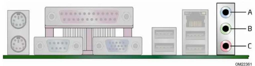
Figure 2 shows the default assignment of the back panel audio connectors.
text_image
A B C OM22361| Item | Description |
| A | Line In |
| B | Line Out |
| C | Mic In |
Figure 2. Back Panel Audio Connectors

NOTE
The back panel audio line out connector is designed to power headphones or amplified speakers only. Poor audio quality occurs if passive (non-amplified) speakers are connected to this output.
Legacy Input/Output (I/O) Controller
The legacy I/O controller provides the following:
- Two serial ports (one via a back panel connector and one via an onboard header)
- One parallel port with Extended Capabilities Port (ECP) and Enhanced Parallel Port (EPP) support via a back panel connector
- Serial IRQ interface compatible with serialized IRQ support for PCI systems
• PS/2-style keyboard and mouse ports
• Intelligent power management, including a programmable wake up event interface
• PCI power management support
The BIOS Setup program provides configuration options for the legacy I/O controller.
LAN Subsystem
The LAN subsystem consists of the following:
• Intel NM10 Express Chipset
• Realtek 8111E Gigabit Ethernet Controller for 10/100/1000 Mbits/s Ethernet LAN connectivity
- RJ-45 LAN connector with integrated status LEDs
Additional features of the LAN subsystem include:
• CSMA/CD protocol engine
• LAN connect interface that supports the ethernet controller
• PCI bus power management
— Supports ACPI technology
— Supports LAN wake capabilities
LAN drivers are available from Intel's World Wide Web site at http://downloadcenter.intel.com/.
Two LEDs are built into the RJ-45 LAN connector located on the back panel (see Figure 3). These LEDs indicate the operating states of the LAN.

text_image
A B OM22360Figure 3. LAN Status LEDs
Table 4 describes the LED states when the board is powered up and the LAN subsystem is operating.
Table 4. LAN Status LEDs
| LED LED Color LED State Indicates | |||
| Activity (A) | Green Blinking LAN activity is occurring. | ||
| Speed (B) | N/A Off 10 | Mbits/s data rate is selected. | |
| Green On 100 Mbits/s data rate is selected. | |||
| Yellow On 1000 Mbits/s data rate is selected. | |||
USB 2.0 Support
The Desktop Board supports up to seven USB 2.0 ports (four ports routed to the back panel and three ports routed to two front panel USB 2.0 headers). One of the front panel USB headers supports an Intel Z-U130 USB Solid-State Drive or compatible device. The USB 2.0 ports are compatible with USB 1.1 devices. USB 1.1 devices will function normally at USB 1.1 speeds.
USB 2.0 support requires both an operating system and drivers that fully support USB 2.0 transfer rates. Disabling High-Speed USB in the BIOS reverts all USB 2.0 ports to USB 1.1 operation. This may be required to accommodate operating systems that do not support USB 2.0.

NOTE
Computer systems that have an unshielded cable attached to a USB port might not meet FCC Class B requirements, even if no device or a low-speed USB device is attached to the cable. Use a shielded cable that meets the requirements for a full-speed USB device.
SATA Interface
The Desktop Board supports two SATA channels (3.0 Gb/s) that support one device per channel. The SATA controller supports IDE and ACHI configuration and can operate in both legacy and native modes.
Expandability
The Desktop Board provides the following expansion capability:
- One PCI connector. The connector can support either a single PCI add-in card or a single- or dual-slot PCI riser card.
• One PCI Express Full-Mini Card slot.
BIOS
The BIOS provides the Power-On Self-Test (POST), the BIOS Setup program, the PCI and SATA auto-configuration utilities, and the video BIOS.
PCI/PCI Express Auto Configuration
If you install a PCI/PCI Express add-in card in your computer, the PCI/PCI Express auto-configuration utility in the BIOS automatically detects and configures the resources (IRQs, DMA channels, and I/O space) for that add-in card. You do not need to run the BIOS Setup program after you install a PCI/PCI Express add-in card.
Security Passwords
The BIOS includes security features that restrict whether the BIOS Setup program can be accessed and who can boot the computer. A supervisor password and a user password can be set for the BIOS Setup and for booting the computer, with the following restrictions:
- The supervisor password gives unrestricted access to view and change all Setup options. If only the supervisor password is set, pressing
at the password prompt of Setup gives the user restricted access to Setup. - If both the supervisor and user passwords are set, you must enter either the supervisor password or the user password to access Setup. Setup options are then available for viewing and changing depending on whether the supervisor or user password was entered.
- Setting a user password restricts who can boot the computer. The password prompt is displayed before the computer is booted. If only the supervisor password is set, the computer boots without asking for a password. If both passwords are set, you can enter either password to boot the computer.
For instructions on resetting the password, see Clearing Passwords on page 40.
Power Management Features
Power management is implemented at several levels, including:
- Software support through the Advanced Configuration and Power Interface (ACPI)
- Hardware support:
— Power connector
— Fan header
— +5 V standby power indicator LED
— LAN Wake capabilities
— Instantly Available PC technology
— Wake from USB
— Wake from PS/2 devices
— PME# wakeup support
— WAKE# signal wakeup support
— Wake from serial port
ACPI
ACPI gives the operating system direct control over the power management and Plug and Play functions of a computer. The use of ACPI with the Desktop Board requires an operating system that provides full ACPI support.
Hardware Support
Fan Header
The Desktop Board has a 3-pin chassis fan header. See Figure 13 on page 37 for the location of the chassis fan header.
+5 V Standby Power Indicator

CAUTION
If the AC power has been switched off and the standby power indicator is still lit, disconnect the power cord before installing or removing any devices connected to the board. Failure to do so could damage the board and any attached devices.
The Desktop Board's standby power indicator, shown in Figure 4, is lit when there is standby power to the system. This includes the DIMM sockets and the PCI bus connector, even though the computer appears to be off.

natural_image
Top-down view of a green computer motherboard with visible components and connectors (no text or symbols)Figure 4. Location of the Standby Power Indicator
For more information on standby current requirements for the Desktop Board, refer to the Technical Product Specification on the Intel Desktop D525MW web page at http://www.intel.com/products/motherboard/D525MW/index.htm.
Instantly Available PC Technology
Instantly Available PC technology enables the board to enter the ACPI S3 (Suspend-to-RAM) sleep-state. While in the ACPI S3 sleep-state, the computer will appear to be off (the hard drive(s) and fan will power off, the front panel power LED will blink). When signaled by a wake-up device or event, the system quickly returns to its last known state.
The board supports the PCI Bus Power Management Interface Specification. Add-in boards that also support this specification can participate in power management and can be used to wake the computer.
The use of Instantly Available PC technology requires operating system support and PCI 2.3 compliant add-in cards and drivers.
LAN Wake Capabilities
The board's LAN wake capabilities enable remote wake-up of the computer through a network. The LAN subsystem network adapter monitors network traffic at the Media Independent Interface. The board supports LAN wake capabilities with ACPI in the following ways:
- By Ping
- By Magic Packet
Upon detecting the configured wake packet type, the LAN subsystem asserts a wake-up signal that powers up the computer.
Wake from USB
USB bus activity wakes the computer from an ACPI S1 or S3 state.

NOTE
Wake from USB requires the use of a USB peripheral that supports wake from USB.
Wake from PS/2 Device
PS/2 keyboard activity wakes the computer from an ACPI S1, S3, S4, or S5 state. However, when the computer is in an ACPI S4 or S5 state, the only PS/2 activity that will wake the computer is the Alt + Print Screen key combination or the Power key available only on some keyboards.
PME# Wakeup Support
When the PME# signal is asserted on the PCI bus, the computer wakes from an ACPI S1, S3, S4, or S5 state.
WAKE# Signal Wakeup Support
When the WAKE# signal is asserted on the PCI Express bus, the computer wakes from an ACPI S1, S3, S4, or S5 state.
Wake from Serial Port
Serial port activity wakes the computer from an ACPI S1 or S3 state.
Battery
A coin-cell battery on the Desktop Board keeps the values in CMOS RAM and the clock current when the computer is turned off. Go to page 41 for instructions on how to replace the battery.
Real-Time Clock
The Desktop Board includes a time-of-day clock and a 100-year calendar. The coin-cell battery keeps the clock current when the computer is turned off.
2 Installing and Replacing Desktop Board Components
This chapter tells you how to:
• Install the I/O shield
• Install and remove the Desktop Board
• Install and remove system memory
- Connect SATA drives
• Install a Wireless LAN card
• Install an Intel Z-U130 USB Solid-State Drive or compatible device
- Connect to internal headers
- Connect chassis fan and power supply cables
- Set the BIOS configuration jumper
- Clear passwords
- Replace the battery
Before You Begin

CAUTION
The procedures in this chapter assume familiarity with the general terminology associated with personal computers and with the safety practices and regulatory compliance required for using and modifying electronic equipment.
Disconnect the computer from its power source and from any telecommunications links, networks, or modems before performing any of the procedures described in this chapter. Failure to disconnect power, telecommunications links, networks, or modems before you open the computer or perform any procedures can result in personal injury or equipment damage. Some circuitry on the board can continue to operate even though the front panel power button is off.
Follow these guidelines before you begin installing the Desktop Board:
• Always follow the steps in each procedure in the correct order.
- Set up a log to record information about your computer, such as model, serial numbers, installed options, and configuration information.
- Electrostatic discharge (ESD) can damage components. Perform the procedures described in this chapter only at an ESD workstation using an antistatic wrist strap and a conductive foam pad. If such a station is not available, you can provide some ESD protection by wearing an antistatic wrist strap and attaching it to a metal part of the computer chassis.

CAUTION
Failure to ensure appropriate airflow may result in reduced performance of both the processor and/or voltage regulator or, in some instances, damage to the board.
All responsibility for determining the adequacy of any thermal or system design remains solely with the reader. Intel makes no warranties or representations that merely following the instructions presented in this document will result in a system with adequate thermal performance.

CAUTION
Ensure that the ambient temperature does not exceed the board's maximum operating temperature. Failure to do so could cause components to exceed their maximum case temperature and malfunction. For information about the maximum operating temperature, see the environmental specifications in the Intel Desktop Board Technical Product Specification.

CAUTION
The board is designed to be passively cooled on a properly ventilated chassis. Chassis venting locations are recommended over the processor, voltage regulator, and system memory areas for maximum heat dissipation effectiveness.
Ensure that proper airflow is maintained around the processor, processor voltage regulator circuit, and the DIMM. Failure to do so may result in damage to these components.

CAUTION
A thermal rating of 85 °C is required for the DIMMs used on this board.
Installation Precautions
When you install and test the Intel Desktop Board, observe all warnings and cautions in the installation instructions.
To avoid injury, be careful of:
- Sharp pins on connectors or headers
- Sharp pins on printed circuit assemblies
- Rough edges and sharp corners on the chassis
• Hot components (such as voltage regulators and heat sinks)
• Damage to wires that could cause a short circuit
Observe all warnings and cautions that instruct you to refer computer servicing to qualified technical personnel.
Prevent Power Supply Overload
Do not overload the power supply output. To avoid overloading the power supply, make sure that the calculated total current loads of all the modules within the computer is less than the output current rating of the power supply.
Observe Safety and Regulatory Requirements
Read and adhere to the instructions in this section and the instructions supplied with the chassis and associated modules. If you do not follow these instructions and the instructions provided by chassis and module suppliers, you increase safety risk and the possibility of noncompliance with regional laws and regulations.
Refer to Appendix B for safety and regulatory requirements.
Installing the I/O Shield
The Desktop Board comes with an I/O shield. When installed in the chassis, the shield blocks radio frequency transmissions, protects internal components from dust and foreign objects, and promotes correct airflow within the chassis.
Install the I/O shield before installing the Desktop Board in the chassis. Place the shield inside the chassis as shown in Figure 5. Press the shield into place so that it fits tightly and securely. If the shield does not fit, obtain a properly-sized shield from the chassis supplier.

natural_image
Diagram showing a computer case with an open door and a closed panel with internal components, connected by directional arrows (no text or symbols)Figure 5. Installing the I/O Shield
Installing and Removing the Desktop Board

CAUTION
Only qualified technical personnel should do this procedure. Disconnect the computer from its power source before performing the procedures described here. Failure to disconnect the power before you open the computer can result in personal injury or equipment damage.
Refer to your chassis manual for instructions on installing and removing the Desktop Board.
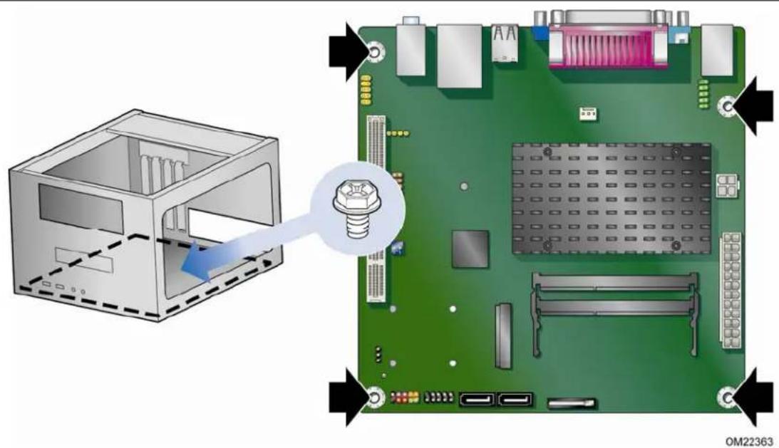
Figure 6 shows the location of the mounting screw holes for Intel Desktop Board D525MW.
text_image
Diagram showing a computer motherboard with an inset view of a CPU socket and a close-up of the screw assembly, labeled 'OM22363'.Figure 6. Intel Desktop Board D525MW Mounting Screw Holes
Installing and Removing Memory

NOTE
To be fully compliant with all applicable Intel SDRAM memory specifications, the boards require DIMMs that support the Serial Presence Detect (SPD) data structure.
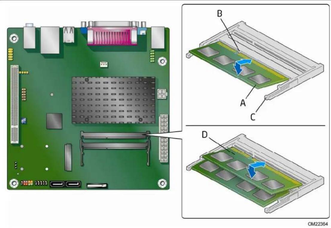
The Desktop Board has two 204-pin DDR3 SO-DIMM sockets that support up to 4 GB of system memory. To install system memory on the Desktop Board, see Figure 7 and follow these steps:
- Observe the precautions in "Before You Begin" on page 23.
- Install the first DIMM (Figure 7, A) in the bottom (DIMM 0) socket. Align the notch in the DIMM with the key in the socket (Figure 7, B), while holding the DIMM with the back edge tilted slightly upwards, insert it in the socket, and gently push the back edge down until it snaps into the retention arms (Figure 7, C).
- If you are installing a second DIMM, repeat Step 2 using the top (DIMM 1) socket (Figure 7, D).
text_image
Technical diagram of a computer motherboard with labeled components and assembly steps, showing internal layout and component positioning.Figure 7. Installing System Memory
To remove an SO-DIMM from a socket, gently spread the socket's retention arms (Figure 7, C) to disengage them from the SO-DIMM.
Connecting SATA Drives
The board has two SATA connectors each supporting one SATA drive. The included SATA cables support the Serial ATA protocol. For correct cable and drive function:
- Observe the precautions in "Before You Begin" on page 23.
- Attach one end of the cable to the connector on the board (Figure 8, A) and connect the other end to the drive (Figure 8, B).
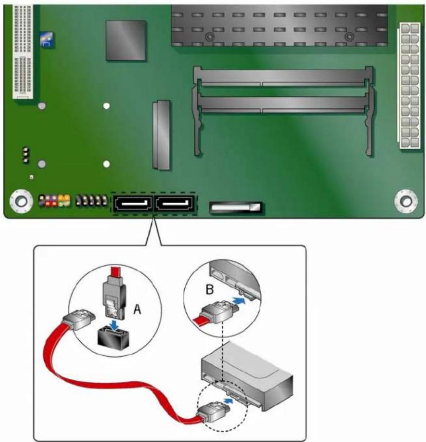
text_image
Diagram showing network device connection with labeled ports A and B, including a red cable and connector layout.OM22366
Figure 8. Connecting the Serial ATA Cable
Installing a Wireless LAN Card in the PCI Express Mini Card Slot
A wireless LAN card can be installed in the Desktop Board's PCI Express Mini Card slot.
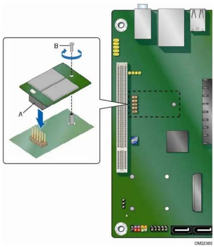
To install a Full-Mini Card wireless LAN card, see Figure 9 and follow these steps:
- Observe the precautions in "Before You Begin" on page 23.
- Insert the wireless LAN card into the PCI Express Mini Card connector (Figure 9, A) at a slightly upward angle.
- Align the card's mounting holes over the board's steel mounting posts (Figure 9, B) and attach the card with the supplied screws.
- Attach your system's antenna wires to the connectors (Figure 9, C) on the wireless LAN card as shown.
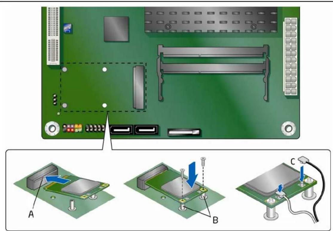
text_image
Diagram showing a green circuit board with labeled components and three-step assembly steps (A, B, C) for device maintenance or installation.OM22372
Figure 9. Installing a Full-Mini Card Wireless LAN Card
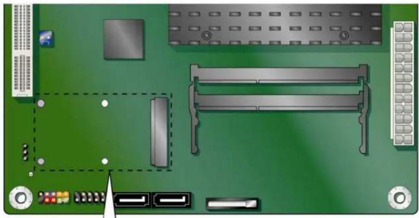
To install a Half-Mini Card wireless LAN card, see Figure 10 and follow these steps:
- Observe the precautions in "Before You Begin" on page 23.
- Insert the plastic Half-Mini Card latch in the mounting holes as shown in Figure 10, A.
- Insert the wireless LAN card into the PCI Express Mini Card connector (Figure 10, B) at a slightly upward angle.
- Align the card's mounting holes (Figure 10, C) with the plastic latch and snap it into place.
- Attach your system's antenna wires to the connectors (Figure 10, D) on the wireless LAN card as shown.
natural_image
Top-down view of a green printed circuit board with various electronic components and connectors (no text or symbols visible)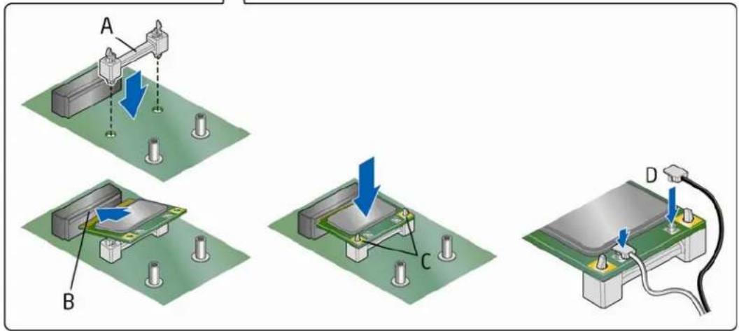
text_image
Diagram illustrating three stages of a mechanical or electrical assembly with labeled components A, B, C, and D.OM22373
Figure 10. Installing a Half-Mini Card Wireless LAN Card

NOTE
External antennas can be connected through the I/O shield by removing one or both of the cut-outs on the I/O shield.
Installing an Intel® Z-U130 USB Solid-State Drive or Compatible Device
An Intel Z-U130 USB Solid-State Drive or compatible device can be installed on the Desktop Board by using the onboard USB 2.0 header indicated in Figure 1, T. This header provides support for the solid state drive.
To install an Intel Z-U130 USB Solid-State Drive or compatible device on the Desktop Board, follow these steps:
- Observe the precautions in "Before You Begin" on page 23.
- Ali gn the connector (Figure 11, A) on the bottom of the solid state drive with the USB 2.0 header on the Desktop Board. The connectors are keyed and will mate correctly when the solid state drive is oriented as shown in Figure 11.
- Secure the solid state drive to the board with the provided screw (Figure 11, B).
text_image
Diagram of an electronic circuit board with labeled components and a magnified view showing component assembly and rotation.Figure 11. Installing an Intel Z-U130 USB Solid-State Drive (or Compatible Device)
Connecting to the Internal Headers
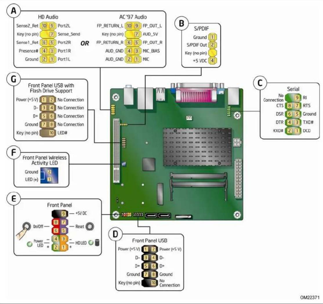
Before connecting cables to the internal headers, observe the precautions in "Before You Begin" on page 23. Figure 12 shows the location of the board's internal headers.
text_image
A HD Audio Sense2_Ret 10 9 Port2L Key (no pin) 7 Sense_Send Sense1_Rot 6 5 Port2R Presence# 4 3 Port1R Ground 2 1 Port1L OR AC '97 Audio FP_RETURN_L 10 9 FP_OUT_L Key (no pin) 7 AUD_5V FP_RETURN_R 6 5 FP_OUT_R AUD_GND 4 3 MIC_BIAS AUD_GND 2 1 MIC B S/PDIF Ground 1 S/PDIF Out 2 Key (no pin) +5 VDC 4 G Front Panel USB with Flash Drive Support Power (+5 V) 1 2 No Connection D- 3 4 No Connection D+ 5 6 No Connection Ground 7 8 No Connection Key (no pin) 10 LED# F Front Panel Wireless Activity LED Ground 2 LED (+) 1 E Front Panel On/Off - +5V DC Power - 8 7 Reset LED + 6 5 HD LED - E Front Panel USB Power (+5 V) 1 2 Power (+5 V) D- 3 4 D- D+ 5 6 D+ Ground 7 8 Ground Key (no pin) 10 No Connection C Serial No 9 RI Connection CTS 8 7 RTS DSR 6 5 Ground DTR 4 3 TXD# RXD# 2 1 DCD D OM22371Figure 12. Internal Headers
Connecting to the Front Panel Audio Header
Figure 12, A shows the location of the front panel audio header. The front panel audio header can be used for both Intel HD Audio and AC '97 Audio.
Table 5 shows the pin assignments for the Intel HD Audio and Table 6 shows the pin assignments for AC '97 Audio.
Table 5. Front Panel Audio Header for Intel HD Audio
| Pin Signal Name Pin Signal Name | ||
| 1 [Port 1] Left channel 2 Ground | ||
| 3 [Port 1] Right channel 4 PRESENCE# (Dongle present) | ||
| 5 [Port 2] Right channel 6 [Port 1] SENSE_RETURN | ||
| 7 SENSE_SEND (Jack detection) 8 Key (no pin) | ||
| 9 [Port 2] Left channel 10 [Port 2] SENSE_RETURN |
Table 6. Front Panel Audio Header for AC '97 Audio
| Pin Signal Name Pin Signal Name | |||||
| 1 | MIC | 2 | AUD_GND | ||
| 3 | MIC_BIAS | 4 | AUD_GND | ||
| 5 | FP_OUT_R | 6 | FP_RETURN_R | ||
| 7 AUD_5V 8 KEY (no pin) | |||||
| 9 | FP_OUT_L | 10 | FP_RETURN_L | ||
Connecting to the S/PDIF Header
Before connecting to the S/PDIF connector, observe the precautions in "Before You Begin" on page 23. See Figure 12, B on page 33 for the location of the S/PDIF header. Table 7 shows the pin assignments for the S/PDIF header.
Table 7. S/PDIF Header
| Pin | Signal Name |
| 1 | Ground |
| 2 | S/PDIF out |
| 3 | Key (no pin) |
| 4 | 5 VDC |
Connecting to the Serial Port Header
Before connecting to the serial port header, observe the precautions in "Before You Begin" on page 23. See Figure 12, C on page 33 for the location of the serial port header.
Table 8 shows the pin assignments for the serial port header.
Table 8. Serial Port Header (COM 1)
| Pin Signal Name Pin Signal Name | ||
| 1 DCD (Data Carrier Detect) 2 RXD# (Receive Data) | ||
| 3 TXD# (Transmit Data) 4 DTR (Data Terminal Ready) | ||
| 5 Ground 6 DSR (Data Set Ready) | ||
| 7 RTS (Request To Send) 8 CTS (Clear To Send) | ||
| 9 RI (Ring Indicator) 10 Key (no pin) | ||
Connecting to the Front Panel USB 2.0 Headers
Before connecting to the USB 2.0 headers, observe the precautions in "Before You Begin" on page 23. See Figure 12, D and G on page 33 for the location of the USB 2.0 headers. Table 9 and Table 10 show the pin assignments for the headers.
The brown USB header (Figure 12, G) supports a single USB port while the black USB header (Figure 12, D) supports two USB ports. The single USB port header is designed to support a Flash Memory Drive such as the Intel Z-U130 USB Solid-State Drive (or compatible device). Refer to Installing an Intel® Z-U130 USB Solid-State Drive or Compatible Device on page 32 for more information.
Table 9. Front Panel USB Header
| Pin Signal Name Pin Signal Name | |||
| 1 | +5 VDC | 2 | +5 VDC |
| 3 | D- | 4 | D- |
| 5 | D+ | 6 | D+ |
| 7 | Ground | 8 | Ground |
| 9 | KEY (no pin) | 10 | No Connect |
Table 10. Front Panel USB Header with Intel Z-U130 USB Solid-State Drive or Compatible Device Support
| Pin Signal Name Pin Signal Name | |||
| 1 | +5 VDC | 2 | No Connect |
| 3 | D- | 4 | No Connect |
| 5 | D+ | 6 | No Connect |
| 7 | Ground | 8 | No Connect |
| 9 | KEY (no pin) | 10 | LED# |
Connecting to the Front Panel Header
Before connecting to the front panel header, observe the precautions in "Before You Begin" on page 23. See Figure 12, E on page 33 for the location of the front panel header.
Table 11 shows the pin assignments for the front panel header.
Table 11. Front Panel Header Signal Names
| Pin | Signal In/Out Description Pin | Signal | In/Out | Description | |||
| Hard Drive Activity LED Power LED | |||||||
| 1 | HD_PWR | Out | Hard disk LED pull-up (330 Ω) to +5 V | 2 | HDR_BLNK_GRN | Out | Front panel green LED |
| 3 | HDA# | Out | Hard disk active LED | 4 | HDR_BLNK_YEL | Out | Front panel yellow LED |
| Reset Switch On/Off Switch | |||||||
| 5 | Ground | Ground 6 | SWITCH_ON# In | Power switch | |||
| 7 | FP_RESET# | In | Reset switch | 8 | Ground | Ground | |
| Power | Not Connected | ||||||
| 9 | +5 V | Power | 10 | N/C | No pin | ||
Connecting to the Front Panel Wireless Activity LED Header
Before connecting to the front panel wireless activity LED header, observe the precautions in "Before You Begin" on page 23. See Figure 12, F on page 33 for the location of the front panel wireless activity LED header.
Table 12 shows the pin assignments for the front panel wireless activity LED header.
Table 12. Front Panel Wireless Activity LED Header
| Pin | Signal Name |
| 1 | LED (+) |
| 2 | Ground |
Connecting a Chassis Fan
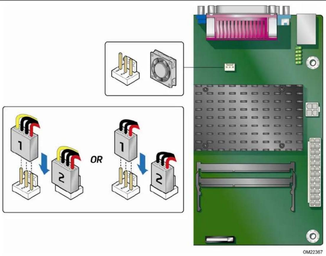
Figure 13 shows the location of the chassis fan header. Connect the chassis fan cable to this header.
text_image
OR OM22367Figure 13. Location of the Chassis Fan Header
Connecting a Power Supply

CAUTION
Failure to connect an appropriate power supply to the Desktop Board may result in damage to the board or the system may not function properly.
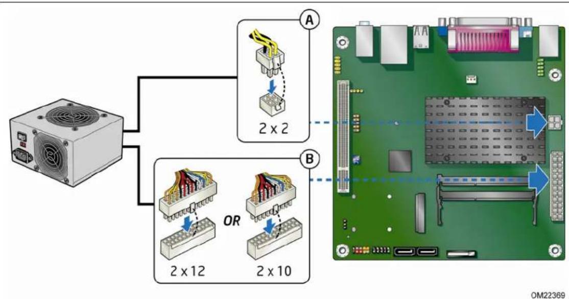
Figure 14 shows the location of the power connectors.
flowchart
graph TD
    A["Power Supply"] --> B["2x2 Component"]
    B --> C["2x12 Components"]
    B --> D["2x10 Components"]
    C --> E["Computer Board"]
    D --> E
    style A fill:#f9f,stroke:#333
    style B fill:#ccf,stroke:#333
    style C fill:#cfc,stroke:#333
    style D fill:#fcc,stroke:#333
Figure 14. Connecting Power Supply Cables
- Observe the precautions in "Before You Begin" on page 23.
- Connect the main power supply cable to the 2 x 12 pin connector (Figure 14, B).
- Connect the 12 V processor core voltage power supply cable to the 2 x 2 pin connector (Figure 14, A).
Setting the BIOS Configuration Jumper

NOTE
Always turn off the power and unplug the power cord from the computer before changing a jumper. Moving the jumper with the power on may result in unreliable computer operation.
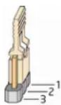
Figure 15 shows the location of the Desktop Board's BIOS configuration jumper block.

text_image
1 2 3 OM22358Figure 15. BIOS Configuration Jumper Block
The three-pin BIOS configuration jumper block enables board operating modes. Table 13 shows the jumper settings for each of the available modes.
Figure 15 shows the location of the Desktop Board's BIOS configuration jumper block.
Table 13. Jumper Settings for the BIOS Setup Program Modes
| Jumper Setting | Mode | Description |
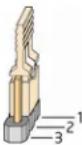 | Normal (default) (1-2) | The BIOS uses the current configuration and passwords for booting. |
 | Configure (2-3) After the | Power-On Self-Test (POST) runs, the BIOS displays the Maintenance Menu. Use this menu to clear passwords. |
 | Recovery (None) The BIOS recovers data from a recovery diskette in the event of a failed BIOS update. | |
Clearing Passwords
This procedure assumes that the board is installed in the computer and the configuration jumper is set to normal mode.
- Observe the precautions in "Before You Begin" on page 23.
- Turn off all peripheral devices connected to the computer. Turn off the computer. Disconnect the computer's power cord from the AC power source (wall outlet or power adapter).
- Remove the computer cover.
- Find the configuration jumper block (see Figure 15).
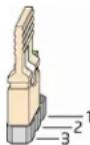
- Place the jumper on pins 2-3 as shown below.
-
Replace the cover, plug in the computer, turn on the computer, and allow it to boot.
-
The computer starts the Setup program. Setup displays the Maintenance menu.
-
Use the arrow keys to select Clear Passwords. Press
and Setup displays a pop-up screen requesting that you confirm clearing the password. Select Yes and press . Setup displays the maintenance menu again. -
Press
to save the current values and exit Setup. -
Turn off the computer. Disconnect the computer's power cord from the AC power source.
-
Remove the computer cover.
-
To restore normal operation, place the jumper on pins 1-2 as shown below.
- Replace the cover, plug in the computer, and turn on the computer.
Replacing the Battery
A coin-cell battery powers the Desktop Board's real-time clock and CMOS memory. When the computer is not plugged into a wall socket, the battery has an estimated life of three years. When the computer is plugged in, the standby current from the power supply extends the life of the battery. The clock is accurate to ± 13 minutes/year at 25^ with 3.3 VSB applied.
When the voltage drops below a certain level, the BIOS Setup program settings stored in CMOS RAM (for example, the date and time) might not be accurate. Replace the battery with an equivalent one. Figure 16 on page 45 shows the location of the battery.

CAUTION
Risk of explosion if the battery is replaced with an incorrect type. Batteries should be recycled where possible. Disposal of used batteries must be in accordance with local environmental regulations.

PRÉCAUTION
- Observe the precautions in "Before You Begin" (see page 23).
- Turn off all peripheral devices connected to the computer. Disconnect the computer's power cord from the AC power source (wall outlet or power adapter).
- Remove the computer cover.
- Locate the battery on the board (see Figure 16).
- Push the battery retention clip aside and remove the battery from the connector as shown in Figure 16. Note the orientation of the "+" and "-" on the battery.
- Install the new battery in the connector, making sure to orient the "+" and "-" correctly.
- Replace the computer cover.

text_image
Technical diagram showing assembly of a device with labeled components and directional arrows indicating motion or assembly.Figure 16. Removing the Battery
Intel Desktop Board D525MW Product Guide
3 Updating the BIOS
The BIOS Setup program can be used to view and change the BIOS settings for the computer. You can access the BIOS Setup program by pressing the
This chapter tells you how to update the BIOS by either using the Intel Express BIOS Update utility or the Iflash Memory Update utility, and how to recover the BIOS if an update fails.
Updating the BIOS with the Intel® Express BIOS Update Utility
With the Intel Express BIOS Update utility you can update the system BIOS while in the Windows environment. The BIOS file is included in an automated update utility that combines the functionality of the Intel® Flash Memory Update Utility and the ease of use of Windows-based installation wizards.
To update the BIOS with the Intel Express BIOS Update utility:
- Go to http://www.intel.com/p/en_US/support?iid=hdr+support.
- Navigate to the Intel Desktop Board D525MW page, click "[view] Latest BIOS updates," and select the Express BIOS Update utility file.
- Download the file to your hard drive. (You can also save this file to a removable USB device. This is useful if you are updating the BIOS for multiple identical systems.)
- Close all other applications. This step is required. Your system will be rebooted at the last Express BIOS Update window.
- Double-click the executable file from the location on your hard drive where it was saved. This runs the update program.
- Follow the instructions provided in the dialog boxes to complete the BIOS update.
Updating the BIOS with the Iflash Memory Update Utility
You can use the information in this section to update the BIOS using the Iflash Memory Update Utility.
Obtaining the BIOS Update File
You can update to a new version of the BIOS by using the Iflash BIOS update file.
The Iflash BIOS update file is a compressed file that contains the files you need to update the BIOS. The Iflash BIOS update file contains:
- New BIOS file
• Intel Flash Memory Update Utility
You can obtain either of these files through your computer supplier or by navigating to the Intel Desktop Board D525MW page at http://www.intel.com/p/en_US/support?iid=hdr+support.
Navigate to the Intel Desktop D525MW page, click "[view] Latest BIOS updates," and select the Iflash BIOS Update utility file.

CAUTION
Do not interrupt the process or the system may not function properly.
Using the Iflash Memory Update Utility
With the Iflash Memory update utility you can update the system BIOS from a bootable USB flash drive or other bootable USB media. The Iflash BIOS update files can be extracted locally to your hard drive and copied to a bootable USB flash drive or other bootable USB media.

NOTE
Review the instructions distributed with the update utility before attempting a BIOS update.

CAUTION
Do not interrupt the process or the system may not function properly.
- Uncompress the BIOS update file and copy the .BIO file and IFLASH.EXE to a bootable USB flash drive or other bootable USB media.
- Configure the BIOS or use the F10 key option during POST to boot to the USB device.
- Manually run the IFLASH.EXE file from the USB device and manually update the BIOS.
Recovering the BIOS
It is unlikely that anything will interrupt a BIOS update; however, if an interruption occurs, the BIOS could be damaged. Table 14 lists the drives and media types that can and cannot be used for BIOS recovery. The BIOS recovery media does not have to be bootable.
Table 14. Acceptable Drives/Media Types for BIOS Recovery
| Media Type Can be Used for BIOS Recovery? | |
| CD-ROM drive connected to the SATA interface Yes | |
| USB removable drive (a USB Flash Drive, for example) Yes | |
| USB diskette drive (with a 1.44 MB diskette) No | |
| USB hard disk drive No |

NOTE
For more information about BIOS update and recovery, go to http://support.intel.com/support/motherboards/desktop/sb/CS-022312.htm.
Intel Desktop Board D525MW Product Guide
A Board Status and Error Messages
This appendix describes status and error messages generated by the Desktop Board's BIOS. The BIOS indicates these error messages with front-panel Power LED blink codes, speaker beep codes, and by displaying text on the video monitor.
BIOS Beep Codes
The BIOS uses audible beep codes to signal status messages and error messages indicating recoverable errors that occur during the POST. The beep codes are listed in Table 15. These beep codes can be heard through a speaker attached to the board's line out audio jack (see Figure 2, B on page 15).
Table 15. BIOS Beep Codes
| Type Pattern Frequency | ||
| F2 Setup/F10 Boot Menu Prompt | One 0.5-second beep when the BIOS is ready to accept keyboard input | 932 Hz |
| Video error On-off (1.0 second each) two times, then a 2.5-second pause (off); the entire pattern repeats (beeps and pause) once and the BIOS will continue to boot. | 932 HzWhen no VGA option ROM is found. | |
| Memory error On-off (1.0 second each) three times, then a 2.5-second pause (off); the entire pattern repeats (beeps and pause) until the system is powered off. | 932 Hz | |
| Thermal trip warning | Alternate high and low beeps (1.0 second each) for eight beeps, followed by system shut down. | High beep 2000 HzLow beep 1500 Hz |
BIOS Front-panel Power LED Blink Codes
The BIOS also blinks the front-panel power LED to signal status messages and error messages indicating certain recoverable errors that occur during the POST. The blink codes are listed in Table 16.
Table 16. BIOS Front-panel Power LED Blink Codes
| Type Pattern Note | ||
| BIOS update in progress | Off when the update begins, then on for 0.5 second, and then off for 0.5 second.The pattern repeats until the BIOS update is complete. | |
| Video error On-off (1.0 second each) two times, then a 2.5-second pause (off); the entire pattern repeats (blinks and pause) until the system is powered off. | When no VGA option ROM is found. | |
| Memory error On-off (1.0 second each) three times, then a 2.5-second pause (off); the entire pattern repeats (blinks and pause) until the system is powered off. | ||
| Thermal trip warning Each beep will be accompanied by the following blink pattern: 0.25 second on, 0.25 second off, 0.25 second on, 0.25 second off. This results in a total of 16 blinks followed by system shut down. | ||
POST Error Messages
The BIOS also displays error messages on the video monitor when certain recoverable errors occur during the POST. Table 17 lists the error messages with a brief description of each.
Table 17. POST Error Messages
| Error Message Explanation | |
| CMOS Battery Low The battery may be losing power. | |
| CMOS Checksum Bad The CMOS checksum is incorrect. The CMOS memory may have been corrupted. Run Setup to reset values. | |
| Memory Size Decreased Memory size has decreased since the last boot. If no memory was removed, then memory may be bad. | |
| No Boot Device Available System did not find a device to boot. | |
B Regulatory Compliance
This appendix contains the following regulatory compliance information for Intel Desktop Board D525MW:
- Safety standards
• European Union Declaration of Conformity statement
• Product Ecology statements
• Electromagnetic Compatibility (EMC) regulations
• Product certifications
Safety Standards
Intel Desktop Board D525MW complies with the safety standards stated in Table 18 when correctly installed in a compatible host system.
Table 18. Safety Standards
| Regulation | Title |
| CSA/UL 60950-1 Information | Technology Equipment – Safety - Part 1: General Requirements (USA and Canada) |
| EN 60950-1 Information Technology | nology Equipment – Safety - Part 1: General Requirements (European Union) |
| IEC 60950-1 Information Technology | nology Equipment – Safety - Part 1: General Requirements (International) |
Battery Caution
There is insufficient space on this Desktop Board to provide instructions for replacing and disposing of the Lithium ion coin cell battery. For system safety certification, the statement below or an equivalent statement is required to be permanently and legibly marked on the chassis near the battery.
A suitable caution label is included with Intel Desktop Board D525MW.

CAUTION
Risk of explosion if the battery is replaced with an incorrect type. Batteries should be recycled where possible. Disposal of used batteries must be in accordance with local environmental regulations.
For information about replacing the battery, go to page 41.
European Union Declaration of Conformity Statement
We, Intel Corporation, declare under our sole responsibility that the product Intel ^® Desktop Board D525MW is in conformity with all applicable essential requirements necessary for CE marking, following the provisions of the European Council Directives 2004/108/EC (EMC Directive), 2006/95/EC (Low Voltage Directive), and 2002/95/EC (ROHS Directive).
The product is properly CE marked demonstrating this conformity and is for distribution within all member states of the EU with no restrictions.
CE
This product follows the provisions of the European Directives 2004/108/EC, 2006/95/EC and 2002/95/EC.
Čeština Tento výrobek odpovídá požadavkům evropských směrnic 2004/108/EC, 2006/95/EC a 2002/95/EC.
Dansk Dette produkt er i overensstemmelse med det europæiske direktiv 2004/108/EC, 2006/95/EC & 2002/95/EC.
Dutch Dit product is in navolging van de bepalingen van Europees Directief 2004/108/EC, 2006/95/EC & 2002/95/EC.
Eesti Antud toode vastab Euroopa direktiivides 2004/108/EC, ja 2006/95/EC ja 2002/95/EC kehtestatud nõuetele.
Suomi Tämä tuote noudattaa EU-direktiivin 2004/108/EC, 2006/95/EC & 2002/95/EC määräyksiä.
Français Ce produit est conforme aux exigences de la Directive Européenne 2004/108/EC, 2006/95/EC & 2002/95/EC.
Deutsch Dieses Produkt entspricht den Bestimmungen der Europäischen Richtlinie 2004/108/EC, 2006/95/EC & 2002/95/EC.
Ελληνικά Το παρόν προϊόν ακολουθεί τις διατάξεις των Ευρωπαϊκών Οδηγιών 2004/108/EC, 2006/95/EC και 2002/95/EC.
Magyar E termék megfelel a 2004/108/EC, 2006/95/EC és 2002/95/EC Európai Irányelv előírásainak.
Icelandic Pessi vara stenst reglugerð Evrópska Efnahags Bandalagsins númer 2004/108/EC, 2006/95/EC, & 2002/95/EC.
Italiano Questo prodotto è conforme alla Direttiva Europea 2004/108/EC, 2006/95/EC & 2002/95/EC.
Latviešu Šis produkts atbilst Eiropas Direktīvu 2004/108/EC, 2006/95/EC un 2002/95/EC noteikumiem.
Lietuvių Šis produktas atitinka Europos direktyvų 2004/108/EC, 2006/95/EC, ir 2002/95/EC nuostatas.
Malti Dan il-prodott hu konformi mal-provvedimenti tad-Direttivi Ewropej 2004/108/EC, 2006/95/EC u 2002/95/EC.
Norsk Dette produktet er i henhold til bestemmelsene i det europeiske direktivet 2004/108/EC, 2006/95/EC & 2002/95/EC.
Polski Niniejszy produkt jest zgodny z postanowieniami Dyrektyw Unii Europejskiej 2004/108/EC, 206/95/EC i 2002/95/EC.
Product Ecology Statements
The following information is provided to address worldwide product ecology concerns and regulations.
Recycling Considerations
As part of its commitment to environmental responsibility, Intel has implemented the Intel® Product Recycling Program to allow retail consumers of Intel's branded products to return used products to selected locations for proper recycling.
Please consult http://intel.com/intel/other/ehs/product_ecology
for the details of this program, including the scope of covered products, available locations, shipping instructions, terms and conditions, etc.
中文
请参考http://intel.com/intel/other/ehs/product_ecology
Intel Desktop Board D525MW is a China RoHS-compliant product.
The China Ministry of Information Industry (MII) stipulates that a material Self Declaration Table (SDT) must be included in a product's user documentation. The SDT for Intel Desktop Board D525MW is shown in Figure 17.
Management Methods on Control of Pollution from
Electronic Information Products
(China RoHS declaration)
产品中有毒有害物质的名称及含量
| 部件名称(Parts) | 有毒有害物质或元素 | |||||
| 铅(Pb) | 汞(Hg) | 镉(Cd) | 六价铬(Cr6+) | 多溴联苯(PBB) | 多溴二苯醚(PBDE) | |
| 主板组件Motherboard Assembly | × | ○ | ○ | ○ | ○ | ○ |
| ○:表示该有毒有害物质在该部件所有均质材料中的含量均在SJ/T 11363-2006标准规定的限量要求以下。○:Indicates that this hazardous substance contained in all homogeneous materials of this part is below the limit requirement in SJ/T 11363-2006.×:表示该有毒有害物质至少在该部件的某一均质材料中的含量超出SJ/T 11363-2006标准规定的限量要求。×:Indicates that this hazardous substance contained in at least one of the homogeneous materials of this part is above the limit requirement in SJ/T 11363-2006.对销售之日的所售产品,本表显示我公司供应链的电子信息产品可能包含这些物质。注意:在所售产品中可能会也可能不会含有有所列的部件.This table shows where these substances may be found in the supply chain of our electronic information products, as of the date of sale of the enclosed product. Note that some of the component types listed above may or may not be a part of the enclosed product. | ||||||
Figure 17. Intel Desktop Board D525MW China RoHS Material Self Declaration Table
EMC Regulations
Intel Desktop Board D525MW complies with the EMC regulations stated in Table 19 when correctly installed in a compatible host system.
Table 19. EMC Regulations
| Regulation | Title |
| FCC 47 CFR Part 15, Subpart B | Title 47 of the Code of Federal Regulations, Part 15, Subpart B, Radio Frequency Devices. (USA) |
| ICES-003 Interference-Causing Equipment Standard, Digital Apparatus. (Canada) | |
| EN55022 Limits and methods of measurement of Radio Interference Characteristics of Information Technology Equipment. (European Union) | |
| EN55024 Information Technology Equipment - Immunity Characteristics Limits and methods of measurement. (European Union) | |
| EN55022 Australian Communications Authority, Standard for Electromagnetic Compatibility. (Australia and New Zealand) | |
| CISPR 22 Limits and methods of measurement of Radio Disturbance Characteristics of Information Technology Equipment. (International) | |
| CISPR 24 Information Technology Equipment - Immunity Characteristics - Limits and Methods of Measurement. (International) | |
| VCCI V-3, V-4 Voluntary Control for Interference by Information Technology Equipment. (Japan) | |
| KN-22, KN-24 Korean Communications Commission - Framework Act on Telecommunications and Radio Waves Act. (South Korea) | |
| CNS 13438 Bureau of Standards, Metrology and Inspection. (Taiwan) | |
FCC Declaration of Conformity
This device complies with Part 15 of the FCC Rules. Operation is subject to the following two conditions: (1) this device may not cause harmful interference, and (2) this device must accept any interference received, including interference that may cause undesired operation.
For questions related to the EMC performance of this product, contact:
Intel Corporation, 5200 N.E. Elam Young Parkway, Hillsboro, OR 97124 1-800-628-8686
This equipment has been tested and found to comply with the limits for a Class B digital device, pursuant to Part 15 of the FCC Rules. These limits are designed to provide reasonable protection against harmful interference in a residential installation. This equipment generates, uses, and can radiate radio frequency energy and, if not installed and used in accordance with the instructions, may cause harmful interference to radio communications. However, there is no guarantee that interference will not occur in a particular installation. If this equipment does cause harmful interference to radio or television reception, which can be determined by turning the equipment off
and on, the user is encouraged to try to correct the interference by one or more of the following measures:
- Reorient or relocate the receiving antenna.
- Increase the separation between the equipment and the receiver.
- Connect the equipment to an outlet on a circuit other than the one to which the receiver is connected.
- Consult the dealer or an experienced radio/TV technician for help.
Any changes or modifications to the equipment not expressly approved by Intel Corporation could void the user's authority to operate the equipment.
Tested to comply with FCC standards for home or office use.
Canadian Department of Communications Compliance Statement
This digital apparatus does not exceed the Class B limits for radio noise emissions from digital apparatus set out in the Radio Interference Regulations of the Canadian Department of Communications.
Japan Statement translation: This is a Class B product based on the standard of the Voluntary Control Council for Interference from Information Technology Equipment (VCCI). If this is used near a radio or television receiver in a domestic environment, it may cause radio interference. Install and use the equipment according to the instruction manual.
Korea Class B Statement
Korea Class B Statement translation: This equipment is for home use, and has acquired electromagnetic conformity registration, so it can be used not only in residential areas, but also other areas.
Ensure Electromagnetic Compatibility (EMC) Compliance
Before computer integration, make sure that the power supply and other modules or peripherals, as applicable, have passed Class B EMC testing and are marked accordingly.
Pay close attention to the following when reading the installation instructions for the host chassis, power supply, and other modules:
• Product certifications or lack of certifications
• External I/O cable shielding and filtering
- Mounting, grounding, and bonding requirements
• Keying connectors when mating the wrong connectors could be hazardous
If the power supply and other modules or peripherals, as applicable, are not Class B EMC compliant before integration, then EMC testing may be required on a representative sample of the newly completed computer.
Product Certifications
Board-Level Certifications
Intel Desktop Board D525MW has the regulatory compliance marks shown in Table 20.
Table 20. Regulatory Compliance Marks
| Description | Mark |
| UL joint US/Canada Recognized Component mark. Includes adjacent UL file number for Intel Desktop Boards: E210882. |  |
| FCC Declaration of Conformity logo mark for Class B equipment. |  |
| CE mark. Declaring compliance to European Union (EU) EMC directive, Low Voltage directive, and RoHS directive. |  |
| Australian Communications Authority (ACA) and New Zealand Radio Spectrum Management (NZ RSM) C-tick mark. Includes adjacent Intel supplier code number, N-232. |  |
| Japan VCCI (Voluntary Control Council for Interference) mark. |  |
| S. Korea KCC (Korean Communications Commission) mark. Includes adjacent KCC certification number: CPU-D525MW (B). |  |
| Taiwan BSMI (Bureau of Standards, Metrology and Inspections) mark. Includes adjacent Intel company number, D33025. |  |
| Printed wiring board manufacturer's recognition mark. Consists of a unique UL recognized manufacturer's logo, along with a flammability rating (solder side). | V-0 |
| China RoHS/Environmentally Friendly Use Period Logo: This is an example of the symbol used on Intel Desktop Boards and associated collateral. The color of the mark may vary depending upon the application. The Environmental Friendly Usage Period (EFUP) for Intel Desktop Boards has been determined to be 10 years. |  |
Chassis- and Component-Level Certifications
Ensure that the chassis and certain components; such as the power supply, peripheral drives, wiring, and cables; are components certified for the country or market where used. Agency certification marks on the product are proof of certification. Typical product certifications include:
In Europe
The CE mark indicates compliance with all applicable European requirements. If the chassis and other components are not properly CE marked, a supplier's Declaration of Conformity statement to the European EMC directive, Low Voltage directive (as applicable), and ROHS directive, should be obtained. Additionally, other directives, such as the Radio and Telecommunications Terminal Equipment (R&TTE) directive may also apply depending on product features.
In the United States
A certification mark by a Nationally Recognized Testing Laboratory (NRTL) such as UL, CSA, or ETL signifies compliance with safety requirements. Wiring and cables must also be UL listed or recognized and suitable for the intended use. The FCC Class B logo for home or office use signifies compliance with electromagnetic interference (EMI) requirements.
In Canada
A nationally recognized certification mark such as CSA or cUL signifies compliance with safety requirements. The Industry Canada statement on page 60 of this product guide demonstrates compliance with Canadian EMC regulations.
ENERGY STAR\*, e-Standby, and ErP Compliance
Intel Desktop Board D525MW meets the ENERGY STAR requirements listed in Table 21 when used in corresponding system configurations.
Table 21. ENERGY STAR Requirements
| ENERGY STAR Specification | Computer Type | Required States | Capability Adjustments | Typical Electricity Consumption (TEC) Criteria |
| v4.0 | Desktop | College State (Cat A)Sleep Mode Standby Level | With and without Wake On LAN (Sleep, Standby) | N/A |
| v4.0 | Integrated Computer | |||
| v5.0 | Desktop | Off Mode Sleep Mode Desktop Idle State Active State | With and without additional internal storage | Cat A under “desktop conventional” and “desktop proxying” operational mode weightings |
| v5.0 | Integrated Computer | |||
| v5.0 Thin Client | Off Mode | Sleep Mode Idle State (Cat B) | With and without Wake On LAN (Sleep, Standby) | N/A |
For information about ENERGY STAR requirements and recommended configurations, go to http://www.intel.com/go/energystar.
The Desktop Board also meets the following international requirements:
• Republic of Korea e-Standby program
• European Union Energy using Products (ErP) directive