DP55WG - Motherboard INTEL - Free user manual and instructions
Find the device manual for free DP55WG INTEL in PDF.

User questions about DP55WG INTEL
0 question about this device. Answer the ones you know or ask your own.
Ask a new question about this device
Download the instructions for your Motherboard in PDF format for free! Find your manual DP55WG - INTEL and take your electronic device back in hand. On this page are published all the documents necessary for the use of your device. DP55WG by INTEL.
USER MANUAL DP55WG INTEL
| Revision | Revision History Date | |||
| -001 | First release of the Intel | ^® Desktop Board DP55WG Product Guide July 2009 | ||
| -002 | Second release of the Intel | ^® Desktop Board DP55WG Product Guide December 2009 | ||
| -003 | Third release of the Intel | ^® Desktop Board DP55WG Product Guide April 2010 | ||
If an FCC declaration of conformity marking is present on the board, the following statement applies:
FCC Declaration of Conformity
This device complies with Part 15 of the FCC Rules. Operation is subject to the following two conditions: (1) this device may not cause harmful interference, and (2) this device must accept any interference received, including interference that may cause undesired operation.
For questions related to the EMC performance of this product, contact:
Intel Corporation, 5200 N.E. Elam Young Parkway, Hillsboro, OR 97124 1-800-628-8686
This equipment has been tested and found to comply with the limits for a Class B digital device, pursuant to Part 15 of the FCC Rules. These limits are designed to provide reasonable protection against harmful interference in a residential installation. This equipment generates, uses, and can radiate radio frequency energy and, if not installed and used in accordance with the instructions, may cause harmful interference to radio communications. However, there is no guarantee that interference will not occur in a particular installation. If this equipment does cause harmful interference to radio or television reception, which can be determined by turning the equipment off and on, the user is encouraged to try to correct the interference by one or more of the following measures:
• Reorient or relocate the receiving antenna.
- Increase the separation between the equipment and the receiver.
- Connect the equipment to an outlet on a circuit other than the one to which the receiver is connected.
- Consult the dealer or an experienced radio/TV technician for help.
Any changes or modifications to the equipment not expressly approved by Intel Corporation could void the user's authority to operate the equipment.
Tested to comply with FCC standards for home or office use.
Canadian Department of Communications Compliance Statement
This digital apparatus does not exceed the Class B limits for radio noise emissions from digital apparatus set out in the Radio Interference Regulations of the Canadian Department of Communications.
INFORMATION IN THIS DOCUMENT IS PROVIDED IN CONNECTION WITH INTEL® PRODUCTS. NO LICENSE, EXPRESS OR IMPLIED, BY ESTOPPEL OR OTHERWISE, TO ANY INTELLECTUAL PROPERTY RIGHTS IS GRANTED BY THIS DOCUMENT. EXCEPT AS PROVIDED IN INTEL'S TERMS AND CONDITIONS OF SALE FOR SUCH PRODUCTS, INTEL ASSUMES NO LIABILITY WHATSOEVER, AND INTEL DISCLAIMS ANY EXPRESS OR IMPLIED WARRANTY, RELATING TO SALE AND/OR USE OF INTEL PRODUCTS INCLUDING LIABILITY OR WARRANTIES RELATING TO FITNESS FOR A PARTICULAR PURPOSE, MERCHANTABILITY, OR INFRINGEMENT OF ANY PATENT, COPYRIGHT OR OTHER INTELLECTUAL PROPERTY RIGHT. Intel products are not intended for use in medical, life saving, or life sustaining applications. Intel may make changes to specifications and product descriptions at any time, without notice.
Intel Desktop Board DP55WG may contain design defects or errors known as errata which may cause the product to deviate from published specifications. Current characterized errata are available on request.
Contact your local Intel sales office or your distributor to obtain the latest specifications and before placing your product order.
Copies of documents which have an ordering number and are referenced in this document, or other Intel literature, may be obtained from Intel Corporation by going to the World Wide Web site at: http://www.intel.com/ or by calling 1-800-548-4725.
Intel and the Intel logo are trademarks of Intel Corporation in the United States and other countries.
* Other names and brands may be claimed as the property of others.
Copyright © 2009, 2010, Intel Corporation. All rights reserved.
This Product Guide gives information about board layout, component installation, BIOS update, and regulatory requirements for Intel ^® Desktop Board DP55WG.
Intended Audience
The Product Guide is intended for technically qualified personnel. It is not intended for general audiences.
Use Only for Intended Applications
All Intel Desktop Boards are evaluated as Information Technology Equipment (I.T.E.) for use in personal computers (PC) for installation in homes, offices, schools, computer rooms, and similar locations. The suitability of this product for other PC or embedded non-PC applications or other environments, such as medical, industrial, alarm systems, test equipment, etc. may not be supported without further evaluation by Intel.
Document Organization
The chapters in this Product Guide are arranged as follows:
1 Desktop Board Features: a summary of product features
2 Installing and Replacing Desktop Board Components: instructions on how to install the Desktop Board and other hardware components
3 Updating the BIOS: instructions on how to update the BIOS
4 Configuring for RAID Using Intel ^® Matrix Storage Technology: information about configuring your system for RAID
A Error Messages and Indicators: information about BIOS error messages and beep codes
B Regulatory Compliance: describes the board's adherence to safety standards and EMC regulations and its product certifications
Conventions
The following conventions are used in this manual:

CAUTION
Cautions warn the user about how to prevent damage to hardware or loss of data.

NOTE
Notes call attention to important information.
Terminology
The table below gives descriptions of some common terms used in the product guide.
| Term | Description | ||
| GB | Gigabyte | (1,073,741,824 | bytes) |
| GHz Gigahertz | (one billion hertz) | ||
| KB Kilobyte | (1024 bytes) | ||
| MB Megabyte | (1,048,576 bytes) | ||
| Mb | Megabit | (1,048,576 | bits) |
| MHz Megahertz | (one million hertz) | ||
1 Desktop Board Features
Supported Operating Systems....11
Desktop Board Components....12
Processor....14
Main Memory....15
Intel® P55 Express Chipset....16
Audio Subsystem 16
LAN Subsystem 16
USB 2.0 Support....17
Serial ATA Support....17
Legacy I/O....19
Expandability....19
BIOS....19
Serial ATA Auto Configuration....19
PCI Express* Auto Configuration....19
Security Passwords....20
Hardware Management....20
Hardware Monitoring and Fan Speed Control 20
Intel® Precision Cooling Technology 20
Chassis Intrusion....21
Power Management....21
Software Support 21
ACPI....21
Hardware Support 21
Power Connectors 21
Fan Headers....22
LAN Wake Capabilities....22
Instantly Available PC Technology....22
+5 V Standby Power Indicator....23
Wake from USB 24
PME# Signal Wake-up Support....24
WAKE# Signal Wake-up Support 24
Wake from Consumer IR 24
ENERGY STAR*, e-Standby, and EuP Compliance 24
Onboard Power Button....25
Processor and Voltage Regulator LEDs 26
Back to BIOS Button....27
Speaker....28
Battery 28
Real-Time Clock....28
2 Installing and Replacing Desktop Board Components
Before You Begin 29
Installation Precautions....30
Prevent Power Supply Overload 30
Observe Safety and Regulatory Requirements....30
Installing the I/O Shield 31
Installing and Removing the Desktop Board 32
Installing and Removing a Processor....33
Installing a Processor 33
Installing the Processor Fan Heat Sink 38
Connecting the Processor Fan Heat Sink Cable....38
Removing the Processor ....38
Installing and Removing System Memory 39
Guidelines for Dual Channel Memory Configuration....39
Two or Four DIMMs ....39
Three DIMMs....40
Installing DIMMs 41
Removing DIMMs....43
Installing and Removing PCI Express x16 Graphics Cards....43
Installing a PCI Express x16 Graphics Card 43
Removing a PCI Express x16 Graphics Card....44
Installing Linked PCI Express Graphics Cards....45
Connecting the Serial ATA (SATA) Cables 47
Connecting to the Internal Headers 48
S/PDIF Header 49
Front Panel Intel HD Audio Header 49
Consumer IR (CIR) Headers....49
Front Panel Header 50
Alternate Front Panel Power LED Header 51
USB 2.0 Headers....51
IEEE 1394a Header....52
Chassis Intrusion Header 52
Connecting to the Audio System....53
Connecting Chassis Fan and Power Supply Cables....54
Connecting Chassis Fan Cables 54
Connecting Power Supply Cables 55
Setting the BIOS Configuration Jumper 56
Clearing Passwords 57
Replacing the Battery 58
3 Updating the BIOS
Updating the BIOS with the Intel® Express BIOS Update Utility......65
Updating the BIOS with the ISO Image BIOS Update File or the Iflash
Memory Update Utility....66
Obtaining the BIOS Update File 66
Updating the BIOS with the ISO Image BIOS Update File ....66
Updating the BIOS with the Iflash Memory Update Utility 67
Recovering the BIOS....68
4 Configuring for RAID Using Intel ^® Matrix Storage Technology
Configuring the BIOS....69
Creating Your RAID Set....69
Loading the Intel Matrix Storage Technology RAID Drivers and Software
(Required for Microsoft Windows XP Installation)....70
Setting Up a "RAID Ready" System....70
A Error Messages and Indicators
BIOS Error Codes....71
BIOS Error Messages....72
Port 80h POST Codes....73
B Regulatory Compliance
Safety Standards 77
Place Battery Marking 77
European Union Declaration of Conformity Statement....78
Product Ecology Statements 79
Recycling Considerations 79
Lead-free 2LI/Pb-free 2LI Board 82
Restriction of Hazardous Substances (RoHS) 83
EU RoHS 83
China RoHS 84
EMC Regulations....86
Ensure Electromagnetic Compatibility (EMC) Compliance 87
Product Certifications....88
Board-Level Certification Markings 88
Chassis and Component Certifications....89
Figures
-
Intel Desktop Board DP55WG Components....12
-
LAN Connector LEDs 17
-
SATA Drive Activity LED 18
-
Location of the Standby Power Indicator 23
-
Onboard Power Button 25
-
Location of the Processor and Voltage Regulator LEDs....26
-
Location of the Back to BIOS Button....27
-
Installing the I/O Shield ....31
-
Intel Desktop Board DP55WG Mounting Screw Hole Locations 32
-
Unlatch the Socket Lever....33
-
Lift the Load Plate....34
-
Remove the Socket Cover....35
-
Remove the Processor from the Protective Cover 36
-
Install the Processor ....36
-
Lower the Load Plate....37
-
Secure the Load Plate in Place....37
-
Connecting the Processor Fan Heat Sink Power Cable to the Processor Fan Header....38
-
Example Dual Channel Memory Configuration with Two DIMMs ....39
-
Example Dual Channel Memory Configuration with Four DIMMs....40
-
Example Dual Channel Memory Configuration with Three DIMMs ....40
-
Use DDR3 DIMMs ....41
-
Installing a DIMM 42
-
Installing a PCI Express x16 Graphics Card 44
-
Removing a PCI Express x16 Graphics Card....45
-
Installing Linked PCI Express Graphics Cards......46
-
Connecting the Serial ATA Cables....47
-
Internal Headers ....48
Intel Desktop Board DP55WG Product Guide
- Back Panel Audio Connectors ....53
- Location of the Chassis Fan Headers....54
- Connecting Power Supply Cables 55
- Location of the BIOS Configuration Jumper Block 56
- Removing the Battery 63
- Location of the POST Code LED Display....73
- Intel Desktop Board DP55WG China RoHS Material Self Declaration Table......85
Tables
- Feature Summary......9
- Intel Desktop Board DP55WG Components....13
- LAN Connector LEDs 17
- S/PDIF Header Signal Names ....49
- Front Panel Intel HD Audio Header Signal Names .....49
- Front Panel CIR Receiver (Input) Header Signal Names 50
- Back Panel CIR Header Emitter (Output) Header Signal Names 50
- Front Panel Header Signal Names ....50
- Alternate Front Panel Power LED Header Signal Names ....51
- USB 2.0 Header Signal Names....51
- IEEE 1394a Header Signal Names....52
- Chassis Intrusion Header Signal Names ....52
- Jumper Settings for the BIOS Setup Program Modes....57
- BIOS Beep Codes ....71
- Front-panel Power LED Blink Codes....71
- BIOS Error Messages ....72
- Port 80h POST Codes ....74
- Safety Standards....77
- Lead-Free Second Level Interconnect Marks 83
- China RoHS Environmentally Friendly Use Period Mark 84
- EMC Regulations....86
- Product Certification Markings 88
1 Desktop Board Features
This chapter briefly describes the features of Intel® Desktop Board DP55WG. Table 1 summarizes the major features of the Desktop Board.
Table 1. Feature Summary
| Form Factor | ATX (304.80 millimeters [12.00 inches] x 243.84 millimeters [9.60 inches]) |
| Processor Support for | an Intel®processor in the LGA1156 package |
| Main Memory | Four 240-pin DDR3 SDRAM Dual Inline Memory Module (DIMM) sockets arranged in two channelsSupport for DDR3 1600+ MHz, DDR3 1333 MHz, and DDR3 1066 MHz DIMMsSupport for non-ECC memorySupport for up to 16 GB of system memory |
| Chipset | Intel® P55 Express Chipset consisting of the Intel P55 Express Chipset Platform Controller Hub (PCH) |
| Graphics Support for multiple PCI Express* 2.0 graphics cards | |
| Audio | Independent multi-streaming 8-channel (7.1) audio and 2-channel audio subsystem, featuring:— Intel® High Definition (Intel® HD) Audio interface— Realtek* ALC889 codecHD Audio front panel headerOnboard 4-pin S/PDIF out connectorBack panel S/PDIF out and in optical connectors |
| Expansion Capabilities | One PCI Express 2.0 x16 portOne PCI Express 2.0 x8 portOne PCI Express 2.0 x4 portTwo PCI Express 2.0 x1 portsTwo PCI* bus connectors |
| Legacy I/O Support | Legacy I/O Controller that provides Consumer Infrared (CIR) support |
| Peripheral Interfaces | Up to 14 USB 2.0 ports:— Eight ports routed to eight back panel USB connectors— Six ports routed to three onboard USB headersUp to two IEEE 1394a ports:— One port routed to the back panel— One port routed to an IEEE 1394a headerSix Serial ATA (SATA) channels (3.0 Gb/s) via the PCH |
continued
Table 1. Feature Summary (continued)
| RAID | Intel® Matrix Storage Technology for Serial ATA |
| LAN Support Intel 82578DM Gigabit (10/100/1000 Mb/s) Ethernet LAN controller including an RJ-45 back panel connector with integrated status LEDs | |
| BIOS | Intel® Platform Innovation Framework for extensible firmware interface16 Mb symmetrical flash memory deviceSupport for SMBIOSIntel® Express BIOS Update |
| Power Management | Support for Advanced Configuration and Power Interface (ACPI)Suspend to RAM (STR)Wake on USB, PCI, PCI Express, LAN, CIR, and front panelENERGY STAR* capable |
| Hardware Management | Hardware monitor with:Four fan sensing inputs used to monitor fan activityIntel® Precision Cooling Technology fan speed controlVoltage sensing to detect out of range values |
Supported Operating Systems
The Desktop Board supports the following operating systems:
- Microsoft Windows* 7 Ultimate 64-bit edition
- Microsoft Windows 7 Ultimate 32-bit edition
- Microsoft Windows 7 Home Basic 64-bit edition
- Microsoft Windows 7 Home Basic 32-bit edition
• Microsoft Windows Vista* Ultimate
• Microsoft Windows Vista Enterprise
• Microsoft Windows Vista Business
• Microsoft Windows Vista Home Premium
• Microsoft Windows Vista Home Basic - Microsoft Windows Vista Ultimate 64-bit edition
- Microsoft Windows Vista Enterprise 64-bit edition
• Microsoft Windows Vista Business 64-bit edition
• Microsoft Windows Vista Home Premium 64-bit edition
• Microsoft Windows Vista Home Basic 64-bit edition
• Microsoft Windows* XP Media Center Edition 2005
• Microsoft Windows XP Professional
• Microsoft Windows XP Professional x64 Edition - Microsoft Windows XP Home
Desktop Board Components
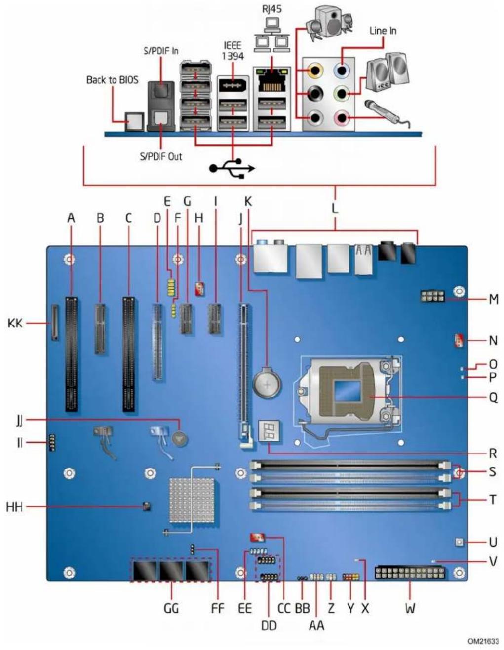
Figure 1 shows the approximate location of the major components on Intel Desktop Board DP55WG.
text_image
S/PDIF In Back to BIOS IEEE 1394 RJ45 Line In S/PDIF Out A B C D E F G H I K L KK J II HH GG FF EE CC BB Z Y X W M N O P Q R S T U V OM21633Figure 1. Intel Desktop Board DP55WG Components
Table 2. Intel Desktop Board DP55WG Components
| Label | Description |
| A PCI bus connector | |
| B PCI Express 2.0 x4 connector (x4 electrical; x16 compatible) | |
| C PCI bus connector | |
| D PCI Express 2.0 x8 connector (x8 electrical; x16 compatible) | |
| E Front panel audio header | |
| F | S/PDIF header |
| G PCI Express 2.0 x1 connector | |
| H Rear chassis fan header | |
| I PCI Express 2.0 x1 connector | |
| J PCI Express 2.0 x16 connector (x8/x16 electrical) | |
| K | Battery |
| L Back panel connectors | |
| M 12 V processor core voltage connector (2 x 4 pin) | |
| N Processor fan header | |
| O | Processor LED |
| P Voltage regulator LED | |
| Q Processor socket | |
| R POST code LED display | |
| S DDR3 Channel A, DIMM 0 and DIMM 1 sockets | |
| T DDR3 Channel B, DIMM 0 and DIMM 1 sockets | |
| U Onboard power button | |
| V Standby power indicator LED | |
| W Main power connector (2 x 12 pin) | |
| X SATA drive activity LED | |
| Y Front panel header | |
| Z Back panel CIR transmitter (output) header | |
| AA | Front panel CIR receiver (input) header |
| BB | Alternate front panel power LED header |
| CC | Front chassis fan header |
| DD | USB 2.0 headers (2) |
| EE | IEEE 1394a header |
| FF | BIOS configuration jumper block |
| GG | Serial ATA connectors |
| HH | Chassis intrusion header |
| II USB 2.0 header | |
| JJ | Speaker |
| KK | Auxiliary PCI Express graphics power connector (SATA-style) |
Online Support
For more information on Intel Desktop Board DP55WG consult the following online resources:
• Intel Desktop Board DP55WG
http://www.intel.com/products/motherboard/DP55WG/index.htm
- Desktop Board Support
http://support.intel.com/support/motherboards/desktop/DP55WG
• Available configurations for Intel Desktop Board DP55WG
http://www.intel.com/products/motherboard/DP55WG/index.htm
• Supported processors
http://processormatch.intel.com
- Chipset information
http://www.intel.com/products/desktop/chipsets/index.htm
• BIOS and driver updates
http://downloadcenter.intel.com/
• Integration information
http://www.intel.com/support/go/buildit
Processor

CAUTION
Failure to use an appropriate power supply and/or not connecting the 12 V (2 x 4 pin) power connector to the Desktop Board may result in damage to the board, or the system may not function properly.
Intel Desktop Board DP55WG supports an Intel processor in the LGA1156 package. Processors are not included with the Desktop Board and must be purchased separately. The processor connects to the Desktop Board through the LGA1156 socket.
For information on supported processors for Intel Desktop Board DP55WG, go to http://processormatch.intel.com.
Main Memory

NOTE
To be fully compliant with all applicable Intel ^® SDRAM memory specifications, the board should be populated with DIMMs that support the Serial Presence Detect (SPD) data structure. If your memory modules do not support SPD, you will see a notification to this effect on the screen at power up. The BIOS will attempt to configure the memory controller for normal operation.
The Desktop Board supports the following memory and interface:
- Four 240-pin Double Data Rate 3 (DDR3) SDRAM Dual Inline Memory Module (DIMM) connectors with gold-plated contacts arranged in two channels
• 1600+/1333/1066 MHz DDR3 SDRAM Memory Modules

NOTE
DDR3 1600 or higher memory support on this desktop board requires compatible XMP-enabled memory or advanced knowledge of BIOS and manual memory tuning. Individual results may vary.
• Support for single- and dual-channel memory interleaving
- Unbuffered, non-registered single- or double-sided DIMMs with a voltage rating of 1.65 V or less

NOTE
Using a DIMM with a voltage rating higher than 1.65 V may damage the processor.
• Non-ECC DDR3 memory
- Serial Presence Detect (SPD) memory only
- Up to 16 GB maximum total system memory

NOTE
32-bit operating systems are limited to a maximum of 4 GB of memory. These operating systems will report less than 4 GB because of the memory used by add-in graphics cards and other system resources.
Intel® P55 Express Chipset
The Intel P55 Express Chipset consists of the Intel P55 Express Platform Controller Hub (PCH). The PCH is the centralized controller for the board's I/O paths.
Audio Subsystem
The onboard audio subsystem consists of the following components:
- Intel ^ P55 PCH
• Realtek ALC889 codec
The subsystem has the following headers and connectors:
- Back panel audio connectors, including S/PDIF in and out optical ports
- High Definition Audio front panel header that provides mic in and line out signals for front panel audio connectors
• An onboard S/PDIF header
The audio subsystem supports the following features:
• Dolby* Home Theater certification
• A signal-to-noise (S/N) ratio of 95 dB
- Independent multi-streaming 8-channel (7.1) audio (using the back panel audio connectors) and 2-channel audio (using the High Definition Audio front panel header)
LAN Subsystem
The LAN subsystem includes:
- Intel PCH
• Intel 82578DM Gigabit (10/100/1000 Mb/s) Ethernet LAN controller - RJ-45 LAN connector with integrated status LEDs
The subsystem features:
• CSMA/CD protocol engine
• LAN connect interface between PCH and the LAN controller
- PCI bus power management
Two LEDs are built into the RJ-45 LAN connector located on the back panel (see Figure 2). These LEDs indicate the status of the LAN as shown in Table 3.

text_image
A B OM21634Figure 2. LAN Connector LEDs
Table 3. LAN Connector LEDs
| LED LED Color LED State | Indicates | ||
| A Off LAN linkGreen not established | |||
| On LAN link is established | |||
| Blinking | LAN activity | ||
| B | N/A Off 10 Mb/s data rate | ||
| Green On 100 Mb/s data rate | |||
| Yellow On 1000 Mb/s data rate | |||
is
USB 2.0 Support
The Desktop Board provides 14 USB 2.0 ports (eight ports routed to back panel connectors and six ports routed to three onboard headers). USB 2.0 ports are backward compatible with USB 1.1 devices. USB 1.1 devices will function normally at USB 1.1 speeds.
USB 2.0 support requires both an operating system and drivers that fully support USB 2.0 transfer rates. Disabling Hi-Speed USB in the BIOS reverts all USB 2.0 ports to USB 1.1 operation. This may be required to accommodate operating systems that do not support USB 2.0.
Serial ATA Support
Intel Desktop Board DP55WG supports six onboard 3.0 Gb/s Serial ATA (SATA) channels via the PCH.
The Desktop Board includes a SATA drive activity indicator (a blue LED) shown in Figure 3.

natural_image
Top-down view of a computer motherboard with CPU socket and RAM slots (no text or symbols visible)Figure 3. SATA Drive Activity LED
The six onboard SATA channels support the following Intel Matrix Storage Technology RAID (Redundant Array of Independent Drives) levels:
• RAID 0 - data striping
• RAID 1 - data mirroring
- RAID 0+1 (or RAID 10) - data striping and data mirroring
• RAID 5 - distributed parity

NOTE
In order to use supported onboard RAID features, you must first enable RAID in the BIOS. Also, during Microsoft Windows XP installation, you must press the F6 key to install the RAID drivers. Refer to your Microsoft Windows XP documentation for more information about installing drivers during installation. Both Microsoft Windows Vista and Microsoft Windows 7 include the necessary RAID drivers for both AHCI and RAID without the need to install separate RAID drivers using the F6 key.
Legacy I/O
Intel Desktop Board DP55WG includes an I/O controller that provides the following legacy I/O features:
• Consumer Infrared (CIR) support
- Low pin count (LPC) interface
• Intelligent power management, including a programmable wake up event interface
• PCI power management support
Expandability
Intel Desktop Board DP55WG provides the following expansion capability:
• One PCI Express 2.0 x16 port (x8/x16 electrical)
• One PCI Express 2.0 x8 port (x8 electrical; x16 compatible)
• One PCI Express 2.0 x4 port (x4 electrical; x16 compatible)
- Two PCI Express 2.0 x1 ports
- Two PCI bus connectors
BIOS
The BIOS provides the Power-On Self-Test (POST), the BIOS Setup program, and the PCI/PCI Express and SATA auto-configuration utilities. The BIOS is stored in a Serial Peripheral Interface (SPI) Flash device.
The BIOS can be updated by following the instructions in Chapter 3 starting on page 65.
Serial ATA Auto Configuration
If you install a Serial ATA device (such as a hard drive) in your computer, the auto-configuration utility in the BIOS automatically detects and configures the device for your computer. You do not need to run the BIOS Setup program after installing a Serial ATA device. You can override the auto-configuration options by specifying manual configuration in the BIOS Setup program.
PCI Express\* Auto Configuration
If you install a PCI Express add-in card in your computer, the PCI Express auto-configuration utility in the BIOS automatically detects and configures the resources (IRQs, DMA channels, and I/O space) for that add-in card. You do not need to run the BIOS Setup program after you install a PCI Express add-in card.
Security Passwords
The BIOS includes security features that restrict whether the BIOS Setup program can be accessed and who can boot the computer. A supervisor password and a user password can be set for the BIOS Setup and for booting the computer, with the following restrictions:
- The supervisor password gives unrestricted access to view and change all Setup options. If only the supervisor password is set, pressing
at the password prompt of Setup gives the user restricted access to Setup. - If both the supervisor and user passwords are set, you must enter either the supervisor password or the user password to access Setup. Setup options are then available for viewing and changing depending on whether the supervisor or user password was entered.
- Setting a user password restricts who can boot the computer. The password prompt is displayed before the computer is booted. If only the supervisor password is set, the computer boots without asking for a password. If both passwords are set, you can enter either password to boot the computer.
Related Links:
For instructions on resetting the password, go to "Clearing Passwords" on page 57.
Hardware Management
The hardware management features of Intel Desktop Board DP55WG enable the board to be compatible with the Wired for Management (WfM) specification. The board has several hardware management features including the following:
• Fan speed monitoring and control
• Thermal and voltage monitoring
- Chassis intrusion detection
Hardware Monitoring and Fan Speed Control
The features of the hardware monitoring and fan speed control include:
- Monitoring of power supply voltages to detect levels above and below acceptable values
- Intel ^ Precision Cooling Technology fan speed control, delivering acoustically-optimized thermal management
- A thermal sensor in the processor
- Thermally monitored closed-loop fan control, for all onboard fans, that can adjust fan speed
Intel® Precision Cooling Technology
Intel Precision Cooling Technology automatically adjusts processor fan speed based on the processor temperature and adjusts chassis fan speeds based on the internal system temperature.
Chassis Intrusion
The board supports a chassis security feature that detects if the chassis cover has been removed. The security feature uses a mechanical switch on the chassis that can be connected to the chassis intrusion header on the Desktop Board. See Figure 27 for the location of the chassis intrusion header.
Power Management
Power management is implemented at several levels, including software support through the Advanced Configuration and Power Interface (ACPI) and the following hardware support:
• Power connectors
- Fan headers
• LAN wake capabilities
- Instantly Available PC technology (Suspend to RAM)
• +5 V standby power indicator LED
- Wake from USB
• Power Management Event signal (PME#) wakeup support
- WAKE# signal wake-up support
- Wake from Consumer IR
Software Support
ACPI
ACPI gives the operating system direct control over the power management and Plug and Play functions of a computer. The use of ACPI with the Desktop Board requires an operating system that provides full ACPI support.
Hardware Support
Power Connectors
ATX12V-compliant power supplies can turn off the computer power through system control. When an ACPI-enabled computer receives the correct command, the power supply removes all non-standby voltages.
When resuming from an AC power failure, the computer returns to the power state it was in before power was interrupted (either on or off). The computer's response can be set by using the Last Power State feature in the BIOS Setup program's Boot menu.
The Desktop Board has three power connectors. See Figure 30 on page 55 for the location of the power connectors.
Fan Headers
The function/operation of the fans is as follows:
• The fans are on when the computer is in the ACPI S0 state.
• The fans are off when the computer is in the ACPI S3, S4, or S5 state.
- Each fan header is wired to a tachometer input of the hardware monitoring and control device.
- All fan headers support closed-loop fan control that can adjust the fan speed or switch the fan on or off as needed.
- All fan headers have a +12 V DC connection.
The Desktop Board has a 4-pin processor fan header and two 4-pin chassis fan headers.
LAN Wake Capabilities

CAUTION
For LAN wake capabilities, the 5 V standby line for the power supply must be capable of delivering adequate +5 V standby current. Failure to provide adequate standby current when using this feature can damage the power supply.
LAN wakeup capabilities enable remote wake-up of the computer through a network. The LAN subsystem monitors network traffic and upon detecting a Magic Packet* frame, it asserts a wake-up signal that powers up the computer.
Instantly Available PC Technology

CAUTIONS
For Instantly Available PC technology, the 5 V standby line for the power supply must be capable of delivering adequate +5 V standby current. Failure to provide adequate standby current when using this feature can damage the power supply and/or effect ACPI S3 sleep state functionality.
Power supplies used with this Desktop Board must be able to provide enough standby current to support the standard Instantly Available (ACPI S3 sleep state) configuration. If the standby current necessary to support multiple wake events from the PCI and/or USB buses exceeds power supply capacity, the Desktop Board may lose register settings stored in memory.
Instantly Available PC technology enables the board to enter the ACPI S3 (Suspend-to-RAM) sleep state. While in the S3 sleep state, the computer will appear to be off. If the computer has a dual-colored power LED on the front panel, the sleep state is indicated by the LED turning amber. When signaled by a wake-up device or event, the computer quickly returns to its last known awake state.
The Desktop Board supports the PCI Bus Power Management Interface Specification. Add-in cards that support this specification can participate in power management and can be used to wake the computer.
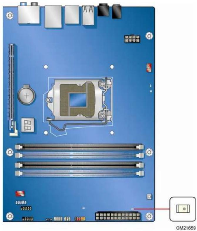
+5 V Standby Power Indicator

CAUTION
If the AC power has been switched off and the standby power indicator is still lit, disconnect the power cord before installing or removing any devices connected to the board. Failure to do so could damage the board and any attached devices.
The Desktop Board's standby power indicator, shown in Figure 4, is lit when there is standby power still present on the board even when the computer appears to be off. For example, when this green LED is lit, standby power is still present at the memory module sockets and the PCI bus connectors.
natural_image
Top-down view of a computer motherboard with visible components and connectors (no text or symbols)Figure 4. Location of the Standby Power Indicator
For more information on standby current requirements for the Desktop Board, refer to the Technical Product Specification at http://support.intel.com/support/motherboards/desktop/.
Wake from USB

NOTE
Wake from USB requires the use of a USB peripheral that supports Wake from USB and an operating system that supports Wake from USB.
USB bus activity wakes the computer from an ACPI S1 or S3 state.
PME# Signal Wake-up Support
When the PME# signal on the PCI bus is asserted, the computer wakes from an ACPI S1, S3, S4, or S5 state.
WAKE# Signal Wake-up Support
When the WAKE# signal on the PCI Express bus is asserted, the computer wakes from an ACPI S1, S3, S4, or S5 state.
Wake from Consumer IR
Consumer IR device activity wakes the computer from an ACPI S3, S4, or S5 state.
ENERGY STAR\*, e-Standby, and EuP Compliance
The US Department of Energy and the US Environmental Protection Agency have continually revised the ENERGY STAR requirements. Intel has worked directly with these two governmental agencies in the definition of the new requirements. This Desktop Board meets the ENERGY STAR Program for Computers: Version 5.0 Category D requirements.
For information about ENERGY STAR requirements and recommended configurations, go to http://www.intel.com/go/energystar.
The Desktop Board also meets the following international requirements:
• Republic of Korea e-Standby program
• European Union Energy using Products (EuP) directive
Onboard Power Button

CAUTION
Electrostatic discharge (ESD) can damage components. Perform the procedure described in this section only at an ESD workstation using an antistatic wrist strap and a conductive foam pad. If such a station is not available, you can provide some ESD protection by wearing an antistatic wrist strap and attaching it to a metal part of the computer chassis.
The power button on the Desktop Board (see Figure 5) can be used to turn the computer on or off. The button duplicates the function of the front panel power button. To turn off the computer using the onboard power button, press it for three seconds.

natural_image
Top-down view of a computer motherboard with visible CPU socket, RAM slots, and connectors (no text or symbols)Figure 5. Onboard Power Button
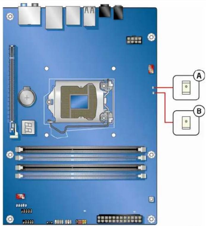
Processor and Voltage Regulator LEDs
The Desktop Board contains two red LEDs (see Figure 6) that indicate the status of the board's voltage regulation circuitry and the processor:
- The Processor LED (Figure 6, A) indicates an elevated temperature on the processor that could affect performance.
- The Voltage Regulator LED (Figure 6, B) indicates an elevated temperature in the processor voltage regulator circuit that could affect performance.
text_image
A BOM21661
Figure 6. Location of the Processor and Voltage Regulator LEDs
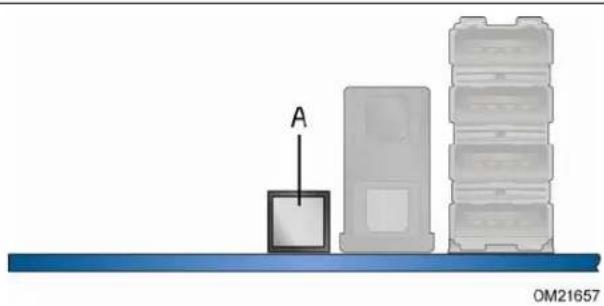
Back to BIOS Button
The Back to BIOS button (Figure 7, A) duplicates the functionality of the BIOS configuration jumper (see Setting the BIOS Configuration Jumper on page 56) with the following exceptions:
- It can only be used to force the board to power on to the BIOS Maintenance Menu using default values.
- It cannot be used to override passwords set in the BIOS.
- It cannot be used to invoke BIOS recovery mode.
The button glows red when it is activated.

NOTE
Using the Back to BIOS button does not set the board to the factory BIOS defaults. To restore settings to the factory defaults, use the
natural_image
Diagram showing a device labeled 'A' pointing upward toward stacked storage units on a blue base (no text or symbols beyond label)Figure 7. Location of the Back to BIOS Button
Speaker
A speaker is mounted on the Desktop Board. The speaker provides audible error code (beep code) information during the Power-On Self-Test (POST). Refer to Appendix A for a description of the board's beep codes.
Battery
A battery on the Desktop Board keeps the values in CMOS RAM and the clock current when the computer is turned off. Go to page 58 for instructions on how to replace the battery.
Real-Time Clock
The Desktop Board has a time-of-day clock and 100-year calendar. The battery on the Desktop Board keeps the clock current when the computer is turned off.
2 Installing and Replacing Desktop Board Components
This chapter tells you how to:
• Install the I/O shield
• Install and remove the Desktop Board
• Install and remove a processor
• Install and remove memory
• Install and remove a PCI Express x16 graphics card
- Connect the Serial ATA cables
- Connect to the internal headers
- Connect to the audio system
- Connect chassis fan and power supply cables
- Set the BIOS configuration jumper
- Clear passwords
- Replace the battery
Before You Begin

CAUTIONS
The procedures in this chapter assume familiarity with the general terminology associated with personal computers and with the safety practices and regulatory compliance required for using and modifying electronic equipment.
Disconnect the computer from its power source and from any telecommunications links, networks, or modems before performing any of the procedures described in this chapter. Failure to disconnect power, telecommunications links, networks, or modems before you open the computer or perform any procedures can result in personal injury or equipment damage. Some circuitry on the board can continue to operate even though the front panel power button is off.
Follow these guidelines before you begin:
• Always follow the steps in each procedure in the correct order.
- Set up a log to record information about your computer, such as model, serial numbers, installed options, and configuration information.
- Electrostatic discharge (ESD) can damage components. Perform the procedures described in this chapter only at an ESD workstation using an antistatic wrist strap and a conductive foam pad. If such a station is not available, you can provide some ESD protection by wearing an antistatic wrist strap and attaching it to a metal part of the computer chassis.
Installation Precautions
When you install and test the Intel Desktop Board, observe all warnings and cautions in the installation instructions.
To avoid injury, be careful of:
- Sharp pins on connectors
- Sharp pins on printed circuit assemblies
- Rough edges and sharp corners on the chassis
• Hot components (such as processors, voltage regulators, and heat sinks) - Damage to wires that could cause a short circuit
Observe all warnings and cautions that instruct you to refer computer servicing to qualified technical personnel.
Prevent Power Supply Overload
Do not overload the power supply output. To avoid overloading the power supply, make sure that the calculated total current loads of all the modules within the computer is less than the output current rating of each of the power supplies output circuits.
Observe Safety and Regulatory Requirements
Read and follow the instructions in this section and the instructions supplied with the chassis and associated modules. If you do not follow these instructions and the instructions provided by the chassis and module suppliers, you increase your safety risk and the possibility of noncompliance with regional laws and regulations. If the instructions for the chassis are inconsistent with these instructions or the instructions for associated modules, contact the supplier to find out how you can ensure that your computer meets safety and regulatory requirements.
For information about the Desktop Board's regulatory compliance, refer to Appendix B.
Installing the I/O Shield
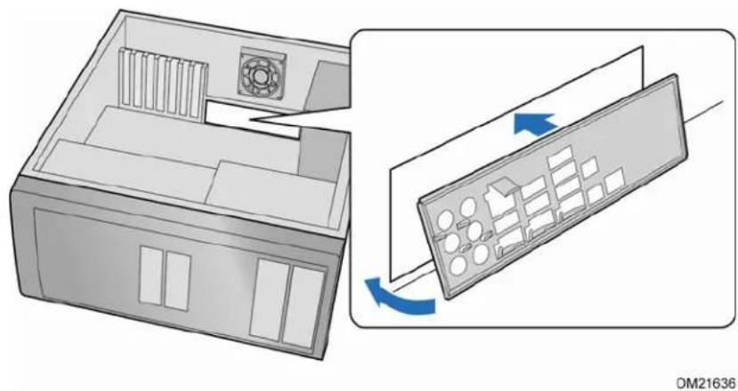
The Desktop Board comes with an I/O shield. When installed in the chassis, the shield blocks radio frequency transmissions, protects internal components from dust and foreign objects, and promotes correct airflow within the chassis.
Install the I/O shield before installing the Desktop Board in the chassis. Place the shield inside the chassis as shown in Figure 8. Press the shield into place so that it fits tightly and securely. If the shield does not fit, obtain a properly sized shield from the chassis supplier.
natural_image
Diagram showing a computer case with a fan and internal components, and a close-up of the internal keyboard with blue arrows indicating rotation (no text or symbols)Figure 8. Installing the I/O Shield
Installing and Removing the Desktop Board

CAUTION
Only qualified technical personnel should perform this procedure. Disconnect the computer from its power source before performing the procedures described here. Failure to disconnect the power before you open the computer can result in personal injury or equipment damage.
Refer to your chassis manual for instructions on installing and removing the Desktop Board.
Figure 9 shows the location of the mounting screw holes for Intel Desktop Board DP55WG.
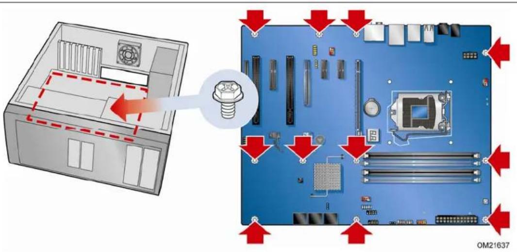
text_image
Diagram showing computer motherboard components with red arrows indicating assembly or disassembly, including a screw and CPU socket.Figure 9. Intel Desktop Board DP55WG Mounting Screw Hole Locations
Installing and Removing a Processor
Instructions on how to install the processor on the Desktop Board are given below.
Installing a Processor

CAUTION
Before installing or removing a processor, make sure the AC power has been removed by unplugging the power cord from the computer; the standby power LED should not be lit (see Figure 4 on page 23). Failure to do so could damage the processor and the board.
To install a processor, follow these instructions:
- Observe the precautions in "Before You Begin" on page 29.
- Un latch the socket lever by pushing the lever down and away from the socket (Figure 10, A and B).
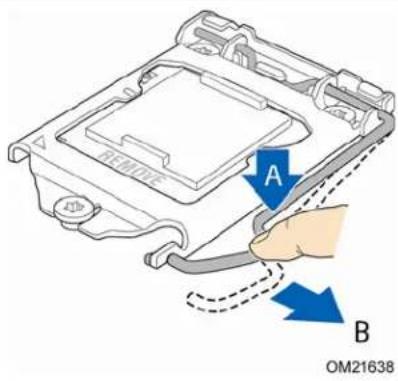
text_image
A B OM21638Figure 10. Unlatch the Socket Lever
- Rotate the socket lever to lift the load plate away from the socket (Figure 11, A). Make sure that the load plate is in the fully open position (Figure 11, B) while being careful not to damage adjacent components.
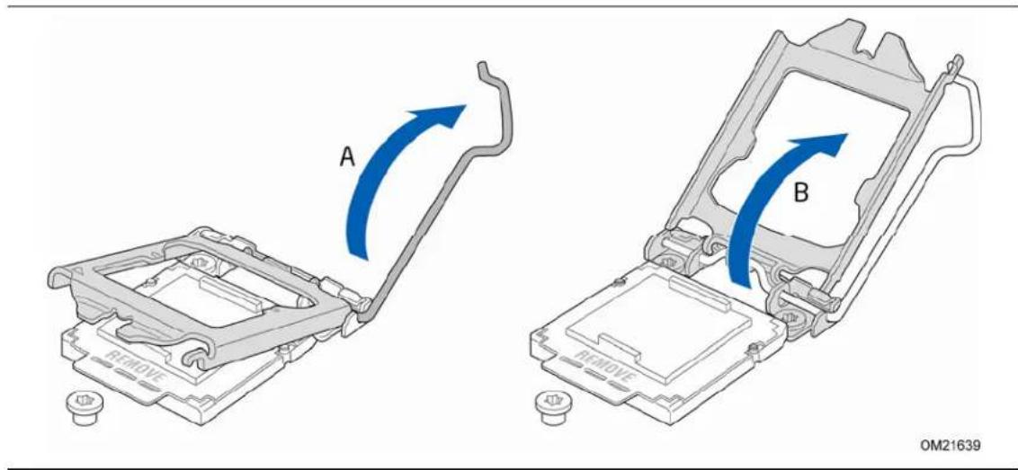
text_image
A B OM21639Figure 11. Lift the Load Plate
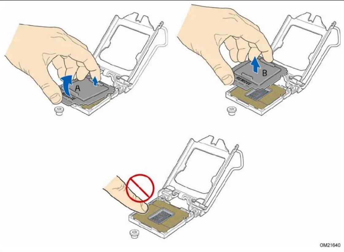
- Remove the protective socket cover from the socket by placing your thumb against the front edge of the cover and resting your index finger on the rear grip (Figure 12, A). Lift the front edge of the socket to disengage the cover from the socket and lift the cover up and away from the socket (Figure 12, B). Do not touch the socket contacts.

NOTE
Do not discard the socket cover; save it for possible future use. Always replace the socket cover if you remove the processor from the socket.
text_image
A B REMOVE OM21640Figure 12. Remove the Socket Cover
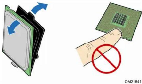
- Remove the processor from its protective cover. Hold the processor only at the edges, being careful not to touch the bottom of the processor (see Figure 13).

NOTE
Do not discard the processor cover. Always replace the processor cover if the you remove the processor from the socket.
text_image
OM21641Figure 13. Remove the Processor from the Protective Cover
- Hold the processor with your thumb and index finger oriented as shown in Figure 14 to align your fingers with the socket finger cutouts. Make sure that the processor Pin 1 indicator (gold triangle) is aligned with the Pin 1 chamfer on the socket (Figure 14, B) and that the notches on the processor align with the posts on the socket (Figure 14, C). Lower the processor straight down without tilting or sliding it in the socket (Figure 14, A).

text_image
A B C OM21642Figure 14. Install the Processor
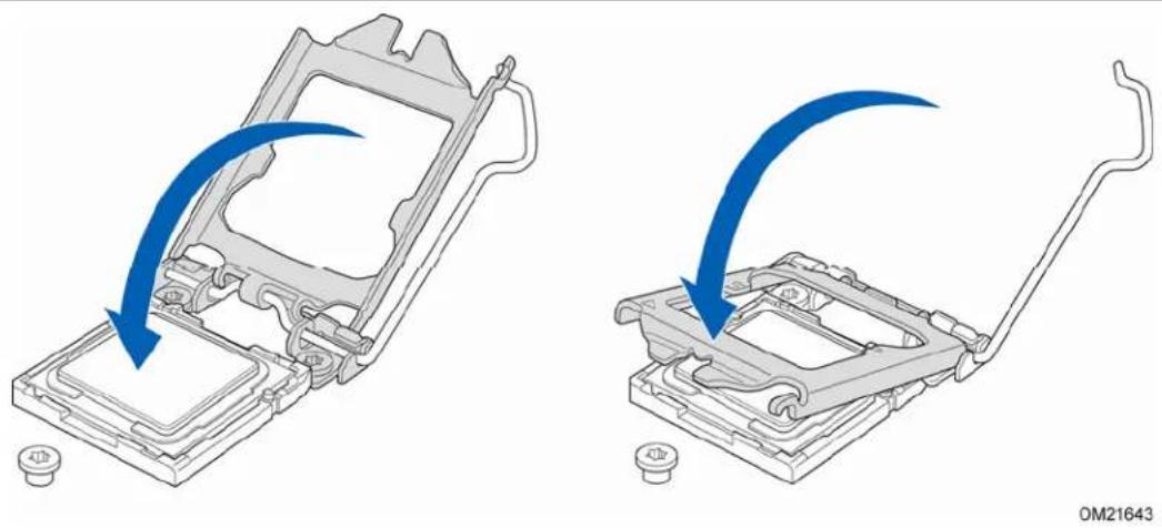
- Lower the load plate over the processor while leaving the socket lever in the open position (Figure 15).
natural_image
Two technical diagrams showing a mechanical assembly with blue arrows indicating direction of motion, no text or symbols present.Figure 15. Lower the Load Plate
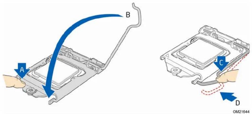
- Lower the socket lever (Figure 16, B) while making sure that the front edge of the load plate slides under the shoulder screw cap as the lever is lowered (Figure 16, A). Latch the socket lever under load plate tab (Figure 16, C, D).
text_image
A B C D OM21644Figure 16. Secure the Load Plate in Place
Installing the Processor Fan Heat Sink
Intel Desktop Board DP55WG has mounting holes for a processor fan heat sink. For instructions on how to attach the processor fan heat sink to the Desktop Board, refer to the boxed processor manual or boxed thermal solution manual.
Connecting the Processor Fan Heat Sink Cable
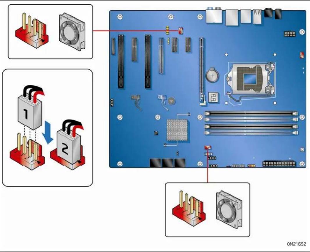
Connect the processor fan heat sink power cable to the 4-pin processor fan header (see Figure 17). A fan with a 4-pin connector as shown in Figure 17 is recommended.

text_image
Technical diagram showing computer motherboard and CPU socket installation with labeled components and wiring instructions0M21656
Figure 17. Connecting the Processor Fan Heat Sink Power Cable to the Processor Fan Header
Removing the Processor
For instructions on how to remove the processor fan heat sink and processor, refer to the processor installation manual.
Installing and Removing System Memory
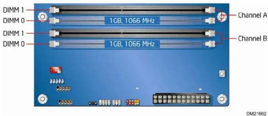
Desktop board DP55WG has four 240-pin DDR3 DIMM sockets arranged as DIMM 0 and DIMM 1 in both Channel A and Channel B.

NOTE
The Intel P55 Express Chipset requires memory to be installed in the Channel A, DIMM 0 slot.
Guidelines for Dual Channel Memory Configuration
Before installing DIMMs, read and follow these guidelines for dual channel memory configuration.
Two or Four DIMMs
Install a matched pair of DIMMs equal in speed and size (see Figure 18) in DIMM 0 (blue) of channels A and B.
text_image
DIMM 1 DIMM 0 DIMM 1 DIMM 0 1GB, 1066 MHz 1GB, 1066 MHz Channel A Channel B OM21662Figure 18. Example Dual Channel Memory Configuration with Two DIMMs
If additional memory is to be used, install another matched pair of DIMMs in DIMM 1 (black) in channels A and B (see Figure 19).

text_image
DIMM 1 DIMM 0 DIMM 1 DIMM 0 2 GB, 1066 MHz 1 GB, 1066 MHz 2 GB, 1066 MHz 1 GB, 1066 MHz Channel A Channel B OM21663Figure 19. Example Dual Channel Memory Configuration with Four DIMMs
Three DIMMs
If you want to use three DIMMs in a dual-channel configuration, install a matched pair of DIMMs equal in speed and size in DIMM 0 (blue) and DIMM 1 (black) of channel A. Install a DIMM equal in speed and total size of the DIMMs installed in channel A in either DIMM 0 or DIMM 1 of channel B (see Figure 20).

text_image
DIMM 1 DIMM 0 DIMM 1 DIMM 0 1 GB, 1066 MHz 1 GB, 1066 MHz 2 GB, 1066 MHz Channel A Channel B OM21664Figure 20. Example Dual Channel Memory Configuration with Three DIMMs

NOTE
All other memory configurations will result in single channel memory operation.
Installing DIMMs
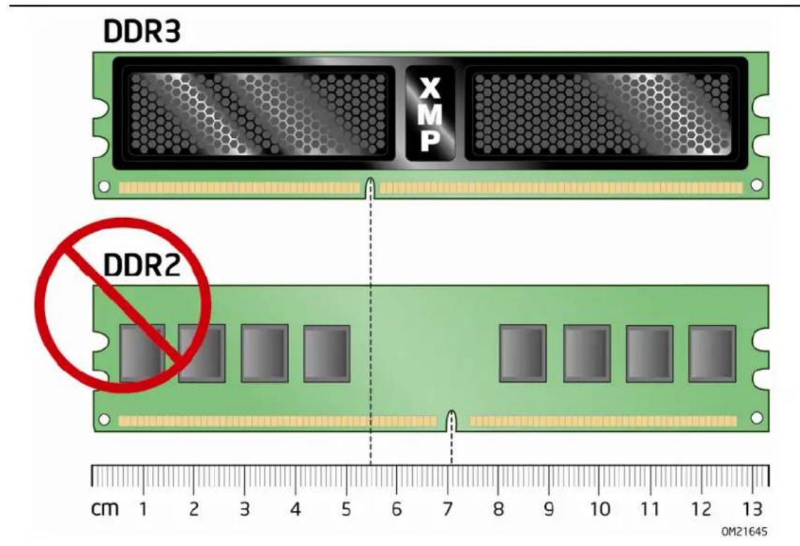
To make sure you have the correct DIMM, place it on the illustration of the DDR3 DIMM in Figure 21. All the notches should match with the DDR3 DIMM.
text_image
DDR3 XMP DDR2 cm 1 2 3 4 5 6 7 8 9 10 11 12 13 0M21645Figure 21. Use DDR3 DIMMs

NOTE
For best memory performance, install memory in the blue DIMM sockets first.
To install a DIMM, follow these steps:
- Observe the precautions in "Before You Begin" on page 29.
- Turn off all peripheral devices connected to the computer. Turn off the computer and disconnect the AC power cord.
- Remove the computer's cover and locate the DIMM sockets (see Figure 22).
text_image
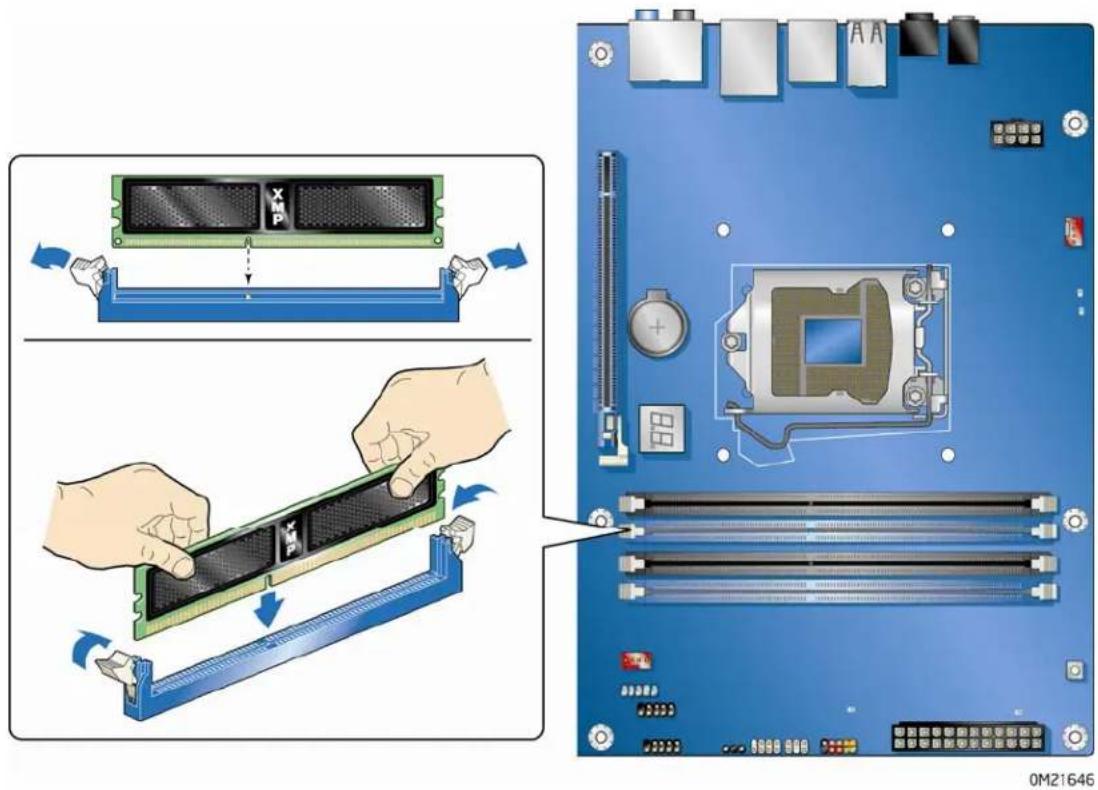
Diagram illustrating the assembly of a computer RAM module into a motherboard, showing component disassembly and assembly steps.Figure 22. Installing a DIMM
- If a full length PCI Express graphics card is installed in the PCI Express x16 connector, remove the card (see Removing a PCI Express x16 Graphics Card on page 44) to gain access to the DIMM sockets.
- Make sure the clips at either end of the DIMM socket(s) are pushed outward to the open position.
- Holding the DIMM by the edges, remove it from its anti-static package.
- Position the DIMM above the socket. Align the small notch at the bottom edge of the DIMM with the keys in the socket (see inset in Figure 22).
- In sert the bottom edge of the DIMM into the socket.
-
When the DIMM is inserted, push down on the top edge of the DIMM until the retaining clips snap into place. Make sure the clips are firmly in place.
-
Reinstall the PCI Express graphics card (see Installing a PCI Express x16 Graphics Card on page 43) if it was removed in Step 4.
- Replace the computer's cover and reconnect the AC power cord.
Removing DIMMs
To remove a DIMM, follow these steps:
- Observe the precautions in "Before You Begin" on page 29.
-
Turn off all peripheral devices connected to the computer. Turn off the computer.
-
Remove the AC power cord from the computer.
-
Remove the computer's cover.
-
If a full length PCI Express graphics card is installed in the PCI Express x16 connector, remove the card (see Removing a PCI Express x16 Graphics Card on page 44) to gain access to the DIMM sockets.
-
Gently spread the retai ning clips at each end of the DIMM socket. The DIMM pops out of the socket.
-
Hold the DIMM by the edges, lift it away from the socket, and store it in an anti-static package.
-
Reinstall the PCI Express graphics card (see Installing a PCI Express x16 Graphics Card on page 43) if it was removed in Step 5 and reinstall and reconnect any parts you removed or disconnected to reach the DIMM sockets.
-
Replace the computer's cover and reconnect the AC power cord.
Installing and Removing PCI Express x16 Graphics Cards
Installing a PCI Express x16 Graphics Card

CAUTION
Before installing the PCI Express x16 graphics card, make sure the tabs on the DIMM sockets are in the upright position (closed); otherwise, they may be damaged by the PCI Express card.

CAUTION
When installing a PCI Express card, ensure that the card is fully seated in the PCI Express connector before you power on the system. If the card is not fully seated in the connector, an electrical short may result across the connector pins. Depending on the over-current protection of the power supply, certain Desktop Board components and/or traces may be damaged.
Follow these instructions to install a PCI Express x16 graphics card:
- Observe the precautions in "Before You Begin" on page 29.
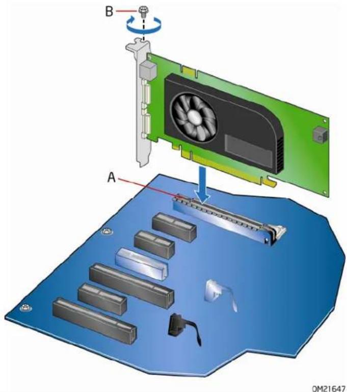
- Place the card in the PCI Express x16 connector (Figure 23, A) and press down on the card until it is completely seated in the connector and the card retention notch on the card snaps into place around the retention mechanism pin on the connector.
- Secure the card's metal bracket to the chassis back panel with a screw (Figure 23, B).
- Con nect the monitor cable to the graphics card according to the manufacturer's instructions.
text_image
B A OM21647Figure 23. Installing a PCI Express x16 Graphics Card
Removing a PCI Express x16 Graphics Card
Follow these instructions to remove a PCI Express x16 graphics card from a connector:
- Observe the precautions in "Before You Begin" on page 29.
- Remove the screw (Figure 24, A) that secures the card's metal bracket to the chassis back panel.
- Push the card ejector lever down using the tip of a pencil or similar tool (Figure 24, B) in the notch. This will release the card from the connector (C).
- Pull the card straight up to remove it.
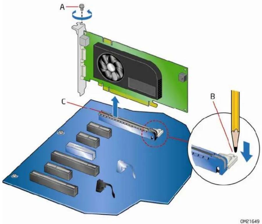
text_image
A C B OM21649Figure 24. Removing a PCI Express x16 Graphics Card
Installing Linked PCI Express Graphics Cards
The Desktop Board supports technology that allows you to install linked PCI Express graphics cards such as NVIDIA* SLI* (Scalable Link Interface) cards. Make sure you use two identical SLI-ready graphics cards that are NVIDIA certified and the latest graphics driver. You can use the connector included with the Desktop Board to connect the two graphics cards together. Visit the NVIDIA zone website (http://nzone.com) for more information.
To install two linked PCI Express graphics cards:
- Observe the precautions in "Before You Begin" on page 29.
- In stall the first card in the PCI Express x16 connector as described in "Installing a PCI Express x16 Graphics Card" on page 43.
- Place the second card in the PCI Express x8 connector (Figure 25, A) and press down on the card until it is completely seated in the connector and the card retention notch on the card snaps into place around the retention mechanism pin on the connector.
- Secure the card's metal bracket to the chassis back panel with a screw (Figure 25, B).
-
Con nect the two cards together with the SLI bridge (Figure 25, C) as shown.
-
Connect the monitor cable to the graphics card according to the manufacturer's instructions.
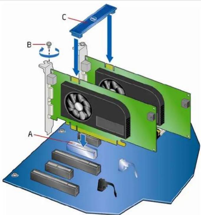
text_image
Diagram of a computer motherboard with labeled components A, B, C and directional arrows indicating assembly or movement.0M21648
Figure 25. Installing Linked PCI Express Graphics Cards
For more complete installation and configuration information refer to the documentation supplied by the graphics card manufacturer or visit their website.
Connecting the Serial ATA (SATA) Cables
SATA cables support the Serial ATA protocol. Each cable can be used to connect one internal SATA drive to the Desktop Board. For correct cable function:
- Observe the precautions in "Before You Begin" on page 29.
- Attach one end of the SATA cable to one of the SATA connectors on the board (Figure 26, A) and attach the other end of the cable to the SATA drive (Figure 26, B).

text_image
Diagram showing network connection between a computer board and an Ethernet cable, with labeled components and wiring details.Figure 26. Connecting the Serial ATA Cables
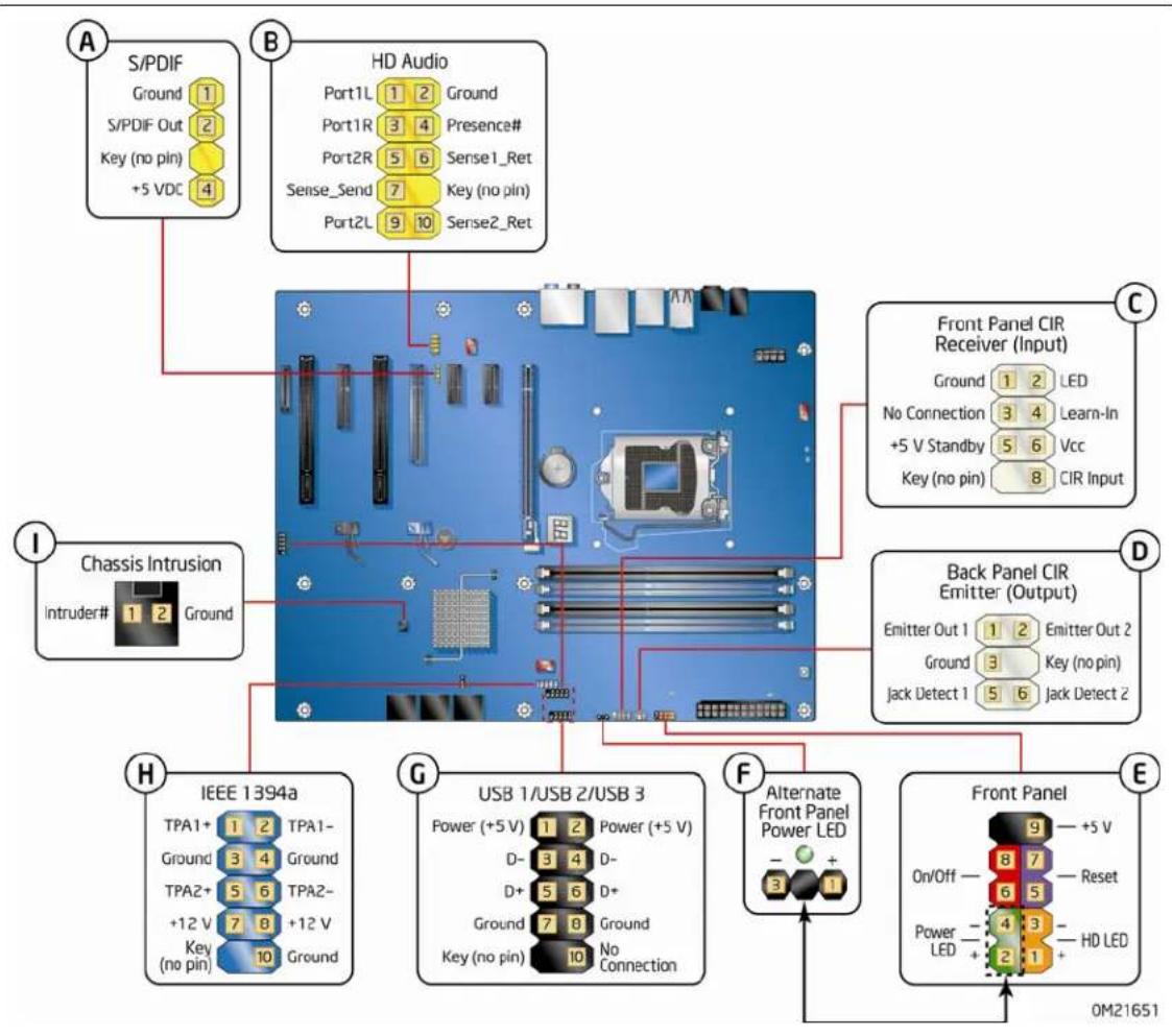
Connecting to the Internal Headers
Before connecting cables to any of the internal headers, observe the precautions in "Before You Begin" on page 29. Figure 27 shows the location of the internal headers and connectors on Intel Desktop Board DP55WG.
flowchart
graph TD
    A["Power (no pin)"] --> B["USB 1/USB 2/USB 3"]
    B --> C["Chassis Intrusion"]
    C --> D["Front Panel CIR Emitter (Output)"]
    D --> E["Front Panel"]
    style A fill:#f9f,stroke:#333
    style B fill:#ccf,stroke:#333
    style C fill:#cfc,stroke:#333
    style D fill:#fcc,stroke:#333
    style E fill:#cff,stroke:#333
Figure 27. Internal Headers
S/PDIF Header
Figure 27, A shows the location of the S/PDIF output header. Table 4 shows the pin assignments and signal names for the S/PDIF connector.
Table 4. S/PDIF Header Signal Names
| Pin | Description |
| 1 | Ground |
| 2 | S/PDIF Out |
| 3 Key | (no pin) |
| 4 | +5 VDC |
Front Panel Intel HD Audio Header
Figure 27, B shows the location of the front panel Intel HD Audio header. Table 5 shows the pin assignments and signal names for the front panel Intel HD Audio header.
Table 5. Front Panel Intel HD Audio Header Signal Names
| Pin | Signal | Name | Pin | Signal | Name |
| 1 PORT 1L 2 GND | |||||
| 3 | PORT | 1R | 4 | PRESENCE# | |
| 5 | PORT | 2R | 6 | SENSE1_RETURN | |
| 7 | SENSE_SEND | 8 | KEY | (no pin) | |
| 9 | PORT | 2L | 10 | SENSE2_RETURN | |
Consumer IR (CIR) Headers
The Desktop Board has two CIR headers: the input or receiver header (Figure 27, C) and the output or emitter header (Figure 27, D). The receiver header consists of a filtered translated infrared input compliant with Microsoft CIR specifications and a "learning" infrared input. The learning input is a high-pass input which the computer can use to "learn" to speak the infrared communication language of other user remotes. The emitter header consists of two output ports which the computer can use to emulate "learned" infrared commands in order to control external electronic hardware.

NOTE
The Consumer IR option must be enabled in the system BIOS before it can function. Press
Table 6 shows the pin assignments and signal names for the front panel CIR receiver (input) header and Table 7 shows the pin assignments and signal names for the back panel CIR emitter (output) header.
Table 6. Front Panel CIR Receiver (Input) Header Signal Names
| Pin | Signal | Name | Pin | Signal | Name |
| 1 | Ground 2 | LED | |||
| 3 | No Connection | 4 | Learn-In | ||
| 5 | +5 V | Standby 6 Vcc | |||
| 7 | Key (no pin) | 8 CIR Input |
Table 7. Back Panel CIR Header Emitter (Output) Header Signal Names
| Pin | Signal | Name | Pin | Signal | Name |
| 1 | Emitter Out 1 | 2 Emitter Out 2 | |||
| 3 | Ground | 4 | Key | (no pin) | |
| 5 | Jack Detect 1 | 6 Jack Detect 2 | |||
Front Panel Header
Figure 27, E shows the location of the front panel header. Table 8 shows the pin assignments and signal names for the front panel header.
Table 8. Front Panel Header Signal Names
| Pin | Description In/Out | Pin | Description In/Out | ||
| Hard Drive Activity LED | Power LED | ||||
| 1 | Hard disk LED pull-up to +5 V | Out | 2 | Front panel green LED | Out |
| 3 | Hard disk active LED | Out | 4 | Front panel yellow LED | Out |
| Reset Switch | On/Off Switch | ||||
| 5 | Ground | 6 | Power switch | In | |
| 7 | Reset switch | In | 8 | Ground | |
| Power | Not Connected | ||||
| 9 | Power | Out | 10 | No pin | |

NOTE
When connecting individual wires from your chassis front panel to the front panel header, be sure to observe the connection polarity. Positive wires are usually solid color and negative wires are usually white or striped.
Alternate Front Panel Power LED Header
Figure 27, F shows the location of the alternate front panel power LED header. Pins 1 and 3 of this header duplicate the signals on pins 2 and 4 of the front panel header. If your chassis has a three-pin power LED cable, connect it to this header. Table 9 shows the pin assignments for the alternate front panel header.
Table 9. Alternate Front Panel Power LED Header Signal Names
| Pin | Signal | Name | In/Out |
| 1 | Front panel green LED Out | ||
| 2 | No pin | ||
| 3 | Front panel yellow LED Out | ||
USB 2.0 Headers
Figure 27, G shows the location of the USB 2.0 headers. Table 10 shows the pin assignments and signal names for each USB 2.0 header. Each USB header can be used to connect two USB devices.
Table 10. USB 2.0 Header Signal Names
| USB Port A USB Port B | |||
| Pin Signal Name Pin Signal Name | |||
| 1 Power | (+5 V) 2 | Power | (+5 V) |
| 3 | D- | 4 | D- |
| 5 | D+ | 6 | D+ |
| 7 | Ground | 8 | Ground |
| 9 | Key | 10 | No Connection |
Note: USB ports may be assigned as needed.

NOTE
Computer systems that have an unshielded cable attached to a USB port might not meet FCC Class B requirements, even if no device or a low-speed USB device is attached to the cable. Use a shielded cable that meets the requirements for a full-speed USB device.
IEEE 1394a Header
Figure 27, H shows the location of the IEEE 1394a header. Table 11 shows the pin assignments and signal names for the IEEE 1394a header.
Table 11. IEEE 1394a Header Signal Names
| Pin | Signal | Name | Pin | Signal | Name |
| 1 TPA1 | + 2 TPA1- | ||||
| 3 | Ground | 4 Ground | |||
| 5 | TPA2+ | 6 TPA2- | |||
| 7 | +12 | V | 8 | +12 | V |
| 9 Key (no pin) | 10 Ground |
Chassis Intrusion Header
Figure 27, I shows the location of the chassis intrusion header. This header can be connected to a mechanical switch on the chassis to detect if the chassis cover is removed. This switch should be in the open position when the chassis cover is installed and closed when the cover is removed.
Table 12 shows the pin assignments and signal names for the chassis intrusion header.
Table 12. Chassis Intrusion Header Signal Names
| Pin | Description |
| 1 | Intruder# |
| 2 | Ground |
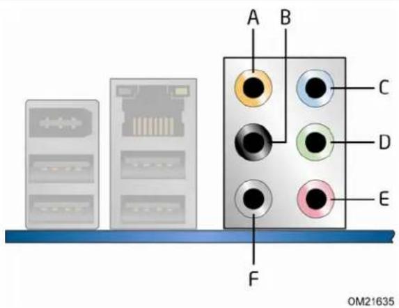
Connecting to the Audio System
After installing the Realtek audio driver from the Intel® Express Installer DVD-ROM, the multi-channel audio feature can be enabled. Figure 28 shows the back panel audio connectors. The connector assignments are shown in the table.
text_image
A B C D E F OM21635Item Description
| A | Center Channel and LFE (Subwoofer) | |
| B | Surround Left and Right | |
| C | Side Surround Left and Right/Line In/Retasking Jack | |
| D | Line | Out |
| E | Mic | In |
| F | Side | Surround |
Figure 28. Back Panel Audio Connectors

NOTE
The back panel line out connector is designed to power either headphones or amplified speakers only. Poor audio quality may occur if passive (non-amplified) speakers are connected to this output.
Connecting Chassis Fan and Power Supply Cables
Connecting Chassis Fan Cables
Connect chassis fan cables to the chassis fan headers on the Desktop Board. Figure 29 shows the location of the chassis fan headers.
text_image
Diagram illustrating the assembly of a computer motherboard with labeled components and directional arrows indicating assembly steps.Figure 29. Location of the Chassis Fan Headers
Connecting Power Supply Cables
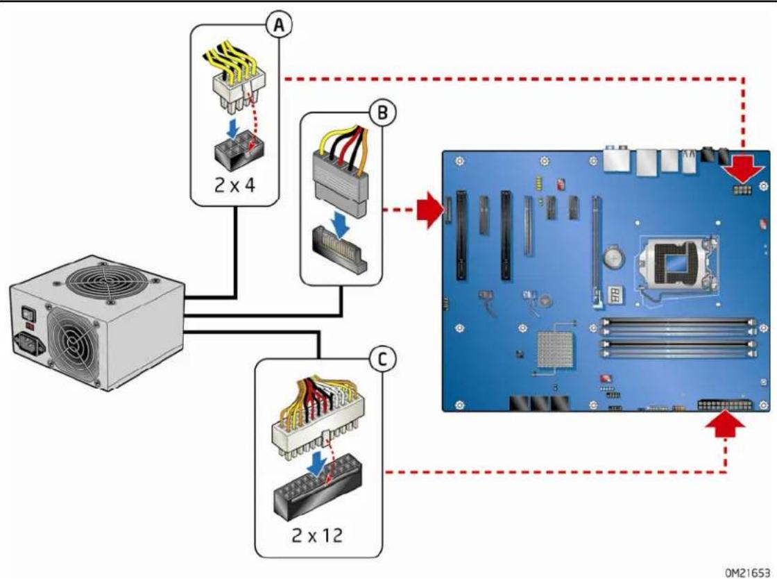
Figure 30 shows the location of the power connectors.

CAUTION
Failure to use an appropriate power supply and/or not connecting the 12 V power connector (Figure 30, A) to the Desktop Board may result in damage to the board or the system may not function properly.
The 2 x 12 pin main power connector (Figure 30, C) is backwards compatible with ATX12V power supplies with 2 x 10 connectors. Use of the SATA-style PCI Express graphics auxiliary power connector (Figure 30, B) is required with ATX12V power supplies when using PCI Express graphics cards that can consume up to 75 W.
flowchart
graph TD
    A["Power Supply"] --> B["2x4 Component"]
    A --> C["2x12 Component"]
    B --> D["Computer Board"]
    C --> D
    D --> E["Status Indicator: Red Arrow"]
    style A fill:#f9f,stroke:#333
    style B fill:#ccf,stroke:#333
    style C fill:#cfc,stroke:#333
    style D fill:#fff,stroke:#333
Figure 30. Connecting Power Supply Cables
- Observe the precautions in "Before You Begin" on page 29.
- Connect the 12 V processor core voltage power supply cable to the 2 x 4 pin connector (Figure 30, A).
- Con nect the main power supply cable to the 2 x 12 pin connector (Figure 30, C).
- If additional power is required for graphics cards, connect the appropriate power supply cable to the SATA-style PCI Express graphics auxiliary power connector.
Setting the BIOS Configuration Jumper

NOTE
Always turn off the power and unplug the power cord from the computer before moving the jumper. Moving the jumper with the power on may result in unreliable computer operation.
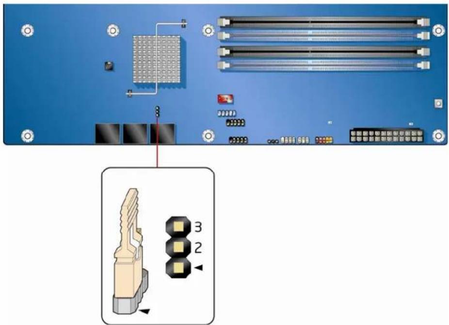
Figure 31 shows the location of the Desktop Board's BIOS configuration jumper block.
text_image
Technical diagram showing a computer motherboard with labeled components and an inset image of a connector pin layout.0M21654
Figure 31. Location of the BIOS Configuration Jumper Block
The three-pin BIOS jumper block enables board configuration to be done in the BIOS Setup program. Table 13 shows the jumper settings for the BIOS Setup program modes.
Table 13. Jumper Settings for the BIOS Setup Program Modes
| Jumper Setting | Mode Description | |
 | Normal (default) (1-2) The BIOS uses the current configuration and passwords for booting. | |
 | Configure (2-3) After the Power-On Self-Test (POST) runs, the BIOS displays the Maintenance Menu. Use this menu to clear passwords. | |
 | Recovery (None) The BIOS recovers data in the event of a failed BIOS update. | |
Clearing Passwords
This procedure assumes that the board is installed in the computer and the configuration jumper block is set to normal mode.
- Observe the precautions in "Before You Begin" on page 29.
- Turn off all peripheral devices connected to the computer. Turn off the computer. Disconnect the computer's power cord from the AC power source (wall outlet or power adapter).
- Remove the computer cover.
- Find the configuration jumper block (see Figure 31).
- Place the jumper on pins 2-3 as shown below.

- Replace the cover, plug in the computer, turn on the computer, and allow it to boot.
-
The computer starts the Setup program. Setup displays the Maintenance menu.
-
Use the arrow keys to select Clear Passwords. Press
and Setup displays a pop-up screen requesting that you confirm clearing the password. Select Yes and press . Setup displays the maintenance menu again. - Press
to save the current values and exit Setup. - Turn off the computer. Disconnect the computer's power cord from the AC power source.
- Remove the computer cover.
- To restore normal operation, place the jumper on pins 1-2 as shown below.
- Replace the cover, plug in the computer, and turn on the computer.
Replacing the Battery
A coin-cell battery (CR2032) powers the real-time clock and CMOS memory. When the computer is not plugged into a wall socket, the battery has an estimated life of three years. When the computer is plugged in, the standby current from the power supply extends the life of the battery. The clock is accurate to ± 13 minutes/year at 25 °C with 3.3 VSB applied.
When the voltage drops below a certain level, the BIOS Setup program settings stored in CMOS RAM (for example, the date and time) might not be accurate. Replace the battery with an equivalent one. Figure 32 on page 63 shows the location of the battery.

CAUTION
Risk of explosion if the battery is replaced with an incorrect type. Batteries should be recycled where possible. Disposal of used batteries must be in accordance with local environmental regulations.

PRÉCAUTION
To replace the battery, follow these steps:
- Observe the precautions in "Before You Begin" (see page 29).
- Turn off all peripheral devices connected to the computer. Disconnect the computer's power cord from the AC power source (wall outlet or power adapter).
- Remove the computer cover.
- Locate the battery on the board (see Figure 32).
- With a medium flat-bladed screwdriver, gently pry the battery free from its connector. Note the orientation of the "+" and "-" on the battery.
- Install the new battery in the connector, orienting the "+" and "-" correctly.
- Replace the computer cover.
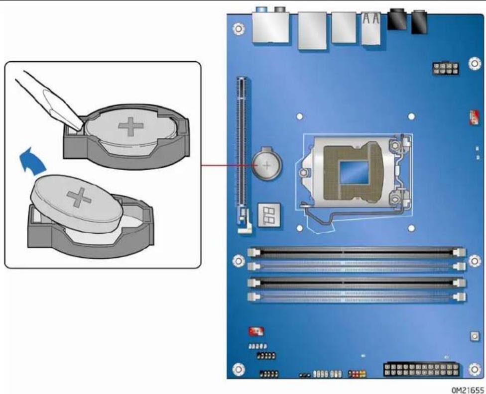
natural_image
Top-down view of a computer motherboard showing CPU socket, RAM slots, and heatsink (no text or symbols)Figure 32. Removing the Battery
Intel Desktop Board DP55WG Product Guide
3 Updating the BIOS
The BIOS Setup program can be used to view and change the BIOS settings for the computer. You can access the BIOS Setup program by pressing the
This chapter tells you how to update the BIOS by either using the Intel Express BIOS Update utility or the Iflash Memory Update utility, and how to recover the BIOS if an update fails.
Updating the BIOS with the Intel® Express BIOS Update Utility
With the Intel Express BIOS Update utility you can update the system BIOS while in the Windows environment. The BIOS file is included in an automated update utility that combines the functionality of the Intel® Flash Memory Update Utility and the ease of use of Windows-based installation wizards.
To update the BIOS with the Intel Express BIOS Update utility:
- Go to the Intel World Wide Web site:
http://support.intel.com/support/motherboards/desktop/ - Navigate to the DP55WG page, click "[view] Latest BIOS updates," and select the Express BIOS Update utility file.
- Download the file to your hard drive. (You can also save this file to a removable USB device. This is useful if you are updating the BIOS for multiple identical systems.)
- Close all other applications. This step is required. Your system will be rebooted at the last Express BIOS Update window.
- Double-click the executable file from the location on your hard drive where it was saved. This runs the update program.
- Follow the instructions provided in the dialog boxes to complete the BIOS update.
Updating the BIOS with the ISO Image BIOS Update File or the Iflash Memory Update Utility
You can use the information in this section to update the BIOS using either the Iflash Memory Update Utility or the ISO Image BIOS update file.
Obtaining the BIOS Update File
You can update to a new version of the BIOS by using the ISO Image BIOS update file (recommended), or Iflash BIOS update file.
The ISO Image BIOS update file is a standardized image of a bootable CD-ROM that can be used to create a bootable CD that will update the BIOS.
The Iflash BIOS update file is a compressed file that contains the files you need to update the BIOS. The Iflash BIOS update file contains:
- New BIOS file (including the Intel ^ Management Engine Firmware Image)
- Intel ^ Integrator Toolkit Configuration File (optional)
• Intel Flash Memory Update Utility
You can obtain either of these files through your computer supplier or by navigating to the Intel Desktop Board DP55WG page on the Intel World Wide Web site at:
http://support.intel.com/support/motherboards/desktop
Navigate to the DP55WG page, click "[view] Latest BIOS updates," and select the ISO Image BIOS Update or Iflash BIOS Update utility file.
Updating the BIOS with the ISO Image BIOS Update File
The ISO Image BIOS update allows for the update of an Intel ^® Desktop Board BIOS to the latest production release regardless of the operating system installed on the computer's hard drive and without the need to remove the BIOS configuration jumper. It requires a blank CD-R, a read/writeable CD drive, and software capable of uncompressing and writing the ISO image file to CD.
The image uses ISOLINUX* bootloader and automatically launches a script to upgrade the BIOS via the Iflash utility.

CAUTION
Do not interrupt the process or the system may not function properly.
Follow these instructions to upgrade the BIOS using the ISO Image BIOS file:
- Download the ISO Image BIOS file.
- Using software capable of uncompressing and writing an ISO image file to CD, burn the data to a blank CD.

NOTE
Copying the ISO Image BIOS file to CD will not work. The completed CD should contain multiple files and a directory.
- Insert the CD that was created in the CD-ROM drive of the computer to be upgraded and boot the system.
- When the "Press ENTER to continue booting from CD-ROM" prompt appears, press the Enter key. The system will boot from the hard drive if no key is pressed within 15 seconds.
- At the "Welcome to the Intel Desktop Board BIOS Upgrade CD-ROM" page, press any key to confirm the BIOS upgrade operation.
- Wait for the BIOS upgrade process to complete.

CAUTION
DO NOT POWER DOWN YOUR COMPUTER before the update is complete. The update may take up to 5 minutes.
Updating the BIOS with the Iflash Memory Update Utility
With the Iflash Memory update utility you can update the system BIOS from a bootable CD-ROM, bootable USB flash drive, or other bootable USB media. The utility available on the Intel World Wide Web site provides a simple method for creating a bootable CD-ROM that will automatically update your BIOS. The Iflash BIOS update files can also be extracted locally to your hard drive and copied to a bootable USB flash drive or other bootable USB media.
The Iflash Memory update utility allows you to:
- Update the BIOS and Intel Management Engine in flash memory
- Update the language section of the BIOS

NOTE
Review the instructions distributed with the update utility before attempting a BIOS update.

CAUTION
Do not interrupt the process or the system may not function properly.
- Uncompress the BIOS update file and copy the .BIO file, IFLASH.EXE, and .ITK file (optional) to a bootable USB flash drive or other bootable USB media.
- Configure the BIOS or use the F10 option during POST to boot to the USB device.
- Manually run the IFLASH.EXE file from the USB device and manually update the BIOS.
Recovering the BIOS
It is unlikely that anything will interrupt the BIOS update; however, if an interruption occurs, the BIOS could be damaged. Due to BIOS size and recovery requirements, a CD-R with the .BIO file in the root directory will be required.
Related Links:
For more information about updating the Intel Desktop Board BIOS or recovering from a BIOS update failure, go to http://support.intel.com/support/motherboards/desktop/sb/CS-022312.htm
4 Configuring for RAID Using Intel® Matrix Storage Technology

NOTE
Intel Matrix Storage Technology requires a Microsoft Windows Vista, Microsoft Windows 7, or Microsoft Windows XP operating system and SATA hard drives.
Configuring the BIOS
- Assemble your system and attach two or more SATA hard drives to the black SATA connectors.
- Enter system BIOS Setup by pressing
after the Power-On-Self-Test (POST) memory tests begin. - Go to Advanced → Drive Configuration → Configure SATA as; ensure that RAID is selected.
- Then save your settings by pressing
.
Creating Your RAID Set
- Upon re-boot, you will see the following Intel Matrix Storage Manager option ROM status message on the screen: Press
to enter the RAID Configuration Utility. Press and enter the RAID Configuration Utility. - In the Intel Matrix Storage Manager option ROM Main Menu, select option #1: Create RAID Volume. Enter a volume name (using English alphanumeric ASCII characters) and press
. - Use the arrow keys to select RAID 0 or RAID 1 (if only two SATA drives are available), RAID 5 and RAID 10 (these options will only appear if three or four SATA drives are installed respectively). Press
once you have selected the RAID LEVEL. - Select the drives to be used in the RAID array (only if there are more than two drives available) and press
. - Select the strip size, if necessary, and press
. - Enter the size of the volume (if you enter less than the maximum volume size, you can then create a second RAID array on the remaining portion of your volume) and press
. - Finally, press
to Create Volume. - Exit the Option ROM user interface by pressing
or going to the EXIT option in the MAIN MENU.
Loading the Intel Matrix Storage Technology RAID Drivers and Software (Required for Microsoft Windows XP Installation)
- Begin Windows Setup by booting from the Windows installation CD.
- At the beginning of Windows Setup, press
to install a third-party SCSI or RAID driver. When prompted, insert the diskette that contains the Intel Matrix Storage Technology RAID Driver in a USB floppy disk drive. Refer to http://support.microsoft.com/kb/916196/en-us for information on supported USB floppy disk drives. Install the Intel® SATA RAID Controller driver. - Finish the Windows installation and install all necessary drivers.
- Install the Intel Matrix Storage Console software via the Intel Express Installer CD included with your Desktop Board or after downloading it from the Internet at http://support.intel.com/support/motherboards/desktop/. The Intel Matrix Storage Console software can be used to manage the RAID configuration.
Setting Up a "RAID Ready" System
The Intel Matrix Storage Technology Console software offers the flexibility to upgrade from a single Serial ATA drive to RAID without reinstalling the operating system, when a second SATA hard drive is added to the system.
Follow the steps described above in: "Configuring the BIOS" and "Loading the Intel Matrix Storage Technology RAID Drivers and Software."
Once additional SATA drives have been added to the system, open the Intel Matrix Storage Technology Console Software and follow the directions to update to a RAID setup.
A Error Messages and Indicators
Intel Desktop Board DP55WG reports POST errors in two ways:
- By sounding a beep code and blinking the front panel power LED
- By displaying an error message on the monitor
• By displaying diagnostic progress codes (POST codes)
BIOS Error Codes
Whenever a recoverable error occurs during POST, the BIOS causes the board's speaker to beep and the front panel power LED to blink an error message indicating the problem (see Table 14).
Table 14. BIOS Beep Codes
| Type Pattern | |
| Processorinitialization complete | One 0.5 second beep when the CPU initialization process completes. |
| POST complete One 0.5 second beep when POST completes. | |
| Video error On-off (0.5 seconds each) two times, then 3.0 second pause (off), entire pattern repeats (beeps and pause) until the system is powered off. | |
| Memory error On-off (0.5 seconds each) three times, then 3.0 second pause (off), entire pattern repeats (beeps and pause) until the system is powered off. | |
| Thermal trip warning On-off (0.5 seconds each) four times, then 3.0 second pause (off), entire pattern repeats (beeps and pause) until the sixteenth beep, then ends. | |
Table 15. Front-panel Power LED Blink Codes
| Type Pattern | |
| Processorinitialization complete | On when the system powers up, then off for 0.5 seconds. |
| POST complete On when the system powers up, then off for 0.5 seconds. | |
| BIOS update in progress | Off when the update begins, then on for 0.5 seconds, then off for 0.5 seconds. The pattern repeats until the BIOS update is complete. |
| Video error On-off (0.5 seconds each) two times, then 3.0 second pause (off), entire pattern repeats (blink and pause) until the system is powered off. | |
| Memory error On-off (0.5 seconds each) three times, then 3.0 second pause (off), entire pattern repeats (blinks and pause) until the system is powered off. | |
| Thermal trip warning On-off (0.5 seconds each) four times, then 3.0 second pause (off), entire pattern repeats (blinks and pause) until the sixteenth blink, then ends. | |
BIOS Error Messages
When a recoverable error occurs during the POST, the BIOS displays an error message describing the problem. Table 16 gives an explanation of the BIOS error messages.
Table 16. BIOS Error Messages
| Error Message Explanation | |
| PROCESSOR_THERMAL_TRIP_ERROR | Processor was previously shutdown due to a thermal event (overheating). |
| CMOS_BATTERY_ERROR | The firmware has detected that a CMOS battery failure occurred. |
| CMOS_CHECKSUM_ERROR | The firmware has detected that a CMOS Checksum Error occurred. |
| CMOS_TIMER_ERROR | The firmware has detected that the system date/time has not been set. |
| MEMORY_SIZE_DECREASE_ERROR | The firmware has detected that the system memory has decreased. |
| INTRUDER_DETECTION_ERROR The system chassis was opened. | |
| SPD_TOLER_ERROR | SERIAL PRESENCE DETECT (SPD) device data missing or inconclusive. Properly programmed SPD device data is required for reliable operation. |
| MEM_OPTIMAL_ERROR | The installed amount of memory in Channel A is not equal to the amount of memory in Channel B. Maximum memory performance is achieved with equal amounts of memory installed in each channel. |
Port 80h POST Codes
During the POST, the BIOS generates diagnostic progress codes (POST codes) to I/O port 80h. If the POST fails, execution stops and the last POST code generated is left at port 80h and displayed on the Desktop Board's seven-segment LED display shown in Figure 33. This code is useful for determining the point where an error occurred during the POST.

text_image
8.8. OM21665Figure 33. Location of the POST Code LED Display
Table 17 lists the Port 80h POST codes in hexadecimal notation.
Table 17. Port 80h POST Codes
| POST Code | Description |
| ACPI S States | |
| 00 Entering SO | state, standard |
| 01-05 Entering | S1-S5 state |
| 10, 20, 30,40, 50 | Resuming from S1-S5 state |
| Security Phase (SEC) | |
| 08 Starting BIOS execution after CPU BIST | |
| 09 SPI prefetching and caching | |
| 0A, 0B Load BSP/APS microcode | |
| 0C Platform program base addresses | |
| 0D Wake up all APS | |
| 0E | Initialize NEM |
| 0F Pass entry point of the PEI core | |
| PEI Phase Before MRC | |
| 11 Set bootmode, GPIO init | |
| 12 Early chipset register programming | |
| 13 Basic PCH init, discrete device init | |
| 14 | LAN init |
| 15 Exit early platform init driver | |
| 16 SMBUS driver init | |
| 17, 18 Entry/Exit to SMBUS execute read/write | |
| 19, 1A Entry/Exit to CK505 programming | |
| 1B, 1C Entry/Exit to PEI overclock programming | |
| MEC Memory Detection | |
| 21 MRC entry point | |
| 23 Reading SPD from memory DIMMs | |
| 24 Detecting presence of memory DIMMs | |
| 27 | Configuring memory |
| 28 Testing memory | |
| 29 Exit MRC driver | |
| PEI After MRC | |
| 2A, 2B Start/finish programming MTRR settings | |
| PEIMs/Recovery | |
| 31, 33, 34 Recovery has initiate, load, valid | |
POST Code Description
| CPU Initialization (PEI, DXE, SMM) | |
| 41-43 | Begin to end CPU PEI init |
| 44-46 | Begin to end CPU SMM init/relocate bases |
| 47-4C | CPU DXE phase begin to end |
| 4D-4F | CPU DXE SMM phase begin to end |
I/O Buses
| 50-52 | PCI enumeration, allocation, hot plug |
| 58, 59 | Resetting USB bus |
| 5A, 5B | Resetting SATA bus and all devices |
| 5F | Unrecoverable error, start with PIC |
Boot Device Selection (BDS)
| 60-6F BDS driver entry | |
| E4 | Entered DXE phase |
| E7 | Waiting for user input |
| E8 | Checking password |
| E9 | Entering BIOS setup |
| EB | Calling legacy option ROMs |
Keyboard/Mouse (PS/2 or USB)
| 90-95 | Keyboard initialization |
| 98-9B | Mouse initialization |
Fixed Media
| B0-BF Detecting and initializing fixed media | |
| Runtime Phase/EFI Operating System Boot | |
| F8 EFI boot service ExitBootServices | |
| F9 EFI runtime service SetVirtualAddressMap |
Intel Desktop Board DP55WG Product Guide
B Regulatory Compliance
This appendix contains the following regulatory compliance information for Intel Desktop Board DP55WG:
- Safety standards
• European Union Declaration of Conformity statement
• Product Ecology statements
• Electromagnetic Compatibility (EMC) regulations
• Product certifications
Safety Standards
Intel Desktop Board DP55WG complies with the safety standards stated in Table 18 when correctly installed in a compatible host system.
Table 18. Safety Standards
| Regulation | Title |
| CSA/UL 60950-1, First Edition | Information Technology Equipment – Safety - Part 1: General Requirements (USA and Canada) |
| EN 60950-1:2006, Second Edition | Information Technology Equipment – Safety - Part 1: General Requirements (European Union) |
| IEC 60950-1:2005, Second Edition | Information Technology Equipment – Safety - Part 1: General Requirements (International) |
Place Battery Marking
There is insufficient space on this Desktop Board to provide instructions for replacing and disposing of the Lithium ion coin cell battery. For system safety certification, the statement below or an equivalent statement is required to be permanently and legibly marked on the chassis near the battery.

CAUTION
Risk of explosion if the battery is replaced with an incorrect type. Batteries should be recycled where possible. Disposal of used batteries must be in accordance with local environmental regulations.
A suitable caution label is included with Intel Desktop Board DP55WG.
Related Links
For information about replacing the battery, go to page 58.
European Union Declaration of Conformity Statement
We, Intel Corporation, declare under our sole responsibility that the product Intel ^® Desktop Board DP55WG is in conformity with all applicable essential requirements necessary for CE marking, following the provisions of the European Council Directives 2004/108/EC (EMC Directive) and 2006/95/EC (Low Voltage Directive).
The product is properly CE marked demonstrating this conformity and is for distribution within all member states of the EU with no restrictions.

This product follows the provisions of the European Directives 2004/108/EC and 2006/95/EC.
Čeština Tento výrobek odpovídá požadavkům evropských směrnic 2004/108/EC a 2006/95/EC.
Dansk Dette produkt er i overensstemmelse med det europæiske direktiv 2004/108/EC & 2006/95/EC.
Dutch Dit product is in navolging van de bepalingen van Europees Directief 2004/108/EC & 2006/95/EC.
Eesti Antud toode vastab Euroopa direktiivides 2004/108/EC ja 2006/95/EC kehtestatud nõuetele.
Suomi Tämä tuote noudattaa EU-direktiivin 2004/108/EC & 2006/95/EC määräyksiä.
Français Ce produit est conforme aux exigences de la Directive Européenne 2004/108/EC & 2006/95/EC.
Deutsch Dieses Produkt entspricht den Bestimmungen der Europäischen Richtlinie 2004/108/EC & 2006/95/EC.
Ελληνικά Το παρόν προϊόν ακολουθεί τις διατάξεις των Ευρωπαϊκών Οδηγιών 2004/108/EC και 2006/95/EC.
Magyar E termék megfelel a 2004/108/EC és 2006/95/EC Európai Irányelv előírásainak.
Icelandic Pessi vara stenst reglugerð Evrópska Efnahags Bandalagsins númer 2004/108/EC & 2006/95/EC.
Italiano Questo prodotto è conforme alla Direttiva Europea 2004/108/EC & 2006/95/EC.
Latviešu Šis produkts atbilst Eiropas Direktīvu 2004/108/EC un 2006/95/EC noteikumiem.
Lietuvių Šis produktas atitinka Europos direktyvų 2004/108/EC ir 2006/95/EC nuostatas.
Malti Dan il-prodott hu konformi mal-provvedimenti tad-Direttivi Ewropej 2004/108/EC u 2006/95/EC.
Norsk Dette produktet er i henhold til bestemmelsene i det europeiske direktivet 2004/108/EC & 2006/95/EC.
Polski Niniejszy produkt jest zgodny z postanowieniami Dyrektyw Unii Europejskiej 2004/108/EC i 2006/95/EC.
Portuguese Este produto cumpre com as normas da Diretiva Européia 2004/108/EC & 2006/95/EC.
Español Este producto cumple con las normas del Directivo Europeo 2004/108/EC & 2006/95/EC.
Slovensky Tento produkt je v súlade s ustanoveniami európskych direktív 2004/108/EC a 2006/95/EC.
Slovenščina Izdelek je skladen z določbami evropskih direktiv 2004/108/EC in 2006/95/EC.
Svenska Denna produkt har tillverkats i enlighet med EG-direktiv 2004/108/EC & 2006/95/EC.
Türkçe Bu ürün, Avrupa Birliği'nin 2004/108/EC ve 2006/95/EC yönergelerine uyar.
Product Ecology Statements
The following information is provided to address worldwide product ecology concerns and regulations.
Recycling Considerations
As part of its commitment to environmental responsibility, Intel has implemented the Intel® Product Recycling Program to allow retail consumers of Intel's branded products to return used products to selected locations for proper recycling.
Please consult http://www.intel.com/intel/other/ehs/product_ecology for the details of this program, including the scope of covered products, available locations, shipping instructions, terms and conditions, etc.
中文
请参考http://www.intel.com/intel/other/ehs/product_ecology
Lead-free 2LI/Pb-free 2LI Board
The electronics industry is transitioning to European Union (EU) Restriction of Hazardous Substances (RoHS)-compliant products. The RoHS legislation restricts the use of six materials. One of these restricted materials is lead. Lead is the most common and problematic of the RoHS restricted materials.
There are exemptions in RoHS that allow the use of lead in some very limited locations in electronic products. Maximum lead concentration values have been established for RoHS-compliant electronic products that allow up to 1000 ppm of lead.
Lead-free/Pb-free is a nickname that is often used (or misused) for RoHS-compliant products. In this case, the term "Lead-free/Pb-free" means that lead has been removed where required by the RoHS legislation but still may exist as an impurity below 1000 ppm.
The term "Lead-free 2LI/Pb-free 2LI" means lead-free second level interconnect (2LI). The balls, leads, or pads used to connect the component to a printed circuit board are lead-free, but the first level interconnect (FLI) is not lead-free. The use of lead in the FLI is acceptable because of the RoHS "flip chip" or "die bump" interconnect exemption.
Intel Desktop Board DP55WG is a lead-free second level interconnect product. Table 19 shows the lead-free second level interconnect marks as they appear on the board and accompanying collateral. These marks are based on JEDEC standard J-STD-609, "Marking and Labeling of Components, PCBs and PCBAs to Identify Lead, Lead Free and Other Attributes."
For more information concerning Intel's lead-free initiatives, refer to: http://www.intel.com/technology/silicon/leadfree.htm.
Table 19. Lead-Free Second Level Interconnect Marks
| Description | Mark |
| This symbol is used to identify electrical and electronic assemblies and components in which the Pb concentration level in the Desktop Board substrate and the solder connections from the board to the components (second-level interconnect) is not greater than 0.1% by weight (1000 ppm). |   or or 2^nd lvl Intctor 2^nd lvl Intctor 2LI 2LI |
Restriction of Hazardous Substances (RoHS)
EU RoHS
EU RoHS Directive 2002/95/EC restricts the use of the following six materials in various types of electronic and electrical equipment:
- Lead
- Mercury
- Cadmium
• Hexavalent chromium
• Polybrominated biphenyls (PBB)
• Polybrominated diphenyl ether (PBDE)
The maximum concentrations allowed are 0.1% or 1000 ppm (except for cadmium, which is limited to 0.01% or 100 ppm) by weight of homogeneous material.
Intel Desktop Board DP55WG complies with these restrictions.
China RoHS
"China RoHS" is the term used by industry generally to describe legislation implemented by the Ministry of Information Industry (MII) in the People's Republic of China for the control of pollution by electronic information products (EIP). The official title of the China RoHS regulation is "Management Methods for Controlling Pollution by Electronic Information Products."
China RoHS bans the same substances and has the same limits as EU RoHS. However, the China RoHS regulation requires specific product marking and a self-declaration of the controlled substances contained in each product.
Intel Desktop Board DP55WG is a China RoHS-compliant product.
The required China RoHS mark indicates the product's Environmental Friendly Usage Period (EFUP). The EFUP is defined as the number of years for which listed controlled substances will not leak or chemically deteriorate while in the product. The EFUP for Intel Desktop Boards has been determined to be 10 years.
The EFUP for Intel Desktop Board DP55WG is shown in Table 20.
Table 20. China RoHS Environmentally Friendly Use Period Mark
| Description | Mark |
| This is an example of the symbol used on Intel Desktop Boards and associated collateral. The color of the mark may vary depending upon the application. The Environmental Friendly Usage Period (EFUP) for Intel Desktop Boards has been determined to be 10 years. |  |
The China MII stipulates that a material Self Declaration Table (SDT) must be included in a product's user documentation. The SDT for Intel Desktop Board DP55WG is shown in Figure 34.
Management Methods on Control of Pollution from
Electronic Information Products
(China RoHS declaration)
产品中有毒有害物质的名称及含量
| 部件名称(Parts) | 有毒有害物质或元素 | |||||
| 铅(Pb) | 汞(Hg) | 镉(Cd) | 六价铬(Cr6+) | 多溴联苯(PBB) | 多溴二苯醚(PBDE) | |
| 主板组件Motherboard Assembly | × | ○ | ○ | ○ | ○ | ○ |
| ○:表示该有毒有害物质在该部件所有均质材料中的含量均在 SJ/T 11363-2006 标准规定的限量要求以下。○:Indicates that this hazardous substance contained in all homogeneous materials of this part is below the limit requirement in SJ/T 11363-2006.×:表示该有毒有害物质至少在该部件的某一均质材料中的含量超出 SJ/T 11363-2006 标准规定的限量要求。×:Indicates that this hazardous substance contained in at least one of the homogeneous materials of this part is above the limit requirement in SJ/T 11363-2006.对销售之日的所售产品,本表显示我公司供应链的电子信息产品可能包含这些物质。注意:在所售产品中可能会也可能不会含有有所列的部件.This table shows where these substances may be found in the supply chain of our electronic information products, as of the date of sale of the enclosed product. Note that some of the component types listed above may or may not be a part of the enclosed product. | ||||||
Figure 34. Intel Desktop Board DP55WG China RoHS Material Self Declaration Table
EMC Regulations
Intel Desktop Board DP55WG complies with the EMC regulations stated in Table 21 when correctly installed in a compatible host system.
Table 21. EMC Regulations
| Regulation (Class B) Title | |
| FCC 47 CFR Part 15, Subpart B | Title 47 of the Code of Federal Regulations, Part 15, Subpart B, Radio Frequency Devices. (USA) |
| ICES-003 Issue 4 Interference-Causing Equipment Standard, Digital Apparatus. (Canada) | |
| EN55022:2006 Limits and methods of measurement of Radio Interference Characteristics of Information Technology Equipment. (European Union) | |
| EN55024:1998 Information Technology Equipment – Immunity Characteristics Limits and methods of measurement. (European Union) | |
| EN55022:2006 Australian Communications Authority, Standard for Electromagnetic Compatibility. (Australia and New Zealand) | |
| CISPR 22:2005 +A1:2005 +A2:2006 | Limits and methods of measurement of Radio Disturbance Characteristics of Information Technology Equipment. (International) |
| CISPR 24:1997 +A1:2001 +A2:2002 | Information Technology Equipment – Immunity Characteristics – Limits and Methods of Measurement. (International) |
| VCCI V-3/2007.04, V-4/2007.04 | Voluntary Control for Interference by Information Technology Equipment (Japan) |
| KN-22, KN-24 Korean Communications Commission – Framework Act on Telecommunications and Radio Waves Act. (South Korea). | |
| CNS 13438:2006 Bureau of Standards, Metrology and Inspection. (Taiwan) | |
Japanese Kanji statement translation: This is a Class B product based on the standard of the Voluntary Control Council for Interference from Information Technology Equipment (VCCI). If this is used near a radio or television receiver in a domestic environment, it may cause radio interference. Install and use the equipment according to the instruction manual.
Korean Class B statement translation: This is household equipment that is certified to comply with EMC requirements. You may use this equipment in residential environments and other non-residential environments.
Ensure Electromagnetic Compatibility (EMC) Compliance
Before computer integration, make sure that the power supply and other modules or peripherals, as applicable, have passed Class B EMC testing and are marked accordingly.
Pay close attention to the following when reading the installation instructions for the host chassis, power supply, and other modules:
• Product certifications or lack of certifications
- External I/O cable shielding and filtering
- Mounting, grounding, and bonding requirements
• Keying connectors when mating the wrong connectors could be hazardous
If the power supply and other modules or peripherals, as applicable, are not Class B EMC compliant before integration, then EMC testing may be required on a representative sample of the newly completed computer.
Product Certifications
Board-Level Certification Markings
Intel Desktop Board DP55WG has the product certification markings shown in Table 22.
Table 22. Product Certification Markings
| Description | Mark | |
| UL joint US/Canada Recognized Component mark. Includes adjacent UL file number for Intel Desktop Boards: E210882. |  | |
| FCC Declaration of Conformity logo mark for Class B equipment. Includes Intel name and DP55WG model designation. |  | Trade NameModel Number |
| CE mark. Declaring compliance to European Union (EU) EMC directive and Low Voltage directive. |  | |
| Australian Communications Authority (ACA) and New Zealand Radio Spectrum Management (NZ RSM) C-tick mark. Includes adjacent Intel supplier code number, N-232. |  | |
| Japan VCCI (Voluntary Control Council for Interference) mark. |  | |
| S. Korea KCC (Korean Communications Commission) mark. Includes adjacent KCC certification number: CPU-DP55WG (B). |  | |
| Taiwan BSMI (Bureau of Standards, Metrology and Inspections) mark. Includes adjacent Intel company number, D33025. |  | |
| Printed wiring board manufacturer's recognition mark. Consists of a unique UL recognized manufacturer's logo, along with a flammability rating (solder side). | V-0 | |
Chassis and Component Certifications
Ensure that the chassis and certain components; such as the power supply, peripheral drives, wiring, and cables; are components certified for the country or market where used. Agency certification marks on the product are proof of certification. Typical product certifications include:
In Europe
The CE marking signifies compliance with all applicable European requirements. If the chassis and other components are not properly CE marked, a supplier's Declaration of Conformity statement to the European EMC directive and Low Voltage directive (as applicable), should be obtained. Additionally, other directives, such as the Radio and Telecommunications Terminal Equipment (R&TTE) directive may also apply depending on product features.
In the United States
A certification mark by a Nationally Recognized Testing Laboratory (NRTL) such as UL, CSA, or ETL signifies compliance with safety requirements. Wiring and cables must also be UL listed or recognized and suitable for the intended use. The FCC Class B logo for home or office use signifies compliance with electromagnetic interference (EMI) requirements.
In Canada
A nationally recognized certification mark such as CSA or cUL signifies compliance with safety requirements. The Industry Canada statement at the front of this product guide demonstrates compliance with Canadian EMC regulations.
Intel Desktop Board DP55WG Product Guide