VFM200TSXFMMIK - Pump Sussex - Free user manual and instructions
Find the device manual for free VFM200TSXFMMIK Sussex in PDF.

User questions about VFM200TSXFMMIK Sussex
0 question about this device. Answer the ones you know or ask your own.
Ask a new question about this device
Download the instructions for your Pump in PDF format for free! Find your manual VFM200TSXFMMIK - Sussex and take your electronic device back in hand. On this page are published all the documents necessary for the use of your device. VFM200TSXFMMIK by Sussex.
USER MANUAL VFM200TSXFMMIK Sussex
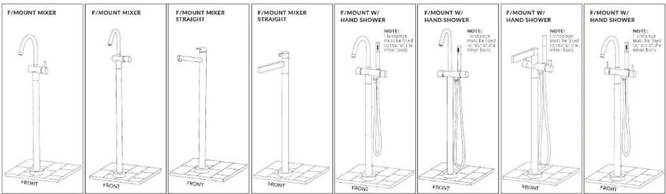
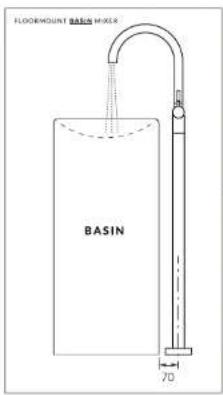
Floormount mixer Fixing distances
SUSSEX
Product code
VFMT
Floormount mixer 160mm
VFM200T
Floormount mixer 200mm
VFM250T
Floormount mixer 250mm
VFMHT
VFMMCT
Floormount mixer with hand held
Floormount mixer with curved outlet
VFMBMCT
Floormount basin mixer curved
text_image
FLODEMOUNT BASIN MIXER BASIN 70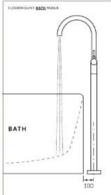
text_image
FLOORMOUNT BATH MIXER BATH 100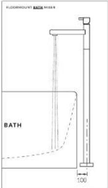
text_image
FLOORMOUNT BATH METER BATH 100
text_image
FLOORMOUNT BASIN MEXER BASIN 70
text_image
FLOORMOUNT BATH MIPER WITH HANDSHOWER BATH HAND PIECE TO REAR 100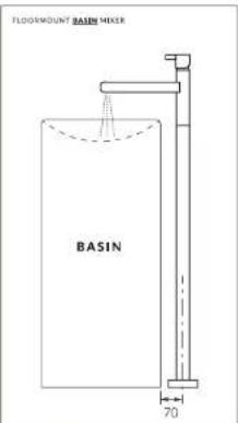
text_image
FLOORMOUNT BASIN MIXER BASIN 70
Voda
Floormount mixer Concrete floor Rough-in
SUSSEX
text_image
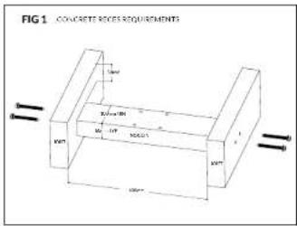
FIG 1 COLCRIDE SIDES REQUIREMENTS 50mm x 20mm x 30mm x 40mm x 50mm x 60mm x 70mm x 80mm x 90mm x 100mm x 110mm x 120mm x 130mm x 140mm x 150mm x 160mm x 170mm x 180mm x 190mm x 200mm x 210mm x 220mm x 230mm x 240mm x 250mm x 260mm x 270mm x 280mm x 290mm x 300mm x 310mm x 320mm x 330mm x 340mm x 350mm x 360mm x 370mm x 380mm x 390mm x 400mm x 410mm x 420mm x 430mm x 440mm x 450mm x 460mm x 470mm x 480mm x 490mm x 500mm x 510mm x 520mm x 530mm x 540mm x 550mm x 560mm x 570mm x 580mm x 590mm x 600mm x 610mm x 620mm x 630mm x 640mm x 650mm x 660mm x 670mm x 680mm x 690mm x 700mm x 710mm x 720mm x 730mm x 740mm x 750mm x 760mm x 770mm x 780mm x 790mm x 800mm x 810mm x 820mm x 830mm x 840mm x 850mm x 860mm x 870mm x 880mm x 890mm x 900mm x 910mm x 920mm x 930mm x 940mm x 950mm x 960mm x 970mm x 980mm x 990mm x 1000mm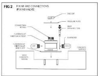
text_image
FIG 2 FIXING AND CONNECTIONS (FIXING VALVE) ON/OFF PRESSURE RATE FLOW DRYABLE TEST FLOOR/UP MOUNTING MOUNTING MOUNTING FLUORE CONCRETE SURFACE CONNECTION RITTING FLOOR/UP MOUNTING MOUNTING MOUNTING FLOOR/UP MOUNTING MOUNTING MOUNTING CONCRETE SURFACE CONNECTION RITTING FLOOR/UP MOUNTING MOUNTING MOUNTING CONCRETE SURFACE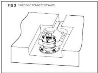
text_image
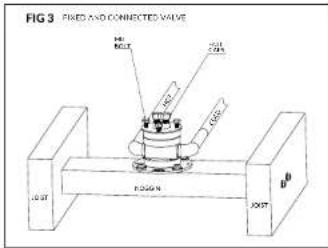
FIG 3 FREE AND CONNECTED VALVE
natural_image
Technical line drawing of a mechanical assembly with a central component and surrounding debris (no text or symbols)*To install this floormount fixing valve, a 50mm step down (recess) is required in the concrete slab. The floormount fixing valve is supplied with end caps, pressure plate and fixing bolts. Leave intact until fina fill off with the floormount mixer.
New concrete floor (pre-pour)
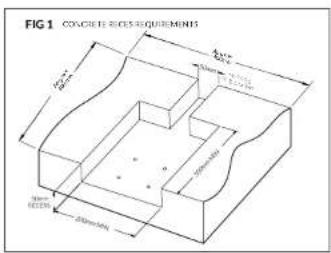
^a To install the Floormount Fixing Valve a 50mm step down (recess) is required in the concrete surface where the floormount is to be located.
- The recess area is to be a minimum of 200 x 300mm to allow enough room for the fixing valve to be fitted. NOTE: This can be a larger area if unsure of exact mounting position.
Important: the recess area is required to be 50mm deep and must be flat and level.
Existing concrete floor
- Cut 400 x 400mm section through concrete slab where the floormount mixer is to be located (Fig. 1).
- Remove cut section and drill for the appropriate concrete 'tie-rods' into side walls of cavity.
- Fit 'tie-rods' and pour concrete to create a 50mm stap down (recess) from the original concrete floor surface (Fig. 1).
NOTE: Recess area must be flat and level. - Hot and cold lines can be chased into the recessed area by cutting a minimum 50 x 50mm channel (Fig. 1).
Fixing and connections (Fig. 2 & 3)
- Connect 1/2" elbows (or male/female nipples) to Fixing Valve in preparation for the hot/cold water lines.
- Postion fixing valve into concreted recess area.
NOTE: Align "Front" to face bath or wash vessel. - Mark and drill for 8mm "dyna bolt" or other appropriate anchoring bolts (not supplied).
- Fix Floormount Fixing Valve and complete hot and cold water line connections.
- Ensure the valve is level and well anchored.
- Tighten "end caps" and perform water testing, and ensure there are no water leaks.
- Leave end caps, pressure plate and fixing bolts in the valve to protect the threads until final fit-off.
Back-filled recess (Fig. 4)
- Once all water connections are made and tested, fill in the recessed area and channelling up to the Fixing Valve with a mortar mix.
- After mortar has set, seal the area between mortar and the Fixing Valve.

Voda
Floormount mixer Wooden floor Rough-in
SUSSEX
text_image
FIG 1 CONCRETE RECES REQUIREMENTS 1mm M100mm M150mm M200mm M250mm M300mm M350mm M400mm M450mm M500mm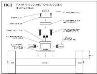
flowchart
graph TD
    A["FIXING AND CONNECTIONS WOODEN\n(FLOOR VALVE)"] --> B["FLIGHT LINE"]
    A --> C["FLOOR LINE"]
    B --> D["CONNECTED WITH\NOCO)"]
    C --> E["CONNECTED WITH\NOCO"]
    D --> F["FLIGHT LINE OF\NOCO"]
    E --> G["FLIGHT LINE OF\NOCO"]
    F --> H["FLIGHT LINE OF\NOCO"]
    G --> I["FLIGHT LINE OF\NOCO"]
    H --> J["FLIGHT LINE OF\NOCO"]
    I --> K["FLIGHT LINE OF\NOCO"]
    J --> L["FLIGHT LINE OF\NOCO"]
    K --> M["FLIGHT LINE OF\NOCO"]
    L --> N["FLIGHT LINE OF\NOCO"]
    M --> O["FLIGHT LINE OF\NOCO"]
    N --> P["FLIGHT LINE OF\NOCO"]
    O --> Q["FLIGHT LINE OF\NOCO"]
    P --> R["FLIGHT LINE OF\NOCO"]
text_image
FIG 3 FIXED AND CONNECTED VALVE 140 RCLT 251 725 160 F-500N 100 X05T X05T
text_image
FIG 4 BACKPILLED ACCESS F1. out. Q028 out.50 out.50 B BRough-in (Wooden floor)
- Fix a 100x50mm min noggin. 50mm below the top of the joists in the position where the floormount mixer is to be located (Fig. 1).
NOTE: the floormount mixer has been supplied to suit a concrete installation. Some parts need to be changed to suit a wooden floor. - To suit wooden flooring, remove the m8x25mm bolts and the pressure plate. Using a 6mm allen key, remove the two connection fittings (O-ring sealed) and replace with the longer version (tighten well).
- Add the Floormount Mixer Adapted Plate. Replace the Pressure Plate and loosely fit the M8x40mm bolts (Fig. 2)
NOTE: the shorter connection fittings and M8x25mm bolts will not be required. - Add appropriate elbows or 1/2" BSP nipples to allow for hot/cold water connections (not supplied).
- Secure Floormount Mixer Valve to coggin using appropriate wood screws (not supplied).
NOTE: "FRONT" to face water vessel. - Complete hot/cold water connections.
- Ensure the valve is level and well anchored.
Fixing and connections (Fig. 2 & 3)
- Connect 1/2" elbows (or male/female nipples) to Fixing Valve in preparation for the hot/cold water lines.
- Position fixing valve into concreted recess area.
NOTE: Align "Front" to face bath or wash vessel. - Mark and drill for 8mm "dyna bolt" or other appropriate anchoring bolts (not supplied).
- Fix Floormount Fixing Valve and complete hot and cold water line connections.
- Ensure the valve is level and well anchored.
- Tighten "end caps" and perform water testing, and ensure there are no water leaks.
- Leave end caps, pressure plate and fixing bolts in the valve to protect the threads until final fit-off.
Back-filled recess (Fig. 4)
- Once all water connections are made and tested, till in the recessed area and channelling up to the Fixing Valve with a mortar mix.
- After mortar has set, seal the area between mortar and the Fixing Valve.

Voda
Floormount mixer Concrete floor Fit-off
SUSSEX

text_image
FIG 5 FLOORMOUNT MIXER FLOORMOUNT COVERFLANGE N8 DOLT(K) FLOORMOUNT FITTING APPLY SEALANI LEVELING SCREWS TLE BLUE WATERPROOF 20mm 1 2 3 4 PRESSURE PLATE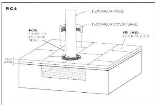
text_image
FIG 6 NOTE: FRONT TO MOUL WITH VEGET. 22mm AYRCK LOORMOUNT MIXER LOORMOUNT COVER LANGE FIN SHED FLOOR SURFACEFit-off (Concrete floor)
- Prior to installing, ensure floor around fixing valve is completely sealed.
- Raise the floormount cover flange.
- Remove "end caps" and retain if required.
- Connect hot and cold hoses from Floormount Mixer (a second person may be required to assist).
NOTE: the hose connection has a self sealing fitting. No sealant is required. - Tighten the hex nuts of the hose fittings using an appropriate spanner (tighten well).
- Carefully lower the mixer to meet the pressure plate.
NOTE: "Front" of Floormount Mixer must face the bath or wash vessel. - Align and fit supplied M8 bolts.
- Before fully tightening, allow water flow and check for water leaks.
- Tighten MB bolts and check Floormount Mixer is level. If levelling is required, loosen MB bolts and adjust levelling screws as required.
- To complete the installation, lower the cover flange until it meets the finished floor surface.
- Check mixer function and look for any leaks.

Voda
Floormount mixer Wooden floor Fit-off
SUSSEX

text_image
FIG 5 FLOORMOUNTIMKER FLOORMOUNT COVER FLANGE ME SOFT (34) FLOORMOUNTITTING TYPE LINES SCREW AFRIV STAIN ANT TILE GLUSE WATER FROCF WATER PERFECT BOARD NOGGIN B CUST JOIST JOIST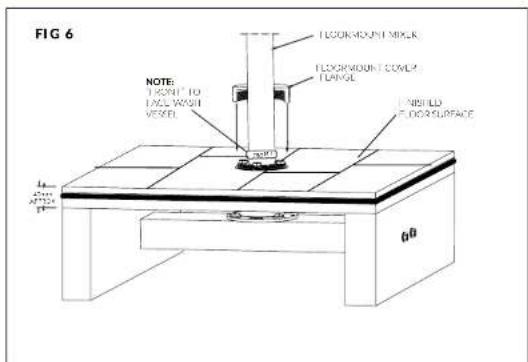
text_image
FIG 6 NOTE: TIGHT TO FALL WASH VESEL FLOORMOUNT MILEK FLOORMOUNT COVER CHANGE INSHLD FLOOR SURFACE L1 A2 A3 P1 00Fit-off (Wooden floor)
- Prior to installing, ensure floor around fixing valve is completely sealed.
- Raise the floormount cover flange.
- Remove "end caps" and retain if required.
- Connect hot and cold hoses from Floormount Mixer (a second person may be required to assist).
NOTE: the hose connection has a self sealing fitting. No sealant is required. - Tighten the hex nuts of the hose fittings using an appropriate spanner (tighten well).
- Carefully lower the mixer to meet the pressure plate.
NOTE: "Front" of Floormount Mixer must face the bath or wash vessel.
- Align and fit supplied M8 bolts.
- Before fully tightening, allow water flow and check for water leaks.
- Tighten M8 bolts and check Floormount Mixer is level. If levelling is required, loosen M8 bolts and adjust levelling screws as required.
- To complete the installation, lower the cover flange until it meets the finished floor surface.
- Check mixer function and look for any leaks.
Voda
Floormount mixer Installation kit Fit-off
SUSSEX